

Page 1

INSTRUCTIONS
SR-W5U
Hi-Vision VIDEO CASSETTE RECORDER
HD/SD
OPERATE HD SD S-VHS IN — R.A.E. —OUT
For Customer Use:
Enter below the Serial No. which is
located on the rear of the cabinet.
Retain this information for future
reference.
Model No. SR-W5U
Serial No.
LPT0002-0Q5A
Page 2

SAFETY PRECAUTIONS
CAUTION
RISK OF ELECTRIC SHOCK
DO NOT OPEN
CAUTION: TO REDUCE THE RISK OF ELECTRIC SHOCK.
REFER SERVICING TO QUALIFIED SERVICE PERSONNEL
DO NOT REMOVE COVER (OR BACK).
NO USER-SERVICEABLE PARTS INSIDE.
The lightning flash with arrowhead symbol,
within an equilateral triangle, is intended to
alert the user to the presence of uninsulated
“dangerous voltage” within the product’s
enclosure that may be of sufficient magnitude
to constitute a risk of electric shock to persons.
The exclamation point within an equilateral
triangle is intended to alert the user to the
presence of important operating and
maintenance (servicing) instructions in the
literature accompanying the appliance.
WARNING:
TO PREVENT FIRE OR SHOCK
HAZARD, DO NOT EXPOSE THIS
APPLIANCE TO RAIN OR
MOISTURE.
NOTE
This equipment has been tested and found to comply
with the limits for a Class A digital device, pursuant to
Part 15 of the FCC Rules. These limits are designed to
provide reasonable protection against harmful interference when the equipment is operated in a commercial
environment. This equipment generates, uses, and
can radiate radio frequncy energy, and if not installed
and used in accordance with the instruction manual,
may cause harmful interference to radio communications. Operation of this equipment in a residential area is likely to cause harmful interference in
which case the user will be required to correct the
interference at his own expense.
CAUTION
CHANGES OR MODIFICATIONS NOT APPROVED
BY JVC COULD VOID USER’S AUTHORITY TO OPERATE THE EQUIPMENT.
NOTE: The rating plate and the safety caution are on
the rear of the unit.
This video cassette recorder should be used with AC
120V
~
, 60 Hz only.
CAUTION:
To prevent electric shocks and fire hazards, do NOT
use any other power source.
When you are not using the video recorder for a long
period of time, it is recommended that you disconnect
the power cord from the AC outlet.
2
Page 3

TABLE OF CONTENTS
1 Precautions........................................................4
Features ..............................................................4
VCR.....................................................................5
Video Cassettes ..................................................5
Head Cleaning ....................................................6
Recording Modes and Types of the Cassettes... 6
Loading and Unloading the Cassette ................. 7
2 Controls and Connectors ................................ 8
Front Panel..........................................................8
Rear Panel ........................................................11
Remote Control .................................................12
3 Indicators and Displays ................................. 13
Display Panel ....................................................13
4 Preparations ....................................................14
Connections ......................................................14
5 Recording ........................................................16
Basic Operations...............................................16
How to Check the Tape Remaining Time......... 17
Retake Function ................................................17
6 Playback...........................................................18
Basic Procedure ................................................18
Special Playback Procedures........................... 19
Next Function ....................................................21
Index Search .....................................................21
Adjustment of the Playback Picture.................. 23
8 Editing ..............................................................27
Audio Dubbing...................................................27
Random Assemble Editing ............................... 28
Insert Editing .....................................................30
Preroll Editing....................................................31
Preroll Insert Editing..........................................32
9 Specifications..................................................33
7 Tape Dubbing ..................................................24
When Playing Back on SR-W5U and
Recording on Another Unit ............................... 24
When Playing Back on Another Unit and
Recording on SR-W5U......................................25
When Playing Back on a Video Movie and
Recording on SR-W5U......................................26
3
Page 4
1 PRECAUTIONS
Features
● W-VHS format HD mode offers high-definition
recording and playback of high-vision signals on a
base band.
● W-VHS format SD mode also available to ensure
high-quality picture for the existing TV format
sources.
● W-VHS metal compatible high-power Sendust
heads
● The existing VHS/S-VHS video can be recorded and
played back with a superb quality.
● Built-in RS-232C enables you to externally control
this unit from your personal computer.
With this video cassette recorder, you can enjoy the
HD and SD modes of W-VHS video. Be sure to use
cassette tapes marked with .
Since the VHS mode and S-VHS mode are also
available, use video cassettes marked with or
when you want to enjoy these modes.
What is HD mode? (HD denotes High
Definition)
In HD mode, HDTV signals are recorded using
multiple tracks, HDTV signal was originally
developed by NHK of Japan, and it stands for
High-Definition Television.HDTV is a next
generation broadcasting system which eables
high-definition picture quality in comparision to
conventional NTSC system.
What is SD mode? (SD denotes Standard
Definition)
In SD mode standerd TV signals are recorded
on a single track with high picture quality and
long recording times.
4
Page 5

1 PRECAUTIONS
VCR
● Avoid using the recorder in places subject to the
following conditions:
– extreme heat, cold, or humidity,
– dust,
– vibrations, and
– poor ventilation.
● Be careful of moisture condensation.
Do not use the recorder immediately after moving it
from a cold place to a warm place. The water vapor
in warm air will condense on the still-cold video
head drum and tape guides and may cause
damage to the tape and the recorder.
Video Cassettes
● Use video cassettes marked with / /
with this unit. C-cassettes can be used with a
C-cassette adapter (SA-CP11U) connected.
● Video cassettes marked with are
exclusively for use with a video cassette recorder
marked with . Loading such cassettes into
existing S-VHS or VHS cassette recorders may
cause a damage to the machine.
● Handle the recorder carefully.
• Do not block the ventilation openings.
• Do not place anything heavy on the recorder.
• Do not place anything which might spill on the top
cover of the recorder.
• Use in horizontal (flat) position only.
● During transportation,
• Avoid violent shocks to the recorder during
packing and transportation.
• Before packing, be sure to remove the cassette
from the recorder.
S-VHS, VHS cassettes
• To prevent accidental erasure, remove the
cassette’s safety tab.
• To record on a cassette whose safety tab has
been removed, cover the hole with adhesive tape.
● Any cassette is provided with a safety tab for
protecting it from accidental erasure. The cassette
with its safety tab set at a protective position
automatically starts playback when loaded into a
machine.
W-VHS cassettes
Slidable safety tab.
Protected
position
REC
Unprotected
position
REC
v Reverse side of a cassette is not usable.
v Before putting the cassette into storage, make sure
that the tape is uniformly wound up to its beginning.
5
Page 6
1 PRECAUTIONS
Head Cleaning
Perform head cleaning even 20 hours to enjoy
clear pictures.
Video heads get soiled with repeated recording and
playback, resulting in rough, uneven picture.
Perform cleaning of the tape transport mechanism
every 20 hours with the provided head cleaning tape
dedicated to W-VHS.
How to use the cleaning tape
1. Load the W-VHS dedicated head cleaning tape.
2. Press the PLAY button and then STOP button after
about 30 seconds.
3. Unload the head cleaning tape and execute a
usual recording and playback procedure on a WVHS cassette to see if audio/visual quality has
been recovered.
4. If tape quality does not pick up, repeat the
procedures 1. and 2. once or twice.
Cautions
● Do not rewind the cleaning tape after every use (for
about 30 seconds). You have only to start at the
position where the tape stopped in previous
cleaning. Rewind to the beginning when the tape
has been used to an end.
● 30 seconds are enough for one run of the cleaning
tape. To keep running the tape for longer than 45
seconds may damage the heads.
● If sound and picture quality does not recover with
the cleaning procedures repeated three times, there
may be some other causes of trouble. Consult your
JVC dealer.
● The W-VHS dedicated cleaning tape can be used
100 times.
● Recording or playback is not possible on the
cleaning tape.
● Do not use any cleaning tape other than the WVHS dedicated cleaning tape for this machine.
● The W-VHS dedicated cleaning tape can be used
only with the video cassette recorder marked with
.
Recording Modes and Types of the Cassettes
Recording modes available depend on the types of the cassette in use.
Cassettes in use Recording modes Recording speed
W-VHS HD SP
SD EP
S-VHS S-VHS SP/EP
Selectable
VHS VHS SP/EP
Selectable
Cautions
• HD recording at EP mode is not possible.
• SD recording at SP mode is not possible.
Remarks
S-VHS/VHS recording not possible.
HD/SD/VHS recording not possible.
HD/SD/S-VHS recording not possible.
6
Page 7
1 PRECAUTIONS
S
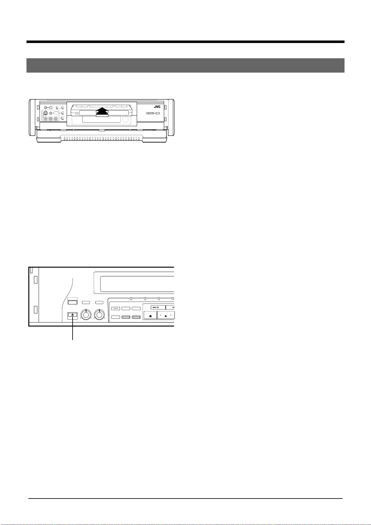
Loading and Unloading the Cassette
Loading
PHONES VOLUME
MIN MAX
REMOTE
PAUSE
VIDEO L– AUDIO –R
REC LEVEL
IR REMOTE
MANUAL
OFF
AUTO
ON
EDIT(HD REC)
NR(W-VHS PLAY)
ON
INPUT
OFF
LINE4
Y/C TIMING
R
O
L
TRACKING AUTO
1. Insert the cassette.
• Slowly push the center with its visible tape side
up.
• Counter display turns 0:00:00.
• The cassette with its safety tab removed
automatically starts playback.
Cautions
• Keep your hand or other foreign substances
away from the loading slot. Take special care of
young children to protect their hands from the
door.
• When the cassette automatically comes out,
insert it again after several seconds.
Unloading
1. Press the EJECT button.
OPERATE
EJECT
LR010
EJECT
HI-FI AUDIO
AUDIO OUT
SELECT
SELECT
BALANCE REC LEVEL
OPERATE HD SD S-VH
INDEX
629
MARK ERASE
TBC
COUNTER
COUNTER
RESET
ZERO
SEARCH
/REMAIN
REW FF
STOP PLAY
7
Page 8

2 CONTROLS AND CONNECTORS
Front Panel
21345678
PHONES VOLUME
VIDEO L– AUDIO –R
MIN MAX
REMOTE
PAUSE
MANUAL
AUTO
REC LEVEL
INPUT
LINE4
IR REMOTE
OFF
ON
EDIT(HD REC)
NR(W-VHS PLAY)
ON
OFF
Y/C TIMING
R
C
L
1[S-VIDEO/VIDEO/AUDIO INPUT 4] connectors
Connect to the S-VIDEO/VIDEO/AUDIO OUTPUT
connectors on the playback deck or camcorder
with the S-VIDEO/VIDEO/AUDIO cable when this
machine is used as a recording unit for editing.
If the sound is monaural, plug it to the AUDIO L
connector. Identical audio sound will be recorded
for left and right channels.
[REMOTE PAUSE] connector
When editing with a JVC camcorder, connect the
mini-plug cord to this connector.
2 [PHONES] connector
Accepts the mini plug type headphone.
[VOLUME] adjust knob
Adjust the sound level of headphone connected to
the PHONES connector.
3 [REC LEVEL] switch
MANUAL: Set to this position when adjusting the
Hi-Fi recording level and the volume balance
between left and right audio channels manually.
AUTO : Normally set to this position.
4 [IR REMOTE] switch
OFF:Set to this position when not operating with a
wireless remote control unit.
ON : Normally set to this position.
[EDIT(HD REC)/NR(W-VHS PLAY)] switch
When using W-VHS tapes, adjust the picture to
the desired tone.
ON : • Set to this position when noise is noticeable
during playback of HD/SD recorded tapes.
• Set to this position when recording from HiVision video cameras and from professional
equipment.
TRACKING AUTO
OFF:• Normally set to this position during play-
back.
• Set to this position when recording from
another W-VHS VCR.
[Y/C TIMING] switch
Adjusts the horizontal color phase.
R :Set to this position when the color phase shifts
toward the left.
C :Normally set to this position.
L :Set to this position when the color phase shifts
toward the right.
* This function is not effective while playing back a
tape recorded in the HD mode.
5 Tape loading slot door
6 Video unit display window
Displays the operational state of the recorder,
counter and so on.
7 Infrared beam receiving window
8 [TRACKING –/+] button
Suppresses the disturbances appearing on the
picture when a tape recorded on another machine
is played back (or put on slow motion playback).
[AUTO] button
Turns on and off the auto tracking facility.
8
Page 9

2 CONTROLS AND CONNECTORS
Front Panel
9
OPERATE
EJECT
%
0 # $!@
HI-FI AUDIO
AUDIO OUT
SELECT
SELECT
BALANCE REC LEVEL
LR010
^ )
OPERATE HD SD S-VHS IN — R.A.E. — OUT
INDEX
629
MARK ERASE
TBC
COUNTER
COUNTER
RESET
ZERO
SEARCH
/REMAIN
& * (
9 [OPERATE] button
Turns the power on and off.
0 [HI-FI AUDIO SELECT] button
Selects Hi-Fi audio sources to be played back.
Every press of this button changes right and left
audio [ left audio [ right audio one after the
other.
[AUDIO OUT SELECT] button
Selects audio to be played back.
Every press of this button changes Hi-Fi [ Normal,
one after the other.
! [629TBC] button
Corrects the distorted or blurred picture with an
S-VHS or VHS tape.
@ [INDEX MARK] button
Marks the index signal.
[INDEX ERASE] button
Erases the index signal.
# [OPERATE] lamp
Lights when the power is on.
[HD] lamp
Lights when HD mode is selected with a W-VHS
tape in use or when an HD-recorded tape is played
back.
[SD] lamp
Lights when SD mode is selected with a W-VHS
tape in use or when an SD-recorded tape is played
back.
REW FF
STOP PLAY
FWD
PAUSE/STIL
INDEX SEARCH
INSERT A.DUB
REC
q
REV
JOG
SHUTTLE
R.A.EDIT
HD INPUT
INPUT
SELECT
PREROLL EDIT
IN/OUT
START
PAUSE
START
SP/EP
w e r t
[IN-R.A.E-OUT] lamps
Lights when Random Assemble Editing mode is
selected and when IN/OUT points are set.
$ [HD INPUT] button
Input mode will change to HD input mode by
pressing this button when a cassette is not loaded
or when a W-VHS cassette is loaded in this unit.
% [EJECT] button
Ejects a cassette.
^ [BALANCE] adjust knob
Adjusts balance between right and left audio
channels.
[REC LEVEL] adjust knob
Adjusts Hi-Fi audio recording level. Carefully adjust
this knob, as a recording level that is too low may
lead to increased noise, and a level that is too high
may cause distortion.
& [COUNTER/REMAIN] button
Alternates the display window between the tape
counter display and the tape remaining time
display.
* [COUNTER RESET] button
Resets the tape counter display to 0:00:00.
( [ZERO SEARCH] button
Stops the tape at the position of 0:00:00 on the
display counter.
[S-VHS] lamp
Lights when an S-VHS cassette is loaded and
when an S-VHS-recorded tape is played back or
while recording in the S-VHS mode.
9
Page 10

2 CONTROLS AND CONNECTORS
Front Panel
) [REW] button
Rewinds the tape.
[FF] button
Fast forwards the tape.
[STOP] button
Stops any operation of the VCR.
[PLAY] button
Plays back the tape.
[PAUSE/STILL] button
Pauses the recording or changes the playback
picture to a still picture. Cancelled by pressing the
PLAY button.
q [INDEX SEARCH] buttons
Search for the start of the recorded section or the
section indicated by an INDEX signal, and then
starts normal playback.
[INSERT] button
Use when replacing part of pre-recorded tape with
other images and Hi-Fi sound.
[A.DUB] button
Use when replacing only the normal soundtrack
with other sound on a pre-recorded tape.
e [PREROLL EDITING OPERATION] buttons
Use for preroll editing.
r [Random Assemble Editing] buttons
Use for Random Assemble Editing.
t [JOG] dial
Use for frame-by-frame playback.
[SHUTTLE] ring
Use for variable-speed search.
[REC] button
Starts recording.
w [INPUT SELECT] button
Selects among video/audio signals HD, L1, S1, L2,
S3, L4 and S4.
•When W-VHS is in use, every press of the button
changes Hd-L1-S1-L2-S3-L4-S4.
•When S-VHS/VHS is in use, every press of the
button changes L1-S1-L2-S3-L4-S4.
[SP/EP] button
Selects between recording speeds.
10
Page 11
2 CONTROLS AND CONNECTORS
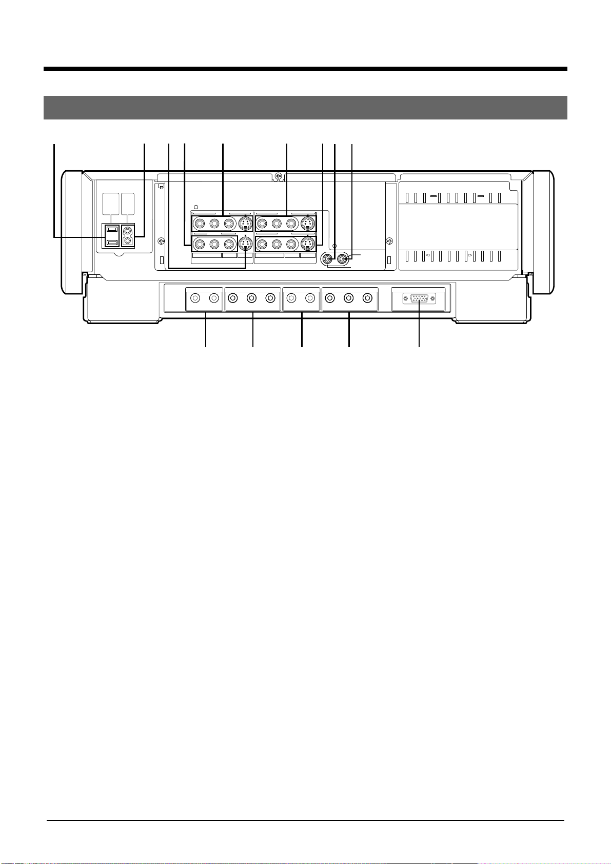
Rear Panel
12345
AC
AC
OUTPUT
INTPUT
MAX
120V
()
100W
60Hz
LINE 1 LINE 1
LINE 3
LINE 2
L
SR
VIDEO
INPUT
AUDIO IN
RL RLYP
HD/S3(W-VHS) HD(CAM/W-VHS) (HDTV/W-VHS) HD(HDTV/W-VHS) RGB(DISPLAY)
HD VIDEO IN HD VIDEO OUT1 HD VIDEO OUT2AUDIO OUT3
6789
LINE 2
VIDEO
RL
OUTPUT
B PR YPB PR
0!@# $
1 Socket for peripheral equipment
Connects up to a maximum of 100 W.
2 AC IN Socket
Make sure that the end of the provided power cord fits
into the power socket and plug it straight in until it stops.
3 S-VIDEO INPUT3 connector
When this machine is used as a recording unit for
editing, connect to the S-VIDEO OUTPUT connector on
the playback unit with the S-VIDEO cable.
4 VIDEO/AUDIO INPUT2 connectors
When this machine is used as a recording unit for editing,
connect to the VIDEO/AUDIO OUTPUT connectors on
the playback unit with the VIDEO/AUDIO cable.
5 S-VIDEO/VIDEO/AUDIO INPUT connectors
When this machine is used as a recording unit for editing,
connect to the S-VIDEO/VIDEO/AUDIO OUTPUT
connectors on the playback unit with the S -VIDEO/
VIDEO/AUDIO cable.
6 S-VIDEO/VIDEO/AUDIO OUTPUT 1 connectors
Connect to the S-VIDEO/VIDEO/AUDIO INPUT connectors on a TV or other unit with the S-VIDEO/VIDEO/
AUDIO cable.
7 S-VIDEO/VIDEO/AUDIO OUTPUT2 connectors
When this machine is used as a playback unit for editing,
connect to S-VIDEO/VIDEO/AUDIO INPUT connectors
with the S-VIDEO/VIDEO/AUDIO cable.
8 REMOTE connector
When externally controlling the machine using the
optional remote control unit (RM-G30U), connect the
remote control cable here.
REMOTE
R.A. EDIT
PREROLL
S
9 R.A.EDIT/PREROLL connector
Connect to the REMOTE PAUSE connector on the
recording unit with mini-plug cable for R.A.EDIT editing
or PREROLL editing.
0 HD/S3 AUDIO IN connectors
• Connect to the AUDIO OUTPUT connectors on a hivision video camera with the AUDIO cable.
• When HD VIDEO IN connectors on this unit are used
for editing, connect to the HD AUDIO OUT connectors
on the playback unit (W-VHS) with the AUDIO Cable.
• When S-VIDEO INPUT3 connectors on this unit are
used for editing, connect to the AUDIO OUT connectors on the playback unit with the AUDIO cable.
! HD VIDEO IN connectors
• Connect to the HD VIDEO OUT connectors on a hivision video camera with the HD VIDEO cable.
• When this machine is used as a recording unit for
editing, connect to the HD VIDEO OUT connectors on
the playback unit (W-VHS) with the HD VIDEO cable.
@ AUDIO OUT3 connectors
• Connect to the HD AUDIO IN connectors on a hi-vision
TV, etc., with the AUDIO cable.
• When this machine is used as a playback unit for
editing, connect to the HD AUDIO IN connectors on the
recording unit (W-VHS ) with the AUDIO cable.
# HD VIDEO OUT 1 connectors
• Connect to the HD VIDEO IN connectors on a hi-vision
TV, etc., with the HD cable.
• When this machine is used as a playback unit for
editing, connect to the HD VIDEO IN connectors on the
recording unit (W-VHS) with the HD cable.
$ HD VIDEO OUT 2 connector
Connect to the RGB input connector on PC monitors,
etc., with the RGB connector(15-pin).
11
Page 12

2 CONTROLS AND CONNECTORS
1
2
4
3
5
6
7
Remote Control
1 [TV CH–/+] buttons
Change channels on JVC TV.
TV
TV CH
OPERATE
8
VOLUME TV/VIDEO
9
VIDEO
TV/VIDEO
OPERATE
0
AUTO TRACKING
1¡
3
!
7¶8
@
REMOTE CONTROL UNIT
#
2 [VOLUME–/+] buttons
Adjust the volume of a JVC TV.
3 [TV/VIDEO] button
No function.
4 [AUTO] button
Turns on and off the auto tracking facility.
[TRACKING –/+] buttons
Suppress the disturbances appearing on the
picture when a tape recorded on another machine
is played back(or put on slow motion back).
5 [REW] button
Rewinds the tape.
6 [REC] button
Recording operation differs from that of the main
unit.
Recording starts when the play button is pressed
while pressing this button.
7 [PLAY] button
Plays back the tape.
8 [OPERATE] button
Turns on and off a JVC TV.
9 [TV/VIDEO] button
Selects the input mode of a JVC TV.
0 [OPERATE] button
Turns on and off this unit.
! [FF] button
Fast forwards the tape.
@ [PAUSE/STILL] button
Pauses the recording or changes playback picture
to a still picture.
Cancelled by pressing the PLAY button.
# [STOP] button
Stops any operation of the VCR.
12
Page 13

3 INDICATORS AND DISPLAYS
Display Panel
12345
AT
HM
1VCR Mode Display
Recording
Rewind/Fast forward Playback Still Picture/Slow Playback
Rewind Playback
2 Program Number Display
displays the program number of Random Assemble
Editing.
3 Auto Tracking Indicator
lights during auto tracking mode.
AT indicator is turned off by pressing AUTO button
for manual tracking adjustment.
4 ”Cassette loaded” Mark
appears when a cassette is loaded in VCR.
Recording
Pause
Insert Editing Audio Dubbing
Playback
Fast forward
Playback
Rew FF
Reverse Forward
Insert Editing +
Audio Dubbing
6
VISS
8
907
8 Recording Mode/Recording Speed display
displays the recording mode: HD(Hd)/SD(Sd)
when W-VHS tape is in use.
Displays the recording speed: SP/EP when S-VHS
or VHS tape is in use.
9 External Input
displays the selected input connectors.
Every press of the INPUT SELECT button changes
the display.
Hd can be selected only when a W-VHS tape is
being used or when there is no cassette loaded in
the unit.
Display Selected Connectors
Hd HD VIDEO IN & HD/S3 AUDIO IN connectors
(REAR)
L1 VIDEO & AUDIO INPUT 1 connectors(REAR)
S1 S-VIDEO &AUDIO INPUT1 connectors (REAR)
L2 VIDEO & AUDIO INPUT2 connectors (REAR)
S3 S-VIDEO INPUT3 & HD/S3 AUDIO IN
connectors (REAR)
L4 VIDEO & AUDIO INPUT4 connectors (FRONT)
S4 S-VIDEO & AUDIO INPUT4 connectors
(FRONT)
+8
4
0
6
10
–15dB
L R
5 VISS(VHS Index Search System) Indicator
flickers when recording starts and stays lit when
Index Search is performed.
6 Sound Level Indicator
indicates the level for both sound input and output.
7 Counter/Tape Remaining Time Display
displays the tape counter and the tape remaining
time from the current tape position to the tape end.
0 Sound volume display
displays the selected sound output mode.
Every press of the HI-FI AUDIO SELECT button
changes the display as follows.
LR L R
Every press of the AUDIO OUT SELECT button
changes the display as follows.
(Hi-Fi) (Normal)
LR
No display
13
Page 14

4 PREPARATIONS
Connections
The SR-W5U can be connected to the following units.
Connection to a high vision TV
Video signal connection
Audio signal connection
AC
OUTPUT
MAX
()
100W
Rear panel
AC
INTPUT
120V
60Hz
LINE 1 LINE 1
LINE 3
LINE 2
L
VIDEO
INPUT
AUDIO IN
RL RLYP
HD/S3(W-VHS) HD(CAM/W-VHS) (HDTV/W-VHS) HD(HDTV/W-VHS) RGB(DISPLAY)
LINE 2
S
RL
VIDEO
SR
OUTPUT
HD VIDEO IN HD VIDEO OUT1 HD VIDEO OUT2AUDIO OUT3
B PR YPB PR
REMOTE
R.A. EDIT
PRE ROLL
To HD audio
input connector
High vision TV
To HD video input connector
Connection to a monitor TV
Video signal connection
Audio signal connection
To audio input
connector
Monitor TV
To S-Video or Video input connector
Connection to a PC monitor equipped with
RGB connector (15-pin)
AUDIO OUT 3 (HD audio
output) connector
AC
AC
OUTPUT
INTPUT
MAX
120V
()
100W
60Hz
LINE 1 LINE 1
LINE 3
LINE 2
L
VIDEO
INPUT
AUDIO IN
HD VIDEO IN HD VIDEO OUT1 HD VIDEO OUT2AUDIO OUT3
RL RLYP
HD/S3(W-VHS) HD(CAM/W-VHS) (HDTV/W-VHS) HD(HDTV/W-VHS) RGB(DISPLAY)
AUDIO OUTPUT 1
connector
LINE 2
S
RL
VIDEO
SR
OUTPUT
B PR YPB PR
S-Video or VIDEO OUTPUT 1
connector
HD VIDEO OUT 1
connector
R.A. EDIT
PRE ROLL
REMOTE
Notes:
● With some PC monitors, the picture
may be stretched out or may shrink;
when this happens, adjust the picture
with the PC monitor's controls.
● During special playback, the picture
may be distorted or may disappear.
PC monitor
To RGB connector (15-pin)
14
AC
OUTPUT
MAX
()
100W
AC
INTPUT
120V
60Hz
LINE 1 LINE 1
LINE 3
LINE 2
L
VIDEO
INPUT
AUDIO IN
RL RLYP
HD/S3(W-VHS) HD(CAM/W-VHS) (HDTV/W-VHS) HD(HDTV/W-VHS) RGB(DISPLAY)
LINE 2
S
RL
VIDEO
SR
OUTPUT
HD VIDEO IN HD VIDEO OUT1 HD VIDEO OUT2AUDIO OUT3
B PR YPB PR
REMOTE
R.A. EDIT
PRE ROLL
HD VIDEO OUT 2
connector
Page 15

4 PREPARATIONS
Connections
Connection to a high vision camera.
AC
AC
OUTPUT
INTPUT
MAX
120V
()
100W
60Hz
LINE 1 LINE 1
LINE 3
LINE 2
LINE 2
To AUDIO
IN(HD/S3)
connector
To AUDIO
output
connector
OUTPUT
VIDEO
S
To
AUDIO
OUT 3
connector
VIDEO
L
INPUT
AUDIO IN
RL RLYP
HD/S3(W-VHS) HD(CAM/W-VHS) (HDTV/W-VHS) HD(HDTV/W-VHS) RGB(DISPLAY)
RL
SR
HD VIDEO IN HD VIDEO OUT1 HD VIDEO OUT2AUDIO OUT3
B PR YPB PR
To HD
VIDEO
IN
connector
To HD Video
output
connector
R.A. EDIT
PREROLL
REMOTE
To HD VIDEO
OUT 1
connector
To AUDIO
Input
connector
To HD Video
Input
connector
High vision camera
High vision TV
15
Page 16

5 RECORDING
Basic Operations
PHONES VOLUME
MIN MAX
REMOTE
PAUSE
VIDEO L– AUDIO –R
3
REC LEVEL
IR REMOTE
MANUAL
OFF
AUTO
ON
EDIT(HD REC)
NR(W-VHS PLAY)
ON
INPUT
OFF
LINE4
Y/C TIMING
R
O
L
HI-FI AUDIO
OPERATE
SELECT
BALANCE REC LEVEL
EJECT
LR010
2
AUDIO OUT
SELECT
OPERATE HD SD S-VHS IN — R.A.E. — OUT
INDEX
629
MARK ERASE
TBC
COUNTER
/REMAIN
COUNTER
RESET
ZERO
SEARCH
REW FF
STOP PLAY
PAUSE/STIL
INDEX SEARCH
INSERT A.DUB
REC
2
HD INPUT
INPUT
SELECT
PREROLL EDIT
START
SP/EP
PAUSE
R.A.EDIT
IN/OUT
START
JOG
SHUTTLE
TRACKING AUTO
REV
FWD
133 422
COUNTER/
REMAIN
Preparations
1 Turn the power on.
2 Select the recording mode.
Which mode is available depends on the type of the
cassette in use.
Cassette in use Recording mode
W-VHS HD mode
SD mode
S-VHS S-VHS mode
VHS VHS mode
HD mode
a. Load the W-VHS casssette.
b. Press the HD INPUT button. Then, HD lamp
lights and Hd is shown on the front window
display.
JOG DIAL/
SHUTTLE RING
SD mode
a. Load the W-VHS casssette.
b. Select L1, S1, L2, S3, L4 or S4 with INPUT
SELECT button. Then, SD lamp lights and Sd is
shown on the front window display.
S-VHS mode
a. Load the S-VHS cassette. The [S-VHS] lamp
lights.
b. Select L1, S1, L2, S3, L4 or S4 with INPUT
SELECT button.
c. Select recording speed with the SP/EP button.
Every pressing this button changes the SP [
EP [ SP.
VHS mode
a. Load the VHS cassette.
b. Select L1, S1, L2, S3, L4 or S4 with INPUT
SELECT button.
c. Select recording speed with SP/EP button.
16
Page 17

5 RECORDING
Basic Operations
3 Adjust the Hi-Fi recording level.
a. Set the REC LEVEL switch to "MANUAL".
b. Select Hi-Fi audio with the AUDIO OUT
SELECT button. (See page 18).
c. Adjust the recording level and L/R balance.
While checking with the audio level meter,
adjust with the REC LEVEL and BALANCE
knobs, set the level so that maximum volume
causes the meters to vary between 0dB to 4dB.
Perform adjustment carefully, as too low a
recording level may lead to a greater noise and
too high a level may cause a distortion.
How to Check the Tape Remaining Time
Press the COUNTER/REMAIN button during
recording or playback.
Every press of the button changes the display,
alternating between counter reading and tape
remaining time.
4 Start recording.
a. Press the REC button, whereupon recording
starts.
b. Press the PAUSE/STILL button for a brief pause
of recording.
c. Pressing the PLAY button resumes recording.
d. Press the STOP button to bring recording to an
end.
Notes:
● VHS recording is not possible with S-VHS
cassette.
● When pause remains for longer than five
minutes, the machine automatically stops
recording to protect tape and video head from
damage.
Notes:
● The tape remaining time is just an approximation you can refer to.
● Depending on the type of tape used, there may
be times when the tape remaining time reading
may not appear right away or is not correct.
Retake Function
You can cut unnecessary parts of a program during
recording. This facility does not work when a W-VHS
tape is used.
a. With the recording pause mode engaged, search
for the beginning of the unnecessary part (where
you want to adjoin the program) with JOG dial or
SHUTTLE ring.
b. Let go of the JOG/SHUTTLE at the start of the
unnecessary part.
The unit enters the pause mode when you do this.
c. Press PLAY button at the part of the program you
want to continue recording.
Recording resumes.
The part
to be
recorde
Pre-recorded section
Unnecessary
part
d
Cut the unnecessary part by moving the
recording start point.
Unnecessary
part
The
recording
start point
17
Page 18

6 PLAYBACK
Basic Procedure
4
HI-FI AUDIO
OPERATE
SELECT
BALANCE REC LEVEL
EJECT
LR010
AUDIO OUT
SELECT
OPERATE HD SD S-VHS IN — R.A.E. — OUT
INDEX
629
MARK ERASE
TBC
COUNTER
COUNTER
ZERO
/REMAIN
RESET
SEARCH
STOP PLAY
3
1 Load the tape.
The power is turned on. Playback automatically
starts with the tape protected (without safety tab).
2 Press the PLAY button.
Playback starts.
Press the PAUSE/STILL button to obtain a still
picture. Playback resumes by pressing the PLAY
button.
To monitor the HD-recorded tape, set the input
select switch on the high vision TV to HD input.
3 Press the STOP button to bring the playback to
an end.
Notes:
● With the still picture or slow play remaining for
longer than five minutes, the STOP mode is
automatically entered to protect the tape from
damage.
● In HD mode, the still picture may fail to come up
when quickly switching from PLAY to STILL.
1
SHUTTLE
R.A.EDIT
REW FF
PAUSE/STIL
INDEX SEARCH
INSERT A.DUB
REC
INPUT
SELECT
SP/EP
HD INPUT
PREROLL EDIT
START
PAUSE
IN/OUT
START
2
Audio Select
4 How to select HiFi audio channel?
a. Select with the HI-FI AUDIO SELECT button.
Every pressing the button changes HiFiL,R [
HiFiL [ HiFiR.
b. Check the audio output display on the front
panel display window.
L R : left and right audio
L : left audio
R : right audio
When selecting a reproduced audio (HiFi audio/
normal audio)
a. Select with the AUDIO OUT SELECT button.
Every pressing the button changes HiFi audio
[ normal audio. The tape for which HiFi audio
has not been recorded reproduces normal
audio.
b. Check the audio output display on the front
panel display window.
L R : HiFi audio
REV
JOG
FWD
18
No display : normal audio
Note:
Since normal audio is not recorded on a W-VHS
tape, selection between normal and mix audio is
not possible on a tape like that.
Page 19

6 PLAYBACK
Special Playback Procedures
HI-FI AUDIO
AUDIO OUT
OPERATE
SELECT
BALANCE REC LEVEL
EJECT
LR010
SELECT
629
TBC
COUNTER
/REMAIN
OPERATE HD SD S-VHS IN — R.A.E. — OUT
INDEX
MARK ERASE
COUNTER
RESET
ZERO
SEARCH
REW FF
STOP PLAY
PAUSE/STIL
1, 2
INDEX SEARCH
INSERT A.DUB
REC
INPUT
SELECT
SP/EP
HD INPUT
PREROLL EDIT
START
PAUSE
R.A.EDIT
IN/OUT
START
JOG
SHUTTLE
FWD
REV
Variable Speed Playback
1 Press FF or REW button to fast forward or rewind
during playback.
How to press the FF
and REW buttons
Press and let your hand off
(latch) immediately
Keep pressing
S-VHS /VHS tape W-VHS tape
SP EP HD SD
about 7 X about 21 X about 7 X about 20 X
speed speed speed speed
about 7 X about 15 X about 7 X about 14 X
speed speed speed speed
REC mode
Monitoring the Video during FF or REW
2 Video can be monitored by pressing the FF button
during fast forward or the REW button during
rewinding and immediately letting your hand off the
buttons. (open search)
How to cancel the variable speed playback
Pressing the PLAY button resumes normal playback.
Letting your finger off resumes normal playback.
TV screen
Input picture
FF or REW going on
f
Searched picture
Press the FF/REW button and
let it off immediately.
Open search going on
19
Page 20

6 PLAYBACK
Special Playback Procedures
HI-FI AUDIO
OPERATE
SELECT
BALANCE REC LEVEL
EJECT
LR010
AUDIO OUT
SELECT
OPERATE HD SD S-VHS IN — R.A.E. — OUT
INDEX
629
MARK ERASE
TBC
COUNTER
COUNTER
ZERO
/REMAIN
RESET
SEARCH
STOP PLAY
Variable Speed Search
Turn the SHUTTLE ring during playback or still picture
playback.
Still picture playback is engaged immediately after
letting your hand go.
Playback speed when a W-VHS tape is in use.
Still
Rewind
Reverse
search
-11
Reverse
slow
Reverse
play
-1/6
-1
-3
-5
-7
-30
-14
-1
-2
-6
Slow
motion
Play
-1/11
1/18
1/6
1
1/18
-1/18
-1/6
1/6
3
1
4
6
14
5
30
SD mode
Forward
Forward
search
7
11
HD mode
Playback speed when a S-VHS/VHS tape is in use.
Still
REW FF
FWD
PAUSE/STIL
INDEX SEARCH
INSERT A.DUB
REC
INPUT
SELECT
SP/EP
HD INPUT
PREROLL EDIT
START
PAUSE
R.A.EDIT
IN/OUT
START
JOG
SHUTTLE
REV
JOG DIAL/
SHUTTLE RING
Notes:
● The playback picture will be distorted when the
playback speed changes during special playback
in SD or HD mode.
● There may be times when noise bars appear at
the top/bottom of the screen during high-speed
search in SD or HD mode.
● The playback picture will be distorted during
frame-by frame and slow-motion playback in HD
mode. Or if the playback picture does not move
during slow-motion playback, adjust the
TRACKING – or + button so that it moves.
● Only during the reverse slow-motion playback in
HD mode, the playback picture moves by 2
frames each.
● It may take a few minutes to return to the normal
playback when pressing the PLAY button from
the SD or HD still picture playback mode.
● Audio sound cannot be heard during variable
speed search or frame-by-frame playback.
● After 5 minutes in the still picture or slow-motion
playback mode, the STOP mode is automatically
entered to protect the tape from damage.
20
Rewind
Reverse
search
-11
Reverse
slow
Reverse
play
-1/6
-1
-3
-5
-7
-31
-15
-1
-3
-7
Slow
motion
Play
-1/18
1/18
1/6
1
1/18
-1/18
-1/6
1/6
2
1
2
7
15
5
31
EP mode
Forward
Forward
search
7
11
SP mode
Frame-by-frame playback with JOG dial
Turn the JOG dial during playback and or still picture
playback.
When you stop turning the JOG dial, still picture
playback starts.
Page 21

6 PLAYBACK
Next Function/Index Search
OPERATE REW INDEX SEARCH
OPERATE
EJECT
LR010
EJECT
HI-FI AUDIO
AUDIO OUT
SELECT
SELECT
BALANCE REC LEVEL
OPERATE HD SD S-VHS IN — R.A.E. — OUT
INDEX
629
MARK ERASE
TBC
COUNTER
COUNTER
ZERO
/REMAIN
RESET
SEARCH
STOP PLAY
STOP
ZERO SEARCH
COUNTER RESET
Next Function
After the tape is fully rewound, functions such as playing
back, unloading the cassette and turning the power off, can
be automatically executed.
• To play back
Press the PLAY button within 2 seconds after pressing
REW button.
flickers on the front panel display window.
Playback automatically starts at the beginning of the tape.
• To unload the cassette
Press the EJECT button within 2 seconds after pressing
REW button.
] flickers on the front panel display window.
The cassette is automatically ejected at the beginning of
the tape.
• To turn the power off
Press the OPERATE button within 2 seconds after
pressing REW button.
OPERATE lamp flickers.
The power is automatically turned off at the beginning of
the tape.
To engage the next function at the counter reading of
0:00:00, press the ZERO SEARCH button instead of
REW.
FWD
REW FF
PAUSE/STIL
INDEX SEARCH
INSERT A.DUB
REC
INPUT
SELECT
SP/EP
HD INPUT
PREROLL EDIT
START
PAUSE
R.A.EDIT
IN/OUT
START
JOG
SHUTTLE
REV
PLAY
Index Search playback
This facility searches for the index signal recorded on the
tape where playback starts.
1. Press the INDEX SEARCH button during stop or
playback to specify a desired address.
The desired address is automatically searched, whereupon the tape is automatically played back.
Every press of the forward button increases the number
and every press of the reverse button decreases the
number. Address up to ±9 can be specified.
2. Press the STOP button to cancel this search.
Video unit display window.
VISS
Zero Search
The tape rewinds or fast-forwards to the counter reading of
0:00:00, then stops.
Press the ZERO SEARCH button during stop or playback.
Press the COUNTER RESET button to return to the counter
reading of 0:00:00.
REPEAT playback
Repeat playback from the beginning of the tape to the end
of the tape.
1. Press the PLAY button for longer than 5 seconds.
flickers on the front panel display and stops at the
beginning of the tape after repeating playback for 20
times.
2. Press the STOP button to cancel this function at any
time.
21
Page 22

6 PLAYBACK
Index Search
HI-FI AUDIO
OPERATE
SELECT
BALANCE REC LEVEL
EJECT
LR010
AUDIO OUT
SELECT
OPERATE HD SD S-VHS IN — R.A.E. — OUT
INDEX
629
MARK ERASE
TBC
COUNTER
COUNTER
RESET
ZERO
SEARCH
/REMAIN
INDEX MARK/ERASE
Recording the Index Signal
Index signal can be recorded on an arbitrary section
of the tape.
Index signal is automatically recorded at in the
beginning of recording.
During recording or playback
Press the INDEX MARK button.
VISS flickers on the front panel display window,
whereupon the index signal is recorded.
The VISS goes off, finishing the recording
procedure.
REW FF
STOP PLAY
PLAY
FWD
PAUSE/STIL
INDEX SEARCH
INSERT A.DUB
REC
INPUT
SELECT
SP/EP
HD INPUT
PREROLL EDIT
START
PAUSE
R.A.EDIT
IN/OUT
START
JOG
SHUTTLE
REV
Erasing the Index Signal
The index signal recorded on the tape can be erased.
a. Enter playback or still picture playback several
seconds before the index signal to be erased.
b. Press the INDEX ERASE button.
VISS is shown on the front panel display window.
The tape automatically runs to erase the index
signal.
c. The VISS display disappears, finishing the erasure
of the index signal.
Tape goes on playing back.
During Recording Pause or Still Picture Playback
a. Press the INDEX MARK button.
VISS is shown on the front panel display window.
b. Press the PLAY button.
VISS flickers, whereupon the index signal is
recorded.
c. VISS disappears, finishing the recording
procedure.
22
Notes:
● When recording an index signal on a recorded
tape, perform it in the playback mode. In record
mode, previous video or audio will be erased.
● Record an index signal at a due distance from a
neighboring index signal to avoid operational
error.
● With VISS shown on display, do not operate
other buttons.
● If the record speed is changed from SP to EP
near the index signal, the picture may be
disturbed after recording or erasing the index
signal is finished.
● Recording or erasure cannot take place on a
protected tape (without safety tab) or an
unrecorded tape.
Page 23

6 PLAYBACK
Adjustment of Playback Picture
TRACKING –/+Y/C TIMING
AUTO
PHONES VOLUME
VIDEO L– AUDIO –R
MIN MAX
REMOTE
PAUSE
REC LEVEL
IR REMOTE
MANUAL
OFF
AUTO
ON
EDIT(HD REC)
NR(W-VHS PLAY)
ON
INPUT
OFF
LINE4
Y/C TIMING
R
C
L
HI-FI AUDIO
OPERATE
SELECT
BALANCE REC LEVEL
EJECT
LR010
AUDIO OUT
SELECT
OPERATE HD SD S-VHS IN — R.A.E. — OUT
INDEX
629
MARK ERASE
TBC
COUNTER
COUNTER
ZERO
SEARCH
STOP PLAY
/REMAIN
RESET
629 TBC
To correct distortion of the picture
Press the 629TBC button to display " (TBC ON)" on
the front panel display window.
● Every press of the button changes the display,
(OFF) alternately.
● Depending on the type of signal recorded on the tape, the
playback picture may not be clearly visible. In that case,
the picture may be better by setting to "OFF".
● When playing back a W-VHS tape, TBC for W-VHS works
regardless of the "ON" or "OFF" setting.
This facility is helpful for the following occasions.
• Tape recorded with a camcorder.
• Tape used repeatedly.
• When using this unit as a playback machine during
dubbing.
(ON) [
TRACKING AUTO
FWD
REV
JOG
SHUTTLE
R.A.EDIT
REW FF
PAUSE/STIL
INDEX SEARCH
INSERT A.DUB
REC
INPUT
SELECT
SP/EP
HD INPUT
PREROLL EDIT
START
PAUSE
IN/OUT
START
PAUSE/STILL
When there is too much noise in the playback
picture
When auto tracking of this unit is not effective, adjust the
tracking manually.
1. Press the AUTO button during playback.
• AT display on the display panel of this unit disappears
and auto tracking is disengaged.
• Pressing it again returns to the auto tracking mode.
2. Adjust with the TRACKING–/+ button.
When noise appears during still picture/slowmotion playback
1. Press PAUSE/STILL button for longer than 2 seconds to
perform slow-motion playback.
2. Adjust with the TRACKING–/+ button.
• Tracking adjustment may not be entirely effective when
playing back a tape with a poor quality recording.
To adjust the picture when the color phase shifts
from side to side during playback
When the color phase shifts toward the left, set the Y/C
TIMING switch to "R".
When the color phase shifts toward the right, set the Y/C
TIMING switch to "L".
Normally set to "C".
The Y/C TIMING switch has no effect when 629TBC is set
to "OFF".
23
Page 24

7 TAPE DUBBING
When Playing Back on SR-W5U and Recording on Another Unit
AC
OUTPUT
MAX
()
100W
Audio output
To video input connector
AC
INTPUT
120V
60Hz
LINE 1 LINE 1
LINE 3
LINE 2
AUDIO IN
RL RLYP
HD/S3(W-VHS) HD(CAM/W-VHS) (HDTV/W-VHS) HD(HDTV/W-VHS) RGB(DISPLAY)
LINE 2
RL
SR
L
VIDEO
OUTPUT
INPUT
HD VIDEO IN HD VIDEO OUT1 HD VIDEO OUT2AUDIO OUT3
B PR YPB PR
VIDEO
R.A. EDIT
S
PRE ROLL
REMOTE
S Video (Video) output
To audio input
connector
(To HD video/audio input)
PHONES VOLUME
VIDEO L– AUDIO –R
MIN MAX
REMOTE
PAUSE
MANUAL
AUTO
REC LEVEL
INPUT
LINE4
IR REMOTE
OFF
ON
EDIT(HD REC)
NR(W-VHS PLAY)
ON
OFF
Y/C TIMING
R
C
L
TRACKING AUTO
NR
Another unit (as a recording machine)
1 Set the recording machine to external input.
2 Put the recording to a pause.
SR-W5U (as a playback machine)
3 Start playback shortly before the section where you
want to PLAY.
•When noise appears during playback with W-VHS
tape, set the NR switch to "ON".
Another unit (as a recording machine)
4 Start recording at a section of the program you
want to dub.
5 To finish, press the STOP button. Extra recording
can be avoided by stopping the recording machine
then the SR-W5U.
SR-W5U (as a playback machine)
6 Press the STOP button.
7 If the NR switch was set to "ON" in step 3, set it
back to "OFF".
● When dubbing a high vision video, use the HD
video cable, provided that the recording VCR is
equipped with the HD video input and HD audio
input connectors.
24
Page 25

7 TAPE DUBBING
When Playing Back on Another Unit and Recording on SR-W5U
To S Video (Video) input
S Video (Video)
output
Audio output
(HD video/audio output)
To audio input connector
AC
AC
OUTPUT
INTPUT
MAX
120V
()
100W
60Hz
(To HD video/audio input)
LINE 1 LINE 1
LINE 3
LINE 2
AUDIO IN
RL RLYP
HD/S3(W-VHS) HD(CAM/W-VHS) (HDTV/W-VHS) HD(HDTV/W-VHS) RGB(DISPLAY)
LINE 2
RL
SR
L
VIDEO
OUTPUT
INPUT
HD VIDEO IN HD VIDEO OUT1 HD VIDEO OUT2AUDIO OUT3
B PR YPB PR
VIDEO
R.A. EDIT
S
PRE ROLL
REMOTE
PHONES VOLUME
VIDEO L– AUDIO –R
MIN MAX
REMOTE
PAUSE
MANUAL
AUTO
REC LEVEL
INPUT
LINE4
IR REMOTE
OFF
ON
EDIT(HD REC)
NR(W-VHS PLAY)
ON
OFF
Y/C TIMING
R
C
L
OPERATE HD SD S-VHS IN — R.A.E. — OUT
INDEX
MARK ERASE
ERINCOUNTER
RESET
SEARCH
EDIT
SR-W5U (as a recording machine)
1 Select the input in connection by pressing the
INPUT SELECT button.
•You can change the input quickly by pressing HD
INPUT button.
•Set the EDIT switch to "ON" when connecting to
high vision camera and recording in HD mode.
2 Press the REC button while pressing the PAUSE
button to bring recording to a pause.
Another unit (as a playback machine)
3 Start playback shortly before the section where you
want to dub.
SR-W5U (as a recording machine)
4 Press the PLAY button at a section where you want
to dub.
5 To bring recording to a pause, press the PAUSE
button.
6 To finish, press the STOP button.
• Extra recording can be avoided by stopping the
SR-W5U then the playback machine.
ZERO
FWD
REV
JOG
SHUTTLE
R.A.EDIT
REW FF
STOP PLAY
PAUSE/STIL
INDEX SEARCH
INSERT A.DUB
REC
INPUT
SELECT
SP/EP
HD INPUT
PREROLL EDIT
START
PAUSE
IN/OUT
START
HD INPUT
INPUT SELECT
Another unit (as a playback machine)
7 Press the STOP button.
SR-W5U (as a recording machine)
8 If EDIT switch was set to "ON" in step 1, set it back
to "OFF".
● When dubbing a high vision video, use the HD
video cable, provided that the recording VCR is
equipped with the HD video output and HD audio
output connectors.
● When dubbing from an audio unit, record the
video together with the audio.
● When record pause stays for longer than five
minutes, the machine automatically stops to
protect the tape and video heads from damage.
● What you have recorded on the video cassette
recorder cannot be used without approval of the
copyright holder, except that it is solely for
personal amusement.
25
Page 26

7 TAPE DUBBING
When Playing Back on a Video Movie and Recording on SR-W5U
EDIT connector
S Video output
PHONES VOLUME
MIN MAX
REMOTE
PAUSE
VIDEO L– AUDIO –R
connector
AV output
connectors
HI-FI AUDIO
OPERATE
SELECT
BALANCE REC LEVEL
EJECT
LR010
AUDIO OUT
SELECT
OPERATE HD SD S-VHS IN — R.A.E. — OUT
INDEX
629
MARK ERASE
TBC
COUNTER
COUNTER
RESET
ZERO
SEARCH
/REMAIN
● When dubbing, REC start/stop on this machine
can be controlled from the video movie. (Master
edit control function)
● This can be operated when connected with a
JVC’s video movie.
● Please read the instruction manual of the video
movie.
● Refer to page 15, 25 to connect to high vision
camera and to record in HD mode.
REC LEVEL
IR REMOTE
MANUAL
OFF
AUTO
ON
EDIT(HD REC)
NR(W-VHS PLAY)
ON
INPUT
OFF
LINE4
Y/C TIMING
R
C
L
REW FF
STOP PLAY
TRACKING AUTO
FWD
PAUSE/STIL
INDEX SEARCH
INSERT A.DUB
REC
INPUT
SELECT
SP/EP
HD INPUT
PREROLL EDIT
START
PAUSE
R.A.EDIT
IN/OUT
START
JOG
SHUTTLE
REV
INPUT SELECT
SR-W5U (as a recording machine)
7 Recording is brought to a pause.
Video movie (as a playback machine)
8 When resuming recording, press the EDIT button.
SR-W5U (as a recording machine)
9 Recording is re-started.
SR-W5U (as a recording machine)
1 Select S4 or L4 with the INPUT SELECT button.
2 Press the REC button while pressing the PAUSE
button to bring recording to a pause.
Video movie (as a playback machine)
3 Put the video movie to a still playback mode at a
section you want to dub.
4 Press the EDIT button.
SR-W5U (as a recording machine)
5 The machine starts recording.
Video movie (as a playback machine)
6 Press the PAUSE button at a section where you
want to stop.
26
Video movie (as a playback machine)
10 When finishing, press the STOP button.
SR-W5U (as a recording machine)
11 The machine is brought to a pause.
12 Finish with the STOP button.
● When SD-recording with the SR-W5U by playing
back a tape having edit points, pictures may be
distorted at these edit points.
● When record pause stays for longer than five
minutes, the machine automatically stops to
protect the tape and video heads from damage.
Page 27

8 EDITING
Audio Dubbing
When a W-VHS tape is used, audio dubbing is not possible since it has no normal audio soundtrack.
The unit (as a playback machine):
CD Player
To audio output connector
To audio input connector
AC
AC
OUTPUT
INTPUT
MAX
120V
()
100W
60Hz
LINE 1 LINE 1
LINE 3
LINE 2
SR
RL
L
INPUT
VIDEO
LINE 2
OUTPUT
VIDEO
S
REMOTE
R.A. EDIT
PREROLL
AUDIO IN
RL RLYPBP
HD/S3(W-VHS) HD(CAM/W-VHS) (HDTV/W-VHS) HD(HDTV/W-VHS) RGB(DISPLAY)
HD VIDEO IN HD VIDEO OUT1 HD VIDEO OUT2AUDIO OUT3
The unit (as a recording machine)
The unit (as a recording machine)
1 Select the connected input with the INPUT SELECT
button.
2 Play back the tape and search for the beginning of
the section where you want to dub with JOG dial or
SHUTTLE ring and engage the still playback mode.
3 Press the A.DUB button
• is displayed on the front panel display window
and the unit enters the audio dubbing pause
mode.
The unit (as a playback machine)
4 Start playback shortly before the section you want
to dub.
The unit (as a recording machine)
5 Press the PLAY button at the section where you
want to dub.
•Audio dubbing starts.
6 Press the STOP button to finish.
R
YPBP
R
● Set the counter reading to 0:00:00 by pressing
COUNTER RESET button at the edit-out point
before step 2 in order to determine the edit-out
point and to dub.
Audio dubbing stops automatically when the
counter reading reaches 0:00:00 and enters
playback.
● When monitoring the sound during or after audio
dubbing, select the desired soundtrack with the
AUDIO OUT SELECT button.
● After audio dubbing, normal audio soundtrack is
selected. Return to the Hi-Fi soundtrack with the
AUDIO OUT SELECT button.
The unit (as a playback machine)
7 Press the STOP button.
27
Page 28

8 EDITING
Random Assemble Editing
(Ex.) Random Assemble Editing in the HD mode using 2 units of SR-W5U.
It is convenient to cut unnecessary parts, change the scene orders or to dub these to another video recorder. You
can select as many as 8 segments.
The unit as a playback machine
AC
AC
OUTPUT
INTPUT
MAX
120V
()
100W
60Hz
To AUDIO OUT 3
connector
To AUDIO IN
(HD/S3)
connector
AC
AC
OUTPUT
INTPUT
MAX
120V
()
100W
60Hz
LINE 1 LINE 1
LINE 3
LINE 2
L
AUDIO IN
RL RLYP
HD/S3(W-VHS) HD(CAM/W-VHS) (HDTV/W-VHS) HD(HDTV/W-VHS) RGB(DISPLAY)
SR
VIDEO
INPUT
HD VIDEO IN HD VIDEO OUT1 HD VIDEO OUT2AUDIO OUT3
RL
BPR
OUTPUT
LINE 2
VIDEO
S
R.A. EDIT
PREROLL
REMOTE
YPBP
R
To HD
VIDEO
OUT 1
connector
To HD
VIDEO IN
connector
LINE 1 LINE 1
LINE 3
LINE 2
L
AUDIO IN
RL RLYP
HD/S3(W-VHS) HD(CAM/W-VHS) (HDTV/W-VHS) HD(HDTV/W-VHS) RGB(DISPLAY)
VIDEO
SR
INPUT
HD VIDEO IN HD VIDEO OUT1 HD VIDEO OUT2AUDIO OUT3
RL
BPR
OUTPUT
LINE 2
VIDEO
S
R.A. EDIT
PREROLL
REMOTE
YPBP
R
To R.A.EDIT/
PREROLL
connector
To REMOTE
PAUSE
connector on
the front
panel
R.A.E. IN/OUT LAMP
HI-FI AUDIO
OPERATE
SELECT
BALANCE REC LEVEL
EJECT
LR010
OPERATE HD SD S-VHS IN — R.A.E. — OUT
AUDIO OUT
SELECT
INDEX
629
MARK ERASE
TBC
COUNTER
COUNTER
/REMAIN
RESET
ZERO
SEARCH
COUNTER RESET
COUNTER/REMAIN
STOP PLAY
REW FF
PAUSE/STIL
INDEX SEARCH
INSERT A.DUB
REC
HD INPUT
R.A. EDIT
R.A.EDIT
HD INPUT
INPUT
SELECT
PREROLL EDIT
IN/OUT
START
START
SP/EP
PAUSE
START
JOG
SHUTTLE
FWD
REV
IN/OUT
The unit as a recording machine
The unit (as a playback machine)
1 Press the R.A.EDIT button.
R.A.E. IN lamp will light.
Video unit display window
The current counter value
HM
Program number
Recording mode
2 Start playback and press the IN/OUT button at the
edit-in point (the beginning of the segment).
R.A.E. OUT lamp will light.
HM
In-point
3 Press the IN/OUT button at the edit-out point (the
end of the segment).
•R.A.E. IN lamp will light.
•Repeat steps 2-3, as many as 8 segments can be
selected.
HM
Out-point
4 Press PAUSE button to enter still picture playback
after setting IN/OUT points.
The unit (as a recording machine)
5 Press the HD INPUT button to set to external
input(Hd).
6 Enter the recording pause mode.
28
Page 29

8 EDITING
Random Assemble Editing
The unit (as a playback machine)
7 Press the START button.
•Editing begins in programmed order, dubbing
continues automatically until the last edit-out point.
•This function shuttle searches from edit-out point to
the next edit-in point.
•When editing is completed;
The unit (as a playback machine) : will be in
stop mode
The unit (as a recording machine) : will be in
recording pause mode
The unit (as a recording machine)
8 Press the STOP button.
The unit (as a playback machine)
9 Press the R.A.EDIT button.
•R.A. EDIT ends.
To cancel or change in-or-out points
1. After completing step 3, press COUNTER
RESET button.
• The last-registered counter number will
disappear.
Every press of the COUNTER RESET button
erases the last registered number.
• Cancelling and changing the counter value
while programming is not possible.
2. Re-do steps from 2 – 3 to change.
● Press the COUNTER/REMAIN button to display
the total recording time of each program on the
front panel display window.
Every press of the button changes the display
as follows:
counter–the tape remaining time –the total
recording time of all the segments
● Out-point counter value can be registered only
when it is higher than in-point counter value.
● Actual in- or out-point may differ slightly from
your scene selection.
● Segments with no registered out-point cannot
be executed.
● The total time on the counter display and the
added up recording time of each program are
sometimes not the same since counter display
for in-or out-points doesn't show a numerical
value of less than 1 second.
● If it takes more than 5 minutes to search for an
in-point, the unit's (as a recording machine)
Record Pause mode is cancelled and editing
doesn't take place.
● At the beginning /end of the tape in the unit (as
a playback machine), Random Assemble
Editing is sometimes not available.
29
Page 30

8 EDITING
Insert Editing
(Ex.) Insert Editing using 2 units of SR-W5U in the HD mode.
The unit as a playback machine
AC
AC
OUTPUT
INTPUT
MAX
120V
()
100W
60Hz
To AUDIO OUT 3
connector
To AUDIO IN
(HD/S3)
connector
AC
AC
OUTPUT
INTPUT
MAX
120V
()
100W
60Hz
LINE 1 LINE 1
LINE 3
LINE 2
L
INPUT
AUDIO IN
RL RLYP
HD/S3(W-VHS) HD(CAM/W-VHS) (HDTV/W-VHS) HD(HDTV/W-VHS) RGB(DISPLAY)
RL
SR
VIDEO
HD VIDEO IN HD VIDEO OUT1 HD VIDEO OUT2AUDIO OUT3
BPR
OUTPUT
LINE 2
VIDEO
S
R.A. EDIT
PRE ROLL
REMOTE
YPBP
R
To HD
VIDEO
OUT 1
connector
To HD
VIDEO IN
connector
LINE 1 LINE 1
LINE 3
LINE 2
L
INPUT
AUDIO IN
RL RLYP
HD/S3(W-VHS) HD(CAM/W-VHS) (HDTV/W-VHS) HD(HDTV/W-VHS) RGB(DISPLAY)
RL
SR
VIDEO
HD VIDEO IN HD VIDEO OUT1 HD VIDEO OUT2AUDIO OUT3
BPR
OUTPUT
LINE 2
VIDEO
S
R.A. EDIT
PRE ROLL
REMOTE
YPBP
R
HI-FI AUDIO
OPERATE
SELECT
BALANCE REC LEVEL
EJECT
LR010
OPERATE HD SD S-VHS IN — R.A.E. — OUT
AUDIO OUT
SELECT
INDEX
629
MARK ERASE
TBC
COUNTER
COUNTER
/REMAIN
RESET
ZERO
SEARCH
COUNTER RESET
STOP PLAY
REW FF
INDEX SEARCH
INSERT A.DUB
PAUSE/STIL
REC
INSERT
HD INPUT
JOG
SHUTTLE
R.A.EDIT
HD INPUT
INPUT
SELECT
PREROLL EDIT
IN/OUT
START
START
SP/EP
PAUSE
JOG DIAL/
SHUTTLE RING
FWD
REV
The unit as a recording machine
The unit as a recording machine
1 Select the connected input (Hd) by pressing the HD
INPUT button.
The unit as a playback machine
6 Start playback shortly before the section where you
want to insert.
2 Play the tape back to determine the edit-out point
(the end of the segment) with JOG dial or
The unit as a recording machine
SHUTTLE ring, then engage the still playback
mode.
3 Press the COUNTER RESET button to set the
counter reading to 0:00:00.
4 Determine the edit-in point (the beginning of the
segment to be replaced) with JOG dial or
SHUTTLE ring, then engage the still playback
7 Press the PLAY button at the section you want to
insert.
•Insert editing starts.
•Insert editing automatically stops when the
counter reaches 0:00:00 and playback starts.
8 Press the STOP button.
mode.
5 Press the INSERT button.
The unit as a playback machine
appears on the front panel display window and
this unit enters the insert pause mode.
● Press the COUNTER RESET button to cancel Insert Editing at any time. Editing will end and the recorder will enter the
Play mode.
● During Insert Editing , press the A.DUB button after pressing the INSERT button in step 5 to dub the same sound as the
Hi-Fi audio soundtrack onto the normal audio soundtrack.
The facility does not work with a W-VHS tape since the normal soundtrack will not be recorded.
● If the recording's speed (SP/EP) changes in the middle of an insert edit, the inserted picture will be distorted at the
switching point.
● Insert editing continues even though the blank portion of the recording appears during insert editing.
● Insert editing replaces part of a recorded tape with a new picture and Hi-Fi audio soundtrack. Please be advised that the
edit-out point will not be the same as the registered value if there is a blank portion in the recording.
9 Press the PLAY button.
changes to on the front panel display window.
30
Page 31

8 EDITING
Preroll Editing
(Ex.) Preroll Editing using 2 units of SR-W5U in the HD mode.
The unit as a playback machine
AC
AC
OUTPUT
INTPUT
MAX
120V
()
100W
60Hz
To AUDIO OUT 3
connector
To AUDIO IN
(HD/S3)
connector
AC
AC
OUTPUT
INTPUT
MAX
120V
()
100W
60Hz
LINE 1 LINE 1
LINE 3
LINE 2
L
INPUT
AUDIO IN
RL RLYP
HD/S3(W-VHS) HD(CAM/W-VHS) (HDTV/W-VHS) HD(HDTV/W-VHS) RGB(DISPLAY)
RL
SR
VIDEO
HD VIDEO IN HD VIDEO OUT1 HD VIDEO OUT2AUDIO OUT3
BPR
OUTPUT
LINE 2
VIDEO
S
R.A. EDIT
PREROLL
REMOTE
YPBP
R
To HD
VIDEO
OUT 1
connector
To HD
VIDEO IN
connector
LINE 1 LINE 1
LINE 3
LINE 2
L
INPUT
AUDIO IN
RL RLYP
HD/S3(W-VHS) HD(CAM/W-VHS) (HDTV/W-VHS) HD(HDTV/W-VHS) RGB(DISPLAY)
RL
VIDEO
SR
HD VIDEO IN HD VIDEO OUT1 HD VIDEO OUT2AUDIO OUT3
BPR
OUTPUT
LINE 2
VIDEO
S
R.A. EDIT
PREROLL
REMOTE
YPBP
R
To REMOTE
PAUSE
connector on
the front
panel
To R.A.EDIT/
PREROLL
connector
HI-FI AUDIO
OPERATE
SELECT
BALANCE REC LEVEL
EJECT
LR010
JOG DIAL/
SHUTTLE RING
HD INPUT
FWD
REV
JOG
OPERATE HD SD S-VHS IN — R.A.E. — OUT
AUDIO OUT
SELECT
INDEX
629
MARK ERASE
TBC
COUNTER
COUNTER
/REMAIN
RESET
PAUSE/STIL
INDEX SEARCH
INSERT A.DUB
REC
REW FF
ZERO
STOP PLAY
SEARCH
SHUTTLE
R.A.EDIT
HD INPUT
INPUT
SELECT
PREROLL EDIT
IN/OUT
START
START
SP/EP
PAUSE
PREROLL EDIT
PAUSE
PREROLL EDIT
START
The unit as a recording machine
Preroll Editing is a function which starts playback after
automatically rewinding the unit (as a playback
machine) to a position located a few seconds before
(approx. 5 seconds) the editing start point, and starts
recording on the unit as a recording machine at the edit
-in point.
Since the editing is done between this unit and another
one after the tape has stabilized, the connected section
on the tape appears smoothly.
The unit as a recording machine
1 Select the connected input(Hd) by pressing HD
INPUT button.
The unit as a playback machine
2 Play the tape back and set the player to the still
picture playback mode at the edit-in point.
The unit as a recording machine
3 Play the tape back to determine the recording start
point with JOG dial/SHUTTLE ring and engage the
still playback mode.
4 Press the REC button.
Recording pause mode is engaged.
5 Press the PREROLL EDIT START button.
•Editing starts.
•The unit (as a playback machine): after prerolling
for 5 seconds, playback starts.
The unit (as a recording machine): starts
recording at the edit-in point.
6 Press the PREROLL EDIT PAUSE button at the
edit-out point.
•The unit (as a playback machine): the still picture
playback mode is engaged 2 seconds after the
button is pressed.
•The unit (as a recording machine): enters recording
pause mode.
7 Press the STOP button.
The unit as a playback machine
8 Press the STOP button.
● When record pause remains for longer than 5
minutes, the machine automatically stops to protect
the tape and video heads from damage.
31
Page 32

8 EDITING
Preroll Insert Editing
(Ex.) Preroll Insert Editing using 2 units of SR-W5U in the HD mode.
It is an Insert Editing using Preroll Editing(see page 31).
The unit as a playback machine
AC
AC
OUTPUT
INTPUT
MAX
120V
()
100W
60Hz
To AUDIO OUT 3
connector
To AUDIO IN
(HD/S3)
connector
AC
AC
OUTPUT
INTPUT
MAX
120V
()
100W
60Hz
LINE 1 LINE 1
LINE 3
LINE 2
L
AUDIO IN
RL RLYP
HD/S3(W-VHS) HD(CAM/W-VHS) (HDTV/W-VHS) HD(HDTV/W-VHS) RGB(DISPLAY)
VIDEO
SR
INPUT
HD VIDEO IN HD VIDEO OUT1 HD VIDEO OUT2AUDIO OUT3
RL
BPR
OUTPUT
LINE 2
VIDEO
S
R.A. EDIT
PREROLL
REMOTE
YPBP
R
To HD
VIDEO
OUT 1
connector
To HD
VIDEO IN
connector
LINE 1 LINE 1
LINE 3
LINE 2
L
AUDIO IN
RL RLYPBP
HD/S3(W-VHS) HD(CAM/W-VHS) (HDTV/W-VHS) HD(HDTV/W-VHS) RGB(DISPLAY)
VIDEO
SR
INPUT
HD VIDEO IN HD VIDEO OUT1 HD VIDEO OUT2AUDIO OUT3
RL
OUTPUT
LINE 2
VIDEO
R
S
R.A. EDIT
PREROLL
REMOTE
YPBP
R
To REMOTE
PAUSE
connector on
the front
panel
To R.A.EDIT/
PREROLL
connector
HI-FI AUDIO
OPERATE
SELECT
BALANCE REC LEVEL
EJECT
LR010
COUNTER RESET PREROLL EDIT
JOG DIAL/
SHUTTLE RING
HD INPUT
FWD
REV
JOG
OPERATE HD SD S-VHS IN — R.A.E. — OUT
AUDIO OUT
SELECT
INDEX
629
MARK ERASE
TBC
COUNTER
COUNTER
/REMAIN
RESET
PAUSE/STIL
INDEX SEARCH
INSERT A.DUB
REC
REW FF
ZERO
STOP PLAY
SEARCH
SHUTTLE
R.A.EDIT
HD INPUT
INPUT
SELECT
PREROLL EDIT
IN/OUT
START
START
SP/EP
PAUSE
START
INSERT
The unit as a recording machine
The unit as a recording machine
1 Select the connected (Hd) by pressing HD INPUT
button.
2 Play the tape back with JOG dial/SHUTTLE ring to
determine the insert editing-out point and set the
recorder to the still playback mode.
3 Press the COUNTER RESET button to set the
counter reading to 0:00:00.
4 Determine the insert edit-in point with JOG dial/
SHUTTLE ring and put the recorder in the still
playback mode.
5 Press the INSERT button. appears on the front
panel display window and insert pause mode is
engaged.
The unit as a playback machine
6 Play the tape back and set the player to the still
playback mode at the edit-in point.
The unit as a recording machine
7 Press the PREROLL EDIT START button.
•Preroll insert editing starts.
•The unit as a playback machine: playback starts
after prerolling for about 5 seconds.
•The unit as a recording machine: insert editing
starts at the edit-in point.
•When the counter reaches 0:00:00, editing will be
automatically cancelled 2 seconds after the still
playback mode is engaged.
8 Press the STOP button.
The unit as a playback machine
9 Press the STOP button.
● To cancel preroll insert editing at any time, press the
COUNTER RESET button. Editing stops and the still
playback mode will be engaged 2 seconds later.
● During preroll insert editing, press the A.DUB button
after pressing the INSERT button in step 5 to dub the
same sound as the Hi-Fi audio soundtrack onto the
normal audio soundtrack. The front panel display
window displays
The facility does not work with a W-VHS tape since
the normal soundtrack will not be recorded.
[ . .
32
Page 33

9 SPECIFICATIONS
● Power supply AC 120 V, 60 Hz
● Power consumption 40 W
● External dimensions 476 (W) × 148 (H) × 366 (D)
● Weight 9.0 kg
● Allowable operating +5°C — +40°C
temperatures
● Allowable relative 35% — 80%
humidity
● Allowable storage –20°C — +60°C
temperature
Video
● Recording/playback format
[W-VHS format]
HD mode: Rotary 4-head helical
scanning system
SD mode: Rotary 2-head helical
scanning system
Temporal compression TCI
signal FM recording
[S-VHS/VHS format]
Rotary 2-head helical
scanning system
Luminance signal FM
recording
Color signal Phase shift,
converted sub-carrier direct
recording
● Video signal NTSC -type color signal
Hi-vision baseband signal
HiFi Audio
● Recording system VHS stereo HiFi system
● Frequency response 20 Hz — 20 kHz
● Dynamic range 90 dB or more
● Wow & flutter 0.005 % or less
● Channel separation 60 dB or more
Connectors
● HD Video Input Y: 0.7 Vp-p, 75 ohms, ternary
in sync
PB, PR : ±0.35 V, 75 ohms, ternary in
sync
Output Y : 0.7 Vp-p, 75 ohms, ternary
in sync
PB, PR : ±0.35 V, 75 ohms, ternary
in sync
● RGB Output R : 0.7 Vp-p, 75 ohms
G : 0.7 Vp-p, 75 ohms
B : 0.7 Vp-p, 75 ohms
HD : TTL Level, 75 ohms
VD : TTL Level, 75 ohms
● S Video Input Y : 0.8 – 1.2 Vp-p, 75 ohms
C : 0.2 – 0.4 Vp-p, 75 ohms
Output Y : 1.0 Vp-p, 75 ohms
C : 0.29 Vp-p, 75 ohms
● Video Input 0.5 – 2.0 Vp-p, 75 ohms (RCA)
Output 1.0 Vp-p, 75 ohms (RCA)
● Audio Input –8 dBs, 50 kohms (RCA)
Monaural on front panel connectors only
(left)
Output –8 dBs, 1 kohm (RCA)
● REMOTE PAUSE mono 3.5 mm
● R.A.EDIT/PREROLL mono 3.5 mm
● REMOTE mono 3.5 mm
Accesories
● Provided accesories Cleaning Tape
Power Cord
Infrared Remote Control
Unit
"AA" Battery x 2
Normal Audio
● Recording system Linear track
● Audio track 1-channel monaural
366
476
✽ Designs and specifications subject to change
without notice.
148
When door is open
417
33
Page 34

MEMO
Page 35

MEMO
Page 36

SR-W5U INSTRUCTIONS
VICTOR COMPANY OF JAPAN, LIMITED
Printed in Japan
0697MNV*UN*VP
 Loading...