

Page 1
SERVICE MANUAL
Mini DV/S-VHS VIDEO CASSETTE RECORDER
SR-VS30U
A.MONITOR
VCR TVCABLE/DBS
POWER
PROG
TV/VCRA/B DISPLAY
CHECK
ENTER/OSD
T W
123
2
456
DBS
DAILY(M-F)
WEEKLY
89
7
C. RESET
AUX
4
CANCEL
TIMER
0
START STOP DATE CH
EXPRESS PROGRAMMING
SP/LP
PROG
1
DV S-VHS
SP/EP
PLAY
F
F
REW
STOP
P
A
U
S
E
REC
TV CH +
TV
TV
VOL
VOL
+
POWER
M
E
TV CH
N
U
3
O
K
T
I
D
E
.
A
.
R
S
T
T
A
U
R
O
/
T
N
I
JOG/
SHUTTLE
EJECT
PULL-OPEN
PAUSEPLAYSTOP
DV
DUB
S-VHS REC
DV
REW FF
CH – / +
PUSH / TURN
S-VHS
24HR
QUICK
PROGRAM
EJECT
PULL-OPEN
SPECIFICATIONS
GENERAL
Power requirement : AC 120 Vd, 60 Hz
Power consumption
Power on : 35 W
Power off : 4.4 W
Temperature
Operating : 5°C to 40°C (41°F to 104°F)
Storage : –20°C to 60°C (–4°F to140°F)
Operating position : Horizontal only
Dimensions (WxHxD)
Weight : 5.1 kg
Input/Output : RCA connectors:
VHS DECK VIDEO/AUDIO
Signal system : NTSC-type color signal and EIA
Recording system : DA4 (Double Azimuth) head helical
Format : S-VHS/VHS NTSC standard
Signal-to-noise ratio: 45 dB
Horizontal resolution
Frequency range : 70 Hz to 10,000 Hz (Normal audio)
Maximum recording time
(SP) : 210 min. with ST-210 video cassette
(EP) : 630 min. with ST-210 video cassette
DV DECK VIDEO/AUDIO
Signal system : NTSC-type colour signal, 525 lines
Recording system : Digital Component Recording
Format : DV format (SD mode)
Cassette : Mini DV Cassette
Maximum recording time
(SP) : 80 min. with M-DV80ME cassette
(LP) : 120 min. with M-DV80ME cassette
Audio recording system
: 435 mm x 106 mm x 380 mm
(17-
(11.2 lbs)
IN x 2, OUT x 2
S-Video connectors:
IN x 2, OUT x 2
DV connector:
IN/OUT x 1 (4-pin, IEEE1394
conformity, digital input/output)
monochrome signal, 525 lines/
60 fields
scan system
: 230 lines (VHS)
400 lines (S-VHS)
20 Hz to 20,000 Hz (Hi-Fi audio)
60 fields
: PCM 48 kHz, 16 bit (2 ch)/
32 kHz, 12 bit (4 ch)
3
16
/
” x 4-3/16” x 15”)
TUNER
Tuning system : Frequency synthesized tuner
Channel coverage
VHF : Channels 2–13
UHF : Channels 14–69
CATV : 113 Channels
TIMER
Clock reference : Quartz
Program capacity : 1-year programmable timer/
Memory backup time
ACCESSORIES
Provided accessories
Specifications shown are for SP mode unless otherwise specified.
E.& O.E. Design and specifications subject to change without
notice.
This equipment has been tested and found to comply with
the limits for a Class B digital device, pursuant to Part 15 of
the FCC Rules. These limits are designed to provide
reasonable protection against harmful interference in a
residential installation. This equipment generates, uses, and
can radiate radio frequency energy and, if not installed and
used in accordance with the instructions, may cause harmful
interference to radio communications. However, there is no
guarantee that interference will not occur in a particular
installation. If this equipment does cause harmful
interference to radio or television reception, which can be
determined by turning the equipment off and on, the user is
encouraged to try to correct the interference by one or more
of the following measures:
Reorient or relocate the receiving antenna.
Increase the separation between the equipment and
receiver.
Connect the equipment into an outlet on a circuit
different from that to which the receiver is connected.
Consult the dealer or an experienced radio/TV
technician for help.
6 programs each on the VHS and
DV dec k
: Approx. 10 min.
: RF cable (F-type),
BNC/RCA adapter x 2,
Audio/Video cable,
S-Video cable (4-pin),
Controller,
Infrared remote control unit,
“AA” battery x 2
SR-VS30U V14SD1
This service manual is printed on 100% recycled paper.
COPYRIGHT © 2002 VICTOR COMPANY OF JAPAN, LTD
No.82909
March 2002
Page 2

Page 3

TABLE OF CONTENTS
Section Title Page Section Title Page
Important Safety Precautions
INSTRUCTIONS
1. DISASSEMBLY
1.1 HOW TO REMOVE THE MAJOR PARTS ........................................1-1
1.1.1 Introduction ..................................................................................1-1
1.2 HOW TO READ THE DISASSEMBLY AND ASSEMBLY..................1-1
1.3 DISCONNECTION OF CONNECTORS (WIRES) ............................ 1-1
1.4 HOW TO REMOVE THE MAJOR PARTS <COM section> ..............1-2
1.4.1 Disassembly flow chart ................................................................1-2
1.4.2 Disassembly/assembly method <COM section> ......................... 1-2
1.5 HOW TO REMOVE THE MAJOR PARTS <VHS section> ............... 1-4
1.5.1 Disassembly flow chart ................................................................1-4
1.5.2 DIsassembly/assembly method <VHS section> ..........................1-4
1.6 HOW TO REMOVE THE MAJOR PARTS <DV section>..................1-6
1.6.1 Disassembly flow chart ................................................................1-6
1.6.2 Disassembly/assembly method <DV section>.............................1-6
1.7 CONNECTION ..................................................................................1-8
1.8 SERVICE POSITIONS....................................................................1-10
1.8.1 Requirement PATCH CORDS....................................................1-10
1.8.2 Service position <VHS SIDE>....................................................1-10
1.8.3 Service position <DV FOIL SIDE> .............................................1-10
1.8.4 Service position <DV COMPONENT SIDE>.............................. 1-11
1.9 Jig RCU mode.................................................................................1-11
1.9.1 Setting the Jig RCU mode ......................................................... 1-11
1.9.2 Setting the User RCU mode ...................................................... 1-11
1.10 MECHANISM SERVICE MODE ................................................... 1-12
1.10.1 How to set the “MECHANISM SERVICE MODE” .................... 1-12
1.11 EMERGENCY DISPLAY FUNCTION............................................1-13
1.11.1 Displaying the emergency information.....................................1-13
1.11.2 Clearing the emergency history ...............................................1-13
1.11.3 Emergency content description................................................1-14
1.11.4 Emergency detail information <1> ...........................................1-15
1.11.5 Emergency detail information <2> ...........................................1-16
2. MECHANISM ADJUSTMENT (VHS)
2.1 BEFORE STARTING REPAIR AND ADJUSTMENT .........................2-1
2.1.1 Precautions ..................................................................................2-1
2.1.2 Checking for Proper Mechanical Operations ...............................2-1
2.1.3 Manually Removing the Cassette Tape .......................................2-1
2.1.4 Jigs and Tools Required for Adjustment.......................................2-2
2.1.5 Maintenance and Inspection ........................................................ 2-3
2.2 REPLACEMENT OF MAJOR PARTS ............................................... 2-6
2.2.1 Before Starting Disassembling
(Phase matching between mechanical parts)...............................2-6
2.2.2 How to Set the Mechanism Assembling Mode............................. 2-6
2.2.3 Cassette Holder Assembly...........................................................2-6
2.2.4 Pinch Roller Arm Assembly .......................................................... 2-8
2.2.5 Guide Arm Assembly and Press Lever Assembly ........................ 2-8
2.2.6 Audio Control Head......................................................................2-8
2.2.7 Loading Motor .............................................................................. 2-8
2.2.8 Capstan Motor ............................................................................. 2-9
2.2.9 Pole Base Assembly (supply or take-up side).............................. 2-9
2.2.10 Rotary Encoder ........................................................................ 2-10
2.2.11 Clutch Unit................................................................................2-10
2.2.12 Change Lever Assembly, Direct Gear, Clutch Gear
and Coupling Gear....................................................................2-10
2.2.13 Link Lever ................................................................................ 2-11
2.2.14 Cassette Gear, Control Cam and Worm Gear ......................... 2-11
2.2.15 Control Plate ............................................................................ 2-11
2.2.16 Loading Arm Gear (supply or take-up side)
and Loading Arm Gear Shaft .................................................... 2-12
Take-up Lever, Take-up Head and Control Plate Guide ..................
2.2.17
2.2.18 Capstan Brake Assembly.........................................................2-13
2.2.19 Sub Brake Assembly (take-up side).........................................2-13
2.2.20 Main Brake Assembly (take-up side),
Reel Disk (take-up side)
and Main Brake Assembly (supply side)...................................2-13
2.2.21 Tension Brake Assembly, Reel Disk (supply side)
and Tension Arm Assembly .......................................................2-14
2.2.22 Idler Lever, Idler Arm Assembly ...............................................2-14
2.2.23 Stator Assembly .......................................................................2-14
2.2.24 Rotor Assembly........................................................................2-14
2.2.25 Upper Drum Assembly .............................................................2-15
2.3 COMPATIBILITY ADJUSTMENT .................................................. 2-16
2.3.1 Checking/Adjustment of FM Waveform Linearity.......................2-16
Checking/Adjustment of the Height and Tilt of the Audio Control Head ....................
2.3.2
Checking/Adjustment of the Audio Control Head Phase (X-Value) ...............
2.3.3
2.3.4 Checking/Adjustment of the Standard Tracking Preset .............2-18
2.3.5 Checking/Adjustment of the Tension Pole Position....................2-18
MECHANISM ADJUSTMENT (DV)
2.4 PREPARATION...............................................................................2-20
2.4.1 Precautions ................................................................................2-20
2.4.2 Tools Required for Adjustments .................................................2-20
2.4.3 Disassembly and Assembly Procedures....................................2-20
2.4.4 Screws and Washers Used in Disassembly/
Assembly of the Mechanism Assembly......................................2-20
DISASSEMBLY/ASSEMBLY OF THE MECHANISM ASSEMBLY...................
2.5
2.5.1 Introduction ................................................................................2-21
2.5.2 Mechanism Modes .....................................................................2-21
2.6 MECHANISM TIMING CHART ....................................................... 2-23
2.7
MECHANISM ASSEMBLY/DISASSEMBLY PROCEDURE TABLE ..................
2.8 DISASSEMBLY/ASSEMBLY...........................................................2-26
2.9 LIST OF PROCEDURES FOR DISASSEMBLY .............................2-34
2.10 MECHANISM PHASE CHECK/ADJUSTMENT ............................ 2-35
2.11 MECHANISM DISASSEMBLY/ASSEMBLY SHEET .....................2-36
2.12 POSITIONING THE TENSION POLE...........................................2-38
COMPATIBILITY AND ERROR RATE ADJUSTMENTS .................
2.13
2.13.1 Preparation .............................................................................. 2-39
2.13.2 Adjustment ...............................................................................2-39
2.13.3 Linearity adjustment .................................................................2-40
2.13.4 PB switching point adjustment ................................................. 2-40
2.13.5 Error rate adjustment ...............................................................2-40
2.13.6 Error rate measuring method ................................................... 2-40
2.14 TAPE EJECTION .......................................................................... 2-41
2-13
2-17
2-17
2-21
2-24
2-39
3. ELECTRICAL ADJUSTMENT (VHS)
3.1 PRECAUTION .................................................................................. 3-1
3.1.1 Required test equipments ............................................................ 3-1
3.1.2 Required adjustment tools ...........................................................3-1
3.1.3 Color (colour) bar signal,Color (colour) bar pattern ..................... 3-1
3.1.4 Switch settings and standard precautions ................................... 3-1
3.1.5 EVR Adjustment...........................................................................3-1
3.2 SERVO CIRCUIT..............................................................................3-2
3.2.1 Switching point .............................................................................3-2
3.2.2 Slow tracking preset.....................................................................3-2
3.3 VIDEO CIRCUIT ...............................................................................3-2
3.3.1 D/A level .......................................................................................3-2
3.3.2 EE Y/PB Y (S-VHS/VHS) level.....................................................3-2
3.3.3 REC color (colour) level ............................................................... 3-3
3.3.5 Video EQ (Frequency response) ................................................. 3-3
3.3.6 AUTO PICTURE initial setting......................................................3-4
3.3.6 DV EE Y level...............................................................................3-4
3.4 AUDIO CIRCUIT ............................................................................... 3-4
3.4.1 Audio REC FM ............................................................................. 3-4
3.5 DEMODULATOR CIRCUIT ............................................................... 3-5
3.5.1 Input level.....................................................................................3-5
3.5.2 Stereo VCO..................................................................................3-5
3.5.3 Stereo filter...................................................................................3-5
3.5.4 Separation-1 ................................................................................ 3-5
3.5.5 Separation-2 ................................................................................ 3-6
3.5.6 SAP VCO .....................................................................................3-6
ELECTRICAL ADJUSTMENT (DV)
3.6 PREPARATION.................................................................................3-7
3.6.1 Precautions .................................................................................. 3-7
3.6.2 Equipment required for adjustment..............................................3-7
3.6.3 Tools required for adjustments .....................................................3-7
3.6.4 Setup............................................................................................3-7
4. CHARTS AND DIAGRAMS
NOTES OF SCHEMATIC DIAGRAM..................................................... 4-1
CIRCUIT BOARD NOTES ......................................................................4-2
4.1 BOARD INTERCONNECTIONS .......................................................4-3
SWITCHING REGULATOR SCHEMATIC DIAGRAM[HR-DVS3U/SR-VS30U] ..
4.2
4.3 MAIN (VIDEO/AUDIO) SCHEMATIC DIAGRAM .............................. 4-7
4.4 MAIN (VHS SYSCON) SCHEMATIC DIAGRAM .............................. 4-9
4.5 MAIN (TUNER) SCHEMATIC DIAGRAM ....................................... 4-11
4.6 MAIN (VIDEO I/O & SUB EMPHA) SCHEMATIC DIAGRAM ......... 4-13
4.7 MAIN (AUDIO I/O) SCHEMATIC DIAGRAM...................................4-15
4.8 MAIN (CONNECTION) SCHEMATIC DIAGRAM............................4-17
4.9 3D DIGITAL/2M SCHEMATIC DIAGRAM ....................................... 4-19
4.10 TERMINAL (S-SUB) SCHEMATIC DIAGRAM .............................. 4-21
4.11 TERMINAL (I/O) SCHEMATIC DIAGRAM ....................................4-23
DEMODULATOR SCHEMATIC DIAGRAM[HR-DVS3U/SR-VS30U]..
4.12
4.13
POWER SW, SW/DISPLAY AND JOG SCHEMATIC DIAGRAMS ....
4.14 DV MSD SCHEMATIC DIAGRAM ................................................ 4-29
4.15 DV MAIN SCHEMATIC DIAGRAM ............................................... 4-31
4.16 DV I/O SCHEMATIC DIAGRAM ...................................................4-33
4.17 DV V OUT SCHEMATIC DIAGRAM .............................................4-35
4.18 DV PRE/REC SCHEMATIC DIAGRAM ........................................ 4-37
4.19 DV REG SCHEMATIC DIAGRAM ................................................4-38
4.20 DV AUDIO AD/DA SCHEMATIC DIAGRAM .................................4-39
4.21 MAIN(ON SCREEN) SCHEMATIC DIAGRAM .............................4-40
4.22 SWITCHING REGULATOR CIRCUIT BOARD .............................4-41
4.23 MAIN CIRCUIT BOARD................................................................4-43
4.24 3D DIGITAL/2M CIRCUIT BOARD ...............................................4-46
DEMODULATOR, POWER SW, SW/DISPLAY AND JOG CIRCUIT BOARDS ....
4.25
4.26 TERMINAL CIRCUIT BOARD.......................................................4-49
4.27 DV MAIN CIRCUIT BOARD..........................................................4-51
4.28 REMOTE CONTROL SCHEMATIC DIAGRAM ............................4-53
4.29 WAVEFORMS ............................................................................... 4-54
4.30 VOLTAGE CHARTS......................................................................4-55
4.31 FDP GRID ASSIGNMENT AND ANODE CONNECTION ............. 4-57
4.32 CPU PIN FUNCTION ....................................................................4-58
4.33 SYSTEM CONTROL BLOCK DIAGRAM (VHS) ........................... 4-59
4.34 VIDEO BLOCK DIAGRAM(VHS) .................................................. 4-61
4.35 AUDIO BLOCK DIAGRAM (VHS) .................................................4-65
4.36 SYSTEM CONTROL BLOCK DIAGRAM (DV) .............................4-67
4.37 VIDEO BLOCK DIAGRAM (DV) ................................................... 4-69
5. PARTS LIST
5.1 PACKING AND ACCESSORY ASSEMBLY <M1> ............................5-1
5.2 FINAL ASSEMBLY <M2>..................................................................5-2
5.3 MECHANISM ASSEMBLY (VHS) <M3> ...........................................5-4
5.4 MECHANISM ASSEMBLY (DV) <M4>..............................................5-6
5.5 ELECTRICAL PARTS LIST...............................................................5-8
SW REGULATOR BOARD ASSEMBLY <01> ........................................ 5-8
MAIN BOARD ASSEMBLY <03> ............................................................5-9
3D DIGITAL/2M BOARD ASSEMBLY <05>..........................................5-17
TERMINAL BOARD ASSEMBLY <06> ................................................. 5-18
A/C HEAD BOARD ASSEMBLY <12> ..................................................5-19
DEMOD BOARD ASSEMBLY <14>......................................................5-19
POWER BOARD ASSEMBLY <27>......................................................5-19
SW/DISPLAY BOARD ASSEMBLY <28> .............................................5-19
DV MAIN BOARD ASSEMBLY <50> ....................................................5-20
LOADING MOTOR BOARD ASSEMBLY <55>.....................................5-25
JOG BOARD ASSEMBLY <85>............................................................5-25
4-5
4-25
4-27
4-47
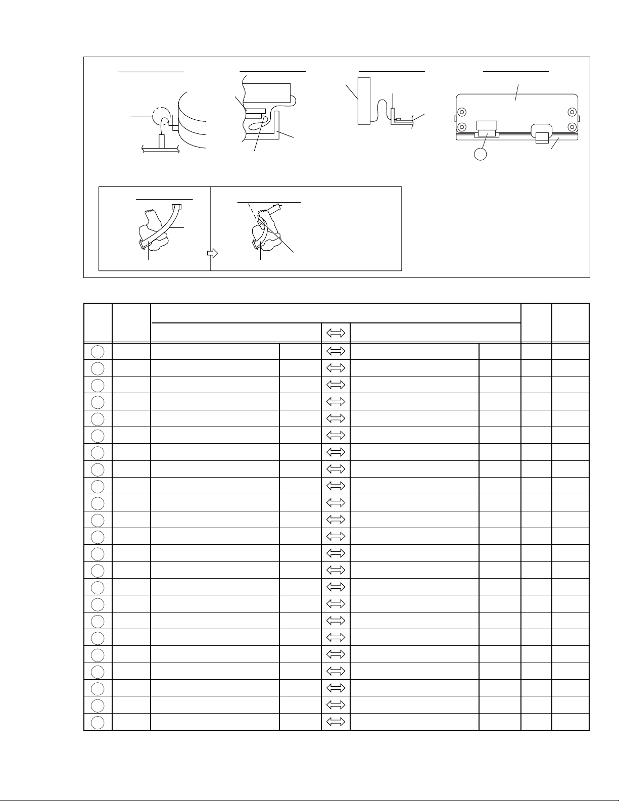
Page 4
Important Safety Precautions
cut close to connector
Prior to shipment from the factory, JVC products are strictly inspected to conform with the recognized product safety and electrical codes
of the countries in which they are to be sold. However, in order to maintain such compliance, it is equally important to implement the
following precautions when a set is being serviced.
v
Precautions during Servicing
1. Locations requiring special caution are denoted by labels and
inscriptions on the cabinet, chassis and certain parts of the
product. When performing service, be sure to read and comply with these and other cautionary notices appearing in the
operation and service manuals.
2. Parts identified by the
critical for safety.
Replace only with specified part numbers.
Note: Parts in this category also include those specified to com-
ply with X-ray emission standards for products using
cathode ray tubes and those specified for compliance
with various regulations regarding spurious radiation
emission.
3. Fuse replacement caution notice.
Caution for continued protection against fire hazard.
Replace only with same type and rated fuse(s) as specified.
4. Use specified internal wiring. Note especially:
1) Wires covered with PVC tubing
2) Double insulated wires
3) High voltage leads
5. Use specified insulating materials for hazardous live parts.
Note especially:
1) Insulation Tape 3) Spacers 5) Barrier
2) PVC tubing 4) Insulation sheets for transistors
6. When replacing AC primary side components (transformers,
power cords, noise blocking capacitors, etc.) wrap ends of
wires securely about the terminals before soldering.
symbol and shaded ( ) parts are
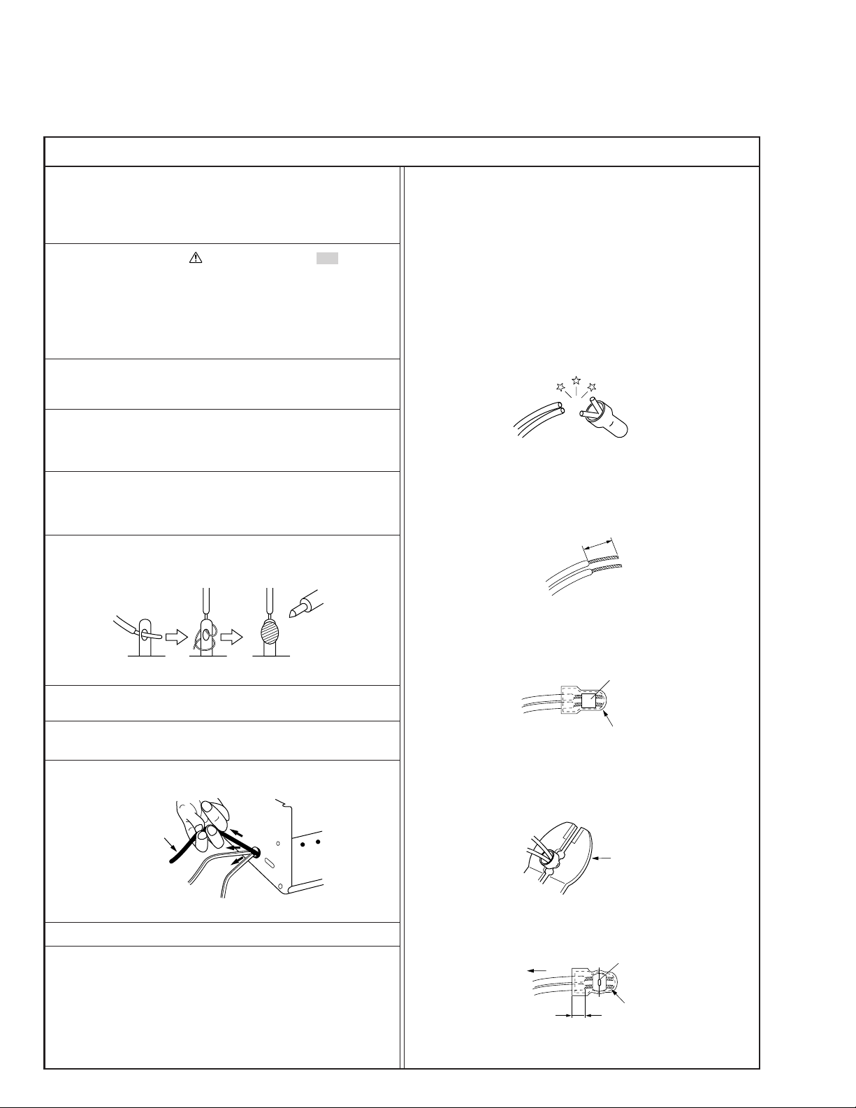
12. Crimp type wire connector
In such cases as when replacing the power transformer in sets
where the connections between the power cord and power
transformer primary lead wires are performed using crimp type
connectors, if replacing the connectors is unavoidable, in order to prevent safety hazards, perform carefully and precisely
according to the following steps.
1) Connector part number : E03830-001
2) Required tool : Connector crimping tool of the proper type
which will not damage insulated parts.
3) Replacement procedure
(1) Remove the old connector by cutting the wires at a point
close to the connector.
Important : Do not reuse a connector (discard it).
Fig.3
(2) Strip about 15 mm of the insulation from the ends of
the wires. If the wires are stranded, twist the strands to
avoid frayed conductors.
15 mm
Fig.1
7. Observe that wires do not contact heat producing parts
(heatsinks, oxide metal film resistors, fusible resistors, etc.)
8. Check that replaced wires do not contact sharp edged or
pointed parts.
9. When a power cord has been replaced, check that 10-15 kg of
force in any direction will not loosen it.
Power cord
Fig.2
10. Also check areas surrounding repaired locations.
11. Products using cathode ray tubes (CRTs)
In regard to such products, the cathode ray tubes themselves,
the high voltage circuits, and related circuits are specified for
compliance with recognized codes pertaining to X-ray emission.
Consequently, when servicing these products, replace the cathode ray tubes and other parts with only the specified parts.
Under no circumstances attempt to modify these circuits.
Unauthorized modification can increase the high voltage value
and cause X-ray emission from the cathode ray tube.
Fig.4
(3) Align the lengths of the wires to be connected. Insert
the wires fully into the connector.
Metal sleeve
Connector
Fig.5
(4) As shown in Fig.6, use the crimping tool to crimp the
metal sleeve at the center position. Be sure to crimp fully
to the complete closure of the tool.
1.25
2.0
5.5
Fig.6
(5) Check the four points noted in Fig.7.
Not easily pulled free
Wire insulation recessed
more than 4 mm
Fig.7
Crimping tool
Crimped at approx. center
of metal sleeve
Conductors extended
1
S40888-01
Page 5
v
d'
d
Chassis
Power cord,
primary wire
Safety Check after Servicing
Examine the area surrounding the repaired location for damage or deterioration. Observe that screws, parts and wires have been
returned to original positions, Afterwards, perform the following tests and confirm the specified values in order to verify compliance with safety standards.
1. Insulation resistance test
Confirm the specified insulation resistance or greater between power cord plug prongs and
externally exposed parts of the set (RF terminals, antenna terminals, video and audio input
and output terminals, microphone jacks, earphone jacks, etc.). See table 1 below.
2. Dielectric strength test
Confirm specified dielectric strength or greater between power cord plug prongs and exposed
accessible parts of the set (RF terminals, antenna terminals, video and audio input and output
terminals, microphone jacks, earphone jacks, etc.). See table 1 below.
3. Clearance distance
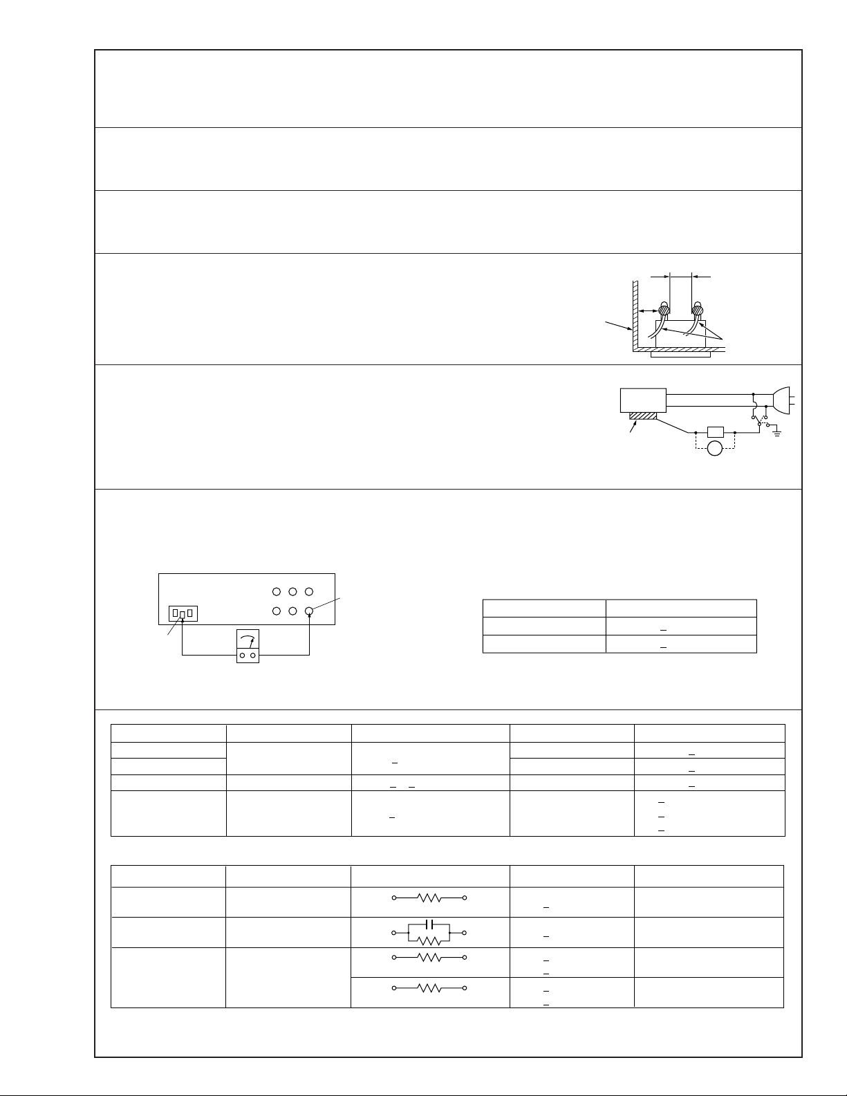
When replacing primary circuit components, confirm specified clearance distance (d), (d’) between soldered terminals, and between terminals and surrounding metallic parts. See table 1
below.
Fig. 8
4. Leakage current test
Confirm specified or lower leakage current between earth ground/power cord plug prongs
and externally exposed accessible parts (RF terminals, antenna terminals, video and audio
input and output terminals, microphone jacks, earphone jacks, etc.).
Measuring Method : (Power ON)
Insert load Z between earth ground/power cord plug prongs and externally exposed accessible parts. Use an AC voltmeter to measure across both terminals of load Z. See figure 9 and
following table 2.
Externally
exposed
accessible part
Z
V
Fig. 9
ab
c
5. Grounding (Class 1 model only)
Confirm specified or lower grounding impedance between earth pin in AC inlet and externally exposed accessible parts (Video in,
Video out, Audio in, Audio out or Fixing screw etc.).
Measuring Method:
Connect milli ohm meter between earth pin in AC inlet and exposed accessible parts. See figure 10 and grounding specifications.
AC inlet
Earth pin
AC Line Voltage
100 V
100 to 240 V
110 to 130 V
110 to 130 V
200 to 240 V
Exposed accessible part
Milli ohm meter
Fig. 10
Region
Japan
USA & Canada
Europe & Australia R 10 MΩ/500 V DC
Region Load Z
Insulation Resistance (R)
≤
R 1 MΩ/500 V DC
≥≥
1 MΩ R 12 MΩ/500 V DC
≤
Table 1 Specifications for each region
Grounding Specifications
Region
USA & Canada
Europe & Australia
Dielectric Strength
AC 1 kV 1 minute
AC 1.5 kV 1 miute
AC 1 kV 1 minute
AC 3 kV 1 minute
AC 1.5 kV 1 minute
(Class 2)
(Class 1)
Grounding Impedance (Z)
≤
Z 0.1 ohm
≤
Z 0.5 ohm
Clearance Distance (d), (d')
≤
d, d' 3 mm
≤
d, d' 4 mm
≤
d, d' 3.2 mm
≤
d 4 mm
≤
d' 8 mm (Power cord)
≤
d' 6 mm (Primary wire)
a, b, cLeakage Current (i)AC Line Voltage
100 V
110 to 130 V
110 to 130 V
220 to 240 V
Note: These tables are unofficial and for reference only. Be sure to confirm the precise values for your particular country and locality.
Japan
USA & Canada
Europe & Australia
Table 2 Leakage current specifications for each region
1 kΩ
0.15 µF
1.5 kΩ
2 kΩ
50 kΩ
2
≤
i 1 mA rms Exposed accessible parts
≤
i 0.5 mA rms
≤
i 0.7 mA peak
≤
i 2 mA dc
≤
i 0.7 mA peak
≤
i 2 mA dc
Exposed accessible parts
Antenna earth terminals
Other terminals
S40888-01
Page 6

Page 7
SECTION 1
CONNECTOR
FPC
CONNECTOR
FPC
Fig. 1-3-1 Fig. 1-3-2
Fig. 1-3-3 Fig. 1-3-4
CONNECTOR
FPC
Fig. 1-3-5
CONNECTOR
FPC
CONNECTOR
FPC
DISASSEMBLY
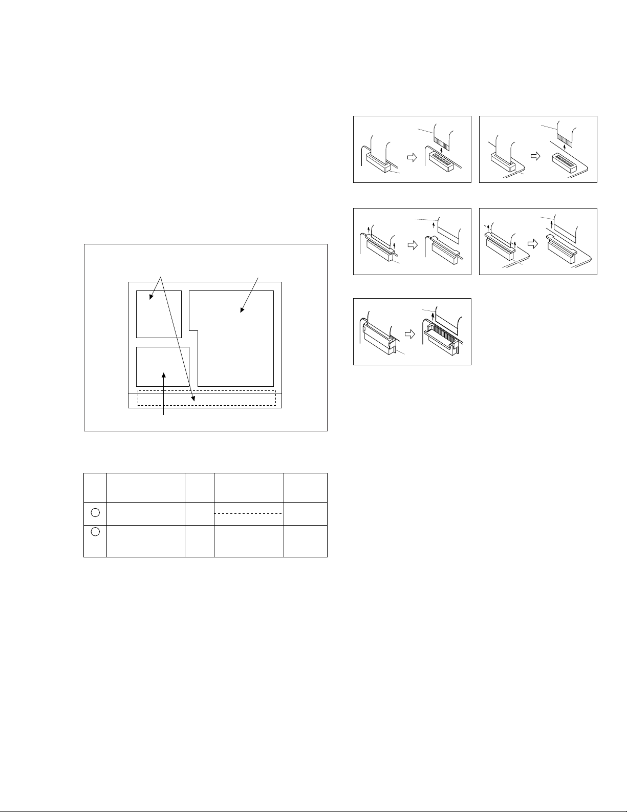
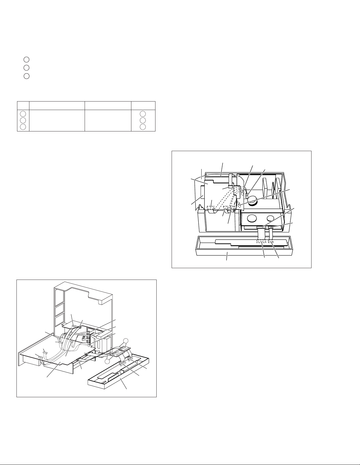
1.1 HOW TO REMOVE THE MAJOR PARTS
1.1.1 Introduction
This set is a double-deck video recorder integrating a Mini DV
deck and a VHS deck. Its internal structure is divided into three
sections that include the power supply, VHS and DV sections.
Therefore, the removal of major parts will also be described
under three separate sections as listed below.
1. COMMON section
2. VHS section
3. DV section
< TOP VIEW >
1. COMMON section
2. VHS section
1.3 DISCONNECTION OF CONNECTORS (WIRES)
3. DV section
Fig. 1-1-1
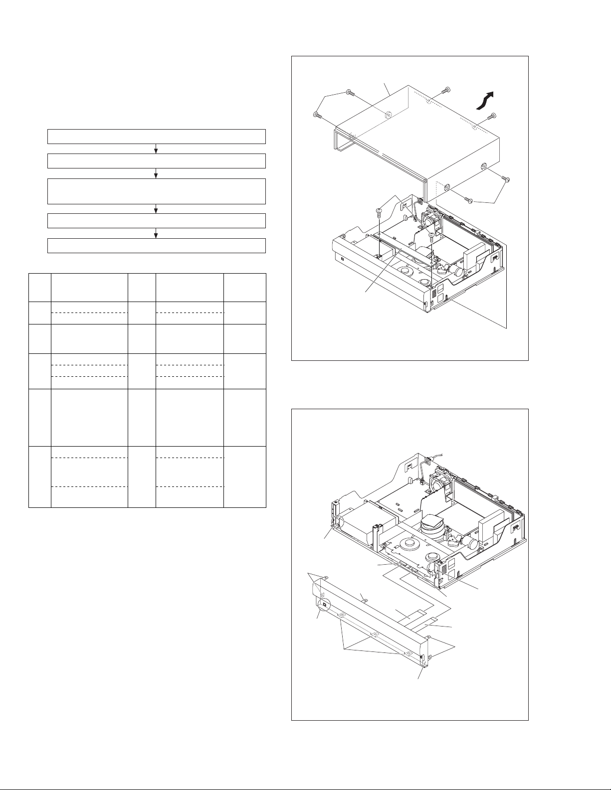
1.2 HOW TO READ THE DISASSEMBLY AND ASSEMBLY
Step/
Loc No.
1
Top cover, Bracket COM1
Front panel
2
assembly
Fig. No.
COM2 8(L3),
§§ §§ §
(1) (2) (3) (4) (5)
(1) Order of steps in Procedure
When reassembling, perform the step(s) in the reverse order.
These numbers are also used as the identification (location) No.
of parts Figures.
(2) Part name to be removed or installed.
(3) Fig. No. showing procedure or part location.
(4) Identification of part to be removed, unhooked, unlocked,
released, unplugged, unclamped or unsoldered.
P= Spring, W= Washer, S= Screw, L= Locking tab, SD= Solder,
CN**(WR**)= Remove the wire (WR**) from the connector
(CN**).
Note:
• The bracketed ( ) WR of the connector symbol are as-
signed nos. in priority order and do not correspond to
those on the spare parts list.
(5) Adjustment information for installation
Point NotePart name
4(S1), 3(S2), 2(L1), (L2)
2(S3)
CN7507(WR1),
CN3011(WR2)
<Note
1,2,3,4>
—
1-1
Page 8
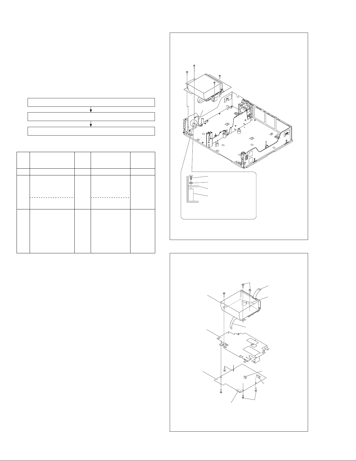
1.4
HOW TO REMOVE THE MAJOR PARTS <COM section>
1.4.1 Disassembly flow chart
This flowchart shows the disassembly procedure for the exterior parts and electrical parts.
Basically, reverse this procedure when assembling them.
[1] Top cover, Bracket
[2] Front panel assembly
(S1a)
[1] Top cover
(S1b)
(S1b)
SW/Display board assembly, Power SW board assembly,
[3]
Jog board assembly
[4] SW REG board assembly
Foot assembly, Foot(center), Foot(rear), Bottom cover
[5]
Disassembly/assembly method <COM section>
1.4.2
Step/
Loc No.
Top cover
[1]
Bracket
Front panel
[2]
assembly
SW/Display board assembly
[3]
Power SW board assembly
Jog board assembly
SW REG board
[4]
assembly
[5]
Foot assembly
Foot(center)
Foot(rear)
Bottom cover
Fig. No.
4(S1a), 2(S1b)
COM1
2(S1c)
COM2 8(L2a),
CN7510(WR2a),
CN3011(WR2b)
COM3 8(S3a)
2(S3b)
2(S3c),Knob(Jog)
COM4 4(S4a),
CN5322(WR4a),
CN5321(WR4b),
CN5325(WR4c),
CN5324(WR4d),
CN5323(WR4e)
COM5Lug wire
(S5a)
5(L5a)
4(L5b), 9(L5c),
2(L5d)
Point NotePart name
—
<Note 2a,
2b, 2c,2d>
—
<Note 2a>
<Note 5a>
<Note 2a>
• When attaching the FPC, be sure to connect it in the correct orientation.
• When attaching the FPC take care that it is not caught.
• When removing or attaching the WIRE/FPC, refer to "1.7
CONNECTION"(page 1-8) at same time.
<Note 2b>
When attaching the Front panel assembly, make sure that
the door openers of both decks (DV, VHS) are in the down
position.
<Note 2c>
When attaching the Front panel assembly, be careful not
to damage the DV terminals.
<Note 2d>
When attaching (WR2a) and (WR2b), insert supporting
long side to connector in the Main board assembly.
<Note 3a>
When attaching Jog board assembly, attach it before SW/
Display board assembly.
<Note 5a>
When removing Bottom cover, remove it after VHS section parts and DV section parts.
<Note 2b>
DV SIDE
(L2a)
DV terminals
<Note 2c>
(L2a)
(S1c)
[1] Bracket
Fig. COM1
CN3011
(L2a)
(WR2b)
<Note 2a, 2b>
[2] Front panel assembly
Fig. COM2
<Note 2b>
CN7510
VHS SIDE
(WR2a)
<Note 2a, 2d>
(L2a)
(S1a)
1-2
Page 9
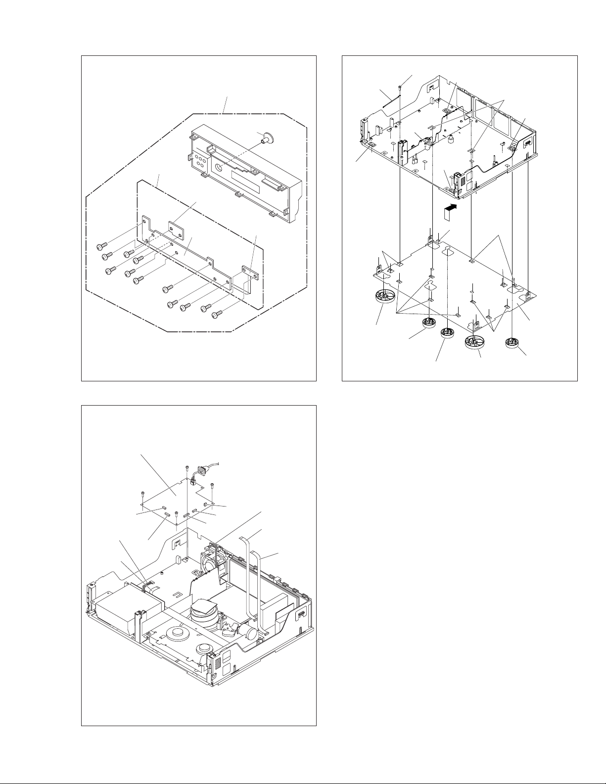
[2] Front panel assembly
Knob (Jog)
[5] Lug wire
(S5a)
(L5a)
(L5a)
(L5d)
(L5a)
(S3a)
(S3a)
(S3c)
(S3a)
(S3c)
(S3a)
(S3a)
[4] SW.REG board assy
(S3a)
(S3a)
[3]
(S3a)
(S4a)
Jog board assembly
<Note 3a>
SW/Display board
assembly
(S3b)
(S3b)
Fig. COM3
Power SW board
assembly
(L5a)
(L5b)
[5] Foot assy
(L5c)
[5] Foot(center)
[5] Foot(rear)
(L5a)
(L5b)
[5] Foot assy
Fig. COM5
(L5c)
(L5b)
[5] Bottom cover
(L5c)
[5] Foot(rear)
CN5324
(WR4d)
<Note 2a>
(WR4e)
<Note 2a>
(S4a)
CN5323
(S4a)
Fig. COM4
(S4a)
CN5325
CN5322
CN5321
(WR4c)
<Note 2a>
(WR4a)
<Note 2a>
(WR4b)
<Note 2a>
1-3
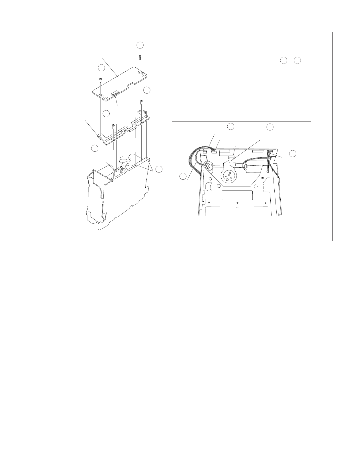
Page 10
1.5
HOW TO REMOVE THE MAJOR PARTS <VHS section>
1.5.1 Disassembly flow chart
This flowchart shows the disassembly procedure for the exterior parts and electrical parts.
Basically, reverse this procedure when assembling them.
However, it is required to remove the common section parts
as far as [1] “Top cover Bracket” and [2] “Front panel assembly” in advance. (See section 1.4.)
[1] Drum assembly
[2] Mechanism assembly
[3] Main board assembly
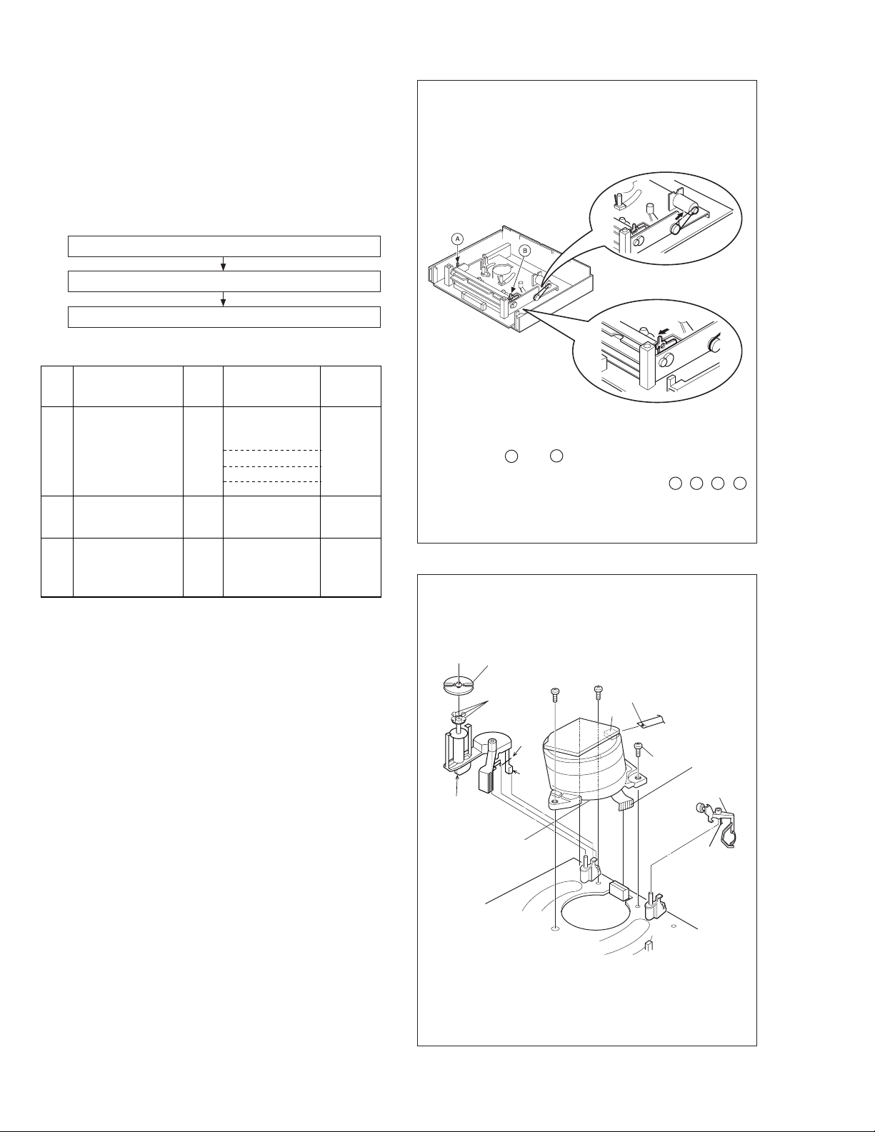
1.5.2 DIsassembly/assembly method <VHS section>
Procedures for Lowering the Cassette holder assembly
As the mechanism of this unit is integrated with the Housing
assembly, the holder must be lowered and the two screws unscrewed when removing the Mechanism assembly.
Fig. 2
Fig. 1
Step/
Loc No.
[1]
Drum assembly
(Inertia plate)
(Roller arm assy)
(Cleaner assy)
Mechanism
[2]
assembly
Main board
[3] <Note 1b>
assembly
Fig. No.
V1
V2
V3 (S8a), 6(L8a),
Point NotePart name
CN1(WR6a),
CON1(WR6b),
(S6a), (S6b), (S6c)
4(L6a)
(P6a), (L6b)
(L6c)
(S7a), (S7b), (S7c),
(S7d), 2(L7a),
CN1(WR7a)
CN701(WR8a),
CN2601(WR8b),
CN3014(WR8c)
<Note 1a,1b>
<Note 1b,
2a, 2b, 2c>
<Note 1a>
When attaching or removing the FPC, take care not to disconnect any of the wires.
<Note 1b>
• When attaching the FPC, be sure to connect it in the correct orientation.
• When removing or attaching the WIRE/FPC, refer to "1.7
CONNECTION"(page 1-8) at same time.
<Note 2a>
When it is required to remove the screws ((S7a), (S7b),
(S7c) and (S7d)) retaining the Mechanism assembly , please
refer to the “Procedures for Lowering the Cassette holder
assembly”(See on page 1-4).
<Note 2b>
• When reattaching the Mechanism assembly to the Main
board assembly, take care not to damage the sensors on
the Main board assembly (D3001: LED, Q3002: Start sensor, Q3003: End sensor, S3002: S cassette switch).
• When reattaching the Mechanism assembly to the Main
board assembly, CN2 of LOADING MOTOR BOARD
should not be floated.
Fig. 3
Turn the loading motor pulley in the direction as indicated by
Fig.2. As both A and B levers are lodged twice, push the
levers in the direction as indicated by Fig.3 to release them.
When pushing the levers, do it in the order of A , B , B , A .
When the holder has been lowered, turn the pulley until the
cassette holder is securely in place without allowing any up/
down movement.
Procedures for Lowering the Cassette holder assembly
Note: When installing the Drum assembly, secure the screws
(S6a to S6c) in the order of a, b, c.
Inertia plate
(S6c)
Roller arm
assy
(S6a)
(L6a)
(P6a)
(L6b)
[1]
Drum
assembly
CON1
CN1
(WR6b)
<Note 1b>
(S6b)
(WR6a)
<Note 1a,1b>
Cleaner assy
(L6c)
<Note 2c>
• When removing the Mechanism assembly only, unhook the
two spacers connecting it with the Main board assembly
with pliers from the back side of the Main board assembly
first, and then remove the Mechanism assembly.
1-4
Fig. V1
Page 11
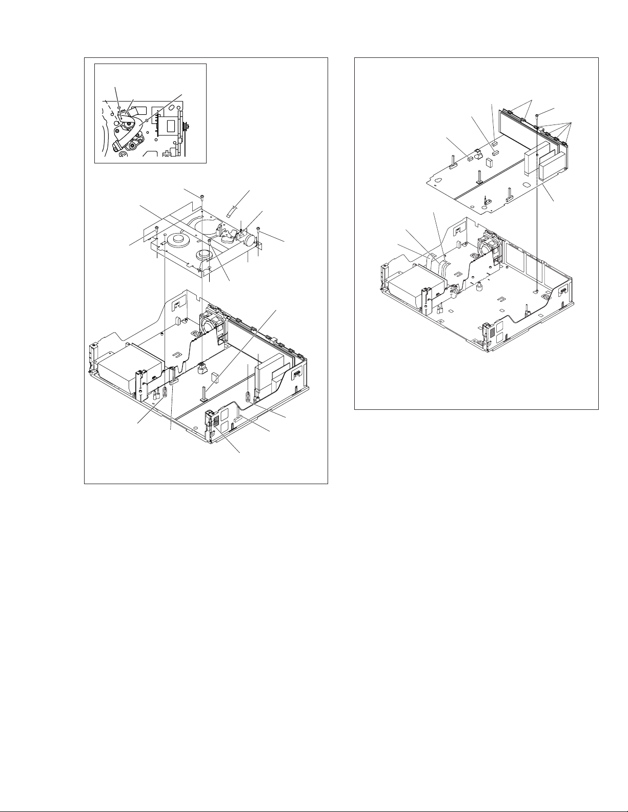
Note:
(S8a)
(L8a)
(L8a)
CN2601
CN701
CN3014
[3] Main board
assembly
(WR8a)
<Note 1b>
(WR8b)
<Note 1b>
(WR8c)
<Note 1b>
Make a crease on the position where
the dotted line is not exceeded.
A/C head base
(WR7a)
Note:
When installing the
Mechanism assembly,
secure the screws
(S7a to S7b) in the
order of a, b.
[2]
Mechanism
assembly
(S7b)
<Note 2a>
(L7a)
spacer
<Note 2c>
(S7d)
Q3003
Q3003
End sensor
<Note 2b>
D3001
(WR7a)
<Note 1b>
CN2
(S7a)
<Note 2a>
CN1
Q3002
S3002
S3002
S cassette switch
<Note 2b>
CN2
<Note 2b>
(S7c)
D3001
LED
<Note 2b>
<Note 2c>
Q3002
Start sensor
<Note 2b>
(L7a)
spacer
Fig. V3
Fig. V2
1-5
Page 12
1.6
HOW TO REMOVE THE MAJOR PARTS <DV section>
1.6.1 Disassembly flow chart
This flowchart shows the disassembly procedure for the exterior parts and electrical parts.
Basically, reverse this procedure when assembling them.
However, it is required to remove the common section parts
as far as [1] “Top cover, Bracket” and [2] “Front panel assembly” in advance. (See section 1.5.)
(S9b)
(S9a)
(S9a)
(S9a)
[1] Base(DV)
[2] DV Mechanisam assembly, DV Main board assembly
[3] DV MDA board assembly
1.6.2 Disassembly/assembly method <DV section>
Step/
Loc No.
[1]
[2]
[3]
Base(DV)
DV Mechanism
assembly
DV Main board
assembly
DV MDA board
assembly
Fig. No.
D1 3(S9a), (S9b)
D2 3(S10a),
D3 2(S11a), 2(S11b),
Point NotePart name
CN1502(WR10a),
CN4001(WR10b)
CN1501(WR10c)
4(S10b)
2(L11a),
CN5503(WR11a),
CN5504(WR11b),
CN5502(WR11c),
CN5505(WR11d),
CN5507(WR11e),
Bracket(MDA)
<Note 1a>
<Note 2a,
2b, 2c>
<Note 2c>
<Note 1a>
With due regard to operational considerations, remove the
parts located on the Base(DV) (i.e. DV Mechanism assembly, DV MDA board assembly etc.) together before removing the major parts.
<Note 2a>
Take care not to scratch or damage the drum assembly
by the cleaner assembly when performing work.
<Note 2b>
Take care not to damage the board assembly when detaching parts.
<Note 2c>
• When attaching the FPC, be sure to connect it in the correct orientation.
• When removing or attaching the WIRE/FPC, refer to "1.7
CONNECTION"(page 1-8) at same time.
Lug wire
(S9b)
Lug wire
Base(DV)
Bottom chassis
When reattaching (S9b), attach
in the order of the above figure.
Fig. D1
[2] Mechanism
assembly(DV)
<Note 2a>
[1] Base(DV)
[2] DV Main
board assembly
<Note 2b>
(S10a)
(S10b)
CN1502
(S10a)
(WR10a)
<Note 2c>
CN4001
(WR10c)
<Note 2c>
(WR10b)
<Note 2c>
CN4001
CN1501
1-6
(S10b)
CN1502
Fig. D2
(S10b)
Page 13
[3] DV MDA board assembly
5
(S11a)
CN5504
Bracket(DV)
(WR11b)
<Note 2c>
3
(S11b)
2
5
(S11a)
(S11b)
3
NOTE: When removing, remove in order of a number to .
CN5505
CN5503
1
4
(WR11a)
<Note 2c>
CN5507
3
(L11a)
(WR11d)
<Note 2c>
CN5502
1
(WR11c)
<Note 2c>
1
5
1
(WR11e)
<Note 2c>
Fig. D3
1-7
Page 14
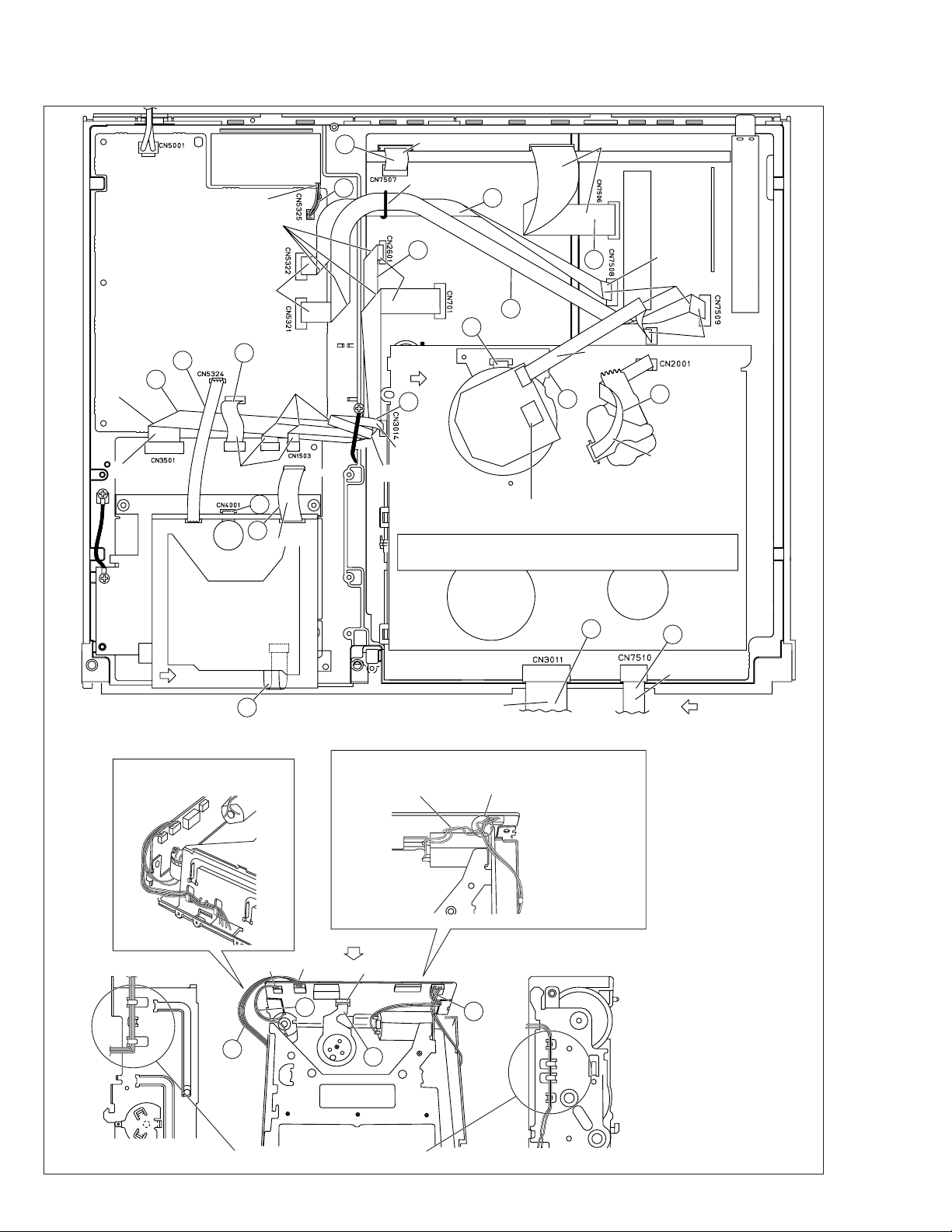
1.7 CONNECTION
Treat the wire so as not to come to fan.
right side
7
CN5323
CN1001
right side
bend
right side
6
11
CN5501
DV DRUM
FAN
bend
CN3701
18
14
bend
CN5506
back side
CN1501
16
right side
TERMINAL PWB
5
Hold wire by stylepin.
3
ST2
12
right side
CN502CN901
right side
15
right side
make a crease
4
8
CN1
right side
CN3001
right side
A
10
right side
A/C HEAD
bend
13
back side
DRUM
Should be confirmed that wire not
touch to IC of STATOR PWB ASS'Y.
9
B
17
NOTE) Wire the wires as
shown in a figure.
21
CN1502
CN5502
NOTE) Wire the wires as shown in a figure.
NOTE) Put the surplus
wire into this space.
"D"
CN5505
22
CN5503
19
CN5507
back side
To SW/Display board
CN7001
NOTE) Twist a wire one time.
20
2
To SW/Display board
CN7191
1
back side
C
1-8
NOTE) Wire the wires as shown in a figure.
Fig. 1-7-1
Page 15
DETAIL"A"
Absorb the looseness of
the wire in the B part.
B
CN1
MAIN PWB
WIRING for MECHA ADJ
DRUM
DETAIL"B"
DV MAIN
PWB
FINAL WIRING
DV MECHA
CN1502
electrode side
Push into the BOTTOM CHASSIS
and treat the wire according
to the following figure.
BOTTOM
CHASSIS
DETAIL"C"
FRONT
PANEL
Absorb the looseness of the wire
according to the following figure.
BOTTOM CHASSIS
CN7510
MAIN PWB
CN3011
DETAIL "D"
DV MDA BOARD ASSEMBLY
CN5504
23
BRACKET(DV)
AC/ HEAD
right side
(WR7a)
AC/ HEAD
right side
After MECHA adjustment,
Treat the wire (WR7a) according
to the following figure.
Make a crease on the position where
the dotted line is not exceeded.
Fig. 1-7-2
Fig
No.
Symbol
Connected point
Connection
Connected point
Pin
No.
Type
(FPC/
WIRE)
1 WR2a MAIN CN7510 SW/DISPLAY CN7191 10 FPC
2 WR2b MAIN CN3011 SW/DISPLAY CN7001 20 FPC
3 WR4a MAIN CN7508 SW/REG CN5322 10 FPC
4 WR4b MAIN CN7509 SW/REG CN5321 12 FPC
5 WR4c SW/REG CN5325 FAN MOTOR - 2 WIRE
6 WR4d SW/REG CN5324 DV MDA CN5501 5 WIRE
7 WR4e SW/REG CN5323 DV MAIN CN1001 8 FPC
8 WR6a MAIN CN1 UPPER DRUM - 13 FPC
9 WR6b DRUM MOTOR CON1 MAIN CN3001 5 FPC
10 WR7a A/C HEAD CN1 MAIN CN2001 7 FPC
11 WR8a MAIN CN701 DV MAIN CN3501 14 FPC
12 WR8b MAIN CN2601 DV MAIN CN3701 8 FPC
13 WR8c MAIN CN3014 DV MAIN CN1503 4 FPC
14 WR10c DV MAIN CN1501 DV MDA CN5506 20 FPC
15 - MAIN CN7506 TERMINAL CN502 15 FPC
16 - MAIN CN7507 TERMINAL CN901 5 FPC
17 WR10a SENSOR(DV) - DV MAIN CN1502 15 FPC
18 WR10b PRE/REC(DRUM)(DV) - DV MAIN CN4001 8 FPC
19 WR11a DRUM MOTOR(DV) - DV MDA CN5503 11 FPC
20 WR11e HOUSING MOTOR(DV) - DV MDA CN5507 4 WIRE
21 WR11d ROTARY ENCODER(DV) - DV MDA CN5505 4 WIRE
22 WR11c LOADING MOTOR(DV) - DV MDA CN5502 2 WIRE
23 WR11b CAPSTAN MOTOR(DV) - DV MDA CN5504 18 FPC
Table 1-7-1
1-9
Page 16
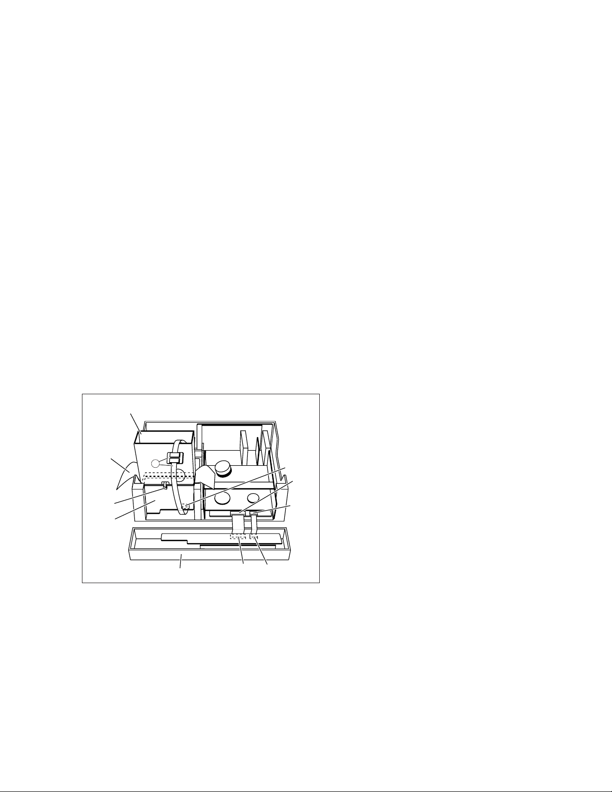
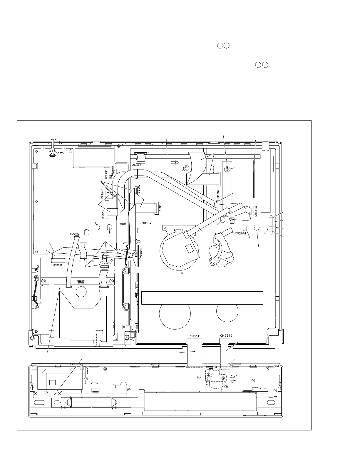
1.8 SERVICE POSITIONS
The servicing locations for use in troubleshooting or servicing of the set are provided separately for the VHS and DV.
I SERVICE POSITIONS <VHS SIDE>
II SERVICE POSITIONS <DV FOIL SIDE>
III SERVICE POSITIONS <DV COMPONENT SIDE>
1.8.1 Requirement PATCH CORDS
The following PATCH CORDS is required.
Board to Board Wire Used
1 PTU94022-10 QUQ212-1040CG I
2 PTU94022-20 QUQ112-2040CG I
3 YTU94074-15 QUQ105-1540AA III
Table 1-8-1
1.8.2 Service position <VHS SIDE>
<Removal>
(1) Remove the top cover and bracket.
(2) Remove the front panel assembly.
(3) Remove the Main board assembly together with the
Mechanism assembly.
< Installation >
(1) Stand up the Bottom chassis assembly so that the DV/
Regulator side is in the lower position.
Note: • Take care to the fall of the Fan.
(2) Connect FPCs and wires accordingly in Fig. 1-8-1.
Point: • Take care that the FPCs and wires are not
subjected to stress in this positioning.
(3) Connect the PATCH CORDS to the two FPCs of the Front
panel assembly, then connect the CORDS to the
CN7510/CN3011.
For the PATCH CORD is required, see Table 1-8-1.
1.8.3 Service position <DV FOIL SIDE>
<Removal>
(1) Remove the top cover and bracket.
(2) Remove the front panel assembly.
(3) Remove the Base(DV) together with DV Mechanism as-
sembly and DV Main board assembly.
Note:
• Take care not to damage the parts during operating.
< Installation >
(1) Place an insulation sheet on the SW/Reg board assem-
bly.
(2) Place a DV section(Base(DV) with DV Mechanism as-
sembly and DV Main board assembly) on the insulation
sheet.(refer to Fig. 1-8-2)
Note:
• Confirm that FPCs and wires are not unconnected from
the connectors.
DV Mechanism
Insulation Sheet
assembly
DV Main board
assembly
CN1502
CN3501
Base(DV)
CN3701
CN1503
Front panel assembly
CN2601
CN701
CN7001
CN3014
CN3011
CN7510
CN7191
Fig. 1-8-2
CN2601
CN7509
Main board assembly
1-10
CN701
CN7508
CN5322
CN3011
CN3014
CN5321
CN7510
Fig. 1-8-1
CN1503
CN3701
CN3501
1
2
CN7191
CN7001
Front panel assembly
Page 17
1.8.4 Service position <DV COMPONENT SIDE>
<Removal>
(1) Remove the top cover and bracket.
(2) Remove the front panel assembly.
(3) Remove the Base(DV) together with DV Mechanism as-
sembly and DV Main board assembly.
(4) Remove the DV Mechanism assembly and DV Main
board assembly from Base(DV).
Note:
• Take care not to damage the parts during operating.
< Installation >
(1) Place a DV Main board assembly on the Bottom chas-
sis.
(2) Place an insulation sheet on the rear side of DV Main
board assembly.
(3) Place a DV Mechanism assembly on the insulation sheet.
Note:
• Confirm that DV Mechanism assembly be getting on on
the insulation sheet completely.
(4) Connect PATCH CORD to the connector(CN1502) and
connect FPC from DV Mechanism assembly.(refer to Fig.
1-8-3)
(5) Connect other FPCs and wires to the connector that cor-
responds each.(refer to "1-7 CONNECTION")
For the PATCH CORD is required, see Table 1-8-1.
Note:
• Confirm that FPCs and wires are not unconnected from
the connectors(especially CN4001).
1.9 Jig RCU mode
This unit uses the following two modes for receiving remote
control codes.
1) User RCU mode : Ordinary mode for use by the user.
2) Jig RCU mode : Mode for use in production and servicing.
When using the Jig RCU, it is required to set the VCR to the Jig
RCU mode (the mode in which codes from the Jig RCU can be
received). As both of the above two modes are stored in the
EEPROM, it is required to set the VCR back to the User RCU
mode each time that an adjustment is made or to check that the
necessary operations have been completed. These modes can be
set by the operations described below.
1.9.1 Setting the Jig RCU mode
(1) Unplug the power cord plug from the power outlet.
(2) Press and hold the “REC” and “PAUSE” buttons on the
VCR simultaneously, while plugging the power cord plug
into the power outlet.
When the VCR is set to the Jig RCU mode, the symbols
( “ : ” ) in the time display of the FDP are turned off.
1.9.2 Setting the User RCU mode
(1) Turn off the power.
(2) Press the “REC” and “PAUSE” buttons of the VCR simul-
taneously. Alternatively, transmit the code “80” from the
Jig RCU.
DV Mechanism
assembly
Insulation Sheet
CN4001
DV Main board
assembly
3
Front panel assembly
Fig. 1-8-3
CN7001
CN1502
CN3011
CN7510
CN7191
1-11
Page 18
1.10 MECHANISM SERVICE MODE
This model has a unique function to enter the mechanism
into every operation mode without loading of any cassette
tape. This function is called the “MECHANISM SERVICE
MODE”.
1.10.1 How to set the "MECHANISM SERVICE MODE"
(1) Disconnect VCR from AC.
(2) Connect TPGND and TP7001 (TEST) on the Display
board assembly with a jump wire.
(3) Connect VCR to AC.
(4) Press the POWER button.
(5) With lock levers A B on the left and right of the Cassette
holder assembly pulled toward the front, slide the holder
in the same direction as the cassette insertion direction.
(For the positions of lock levers A B , refer to the “Procedures for Lowering the Cassette holder assembly” on
page 1-4 of 1.5 HOW TO REMOVE THE MAJOR PARTS
<VHS section>
(6) The cassette holder lowers and, when the loading has
completed, the mechanism enters the desired mode.
bend
right side
DV MAIN BOARD
ASSEMBLY
SW/REG BOARD
ASSEMBLY
CP5321
CN1001
right side
CN5501
DV DRUM
FAN
right side
CP5322
CN5323
CN3701
bend
back side
CP5325
bend
CN5506
CN2001
(JIG CONN.)
CN1501
TERMINAL BOARD ASSEMBLY
right side
TP701
D YV IN
ST2
right side
MAIN BOARD
ASSEMBLY
DRUM
back side
bend
3D DIGITAL/2M BOARD ASSEMBLY
VR701
D YV IN
CN1
CN502CN901
right side
CP3004
right side
VR1401
D/A LEVEL
ADJ
right side
make a crease
CN3001
right side
A/C HEAD
DEMOD BOARD
ASSEMBLY
right side
CP4001
CP3003
TP111
D.FF
TP4001
CTL. P
TP106
PB. FM
TP2253
A. PB.FM
1-12
DV MDA BOARD
ASSEMBLY
FW7002
DV MECHANISM
ASSEMBLY
POWER SW BOARD
ASSEMBLY
CN1502
FW7001
back side
SW/DISPLAY BOARD ASSEMBLY
<FRONT PANEL ASSEMBLY>
Fig. 1-10-1
VHS MECHANISM ASSEMBLY
JOG BOARD
CN7001
CN7191
back side
ASSEMBLY
TPGND
TP7001
TEST
Page 19
1.11 Emergency display function
This unit has a function for storing the history of the past two
emergencies (EMG) and displaying them on each FDP (or
OSD). With the status of the VCR and mechanism at the moment an emergency occurred can also be confirmed.
FDP display model
[FDP display]
0: 00 : 00
E:**:**
*1: *2 : 34
*5: *6 :*7
FDP (7segment LED) display model
[FDP display]
0: 00
E: **
1: **
2: *1
3: *2
4: 34
5: *5
6: *6
7: *7
OSD display model
[OSD display]
Normal display
EMG content display
(E:Latest:Previous)
EMG detail information <1>
EMG detail information <2>
Normal display
EMG content display (Latest)
EMG content display (Previous)
EMG detail information <1>
[Deck operation mode]
EMG detail information <1>
[Mechanism operation mode]
EMG detail information <1>
[Mechanism sensor information and Mechanism mode position]
EMG detail information <2>
[Type of the cassette tape in use <1>]
EMG detail information <2>
[Winding position of the cassette tape in use]
EMG detail information <2>
[Type of the cassette tape in use <2> (Winding area)]
EMG
E:**:**
*1: *2 : 34
*5: *6 :*7
EMG content display
(E:Latest:Previous)
EMG detail information <1>
EMG detail information <2>
Notes:
• The EMG detail information <1><2> show the information
on the latest EMG.
It becomes “ – – : – – : – –” when there is no latest EMG
record.
• When using the Jig RCU, it is required to set the VCR to
the Jig RCU mode (the mode in which codes from the Jig
RCU can be received).
Jig RCU
[Data transmitting method]
Depress the “ ” ( 3 ) button
after the data code is set.
CUSTOM CODE
43: A CODE
DATA CODE
INITIAL MODE
Fig. 1-11a Jig RCU [PTU94023B]
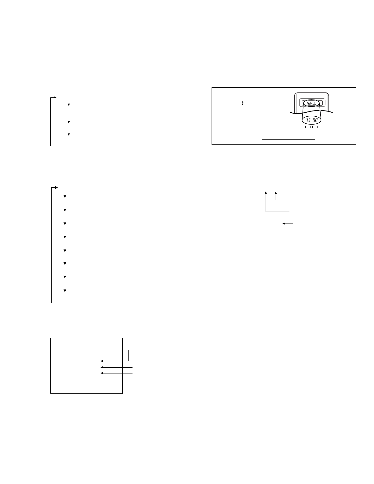
1.11.1 Displaying the EMG information
(1) Transmit the code “59” from the Jig RCU.
The FDP shows the EMG content in the form of “E:**:**”.
<Example 1> E : 01 : 03
Previous EMG
Latest EMG
<Example 2> E : –– : – –
No EMG record
(2) Transmit the code “59” from the Jig RCU again.
The FDP shows the EMG detail information <1> in the form
of “ *1: *2 : 34 ”.
*1 : Deck operation mode at the moment of EMG
*2 : Mechanism operation mode at the moment of EMG
3– : Mechanism sensor information at the moment of
EMG
–4 : Mechanism mode position at the moment of EMG
(3) Transmit the code “59” from the Jig RCU once again.
The FDP shows the EMG detail information <2> in the form
of “ *5 : *6 : *7 ”.
*5 : Type of the cassette tape in use <1> .
*6 : Winding position of the cassette tape in use
*7 : Type of the cassette tape in use <2> (Winding area)
(4) Transmit the code “59” from the Jig RCU once again to re-
set the display.
Notes:
• For the OSD display model, all EMG information are
showed by transmitting first code from the Jig RCU.
• For the EMG content, see “1.7.3 EMG content description”.
• For the EMG detail information <1> , see “1.7.4 EMG detail information <1> ”.
• For the EMG detail information <2> , see “1.7.5 EMG de-
tail information <2>”.
1.11.2 Clearing the EMG history
(1) Display the EMG history.
(2) Transmit the code “36” from the Jig RCU.
(3) Reset the EMG display.
(EMG-02e)
1-13
Page 20

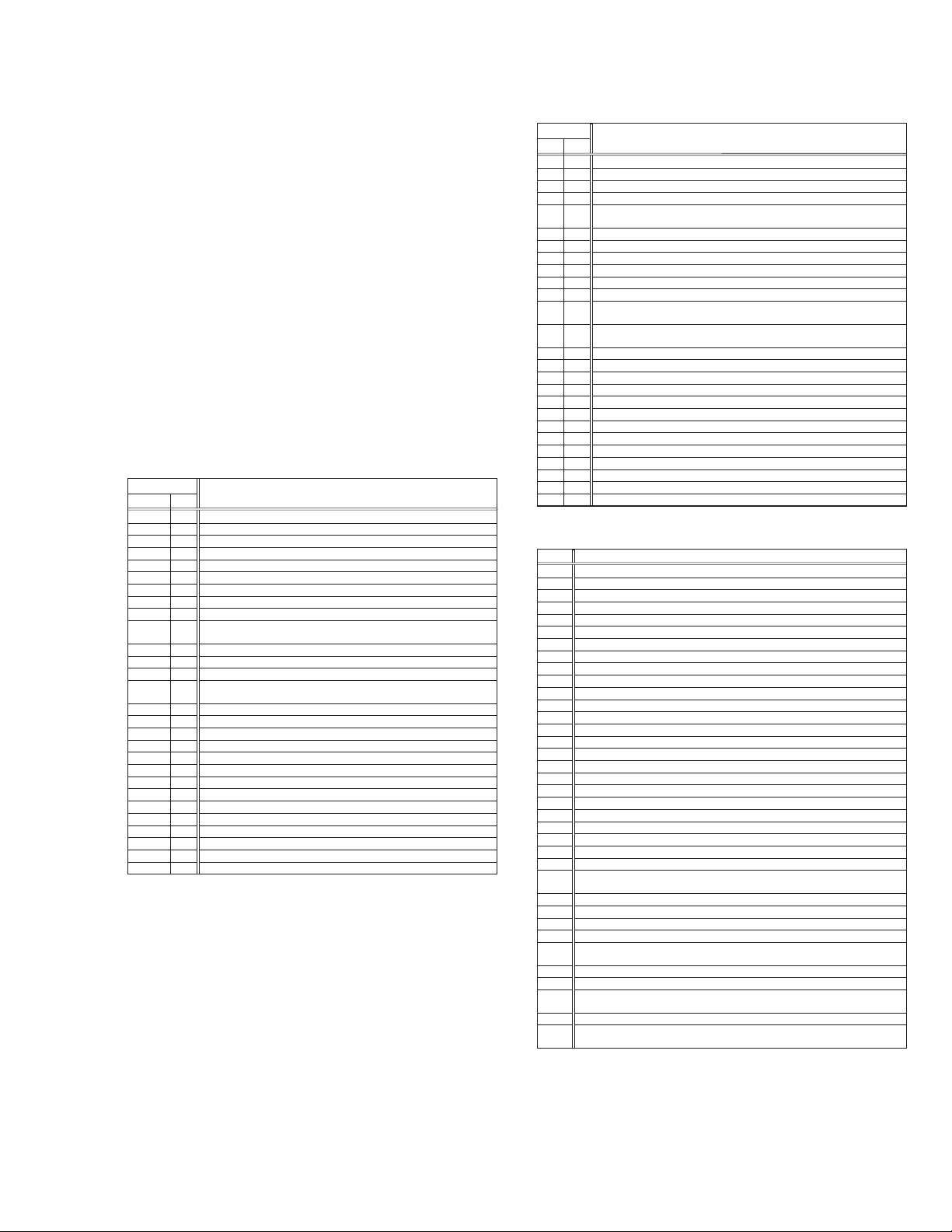
1.11.3 EMG content description
Note: EMG contents “E08/E09” are for the model with Dynamic Drum (DD).
FDP CONTENT CAUSE
E01:Loading EMG
E02:
Unloading EMG
E03:Take Up Reel
Pulse EMG
E04: Drum FG
EMG
E05:Cassette Eject
EMG
E06:Capstan FG
EMG
E07:SW Power
Short-Circuit
EMG
E08:
DD Initialized
(Absolute
Position
Sensor)
EMG
E09: DD FG EMG
E0A:Supply Reel
Pulse EMG
EC1 or EU1:
Head clog warning
When the mechanism mode cannot be changed to another mode even when the loading motor has rotated
for more than 4 seconds in the loading direction, [E:01]
is identified and the power is turned off.
When the mechanism mode cannot be changed to another mode even when the loading motor has rotated
for more than 4 seconds in the unloading direction, [E:02]
is identified and the power is turned off.
When the take-up reel pulse has not been generated for
more than 4 seconds in the capstan rotating mode, [E:03]
is identified, the pinch rollers are turned off and stopped,
and the power is turned off. However, the reel EMG is
not detected in STILL/SLOW modes.
When the drum FG pulse has not been input for more
than 3 seconds in the drum rotating mode, [E:04] is identified, the pinch rollers are turned off and stopped, and
the power is turned off.
When the eject operation does not complete in 3 seconds after the start, [E:05] is identified, the pinch rollers
are turned off and stopped, and the power is turned off.
When the cassette insertion operation does not complete
in 3 seconds after the start, the cassette is ejected. In
addition, when the operation does not complete within
3 seconds after the start, [E:05] is also identified and the
power is turned off immediately.
When the capstan FG pulse has not been generated for
more than 1 second in the capstan rotating mode, [E:06]
is identified, the pinch rollers are turned off and stopped,
and the power is turned off.However, the capstan EMG
is not detected in STILL/SLOW/FF/REW modes.
When short-circuiting of the SW power supply with GND
has lasted for 0.5 second or more, [E:07] is identified,
all the motors are stopped and the power is turned off.
When DD tilting does not complete in 4 seconds, [E:08]
is identified, the tilt motor is stopped and the power is
turned off.
When the DD FG pulse is not generated within 2.5 seconds, [E:09] is identified, the tilt motor is stopped and
the power is turned off.
When the supply reel pulse has not been generated for
more than 10 seconds in the capstan rotating mode,
[E:0A] is identified and the cassette is ejected (but the
power is not turned off). However, note that the reel EMG
is not detected in the SLOW/STILL mode.
Presupposing the presence of the control pulse output in the PLAY mode, when the value obtained by mixing the two V.FM output
channels (without regard to the A.FM output) has remained below a certain threshold level for more than 10 seconds, [E:C1] or [E:U1]
is identified and recorded in the emergency history. During the period in which a head clog is detected, the FDP and OSD repeat the
“3-second warning display” and “7-second noise picture display” alternately.
EMG code : “E:C1” or “E:U1” / FDP : “U:01” / OSD : “Try cleaning tape.” or “Use cleaning cassette.”
The head clog warning is reset when the above-mentioned threshold has been exceeded for more than 2 seconds or the mode is
changed to another mode than PLAY.
The mechanism is locked in the middle of mode transition.
1.
2
. The mechanism is locked at the loading end due to the encoder position
reading error during mode transition.
3.
Power is not supplied to the loading MDA.
1.
The mechanism is locked in the middle of mode transition.
2.
The mechanism is locked at the unloading end due to the encoder position reading error during mode transition.
3.
Power is not supplied to the loading MDA.
1.
The take-up reel pulse is not generated in the FWD transport modes (PLAY/
FWD SEARCH/FF, etc.) because;
1) The idler gear is not meshed with the take-up reel gear;
The idler gear is meshed with the take-up reel gear, but incapable of wind-
2)
ing due to too large mechanical load (abnormal tension);
3) The take-up reel sensor does not output the FG pulse.
2.
The supply reel pulse is not generated in the REV transport modes (REV
SEARCH/REW, etc.) because;
1) The idler gear is not meshed with the supply reel gear.
2) The idler gear is meshed with the supply reel gear, but incapable of wind-
ing due to too large a mechanical load (abnormal tension);
3) The supply reel sensor does not output the FG pulse.
3.
Power is not supplied to the reel sensors.
1.
The drum could not start or the drum rotation has stopped due to too large
a load on the tape, because;
1) The tape tension is abnormally high;
The tape is damaged or a foreign object (grease, etc.) adheres to the tape.
2)
2.
The drum FG pulse did not reach the System controller CPU because;
1) The signal circuit is disconnected in the middle;
2) The FG pulse generator (hall device) of the drum is faulty.
3.
The drum control voltage (DRUM CTL V) is not supplied to the MDA.
4.
Power is not supplied to the drum MDA.
1.
The cassette cannot be ejected due to a failure in the drive mechanism of
the housing.
2.
When the housing load increases during ejection, the loading motor is
stopped because of lack of headroom in its drive torque.
Housing load increasing factors: Temperature environment (low temperature, etc.), mechanism wear or failure.
3.
The sensor/switch for detecting the end of ejection are not functioning normally.
4.
The loading motor drive voltage is lower than specified or power is not supplied to the motor (MDA).
5.
When the user attempted to eject a cassette, a foreign object (or perhaps
the user's hand) was caught in the opening of the housing.
1.
The capstan could not start or the capstan rotation has stopped due to too
large a load on the tape, because;
1) The tape tension is abnormally high (mechanical lock);
2) The tape is damaged or a foreign object (grease, etc.) is adhered to the
tape (occurrence of tape entangling, etc.).
2.
The capstan FG pulse did not reach the System controller CPU because;
1) The signal circuit is disconnected in the middle;
2) The FG pulse generator (MR device) of the capstans is faulty.
3.
The capstan control voltage (CAPSTAN CTL V) is not supplied to the MDA.
4.
Power is not supplied to the capstan MDA.
1.
The SW 5 V power supply circuit is shorted with GND.
2.
The SW 12 V power supply circuit is shorted with GND.
1. The absolute value sensor is defective. (The soldered parts have separated.)
2. The pull-up resistor at the absolute sensor output is defective. (The soldered parts
have separated.)
3. Contact failure or soldering failure of the pins of the connector (board-to-board) to the
absolute value sensor.
The absolute value sensor data is not sent to the System Controller CPU.
4.
1. The FG sensor is defective. (The soldered parts have separated.)
2. The pull-up resistor at the FG sensor output is defective. (The soldered parts have
separated.)
3. Contact failure or soldering failure of the pins of the connector (board-to-board) to the FG sensor.
4. The power to the sensor is not supplied. (Connection failure/soldering failure)
5. The FG pulse is not sent to the System Controller CPU.
The tilt motor is defective. (The soldered parts have separated.)
6.
7. The drive power to the tilt motor is not supplied. (Connection failure/soldering failure)
8. The tilt motor drive MDA - IC is defective.
9. Auto-recovery of the DD tilting cannot take place due to overrun.
The supply reel pulse is not generated in the FWD transport mode (PLAY/
1.
FWD SEARCH/FF, etc.) because;
1) PLAY/FWD or SEARCH/FF is started while the tape in the inserted cas-
sette is cut in the middle;
2) A mechanical factor caused tape slack inside and outside the supply
reel side of the cassette shell. In this case, the supply reel will not rotate
until the tape slack is removed by the FWD transport, so the pulse is not
generated until then;
3) The FG pulse output from the supply reel sensor is absent.
2.
The take-up reel pulse is not generated in the REV transport mode (REV
SEARCH/REW, etc.).
1) REV SEARCH/REW is started when the tape in the inserted cassette
has been cut in the middle;
2) A mechanical factor caused tape slack inside and outside the take-up
reel side of the cassette shell. In this case, the supply reel will not rotate
until the tape slack is removed by the REV transport, so the pulse will
not be generated until that time;
3) The FG pulse output from the take-up reel sensor is absent.
3.
The power to a reel sensor is not supplied.
1-14
Table 1-11-3a
Page 21
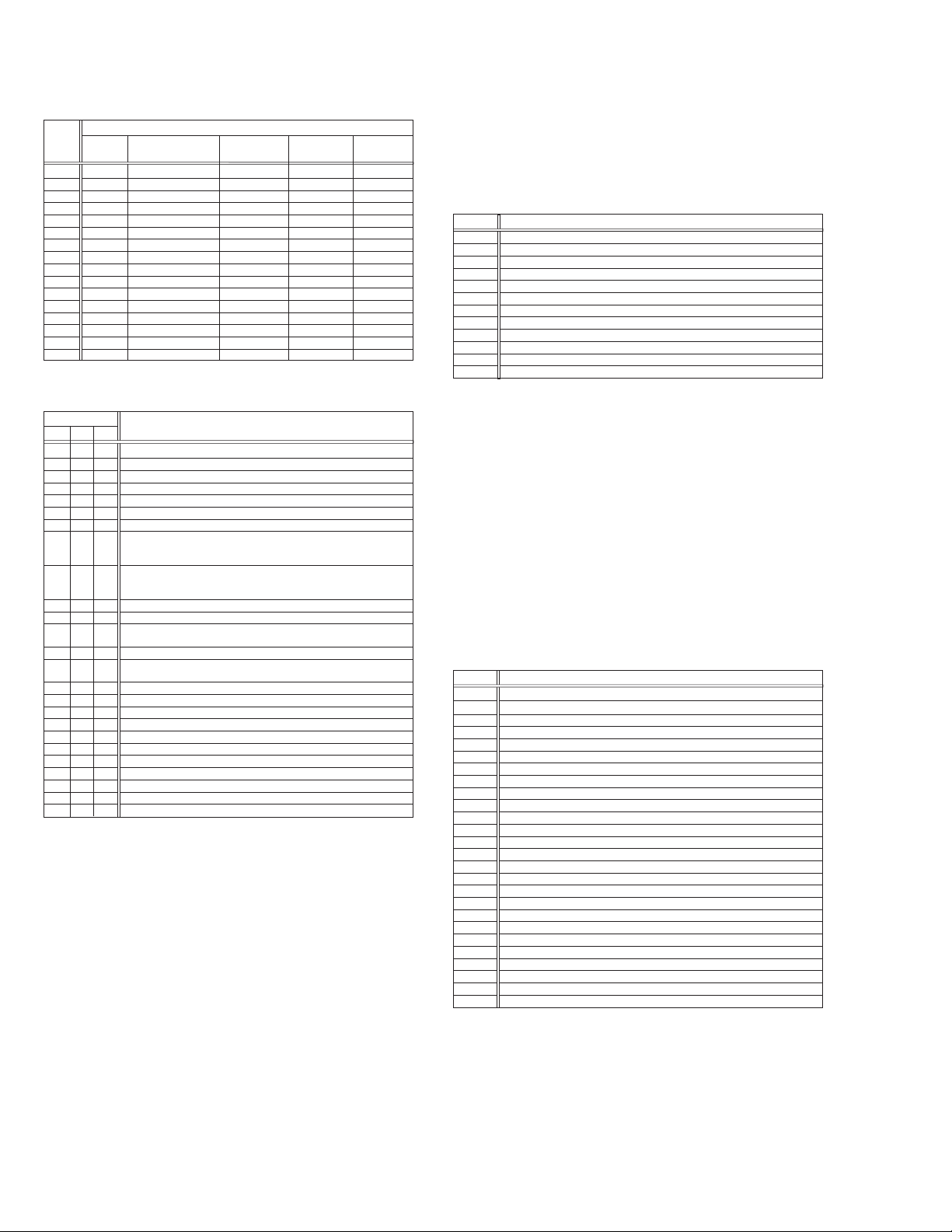
1.11.4 EMG detail information <1>
The status (electrical operation mode) of the VCR and the status (mechanism operation mode/sensor information) of the
mechanism in the latest EMG can be confirmed based on the
figure in EMG detail information <1> .
[FDP/OSD display]
*1 : *2 : 34
*1 : Deck operation mode at the moment of EMG
*2 : Mechanism operation mode at the moment of EMG
3– : Mechanism sensor information at the moment of EMG
–4 : Mechanism mode position at the moment of EMG
Note:
• For EMG detailed information <1>, the content of the code
that is shown on the FDP (or OSD) differs depending on
the parts number of the system control microprocessor
(IC3001) of the VCR. The system control microprocessor
parts number starts with two letters, refer these to the corresponding table.
*1 : Deck operation mode
[Common table of MN*, HD* and M3*]
Display
MN*/M3* HD*
00 - Mechanism being initialized
01 00 STOP with pinch roller pressure off (or tape present with P.OFF)
02 01 STOP with pinch roller pressure on
03 - POWER OFF as a result of EMG
04 04 PLAY
0C 0E REC
10 11 Cassette ejected
20 22 FF
21 - Tape fully loaded, START sensor ON, short FF
22 - Cassette identification FWD SEARCH before transition to FF (SP
24 26 FWD SEARCH (variable speed) including x2-speed
2C 2E INSERT REC
40 43 REW
42 - Cassette identification REV SEARCH before transition to REW (SP
44 47 REV SEARCH (variable speed)
4C 4C AUDIO DUB
6C 6E INSERT REC (VIDEO + AUDIO)
84 84 FWD STILL / SLOW
85 85 REV STILL / SLOW
8C 8F REC PAUSE
8D - Back spacing
8E - Forward spacing (FWD transport mode with BEST function)
AC AF INSERT REC PAUSE
AD - INSERT REC back spacing
CC CD AUDIO DUB PAUSE
CD - AUDIO DUB back spacing
EC EF INSERT REC (VIDEO + AUDIO) PAUSE
ED - INSERT REC (VIDEO + AUDIO) back spacing
x7-speed)
x7-speed)
Deck operation mode
*2 : Mechanism operation mode
[Common table of MN* and M3*]
Display
MN* M3*
00 00 Command standby (Status without executing command)
02 02 POWER OFF by EMG occurrence
04 04 Moving to the adjacent position in the LOAD direction
06 06 Moving to the adjacent position in the UNLOAD direction
08 08 Cassette ejection being executed / Cassette housing ejection being
- 0A Mode transition to STOP with cassette ejection end
0A 0C Cassette insertion being executed
0C 0E Tape being loaded
0E 10 Tape being unloaded
10 12 Mode transition to STOP with pinch roller compression ON
12 14 Mode transition to STOP with pinch roller compression OFF
14 16
16 18
18 1A Mode transition to PLAY
1A 1C Mode transition to FWD SEARCH
1C 1E Mode transition to REC
1E 20 Mode transition to FWD STILL / SLOW
20 22 Mode transition to REV STILL / SLOW
22 24 Mode transition to REV SEARCH
24 26 Mode transition from FF / REW to STOP
26 28 Mode transition to FF
28 2A Mode transition to REW
2A 2C 4 sec. of REV as a result of END sensor going ON during loading
2C 2E
2E 30 Mechanism position being corrected due to overrun
80 80 Mechanism in initial position (Dummy command)
executed
Mode transition to STOP with pinch roller compression OFF as a result
of POWER OFF
Mode transition to STOP with pinch roller compression ON as a result
of POWER ON
Short FF / REV as a result of END sensor going ON during unloading
Mechanism operation mode
[Table of HD*]
Display
00 STOP with pinch roller pressure off
01 STOP with pinch roller pressure on
02 U/L STOP (or tape being loaded)
04 PLAY
05 PLAY (x1-speed playback using JOG)
0E REC
11 Cassette ejected
22 FF
26 FWD SEARCH (variable speed) including x2-speed
2E INSERT REC
43 REW
47 REV SEARCH
4C AUDIO DUB
6E INSERT REC (VIDEO + AUDIO)
84 FWD STILL/SLOW
85 REV STILL/SLOW
8F REC PAUSE
AF INSERT REC PAUSE
C7 REV SEARCH (x1-speed reverse playback using JOG)
CD AUDIO DUB PAUSE
EF INSERT REC (VIDEO + AUDIO) PAUSE
F0 Mechanism being initialized
F1 POWER OFF as a result of EMG
F2 Cassette being inserted
F3 Cassette being ejected
F4 Transition from STOP with pinch roller pressure on to STOP with pinch
roller pressure off
F5 Transition from STOP with pinch roller pressure on to PLAY
F6 Transition from STOP with pinch roller pressure on to REC
F7 Cassette type detection SEARCH before FF/REW is being executed
F8 Tape being unloaded
F9 Transition from STOP with pinch roller pressure off to STOP with pinch
roller pressure on
FA Transition from STOP with pinch roller pressure off to FF/REW
FB Transition from STOP with pinch roller pressure off to REC.P (T.REC,etc.)
FC Transition from STOP with pinch roller pressure off to cassette type de-
tection SEARCH
FD Short REV being executed after END sensor on during unloading
FE Tension loosening being executed after tape loading (STOP with pinch
roller pressure on)
Mechanism operation mode
1-15
Page 22
3– : Mechanism sensor information
[Common table of MN*, HD* and M3*]
Display
MN* / HD* M3* REC safety Start End
S-VHS SW CASS SW SW sensor sensor
0- VHS Cassette insertion Tab broken ON ON
1- VHS Cassette insertion Tab broken ON OFF
2- VHS Cassette insertion Tab broken OFF ON
3- VHS Cassette insertion Tab broken OFF OFF
4- VHS Cassette insertion Tab present ON ON
5- VHS Cassette insertion Tab present ON OFF
6- VHS Cassette insertion Tab present OFF ON
7- VHS Cassette insertion Tab present OFF OFF
8- S-VHS Cassette ejection Tab broken ON ON
9- S-VHS Cassette ejection Tab broken ON OFF
A- S-VHS Cassette ejection Tab broken OFF ON
B- S-VHS Cassette ejection Tab broken OFF OFF
C- S-VHS Cassette ejection Tab present ON ON
D- S-VHS Cassette ejection Tab present ON OFF
E- S-VHS Cassette ejection Tab present OFF ON
F- S-VHS Cassette ejection Tab present OFF OFF
Mechanism sensor information
–4 : Mechanism mode position
[Common table of MN*, HD* and M3*]
Display Mechanism mode position
MN* HD* M3*
-0 -7 - Initial value
-1 -0 - EJECT position
- - -0 EJECT position (Cassette housing drive mode)
-2 -7 - Housing operating
- - -1 Between EJECT and U / L STOP
-3 -1 -2 U / L STOP position
- - -3 Guide arm drive position
-4 -7 -4 Tape being loaded / unloaded (When the pole base is
-5 -2 -5 Tape being loaded / unloaded (When the pole base is
-6 -7 -6 Pole base compressed position
-7 -3 -F FF / REW position
-8 -7 -F Between FF / REW and STOP with pinch roller compres-
-9 -4 -F STOP with pinch roller compression OFF
-A -7 -E Between STOP with pinch roller compression OFF and
-B -5 - REV (REV STILL / SLOW) position
- - -D REV position
- - -C Between REV and REV STILL / SLOW
- - -B REV STILL / SLOW position
-C -7 - Between REV and FWD
- - -A Between REV STILL / SLOW and FWD STILL / SLOW
-D -6 - FWD (FWD STILL / SLOW) position
- - -9 FWD STILL / SLOW position
-E -7 - Between FWD and PLAY
- - -8 Between FWD STILL / SLOW and PLAY
-F -6 -7 PLAY position
located on the front side of the position just beside the
drum)
located on the rear side of the position just beside the
drum)
sion ON
REV
Note:
• In the case of the "HD*” microprocessor, as the display is
always "-7” at any intermediate position between modes,
the position of transitory EMG may sometimes not be located.
1.11.5 EMG detail information <2>
The type of the cassette tape and the cassette tape winding position can be confirmed based on the figure in EMG detail information <2> .
[FDP/OSD display]
*5 : *6 : *7
*5 : Type of the cassette tape in use <1>
*6 : Winding position of the cassette tape in use
*7 : Type of th
e cassette tape in use
<2>
(Winding area)
Note:
• EMG detail information <2> is the reference information
stored using the remaining tape detection function of the
cassette tape. As a result, it may not identify cassette correctly when a special cassette tape is used or when the
tape has variable thickness.
*5 : Cassette tape type <1>
Display Cassette tape type <1>
00 Cassette type not identified
16
Large reel/small reel (T-0 to T-15/T-130 to T-210) not classified
82 Small reel, thick tape (T-120) identified/thin tape (T-140) identified
84 Large reel (T-0 to T-60) identified
92
Small reel, thick tape (T-130) identified/thin tape (T-160 to T-210) identified
93
Small reel, thick tape/C cassette (T-0 to T-100/C cassette) not classified
C3
Small reel, thick tape/C cassette (T-0 to T-100/C cassette) being classified
D3
Small reel, thick tape/C cassette (T-0 to T-100/C cassette) being classified
E1 C cassette, thick tape (TC-10 to TC-20) identified
E2 Small reel, thick tape (T-0 to T-100) identified
E9 C cassette, thin tape (TC-30 to TC-40) identified
C cassette, thick tape/thin tape (TC-10 to TC-40) not classified
F1
Notes:
Cassette tape type
•
<1>
is identified a few times during mode
transition and the identification count is variable depending on
the cassette tape type. If an EMG occurs in the middle of identification, the cassette tape type may not be able to be identified.
•
If other value than those listed in the above table is displayed,
the cassette tape type is not identified.
*6 : Cassette tape winding position
The cassette tape winding position at the moment of EMG is
displayed by dividing the entire tape (from the beginning to the
end) in 22 sections using a hex number from “00” to “15”.
“00” : End of winding
“15” : Beginning of winding
“FF or ––” : Tape position not identified
*7 : Cassette tape type <2> (Winding area)
Display Cassette tape type <2>
00 Cassette type not identified
07 Small reel, thick tape T-5
08 - 0E C cassette, thick tape TC-10
09 - 15 C cassette, thick tape TC-20P
0A - 0B Small reel, thick tape T-20
0A - 16 C cassette, thin tape TC-30
0A - 16 C cassette, thin tape TC-40
0D - 0F Small reel, thick tape T-40
11 - 14 Small reel, thick tape T-60
15 - 18 Small reel, thick tape T-80 / DF-160
17 - 1A Small reel, thick tape T-90 / DF-180
19 - 1D Small reel, thick tape T-100
1D - 21 Small reel, thick tape T-120 / DF-240
1E - 1F Small reel, thin tape T-140
1F - 23 Small reel, thick tape T-130
21 - 23 Small reel, thin tape T-160
21 - 23 Small reel, thin tape T-168
22 - 24 Small reel, thick tape DF-300
22 - 24 Small reel, thin tape T-180 / DF-360
22 - 24 Small reel, thin tape T-210 / DF-420
22 - 23 Large reel T-5
23 - 24 Large reel T-10
25 - 26 Large reel T-20
27 - 29 Large reel T-30
29 - 2B Large reel T-40
2D - 2F Large reel T-60
Note:
• The values of cassette tape type <2> in the above table
are typical values with representative cassette tapes.
1-16
Page 23

SECTION 2
MECHANISM ADJUSTMENT (VHS)
2.1 Before starting repair and adjustment
2.1.1 Precautions
(1) Unplug the power cord plug of the VCR before using your
soldering iron.
(2) Take care not to cause any damage to the conductor
wires when plugging and unplugging the connectors.
(3) Do not randomly handle the parts without identifying
where the trouble is.
(4) Exercise enough care not to damage the lugs, etc. dur-
ing the repair work.
(5) When reattaching the front panel assembly, make sure
that the door opener of the cassette holder assembly is
lowered in position prior to the reinstallation. (See SECTION 1 DISASSEMBLY.)
(6) When using the Jig RCU, it is required to set the VCR to
the Jig RCU mode (the mode in which codes from the
Jig RCU can be received). (See SECTION 1 DISASSEMBLY.)
Loading motor
2.1.2 Checking for proper mechanical operations
Enter the mechanism service mode when you want to operate the mechanism when no cassette is loaded. (See SECTION 1 DISASSEMBLY.)
2.1.3 Manually removing the cassette tape
1. In case of electrical failures
If you cannot remove the cassette tape which is loaded because of any electrical failure, manually remove it by taking
the following steps.
(1) Unplug the power cord plug from the power outlet.
(2) Refer to the disassembly procedure and perform the dis-
assembly of the major parts before removing the drum
assembly.
(3) Unload the pole base assembly by manually turning the
loading motor of the mechanism assembly toward the
front. In doing so, hold the tape by the hand to keep the
slack away from any grease. (See Fig.2-1-3a.)
(4) Bring the pole base assembly to a pause when it reaches
the position where it is hidden behind the cassette tape.
(5) Move the top guide toward the drum while holding down
the lug (A) of the bracket retaining the top guide. Likewise hold part (B) down and remove the top guide.
Section (C) of the top guide is then brought under the
cassette lid. Then remove the top guide by pressing the
whole cassette tape down. (See Fig.2-1-3b.)
(6) Remove the cassette tape by holding both the slackened
tape and the cassette lid.
(7) Take up the slack of the tape into the cassette. This com-
pletes removal of the cassette tape.
Note:
• For the disassembly procedure of the major parts and
details of the precautions to be taken, see “SECTION
1 DISASSEMBLY”.
Pole base assembly
Fig. 2-1-3a
(C)
(A)
(B)
Press
Fig. 2-1-3b
2-1
Page 24

2. In case of mechanical failure
If you cannot remove the cassette tape which is loaded because of any mechanical failure, manually remove it by taking the following steps.
(1) Unplug the power cable and remove the top cover, front
panel assembly and others so that the mechanism assembly is visible. (See SECTION 1 DISASSEMBLY.)
(2) While keeping the tension arm assembly of the mecha-
nism assembly free from tension, pull the tape on the pole
base assembly (supply or take-up side) out of the guide
roller. (See Fig.2-1-3c.)
(3) Take the spring of the pinch roller arm assembly off the
hook of the press lever assembly, and detach it from the
tape. (See Fig.2-1-3d.)
(4) In the same way as in the electrical failure instructions in
2.1.3-1(5), remove the top guide.
(5) Raise the cassette tape cover. By keeping it in that posi-
tion, draw out the cassette tape case from the cassette
holder and take out the tape.
(6) By hanging the pinch roller arm assembly spring back
on the hook, take up the slack of the tape into the cassette.
Pole base assembly (take-up side)
2.1.4 Jigs and tools required for adjustment
Roller driver
PTU94002
Back tension cassette gauge
PUJ48076-2
Alignment tape
(SP, stairstep, NTSC)
MHP
A/C head positioning tool
PTU94010
Jig RCU
PTU94023B
Alignment tape
(EP, stairstep, NTSC)
MHP-L
Torque gauge
PUJ48075-2
Pole base assembly
(supply side)
Tension arm assembly
Fig. 2-1-3c
Take the spring
off the hook, and
detach it from the
tape.
Guide pole guard
2-2
Pinch roller arm assembly
Press lever assembly
Fig. 2-1-3d
Page 25

2.1.5 Maintenance and inspection
1. Location of major mechanical parts
In this chapter, the two mechanism speeds are described by comparing the speeds of the standard type and the high-speed
FF/REW type.
It is possible to distinguish between these two types of mechanism by the diameters of their capstan pulleys.
The capstan pulley diameter for the standard type is approx. 32 mm.
The capstan pulley diameter for the high-speed FF/REW type is approx. 43 mm.
For information on the different parts used in the two mechanism types, please refer to the “Replacement of major parts”.
UV catcher2 (supply and take-up side)
Stator assembly
T2
Full erase head
T26
Pole base assembly
T25
(supply side)
Tension arm
T24
assembly
T23
Tension brake
T22
assembly
Adjust pin
T1
T5 T7
T3
Drum assembly
Head base
T6
A/C head
Loading motor
Guide pole guard
T8
Pinch roller arm
T9
assembly
Lid guide
T10
Press lever
T11
assembly
Guide arm
T12
assembly
Reel disk
T13
(take-up side)
Sub brake assembly
T14
(take-up side)
Belt
B22
(loading motor)
B21
Control cam
B20
B19
Cassette gear
B18
Worm gear
Brake lever
Rec safety lever
B1
Reel disk
T20
(supply side)
Main brake assembly
(supply side)
Idler lever
T17T19T21
Idler arm assembly
T16T18
Pole base assembly (take-up side)
Fig. 2-1-5a Mechanism assembly top side
Capstan motor
B2
Capstan brake assembly
B3 B5
Belt (capstan)
Loading arm gear (take-up side)
B4
Loading arm gear (supply side)
Main brake assembly
T15
(take-up side)
Plate
B6
(supply side)
Control
B7
bracket1
Control plate
B8
Tension arm
B9
bearing
Link lever
B17
Rotary encoder guide
B16
Rotary encoder
B15
B14
Direct gear
B13
Change lever assembly
B12
B10
Clutch unit
Take-up head
Fig. 2-1-5b Mechanism assembly bottom side
B11
Take-up lever
2-3
Page 26

Guide rail Roller cam assembly
L2L1
Fig. 2-1-5c Mechanism assembly left side
R1
Opener guide
Door
R2
opener
Drive gear
R3
Cassette housing bracket
R4
R5
Limit gear
Loading motor
Worm gear
Belt (loading motor)
Fig. 2-1-5d Mechanism assembly right side
2. Cleaning
Regular cleaning of the transport system parts is desirable
but practically impossible. So make it a rule to carry out cleaning of the tape transport system whenever the machine is
serviced.
When the video head, tape guide and/or brush get soiled,
the playback picture may appear inferior or at worst disappear, resulting in possible tape damage.
(1) When cleaning the upper drum (especially the video
head), soak a piece of closely woven cloth or Kimu-wipe
with alcohol and while holding the cloth onto the upper
drum by the fingers, turn the upper drum
counterclockwise.
Note:
• Absolutely avoid sweeping the upper drum vertically
as this will cause damage to the video head.
(2) To clean the parts of the tape transport system other than
the upper drum, use a piece of closely woven cloth or a
cotton swab soaked with alcohol.
(3) After cleaning, make sure that the cleaned parts are com-
pletely dry before using the video tape.
3. Lubrication
With no need for periodical lubrication, you have only to lubricate new parts after replacement. If any oil or grease on
contact parts is soiled, wipe it off and newly lubricate the
parts.
Note:
• See the “mechanism assembly” diagram of the parts
list for the lubricating or greasing spots, and for the
types of oil or grease to be used.
4. Suggested servicing schedule for main components
The following table indicates the suggested period for such
service measures as cleaning,lubrication and replacement.
In practice, the indicated periods will vary widely according
to environmental and usage conditions.However, the indicated components should be inspected when a set is brought
for service and the maintenance work performed if necessary. Also note that rubber parts may deform in time,even if
the set is not used.
System Parts Name
Upper drum assembly
A/C head
Lower drum assembly
Pinch roller arm assembly
Full erase head
Tension arm assembly
Capstan motor (Shaft)
Guide arm assembly
Capstan motor
Capstan brake assembly
Main brake assembly
Belt (Capstan)
Belt (Loading motor)
Loading motor
Clutch unit
Worm gear
Control plate
Brush
Tension brake assembly
Other Drive Tape transport
Rotary encoder
: Cleaning
¤
: Inspection or replacement if necessary
R
Operation Hours
~1000H ~2000H
¤R R
¤R ¤R
¤¤R
¤¤
¤¤
¤¤
¤¤
¤¤
R
R
R
RR
R
R
R
R
R
¤R ¤R
RR
R
Table 2-1-5a
5. Disassembling procedure table
The following table indicates the order in which parts are removed for replacement. To replace parts, remove them in
the order of 1 to 18 as shown in the table. To install them,
reverse the removal sequence.
The symbols and numbers preceding the individual part
names represent the numbers in the “Location of major mechanical parts” table. Also, the “T”, “B”, and “T/B” on the right
of each part name shows that the particular part is removed
from the front, from the back, and from both sides of the
mechanism, respectively.
2-4
Page 27

R4 R1 R3 T9 T12 T11 B15 B1 2 B14 B13 B17 B21 B7 B8 B5 B4 B11 T14 T15 T13 T22 T24 T18 B 19
Symbols and numbers
Removal parts
(Reference items)
Replacement parts
Symbols and numbers
2.2.3 Guide rail T 1
L2
2.2.3 Roller cam assembly T 1
R4
2.2.3 Cassette housing bracket T 1
R1
2.2.3 Opener guide T 2
R2
2.2.3 Door opener T 3
2.2.3 Relay gear T 3
R5
2.2.3 Limit gear T 3
2.2.3 Cassette holder assembly T 6
R3
2.2.3 Drive gear T 4
2.2.3 Drive arm T 8
T9
2.2.4 Pinch roller arm assembly T 1
T12
2.2.5 Guide arm assembly T 1
T11
2.2.5 Press lever assembly T 3
T6
2.2.6 A/C head T 1
T7
2.2.7 Loading motor T 1
B1
2.2.8 Capstan motor T/B 1
T1
2.2.9 UV catcher2 T 1
T17
Pole base assembly (take-up side)
2.2.9
T25
Pole base assembly (supply side)
2.2.9
B15
2.2.10 Rotary encoder B 1
B12
2.2.11 Clutch unit B 1
B14
2.2.12 Change lever assembly B 3
B13
2.2.12 Direct gear B 4
2.2.12 Coupling gear B 5
2.2.12 Clutch gear B 6
B17
2.2.13 Link lever B 1
2.2.14 Cassette gear B 2
B18
B20
2.2.14 Control cam B 2
B21
2.2.14 Worm gear B 1
T10
- Lid guide T/B 5
B7
2.2.15Control bracket1 B 1
2.2.15Control plate B 6
B8
B5
2.2.16Loading arm gear (supply side) B 7
B4
Loading arm gear (take-up side)
2.2.16
2.2.16Loading arm gear shaft B 9
2.2.17Take-up lever T/B 7
B11
B10
2.2.17Take-up head T/B 8
2.2.17Control plate guide T/B 8
B3
2.2.18Capstan brake assembly T/B 7
T14
Sub brake assembly(take-up side)
2.2.19
T15
Main brake assembly(take-up side)
2.2.20
T19
Main brake assembly(supply side)
2.2.20
T13
2.2.20Reel disk (take-up side) T/B 16
T22
2.2.21Tension brake assembly T/B 9
T20
2.2.21Reel disk (supply side) T/B 10
T24
2.2.21Tension arm assembly T/B 10
B9
2.2.21Tension arm bearing T/B 10
T18
2.2.22Idler lever T/B 17
T16
2.2.22Idler arm assembly T/B 18
B19
- Brake lever (
B16
- Rotary encoder guide T/B 19
1
) T/B 18
*
L1L1L2
Number of removal steps
Guide rail
Roller cam assembly
Cassette housing bracket
Opener guide
Front (T)/Back (B) of mechanism
1 2 3 4 5
12
T/B 2
T/B 2
B8
T/B 15
1 2 3 4
T/B 16
1 2 3 4 5 6 7 8
T/B 9
1 2 3 4 5 6 7 8
1 2 3 4 5 6 7 8
1 2 3 4 5 6 7 8
1 2 3 4 5 6 7 8
1 2 3 4 5 6 7 8
1 2 3 4 5 6 7 8
1 2 3 4 5 6 7 8
1 2 3 4 5 6 7 8
1 2 3 4 5 6 7 8
1 2 3 4 5 6 7 8
Relay gear
112
12
12
12 3
3
4 5
5 6
6 7
Cassette holder assembly
Drive gear
7
Table 2-1-5b
Note:
• The parts with marked (
nisms (standard type or high-speed FF/REW type).
1: Uses the standard type mechanism only.
*
2:Uses the high-speed FF/REW type mechanism only.
*
) have different types of mecha-
*
T1
Drive arm
Pinch roller arm assembly
Guide arm assembly
Press lever assembly
UV catcher2
Rotary encoder
Clutch unit
Change lever assembly
Direct gear
1
2
1
1
1
2
12
3
12
3
1 2 3 4 5
12
3 4
1 2 3 4
1 2 3 4 5
1 2 3 4 5 6
1 2 3 4 5 6 7
1 2 3 4 5 6
1 2 3 4 5 6
1 2 3 4 5 6
1 2 3 4 5 6
8
9 10 11 12 13 14
9 10 11 12 13 14 15
9 10 11 12 13 14 15
9 10 11 12 13 14 15 16
9 10 11 12 13 14 15 16 17
9 10 11 12 13 14 15 16 17
9 10 11 12 13 14 15 16 17 18
4
Coupling gear
Link lever
Worm gear
1
1
Control bracket1
Control plate
Loading arm gear (supply side)
Loading arm gear (take-up side)
Take-up lever
Sub brake assembly (take-up side)
Main brake assembly (take-up side)
Reel disk (take-up side)
Tension brake assembly
5
6
7
8
7
7
9
9
9
)
1
*
(
Tension arm assembly
Idler lever
Brake lever
2-5
Page 28

2.2 Replacement of major parts
2.2.1 Before starting disassembling (Phase matching
between mechanical parts)
The mechanism of this unit is closely linked with the rotary
encoder and system controller circuits.
Since the system controller detects the status of mechanical operation in response to phases of the rotary encoder
(internal switch positions), the mechanism may not operate
properly unless such parts as the rotary encoder, control
plate, loading arm gear, control cam, cassette gear, limit gear,
relay gear and drive gear are installed in their correct positions.
Especially, this model is not provided with any cassette housing assembly, so that cassette loading and unloading must
be accomplished by operation of the cassette holder assembly. The latter is in turn driven by such parts as the drive
gear, relay gear and limit gear. Exercise enough care, therefore, to have the phases of all this gear matching one another. (For information on phase matching of the mechanism,
see the instructions on how to install individual parts.)
This unit is provided with a mechanism assembly mode. It is
therefore necessary to enter this mode for assembling and
disassembling procedures.
This mode is usually not in use, manually set it when it is
required.
2.2.3 Cassette holder assembly
1. How to remove
(1) Remove the guide rail and roller cam assembly. (See
Fig.2-2-3a.)
(3 lugs on the guide rail and one lug on the roller cam
assembly)
Guide rail
Lugs
Roller cam
assembly
Lug
Lug
Fig. 2-2-3a
(2) Remove the two slit washers and remove the cassette
housing bracket. (See Fig.2-2-3b.)
(3) Remove the opener guide, spring(A), door opener, relay
gear and limit gear. (See Fig.2-2-3b.)
2.2.2 How to set the “Mechanism assembling mode”
Remove the mechanism assembly and place it bottom side
up. (See SECTION 1 DISASSEMBLY.) Turn the worm gear
toward the front so that the guide hole of the control cam is
brought into alignment with the hole at the mechanism assembly chassis. This position renders the mechanism assembling mode operational. Make sure that the control plate is
located in alignment with the mark E. (See Fig.2-2-2a.)
Worm gear
Chassis hole
Guide hole
Control cam
Limit gear
Spring(A)
Opener guide
Relay gear
Door opener
Cassette housing bracket
Slit washers
Fig. 2-2-3b
(4) While swinging the lock levers (R) and (L) of the cassette
holder assembly toward the front, slide the cassette
holder assembly until its legs come to where the guide
rail and the roller cam assembly have been removed (so
that the drive arm is upright). (See Fig.2-2-3c.)
Lock lever (L)
Cassette holder assembly
Drive arm
(Upright)
2-6
Control plate
Fig. 2-2-2a
Mark E
Leg Legs
Fig. 2-2-3c
Page 29

While holding the left side of the cassette holder, lift the
(5)
cassette holder assembly so that the three legs on the
left side are all released. Then pull the legs (A) and (B)
on the right side out of the rail and also pull up the leg(C).
(See Fig.2-2-3d and Fig.2-2-3e.)
(6) Draw out the drive gear, and remove the drive arm.
Cassette holder assembly
Fig. 2-2-3d
Cassette holder assembly
(A)
2. How to install (Phase matching)
(1) Insert the section (A) of the drive arm into the section (B)
of the main deck.
(2) Insert the section (1) of the drive gear into the round hole,
and the section (2) into the square hole on the drive arm.
(See Fig.2-2-3f.)
(3) Hold the drive arm upright and fit the leg (C) on the right
side of the cassette holder assembly into the groove. (See
Fig.2-2-3g.)
(4) While swinging the lock lever (R) of the cassette holder
assembly toward the front, put the legs (A) and (B) into
the rail. (See Fig.2-2-3g.)
(5) Drop the three legs on the left side of the cassette holder
assembly into the groove at one time. (See Fig.2-2-3h.)
(6) Slide the whole cassette holder assembly toward the front
to bring it to the eject end position.
(7) Install the limit gear so that the notch on the outer cir-
cumference of the limit gear is brought into alignment with
the guide hole on the main deck. (See Fig.2-2-3i.)
(8) Install so that the notch on the periphery of the relay gear
is aligned with the notch of the main deck and that hole
A of the relay gear is aligned with the hole A of the limit
gear and that hole B of the relay gear is aligned with the
hole B of the drive gear. (See Fig.2-2-3i.)
(9) Install the door opener, opener guide, spring(A) and cas-
sette housing bracket and fasten the two slit washers.
Cassette holder assembly
Fig. 2-2-3e
Main deck right side
Drive arm
Hole
(C)
Lock lever (R)
(A)
(B)
(B)
Drive arm
Drive arm
(C)
Fig. 2-2-3g
Cassette holder assembly
Hole
Drive gear
(1)
(2)
(A)
Fig. 2-2-3f
(B)
Fig. 2-2-3h
2-7
Page 30

Relay gear
B
Guide holeNotches Notch
2.2.6 A/C head
1. How to remove
(1) Remove the two screws (A) and remove the A/C head
together with the head base.
(2) When replacing only the A/C head, remove the three
screws (B) while controlling the compression spring.
Head base
B
AA
Drive gear Limit gear
Fig. 2-2-3i
2.2.4 Pinch roller arm assembly
1. How to remove
(1) Remove the spring from the hook of the press lever as-
sembly.
(2) Remove the slit washer and remove the pinch roller seat
2. (See Fig.2-2-4a.)
(3) Remove the pinch roller arm assembly by pulling it up.
Slit washer
Pinch roller seat2
Spring
Pinch roller arm
Press lever assembly
Pinch roller arm assembly
assembly
Fig. 2-2-4a
2.2.5 Guide arm assembly and press lever assembly
1. How to remove
(1) Remove the spring and expand the lug of the lid guide in
the arrow-indicated direction. Then remove the guide arm
assembly by pulling it up.
(2) Remove the press lever assembly by pulling it up. (See
Fig.2-2-5a.)
Screws(A)
A/C head
Fig. 2-2-6a
Screws(B)
A/C head
Compression
A/C head board
assembly
Head base
springs
Fig. 2-2-6b
2. How to install
(1) To make the post-installation adjustment easier, set the
temporary level as indicated in Fig.2-2-6c. Also make sure
that the screw center (centre) is brought into alignment
with the center (centre) position of the slot.
A/C head
12.4 mm
Head base
Screw
2-8
Tension
spring
LugLid guide
Fig. 2-2-5a
Press lever
assembly
Guide arm
assembly
Head base
A/C head
Fig. 2-2-6c
2.2.7 Loading motor
1. How to remove
(1) Remove the belt wound around the worm gear.
(2) Open the two lugs of the motor guide and remove the
loading motor, loading motor board assembly and motor
guide altogether by pulling them up.
(3) When replacing the loading motor board assembly, take
care with the orientation of the loading motor. (Install so
that the loading motor label faces upward.)
(4) When the motor pulley has been replaced, choose the
fitting dimension as indicated in Fig.2-2-7a.
Page 31

Loading motor board assembly
Loading motor
Lugs
Motor guide
6.5 ± 0.2 mm
LABEL
Motor pulley
Worm gear
Belt
Fig. 2-2-7a
2.2.8 Capstan motor
1. How to remove
(1) Remove the belt (capstan) on the mechanism assembly
back side.
(2) Remove the three screws (A) and remove the capstan
motor.
Screws(A)
Screw(A)
Capstan motor
Belt
Fig. 2-2-8a
Spacer
Spacer
2. How to install (Centering the mounting position)
When the capstan motor has once been removed and then
reinstalled out of the initial correct position in the rotational
direction, the capstan motor current may be unstable during
operation in high or low temperatures. This may result in
greater Wow & Flutter and occasionally in power breakdown
because of current over - load. Install the capstan motor while
following the procedure given below.
(The capstan motor is centrally located when the unit is
shipped from the factory.)
(1) Provisionally tighten the three screws (A) securing the
capstan motor.
(2) Install the mechanism assembly to which the capstan
motor is provisionally fastened on the bottom chassis
which incorporates the Main board assembly. (No need
to tighten the screws for mounting the mechanism.)
Make sure that all the connectors for the mechanism assembly and the Main board assembly are correctly installed as indicated in Fig. 2-2-8b.
(3) Making sure that the connector for the capstan motor is
correctly mounted, and securely tighten the three screws
(A).
Note:
• When the capstan motor has been replaced with a new
one, perform recording in the EP(or LP) mode for at
least 2 minutes at normal temperatures immediately before starting the FF/REW or SEARCH operations (Aging).
2.2.9 Pole base assembly (supply or take-up side)
1. How to remove
(1) Remove the UV catcher 2 on the removal side by loos-
ening the screw (A).
(2) Remove the pole base assembly on the supply side from
the mechanism assembly by loosening the screw (B) on
the mechanism assembly back side and sliding the pole
base assembly toward the UV catcher 2.
(3) As for the pole base assembly on the take-up side, turn
the pulley of the loading motor to lower the cassette
holder because the screw (B) is hidden under the control plate. (See the “Procedures for Lowering the Cassette
holder assembly” of 1.3 DISASSEMBLY/ASSEMBLY
METHOD.) Further turn the motor pulley to move the cassette holder until the screw (B) is no longer under the control plate (in the half-loading position). Then remove it as
done for the supply side by removing the screw (B).
Note:
• After reinstalling the Pole base assembly and the UV
catcher2, be sure to perform compatibility adjustment.
Fig. 2-2-8b
Connector for
the capstan motor
Screw(A)
UV catcher2
Screw(A)
UV catcher2
Screw(B)
Fig. 2-2-9a
2-9
Page 32

2.2.10 Rotary encoder
1. How to remove
(1) Remove the screw (A) and remove the rotary encoder
by pulling it up. (See Fig. 2-2-10a.)
Rotary encoder (Front side)
Screw(A)
Guide marks
2.2.12 Change lever assembly, direct gear, clutch gear
and coupling gear
1. How to remove
(1) Release the two lugs of the rotary encoder guide in the
arrow-indicated direction and remove the change lever
assembly.
(2) Remove the slit washer retaining the direct gear and re-
move the latter.
Take care so as not to lose the washer and spring. (See
Fig.2-2-12a.)
Rotary encoder (Back side)
Positioning pin of the rotary encoder
Fig. 2-2-10a
Mark E
Shaft of the rotary encoder guide
Control plate
Fig. 2-2-10b
2. How to install (Phase matching)
(1) Make sure that the mark E of the control plate is in align-
ment with the mark
of the loading arm gear shaft and
bring the guide marks on the rotary encoder into alignment as indicated in Fig.2-2-10a. (See Fig. 2-2-10a and
Fig. 2-2-10b.)
(2) Turn over the rotary encoder with its guide marks kept in
alignment and install it by fitting on the shaft of the rotary
encoder guide and the positioning pin.
(3) Tighten the screw (A) to complete the installation.
2.2.11 Clutch unit
(1) Remove the belt wound around the capstan motor and
the clutch unit.
(2) Remove the slit washer and remove the clutch unit.
Change lever
assembly
Spring(B)
Lugs
Note:
• The parts with marked (
speed FF/REW type).
1 : Uses the standard type mechanism only.
*
2:
Uses the high-speed FF/REW type mechanism only.
*
Slit washer
Washer (*1)
Spacer
Direct gear
Spring(A)
Position the projecting
side down.
) have different types of mechanisms (standard type or high-
*
Coupling gear
Spring (C)
Clutch gear
Spacer
Fig. 2-2-12a
2. How to install
(1) Install the clutch gear, spring (A), spring (C), direct gear,
spacer and others to the individual shafts of the main
deck, and finally the slit washer. (See Fig.2-2-12a.)
(2) Let the spring (B) drops into the rotary encoder guide hole
and install the change lever assembly.(Take care not to
mistake a direction of the spring.) The point is to slightly
lift the coupling gear and catch it from the both sides with
the assembly. (See Fig.2-2-12b.)
Rotary encoder guide
Spring(B)
Change lever assembly
Coupling gear
2-10
Belt
Clutch unit
Fig. 2-2-11a
Slit washer
Main deck Main deck
Fig. 2-2-12b
Page 33

2.2.13 Link lever
1. How to remove
(1) Remove the two slit washers.
(2) Remove the link lever by lifting it from the shaft retained
by the slit washers. Then swing the link lever
counterclockwise and remove it from the locking section
of the control plate.
Slit washers
2.2.14 Cassette gear, control cam and worm gear
1. How to remove
(1) Remove the control cam by lifting it.
(2) Open the two lugs of the cassette gear outward and pull
the latter off.
(3) Remove the belt wound around the worm gear and the
loading motor.
(4) Open the lug of the lid guide outward and remove the
worm gear.
Link lever
Locking section of the
control plate
Fig. 2-2-13a
2. How to install (Phase matching)
(1) Slide the control plate so that its mark E is aligned with
the mark
on the loading arm gear shaft. (See Fig.2-2-
13b.)
(2) Rotate the worm gear until the guide hole of the control
cam is aligned exactly with the guide hole of the main
deck. (See Fig.2-2-13c.)
(3) Insert the link lever into the locking section of the control
plate. (See Fig.2-2-13a.)
(4) Rotate the link lever clockwise so that it is installed on
the shafts in the center (centre) and on the left of the control cam.
(5) Fasten the slit washers at these two points.
Loading motor
Belt
Lug
Worm gear
Lugs
Cassette gear
Lid guide
Control cam
Fig. 2-2-14a
2.2.15 Control plate
1. How to remove
(1) Remove the screw (A) retaining the control bracket 1 and
remove the latter.
(2) Slide the control plate as indicated by the arrow and re-
move the control plate. (See Fig.2-2-15a.)
Shaft of the rotary encoder guide
Fig. 2-2-13b
Worm gear
Main deck
guide hole
Control cam
guide hole
Cassette gear
Fig. 2-2-13c
Control plate
Control cam
Mark E
Screw(A)
Control
bracket1
Control
plate
Fig. 2-2-15a
2. How to install (Phase matching)
(1) Adjust the position of the idler arm assembly pin as indi-
cated in Fig.2-2-15b (to the left of center (centre) of the
R section).
(2) Bring the guide hole of the take-up lever into alignment
with the hole at the control plate guide and fix the position by inserting a 1.5 mm hexagonal wrench.
2-11
Page 34

(3) Install the control plate so that the section A of the load-
ing arm gear shaft fits into the hole (A) of the control plate,
the section B of the control plate guide into the hole (B),
and the control plate comes under the section C of the
rotary encoder guide and the section D of the loading arm
gear shaft while press-fit the pole base assmebly (supply side) as indicated by the arrow. It is important that
the tension arm assembly shaft is positioned closer toward you than the control plate. (See Fig.2-2-15c.)
(4) Make sure that the mark E of the control plate is in align-
ment with the mark
of the loading arm gear shaft. (See
Fig.2-2-15c.)
(5) Pull off the hexagonal wrench for positioning.
(3) Turn the loading arm gear (take-up side) clockwise so
that the notch of the loading arm gear (take-up side) is
in alignment with the projection of the loading arm gear
shaft and lift it.
Likewise, turn the loading arm counterclockwise so that
the notch is in alignment with the projection and remove
the loading arm gear (take-up side). (See Fig.2-2-16a and
Fig. 2-2-16b.)
(4) When removing the loading arm gear shaft, be sure of
first removing the screw retaining the drum assembly (on
the back side of the loading arm gear shaft). Then remove the screw (C) and remove the loading arm gear
shaft by sliding it.
Idler arm assembly
pin
R section
Guide hole of the
control plate guide
Section D
1.5mm hexagonal wrench
Fig. 2-2-15b
Section A
Section D
Hole A
Pressfit
Take-up lever
Insert
Pole base assembly
(supply side)
Section A
Hole A
Pole base assembly
(take-up side)
Screw(B)
Torsion arm
Loading arm gear
(take-up side)
Projection B
Guide marks
Projection A
Pole base assembly
(supply side)
Screw(A)
Loading arm gear
(supply side)
Fig. 2-2-16a
Loading arm gear shaft
Loading arm gear (take-up side)
Notch
Screw(C)
Loading arm gear shaft
Section C
Section C
Section B
Hole B
Hole B
Section B
Control plate
Tension arm assembly
shaft
Fig. 2-2-15c
2.2.16 Loading arm gear (supply or take-up side) and
loading arm gear shaft
1. How to remove
(1) Remove the loading arm gear (supply side) by loosen-
ing the screw (A). (See Fig. 2-2-16a.)
(2) Remove the screw (B) and remove the torsion arm from
the pole base assembly (take-up side). (See Fig.2-2-16a.)
2-12
Fig. 2-2-16b
2. How to install
(1) Align the notch of the loading arm gear (take-up side) to
the projection B of the loading arm gear shaft and slip it
over. Then rotate it clockwise for alignment with the projection A and slip it down to the bottom. (See Fig.2-216b.)
(2) Then turn the loading arm gear (take-up side)
counterclockwise. Hang the torsion arm on the pole base
assembly (take-up side) and tighten the screw (B).
(3) Install the loading arm gear (supply side) so that the guide
mark of the loading arm gear (take-up side) is in alignment with the guide mark of the loading arm gear (supply side). Then hang the torsion arm on the pole base
assembly (supply side) and tighten the screw (A). (See
Fig.2-2-16a.)
Page 35

2.2.17 Take-up lever, take-up head and control plate
guide
(1) Remove the spring of the take-up lever from the main
deck.
(2) Remove the lug (A) of the take-up lever from the main
deck and pull out the take-up lever and the take-up head
together.
(3) Remove the screw (A).
(4) Align the idler arm assembly pin in the center (centre) of
the R section of the control plate guide, remove the con-
trol plate guide lugs (B) and (C) from the main deck, and
remove the control plate guide.
Idler arm assembly pin
Lug(C)
Screw(A)
Take-up lever
Take-up head
Lug(A)
Lug(B)
Control plate guide
Fig. 2-2-17a
2.2.18 Capstan brake assembly
1. How to remove
(1) Move the lug (A) of the capstan brake assembly in the
arrow-indicated direction so that it comes into alignment
with the notch of the main deck. (See Fig. 2-2-18a.)
(2) Remove the lug (B) of the capstan brake assembly from
the main deck and remove the capstan brake assembly.
Spring
Sub brake
Lug(A)
Lug(B)
assembly
(take-up side)
Lug(C)
Fig. 2-2-19a
2.2.20 Main brake assembly (take-up side), reel disk
(take-up side) and main brake assembly (supply
side)
1. How to remove
(1) Move the main brake assembly (take-up side) in the ar-
row-indicated direction and remove the reel disk (takeup side).
Remove the spring attached to the main brake assembly.
(2)
(3) Remove the lug (A) of the main brake assembly (take-
up side) and pull out the lug (B) after bringing it into alignment with the main deck notch.
(4) Remove the lugs (C), (D) and (E) of the main brake as-
sembly (supply side) from the main deck and pull them
off. (See Fig.2-2-20a.)
(5) When installing the main brake assembly (take-up side),
slide the brake lever in the direction as indicated by the
arrow to prevent it from hitting the projection of the main
brake assembly (take-up side). (See Fig.2-2-20b.)
Main brake assembly
(supply side)
Reel disk
(take-up side)
Main brake assembly
(take-up side)
Lug(B)
Lug(A)
Capstan brake assembly
Fig. 2-2-18a
2.2.19 Sub brake assembly (take-up side)
1. How to remove
(1) Remove the spring attached to the lid guide and sub
brake assembly (take-up side).
(2) Bring the lug (A) of the sub brake assembly (take-up side)
into alignment with the notch of the main deck.
(3) Remove the lugs (B) and (C) of the sub brake assembly
(take-up side) from the main deck and remove the sub
brake assembly (take-up side).
Lug(B)
Lug(C)
Lug(D)
SpringLug(E)
Lug(A)
Notch
Fig. 2-2-20a
1)
(
*
Brake
lever
Note:
• The parts with marked ( *) have different types of mechanisms (standard type
or high-speed FF/REW type).
1 : Uses the standard type mechanism only.
*
Rotary encoder guide
Projection of the main
brake assembly
(take-up side)
Fig. 2-2-20b
2-13
Page 36

2.2.21 Tension brake assembly, reel disk (supply side)
and tension arm assembly
1. How to remove
(1) Remove the three lugs of the tension brake assembly
from the main deck and pull them off.
(2) Remove the reel disk (supply side) by loosening in the
arrow-indicated direction the main brake assembly (supply side).
(3) Remove the tension spring on the back of the main deck.
Then release the lug of the tension arm bearing in the
arrow-indicated direction and draw out the tension arm
assembly. (See Fig. 2-2-21a.)
Lug of the tension
arm bearing
Tension arm
assembly
Reel disk
(supply side)
2.2.23 Stator assembly
(1) Remove the flat cable.
(2) Remove the two screws (A), (B) and remove the lug wire.
(3) Remove the stator assembly by lifting in the arrow-indi-
cated direction. (Take care that the brush spring does not
jump out.)
Notes:
• Be careful not to lose the brush and spring.
• There are some models that do not use the lug wire.
Refer to the parts list for these models.
• When tightening the screw (B), place the caulked part
of the lug terminal near to the shaft of the drum and
then tighten it.
• After installation, be sure to perform the switching
point adjustment according to the electrical adjustment
procedure.
Tension brake
assembly
Lugs
Tension spring Main brake assembly
(supply side)
Fig. 2-2-21a
2.2.22 Idler lever, idler arm assembly
1. How to remove
(1) Remove the lug of the idler lever from the main deck and
remove the hook fitted in the idler arm assembly hole by
lifting it.
(2) Remove the slit washer and pull out the idler arm assem-
bly.
Lug Idler lever
Hook
Idler arm
assembly
Slit washer
Screw (A)
Stator assembly
Screw (B)
Lug wire
(Note)
Drum
shaft
Flat cable
(Take care not to mix up the
polar faces when installing.)
Lug wire
Screw (A)
Fig. 2-2-23a
2.2.24 Rotor assembly
1. How to remove
(1) Remove the stator assembly.
(2) Remove the two screws (B) and remove the rotor assem-
bly.
2. How to install
(1) Match the phases of the upper drum assembly and the
rotor assembly as indicated in Fig.2-2-24a.
(2) Place the upper drum assembly hole (a) over the rotor
assembly holes (b) (with three holes to be aligned) and
tighten the two screws (B). (See Fig.2-2-24a.)
Screws (B)
Hole(a)
2-14
Fig. 2-2-22a
Screw holes
Upper drum
assembly
Rotor assembly
Fig. 2-2-24a
The hole is not in
line but is offset
toward the right.
Hole(b)
Page 37

2.2.25 Upper drum assembly
Notes:
• To replace the upper drum assembly only may not be
possible with some models. For upper drum assembly replacement, refer to the parts list. (When the parts
number of the upper drum assembly is not listed on
the parts list, then this cannot be replaced.)
• When replacement is required, control the up- down
movement of the brush. Never apply grease.
• When replacing the upper drum assembly, replace it
the together with the washer.
1. How to remove
(1) Remove the stator assembly and rotor assembly.
(2) Loosen the screw of the collar assembly using a 1.5 mm
hexagonal wrench and remove the collar assembly. Also
remove the brush, spring and cap at one time.
(3) Remove the upper drum assembly and remove the
washer using tweezers.
Lower drum assembly
Coil parts
Upper drum assembly
Fig. 2-2-25b
Spring
Brush
Upper drum
assembly
Washer
Collar
assembly
Loosen
Cap
Shaft
1.5 mm
hexagonal wrench
Lower drum assembly
Fig. 2-2-25a
2. How to install
(1) Clean the coil parts of the lower drum assembly and the
newly installed upper drum assembly with an air brush
in advance. (See Fig.2-2-25b.)
(2) Install a new washer and upper drum assembly on the
drum shaft. (See Fig.2-2-25a.)
(3) Install the cap to the upper drum assembly.
(4) Position the collar assembly as indicated in Fig.2-2-25c
while controlling its up- down movement.
(5) Secure the collar assembly in position with a hexagonal
wrench while pressing its top with the fingers.
(6) After installation, gently turn the upper drum assembly
with your hand to make sure that it turns normally. Then
install the brush and the spring.
(7) Install the rotor assembly and stator assembly according
to Fig 2-2-23a and 2-2-24a.
(8) When installation is complete, clean the upper drum as-
sembly and lower drum assembly and carry out the fol-
lowing adjustments.
• PB switching point adjustment
• Slow tracking adjustment
• Compatibility adjustment (Be sure to check for compatibility for the EP (or LP) mode.)
Upper drum
assembly
Collar
assembly
Fig. 2-2-25c
Press
Fig. 2-2-25d
Collar
assembly
Tighten
2-15
Page 38

2.3 Compatibility adjustment Notes:
• Although compatibility adjustment is very important,
it is not necessary to perform this as part of the normal servicing work. It will be required when you have
replaced the A/C head, drum assembly or any part of
the tape transport system.
• To avoid any damage to the alignment tape while performing the compatibility adjustment, get a separate
cassette tape (for recording and play back) ready to
be used for checking the initial tape running behavior.
• Unless otherwise specified, all measuring points and
adjustment parts are located on the Main board.
• When using the Jig RCU, it is required to set the VCR
to the Jig RCU mode (the mode in which codes from
the Jig RCU can be received). (See SECTION 1 DISASSEMBLY.)
Jig RCU
[Data transmitting method]
Depress the “ ” ( 3 ) button
after the data code is set.
pole base assembly (supply or take-up side).
(7) Unload the cassette tape once, play back the alignment
tape (A1) again and confirm the V.PB FM waveform.
(8) After adjustment, confirm that the tape wrinkling does not
occur at the roller upper or lower limits. (See Fig. 2-31d.)
[Perform adjustment step (9) only for the models
equipped with SP mode and EP (or LP) mode.]
(9) Repeat steps (1) to (8) by using the alignment tape (A2).
CUSTOM CODE
43: A CODE
DATA CODE
INITIAL MODE
Fig. 2-3a Jig RCU [PTU94023B]
2.3.1 FM waveform linearity
Signal (A1) •
(A2) •
Mode (B) • PB
Equipment (C) •Oscilloscope
Measuring point (D) •TP106 (PB. FM)
External trigger (E) • TP111 (D.FF)
Adjustment part (F) • Guide roller [Mechanism assembly]
Specified value (G) • Flat V.PB FM waveform
Adjustment tool (H)
Alignment tape(SP, stairstep, NTSC) [MHP]
Alignment tape(EP, stairstep, NTSC) [MHP-L]
• Roller driver [PTU94002]
(1) Play back the alignment tape (A1).
(2) Apply the external trigger signal to D.FF (E), to observe
the V.PB FM waveform at the measuring point (D).
(3) Set the VCR to the manual tracking mode.
(4) Make sure that there is no significant level drop of the
V.PB FM waveform caused by the tracking operation, with
its generally parallel and linear variation ensured. Per-
form the following adjustments when required. (See Fig.
2-3-1a.)
(5) Reduce the V.PB FM waveform by the tracking opera-
tion. If a drop in level is found on the left side, turn the
guide roller of the pole base assembly (supply side) with
the roller driver to make the V.PB FM waveform linear.
If a drop in level is on the right side, likewise turn the guide
roller of the pole base assembly (take-up side) with the
roller driver to make it linear. (See Fig. 2-3-1c.)
(6) Make sure that the V.PB FM waveform varies in parallel
and linearly with the tracking operation again. When re-
quired, perform fine-adjustment of the guide roller of the
Max level
Proper waveform variation
Improper waveform variation
Fig. 2-3-1a
Roller driver
Fig. 2-3-1b
Min level
Guide roller (supply side)
2-16
Page 39

A
B
waveform by turning the screws (1), (2) and (3) little by
little until both waveforms reach maximum. The screw (1)
and (3) are for adjustment of tilt and the screw (2) for azimuth.
(4) Adjust the AUDIO OUT waveform and Control pulse
Level drop at the guide roller (supply side)
C
Level drop at the guide roller (take-up side)
• Proper waveform variation: Always flat
• Improper waveform variation:
Higher Lower
Fig. 2-3-1c
Improper
(a) Guide roller
Head base
A/C head
(2)
(3)
(1)
AUDIO OUT
CTL. P
D
Fig. 2-3-2a
2.3.3 A/C head phase (X-value)
Proper
Signal (A1) •
Mode (B) • PB
Equipment (C) •Oscilloscope
Measuring point (D) • TP106 (PB. FM)
External trigger (E) • TP111 (D.FF)
Adjustment part (F) •
Specified value (G) • Maximum V.PB FM waveform
Adjustment tool (H) • A/C head positioning tool [PTU94010]
Alignment tape(SP, stairstep, NTSC) [MHP]
A/C head base [Mechanism assembly]
(b) Guide pole
Fig. 2-3-1d
2.3.2 Height and tilt of the A/C head
Note:
• Set a temporary level of the height of the A/C head in
advance to make the adjustment easier after the A/C
head has been replaced. (See Fig.2-2-6c.)
Signal (A) •
Mode (B) • PB
Equipment (C) •Oscilloscope
Measuring point (D1)
(D2) • TP4001 (CTL. P)
External trigger (E) • TP111 (D.FF)
Adjustment part (F) • A/C head [Mechanism assembly]
Specified value (G) • Maximum waveform
Alignment tape(SP, stairstep, NTSC) [MHP]
• AUDIO OUT terminal
(1) Play back the alignment tape (A).
(2) Apply the external trigger signal to D.FF (E), to observe
the AUDIO OUT waveform and Control pulse waveform
at the measuring points (D1) and (D2) in the ALT mode.
(3) Set the VCR to the manual tracking mode.
(1) Play back the alignment tape (A1).
(2) Apply the external trigger signal to D.FF (E), to observe
the V.PB FM waveform at the measuring point (D).
(3) Set the VCR to the manual tracking mode.
(4) Loosen the screws (4) and (5), then set the A/C head
positioning tool to the innermost projected part of the A/
C head. (See Fig. 2-3-3a.)
(5) Turn the A/C head positioning tool fully toward the cap-
stan. Then turn it back gradually toward the drum and
stop on the second peak point position of the V.PB FM
waveform output level. Then tighten the screws (4) and
(5).
(6) Perform the tracking operation and make sure that the
V.PB FM waveform is at its maximum.
If it is not at maximum, loosen the screws (4) and (5),
and turn the A/C head positioning tool to bring the A/C
head to a position, around where the waveform reaches
its maximum for the first time. Then tighten the screws
(4) and (5).
2-17
Page 40

[Perform adjustment steps (7) to (10) only for 2 Head
models equipped with LP mode.]
(7) Then play back the alignment tape (A2).
(8) Set the VCR to the manual tracking mode.
(9) Perform the tracking operation and make sure that the
V.PB FM waveform is at its maximum.
(10)
If it is not at maximum, loosen the screws (4) and (5),
and turn the A/C head positioning tool to bring the A/C
head to a position, around where the waveform reaches
its maximum for the first time. Then tighten the screws
(4) and (5).
Note:
• After adjusting, always perform the confirmation and
re-adjustment of the item 2.3.4.
Toward the drum
A/C head positioning tool
To the drum
A/C head
Toward the capstan
Head base
Screw
Screw
To the capstan
(4)
(5)
Fig. 2-3-3a
Alignment tape
[SP, stairstep]
played with the
SP head
Alignment tape
[EP(LP), stairstep]
played with the
EP(LP) head
(4) Set the VCR to the Auto adjust mode by transmitting the
code (F) twice from the Jig RCU. When the VCR enters
the stop mode, the adjustment is completed.
(5) If the VCR enters the eject mode, perform adjustment for
the audio control head phase (X-value) again.
2.3.5 Tension pole position
Signal (A) • Back tension cassette gauge
Mode (B) • PB
Adjustment part (F) • Adjust pin [Mechansim assembly]
Specified value (G)
[PUJ48076-2]
• 25 - 51 gf•cm (2.45 – 5 × 10
-3
Nm]
(1) Play back the back tension cassette gauge (A).
(2) Check that the indicated value on the left side gauge is
within the specified value (G).
(3) If the indicated value is not within the specified value (G),
perform the adjustment in a following procedure.
1) Set the VCR to the mechanism service mode. (See
SECTION 1 DISASSEMBLY.)
2) Set the VCR to the play back mode and adjust by turning adjustment pin to align the tension arm assembly
edge with the main deck hole (A) on the right edge
marker. (See Fig. 2-3-5a)
Tension arm
assembly
Hole (A)
Marker
Edge
Waveform output
X-value adjustment point
Drum side Control head position Capstan side
Maximum
Fig. 2-3-3b
2.3.4 Standard tracking preset
Signal (A) •
Mode (B) • PB ¥ Auto adjust
Equipment (C) •Oscilloscope
Measuring point (D) •TP106 (PB. FM)
External trigger (E) • TP111 (D.FF)
Adjustment part (F) • Jig RCU: Code “50”
Specified value (G)
Adjustment tool (H)
Alignment tape(EP, stairstep, NTSC) [MHP-L]
• STOP mode
(Maximum V.PB FM waveform)
• Jig RCU [PTU94023B]
(1) Play back the alignment tape (A).
(2) Apply the external trigger signal to D.FF (E), to observe
the V.PB FM waveform at the measuring point (D).
(3) Confirm that the automatic tracking operation is com-
pleted.
0.5 mm
Tension arm assembly
Tension brake assembly
Adjust pin
Fig. 2-3-5a
2-18
Page 41

Mechanism Timing Chart
Mechanism mode
Control plate mark
Rotary encoder
Control cam angle
EJECT
END
E U CI
HIGH
C CH
LOW
HIGH
B CH
LOW
HIGH
A CH
LOW
0
CASS-
UP
69 136 370 412.
CASS-INS
FF/REW
FR
230
STOP
ST
264.
REV
R
7
318.
7
SLOW/STILLPPLAY
SL
42
Rotary encoder
angle
Pole base
Pinch roller
Guide arm
Tension arm
Main brake S
Main brake T
Sub brake S
Sub brake T
Capstan brake
Direct gear
Change lever 2
Idler position
Take-up lever
Rec safety switch
Operation mode
HALF PRESS
CONTACT
ON PLAY
ON REV
CONTACT
(C-INS)
HALF REV
HALF FF/REW
CONTACT
CONTACT
IN FF/REW
OUT PLAY
SUPPLY
CENTER
TAKE-UP
READY
RESET
OFF
OFF
OFF
OFF
OFF
OFF
OFF
OFF
OFF
OFF
OFF
20 42.652.
0
ON
ON
ON
ON
ON
ON
ON
ON
ON
ON
6
6
114.
150.4167.8178.
8
207.2218.2240.2251.
Timer REC
(drum at stop)
POWER OFF
(cassette loaded)
standby
STOP
2
Backspace Slow FOR
Search REW
Slow REW
293.2304.2320.4335
REC pause
Search FF
STOP
(
drum
REC
in motion)
2-19
Page 42

MECHANISM ADJUSTMENT (DV)
2.4 PREPARATION
2.4.1 Precautions
(1) Observe the specified screw tightening torque when at-
taching parts. The torque should be 0.04 Nm (0.4 kgfcm)
unless otherwise specified.
(2) Always disconnect the power supply unit before proceed-
ing to solder or attach parts.
(3) When plugging or unplugging a wire, be careful not to
damage the connector.
(4) When replacing a part, be careful not to damage other
parts or to mistakenly attach parts.
2.4.2 Tools Required for Adjustments
TORQUE DRIVER
12
YTU94088
Tool for replacing tip IC
4
PTS40844-2
BIT
YTU94088-003
Table 2-4-1 Tools Required for Adjustments
2.4.3 Disassembly and Assembly Procedures
The following table shows the steps for assembling or disassembling the mechanism parts. Read the following descriptions carefully before actual assembly/disassembly operations.
: Order of disassembly steps. Reverse this order when
(1)
assembling.
: Name of the disassembled/assembled part.
(2)
: Surface where the disassembled/assembled part is
(3)
mounted. T = Top. B: Bottom.
: Number of disassembly drawing.
(4)
Tool for installing slit washer
3
YTU94121A
: Parts to be removed in disassembly/assembly, such as
(5)
screws, washers and springs, and the points.
Symbol Name & Point
S Screw
W Washer
P Spring
*
Connector, lock(L), soldering(SD),
shield, etc.
[Example] • (W1) = Remove the washer W1.
• (P1) = Remove the spring P1.
: Notes for disassembly/assembly.
(6)
: For the phase alignment in disassembly/assembly and
(7)
the parts which require phase adjustments after assembly, see “2.11 MECHANISM PHASE CHECK/ADJUSTMENT”.
2.4.4 Screws and Washers Used in Disassembly/Assembly of the Mechanism Assembly
Table 2-4-1 shows the symbols, designs, part numbers and
colors of the screws and washers used in the mechanism
assembly.
When disassembling or assembling the mechanism assembly, be sure to attach screws and washers correctly by referring to the following table.
Part numberSymbol
(S1)
(S2)
(S3)
Symbol
(W1)
(W2)
(W3)
QYTDSP2004Z
YQ43893
YQ43893-7
Part number
YQ44246
YQ44246-3
YQ43933-2
Table 2-4-2
Step
/Loc Part Name
No.
1 A Cassette housing assembly/ B Mechanism assembly T 1
Fig.
No.
2(S1),(L1) – (L5)
Point Note Discription
1
2 1 Drum assembly T 2 3(S2) 2,3
3 2 Motor bracket assembly T 2 4(S2) 2,4
4 3 Middle catcher assembly T 3 3(S2) —
§§ §§§§§
(1) (2) (3) (4) (5) (6) (7)
2-20
Page 43

2.5 DISASSEMBLY/ASSEMBLY OF THE MECHANISM ASSEMBLY
2.5.1 Introduction
The disassembly and assembly of the mechanism assembly should usually be performed in the ASSEMBLY mode.
(Table 2-5-1)
Note that the mechanism is in the cassette in (C-IN) mode
when the mechanism assembly is taken out of the set and
that the C-IN mode should be switched to the ASSEMBLY
mode in this case.
To set the ASSEMBLY mode, apply 3 V DC to the electrodes
on the upper part of the loading motor as shown in Fig. 2-5-
7.
MODE
PARTS
1
ROTARY
ENCORDER
R. ENC -20
MAIN CAM GEAR 0
2
3
36°
C-IN
ASSEMBLY
17°
S. FF
30.33°
36.33°
0
15
33.33
40
Table 2-5-1
2.5.2 Mechanism Modes
The mechanism has 6 modes as shown in Table 2-6-1. The
current mode can be confirmed by the positioning of the “ ”
marking on the sub-cam gear and the “ ” marking on the
mechanism.
See the following figures (Figs. 2-5-1 to -6) for details.
Note:
•
This mechanism assembly has another ASSEMBLY
mode. However, this mode cannot be identified from the
markings because it corresponds to an intermediate po-
C
sition between the C-IN (
) mode and S-FF ( H ) mode.
This mode can be confirmed by the rotary encoder
phase. See Fig. 2-5-7.
LOADING END
87°
166.66
PLAY REV STOP FF/REW
223.66°
229.66°
226.66
185
140
190.33°
196.33°
169.66°
193.33
160
270.33°
273.33
220
276.33°
303.66°
306.66
245
1. Checking the mechanism mode
C H P
H
Fig. 2-5-1 Fig. 2-5-2 Fig. 2-5-3
R S F
Fig. 2-5-4 Fig. 2-5-5 Fig. 2-5-6
2-21
Page 44

2. Setting/checking the ASSEMBLY mode
Wire (Brown)
Note:
• In this ASSEMBLY mode, only the 2
gear teeth of the rotary encoder are
marked (red coloring).
Marking
Wire (Red)
(Colored red)
DC 3 V
Motor Bracket Assembly (Loading Motor)
Rotary Encoder
< ASSEMBLY >
C
H
Fig. 2-5-7
2-22
Page 45

2.6 MECHANISM TIMING CHART
See following table (Table 2-6-1).
MODE
PARTS
36°
1
ROTARY
ENCODER
2
3
ROTARY ENCODER
MAIN CAM 0
SUB CAM
POLE BASE
CTL PLATE
FF/REW
MAIN BRAKE(SUP)
MAIN BRAKE(TU)
SUB BRAKE
ON(REV MODE PRESS UP)
ON(PLAY MODE)
PINCH ROLLER
EXIT GUIDE ARM
HALF LOADING
TENSION ARM
BAND ARM PLATE
CLUTCH LOCK
SUP CENTRRING
OFF
S/REV
PLAY
ON 1
ON 2
OFF
ON 1
ON 2
OFF
OFF
OFF
ASSY
OFF
OFF 1
OFF 2
OFF
OFF 1
OFF 2
ASSEMBLY
C-IN
17°
-20
0
15
0
ON
ON
ON
ON
ON
S. FF
30.33°
33.33
40
4015
36.33°
87°
LOADING END
169.66°
166.66
140
140
PLAY REV STOP FF/REW
270.33°
276.33°
223.66°
226.66
185
185
229.66°
303.66°
273.33
220
220
306.66
245
245
190.33°
193.33
160
160
196.33°
CENTERRING ARM
S/REV
Table 2-6-1
2-23
Page 46

2.7 MECHANISM ASSEMBLY/DISASSEMBLY PROCEDURE TABLE Step
/Loc Part Name
No.
1 A Cassette housing assembly/ B Mechanism assembly
2 1
Drum assembly T 2-13-2 3(S2) 2,3
3
2 Motor bracket assembly T 2-13-2 4(S2) 2,4
4 3 Middle catcher assembly T 2-13-3 3(S2) —
5 4 Reel cover assembly T 2-13-3 (S2), 2(L6) 5
6 5 Pinch roller arm assembly T 2-13-4 (W1), (L7) 6
7 6 Sub brake assembly T 2-13-4 (P1), (W1), (L8) —
8 7 Band arm plate sub assembly T 2-13-4 (S3), (L9), (P2), (W2) 7,8
9 8 Tension arm sub assembly T 2-13-4 (P3) 8
10 9 EXIT guide arm assembly T 2-13-5 (W1) —
11 10 Swing arm assembly T 2-13-5 — — Position alignment
12 11 Sub deck assembly T 2-13-6 4(S2) 9 Position alignment
13 12 Main brake (Sup) assembly T 2-13-6 (P4), (L10) —
14 13 Main brake (Take up) assembly T 2-13-6 (P5), (L11) —
15 14 Reel disk assembly (Sup) T 2-13-7 — —
16 15 Reel disk assembly (Take up) T 2-13-7 — —
17 16 Prism T 2-13-7 (S2) —
18 17 Control plate T 2-13-7 2(L12) —
19 18 Guide rail (Take up) assembly T 2-13-8 4(S2) 10 Position alignment
20 19 Guide rail (Sup) assembly T 2-13-8 (S2), 2(L13) 10 Position alignment
21 20 Base plate assembly T 2-13-8 (S2), 2(L14) —
22 21 Ent. guide base assembly T 2-13-9 (S2) —
23 22 Worm wheel 2 T 2-13-9 — 11 Phase alignment
24 23 Timing belt T 2-13-9 — —
25 24 Center gear assembly T 2-13-9 — —
26 25 Reel drive pulley assembly T
27 26 Push plate T
28 27 Clutch lock gear(2) T
29 28 Clutch lock gear (1) T
30 29 Tension control arm assembly T
31 30 Brake control arm assembly T
32 31 Charge arm assembly T
33 32 Connect gear 2 T
34 33 Connect gear 2 T
35 34 Rotary encoder assembly T
36 35 Main cam T
37 36 Arm gear 1 assembly T
38 37 Centering arm assembly T
39 38 Sub cam T
40 39 Arm gear 2 assembly T
41 40 Clutch lock lever assembly T
42 41 Capstan motor T
43 42 Drum base deck T
Fig.
No.
T 2-13-1 2(S1),(L1) – (L5) 1
2-13-10
2-13-10
2-13-10
2-13-10
2-13-11
2-13-11
2-13-11
2-13-12
2-13-12
2-13-13
2-13-13
2-13-13
2-13-13
2-13-14
2-13-14
2-13-14
2-13-15
2-13-15
(W1) —
(W1) —
(W3) —
(P6) —
(L15) 12 Position alignment
(W1), (L16) 12 Position alignment
(L17) 13 Position alignment
(S2) — (Phase alignment)
(S2) — (Phase alignment)
2(S2) 14 Phase alignment
(W1) 15 Phase alignment
Collar 15,16 Position alignment
(L18) 15 Position alignment
(S2) 17 Phase alignment
— 17 Position alignment
(L19) 17,18 Position alignment
(P7), Adjust nut — Vertical adjustment
3(S2) —
Point Note Discription
2-24
Table 2-7-1
Page 47

TOP VIEW
21
11
22
8
34
35
14
37
7
29
2 19 42 1 18 41 3
9
23
25
5
15
10
38
39
31
30
17 12 16 36 20 4 32 26
Fig. 2-7-1
6
40
–
33 24 1328
2-25
Page 48

2.8 DISASSEMBLY/ASSEMBLY A Cassette Housing Assembly/ B Mechanism Assembly
1.
1
(S1)
<Note 1a>: If the wires for the cassette housing motor are
connected to the circuit board, remove them before disassembly.
(L3)
A
(L4)
(L1)
Fig. 2-8-1
(L5)
<Note1a>
2
(S1)
(L2)
B
2. 1 Drum assembly / 2 Motor bracket assembly
3
2
<Note2a>
8
(S2)
9
(S2)
(S2)
6
7
(S2)
(S2)
<Note2c>
(S2)
4
<Note2a>
<Note2b>
5
(S2)
1
<Note 2a>: If wires are connected to the circuit board, re-
move them before disassembly.
<Note 2b>: Be careful not to damage the drum assembly
when removing it.
<Note 2c>: The bracket (DV) may come in the way of re-
moval of screw (7). Be sure to remove the
bracket before proceeding to the screw removal.
NOTE: Fasten screw in order
a b
of .
c
c
a
When Handling hold this part.
b
Fig. 2-8-2A
2-26
Fig. 2-8-2
Page 49

Middle Catcher Assembly/
SUB BRAKE(T)
OK NG
SPRING HOOKED
REVERSE-SIDE
3. 3
4
(S2)
13
4 Reel Cover Assembly
b
c
12
<Note3b>
(S2)
<Note3b>
10
(S2)
a
11
(S2)
<Note3b>
Apply grease
<Note 3a>: Once the reel cover assembly has been re-
moved, the parts located below it tend to slip out
easily: Be careful.
<Note 3b>: When attaching these screws, screwing order
a b c .
<Note3a>
3
(L6)
(L6)
Fig. 2-8-3
4.
5 Pinch Roller Arm Assembly/ 6 Sub Brake Assembly/
7 Band Arm Plate Sub Assembly/ 8 Tension Arm Sub
Assembly
<Note 4c>:
How to install the spring
Step 1
Hook a
8
Step 2
Hook b
(P2)
14
(S3)
(P3)
(W2)
7
<Note4b>
NOTE4c
<Note 4a>: When attaching this part, fit it in the boss (L7)
on the charge arm assembly.
<Note 4b>: When attaching or removing this part, take care
of the handling of the band section.
<Note 4c>: After fitting the spring on the shaft, engage it with
hook a first then with hook b .
After attaching it, set it to the positioning shown
in “Step 3” and confirm that band arm plate sub
assembly 7 can be rotated in the direction of
the arrow as shown below.
(L9)
(W1)
6
(P1)
5
<Note4a>
Fig. 2-8-4
(W1)
Step 3
Fig. 2-8-4A
(L7)
(L8)
Fig. 2-8-4B
2-27
Page 50

9 EXIT Guide Arm Assembly/ 10 Swing Arm Assembly
5.
<Note 5a>: EXIT Guide Arm Assembly phase alignment.
EXIT Guide Arm Assembly
10
Fig. 2-8-5
9
<Note5a>
(W1)
This protrusion is
combined to
the dent of CHARGE
ARM ASS'Y.
Charge Arm Assembly
Gear alignment
EXIT Guide Arm
Assembly
Arm Gear 2
Assembly
Fig. 2-8-5A
6.
11 Sub Deck Assembly/ 12 Main Brake (Sup) Assembly/
13 Main Brake (Take up) Assembly
15
(S2)
(P4)
(P5)
13
12
(
L10
16
(S2)
)
(
)
L11
<Note6a>
18
(S2)
17
(S2)
11
<Note 6a>: When attaching the sub deck assembly, make
sure to adjust the phase of the control plate.
MAIN BRAKE(S)
SPRING HOOKED
REVERSE-SIDE
OK NG
Fig. 2-8-6A
MAIN BRAKE(T)
TWISTED SPRING
2-28
Fig. 2-8-6
OK NG
Fig. 2-8-6B
Page 51

19
18
7.
14 Reel disk assembly (Sup) / 15 Reel disk assembly
(Take up) / 16 Prism / 17 Control plate
14
15
17
(
L12
(
)
L12
Fig. 2-8-7
18 Guide rail (Take up) assembly / 19 Guide rail (Sup)
8.
assembly / 20 Base plate assembly
19
(S2)
16
)
11
20
(
L14
<Note 8a>: When attaching, set the alignment markings of
the two gears so that the markings face oppo-
(
)
L13
24
<Note8a>
(S2)
19
25
(S2)
)
21
(S2)
20
(S2)
22
(S2)
18
23
(S2)
site to each other.
Fig. 2-8-8A
Fig. 2-8-8
2-29
Page 52

21
Ent. guide base assembly /
9.
23
Timing belt / 24 Center gear assembly
26
(S2)
21
<Note9a>
22
22
Worm wheel 2 /
23
24
23
<Note 9a>: How to attach the worm wheel 2 22 .
22
34
Align the phase of the rotary encoder assembly 34 ,
then attach it by aligning the phase hole of the mechanism assembly.
Fig. 2-8-9A
Phase alignment
Mark (Red)
Fig. 2-8-9
10.
25
Reel drive pulley assembly / 26
27
Clutch lock gear(2) / 28 Clutch lock gear (1)
DETAIL "A"
<Note10b>
FLANGE
(P6)
28
26
(W1)
<Note10a>
27
(W3)
(P6)
28
"A"
Push plate
<Note 10a>: After attaching (W1), confirm that pushes 26
from the top and hit to MAIN DECK.
If there are a rattling or inclination in 26 , reconfirm the attachment of (P6).
(Take care to the oblique insertion of (P6).)
<Note 10b>: Attach (P6) straight for it which does not get
on on the flange of 28 .
(W1)
25
2-30
Fig. 2-8-10
Page 53

11.
34
30
29
35
Boss
(Phase alignment)
29 Tension control arm assembly/ 30 Brake control
31
arm assembly /
Charge arm assembly
(
)
L16
(W1)
30
(
<Note11a>
(
)
L15
L17
)
<Note11b>
29
<Note 11a>: How to attach the tension control arm assem-
bly 29 / Brake control arm assembly 30 .
31
Align the phase of the main cam 35 , then attach it by
fitting the bosses into the cam slot.
Fig. 2-8-11A
<Note 11b>: How to attach the charge arm assembly 31 .
12.
Fig. 2-8-11
32
Connect gear 2 / 33 Connect gear 2
27
(S2)
32
28
(S2)
33
31
39
38
Phase alignment
Boss
(Phase alignment)
Align the phase of the sub cam 38 , then attach it by
fitting the boss into the cam slot.
Fig. 2-8-11B
Fig. 2-8-12
2-31
Page 54

34 Rotary encoder assembly / 35 Main cam /
35
37
36
Phase alignment
Phase alignment
Phase alignment
Boss
Boss
13.
36 Arm gear 1 assembly / 37 Centering arm assembly
<Note 13a>:
How to attach the rotary encoder assembly 34 .
COLLAR
<Note13b>
36
<Note13a>
34
(
)
L18
<Note13c>
29
(S2)
37
<Note13b>
Fig. 2-8-13
30
(S2)
(W1)
35
<Note13b>
34
Mark (colored : red)
35
Phase alignment
Align the phase of the main cam 35 , then attach it by
placing the (red) coloured markings (on 2 gear teeth)
within the encircled area.
Fig. 2-8-13A
<Note 13b>: How to attach the main cam 35 .
Align the phases of the arm gear 1 assembly 36 and
centering arm assembly 37 , then attach the arm gear 1
assembly 36 /centering arm assembly 37 by fitting the
bosses into the lower cam slot, and fit the slit washer.
Fig. 2-8-13B
<Note 13c>:
How to remove the centering arm assembly 37
The center arm assembly is located behind the
mechanism assembly when the phase is
aligned correctly. The center arm assembly can
be removed by displacing it in the direction of
the arrow.
L18
37
Phase alignment
Fig. 2-8-13C
2-32
Page 55

38 Sub cam / 39
39
38
40
Phase alignment
Phase alignment
Phase alignment
Boss
14.
Arm gear 2 assembly /
40 Clutch lock lever assembly
<Note14a>
40
<Note14b>
(
)
L19
31
(S2)
<Note14a>
38
<Note14a>
39
<Note 14a>: How to attach the sub cam 38 .
Align the phases of the arm gear 2 assembly 39 and
clutch lock lever assembly 40 , then attach them by
fitting the boss into the lower cam slot and tighten the
screws.
Fig. 2-8-14A
15.41
Fig. 2-8-14
Capstan motor / 42
32
(S2)
33
(S2)
42
Drum base deck
34
(S2)
ADJUST NUT
(P7)
41
<Note 14b>:
How to remove the clutch lock lever assembly 40
L19 is located behind the mechanism assembly when the phase is aligned correctly. The
clutch lock lever assembly can be removed by
displacing it in the direction of the arrow.
Phase alignment
40
L19
Fig. 2-8-14B
Fig. 2-8-15
2-33
Page 56

2.9 LIST OF PROCEDURES FOR DISASSEMBLY
24
23
17
29
(S2)
34
(W2)
7
(P3)
12
29
30
(S2)
25
(S2)
20
COLOR
14(S3)
26
(S2)
21
8
(W1)
27
28
13
(S2)
35
37
26
(W3)
(P6)
16
14
(W1)
32
(S2)
30
15
11
33
(S2)
(W1)
22
15
27
(S2)
32
(S2)
ADJ.
NUT
(P7)
28
(S2)
33
19
(S2)
16
34
(S2)
(W1)
6
17
(S2)
(S2)
42
18
(W1)
25
18
41
21
(S2)
31(S2)
38
19
10
20
(S2)
(S2)
23
(S2)
12
(S2)
(S2)
31
4
22
24
9(S2)
8(S2)
5
10
(S2)
4
(S2)
6(S2)
11
(S2)
3
(W1)
13
(S2)
7(S2)
2
3
(S2)
5
(S2)
1
(W1)
9
36
40
Note :
• For the greasing and oiling locations,
see “SECTION 5 PARTS LIST” (Page 5-6).
2-34
B
Fig. 2-9-1
39
Page 57

2.10 MECHANISM PHASE CHECK/ADJUSTMENT
See Fig. 2-10-1.
Worm Wheel 2
22
See Fig. 2-8-9A.
Rotary Encoder Assembly
34
See Figs. 2-8-9A and
2-8-13A.
35
Main Cam
See Figs. 2-8-13A and 2-8-13B.
Arm Gear 1 Assembly
36
See Fig. 2-8-13B.
Centering Arm Assembly
37
See Fig. 2-8-13B.
Arm Gear 2 Assembly
39
See Fig. 2-8-14A.
Sub Cam
38
See Fig. 2-8-14A.
Clutch Lock Lever Assembly
40
See Fig. 2-8-14A.
Fig. 2-10-1
2-35
Page 58

2.11 MECHANISM DISASSEMBLY/ASSEMBLY SHEET
Fig. No.
No.
Type
A 1 2 3 4 7 11
1 18234567891011121314151617
S1
Attachin
Ref. Fig.
Screw Management Table
2-13-1 2-13-2 2-13-3
A Cassette housing assembly
1
(S1)
(L4)
(L1)
(L3)
(L5)
2
(S1)
(L2)
1 Drum assembly
3
(S2)
4
(S2)
5
(S2)
S2×3
2 Motor bracket assembly
9
(S2)
8
(S2)
6
(S2)
7
(S2)
S2×4
3 Middle catcher assembly
10
(S2)
12
(S2)
11
(S2)
S2 S2 S2
2-13-4
2-13-6
4 Reel cover assembly
13
(S2)
S2, L6×2
5
Pinch roller arm assembly
(W1)
W1, L7
6 Sub brake assembly
(W1)
S2S1 S2 S2 S2 S2 S2 S2 S2 S2 S2 S2 S2 S3
S1×2, L1-L5
S2×3
P1, W1, L8
17 Control plate 18 Guide rail (Take up) assembly 19 Guide rail (Sup)
assembly
(
)
L13
21
(S2)
20
(S2)
22
(S2)
23
(S2)
L12×2 S2×4 S2, L13×2
24 Center
gear
assembly
25 Reel drive
pulley
assembly
(W1)
26 Push
plate
(W1)
27 Clutch
lock gear
(2)
(W3)
28 Clutch
lock
gear (1)
(P6)
29 Tension control arm
assembly
(
)
L15
30
(
L16
W1 W1 W3 P6 L15 W1, L16
35 Main cam 36 Arm gear 1 assembly
(W1)
Collar
37
Centering arm assembly
(
)
L18
38 Sub cam
31
(S2)
(P1)
24
(S2)
Brake
control arm
assembly
) (W1)
W1 COLLAR L18 S2
Fig. 2-11-1A
2-36
Page 59

16 18 19 20 21 32 33 34 38 42
19 20 21 22 23 24 25 26 27 28 29 30 31 32 33 34
S2 S2 S2 S2 S2 S2 S2 S2 S2
S2 S2 S2 S2 S2 S2 S2
2-13-7 2-13-9
7 Band arm plate sub
assembly
(P2)
14
(S3)
(W2)
11 Sub deck assembly
S3, P2, L9, W2
8 Tension arm sub
assembly
(P3)
P3
9
EXIT guide arm assembly
(W1)
S2×4
10 Swing arm assembly
16
(S2)
18
(S2)
2-13-14
17
(S2)
12
Main
Brake(Sup)
assembly
(P4)
13
Main
Brake(Take up)
assembly
(P5)
2-13-12 2-13-13 2-13-152-13-8
15
(S2)
P4, L10 P5, L11
14
Reel disk
assembly
(Sup)
15
Reel disk
assembly
(Take up)
16 Prism
19
(S2)
W1
20 Base plate assembly
21 Ent. guide base
22 Worm wheel 2 23 Timing belt
S2
assembly
25
(S2)
26
(S2)
S2, L14×2 S2
31 Charge arm assembly 32 Connect gear 2 33 Connect gear 2 34 Rotaly encoder
assembly
33
(S2)
29
(S2)
32
(S2)
(
L17
)
27
(S2)
L17 S2 S2
39 Arm gear 2 assembly 40 Clutch lock lever
41 Capstan motor 42 Drum base deck
assembly
(
)
L19
28
(S2)
S2×2
ADJUST NUT
(P7)
L19 S2×3ADJUST NUT, P7
30
(S2)
34
(S2)
Fig. 2-11-1B
2-37
Page 60

2.12 POSITIONING THE TENSION POLE
See Fig. 2-12-1.
Tension Arm Sub
Assembly
B section
C
D section
Fig. 2-12-1
Adjustment Method
Note:
• Remove the cassette housing assembly in advance.
1. Set the mechanism mode to the PLAY mode. (See pages
2-20 and 21.)
2. Loosen a screw A .
3. Check the location of the tip (section B ) of the tension
arm assembly to make sure that it is within area C .
If it is located outside, turn part D to bring it within the
specified area.
4. Tighten the screw A .
Tightening torque for the screw A : 0.06 N.m (0.6
Note :
kgf.cm)
Screw A
2-38
Page 61

Service Support Software
RS-232C Port
PC Cable
Personal Computer
JVC
MENU
INITIAL MODE
DATA CODE
CUSTOM CODE
43: A CODE
[Data transmitting method]
Depress the “ ” ( 3 ) button
after the data code is set.
Jig RCU
[PTU94023B]
DV MAIN PWB
CN2001
CN1501
CN1503
CN3701
<JLIP>
2.13
COMPATIBILITY AND ERROR RATE ADJUSTMENTS
2.13.1 Preparation
Before disassembly and adjustment, back up the data stored
in the EEPROM (IC1504 on the DV MAIN board) using the
Service Support System Software (SSS software).
Table 2-18-1 shows the important service points for the compatibility and error rate adjustments.
Adjustment Item
Service Point
Drum replacement Required Required Required
Transport part Required Not Check
replacement Note 1
Transport part Required Not Check
(drum) repair Note 1
IC4001
(PRE/REC amp on Not Not Check
DV MAIN board)
replacement
IC2001
(PB. EQ on DV Not Not Required
MAIN board)
replacement
DV MAIN board
replacement Not Required Required
Note 2
Linearity
Adjustment
Note 1
PB Switching
Point Adjustment
Adjustmenmt
Error Rate
Table 2-13-1
Note 1 :
• The linearity adjustment is required only after servicing or
replacing the drum or the take up/supply guide rail.
Note 2 :
•
After replacing the DV MAIN board, write the original data in
the EEPROM of the new board. If write communication is not
possible, mount the original EEPROM on the new board.
When adjustments of more than one item are required, use
the following order for the adjustments.
2.18.3 Linearity Adjustment
∫
2.18.4 PB Switching Point Adjustment
∫
2.18.5 Error Rate Adjustment
2. Procedure
1. Take out the 6 screws, then remove the top cover. (See
Fig. COM1 on page 1-2 of section 1.4.)
2. Connect the jig connector cable to CN2001 on the DV
MAIN board.
Jig Connector Cable
PTU94018B
CN1503
DV MAIN PWB
CN2001
CN1501
CN3701
Fig. 2-13-2
3. Setup for computer adjustment
– Setup by extending the jig connector –
When performing the adjustment by the SSS software, set the VCR
to JIG mode by transmitting the code "menu", "2", "8", and "OK" in
order from the Jig RCU, and set the VCR to external communication
mode by transmitting the code "8C" from the Jig RCU.
2.13.2 Adjustment
The actual adjustment requires the following preparation.
1. Tools required for adjustment
Alignment tape
US : MC-1
PAL : MC-2
SSS software
PTU94016-4
Guide driver
YTU94085
PC cable
US : QAM0099-002
PAL : QAM0099-005
Fig. 2-13-1
Jig connector cable
PTU94018B
Jig RCU
PTU94023B
Fig. 2-13-3
2-39
Page 62

2.13.3 Linearity adjustment
The following flowchart shows the linearity check/adjustment
procedure.
2.13.4 PB switching point adjustment
The following flowchart shows the PB switching point adjustment procedure.
Connect an oscilloscope (CH: + Slope) and, while triggering
it with the HID signal, observe the ENV OUT waveform.
Play the alignment tape, then set “ATF” (Auto Tracking
Find) in “Deck Controller” of the SSS Software to ON.
(Note 3)
Ensure that the ENV OUT waveform is linear and parallel,
without a noticeable drop or variation in the overall level. If
the waveform linearity is poor or there is a noticeable drop
in level, adjust the guide roller by turning it with the roller
driver.
Set “ATF” (Auto Tracking Find) to OFF using “Deck
Controller” of the SSS Software (Note 4). Observe the ENV
OUT waveform to confirm that the overall waveform
balance and linearity levels vary in accordance with the
tracking variation as shown in Fig. 2-18-3.
Repeat above steps
as required.
No
Is the PB ENV waveform ideally
stable and does it vary ideally
according to the tracking variation?
Yes
Load the alignment tape.
The “PB Switching Point” in the Adjustment Utility of
the SSS software is adjusted automatically.
2.13.5 Error rate adjustment
The following flowchart shows the error rate adjustment procedure.
Record for about 5 minutes. (Note 6)
While playing the recorded signal, adjust “
Frequency (ME SP)
“Deck Section” of the Adjustment Utility.
To adjust VCO Center Frequency (ME SP) : Set Viterbi OFF.
To adjust VCO Center Frequency (ME LP) : Set Viterbi ON.
No
” or “
VCO Center Frequency (ME LP)
Is the obtained error rate minimum
(almost the typical value)?
VCO Center
” in
The linearity adjustment is complete if the PB ENV
waveform is ideally stable and varies ideally according to
the tracking variation. To close, play a prerecorded tape and
check the audio and video.
HID waveform
PB ENV
waveform
CH1
CH2
Adjust variation
in the parallelism
Fig. 2-18-4 PB ENV Waveform
Note 3 :
• The VHS section has an A/C head, and the first tracking
position can be locked using the CTL pulse and drum FF
when AT is off. Therefore, the linearity of the VHS section
can usually be adjusted with AT off. However, this adjustment method is not available with the DV section, which
does not have the A/C head. If ATF is turned off, the DV
section performs tracking only of the speed system. Therefore, as time passes, the servo will be lost and the linearity
adjustment will become difficult.
Note 4 :
• Since the speed servo function is active when ATF is off,
there will be no problem even if the DVC ATF function is
off, provided that it is for a few minutes.
Yes
The error rate adjustment is complete when the minimum
error rate which is no higher than the typical value is
obtained. (Note 5)
Note 5 :
• The “typical value” refers to the following:
CH1 or CH2: < 498.; with Viterbi OFF. Inter-channel difference: < 10 times between CH1 and CH2.
Note 6 :
• It is desirable to use a brand-new tape or an unused section of tape. This is to assure the adjustment reliability because using a damaged tape increases the error rate.
2.13.6 Error rate measuring method
It is not necessary to use the error rate jig (YTU93083) or a
frequency counter. The Service Support System Software
displays the error rates of video CH1, CH2 and totals. When
measuring the error rate of a channel, be sure to total the
values of the video and the audio errors.
2-40
Page 63

2.14 TAPE EJECTION
If a loaded cassette tape cannot be ejected due to a failure
in the electrical circuitry, take the cassette tape out using the
following procedure.
However, this method consists of a forced driving of the loading motor. Therefore, the following description assumes that
there is no trouble in the mechanism operations.
1. Unplug the power plug from the power outlet, then remove the top cover.
2. Apply 3 V DC to the electrodes (Red wire: + pole. Brown
wire: - pole) on the upper part of the loading motor to perform the unloading operation so that the pole base assemblies are returned on the inner side of the tape. At
this time, the exit guide arm assembly should return toward the drum assembly and the mechanism should enter the C-IN mode.
As the tape is left without winding, be careful not to damage the tape or leave grease on it.
–
DC 3 V
+
Motor Bracket Assembly (Loading Motor)
Wire (Brown)
3. If the tape is slack, wind it up by turning the shaft on the
topside of the capstan motor in the direction of the arrow
using a pointed tool (chip IC replacement jig).
This operation may be difficult because the shaft is located below the housing motor of the cassette housing
assembly. Be careful not to damage parts during it.
4. After confirming that the tape is fully wound up, take out
the cassette tape by turning the gear of the cassette housing assembly in the direction of the arrow.
Note :
• After ejecting the tape, check that grease or similar for-
eign material is not attached to the wound tape. Also
perform similar checking for the mechanism assembly,
particularly the tape transport system.
Exit Guide Arm Assembly
Cassette Housing Motor
Wire (Red)
Pole Base Assembly (Supply)
Rotary Encoder Assembly
[3] Tape winding [4] Tape ejection
Capstan motor Cassette housing assembly, side view
A B
Chip IC replacement jig
Shaft
A
Pole Base Assembly (Take-Up)
B
Cassette Housing Assembly
Gear
Capstan motor
Ejection direction
Fig. 2-14-1
2-41
Page 64

SECTION 3
FDP
ELECTRICAL ADJUSTMENT (VHS)
3.1 Precaution
The following adjustment procedures are not only necessary
after replacement of consumable mechanical parts or board
assemblies, but are also provided as references to be referred to when servicing the electrical circuitry.
In case of trouble with the electrical circuitry, always begin a
service by identifying the defective points by using the measuring instruments as described in the following electrical adjustment procedures. After this, proceed to the repair , replacement and/or adjustment. If the required measuring instruments
are not available in the field, do not change the adjustment
parts (variable resistor, etc.) carelessly.
3.1.1 Required test equipments
• Color (colour) television or monitor
• Oscilloscope:
• Frequency counter
• Audio level meter
• Signal generator: RF / IF sweep / marker
• Signal generator: stairstep, color (colour) bar [NTSC]
• Recording tape (VHS/SVHS)
• Digit-key remote controller (provided)
3.1.2 Required adjustment tools
Jig RCU
PTU94023B
LPF
PTU93006
Color (colour) bar signal,Color (colour) bar pattern
3.1.3
Color(colour) bar signal [NTSC]• Color(colour) bar pattern [NTSC]
•
1V
Horizontal sync
White(100%)
White(75%)
100 IRE
40 IRE
3.1.4 Switch settings and standard precautions
The SW settings of the VCR and the standard precautions
for the electrical adjustments are as follows.
When using the Jig RCU, it is required to set the VCR to
•
the Jig RCU mode (the mode in which codes from the Jig
RCU can be received). (See SECTION 1 DISASSEMBLY.)
wide-band, dual-trace, triggered delayed sweep
Yellow
Cyan
Green
Magenta
Red
QI
Alignment tape
(SP, stairstep, NTSC)
MHP
Alignment tape
(S-VHS, SP/EP, color (colour) bar)
MH-1H
(75%)
Burst
Blue
40 IRE
White
Q I Black
Alignment tape
(EP, stairstep, NTSC)
Cyan
Yellow
White
100%
MHP-L
Green
Magenta
Red
Blue
•
Set the switches as shown below unless otherwise
specified on the relevant adjustment chart. The switches
that are not listed below can be set as desired.
If the VCR is not equipped with the functions detailed
below, setup is not required.
AUTO PICTURE/VIDEO CALIBRATION/
B.E.S.T./D.S.P.C.
PICTURE CONTROL/SMART PICTURE
VIDEO STABILIZER OFF
TBC ON
Digital 3R ON
VIDEO NAVIGATION/TAPE MANAGER
OFF
NORMAL/NATURAL
OFF
• If there is a reference to a signal input methed in the
signal column of the adjustment chart, “Ext. S-input”
means the Y/C separated video signal and “Ext. input”
means the composite video signal input.
• Unless otherwise specified, all measuring points and
adjustment parts are located on the Main board.
3.1.5 EVR Adjustment
Some of the electrical adjustments require the adjustment
performed by the EVR system. The main unit have EEPROMs
for storing the EVR adjustment data and user setups.
Notes:
• In the EVR adjustment mode, the value is varied with
the channel buttons (+, –). The adjusted data is stored
when the setting mode changes (from PB to STOP,
when the tape speed is changed, etc.). Take care to
identify the current mode of each adjustment item
when making an adjustment.
• When changing the address setting in the EVR adjustment mode, use the Jig RCU or the remote controller
having numeric keypad with which a numeric code can
be directly input.
The remote control code of the Jig RCU corresponds
to each of the digit keys on the remote controller as
follows.
Digit-key 0 1 2 3 4 5 6 7 8 9
Code 20 21 22 23 24 25 26 27 28 29
• As the counter indication and remaining tape indication are not displayed FDP during the EVR adjustment
mode, check them on the TV monitor screen.
• When performing the EVR adjustment, confirm that the
FDP indication is changed to the EVR mode, as shown
below.
3-1
Jig RCU
[Data transmitting method]
Depress the “ ” ( 3 ) button
after the data code is set.
CUSTOM CODE
43: A CODE
DATA CODE
Fig. 3-1-4a Jig RCU [PTU94023B]
Fig. 3-1-5a EVR mode
INITIAL MODE
Page 65

3.2 Servo circuit
3.2.1 Switching point
Signal (A1) • Stairstep signal
Mode (B) • PB
(A2) •
Alignment tape(SP, stairstep, NTSC) [MHP]
• TBC: OFF
Equipment (C) •Oscilloscope
Measuring point (D1) •
(D2) • TP106 (PB. FM)
External trigger (E) • TP111 (D.FF)/slope : –
Adjustment part (F) • Jig RCU: Code “51” or “52”
Specified value (G) • 8.0 ± 0.5H
Adjustment tool (H) • Jig RCU [PTU94023B]
(1) Play back the signal (A1) of the alignment tape (A2).
(2) Apply the external trigger signal to D.FF (E) to observe
the VIDEO OUT waveform and V.PB FM waveform at the
measuring points (D1) and (D2).
(3) Set the VCR to the manual tracking mode.
(4) Adjust tracking so that the V.PB FM waveform becomes
maximum.
(5) Transmit the code (F) from the Jig RCU to adjust so that
the trigger point of the VIDEO OUT waveform is changed
from the trailing edge of the V.sync signal becomes the
specified value (G).
(6) Set the VCR to the stop mode or eject mode.
VIDEO OUT terminal (75Ø terminated)
3.3 Video circuit
3.3.1 D/A level
Signal (A1) • Ext. S-input / Ext. input
Mode (B)
• Color (colour) bar signal [NTSC]
(A2)
(A3) • S-VHS tape
• S-VHS
• EE
Equipment (C) •Oscilloscope
Measuring point (D) •
Adjustment part (F) • VR1401 (D/A LEVEL ADJ)
Specified value (G)
(Note)
(1) Insert the cassette tape (A3) to enter the mode (B).
(2) Observe the VIDEO OUT waveform at the measuring
point (D).
(3) Check the Y level value when the External S-input (Y/C
separated video signal).
Switch the input signal to the External input (composite
(4)
video signal), and adjust the adjustment part (F) so that
the Y level becomes the same value observed in step (3).
Note:
• The specified value (G) is just a reference value to be
obtained when the External S-Video (Y/C separated
video) signal is input. In actual adjustment, set it to
the value observed in step (3).
VIDEO OUT terminal (75Ø terminated)
[3D DIGITAL/2M board]
• 1.00 ± 0.015 Vp-p (reference value)
Trigger point
Switching point
V.sync
V. rate
Fig. 3-2-1a Switching point
3.2.2 Slow tracking preset
Signal (A1) • Ext. input
Mode (B1)
Measuring point (D) •TV-Monitor
Adjustment part (F) • Jig code “71“ or “72”
Specified value (G) • Minimum noise
Adjustment tool (H) • Jig RCU [PTU94023B]
(A2) • Color (colour) bar signal [NTSC]
• VHS SP
(B2) • VHS EP
(1) Record the signal (A2) in the mode (B1), and play back
the recorded signal.
(2) Set the VCR to the manual tracking mode.
(3) Set the VCR to the FWD slow (+1/6x) mode.
(4) Transmit the code (F) from the Jig RCU to adjust so that
the noise bar becomes the specified value (G) on the TV
monitor in the slow mode.
(5) Set the VCR to the Stop mode.
(6) Confirm that the noise bar is (G) on the TV monitor in
the slow mode.
(7) Repeat steps (3) to (6) in the REV slow (–1/6x) mode.
(8) Repeat steps (1) to (7) in the mode (B2).
Note:
• For FWD slow (+1/6x) playback, transmit the code “08”
from the Jig RCU to enter the slow playback mode, and
transmit the code “D0” for REV slow (–1/6x) mode.
Y level
H. rate
Fig. 3-3-1a D/A level
3.3.2 EE Y/PB Y (S-VHS/VHS) level
Signal (A1) • Ext. input
Mode (B1) •EE
Equipment (C) •Oscilloscope
Measuring point (D) • Y OUT terminal (75Ø terminated)
EVR mode (F1)
EVR address (F2)
Specified value (G) • 1.00 ± 0.03 Vp-p
Adjustment tool (H)
(A2) • Color (colour) bar signal [NTSC]
• S-VHS SP
(B2)
(B3) • VHS SP
• Jig code “57”
• A : 11
• Jig code “21” twice
(F3)
(F4) •Jig code “18” or “19” (Channel +/-)
• Jig RCU [PTU94023B]
(1) Set the VCR to the mode (B1).
(2) Observe the Y OUT waveform at the measuring point (D).
(3) Set the VCR to the EVR mode by transmitting the code
(F1) from the Jig RCU.
(4) Set the EVR address to (F2) by transmitting the code (F3)
from the Jig RCU.
(5) Transmit the code (F4) from the Jig RCU to adjust so that
the Y level of the Y OUT waveform becomes the specified value (G).
(6) Release the EVR mode of the VCR by transmitting the
code (F1) from the Jig RCU again. (When the EVR mode
is released, the adjusted data is memorized.)
3-2
Page 66

V. rate
Specified
value (G)
(7) Record the signal (A2) in the mode (B2), and play back
the recorded signal.
(8) Set the VCR to the manual tracking mode.
(9) Repeat steps (1) to (5) in the mode (B2).
(10)
Record the signal (A2) in the mode (B3), and play back
the recorded signal.
(11)
Set the VCR to the manual tracking mode.
(12)
Repeat steps (1) to (5) in the mode (B3).
Y level
H. rate
Fig. 3-3-2a EE/PB Y level
3.3.3 REC color (colour) level
Signal (A1) •
(A2) • Ext. input
(A3) • Color (colour) bar signal [NTSC]
Mode (B1) •S-VHS SP
(B2) • S-VHS EP
Equipment (C) •Oscilloscope
Measuring point (D1) •TP106 (PB. FM)
(D2) • PB color (colour) output of the LPF
External trigger (E) • TP111 (D.FF)
EVR mode (F1) • Jig code “57”
EVR address (F2)
(F3)
(F4) •Jig code “18” or “19” (Channel +/-)
Specified value (G)
Alignment tape(S-VHS, SP/EP, Color(colour)
bar) [MH-1H]
• A : 02
• Jig code “20” and “22”
• SP: “B” x 125 ± 5%
• EP: “B” x 125 ± 5%
Adjustment tool (H1) • Jig RCU [PTU94023B]
(H2) • LPF [PTU93006] (See Fig. 3-3-3a.)
(11)
Release the EVR mode of the VCR by transmitting the
code (F1) from the Jig RCU again. (When the EVR mode
is released, the adjusted data is memorized.)
(12)
Repeat steps (3) to (11) in the mode (B2).
Note:
• After adjusting, always perform the confirmation and
re-adjustment of the item 3.4.1.
Fig. 3-3-3b REC color (colour) level
3.3.4 Video EQ (Frequency response)
Signal (A1) • Ext. S-input
Mode (B1)
Equipment (C) •Oscilloscope
Measuring point (D1)
Frequency marker(D2) • 3 [MHz]
External trigger (E) • TP111 (D.FF)
EVR mode (F1)
EVR address (F2)
Specified value (G) • SP: 2.8 ± 0.3 div. (–3 ± 1 dB)
(A2) • Video sweep signal
• S-VHS SP
• S-VHS EP
(B2)
• Picture Control / Smart Picture
(B3)
REC :Normal / Natural
PB : Edit / Distinct
• Y OUT terminal (75Ø terminated)
• Jig code “57”
• A : 03
• Jig code “20” and “23”
(F3)
(F4) •Jig code “18” or “19” (Channel +/-)
• EP: 2.8 ± 0.3 div. (–3 ± 1 dB)
Adjustment tool (H)
• Jig RCU [PTU94023B]
PB. FM
1 kØ 39 µH 180 µH
120 pF 180 pF
629 [kHz]
PB COLOR
(PB COLOUR)
Fig. 3-3-3a LPF
(1)
Connect the adjustment tool (H2) to the measuring point (D1).
(2)
Apply the external trigger signal to D.FF (E) to observe the
PB color (colour) waveform at the measuring point (D2).
(3) Play back the signal (A3) in the mode (B1) of the align-
ment tape (A1).
(4) Set the VCR to the manual tracking mode.
(5) Adjust tracking so that the PB color (colour) waveform
becomes maximum. Make a note of the higher PB color
(colour) level as “B” at this time.
(6) Record the signal (A3) in the mode (B1), and play back
the recorded signal.
(7) Set the VCR to the EVR mode by transmitting the code
(F1) from the Jig RCU.
(8) Set the EVR address to (F2) by transmitting the code (F3)
from the Jig RCU.
(9) Transmit the code (F4) from the Jig RCU to adjust so that
the higher level channel becomes the specified value (G)
of the note "B" level as shown in Fig. 3-3-3b. (Adjust be-
fore recording, then confirm it by playing back.)
(10)
After adjustment, record the signal (A3) then playing it
back again. At this time, confirm that there is no invert-
ing phenomenon or noise appearing on the playback
screen.
3-3
(1) Apply the external trigger signal to D.FF (E) to observe
the Y OUT waveform at the measuring point (D1).
(2) Record the signal (A2) in the mode (B1), and play back
the recorded signal.
(3) Set the VCR to the manual tracking mode.
(4) Set the VCR to the EVR mode by transmitting the code
(F1) from the Jig RCU.
(5) Set the EVR address to (F2) by transmitting the code (F3)
from the Jig RCU.
(6) Set the slope of the oscilloscope to the channel having
higher (D2) marker level of the Y OUT waveform [signal
(A2)]. Then set the 100 kHz marker level to the “4” scale
on the oscilloscope. In this condition, transmit the code
(F4) from the Jig RCU to adjust so that the (D2) marker
level reaches the specified value (G).
(7) Release the EVR mode of the VCR by transmitting the
code (F1) from the Jig RCU again. (When the EVR mode
is released, the adjusted data is memorized.)
(8) Repeat steps (2) to (7) in the mode (B2).
Scale 4
(4 div.)
Specified
value (G)
Four scale
100 kHz
1 MHz
2 MHz
Frequency
marker (D2)
5 MHz
V. rate
Fig. 3-3-4a Video EQ (Frequency Response)
Page 67

3.3.5 Auto picture initial setting
V. rate
Specified
value (G1)
Specified
value (G2)
Signal (A1) • Ext. input
Mode (B) •
Adjustment part (F) • Jig code “58”
Specified value (G) • STOP mode
Adjustment tool (H)
• Video: Optional
(A2)
(A3) • VHS tape
EE ¥ Auto adjust (SP/EP REC ¥ PB)
• Jig RCU [PTU94023B]
(1) Insert the cassette tape (A3).
(2) Set the VCR to the Auto adjust mode by transmitting the
code (F) from the Jig RCU. When the VCR enters the
stop mode, the adjustment is completed. When the VCR
enters the eject mode, repeat steps (1) to (2) again.
3.3.6 DV EE Y level
Signal (A1) • Ext. input
Mode (B) • VHS
Equipment (C) • Oscilloscope
Measuring point (D) •
Adjustment part (F) • VR701 (DV AGC)
Specified value (G) • 1.00 ± 0.02 Vp-p
(A2) • Color (colour) bar signal [NTSC]
•EE
TP701 (DV AGC)
(1) Observe the VIDEO OUT waveform at the measuring
point (D).
(2) Adjust the adjustment part (F) so that the Y level of the
VIDEO OUT waveform becomes the specified value (G).
Note:
• After adjusting, always perform the confirmation and
re-adjustment of the Electrical adjustment (DV).
(1) Apply the external trigger signal to D.FF (E) to observe
the Audio PB FM waveform at the measuring point (D).
(2) Record the signal (A3) with no audio signal input in the
mode (B), and play back the recorded signal.
(3) Set the VCR to the manual tracking mode.
(4) If the A.PB FM level is not within the specified value (G1),
perform the adjustment in a following procedure.
(5) Set the VCR to the EVR mode by transmitting the code
(F1) from the Jig RCU.
(6) Set the EVR address to (F2) by transmitting the code (F3)
from the Jig RCU.
(7) Transmit the code (F4) from the Jig RCU to adjust so that
the A.PB FM level of the higher channel level becomes
the specified value (G1). (Adjust before recording, then
confirm it by playing back.)
(8) If the specified value (G1) is not obtained, transmit the
code (F4) from the Jig RCU to adjust so that the wave-
form level of the lower channel level becomes the speci-
fied value (G2). (Adjust before recording, then confirm it
by playing back.)
(9) Release the EVR mode of the VCR by transmitting the
code (F1) from the Jig RCU again. (When the EVR mode
is released, the adjusted data is memorized.)
Fig. 3-4-1a Audio REC FM
Specified
value (G)
H. rate
Fig. 3-3-6a DV EE Y level
3.4 Audio circuit Notes:
• This adjustment should be done after the “REC color
(colour) level adjustment” for the video circuit has
been completed.
• GND (Ground) should be taken from the Tuner shield
case.
3.4.1 Audio REC FM
Signal (A1) • Ext. input
Mode (B) • S-VHS EP
Equipment (C) •Oscilloscope
Measuring point (D) • TP2253 (A. PB. FM)
External trigger (E) • TP111 (D.FF)
EVR mode (F1)
EVR address (F2)
Specified value (G1) • 500 ± 100 mVp-p
Adjustment tool (H) • Jig RCU [PTU94023B]
• Audio: No signal
(A2)
(A3) •
Video: Color (colour) bar signal [NTSC]
• Jig code “57”
• A : 30
(F3)
• Jig code “23” and “20”
(F4) •Jig code “18” or “19” (Channel +/-)
(G2) • More than 350 mVp-p
3-4
Page 68

3.5 Demodulator circuit Notes:
• Unless otherwise specified in this demod circuit adjustments, all measuring points and adjustment parts
are located on the Demod board.
• Unless otherwise specified,set an audio multiplex TV
signal generator as follows;
Ø
RF signal : 70 dBµ / 75
, color bar 87.5% modulation.
3.5.1 Input level
Signal (A) • RF signal (Audio: mono 300 Hz)
Mode (B) • Tuner
• EE
Equipment (C) •Audio level meter
Measuring point (D) • IC1501 pin 26
EVR mode (F1) • Jig code “57”
EVR address (F2)
Specified value (G) • 500 ± 10 mVrms
Adjustment tool (H)
• A : 20
• Jig code “22” and “20”
(F3)
(F4) •Jig code “18” or “19” (Channel +/-)
• Jig RCU [PTU94023B]
(1) Set an audio signal mode of the RF signal generator to
mono 300 Hz.
(2) Connect the equipment (C) to the measuring point (D).
(3) Set the VCR to the EVR mode by transmitting the code
(F1) from the Jig RCU.
(4) Set the EVR address to (F2) by transmitting the code (F3)
from the Jig RCU.
(5) Transmit the code (F4) from the Jig RCU to adjust so that
the level of the measuring point (D) becomes the speci-
fied value (G).
(6) Release the EVR mode of the VCR by transmitting the
code (F1) from the Jig RCU again. (When the EVR mode
is released, the adjusted data is memorized.)
3.5.2 Stereo VCO
Signal (A) • No signal
Mode (B)
• Tuner
• EE
Equipment (C) •Frequency counter
Measuring point (D1) •IC1501 pin 26
Short point (D2) • C1505(–) terminal
EVR mode (F1) • Jig code “57”
EVR address (F2)
Specified value (G) • 15.73 ± 0.1 kHz
Adjustment tool (H)
(1) Connect the short wire between the short point (D2) and
the GND (Ground).
(2) Connect the equipment (C) to the measuring point (D1).
(3) Set the VCR to the EVR mode by transmitting the code
(F1) from the Jig RCU.
(4) Set the EVR address to (F2) by transmitting the code (F3)
from the Jig RCU.
(5) Transmit the code (F4) from the Jig RCU to adjust so that
the frequency of the measuring point (D1) becomes the
specified value (G).
• A : 21
• Jig code “22” and “21”
(F3)
(F4) •Jig code “18” or “19” (Channel +/-)
• Jig RCU [PTU94023B]
(6) Release the EVR mode of the VCR by transmitting the
code (F1) from the Jig RCU again. (When the EVR mode
is released, the adjusted data is memorized.)
(7) Disconnect the short wire between the short point (D2)
and the GND (Ground).
3.5.3 Stereo filter
Signal (A) • RF signal (Audio: No signal)
Mode (B) • Tuner
• EE
Equipment (C) •Oscilloscope
Measuring point (D) • IC1501 pin 26
EVR mode (F1) • Jig code “57”
EVR address (F2)
Specified value (G) • Minimum level
Adjustment tool (H) • Jig RCU [PTU94023B]
• A : 22
• Jig code “22” twice
(F3)
(F4) •Jig code “18” or “19” (Channel +/-)
(1) Set an audio signal mode of the RF signal generator to
no signal.
(2) Connect the equipment (C) to the measuring point (D).
(3) Set the VCR to the EVR mode by transmitting the code
(F1) from the Jig RCU.
(4) Set the EVR address to (F2) by transmitting the code (F3)
from the Jig RCU.
(5) Transmit the code (F4) from the Jig RCU to adjust so that
the level of the measuring point (D) becomes the speci-
fied value (G).
(6) Release the EVR mode of the VCR by transmitting the
code (F1) from the Jig RCU again. (When the EVR mode
is released, the adjusted data is memorized.)
3.5.4 Separation - 1
Signal (A) • RF signal
Mode (B)
(Audio: L-ch 300 Hz 14% modulated)
• Tuner
• EE
Equipment (C) •Audio level meter
Measuring point (D) • IC1501 pin 26
EVR mode (F1) • Jig code “57”
EVR address (F2)
Specified value (G) • Minimum level
Adjustment tool (H) • Jig RCU [PTU94023B]
(1) Set an audio signal mode of the RF signal generator to
alternate L-ch 300 Hz 14% modulated.
(2) Connect the equipment (C) to the measuring point (D).
(3) Set the VCR to the EVR mode by transmitting the code
(F1) from the Jig RCU.
(4) Set the EVR address to (F2) by transmitting the code (F3)
from the Jig RCU.
(5) Transmit the code (F4) from the Jig RCU to adjust so that
the level of the measuring point (D) becomes the speci-
fied value (G).
(6) Release the EVR mode of the VCR by transmitting the
code (F1) from the Jig RCU again. (When the EVR mode
is released, the adjusted data is memorized.)
• A : 23
• Jig code “22” and “23”
(F3)
(F4) •Jig code “18” or “19” (Channel +/-)
3-5
Page 69

3.5.5 Separation - 2
Signal (A) • RF signal
Mode (B)
(Audio: L-ch 5 kHz 14% modulated)
• Tuner
• EE
Equipment (C) •Audio level meter
Measuring point (D) • IC1501 pin 26
EVR mode (F1)
EVR address (F2)
Specified value (G) • Minimum level
Adjustment tool (H)
(1) Set an audio signal mode of the RF signal generator to
alternate L-ch 5 kHz 14% modulated.
(2) Connect the equipment (C) to the measuring point (D).
(3) Set the VCR to the EVR mode by transmitting the code
(F1) from the Jig RCU.
(4) Set the EVR address to (F2) by transmitting the code (F3)
from the Jig RCU.
(5) Transmit the code (F4) from the Jig RCU to adjust so that
the level of the measuring point(D) becomes the speci-
fied value (G).
(6) Release the EVR mode of the VCR by transmitting the
code (F1) from the Jig RCU again. (When the EVR mode
is released, the adjusted data is memorized.)
• Jig code “57”
• A : 24
• Jig code “22” and “24”
(F3)
(F4) •Jig code “18” or “19” (Channel +/-)
• Jig RCU [PTU94023B]
3.5.6 SAP VCO
Signal (A) • No. signal
Mode (B)
• Tuner
• EE
Equipment (C) •Frequency counter
Measuring point (D1) •IC1501 pin 26
Short point (D2) • C1505 (–) terminal
EVR mode (F1)
EVR address (F2)
Specified value (G) • 78.67 ± 0.5 kHz
Adjustment tool (H)
(1) Connect the short wire between the short point (D2) and
the GND (Ground).
(2) Connect the equipment (C) to the measuring point (D1).
(3) Set the VCR to the EVR mode by transmitting the code
(F1) from the Jig RCU.
(4) Set the EVR address to (F2) by transmitting the code (F3)
from the Jig RCU.
(5) Transmit the code (F4) from the Jig RCU to adjust so that
the frequency of the measuring point (D1) becomes the
specified value (G).
(6) Release the EVR mode of the VCR by transmitting the
code (F1) from the Jig RCU again. (When the EVR mode
is released, the adjusted data is memorized.)
(7) Disconnect the short wire between the short point (D2)
and the GND (Ground).
• Jig code “57”
• A : 25
(F3)
• Jig code “22” and “25”
(F4) •Jig code “18” or “19” (Channel +/-)
• Jig RCU [PTU94023B]
3-6
Page 70

ELECTRICAL ADJUSTMENT (DV)
3.6 PREPARATION
3.6.1 Precautions
(1) The DV section of this model is based on a special ad-
justment method using a PC. However, ordinary adjustment is required only when the part listed below has been
replaced. In this case, the adjustment should be performed by a service center equipped with the required
facilities.
2
PROM (IC1504 on DV main board)
• E
In case of trouble with the electrical circuitry, First identify the faulty position with a measuring tool as described
below. Proceed to repair , replacement and/or adjustment
only after the troubleshooting.
(2) When observing a chip TP, use an IC clip or similar tool
to protect the chip against stress. When replacing a chip
part (IC, particularly), remove solder completely before
replacing. (This is to prevent separation of the pattern.)
(3) The connectors are fragile. Be careful when plugging or
unplugging a wire.
3.6.2 Equipment required for adjustment
1 Personal computer (Windows compatible)
2 Color monitor
3 Oscilloscope (2-CH, 100 MHz or more)
4 Frequency counter
3.6.3 Tools required for adjustments
Alignment tape
US : MC-1
PAL : MC-2
Jig connector cable
PTU94018B
SSS software
PTU94016-4
3.6.4 Setup
1. Setup for computer adjustment
— Setup by extending the jig connector —
When performing the adjustment by the SSS software, set the VCR
to JIG mode by transmitting the code "menu", "2", "8", and "OK" in
order from the Jig RCU, and set the VCR to external communication
mode by transmitting the code "8C" from the Jig RCU.
Jig RCU
[PTU94023B]
[Data transmitting method]
Depress the “ ” ( 3 ) button
after the data code is set.
CN1503
CN3701
DV MAIN PWB
CN2001
CN1501
INITIAL MODE
DATA CODE
CUSTOM CODE
43: A CODE
<JLIP>
PC Cable
Service Support Software
RS-232C Port
JVC
MENU
Personal Computer
US : QAM0099-002
PAL : QAM0099-005
3-7
PC cable
Jig RCU
PTU94023B
Fig. 3-6-3a
Fig. 3-6-4a Setup for Computer Adjustment
Page 71

Page 72

JVC SERVICE & ENGINEERING COMPANY OF AMERICA
DIVISION OF JVC AMERICAS CORP.
Head office
East Coast
Midwest
West Coast
Atlanta
Hawaii
Head office
Montreal
Vancouver
:
1700 Valley Road Wayne, New Jersey 07470-9976
10 New Maple Avenue Pine Brook, New Jersey 07058-9641
:
705 Enterprise Street Aurora, Illinois 60504-8149
:
5665 Corporate Avenue Cypress, California 90630-0024
:
1500 Lakes Parkway Lawrenceville, Georgia 30043-5857
:
2969 Mapunapuna Place Honolulu, Hawaii 96819-2040
:
JVC CANADA INC.
:
21 Finchdene Square Scarborough, Ontario M1X 1A7
:
16800 Rte Trans-Canadienne, Kirkland, Quebec H9H 5G7
:
13040 Worster Court Richmond, B.C. V6V 2B3
(973)317-5000
(973)396-1000
(630)851-7855
(714)229-8011
(770)339-2582
(808)833-5828
(416)293-1311
(514)871-1311
(604)270-1311
S40895-04
Printed in Japan
 Loading...