

Page 1
SERVICE MANUAL
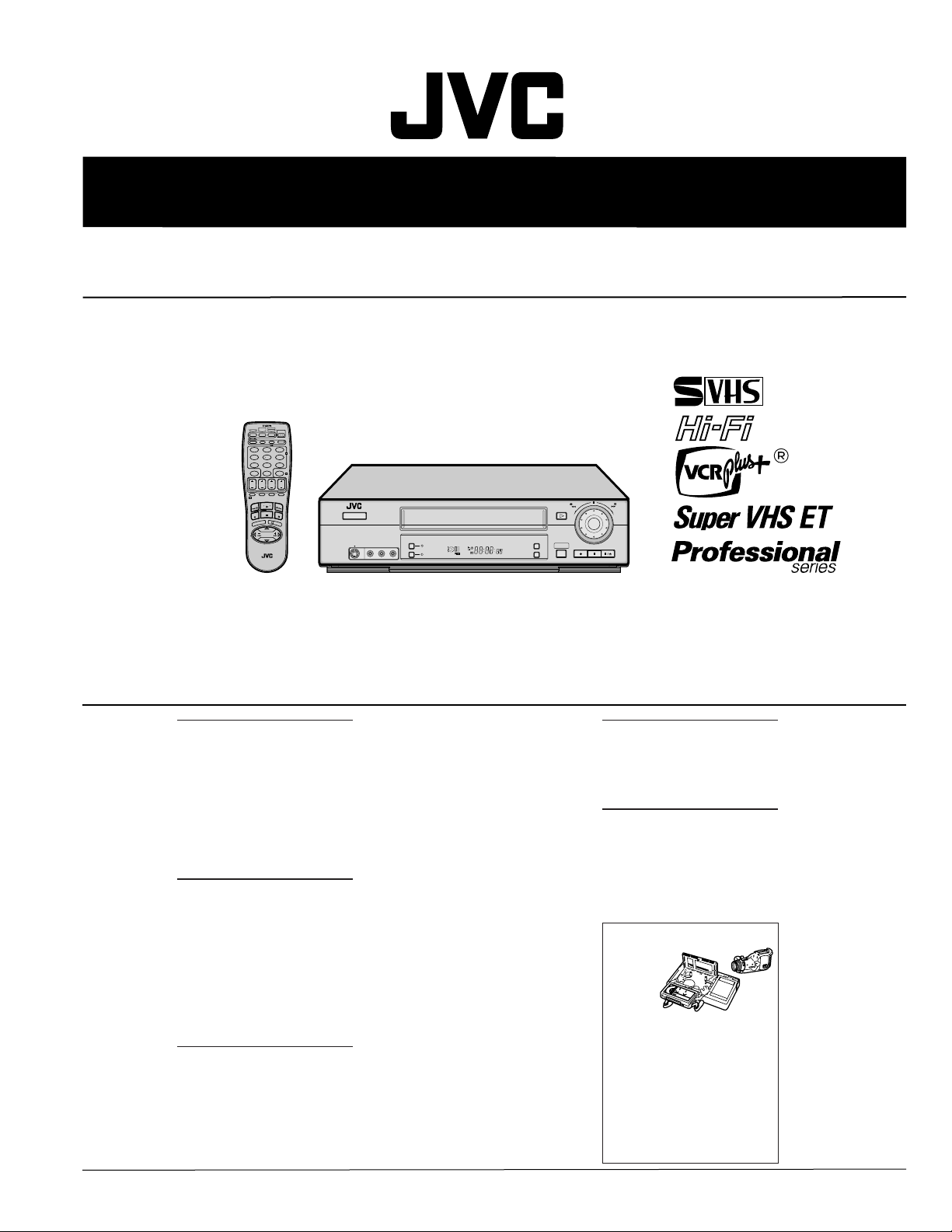
VIDEO CASSETTE RECORDER
SR-V10U
MBRSET
CABLE/
DBS
A/B
TV
POWER
TV/VCR
DISPLAY
A. MONITOR
123
2
456
DBS
DAILY
WEEKLY
89
7
AUX
C.RESET
4
CANCEL
TIMER
0
START STOP DATE
CH
EXPRESS PROGRAMMING
PROG
PROG SP/EP SKIP SEARCH
1
CHECK
PLAY
F
W
F
E
R
R
T
V
V
O
L
–
C
E
U
N
E
M
SHUTTLE
MULTI BRAND
REMOTE CONTROL UNIT
STOP
PAUSE
3
O
K
C
H
V
+
T
PLUS
+
L
O
V
V
T
–
T
H
V
C
POWER
VIDEO (MONO)L—AUDIO—R
REC LINK
DIGITAL TBC/NR
SP EP
VCR
S VIDEO
PLAY
A.DUB
24HR QUICK
PROGRAM
INSERT
Regarding service information other than these sections, refer to the HR-S5900U service manual (No.82848).
Also, be sure to note important safety precautions provided in the service manual.
REW
–
REC PAUSE STOP/EJECT
FF
+
CH– /+
PUSH / TURN
SPECIFICATIONS
GENERAL
Power requirement : AC 120 V` , 60 Hz
Power consumption
Power on : 20 W
Power off : 2.5 W
Temperature
Operating : 5°C to 40°C (41°F to 104°F)
Storage : –20°C to 60°C (–4°F to140°F)
Operating position : Horizontal only
Dimensions (W x H x D) : 400 mm x 94 mm x 283 mm
Weight : 3.4 kg
Format : S-VHS/VHS NTSC standard
Maximum recording time
SP : 210 min. with ST-210 video
EP : 630 min. with ST-210 video
VIDEO/AUDIO
Signal system : NTSC-type color signal and
Recording/
Playback system : DA-4 (Double Azimuth) head
Signal-to-noise ratio : 45 dB
Horizontal resolution
VHS : 230 lines
S-VHS : 400 lines
Frequency range
Normal audio : 70 Hz to 10,000 Hz
Hi-Fi audio : 20 Hz to 20,000 Hz
Input/Output : RCA connectors
TUNER
Tuning system : Frequency-synthesized tuner
Channel coverage
VHF : Channels 2–13
UHF : Channels 14–69
CATV : 113 Channels
RF output : Channel 3 or 4 (switchable;
cassette
cassette
EIA monochrome signal,
525 lines/60 fields
helical scan system
(IN x 2, OUT x 1)
S-video connectors
(IN x 2, OUT x 1)
preset to Channel 3 when
shipped) 75 ohms,
unbalanced
TIMER
Clock reference : Quartz
Program capacity : 1-year programmable timer/
Memory backup time : Approx. 6 months
ACCESSORIES
Provided accessories : Infrared remote control unit,
Specifications shown are for SP mode unless specified
otherwise.
E. & O.E. Design and specifications subject to change without
notice.
Usable cassettes
Full-Size VHS
T-30 (ST-30**)
T-60 (ST-60**)
T-9 0
T-120 (ST-120**)
T-160 (ST-160**)
ST-210**
Compact VHS*
TC-20 (ST-C20**)
TC-30 (ST-C30**)
TC-40 (ST-C40**)
* Compact VHS camcorder recordings can be
played on this video recorder. Simply place the
recorded cassette into a VHS Cassette Adapter
and it can be used just like any full-sized VHS
cassette.
** This VCR can record on regular VHS and Super
VHS cassettes. While only VHS signals can be
recorded on regular VHS cassettes
and Super VHS signals can be recorded and
played back using Super VHS cassettes.
1)
By using the S-VHS ET function, it is possible to record and
play back with S-VHS picture quality on VHS cassettes on
this VCR.
8 programs
Estimated figure based on
supplied fresh battery; actual
performance may differ.
“AA” battery x 2,
Lithium battery CR2025,
S-video cable (4-pin),
RF cable (F-type),
Audio/video cable,
BNC/RCA adapter x 2
1)
, both VHS
This service manual is printed on 100% recycled paper.
COPYRIGHT © 2002 VICTOR COMPANY OF JAPAN, LTD
No.82899
January 2002
Page 2
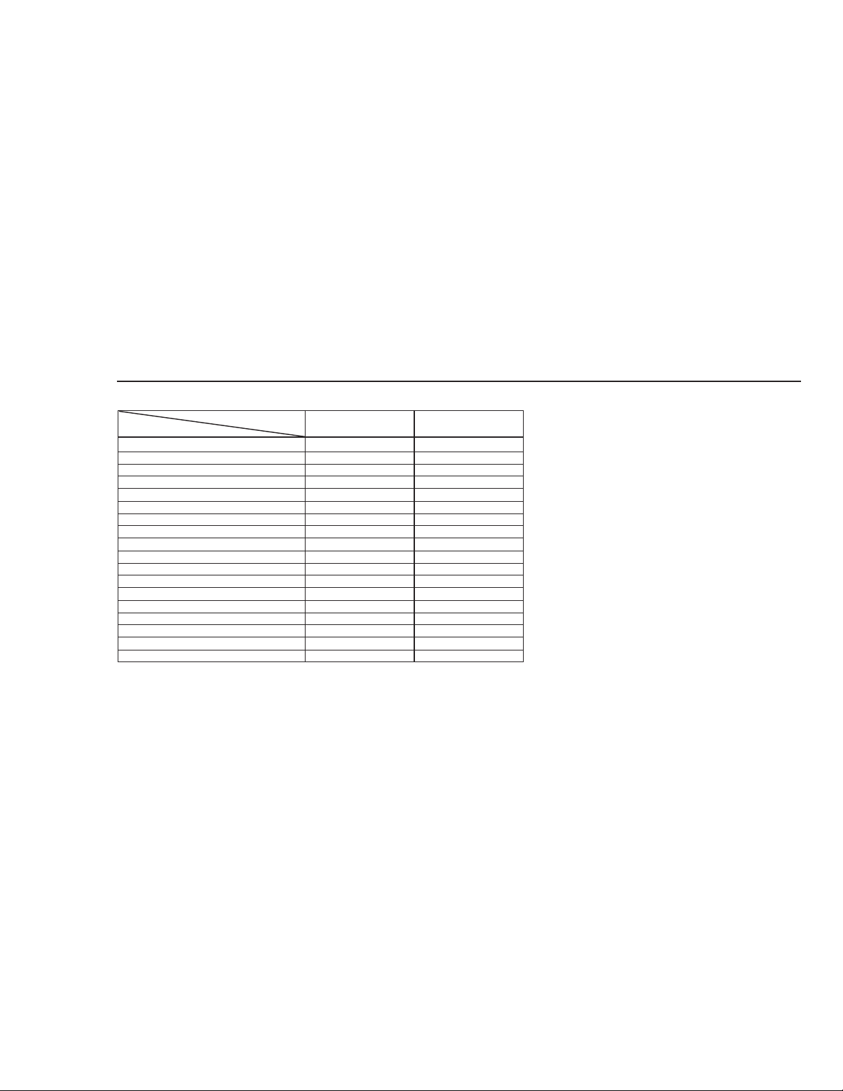
TABLE OF CONTENTS
DIFFERENT TABLE .......................................................................................................................................................................... (1 to 2)
4.CHART AND DIAGRAMS (4-1 to 4-8)
4.1 MAIN, PAUSE, C.BOX AND LI BATTERY CIRCUIT BOARDS..........................................................................................................4-1
4.2 MAIN (TUNER/DEMOD) SCHEMATIC DIAGRAM .............................................................................................................................4-4
4.3 3D DIGITAL/2M SCHEMATIC DIAGRAM ...........................................................................................................................................4-6
4.4 3D DIGITAL/2M CIRCUIT BOARD .....................................................................................................................................................4-8
5.PARTS LIST (5-1 to 5-14)
5.1 PACKING AND ACCESSORY ASSEMBLY<M1> ..............................................................................................................................5-1
5.2 FINAL ASSEMBLY <M2>....................................................................................................................................................................5-2
5.3 MECHANISM ASSEMBLY <M4> ........................................................................................................................................................5-4
5.4 ELECTRICAL PART LIST ...................................................................................................................................................................5-6
MAIN BORAD ASSEMBLY <03> ........................................................................................................................................................ 5-6
3D DIGITAL/2M BORAD ASSEMBLY <05> ......................................................................................................................................5-12
AC HEAD BORAD ASSEMBLY <12> ............................................................................................................................................... 5-13
DEMOD BORAD ASSEMBLY <14>..................................................................................................................................................5-13
S JACK BORAD ASSEMBLY <36>...................................................................................................................................................5-14
ADV.JOG BORAD ASSEMBLY <38>................................................................................................................................................ 5-14
LOADING MOTOR BORAD ASSEMBLY <55>.................................................................................................................................5-14
R PAUSE BORAD ASSEMBLY <91>................................................................................................................................................ 5-14
C.BOX BORAD ASSEMBLY <92> ....................................................................................................................................................5-14
LI BATTERY BORAD ASSEMBLY <93> ...........................................................................................................................................5-14
The following table indicate main different points between models HR-S5900U and SR-V10U.
ITEM
BODY COLOR BLACK DARK GRAY
REPEAT TYPE / TIMES FULL / 100 FULL / NO LIMIT
DIGITAL 3R NOT USED USED
TBC / NR NOT USED USED
FRAME MEMORY NOT USED USED
REMOTE IN/OUT NOT USED USED
LI BATTERY FOR BACKUP NOT USED LI BATTERY
REC RESUME NOT USED USED
REPEAT REC / PLAY NOT USED USED
SERIES REC / PLAY NOT USED USED
MODE LOCK NOT USED USED
DAY/TIME INSERT NOT USED USED
REC SAFETY ON/OFF NOT USED USED
LAST FUNCTION MEMORY NOT USED USED
ON SCREEN(REC/PLAY) OFF NOT USED USED
WIRED RCU NOT USED USED
SATELLITE AUT O RECORDING NOT USED USED
DAILY TIMER REC NOT USED USED
MODEL
HR-S5900U
SR-V10U
1
Page 3

The following tables indicate different parts number between models HR-S5900U and SR-V10U.
PACKING AND ACCESSOR Y ASSEMBLY<M1>
PACKING AND ACCESSORY ASSEMBLY<M1> is indicated on the parts list.
FINAL ASSEMBL Y<M2>
FINAL ASSEMBLY<M2> is indicated on the parts list.
MECHANISM ASSEMBL Y<M4>
MECHANISM ASSEMBLY<M4> is indicated on the parts list.
MAIN BOARD ASSEMBLY<03>
REF
!
ITEM
NO.
PW1 MAIN BOARD ASSY LPA10134-03D1 LPA10134-12A1
MODEL
HR-S5900U
SR-V10U
2D DIGITAL BOARD ASSEMBLY<05>
REF
!
ITEM
NO.
PW1 2D DIGITAL BOARD ASSY LPA10090-05A ––
MODEL
HR-S5900U
SR-V10U
3D DIGITAL/2M BOARD ASSEMBLY<05>
!
REF
ITEM
NO.
PW1
3D DIGITAL/2M BOARD ASSY
MODEL
HR-S5900U
SR-V10U
–– LPA10105-02A
R.PAUSE BOARD ASSEMBLY<91>
REF
!
ITEM
NO.
PW2 R.PAUSE BOARD ASSY LPA10134-03C2 *LPA10134-03E2
MODEL
HR-S5900U
SR-V10U
C.BOX BOARD ASSEMBLY<92>
REF
!
ITEM
NO.
PW3 C.BOX BOARD ASSY LPA10134-03C3 *LPA10134-03E3
MODEL
HR-S5900U
SR-V10U
LI BATTERY BOARD ASSEMBLY<93>
REF
!
ITEM
NO.
PW4 LI BATTERY BOARD ASSY –– LPA10134-12A4
MODEL
HR-S5900U
SR-V10U
Notes: Mark –– is not used.
Mark * reference model was also changed.
2
Page 4

JVC SERVICE & ENGINEERING COMPANY OF AMERICA
DIVISION OF JVC AMERICAS CORP.
Head office
East Coast
Midwest
West Coast
Atlanta
Hawaii
Head office
Montreal
Vancouver
:
1700 Valley Road Wayne, New Jersey 07470-9976
10 New Maple Avenue Pine Brook, New Jersey 07058-9641
:
705 Enterprise Street Aurora, Illinois 60504-8149
:
5665 Corporate Avenue Cypress, California 90630-0024
:
1500 Lakes Parkway Lawrenceville, Georgia 30043-5857
:
2969 Mapunapuna Place Honolulu, Hawaii 96819-2040
:
JVC CANADA INC.
:
21 Finchdene Square Scarborough, Ontario M1X 1A7
:
16800 Rte Trans-Canadienne, Kirkland, Quebec H9H 5G7
:
13040 Worster Court Richmond, B.C. V6V 2B3
(973)317-5000
(973)396-1000
(630)851-7855
(714)229-8011
(770)339-2582
(808)833-5828
(416)293-1311
(514)871-1311
(604)270-1311
S40895-04
Printed in Japan
 Loading...