

Page 1
SERVICE MANUAL
DVD VIDEO RECORDER & VIDEO CASSETTE RECORDER
YD01220045
SR-MV30US
DVDTV
CABLE/DBS
TV/CBL/DBS
DVD
VCR
VCR
/DVD
TIMER
/DVD
TIMER
NUMBER/ TV CH / DVD CHNUMBER/ TV CH / DVD CH
2
3
1
ABC DEF
5
6
4
JKL MNO
GHI
8
9
7
TUV
PQRS WXYZ
0
MEMO/MARK
AUX
CANCEL
PROG/CHECK
DISPLAYON SCREEN
PROGRESSIVE
VCR PLUS+
SCAN
TION
VIGA
U
M
N
NA
EN
E
U
P M
O
T
ENTER
S
E
T U
PREVIOUS NEXT
SLOW
REMAIN REC
REC MODE
ANGLE
LIVE CHECK
TV/VCR
TV/DVD
For disassembling and assembling of MECHANISM ASSEMBLY, refer to the SERVICE MANUAL No.86700(MECHANISM ASSEMBLY).
Regarding service information other than these sections, refer to the service manual No. YD006 (DR-MV1SUS).
Also, be sure to note important safety precautions provided in the service manual.
N
R
TU
P
E
R
SLOW
PLAY/SELECT
CLEAR
PAUSESTOP/
SUBTITLE
AUDIO
TV/CBL/DVD
TV
CH
VOL.
TV
POWER
VCR EJECT
VCR/DVD TIMER VCR REC OPEN/CLOSE STOP PLAY
PULL-OPEN
DVD
S-VIDEO
VIDEO (MONO) L - AUDIO - R
F-1
TIMER DVD DVDREC VCR DUBBING
REMAIN
REC PAUSE REW FF
REC MODE SLOW
<< >>
PULL-OPEN
REC LINK
DV IN
CH
DVD
SR-MV30US [D3RS29]
TABLE OF CONTENTS
1 PRECAUTION. . . . . . . . . . . . . . . . . . . . . . . . . . . . . . . . . . . . . . . . . . . . . . . . . . . . . . . . . . . . . . . . . . . . . . . . . 1-3
2 SPECIFIC SERVICE INSTRUCTIONS . . . . . . . . . . . . . . . . . . . . . . . . . . . . . . . . . . . . . . . . . . . . . . . . . . . . . . 1-3
3 DISASSEMBLY . . . . . . . . . . . . . . . . . . . . . . . . . . . . . . . . . . . . . . . . . . . . . . . . . . . . . . . . . . . . . . . . . . . . . . . 1-3
4 ADJUSTMENT . . . . . . . . . . . . . . . . . . . . . . . . . . . . . . . . . . . . . . . . . . . . . . . . . . . . . . . . . . . . . . . . . . . . . . . . 1-4
5 TROUBLESHOOTING . . . . . . . . . . . . . . . . . . . . . . . . . . . . . . . . . . . . . . . . . . . . . . . . . . . . . . . . . . . . . . . . . . 1-5
COPYRIGHT © 2004 Victor Company of Japan, Limited
No.YD012
2004/5
Page 2
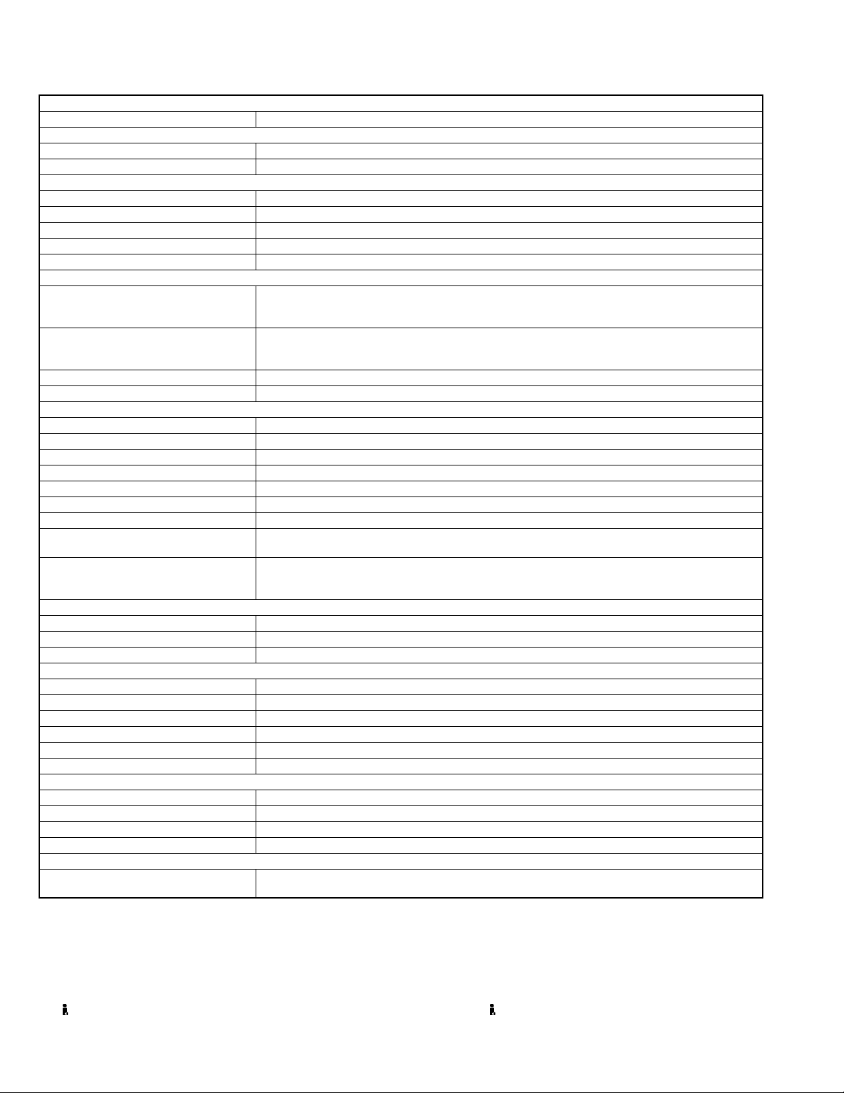
SPECIFICATION
GENERAL
Power requirement AC 120 V, 60 Hz
Power consumption
Power on 46 W
Power off 16.5 W
Temperature
Operating 5°C to 35°C (41°F to 95°F)
Storage -20°C to 60°C (-4°F to140°F)
Operating position Horizontal only
Dimensions (W × H × D) 435 mm × 96 mm × 347 mm (17-3/16" x 3-13/16" × 13-11/16")
Weight 6.2 kg (13.7 lbs)
VIDEO/AUDIO (DVD deck)
Recording format DVD-RAM: DVD Video Recording format
DVD-RW: DVD-Video format, DVD Video Recording format
Recording time Maximum 8 hours (with 4.7 GB disc)
Audio recording system Dolby Digital (2 ch), Linear PCM (XP mode only)
Video recording compression system MPEG2 (CBR/VBR)
Input/Output
S-video input Y: 0.8 - 1.2 Vp-p, 75 Ω, C: 0.2 - 0.4 Vp-p, 75 Ω
S-video output Y: 1.0 Vp-p, 75 Ω, C: 0.3 Vp-p, 75 Ω
Video input 0.5 - 2.0 Vp-p, 75 Ω (pin jack)
Video output 1.0 Vp-p, 75 Ω (pin jack)
Audio input -8 dB, 50 kΩ (pin jack), Corresponding to mono (left)
Audio output -8 dB, 1 kΩ (pin jack)
i.Link 4-pin for DV input
Component video output Y: 1.0 Vp-p, 75 Ω, CB/CR, PB/PR: 0.7 Vp-p, 75 Ω
Digital audio output Optical: -18 dBm, 660 nm, Coaxial: 0.7 Vp-p, 75 Ω
VIDEO/AUDIO (VCR Deck)
Signal system NTSC color signal and EIA monochrome signal, 525 lines/60 fields
Recording system DA4 (Double Azimuth) head helical scan system
Format S-VHS/VHS NTSC standard
Maximum recording time
(SP) 210 min. with ST-210 video cassette
(EP) 630 min. with ST-210 video cassette
Signal-to-noise ratio 45 dB
Horizontal resolution 230 lines(VHS) / 400 lines(S-VHS)
Frequency range 70 Hz to 10,000 Hz (Normal audio) 20 Hz to 20,000 Hz (Hi-Fi audio)
Input/Output RCA connectors: IN × 2, OUT × 1
TUNER/TIMER
Tuning system Frequency synthesized tuner
Channel coverage VHF: Channels 2 - 13, UHF: Channels 14 - 69,CATV: 113 Channels
RF output Channel 3 or 4 (switchable; preset to Channel 3 when shipped) 75 Ω, unbalanced
Memory backup time Approx. 5 seconds
ACCESSORIES
Provided accessories BNC/RCA adapter
(XP): Approx. 1 hour, (SP): Approx. 2 hours, (LP): Approx. 4 hours
(EP): Approx. 6 hours, (FR): Approx. 1 hour - 8 hours
Corresponding to Dolby Digital and DTS Digital Surround
Bit stream Selectable in digital audio output setting menu
• Specifications shown are for SP mode unless otherwise specified.
• E.& O.E. Design and specifications subject to change without notice.
• VCR Plus+, C
• The VCR Plus+ system is manufactured under license from Gemstar Development Corporation.
TM
•DSS
3
and PlusCode are registered trademarks of Gemstar Development Corporation.
is an official trademark of DIRECTV, Inc., a unit of GM Hughes Electronics. DISH NetworkTM is a trademark of Echostar Communications
Corporation.
• Manufactured under license from Dolby Laboratories. "Dolby" and the double-D symbol are trademarks of Dolby Laboratories.
• "DTS" and "DTS Digital Out" are trademarks of Digital Theater Systems, Inc.
• (i.Link) refers to the IEEE1394-1995 industry specification and extensions thereof. The logo is used for products compliant with the i.Link standard.
DVD-R: DVD-Video format
Corresponding to copy protection
× 2, RF cable, Audio/video cable, S-video cable, Controller,
Infrared remote control unit, “AA” battery
× 2
1-2 (No.YD012)
Page 3

SECTION 1
PRECAUTION
Please refer to "DR-MV1SUS No.YD006" about this section.
SECTION 2
SPECIFIC SERVICE INSTRUCTIONS
Please refer to "DR-MV1SUS No.YD006" about this section except a written item.
2.1 DIFFERENT TABLE OF FEATURE
The following table indicates main different points between models DR-MV1SUS and SR-MV30US.
MODEL NAME DR-MV1SUS SR-MV30US
BODY COLOR PURE SILVER GRAY
ILLUMINATION COLOR USED(BLUE) NOT USED
VIDEO SYSTEM VHS S-VHS
S-VHS ET NOT USED USED
SQPB USED NOT USED
TIME BASE CORRECTOR NOT USED USED
3R PICTURE(DIGITAL or ANALOG) NOT USED USED
3D DIGITAL Y/C SEPARATION NOT USED USED
2MB FRAME MEMORY NOT USED USED
SECTION 3
DISASSEMBLY
Please refer to "DR-MV1SUS No.YD006" about this section.
(No.YD012)1-3
Page 4

SECTION 4
ADJUSTMENT
Please refer to "DR-MV1SUS No.YD006" about this section except a written item.
4.1 Electrical adjustment (VHS SECTION)
Note:
The following adjustment procedures are not only necessary
after replacement of consumable mechanical parts or board
assemblies, but are also provided as references to be referred
to when servicing the electrical circuitry.
In case of trouble with the electrical circuitry, always begin a
service by identifying the defective points by using the measuring instruments as described in the following electrical adjustment procedures. After this, proceed to the repair,
replacement and/or adjustment. If the required measuring instruments are not available in the field, do not change the adjustment parts (variable resistor, etc.) carelessly.
4.1.1 Servo circuit
4.1.1.1 Switching point
Signal (A1)
Mode (B) • PB
Equipment (C) • Oscilloscope
Measuring point (D) • VIDEO OUT terminal (75 ohm terminated)
External trigger (E) • TP111 (D.FF)
Adjustment part (F) • Jig RCU: Code “51”or “52”
Specified value (G) • 8.0 ± 0.5H
Adjustment tool (H) • Jig RCU [PTU94023B]
• Stairstep signal
(A2)
• Alignment tape(EP,stairstep,NTSC) [MHP-L]
• TP106 (PB. FM)
(1) Play back the signal (A1) of the alignment tape (A2).
(2) Apply the external trigger signal to D.FF (E) to observe the
VIDEO OUT waveform and V.PB FM waveform at the
measuring points (D1) and (D2).
(3) Set the VCR to the manual tracking mode.
(4) Adjust tracking so that the V.PB FM waveform becomes
maximum.
(5) Transmit the code (F) from the Jig RCU to adjust so that the
trigger point of the VIDEO OUT wavefome is changed from
the trailing edge of the V.sync signal becomes the specified
value (G).
(6) Set the VCR to the stop mode.
Trigger point
Switching point
V.sync
4.1.2 Video circuit
4.1.2.1 EE Y/PB Y level
Signal (A1)
Mode (B1)
Equipment (C) • Oscilloscope
Measuring point (D) • Y OUT terminal (75 ohm terminated)
EVR mode
EVR address
Specified value (G) • 1.00 ± 0.05 Vp-p
Adjustment tool (H) • Jig RCU [PTU94023B]
• Ext. S-input
(A2)
• Ext. input
(A3)
• Color (colour) bar signal [NTSC]
• EE SP
(B2)
•S-VHS SP
(B3)
•VHS SP
(F1)
• Jig code “57”
(F2)
• A : 11
(F3)
• Jig code “21” twice
(F4)
• Jig code “18” or “19” (Channel +/-)
(1) Input the signal (A3) from the input point (A1).
(2) Set the VCR to the mode (B1).
(3) Observe the Y OUT waveform at the measuring point (D).
(4) Set the VCR to the EVR mode by transmitting the code (F1)
from the Jig RCU.
(5) Set the EVR address to (F2) by transmitting the code (F3)
from the Jig RCU.
(6) Transmit the code (F4) from the Jig RCU to adjust so that
the Y level of the Y OUT waveform becomes the specified
value (G).
(7) Release the EVR mode of the VCR by transmitting the
code (F1) from the Jig RCU again. (When the EVR mode
is released, the adjusted data is memorized.)
(8) Input the signal (A3) from the input point (A2).
(9) Repeat steps (3) to (7) in the mode (B1).
(10) Record the signal (A3) in the mode (B2), and play back the
recorded signal.
(11) Set the VCR to the manual tracking mode.
(12) Repeat steps (3) to (7) in the mode (B2).
(13) Record the signal (A3) in the mode (B3), and play back the
recorded signal.
(14) Set the VCR to the manual tracking mode.
(15) Repeat steps (3) to (7) in the mode (B3).
1-4 (No.YD012)
Fig.4-1a Switching point
V. rate
Y level
H. rate
Fig.4-1b EE Y/PB Y lebel
Page 5

4.1.3 Audio circuit
Note:
• GND (Ground) should be taken from the Tuner shield
case.
4.1.3.1 Audio REC FM
Signal (A1)
Mode (B) • S-VHS EP
Equipment (C) • Oscilloscope
Measuring point (D) • TP2253 (A. PB FM) [Main board]
External trigger (E) • TP111 (D.FF)
Adjustment part (F) • VR2251 (FMA REC LEVEL)
Specified value (G1)
• Ext. input
• Audio: No signal
(A2)
• Video: Color (colour) bar signal [NTSC]
(A3)
•TBC:OFF
• 350 ± 50 mVp-p
(G2)
• More than 200 mVp-p
(1) Apply the external trigger signal to D.FF (E) to observe the
Audio PB FM waveform at the measuring point (D).
SECTION 5
TROUBLESHOOTING
(2) Record the signal (A3) with no audio signal input in the
mode (B), and play back the recorded signal.
(3) Set the VCR to the manual tracking mode.
(4) If the A.PB FM level is not within the specified value (G1),
perform the adjustment in a following procedure.
(5) Adjust the Adjustment part (F) so that the A. PB FM level of
the higher channel level becomes the specified value (G1).
(Adjust before recording, then confirm it by playing back.)
(6) If the specified value (G1) is not obtained, adjust the Ad-
justment part (F) so that the waveform level of the lower
channel level becomes the specified value (G2). (Adjust
before recording, then confirm it by playing back.)
Specified
value (G2)
V. rate
Specified
value (G1)
Fig.4-1c Audio REC FM
Please refer to "DR-MV1SUS No.YD006" about this section.
(No.YD012)1-5
Page 6

JVC SERVICE & ENGINEERING COMPANY OF AMERICA
DIVISION OF JVC AMERICAS CORP.
www.jvcservice.com(US Only)
JVC CANADA INC.
Head office : 21 Finchdene Square Scarborough, Ontario M1X 1A7 (416)293-1311
(No.YD012)
Printed in Japan
WPC
 Loading...