

Page 1

AUDIO/VIDEO CONTROL RECEIVER
English
RECEPTURE DE COMMANDE AUDIO/VIDEO
RX-D412B
INSTRUCTIONS
MANUEL D’INSTRUCTIONS
LV T1572-002B
[C]
Page 2
Warnings, Cautions, and Others
WARNING: TO REDUCE THE RISK OF FIRE
OR ELECTRIC SHOCK, DO NOT EXPOSE
THIS APPLIANCE TO RAIN OR MOISTURE.
CAUTION: TO REDUCE THE RISK OF ELECTRIC SHOCK,
DO NOT REMOVE COVER (OR BACK).
NO USER SERVICEABLE PARTS INSIDE.
REFER SERVICING TO QUALIFIED SERVICE PERSONNEL.
RISK OF ELECTRIC SHOCK
DO NOT OPEN
The lightning flash with arrowhead symbol,
within an equilateral triangle is intended to
alert the user to the presence of uninsulated
"dangerous voltage" within the product's
enclosure that may be of sufficient
magnitude to constitute a risk of electric
shock to persons.
The exclamation point within an equilateral
triangle is intended to alert the user to the
presence of important operating and
maintenance (servicing) instructions in the
literature accompanying the appliance.
CAUTION
For U.S.A
This equipment has been tested and found to comply with the limits
for a Class B digital device, pursuant to part 15 of the FCC Rules.
These limits are designed to provide reasonable protection against
harmful interference in a residential installation.
This equipment generates, uses and can radiate radio frequency
energy and, if not installed and used in accordance with the
instructions, may cause harmful interference to radio
communications. However, there is no guarantee that interference
will not occur in a particular installation. If this equipment does cause
harmful interference to radio or television reception, which can be
determined by turning the equipment off and on, the user is
encouraged to try to correct the interference by one or more of the
following measures:
- Reorient or relocate the receiving antenna.
- Increase the separation between the equipment and receiver.
- Connect the equipment into an outlet on a circuit different from that
to which the receiver is connected.
- Consult the dealer or an experienced radio/TV technician for help.
Mises en garde, précautions et indications diverses
CAUTION
Changes or modifi cations not approved by JVC could void the
user’s authority to operate the equipment.
ATTENTION
Des changements ou modifi cations non approuvés par JVC
pourront invalider l’autorité de l’utilisateur à opérer cet
appareil.
CAUTION
To reduce the risk of electrical shocks, fi re, etc.:
1. Do not remove screws, covers or cabinet.
2. Do not expose this appliance to rain or moisture.
ATTENTION
Afi n d’éviter tout risque d’électrocution, d’incendie, etc.:
1. Ne pas enlever les vis ni les panneaux et ne pas ouvrir le
coffret de l’appareil.
2. Ne pas exposer l’appareil à la pluie ni à l’humidité.
Caution–– STANDBY/ON button!
Disconnect the mains plug to shut the power off completely (the
standby lamp goes off). When installing the apparatus, ensure
that the plug is easily accessible. The STANDBY/ON button
in any position does not disconnect the mains line.
• When the unit is on standby, the standby lamp lights red.
• When the unit is turned on, the standby lamp goes off.
The power can be remote controlled.
Attention—Touche STANDBY/ON!
Déconnectez la fi che secteur pour mettre l’appareil
complètement hors tension (le témoin d’attente s’éteint). Lors
de l’installation de l’appareil, assurez-vous que la fi che soit
facilement accessible. La touche STANDBY/ON dans
n’importe quelle position ne déconnecte pas l’appareil du
secteur.
• Quand l’appareil est en mode d’attente, le témoin d’attente
s’allume en rouge.
• Quand l’appareil est sous tension, le témoin d’attente
L’alimentation ne peut pas être commandée à distance.
Note to CATV system installer:
This reminder is provided to call the CATV system installer’s
attention to Section 820-40 of the NEC which provides
guidelines for proper grounding and, in particular, specifi es that
the cable ground shall be connected to the grounding system of
the building, as close to the point of cable entry as practical.
G-1
s’éteint.
Declaration of Conformity:
Tr ade Name: JVC
Model Number: RX-D412B
Responsible Party: JVC Americas Corp.
Address: 1700 Valley Road, Wayne New Jersey 07470
Telephone Number: 973-317-5000
This device complies with Part 15 of the FCC Rules. Operation
is subject to the following two conditions:
(1) This device may not cause harmful interference.
(2) This device must accept any interference received, including
interference that may cause undesired operation.
For Canada/pour Le Canada
THIS DIGITAL APPARATUS DOES NOT EXCEED THE
CLASS B LIMITS FOR RADIO NOISE EMISSIONS FROM
DIGITAL APPARATUS AS SET OUT IN THE INTERFERENCECAUSING EQUIPMENT STANDARD ENTITLED “DIGITAL
APPARATUS,” ICES-003 OF THE DEPARTMENT OF
COMMUNICATIONS.
CET APPAREIL NUMERIQUE RESPECTE LES LIMITES
DE BRUITS RADIOELECTRIQUES APPLICABLES AUX
APPAREILS NUMERIQUES DE CLASSE B PRESCRITES
DANS LA NORME SUR LE MATERIEL BROUILLEUR;
“APPAREILS NUMERIQUES”, NMB-003 EDICTEE PAR LE
MINISTRE DES COMMUNICATIONS.
[European Union Only]
[Union européenne seulement]
Page 3

English
Introduction
We would like to thank you for purchasing one of our JVC products.
Before operating this unit, read this manual carefully and thoroughly to obtain the best possible performance from your unit,
and retain this manual for future reference.
DCDi technology
Features
Hybrid Feedback Digital Amplifier
RX-D412B features the JVC-exclusive Hybrid Feedback Digital
Amplifier. Premium-grade parts and devices, and special
internal construction assure you will enjoy superior sound.
DCDi (Directional Correlational Deinterlacing) technology,
developed by Faroudja, eliminates jagged edges generated
in progressive scanning conversion. With DCDi, you can enjoy
clear and smooth video images on your display. For RX-D412B,
this function is applied only when the NTSC analog video
signals are transmitted to the receiver.
Compatible with HDMI*
The HDMI (High-Definition Multimedia Interface) is the
standard interface for the next-generation TV. By connecting
the source components, this receiver, and TV with the HDMI
cables, digital video signals and audio signals (including Dolby
Digital, DTS) are transmitted through the cables. You can
transmit digital video signal and audio signal without AD/DA
conversion with easy connection.
As RX-D412B supports up to HDMI version 1.1, this receiver
can digitally receive 5.1-channel PCM with fs 96 kHz and 2channel PCM with fs 192 kHz. (These PCM signals are referred
to as “multi-channel PCM” in this instructions.) You can enjoy
digital sound without deterioration. In addition, this receiver
is compatible with HDCP** (High-bandwidth Digital Content
Protection), and HDCP contents can be viewed if you connect
an HDCP-compatible TV to this receiver.
* HDMI, the HDMI logo and High-Definition Multimedia
Interface are trademarks or registered trademarks of HDMI
Licensing LLC.
** HDCP is the abbreviation of “High-bandwidth Digital
Content Protection,” and is the high-reliable copy control
technology licensed by Digital Content Protection, LLC.
7.1 channel DAP (Digital Acoustic Processor)
Sound field simulation technology allows precise ambience
recreation of existing theaters and halls. Thanks to the highperformance DSP (Digital Signal Processor) and high-capacity
memory, you can enjoy 7.1-channel surround by playing
2-channel or multi-channel software.
Precise Surround Setup
Precise Surround Setup is a newly-developed JVC solution for
quick, easy and systematic optimization of surround sound.
By using Precise Surround Setup, you can enjoy the best
possible surround performance. Precise Surround Setup
measures the listening environment accurately with the
dedicated earphone-type microphones and adjusts the
speaker settings automatically.
CC (Compression Compensative) Converter
CC Converter eliminates jitter and ripples, achieving a drastic
reduction in digital distortion by processing the digital music
data in 24 bit–quantization and by expanding the sampling
frequency to 128 kHz (for fs 32 kHz signals)/176.4 kHz (for fs
44.1 kHz signals)/192 kHz (for fs 48 kHz signals). By using the
CC Converter, you can obtain a natural sound field from any
source.
K2 technology
K2 technology has been designed to enable natural audio
reproduction, achieving a drastic reduction in digital
distortion and creating original sound ambience with high
precision.
Precautions
Power sources
• When unplugging the receiver from the wall outlet, always
pull the plug, not the AC power cord.
• Do not handle the AC power cord with wet hands.
• If you are not going to operate the receiver for an extended
period of time, unplug the AC power cord from the wall
outlet.
Ventilation
The seven high power amplifiers built in this receiver will
generate heat inside the cabinet.
For safety, observe the following carefully:
• Make sure there is good ventilation around the receiver.
Poor ventilation could overheat and damage the receiver.
• Do not block the ventilation openings or holes. (If the
ventilation openings or holes are blocked by a newspaper or
cloth, etc., the heat may not be able to get out.)
Others
• Should any metallic object or liquid fall into the receiver,
unplug the receiver and consult your dealer before
operating any further.
• Do not use this receiver in a bathroom or places with water.
• Do not place any containers filled with water or liquids (such
as cosmetics or medicines, flower vases, potted plants, cups,
etc.) on the top of this receiver.
• Do not disassemble the receiver since there are no user
serviceable parts inside.
If anything goes wrong, unplug the AC power cord and
consult your JVC dealer.
1
Page 4

English
Table of Contents
Parts identification ......................................................3
Getting started ............................................................6
Before installation .............................................................................6
Checking the supplied accessories .............................................6
Putting the batteries in the remote control .............................6
Connecting the antennas ............................................................... 7
Connecting the speakers ................................................................8
Connecting video components ....................................................9
Connecting the power cord ........................................................ 14
USB connection ............................................................................... 15
Precise Surround Setup ............................................16
Setting the speakers automatically .......................................... 16
Troubleshooting for Precise Surround Setup ....................... 19
Basic operations ........................................................20
1 Turn on the power .................................................................. 20
2 Select the source to play ......................................................20
3 Adjust the volume ..................................................................21
Selecting the video and audio input settings ...................... 21
Selecting the digital decode mode .......................................... 22
Turning off the sounds temporarily ......................................... 22
Changing the display brightness .............................................. 22
Turning off the power with the Sleep Timer ........................ 23
Making sounds natural ................................................................. 23
FM/AM tuner operations ...........................................24
Tuning in to stations manually .................................................. 24
Using preset tuning ....................................................................... 24
Selecting the FM reception mode ............................................ 25
Basic settings .............................................................29
Basic setting items .......................................................................... 29
Operating procedure .................................................................... 30
Setting the speakers ...................................................................... 30
Activating the EX/ES/PLIIx setting—EX/ES/PLIIx ................ 32
Selecting the main or sub channel—DUAL MONO ........... 32
Setting bass sound ......................................................................... 33
Using the Midnight mode—MIDNIGHT MODE ................... 33
Setting the digital input (DIGITAL IN) terminals—DIGITAL
IN 1/2/3 .......................................................................................34
Setting the Audio delay level—AUDIO DELAY .................... 34
Selecting the source for HDMI terminal and COMPONENT
VIDEO jacks—HDMI SELECT/CMPNT SELECT ................ 34
Selecting the output video signals—VIDEO OUTPUT ....... 34
Sound adjustments ...................................................35
Basic adjustment items ................................................................ 35
Operating procedure .................................................................... 35
Adjusting the speaker output levels ........................................ 36
Adjusting the equalization patterns—D EQ 63Hz/250Hz/
1kHz/4kHz/16kHz .................................................................... 36
Reinforcing the bass—BASS BOOST ........................................ 37
Attenuating the input signal—INPUT ATT ............................ 37
Adjusting the sound parameters for the Surround/DSP
modes .......................................................................................... 37
Creating realistic sound fields ..................................39
Reproducing theater ambience ................................................39
Introducing the Surround modes ............................................. 39
Introducing the DSP modes ....................................................... 41
Using the Surround/DSP modes ............................................... 42
Activating the Surround/DSP modes ...................................... 43
AV COMPU LINK remote control system .................45
Operating other JVC products ..................................47
Operating other manufacturers’ products ..............49
Troubleshooting ........................................................52
Specifications .............................................................54
XM Satellite Radio operations ..................................26
Preparation ....................................................................................... 26
Listening to the XM Satellite Radio .......................................... 26
Using preset tuning ....................................................................... 27
Changing the channel information ......................................... 28
2
Page 5
English
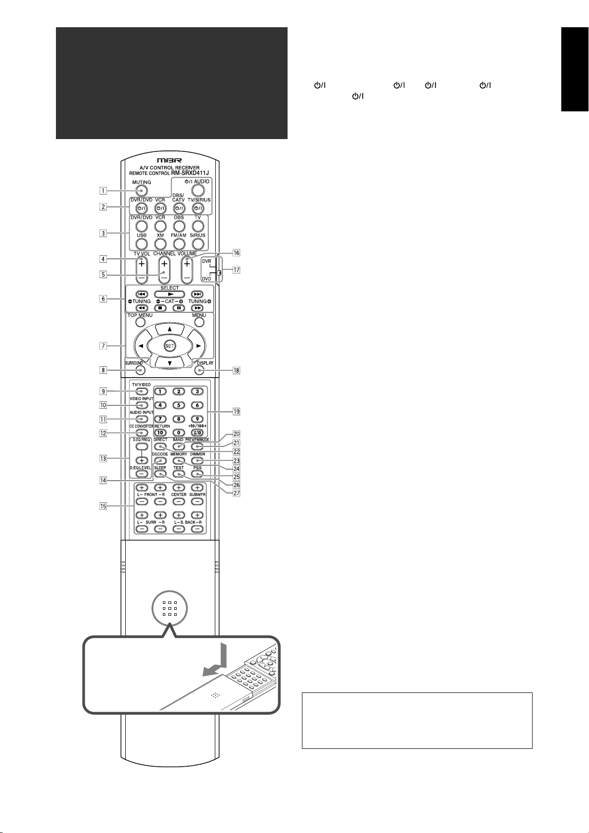
Parts identification
To open the cover of the
remote control, push here
then slide downward.
7 Remote control
See pages in parentheses for details.
MUTING button (22)
1
Standby/on buttons (16, 20, 47 – 51)
2
AUDIO, DVR/DVD , VCR , DBS/CATV ,
TV/SIRIUS
Source selecting buttons (20, 24, 26, 47 – 51)
3
DVR/DVD, VCR, DBS, TV, USB, XM, FM/AM, SIRIUS
TV VOL (volume) +/– button (47, 49)
4
CHANNEL +/– button (27, 47 – 51)
5
• Operating buttons for video components (47 – 51)
6
4, 3, ¢, 1, 7, 8, ¡
• Operating buttons for FM/AM tuner (24)
( TUNING, TUNING 9
• Operating buttons for XM Satellite Radio or SIRIUS
Satellite Radio (27, 47)
SELECT*, ( CAT, CAT 9
Operating buttons for DVD recorder or DVD player**
7
(48, 51)
TOP MENU, MENU, cursor buttons (3, 2, 5, ∞), SET
SURROUND button (44)
8
TV/VIDEO button (47, 49)
9
VIDEO INPUT button (21)
p
AUDIO INPUT button (21)
q
CC CONVERTER button (23)
w
Adjusting buttons for Digital Equalizer (36)
e
D.EQ FREQ, D.EQ LEVEL +/–
DECODE button (22)
r
Adjusting buttons for speaker and subwoofer output levels
t
(36)
FRONT L +/–, FRONT R +/–, CENTER +/–, SUBWFR +/–, SURR
L +/–, SURR R +/–, S.BACK L +/–, S.BACK R +/–
VOLUME +/– button (21)
y
Mode selector (48, 51)
u
DISPLAY button (28, 47)
i
• Numeric buttons (25, 27, 47 – 51)
o
1 – 10, 0, h10, +10/100+
• RETURN button (47)
BAND* button (47)
;
PREV*/FM MODE button (25 ,47)
a
DIRECT button (27)
s
DIMMER button (22)
d
MEMORY button (24, 27)
f
PSS (Precise Surround Setup) button (17)
g
TEST button (18, 36)
h
SLEEP button (23)
j
* For SIRIUS Satellite Radio only
** These buttons can be used for operating a DVD recorder
(JVC products only) or DVD player, with the mode selector
set to “DVR” or “DVD” (see page 48).
If these buttons do not function normally, use the remote
control supplied with your DVD recorder or DVD player.
Refer also to the manual supplied with the DVD recorder or
DVD player for details.
• When operating a DVD recorder (for JVC products
only), set the mode selector (u) to “DVR.”
• When operating a DVD player, set the mode selector
(u) to “DVD.”
3
Page 6
English
See pages in parentheses for details.
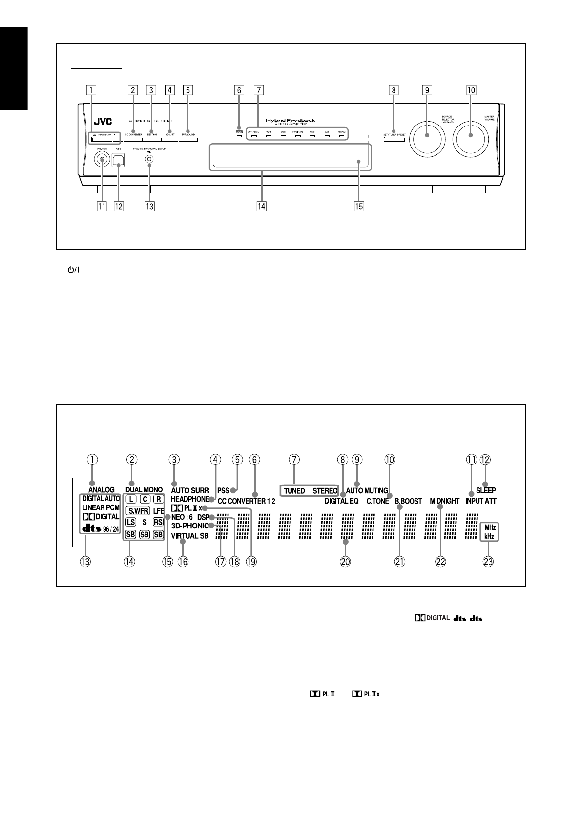
Front Panel
STANDBY/ON button and standby lamp (16, 20)
1
CC CONVERTER button (23)
2
SETTING button (30)
3
ADJUST button (35)
4
SURROUND button (44)
5
HDMI lamp (9, 21)
6
Source lamps
7
DVR/DVD, VCR, DBS, TV/SIRIUS, USB, XM, FM/AM
Display window
• SET button (20, 30, 35)
8
• TUNER PRESET button (25, 28)
• SOURCE SELECTOR (20, 25, 26)
9
• MULTI JOG (25, 28, 30, 35, 44)
MASTER VOLUME control (21)
p
PHONES jack (21)
q
USB terminal (15)
w
PRECISE SURROUND SETUP MIC jack (16)
e
Display window (see below)
r
Remote sensor (6)
t
ANALOG indicator (21)
1
DUAL MONO indicator (32)
2
AUTO SURR (surround) indicator (43)
3
HEADPHONE indicator (21, 42)
4
PSS (Precise Surround Setup) indicator (17)
5
CC CONVERTER 1 and CC CONVERTER 2 indicators (23)
6
FM/AM tuner operation indicators (24)
7
TUNED, STEREO
DIGITAL EQ indicator (36)
8
AUTO MUTING indicator (25)
9
C (center).TONE indicator (38)
0
INPUT ATT (attenuate) indicator (37)
-
SLEEP indicator (23)
=
4
Digital signal format indicators (21, 22, 40, 41)
~
DIGITAL AUTO, LINEAR PCM,
Signal and speaker indicators (23)
!
NEO:6 indicator (40)
@
VIRTUAL SB (surround back) indicator (43)
#
3D-PHONIC indicator (40, 41)
$
DSP indicator (41)
%
^
&
*
(
)
and indicators (39 – 41)
Main display
B (bass).BOOST indicator (37)
MIDNIGHT indicator (33)
Frequency unit indicators
MHz (for FM stations), kHz (for AM stations)
, , 96/24
Page 7
English
See pages in parentheses for details.
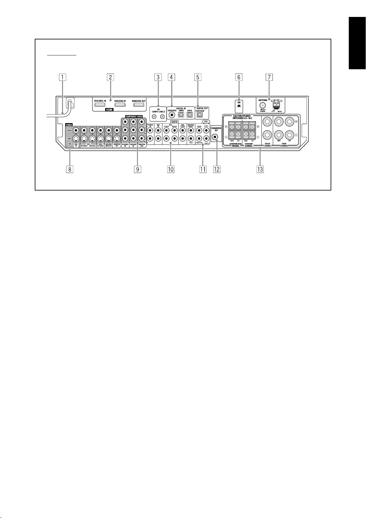
Rear Panel
Power cord (14)
1
HDMI terminals (9)
2
VCR(DBS) IN, DVR/DVD IN, MONITOR OUT
AV COMPU LINK-III terminals (45)
3
DIGITAL IN terminals (14)
4
• Coaxial: 1(DVR/DVD)
• Optical: 2(DBS)
• Optical: 3(VCR)
DIGITAL OUT terminal (14)
5
XM jack (7)
6
FM/AM ANTENNA terminals (7)
7
VIDEO jacks (10 – 13)
8
VIDEO (composite video) jacks, S-VIDEO jacks
• Input: DBS IN, VCR IN(PLAY), DVR/DVD IN(PLAY)
• Output: VCR OUT(REC), DVR OUT(REC), MONITOR OUT
COMPONENT VIDEO (Y, P
9
VCR(DBS) IN, DVR/DVD IN, MONITOR OUT
AUDIO jacks (10 – 13)
p
• Input: TV/SIRIUS IN, DBS IN, VCR IN(PLAY), DVR/DVD
IN(PLAY)
• Output: VCR OUT(REC), DVR OUT(REC)
DVD MULTI IN jacks (11)
q
CENTER, SUBWOOFER, SURR–L, SURR–R
SUBWOOFER OUT jack (8)
w
Speaker terminals (8)
e
SURROUND BACK SPEAKERS, SURROUND SPEAKERS,
CENTER SPEAKER, FRONT SPEAKERS
B, PR) jacks (10 – 13)
5
Page 8
English
Getting started
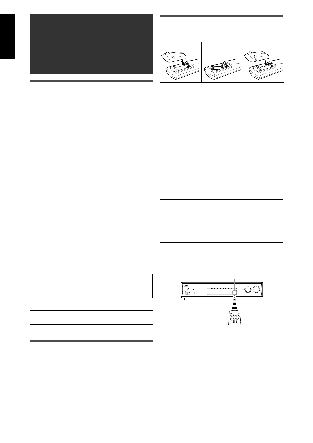
Putting the batteries in the remote
control
123
Before installation
7 General precautions
• Be sure your hands are dry.
• Turn the power off to all components.
• Read the manuals supplied with the components you are
going to connect.
7 Locations
• Install the receiver in a location that is level and protected
from moisture and dust.
• The temperature around the receiver must be between –5°C
and 35°C.
• Make sure there is good ventilation around the receiver.
Poor ventilation could cause overheating and damage the
receiver.
• Leave sufficient distance between the receiver and the TV.
7 Handling the receiver
• Do not insert any metal object into the receiver.
• Do not disassemble the receiver or remove screws, covers,
or cabinet.
• Do not expose the receiver to rain or moisture.
• Do not pull on the power cord to unplug the cord. When
unplugging the cord, always grasp the plug so as not to
damage the cord.
• When you are away on travel or otherwise for an extended
period or time, remove the plug from the wall outlet. A small
amount of power is always consumed while the power cord
is connected to the wall outlet.
Before using the remote control, put two supplied batteries
first.
1 Press and slide the battery cover on the
back of the remote control.
2 Insert the batteries.
Make sure to match the polarity: (+) to (+) and (–) to (–).
3 Replace the cover.
If the range or effectiveness of the remote control decreases,
replace the batteries. Use two R6(SUM-3)/AA(15F) type dry-cell
batteries.
• Supplied butteries are for initial setup. Replace for
continued use.
CAUTION:
Follow these precautions to avoid leaking or cracking cells:
• Place batteries in the remote control so they match the
polarity: (+) to (+) and (–) to (–).
• Use the correct type of batteries. Batteries that look similar
may differ in voltage.
• Always replace both batteries at the same time.
• Do not expose batteries to heat or flame.
When using the remote control, aim the remote control
directly at the remote sensor on the front panel.
The receiver has a built-in cooling fan which operates
while the receiver is turned on. Be sure to leave enough
ventilation to obtain sufficient cooling effect.
CAUTION:
Do not connect the AC power cord until all other connections
have been made.
Checking the supplied accessories
Check to be sure you have all of the following supplied
accessories. If anything is missing, contact your dealer
immediately.
• Remote control (× 1)
• Batteries (× 2)
• AM loop antenna (× 1)
• FM antenna (× 1)
• Dedicated earphone-type microphones (× 1)
Remote sensor
6
Page 9
English
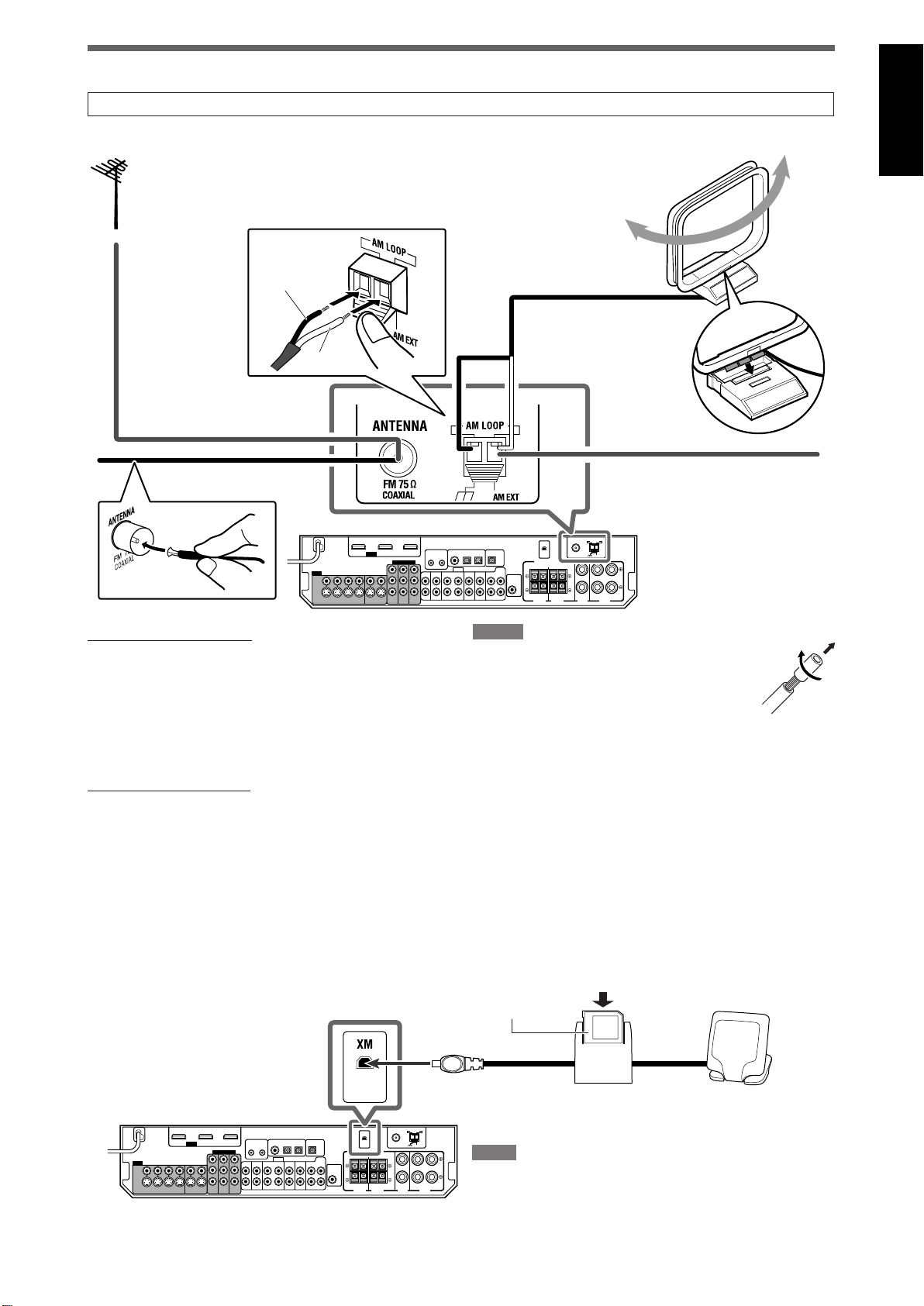
Connecting the antennas
Do not connect the AC power cord until all other connections have been made.
7 Connecting FM and AM antennas
outdoor FM antenna (not supplied).
Black
White
AM loop antenna (supplied)If FM reception is poor, connect an
Snap the tabs on the loop
into the slots of the base
to assemble the AM loop
antenna.
FM antenna (supplied)
AM antenna connection
Connect the AM loop antenna (supplied) to the AM LOOP
terminals: Connect the white cord to the AM EXT terminal, and
connect the black cord to the H terminal.
Turn the loop until you have the best reception.
• If the reception is poor, connect an outdoor single vinylcovered wire (not supplied) to the AM EXT terminal. Keep
the AM loop antenna connected.
FM antenna connection
Connect the supplied FM antenna to the FM 75 Ω COAXIAL
terminal as a temporary measure.
Extend the supplied FM antenna horizontally.
• If the reception is poor, connect an outdoor FM antenna
(not supplied). Before attaching a 75 Ω coaxial cable with a
connector, disconnect the supplied FM antenna.
If AM reception is poor, connect an
outdoor single vinyl-covered wire
(not supplied).
NOTES
• If the AM loop antenna wire is covered with vinyl,
remove the vinyl while twisting it as shown on
the right.
• Make sure the antenna conductors do not touch
any other terminals, connecting cords and power
cord. This could cause poor reception.
7 Connecting the XM Mini-Tuner System (XM Mini-Tuner and XM Mini-Tuner Home Dock)*
To enjoy XM Satellite Radio, connect the XM Mini-Tuner System (not supplied) to the receiver.
* You can also use the conventional XM Connect and Play Digital Antenna (not supplied) for the receiver.
XM Mini-Tuner (not supplied)
XM Mini-Tuner Home Dock (not supplied)
NOTE
For the best reception:
– Place the XM Mini-Tuner Home Dock antenna near a south-facing
window or where “Channel 1” can be heard clearly (see page 26).
– Make sure there is no obstruction between the XM Mini-Tuner
Home Dock antenna and the sky.
7
Page 10
English
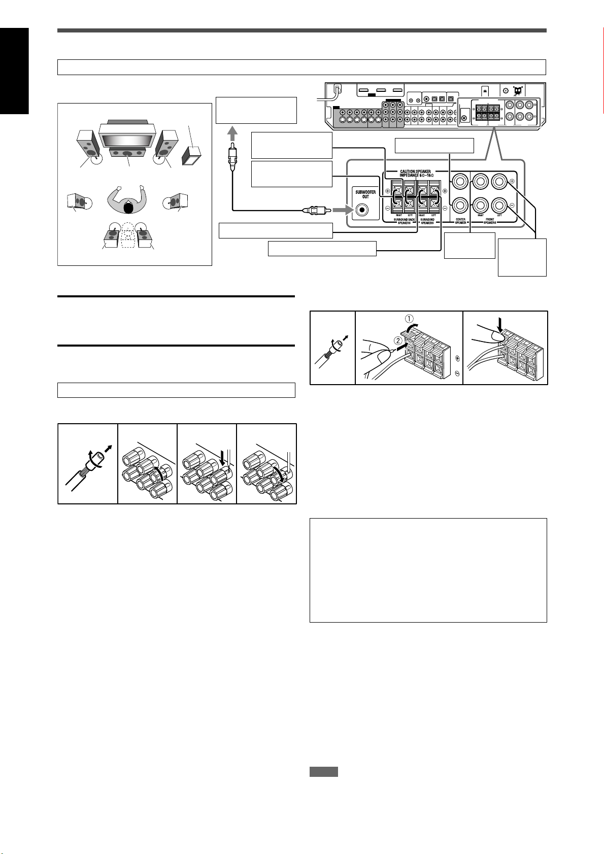
Connecting the speakers
Do not connect the AC power cord until all other connections have been made.
7 Speaker Layout Diagram
SW
Powered
subwoofer (SW)
Left surround back
speaker (SBL)*
FL
SL
CAUTIONS:
• Use speakers with the SPEAKER IMPEDANCE indicated by
the speaker terminals (6 Ω – 16 Ω).
• DO NOT connect more than one speaker to one speaker
terminal.
CFR
SR
Right surround speaker (SR)
SBRSBL (SB*)
Right surround
back speaker (SBR)
Left surround speaker (SL)
7 Connecting the speakers
Turn off all components before making connections.
To connect the center speaker and the front speakers
12 43
Center speaker (C)
Right front
speaker (R)
To connect the surround speakers and the surround back
speakers
Left front
speaker
(L)
12 3
1 Cut, twist and remove the insulation at
the end of each speaker cord.
2 Open the terminal (1), then insert the
speaker cord (2).
• For each speaker, connect the (+) and (–) terminals on
the rear panel to the (+) and (–) terminals marked on the
speakers.
1 Cut, twist and remove the insulation at
the end of each speaker cord.
2 Turn the knob counterclockwise.
3 Insert the speaker cord.
• For each speaker, connect the (+) and (–) terminals on
the rear panel to the (+) and (–) terminals marked on the
speakers.
4 Turn the knob clockwise.
3 Close the terminal.
* When using a single speaker for the surround back
speaker
You can enjoy the surround sound by one surround back
speaker. When using one surround back speaker,
– set “S BACK OUT” to “1SPK” (see page 31) and
– connect the surround back speaker to the left surround
back speaker terminal. (No sound comes from the
speaker if you connect it to the right surround back
speaker terminal.)
7 Connecting the powered subwoofer
By connecting a subwoofer, you can enhance the bass or
reproduce the original LFE signals recorded in digital software.
Connect the input jack of a powered subwoofer to the
SUBWOOFER OUT jack on the rear panel, using a cord with
RCA pin plugs (not supplied).
• Refer also to the manual supplied with your subwoofer.
After connecting all the speakers and/or subwoofer, perform
Precise Surround Setup to adjust the speaker settings
automatically (see pages 16 to 19).
NOTE
You can place a subwoofer wherever you like since bass sound is nondirectional. Normally place it in front of you.
8
Page 11
English
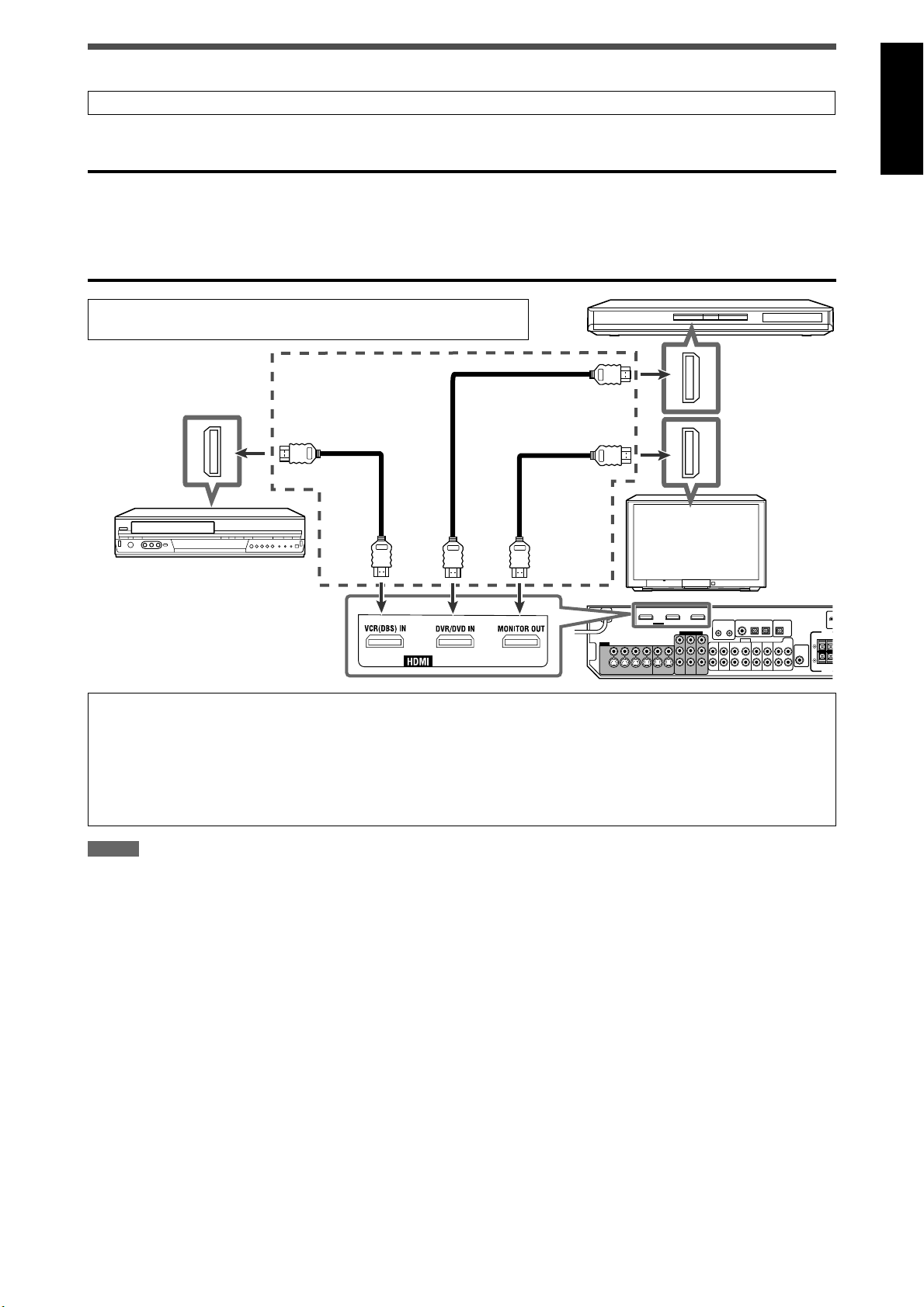
Connecting video components
Do not connect the AC power cord until all other connections have been made.
7 HDMI connection
IMPORTANT:
The HDMI video signals from the HDMI terminals are transmitted only through the HDMI MONITOR OUT terminal.
Therefore, you cannot view the playback picture on the TV:
– when the TV is connected to the receiver through the VIDEO jack (MONITOR OUT), S-VIDEO jack (MONITOR OUT), or
COMPONENT VIDEO jacks (MONITOR OUT) and
– when a playing video component is connected to the receiver through the HDMI terminal—VCR(DBS) IN or DVR/DVD IN as
well.
Turn off all components before making connections.
• When you connect the components, refer also to their manuals.
DVD recorder or
DVD player
HDMI cables
(not supplied)
TV
VCR (or DBS tuner)
Converting video signals into HDMI signals
This receiver can convert composite video, S-video, and component video signals into HDMI signals and transmit the
converted signals through the HDMI MONITOR OUT terminal. To use this function, you need to make the following procedure
beforehand:
Connect your TV and this receiver with the HDMI cable.
1
Set the video output setting (see page 34) to “HDMI.”
2
Set the video input setting (see page 21) according to the connection method for each video component.
3
NOTES
• When playing back audio and video with the HDMI connection, the HDMI lamp on the front panel is lit.
• Select “HDMI” for the audio input setting (see page 21) when you enjoy sound with the HDMI connection.
• With input video signals converted into HDMI signals, the playback picture may be distorted when you change the playback mode (fastforward, rewind, or pause, for example).
• When connecting a VCR or DBS to the HDMI VCR(DBS) IN terminal, set the HDMI select setting (see page 34) correctly according to the
equipment you connect. If you do not, you cannot view the playback picture on the TV.
• By using an HDMI-DVI conversion cable, you can connect the source components or the TV with DVI output. When connecting those
components or TV, change the audio input setting to other than “HDMI.” (See page 21.)
• This receiver is compatible with standard video formats. If non-standard video formats are coming in, the picture may not appear properly on
TV.
• The picture on the TV may not be the same aspect ratio as the ratio set on the source components.
• HDMI (High-Definition Multimedia Interface) is an interface which makes it possible to transmit digital audio and video signals with one cable.
However, when connecting a TV to this receiver with an HDMI cable, the sound coming into this receiver is not transmitted to the speakers of
the TV. You can enjoy sound only from the speakers connected to this receiver.
• When connecting a TV to the receiver with an HDMI cable, the following may cause noise or interrupt the sound and picture:
– Turning a source component on or off
– Changing the audio or video input setting of this receiver frequently
In this case, turn the receiver off, then turn it on again.
• When enjoying multi-channel PCM sound and selecting “HDMI” for the audio input setting (see page 21), some functions are not available. See
page 11 for details.
• When you enjoy HDCP contents, sound and picture may not be transmitted to the speakers and TV for a few seconds in the beginning for
confirmation.
9
Page 12
English
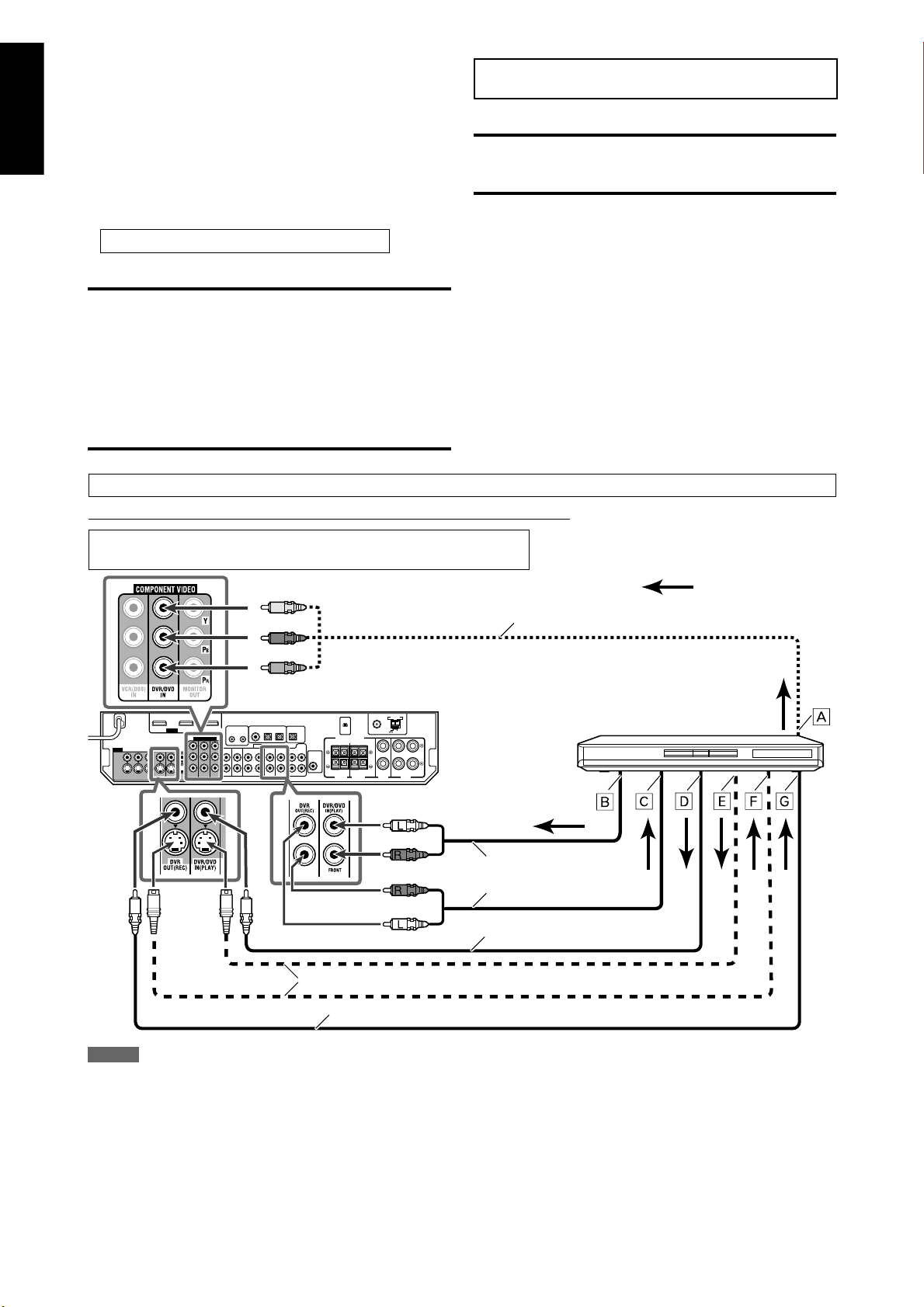
7 Audio/video connection
In addition to the HDMI terminals, this receiver is equipped
with three video terminals—composite video, S-video, and
component video terminals, and two audio jacks—analog
discrete 5.1 channel audio input jacks (DVD MULTI IN) and
stereo audio jacks.
• If your video components have S-video (Y/C-separation)
and/or component video (Y, P
using an S-video cable (not supplied) or component video
cable (not supplied). By using these terminals, you can get a
better picture quality in the order:
Component > S-video > Composite
IMPORTANT:
The video signals from one type of these input jacks are
transmitted only through the video output jacks of the
same type. Therefore, if a recording video component and
a playing video component are connected to the receiver
through the video terminals of different type, you cannot
record the picture. In addition, if the TV and a playing video
component are connected to the receiver through the video
terminals of different type, you cannot view the playback
picture on the TV.*
B, PR) jacks, connect them
Do not connect the AC power cord until all other connections have been made.
Connecting a DVD recorder or DVD player with its stereo output jacks:
DO NOT use a TV through a VCR or a TV with a built-in
VCR; otherwise, the picture may be distorted.
CAUTION:
If you connect a sound-enhancing device such as a graphic
equalizer between the source components and this receiver,
the sound output through this receiver may be distorted.
If your video components have AV COMPU LINK terminals
See also page 45 for detailed information about the
connection and the AV COMPU LINK remote control system.
* When connecting the TV to the receiver through the HDMI
MONITOR OUT terminal and selecting “HDMI” for the video
output setting, you can view the playback picture on the TV.
Turn off all components before making connections.
• When you connect the components, refer also to their manuals.
Green
Blue
Red
White
Red
Red
White
S-video cable (not supplied)
: signal flow
Component video cable (not supplied)
DVD recorder or DVD player
Stereo audio cable
(not supplied)
Composite video cable
(not supplied)
Composite video cable (not supplied)
NOTES
• Select the audio and video input setting according to the
connection method. See page 21 for details.
• You can enjoy digital sound if using a digital coaxial or optical
cable. When shipped from the factory, the digital coaxial terminal—
DIGITAL IN 1(DVR/DVD) on the rear of the receiver is set for a DVD
recorder and DVD player. For details of digital audio connection, see
page 14.
10
To component video output
Å
• Connect Y, P
To left/right audio channel output
ı
Only for DVD recorder: To left/right audio channel input
Ç
To composite video output
Î
To S-video output
‰
Only for DVD recorder: To S-video input
Ï
Only for DVD recorder: To composite video input
Ì
B, and PR correctly.
Page 13
English
Do not connect the AC power cord until all other connections have been made.
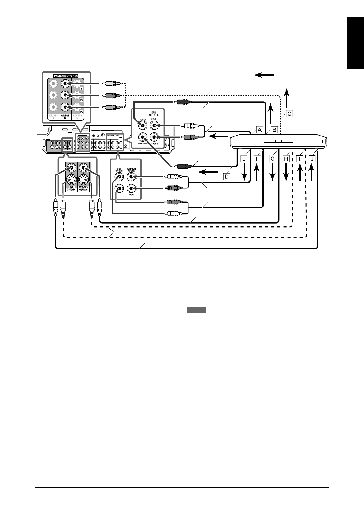
Connecting a DVD recorder or DVD player with its analog discrete output jacks (DVD MULTI IN):
If your DVD recorder or DVD player has analog 5.1 channel output jacks, use the connection below. When a DVD-Audio disc is
played back, the original high-quality multi-channel sounds can be reproduced by using this connection.
Turn off all components before making connections.
• When you connect the components, refer also to their manuals.
Green
Blue
Red
Component video cable (not supplied)
Monaural audio cable (not supplied)
White
Stereo audio cable
(not supplied)
Red
Monaural audio cable
(not supplied)
White
Red
Stereo audio cable
Red
(not supplied)
: signal flow
DVD recorder or
DVD player
S-video cable (not supplied)
Composite video cable (not supplied)
To left/right surround channel audio output
Å
To center channel audio output
ı
To component video output
Ç
• Connect Y, P
To subwoofer output
Î
To left/right front channel audio output
‰
B, and PR correctly.
When you enjoy the sound recorded in DVD-Audio...
You can enjoy the sound recorded in DVD-Audio with either
analog or digital methods.
– With analog method:
1. Connect your DVD recorder or DVD player to this
receiver according to the diagram above.
2. Select “A MULTI” for the audio input setting. (See page
21.)
– With digital method:
1. Connect your DVD recorder or DVD player and TV to this
receiver with the HDMI cables. (See page 9.)
2. Select “HDMI” for the audio input setting. (See page 21.)
White
Composite video cable
(not supplied)
Only for DVD recorder: To left/right front channel audio
Ï
input
To composite video output
Ì
To S-video output
Ó
Only for DVD recorder: To S-video input
È
Only for DVD recorder: To composite video input
Ô
NOTES
• When selecting “A MULTI” for the audio input setting and using
the headphones, you can listen to the front channel sounds (left
and right) only. The 3D HEADPHONE mode (see page 42) is not
available.
• When selecting “A MULTI” for the audio input setting or when
multi-channel PCM signals (see page 41) are coming in with
selecting “HDMI” for the audio input setting, the following items
are not available:
– Precise Surround Setup (see pages 16 to 19)
– Decode mode (see page 22)
– CC Converter (see page 23)
– EX/ES/PLllx (see page 32)
– Dual Mono (see page 32)
– Subwoofer output (see page 33)
– Crossover frequency (see page 33)
– Low frequency effect attenuator (see page 33)
– Midnight mode (see page 33)
– Digital equalization patterns (see page 36)
– Bass Boost (see page 37)
– Input attenuator mode (see page 37)
– Sound parameters for Surround/DSP modes (see pages 37 and
38)
– Surround/DSP mode selection (see page 44)
• The audio delay level setting (see page 34) does not take effect
when selecting “A MULTI” for the audio input setting.
• When you enjoy the sound recorded in DVD-Audio through the
HDMI connection, use a DVD recorder or DVD player compatible
with HDMI version 1.1.
11
Page 14

English
Do not connect the AC power cord until all other connections have been made.
Turn off all components before making connections.
• When you connect the components, refer also to their manuals.
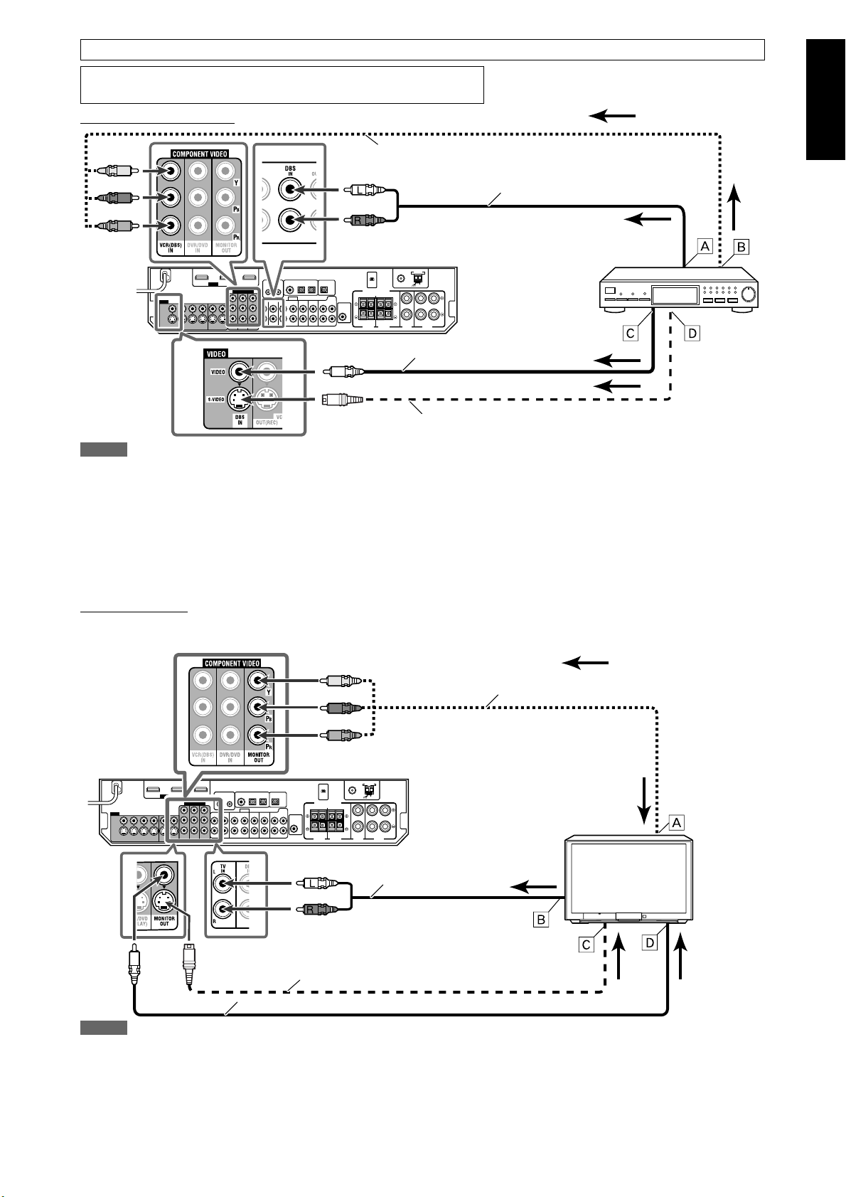
Connecting a VCR:
Green
Blue
Component video cable (not supplied)
Red
White
Red
Red
White
S-video cable (not supplied)
: signal flow
VCR
Stereo audio cable
(not supplied)
Composite video cable
(not supplied)
Composite video cable (not supplied)
NOTES
• Select the audio and video input settings according to the connection method. See page 21 for
details.
• When connecting a VCR to the COMPONENT VIDEO jacks, select “VCR” for the COMPONENT
select setting (see page 34); otherwise, the following occurs:
– You cannot view the playback picture on the TV.
– The AV COMPU LINK remote control system (see pages 45 and 46) cannot operate properly.
• You can enjoy digital audio if using a digital coaxial or optical cable. When shipped from the
factory, the digital optical terminal—DIGITAL IN 3(VCR) on the rear of the receiver is set for a
VCR. For details of the digital audio connection, see page 14.
Connecting a SIRIUS Satellite Radio
White
Red
Stereo audio cable (not supplied) SIRIUS Satellite Radio
To component video output
Å
• Connect Y, P
To left/right audio channel output
ı
To left/right audio channel input
Ç
To composite video output
Î
To S-video output
‰
To S-video input
Ï
To composite video input
Ì
B, and PR correctly.
NOTES
• To connect KT-SR2000 (JVC SIRIUS Satellite Radio) to this receiver, it is required to separately purchase KS-K6013 Home Docking Kit.
• You cannot use a digital audio cable (coaxial or optical) to connect a SIRIUS Satellite Radio to this receiver.
• After connecting a SIRIUS Satellite Radio to the TV/SIRIUS IN jacks, change the source name to “SIRIUS.” See page 20 for details.
12
Page 15
English
Do not connect the AC power cord until all other connections have been made.
Turn off all components before making connections.
• When you connect the components, refer also to their manuals.
Connecting a DBS tuner:
: signal flow
Green
Blue
Red
Component video cable (not supplied)
White
Stereo audio cable (not supplied)
Red
Composite video cable
(not supplied)
S-video cable (not supplied)
NOTES
• Select the audio and video input setting according to the connection method. See page 21 for
details.
• When connecting a DBS tuner to the COMPONENT VIDEO jacks, select “DBS” for the COMPONENT
select setting (see page 34); otherwise, you cannot view the playback picture on the TV.
• You can enjoy digital sound if using a digital coaxial or optical cable. When shipped from the
factory, the digital optical terminal—DIGITAL IN 2(DBS) on the rear of the receiver is set for a DBS
tuner. For details of digital audio connection, see page 14.
DBS tuner
To left/right audio channel
Å
output
To component video output
ı
• Connect Y, P
B, and PR
correctly.
To composite video output
Ç
To S-video output
Î
Connecting a TV:
Connect the TV to the appropriate MONITOR OUT jacks to view the playback picture from any other connected video
components.
Green
Component video cable (not supplied)
Blue
Red
White
Stereo audio cable
(not supplied)
Red
S-video cable (not supplied)
Composite video cable (not supplied)
NOTES
• Select the audio input setting according to the connection method. See page 21 for
details.
• You can enjoy digital sound if using a digital coaxial or optical cable. For details of the
digital audio connection, see page 14.
• Select “OTHER” for the video output setting (see page 34).
To component video input
Å
• Connect Y, P
To left/right audio channel output
ı
To S-video input
Ç
To composite video input
Î
: signal flow
TV
B, and PR correctly.
13
Page 16
English
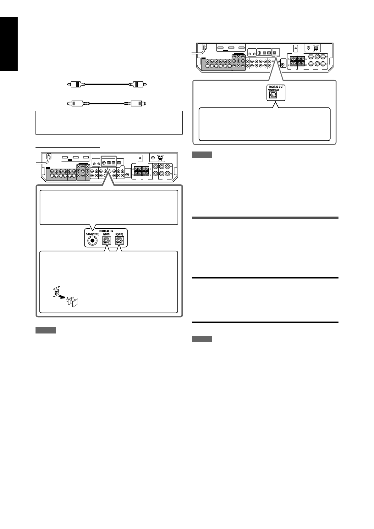
7 Digital audio connection
This receiver is equipped with three DIGITAL IN terminals—
one digital coaxial terminal and two digital optical terminals—
and one DIGITAL OUT terminal.
To reproduce the digital sound, use the digital audio
connection in addition to the analog audio connection
methods described on pages 10 to 13.
Digital coaxial cable (not supplied)
Digital optical cable (not supplied)
Digital output terminal:
You can connect any digital components which have an
optical digital input terminal.
Turn off all components before making connections.
• When you connect the components, refer also to their
manuals.
Digital input terminals:
When the component has a digital coaxial output
terminal, connect it to the 1(DVR/DVD) terminal, using a
digital coaxial cable (not supplied).
When the component has a digital optical output
terminal, connect it to the 2(DBS) or 3(VCR) terminal,
using a digital optical cable (not supplied).
Before connecting a digital optical
cable, unplug the protective plug.
Connecting digital recording equipment to the
DIGITAL OUT terminal enables you to perform
digital-to-digital recording.
NOTES
• The digital signal format transmitted through the DIGITAL OUT
terminal is the same as that of the input signal. For example, when
the DTS signals are input, the DTS signals are transmitted.
• The digital signal coming through the USB terminal, HDMI input
terminal and XM jack cannot be output from the DIGITAL OUT
terminal.
Connecting the power cord
When all the audio/video connections have been made,
connect the AC power plug to the wall outlet. Make sure that
the plugs are inserted firmly.
• The standby lamp lights in red.
CAUTIONS:
• Do not touch the power cord with wet hands.
• Do not alter, twist or pull the power cord, or put anything
heavy on it, which may cause fire, electric shock, or other
accidents.
• If the cord is damaged, consult a dealer and have the power
cord replaced with a new one.
NOTES
• When shipped from the factory, the DIGITAL IN terminals have been
set for use with the following components:
– 1(DVR/DVD): For DVD recorder or DVD player
– 2(DBS): For DBS tuner
– 3(VCR): For VCR
If you connect the components, change the digital input (DIGITAL
IN) terminal setting correctly. See “Setting the digital input (DIGITAL
IN) terminals—DIGITAL IN 1/2/3” on page 34.
• Select “DIGITAL” for the audio input setting (see page 21).
NOTES
• Keep the power cord away from the connecting cables and the
antennas. The power cord may cause noise or screen interference.
• The preset settings such as preset channels and sound adjustment
may be erased in a few days in the following cases:
– When you unplug the power cord.
– When a power failure occurs.
• When you unplug the power cord with the receiver on and connect
the power cord again, the receiver enters standby mode.
14
Page 17
English
USB connection
This receiver is equipped with a USB terminal on the front
panel. You can connect your PC to this terminal and enjoy
sound reproduced through your PC.
When you connect your PC for the first time, follow the
procedure below.
• Remember you cannot send any signal or data to your PC
from this receiver.
IMPORTANT:
Check if your PC equipped with the CD-ROM drive is running
on Windows® 98 SE*, Windows® Me*, Windows® 2000*, or
Windows® XP* and prepare its CD-ROM.
7 How to install the USB drivers
The following procedure is described using the English
version of Windows® XP*. If your PC is running on a different
version or language of operating system, the windows shown
on your PC monitor will differ from the ones used in the
following procedure.
See pages 20 and 21 for the operations of the receiver.
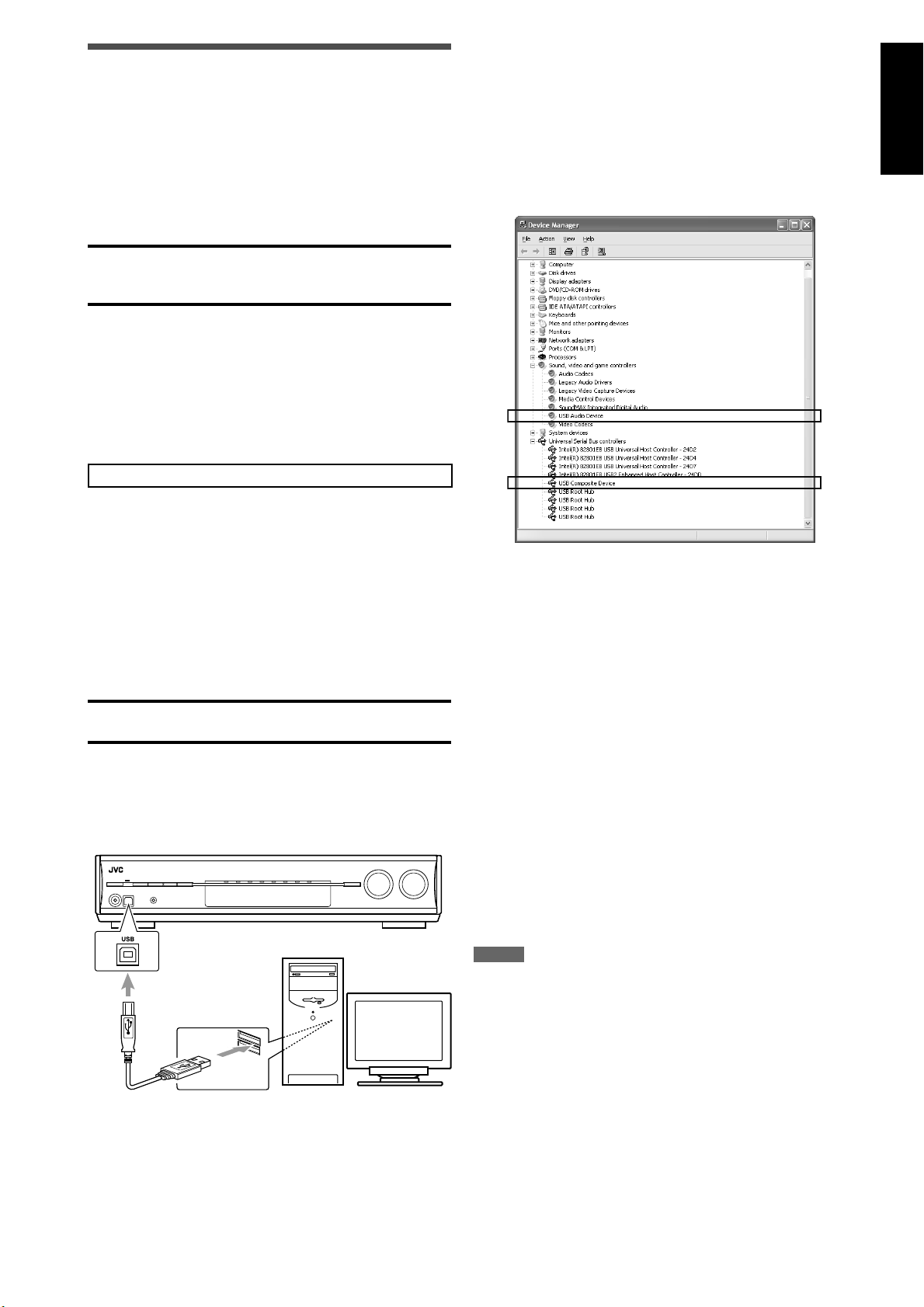
5 Check if the drivers are correctly
installed.
1. Open the Control Panel on your PC:
Select [Start] = [Control Panel].
2. Select [System] = [Hardware] = [Device Manager] =
[Sound, video and game controllers] and [Universal
Serial Bus controllers].
• The following window appears, and you can check if the
drivers are installed.
1 Turn on your PC.
• If the PC has been turned on, quit all the applications
now running.
2 Turn on the receiver, and select the
source as “USB.”
3 Set the volume to minimum.
IMPORTANT:
Always set the volume to “0” when connecting or
disconnecting the other equipment.
4 Connect the receiver to the PC using a
USB cable (not supplied).
• Use “USB series A plug to B plug” cable when
connecting.
PC
USB cable
(not supplied)
The USB drivers are installed automatically.
• If the USB drivers are not installed automatically, install
the USB drivers by following the instructions on the PC
monitor.
Now your PC is ready for playback through the USB
connection.
After installation is completed, you can use your PC as the
playback source. The PC automatically recognizes the receiver
whenever the receiver is connected by a USB cable and turned
on.
• When not using the PC as the playback source, disconnect
the USB cable from the receiver.
To play back sounds on the PC, refer to the manual supplied
with the sound reproduction application installed in the PC.
If no sound comes from the speakers, check the following:
– Select “USB” as the source.
– Connect the USB cable correctly.
– Check the receiver is recognized by the PC properly (see
above).
– Check the playback software is compatible with the PC.
– Open the Control Panel on your PC, select [Sounds and
Audio Devices] = [Audio] tab = [Sound playback] =
[Default device], and check [Default device] is set to [USB
Audio DAC].
NOTES
• DO NOT turn off the receiver or disconnect the USB cable while
installing the drivers and while your PC is recognizing the receiver.
• Use a USB cable (version 1.1 or later). Recommended cord length is
less than 1.5 m.
• If your PC does not recognize the receiver, disconnect the USB cable
and connect it again. If it does not work yet, restart Windows®*.
• The installed drivers can be recognized only when the USB cable is
connected between the receiver and your PC.
• The sound may not be played back correctly—interrupted or
degraded—due to your PC settings and PC specifications.
* Microsoft®, Windows® 98 SE, Windows® Me, Windows® 2000,
and Windows® XP are registered trademarks of Microsoft
corporation.
15
Page 18
English
Precise Surround
Setup
By using Precise Surround Setup, you can optimize the
speaker settings easily, quickly and systematically without
troublesome adjustments.
To obtain the best possible sound effect from the Surround/
DSP modes, set up the speaker and subwoofer information
after all the connections are completed.
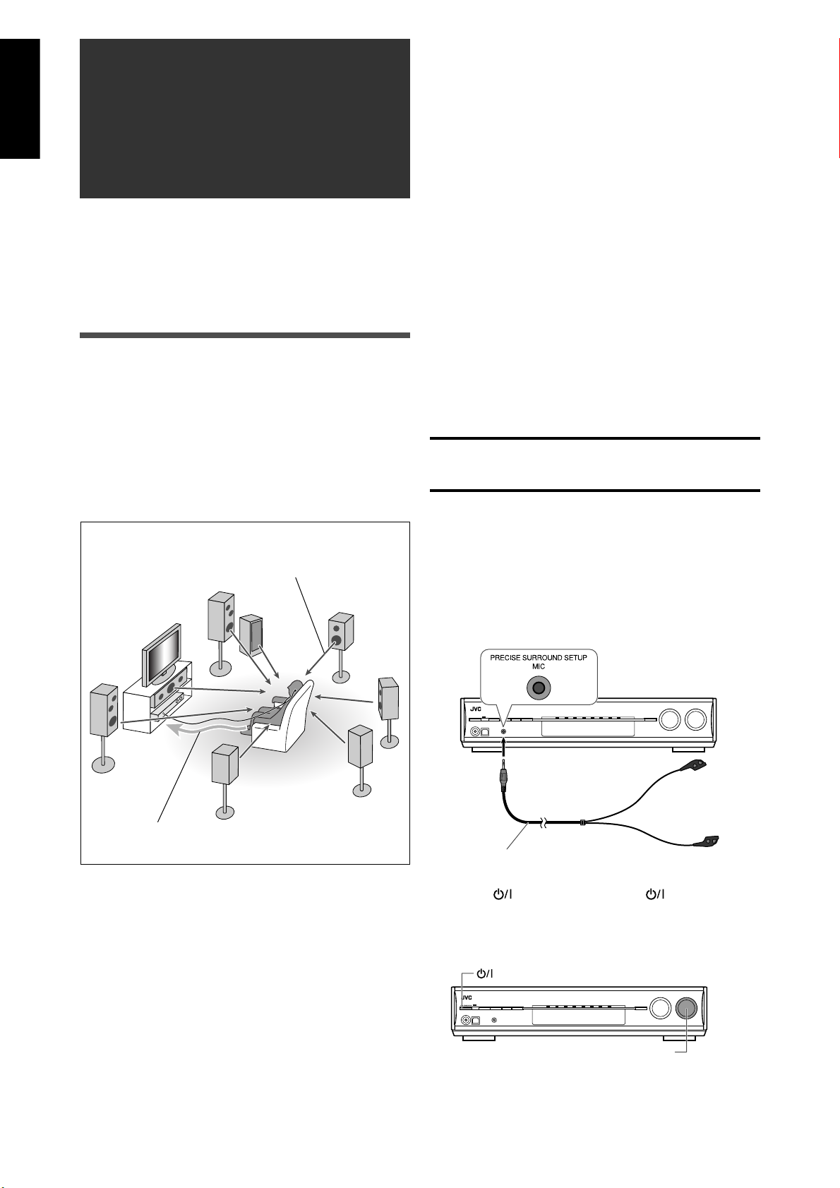
Setting the speakers automatically
Precise Surround Setup detects the sound from the speakers
to measure your listening environment with dedicated
earphone-type microphones (supplied), and automatically
adjusts the following in less than 1 minute:
• Speaker size*
• Speaker distance*
• Speaker output level*
• Crossover frequency*
• Frequency response
The receiver generates test tones from each
speaker and picks them up with dedicated
earphone-type microphones.
7 Before starting Precise Surround Setup
• Connect all of your speakers and subwoofer correctly and
confirm their position.
• When subwoofer has a built-in volume and crossover
frequency controls, adjust them as follows:
– Set the volume level to the medium.
– Set the crossover frequency to the highest level.
• Precise Surround Setup is not available in the following
cases:
– While headphones are connected
– When selecting “A MULTI” for the audio input setting (see
page 11)
– When multi-channel PCM signals (see page 41) are coming
in with selecting “HDMI” for the audio input setting (see
page 11)
• Do not block between the earphone-type microphones and
speakers while the microphones are picking up test tones
from the speakers.
• If the microphone cord is not long enough to make a
connection between the receiver and your listening
position, use a stereo extension cord (not supplied).
– You cannot get correct results with a monaural extension
cord.
CAUTION:
Be sure that loud test tones will be generated from
speakers during Precise Surround Setup.
• The volume of test tones is not adjustable.
7 Operating procedure
Plug the dedicated earphone-type
1
microphones into the PRECISE
SURROUND SETUP MIC jack.
• Keep the connection until Precise Surround Setup is
completed.
The microphones feedback the test
tones to the receiver.
* You can also adjust the settings manually. (See pages 29 to
31, and 33.)
16
Dedicated earphone-type microphones (supplied)
2 Press STANDBY/ON (or AUDIO on
the remote control) to turn the power on.
• Set the volume level to the medium or lower turning the
MASTER VOLUME control (see page 21).
STANDBY/ON button
MASTER VOLUME control
Page 19
English
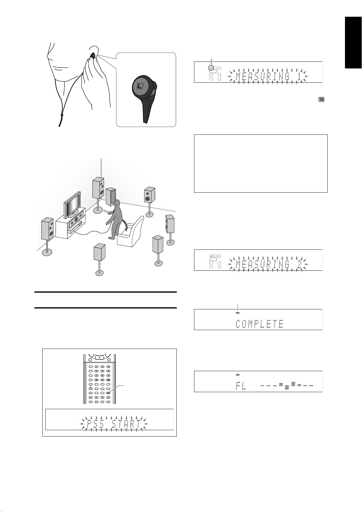
3 Put on the microphones.
• Insert the microphone with “L” into your left ear, the
microphone with “R” your right ear.
Example:
Microphone with “L”
Precise Surround Setup starts detecting the speaker and
subwoofer information.
• When starting Precise Surround Setup, the muting mode
and Dimmer are automatically canceled.
• “MEASURING 1” flashes on the display.
Current speaker*
1
*
When the current speaker is the right or left surround
back speaker, two surround back speaker indicators (
light up at a time.
A test tone comes out of each speaker in the following
order, then the microphones pick up the test tones and
feedback it to the receiver:
1
)
4 Take your usual listening position with
the microphones and the remote control.
CAUTION:
Keep quiet so that Precise Surround Setup can detect test
tones properly.
FL (Left front speaker) = C (Center speaker) = FR
(Right front speaker) = SR (Right surround speaker)
= SBR (Right surround back speaker)*
surround back speaker)*
= SW (Subwoofer)
2
*
When using a single speaker for the surround back
speaker, the test tone comes out of “SB (Surround
back speaker)” instead of “SBR” and “SBL.”
• Do not touch the microphones while the microphones
are picking up the test tones.
The receiver generates test tones again.
Precise Surround Setup starts detecting, adjusts the
sound output level from each speaker, and corrects the
frequency response of each speaker.
• “MEASURING 2” flashes on the display.
When Precise Surround Setup is completed, “COMPLETE”
appears and the PSS indicator lights up on the display.
PSS indicator
2
= SL (Left surround speaker)
‘
‘
2
= SBL (Left
5 Press and hold PSS on the remote control
for about 4 seconds until “PSS START”
starts flashing on the display.
PSS
• If Precise Surround Setup is not completed
properly...
An error message will appear on the display.
In such a case, see “Troubleshooting for Precise
Surround Setup“ on page 19.
‘
An optimized test tone comes out of each speaker so that
you can confirm the results of Precise Surround Setup, and
the corrected frequency response of each speaker appears
on the display at the same time.
• See “Checking the frequency responses corrected
by Precise Surround Setup” on page 18 about the
frequency responses on the display.
‘
The receiver automatically returns to the normal operation
mode after all the test tones have been output from the
speakers.
Continued on the next page
17
Page 20
English
6 Unplug the earphone-type microphones.
• When unplugging the microphones, pull on the plug,
not the cord itself.
NOTES
• Do not press any buttons on the remote control or the front panel
of the receiver during Precise Surround Setup; otherwise, the
receiver stops setting and returns to the normal operation mode.
– After “COMPLETE” is displayed, the Precise Surround Setup results
are applied to the speaker settings.
• The speaker size measured by Precise Surround Setup may be
different from that of the manual setting recommendation (see
page 30). Precise Surround Setup measures the speaker size not
only by the cone speaker size but also by the other speaker features.
• There may be a case that the receiver fails to detect subwoofer
and does not activate it (no optimized test tone comes out of the
subwoofer).
In such a case, set the volume level of the subwoofer higher and
perform Precise Surround Setup again.
• When you change your listening environment, such as speakers,
speaker position, your listening position or so, perform Precise
Surround Setup again to optimize the speaker settings.
• Depending on the listening environment, Precise Surround Setup
may not measure the speaker settings accurately. In such a case,
adjust the settings manually. See pages 29 to 31, and 33.
• The supplied earphone-type microphones cannot be used as
headphones.
• When the AV COMPU LINK remote control system works during
Precise Surround Setup, this receiver stops setting and returns to
the normal operation mode.
7 Turning the frequency optimizing function
off
After performing Precise Surround Setup, the receiver
optimizes the frequency response for each speaker.
You can turn the frequency optimizing function off.
Press PSS to turn the frequency optimizing
function off.
• Each time you press the button, the frequency optimizing
function alternates between on and off.
When the function is activated, the PSS indicator is lit.
NOTE
This function is not available:
– Until Precise Surround Setup has been completed at least once;
otherwise, “NO PSS” appears on the display.
– When selecting “A MULTI” for the audio input setting (see page 11).
– When multi-channel PCM signals (see page 41) are coming in with
selecting “HDMI” for the audio input setting (see page 11).
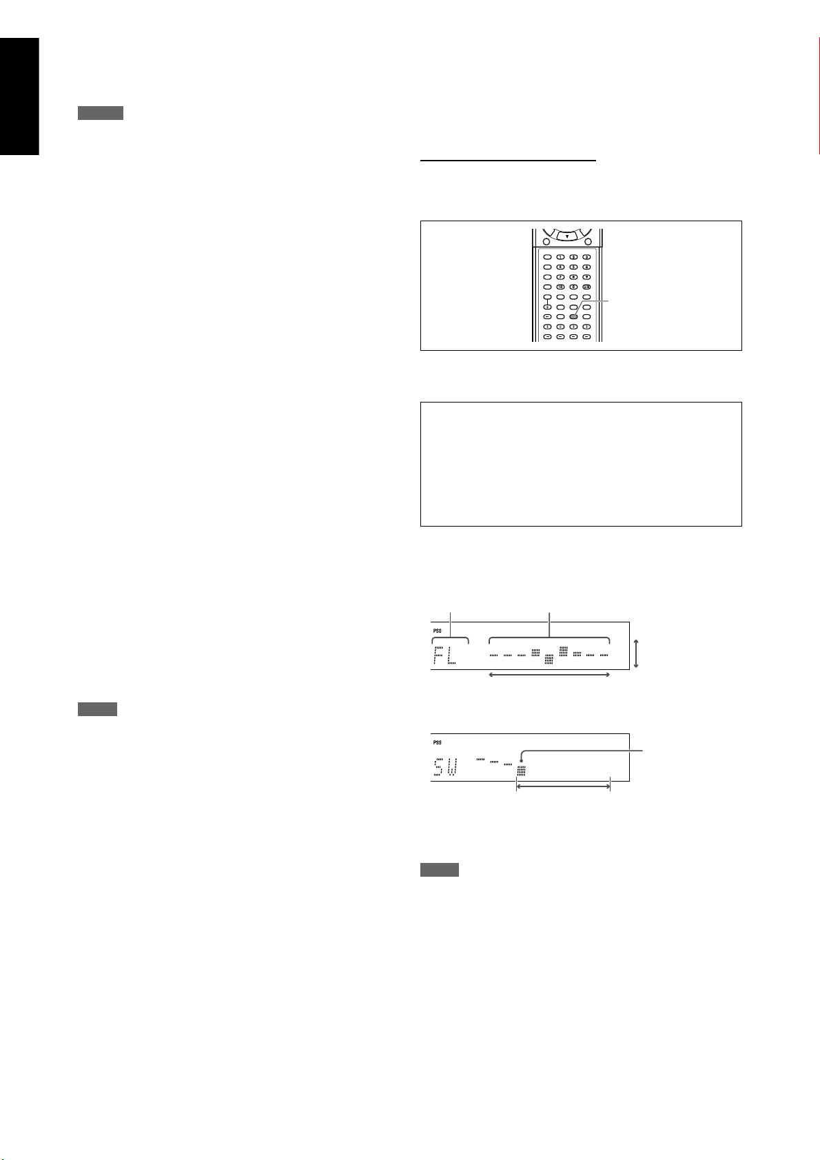
7 Checking the frequency responses corrected
by Precise Surround Setup
You can check the current settings of the frequency responses
with test tones from speakers and the indications on the
display when the frequency optimizing function is activated.
From the remote control ONLY:
1 Press TEST to check the frequency
response of each speaker on the display.
TEST
• A test tone also comes from each speaker in the following
order:
FL (Left front speaker) = C (Center speaker) = FR (Right
front speaker) = SR (Right surround speaker) = SBR
(Right surround back speaker)* = SBL (Left surround back
speaker)* = SL (Left surround speaker) = SW (Subwoofer)
* When using a single speaker for the surround back
speaker, the test tone comes out of “SB (Surround back
speaker)” instead of “SBR” and “SBL.”
• The frequency response of each speaker appears on the
display as follows:
EX. 1: When a test tone comes from the left front speaker
Current speaker Frequency response
+9 dB
Optimizing level
–9 dB
Low HighFrequency
EX. 2: When a test tone comes from the subwoofer
Crossover
frequency
80 Hz 200 Hz
2 Press TEST again to stop the test tone.
NOTE
While the PSS indicator is off, pressing TEST generates test tones
without showing frequency responses. See page 36.
18
Page 21
English
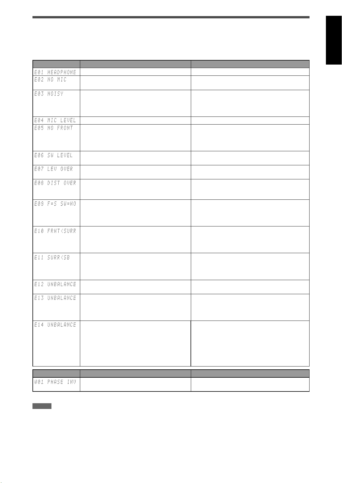
Troubleshooting for Precise Surround Setup
When problems occur, a message appears on the display during Precise Surround Setup. In this case, refer to the following
solution, then perform Precise Surround Setup again.
• To restart Precise Surround Setup, press PSS on the remote control; however, when you have turned the receiver off for the
solution, start from step
Error message Possible cause Solution
*
2 again.
Headphones are connected to the PHONES jack. Unplug the headphones.
The dedicated earphone-type microphones are
not connected correctly.
There is some background noise. • Restart in a quiet environment.
The speaker is too close to the listening position. Place the speakers farther from the listening position.
• Any of the front speakers is not connected or its
connection is loose.
• The microphone connection is loose.
The built-in volume control of the powered
subwoofer is set to too high.
*
The speaker is too far from the listening position
or the speaker angle is inappropriate.
*
The speaker is too far from the listening position. The speaker distance is adjustable up to 9 m (30 ft).
*
• When the size of the front speakers is small, no
subwoofer is detected.
• The receiver might have failed to detect
subwoofer.
The front speakers are smaller than the surround
*
speakers.
The surround speakers are smaller than the
surround back speakers.
The right-and-left front speaker size is
*
unproportioned.
*
• Any of the surround speakers is not connected
or its connection is loose.
• The right-and-left surround speaker size is
unproportioned.
*
• The left surround back speaker is not connected
or its connection is loose even though the right
surround back speaker is detected.
• The right-and-left surround back speaker size is
unproportioned.
Plug the microphones into the PRECISE SURROUND
SETUP MIC jack on the front panel firmly.
• If some electronic equipment is used near the
listening position, turn off the equipment such as
air conditioners, etc.
• Check the left and right front speakers connections.
• Plug the microphones into the PRECISE SURROUND
SETUP MIC jack on the front panel firmly.
Set the volume level of the subwoofer lower.
Adjust the speaker position and angle.
Place the speaker within the adjustable range from
the listening position.
• Check the connection of the subwoofer and turn it
on, or replace the front speakers with larger ones.
• Set the volume level of the subwoofer higher.
• Change the front speakers with the larger ones
than the surround speakers.
• Change the surround speakers with the smaller
ones than the front speakers.
• Change the surround speakers with the larger ones
than the surround back speakers.
• Change the surround back speakers with the
smaller ones than the surround speakers.
Rearrange the front speakers as their size is
proportioned.
• Check the connection of the surround speakers.
• Rearrange the surround speakers as their size is
proportioned.
• Check the connection of the left surround back
speaker.
• When using a single speaker as the surround
back speaker, connect it to the left surround back
speaker terminal (see page 8).
• Rearrange the surround back speakers as their size
is proportioned.
Warning message Possible cause Solution
The polarity of the speaker connection is wrong. Match the polarity of the speaker terminals (see page
*
8).
* The signal indicator of the corresponding speaker lights up with the error/warning message.
NOTES
• Before making speaker connections, turn the receiver off and unplug the power cord.
• If you press the source selecting button for the current source on the remote control while an error message is displayed, the receiver cancels
Precise Surround Setup and returns to the normal operation mode.
• If multiple errors are detected during Precise Surround Setup, only the most serious error will be shown on the display.
• The warning message is displayed for about 10 seconds and the receiver automatically returns to Precise Surround Setup.
• Depending on the speaker performance or the listening position, there may be a case that the warning message appears even though speaker
connections are correct. In such a case, there is no effect on the results of Precise Surround Setup.
19
Page 22
English
Basic operations
132
Source lamps
1
2
3
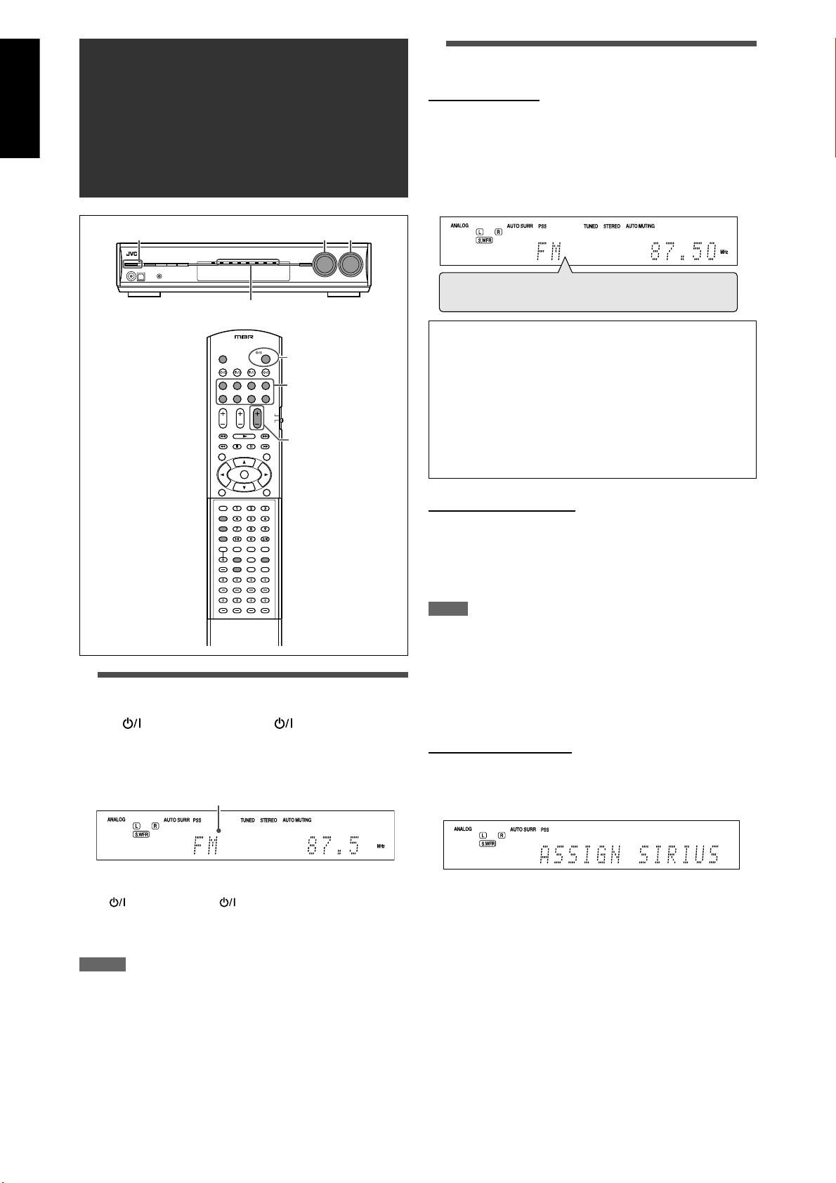
2 Select the source to play
On the front panel:
Turn SOURCE SELECTOR until the source
name you want appears on the display.
The source lamp corresponding to the selected source lights
in red.
• As you turn SOURCE SELECTOR, the source changes as
follows:
DVR/DVD Ô VCR Ô DBS Ô TV(SIRIUS)* Ô USB Ô
XM Ô FM Ô AM Ô (Back to the beginning)
DVR/DVD: Select this for the DVD recorder or DVD player.
VCR: Select this for the VCR.
DBS: Select this for the DBS tuner.
TV*: Select this for the TV.
SIRIUS*: Select this for the SIRIUS Satellite Radio.
USB: Select this for the PC component.
XM: Select this for the XM Satellite Radio.
FM: Select this for the FM broadcast.
AM: Select this for the AM broadcast.
1 Turn on the power
Press STANDBY/ON (or AUDIO on the
remote control).
The standby lamp goes off and the current source lamp lights
in red.
Current source name appears.
To turn off the power (into standby):
Press STANDBY/ON (or AUDIO on the remote control)
again.
The standby lamp lights in red.
From the remote control:
Press one of the source selecting buttons.
• For “FM” and “AM,” press FM/AM.
Each time you press the button, the band alternates
between “FM” and “AM.”
NOTE
When you connect a VCR or DBS to the HDMI VCR(DBS) IN terminal
or COMPONENT VIDEO jacks on the rear of the receiver, you need
to select either “VCR” or “DBS” for each terminal according to the
component you connect (see page 34).
* Changing the source name of TV/SIRIUS input
On the front panel ONLY:
Press SET when “TV” is selected as the
source.
• “ASSIGN SIRIUS” appears on the display for a while.
• To change the source name to “TV,” press SET when “SIRIUS”
is selected as the source. “ASSIGN TV” appears on the display
for a while.
NOTES
• A small amount of power is consumed in standby mode. To turn the
power off completely, unplug the AC power cord.
• Turning a source component on before turning the receiver on
may cause a noise or interrupt the sound and picture. In this case,
turn both the source component and the receiver off, then turn the
receiver on before turning the source component on.
20
Page 23
English
3 Adjust the volume
To increase the volume, turn MASTER
VOLUME control clockwise (or press
VOLUME + on the remote control).
7 Selecting the video input setting
From the remote control ONLY:
1 Press one of the source selecting buttons
to select the source you want.
To decrease the volume, turn MASTER
VOLUME control counterclockwise (or press
VOLUME – on the remote control).
• When you adjust the volume, the volume level indication
appears on the display for a while.
CAUTION:
Always set the volume to the minimum before starting any
sources. If the volume is set at its high level, the sudden blast
of sound energy can permanently damage your hearing and/
or ruin your speakers.
NOTE
The volume level can be adjusted within the range between “0”
(minimum) and “50” (maximum).
7 Listening with headphones
You can enjoy not only stereo software but also multi-channel
software through the headphones. (Sounds are down-mixed
to the front channels while playing multi-channel software.)
Connect a pair of headphones to the
PHONES jack on the front panel to activate
the HEADPHONE mode.
The HEADPHONE indicator lights up on the display.
• You can also enjoy the Surround/DSP mode through the
headphones—3D HEADPHONE mode (see page 42).
• Disconnecting a pair of headphones from the PHONES jack
cancels the HEADPHONE (or 3D HEADPHONE) mode and
activates the speakers.
CAUTIONS:
• Be sure to turn down the volume:
– Before connecting or putting on headphones, as high
volume can damage both the headphones and your
hearing.
– Before removing headphones, as high volume may output
from the speakers.
• Do not plug headphones into the PRECISE SURROUND
SETUP MIC jack; otherwise, loud tones may come out of the
headphones.
NOTES
• When using the headphones, the speaker settings does not take
effect temporarily.
• The supplied earphone-type microphones cannot be used as
headphones.
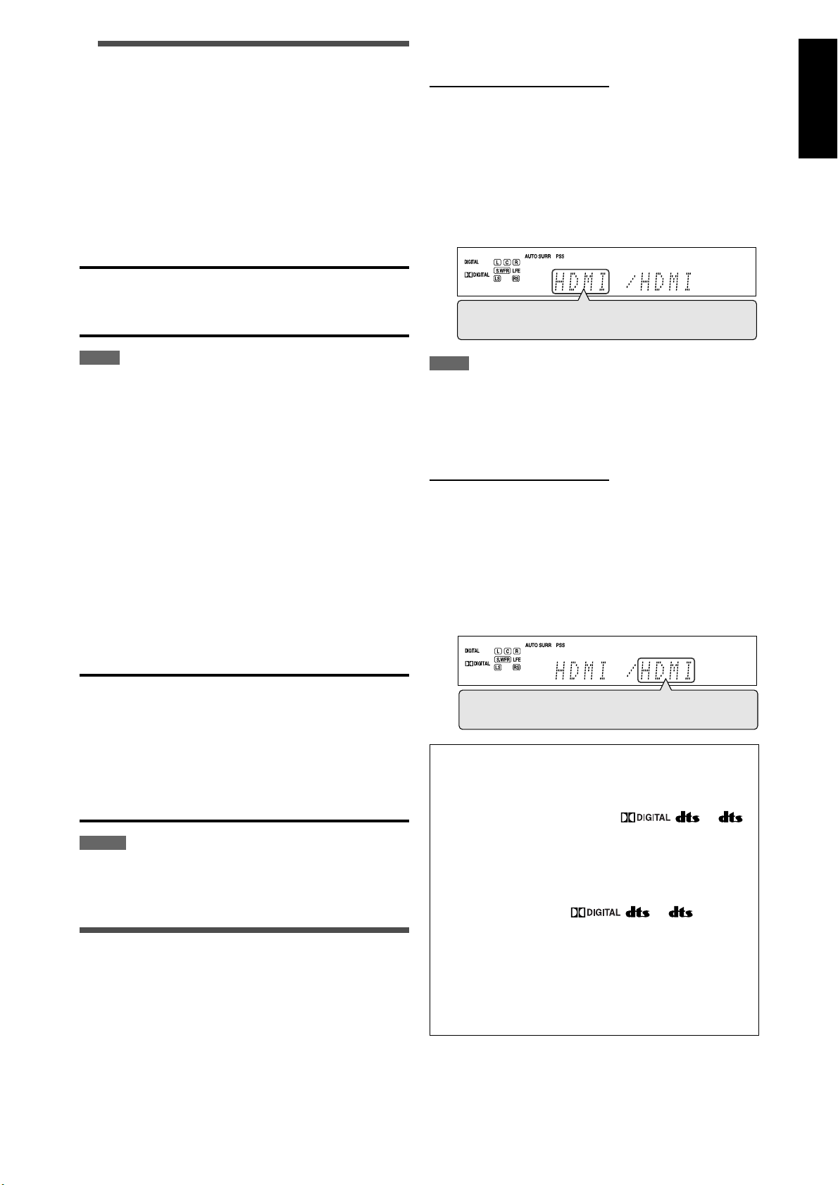
Selecting the video and audio input
settings
You need to select the proper video and audio input settings
for each source according to the connection methods on
pages 9 to 14.
• In case of digital audio connection using the DIGITAL IN
terminals on the rear of the receiver, you also need to select
the correct digital input terminal (see page 34).
• Once you have made an adjustment, it is memorized for
each source.
2 Press VIDEO INPUT to select the video
input setting.
• Each time you press the button, the input setting
changes as follows. This setting is memorized for each
source.
HDMI = CMPNT (Component) = S (S-Video) =
C (Composite) = (Back to the beginning)
NOTE
For “VCR” and “DBS,” set the HDMI select and COMPONENT select
settings correctly if necessary (see page 34).
7 Selecting the audio input setting
From the remote control ONLY:
1 Press one of the source selecting buttons
to select the source you want.
2 Press AUDIO INPUT to select the audio
input setting.
• Each time you press the button, the audio input setting
changes as follows. This setting is memorized for each
source.
HDMI = DIGITAL = ANALOG = A MULTI =
(Back to the beginning)
HDMI (for “DVR/DVD,” “VCR” and “DBS”):
Select for the source with HDMI connection. The
receiver automatically detects the incoming
signal format, then the digital signal format
indicator (LINEAR PCM,
96/24) for the detected signal lights up, and the
HDMI lamp on the front panel lights up.
DIGITAL*: Select for the digital input setting. The receiver
automatically detects the incoming signal
format, then the digital signal format indicator
(LINEAR PCM,
the detected signal lights up.
ANALOG*: Select for the analog input setting. The ANALOG
indicator lights up on the display.
A MULTI (Only for “DVR/DVD”):
Select when connecting a DVD recorder or DVD
player to DVD MULTI IN jacks (see page 11). The
ANALOG indicator lights up on the display.
* When “TV” is selected as the source, only “DIGITAL” and
“ANALOG” are available.
, , or 96/24) for
Continued on the next page
, , or
21
Page 24
English
NOTES
• “HDMI” is selectable only when the video input setting is also set to
“HDMI” (see page 21).
The audio input setting may automatically change if you change the
video input setting to or from “HDMI.” In such a case, make sure that
the appropriate setting is selected.
• “DIGITAL” is available for the source which is assigned for “DIGITAL
IN 1,” “DIGITAL IN 2,” or “DIGITAL IN 3.” See page 34 for details.
Initial setting of the video and audio input for each source:
Source
Setting
DVR/DVD HDMI HDMI
VCR HDMI HDMI
DBS S DIGITAL
TV — ANALOG
SIRIUS — ANALOG (fixed)
USB — DIGITAL (fixed)
XM — DIGITAL (fixed)
FM — ANALOG (fixed)
AM — ANALOG (fixed)
Video input Audio input
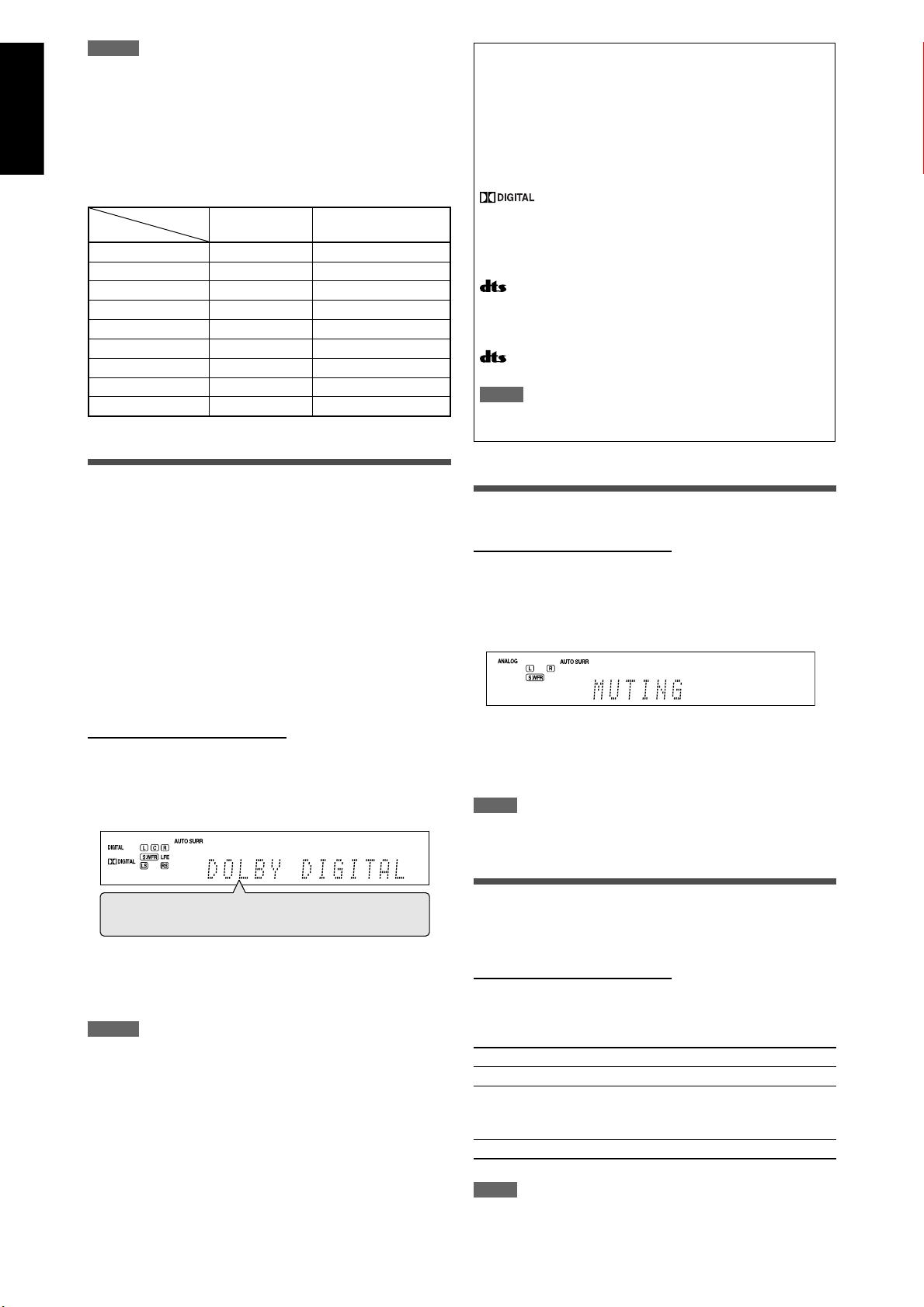
Selecting the digital decode mode
When “HDMI” or “DIGITAL” is selected for the audio input
setting (see page 21), this receiver automatically detects the
incoming digital signal format and sets the digital decode
mode to “DIGITAL AUTO.”
• The DIGITAL AUTO indicator lights up on the display.
If the following symptoms occur while playing Dolby Digital
or DTS software with “DIGITAL AUTO” selected, follow the
procedure below:
• Sound does not come out at the beginning of playback.
• Noise comes out while searching for or skipping chapters or
tracks.
The following digital signal format indicators on the display
indicate what type of signal comes into the receiver. See
pages 39 to 41 for the details of each digital signal format.
LINEAR PCM: • Lights up when Linear PCM signal comes
in.
• When the multi-channel PCM signal
comes in, “MULTI CH PCM” appears on
the display for a while.
Lights up when Dolby Digital signal comes
:
in.
• Flashes when “DOLBY DIGITAL” is
selected for any software other than
Dolby Digital.
:
96/24:
NOTE
When “DIGITAL AUTO” cannot recognize the incoming signal, no
digital signal format indicator lights up on the display.
Lights up when conventional DTS signal
comes in.
• Flashes when “DTS” is selected for any
software other than DTS.
Lights up when DTS 96/24 signal comes in.
Turning off the sounds temporarily
From the remote control ONLY:
Press MUTING to turn off the sound
through all connected speakers and
headphones.
“MUTING” appears on the display and the volume turns off.
From the remote control ONLY:
Press DECODE to select “DOLBY DIGITAL”
or “DTS.”
• Each time you press DECODE, the digital decode mode
changes as follows:
DIGITAL AUTO = DOLBY DIGITAL = DTS =
(Back to the beginning)
• To play back software encoded with Dolby Digital, select
“DOLBY DIGITAL.”
• To play back software encoded with DTS, select “DTS.”
NOTES
• The digital decode mode is fixed to “DIGITAL AUTO” when selecting
“USB” or “XM” as the source.
• “DOLBY DIGITAL” or “DTS” is automatically reset to “DIGITAL AUTO”
in the following cases:
– When you turn off the receiver.
– When you select another source.
– When you change the audio input setting (see page 21).
To restore the sound, press MUTING again.
• Pressing VOLUME +/– (or turning MASTER VOLUME control
on the front panel) also restores the sound.
NOTE
When performing Precise Surround Setup or turning the power off,
muting is automatically canceled.
Changing the display brightness
You can dim the display—Dimmer.
From the remote control ONLY:
Press DIMMER repeatedly.
• Each time you press the button, the display brightness
changes as follows:
DIMMER 1 Dims the display.
DIMMER 2 Dims the display more than DIMMER 1.
DIMMER 3 Turns off the display.
(Temporarily canceled when you operate the
receiver.)
DIMMER OFF Cancels the Dimmer (normal display).
NOTE
When performing Precise Surround Setup, Dimmer is automatically
canceled.
22
Page 25
English
Turning off the power with the Sleep
Timer
You can fall asleep while listening to music—Sleep Timer.
From the remote control ONLY:
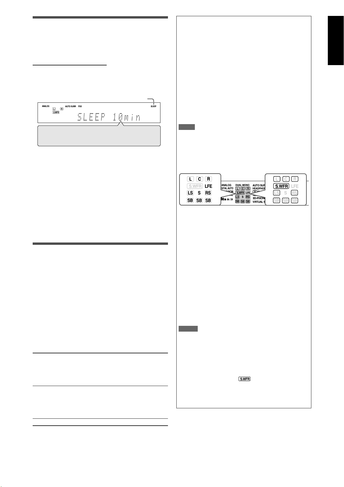
Press SLEEP repeatedly.
• Each time you press the button, the shut-off time changes
in 10-minute intervals. The SLEEP indicator lights up on the
display.
SLEEP indicator
Basic adjustment of auto memory
This receiver memorizes sound settings for each source:
• When you turn off the power
• When you change the source
When you change the source, the memorized settings for
the newly selected source are automatically recalled.
The following can be stored for each source:
• Video input setting (see page 21)
• Audio input setting (see page 21)
• CC Converter (see the left column)
• Midnight mode (see page 33)
• Digital equalization patterns (see page 36)
• Bass Boost (see page 37)
• Input attenuator mode (see page 37)
• Surround/DSP mode selection (see page 44)
10min = 20min = 30min = 40min =50min = 60min
= 70min = 80min =90min = OFF (Canceled) =
(Back to the beginning)
When the shut-off time comes:
The receiver turns off automatically.
To check the remaining time until the shut-off time:
Press SLEEP once.
The remaining time (in minutes) until the shut-off time
appears.
• To change the shut-off time, press SLEEP repeatedly.
To cancel the Sleep Timer:
Press SLEEP repeatedly so that “SLEEP OFF” appears on the
display. (The SLEEP indicator goes off.)
• The Sleep Timer is also canceled when you turn off the
receiver.
Making sounds natural
JVC’s CC (Compression Compensative) Converter eliminates
jitter and ripples, achieving a drastic reduction in digital
distortion by processing the digital music data in 24 bitquantization and by expanding the sampling frequency
to 176.4 kHz (for fs 44.1 kHz signals)/192 kHz (for fs 48 kHz
signals) on the front speakers.
By using the CC Converter, you can obtain a natural sound
field from both digital and analog sources.
• Once you have made an adjustment, it is memorized for
each source.
Press CC CONVERTER repeatedly.
• Each time you press the button, the mode changes as
follows:
CC CNVRTR 1 Select when playing back an analog source
or a digital source with non compressed
digital sound signal (Linear PCM).
The CC CONVERTER 1 indicator lights up on
the display.
CC CNVRTR 2 Select when playing back a source with
compressed digital sound signal (Dolby
Digital or DTS).
The CC CONVERTER 2 indicator lights up on
the display.
CC CNVRTR OFF Select when not using the CC Converter.
NOTE
If the source is “FM” or “AM,” you can assign a different setting for
each band.
Signal and speaker indicators on the display
Signal indicators Speaker indicators
The signal indicators light up as follows:
L: • When digital input is selected: Lights up when
the left channel signal comes in.
• When analog input is selected: Always lights up.
R: • When digital input is selected: Lights up when
the right channel signal comes in.
• When analog input is selected: Always lights up.
C: Lights up when the center channel signal comes in.
LS: Lights up when the left surround channel signal
comes in.
RS: Lights up when the right surround channel signal
comes in.
S: Lights up when monaural surround signal comes in.
SB: Lights up when the surround back channel signal
comes in.
LFE: Lights up when the LFE channel signal comes in.
NOTES
• When “A MULTI” is selected for the audio input setting (see page
21), all the signal indicators except “SB” and “S” light up.
• When playing back multi-channel digital sound recorded in DVD-
Audio with HDMI connection (see pages 9 and 21), the signal
indicators may not light up correctly.
The speaker indicators light up as follows:
• The subwoofer indicator (
“SUBWOOFER” is set to “YES.” For details, see page 30.
• The other speaker indicators light up only when the
corresponding speaker is set to “SML (small)” or “LRG
(large),” and also required for the current playback.
) lights up when
23
Page 26
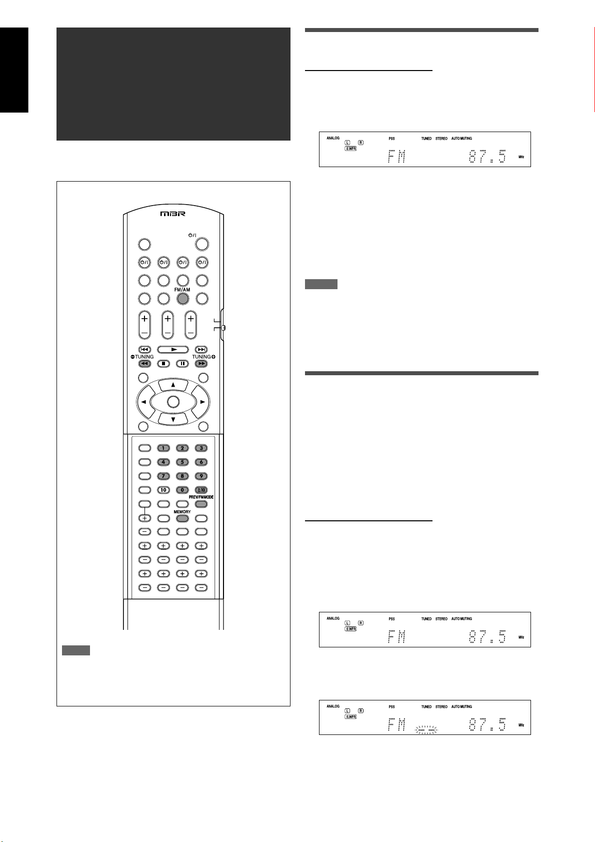
English
FM/AM tuner
operations
FM/AM tuner operations are mainly done from the remote
control.
Tuning in to stations manually
From the remote control ONLY:
1 Press FM/AM to select the band.
The last received station of the selected band is tuned in.
• Each time you press the button, the band alternates
between “FM” and “AM.”
2 Press repeatedly or hold TUNING 9 or
( TUNING until the station you want is
tuned in.
• Pressing (or holding) TUNING 9 increases the
frequency.
• Pressing (or holding) ( TUNING decreases the
frequency.
NOTES
• When you hold and release TUNING 9 or ( TUNING, the
frequency keeps changing until a station is tuned in.
• When a station of sufficient signal strength is tuned in, the TUNED
indicator lights up on the display.
• When an FM stereo program is received, the STEREO indicator also
lights up.
NOTE
When you have selected “FM” or “AM” by using SOURCE SELECTOR
on the front panel, the remote control may not work for tuner
operations. To use the remote control for tuner operations, select
“FM” or “AM” by using the FM/AM button on the remote control.
Using preset tuning
Once a channel number is assigned to a station, the station
can be quickly tuned in by selecting the number. You can
preset up to 30 FM and 15 AM stations.
7 To store the preset stations
Before you start, remember...
There is a time limit in doing the following steps. If the setting
is canceled before you finish, start from step
From the remote control ONLY:
1 Tune in to the station you want to preset
(see “Tuning in to stations manually”
above).
• If you want to store the FM reception mode for this
station, select the FM reception mode you want. See
“Selecting the FM reception mode” on page 25.
2 Press MEMORY.
The channel number position starts flashing on the display
for about 5 seconds.
2 again.
24
Page 27

English
3 Press the numeric buttons (0 – 9, h10)
to select a channel number while the
channel number position is flashing.
• For channel number 5, press 5.
• For channel number 10, press h10, 1, then 0.
• For channel number 25, press h10, 2, then 5.
On the front panel:
2 1, 3
Before you start, remember...
There is a time limit in doing the following steps. If the setting
is canceled before you finish, start from step
2 again.
4 Press MEMORY again while the selected
channel number is flashing on the
display.
The selected channel number stops flashing.
The channel number is assigned to the station.
5 Repeat steps 1 to 4 until you store all the
stations you want.
To erase a stored preset station:
Storing a new station on a used channel number erases the
previously stored one.
7 To tune in a preset station
From the remote control:
1 Press FM/AM to select the band.
The last received station of the selected band is tuned in
and the numeric buttons now work for selecting preset
channels.
• Each time you press FM/AM, the band alternate between
“FM” and “AM.”
2 Press the numeric buttons (0 – 9, h10) to
select a preset channel number.
• For channel number 5, press 5.
• For channel number 10, press h10, 1, then 0.
• For channel number 25, press h10, 2, then 5.
1 Turn SOURCE SELECTOR to select “FM” or
“AM.”
The last received station of the selected band is tuned in.
2 Press TUNER PRESET.
“P” appears on the display, and MULTI JOG now works for
selecting preset channels.
3 Turn MULTI JOG to select a preset
channel number.
• To increase the preset channel numbers, turn MULTI JOG
clockwise.
• To decrease the preset channel numbers, turn MULTI
JOG counterclockwise.
Selecting the FM reception mode
When an FM stereo broadcast is hard to receive or noisy, you
can change the FM reception mode.
• You can store the FM reception mode for each preset station
(see page 24).
From the remote control ONLY:
While listening to an FM station, press FM
MODE.
• Each time you press the button, the FM reception mode
alternates between “AUTO MUTING” and “MONO.”
AUTO MUTING Normally select this.
When a program is broadcast in stereo, you
will hear stereo sound; when in monaural,
you will hear monaural sound. This mode is
also useful to suppress static noise between
stations. The AUTO MUTING indicator lights
up on the display.
MONO Select this to improve the reception (but
stereo effect will be lost).
In this mode, you will hear noise while
tuning in to the stations. The AUTO MUTING
indicator goes off from the display. (The
STEREO indicator also goes off.)
Initial setting: AUTO MUTING
25
Page 28
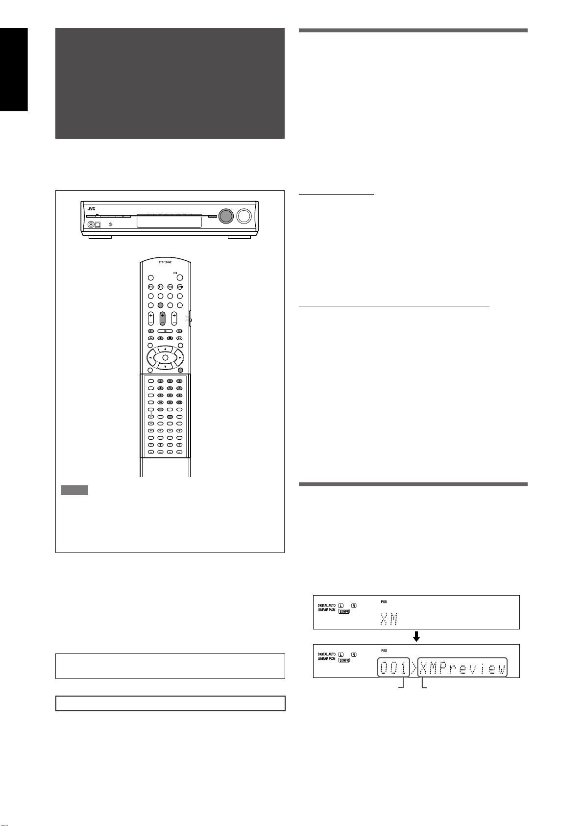
English
XM Satellite Radio
operations
This is an XM Ready® receiver.
• Before operating, refer also to the manual of your XM MiniTuner System (not supplied).
Preparation
To listening to XM Satellite Radio, you need the following:
– The XM Mini-Tuner System*
and XM Mini-Tuner Home Dock
– Subscription to XM Satellite Radio*
*1 To connect the XM Mini-Tuner System to this receiver, see
page 7.
2
*
The following channels are available without subscription:
– Channel 0: This channel is for checking the XM Satellite
Radio ID code.
– Channel 1: This is “XM Preview” channel.
How to subscribe
XM Satellite radio is a subscription service.
To subscribe to the XM Satellite Radio, visit the XM Satellite
Radio’s web site at <https://activate.xmradio.ca/onlineactivation/activation.jsp> for English, <https://activate.
xmradio.ca/online-activation/activation_fr.jsp> for French, or
you can call 1-877-GET-XMSR (1-877-438-9677).
For subscription, you need to have the XM Satellite radio ID
code. To check the ID code, follow the procedure below:
How to check the XM Satellite Radio ID code
After connection:
1
(not supplied)—XM Mini-Tuner
2
NOTE
When you have selected “XM” by using SOURCE SELECTOR on the
front panel, the remote control may not work for XM Satellite Radio
operations. To use the remote control for the XM Satellite Radio
operations, select “XM” by using the XM button on the remote
control.
7 About XM Satellite Radio
XM Satellite Radio is a satellite radio service with digitalquality sound and over 100 digital channels—100%
commercial-free music channels, over 20 channels of news,
sports, talk and entertainment. For the latest channel listings
and programming information, or to sign up, visit <http://
www.xmradio.ca>.
XM Ready® is a registered trademark of XM Satellite Radio
Inc. All rights reserved.
For SIRIUS Satellite Radio operations, see page 47.
1 Press XM on the remote control or turn
SOURCE SELECTOR on the front panel to
select “XM” as the source.
2 Tune in to “Channel 0” (see “To tune in to
channels” on page 27) to check your XM
Satellite Radio ID code.
The display alternately shows “RADIO ID” and the 8-digit
(alphanumeric) ID code.
To cancel the ID code display
Select any channel other than “Channel 0.”
Listening to the XM Satellite Radio
1 Press XM on the remote control or turn
SOURCE SELECTOR on the front panel to
select “XM” as the source.
The last received channel is tuned in.
“XM” appears and then the channel name appears on the
display.
Channel number Channel name
2 Tune in to the desired channel.
You can tune in to channels with one of the following
methods:
– Channel Search
– Category Search
– Direct Channel Access
For details, see “To tune in to channels” on page 27.
26
Page 29
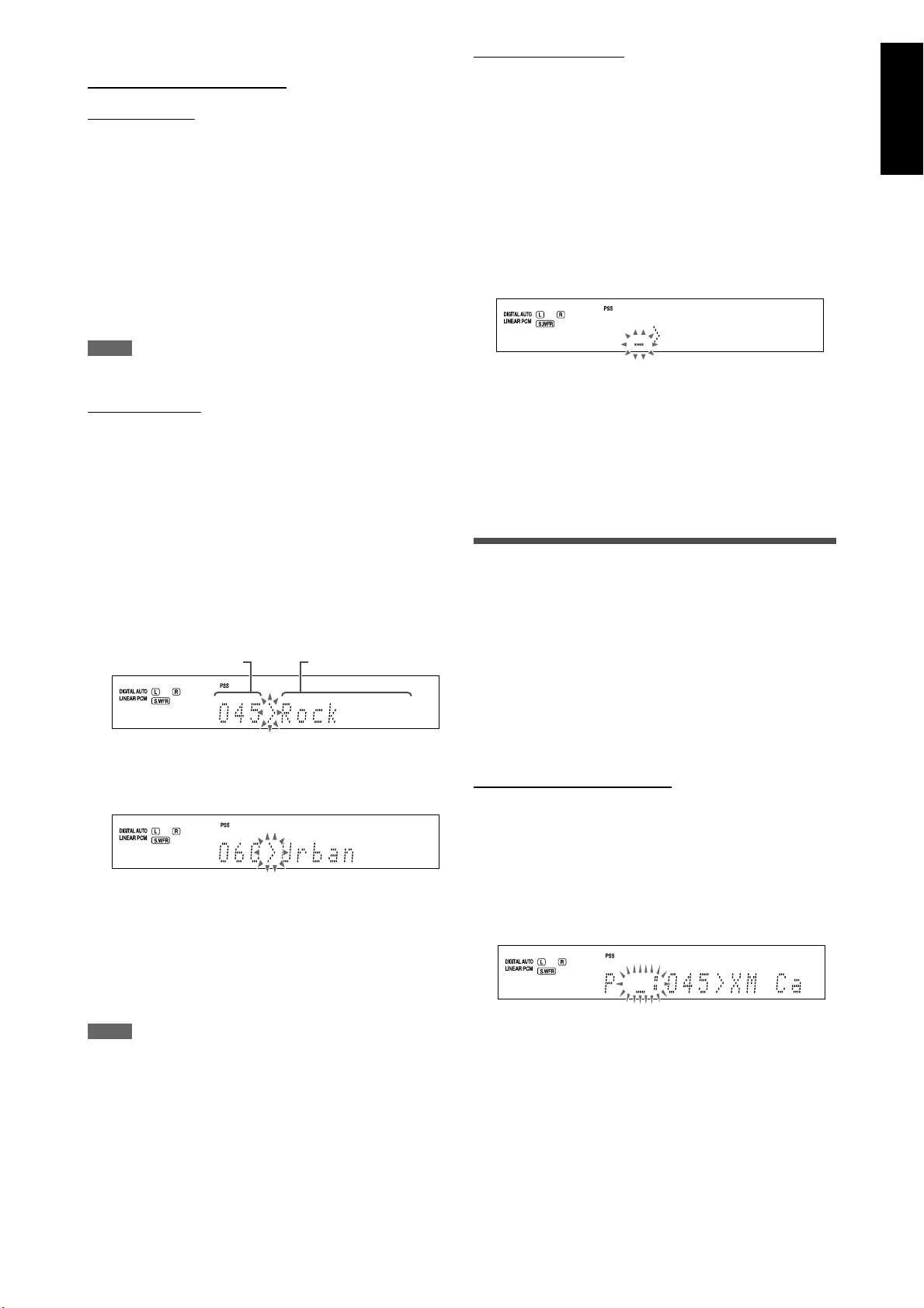
English
7 To tune in to channels
From the remote control ONLY:
Channel Search
You can search and tune in to all channels.
1 Press XM to select “XM” as the source.
2 Press repeatedly or hold CHANNEL
+/– until the desired channel number
appears on the display.
• Pressing (or holding) CHANNEL + increases the channel
number.
• Pressing (or holding) CHANNEL – decreases the channel
number.
NOTE
While searching, the invalid and unsubscribed channels are skipped.
Category Search
You can select the channel category and tune in to only the
channels included in the selected category.
Before you start, remember...
There is a time limit in doing the following steps. If the setting
is canceled before you finish, start from step
2 again.
Direct Channel Access
You can tune in to the desired channel directly by entering the
channel number.
Before you start, remember...
There is a time limit in doing the following steps. If the setting
is canceled before you finish, start from step
2 again.
1 Press XM to select “XM” as the source.
2 Press the DIRECT button.
The receiver enters the Direct Access mode and the
numeric buttons now work for entering channel numbers.
The channel number position starts flashing on the display
for about 5 seconds.
3 Press the numeric buttons (0 – 9, h10) to
enter the desired channel number while
the channel number position is flashing.
• For channel number 005, press 5.
• For channel number 010, press h10, 1, then 0.
• For channel number 025, press h10, 2, then 5.
• For channel number 115, press h10, h10, 1, 1, then 5.
1 Press XM to select “XM” as the source.
2 Press CAT 9 or ( CAT.
The receiver enters the Category Search mode.
The category name of the currently selected channel
appears and “>” starts flashing on the display for about 15
seconds.
Channel number Category name
3 Press CAT 9 or ( CAT repeatedly to
display the desired category name on
the display while “>” is flashing.
4 Press repeatedly or hold CHANNEL
+/– until the desired channel is tuned in.
• Pressing (or holding) CHANNEL + increases the channel
number included in the selected category.
• Pressing (or holding) CHANNEL – decreases the channel
number included in the selected category.
Using preset tuning
Once a preset number is assigned to a channel, the channel
can be quickly tuned in by selecting the number. You can
preset up to 30 channels.
7 To store the preset channels
Before you start, remember...
There is a time limit in doing the following steps. If the setting
is canceled before you finish, start from step
From the remote control ONLY:
1 Tune in to the channel you want to
preset (see “To tune in to channels” on
the left column).
2 Press MEMORY.
The preset number position starts flashing on the display
for about 5 seconds.
2 again.
NOTE
While searching, the invalid and unsubscribed channels are skipped.
3 Press the numeric buttons (0 – 9, h10) to
select a preset number while the preset
number position is flashing.
• For preset number 5, press 5.
• For preset number 10, press h10, 1, then 0.
• For preset number 25, press h10, 2, then 5.
Continued on the next page
27
Page 30
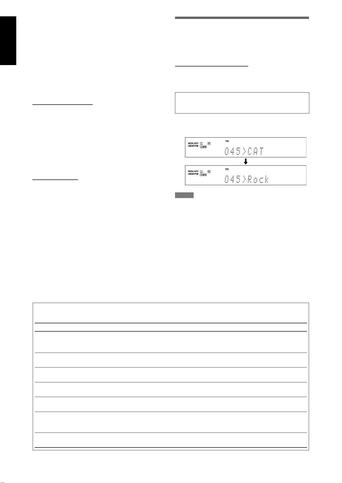
English
4 Press MEMORY again while the selected
preset number is flashing on the display.
5 Repeat steps 1 to 4 until you store all the
desired channels.
Changing the channel information
While listening to the XM Satellite Radio, the currently
selected channel information appears on the display.
You can change the type of channel information.
To erase a stored preset channel
Storing a new channel on a used preset number erases the
previously stored one.
7 To tune in a preset channel
From the remote control:
1 Press XM.
The last received channel is tuned in.
2 Press the numeric buttons (0 – 9, h10) to
select a preset channel number.
• For preset number 5, press 5.
• For preset number 10, press h10, 1, then 0.
• For preset number 25, press h10, 2, then 5.
On the front panel:
Before you start, remember...
There is a time limit in doing the following steps. If the setting
is canceled before you finish, start from step
2 again.
1 Turn SOURCE SELECTOR to select “XM.”
The last received channel is tuned in.
2 Press TUNER PRESET.
“P” flashes on the display, and MULTI JOG now works for
selecting preset channels.
From the remote control ONLY:
Press DISPLAY.
Each time you press the button, the channel information
changes as follows:
CHAN (channel name)* = NAME (artist name/feature) =
TITLE (song/program title) = CAT (category name) = (Back
to the beginning)
* CHAN (channel name) is the initial setting.
EX.: When the category name is selected:
After 1 second
NOTES
• If you turn off the power or select another source, the display is
changed back to the initial setting.
• When you tune in to another channel, the channel name appears
on the display and then the channel information you have selected
appears.
• When all the text information cannot be shown on the display at a
time, the text scrolls.
• Some characters cannot be displayed correctly.
3 Turn MULTI JOG to select a preset
number.
• To increase the preset numbers, turn MULTI JOG
clockwise.
• To decrease the preset numbers, turn MULTI JOG
counterclockwise.
7 Messages on the display
When problems occur, a message appears on the display. In this case, refer to the following solution.
Message Possible cause Solution
NO SIGNAL Signals are too weak. Move the XM Mini-Tuner Home Dock
antenna near a south-facing window or
where “Channel 1” can be heard clearly.
CHECK ANTENNA The XM Mini-Tuner Home Dock antenna
is not connected properly.
LOADING This receiver is loading the channel
information and audio data.
OFF AIR Selected channel is not currently
broadcasting any signal.
UPDATING The latest encryption code is being
updated.
• Channel number and “-----”
• Preset number, channel
number, and “-----”
• Channel number and “CH---”
• Preset number and “---<CH---”
No text information for the selected
channel is available. —
Selected channel does not exist or is not
subscribed yet.
Check the connection (see page 7).
It takes a few minutes to complete. Wait until
loading is finished.
Select another channel.
Wait until updating is finished.
—
28
Page 31

English
Basic settings
To obtain the best possible sound effect from the Surround/
DSP modes (see pages 39 to 44), you need to set up the
speaker and subwoofer information after all the connections
are completed. From pages 29 to 34, how to set speakers and
other basic items of the receiver are explained.
Basic setting items
You can adjust the following items. See pages in parentheses
for details.
• You cannot select the items which is not available with the
current setting. For example, when “S BACK SPK” is set to
“NO,” you cannot select the following items:
S BACK OUT, S BACK DIST, S BACK L DIST, S BACK R DIST
Items To do
SUBWOOFER* Register your subwoofer. (30)
FRONT SPK* Register your front speaker size. (30)
CENTER SPK* Register your center speaker size. (30)
SURROUND SPK* Register your surround speaker size. (30)
S BACK SPK* Register your surround back speaker
size. (30)
S BACK OUT* Register the number of your surround
back speaker(s). (31)
DIST UNIT Select the measuring unit for the
speaker distance. (31)
FRONT L DIST* Register the distance from the left front
speaker to your listening point. (31)
FRONT R DIST* Register the distance from the right
front speaker to your listening point.
(31)
CENTER DIST* Register the distance from the center
speaker to your listening point. (31)
SURR L DIST* Register the distance from the left
surround speaker to your listening
point. (31)
SURR R DIST* Register the distance from the right
surround speaker to your listening
point. (31)
S BACK DIST* Register the distance from the surround
back speaker to your listening point
when using a single speaker for the
surround back speaker. (31)
S BACK L DIST* Register the distance from the left
surround back speaker to your listening
point. (31)
S BACK R DIST* Register the distance from the right
surround back speaker to your listening
point. (31)
Items To do
EX/ES/PLIIx Select the EX/ES/PLIIx reproduction
mode. (32)
DUAL MONO Select the Dual Mono sound channel.
(32)
SUBWOOFER OUT Select sounds emitted from the
subwoofer. (33)
CROSSOVER* Select the cutoff frequency to the
subwoofer. (33)
LFE ATT Attenuate the bass (LFE) sounds. (33)
MIDNIGHT MODE Reproduce a powerful sound at night.
(33)
DIGITAL IN 1 Select the component connected to the
digital coaxial terminal—1(DVR/DVD).
(34)
DIGITAL IN 2 Select the component connected to the
digital optical terminal—2(DBS). (34)
DIGITAL IN 3 Select the component connected to the
digital optical terminal—3(VCR). (34)
AUDIO DELAY Set the audio delay time to correct
synchronization between video and
audio signals. (34)
HDMI SELECT Select the source for HDMI VCR (DBS) IN
terminal. (34)
CMPNT SELECT Select the source for COMPONENT VCR
(DBS) IN jacks. (34)
VIDEO OUTPUT Select the output video signal. (34)
* If you have performed Precise Surround Setup on pages 16
to 18, these settings are not required.
NOTE
Some items above are not available in the following cases below:
– When selecting “A MULTI” for the audio input setting (see page 11)
– When multi-channel PCM signals (see page 41) are coming in with
selecting “HDMI” for the audio input setting (see page 11)
29
Page 32

English
Operating procedure
1, 7 3, 5 2, 4
Setting the speakers
To obtain the best possible surround effect from the Surround
and DSP modes, register the setting about the speaker after all
connections are completed.
• If you have performed Precise Surround Setup on pages 16
to 18, the following settings are not required.
On the front panel ONLY:
Before you start, remember...
There is a time limit in doing the following steps. If the setting
is canceled before you finish, start from step
Ex.: When setting the DIGITAL IN 1 terminal
1 again.
1 Press SETTING.
MULTI JOG now works for the setting operation.
2 Turn MULTI JOG until the item you want
to set appears on the display.
• As you turn MULTI JOG, the setting items change as
follows:
SUBWOOFER Ô FRONT SPK Ô CENTER SPK Ô
SURROUND SPK Ô S BACK SPK Ô S BACK OUT Ô
DIST UNIT Ô FRONT L DIST Ô FRONT R DIST Ô
CENTER DIST Ô SURR L DIST Ô SURR R DIST Ô
S BACK DIST Ô S BACK L DIST Ô S BACK R DIST Ô
EX/ES/PLIIx Ô DUAL MONO Ô SUBWOOFER OUT
Ô CROSSOVER Ô LFE ATT Ô MIDNIGHT MODE Ô
DIGITAL IN 1 Ô DIGITAL IN 2 Ô DIGITAL IN 3 Ô
AUDIO DELAY Ô HDMI SELECT Ô CMPNT SELECT
Ô VIDEO OUTPUT Ô (Back to the beginning)
3 Press SET.
The current setting of the selected item appears.
7 Setting subwoofer information—
SUBWOOFER
Select if you have connected a subwoofer or not.
SUBWFR YES Select when you have connected a
subwoofer.
The subwoofer indicator (
the display. You can adjust the subwoofer
output level (see page 36).
SUBWFR NO Select when you have not connected a
subwoofer. Selecting this changes the front
speaker size to “LRG” (see below).
Initial setting: NO
) lights up on
7 Setting the speaker size—FRONT SPK (front
speakers), CENTER SPK (center speaker),
SURROUND SPK (surround speakers), S BACK
SPK (surround back speakers)
Register the sizes of all the connected speakers.
LRG (large) Select when the cone speaker size is larger
than 12 cm.
SML (small) Select when the cone speaker size is smaller
than 12 cm.
NO Select when you have not connected
the speaker. (Not selectable for the front
speakers.)
Initial setting: LRG (for the front speakers)
SML (for the other speakers)
4 Turn MULTI JOG to select the appropriate
setting.
DVR/DVD Ô DBS Ô VCR Ô TV
5 Press SET.
Your setting is stored.
6 Repeat steps 2 to 5 to set other items if
necessary.
7 Press SETTING.
The source indication resumes on the display.
NOTES
• If you have selected “SML (small)” for the front speaker size, you
cannot select “LRG (large)” for other speakers.
• When “SUBWOOFER” is set to “NO,” the front speaker size is fixed to
“LRG (large)” (and you cannot select “SML (small)”).
• When “SURROUND SPK” is set to “SML (small),” you cannot select
“LRG (large)” for the surround back speaker.
• When “SURROUND SPK” is set to “NO,” the surround back speaker is
fixed to “NO.”
30
Page 33

English
7 Setting the surround back speaker(s)—
S BACK OUT
Register the number of the surround back speaker(s).
SB OUT 1SPK Select when you use a single surround back
speaker.
SB OUT 2SPK Select when you use 2 surround back
speakers.
Initial setting: 2SPK
NOTES
• When “S BACK SPK” is set to “NO,” you cannot select “S BACK OUT.”
• When “S BACK OUT” is set to “1SPK,” connect the surround back
speaker to the left surround back speaker terminal (see page 8). No
sound comes from the surround back speaker if you connect it to
the right surround back speaker terminal.
7 Setting the speaker distance
The distance from your listening position to the speakers is
one of the important elements to obtain the best possible
sound effect from the Surround/DSP modes.
By referring to the speaker distance, the receiver automatically
sets the delay time of the sound through each speaker so that
sounds through all the speakers can reach you at the same
time.
C
FL FR
2.7 m
(9 ft)
2.1 m
2.4 m
(7 ft)
(8 ft)
SBL SBR
In this case, set the distance as follows:
Left front speaker (FL): 3.0 m (10 ft)
Right front speaker (FR): 3.0 m (10 ft)
Center speaker (C): 3.0 m (10 ft)
Left surround speaker (SL): 2.7 m (9 ft)
Right surround speaker (SR): 2.7 m (9 ft)
Left surround back speaker (SBL): 2.4 m (8 ft)
Right surround back speaker (SBR): 2.4 m (8 ft)
3.3 m
(11 ft)
3.0 m
(10 ft)
SRSL
• Measuring unit—DIST UNIT
Select which measuring unit you use.
D UNIT meter Select to set the distance in meters.
D UNIT feet Select to set the distance in feet.
Initial setting: meter
• Speaker distance—
FRONT L DIST (for the left front speaker), FRONT R DIST
(for the right front speaker), CENTER DIST (for the
center speaker), SURR L DIST (for the left surround
speaker), SURR R DIST (for the right surround speaker),
S BACK L DIST (for the left surround back speaker),
S BACK R DIST (for the right surround back speaker)
Adjustable range: 0.3 m to 9.0 m in 0.15 m intervals
(1 ft to 30 ft in 0.5 ft intervals)
Initial setting: 3.0 m (10 ft) for all speakers
NOTES
• You cannot set the speaker distance for the speakers you have set
to “NO.”
• If you have selected “1SPK” for “S BACK OUT” (see the left column),
“S BACK DIST” appears instead of “S BACK L DIST” and “S BACK R
DIST.”
31
Page 34

English
Activating the EX/ES/PLIIx setting—
Selecting the main or sub channel—
EX/ES/PLIIx
Depending on this setting, available Surround modes for
digital multi-channel software vary—EX/ES/PLIIx (7.1channel) reproduction or 5.1-channel reproduction. Select an
appropriate setting for your enjoyment.
• For details about relation between EX/ES/PLIIx setting and
available Surround mode, see page 42.
• To activate the Surround mode, see page 43.
AUTO According to the incoming signal, an
appropriate Surround mode is applied.
• For Dolby Digital Surround EX and DTS-ES
software, 7.1-channel reproduction is
applied*.
• For other multi-channel (4 channels or
more) encoded software, 5.1-channel
reproduction is applied.
ON Select to apply 7.1-channel reproduction to
both 5.1-channel and 6.1-channel encoded
software.
PLIIx MOVIE Select to apply PLIIx MOVIE (7.1-channel)
reproduction to both 5.1-channel and 6.1channel encoded software.
PLIIx MUSIC Select to apply PLIIx MUSIC (7.1-channel)
reproduction to both 5.1-channel and 6.1channel encoded software.
OFF Select to cancel the EX/ES/PLIIx (7.1-
channel) reproduction.
Initial setting: AUTO
* For some Dolby Digital Surround EX software, Dolby Digital
5.1-channel reproduction (“DOLBY DIGITAL”) may be
applied even though you have selected “AUTO.” In this case,
select “ON” to apply “DOLBY D EX.” (See page 42.)
DUAL MONO
You can select the playback sound (channel) you want while
playing digital software recorded (or broadcasted) in Dual
Mono mode (see page 41), which includes two monaural
channels separately. When the receiver detects Dual Mono
signals, the DUAL MONO indicator lights up on the display.
D MONO MAIN Select to play back the main channel (Ch
1).*
Signal indicator “L” lights up while playing
back this channel.
D MONO SUB Select to play back the sub-channel (Ch
2).*
Signal indicator “R” lights up while playing
back this channel.
D MONO ALL Select to play back both the main and sub-
channels (Ch 1/Ch 2).*
Signal indicators “L” and “R” light up while
playing back these channels.
Initial setting: MAIN
* Dual Mono signals can be heard from the following
speakers—L (left front speaker), R (right front speaker), and
C (center speaker), with respect to the current Surround
setting:
Dual
Mono
setting
MAIN Ch 1 Ch 1 — Ch 1 — Ch 1 Ch 1
SUB Ch 2 Ch 2 — Ch 2 — Ch 2 Ch 2
ALL Ch 1 Ch 2 — Ch 1+Ch 2 — Ch 1+Ch 2 Ch 1+Ch 2
Without
Surround
LRL C R L R
With Surround Activated
Center speaker setting
SML/LRG NO
NOTES
• This function is not available when “SURROUND SPK” is set to “NO”
(see page 30).
• When “S BACK SPK” is set to “NO” (see page 30), the Virtual
Surround Back (see page 43) is applied for EX/ES/PLIIx (7.1-channel)
reproduction.
NOTE
The Dual Mono format is not identical with bilingual broadcasting for
TV programs. So this setting does not take effect while watching such
bilingual programs.
32
Page 35

English
Setting bass sound
7 Setting subwoofer output—SUBWOOFER OUT
The subwoofer emits the LFE signals* and the bass elements
of each speaker set “SML (small).”
You can also make the bass elements of the front speakers
(MAIN) emitted through the subwoofer.
SW LFE The subwoofer emits the LFE signals and
the bass elements of the speakers set to
“SML (small).”
SW LFE+MAIN The subwoofer emits the LFE signals and
the bass elements of the speakers set to
“SML (small).” The subwoofer also emits
the bass elements of front speakers (MAIN)
when no LFE signal nor the bass elements
of “SML (small)” speakers exist.
Initial setting: LFE
* The LFE signals are emitted only when playing the following
software with the LFE signals:
– Dolby Digital multi-channel software
– DTS multi-channel software
When playing analog source or linear PCM software, no LFE
signal is emitted.
NOTE
When “SUBWOOFER” is set to “NO” (see page 30), you cannot select
“SUBWOOFER OUT.”
7 Setting the low frequency effect attenuator
—LFE ATT
If the bass sound is distorted while playing back software
encoded with Dolby Digital or DTS, set the LFE level to
eliminate distortion.
• This function takes effect only when the LFE signals come in.
LFE 0dB Normally select this.
LFE –10dB Select when the bass sound is distorted.
Initial setting: 0 dB
Using the Midnight mode—
MIDNIGHT MODE
You can enjoy a powerful sound at night using the Midnight
mode.
When the Midnight mode is activated, the MIDNIGHT
indicator lights up on the display.
MIDNIGHT OFF Select when you want to enjoy surround
with its full dynamic range. (No effect
applied.)
MIDNIGHT 1 Select when you want to reduce the
dynamic range a little.
MIDNIGHT 2 Select when you want to apply the
compression effect fully (useful at night).
Initial setting: OFF
7 Setting the crossover frequency—CROSSOVER
Small speakers cannot reproduce the bass sounds efficiently.
If you use a small speaker in any position, this receiver
automatically reallocates the bass sound elements assigned to
the small speaker to the large speakers.
To use this function properly, set this crossover frequency
level according to the size of the small speaker connected.
• If you have selected “LRG (large)” for all speakers (see page
30), this function will not take effect (“CROSS OFF” appears).
• If you have performed Precise Surround Setup on pages 16
to 18, this setting is not required.
Adjustable range: 80 Hz to 200 Hz (in 10 Hz intervals)
Initial setting: 100 Hz
The following are examples of the setting:
CROSS 80Hz Select when the cone speaker unit built in
the speaker is about 12 cm.
CROSS 100Hz Select when the cone speaker unit built in
the speaker is about 10 cm.
CROSS 120Hz Select when the cone speaker unit built in
the speaker is about 8 cm.
CROSS 150Hz Select when the cone speaker unit built in
the speaker is about 6 cm.
CROSS 200Hz Select when the cone speaker unit built in
the speaker is less than 5 cm.
NOTE
Crossover frequency is not valid for the HEADPHONE and 3D
HEADPHONE modes.
33
Page 36

English
Setting the digital input (DIGITAL IN)
Selecting the source for HDMI
terminals—DIGITAL IN 1/2/3
When you use the digital input terminals, register what
components are connected to which terminals—DIGITAL
IN 1/2/3 (see page 14) so that the correct source name will
appear when you select the digital source.
Select one of the following components for each terminal:
DVR/DVD For the DVD player (or DVD recorder)
DBS For the DBS tuner
VCR For the VCR
TV For the TV
Initial setting: DVR/DVD (for “DIGITAL IN 1”)
DBS (for “DIGITAL IN 2”)
VCR (for “DIGITAL IN 3”)
NOTES
• You cannot assign the same component for different terminals.
The priority order for assignment is as follows:
“DIGITAL IN 1” > “DIGITAL IN 2” > “DIGITAL IN 3”
Ex.: When “DIGITAL IN 1” is set to “DVR/DVD.”
DIGITAL IN 1 DVR/DVD DBS VCR TV
‘
For “DIGITAL IN 2,” “DBS,” “VCR,” and “TV” are selectable.
• In this case, “VCR” is selected.
DIGITAL IN 2 DVR/DVD DBS VCR TV
‘
For “DIGITAL IN 3,” “DBS” and “TV” are selectable.
DIGITAL IN 3 DVR/DVD DBS VCR TV
: Selectable : Not selectable
• Setting “DIGITAL IN 1” affects “DIGITAL IN 2” and “DIGITAL IN 3”
settings. When you have changed “DIGITAL IN 1,” confirm the
components assigned to “DIGITAL IN 2” and “DIGITAL IN 3.”
Setting the Audio delay level—
AUDIO DELAY
Synchronization between audio and video reproduction can
be possibly disturbed because video signal decoding is timeconsuming compared to the audio signal decoding.
On this setting, you can correct synchronization between
video and audio signals by delaying the audio signal timing.
terminal and COMPONENT VIDEO
jacks—HDMI SELECT/CMPNT SELECT
When you connect a VCR or DBS to the HDMI VCR(DBS) IN
terminal or COMPONENT VIDEO jacks on the rear of the
receiver, you need to select either “VCR” or “DBS” for each
terminal according to the component you connect.
If you have not selected an appropriate source, you cannot
view the playback picture on the TV.
For the HDMI terminal:
HDMI VCR Select this when connecting a VCR to the
HDMI terminal.
HDMI DBS Select this when connecting a DBS tuner to
the HDMI terminal.
Initial setting: VCR
For the COMPONENT VIDEO jacks:
CMPNT VCR Select this when connecting a VCR to the
COMPONENT VIDEO jacks.
CMPNT DBS Select this when connecting a DBS tuner to
the COMPONENT VIDEO jacks.
Initial setting: VCR
Selecting the output video signals—
VIDEO OUTPUT
When you connect your TV and this receiver with the HDMI
cable, set this setting to “HDMI.”
With this setting, this receiver converts incoming composite
video, S-video, and component video signals from video
components and transmits the converted signals through the
HDMI cable.
VIDEO HDMI Select this when connecting a TV to the
HDMI terminal.
VIDEO OTHER Select this when connecting a TV to any
video jack other than the HDMI terminal.
Initial setting: HDMI
NOTE
When selecting “HDMI,” the AV COMPU LINK remote control system is
restricted (see page 45).
Adjustable range: OFF and 10 ms to 150 ms (in 10 ms
intervals)
Initial setting: OFF
NOTE
The audio delay level setting does not take effect when selecting “A
MULTI” for the audio input setting (see page 11).
34
Page 37

English
Sound adjustments
You can make sound adjustment to your preference after
completing basic setting.
Basic adjustment items
You can adjust the following items. See pages in parentheses
for details.
• You cannot select the items which is not available with the
current setting.
Items To do
SUBWFR LVL*
FRONT L LVL*
FRONT R LVL*
CENTER LVL*
SURR L LVL*
SURR R LVL*
S BACK LVL*
S BACK L LVL*
S BACK R LVL*
D EQ 63Hz*
D EQ 250Hz*
D EQ 1kHz*
D EQ 4kHz*
D EQ 16kHz*
BASS BOOST Boost the bass level. (37)
INPUT ATT Attenuate the input level of analog source.
EFFECT Adjust the effect level. (37)
ROOM SIZE Select the room size for your virtual
LIVENESS Select the liveness level for your virtual
PANORAMA Add “wraparound” sound effect with
CENTER WIDTH Adjust the center channel localization
DIMENSION Adjust sound localization pattern. (38)
CENTER GAIN Adjust the sound localization of the center
CENTER TONE Make the center tone soft or sharp. (38)
CENTER ALIGN Align the vertical localization of the center
1
*
You can adjust these items directly from the remote control.
2
*
If you have performed Precise Surround Setup on pages 16
to 18, these settings are not required.
1, 2
Adjust the subwoofer output level. (36)
1, 2
Adjust the left front speaker output level.
(36)
1, 2
Adjust the right front speaker output level.
(36)
1, 2
Adjust the center speaker output level. (36)
1, 2
Adjust the left surround speaker output
level. (36)
1, 2
Adjust the right surround speaker output
level. (36)
1, 2
Adjust the surround back speaker output
level when using a single speaker for the
surround back speaker. (36)
1, 2
Adjust the left surround back speaker
output level. (36)
1, 2
Adjust the right surround back speaker
output level. (36)
1
Adjust the equalization pattern of each
1
band. (36)
1
1
1
(37)
listening room. (37)
listening room. (37)
sidewall image. (37)
between the center speaker and the left/
right speakers. (38)
channel. (38)
channel signals. (38)
NOTE
Some items are not available in the following cases below:
– When selecting “A MULTI” for the audio input setting (see page 11)
– When multi-channel PCM signals (see page 41) are coming in with
selecting “HDMI” for the audio input setting (see page 11)
Operating procedure
On the front panel:
1, 7 3, 5 2, 4
Before you start, remember...
There is a time limit in doing the following steps. If the setting
is canceled before you finish, start from step
Ex.: When adjusting subwoofer output level.
1 Press ADJUST.
MULTI JOG now works for the sound adjustment.
2 Turn MULTI JOG until the item you want
to adjust appears on the display.
• As you turn MULTI JOG, the adjustment items change as
follows:
SUBWFR LVL Ô FRONT L LVL Ô FRONT R LVL Ô
CENTER LVL Ô SURR L LVL Ô SURR R LVL Ô
S BACK LVL Ô S BACK L LVL Ô S BACK R LVL Ô
D EQ 63Hz Ô D EQ 250Hz Ô D EQ 1kHz Ô
D EQ 4kHz Ô D EQ 16kHz Ô BASS BOOST Ô
INPUT ATT Ô EFFECT Ô ROOM SIZE Ô
LIVENESS Ô PANORAMA Ô CENTER WIDTH Ô
DIMENSION Ô CENTER GAIN Ô CENTER TONE Ô
CENTER ALIGN Ô (Back to the beginning)
3 Press SET.
The current setting for the selected item appears.
4 Turn MULTI JOG to adjust the selected
item.
–10 0 +10
5 Press SET.
Your adjustment is stored.
6 Repeat steps 2 to 5 to adjust other items
if necessary.
7 Press ADJUST.
The source indication resumes on the display.
1 again.
35
Page 38

English
Adjusting the speaker output levels
• SUBWFR LVL (subwoofer output level)
• FRONT L LVL (left front speaker output level)
• FRONT R LVL (right front speaker output level)
• CENTER LVL (center speaker output level)
• SURR L LVL (left surround speaker output level)
• SURR R LVL (right surround speaker output level)
• S BACK LVL (surround back speaker output level)
• S BACK L LVL (left surround back speaker output level)
• S BACK R LVL (right surround back speaker output level)
Adjusting the equalization
patterns—D EQ 63Hz/250Hz/1kHz/
4kHz/16kHz
You can adjust equalization patterns in five frequency bands
(center frequency: 63 Hz, 250 Hz, 1 kHz, 4 kHz, 16 kHz) for the
front speakers.
• Once you have made an adjustment, it is memorized for
each source.
You can adjust the speaker output levels.
By using Precise Surround Setup (see pages 16 to 18), you can
set the output levels of all the speakers to the same levels.
Adjustable range: –10 (dB) to +10 (dB) (in 1 dB intervals)
Initial setting: 0 (dB) for all speakers
NOTES
• If you have selected “NO” for a speaker (see page 30), the output
level for the corresponding speaker is not adjustable.
• If you have selected “1SPK” for “S BACK OUT” (see page 31), “S BACK
LVL” appears instead of “S BACK L LVL” and “S BACK R LVL.”
• While using the headphones, you cannot adjust the speaker output
levels.
From the remote control:
1 Press TEST to check the speaker output
balance.
“TEST FL” starts flashing on the display, and test tones
come out of the speakers clockwise.
FL = C = FR = SR = SBR*
= SBL* = SL = SW =
(Back to the beginning)
1, 3
2
Adjustable range: –8 (dB) to +8 (dB) (in 2 dB intervals)
Initial setting: 0 (dB) for all bands
• When making an adjustment, the DIGITAL EQ indicator
lights up on the display.
If no adjustment is required, set all the frequency bands to
“0 (dB).”
• The DIGITAL EQ indicator goes off from the display.
From the remote control:
Before you start, remember...
There is a time limit in doing the following steps. If the
setting is canceled before you finish, start from step
1 again.
1 Press D. EQ FREQ repeatedly to
select the band you want
to adjust.
2 Press D. EQ LEVEL + or – to
adjust the equalization
pattern of the selected
band.
3 Repeat steps 1 and 2 to
adjust other bands.
1
2
• You can adjust the speaker output levels without the
test tone.
2 Adjust the speaker output levels.
Press the + or – button corresponding to the speaker
you want to adjust.
3 Press TEST again to stop the test tone.
* When using a single speaker for the surround back
speaker, the test tone comes out of “SB” instead of “SBR”
and “SBL.”
NOTES
• No test tone comes out of the speakers for which the speaker
setting is set to “NO” (see page 30).
• No test tone is available when the headphones are in use.
• If you have selected “1SPK” for “S BACK OUT” (see page 31), press
S. BACK L +/– to adjust the output level.
• When the PSS indicator is lit, the frequency response of each
channel appears on the display with the test tone. (See page 18.)
36
Page 39

English
Reinforcing the bass—BASS BOOST
You can boost the bass level—Bass Boost.
• Once you have made an adjustment, it is memorized for
each source.
• You cannot adjust directly from the remote control.
B BOOST ON Select to boost the bass level.
The B.BOOST indicator lights up on the
display.
B BOOST OFF Select to deactivate the Bass Boost.
Initial setting: OFF
7 Adjusting the virtual room size for DSP
modes—ROOM SIZE
This setting is available only when one of the DSP modes
(except All Channel Stereo) is in use. To activate DSP mode,
see pages 43 and 44.
• If “SURROUND SPK” is set to “NO” (see page 30), this item is
not adjustable.
• Once you have made an adjustment, it is memorized for
each DSP mode.
Adjustable range: 1 to 5 (in 1 step intervals)
Initial setting: 3
NOTE
This function affects only the sound coming out through the front
speakers.
Attenuating the input signal—
INPUT ATT
When the input level of analog source is too high, the sound
will be distorted. If this happens, you need to attenuate the
input signal level to prevent the sound distortion.
• Once you have made an adjustment, it is memorized for
each source.
• You cannot adjust directly from the remote control.
ATT ON Select to attenuate the input signal level.
The INPUT ATT indicator lights up on the
display.
ATT NORMAL Select to deactivate attenuation.
Initial setting: NORMAL
Adjusting the sound parameters for
the Surround/DSP modes
You can adjust the Surround/DSP sound parameters to your
preference.
• For details about the Surround/DSP modes, see pages 39 to
44.
• You cannot adjust these items directly from the remote
control.
7 Adjusting the effect level for DSP modes—
EFFECT
This setting is available only when one of the DSP modes
(except All Channel Stereo) is in use. To activate DSP mode,
see pages 43 and 44.
• Once you have made an adjustment, it is memorized for
each DSP mode.
As the number increases, the interval between reflections
increases so that you will feel as if you were in a larger room.
Normally, select “3.”
7 Adjusting the liveness effect for DSP
modes—LIVENESS
This setting is available only when one of the DSP modes
(except All Channel Stereo) is in use. To activate DSP mode,
see pages 43 and 44.
• If “SURROUND SPK” is set to “NO” (see page 30), this item is
not adjustable.
• Once you have made an adjustment, it is memorized for
each DSP mode.
Adjustable range: 1 to 5 (in 1 step intervals)
Initial setting: 3
As the number increases, the attenuation level of reflections
over time decreases so that acoustics change from “Dead” to
“Live.”
Normally, select “3.”
7 Adjusting the panorama control for Pro Logic
IIx Music and Pro Logic II Music—PANORAMA
This setting is available when Pro Logic IIx Music or Pro Logic
II Music is activated for the analog or digital 2-channel sound
signal.
To activate Pro Logic IIx Music or Pro Logic II Music, see pages
43 and 44.
• Once you have made an adjustment, it is memorized until
you change the setting.
PANORAMA ON Select to add “wraparound” sound effect
with side-wall image.
PANORAMA OFF Select to listen to originally recorded
sound.
Initial setting: OFF
Adjustable range: 1 to 5 (in 1 step intervals)
Initial setting: 3
As the number increases, the effect becomes stronger.
Normally, select “3.”
37
Page 40

English
7 Adjusting the center channel localization for
Pro Logic IIx Music and Pro Logic II Music—
CENTER WIDTH
This setting is available when Pro Logic IIx Music or Pro Logic
II Music is activated for the analog or digital 2-channel sound
signal.
To activate Pro Logic IIx Music or Pro Logic II Music, see pages
43 and 44.
• If “CENTER SPK” is set to “NO” (see page 30), this item is not
adjustable.
• Once you have made an adjustment, it is memorized until
you change the setting.
Adjustable range: OFF and 1 to 7 (in 1 step intervals)
Initial setting: 3
As the number increases, the center channel sound moves
toward the left and right speakers.
Normally, select “3.”
7 Adjusting the sound localization position
for Pro Logic IIx Music and Pro Logic II Music
—DIMENSION
This setting is available when Pro Logic IIx Music or Pro Logic
II Music is activated for the analog or digital 2-channel sound
signal.
To activate Pro Logic IIx Music or Pro Logic II Music, see pages
43 and 44.
• Once you have made an adjustment, it is memorized until
you change the setting.
Adjustable range: 1 to 7 (in 1 step intervals)
Initial setting: 4
7 Adjusting the center tone—CENTER TONE
This setting is available when one of the Surround/DSP modes
is in use. To activate Surround/DSP mode, see pages 43 and
44.
• If “CENTER SPK” is set to “NO” (see page 30), this item is not
adjustable.
• This setting is common to all Surround modes, and is
memorized separately for DSP modes.
Adjustable range: 1 to 5 (in 1 step intervals)
Initial setting: 3
As the number increases, the dialogue becomes stronger.
Normally, select “3.”
• When the center tone is set to other than “3,” the C.TONE
indicator lights up on the display.
7 Aligning the vertical localization of the
center channel for Surround/DSP modes—
CENTER ALIGN
This setting is available when one of the Surround/DSP modes
(except Pro Logic IIx Music, Pro Logic II Music, Neo:6 Music,
and All Channel Stereo) is in use. To activate Surround/DSP
mode, see pages 43 and 44.
• If “CENTER SPK” is set to “NO” (see page 30), this item is not
adjustable.
• Once you have made an adjustment, it is memorized for
each Surround/DSP mode.
C ALIGN ON Select this when you cannot feel as if the
actors or singers are speaking or singing on
the screen.
C ALIGN OFF Center alignment is turned off.
Initial setting: OFF
As the number increases, the sound localization moves
towards forward from backward.
Normally, select “4.”
7 Adjusting the sound localization of the center
channel—CENTER GAIN
This setting is available only when Neo:6 Music is in use.
• If “CENTER SPK” is set to “NO” (see page 30), this item is not
adjustable.
• Once you have made an adjustment, it is memorized until
you change the setting.
Adjustable range: 0 to 1.0 (in 0.1 step intervals)
Initial setting: 0.3
As the number increases, the center channel will be localized
clearly.
Normally, select “0.3.”
38
Page 41

English
Creating realistic
Introducing the Surround modes
sound fields
Reproducing theater ambience
In a movie theater, many speakers are located on the walls to
reproduce impressive multi-channel sound, reaching you from
all directions.
With these many speakers, sound localization and sound
movement can be expressed.
Surround/DSP modes built in this receiver can create almost
the same Surround sound as you can feel in a real movie
theater.
7 Dolby Digital*
Dolby Digital is a digital signal compression method,
developed by Dolby Laboratories, and enables multi-channel
encoding and decoding.
• When Dolby Digital signal is detected through the digital
input, the
Dolby Digital 5.1CH
Dolby Digital 5.1CH (DOLBY DIGITAL) encoding method
records and digitally compresses the left front channel, right
front channel, center channel, left surround channel, right
surround channel, and LFE channel signals (total 6 channels,
but the LFE channel is counted as 0.1 channel; therefore,
called 5.1 channel).
Dolby Digital enables stereo surround sounds, and sets the
cutoff frequency of the surround treble at 20 kHz, compared
to 7 kHz for Dolby Pro Logic. As such, the sound movement
and “being-there” feeling are enhanced much more than
Dolby Pro Logic.
Dolby Digital EX
Dolby Digital EX (DOLBY D EX) is a digital surround encoding
format that adds the third surround channels, called “surround
back.”
Compared to the conventional Dolby Digital 5.1CH, these
newly added surround back channels can reproduce more
detailed movements behind you while viewing the video
software. In addition, surround sound localization will become
more stable.
indicator lights up on the display.
FL C FR
SRSL
SBL SBR(SB)
SW
7 Dolby Surround
Dolby Pro Logic II
Dolby Pro Logic II is a multi-channel playback decoder to
convert 2-channel software into 5-channel (plus subwoofer).
The matrix-based conversion method used for Dolby Pro Logic
II makes no limitation for the cutoff frequency of the surround
treble and enables stereo surround sound.
• This receiver provides three types of Dolby Pro Logic II
modes—Pro Logic II Movie (PLII MOVIE), Pro Logic II Music
(PLII MUSIC), and Pro Logic II Game (PLII GAME).
When Dolby Pro Logic II is activated, the
lights up on the display.
PLII MOVIE Suitable for playing any Dolby Surround
encoded software. You can enjoy a sound field
very close to the one created with discrete 5.1channel sounds.
PLII MUSIC Suitable for playing any 2-channel stereo
software. You can enjoy wide and deep
sounds.
PLII GAME Suitable for when playing a video game. You
can enjoy sounds with “being there” feeling.
* Manufactured under license from Dolby Laboratories.
“Dolby”, “Pro Logic”, and the double-D symbol are
trademarks of Dolby Laboratories.
indicator
Continued on the next page
39
Page 42
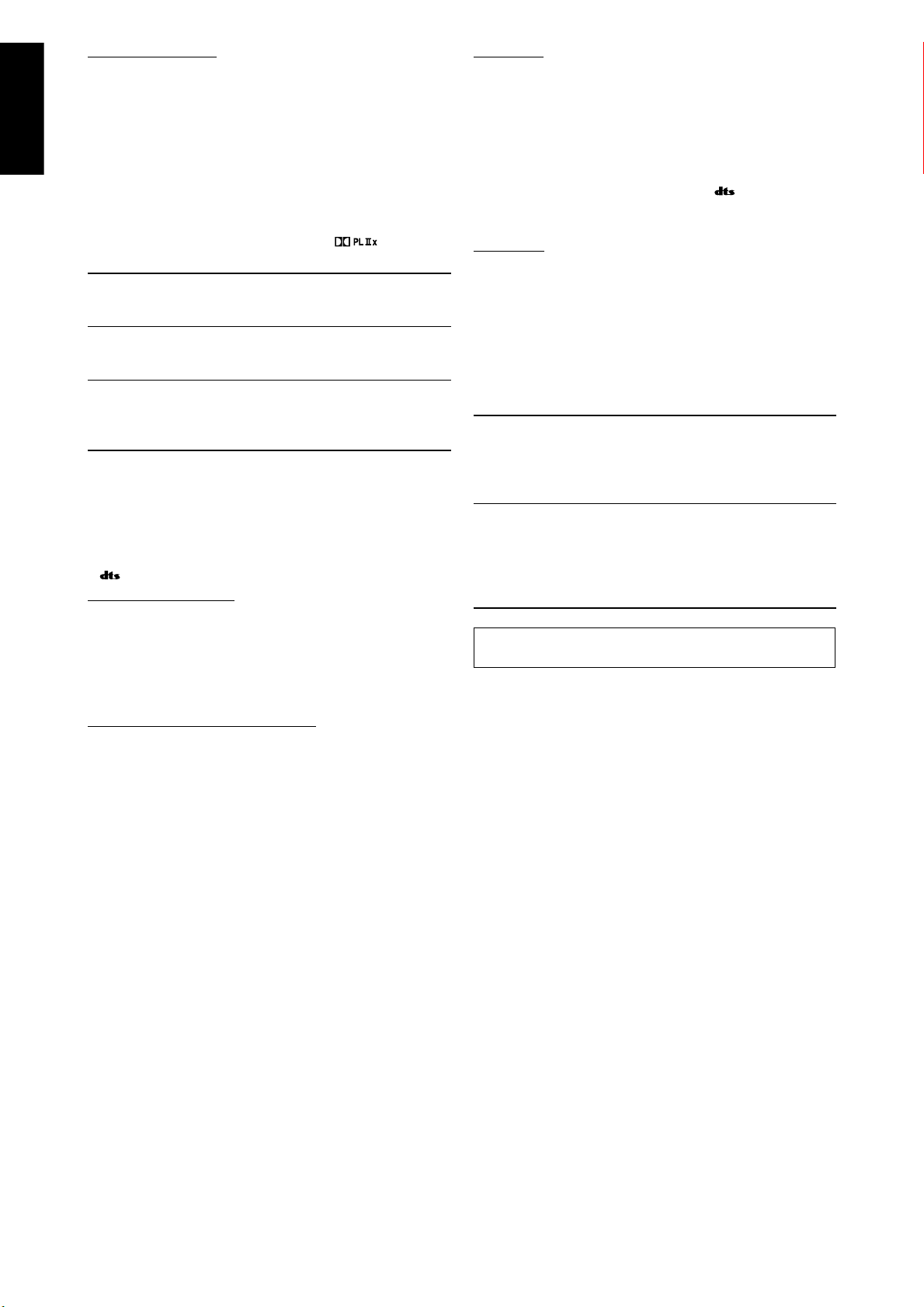
English
Dolby Pro Logic IIx
Dolby Pro Logic IIx is another multi-channel playback
decoder to convert not only multi-channel software but
2-channel software into 7.1 channel (or 6.1 channel) that
developed from Dolby Pro Logic II. The matrix-based
conversion method used for Dolby Pro Logic IIx makes no
limitation for the cutoff frequency of the surround treble.
• This receiver provides three types of Dolby Pro Logic IIx
modes—Pro Logic IIx Movie (PLIIx MOVIE), Pro Logic IIx
Music (PLIIx MUSIC), and Pro Logic IIx Game (PLIIx GAME).
When Dolby Pro Logic IIx is activated, “PLIIx MOVIE,” “PLIIx
MUSIC,” or “PLIIx GAME” appear and the
lights up on the display.
PLIIx MOVIE Suitable for playing any Dolby Surround
encoded software. You can enjoy a sound field
with a natural wraparound effect.
PLIIx MUSIC Suitable for playing any 2-channel stereo
software. You can enjoy wide and deep 7.1channel sounds.
PLIIx GAME Suitable for when playing a video game. You
can enjoy 7.1-channel sounds with “being
there” feeling. This mode is available only for
an analog 2-channel signal.
indicator
7 DTS*
DTS is another digital signal compression method, developed
by Digital Theater Systems, Inc., and enables multi-channel
encoding and decoding (1ch up to 6.1ch).
• When DTS signal is detected through the digital input, the
indicator lights up on the display.
DTS Digital Surround
DTS Digital Surround (DTS) is a discrete 5.1-channel digital
audio format available on CD, LD, and DVD software.
Compared to Dolby Digital, the DTS Digital Surround format
has a lower audio compression rate which enables it to add
breadth and depth to the sounds reproduced. As such, DTS
Digital Surround features natural, solid, and clear sound.
DTS Extended Surround (DTS-ES)
DTS-ES is another multi-channel digital encoding format.
It greatly improves the 360-degree surround impression and
space expression by adding the third surround channel—
surround back channel.
DTS-ES includes two signal formats with different surround
signal recording methods—DTS-ES Discrete 6.1ch (ES
DISCRETE) and DTS-ES Matrix 6.1ch (ES MATRIX).
DTS-ES Discrete 6.1ch has been designed to encode (and
decode) a 6.1-channel signal discretely to avoid interference
with each channel.
DTS-ES Matrix 6.1ch has been designed to add an extra
surround channel to DTS Digital Surround 5.1-channel. By
using a matrix encoding/decoding method, an additional
“surround back” channel signal is encoded (and decoded) in
both the left and right surround channel signals.
DTS 96/24
In recent years, there has been increasing interest in higher
sampling rates both for recording and for reproducing at
home. Higher sampling rates allow wider frequency range and
greater bit depths provide extended dynamic range.
DTS 96/24 is a multi-channel digital signal format (fs 96
kHz/24 bits) introduced by Digital Theater Systems, Inc. to
deliver “better-than-CD sound quality” into the home.
• When DTS 96/24 signal is detected, the
lights up. You can enjoy its 5.1-channel sound with fullquality.
96/24 indicator
DTS Neo:6
DTS Neo:6 is another conversion method to create 6-channel
(plus subwoofer) from analog/digital 2-channel software by
using the high precision digital matrix decoder used for DTSES Matrix 6.1ch.
• This receiver provides the following DTS Neo:6 modes—
Neo:6 Cinema (NEO:6 CINEMA) and Neo:6 Music (NEO:6
MUSIC).
When one of them is activated, the NEO:6 indicator lights up
on the display.
NEO:6 CINEMA Suitable for playing movies. You can get the
same atmosphere with 2-channel software
as with 6.1-channel software. It is also
effective for playing software encoded with
conventional surround formats.
NEO:6 MUSIC Suitable for playing music software. The
front channel signals bypass the decoder
(resulting in no loss of sound quality) and
the surround signals transmitted through
the other speakers expand the sound field
naturally.
* “DTS”, “DTS-ES”, “Neo:6” and “DTS 96/24” are trademarks
of Digital Theater Systems, Inc.
When using Surround mode, the sounds come out of the
activated speakers which the Surround mode requires.
• If either “SURROUND SPK” or “CENTER SPK” is set
to “NO” in the speaker setting (see page 30), the
corresponding channel signals are allocated to and emitted
through the front speakers.
• If both “SURROUND SPK” and “CENTER SPK” are set to
“NO” in the speaker setting (see page 30), JVC’s original
3D-PHONIC processing (which has been developed to create
the surround effect through the front speakers only) is used.
The 3D-PHONIC indicator lights up on the display.
40
Page 43

English
About other digital signals
Linear PCM—Uncompressed digital audio data used for
DVDs, CDs, and Video CDs
DVDs support 2 channels with sampling rates of 48/96 kHz,
at quantization of 16/20/24 bits. On the other hand, CDs
and Video CDs are limited to 2 channels with 44.1 kHz at 16
bits.
• When Linear PCM signal is detected, the LINEAR PCM
indicator lights up.
Multi-channel PCM—Uncompressed multi-channel digital
audio data used for DVD-Audios
DVD-Audios support up to 5.1 channels with sampling rates
of 44.1/48/88.2/96 kHz and 2 channels with sampling rates
of 44.1/48/88.2/96/176/192 kHz, at quantization of 16/20/24
bits.
• When the Multi-channel PCM signal is detected, the
LINEAR PCM indicator lights up and “MULTI CH PCM”
appears on the display for a while.
Dual Mono
Dual Mono can be easily understood when you think of the
bilingual broadcast for TV programs (however, the Dual
Mono format is not identical with those analog formats).
This format is now adopted in Dolby Digital, DTS, and so on.
It allows two independent channels (called main channel
and sub-channel) to be recorded separately.
• You can select either channel you want to listen to (see
page 32).
7 Digital Acoustic Processor (DAP) modes
You can use the following DAP modes in order to reproduce a
more acoustic sound field in your listening room.
HALL1 Reproduces the spatial feeling of a large
shoebox-shaped hall designed primarily for
classical concerts. (Its seating capacity is about
2000.)
HALL2 Reproduces the spatial feeling of a large
vineyard-shaped hall designed primarily for
classical concerts. (Its seating capacity is about
2000.)
LIVE CLUB Reproduces the spatial feeling of a live music
club with a low ceiling.
DANCE CLUB Reproduces the spatial feeling of a rocking
dance club.
PAVILION Reproduces the spatial feeling of an exhibition
hall with a high ceiling.
THEATER1 Reproduces the spatial feeling of a large
theater where the seating capacity is about
600.
THEATER2 Reproduces the spatial feeling of a small
theater where the seating capacity is about
300.
NOTE
When “THEATER1” or “THEATER2” is activated while playing back
2-channel analog or digital source, the built-in Dolby Pro Logic II
decoder is activated and the indicator lights up.
Introducing the DSP modes
The sound heard in a concert hall, club, etc. consists of direct
sound and indirect sound—early reflections and reflections
from behind. Direct sounds reach the listener directly without
any reflection. On the other hand, indirect sounds are delayed
by the distances of the ceiling and walls. These direct sounds
and indirect sounds are the most important elements of the
acoustic surround effects.
The DSP modes can create these important elements, and
give you a real “being there” feeling.
Reflections from behind
Early reflections
Direct sounds
The DSP modes include the following modes:
• Digital Acoustic Processor (DAP) modes—HALL1, HALL2,
LIVE CLUB, DANCE CLUB, PAVILION, THEATER1, THEATER2
• MONO FILM—Used for all types of 2-channel signals
(including Dual Mono signal)
• All Channel Stereo mode (ALL CH STEREO)
When using the DAP mode, the sounds come out of all the
connected and activated speakers.
• If “SURROUND SPK” is set to “NO” in the speaker setting
(see page 30), JVC’s original 3D-PHONIC processing (which
has been developed to create the surround effect through
the front speakers only) is used.
The 3D-PHONIC indicator lights up on the display.
7 MONO FILM
In order to reproduce a more acoustic sound field in your
listening room while viewing monaural sound video software
(analog and 2-channel digital signals including Dual Mono
signal), you can use this mode.
The surround effect will be added, and the sound localization
of actor’s words will be improved.
This mode cannot be used for multi-channel digital
signals.
When “MONO FILM” is used, sounds come out of all the
connected (and activated) speakers.
• If “SURROUND SPK” is set to “NO” in the speaker setting
(see page 30), JVC’s original 3D-PHONIC processing (which
has been developed to create the surround effect through
the front speakers only) is used.
The 3D-PHONIC indicator lights up on the display.
• If incoming signals change from 2-channel digital signal to
another digital signal type, “MONO FILM” is canceled and an
appropriate Surround mode is activated.
When one of the DSP modes is activated, the DSP indicator
lights up on the display.
Continued on the next page
41
Page 44

English
7 All Channel Stereo mode (ALL CH STEREO)
This mode can reproduce a larger stereo sound field using all
the connected (and activated) speakers. This mode cannot
be used if “SURROUND SPK” is set to “NO” in the speaker
setting (see page 30).
3D HEADPHONE mode
If you connect a pair of headphones while one of the
Surround/DSP modes is in use, the 3D HEADPHONE mode
is activated without respect to the type of software played
back.
• “3D HEADPHONE” appears on the display and the DSP
and HEADPHONE indicators light up.
Sound reproduced from
normal stereo
Sound reproduced from
All Channel Stereo mode
Using the Surround/DSP modes
Available Surround/DSP modes vary depending on the speaker settings and the incoming signals. See the table below.
• The numbers inside the parentheses following the incoming signal type indicate the number of the front channels and that of
the surround channels. For example, (3/2) indicates that the signals are encoded with three front signals (left/right/center) and
two (stereo) surround signals.
• For EX/ES/PLIIx setting, see page 32.
Incoming Signal Type
Dolby Digital Surround EX DOLBY D EX*
AUTO ON PLIIx MOVIE PLIIx MUSIC OFF
2, 4
DOLBY D EX*
Dolby Digital (3/2, 2/2) DOLBY DIGITAL DOLBY D EX*
Dolby Digital (3/1, 2/1, 3/0, 1/0) DOLBY DIGITAL
Dolby Digital
Dolby Digital (Dual Mono) DUAL MONO
DTS-ES Discrete DTS-ES DSCRT*2DTS-ES DSCRT*
DTS-ES Matrix
DTS
DTS (3/2, 2/2) DTS SURROUND DTS+NEO:6*
DTS-ES
MATRIX*
2
DTS-ES
MATRIX*
DTS (3/1, 2/1, 3/0, 1/0) DTS
DTS (Dual Mono) DUAL MONO
Analog/LINEAR PCM/Dolby Digital/
DTS (2/0)
EX/ES/PLIIx setting
2
MOVIE*
2
MOVIE*
DTS+PLIIx
2
MOVIE*
DTS+PLIIx
2
2
MOVIE*
DTS+PLIIx
MOVIE*
PLIIx MOVIE*
PLIIx MUSIC*
PLIIx GAME*
3
3
3
NEO:6 CINEMA/
NEO:6 MUSIC
D+PLIIx
1, 2
D+PLIIx
1, 2
1, 2
1, 2
1, 2
/
/
/
D+PLIIx
2
MUSIC*
D+PLIIx
2
MUSIC*
DTS+PLIIx
2
MUSIC*
DTS+PLIIx
2
MUSIC*
DTS+PLIIx
2
MUSIC*
DOLBY DIGITAL
DOLBY DIGITAL
DTS SURROUND
DTS SURROUND
DTS SURROUND
PLII MOVIE/
PLII MUSIC/
PLII GAME/
NEO:6 CINEMA/
NEO:6 MUSIC
1
*
When “S BACK OUT” is set to “1SPK,” “ D+PLIIx MOVIE” is changed to “DOLBY D EX” and “DTS+PLIIx MOVIE” is changed to
“DTS+
2
*
When “S BACK SPK” is set to “NO,” Virtual Surround Back is activated for the modes and the VIRTUAL SB indicator lights up on
EX.”
the display.
3
*
When “S BACK SPK” is set to “NO,” “PLllx MOVIE,” “PLllx MUSIC,” and “PLllx GAME” are changed to “PLll MOVIE,” “PLll MUSIC,”
and “PLll GAME.”
4
*
For some Dolby Digital Surround EX software, Dolby Digital 5.1-channel reproduction (“DOLBY DIGITAL”) may be applied even
though you have selected “AUTO.” Select “ON” to apply “DOLBY D EX.”
42
Page 45

English
7 About the DSP modes
• The following DSP modes are available regardless of
incoming signal type:
HALL1, HALL2, LIVE CLUB, DANCE CLUB, PAVILION,
THEATER1, THEATER2
• If multi-channel (more than 2 channels) digital signals are
coming in, “MONO FILM” is not available.
• If “SURROUND SPK” is set to “NO,” “ALL CH STEREO” is not
available.
Virtual Surround Back
If you have connected (and activated) the surround
speakers, you can use Virtual Surround Back.
This function creates the great surround effect from the
behind without using a surround back speaker as if you
have connected it.
• The VIRTUAL SB indicator lights up on the display.
Virtual Surround Back is activated when selecting any
setting other than “OFF” for the EX/ES/PLIIx setting and
playing back the software including the following signals:
– Dolby Digital Surround EX
– DTS-ES
– Dolby Digital or DTS with 4 channels or more
Activating the Surround/DSP modes
Available Surround/DSP modes vary depending on the
speaker settings and the incoming signals. For details about
the Surround modes, see page 42.
Activating one of the Surround/DSP modes
automatically recalls the memorized settings and
adjustments.
• To adjust the speaker output level, see page 36.
• When activating one of the Surround/DSP modes, you
can adjust the center tone (see page 38).
• When activating one of the Surround/DSP modes
(except PLIIx MUSIC, PLII MUSIC, NEO:6 MUSIC, and
ALL CH STEREO), you can align the vertical localiztion of
the center channel (see page 38).
• When activating “NEO:6 MUSIC,” you can adjust the
sound localization of the center channel (see page 38).
• When activating the DSP mode (except ALL CH
STEREO), you can adjust the following settings:
– Effect level (see page 37)
– Liveness effect (see page 37)
– Virtual room size (see page 37)
• When activating “PLIIx MUSIC” and “PLII MUSIC,” you
can adjust the following settings:
– Center channel localization (see page 38)
– Sound localization position (see page 38)
– Panorama control (see page 37)
7 AUTO SURROUND
You can enjoy the Surround mode easily while playing a
digital source.
• For the Surround/DSP mode seleciton, see page 44.
How does “AUTO SURROUND” work?
• If a multi-channel signal comes in, an appropriate
Surround mode will be selected automatically.
• If a Dolby Digital 2-channel signal with surround signal
comes in, “PLIIx MOVIE” or “PLII MOVIE” will be selected.
• If a Dolby Digital 2-channel signal without surround signal
comes in, “SURROUND OFF (stereo)” will be selected.
• If a Linear PCM signal comes in, “SURROUND OFF (stereo)”
will be selected.
• When “AUTO SURROUND” is activated, the AUTO SURR
indicator lights up on the display.
NOTE
“AUTO SURROUND” does not take effect in the following cases:
– While playing an analog source,
– While selecting one of the fixed digital decode mode—“DOLBY
DIGITAL” or “DTS” (see page 22).
43
Page 46
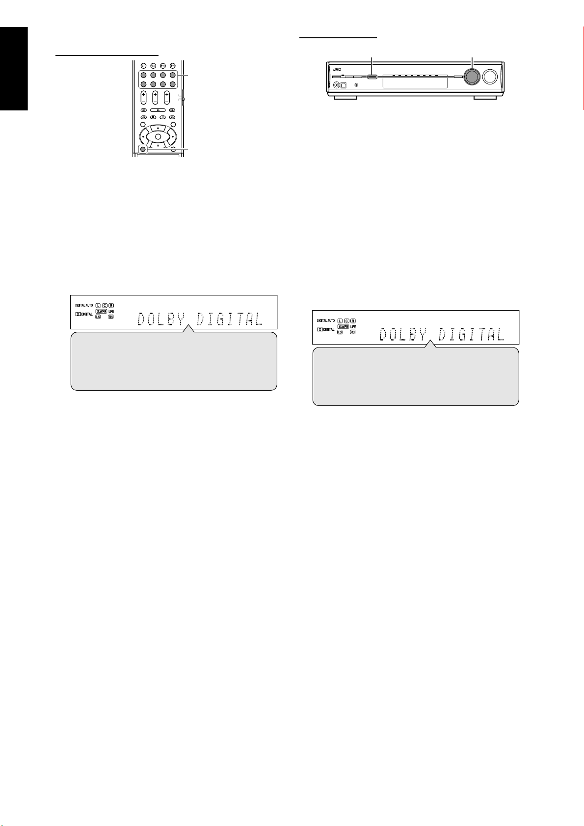
English
7 Selecting the Surround/DSP modes
From the remote control:
1
On the front panel:
1, 32
Before you start, remember...
There is a time limit in doing the following steps. If the setting
is canceled before you finish, start from step
2 again.
2
1 Select and play any source.
• Surround/DSP modes are not available when multichannel PCM (see page 41) signals recorded in DVDAudio are coming in. See page 11 for details.
• Make sure you have selected the audio input setting
(analog or digital) correctly (see page 21).
2 Press SURROUND repeatedly to select
the Surround/DSP mode you want.
Ex.: When “DOLBY DIGITAL” is selected for Dolby Digital
multi-channel software:
AUTO SURROUND*1 = Surround modes*2 = HALL1
= HALL2 = LIVE CLUB = DANCE CLUB = PAVILION
= THEATER1 = THEATER2 = MONO FILM*
ALL CH STEREO*
(Back to the beginning)
1
*
“AUTO SURROUND” is the initial setting.
2
*
Available Surround modes vary depending on the
speaker settings and the incoming signals. For details,
see page 42.
3
*
If an incoming signal is a multi-channel (more than 2
channel) digital signal, “MONO FILM” is not available.
4
*
If “SURROUND SPK” is set to “NO,” “ALL CH STEREO” is
not available.
To cancel Surround/DSP modes
Press SURROUND repeatedly so that “SURROUND OFF”
appears on the display.
4
= SURROUND OFF =
3
=
1 Select and play any source.
• Surround/DSP modes are not available when multichannel PCM (see page 41) signals recorded in DVDAudio are coming. See page 11 for details.
• Make sure you have selected the audio input setting
(analog or digital) correctly (see page 21).
2 Press SURROUND.
MULTI JOG now works for selecting Surround/DSP modes.
3 Turn MULTI JOG to select the Surround/
DSP mode you want.
Ex.: When “DOLBY DIGITAL” is selected for Dolby Digital
multi-channel software:
AUTO SURROUND*1 Ô Surround modes*2 Ô HALL1
Ô HALL2 Ô LIVE CLUB Ô DANCE CLUB Ô
PAVILION Ô THEATER1 Ô THEATER2 Ô MONO
3
FILM*
Ô ALL CH STEREO*4 Ô SURROUND OFF Ô
(Back to the beginning)
1
*
“AUTO SURROUND” is the initial setting.
2
*
Available Surround modes vary depending on the
speaker settings and the incoming signals. For details,
see page 42.
3
*
If an incoming signal is a multi-channel (more than 2
channels) digital signal, “MONO FILM” is not available.
4
*
If “SURROUND SPK” is set to “NO,” “ALL CH STEREO” is
not available.
To cancel Surround/DSP modes
Turn MULTI JOG so that “SURROUND OFF” appears on the
display.
44
Page 47
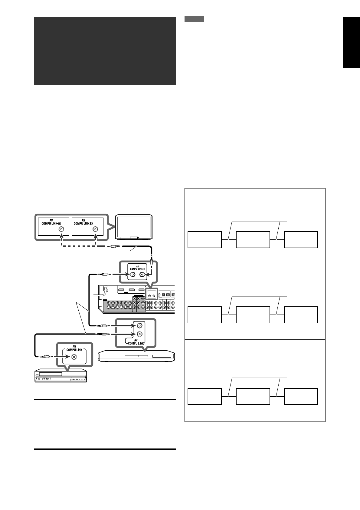
English
AV COMPU LINK
remote control
system
The AV COMPU LINK remote control system allows you to
operate JVC’s video components (TV, DVD player*, and
VCR) through this receiver.
This receiver is equipped with the AV COMPU LINK-III, which
has added a function to operate JVC’s video components
through the component video jacks. To use this remote
control system, you need to connect the video components
you want to operate, following the diagrams below and the
procedures on page 46.
• Refer also to the manuals supplied with your video
components.
* “DVD player” on pages 45 and 46 can be replaced with “DVD
recorder.”
7 Connections 1: AV COMPU LINK connection
TV
NOTES
• When connecting the receiver and a TV with the AV COMPU LINK
EX terminal by using a component video cable, you cannot use
Automatic selection of TV input mode (see page 46).
• When connecting only the VCR or DVD player to this receiver,
connect it directly to the receiver using a cable with the monaural
mini-plugs.
• You can connect only the TV with AV COMPU LINK EX or AV COMPU
LINK-III terminal to the AV COMPU LINK-III terminal.
7 Connections 2: Video cable connection
This receiver is equipped with three types of the video
terminals as well as the HDMI terminals—composite video,
S-video, and component video—and the signals coming into
this receiver through one type of video terminals can output
only through the terminal of the same type. So you need to
connect the video components to this receiver using one of
the following three ways.
• When using the AV COMPU LINK remote control system,
set the video input and video output setting for the DVD
player and the VCR correctly (see “Selecting the video
input setting” on page 21 and “Selecting the output video
signals—VIDEO OUTPUT” on page 34); otherwise, the
correct input for this receiver will not be selected on the TV.
Case 1:
When connecting the source equipment to the receiver
through the S-video terminals, connect this receiver to
the TV video input 1 terminal using S-video cables.
S-video cable
Monaural mini-plugs (not supplied)
Monaural mini-plugs
(not supplied)
DVD player
VCR
IMPORTANT:
• The AV COMPU LINK remote control system cannot control
the DBS tuner connected to the DBS IN jacks.
• To use the AV COMPU LINK remote control system, select
“OTHER” for the video output setting (see page 34);
otherwise, the AV COMPU LINK remote control system is
restricted to turning the video component on and off. See
“Automatic power on/off” on page 46.
Source
equipment
Case 2:
When connecting the source equipment to the receiver
through the composite video jacks, connect this
receiver to the TV video input 2 terminal (composite
video input) using composite video cables.
Source
equipment
Case 3:
When connecting the source equipment to the receiver
through the component video jacks, connect this
receiver to the TV video input 2 terminals (component
video input) using component video cables.
Source
equipment
RX-D412B
RX-D412B
RX-D412B
TV
TV video input 1
Composite
video cable
TV
TV video input 2
(Composite)
Component
video cable
TV
TV video input 2
(Component)
45
Page 48

English
7 Connecting procedure
1
If you have already plugged your VCR,
DVD player, TV, and this receiver into the
AC outlets, unplug their AC power cords
first.
2 Connect your VCR, DVD player, TV, and
this receiver, using the cables with the
monaural mini-plugs (not supplied).
• See “Connections 1” on the previous page.
3 Connect the audio input/output jacks
on the VCR, DVD player, TV, and this
receiver using the audio cables.
• See pages 10 to 13.
4 Connect the video input/output jacks
on the VCR, DVD player, TV, and this
receiver using the S-video cables,
composite video cables, or component
video cables.
• See “Connections 2” on the previous page.
5 Plug the AC power cords of the
connected components and this receiver
into the AC outlets.
One-touch video play
Simply by inserting a video cassette without its safety tab into
the VCR, you can enjoy the video playback without setting
other switches manually. The receiver automatically turns on
and changes the source to “VCR.”
The TV automatically turns on and changes the input mode
to the appropriate position so that you can view the playback
picture.
When you insert a video cassette with its safety tab, press the
play (3) button on the VCR or on the remote control. So, you
can get the same result.
One-touch DVD play
Simply by starting playback on the DVD player, you can enjoy
the DVD playback without setting other switches manually.
The following is set automatically:
• Turning on the receiver.
• Changing the source to “DVR/DVD.”
The TV automatically turns on and changes the input mode
to the appropriate position so that you can view the playback
picture.
Automatic selection of TV input mode
• When you select “TV” as the source to play on the receiver,
the TV automatically changes the input mode to the TV
tuner so that you can watch TV.
• When you select “DVR/DVD,” “VCR,” or “DBS” as the source
to play on the receiver, the TV automatically changes the
input mode to the appropriate position (either video input 1
or video input 2) so that you can view the playback picture.
6 When turning on the TV for the first time
after the AV COMPU LINK connection,
turn the TV volume to the minimum
using the TV volume control on the TV.
7 Turn on the connected components first,
then turn on this receiver.
• When turning on the VCR, use the remote control
supplied with this receiver (press VCR
The AV COMPU LINK remote control system allows you to use
the five basic functions listed below.
Remote control of the TV, DVD player, and VCR using
this remote control
See pages 47 to 51 for details.
• Aim the remote control directly at the remote sensor on
each component.
).
NOTE
This function does not work when you connect this receiver and the
TV with the AV COMPU LINK EX terminal using a component video
cable. In this case, reconnect the TV referring to Case 1 or Case 2 on
page 45.
Automatic power on/off
The TV, DVD player, and VCR turn on and off along with the
receiver.
When you turn on the receiver;
• If the previously selected source is “TV” or “DBS,” only the TV
will turn on automatically.
• If the previously selected source is “DVR/DVD,” the TV and
DVD player will turn on automatically.
• If the previously selected source is “VCR,” the TV and VCR
will turn on automatically.
When you turn off the receiver, the TV, DVD player, and VCR
will turn off.
NOTES
• When “VIDEO OUTPUT” is set to “HDMI” (see page 34), the AV
COMPU LINK remote control system is restricted to turning the
video component on and off.
• If you turn off the receiver while recording on the VCR, the VCR will
not turn off, but continue recording.
46
Page 49

English
Operating other JVC
products
You can use the supplied remote control to operate not
only this receiver but also other JVC products.
• Refer also to the manuals supplied with the other products.
– Some JVC VCRs can accept two types of the control
signals—remote codes “A” and “B.” This remote control
can operate a VCR whose remote control code is set to “A.”
– Some JVC DVD recorders can accept four types of the
control signals. Select an appropriate code for your DVD
recorder (see page 48).
• To operate other products, aim the remote control directly
at the remote sensor on the target product.
7 TV
7 VCR 7 SIRIUS Satellite Radio
You can always perform the following operation:
VCR :
After pressing VCR, you can perform the following operations
on the VCR:
CHANNEL +/–: Change the channel numbers on the VCR.
1 – 9, 0: Select the channel numbers on the VCR.
3: Start playback.
7: Stop playback.
8: Pause playback. To release it, press 3.
¡: Fast-forward a tape.
1: Rewind a tape.
Turn on or off the VCR.
You can always perform the following operations:
TV VOL +/–: Adjust the volume on the TV.
TV/VIDEO: Change the input mode (either video
input or TV tuner) on the TV.
After pressing TV, you can perform the following operations
on the TV:
TV/SIRIUS
CHANNEL +/–: Change the channel numbers.
1 – 9, 0, 100+ (h10): Select the channel numbers.
RETURN (10): Switch between the previous channel
:
Turn on or off the TV.
and the current channel.
After pressing SIRIUS, you can perform the following
operations on the SIRIUS Satellite Radio:
TV/SIRIUS
CHANNEL +/–: Change the channel numbers on the
SELECT: Select a highlighted item on the display
CAT 9/( CAT: Change the category of the program.
MENU: Enter and exit from the Menu Option
DISPLAY: Change the text size on the display of the
1 – 9, 0, BAND: Store or tune in to the preset channel.
MEMORY: Store information on the display of the
DIRECT: Enable access to channels of the SIRIUS
PREV: Return to the previous channel.
NOTE
The remote control may not operate a SIRIUS Satellite Radio properly
if it is not KT-SR2000 (JVC SIRIUS Satellite Radio).
Turn on or off the SIRIUS Satellite Radio.
:
SIRIUS Satellite Radio.
of the SIRIUS Satellite Radio.
screen of the SIRIUS Satellite Radio.
SIRIUS Satellite Radio.
SIRIUS Satellite Radio.
Satellite Radio directly by numeric
buttons.
47
Page 50

English
7 DVD recorder or DVD player
To operate the DVD
recorder, set the mode
selector to “DVR.”
To operate the DVD
player, set the mode
selector to “DVD.”
You can always perform the following operation:
DVR/DVD
After pressing DVR/DVD, you can perform the following
operations on the DVD recorder and DVD player.
3: Start playback.
7: Stop playback.
8: Pause playback. To release it, press 3.
¢: Skip to the beginning of the next chapter.
4: Return to the beginning of the current (or
¡: Fast-forward playback.
1: Fast-reverse playback.
TOP MENU/MENU: Display the menu recorded on discs.
5/∞/3/2: Select an item on the menu screen.
SET: Enter the selected item, channel number,
Turn on or off the DVD recorder or DVD
:
player.
previous) chapter.
chapter/title number, or track number (if
required).
After setting the mode selector correctly, you can perform
the following operations on the DVD recorder or DVD player.
See the manual supplied with the DVD recorder or DVD
player for details.
To change the remote control code for DVD recorder
Some JVC DVD recorders can accept four types of control
signals. You can assign one of the four codes to the remote
control supplied for this receiver to operate your DVD
recorder. For details, refer to the manual supplied with the
DVD recorder.
Initial setting: 3
1 Set the mode selector to “DVR.”
2 Press and hold DVR/DVD .
• Keep the button pressed until step 4 is finished.
3 Press DVR/DVD.
4 Enter the remote control code you want
using the numeric buttons (1 – 4, 0).
EX.: To enter the code “2,” press 0, then 2.
Code for DVR Number to enter
101
202
303
404
Only for DVD recorder operations:
CHANNEL +/–: Change the TV channel numbers on the
DVD recorder.
1 – 9, 0: Select a TV channel number (while
stopped) or a chapter/title number, track
number (while playing back). Press SET to
enter the number.
Only for DVD player operations:
1 – 10, 0, h10: Select a chapter/title number, track
number, menu item, etc.
If these buttons do not function normally, use the
remote control supplied with your DVD recorder or DVD
player. Refer also to the manual supplied with the DVD
recorder or DVD player for details.
5 Release DVR/DVD .
Now, the remote control code has been changed.
48
Page 51

English
Operating other
manufacturers’
products
By changing the transmittable signals, you can use the
supplied remote control to operate other manufacturers’
products.
• Refer also to the manuals supplied with the other products.
• To operate those components with the remote control, first
you need to set the manufacturer codes each for the TV,
VCR, CATV converter, DBS tuner, and DVD player.
• After replacing the batteries of the remote control, set the
manufacturer codes again.
• All the functions may not be assigned to the buttons for
some equipment.
To change the transmittable signals for operating a TV
1 Press and hold TV/SIRIUS .
• Keep the button pressed until step 3 is finished.
2 Press TV.
3 Enter the manufacturer code using the
numeric buttons (1 – 9, 0).
See “Manufacturer codes for TV” on the right.
4 Release TV/SIRIUS .
Now, you can perform the following operations on the TV:
TV VOL +/–: Adjust the volume on the TV.
TV/VIDEO: Change the input mode (either
video input or TV tuner) on the TV.
After pressing TV, you can perform the following
operations on the TV:
TV/SIRIUS
CHANNEL +/–: Change the channel numbers.
1 – 9, 0, 100+ (h10): Select the channel numbers.
:
Turn on or off the TV.
Manufacturer codes for TV:
Manufacturer Codes
JVC 01
Akai 02
Bell+Howell 03
Centurion 04
Coronad 05
Daewoo 06, 07, 08
Emerson 09, 10, 11, 12, 13
Fisher 14
GE•Pana 15, 16
GE•RCA 17
Gold Star 18, 19
Hitachi 20, 21
KTV 22, 23
Magnavox 24
Marantz 25
Mitsubishi 25
Panasonic 26, 27
Philips 24
Pioneer 28
Proscan 29
Quasar 30
Radioshack 31
RCA 02, 17, 32, 33, 34, 35
Samsung 36, 37, 45, 46, 47, 48
Sanyo 14
Sears 38
Sharp 39, 49, 50
Sony 40
Symphonic 41, 42
Toshiba 38
Zenith 43, 44
Initial setting: 01
See the manual supplied with the TV for details.
5 Try to operate your TV by pressing TV/
SIRIUS
Your TV turns on or off when you have entered the correct
code.
If more than one code is listed for your brand of TV, try
each one until the correct one is entered.
.
Manufacturer codes are subject to change without
notice. If they are changed, this remote control cannot
operate the equipment.
49
Page 52

English
To change the transmittable signals for operating a VCR
1 Press and hold VCR .
• Keep the button pressed until step 3 is finished.
2 Press VCR.
3 Enter the manufacturer code using the
numeric buttons (1 – 9, 0).
See “Manufacturer codes for VCR” on the right.
4 Release VCR .
Now, you can perform the following operation on the VCR:
VCR :
After pressing VCR, you can perform the following
operations on the VCR:
CHANNEL +/–: Change the TV channel numbers on
1 – 10, 0, h10: Select the TV channel numbers on
3: Start playback.
7: Stop playback.
8: Pause playback. To release it, press 3.
¡: Fast-forward a tape.
1: Rewind a tape.
See the manual supplied with the VCR for details.
Turn on or off the VCR.
the VCR.
the VCR.
5 Try to operate your VCR by pressing VCR
.
Your VCR turns on or off when you have entered the
correct code.
If more than one code is listed for your brand of VCR, try
each one until the correct one is entered.
Manufacturer codes for VCR:
Manufacturer Codes
JVC 01, 02, 03, 04
Aiwa 05
Akai 06, 07, 08
Bell+Howell 09
Daewoo 10
Emerson 11, 12, 13, 14, 15
Fisher 16, 17, 18, 19
G.E. 20, 21
Go Video 22
Gold Star 23
Go-Video A 24
Go-Video B 25
Hitachi 20, 26
Magnavox 27, 28, 29
Mitsubishi 30, 31, 32, 33
NEC 34, 35
Panasonic 36, 37
Philips 27
RCA 38
Samsung 39, 40, 41
Sanyo 16, 17, 18, 19
Scott 42
Sharp 43, 44
Shintom 45
Sony 46, 47, 48, 49, 50, 51
Symphonic 52
Teknica 53, 54
Toshiba 55
Zenith 56
Initial setting: 01
Manufacturer codes are subject to change without
notice. If they are changed, this remote control cannot
operate the equipment.
50
Page 53

English
To change the transmittable signals for operating a CATV
converter or DBS tuner
To change the transmittable signals for operating a DVD
player
1 Press and hold DBS/CATV .
• Keep the button pressed until step 3 is finished.
2 Press DBS.
3 Enter the manufacturer code using the
numeric buttons (1 – 9, 0).
See “Manufacturer codes for CATV converter” or
“Manufacturer codes for DBS tuner” below.
4 Release DBS/CATV .
Now, you can perform the following operation on the
CATV converter or DBS tuner:
Turn on or off the CATV converter or
DBS/CATV
After pressing DBS, you can perform the following
operations on the CATV converter or DBS tuner:
CHANNEL +/–: Change the channel numbers on the
1 – 10, 0: Select the channel numbers on the
See the manual supplied with the CATV converter or DBS
tuner for details.
:
DBS tuner.
CATV converter or DBS tuner.
CATV converter or DBS tuner.
5 Try to operate your CATV converter or
DBS tuner by pressing DBS/CATV
When your CATV converter or DBS tuner turns on or off,
you have entered the correct code.
.
1 Set the mode selector to “DVD.”
2 Press and hold DVR/DVD .
• Keep the button pressed until step 4 is finished.
3 Press DVR/DVD.
4 Enter the manufacturer code using the
numeric buttons (1 – 9, 0).
See “Manufacturer codes for DVD player” below.
5 Release DVR/DVD .
Now, you can perform the following operations on the
DVD player:
Turn on or off the DVD player.
DVR/DVD
3: Start playback.
¢:
4:
7: Stop playback.
8: Pause playback. To release it, press 3.
MENU: Display the menu recorded on DVD
5/∞/3/2: Select an item on the menu screen.
SET: Enter the selected item.
1 – 9, 0, h10: Select the chapter number.
:
Skip to the beginning of the next
chapter (or fast-forward for some
models).
Return to the beginning of the
current chapter (or fast-reverse for
some models).
VIDEO discs.
If more than one code is listed for your brand of CATV
converter or DBS tuner, try each one until the correct one is
entered.
Manufacturer codes for CATV converter:
Manufacturer Codes
G.I. 01
Gemini 02
Hamlin 03, 04, 05, 06
Jerrold 07, 08, 09, 10, 11, 12, 13, 14, 15
Macom 16, 17, 18
Magnavox 19
Oak 20, 21, 22
Panasonic 23, 24
Philips 25, 26, 27, 28, 29, 30
Pioneer 31, 32
S. Atlanta 33, 34, 35
Samsung 36
Tocom 37
Zenith 38, 39
Manufacturer codes for DBS tuner:
Manufacturer Codes
Echostar 40
G.I. 41
Hitachi 42
Hughes 43
Panasonic 44
Primestar 45
RCA 46
Sony 47
Toshiba 48
Initial setting: 01
See the manual supplied with the DVD player for details.
6 Try to operate your DVD player by
pressing DVR/DVD
Your DVD player turns on or off when you have entered
the correct code.
Manufacturer codes for DVD player:
Manufacturer Codes
JVC 01
Hitachi 02
Kenwood 03, 04
Magnavox 05
Marantz 06
Mitsubishi 07
Onkyo 08, 09
Panasonic 10
Philips 06
Pioneer 11
Proscan 12
RCA 12
Samsung 13
Sony 14
Toshiba 05
Yamaha 15
Zenith 05, 16
Initial setting: 01
NOTE
You cannot use this remote control to operate any manufacturers’
DVD recorders other than JVC’s.
Manufacturer codes are subject to change without
notice. If they are changed, this remote control cannot
operate the equipment.
.
51
Page 54

English
Troubleshooting
Use this chart to help you solve daily operational problems.
If there are any problems you cannot solve, contact your JVC
service center.
For Precise Surround Setup and XM Satellite Radio
operations, see the separated troubleshooting on pages
19 and 28.
PROBLEM POSSIBLE CAUSE SOLUTION
The power does not come on. The power cord is not plugged in. Plug the power cord into an AC outlet.
The receiver turns off (enters
standby mode).
Power
“OVER HEAT” flashes on the
display, then the receiver turns
off.
No sound from speakers. Speaker signal cables are not connected. Check the speaker wiring, then reconnect
Sound from one speaker only. Speaker signal cables are not connected
Sounds are intermittently
distorted by the outside noise
such as a lightning discharge.
Sound and picture
No picture on the TV screen. Either the video input setting or video
HDMI signals do not come on. A video or audio format incompatible
Speakers are overloaded because of high
volume.
Speakers are overloaded because of a
short circuit at the speaker terminals.
The receiver is overloaded because of
high voltage.
The receiver is overloaded because of
high volume or long time usage.
Connections are incorrect. Check the audio connections (see pages
An incorrect source is selected. Select the correct source.
Muting is activated. Press MUTING to cancel the mute (see
An incorrect input mode (analog or
digital) is selected.
properly.
When you use the digital coaxial
connection, the sounds may be
intermittently distorted by the outside
noise such as a lightning discharge but
the sound will be restored automatically.
output setting is incorrect.
with this receiver and/or TV is played.
An HDCP-compatible TV is not
connected.
The receiver failed to recognize HDMIconnected components.
An HDMI cable longer than 5 m is used. Use an HDMI cable shorter than 5 m
1. Stop the playback source.
2. Turn on the receiver again, then turn
the volume down.
Check the speaker wiring. If the speaker
wiring is not short-circuited, contact your
dealer.
Consult your dealer after unplugging the
power cord.
Turn the volume down or turn off the
receiver for a while and turn it on again.
If the receiver turns off soon after doing
solutions above, consult your dealer after
unplugging the power cord.
if necessary (see page 8) after unplugging
the power cord.
9 to 15) after unplugging the power cord.
page 22).
Select the correct input mode (analog or
digital).
Check the speaker wiring and reconnect
if necessary (see page 8) after unplugging
the power cord.
This is not a malfunction.
Select the correct settings (see page 21
or 34).
Check the video or audio format of the
signal to see if it is compatible with this
receiver and/or TV.
Connect an HDCP-compatible TV.
Disconnect the HDMI cable and connect
it again after unplugging the power cord.
to assure stable operation and picture
quality.
52
Page 55

English
PROBLEM POSSIBLE CAUSE SOLUTION
The remote control does not
operate as you intend.
The remote control does not
work.
Remote control
Continuous hiss or buzzing
during FM reception.
FM/AM
Occasional cracking noise during
FM reception.
The remote control is not ready for your
intended operation.
There is an obstruction blocking the
remote sensor on the receiver.
Batteries are weak. Replace batteries.
The mode selector is set to the incorrect
position.
Incoming signal is too weak. Connect an outdoor FM antenna (not
The station is too far away. Select another station.
A wrong antenna is being used. Check with your dealer to be sure you
Antennas are not connected properly. Check the connections.
Ignition noise from automobiles. Move the antenna farther from
Set the mode selector correctly, then
press the corresponding source selecting
button before operation.
Remove the obstruction.
Set the mode selector to the proper
position.
supplied) after unplugging the power
cord, or contact your dealer.
have the correct antenna.
automobile traffic.
53
Page 56

English
Specifications
Designs and specifications are subject to change without
notice.
7 Amplifier
Output Power
At stereo operation:
Front channels: 110 W per channel, min. RMS,
driven into 6 Ω at 20 Hz to 20 kHz
with no more than 0.8% total
harmonic distortion.
At surround operation:
Front channels: 110 W per channel, min. RMS, driven
into 6 Ω at 1 kHz with no more than
0.8% total harmonic distortion.
Center channel:
Surround channels:
Surround back channels:
Audio
Audio Input Sensitivity/Impedance:
DVR/DVD, VCR, DBS, TV:
Audio Input (DIGITAL IN)*:
Coaxial: DIGITAL IN 1(DVR/DVD):
Optical: DIGITAL IN 2(DBS), 3(VCR):
USB: USB
* Corresponding to Linear PCM, Dolby Digital, and
DTS (with sampling frequency—32 kHz, 44.1 kHz, 48
kHz).
Audio Output Level:
DVR, VCR: 300 mV
Signal-to-Noise Ratio (’66 IHF/’78 IHF):
Frequency Response (6 Ω):
Bass Boost: +4 dB ±1 dB at 100 Hz
Equalization (at DSP operation):
Center frequency: 63 Hz, 250 Hz, 1 kHz, 4 kHz,
Control range: ±8 dB
110 W, min. RMS, driven into 6 Ω at
1 kHz, with no more than 0.8% total
harmonic distortion.
110 W per channel, min. RMS, driven
into 6 Ω at 1 kHz, with no more than
0.8% total harmonic distortion.
110 W per channel, min. RMS, driven
into 6 Ω at 1 kHz, with no more than
0.8% total harmonic distortion.
300 mV/47 kΩ
0.5 V(p-p)/75 Ω
–21 dBm to –15 dBm
(660 nm ±30 nm)
80 dB/70 dB
20 Hz to 20 kHz (±1 dB)
16 kHz
Video
Video Input Sensitivity/Impedance:
Composite video: DVR/DVD, VCR, DBS:
1 V(p-p)/75 Ω
S-video: DVR/DVD, VCR, DBS:
Y (luminance):
C (chrominance, burst):
Component: DVR/DVD, VCR(DBS):
Y (luminance):
P
B, PR:
Video Output Level/Impedance:
Composite video: DVR, VCR, MONITOR OUT:
S-video: DVR, VCR, MONITOR OUT:
Y (luminance):
C (chrominance, burst):
Component: MONITOR OUT:
Y (luminance):
B, PR:
P
Synchronization: Negative
1 V(p-p)/75 Ω
0.286 V(p-p)/75 Ω
1 V(p-p)/75 Ω
0.7 V(p-p)/75 Ω
1 V(p-p)/75 Ω
1 V(p-p)/75 Ω
0.286 V(p-p)/75 Ω
1 V(p-p)/75 Ω
0.7 V(p-p)/75 Ω
7 HDMI
HDMI Input (Ver. 1.1): VCR(DBS), DVR/DVD
HDMI Output (Ver. 1.0): MONITOR OUT
7 FM tuner (IHF)
Tuning Range: 87.5 MHz to 108.0 MHz
Usable Sensitivity:
Monaural:
50 dB Quieting Sensitivity:
Monaural:
Stereo:
Stereo Separation at OUT (REC): 35 dB at 1 kHz
12.8 dBf (1.2 μV/75 Ω)
16.0 dBf (1.7 μV/75 Ω)
37.5 dBf (20.5 μV/75 Ω)
7 AM tuner
Tuning Range: 522 kHz to 1 710 kHz
7 General
Power Requirements: AC 120 V , 60 Hz
Power Consumption: 160 W/245 VA (at operation)
1.1 W (in standby mode)
Dimensions (W x H x D): 435 mm x 91.5 mm x 371 mm
Mass: 6.9 kg
54
Page 57

Introduction
Nous vous remercions d’avoir acheté un de nos produits JVC.
Avant d’utiliser cet appareil, veuillez lire attentivement et entièrement ce mode d’emploi afin d’obtenir les meilleures
performances possibles de votre appareil, et conservez ce mode d’emploi à titre de référence.
Technologie DCDi
Caractéristiques
Amplificateur numérique à réaction hybride
Le RX-D412B intègre l’amplificateur numérique à réaction
hybride exclusif de JVC. Des pièces et des dispositifs de haute
qualité et une construction interne spéciale vous garantissent
un son de qualité supérieure.
La technologie DCDi (Directional Correlational Deinterlacing),
mise au point par Faroudja élimine les brèches générées par la
conversion en balayage progressif. Avec la technologie DCDi,
vous pouvez obtenir des images vidéo claires et douces sur
votre écran. Pour les RX-D412B, cette fonction est appliquée
uniquement quand les signaux vidéo analogiques NTSC sont
transmis à l’ampli-tuner.
Compatible avec HDMI*
L’interface HDMI (High-Definition Multimedia Interface)
est l’interface standard pour la prochaine génération de
téléviseurs. En connectant les appareils source, cet amplituner et le téléviseur avec des câble HDMI, les signaux vidéo et
audio numérique (y compris Dolby Digital, DTS) sont transmis
par ces câbles. Vous pouvez transférer le signal vidéo et le
signal audio numérique sans conversion AN/NA, avec une
connexion simple.
Comme le RX-D412B prend en charge HDMI version 1,1, cet
ampli-tuner peut recevoir numériquement 5,1 canaux PCM
avec une fréquence d’échantillonnage de 96 kHz et
2 canaux PCM avec une fréquence d’échantillonnage de
192 kHz. (Ce signaux PCM sont appelés “PCM multicanaux”
dans ce manuel.) Vous pouvez profiter d’un son numérique
dans détérioration. De plus, cet ampli-tuner est compatible
avec HDCP** (Protection du contenu numérique à large bande
passante), et les contenus HDCP peuvent être vus si vous
connectez à ce ampli-tuner un téléviseur compatible HDCP.
* HDMI, le logo HDMI et High-Definition Multimedia Interface
sont des marques de commerce ou des marques déposées
de HDMI Licensing LLC.
** HDCP est l’abréviation de “High-bandwidth Digital Content
Protection” (Protection du contenu numérique à large
bande passante), une technologie de contrôle de la copie
très fiable sous licence de Digital Content Protection, LLC.
DAP 7,1 canaux (Processeur acoustique numérique)
La technologie de simulation de champ sonore permet de
recréer l’ambiance précise d’un cinéma ou d’une salle de
concert existante. Grâce aux performances élevées du DSP
(Processeur de signal numérique) et aux grandes capacités de
mémoire, vous pouvez profiter d’un son Surround 7,1 canaux
en reproduisant une source à 2 canaux ou multicanaux.
Precise Surround Setup
Precise Surround Setup est une nouvelle solution mise au
point par JVC permettant une optimisation rapide, facile et
systématique du son Surround.
En utilisant Precise Surround Setup, vous pouvez profiter des
meilleures performances Surround possibles. Precise Surround
Setup mesure l’environnement d’écoute avec précision avec
les microphones spécialisés de type écouteur et ajuste les
réglages des enceintes automatiquement.
Convertisseur CC (Compression Compensatrice)
Le convertisseur CC élimine les instabilités et les ondulations,
atteignant une réduction radicale de la distorsion numérique
par un traitement des données numériques musicales
par quantification 24 bits–et expansion de la fréquence
d’échantillonnage à 128 kHz (pour les signaux fs 32 kHz)/176,4
kHz (pour les signaux fs 44,1 kHz)/192 kHz (pour les signaux fs
48 kHz). En utilisant le convertisseur CC, vous pouvez obtenir
un champ sonore naturel pour n’importe quelle source.
Technologie K2
La technologie K2 a été conçue pour permettre une
reproduction naturelle du son, atteignant une réduction
radicale de la distorsion numérique et en créant un son
d’ambiance original de haute précision.
Précautions
Sources d’alimentations
• Pour débrancher l’ampli-tuner de la prise murale, tirez
toujours sur la fiche et non pas sur le cordon d’alimentations
secteur.
• Ne manipulez pas le cordon d’alimentation secteur avec les
mains mouillées.
• Si vous n’avez pas l’intention d’utiliser l’ampli-tuner
pendant une période prolongée, débranchez le cordon
d’alimentation secteur de la prise murale.
Ventilation
Les sept amplificateurs à haute puissance intégrés dans cet
amplituner génèrent de la chaleur dans le boîtier.
Pour votre sécurité, respectez les points suivants
attentivement:
• Assurez-vous qu’il y a une ventilation suffisante autour de
l’ampli-tuner. Une mauvaise ventilation pourrait entraîner
une surchauffe et endommager l’ampli-tuner.
• Ne bloquez pas les ouvertures ni les trous de ventilation. (Si
les orifices ou les trous de ventilation sont bloqués par un
journal un tissu, etc., la chaleur peut ne pas être évacuée
correctement de l’appareil.)
Autres
• Si un objet métallique ou un liquide tombait à l’intérieur de
l’ampli-tuner, débranchez-le et consultez votre revendeur
avant d’utiliser l’ampli-tuner à nouveau.
• N’utilisez pas cet ampli-tuner dans une salle de bains ou
dans une pièce avec de l’eau.
• Ne placez aucun récipient rempli d’eau ou d’autres liquides
(tels que des cosmétiques ou des médicaments, des vases
de fleurs, des plantes d’intérieur, des tasses, etc.) sur cet
ampli-tuner.
• Ne démontez pas l’appareil. Il n’y a aucune pièce réparable
par l’utilisateur à l’intérieur.
En cas de problème, débranchez le cordon d’alimentation
secteur et consultez votre revendeur JVC.
1
Page 58

Table des matières
Identification des parties ............................................3
Pour commencer ......................................................... 6
Avant l’installation .............................................................................6
Vérification des accessoires fournis ............................................6
Mise en place des piles dans de la télécommande ...............6
Connexion des antennes ................................................................7
Connexion des enceintes ...............................................................8
Connexion des appareils vidéo ....................................................9
Connexion du cordon d’alimentation ..................................... 14
Connexion USB ................................................................................ 15
Precise Surround Setup ............................................16
Réglage des enceintes automatiquement ............................ 16
Guide de dépannage pour Precise Surround Setup .......... 19
Opérations de base ...................................................20
1 Mise de l’appareil sous tension .......................................... 20
2 Sélection de la source de lecture ...................................... 20
3 Ajustement du volume ......................................................... 21
Sélection des réglages de l’entrée vidéo et audio .............. 21
Sélection du mode de décodage numérique ...................... 22
Coupure temporaire du son .......................................................22
Modification de la luminosité de l’affichage ........................ 22
Mise hors tension de l’appareil avec la minuterie
d’arrêt .......................................................................................... 23
Pour rendre les sons naturels ..................................................... 23
Réglages de base .......................................................29
Éléments des réglages de base ................................................. 29
Procédure de fonctionnement .................................................. 30
Réglage des enceintes .................................................................. 30
Mise en service du réglage EX/ES/PLIIx—EX/ES/PLIIx ....... 32
Sélection du canal principal ou secondaire
—DUAL MONO ........................................................................ 32
Réglage des sons graves .............................................................. 33
Utilisation du mode de minuit—MIDNIGHT MODE ........... 33
Réglage des prises d’entrée numériques (DIGITAL IN)
—DIGITAL IN 1/2/3 ................................................................. 34
Réglage du niveau de retard audio—AUDIO DELAY ......... 34
Sélection de la source pour la prise HDMI et les prises
COMPONENT VIDEO
—HDMI SELECT/CMPNT SELECT .......................................34
Sélection des signaux vidéo de sortie
—VIDEO OUTPUT .................................................................... 34
Ajustements sonores .................................................35
Éléments des réglages de base ................................................. 35
Procédure de fonctionnement .................................................. 35
Ajustement des niveaux de sortie des enceintes ................ 36
Ajustement des courbes d’égalisation
—D EQ 63Hz/250Hz/1kHz/4kHz/16kHz .......................... 36
Reinforcement des graves—BASS BOOST ............................ 37
Atténuation du signal d’entrée—INPUT ATT .......................37
Ajustement des paramètres du son pour les modes
Surround/DSP ........................................................................... 37
Création de champs sonores réalistes .....................39
Reproduction de l’ambiance d’un cinéma ............................39
Introduction des modes Surround ........................................... 39
Introduction des modes DSP ...................................................... 41
Utilisation des modes Surround/DSP ...................................... 42
Mise en service des modes Surround/DSP ............................ 43
Système de commande à distance
AV COMPU LINK .....................................................45
Fonctionnement du tuner FM/AM ...........................24
Accord manuel des stations ....................................................... 24
Utilisation de l’accord par préréglage ..................................... 24
Sélection du mode de réception FM .......................................25
Fonctionnement de la radio satellite XM ................26
Préparations ..................................................................................... 26
Écoute de la radio satellite XM ................................................... 26
Utilisation de l’accord par préréglage ..................................... 27
Changement des informations des canaux .......................... 28
Commande d’autres appareils JVC ..........................47
Commande d’appareils d’autres fabricants ............49
Guide de dépannage .................................................52
Spécifications .............................................................54
2
Page 59

Identification des
parties
Pour ouvrir le couvercle de
la télécommande, poussez
ici puis faites glisser le
couvercle vers le bas.
7 Télécommande
Référez-vous aux pages entre parenthèses pour plus de
détails.
1 Touche MUTING (22)
2 Touches attente/mise sous tension (16, 20, 47 – 51)
AUDIO, DVR/DVD , VCR , DBS/CATV ,
TV/SIRIUS
3 Touches de sélection de source (20, 24, 26, 47 – 51)
DVR/DVD, VCR, DBS, TV, USB, XM, FM/AM, SIRIUS
4 Touche TV VOL (volume) +/– (47, 49)
5 Touche CHANNEL +/– (27, 47 – 51)
6 • Touches de commande des appareils vidéo (47 – 51)
4, 3, ¢, 1, 7, 8, ¡
• Touches de commande du tuner FM/AM (24)
( TUNING, TUNING 9
• Touches de fonctionnement de la radio satellite XM ou
de la radio satellite SIRIUS (27, 47)
SELECT*, ( CAT, CAT 9
7 Touches de fonctionnement pour le enregistreur de DVD
ou l’lecteur de DVD** (48, 51)
TOP MENU, MENU, touches de curseur (3, 2, 5, ∞), SET
8 Touche SURROUND (44)
9 Touche TV/VIDEO (47, 49)
p Touche VIDEO INPUT (21)
q Touche AUDIO INPUT (21)
w Touche CC CONVERTER (23)
e Touches de réglage pour l’égaliseur numérique (36)
D.EQ FREQ, D.EQ LEVEL +/–
r Touche DECODE (22)
t Touches de réglage pour le niveau de sortie des enceintes
et du caisson de grave (36)
FRONT L +/–, FRONT R +/–, CENTER +/–, SUBWFR +/–, SURR
L +/–, SURR R +/–, S.BACK L +/–, S.BACK R +/–
y Touche VOLUME +/– (21)
u Sélecteur de mode (48, 51)
i Touche DISPLAY (28, 47)
o • Touches numériques (25, 27, 47 – 51)
1 – 10, 0, h10, +10/100+
• Touche RETURN (47)
; Touche BAND* (47)
a Touche PREV*/FM MODE (25 ,47)
s Touche DIRECT (27)
d Touche DIMMER (22)
f Touche MEMORY (24, 27)
g Touche PSS (Precise Surround Setup) (17)
h Touche TEST (18, 36)
j Touche SLEEP (23)
* Pour la radio satellite SIRIUS uniquement
** Ces touches peuvent être utilisées pour commander un
enregistreur de DVD (appareil JVC uniquement) ou un
lecteur de DVD quand le sélecteur de mode est réglé sur
“DVR” ou “DVD” (voir page 48).
Si ces touches ne fonctionnent pas normalement, utilisez la
télécommande fournie avec votre enregistreur de DVD ou
lecteur de DVD. Référez-vous aussi au manuel fourni avec
l’enregistreur de DVD ou le lecteur de DVD pour plus de
détails.
• Lors de l’utilisation d’un enregistreur de DVD (pour
les appareil JVC uniquement), réglez le sélecteur de
mode (u) sur “DVR”.
• Pour commander le lecteur de DVD, réglez le
sélecteur de mode (u) sur “DVD”.
3
Page 60

Référez-vous aux pages entre parenthèses pour plus de détails.
Panneau avant
1
Touche
2 Touche CC CONVERTER (23)
3 Touche SETTING (30)
4 Touche ADJUST (35)
5 Touche SURROUND (44)
6 Témoin HDMI (9, 21)
7 Témoins de source
DVR/DVD, VCR, DBS, TV/SIRIUS, USB, XM, FM/AM
STANDBY/ON et témoin d’attente (16, 20)
8 • Touche SET (20, 30, 35)
• Touche TUNER PRESET (25, 28)
9 • SOURCE SELECTOR (20, 25, 26)
• MULTI JOG (25, 28, 30, 35, 44)
p Réglage MASTER VOLUME (21)
q Prise PHONES (21)
w Prise USB (15)
e Prise PRECISE SURROUND SETUP MIC (16)
r Fenêtre d’affichage (voir ci-dessous)
t Capateur de télécommande (6)
Fenêtre d’affichage
1 Indicateur ANALOG (21)
2 Indicateur DUAL MONO (32)
3 Indicateur AUTO SURR (surround) (43)
4 Indicateur HEADPHONE (21, 42)
5 Indicateur PSS (Precise Surround Setup) (17)
6 Indicateurs CC CONVERTER 1 et CC CONVERTER 2 (23)
7 Indicateurs de fonctionnement du tuner FM/AM (24)
TUNED, STEREO
8 Indicateur DIGITAL EQ (36)
9 Indicateur AUTO MUTING (25)
0 Indicateur C.TONE (tonalité centrale) (38)
- Indicateur INPUT ATT (atténuation) (37)
= Indicateur SLEEP (23)
~ Indicateurs de format du signal numerique (21, 22, 40, 41)
DIGITAL AUTO, LINEAR PCM,
! Indicateurs de signal et d’enceinte (23)
@ Indicateur NEO:6 (40)
# Indicateur VIRTUAL SB (Surround arrière) (43)
$ Indicateur 3D-PHONIC (40, 41)
% Indicateur DSP (41)
^
Indicateurs
& Affichage principal
* Indicateur B.BOOST (accentuation des graves) (37)
( Indicateur MIDNIGHT (33)
) Indicateurs d’unité de fréquence
MHz (pour les stations FM), kHz (pour les stations AM)
et (39 – 41)
, , 96/24
4
Page 61

Référez-vous aux pages entre parenthèses pour plus de détails.
Panneau arrière
1 Cordon d’alimentation (14)
2 Prises HDMI (9)
VCR(DBS) IN, DVR/DVD IN, MONITOR OUT
3 Prises AV COMPU LINK-III (45)
4 Prises DIGITAL IN (14)
• Coaxiale: 1(DVR/DVD)
• Optique: 2(DBS)
• Optique: 3(VCR)
5 Prise DIGITAL OUT (14)
6 Prise XM (7)
7 Prises FM/AM ANTENNA (7)
8 Prises VIDEO (10 – 13)
Prises VIDEO (vidéo composite), prises S-VIDEO
• Entrée: DBS IN, VCR IN(PLAY), DVR/DVD IN(PLAY)
• Sortie: VCR OUT(REC), DVR OUT(REC), MONITOR OUT
9 Prises COMPONENT VIDEO (Y, P
VCR(DBS) IN, DVR/DVD IN, MONITOR OUT
p Prises AUDIO (10 – 13)
• Entrée: TV/SIRIUS IN, DBS IN, VCR IN(PLAY), DVR/DVD
IN(PLAY)
• Sortie: VCR OUT(REC), DVR OUT(REC)
q Prises DVD MULTI IN (11)
CENTER, SUBWOOFER, SURR–L, SURR–R
w Prise SUBWOOFER OUT (8)
e Prises d’enceinte (8)
SURROUND BACK SPEAKERS, SURROUND SPEAKERS,
CENTER SPEAKER, FRONT SPEAKERS
B, PR) (10 – 13)
5
Page 62

Pour commencer
Mise en place des piles dans de la
télécommande
123
Avant l’installation
7 Précautions générales
• Assurez-vous d’avoir les mains sèches.
• Mettez tous les appareils hors tension.
• Lisez les modes d’emploi fournis avec les appareils qui
doivent être connectés.
7 Emplacement
• Installez l’ampli-tuner dans un endroit plat et protégé de
l’humidité et de la poussière.
• La température autour de l’ampli-tuner doit être comprise
entre –5 °C et 35 °C.
• Assurez-vous qu’il y a une ventilation suffisante autour de
l’ampli-tuner. Une mauvaise ventilation peut entraîner une
surchauffe et endommager l’ampli-tuner.
• Laissez suffisamment d’espace entre l’ampli-tuner et le
téléviseur.
7 Manipulation de l’ampli-tuner
• N’insérez aucun objet métallique à l’intérieur de l’amplituner.
• Ne démontez pas l’ampli-tuner ni ne retirez les vis, les
couvercles ou le compartiment.
• N’exposez pas l’appareil à la pluie ou à l’humidité.
• Ne tirez pas directement sur le cordon d’alimentation. Pour
le débrancher, tenez-le toujours par la fiche de façon à ne
pas endommager le cordon.
• Quand vous êtes en voyage ou absent pendant une période
prolongée, retirez la fiche de la prise secteur murale. Une
faible quantité d’énergie est toujours consommée quand le
cordon d’alimentation est branché à la prise secteur murale.
L’ampli-tuner a un ventilateur de refroidissement
intégré qui fonctionne quand l’appareil est sous
tension. Assurez-vous de laisser un espace suffisant
pour la ventilation afin d’obtenir un effet de
refroidissement satisfaisant.
Avant d’utiliser la télécommande, mettez en place les deux
piles fournies.
1 Faites pression sur le couvercle du
compartiment à piles à l’arrière de la
télécommande et faites le glisser pour le
retirer.
2 Insérez les piles.
Respectez les polarités: (+) à (+) et (–) à (–).
3 Remettez le couvercle en place.
Si la plage de fonctionnement de la télécommande diminue,
remplacez les piles. Utilisez deux piles sèches de type
R6(SUM-3)/AA(15F).
• Les piles fournies ne sont que les pour les réglages initiaux.
Remplacez-les pour continuer d’utiliser l’appareil.
ATTENTION:
Suivez ces précautions pour éviter toute fuite ou fissure des
piles:
• Placez les piles dans la télécommande en respectant leurs
polarités: (+) à (+) et (–) à (–).
• Utilisez des piles de type correct. Des piles ayant l’air
similaires peuvent avoir une tension différente.
• Remplacez toujours les deux pile en même temps.
• N’exposez pas les piles à la chaleur ou à une flamme.
Lors de l’utilisation de la télécommande, dirigez celle-ci
directement vers le capteur de télécommande de panneau
avant.
Capteur de télécommande
ATTENTION:
Ne branchez pas le cordon d’alimentation secteur avant
d’avoir effectué toutes les autres connexions.
Vérification des accessoires fournis
Vérifiez que vous avez bien tous les accessoires fournis
suivants. Si quelque chose manquait, appelez votre revendeur
immédiatement.
• Télécommande (× 1)
• Piles (× 2)
• Antenne cadre AM (× 1)
• Antenne FM (× 1)
• Microphones spécialisés de type écouteur (× 1)
6
Page 63
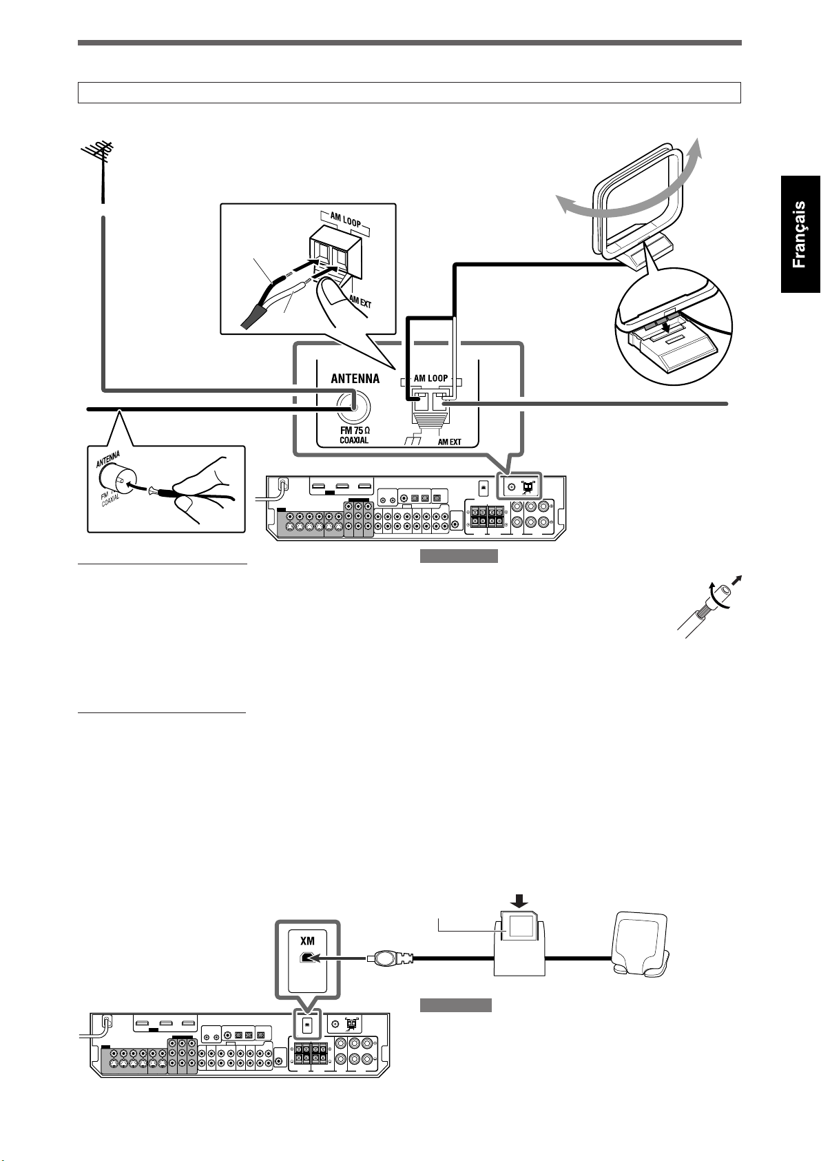
Connexion des antennes
Ne branchez pas le cordon d’alimentation secteur avant d’avoir effectué toutes les autres connexions.
7 Connexion des antennes FM et AM
connectez une antenne FM extérieure
(non fourni).
Noir
Blanc
Antenne cadre AM (fourni)Si la réception FM est mauvaise,
Insérez les languettes du
cadre dans les fentes de
la base pour assembler
l’antenne cadre AM.
Antenne FM (fourni)
Connexion de l’antenne AM
Connectez l’antenne cadre AM (fourni) aux prises AM LOOP:
Connectez le cordon blanc à la prise AM EXT et le cordon noir
à la prise H.
Tournez l’antenne cadre jusqu’à ce que vous obteniez la
meilleure réception possible.
• Si la réception est mauvaise, connectez un fil extérieur
recouvert de vinyle (non fourni) à la prise AM EXT. Laissez
l’antenne cadre AM connectée.
Connexion de l’antenne FM
Connectez provisoirement l’antenne FM fournie à la prise FM
75 Ω COAXIAL.
Tirez sur l’antenne FM fournie à l’horizontale.
• Si la réception est mauvaise, connectez une antenne FM
extérieure (non fourni). Avant de brancher le câble coaxial
75 Ω avec connecteur, déconnectez l’antenne FM fournie.
Si la réception AM est mauvaise,
connectez un fil extérieur recouvert
de vinyle (non fourni).
REMARQUES
• Si l’antenne cadre AM est recouverte de vinyle,
retirez le vinyle en tordant de la façon montrée à
droite.
• Assurez-vous que les conducteurs d’antenne
ne touchent aucunes autres prises, cordons
de connexion ou cordon d’alimentation. Cela
pourrait entraîner une mauvaise réception.
7 Connexion du système de minisyntoniseur XM (minisyntoniseur XM et station d’accueil pour la
maison du minisyntoniseur XM)*
Pour écouter la radio satellite XM, connectez le système de minisyntoniseur XM (non fourni) à cet ampli-tuner.
* Vous pouvez aussi utiliser l’antenne conventionnelle “XM Connect and Play Digital Antenna” (non fournie) pour l’ampli-tuner.
Minisyntoniseur XM (non fourni)
Station d’accueil pour la maison du minisyntoniseur XM (non fourni)
REMARQUE
Pour une meilleure réception:
– Placez l’antenne de la station d’accueil pour la maison du
minisyntoniseur XM près d’une fenêtre dirigée vers le sud ou dans
un endroit où le canal 1 (“Channel 1”) peut être entendu clairement
(voir page 26).
– Assurez-vous qu’il n’y a pas d’obstacle entre l’antenne de la station
d’accueil pour la maison du minisyntoniseur XM et le ciel.
7
Page 64

Connexion des enceintes
Ne branchez pas le cordon d’alimentation secteur avant d’avoir effectué toutes les autres connexions.
7 Schéma de disposition des enceintes
Caisson de grave
SW
actif (SW)
Enceinte surround
arrière gauche (SBL)*
FL
SL
ATTENTION:
• Utilisez des enceintes avec l’impédance d’enceinte
(SPEAKER IMPEDANCE) indiquée sur les prises d’enceintes
(6 Ω – 16 Ω).
• NE CONNECTEZ PAS plusieurs enceintes à la même prise
d’enceinte.
CFR
SR
SBRSBL (SB*)
Enceinte surround
arrière droite (SBR)
Enceinte surround droite (SR)
Enceinte surround gauche (SL)
7 Connexion des enceintes
Mettez tous les appareils hors tension avant de réaliser
les connexions.
Pour connecter l’enceinte centrale et des enceintes avant
12 43
Enceinte centrale (C)
Enceinte
avant
droite (R)
Pour connecter les enceintes surround et les enceintes
Surround arrière
Enceinte
avant
gauche (L)
12 3
1 Coupez, tordez et retirez l’isolant à
l’extrémité de chaque cordon d’enceinte.
2 Ourver la prise (1), et insérer le cordon
d’enceinte (2).
• Pour chaque enceinte, connectez les prises (+) et (–)
du panneau arrière aux prises (+) et (–) des enceintes
respectives.
1 Coupez, tordez et retirez l’isolant à
l’extrémité de chaque cordon d’enceinte.
2 Tournez la prise dans le sens contraire
des aiguilles d’une montre.
3 Insérez le cordon d’enceinte.
• Pour chaque enceinte, connectez les prises (+) et (–)
du panneau arrière aux prises (+) et (–) des enceintes
respectives.
4 Tournez la prise dans le sens des aiguilles
d’une montre.
8
3 Refermer la prise.
* Lors de l’utilisation d’une seule enceinte pour le
surround arrière
Vous pouvez profiter du son Surround avec une seule
enceinte surround arrière. Lors de l’utilisation d’une seule
enceinte surround arrière,
– réglez “S BACK OUT” sur “1SPK” (voir page 31) et
– connectez l’enceinte surround arrière à la prise de
l’enceinte surround arrière gauche. (Aucun son ne
sort de l’enceinte si vous la connectez à la prise de
l’enceinte surround arrière droite.)
7 Connexion du caisson de grave actif
En connectant un caisson de grave vous pouvez améliorer
les graves et reproduire les signaux LFE originaux enregistrés
dans la source numérique.
Connectez la prise d’entrée d’un caisson de grave actif à la
prise SUBWOOFER OUT sur le panneau arrière en utilisant
un câble à fiches cinch (non fourni).
• Référez-vous aussi au mode d’emploi fourni avec votre
caisson de grave.
Après avoir connecté toutes les enceintes et/ou le caisson
de grave, réalisez Precise Surround Setup pour effectuer le
réglage des enceintes automatiquement (voir pages 16 à 19).
REMARQUE
Vous pouvez placer le caisson de grave à l’endroit que vous voulez
puisque les sons graves ne sont pas directionnels. Normalement,
placez-le devant vous.
Page 65

Connexion des appareils vidéo
Ne branchez pas le cordon d’alimentation secteur avant d’avoir effectué toutes les autres connexions.
7 Connexion HDMI
IMPORTANT:
Les signaux HDMI des prises HDMI sont transmis uniquement par la prise HDMI MONITOR OUT.
Par conséquent, vous ne pouvez pas voir l’image de lecture sur le téléviseur:
– quand le téléviseur est connecté à l’ampli-tuner par la prise VIDEO (MONITOR OUT), la prise S-VIDEO (MONITOR OUT), ou les
prises COMPONENT VIDEO (MONITOR OUT) et
– de même quand un appareil de lecture vidéo est connecté à l’ampli-tuner par la prise HDMI—VCR(DBS) IN ou DVR/DVD IN.
Mettez tous les appareils hors tension avant de réaliser les connexions.
• Lors de la connexion des appareils, référez-vous aussi à leur mode d’emploi.
Enregistreur de
DVD ou lecteur
de DVD
Câbles HDMI
(non fourni)
Téléviseur
Magnétoscope
(ou tuner DBS)
Conversion de signaux vidéo en signaux HDMI
Cet ampli-tuner peut convertir les signaux vidéo composites, S-vidéo et en composantes en signaux HDMI et transmettre
les signaux convertis par la prise HDMI MONITOR OUT. Pour utiliser cette fonction, vous devez d’abord réaliser la procédure
suivante:
1 Raccordez le téléviseur à cet ampli-tuner avec le câble HDMI.
2 Réglez la sortie vidéo (voir page 34) sur “HDMI”.
3 Réglez l’entrée vidéo (voir page 21) en fonction de la méthode de connexion de chaque appareil vidéo.
REMARQUES
• Lors de la lecture d’un signal audio et vidéo avec la connexion HDMI, le témoin HDMI sur le panneau est allumé.
• Choisissez “HDMI” pour le réglage de l’entrée vidéo (voir page 21) pour écouter le son à travers la connexion HDMI.
• Quand les signaux vidéo entrés sont convertis en signaux HDMI, l’image de lecture peut être déformée quand vous changez le mode de
lecture (avance rapide, retour rapide ou pause, par exemple).
• Lors de la connexion d’un magnétoscope ou d’un tuner DBS à la prise HDMI VCR(DBS) IN, réglez correctement le réglage HDMI (voir page 34)
en fonction de l’appareil connecté. Si vous ne le faites pas, vous ne pouvez pas voir l’image de lecture sur le téléviseur.
• En utilisant un câble de conversion HDMI-DVI, vous pouvez connecter des appareils source ou un téléviseur muni d’une sortie DVI. Lors de la
connexion de tels appareils ou d’un tel téléviseur, changez le réglage de l’entrée audio sur autre chose que “HDMI”. (Voir page 21.)
• Cet ampli-tuner est compatible avec les formats vidéo standards. Si un format vidéo non standard est entré, l’image peut ne pas apparaître
correctement sur le téléviseur.
• L’image sur le téléviseur peut ne pas avoir le même format que le format réglé sur les appareils source.
• HDMI (High-Definition Multimedia Interface) est une interface qui permet de transmettre les signaux audio et vidéo numérique avec un seul
câble. Cependant, lors de la connexion d’un téléviseur à cet ampli-tuner avec un câble HDMI, le son entrant dans cet ampli-tuner n’est pas
transmis aux enceintes du téléviseur. Vous pouvez sortir le son uniquement des enceintes connectées à cet ampli-tuner.
• Lors de la connexion d’un téléviseur à l’ampli-tuner avec un câble HDMI, les opérations suivantes peuvent causer du bruit ou couper le son et
l’image:
– Mettre un appareil source sous ou hors tension
– Changer fréquemment le réglage de l’entrée audio ou vidéo de cet ampli-tuner
Dans ce cas, mettez l’ampli-tuner hors tension puis de nouveau sous tension.
• Quand vous écoutez un son PCM multicanaux et sélectionnez “HDMI” pour le réglage de l’entrée audio (voir page 21), certaines fonctions ne
sont pas disponibles. Référez-vous à la page 11 pour les détails.
• Quand vous profiter d’un contenu HDCP, le son et l’image peuvent ne pas être transmis aux enceintes et au téléviseur pendant les quelques
secondes du début nécessaires pour la confirmation.
9
Page 66

7 Connexion audio/vidéo
En plus des prises HDMI, cet ampli-tuner est muni de trois
prises vidéo—prise vidéo composite, prise S-vidéo et prises
vidéo en composantes—de prises d’entrée audio analogiques
discrètes 5,1 canaux (DVD MULTI IN) et de prises audio stéréo.
• Si vos appareils vidéo possèdent des prises S-vidéo
(séparation Y/C) et/ou vidéo en composantes (Y, P
B, PR)
connectez-les en utilisant un câble S-vidéo (non fourni) ou
un câble vidéo en composantes (non fourni). En utilisant ces
prises, vous pouvez obtenir une image de meilleure qualité
dans l’ordre suivant:
Composantes > S-vidéo > Composite
IMPORTANT:
Les signaux vidéo d’un type de ces prises d’entrée sont
transmis uniquement par les prises vidéo du même type.
Par conséquent, si un appareil vidéo d’enregistrement et
un appareil vidéo de lecture sont connectés à l’ampli-tuner
par les prises vidéo de type différent, vous ne pouvez pas
enregistrer l’image. De plus, si le téléviseur et l’appareil vidéo
de lecture sont connectés à l’ampli-tuner par des prises vidéo
de type différent, vous ne pouvez pas voir l’image de lecture
sur le téléviseur.*
Ne branchez pas le cordon d’alimentation secteur avant d’avoir effectué toutes les autres connexions.
Connexion d’un enregistreur de DVD ou d’un lecteur de DVD par ses prises de sortie stéréo:
N’UTILISEZ PAS un téléviseur connecté à travers un
magnétoscope ou un téléviseur avec un magnétoscope
intégré; l’image pourrait être déformée.
ATTENTION:
Si vous connectez un appareil d’amélioration du son tel qu’un
égaliseur graphique entre l’appareil source et cet appareil, la
sortie sonore à travers cet appareil risque d’être déformée.
Si votre appareil vidéo est muni de prises AV COMPU LINK
Référez-vous aussi à la page 45 pour des informations
détaillées sur sa connexion et le système de commande à
distance AV COMPU LINK.
* Quand vous connectez le téléviseur à l’ampli-tuner par
la prise HDMI MONITOR OUT et choisissez “HDMI” pour
le réglage de la sortie vidéo, vous pouvez voir l’image de
lecture sur le téléviseur.
Mettez tous les appareils hors tension avant de réaliser les connexions.
• Lors de la connexion des appareils, référez-vous aussi à leur mode d’emploi.
Vert
Bleu
Câble vidéo en composantes (non fourni)
Rouge
Blanc
Rouge
Rouge
Blanc
Câble audio stéréo
(non fourni)
Câble vidéo composite
(non fourni)
Câble S-vidéo (non fourni)
: flux du signal
Enregistreur de DVD ou lecteur
de DVD
Câble vidéo composite (non fourni)
REMARQUES
• Choisissez le réglage de l’entrée audio et vidéo en fonction de la
méthode de connexion. Référez-vous à la page 21 pour les détails.
• Vous pouvez profiter d’un son numérique en utilisant un câble
numérique coaxial ou optique. À l’expédition de l’usine, la prise
coaxiale numérique—DIGITAL IN 1(DVR/DVD) à l’arrière de l’amplituner est réglée pour un enregistreur de DVD et un lecteur de DVD.
Pour en savoir plus sur la connexion audio numérique, référez-vous
à la page 14.
10
Å À la sortie vidéo en composantes
• Connectez Y, P
B, et PR correctement.
ı À la sortie du canal audio gauche/droit
Ç Uniquement pour l’enregistreur de DVD: À l’entrée du
canal audio gauche/droit
Î À la sortie vidéo composite
‰ À la sortie S-vidéo
Ï Uniquement pour l’enregistreur de DVD: À l’entrée
S-vidéo
Ì Uniquement pour l’enregistreur de DVD: À l’entrée
vidéo composite
Page 67

Ne branchez pas le cordon d’alimentation secteur avant d’avoir effectué toutes les autres connexions.
Connexion d’un enregistreur de DVD ou d’un lecteur de DVD par ses prises de sortie analogiques discrètes
(DVD MULTI IN):
Si votre enregistreur de DVD ou lecteur de DVD possède des prises de sortie analogiques à 5,1 canaux, utilisez la connexion cidessous. Quand un disque DVD-Audio est reproduit, les sons originaux multicanaux de haute qualité peuvent être reproduits en
utilisant cette connexion.
Mettez tous les appareils hors tension avant de réaliser les connexions.
• Lors de la connexion des appareils, référez-vous aussi à leur mode d’emploi.
Vert
Bleu
Rouge
Câble S-vidéo (non fourni)
Câble vidéo composite (non fourni)
Câble vidéo en composantes (non fourni)
Câble audio monophonique (non fourni)
Blanc
Rouge
Câble audio stéréo
(non fourni)
Câble audio
monophonique
(non fourni)
Blanc
Rouge
Rouge
Blanc
Câble audio stéréo
(non fourni)
Câble vidéo composite
(non fourni)
: flux du signal
Enregistreur de DVD
ou lecteur de DVD
À la sortie audio du canal surround gauche/droit
Å
À la sortie audio du canal central
ı
À la sortie vidéo en composantes
Ç
• Connectez Y, P
À la sortie du caisson de grave
Î
À la sortie audio du canal avant gauche/droit
‰
B, et PR correctement.
Quand vous écouter un son enregistré en DVD-Audio...
Vous pouvez écouter un son enregistré en DVD-Audio avec
la méthode analogique ou numérique.
– Avec la méthode analogique:
1. Connectez votre enregistreur de DVD ou lecteur de DVD
à cet ampli-tuner en fonction de l’illustration ci-dessus.
2. Choisissez “A MULTI” pour le réglage de l’entrée audio.
(Voir page 21.)
– Avec la méthode numérique:
1. Connectez votre enregistreur de DVD ou lecteur de DVD
et le téléviseur à l’ampli-tuner avec les câble HDMI. (Voir
page 9.)
2. Choisissez “HDMI” pour le réglage de l’entrée audio.
(Voir page 21.)
Uniquement pour l’enregistreur de DVD: À l’entrée
Ï
audio du canal avant gauche/droit
À la sortie vidéo composite
Ì
À la sortie S-vidéo
Ó
Uniquement pour l’enregistreur de DVD: À l’entrée
È
S-vidéo
Uniquement pour l’enregistreur de DVD: À l’entrée
Ô
vidéo composite
REMARQUES
• Quand “A MULTI” est choisi pour le réglage de l’entrée audio et
que vous utilisez un casque d’écoute, vous pouvez uniquement
écouter le son des canaux avant (gauche et droit). Le mode 3D
HEADPHONE (voir page 42) n’est pas disponible.
• Quand “A MULTI” est choisi pour le réglage d’entrée audio ou
quand les signaux PCM multicanaux (voir page 41) entrent
avec “HDMI” choisi comme réglage d’entrée audio, les options
suivantes ne sont pas disponibles:
– Precise Surround Setup (voir pages 16 à 19)
– Mode de décodage (voir page 22)
– Convertisseur CC (voir page 23)
– EX/ES/PLllx (voir page 32)
– Dual Mono (voir page 32)
– Sortie du caisson de grave (voir page 33)
– Fréquence de transition (voir page 33)
– Atténuateur d’effet basse fréquence (voir page 33)
– Mode de minuit (voir page 33)
– Courbes d’égalisation numérique (voir page 36)
– Accentuation de graves (voir page 37)
– Mode d’atténuation de l’entrée (voir page 37)
– Paramètres sonores pour les modes Surround/DSP (voir pages
37 et 38)
– Sélection du mode Surround/DSP (voir page 44)
• Le réglage du niveau de retard audio (voir page 34) est sans effet
quand “A MULTI” est choisi pour le réglage de l’entrée audio.
• Quand vous écoutez un son enregistré en DVD-Audio à travers une
connexion HDMI, utilisez un enregistreur de DVD ou un lecteur de
DVD compatible avec HDMI version 1,1.
11
Page 68

Ne branchez pas le cordon d’alimentation secteur avant d’avoir effectué toutes les autres connexions.
Mettez tous les appareils hors tension avant de réaliser les connexions.
• Lors de la connexion des appareils, référez-vous aussi à leur mode d’emploi.
Connexion d’un magnétoscope:
Vert
Bleu
Rouge
Blanc
Rouge
Rouge
Blanc
Câble S-vidéo (non fourni)
: flux du signal
Câble vidéo en composantes (non fourni)
Magnétoscope
Câble audio stéréo
(non fourni)
Câble vidéo composite
(non fourni)
Câble vidéo composite (non fourni)
REMARQUES
• Choisissez les réglages de l’entrée audio et vidéo en fonction de la méthode de connexion.
Référez-vous à la page 21 pour les détails.
• Quand un magnétoscope est connecté aux prises COMPONENT VIDEO, choisissez “VCR” pour le
réglage COMPONENT (voir page 34); sinon, ce qui suit se produit:
– Vous ne pouvez pas voir l’image de lecture sur le téléviseur.
– Le système de commande à distance AV COMPU LINK (voir pages 45 et 46) ne peut pas
fonctionner correctement.
• Vous pouvez profiter d’un son numérique en utilisant un câble numérique coaxial ou optique. À
l’expédition de l’usine, la prise optique numérique—DIGITAL IN 3(VCR) à l’arrière de l’amplituner est réglée pour un magnétoscope. Pour en savoir plus sur la connexion audio numérique,
référez-vous à la page 14.
Connexion d’une radio satellite SIRIUS
Blanc
Rouge
Câble audio stéréo (non fourni) Radio satellite SIRIUS
Å À la sortie vidéo en composantes
• Connectez Y, P
B, et PR
correctement.
ı À la sortie du canal audio gauche/
droit
Ç À l’entrée du canal audio gauche/
droit
Î À la sortie vidéo composite
‰ À la sortie S-vidéo
Ï À l’entrée S-vidéo
Ì À l’entrée vidéo composite
REMARQUES
• Pour connecter la KT-SR2000 (radio satellite SIRIUS JVC) à cet ampli-tuner, vous devez acheter séparément le kit d’utilisation à domicile
KS-K6013.
• Vous ne pouvez pas utiliser un câble audio numérique (coaxial ou optique) pour connecter une radio satellite SIRIUS à cet ampli-tuner.
• Après avoir connecter une radio satellite SIRIUS aux prises TV/SIRIUS IN, changez le nom de la source sur “SIRIUS”. Référez-vous à la page 20
pour les détails.
12
Page 69

Ne branchez pas le cordon d’alimentation secteur avant d’avoir effectué toutes les autres connexions.
Mettez tous les appareils hors tension avant de réaliser les connexions.
• Lors de la connexion des appareils, référez-vous aussi à leur mode d’emploi.
Connexion d’un tuner DBS:
: flux du signal
Vert
Bleu
Rouge
Câble vidéo en composantes (non fourni)
Blanc
Câble audio stéréo (non fourni)
Rouge
Câble vidéo composite
(non fourni)
Câble S-vidéo (non fourni)
REMARQUES
• Choisissez le réglage de l’entrée audio et vidéo en fonction de la méthode de connexion. Référezvous à la page 21 pour les détails.
• Lors de la connexion d’un tuner DBS aux prises COMPONENT VIDEO, choisissez “DBS” pour le
réglage COMPONENT (voir page 34); sinon, vous ne pouvez pas voir l’image de lecture sur le
téléviseur.
• Vous pouvez profiter d’un son numérique en utilisant un câble numérique coaxial ou optique. À
l’expédition de l’usine, la prise optique numérique—DIGITAL IN 2(DBS) à l’arrière de l’ampli-tuner
est réglée pour un tuner DBS. Pour en savoir plus sur la connexion audio numérique, référez-vous à
la page 14.
Tuner DBS
Å À la sortie du canal audio
gauche/droit
ı À la sortie vidéo en
composantes
• Connectez Y, P
B, et PR
correctement.
Ç À la sortie vidéo composite
Î À la sortie S-vidéo
Connexion d’un téléviseur:
Connectez le téléviseur aux prises MONITOR OUT appropriées pour voir l’image de lecture de n’importe quel autre appareil vidéo
connecté.
Vert
Bleu
Câble vidéo en composantes (non fourni)
Rouge
Blanc
Câble audio stéréo
(non fourni)
Rouge
Câble S-vidéo (non fourni)
Câble vidéo composite (non fourni)
REMARQUES
• Choisissez le réglage de l’entrée audio en fonction de la méthode de connexion. Référezvous à la page 21 pour les détails.
• Vous pouvez profiter d’un son numérique en utilisant un câble numérique coaxial ou
optique. Pour en savoir plus sur la connexion audio numérique, référez-vous à la page 14.
• Choisissez “OTHER” pour le réglage de la sortie vidéo (voir page 34).
Å À l’entrée vidéo en composantes
• Connectez Y, P
ı À la sortie du canal audio gauche/droit
Ç À l’entrée S-vidéo
Î À l’entrée vidéo composite
: flux du signal
Téléviseur
B, et PR correctement.
13
Page 70

7 Connexion audio numérique
Cet ampli-tuner est muni de trois prises DIGITAL IN—une prise
coaxiale numérique et deux prises optiques numériques—et
une prise de sortie DIGITAL OUT.
Pour reproduire le son numérique, utilisez la connexion
numérique en plus des méthodes de connexion analogique
décrites aux pages 10 à 13.
Câble coaxial numérique (non fourni)
Câble optique numérique (non fourni)
Prise de sortie numérique:
Vous pouvez connecter n’importe quel appareil numérique
muni d’une prise d’entrée optique numérique.
Mettez tous les appareils hors tension avant de réaliser
les connexions.
• Lors de la connexion des appareils, référez-vous aussi à
leur mode d’emploi.
Prises de entrée numérique:
Quand l’appareil est muni d’une prise de sortie
numérique coaxiale, connectez-le à la prise 1(DVR/DVD),
en utilisant le câble numérique coaxial (non fourni).
Quand l’appareil est muni d’une prise de sortie
numérique optique, connectez-le à la prise 2(DBS) ou
3(VCR), en utilisant le câble numérique optique (non
fourni).
REMARQUES
• À l’expédition de l’usine, les prises DIGITAL IN sont réglées pour être
utilisées avec les appareils suivants:
– 1(DVR/DVD): Pour un enregistreur de DVD ou un lecteur de DVD
– 2(DBS): Pour le tuner de DBS
– 3(VCR): Pour le magnétoscope
Si vous connectez de l’appareils, changez le réglage de la prise
d’entrée numérique (DIGITAL IN). Référez-vous à “Réglage des prises
d’entrée numériques (DIGITAL IN)—DIGITAL IN 1/2/3” à la page 34.
• Choisissez “DIGITAL” pour le réglage de l’entrée audio (voir page
21).
Avant de connecter le cordon
optique numérique débranchez la
fiche de protection.
Connecter un appareil d’enregistrement numérique
à la prise DIGITAL OUT vous permet de réaliser un
enregistrement numérique-numérique.
REMARQUES
• Le format de signal numérique transmis par la prise DIGITAL OUT est
le même que celui du signal d’entrée. Par exemple, si des signaux
DTS sont entrés, les mêmes signaux DTS sont sortis.
• Le signal numérique entrant par la prise USB, par la prise d’entrée
HDMI et par la prise XM ne peut pas être sorti par la prise DIGITAL
OUT.
Connexion du cordon d’alimentation
Une fois que toutes les connexions audio/vidéo ont été
réalisées, connectez la fiche d’alimentation secteur sur la prise
murale. Assurez-vous que les fiches sont insérées fermement.
• Le témoin d’attente s’allume en rouge.
ATTENTION:
• Ne pas toucher le cordon d’alimentation avec les mains
mouillées.
• Ne pas altérer, tordre ou tirer sur le cordon d’alimentation,
ni placer quelque chose de lourd dessus, cela pourrait
provoquer un incendie, une électrocution ou d’autres
accidents.
• Si le cordon est endommagé, consulter un revendeur et le
faire remplacer par un cordon neuf.
REMARQUES
• Gardez le cordon d’alimentation à l’écart des codons de connexion
et des antennes. Le cordon d’alimentation peut causer du bruit ou
des interférences sur l’écran.
• Les réglages préréglés tels que les canaux préréglés et les
ajustements sonores peuvent être effacés au bout de quelques
jours dans les cas suivants:
– Quand le cordon d’alimentation est débranché.
– Quand une coupure de courant se produit.
• Si vous débranchez le cordon d’alimentation quand l’ampli-tuner
est sous tension et que vous le rebranchez, l’ampli-tuner entre en
mode d’attente.
14
Page 71

Connexion USB
Cet ampli-tuner est muni d’une prise USB sur le panneau
avant. Vous pouvez connecter votre ordinateur à cette prise et
écouter les sons reproduits par votre ordinateur.
Pour connecter votre ordinateur pour la première fois, suivez
la procédure ci-dessous.
• Notez que vous ne pouvez envoyer aucun signal ou donnée
sur votre ordinateur à partir de cet ampli-tuner.
IMPORTANT:
Vérifiez que votre ordinateur est muni d’un lecteur de CDROM et fonctionne sous Windows® 98 SE*, Windows® Me*,
Windows® 2000* ou Windows® XP* et gardez ce CD-ROM à
porté de main.
7 Comment installer les pilotes USB
La procédure suivante est décrite à l’aide de la version
anglaise de Windows® XP*. Si votre ordinateur fonctionne
sous une version ou un langue différente du système
d’exploitation, les écrans qui apparaîtront sur le moniteur
de votre ordinateur seront différents de ceux utilisés dans la
procédure suivante.
5 Vérifiez que les pilotes sont installés
correctement.
1. Ouvrir le panneau de configuration de votre ordinateur:
Choisissez [Start] = [Control Panel].
2. Choisissez [System] = [Hardware] = [Device Manager]
= [Sound, video and game controllers] et [Universal
Serial Bus controllers].
• La fenêtre suivante apparaît et il est possible de vérifier
si les pilotes ont été installés.
Référez-vous aux pages 20 et 21 pour l’utilisation de
l’ampli-tuner.
1 Mettez votre ordinateur sous tension.
• Si l’ordinateur est déjà sous tension, quittez toutes les
applications en cours d’exécution.
2 Mettez l’ampli-tuner sous tension et
sélectionnez “USB” comme source.
3 Réglez le volume au minimum.
IMPORTANT:
Réglez toujours le volume sur “0” lors de la connexion ou de la
déconnexion de l’autre appareil.
4 Connectez cet appareil à l’ordinateur en
utilisant un câble USB (non fourni).
• Utilisez un câble USB “fiche A-fiche B” pour la connexion.
Ordinateur
Câble USB
(non fourni)
Les pilotes USB sont installés automatiquement.
• Si les pilotes USB ne sont pas installés automatiquement,
installez les pilotes USB en suivant les instructions sur le
moniteur de l’ordinateur.
Maintenant, votre ordinateur est prêt pour être reproduit
par la connexion USB.
Une fois que l’installation est terminée, vous pouvez utiliser
votre ordinateur comme source de lecture. L’ordinateur
reconnaît automatiquement l’ampli-tuner quand ce dernier
est connecté par un câble USB est mis sous tension.
• Quand vous n’utilisez pas l’ordinateur comme source de
lecture, déconnectez le câble USB de l’ampli-tuner.
Pour reproduire des sons sur l’ordinateur, référez-vous au
mode d’emploi fourni avec les logiciels de reproduction de
son installées sur l’ordinateur.
Si aucun son ne sort des enceintes, vérifiez les poins
suivants:
– Choisissez “USB” comme source.
– Connectez le câble USB correctement.
– Vérifiez que l’ampli-tuner est reconnu correctement par
l’ordinateur (voir ci-dessus).
– Vérifiez que le logiciel de lecture est compatible avec
l’ordinateur.
– Ouvrez le Panneau de configuration de votre ordinateur,
choisissez [Sounds and Audio Devices] = onglet [Audio] =
[Sound playback] = [Default device] et vérifiez si [Default
device] est réglé sur [USB Audio DAC].
REMARQUES
• NE mettez pas l’ampli-tuner hors tension ni ne déconnectez le
câble USB pendant l’installation des pilotes et aussi pendant que
l’ordinateur est en train de reconnaître l’ampli-tuner.
• Utilisez un câble USB (version 1,1 ou ultérieure). La longueur de
câble recommandée est de moins de 1,5 m.
• Si votre ordinateur ne reconnaît pas l’ampli-tuner, déconnectez
le câble USB puis reconnectez-le à nouveau. Si cela ne fonctionne
toujours pas, redémarrez Windows®*.
• Les pilotes installés peuvent être reconnus uniquement quand le
câble USB est connecté entre cet ampli-tuner et votre ordinateur.
• Le son peut ne pas être reproduit correctement—interrompu
ou dégradé—à cause des réglages et des spécifications de votre
ordinateur.
* Microsoft®, Windows® 98 SE, Windows® Me, Windows® 2000
et Windows® XP sont des marques déposées de Microsoft
corporation.
15
Page 72

Precise Surround
Setup
En utilisant le réglage Precise Surround Setup, vous pouvez
optimiser les réglages des enceintes facilement, rapidement et
façon systématique sans avoir de problèmes.
Pour obtenir le meilleur effet sonore possible des modes
Surround/DSP, réglez l’information des enceintes et du
caisson de grave une fois que toutes les connexions ont été
terminées.
Réglage des enceintes
automatiquement
Le réglage Precise Surround Setup détecte le son des
enceintes afin de mesurer votre environnement d’écoute
avec les microphones spécialisés de type écouteur (fournis) et
ajuste automatiquement les réglages suivants en moins d’une
minute.
• Taille des enceintes*
• Distance des enceintes*
• Niveau de sortie des enceintes*
• Fréquence de transition*
• Réponse en fréquence
L’ampli-tuner produit des tonalités de test de
chaque enceinte et les capte avec les microphones
spécialisés de type écouteur.
7 Avant démarrer Precise Surround Setup
• Connectez toutes vos enceintes et le caisson de grave
correctement et vérifiez leur position.
• Si le caisson de grave possèdes des commandes intégrées
de volume et de fréquence de transition, ajustez les comme
suit:
– Réglez le niveau de volume sur la position moyenne.
– Réglez la fréquence de transition sur le niveau le plus haut.
• Precise Surround Setup n’est pas disponible dans les cas
suivants:
– Quand un casque d’écoute est connecté.
– Quand “A MULTI” est choisi pour le réglage de l’entrée
audio (voir page 11).
– Quand des signaux multicanaux PCM (voir page 41) sont
entrés et que “HDMI” est choisi pour le réglage d’entrée
audio (voir page 11).
• Ne bloquez pas l’espace entre les microphones de type
écouter et les enceintes pendant que les microphones sont
en train de capter les tonalités de test des enceintes.
• Si le cordon du microphone n’est pas suffisamment long
pour réaliser une connexion entre l’ampli-tuner et votre
position d’écoute, utilisez un cordon prolongateur stéréo
(non fourni).
– Vous ne pouvez pas obtenir de résultats corrects avec un
cordon prolongateur monophonique.
ATTENTION:
Assurez-vous qu’une tonalité de test suffisamment forte
est produite par les enceintes pendant le réglage Precise
Surround Setup.
• Le volume de la tonalité de test n’est pas ajustable.
7 Procédure de fonctionnement
Branchez les microphones spécialisés
1
de type écouteur dans la prise PRECISE
SURROUND SETUP MIC.
• Laissez-les connectés jusqu’à ce que le réglage Precise
Surround Setup soit terminé.
Les microphones retournent les tonalités
de test à l’ampli-tuner.
* Vous pouvez ajuster les réglages manuellement. (Référez-
vous aux pages 29 à 31, et 33.)
16
Microphones spécialisés de type écouteur (fournis)
2 Appuyez sur STANDBY/ON (ou sur
AUDIO sur la télécommande) pour
mettre l’appareil sous tension.
• Réglez le niveau de volume sur une position moyenne
ou inférieure en tournant le réglage MASTER VOLUME
(voir page 21).
Touche STANDBY/ON
Réglage MASTER VOLUME
Page 73

3 Mettez les microphones en place.
• Insérez le microphone marqué “L” dans votre oreille
gauche et le microphone marqué “R” dans votre oreille
droite.
Exemple:
Microphone marqué
“L”
Le réglage Precise Surround Setup commence à détecter
les informations des enceintes et du caisson de grave.
• Quand le réglage Precise Surround Setup démarre,
les modes de sourdine et de gradateur sont annulés
automatiquement.
• “MEASURING 1” clignote sur l’affichage.
Enceinte actuelle*
1
*
Si l’enceinte actuelle est l’enceinte surround arrière
droite ou gauche, les deux indicateur d’enceinte
surround arrière (
Une tonalité de test sort de chaque enceinte dans l’ordre
suivant, puis les microphones captent ces tonalités de test
et les retournent à l’ampli-tuner:
1
) s’allument en même temps.
4 Installez-vous à votre position d’écoute
habituelle avec les microphones en place
et la télécommande.
ATTENTION:
Restez silencieux de façon que le réglage Precise Surround
Setup puisse détecter correctement les tonalités de test.
FL (Enceinte avant gauche) = C (Enceinte centrale) =
FR (Enceinte avant droite) = SR (Enceinte surround
droite) = SBR (Enceinte surround arrière droite)*
= SBL (Enceinte surround arrière gauche)*
(Enceinte surround gauche) = SW (Caisson de grave)
2
*
Lors de l’utilisation d’une seule enceinte pour
l’enceinte arrière surround, la tonalité de test sort par
“SB (enceinte arrière surround)” au lieu de “SBR” et
“SBL”.
• Ne touchez pas les microphones pendant que les
microphones sont en train de capter les tonalités de test.
‘
L’ampli-tuner produit de nouveau les tonalités de test.
Le réglage Precise Surround Setup commence la
détection, ajuste le niveau de sortie sonore de chaque
enceinte et corrige la réponse en fréquence de chaque
enceinte.
• “MEASURING 2” clignote sur l’affichage.
‘
Quand le réglage Precise Surround Setup est terminé,
“COMPLETE” apparaît et l’indicateur PSS s’allume sur
l’affichage.
Indicateur PSS
2
= SL
2
5 Maintenez pressée PSS sur la
télécommande pendant environ 4
secondes jusqu’à ce que “PSS START”
clignote sur l’affichage.
PSS
• Si le réglage Precise Surround Setup n’est pas
terminé correctement...
Un message d’erreur apparaît sur l’affichage.
Dans ce cas, référez-vous au “Guide de dépannage pour
Precise Surround Setup“ à la page 19.
‘
Une tonalité de test optimisée sort de chaque enceinte
de façon que vous puissiez vérifier les résultats du réglage
Precise Surround Setup, et la réponse en fréquence
correcte de chaque enceinte apparaît sur l’affichage en
même temps.
• Référez-vous à “Vérification des réponses en fréquence
corrigées par Precise Surround Setup” à la page 18 à
propos des réponses en fréquence sur l’affichage.
‘
L’ampli-tuner retourne automatiquement au mode de
fonctionnement normal après que toutes les tonalités de
test ont été sorties des enceintes.
Suite à la page suivante
17
Page 74

6 Débranchez les microphones de type
écouteur.
• Pour débranchez les microphones, tirez sur la fiche et
non sur le cordon lui-même.
REMARQUES
• N’appuyez sur aucune touche de la télécommande ou du panneau
de l’ampli-tuner pendant le réglage Precise Surround Setup;
sinon, l’ampli-tuner arrête le réglage et retourne en mode de
fonctionnement normal.
– Après que “COMPLETE” est affiché, les résultats du réglage Precise
Surround Setup sont appliqués aux réglages des enceintes.
• La taille d’enceinte mesurée par le réglage Precise Surround Setup
peut être différente de celle recommandée pour le réglage manuel
(voir page 30). Le réglage Precise Surround Setup mesure la taille
des enceintes non seulement à partir de la taille du cône mais aussi
à partir des autres caractéristiques des enceintes.
• Dans certains cas, il se peut que l’ampli-tuner ne puisse pas détecter
le caisson de grave et ne le mette pas en service (aucune tonalité de
test ne sort du caisson de grave).
Dans ce cas, augmentez le niveau de volume du caisson de grave et
réalisez de nouveau le réglage Precise Surround Setup.
• Si vous changez votre environnement d’écoute, les enceintes, la
position des enceintes, votre position d’écoute, etc., réalisez de
nouveau le réglage Precise Surround Setup pour optimiser les
réglages des enceintes.
• En fonction de l’environnement d’écoute, il se peut que le réglage
Precise Surround Setup ne puisse pas mesurer correctement
les réglages des enceintes. Dans ce cas, faites les réglages
manuellement. Référez-vous aux pages 29 à 31 et 33.
• Les microphones de type écouteur fournis ne peuvent pas être
utilisés comme écouteurs.
• Si le système de commande à distance AV COMPU LINK fonctionne
pendant le réglage Precise Surround Setup, cet ampli-tuner arrête le
réglage et retourne au mode de fonctionnement normal.
7 Mise hors service de la fonction
d’optimisation de la fréquence
Après avoir réalisé le réglage Precise Surround Setup, l’amplituner optimise la réponse en fréquence de chaque enceinte.
Vous pouvez mettre la fonction d’optimisation de la fréquence
hors service.
7 Vérification des réponses en fréquence
corrigées par Precise Surround Setup
Vous pouvez vérifier les réglages actuels des réponses en
fréquence des enceintes et les indications sur l’affichage
quand la fonction d’optimisation de la fréquence est en
service.
À partir de la télécommande SEULEMENT:
1 Appuyez sur TEST pour vérifier la
réponse en fréquence de chaque
enceinte sur l’affichage.
TEST
• Une tonalité de test sort aussi de chaque enceinte dans
l’ordre suivant:
FL (Enceinte avant gauche) = C (Enceinte centrale) = FR
(Enceinte avant droite) = SR (Enceinte surround droite) =
SBR (Enceinte surround arrière droite)* = SBL (Enceinte
surround arrière gauche)* = SL (Enceinte surround
gauche) = SW (Caisson de grave)
* Lors de l’utilisation d’une seule enceinte pour l’enceinte
arrière Surround, la tonalité de test sort par “SB
(enceinte arrière Surround)” au lieu de “SBR” et “SBL”.
• La réponse en fréquence de chaque enceinte apparaît sur
l’affichage comme suit:
EX. 1: Quand une tonalité de test sort de l’enceinte avant
gauche
Enceinte actuelle Réponse en fréquence
Appuyez sur PSS pour mettre la fonction
d’optimisation de la fréquence hors service.
• Chaque fois que vous appuyez sur la touche la fonction
d’optimisation de la fréquence est mise alternativement en
et hors service.
Quand la fonction est en service, l’indicateur PSS est allumé.
REMARQUE
Cette fonction n’est pas disponible:
– Jusqu’à ce que le réglage Precise Surround Setup a été réalisé au
moins une fois; sinon, “NO PSS” apparaît sur l’affichage.
– Quand “A MULTI” est choisi pour le réglage de l’entrée audio (voir
page 11).
– Quand des signaux multicanaux PCM (voir page 41) sont entrés et
que “HDMI” est choisi pour le réglage d’entrée audio (voir page 11).
+9 dB
Optimisation du
niveau
Bas HautFréquence
EX. 2: Quand une tonalité de test sort du caisson de grave
80 Hz 200 Hz
–9 dB
Fréquence de
transition
2 Appuyez de nouveau sur TEST pour
arrêter la tonalité de test.
REMARQUE
Pendant que l’indicateur PSS est éteint, appuyer sur TEST produit des
tonalités de test sans afficher les réponses en fréquence. Voir page 36.
18
Page 75

Guide de dépannage pour Precise Surround Setup
Si un problème se produit, un message apparaît sur l’affichage pendant le réglage Precise Surround Setup. Dans ce cas, reportezvous à la solution suivante, puis réalisez de nouveau le réglage Precise Surround Setup.
• Pour reprendre le réglage Precise Surround Setup, appuyez sur PSS sur la télécommande; cependant, si vous avez mis
l’ampli-tuner hors tension, recommencez à partir de l’étape
Message d’erreur Cause Possible Solution
Un casque d’écoute est connecté à la prise
PHONES.
Les microphones spécialisés de type écouteur ne
sont pas connectés correctement.
Il y a des bruits de fond. • Recommencez dans un environnement plus calme.
L’enceinte est trop près de la position d’écoute. Éloignez l’enceinte de la position d’écoute.
• Une des enceintes avant n’est pas connectée ou
sa connexion est lâche.
• La connexion du microphone est lâche.
Le réglage de volume intégré du caisson de grave
est réglé trop haut.
L’enceinte est trop éloignée de la position
*
d’écoute ou l’angle de l’enceinte n’est pas correct.
L’enceinte est trop loin de la position d’écoute. La distance de l’enceinte est ajustable jusqu’à 9 m (30
*
• Si la taille des enceintes avant est petite, aucun
*
caisson de grave n’est détecté.
• L’ampli-tuner n’a peut-être pas pu détecter le
caisson de grave.
Les enceintes avant sont plus petites que les
*
enceintes surround.
Les enceintes surround sont plus petites que les
*
enceintes surround arrière.
*
La taille des enceintes avant droite et gauche est
disproportionnée.
• Une des enceintes surround n’est pas
*
connectée ou sa connexion est lâche.
• La taille des enceintes surround droite et
gauche est disproportionnée.
• L’enceinte surround arrière gauche n’est pas
*
connectée ou sa connexion est lâche même si
l’enceinte surround arrière droite est détectée.
• La taille des enceintes surround arrière droite et
gauche est disproportionnée.
2.
Débranchez le casque d’écoute.
Branchez solidement les microphones dans la prise
PRECISE SURROUND SETUP MIC sur le panneau avant.
• Si certains appareils électroniques, tels qu’un
appareil de climatisation, sont utilisés à proximité
de la position d’écoute, mettez-les hors tension.
• Vérifiez les connexions des enceintes avant gauche
et droite.
• Branchez solidement les microphones dans la prise
PRECISE SURROUND SETUP MIC sur le panneau
avant.
Réglez le niveau de volume du caisson de grave plus
bas.
Ajustez la position et l’angle de l’enceinte.
pieds) maximum. Placez l’enceinte dans une plage
ajustable à partir de la positon d’écoute.
• Vérifiez la connexion du caisson de grave et
mettez-le sous tension, ou remplacez les enceintes
avant par des enceintes plus grandes.
• Réglez le niveau de volume du caisson de grave
plus haut.
• Remplacez les enceintes avant par des enceintes
plus grandes que les enceintes surround.
• Remplacez les enceintes surround par des
enceintes plus petites que les enceintes avant.
• Remplacez les enceintes surround par des
enceintes plus grandes que les enceintes surround
arrière.
• Remplacez les enceintes surround arrière par des
enceintes plus petites que les enceintes surround.
Arrangez de nouveau les enceintes avant de façon
que leur taille soit proportionnée.
• Vérifiez la connexion des enceintes surround.
• Arrangez de nouveau les enceintes surround de
façon que leur taille soit proportionnée.
• Vérifiez la connexion de l’enceinte surround arrière
gauche.
• Lors de l’utilisation d’une seule enceinte surround
arrière, connectez-la à la prise d’enceinte surround
arrière gauche (voir page 8).
• Arrangez de nouveau les enceintes surround
arrière de façon que leur taille soit proportionnée.
Message
d’avertissement
La polarité de la connexion de l’enceinte est
*
incorrecte.
* L’indicateur de signal de l’enceinte correspondante s’allume avec un message d’erreur/avertissement.
REMARQUES
• Avant de réaliser la connexion des enceintes, mettez l’ampli-tuner hors tension et débranchez le cordon d’alimentation.
• Si vous appuyez sur touche de sélection de source de la source actuelle sur la télécommande alors qu’un message d’erreur est affiché, l’amplituner annule le réglage Precise Surround Setup et retourne en mode de fonctionnement normal.
• Si de multiples erreurs sont détectées pendant le réglage Precise Surround Setup, seule l’erreur la plus grave apparaît sur l’affichage.
• Le message d’avertissement apparaît pendant environ 10 secondes et l’ampli-tuner retourne automatiquement au réglage Precise Surround
Setup.
• En fonction des performances de l’enceinte ou de la position d’écoute, il peut, dans certains cas, qu’un message d’avertissement apparaisse
même si les connexions des enceintes sont correctes. Dans ce cas, il n’y a pas d’effet sur les résultats du réglage Precise Surround Setup.
Cause Possible Solution
Respectez les polarités des prises d’enceinte (voir
page 8).
19
Page 76

Opérations de base
132
2 Sélection de la source de lecture
Sur le panneau avant:
Tournez le sélecteur SOURCE SELECTOR
jusqu’à ce que le nom de la source
souhaitée apparaisse sur l’affichage.
Le témoin correspondant à la source choisie s’allume en
rouge.
• Quand vous tournez le sélecteur SOURCE SELECTOR, la
source change comme suit:
Témoins de source
1
2
3
1 Mise de l’appareil sous tension
Appuyez sur STANDBY/ON (ou sur
AUDIO sur la télécommande).
Le témoin d’attente s’éteint et le témoin de la source actuelle
s’allume en rouge.
Le nom de la source actuelle apparaît.
DVR/DVD Ô VCR Ô DBS Ô TV(SIRIUS)* Ô USB Ô X M Ô
FM Ô AM Ô (retour au début)
DVR/DVD: Pour choisir l’enregistreur de DVD ou le lecteur
de DVD.
VCR: Pour choisir le magnétoscope.
DBS: Pour choisir le tuner DBS.
TV*: Pour choisir le téléviseur.
SIRIUS*: Choisissez ce réglage pour la radio satellite
SIRIUS.
USB: Pour choisir l’ordinateur.
XM: Choisissez ce réglage pour la radio satellite XM.
FM: Choisissez ce réglage pour écouter une
émission FM.
AM: Choisissez ce réglage pour écouter une
émission AM.
A partir de la télécommande:
Appuyez sur une des touches de sélection
de source.
• Pour “FM” et “AM” appuyez sur FM/AM.
Chaque fois que vous appuyez sur la touche, la bande
alterne entre “FM” et “AM”.
REMARQUE
Quand vous connectez un magnétoscope ou un tuner DBS aux prises
HDMI VCR(DBS) IN ou aux prises COMPONENT VIDEO à l’arrière de
l’ampli-tuner, vous devez choisir “VCR” ou “DBS” pour chaque prise en
fonction de l’appareil que vous avez connecté (voir page 34).
* Changement du nom de source de l’entrée
TV/SIRIUS
Pour mettre l’appareil hors tension (en attente):
Appuyez de nouveau sur STANDBY/ON (ou sur AUDIO
sur la télécommande).
Le témoin d’attente s’allume en rouge.
REMARQUES
• Une petite quantité de courant est consommée en mode d’attente.
Pour mettre l’appareil complètement hors tension, débranchez le
cordon d’alimentation secteur.
• Mettre un appareil sous tension avant de mettre l’ampli-tuner
sous tension peut entraîner du bruit ou une interruption du son
et de l’image. Dans ce cas, mettez hors tension l’appareil source
et l’ampli-tuner, puis remettez l’ampli-tuner sous tension avant
l’appareil source.
20
Sur le panneau avant SEULEMENT:
Appuyez sur SET quand “TV” est choisi
comme source.
• “ASSIGN SIRIUS” clignote sur l’affichage pendant un instant.
• Pour changer le nom de source sur “TV”, appuyez sur SET
quand “SIRIUS” est choisi comme source. “ASSIGN TV”
clignote sur l’affichage pendant un instant.
Page 77
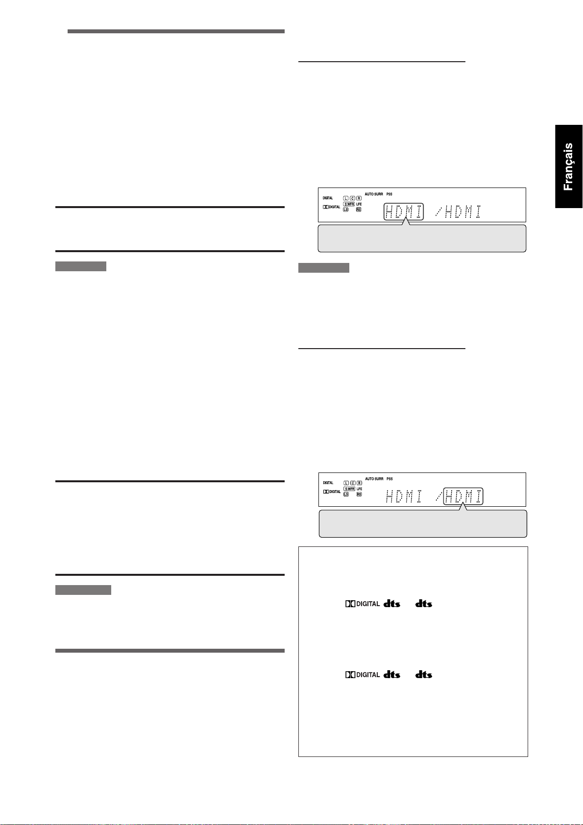
3 Ajustement du volume
Pour augmenter le volume, tournez le
réglage MASTER VOLUME dans le sens des
aiguilles d’une montre (ou appuyez sur
VOLUME + sur la télécommande).
Pour diminuer le volume, tournez le réglage
MASTER VOLUME dans le sens contraire
des aiguilles d’une montre (ou appuyez sur
VOLUME – sur la télécommande).
• Lors de l’ajustement du volume, l’indication du niveau de
volume apparaît sur l’affichage un instant.
ATTENTION:
Réglez toujours le volume au minimum avant de démarrer
une source. Si le volume est réglé sur un niveau élevé, la
soudaine déflagration d’énergie sonore peut endommager de
façon permanente votre ouïe et/ou détruire vos enceintes.
7 Sélection du réglage de l’entrée vidéo
À partir de la télécommande SEULEMENT:
1 Appuyez sur une des touches de
sélection de source pour choisir la source
souhaitée.
2 Appuyez sur VIDEO INPUT pour choisir le
réglage de l’entrée vidéo.
• Chaque fois que vous appuyez sur la touche, le réglage
de l’entrée change comme suit. Ce réglage est mémorisé
pour chaque source.
HDMI = CMPNT (Composantes) = S (S-Vidéo) =
C (Composite) = (retour au début)
REMARQUE
Le niveau de volume peut être ajusté dans une plage de “0”
(minimum) à “50” (maximum).
7 Écoute avec un casque d’écoute
Vous pouvez profiter non seulement des supports stéréo
mais aussi des supports multicanaux à travers votre casque
d’écoute. (Les sons sont sous-mixés sur les canaux avant lors
de la lecture de supports multicanaux).
Connectez un casque d’écoute à la prise
PHONES sur le panneau avant pour mettre
en service le mode HEADPHONE.
L’indicateur HEADPHONE s’allume sur l’affichage.
• Vous pouvez aussi profiter du mode Surround/DSP à travers
le casque d’écoute—mode 3D HEADPHONE (voir page 42).
• Déconnecter le casque d’écoute de la prise PHONES annule
le mode HEADPHONE (ou 3D HEADPHONE) et met en
service les enceintes.
ATTENTION:
• S’assurer de réduire le volume:
– Avant de connecter ou de se mettre le casque sur les
oreilles, car un volume élevé peut endommager le casque
et l’ouïe.
– Avant de remettre en service les enceintes, car un volume
élevé peut être sorti par les enceintes.
• Ne branchez pas de casque d’écoute dans la prise PRECISE
SURROUND SETUP MIC; sinon, une tonalité puissante peut
sortir du casque d’écoute.
REMARQUES
• Lors de l’utilisation du casque d’écoute, les réglages des enceintes
sont sans effet temporairement.
• Les microphones de type écouteur fournis ne peuvent pas être
utilisés comme écouteurs.
Sélection des réglages de l’entrée
vidéo et audio
Vous devez choisir le réglage correct de l’entrée vidéo et audio
pour chaque source en fonction des méthodes de connexion
des pages 9 à 14.
• Dans le cas d’une connexion audio numérique à l’aide des
prises DIGITAL IN à l’arrière de l’ampli-tuner, vous devez
aussi choisir la prise d’entrée numérique correcte (voir page
34).
• Une fois que vous avez réalisé un ajustement, il est
mémorisé pour chaque source.
REMARQUE
Pour “VCR” et “DBS”, réglez HDMI et COMPONENT correctement si
nécessaire (voir page 34).
7 Sélection du réglage de l’entrée audio
À partir de la télécommande SEULEMENT:
1 Appuyez sur une des touches de
sélection de source pour choisir la source
souhaitée.
2 Appuyez sur AUDIO INPUT pour choisir le
réglage de l’entrée audio.
• Chaque fois que vous appuyez sur la touche, le réglage
de l’entrée audio change comme suit. Ce réglage est
mémorisé pour chaque source.
HDMI = DIGITAL = ANALOG = A MULTI =
(retour au début)
HDMI (pour “DVR/DVD”, “VCR” et “DBS”):
Choisissez la source pour la connexion HDMI.
L’ampli-tuner détecte automatiquement le
format du signal d’entrée, puis l’indicateur
du format de signal numérique (LINEAR PCM,
, , ou 96/24) s’allume pour le
signal détecté, et le témoin HDMI sur le panneau
avant s’allume.
DIGITAL*: Choisissez le réglage de l’entrée numérique.
L’ampli-tuner détecte automatiquement le
format du signal d’entrée, puis l’indicateur
de format du signal numérique (LINEAR PCM,
, , ou 96/24) détecté s’allume.
ANALOG*: Choisissez le réglage de l’entrée analogique.
L’indicateur ANALOG s’allume sur l’affichage.
A MULTI (Uniquement pour “DVR/DVD”):
Choisissez ce réglage quand vous connectez un
enregistreur de DVD ou un lecteur de DVD aux
prises DVD MULTI IN (voir page 11). L’indicateur
ANALOG s’allume sur l’affichage.
* Quand “TV” est choisi comme source, seuls “DIGITAL” et
“ANALOG” sont disponibles.
Suite à la page suivante
21
Page 78

REMARQUES
• “HDMI” peut être choisi uniquement quand le réglage de l’entrée
vidéo est aussi “HDMI” (voir page 21).
Le réglage de l’entrée audio peut changer automatiquement si vous
changez le réglage de l’entrée vidéo sur “HDMI” ou un autre réglage
à partir de “HDMI”. Dans ce cas, assurez-vous que le réglage correct
est choisi.
• “DIGITAL” est disponible pour la source affectée à “DIGITAL IN 1”,
“DIGITAL IN 2” ou “DIGITAL IN 3”. Référez-vous à la page 34 pour les
détails.
Réglage initial de l’entrée vidéo et audio pour chaque
source
Source
Réglage
DVR/DVD HDMI HDMI
VCR HDMI HDMI
DBS S DIGITAL
TV — ANALOG
SIRIUS — ANALOG (fixé)
USB — DIGITAL (fixé)
XM — DIGITAL (fixé)
FM — ANALOG (fixé)
AM — ANALOG (fixé)
Entrée vidéo Entrée audio
Les indicateurs suivants de format de signal numérique sur
l’affichage indiquent quel type de signal entre dans l’amplituner. Référez-vous aux pages 39 à 41 pour les détails sur
chaque format de signal numérique.
LINEAR PCM: • S’allume lors de l’entrée des signaux PCM
:
:
96/24:
REMARQUE
Quand “DIGITAL AUTO” ne peut pas reconnaître les signaux
d’entrée, aucun indicateur de format de signal numérique ne
s’allume sur l’affichage.
linéaires.
• Quand un signal PCM multicanaux entre,
“MULTI CH PCM” apparaît un moment sur
l’affichage.
S’allume lors de l’entrée des signaux Dolby
Digital.
• Clignote quand “DOLBY DIGITAL” est
choisi pour un logiciel non codé avec
Dolby Digital.
S’allume quand un signal DTS
conventionnel entre.
• Clignote quand “DTS” est choisi pour
n’importe quel support autre que DTS.
S’allume quand un signal DTS 96/24 entre.
Sélection du mode de décodage
numérique
Quand “HDMI” ou “DIGITAL” est choisi pour le réglage
d’entrée audio (voir page 21), cet ampli-tuner détecte
automatiquement le format du signal numérique entrant et
règle le mode de décodage numérique sur “DIGITAL AUTO”.
• L’indicateur DIGITAL AUTO s’allume sur l’affichage.
Si les symptômes suivants se produisent pendant la lecture
d’un logiciel Dolby Digital ou DTS alors que “DIGITAL AUTO”
est choisi, suivez la procédure ci-dessous:
• Aucun ne sort au début de la lecture.
• Il y a du bruit lors de la recherche ou du saut de chapitres ou
de plages.
À partir de la télécommande SEULEMENT:
Appuyez sur DECODE pour choisir “DOLBY
DIGITAL” ou “DTS”.
• Chaque fois que vous appuyez sur DECODE, le mode de
décodage numérique change comme suit:
DIGITAL AUTO = DOLBY DIGITAL = DTS =
(retour au début)
• Pour reproduire un logiciel codé avec Dolby Digital,
choisissez “DOLBY DIGITAL”.
• Pour reproduire un logiciel codé avec DTS, choisissez “DTS”.
REMARQUES
• Le mode de décodage numérique est fixé sur “DIGITAL AUTO”
quand “USB” ou “XM” est choisi comme source.
• “DOLBY DIGITAL” ou “DTS” est réinitialisé automatiquement à
“DIGITAL AUTO” dans les cas suivants:
– Quand vous mettez l’ampli-tuner hors tension.
– Quand vous choisissez une autre source.
– Quand vous changez le réglage de l’entrée audio (voir page 21).
22
Coupure temporaire du son
À partir de la télécommande SEULEMENT:
Appuyez sur MUTING pour couper le son de
toutes les enceintes et du casque d’écoute
connectés.
“MUTING” apparaît sur l’affichage et le volume est coupé.
Pour rétablir le son, appuyez de nouveau sur MUTING.
• Appuyer sur VOLUME +/– (ou réglage MASTER VOLUME sur
la panneau avant) rétablit aussi le son.
REMARQUE
Lors de la réalisation du réglage Precise Surround Setup ou
quand l’appareil est mis hors tension, la sourdine est annulée
automatiquement.
Modification de la luminosité de
l’affichage
Vous pouvez assombrir l’affichage—Gradateur.
À partir de la télécommande SEULEMENT:
Appuyez répétitivement sur DIMMER.
• Chaque fois que vous appuyez sur la touche, la luminosité
de l’affichage change comme suit:
DIMMER1 Assombrit l’affichage.
DIMMER2 Assombrit l’affichage plus qu’avec le réglage
DIMMER 1.
DIMMER3 Met l’affichage hors service.
(La fonction de gradateur est annulée
temporairement quand vous utilisez l’amplituner.)
DIMMER OFF Annulé le gradateur (affichage normal).
REMARQUE
Lors de la réalisation du réglage Precise Surround Setup, le gradateur
est annulé automatiquement.
Page 79

Mise hors tension de l’appareil avec
la minuterie d’arrêt
Vous pouvez vous endormir en écoutant de la musique—
Minuterie d’arrêt.
À partir de la télécommande SEULEMENT:
Appuyez répétitivement sur SLEEP.
• Chaque fois que vous appuyez sur la touche, l’heure de
mise hors tension change par intervalle de 10 minutes.
L’indicateur SLEEP s’allume sur l’affichage.
Indicateur SLEEP
10min = 20min = 30min = 40min =50min = 60min
= 70min = 80min =90min = OFF (Annulée) =
(retour au début)
Quand l’heure de mise hors tension arrive:
L’appareil se met hors tension automatiquement.
Pour vérifier la durée restante avant la mise hors tension:
Appuyez une fois sur SLEEP.
La durée restante (en minutes) avant la mise hors tension
apparaît.
• Pour changer la durée avant la mise hors tension,
appuyez répétitivement sur SLEEP.
Pour annuler la minuterie d’arrêt:
Appuyez répétitivement sur SLEEP jusqu’à ce que “SLEEP OFF”
apparaisse sur l’affichage. (L’indicateur SLEEP s’éteint).
• La minuterie d’arrêt est aussi annulée si vous mettez l’amplituner hors tension.
Pour rendre les sons naturels
Le convertisseur CC (Compression compensative) de JVC
élimine le scintillement et les fluctuations afin d’obtenir
une réduction importante de la distorsion numérique
par un traitement des données musicales numérique en
quantification 24 bits et par l’extension de la fréquence
d’échantillonnage à 176,4 kHz (pour les signaux fs 44,1
kHz)/192 kHz (pour les signaux fs 48 kHz), sur les enceintes
avant.
En utilisant le convertisseur CC, vous pouvez obtenir un
champ sonore naturel pour les sources numériques ainsi que
pour les sources analogiques.
• Une fois que vous avez réalisé un ajustement, il est
mémorisé pour chaque source.
Appuyez répétitivement sur
CC CONVERTER.
• Chaque fois que vous appuyez sur la touche, le mode
change comme suit:
CC CNVRTR 1 Choisissez ce réglage lors de la lecture
d’une source analogique ou une source
numérique avec un signal sonore non
compressé (Linear PCM).
L’indicateur CC CONVERTER 1 s’allume sur
l’affichage.
CC CNVRTR 2 Choisissez ce réglage lors de la lecture
d’une source avec un signal sonore
compressé (Dolby Digital ou DTS).
L’indicateur CC CONVERTER 2 s’allume sur
l’affichage.
CC CNVRTR OFF Choisissez ce réglage quand vous n’utilisez
pas le convertisseur CC.
Ajustement de base et mémorisation
automatique
Cet appareil mémorise les réglages sonores pour chaque
source:
• Quand vous mettez l’appareil hors tension
• Quand vous changez la source.
Quand vous changez la source, les réglages mémorisés pour
la nouvelle source choisie sont rappelés automatiquement.
Les réglages suivants peuvent être mémorisés pour chaque
source:
• Réglage de l’entrée vidéo (voir page 21)
• Réglage de l’entrée audio (voir page 21)
• Convertisseur CC (voir la colonne de gauche)
• Mode de minuit (voir page 33)
• Courbes d’égalisation numérique (voir page 36)
• Accentuation de graves (voir page 37)
• Mode d’atténuation de l’entrée (voir page 37)
• Sélection du mode Surround/DSP (voir page 44)
REMARQUE
Si la source est “FM” ou “AM”, vous pouvez mémoriser un réglage
différent pour chaque bande.
Indicateurs de signal et d’enceinte sur
l’affichage
Indicateurs de signal Indicateurs d’enceinte
Les indicateurs de signal suivant s’allument:
L: • Quand l’entrée numérique est choisie: S’allume
R: • Quand l’entrée numérique est choisie: S’allume
C: S’allume lors de l’entrée du signal du canal central.
LS: S’allume lors de l’entrée du signal du canal surround
RS: S’allume lors de l’entrée du signal du canal surround
S: S’allume lors de l’entrée d’un signal monophonique
SB: S’allume lors de l’entrée d’un signal de canal
LFE: S’allume lors de l’entrée du signal de canal LFE.
• Quand “A MULTI” est choisi pour le réglage de l’entrée audio
• Lors de la lecture d’un son numérique multicanaux enregistré
Les indicateurs d’enceinte s’allument de la façon
suivante:
• L’indicateur de caisson de grave (
• Les autres indicateurs d’enceinte s’allument uniquement
lors de l’entrée du signal du canal gauche.
• Quand l’entrée analogique est choisie: Toujours
allumé.
lors de l’entrée du signal du canal droit.
• Quand l’entrée analogique est choisie: Toujours
allumé.
gauche.
droit.
Surround.
surround arrière.
REMARQUES
(voir page 21), tous les indicateurs de signaux sauf “SB” et “S”
s’allument.
en DVD-Audio avec une connexion HDMI (voir pages 9 et 21), les
indicateurs de signaux peuvent ne pas s’allumer correctement.
) s’allume quand
“SUBWOOFER” est réglé sur “YES”. Pour les détails, référezvous à la page 30.
quand l’enceinte correspondante est réglée sur
“SML (petit)” ou “LRG (grand)” et aussi quand elles sont
nécessaires pour la lecture actuelle.
23
Page 80
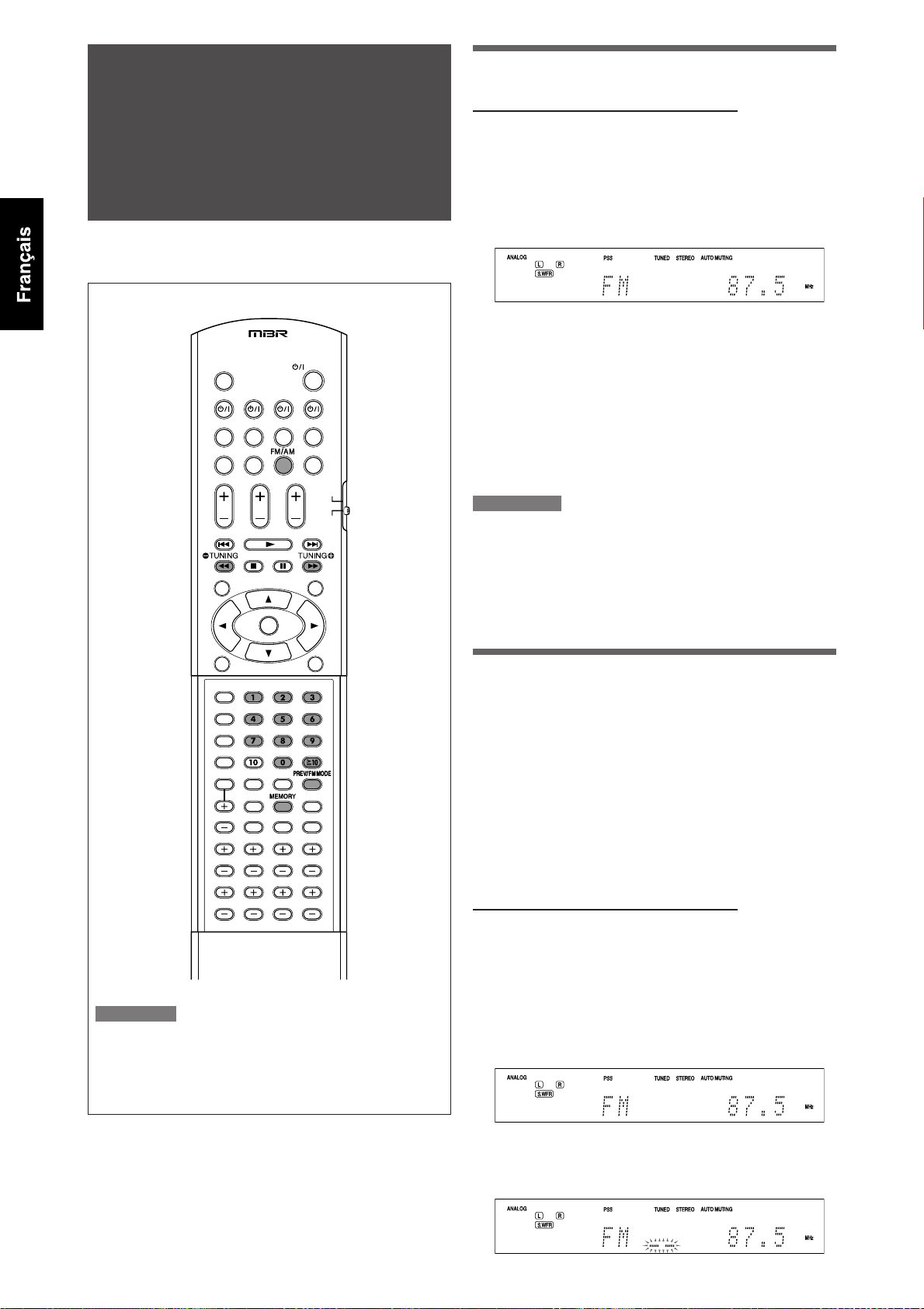
Fonctionnement du
tuner FM/AM
La commande du tuner FM/AM est réalisée principalement
à partir de la télécommande.
Accord manuel des stations
À partir de la télécommande SEULEMENT:
1 Appuyez sur FM/AM pour choisir la
bande.
La dernière station reçue de la bande choisie est accordée
et les touches.
• Chaque fois que vous appuyez sur la touche, la bande
alterne entre “FM” et “AM”.
2 Appuyez répétitivement sur TUNING 9
ou ( TUNING ou maintenez les touches
pressées jusqu’à ce que la station
souhaitée soit accordée.
• Appuyer sur (ou maintenir pressée) TUNING 9
augmente la fréquence.
• Appuyer sur (ou maintenir pressée) ( TUNING diminue
la fréquence.
REMARQUES
• Si vous maintenez pressée puis relâchée TUNING 9 ou ( TUNING,
la fréquence continue de changer jusqu’à ce qu’une station soit
accordée.
• Quand une station de signal suffisamment fort est accordée,
l’indicateur TUNED s’allume sur l’affichage.
• Quand un programme FM stéréo est reçu, l’indicateur STEREO
s’allume aussi.
REMARQUE
Si vous avez choisi “FM” ou “AM” en utilisant le sélecteur SOURCE
SELECTOR sur le panneau avant, il se peut que la télécommande
ne fonctionne pas pour commander le tuner. Pour commander le
tuner avec la télécommande, choisissez “FM” ou “AM” en utilisant
le touche FM/AM sur la télécommande.
Utilisation de l’accord par préréglage
Une fois qu’un numéro de canal a été affecté à une station,
la station peut être accordée rapidement en choisissant
simplement son numéro. Vous pouvez prérégler un maximum
de 30 stations FM et 15 stations AM.
7 Pour mémoriser les stations préréglées
Avant de commencer, rappelez-vous...
Les étapes suivantes doivent être exécutées dans un délai
donné. Si le réglage est annulé avant la fin, recommencez à
partir de l’étape
À partir de la télécommande SEULEMENT:
1 Accordez la station que vous souhaitez
prérégler (voir “Accord manuel des
stations” ci-dessus).
• Si vous souhaitez mémoriser le mode de réception FM
pour cette station, choisissez le mode de réception
FM souhaité. Référez-vous à “Sélection du mode de
réception FM” à la page 25.
2.
24
2 Appuyez sur MEMORY.
La position du numéro de canal clignote sur l’affichage
pendant environ 5 secondes.
Page 81

3 Appuyez sur les touches numériques
(0 – 9, h10) pour choisir un numéro de
canal quand la position de numéro de
canal clignote.
• Pour le numéro de canal 5, appuyez sur 5.
• Pour le numéro de canal 10, appuyez sur h10, 1 puis sur
0.
• Pour le numéro de canal 25, appuyez sur h10, 2 puis sur
5.
4 Appuyez de nouveau sur MEMORY
pendant que le numéro du canal choisi
clignote sur l’affichage.
Le numéro de canal choisi s’arrête de clignoter.
Le numéro de canal est affecté à la station.
5 Répétez les étapess 1 à 4 jusqu’à ce que
toutes les stations souhaitées soient
mémorisées.
Pour effacer une station prérégler en mémoire:
Mémoriser une nouvelle station sur un numéro de canal déjà
utilisé efface la station précédemment mémorisée.
Sur le panneau avant:
2 1, 3
Avant de commencer, rappelez-vous...
Les étapes suivantes doivent être exécutées dans un délai
donné. Si le réglage est annulé avant la fin, recommencez à
partir de l’étape
2.
1 Tournez le sélecteur SOURCE SELECTOR
pour choisir “FM” ou “AM”.
La dernière station reçue de la bande choisie est accordée
et les touches.
2 Appuyez sur TUNER PRESET.
“P” apparaît sur l’affichage et MULTI JOG peut être utilisé
pour choisir les canaux préréglés.
3 Tournez la molette MULTI JOG pour
choisir un numéro de canal.
• Pour augmenter le numéro du canal préréglé, tournez
la molette MULTI JOG dans le sens des aiguilles d’une
montre.
• Pour diminuer le numéro du canal préréglé, tournez la
molette MULTI JOG dans le sens contraire des aiguilles
d’une montre.
7 Pour accorder une station préréglée
A partir de la télécommande:
1 Appuyez sur FM/AM pour choisir la
bande.
La dernière station reçue de la dernière bande choisie est
accordée et les touches numériques peuvent être utilisées
pour la sélection des canaux préréglés.
• Chaque fois que vous appuyez sur FM/AM, la bande
alterne entre “FM” et “AM”.
2 Appuyez sur les touches numériques
(0 – 9, h10) pour choisir un numéro de
canal préréglé.
• Pour le numéro de canal 5, appuyez sur 5.
• Pour le numéro de canal 10, appuyez sur h10, 1 puis sur
0.
• Pour le numéro de canal 25, appuyez sur h10, 2 puis sur
5.
Sélection du mode de réception FM
Quand une émission FM est difficile à recevoir ou parasitée,
vous pouvez changer le mode de réception FM.
• Vous pouvez mémoriser le mode de réception FM pour
chaque station préréglée (voir page 24).
À partir de la télécommande SEULEMENT:
Lors de l’écoute d’une station FM, appuyez
sur FM MODE.
• Chaque fois que vous appuyez sur la touche, le mode de
réception FM alterne entre “AUTO MUTING” et “MONO”.
AUTO MUTING Normalement choisissez ce réglage.
Quand un programme est diffusé en stéréo,
vous entendrez le son en stéréo; et quand
il est diffusé en monaural, vous l’entendrez
en monaural. Ce mode est aussi pratique
pour supprimer le bruit des parasites entre
les stations. L’indicateur AUTO MUTING
s’allume sur l’affichage.
MONO Choisissez ce réglage pour améliorer la
réception (mais l’effet stéréo est perdu).
Dans ce mode, du bruit est entendu lors
de l’accord entre les stations. L’indicateur
AUTO MUTING s’éteint de l’affichage.
(L’indicateur STEREO s’éteint aussi).
Réglage initial: AUTO MUTING
25
Page 82

Fonctionnement de
la radio satellite XM
Cet ampli-tuner est XM Ready®.
• Avant de commencer, référez-vous aussi aux manuels du
minisyntoniseur XM et de la station d’accueil pour la maison
du minisyntoniseur XM (non fournis).
Préparations
Pour écouter la radio satellite XM, vous avez besoin de ce qui suit:
– Le système de minisyntoniseur XM*1 (non fourni)—
minisyntoniseur XM et station d’accueil pour la maison du
minisyntoniseur XM
– Un abonnement à la radio satellite XM*
*1 Pour connecter le système de minisyntoniseur XM à cet
ampli-tuner, référez-vous à la page 7.
2
*
Les canaux suivants sont disponibles sans souscription:
– Canal 0: Ce canal sert à vérifier le code d’identification
– Canal 1: C’est le canal “XM Preview”.
Comment souscrire
Abonnement mensuel au service XM vendu séparément.
Le minisyntoniseur XM et station d’accueil pour la maison
(comprenant une antenne) requis pour recevoir le service XM
(vendu séparément). Des frais divers et des taxes peuvent
s’appliquer, y compris des frais d’activation initiale. Les frais
d’abonnement mentionnés s’appliquent aux consommateurs
seulement. Le service XM est disponible dans 48 états
adjacents des États-Unis et au Canada. Vous pouvez activer
votre service XM Satellite Radio en ligne au <www.xmradio.
ca> ou en téléphonant au 1 877 GET-XMSR (1 877 438-9766).
Pour l’abonnement, vous avez besoin du numéro
d’identification de votre radio satellite XM. Pour vérifier le
numéro d’identification, suivez la procédure ci-dessous.
Comment vérifier le code d’identification de la radio
satellite XM
Après la connexion:
de la radio satellite XM.
1 Appuyez sur XM sur la télécommande ou
tournez le sélecteur SOURCE SELECTOR
sur le panneau avant pour choisir “XM”
comme source.
2
REMARQUE
Si vous avez choisi “XM” en utilisant le sélecteur SOURCE SELECTOR
sur le panneau avant, il se peut que la télécommande ne
fonctionne pas pour commander la radio satellite XM. Pour utiliser
la télécommande pour commander la radio satellite XM, choisissez
“XM” en utilisant la touche XM de la télécommande.
7 À propos de la radio satellite XM
XM Satellite Radio offre une diversité extraordinaire
d’émissions de musique en direct sans annonces
publicitaires, le meilleur en matière de sports, de nouvelles,
d’émissions-débats et de divertissement. XM diffuse un
signal audionumérique de qualité supérieure à travers le
pays. Du rock au reggae, de la musique classique au hip-hop,
XM a quelque chose pour tous les amateurs de musique.
L’engagement de XM à offrir une riche sélection de musique
n’est égalée que par sa passion pour les événements sportifs
en direct, les émissions-débats, les nouvelles sur le vif, les
monologues comiques, les émissions pour les enfants et plus
encore.
De l’information concernant XM Canada se trouve en ligne à
<www.xmradio.ca>.
XM Ready® est une marque déposée de XM Satellite Radio
Inc. Tous droits réservés.
Pour les opérations SIRIUS Satellite Radio, référez-vous
à la page 47.
26
2 Accordez “Canal 0” (voir “Pour accorder
les canaux” à la page 27) pour vérifier
le code d’identification de votre radio
satellite XM.
“RADIO ID” et le code d’identification à 8 caractères
(alphanumérique) apparaissent alternativement sur l’affichage.
Pour annuler l’affichage du code d’identification
Choisissez n’importe quel autre canal que “Canal 0”.
Écoute de la radio satellite XM
1 Appuyez sur XM sur la télécommande ou
tournez le sélecteur SOURCE SELECTOR
sur le panneau avant pour choisir “XM”
comme source.
Le dernier canal reçu est accordé.
“XM” apparaît puis le nom du canal apparaît sur l’affichage.
Nombre de canaux Nom du canal
2 Accordez le canal souhaité.
Vous pouvez accorder les canaux avec une des méthodes
suivantes:
– Recherche de canal
– Recherche de catégorie
– Accès direct aux canaux
Pour les détails, référez-vous à “Pour accorder les canaux”
à la page 27.
Page 83

7 Pour accorder les canaux
À partir de la télécommande SEULEMENT:
Recherche de canal
Vous pouvez recherche et accorder tous les canaux.
1 Appuyez sur XM pour choisir “XM”
comme source.
2 Appuyez répétitivement sur CHANNEL
+/– ou maintenez la touche pressée
jusqu’à ce que le numéro du canal
souhaité apparaisse sur l’affichage.
• Appuyer sur (ou maintenir pressée) CHANNEL +
augmente le numéro de canal.
• Appuyer sur (ou maintenir pressée) CHANNEL – diminue
le numéro de canal.
REMARQUE
Pendant la recherche, les canaux invalides et ceux auxquels vous
n’avez pas souscrits sont sautés.
Recherche de catégorie
Vous pouvez choisir la catégorie des canaux et accorder
uniquement les canaux de la catégorie choisie.
Avant de commencer, rappelez-vous...
Les étapes suivantes doivent être exécutées dans un délai
donné. Si le réglage est annulé avant la fin, recommencez à
partir de l’étape
2.
1 Appuyez sur XM pour choisir “XM”
comme source.
2 Appuyez sur CAT 9 ou ( CAT.
L’ampli-tuner entre en mode de recherche de catégorie.
Le nom de la catégorie du canal actuellement choisi et “>”
clignotent sur l’affichage pendant environ 15 secondes.
Nombre de canaux Nom de la catégorie
Accès direct aux canaux
Vous pouvez accorder le canal souhaité directement en
entrant le numéro de canal.
Avant de commencer, rappelez-vous...
Les étapes suivantes doivent être exécutées dans un délai
donné. Si le réglage est annulé avant la fin, recommencez à
partir de l’étape
2.
1 Appuyez sur XM pour choisir “XM”
comme source.
2 Appuyez sur la touche DIRECT.
L’ampli-tuner entre en mode d’accès direct et les touches
numériques peuvent être utilisées pour entrer les numéros
de canal.
La position du numéro de canal clignote sur l’affichage
pendant environ 5 secondes.
3 Appuyez sur les touches numériques
(0 – 9, h10) pour entrer le numéro de
canal souhaité quand la position de
numéro de canal clignote.
• Pour le numéro de canal 005, appuyez sur 5.
• Pour le numéro de canal 010, appuyez sur h10, 1 puis
sur 0.
• Pour le numéro de canal 025, appuyez sur h10, 2 puis
sur 5.
• Pour le numéro de canal 115, appuyez sur h10, h10, 1,
1, puis sur 5.
Utilisation de l’accord par préréglage
Une fois qu’un numéro de préréglage a été affecté à un
canal, le canal peut être accordé rapidement en choisissant
simplement son numéro. Vous pouvez prérégler un maximum
de 30 canaux.
7 Pour mémoriser les canaux préréglés
3 Appuyez répétitivement sur CAT 9
ou ( CAT pour affichage le nom de
la catégorie souhaitée sur l’affichage
pendant que “>” clignote.
4 Appuyez répétitivement sur CHANNEL
+/– ou maintenez la touche pressée
jusqu’à ce que le canal souhaité soit
accordé.
• Appuyer sur (ou maintenir pressée) CHANNEL +
augmente le numéro de canal compris la catégorie
choisie.
• Appuyer sur (ou maintenir pressée) CHANNEL – diminue
le numéro de canal compris la catégorie choisie.
REMARQUE
Pendant la recherche, les canaux invalides et ceux auxquels vous
n’avez pas souscrits sont sautés.
Avant de commencer, rappelez-vous...
Les étapes suivantes doivent être exécutées dans un délai
donné. Si le réglage est annulé avant la fin, recommencez à
partir de l’étape
2.
À partir de la télécommande SEULEMENT:
1 Accordez le canal que vous souhaitez
prérégler (voir “Pour accorder les
canaux” sur la colonne de gauche).
2 Appuyez sur MEMORY.
La position du numéro de préréglage clignote sur
l’affichage pendant environ 5 secondes.
3 Appuyez sur les touches numériques
(0 – 9, h10) pour choisir un numéro de
préréglage quand la position de numéro
préréglé clignote.
• Pour le numéro de préréglage 5, appuyez sur 5.
• Pour le numéro de préréglage 10, appuyez sur h10, 1
puis sur 0.
• Pour le numéro de préréglage 25, appuyez sur h10, 2
puis sur 5.
Suite à la page suivante
27
Page 84

4 Appuyez de nouveau sur MEMORY
pendant que le numéro de préréglage
choisi clignote sur l’affichage.
5 Répétez les étapes 1 à 4 jusqu’à ce
que tous les canaux souhaités soient
mémorisés.
Changement des informations des
canaux
Lors de l’écoute de la radio satellite XM, l’information du canal
choisi actuellement apparaît sur l’affichage.
Vous pouvez changer le type d’information du canal.
Pour effacer un canal préréglé en mémoire
Mémoriser un nouveau canal sur un numéro déjà utilisé efface
le canal précédemment mémorisé.
7 Pour accorder un canal préréglé
A partir de la télécommande:
1 Appuyez sur XM.
Le dernier canal reçu est accordé.
2 Appuyez sur les touches numériques
(0 – 9, h10) pour choisir un numéro de
canal préréglé.
• Pour le numéro de préréglage 5, appuyez sur 5.
• Pour le numéro de préréglage 10, appuyez sur h10, 1
puis sur 0.
• Pour le numéro de préréglage 25, appuyez sur h10, 2
puis sur 5.
Sur le panneau avant:
Avant de commencer, rappelez-vous...
Les étapes suivantes doivent être exécutées dans un délai
donné. Si le réglage est annulé avant la fin, recommencez à
partir de l’étape
2.
1 Tournez le sélecteur SOURCE SELECTOR
pour choisir “XM”.
Le dernier canal reçu est accordé.
À partir de la télécommande SEULEMENT:
Appuyez sur DISPLAY.
Chaque fois que vous appuyez sur la touche, l’information du
canal change comme suit:
CHAN (nom du canal)* = NAME (nom de l’artiste/vedette)
= TITLE (titre de chanson/programme) = CAT (nom de la
catégorie) = (Retour au début)
* CHAN (nom du canal) est le réglage initial.
EX.: Quand le nom de la catégorie est choisi:
Après 1 seconde
REMARQUES
• Si vous mettez l’appareil hors tension ou choisissez une autre
source, l’affichage retourne au réglage initial.
• Quand vous accordez un autre canal, le nom de canal apparaît puis
l’information du canal que vous avez choisie apparaît.
• Quand le texte d’information ne peut pas être affiché en une fois, le
texte défile.
• Certains caractères ne peuvent pas être affichées directement.
2 Appuyez sur TUNER PRESET.
“P” clignote sur l’affichage et MULTI JOG peut être utilisé
pour choisir les canaux préréglés.
3 Tournez la molette MULTI JOG pour
choisir un numéro de préréglage.
• Pour augmenter le numéro préréglé, tournez la molette
MULTI JOG dans le sens des aiguilles d’une montre.
• Pour diminuer le numéro préréglé, tournez la molette
MULTI JOG dans le sens contraire des aiguilles d’une
montre.
7 Messages sur l’affichage
Quand un problème se produit, un message apparaît sur l’affichage. Dans ce cas, référez-vous à la solution suivante.
Message Cause Possible Solution
NO SIGNAL Les signaux sont trop faibles.
CHECK ANTENNA L’antenne de la station d’accueil pour la
maison du minisyntoniseur XM n’est pas
connectée correctement.
LOADING Cet ampli-tuner est en train de charger les
OFF AIR Le canal choisi n’émet actuellement aucun
UPDATING Le dernier code de cryptage a été mis à jour. Attendez que la mise à jour soit terminée.
• Nombre de canaux et “-----”
• Numéro de préréglage,
numéro de canal et “-----”
• Nombre de canaux et “CH---”
• Numéro de préréglage et
“---<CH---”
données d’informations du canal et audio.
signal.
Il n’y a pas de texte d’information pour le
canal choisi. —
Le canal choisi n’existe pas ou vous n’avez
pas pris de souscription pour ce canal. —
Déplacez l’antenne
minisyntoniseur XM
vers le sud où dans un endroit ou le canal 1
(“Channel 1”) peut être entendu correctement.
Vérifiez les connexions (voir page 7).
Cela prend plusieurs minutes. Attendez que le
chargement soit terminé.
Choisissez un autre canal.
pour la maison du
près d’une fenêtre dirigée
28
Page 85

Réglages de base
Pour obtenir le meilleur effet sonore possible des modes
Surround/DSP (voir pages 39 à 44), vous devez régler
l’information des enceintes et du caisson de grave une fois
que toutes les connexions ont été terminées. Nous expliquons
dans les pages 29 à 34, comment effectuer les réglages des
enceintes et les autres réglages de base de l’ampli-tuner.
Éléments des réglages de base
Vous pouvez ajuster les éléments suivants. Référez-vous aux
pages entre parenthèses pour plus de détails.
• Vous ne pouvez pas choisir les éléments qui ne sont pas
disponibles pour le réglage actuel. Par exemple, quand
“S BACK SPK” est réglé sur “NO”, vous ne pouvez pas choisir
les réglages suivants:
S BACK OUT, S BACK DIST, S BACK L DIST, S BACK R DIST
Éléments Pour
EX/ES/PLIIx Choisissez le mode de reproduction
EX/ES/PLIIx. (32)
DUAL MONO Choisir le canal sonore Dual Mono. (32)
SUBWOOFER OUT Choisir le son émis par le caisson de
grave. (33)
CROSSOVER* Choisir la fréquence de coupure du
caisson de grave. (33)
LFE ATT Atténuer les sons graves (LFE). (33)
MIDNIGHT MODE Reproduit un son puissant la nuit. (33)
DIGITAL IN 1 Choisir l’appareil connecté à la prise
coaxiale numérique—1(DVR/DVD). (34)
DIGITAL IN 2 Choisit l’appareil connecté à la prise
numérique optique—2(DBS). (34)
DIGITAL IN 3 Choisit l’appareil connecté à la prise
numérique optique—3(VCR). (34)
AUDIO DELAY Réglez le temps de retard audio pour
corriger la synchronisation entre les
signaux vidéo et audio. (34)
HDMI SELECT Choisissez la source pour la prise HDMI
VCR (DBS) IN. (34)
CMPNT SELECT Choisissez la source pour les prises
COMPONENT VCR (DBS) IN. (34)
VIDEO OUTPUT Choisissez le signal vidéo de sortie. (34)
* Si vous avez réalisé le réglage Precise Surround Setup aux
pages 16 et 18, ces réglages ne sont pas nécessaires.
Éléments Pour
SUBWOOFER* Enregistrer le caisson de grave. (30)
FRONT SPK* Enregistrer la taille des enceintes avant.
(30)
CENTER SPK* Enregistrer la taille de l’enceinte
centrale. (30)
SURROUND SPK* Eregister la taille des enceintes
surround. (30)
S BACK SPK* Enregistrer la taille des enceintes
surround arrière. (30)
S BACK OUT* Enregistrez votre nombre d’enceintes
surround arrière. (31)
DIST UNIT Choisir l’unité de mesure pour la
distance des enceintes. (31)
FRONT L DIST* Enregistre la distance de l’enceinte
avant gauche à votre position d’écoute.
(31)
FRONT R DIST* Enregistre la distance de l’enceinte
avant droite à votre position d’écoute.
(31)
CENTER DIST* Enregistre la distance de l’enceinte
centrale à votre position d’écoute. (31)
SURR L DIST* Enregistre la distance de l’enceinte
surround gauche à votre position
d’écoute. (31)
SURR R DIST* Enregistre la distance de l’enceinte
surround droite à votre position
d’écoute. (31)
S BACK DIST* Enregistrez la distance de l’enceinte
surround arrière à votre position
d’écoute lors de l’utilisation d’une seule
enceinte pour les enceintes surround
arrière. (31)
S BACK L DIST* Enregistrez la distance de l’enceinte
surround arrière gauche à votre point
d’écoute. (31)
S BACK R DIST* Enregistrez la distance de l’enceinte
surround arrière droite à votre point
d’écoute. (31)
REMARQUE
Certains réglages ci-dessus ne sont pas disponibles dans les cas
suivants:
– Quand “A MULTI” est choisi pour le réglage de l’entrée audio (voir
page 11)
– Quand des signaux multicanaux PCM (voir page 41) sont entrés et
que “HDMI” est choisi pour le réglage d’entrée audio (voir page 11)
29
Page 86

Procédure de fonctionnement
1, 7 3, 5 2, 4
Sur le panneau avant SEULEMENT:
Avant de commencer, rappelez-vous...
Les étapes suivantes doivent être exécutées dans un délai
donné. Si le réglage est annulé avant la fin, recommencez à
partir de l’étape
Ex.: Lors du réglage de la prise DIGITAL IN 1
1 Appuyez sur SETTING.
MULTI JOG peut maintenant être utilisé pour les réglages.
2 Tournez la molette MULTI JOG jusqu’à ce
que l’élément que vous souhaitez régler
apparaisse sur l’affichage.
• Le réglage change comme suit quand vous tournez la
molette MULTI JOG:
1.
Réglage des enceintes
Pour obtenir le meilleur son Surround possible avec les
modes Surround et DSP, il faut enregistrer des informations
sur la disposition des enceintes après que leur connexion est
terminée.
• Si vous avez réalisé le réglage Precise Surround Setup aux
pages 16 et 18, les réglages suivants ne sont pas nécessaires.
7 Réglage de l’information du caisson de grave
—SUBWOOFER
Choisissez si un caisson de grave est connecté ou non.
SUBWFR YES Choisissez ce réglage quand vous avez
connecté un caisson de grave.
L’indicateur de caisson de grave (
s’allume sur l’affichage. Vous pouvez ajuster
le niveau de sortie du caisson de grave (voir
page 36).
SUBWFR NO Choisissez ce réglage quand vous n’avez
pas connecté de caisson de grave. Choisir
ce réglage change le réglage de la taille des
enceintes avant sur “LRG” (voir ci-dessous).
Réglage initial: NO
)
SUBWOOFER Ô FRONT SPK Ô CENTER SPK Ô
SURROUND SPK Ô S BACK SPK Ô S BACK OUT Ô
DIST UNIT Ô FRONT L DIST Ô FRONT R DIST Ô
CENTER DIST Ô SURR L DIST Ô SURR R DIST Ô
S BACK DIST Ô S BACK L DIST Ô S BACK R DIST Ô
EX/ES/PLIIx Ô DUAL MONO Ô SUBWOOFER OUT
Ô CROSSOVER Ô LFE ATT Ô MIDNIGHT MODE Ô
DIGITAL IN 1 Ô DIGITAL IN 2 Ô DIGITAL IN 3 Ô
AUDIO DELAY Ô HDMI SELECT Ô CMPNT SELECT
Ô VIDEO OUTPUT Ô (retour au début)
3 Appuyez sur SET.
Le réglage actuel pour l’élément choisi apparaît.
4 Tournez la molette MULTI JOG pour
choisir le réglage approprié.
DVR/DVD Ô DBS Ô VCR Ô TV
5 Appuyez sur SET.
Votre réglage est mémorisé.
7 Réglage de la taille des enceintes—FRONT
SPK (enceintes avant), CENTER SPK (enceinte
centrale), SURROUND SPK (enceintes
surround), S BACK SPK (enceintes surround
arrière)
Enregistrez la taille des enceintes connectées.
LRG (grand) Choisissez ce réglage quand la taille du cône
du haut-parleur est supérieure à 12 cm.
SML (petit) Choisissez ce réglage quand la taille du cône
du haut-parleur est inférieure à 12 cm.
NO Choisissez ce réglage quand vous n’avez
pas connecté d’enceinte. (Ne peut pas être
choisi pour les enceintes avant.)
Réglage initial: LRG (pour les enceintes avant)
SML (pour les autres enceintes)
REMARQUES
• Si vous avez choisi “SML (petit)” pour la taille des enceintes avant,
vous ne pouvez pas choisir “LRG (grand)” pour les autres enceintes.
• Quand “SUBWOOFER” est réglé sur “NO”, la taille des enceintes
avant est fixée sur “LRG (grand)” (et vous ne pouvez pas choisir
“SML (petit)”).
• Quand “SURROUND SPK” est réglé sur “SML (petit)”, vous ne pouvez
pas choisir “LRG (grand)” pour l’enceinte surround arrière.
• Quand “SURROUND SPK” est réglé sur “NO”, le réglage de l’enceinte
surround arrière est fixé sur “NO”.
6 Répétez les étapes 2 à 5 pour régler si
nécessaire d’autres éléments.
7 Appuyez sur SETTING.
L’indication de la source réapparaît sur l’affichage.
30
Page 87

7 Réglage des enceintes surround arrière—
S BACK OUT
Enregistrez le nombre d’enceintes surround arrière.
SB OUT 1SPK Choisissez ce réglage quand vous utilisez
une seule enceinte surround arrière.
SB OUT 2SPK Choisissez ce réglage quand vous utilisez
deux enceintes surround arrière.
Réglage initial: 2SPK
REMARQUES
• Quand “S BACK SPK” est réglé sur “NO”, vous ne pouvez pas choisir
“S BACK OUT”.
• Quand “S BACK OUT” est réglé sur “1SPK”, connectez l’enceinte
surround arrière à la prise d’enceinte surround arrière gauche (voir
page 8). Aucun son ne sort de l’enceinte surround arrière si vous la
connectez à la prise de l’enceinte surround arrière droite.
7 Réglage de la distance des enceintes
La distance de votre position d’écoute aux enceintes est un
des éléments importants permettant d’obtenir le meilleur
effet sonore possible des modes Surround/DSP.
En se référant à la distance des enceintes, l’ampli-tuner règle
automatiquement le temps de retard du son de chaque
enceinte de façon que le son de chaque enceinte vous
parvienne en même temps.
C
FL FR
3,3 m
2,7 m
(9 pieds)
2,1 m
(7 pieds)
2,4 m
(8 pieds)
SBL SBR
Dans ce cas, réglez la distance comme suit:
Enceinte avant gauche (FL): 3,0 m (10 pieds)
Enceinte avant droite (FR): 3,0 m (10 pieds)
Enceinte centrale (C): 3,0 m (10 pieds)
Enceinte surround gauche (SL): 2,7 m (9 pieds)
Enceinte surround droite (SR): 2,7 m (9 pieds)
Enceinte surround arrière gauche (SBL): 2,4 m (8 pieds)
Enceinte surround arrière droite (SBR): 2,4 m (8 pieds)
(11 pieds)
3,0 m
(10 pieds)
SRSL
• Unité de mesure—DIST UNIT
Choisissez l’unité de mesure vous souhaitez utiliser.
D UNIT meter Choisissez ce réglage pour régler la
distance en mètres.
D UNIT feet Choisissez ce réglage pour régler la
distance en pieds.
Réglage initial: meter
• Distance des enceintes—
FRONT L DIST (pour enceinte avant gauche), FRONT R
DIST (pour enceinte avant droite), CENTER DIST (pour
enceinte centrale), SURR L DIST (pour enceinte surround
gauche), SURR R DIST (pour enceinte surround droite), S
BACK L DIST (pour l’enceinte surround arrière gauche), S
BACK R DIST (pour l’enceinte surround arrière droite)
Plage d’ajustement:
Réglage initial: 3,0 m (10 pieds) pour toutes les
0,3 m à 9,0 m par intervalles de 0,15 m
(1 pied à 30 pieds par intervalles de 0,5
pieds)
enceintes
REMARQUES
• Vous ne pouvez pas réglage la distance des enceintes pour les
quelles vous avez choisi “NO”.
• Si vous avez choisi “1SPK” pour “S BACK OUT” (voir la colonne de
gauche), “S BACK DIST” apparaît à la place de “S BACK L DIST” et “S
BACK R DIST”.
31
Page 88

Mise en service du réglage EX/ES/PLIIx
Sélection du canal principal ou
—EX/ES/PLIIx
En fonction de ce réglage, les modes Surround disponibles
pour les supports numériques multicanaux varient—
reproduction EX/ES/PLIIx (7,1 canaux) ou reproduction 5,1
canaux. Choisissez le réglage approprié à votre goût.
• Pour connaître la relation entre le réglage EX/ES/PLIIx et les
modes Surround disponibles, référez-vous à la page 42.
• Pour mettre en service le mode Surround, référez-vous à la
page 43.
AUTO En fonction du signal entrant, un mode
Surround approprié est appliqué.
• Pour les supports Dolby Digital Surround
EX et DTS-ES, la reproduction 7,1 canaux
est appliquée*.
• Pour les autres supports codé multicanaux
(4 canaux ou plus), la reproduction sur 5,1
canaux est appliquée.
ON Choisissez ce réglage pour appliquer
la reproduction 7,1 canaux à la fois aux
supports 5,1 canaux et aux supports 6,1
canaux.
PLIIx MOVIE Choisissez ce réglage pour appliquer la
reproduction PLIIx MOVIE (7,1 canaux) aux
supports codés en 5,1 canaux et 6,1 canaux.
PLIIx MUSIC Choisissez ce réglage pour appliquer la
reproduction PLIIx MUSIC (7,1 canaux) aux
supports codés en 5,1 canaux et 6,1 canaux.
OFF Choisissez ce réglage pour annuler la
reproduction EX/ES/PLIIx (7,1 canaux).
Réglage initial: AUTO
* Pour certains supports Dolby Digital Surround EX, la
reproduction Dolby Digtal à 5,1 canaux (“DOLBY DIGITAL”)
peut être appliquée même si vous avez choisi “AUTO”. Dans
ce cas, choisissez “ON” pour appliquer “DOLBY D EX”. (Voir
page 42.)
secondaire—DUAL MONO
Vous pouvez choisir le son (canal) de lecture que vous
souhaitez pendant la lecture d’un support numérique
enregistré (ou diffusé) en mode Dual Mono (voir page 41), qui
comprend deux canaux monoraux séparés. Quand l’amplituner détecte des signaux Dual Mono, l’indicateur DUAL
MONO s’allume sur l’affichage.
D MONO MAIN Choisissez ce réglage pour reproduire le
canal principal (Ch 1).*
L’indicateur de signal “L” s’allume quand
ce canal est reproduit.
D MONO SUB Choisissez ce réglage pour reproduire le
canal secondaire (Ch 2).*
L’indicateur de signal “R” s’allume quand
ce canal est reproduit.
D MONO ALL Choisissez ce réglage pour reproduire le
canal principal et les sous-canaux (Ch 1/Ch
2).*
Les indicateurs de signal “L” et “R”
s’allument quand ces canaux sont
reproduits.
Réglage initial: MAIN
* Les signaux Dual Mono peuvent être entendus à partir des
enceintes suivantes—L (enceinte avant gauche), R (enceinte
avant droite) et C (enceinte centrale)—quel que soit le
réglage Surround actuel:
Réglage
Dual
Mono
MAIN Ch 1 Ch 1 — Ch 1 — Ch 1 Ch 1
SUB Ch 2 Ch 2 — Ch 2 — Ch 2 Ch 2
ALL Ch 1 Ch 2 — Ch 1+Ch 2 — Ch 1+Ch 2 Ch 1+Ch 2
Sans
Surround
LRL C R L R
Avec le Surround en service
Réglage de l’enceinte centrale
SML/LRG NO
REMARQUES
• Cette fonction n’est pas disponible quand “SURROUND SPK” est
réglé sur “NO” (voir page 30).
• Quand “S BACK SPK” est réglé sur “NO” (voir page 30), le Surround
arrière virtuel (voir page 43) est appliqué pour la reproduction
EX/ES/PLIIx (7,1 canaux).
REMARQUE
Le format Dual Mono n’est pas le même que celui des émissions
bilingues utilisé pour les programmes de téléviseur. Ce réglage ne
prend donc pas effet quand vous regardez de tels programmes
bilingues.
32
Page 89

Réglage des sons graves
7 Réglage de la sortie du caisson de grave
—SUBWOOFER OUT
Le caisson de grave émet les signaux LFE* et les éléments
graves de chaque enceinte réglée sur “SML (petit)”.
Vous pouvez aussi faire un réglage pour que les éléments
graves des enceintes avant (MAIN) soient émis par le caisson
de grave.
SW LFE Le caisson de grave émet les signaux LFE et
SW LFE+MAIN Le caisson de grave émet les signaux LFE et
Réglage initial: LFE
* Les signaux LFE sont émis uniquement lors de la lecture des
supports suivants avec signaux LFE:
– Supports multicanaux Dolby Digital
– Supports multicanaux DTS
Lors de la lecture d’une source analogique ou d’un support
PCM linéaire, aucun signal LFE n’est émis.
REMARQUE
Quand “SUBWOOFER” est réglé sur “NO” (voir page 30), vous ne
pouvez pas choisir “SUBWOOFER OUT”.
7 Réglage de la fréquence de transition
—CROSSOVER
Les petites enceintes ne peuvent pas reproduire efficacement
les graves. Si vous utilisez des petites enceintes dans
n’importe position, cet appareil redirige automatiquement
les éléments graves affectés aux petites enceintes vers les
grandes enceintes.
Pour utiliser cette fonction correctement, régler le niveau de
la fréquence de transition en fonction de la taille des petites
enceintes connectées.
• Si vous avez choisi “LRG (grand)” pour toutes les enceintes
(voir page 30), cette fonction n’a aucun effet (“CROSS OFF”
apparaît).
• Si vous avez réalisé le réglage Precise Surround Setup aux
pages 16 et 18, ce réglage n’est pas nécessaire.
Plage d’ajustement:
Réglage initial: 100 Hz
Voici des exemples de réglage:
CROSS 80Hz Choisissez cette fréquence quand le cône
CROSS 100Hz Choisissez cette fréquence quand le cône
CROSS 120Hz Choisissez cette fréquence quand le cône
CROSS 150Hz Choisissez cette fréquence quand le cône
CROSS 200Hz Choisissez cette fréquence quand le cône
les éléments graves des enceintes réglées
sur “SML (petit)”.
les éléments graves des enceintes réglées
sur “SML (petit)”. Le caisson de grave émet
les éléments graves des enceintes avant
(MAIN) quand il n’y a aucun signal LFE
ni éléments graves des enceintes “SML
(petit)”.
80 Hz à 200 Hz (par intervalle de 10 Hz)
du haut-parleur intégré à l’enceinte est
d’environ 12 cm.
du haut-parleur intégré à l’enceinte est
d’environ 10 cm.
du haut-parleur intégré à l’enceinte est
d’environ 8 cm.
du haut-parleur intégré à l’enceinte est
d’environ 6 cm.
du haut-parleur intégré à l’enceinte est
inférieur à 5 cm.
7 Réglage de l’atténuateur d’effet basse
fréquence—LFE ATT
Si les sons graves sont déformés pendant la lecture d’un
logiciel codé avec le Dolby Digital ou DTS, réglez le niveau
LFE pour éliminer la déformation.
• Cette fonction n’a d’effet que lorsque les signaux du LFE.
LFE 0dB Normalement choisissez ce réglage.
LFE –10dB Choisissez ce réglage quand le son est
déformé.
Réglage initial: 0 dB
Utilisation du mode de minuit—
MIDNIGHT MODE
Vous pouvez profiter d’un son puissant la nuit en utilisant le
mode de minuit.
Quand le mode de minuit est en service, l’indicateur
MIDNIGHT s’allume sur l’affichage.
MIDNIGHT OFF Choisissez ce réglage quand vous
souhaitez profiter du son surround avec
sa plage dynamique complète. (Aucun
effet n’est appliqué.)
MIDNIGHT 1 Choisissez ce réglage quand vous
souhaitez réduire un peu la plage
dynamique.
MIDNIGHT 2 Choisissez ce réglage quand vous
souhaitez appliquer l’effet de
compression maximum (Pratique la nuit).
Réglage initial: OFF
REMARQUE
La fréquence de transition n’est pas disponible pour les modes
HEADPHONE et 3D HEADPHONE.
33
Page 90

Réglage des prises d’entrée
Sélection de la source pour la prise
numériques (DIGITAL IN)—
DIGITAL IN 1/2/3
Quand vous utilisez les prises d’entrée numérique, enregistrez
l’appareil connecté à chaque prise—DIGITAL IN 1/2/3 (voir
page 14) de façon que le nom de source correct apparaisse
quand la source numérique est choisie.
Choisissez un des appareils suivants pour chaque prise:
DVR/DVD Pour le lecteur de DVD (ou enregistreur
de DVD)
DBS Pour le tuner de DBS
VCR Pour le magnétoscope
TV Sur le téléviseur
Réglage initial: DVR/DVD (pour “DIGITAL IN 1”)
DBS (pour “DIGITAL IN 2”)
VCR (pour “DIGITAL IN 3”)
REMARQUES
• Vous ne pouvez pas affecter le même appareil à différentes prises.
L’ordre de priorité pour l’affectation est le suivant:
“DIGITAL IN 1” > “DIGITAL IN 2” > “DIGITAL IN 3”
Ex.: Quand “DIGITAL IN 1” est réglé sur “DVR/DVD”.
DIGITAL IN 1 DVR/DVD DBS VCR TV
‘
Pour “DIGITAL IN 2”, “DBS”, “VCR” et “TV” peuvent être choisis.
• Dans ce cas, “VCR” est choisi.
DIGITAL IN 2 DVR/DVD DBS VCR TV
‘
Pour “DIGITAL IN 3”, “DBS” et “TV” peuvent être choisis.
DIGITAL IN 3 DVR/DVD DBS VCR TV
: Sélectionnable : Non sélectionnable
• Le réglage “DIGITAL IN 1” affecte les réglages de “DIGITAL IN 2” et
“DIGITAL IN 3”. Si vous changez le réglage de “DIGITAL IN 1”, vérifiez
les appareils affectés à “DIGITAL IN 2” et “DIGITAL IN 3”.
Réglage du niveau de retard audio—
AUDIO DELAY
La synchronisation entre la reproduction audio et vidéo peut
être perturbée parce que le décodage du signal vidéo prend
plus de temps que le décodage du signal audio.
Ce réglage vous permet de corriger la synchronisation entre
les signaux vidéo et audio en retardant la synchronisation du
signal audio.
HDMI et les prises COMPONENT
VIDEO—HDMI SELECT/CMPNT SELECT
Quand vous connectez un magnétoscope ou un tuner DBS
aux prises HDMI VCR(DBS) IN ou aux prises COMPONENT
VIDEO à l’arrière de l’ampli-tuner, vous devez choisir “VCR” ou
“DBS” pour chaque prise en fonction de l’appareil que vous
avez connecté.
Si vous n’avez pas choisi une source appropriée, vous ne
pouvez pas voir l’image de lecture sur le téléviseur.
Pour section des prises HDMI:
HDMI VCR Choisissez ce réglage lors de la connexion
d’un magnétoscope à la prise HDMI.
HDMI DBS Choisissez ce réglage lors de la connexion
d’un tuner DBS à la prise HDMI.
Réglage initial: VCR
Pour les prises COMPONENT VIDEO:
CMPNT VCR Choisissez ce réglage lors de la
connexion d’un magnétoscope aux prises
COMPONENT VIDEO.
CMPNT DBS Choisissez ce réglage lors de la connexion
d’un tuner DBS aux prises COMPONENT
VIDEO.
Réglage initial: VCR
Sélection des signaux vidéo de
sortie—VIDEO OUTPUT
Quand vous raccordez votre téléviseur à cet ampli-tuner par
un câble HDMI, réglez ce réglage sur “HDMI”.
Avec ce réglage, cet ampli-tuner convertit les signaux d’entrée
composites vidéo, S-vidéo et vidéo composantes des appareils
vidéo et transmet les signaux convertis par le câble HDMI.
VIDEO HDMI Choisissez ce réglage lors de la connexion
d’un téléviseur à la prise HDMI.
VIDEO OTHER Choisissez ce réglage lors de la connexion
d’un téléviseur à n’importe quelle autre
prise vidéo que la prise HDMI.
Réglage initial: HDMI
REMARQUE
Quand “HDMI” est choisi, le système de commande à distance AV
COMPU LINK est restreint (voir page 45).
Plage d’ajustement:
Réglage initial: OFF
REMARQUE
Le réglage du niveau de retard audio est sans effet quand “A MULTI”
est choisi pour le réglage de l’entrée audio (voir page 11).
OFF et 10 ms à 150 ms (par intervalle de
10 ms)
34
Page 91

Ajustements sonores
Vous pouvez ajuster le son selon vos préférences après avoir
terminé les réglages de base.
Éléments des réglages de base
Vous pouvez ajuster les éléments suivants. Référez-vous aux
pages entre parenthèses pour plus de détails.
• Vous ne pouvez pas choisir les éléments qui ne sont pas
disponibles pour le réglage actuel.
Éléments Pour
SUBWFR LVL*
FRONT L LVL*
FRONT R LVL*
CENTER LVL*
SURR L LVL*
SURR R LVL*
S BACK LVL*
S BACK L LVL*
S BACK R LVL*
D EQ 63Hz*
D EQ 250Hz*
D EQ 1kHz*
D EQ 4kHz*
D EQ 16kHz*
BASS BOOST Accentue le niveau des graves. (37)
INPUT ATT Atténue le niveau d’entrée de la source
EFFECT Ajustez le niveau de l’effet. (37)
ROOM SIZE Choisissez la taille de la pièce pour votre
LIVENESS Choisissez le niveau de direct pour votre
PANORAMA Ajouter un effet sonore panoramique avec
CENTER WIDTH Ajustez la localisation du canal central
DIMENSION Ajustez le modèle de localisation du son.
CENTER GAIN Ajuster la localisation sonore du canal
CENTER TONE Rendre la tonalité centrale douce ou nette.
CENTER ALIGN Alignez la localisation verticale des signaux
1
*
Vous pouvez ajuster ces réglages directement à partir de la
télécommande.
2
*
Si vous avez réalisé le réglage Precise Surround Setup aux
pages 16 et 18, ces réglages ne sont pas nécessaires.
1, 2
Ajuste le niveau de sortie du caisson de
grave. (36)
1, 2
Ajuste le niveau de sortie de l’enceinte
avant gauche. (36)
1, 2
Ajuste le niveau de sortie de l’enceinte
avant droite. (36)
1, 2
Ajuste le niveau de sortie de l’enceinte
centrale. (36)
1, 2
Ajuste le niveau de sortie de l’enceinte
surround gauche. (36)
1, 2
Ajuste le niveau de sortie de l’enceinte
surround droite. (36)
1, 2
Ajuste le niveau de sortie de l’enceinte
surround arrière lors de l’utilisation d’une
seule enceinte pour le Surround arrière.
(36)
1, 2
Ajustez le niveau de sortie de l’enceinte
surround arrière gauche. (36)
1, 2
Ajustez le niveau de sortie de l’enceinte
surround arrière droite. (36)
1
Ajuste la courbe d’égalisation de chaque
1
bande. (36)
1
1
1
analogique. (37)
pièce d’écoute virtuelle. (37)
pièce d’écoute virtuelle. (37)
une image de murs latéraux. (37)
entre le l’enceinte centrale et les enceintes
gauche/droite. (38)
(38)
central. (38)
(38)
du canal central. (38)
REMARQUE
Certains réglages ne sont pas disponibles dans les cas suivants:
– Quand “A MULTI” est choisi pour le réglage de l’entrée audio (voir
page 11).
– Quand des signaux multicanaux PCM (voir page 41) sont entrés et
que “HDMI” est choisi pour le réglage d’entrée audio (voir page 11).
Procédure de fonctionnement
Sur le panneau avant:
1, 7 3, 5 2, 4
Avant de commencer, rappelez-vous...
Les étapes suivantes doivent être exécutées dans un délai
donné. Si le réglage est annulé avant la fin, recommencez à
partir de l’étape
Ex.: Lors de l’ajustement du niveau de sortie du caisson de
grave.
1 Appuyez sur ADJUST.
MULTI JOG peut maintenant être utilisé pour le
ajustement sonore.
2 Tournez la molette MULTI JOG jusqu’à ce
que l’élément que vous souhaitez ajuster
apparaisse sur l’affichage.
• L’élément à ajuster change comme suit quand vous
tournez la molette MULTI JOG:
SUBWFR LVL Ô FRONT L LVL Ô FRONT R LVL Ô
CENTER LVL Ô SURR L LVL Ô SURR R LVL Ô
S BACK LVL Ô S BACK L LVL Ô S BACK R LVL Ô
D EQ 63Hz Ô D EQ 250Hz Ô D EQ 1kHz Ô
D EQ 4kHz Ô D EQ 16kHz Ô BASS BOOST Ô
INPUT ATT Ô EFFECT Ô ROOM SIZE Ô
LIVENESS Ô PANORAMA Ô CENTER WIDTH Ô
DIMENSION Ô CENTER GAIN Ô CENTER TONE Ô
CENTER ALIGN Ô (retour au début)
3 Appuyez sur SET.
Le réglage actuel pour l’élément choisi apparaît.
4 Tournez la molette MULTI JOG pour
ajuster l’élément choisi.
5 Appuyez sur SET.
Votre ajustement est mémorisé.
6 Répétez les étapes 2 à 5 pour ajuster si
nécessaire d’autres éléments.
7 Appuyez sur ADJUST.
L’indication de la source réapparaît sur l’affichage.
1.
–10 0 +10
35
Page 92

Ajustement des niveaux de sortie des
Ajustement des courbes d’égalisation
enceintes
• SUBWFR LVL (niveau de sortie du caisson de grave)
• FRONT L LVL (niveau de sortie de l’enceinte avant
gauche)
• FRONT R LVL (niveau de sortie de l’enceinte avant
droite)
• CENTER LVL (niveau de sortie de l’enceinte centrale)
• SURR L LVL (niveau de sortie de l’enceinte surround
gauche)
• SURR R LVL (niveau de sortie de l’enceinte surround
droite)
• S BACK LVL (niveau de sortie de l’enceinte surround
arrière)
• S BACK L LVL (niveau de sortie de l’enceinte surround
arrière gauche)
• S BACK R LVL (niveau de sortie de l’enceinte surround
arrière droite)
Vous pouvez ajuster les niveaux de sortie des enceintes.
En utilisant le réglage Precise Surround Setup (voir pages 16
à 18), vous pouvez régler les niveaux de sortie de toutes les
enceintes aux mêmes niveaux.
Plage d’ajustement: –10 (dB) à +10 (dB) (par intervalle de 1 dB)
Réglage initial: 0 (dB) pour toutes les enceintes
REMARQUES
• Si vous avez choisi “NO” pour une enceinte (voir page 30), le niveau
de sortie de l’enceinte correspondante n’est pas ajustable.
• Si vous avez choisi “1SPK” pour “S BACK OUT” (voir page 31), “S
BACK LVL” apparaît à la place de “S BACK L LVL” et “S BACK R LVL”.
• Lors de l’utilisation d’un casque d’écoute, vous ne pouvez pas
ajuster les niveaux de sortie des enceintes.
A partir de la télécommande:
1 Appuyez sur TEST pour vérifier la
balance de sortie des enceintes.
“TEST FL” clignote sur l’affichage et une tonalité de
test sort des enceintes dans le sens des aiguilles d’une
montre.
—D EQ 63Hz/250Hz/1kHz/4kHz/
16kHz
Vous pouvez ajuster les courbes d’égalisation sur cinq bandes
de fréquences (fréquence centrale: 63 Hz, 250 Hz, 1 kHz, 4 kHz,
16 kHz) pour les enceintes avant.
• Une fois que vous avez réalisé un ajustement, il est
mémorisé pour chaque source.
Plage d’ajustement:
Réglage initial: 0 (dB) pour toutes les bandes
• Quand un ajustement est réalisé, l’indicateur DIGITAL EQ
s’allume sur l’affichage.
Si aucun ajustement n’est requis, réglez toutes les bandes
de fréquence sur “0 (dB)”.
• L’indicateur DIGITAL EQ s’éteint sur l’affichage.
A partir de la télécommande:
Avant de commencer, rappelez-vous...
Les étapes suivantes doivent être exécutées dans un délai
donné. Si le réglage est annulé avant la fin, recommencez à
partir de l’étape
1 Appuyez répétitivement sur
D. EQ FREQ pour choisir la
bande que vous souhaitez
ajuster.
2 Appuyez sur D. EQ LEVEL +
ou – pour ajuster la courbe
d’égalisation de la bande
choisie.
3 Répétez les étapes 1 et 2 pour
ajuster les autres bandes.
–8 (dB) à +8 (dB) (par intervalle de 2 dB)
1.
1
2
FL = C = FR = SR = SBR*
= SBL* = SL = SW =
(retour au début)
• Vous pouvez ajuster les niveaux de sortie des
enceintes sans la tonalité de test.
1, 3
2
2 Ajustez le niveau de sortie des enceintes.
Appuyez sur la touche + ou – correspondant à l’enceinte
que vous souhaitez ajuster.
3 Appuyez de nouveau sur TEST pour
arrêter la tonalité de test.
* Lors de l’utilisation d’une seule enceinte pour l’enceinte
arrière Surround, la tonalité de test sort par “SB” au lieu de
“SBR” et “SBL”.
REMARQUES
• Aucune tonalité de test ne sort des enceintes dont le réglage
d’enceinte est sur “NO” (voir page 30).
• Aucune tonalité de test n’est disponible quand le casque d’écoute
est utilisé.
• Si vous avez choisi “1SPK” pour “S BACK OUT” (voir page 31),
appuyez sur S. BACK L +/– pour ajuster le niveau de sortie.
• Quand l’indicateur PSS est allumé, la réponse en fréquence de
chaque canal apparaît sur l’affichage en même temps que la
tonalité de test est sortie. (Voir page 18.)
36
Page 93

Reinforcement des graves—
BASS BOOST
Vous pouvez accentuer le niveau des graves—Accentuation
des graves.
• Une fois que vous avez réalisé un ajustement, il est
mémorisé pour chaque source.
• Vous ne pouvez pas ajuster ce réglage directement à partir
de la télécommande.
B BOOST ON Choisissez ce réglage pour accentuer le
niveau des graves.
L’indicateur B.BOOST s’allume sur
l’affichage.
B BOOST OFF Choisissez ce réglage pour mettre hors
service l’accentuation des graves.
Réglage initial: OFF
7 Ajustement de la taille de la pièce virtuelle
pour les modes DSP—ROOM SIZE
Ce réglage est disponible uniquement quand un des modes
DSP (sauf All Channel Stereo) est en service. Pour mettre en
service un mode DSP, référez-vous aux pages 43 et 44.
• Si “SURROUND SPK” est réglé sur “NO” (voir page 30), cet
élément ne peut pas être ajusté.
• Une fois que vous avez réalisé un ajustement, il est
mémorisé pour chaque mode DSP.
Plage d’ajustement:
Réglage initial: 3
Plus le nombre est grand, plus l’intervalle entre les réflexions
augmente de façon que vous ayez l’impression de vous
trouver dans une pièce plus grande.
Normalement, choisissez “3”.
1 à 5 (par intervalle d’un pas)
REMARQUE
Cette fonction affecte uniquement le son sortant des enceintes avant.
Atténuation du signal d’entrée—
INPUT ATT
Quand le niveau d’entrée de la source analogique est trop
élevé, le son peut être déformé. Si cela se produit, vous
devez atténuer le niveau du signal d’entrée pour éviter la
déformation du son.
• Une fois que vous avez réalisé un ajustement, il est
mémorisé pour chaque source.
• Vous ne pouvez pas ajuster ce réglage directement à partir
de la télécommande.
ATT ON Choisissez ce réglage pour atténuer le
niveau du signal d’entrée.
L’indicateur INPUT ATT s’allume sur
l’affichage.
ATT NORMAL Choisissez ce réglage pour mettre hors
service l’atténuation.
Réglage initial: NORMAL
Ajustement des paramètres du son
pour les modes Surround/DSP
Vous pouvez ajuster les paramètres du son des modes
Surround/DSP selon vos préférences.
• Pour les détails sur les modes Surround/DSP, référez-vous
aux pages 39 à 44.
• Vous ne pouvez pas ajuster ces réglages directement à
partir de la télécommande.
7 Ajustement du niveau d’effet pour les modes
DSP—EFFECT
Ce réglage est disponible uniquement quand un des modes
DSP (sauf All Channel Stereo) est en service. Pour mettre en
service un mode DSP, référez-vous aux pages 43 et 44.
• Une fois que vous avez réalisé un ajustement, il est
mémorisé pour chaque mode DSP.
7 Ajustement de l’effet de direct pour les
modes DSP—LIVENESS
Ce réglage est disponible uniquement quand un des modes
DSP (sauf All Channel Stereo) est en service. Pour mettre en
service un mode DSP, référez-vous aux pages 43 et 44.
• Si “SURROUND SPK” est réglé sur “NO” (voir page 30), cet
élément ne peut pas être ajusté.
• Une fois que vous avez réalisé un ajustement, il est
mémorisé pour chaque mode DSP.
Plage d’ajustement:
Réglage initial: 3
Plus le nombre est grand, plus le niveau d’atténuation des
réflexions dans le temps diminue de façon que l’acoustique
change de “plat” à “direct”.
Normalement, choisissez “3”.
1 à 5 (par intervalle d’un pas)
7 Ajustement de la commande panoramique
pour Pro Logic IIx Music et Pro Logic II
Music—PANORAMA
Ce réglage est disponible quand Pro Logic IIx Music ou Pro
Logic II Music est en service pour les signaux analogiques ou
les signaux numériques à 2 canaux.
Pour mettre en service le mode Pro Logic IIx Music ou Pro
Logic II Music, référez-vous aux pages 43 et 44.
• Une fois que vous avez réalisé un ajustement, il est
mémorisé jusqu’à ce que vous changiez le réglage.
PANORAMA ON Choisissez ce réglage pour ajouter un
effet de son panoramique avec une
image de mur latéral.
PANORAMA OFF Choisissez ce réglage pour écouter le
son original enregistré.
Réglage initial: OFF
Plage d’ajustement:
Réglage initial: 3
Plus le nombre est grand, plus l’effet devient fort.
Normalement, choisissez “3”.
1 à 5 (par intervalle d’un pas)
37
Page 94

7 Ajustement de la localisation du canal central
pour Pro Logic IIx Music et Pro Logic II Music
—CENTER WIDTH
Ce réglage est disponible quand Pro Logic IIx Music ou Pro
Logic II Music est en service pour les signaux analogiques ou
les signaux numériques à 2 canaux.
Pour mettre en service le mode Pro Logic IIx Music ou Pro
Logic II Music, référez-vous aux pages 43 et 44.
• Si “CENTER SPK” est réglé sur “NO” (voir page 30), cet
élément ne peut pas être ajusté.
• Une fois que vous avez réalisé un ajustement, il est
mémorisé jusqu’à ce que vous changiez le réglage.
Plage d’ajustement:
Réglage initial: 3
Plus le nombre est grand, plus le son du canal central se
déplace vers les enceintes gauche et droite.
Normalement, choisissez “3”.
OFF et 1 à 7 (par intervalle d’un pas)
7 Ajustement de la position de localisation du
son pour Pro Logic IIx Music et Pro Logic II
Music—DIMENSION
Ce réglage est disponible quand Pro Logic IIx Music ou Pro
Logic II Music est en service pour les signaux analogiques ou
les signaux numériques à 2 canaux.
Pour mettre en service le mode Pro Logic IIx Music ou Pro
Logic II Music, référez-vous aux pages 43 et 44.
• Une fois que vous avez réalisé un ajustement, il est
mémorisé jusqu’à ce que vous changiez le réglage.
Plage d’ajustement:
Réglage initial: 4
1 à 7 (par intervalle d’un pas)
7 Ajustement de la tonalité centrale
—CENTER TONE
Ce réglage est disponible quand un des modes Surround/DSP
est en service. Pour mettre en service un mode Surround/DSP,
référez-vous aux pages 43 et 44.
• Si “CENTER SPK” est réglé sur “NO” (voir page 30), cet
élément ne peut pas être ajusté.
• Ce réglage est commun à tous les modes Surround et est
mémorisé séparément pour les modes DSP.
Plage d’ajustement:
Réglage initial: 3
Plus le nombre est grand, plus le dialogue devient fort.
Normalement, choisissez “3”.
• Quand la tonalité centrale est réglée sur un autre réglage
que “3”, l’indicateur C.TONE s’allume sur l’affichage.
1 à 5 (par intervalle d’un pas)
7 Alignement de la localisation verticale pour
les modes Surround/DSP—CENTER ALIGN
Ce réglage est disponible quand un des modes Surround/DSP
(sauf Pro Logic IIx Music, Pro Logic II Music, Neo:6 Music et All
Channel Stereo) est utilisé. Pour mettre en service un mode
Surround/DSP, référez-vous aux pages 43 et 44.
• Si “CENTER SPK” est réglé sur “NO” (voir page 30), cet
élément ne peut pas être ajusté.
• Une fois que vous avez réalisé un ajustement, il est
mémorisé pour chaque mode Surround/DSP.
C ALIGN ON Choisissez ce réglage quand vous n’avez
pas l’impression que les acteurs ou
chanteurs parlent ou chantent sur l’écran.
C ALIGN OFF L’alignement du centre est hors service.
Réglage initial: OFF
Plus le nombre est grand, plus la localisation du son de
déplace de l’arrière vers l’avant.
Normalement, choisissez “4”.
7 Ajustement de la localisation sonore du canal
central—CENTER GAIN
Ce réglage est disponible uniquement quand Neo:6 Music est
en service.
• Si “CENTER SPK” est réglé sur “NO” (voir page 30), cet
élément ne peut pas être ajusté.
• Une fois que vous avez réalisé un ajustement, il est
mémorisé jusqu’à ce que vous changiez le réglage.
Plage d’ajustement:
Réglage initial: 0.3
Plus le nombre augmente plus le canal central est localisé
clairement.
Normalement, choisissez “0.3”.
0 à 1,0 (par intervalle de 0,1 pas)
38
Page 95

Création de champs
Introduction des modes Surround
sonores réalistes
Reproduction de l’ambiance d’un
cinéma
Dans une salle de cinéma, beaucoup d’enceintes sont
situées sur les murs pour reproduire un son multi-surround
impressionnant vous atteignant de toutes les directions.
Avec toutes ces enceintes, la localisation du son et le
mouvement du son peuvent être exprimés.
Les modes Surround/DSP intégrés à cet ampli-tuner peuvent
recréer à peu près les mêmes son Surround que vous pourriez
sentir dans une vraie salle de cinéma.
7 Dolby Digital*
Dolby Digital est une méthode de compression de signal
numérique mise au point par Dolby Laboratories, et permet
de coder et de décoder des signaux multi-canaux.
• Quand un signal Dolby Digital est détecté par l’entrée
numérique, l’indicateur
Dolby Digital 5.1CH
La méthode de codage Dolby Digital 5.1CH (DOLBY DIGITAL)
enregistre et compresse numériquement les signaux du canal
avant gauche, du canal avant droit, du canal central, du canal
surround gauche, du canal surround droit et du canal LFE (6
canaux en tout, mais le canal LFE est compté comme 0,1 canal
et par conséquent, appelé 5,1 canaux).
Dolby Digital autorise les sons stéréo Surround et la fréquence
de coupure des enceintes surround est réglée sur 20 kHz, un
niveau nettement supérieur aux 7 kHz du Dolby Pro Logic. De
même, le mouvement du son et “l’impression de direct” sont
encore plus accentuées qu’avec le Dolby Pro Logic.
Dolby Digital EX
Dolby Digital EX (DOLBY D EX) est un format de codage
Surround numérique qui ajoute des troisièmes canaux
Surround, appelés “Surround arrière”.
Comparé au Dolby Digital conventionnel à 5,1 canaux, les
nouveaux canaux surround arrière permettent de reproduire
des mouvements arrières plus détaillés lors de la visualisation
d’un support vidéo. En plus la localisation du son surround est
plus stable.
s’allume sur l’affichage.
FL C FR
SRSL
SW
7 Dolby Surround
Dolby Pro Logic II
Dolby Pro Logic II est un décodeur de lecture multicanaux
permettant de convertir un support à deux canaux en 5
canaux (plus caisson de graves). La méthode de conversion
à base matricielle et utilisée avec Dolby Pro Logic II ne limite
pas la fréquence de coupure des aigus du signal Surround et
permet un son stéréo Surround.
• Cet ampli-tuner offre trois types de modes Dolby Pro Logic
II—Pro Logic II Movie (PLII MOVIE), Pro Logic II Music (PLII
MUSIC) et Pro Logic II Game (PLII GAME).
Quand le Dolby Pro Logic II est mise en service, l’indicateur
s’allume sur l’affichage.
PLII MOVIE Convient aux supports codés avec Dolby
Surround. Vous pouvez recréer un champ
sonore très proche de celui du son à 5,1 canaux
discrets.
PLII MUSIC Convient aux supports stéréo à 2 canaux. Vous
pouvez recréer un son large et profond.
PLII GAME Convient aux jeux vidéo. Vous pouvez profiter
d’un son avec une impression “l’impression de
direct”.
* Fabriqué sous licence de Dolby Laboratoires.
Les termes “Dolby” et “Pro Logic”, ainsi que le sigle double
D sont des marques commerciales de Dolby Laboratories.
SBL SBR(SB)
Suite à la page suivante
39
Page 96

Dolby Pro Logic IIx
Dolby Pro Logic IIx est un autre décodeur de lecture
multicanaux, mis au point à partir de Dolby Pro Logic
II, permettant de convertir non seulement les supports
multicanaux mais aussi les supports à 2 canaux en 7,1 canaux
(ou 6,1 canaux). La méthode de conversion matricielle utilisée
pour le Dolby Pro Logic IIx n’a pas de limites pour la fréquence
de coupure ni pour les aigus du Surround.
• Cet ampli-tuner offre trois types de modes Dolby Pro Logic
IIx—Pro Logic IIx Movie (PLIIx MOVIE), Pro Logic IIx Music
(PLIIx MUSIC), et Pro Logic IIx Game (PLIIx GAME).
Quand le Dolby Pro Logic IIx est mise en service, “PLIIx
MOVIE”, “PLIIx MUSIC” ou “PLIIx GAME” apparaît et
l’indicateur
PLIIx MOVIE Convient aux supports codés avec Dolby
PLIIx MUSIC Convient aux supports stéréo à 2 canaux. Vous
PLIIx GAME Convient aux jeux vidéo. Vous pouvez
s’allume sur l’affichage.
Surround. Vous pouvez obtenir un champ
sonore avec un effet d’ambiance plus naturel.
pouvez obtenir des sons larges et profonds sur
7,1 canaux.
profiter d’un son à 7,1 canaux avec une
impression “l’impression de direct”. Ce mode
est disponible uniquement pour un signal
analogique à 2 canaux.
7 DTS*
DTS est une autre méthode de compression de signal
numérique, mise au point par Digital Theater Systems, Inc., qui
permet de coder et décoder des signaux multi-canaux (1 à 6,1
canaux).
• Quand un signal DTS est détecté par l’entrée numérique,
l’indicateur
DTS Digital Surround
DTS Digital Surround (DTS) est un format audio numérique à
5,1 canaux discrets disponible sur les supports CD, LD et DVD.
Comparé au Dolby Digital, le format DTS Digital Surround a
un taux de compression audio plus faible ce qui lui permet
d’ajouter du souffle et de la profondeur aux sons reproduits.
De cette façon, le DTS Digital Surround offre un son naturel
solide et clair.
DTS Extended Surround (DTS-ES)
DTS-ES est un autre format de codage et décodage
numérique des signaux multi-canaux.
Il améliore considérablement l’impression d’ambiance ou
surround à 360 degrés ainsi que l’expression spatiale en
ajoutant un troisième canal surround—canal arrière surround.
DTS-ES comprend deux formats de signal avec différentes
méthodes d’enregistrement du signal surround—DTS-ES
Discrete 6.1ch (ES DISCRETE) et DTS-ES Matrix 6.1ch (ES
MATRIX).
DTS-ES Discrete 6.1ch a été conçu pour coder (et décoder)
les signaux à 6,1 canaux discrets et éviter les interférences
avec chaque canal.
DTS-ES Matrix 6.1ch a été conçu pour ajouter un canal
Surround supplémentaire aux 5,1 canaux du 5,1 DTS Digital
Surround. Grâce à cette méthode de codage/décodage
matriciel, un canal “Surround arrière” supplémentaire est codé
(et décodé) et intégré dans les signaux des canaux surround à
gauche et à droite.
s’allume sur l’affichage.
DTS 96/24
Au cours de ces dernières années, il a eu un intérêt accru
pour les fréquences d’échantillonnage élevées pour
l’enregistrement et la lecture à domicile. Les fréquences
d’échantillonnage plus élevées permettent d’avoir une bande
de fréquence plus large et une profondeur de bit plus grande
et permettent d’obtenir une dynamique plus étendue.
DTS 96/24 est un format de signal numérique multi-canaux
(fs 96 kHz/24 bits) introduit par Digital Theater Systems, Inc.
pour recréer chez soi “une meilleure qualité acoustique que
les CD”.
• Quand un signal DTS 96/24 est détecté, l’indicateur
96/24 s’allume. Vous pouvez profiter des 5,1 canaux de
son son avec une pleine qualité.
DTS Neo:6
DTS Neo:6 est une autre méthode de conversion permettant
de créer 6 canaux (plus un canal pour le caisson de grave) à
partir de supports analogiques/numériques à deux canaux en
utilisant un décodeur matriciel numérique de haute précision
pour DTS-ES Matrix 6,1ch.
• Cet amplli-tuner offre les modes DTS Neo:6 suivant—Neo:6
Cinema (NEO:6 CINEMA) et Neo:6 Music (NEO:6 MUSIC).
Quand un de ces modes est en service, l’indicateur NEO:6
s’allume sur l’affichage.
NEO:6 CINEMA Convient pour visionner des films. Vous
pouvez recréer la même atmosphère avec
un logiciel à deux canaux qu’avec un logiciel
à 6,1 canaux. Ce mode permet également
de reproduire un support codé avec des
formats Surround conventionnels.
NEO:6 MUSIC Convient pour la lecture de supports
musicaux. Les signaux des canaux avant
contournent le décodeur (de cette façon, il
n’y a pas de perte de qualité sonore) et les
signaux Surround transmis dans les autres
enceintes étendent naturellement le champ
sonore.
* “DTS”, “DTS-ES”, “Neo:6” et “DTS 96/24” sont des marques
commerciales de Digital Theater Systems, Inc.
Lors de l’utilisation du mode Surround, le son sort par les
enceintes en service nécessaires au mode Surround.
• Si “SURROUND SPK” ou “CENTER SPK” est réglé sur “NO”
dans les réglages d’enceinte (voir page 30), les signaux
des canaux correspondant sont affectés aux enceintes avant
et sortis par celles-ci.
• Si “SURROUND SPK” et “CENTER SPK” sont réglés sur
“NO” dans les réglages d’enceinte (voir page 30), le
traitement original 3D-PHONIC de JVC (qui a été mis au
point pour créer un effet Surround à travers les enceintes
avant uniquement) est utilisé. L’indicateur 3D-PHONIC
s’allume sur l’affichage.
40
Page 97

À propos des autres signaux numériques
Linear PCM—Des données audio numérique non
compressées pour les DVD, les CD et les CD Vidéo.
Les DVD prennent en charge 2 canaux avec des fréquences
d’échantillonnage de 48/96 kHz, avec une quantification de
16/20/24 bits. Par contre, les CD et les CD Vidéo sont limités
à 2 canaux avec 44,1 kHz à 16 bits.
• Quand un signal PCM linéaire est détecté, l’indicateur
LINEAR PCM s’allume.
Multi-channel PCM—Données audio numérique
multicanaux non compressées utilisées pour les DVDAudio.
Les DVD-Audio prennent en charge 5,1 canaux avec une
fréquence d’échantillonnage de 44,1/48/88,2/96 kHz
et 2 canaux avec une fréquence d’échantillonnage de
44,1/48/88,2/96/176/192 kHz, avec une quantification de
16/20/24 bits.
• Quand un signal PCM multicanaux est détecté,
l’indicateur LINEAR PCM s’allume et “MULTI CH PCM”
apparaît un instant sur l’affichage.
Dual Mono
Le mode Dual Mono peut être compris facilement si
vous pensez aux émissions bilingues utilisées pour les
programmes de télévision (cependant, le format Dual Mono
n’est pas identique à ces formats).
Ce format est maintenant adopté pour le Dolby Digital,
DTS, etc. Il autorise l’enregistrement séparé deux canaux
indépendants (appelés canal principal et sous-canal).
• Vous pouvez alors choisir le canal que vous souhaitez
écouter (voir page 32).
Introduction des modes DSP
Le son entendu dans une salle de concert, un club, etc.
est constitué de son direct et de son indirect—réflexions
premières et réflexions arrière. Les sons directs atteignent
directement l’auditeur sans réflexion. Inversement, les
sons indirects sont retardés par la distance des murs et des
plafonds. Ces sons directs et indirects sont les éléments les
plus importants des effets acoustiques surround.
Les modes DSP peuvent créer ces éléments importants et
vous donner une réelle impression “l’impression de direct”.
7 Modes Processeur acoustique numérique
(DAP)
Vous pouvez utiliser les modes DAP suivant afin de reproduire
un champ sonore plus acoustique dans votre pièce d’écoute.
HALL1 Reproduit la sensation spatiale d’une grande
salle de concert en forme de boîte à chaussure
conçue principalement pour les concerts
classiques. (Sa capacité en siège est d’environ
2000).
HALL2 Reproduit la sensation spatiale d’une grande
salle de concert en forme de champ de vigne
conçue principalement pour les concerts
classiques. (Sa capacité en siège est d’environ
2000).
LIVE CLUB Reproduit la sensation spatiale d’un club à
concert à plafonds bas.
DANCE CLUB Reproduit la sensation spatiale d’un club de
danse rock.
PAVILION Reproduit la sensation spatiale d’une salle
d’exposition à haut plafond.
THEATER1 Reproduit la sensation spatiale d’un grand
cinéma dont la capacité en siège est d’environ
600 places.
THEATER2 Reproduit la sensation spatiale d’un petit
cinéma dont la capacité en siège est d’environ
300 places.
REMARQUE
Quand “THEATER1” ou “THEATER2” est mis en service pendant
la lecture d’une source analogique ou numérique à 2 canaux, le
décodeur intégré Dolby Pro Logic II est mis en service et l’indicateur
s’allume.
Lors de l’utilisation du mode DAP, les sons sortent de
toutes les enceintes connectées et en service.
• Si “SURROUND SPK” est réglé sur “NO” dans les réglages
d’enceinte (voir page 30), le traitement original
3D-PHONIC de JVC (qui a été mis au point pour créer un
effet surround à travers les enceintes avant uniquement) est
utilisé.
L’indicateur 3D-PHONIC s’allume sur l’affichage.
Réflexions premières
Réflexions arrière
Sons directs
Les modes DSP comprennent les modes suivants:
• Modes Processeur acoustique numérique (DAP)—HALL1,
HALL2, LIVE CLUB, DANCE CLUB, PAVILION, THEATER1,
THEATER2
• MONO FILM—Utilisé pour tous les types de signaux à 2
canaux (y compris les signaux Dual Mono)
• Mode All Channel Stereo (ALL CH STEREO)
Quand un des modes DSP est mis en service, l’indicateur DSP
s’allume sur l’affichage.
7 MONO FILM
Afin de reproduire un champ sonore plus acoustique quand
votre pièce d’écoute quand vous regardez un support vidéo
monaural (signaux analogiques et numériques à 2 canaux, y
compris les signaux Dual Mono).
L’effet surround est ajouté et la localisation sonore de l’acteur
est améliorée.
Ce mode ne peut pas être utilisé pour les signaux multicanaux numériques.
Quand “MONO FILM” est utilisé, les sons sortent de toutes les
enceintes connectées (et en service).
• Si “SURROUND SPK” est réglé sur “NO” dans les réglages
d’enceinte (voir page 30), le traitement original
3D-PHONIC de JVC (qui a été mis au point pour créer un
effet surround à travers les enceintes avant uniquement) est
utilisé.
L’indicateur 3D-PHONIC s’allume sur l’affichage.
• Si les signaux d’entrée passent d’un signal numérique à 2
canaux à un autre type de signal numérique, “MONO FILM”
est annulé et un mode Surround approprié est mis en
service.
Suite à la page suivante
41
Page 98

7 Mode All Channel Stereo (ALL CH STEREO)
Ce mode peut reproduire un champ sonore stéréo très large
en utilisant toutes les enceintes connectées (et en service).
Ce mode ne peut pas être utilisé si “SURROUND SPK” est
réglé sur “NO” dans les réglages d’enceinte (voir page 30).
Mode 3D HEADPHONE
Si vous connectez un casque d’écoute pendant qu’un mode
Surround/DSP est en service, le mode 3D HEADPHONE est
mis en service quel que soit le type de support reproduit.
• “3D HEADPHONE” apparaît sur l’affichage et les
indicateurs DSP et HEADPHONE s’allument.
Son reproduit avec le
mode stéréo normal
Son reproduit avec le
mode All Channel Stereo
Utilisation des modes Surround/DSP
Les modes Surround/DSP disponibles varient en fonction des réglages des enceintes et des signaux entrants. Référez-vous au
tableau ci-dessous.
• Les nombres entre parenthèses après le type de signal d’entrée indiquent le nombre de canaux avant et de canaux surround.
Par exemple, (3/2) indique que les signaux sont codés avec trois signaux avant (gauche, droit, central) et deux signaux
surround (stéréo).
• Pour le réglage EX/ES/PLIIx, référez-vous à la page 32.
Type de signal d’entrée
Dolby Digital Surround EX DOLBY D EX*
AUTO ON PLIIx MOVIE PLIIx MUSIC OFF
2, 4
DOLBY D EX*
Dolby Digital (3/2, 2/2) DOLBY DIGITAL DOLBY D EX*
Dolby Digital (3/1, 2/1, 3/0, 1/0) DOLBY DIGITAL
Dolby Digital
Dolby Digital (Dual Mono) DUAL MONO
DTS-ES Discrete DTS-ES DSCRT*2DTS-ES DSCRT*
DTS-ES Matrix
DTS
DTS (3/2, 2/2) DTS SURROUND DTS+NEO:6*
DTS-ES
MATRIX*
2
DTS-ES
MATRIX*
DTS (3/1, 2/1, 3/0, 1/0) DTS
DTS (Dual Mono) DUAL MONO
Analogique/PCM linéaire/Dolby
Digital/DTS (2/0)
Réglage EX/ES/PLIIx
2
MOVIE*
2
MOVIE*
DTS+PLIIx
2
MOVIE*
DTS+PLIIx
2
2
MOVIE*
DTS+PLIIx
MOVIE*
PLIIx MOVIE*
PLIIx MUSIC*
PLIIx GAME*
3
3
3
NEO:6 CINEMA/
NEO:6 MUSIC
D+PLIIx
1, 2
D+PLIIx
1, 2
1, 2
1, 2
1, 2
/
/
/
D+PLIIx
MUSIC*
D+PLIIx
MUSIC*
DTS+PLIIx
MUSIC*
DTS+PLIIx
MUSIC*
DTS+PLIIx
MUSIC*
DOLBY DIGITAL
2
DOLBY DIGITAL
2
DTS SURROUND
2
DTS SURROUND
2
DTS SURROUND
2
NEO:6 CINEMA/
PLII MOVIE/
PLII MUSIC/
PLII GAME/
NEO:6 MUSIC
1
*
Quand “S BACK OUT” est réglé sur “1SPK”, “ D+PLIIx MOVIE” change sur “DOLBY D EX” et “DTS+PLIIx MOVIE” change sur
“DTS+
2
*
Quand “S BACK SPK” est réglé sur “NO”, le Surround arriére virtuel est mis en service pour les modes et l’indicateur VIRTUAL SB
EX”.
s’allume sur l’affichage.
3
*
Quand “S BACK SPK” est réglé sur “NO”, “PLllx MOVIE”, “PLllx MUSIC” et “PLllx GAME” sont changés respectivement sur
“PLll MOVIE”, “PLll MUSIC” et “PLll GAME”.
4
*
Pour certains supports Dolby Digital Surround EX, la reproduction Dolby Digtal à 5,1 canaux (“DOLBY DIGITAL”) peut être
appliquée même si vous avez choisi “AUTO”. Choisissez “ON” pour appliquer “DOLBY D EX”.
42
Page 99

7 À propos des modes DSP
• Les modes DSP suivants sont disponibles quel que soit les
type de signal d’entrée:
HALL1, HALL2, LIVE CLUB, DANCE CLUB, PAVILION,
THEATER1, THEATER2
• Si des signaux multicanaux (plus de 2 canaux) numériques
sont entrés, “MONO FILM” n’est pas disponible.
• Si “SURROUND SPK” est réglé sur “NO”, “ALL CH STEREO”
n’est pas disponible.
Surround arrière virtuel
Si vous avez connecté (et mis en service) les enceintes
Surround, vous pouvez utiliser le Surround arrière virtuel.
Cette fonction crée un formidable effet Surround arrière
sans enceinte arrière, mais comme si vous aviez réellement
connecté une enceinte surround arrière.
• L’indicateur VIRTUAL SB s’allume sur l’affichage.
Le Surround arrière virtuel est mis en service quand EX/ES/
PLIIx est réglé sur n’importe quel autre chose que “OFF”
et lors de la reproduction d’un support comprenant les
signaux suivants:
– Dolby Digital Surround EX
– DTS-ES
– Dolby Digital ou DTS avec 4 canaux ou plus
Mise en service des modes Surround/
DSP
Les modes Surround/DSP disponibles varient en fonction des
réglages des enceintes et des signaux entrants. Pour en savoir
plus sur les mode Surround, référez-vous à la page 42.
Mettre en service un des modes Surround/DSP pour
une source rappelle automatiquement les réglages et
ajustements mémorisés.
• Pour ajuster le niveau de sortie des enceintes, référez-
vous à la page 36.
•
Lors de la mise en service d’un des modes Surround/
DSP, vous pouvez ajuster la tonalité centrale (voir page 38).
• Lors de la mise en service d’un des modes Surround/
DSP (sauf PLllx MUSIC, PLll MUSIC, NEO:6 MUSIC et
ALL CH STEREO), vous pouvez aligner la localisation
verticale du canal centrale (voir page 38).
• Quand vous mettez en service “NEO:6 MUSIC”, vous
pouvez ajuster la localisation du son du canal central (voir
page 38).
• Lors de la mise en service d’un mode DSP (sauf ALL CH
STEREO), vous pouvez ajuster les réglages suivants:
– Niveau d’effet (voir page 37)
– Effet de direct (voir page 37)
– Taille virtuelle de la pièce (voir page 37)
• Quand vous mettez en service “PLIIx MUSIC” et “PLII
MUSIC”, vous pouvez ajuster les réglages suivants:
– Localisation du canal central (voir page 38)
– Position de la localisation sonore (voir page 38)
– Commande panoramique (voir page 37)
7 AUTO SURROUND
Vous pouvez profiter facilement d’un mode Surround pendant
la lecture d’une source numérique.
• Pour la sélection du mode Surround/DSP, référez-vous à la
page 44.
Comment fonctionne l’“AUTO SURROUND”?
• Si un signal multicanal entre, un mode Surround
approprié est choisi automatiquement.
• Si un signal Dolby Digital à 2 canaux avec un signal
Suround entre, “PLIIx MOVIE” ou “PLII MOVIE” est choisi.
• Si un signal Dolby Digital à 2 canaux sans signal Suround
entre, “SURROUND OFF (stéréo)” est choisi.
• Si un signal PCM Linéaire entre, “SURROUND OFF (stéréo)”
est choisi.
• Quand “AUTO SURROUND” est en service, l’indicateur AUTO
SURR s’allume sur l’affichage.
REMARQUE
“AUTO SURROUND” ne fonctionne pas dans les cas suivants:
– Pendant la lecture d’une source analogique,
– Quand un des modes de décodage numérique fixé est choisi—
“DOLBY DIGITAL” ou “DTS” (voir page 22).
43
Page 100

7 Sélection des modes Surround/DSP
A partir de la télécommande:
1
2
1 Choisissez et reproduisez n’importe
quelle source.
• Les modes Surround/DSP ne sont pas disponibles quand
des signaux PCM multicanaux (voir page 41) enregistrés
en DVD-Audio sont entrés. Référez-vous à la page 11
pour les détails.
• Assurez-vous d’avoir choisi le réglage d’entrée audio
(analogique ou numérique) correctement (voir page 21).
2 Appuyez répétitivement sur SURROUND
pour choisir le mode Surround/DSP
souhaité.
Ex.: Quand “DOLBY DIGITAL” est choisi pour un support
Dolby Digital multicanaux:
Sur le panneau avant:
1, 32
Avant de commencer, rappelez-vous...
Les étapes suivantes doivent être exécutées dans un délai
donné. Si le réglage est annulé avant la fin, recommencez à
partir de l’étape
2.
1 Choisissez et reproduisez n’importe
quelle source.
• Les modes Surround/DSP ne sont pas disponibles quand
des signaux PCM multicanaux (voir page 41) enregistrés
en DVD-Audio sont entrés. Référez-vous à la page 11
pour les détails.
• Assurez-vous d’avoir choisi le réglage d’entrée audio
(analogique ou numérique) correctement (voir page 21).
2 Appuyez sur SURROUND.
La molette MULTI JOG peut maintenant être utilisée pour
choisir les modes Surround/DSP.
3 Tournez la molette MULTI JOG pour
choisir le mode Surround/DSP souhaité.
Ex.: Quand “DOLBY DIGITAL” est choisi pour un support
Dolby Digital multicanaux:
AUTO SURROUND*1 = Modes surround*2 = HALL1
= HALL2 = LIVE CLUB = DANCE CLUB = PAVILION
= THEATER1 = THEATER2 = MONO FILM*
ALL CH STEREO*
(retour au début)
1
*
“AUTO SURROUND” est le réglage initial.
2
*
Les modes Surround disponibles varient en fonction du
réglage des enceintes et des signaux entrants. Pour les
détails, référez-vous à la page 42.
3
*
Si un signal d’entrée est un signal numérique multicanal
(plus de 2 canaux), “MONO FILM” n’est pas disponible.
4
*
Si “SURROUND SPK” est réglé sur “NO”, “ALL CH STEREO”
n’est pas disponible.
Pour annuler les modes Surround/DSP
Appuyez répétitivement sur SURROUND de façon que
“SURROUND OFF” apparaisse sur l’affichage.
4
= SURROUND OFF =
3
=
AUTO SURROUND*1 Ô Modes surround*2 Ô HALL1
Ô HALL2 Ô LIVE CLUB Ô DANCE CLUB Ô
PAVILION Ô THEATER1 Ô THEATER2 Ô MONO
3
FILM*
Ô ALL CH STEREO*4 Ô SURROUND OFF Ô
(retour au début)
1
*
“AUTO SURROUND” est le réglage initial.
2
*
Les modes Surround disponibles varient en fonction du
réglage des enceintes et des signaux entrants. Pour les
détails, référez-vous à la page 42.
3
*
Si un signal d’entrée est un signal numérique multicanal
(plus de 2 canaux), “MONO FILM” n’est pas disponible.
4
*
Si “SURROUND SPK” est réglé sur “NO”, “ALL CH STEREO”
n’est pas disponible.
Pour annuler les modes Surround/DSP
Tournez la molette MULTI JOG de façon que “SURROUND OFF”
apparaisse sur l’affichage.
44
 Loading...