

Page 1
AUDIO / VIDEO CONTROL RECEIVER
RECEPTURE DE COMMANDE AUDIO/VIDEO
RX-D302B
English
Français
INSTRUCTIONS
MANUEL D’INSTRUCTIONS
LVT1321-002B
[C]
Page 2
Warnings, Cautions, and Others
WARNING: TO REDUCE THE RISK OF FIRE
OR ELECTRIC SHOCK, DO NOT EXPOSE
THIS APPLIANCE TO RAIN OR MOISTURE.
CAUTION: TO REDUCE THE RISK OF ELECTRIC SHOCK,
DO NOT REMOVE COVER (OR BACK).
NO USER SERVICEABLE PARTS INSIDE.
REFER SERVICING TO QUALIFIED SERVICE PERSONNEL.
RISK OF ELECTRIC SHOCK
DO NOT OPEN
The lightning flash with arrowhead symbol,
within an equilateral triangle is intended to
alert the user to the presence of uninsulated
"dangerous voltage" within the product's
enclosure that may be of sufficient
magnitude to constitute a risk of electric
shock to persons.
The exclamation point within an equilateral
triangle is intended to alert the user to the
presence of important operating and
maintenance (servicing) instructions in the
literature accompanying the appliance.
CAUTION
For Canada/pour le Canada
CAUTION: TO PREVENT ELECTRIC SHOCK, MATCH WIDE
BLADE OF PLUG TO WIDE SLOT, FULLY INSERT
ATTENTION: POUR EVITER LES CHOCS ELECTRIQUES,
INTRODUIRE LA LAME LA PLUS LARGE DE LA FICHE DANS LA
BORNE CORRESPONDANTE DE LA PRISE ET POUSSER
JUSQUAU FOND
For U.S.A
This equipment has been tested and found to comply with the limits
for a Class B digital device, pursuant to part 15 of the FCC Rules.
These limits are designed to provide reasonable protection against
harmful interference in a residential installation.
This equipment generates, uses and can radiate radio frequency
energy and, if not installed and used in accordance with the
instructions, may cause harmful interference to radio
communications. However, there is no guarantee that interference
will not occur in a particular installation. If this equipment does cause
harmful interference to radio or television reception, which can be
determined by turning the equipment off and on, the user is
encouraged to try to correct the interference by one or more of the
following measures:
- Reorient or relocate the receiving antenna.
- Increase the separation between the equipment and receiver.
- Connect the equipment into an outlet on a circuit different from that
to which the receiver is connected.
- Consult the dealer or an experienced radio/TV technician for help.
Mises en garde, précautions et indications diverses
CAUTION
To reduce the risk of electrical shocks, fire, etc.:
1. Do not remove screws, covers or cabinet.
2. Do not expose this appliance to rain or moisture.
ATTENTION
Afin d’éviter tout risque d’électrocution, d’incendie, etc.:
1. Ne pas enlever les vis ni les panneaux et ne pas ouvrir le
coffret de l’appareil.
2. Ne pas exposer l’appareil à la pluie ni à l’humidité.
Caution–– STANDBY/ON button!
Disconnect the mains plug to shut the power off completely. The
STANDBY/ON button in any position does not disconnect the
mains line. The power can be remote controlled.
Attention—Touche STANDBY/ON!
Déconnectez la fiche d’alimentation secteur pour couper
l’alimentation complètement. La touche STANDBY/ON,
dans n’importe quelle position, ne déconnecte pas le système
du secteur. L’alimentation ne peut pas être télécommandé.
Note to CATV system installer:
This reminder is provided to call the CATV system installer’s
attention to Section 820-40 of the NEC which provides
guidelines for proper grounding and, in particular, specifies
that the cable ground shall be connected to the grounding
system of the building, as close to the point of cable entry as
practical.
CAUTION
Changes or modifications not approved by JVC could void the
user’s authority to operate the equipment.
For U.S.A
Declaration of Conformity:
Trade Name: JVC
Model Number: RX-D302B
This device complies with Part 15 of the FCC Rules. Operation
is subject to the following two conditions:
(1) This device may not cause harmful interference.
(2) This device must accept any interference received,
including interference that may cause undesired operation.
Responsible Party: JVC Americas Corp.
Address: 1700 Valley Road, Wayne
New Jersey 07470
Telephone Number: 973-317-5000
For USB wireless transmitter
This device complies with Part 15 of the FCC Rules. Operation
is subject to the following two conditions:
(1) This device may not cause harmful interference.
(2) This device must accept any interference received,
including interference that may Cause undesired operation.
IMPORTANT NOTE:
FCC Radiation Exposure Statement:
This equipment complies with FCC RF radiation exposure
limits set forth for an uncontrolled environment. To maintain
compliance with FCC RF exposure compliance requirements,
please avoid direct contact to the transmitting antenna during
transmitting.
This transmitter must not be co-located or operating in
conjunction with any other antenna or transmitter.
For Canada/pour le Canada
This Class B digital apparatus complies with Canadian
ICES-003.
Cet appareil numérique de la classe B est conforme à la norme
NMB-003 du Canada.
For Canada/pour le Canada
Operation is subject to the following two conditions: (1) this
device may not cause interference, and (2) this device must
accept any interference, including interference that may cause
undesired operation of the device.
L’utilisation de ce dispositif est autorisée seulement aux
conditions suivantes : (1) il ne doit pas produire de brouillage
et (2) l’utilisateur du dispositif doit être prêt à accepter tout
brouillage radioélectrique reçu, même si ce brouillage est
susceptible de compromettre le fonctionnement du dispositif.
Page 3

Table of Contents
Parts identification ................................................ 2
Getting started ...................................................... 4
Before Installation .................................................................. 4
Checking the supplied accessories ....................................... 4
Putting batteries in the remote control ................................... 4
Connecting the FM and AM antennas ................................... 5
Connecting the speakers ....................................................... 6
Connecting video components .............................................. 7
Connecting the power cord .................................................. 11
USB connection ................................................................... 12
Basic operations ................................................. 14
1Turn on the power ............................................................ 14
2 Select the source to play .................................................. 14
3 Adjust the volume ............................................................ 15
Selecting the digital decode mode ....................................... 15
Tu r ning off the sounds temporarily ...................................... 15
Changing the display brightness.......................................... 16
Tu r ning off the power with the Sleep Timer ......................... 16
Making sounds natural......................................................... 16
Basic settings ...................................................... 17
Setting the speaker information easily
—Quick Speaker Setup ................................................. 17
Basic setting items ............................................................... 18
Operating procedure ............................................................ 19
Setting the speakers ............................................................ 19
Activating the EX/ES/PLIIx setting—EX/ES/PLIIx ............... 20
Selecting the main or sub channel—DUAL MONO ............. 21
Setting bass sound .............................................................. 21
Using the Midnight mode—MIDNIGHT MODE .................... 21
Setting the digital input (DIGITAL IN) terminals
—DIGITAL IN 1/2/3 ........................................................ 22
Selecting the component video input mode
—DVD VIDEO IN/VCR VIDEO IN/DBS VIDEO IN ......... 22
Memorizing the volume level for each source
—ONE TOUCH OPE ..................................................... 22
Sound adjustments ............................................. 23
Basic adjustment items ........................................................ 23
Operating procedure ............................................................ 23
Adjusting the speaker output levels ..................................... 24
Adjusting the equalization patterns
—D EQ 63Hz/250Hz/1kHz/4kHz/16kHz........................ 24
Adjusting the bass sounds ................................................... 25
Adjusting the sound parameters for the
Surround/DSP modes ................................................... 25
Tuner operations ................................................. 27
Tuning in to stations manually .............................................. 27
Using preset tuning .............................................................. 27
Selecting the FM reception mode ........................................ 28
Creating realistic sound fields ........................... 29
Reproducing theater ambience ........................................... 29
Introducing the Surround modes ......................................... 29
Introducing the DSP modes ................................................. 31
Using the Surround/DSP modes ......................................... 32
Activating the Surround/DSP modes ................................... 33
AV COMPU LINK remote control system .......... 34
Operating other JVC products ........................... 36
Operating other manufacturers’ products ........ 38
Troubleshooting .................................................. 41
Specifications ...................................................... 42
English
1
Page 4
English
A/V CONTROL RECEIVER
REMOTE CONTROL RM-SRXD301J
TV/VIDEO
AUDIO
TV
DBS/CATV
DVR/DVD
FM
USB
VCR
TV
DBS
DVR/DVD
AM
DVD MULTI
VCR
TV VOL
CHANNEL
VOLUME
REC PAUSE
FM MODE MUTING
MEMORY
TUNING/REW
FF/TUNING
TOP MENU MENU
SURROUND
CC
CONVERTER
ANALOG/DIGITAL
EX/ES/PL x
DECODE MODE
MIDNIGHT
D.EQ FREQ
D.EQ LEVEL
C.TONE DIMMER
B.BOOST
TEST
SLEEP
L – FRONT – R
L – SURR – R
CENTER
SUBWFR
L – S. BACK – R
1
2
3
4
5
6
7
89
10
0
10
RETURN
100
DVR
DVD
EFFECT
7
2
3
i
5
6
o
1
4
8
9
w
e
d
s
a
;
u
r
t
y
p
q
f
g
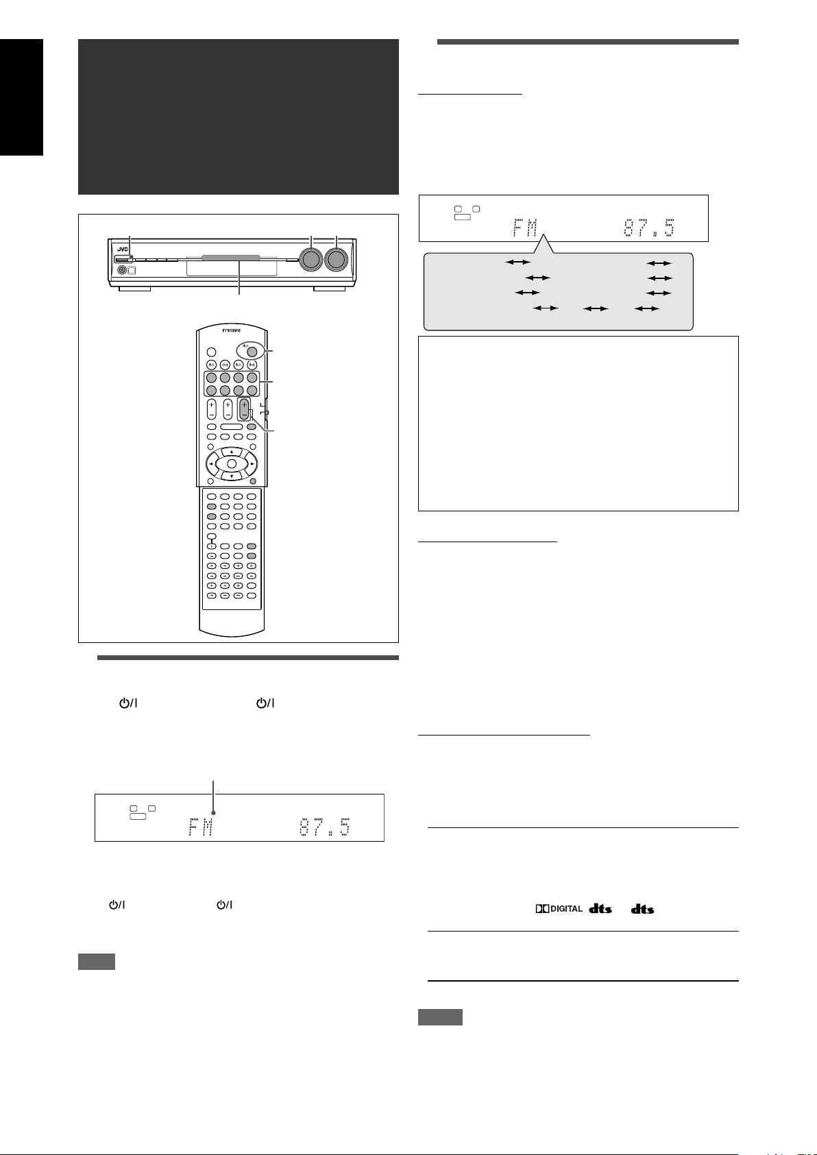
Parts identification
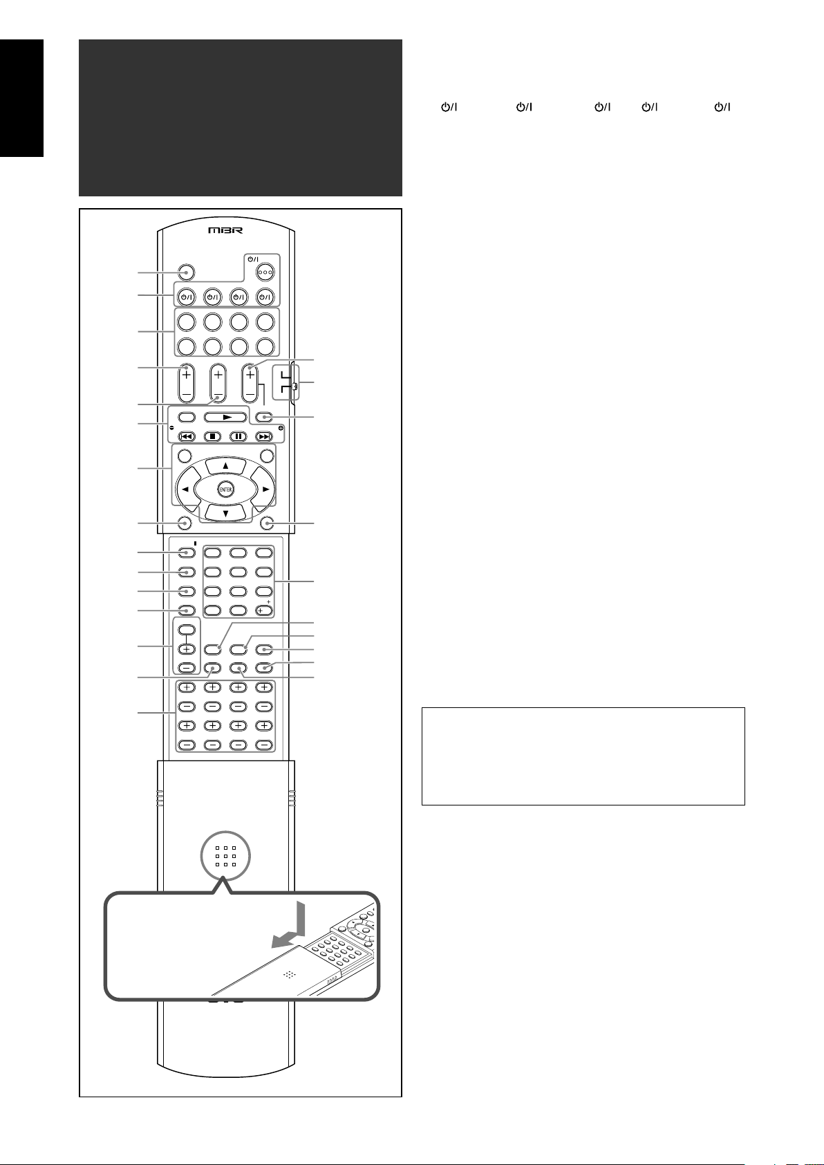
Remote control
See pages in parentheses for details.
1 TV/VIDEO button (36, 38)
2 Standby/on buttons (14, 36 – 40)
AUDIO, TV , DBS/CATV , VCR , DVR/DVD
3 Source selecting buttons (14, 27, 36 – 40)
TV, DBS, VCR, DVR/DVD, FM, AM, USB, DVD MULTI
4 TV VOL (volume) +/– button (36, 38)
5 CHANNEL +/– button (36 – 40)
6 • Operating buttons for video components (36, 37, 39, 40)
REC PAUSE, REW, FF, 3, 4, 7, 8, ¢
• Operating buttons for tuner (27, 28)
FM MODE, ( TUNING, MEMORY, TUNING 9
7 Operating buttons for DVD recorder or DVD player* (37, 40)
TOP MENU, MENU, cursor buttons (3, 2, 5, ∞), ENTER
8 SURROUND button (33)
9 EX/ES/PLIIx button (20)
p ANALOG/DIGITAL button (14)
q DECODE MODE button (15)
w MIDNIGHT button (21)
e Adjusting buttons for Digital Equalizer (24)
D.EQ FREQ, D.EQ LEVEL +/–
r B (bass).BOOST button (25)
t Adjusting buttons for speaker and subwoofer output levels (24)
FRONT L +/–, FRONT R +/–, CENTER +/–, SUBWFR +/–,
SURR L +/–, SURR R +/–, S.BACK L +/–, S.BACK R +/–
y VOLUME +/– button (15)
u DVR/DVD mode selector (37, 40)
i MUTING button (15)
o CC CONVERTER button (16)
; • Numeric buttons (28, 36 – 40)
1 – 10, 0, +10, 100+
• RETURN button (36)
a C (center).TONE button (26)
s EFFECT button (25)
d DIMMER button (16)
f SLEEP button (16)
g TEST button (24)
* These buttons can be used for operating a JVC DVD recorder
or DVD player with the mode selector set to “DVR ” or “DVD”
(see page 37).
If these buttons do not function normally, use the remote control
supplied with your DVD recorder or DVD player. Refer also to
the manuals supplied with the DVD recorder or DVD player for
details.
• When operating a DVD recorder (for JVC products
ONLY), set the mode selector (u) to “DVR.”
• When operating a DVD player, set the mode selector (u)
to “DVD.”
To open the cover of the remote
control, push here then slide
downward
2
Page 5
See pages in parentheses for details.
DIGITAL EQ
LINEAR PCM
L
LSSBRS
S.WFR
PL
NEO : 6
DSP
3D-PHONIC
LFE
CR
96 / 24
AUTO SURR
C.TONE
VIRTUAL SB
B.BOOST
TUNED
STEREO
SLEEP
AUTO MUTING
INPUT ATT
HEADPHONE
MHz
kHz
x
MIDNIGHT
DIGITAL
DIGITAL AUTO
ANALOG
DUAL MONO
SBSSB
ONE TOUCH OPERATION
CC CONVERTER 1 2
1
2
3
5
87
^
#
$
!
@
=
~
%
4
6
-
0
9
&
*
(
)
AUDIO/VIDEO CONTROL RECEIVER
STANDBY/ON
CC CONVERTER
SETTING ADJUST SURROUND
DVR / DVD VCR DBS TV USB FM
SOURCE
SELECTOR
/ MULTI JOG
MASTER
VOLUME
SET / TUNER PRESET
PHONES USB
AM
DVD MULTI
45 6
q
e
78 9
p
321
w
AV
COMPU LINK-
III
Y
P
B
P
R
COMPONENT VIDEO
VIDEO
AUDIO
MONITOR
OUT
DVR/DVD
IN
TV
IN
DBS
IN
OUT(REC) IN(PLAY)
VCR DVR
OUT(REC)
DVR/DVD
IN(PLAY)
VCR(DBS)
IN
MONITOR
OUT
DVR
OUT(REC)
VCR
OUT(REC) IN(PLAY)
DBS
IN
DVR/DVD
IN(PLAY)
VIDEO
S-VIDEO
L
R
DIGITAL IN
2(DBS)
1(DVR/DVD)
LEFTRIGHT LEFTRIGHT
LEFTRIGHT
ANTENNA
COAXIAL
AM LOOP
FM 75
AM EXT
SUBWOOFER
OUT
3(VCR)
DIGITAL OUT
PCM/STREAM
SURROUND
SPEAKERS
ANTENNA
USB WIRELESS
CAUTION:SPEAKER
IMPEDANCE 6
-
16
SURROUND BACK
SPEAKERS
DVD
MULTI IN
FRONT
CENTER
SUBWOOFER
SURR-L
SURR-R
CENTER
SPEAKER
FRONT
SPEAKERS
q
LEARNING
IDON
123
6
7
89p w
4
5
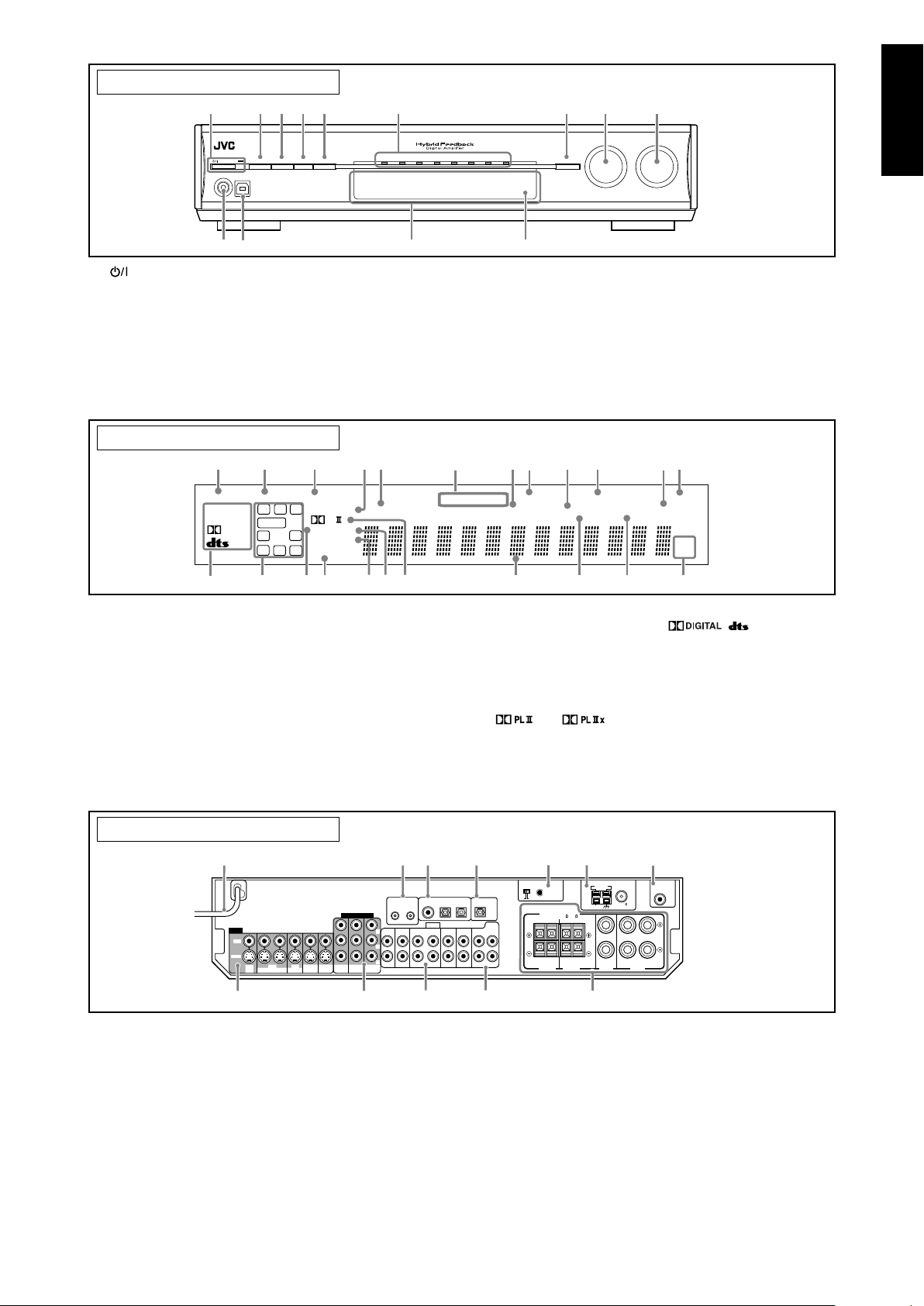
Front panel
English
1 STANDBY/ON button and standby lamp (14)
2 CC CONVERTER button (16)
3 SETTING button (17, 19)
4 ADJUST button (23)
5 SURROUND button (33)
6 Source lamps
DVD MULTI, DVR/DVD, VCR, DBS, TV, USB, FM, AM
7 • SET button (17, 19, 23)
• TUNER PRESET button (28)
Display window
1 ANALOG indicator (14)
2 DUAL MONO indicator (21)
3 AUTO SURR (surround) indicator (33)
4 HEADPHONE indicator (15, 30)
5 CC CONVERTER 1 2 indicator (16)
6 Tuner operation indicators (27)
TUNED, STEREO
7 DIGITAL EQ indicator (24)
8 AUTO MUTING indicator (28)
9 C.TONE indicator (26)
0 ONE TOUCH OPERATION indicator (22)
- INPUT ATT (attenuate) indicator (25)
= SLEEP indicator (16)
8 • SOURCE SELECTOR (14, 28)
• MULTI JOG (17, 19, 23, 28, 33)
9 MASTER VOLUME control (15)
p PHONES jack (15)
q USB terminal (12)
w Display window (see below)
e Remote sensor (4)
~ Digital signal format indicators (15, 29, 30)
DIGITAL AUTO, LINEAR PCM, , , 96/24
! Signal and speaker indicators (16)
@ NEO:6 indicator (30)
# VIRTUAL SB indicator (32)
$ 3D-PHONIC indicator (30, 31)
% DSP indicator (30, 31)
^ and indicator (29 – 31)
& Main display
* B (bass).BOOST indicator (25)
( MIDNIGHT indicator (21)
) Frequency unit indicators
MHz (for FM stations), kHz (for AM stations)
Rear panel
1 Power cord (11)
2 AV COMPU LINK-III terminals (34)
3 DIGITAL IN terminals (11)
• Coaxial: 1(DVR/DVD)
• Optical: 2(DBS)
• Optical: 3(VCR)
4 DIGITAL OUT terminal (11)
5 USB WIRELESS ANTENNA terminal (12)
6 ANTENNA terminals (5)
7 SUBWOOFER OUT jack (6)
8 VIDEO jacks (7– 10)
VIDEO (composite video) jacks, S-VIDEO jacks
• Input: DBS IN, VCR IN (PLAY), DVR/DVD IN (PLAY)
• Output: VCR OUT (REC), DVR OUT (REC), MONITOR OUT
9 COMPONENT VIDEO (Y, PB, PR) jacks (7– 10)
VCR (DBS) IN, DVR/DVD IN, MONITOR OUT
p AUDIO jacks (7 – 10)
• Input: TV IN, DBS IN, VCR IN (PLAY), DVR/DVD IN (PLAY)
• Output: VCR OUT (REC), DVR OUT (REC)
q DVD MULTI IN jacks (8)
CENTER, SUBWOOFER, SURR – L, SURR – R
w Speakers terminals (6)
SURROUND BACK SPEAKERS, SURROUND SPEAKERS,
CENTER SPEAKER, FRONT SPEAKERS
3
Page 6
English
123
Getting started
Before Installation
General precautions
• Be sure your hands are dry.
• Turn the power off to all components.
• Read the manuals supplied with the components you are going
to connect.
Locations
• Install the receiver in a location that is level and protected from
moisture and dust.
• The temperature around the receiver must be between –5˚C
and 35˚C.
• Make sure there is good ventilation around the receiver. Poor
ventilation could cause overheating and damage the receiver.
• Leave sufficient distance between the receiver and the TV.
Handling the receiver
• Do not insert any metal object into the receiver.
• Do not disassemble the receiver or remove screws, covers, or
cabinet.
• Do not expose the receiver to rain or moisture.
• Do not pull on the power cord to unplug the cord. When
unplugging the cord, always grasp the plug so as not to damage
the cord.
• When you are away on travel or otherwise for an extended
period or time, remove the plug from the wall outlet. A small
amount of power is always consumed while the power cord is
connected to the wall outlet.
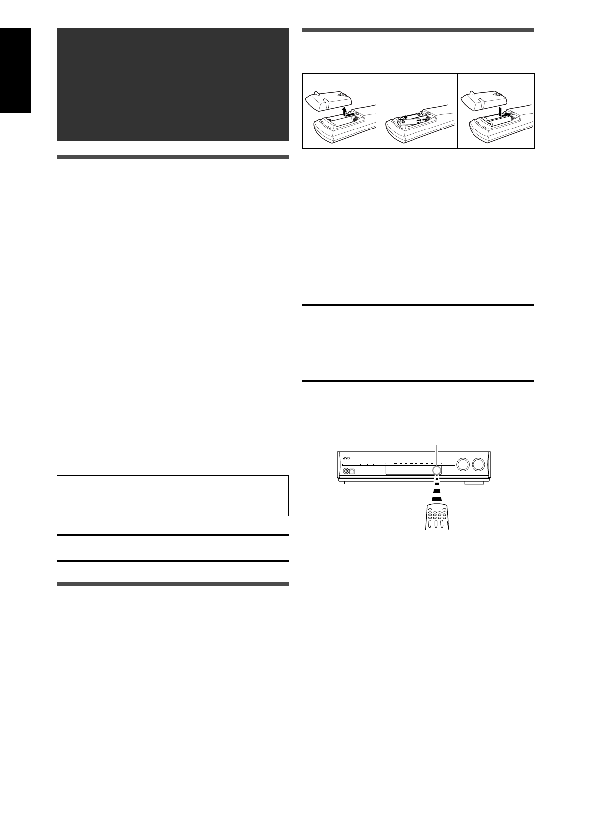
Putting batteries in the remote control
Before using the remote control, put two supplied batteries first.
1
Press and slide the battery cover on the back
of the remote control.
2
Insert batteries.
Make sure to match the polarity: (+) to (+) and (–) to (–).
3
Replace the cover.
If the range or effectiveness of the remote control decreases,
replace the batteries. Use two R6(SUM-3)/AA(15F) type dry-cell
batteries.
• Supplied butteries are for initial setup. Replace for continued
use.
CAUTION:
Follow these precautions to avoid leaking or cracking cells:
• Place batteries in the remote control so they match the polarity:
(+) to (+) and (–) to (–).
• Use the correct type of batteries. Batteries that look similar may
differ in voltage.
• Always replace both batteries at the same time.
• Do not expose batteries to heat or flame.
When using the remote control, aim the remote control directly at
the remote sensor on the front panel.
Remote sensor
The receiver has a built-in cooling fan which operates
while the receiver is turned on. Be sure to leave enough
ventilation to obtain sufficient cooling effect.
CAUTION:
Do not connect the AC power plug to the wall outlet until all
connections are completed.
Checking the supplied accessories
Check to be sure you have all of the following supplied
accessories. If anything is missing, contact your dealer
immediately.
• Remote control (× 1)
• Batteries (× 2)
• AM loop antenna (× 1)
• FM antenna (× 1)
• USB wireless antenna (× 1)
• USB wireless transmitter (Model number: QAL0708-001) (× 1)
• USB extension cable (60 cm) (× 1)
4
Page 7
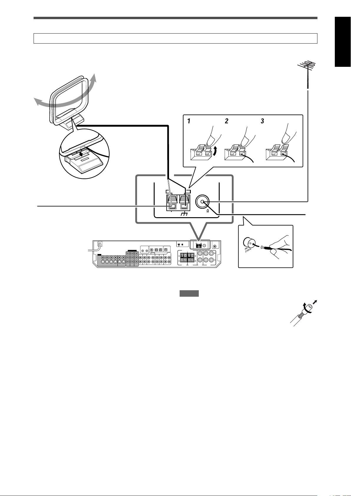
Connecting the FM and AM antennas
ANTENNA
COAXIAL
FM 75
AM EXT
AM LOOP
ANTENNA
Do not connect the AC power plug to the wall outlet until all connections are completed.
AM loop antenna
(supplied)
Snap the tabs on the
loop into the slots of
the base to assemble
the AM loop antenna.
English
If FM reception is poor, connect an
outdoor FM antenna (not supplied).
If AM reception is poor, connect
an outdoor single vinyl-covered
wire (not supplied).
AM antenna connection
Connect the AM loop antenna supplied to the AM LOOP terminals.
Connect the white cord to the AM EXT terminal, and connect the
black cord to the H terminal.
Turn the loop until you have the best reception.
• If the reception is poor, connect an outdoor single vinyl-covered
wire (not supplied) to the AM EXT terminal. Keep the AM loop
antenna connected.
FM antenna connection
Connect the FM antenna supplied to the FM 75 Ω COAXIAL
terminal as a temporary measure.
Extend the supplied FM antenna horizontally.
• If the reception is poor, connect an outdoor FM antenna (not
supplied). Before attaching a 75 Ω coaxial cable with a
connector, disconnect the supplied FM antenna.
FM antenna (supplied)
NOTES
• If the AM loop antenna wire is covered with vinyl,
remove the vinyl while twisting it as shown on the
right.
• Make sure the antenna conductors do not touch
any other terminals, connecting cords and power
cord. This could cause poor reception.
5
Page 8
L
R
LS
RS
SBL
C
SW
SBR
(*SB)
LEFTRIGHT LEFT
RIGHT
LEFTRIGHT
SUBWOOFER
OUT
SURROUND
SPEAKERS
CAUTION:SPEAKER
IMPEDANCE 6
-
16
SURROUND BACK
SPEAKERS
CENTER
SPEAKER
FRONT
SPEAKERS
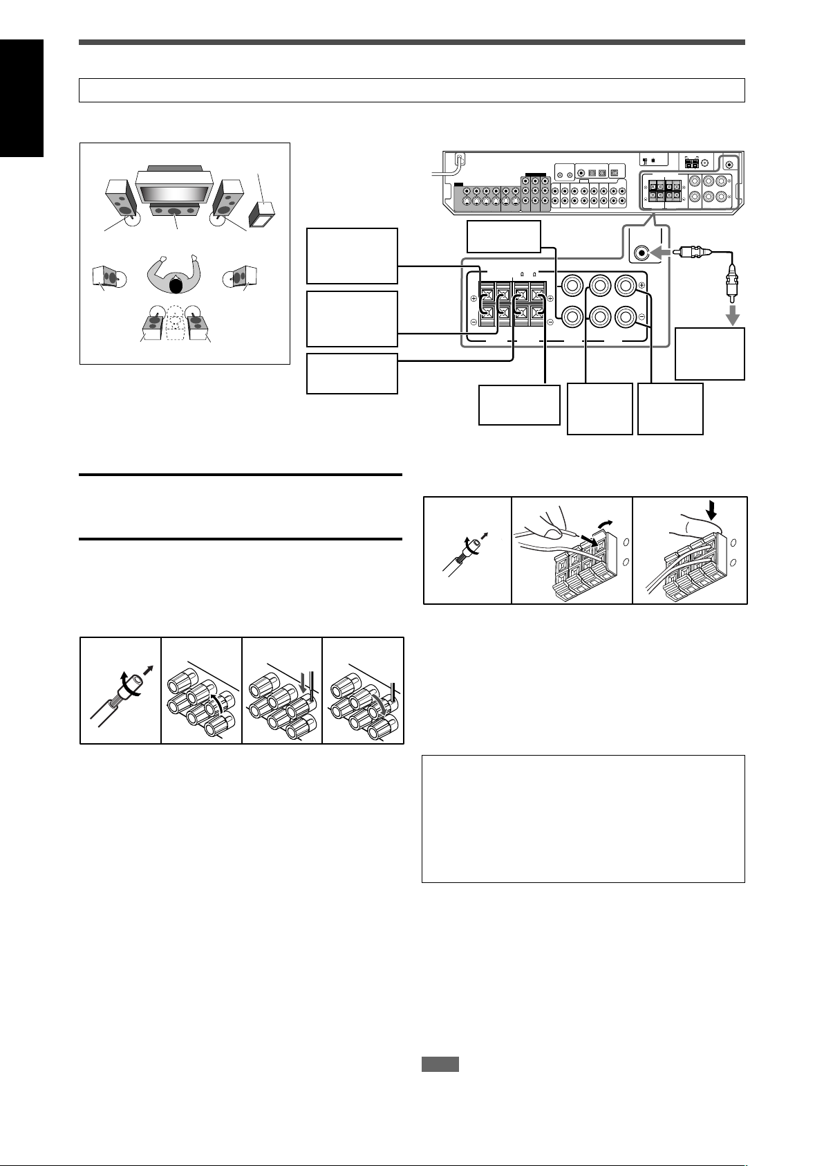
Connecting the speakers
1324
12 3
+
–
1
2
+
–
Do not connect the AC power plug to the wall outlet until all connections are completed.
English
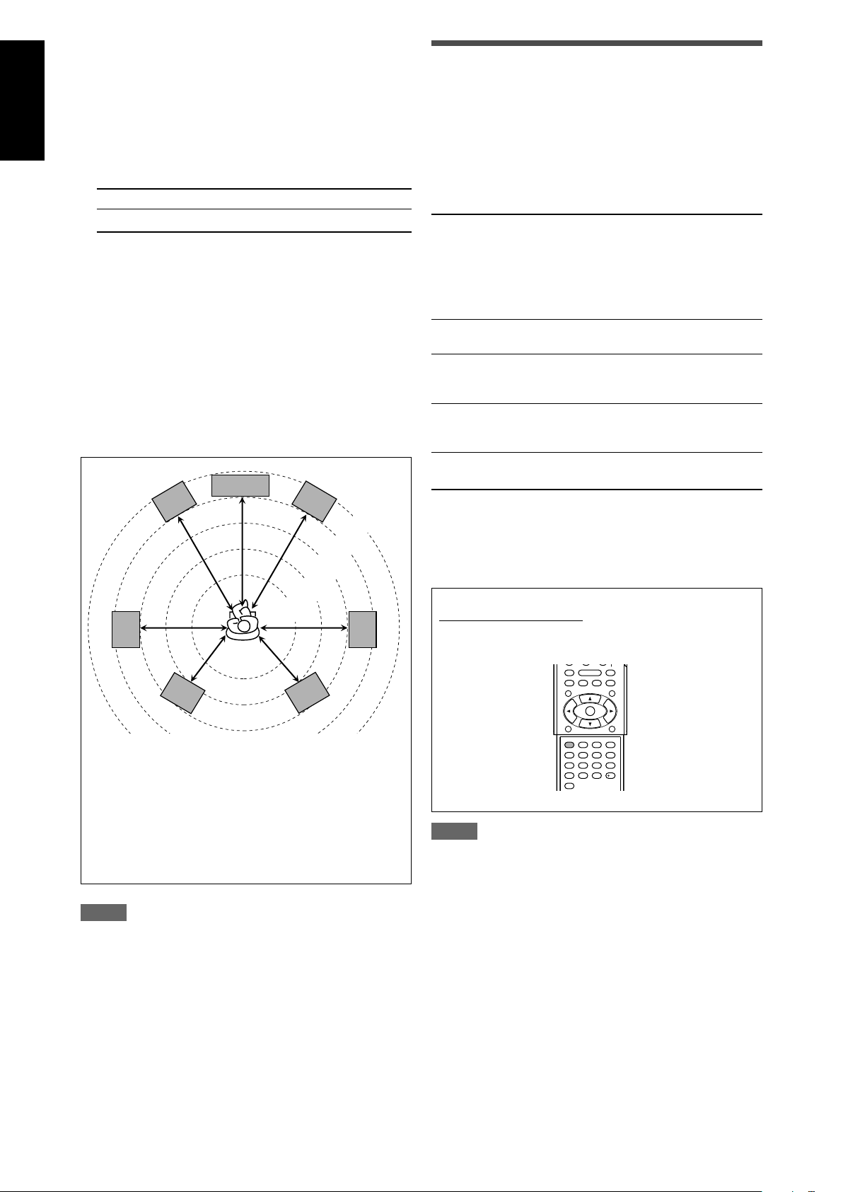
Speaker Layout Diagram
Right surround
back speaker
(SBR)
*Left surround
back speaker
(SBL)
Right surround
speaker (RS)
CAUTIONS:
• Use speakers with the SPEAKER IMPEDANCE indicated by the
speaker terminals (6 Ω – 16 Ω).
• DO NOT connect more than one speaker to one speaker
terminal.
Center
speaker (C)
Powered
subwoofer
(SW)
Left surround
speaker (LS)
Right front
speaker
(R)
Left front
speaker
(L)
Connecting the surround speakers and the surround back
speakers
Connecting the speakers
Turn off all components before making connections.
Connecting the center speaker and the front speakers
1
Twist and remove the insulation at the end of each
speaker cord.
2
Turn the knob counterclockwise.
3
Insert the speaker cord.
• For each speaker, connect the (+) and (–) terminals on the
rear panel to the (+) and (–) terminals marked on the
speakers.
4
Turn the knob clockwise.
6
1
Twist and remove the insulation at the end of each
speaker cord.
2
Open the terminal (1), then insert the speaker cord
(2).
• For each speaker, connect the (+) and (–) terminals on the
rear panel to the (+) and (–) terminals marked on the
speakers.
3
Close the terminal.
*When using a single speaker for the surround back speaker
You can enjoy the surround sound by one surround back
speaker. When using one surround back speaker,
– set “SB OUT” to “<1SPK>” (see page 19) and
– connect the surround back speaker to the left surround back
speaker terminal. (No sound comes from the speaker if
you connect it to the right surround back speaker
terminal.)
Connecting the powered subwoofer
By connecting a subwoofer, you can enhance the bass or
reproduce the original LFE signals recorded in digital software.
Connect the input jack of a powered subwoofer to the
SUBWOOFER OUT jack on the rear panel, using a cord
with RCA pin plugs (not supplied).
• Refer also to the manual supplied with your subwoofer.
After connecting all the speakers and/or a subwoofer, set the
speaker setting information properly to obtain the best possible
surround effect. For details, see pages 17 to 21.
NOTE
You can place a subwoofer wherever you like since bass sound is
non-directional. Normally place it in front of you.
Page 9
ı
ΉÏÌ
Ç
Å
DVR
OUT(REC)
DVR/DVD
IN(PLAY)
Y
P
B
P
R
COMPONENT VIDEO
MONITOR
OUT
DVR/DVD
IN
VCR(DBS)
IN
DVR
OUT(REC)
DVR/DVD
IN(PLAY)
FRONT
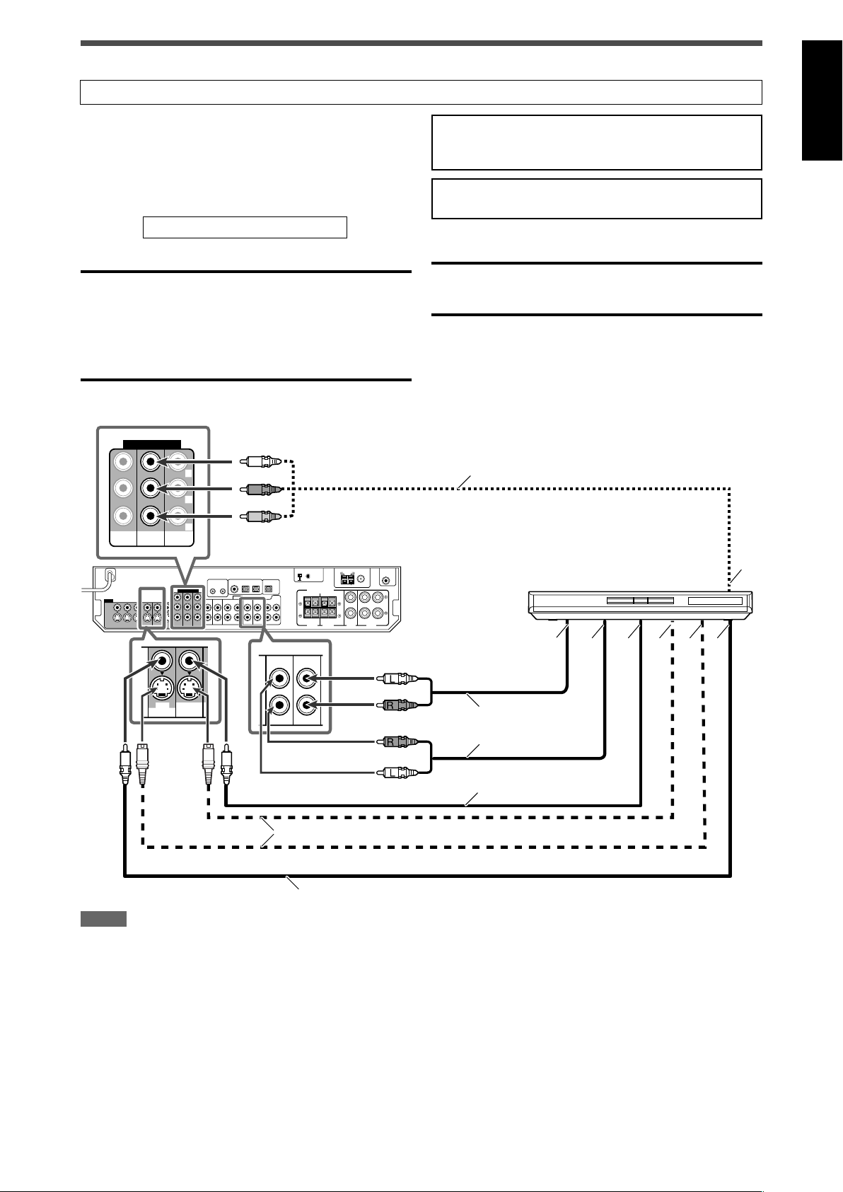
Connecting video components
Do not connect the AC power plug to the wall outlet until all connections are completed.
This receiver is equipped with the following video terminals—
composite video, S-video, and component video terminals.
• If your video components have S-video (Y/C-separation) and/or
component video (Y, PB, PR) jacks, connect them using an S-
Turn off all components before making connections.
• When you connect other components, refer also to their
manuals.
video cable (not supplied) or component video cable (not
supplied). By using these terminals, you can get a better picture
quality in the order:
DO NOT use a TV through a VCR or a TV with a built-in
VCR; otherwise, the picture may be distorted.
Component > S-video > Composite
IMPORTANT:
This receiver can convert video signals as follows:
• Composite video signals can be converted into both S-video
signals and component signals.
CAUTION:
If you connect a sound-enhancing device such as a graphic
equalizer between the source components and this receiver, the
sound output through this receiver may be distorted.
• S-video signals can be converted into component signals.
• Component signals cannot be converted.
When converting video signals, there are some points to observe.
For details, see “About video signal conversion” on page 11.
If your video components have AV COMPU LINK terminal
See also page 34 for detailed information about the connection
and the AV COMPU LINK remote control system.
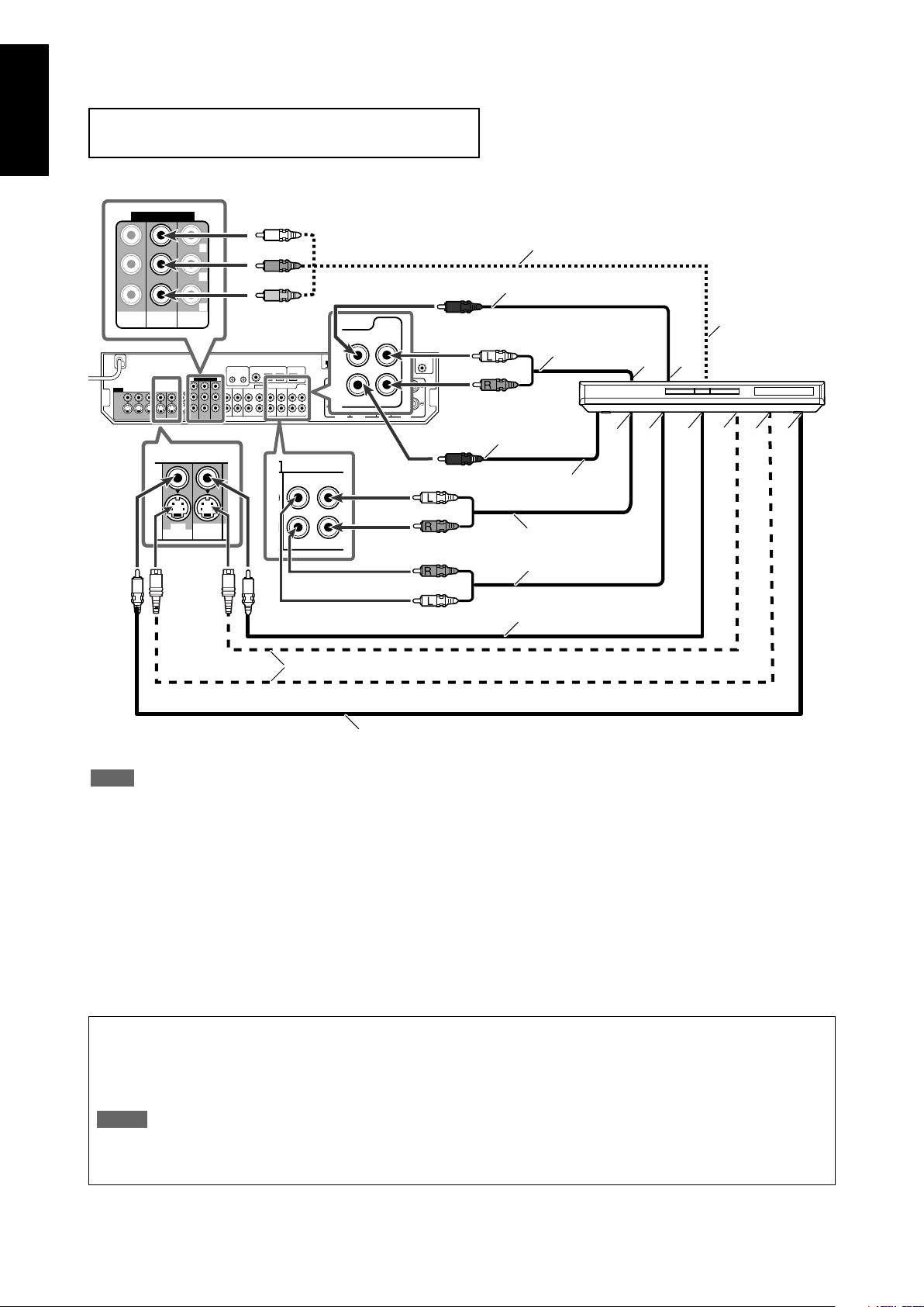
7 Connecting a DVD recorder or DVD player with its stereo output jacks:
Green
Component video cable (not supplied)
Blue
Red
English
White
Red
Red
White
S-video cable (not supplied)
Composite video cable (not supplied)
NOTES
• Select the analog input mode. See “Selecting the analog or
digital input mode” on page 14.
• When connecting a DVD recorder or DVD player to the
component video input jacks, select the component video input
mode (DVD VIDEO IN) correctly. If you do not, you cannot view
the playback picture on the TV or the AV COMPU LINK remote
control system cannot operate properly. See page 22 for details.
• You can enjoy digital sound if using a digital coaxial or optical
cable. When shipped from the factory, the audio input mode for
a DVD recorder and DVD player is set to use the digital coaxial
terminal (DIGITAL IN 1 (DVR/DVD)). For details of digital
connection, see page 11.
DVD recorder or
DVD player
Stereo audio cable
(not supplied)
Composite video cable
(not supplied)
Å To component video output
• Connect Y, P
ı To left/right audio channel output
Ç Only for DVD recorder: To left/right audio channel
input
Î To composite video output
‰ To S-video output
Ï Only for DVD recorder: To S-video input
Ì Only for DVD recorder: To composite video input
B, and PR correctly.
7
Page 10
English
Å
Ï
Ó
ı
Ç
Î
‰
Ì
Ô
DVR
OUT(REC)
DVR/DVD
IN(PLAY)
DVR
OUT(REC)
DVR/DVD
IN(PLAY)
FRONT
COMPONENT VIDEO
MONITOR
OUT
DVR/DVD
IN
VCR(DBS)
IN
DVD
MULTI IN
CENTER
SUBWOOFER
SURR-L
SURR-R
È
Y
P
B
P
R
7 Connecting a DVD recorder or DVD player with its analog discrete output jacks (DVD MULTI IN):
This connection is the best connection method for enjoying DVD Audio sounds. When a DVD Audio disc is played back, the original highquality sounds can be reproduced only using this connection.
Turn off all components before making connections.
• When you connect other components, refer also to their manuals.
Green
Component video cable (not supplied)
Blue
Red
S-video cable (not supplied)
Monaural audio cable
(not supplied)
White
Red
Red
White
Monaural audio cable
(not supplied)
Stereo audio cable
(not supplied)
Stereo audio cable
(not supplied)
Composite video cable
(not supplied)
DVD recorder or
DVD player
Composite video cable (not supplied)
NOTE
When connecting a DVD recorder or DVD player to the
component video input jacks, select the component video input
mode (DVD VIDEO IN) correctly. If you do not, you cannot view
the playback picture on the TV or the AV COMPU LINK remote
control system cannot operate properly. See page 22 for details.
Å To left/right surround channel audio output
ı To center channel audio output
Ç To component video output
• Connect Y, P
B, and PR correctly.
Î To subwoofer output
‰ To left/right front channel audio output
Ï Only for DVD recorder: To left/right front channel
audio input
Ì To composite video output
Ó To S-video output
È Only for DVD recorder: To S-video input
Ô Only for DVD recorder: To composite video input
About “DVD MULTI”
When you select “DVD MULTI” as the source (see page 14), you can enjoy analog discrete output sound (5.1-channel reproduction)
from the connected component.
• You may need to select analog discrete output mode on the component.
NOTES
• When using the headphones, you can listen to the front channel sounds (left and right) only. 3D HEADPHONE mode (see page 30)
is not available.
• Surround/DSP modes (see pages 29 to 33) are not available for “DVD MULTI.”
8
Page 11
Do not connect the AC power plug to the wall outlet until all connections are completed.
VCR
OUT(REC) IN(PLAY)
AUDIO
OUT(REC) IN(PLAY)
VCR
Å
ı
ΉÏÌÇ
Y
P
B
P
R
COMPONENT VIDEO
MONITOR
OUT
DVR/DVD
IN
VCR(DBS)
IN
Å
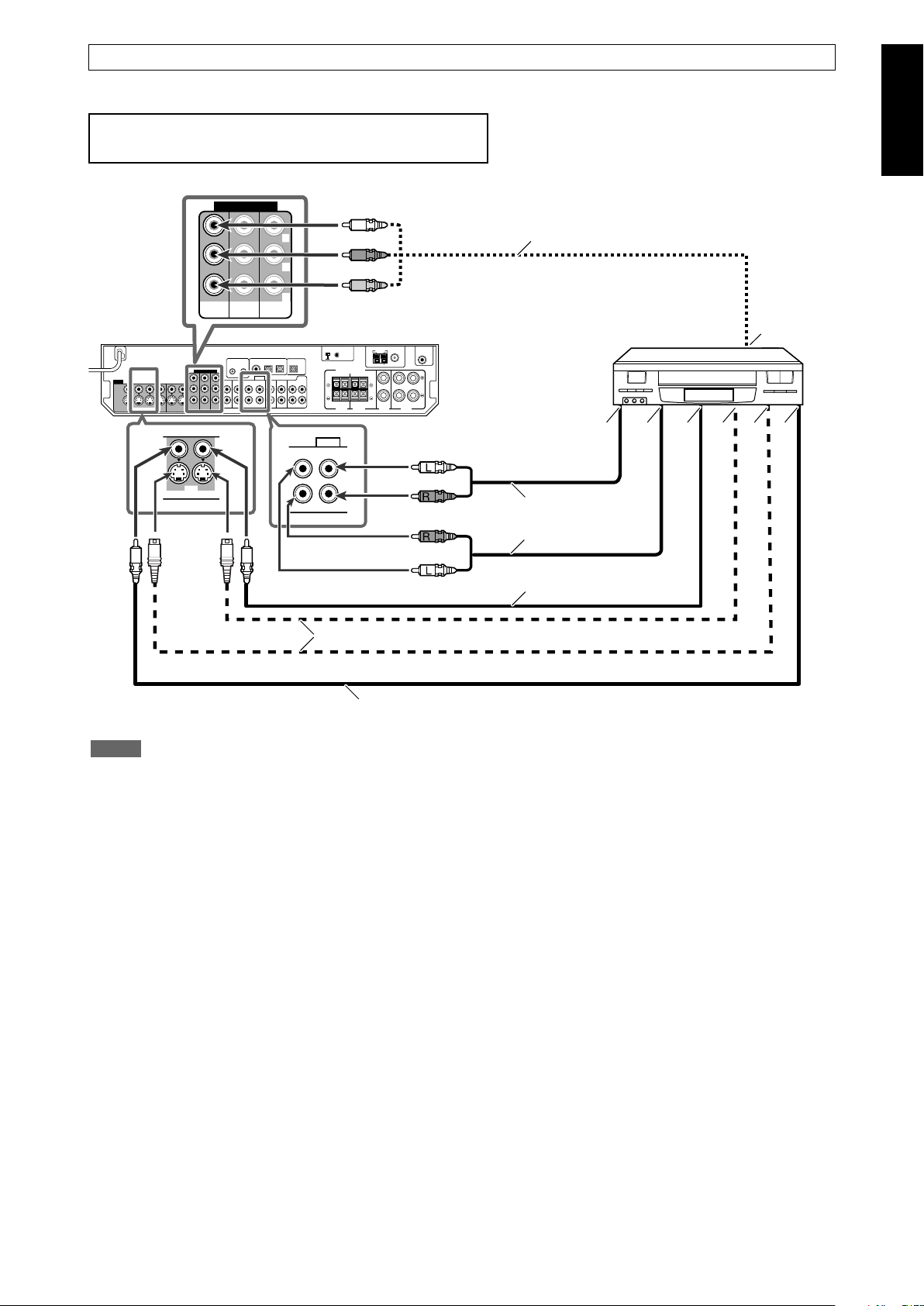
7 Connecting a VCR
Turn off all components before making connections.
• When you connect other components, refer also to their manuals.
Green
Blue
Red
White
Red
Red
English
Component video cable (not supplied)
VCR
Stereo audio cable
(not supplied)
White
S-video cable (not supplied)
Composite video cable (not supplied)
NOTES
• Select the analog input mode. See “Selecting the analog or
digital input mode” on page 14.
• When connecting a VCR to the component video input jacks,
select the component video input mode (VCR VIDEO IN)
correctly. If you do not, you cannot view the playback picture on
the TV or the AV COMPU LINK remote control system cannot
operate properly. See page 22 for details.
• You can enjoy digital sound if using a digital coaxial or optical
cable. When shipped from the factory, the audio input mode for
a VCR is set to use the digital optical terminal (DIGITAL IN 3
(VCR)). For details of digital connection, see page 11.
Composite video
cable (not supplied)
Å To component video output
• Connect Y, P
B, and PR correctly.
ı To left/right audio channel output
Ç To left/right audio channel input
Î To composite video output
‰ To S-video output
Ï To S-video input
Ì To composite video input
9
Page 12
Do not connect the AC power plug to the wall outlet until all connections are completed.
COMPONENT VIDEO
MONITOR
OUT
DVR/DVD
IN
VCR(DBS)
IN
Y
P
B
P
R
U
Å
ı
ÎÇ
Å
ı
Î
Ç
Y
P
B
P
R
COMPONENT VIDEO
MONITOR
OUT
DVR/DVD
IN
VCR(DBS)
IN
B
N
/
English
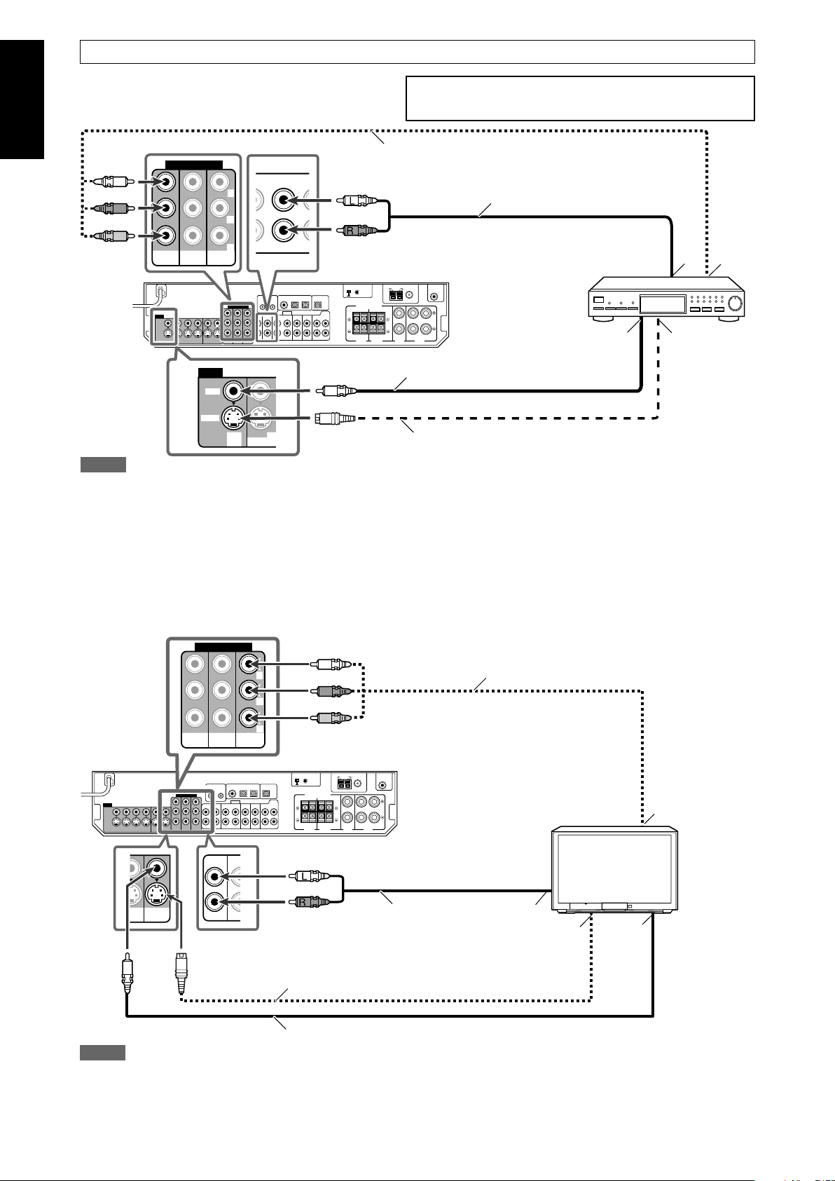
7 Connecting a DBS tuner
Turn off all components before making connections.
• When you connect other components, refer also to their manuals.
Component video cable (not supplied)
Green
Blue
Red
VIDEO
VIDEO
S-VIDEO
DBS
IN
NOTES
• Select the analog input mode. See “Selecting the analog or digital input mode” on
page 14.
OUT(REC)
VC
DBS
IN O
White
Red
Stereo audio cable (not supplied)
Composite video cable (not supplied)
S-video cable (not supplied)
• When connecting a DBS tuner to the component video input jacks, select the
component video input mode (DBS VIDEO IN) correctly. If you do not, you cannot
view the playback picture on the TV. See page 22 for details.
• You can enjoy digital sound if using a digital coaxial or optical cable. When shipped
from the factory, the audio input mode for a DBS tuner is set to use the digital optical
terminal (DIGITAL IN 2 (DBS)). For details of digital connection, see page 11.
DBS tuner
Å To left/right audio channel output
ı To component video output
• Connect Y, P
B, and PR correctly.
Ç To composite video output
Î To S-video output
7 Connecting a TV
Connect the TV to the appropriate MONITOR OUT jacks to view the playback picture from any other connected video components.
Green
Blue
Component video cable (not supplied)
Red
TV
TVIND
I
L
MONITOR
DVD
LAY)
OUT
R
White
Red
Stereo audio cable
(not supplied)
S-video cable (not supplied)
Composite video cable (not supplied)
NOTES
• Select the analog input mode. See “Selecting the analog or digital input mode” on
page 14.
• You can enjoy digital sound if using a digital coaxial or optical cable. For details of
digital connection, see page 11.
Å To component video input
• Connect Y, PB, and PR correctly.
ı To left/right audio channel output
Ç To S-video input
Î To composite video input
10
Page 13
DIGITAL OUT
PCM/STREAM
DIGITAL IN
2(DBS)
1(DVR/DVD)
3(VCR)
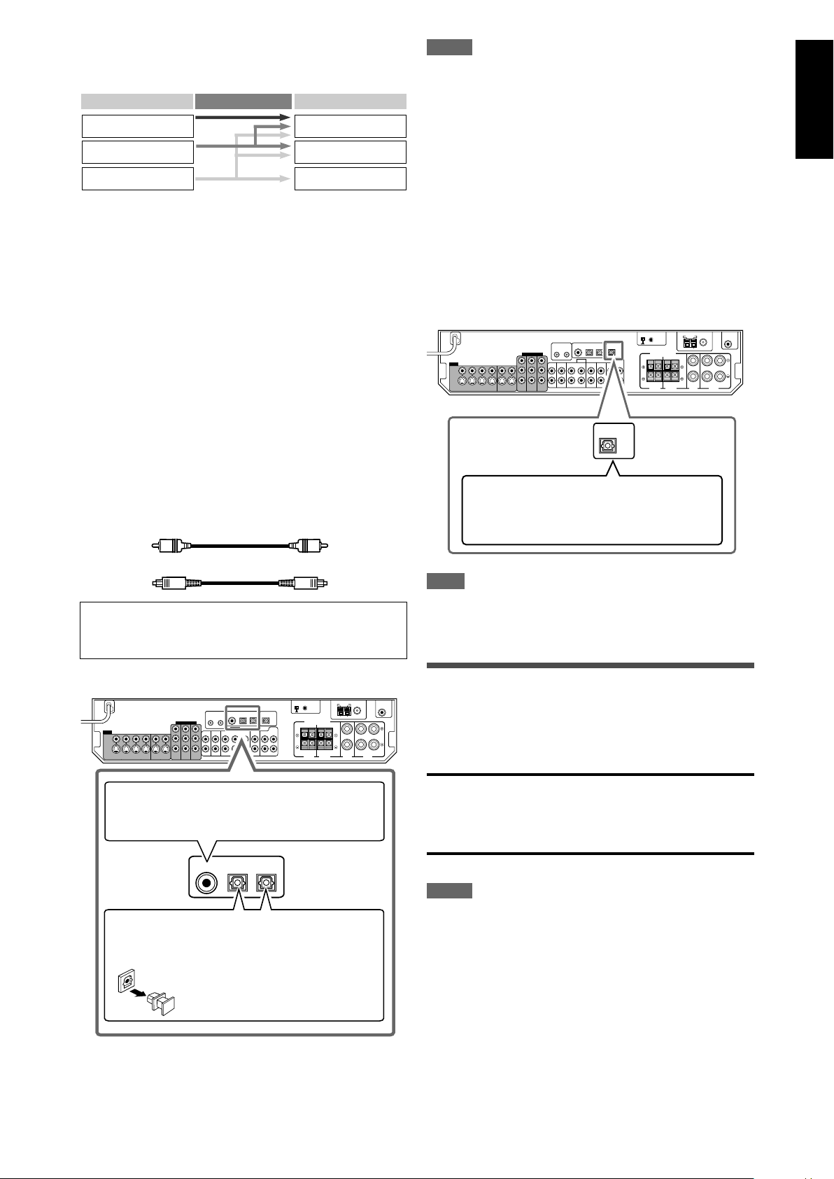
About video signal conversion
Video Input Converted Video Output
Component
S-video
Video (composite)
Component
S-video
Video (composite)
This receiver can convert video signals. See the table below about
video signal conversion.
To convert composite video and S-video signal into component
video signal, set the “DVD VIDEO IN,” “VCR VIDEO IN,” or “DBS
VIDEO IN” to “<S/C>” (see page 22).
• If using composite video cable for connecting to the video input
and using S-video cable for connecting to the video output, the
video signal is converted into S-video signal automatically.
•Even if the recording components are connected to the receiver
using the S-video cords and the playpack components are
connected to the receiver using the composite video cords, you
can record the picture on TV.
• Pictures may be distorted if the signals are converted. If this
happens, connect the playback source component and TV using
the cords of the same type.
• Incoming signal of component can be emitted only through the
component output jacks.
Digital connection
This receiver is equipped with three DIGITAL IN terminals—one
digital coaxial terminal and two digital optical terminals—and one
DIGITAL OUT terminal.
To reproduce the digital sound, use the digital connection in
addition to the analog connection methods described on pages 7
to 10.
Digital coaxial cable (not supplied)
NOTES
• When shipped from the factory, the DIGITAL IN terminals have
been set for use with the following components:
– 1(DVR/DVD): For DVD recorder or DVD player
– 2(DBS): For DBS tuner
– 3(VCR): For VCR
If you connect other components, change the digital input
(DIGITAL IN) terminal setting correctly. See “Setting the digital
input (DIGITAL IN) terminals—DIGITAL IN 1/2/3” on page 22.
• Select the correct digital input mode. See “Selecting the analog
or digital input mode” on page 14.
• When you want to operate the connected component (except
DBS tuner) using the AV COMPU LINK remote control system
(see pages 34 and 35), connect them also as described on
pages 7 to 10.
7 Digital output terminal
You can connect any digital components which have an optical
digital input terminal.
Connecting digital recording equipment to the
DIGITAL OUT terminal enables you to perform
digital-to-digital recording.
English
Digital optical cable (not supplied)
Turn off all components before making connections.
• When you connect other components, refer also to their
manuals.
7 Digital input terminals
When the component has a digital coaxial output
terminal, connect it to the 1(DVR/DVD) terminal,
using a digital coaxial cable (not supplied).
When the component has a digital optical output
terminal, connect it to the 2(DBS) or 3(VCR)
terminal, using a digital optical cable (not supplied).
Before connecting a digital
optical cable, unplug the
protective plug.
NOTE
The digital signal format transmitted through the DIGITAL OUT
terminal is the same as that of the input signal. For example,
when the DTS signals are input, the DTS signals are transmitted.
Connecting the power cord
When all the audio/video connections have been made, connect
the AC power plug to the wall outlet. Make sure that the plugs are
inserted firmly. The standby lamp lights in red.
CAUTIONS:
• Do not touch the power cord with wet hands.
• Do not alter, twist or pull the power cord, or put anything heavy
on it, which may cause fire, electric shock, or other accidents.
• If the cord is damaged, consult a dealer and have the power
cord replaced with a new one.
NOTES
•Keep the power cord away from the connecting cables and the
antenna. The power cord may cause noise or screen
interference.
• The preset settings such as preset channels and sound
adjustment may be erased in a few days in the following cases:
– When you unplug the power cord.
– When a power failure occurs.
• When you unplug the power cord with the receiver on and
connect the power cord again, the receiver enters standby
mode.
11
Page 14
English
ANTENNA
USB WIRELESS
LEARNING
IDON
USB
USB WIRELESS TRANSMITTER
IDCHANNEL
POWER PLAYERID
USB WIRELESS TRANSMITTER
POWER PLAYERID
USB WIRELESS TRANSMITTER
USB Connection
This receiver is equipped with a USB terminal on the front panel
and a USB WIRELESS ANTENNA terminal on the rear. You can
enjoy sound reproduced through your PC with either of the
following methods:
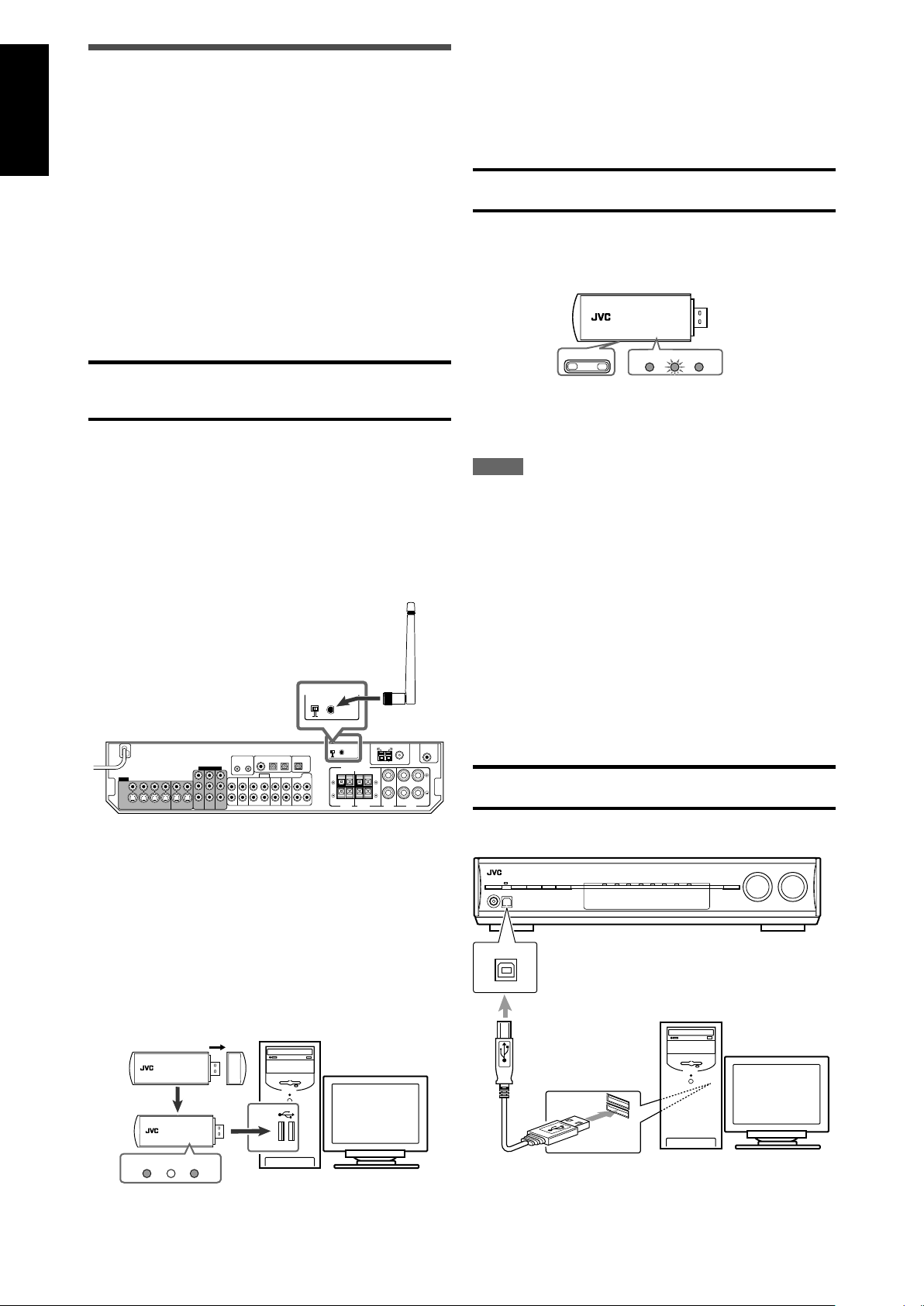
1 connecting a USB wireless antenna (supplied) to the USB
WIRELESS ANTENNA terminal and a USB wireless
transmitter (supplied) to your PC. (USB WIRELESS)
2 connecting your PC to the USB terminal with a USB cable (not
supplied). (USB TERMINAL)
When you connect your PC for the first time, follow the procedure
below.
• Remember you cannot send any signal or data to your PC from
this receiver.
• Use USB extension cable (supplied) if it is difficult to connect
the transmitter directly to the USB connector or the transmitter
becomes obstacle to other USB connectors.
IMPORTANT:
Check if your PC equipped with the CD-ROM drive is running on
Windows® 98 SE*, Windows® Me*, Windows® 2000* or Windows
XP* and prepare its CD-ROM.
Preparation
1 (For USB WIRELESS)
Be sure to make USB WIRELESS communication
before connection and installation of the receiver.
During the procedure, you need to check the status
of the lamp on the rear of the receiver (turning on or
flashing).
1. Connect the antenna to the USB WIRELESS ANTENNA
terminal on the rear panel.
• Tighten the screw with the antenna upright.
USB wireless
antenna
(supplied)
4. Turn on the receiver, then slide the USB WIRELESS
switch on the rear to “ID LEARNING,” and select the
source as “USB WIRELESS.”
When you slide the switch, the lamp in the switch starts
flashing.
5. Set the volume to minimum.
IMPORTANT:
Always set volume to “0” when connecting or disconnecting the
other equipment.
6. Press and hold ID on the transmitter to make a wireless
communication with the receiver.
When you press and hold the button, the ID lamp on the
transmitter flashes.
®
When the receiver recognizes the transmitter, the lamp on the
rear of the receiver stops flashing and lights up.
7. Slide the switch on the receiver to “ON.”
• If you do not, no sound signal is transmitted to the receiver.
NOTES
• The signal-reachable distance is about 30 m, but it may differ
depending on the operating conditions and circumstances.
• The PLAYER lamp on the transmitter keeps flashing when
starting the playback software in your PC.
• If no signals are transmitted from the transmitter for about 30
minutes, the transmitter enters “sleep” mode. The “L” and “R”
indicators go off from the display.
• Though the transmitter may become hot, it is not a malfunction.
2 (For USB TERMINAL)
1. Turn on your PC.
• If the PC has been turned on, quit all the applications now
running.
2. Turn on the receiver, and select the source as “USB
TERMINAL.”
3. Set the volume to minimum.
IMPORTANT:
Always set volume to “0” when connecting or disconnecting the
other equipment.
2. Turn on your PC.
• If the PC has been turned on, quit all the applications now
running.
3. Connect the USB wireless transmitter to the USB
connector of the PC.
Before connecting the transmitter to the PC, remove the cover
of the transmitter.
When you connect the transmitter, the USB drivers are
installed. The POWER and PLAYER lamp on the transmitter
light up.
USB wireless
transmitter (supplied)
12
PC
4. Connect the receiver to the PC using a USB cable (not
supplied).
PC
USB cable
(not supplied)
• Use “USB series A plug to B plug” cable when connecting.
Page 15
How to install the USB drivers
The following procedure is described using the English version of
WindowsR XP. If your PC is running on a different version of
operation system or language, the screens shown on your PC's
monitor will differ from the ones used in the following procedure.
The following procedure is applied both to USB WIRELESS and
USB TERMINAL.
1. The USB drivers are installed automatically.
• If the USB drivers are not installed automatically, install the
USB drivers by following the instructions on the PC’s
monitor.
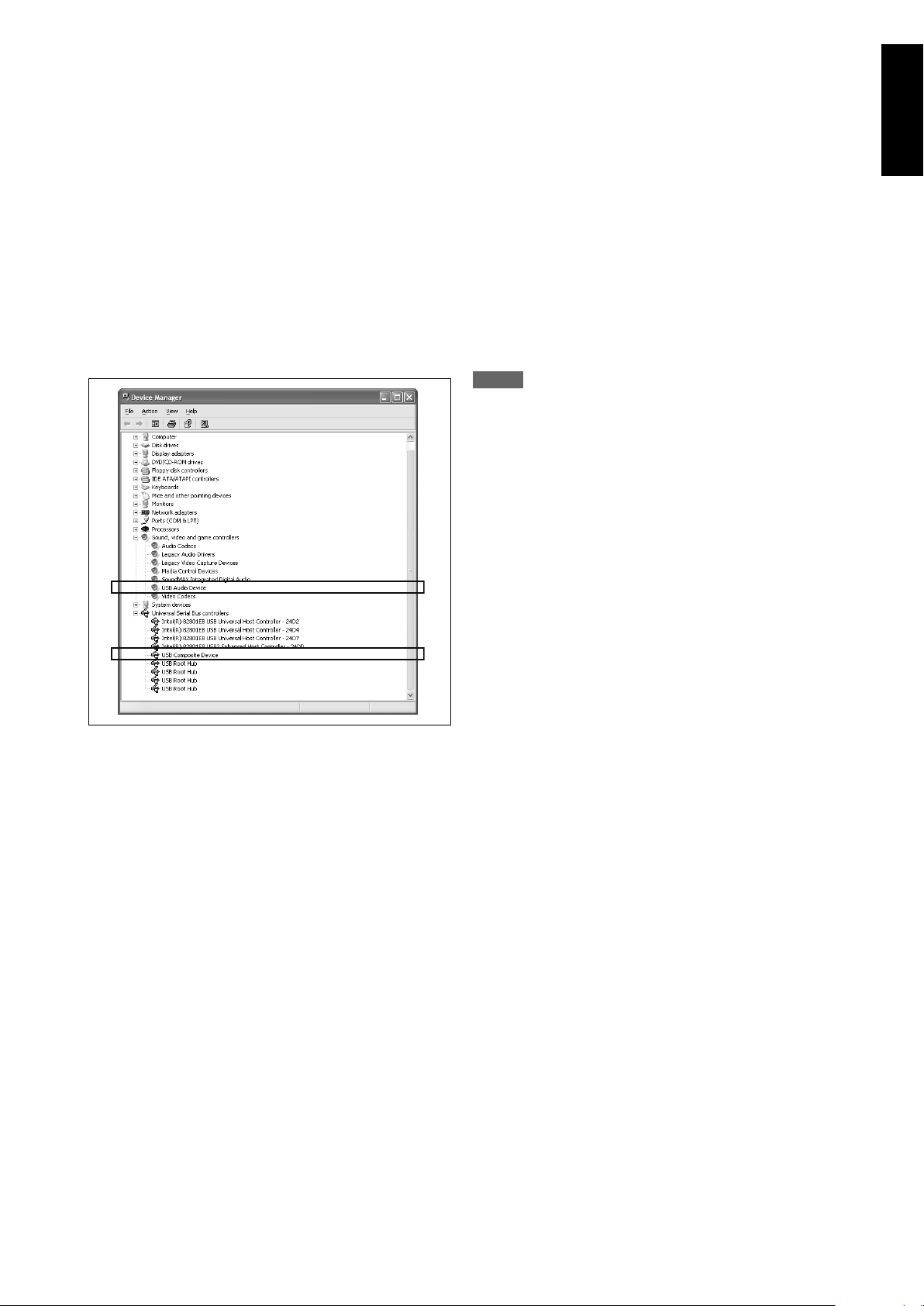
2. Check if the drivers are correctly installed.
1. Open the Control Panel on your PC:
Select [Start] = [Control Panel].
2. Select [System] = [Hardware] = [Device Manager] =
[Sound, video and game controllers] = [Universal Serial
Bus controllers].
• The following window appears, and you can check whether
the drivers are installed.
Now PC is ready for playback through the USB connection.
After installation is completed, you can use your PC as the
playback source. The PC automatically recognizes the receiver
whenever the transmitter is connected to the PC or the USB cable
is connected between the PC and the receiver while the receiver
is turned on.
• When not using the PC as the playback source, disconnect the
transmitter or the USB cable.
To play back sounds on the PC, refer to the manuals supplied
with the sound reproduction application installed in the PC. Start
the application after the USB device is recognized.
If no sound comes from the speakers, check the following
items:
(For both USB WIRELESS and USB TERMINAL)
– check the USB device is recognized properly.
– check the playback software in your PC is compatible with the
USB device.
– open the Control Panel on your PC, select [Sounds and Audio
Devices] = [Audio] tab = [Sound playback] = [Default device],
and check [Default device] is set to [USB Audio device].
(For USB WIRELESS)
– select “USB WIRELESS” as the source.
– connect the USB wireless transmitter correctly with the USB
WIRELESS switch on the receiver “ON.”
–keep proper distance between the receiver and your PC.
– check the ID lamp on the transmitter and the signal indicators
“L” and “R” on the display light up.
(For USB TERMINAL)
– select “USB TERMINAL” as the source.
– connect the USB cable correctly.
NOTES
• DO NOT turn off the receiver or disconnect the transmitter or
the USB cable while installing the drivers and for several
seconds while your PC is recognizing the receiver.
• If your PC does not recognize the receiver, disconnect the
transmitter or the USB cable and connect it again. If it does not
work yet, restart Windows.
• The installed drivers can be recognized only when the
transmitter is connected to your PC or the USB cable is
connected between the receiver and your PC.
• The sound may not be played back correctly—interrupted or
degraded—due to your PC settings and PC specifications.
• In case that the transmitter has an influence on the wireless
systems (based on IEEE 802.11b/11g, the cordless telephone,
and the microwave oven), try measures below:
– press CHANNEL on the transmitter to search for another
frequency. Each time you press CHANNEL, the frequency
advances one channel up from CH 1 up to CH 13.
– press and hold CHANNEL for more than three seconds to
make sure the transmitter detects the best frequency
automatically.
– to keep the distance between the transmitter and the LAN
antenna utilize the supplied extension cord.
• Use a USB cable (version 1.1 or later). Recommended cord
length is 1.5 m.
* Microsoft®, Windows® 98 SE, Windows® Me, Windows® 2000,
and Windows® XP are registered trademarks of Microsoft
corporation.
English
When playing back with USB WIRELESS,
connect the transmitter and aim the transmitter at the antenna. If
any obstacles are in between, playback will be interrupted or the
wireless communication will be canceled.
If noise comes during playback or playback is interrupted
with USB WIRELESS, try measures below:
– press CHANNEL on the transmitter to search for another
frequency. Each time you press CHANNEL, the frequency
advances one channel up from CH 1 up to CH 13.
– press and hold CHANNEL for more than three seconds to make
sure the transmitter detects the best frequency automatically.
13
Page 16
English
123
456
789
10010
1
3
2
L
S.WFR
R
AUTO SURR
TUNED
STEREO
AUTO MUTING
MHz
ANALOG
1
2
3
L
S.WFR
R
AUTO SURR
TUNED
STEREO
AUTO MUTING
MHz
ANALOG
DVR/DVD (DGTL)
VCR (DIGITAL)
DBS (DIGITAL)
TV (DIGITAL)
FM
AM
(Back to the beginning)
USB WIRELESS
USB TERMINAL
DVD MULTI
Basic operations
Source lamps
2
Select the source to play
On the front panel:
Turn SOURCE SELECTOR until the source name
you want appears on the display.
The source lamp corresponding to the selected source lights in
red.
• As you turn SOURCE SELECTOR, the source changes as
follows:
DVD MULTI: Select the DVD player using the analog
discrete output mode (5.1-channel
DVR/DVD (DGTL)*: Select the DVD recorder or DVD player.
VCR (DIGITAL)*: Select the VCR.
DBS (DIGITAL)*: Select the DBS tuner.
TV (DIGITAL)*: Select the TV.
USB WIRELESS: Select the PC component using a
USB TERMINAL: Select the PC component.
FM: Select an FM broadcast.
AM: Select an AM broadcast.
reproduction).
wireless equipment.
1
Turn on the power
Press STANDBY/ON (or AUDIO on the
remote control).
The standby lamp goes off and the source lamp of the current
source lights in red.
To turn off the power (into standby)
Press STANDBY/ON (or AUDIO on the remote control)
again.
The standby lamp lights in red.
NOTE
A small amount of power is consumed in standby mode. To turn
the power off completely, unplug the AC power cord.
14
Current source name appears.
From the remote control:
Press one of the source selecting buttons.
• For USB WIRELESS and USB TERMINAL, press USB. Each
time you press USB, the mode alternates between USB
WIRELESS and USB TERMINAL.
* Selecting the analog or digital input mode
You need to select the proper input mode according to the
connection method (analog or digital) on pages 7 to 11.
• In case of digital connection, you also need to select the correct
digital input terminal. (See “Setting the digital input (DIGITAL IN)
terminals—DIGITAL IN 1/2/3” on page 22.)
From the remote control ONLY:
Press ANALOG/DIGITAL to select the analog or
digital input mode.
• Each time you press the button, the input mode alternates
between the analog input (“ANALOG”) and the digital input
(“DGTL AUTO”). This setting is memorized for each source.
DGTL AUTO (DIGITAL AUTO):
Select for the digital input mode. The
receiver automatically detects the
incoming signal format, then the digital
signal format indicator (LINEAR PCM,
detected signal lights up.
ANALOG: Select for the analog input mode. The
Initial setting: DGTL AUTO
NOTES
• You cannot select the digital input mode when selecting “DVD
MULTI,” “FM,” or “AM” as the source.
• The input mode is fixed to “DGTL AUTO” when selecting “USB
WIRELESS” or “USB TERMINAL” as the source.
ANALOG indicator lights up on the
display.
, , or 96/24) for the
Page 17
3
L
LS RS
S.WFR LFE
CR
AUTO SURR
DIGITAL
DIGITAL
DGTL AUTO DOLBY DIGITAL
DTS
(Back to the beginning)
L
S.WFR
R
AUTO SURR
ANALOG
L
S.WFR
R
AUTO SURR
ANALOG
Adjust the volume
Selecting the digital decode mode
To increase the volume, turn MASTER VOLUME
control clockwise (or press VOLUME + on the
remote control).
To decrease the volume, turn MASTER VOLUME
control counterclockwise (or press VOLUME – on
the remote control).
• When you adjust the volume, the volume level indication
appears on the display for a while.
CAUTION:
Always set the volume to the minimum before starting any
sources. If the volume is set at its high level, the sudden blast of
sound energy can permanently damage your hearing and/or ruin
your speakers.
NOTE
The volume level can be adjusted within the range of “0” (minimum)
to “50” (maximum).
Listening with headphones
You can enjoy not only stereo software but also multi-channel
software through the headphones. (Sounds are down-mixed to the
front channels while playing multi-channel software.)
Connect a pair of headphones to the PHONES jack on the
front panel to activate the HEADPHONE mode.
The HEADPHONE indicator lights up on the display.
• You can also enjoy the Surround/DSP mode through the
headphones—3D HEADPHONE mode. For details, see page
30.
• Disconnecting a pair of headphones from the PHONES jack
cancels the HEADPHONE (or 3D HEADPHONE) mode and
activates the speakers.
CAUTION:
Be sure to turn down the volume:
• Before connecting or putting on headphones, as high volume
can damage both the headphones and your hearing.
• Before removing headphones, as high volume may output from
the speakers.
If the following symptoms occur while playing Dolby Digital or DTS
software with “DGTL AUTO” selected (see page 14), follow the
procedure below:
• Sound does not come out at the beginning of playback.
• Noise comes out while searching for or skipping chapters or
tracks.
From the remote control ONLY:
Press DECODE MODE to select “DOLBY
DIGITAL” or “DTS.”
• Each time you press DECODE MODE, the digital decode mode
changes as follows:
• To play back software encoded with Dolby Digital, select
“DOLBY DIGITAL.”
• To play back software encoded with DTS, select “DTS.”
NOTE
“DOLBY DIGITAL” or “DTS” is automatically reset to “DGTL AUTO”
in the following cases:
- When you turn off the receiver.
- When you select another source.
- When you select “DGTL AUTO” again by pressing ANALOG/
DIGITAL.
The following digital signal format indicators on the display
indicate what type of signal comes into the receiver.
LINEAR PCM: Lights up when Linear PCM signal comes in.
: • Lights up when Dolby Digital signal comes
in.
• Flashes when “DOLBY DIGITAL” is selected
for any software other than Dolby Digital.
: • Lights up when conventional DTS signal
comes in.
• Flashes when “DTS” is selected for any
software other than DTS.
96/24: Lights up when DTS 96/24 signal comes in.
NOTE
When “DGTL AUTO” cannot recognize the incoming signal, no
digital signal format indicator lights up on the display.
English
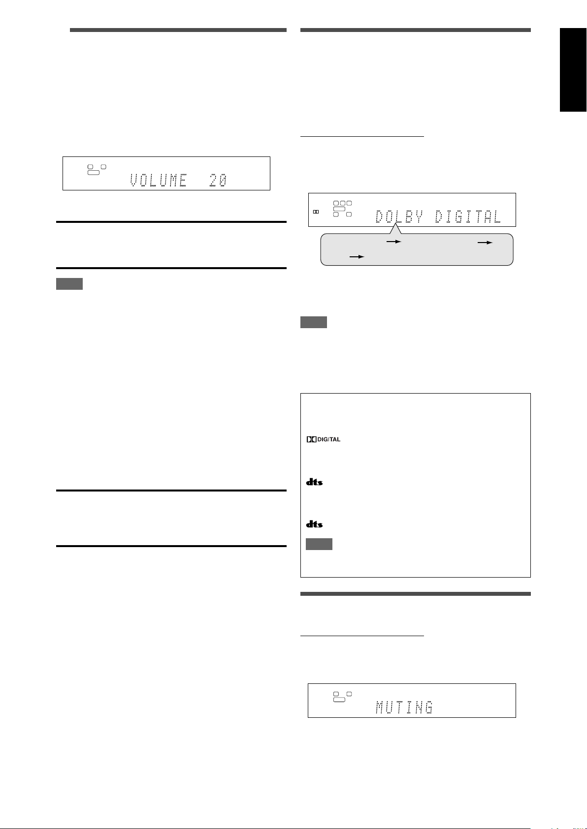
Turning off the sounds temporarily
From the remote control ONLY:
Press MUTING to turn off the sound through all
connected speakers and headphones.
“MUTING” appears on the display and the volume turns off.
To restore the sound, press MUTING again.
• Pressing VOLUME +/– (or turning MASTER VOLUME control
on the front panel) also restores the sound.
15
Page 18
English
S.WFR
LINEAR PCM
L
LSSBRS
S.WFR
PL
NEO : 6
DSP
3D-PHONIC
LFE
C
96 / 24
AUTO SURR
VIRTUAL SB
HEADPHONE
x
DIGITAL
DIGITAL AUTO
ANALOG
DUAL MONO
SBSSB
R
L
LS
SB
RS
S.WFR LFE
C
SBSSB
R
L
LS
SB
RS
S.WFR LFE
C
SBSSB
R
L
S.WFR
R
AUTO SURR
SLEEP
ANALOG
10min
20min
30min 40min
50min
60min
90min
OFF (canceled)
80min
70min
Changing the display brightness
You can dim the display—Dimmer.
From the remote control ONLY:
Press DIMMER repeatedly.
• Each time you press the button, the display brightness changes
as follows:
DIMMER 1: Dims the display.
DIMMER 2: Dims the display more than DIMMER 1.
DIMMER 3: Turns off the display.
(Temporarily canceled when you operate the
receiver.)
DIMMER OFF: Cancels the Dimmer (normal display).
Turning off the power with the Sleep
Timer
You can fall asleep while listening to music—Sleep Timer.
From the remote control ONLY:
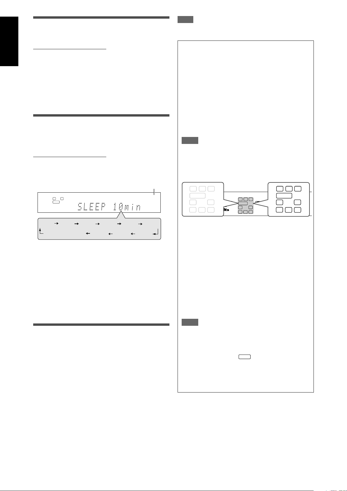
Press SLEEP repeatedly.
• Each time you press the button, the shut-off time changes in 10
minute intervals. The SLEEP indicator lights up on the display.
SLEEP indicator
NOTE
When “DVD MULTI” is selected as the source, this function is not
available.
Basic adjustment of auto memory
This receiver memorizes sound settings for each source:
• when you turn off the power, and
• when you change the source.
When you change the source, the memorized settings for the
newly selected source are automatically recalled.
The following can be stored for each source:
• Analog/digital input mode (see page 14)
• Bass boost (see page 25)
• Digital equalization pattern (see page 24)
• Input attenuator mode (see page 25)
• Midnight mode (see page 21)
• Speaker output level (see page 24)
• Surround/DSP mode selection (see page 33)
NOTE
If the source is FM or AM, you can assign a different setting
for each band.
Signal and speaker indicators on the display
Signal indicators Speaker indicators
When the shut-off time comes:
The receiver turns off automatically.
To check or change the remaining time until the shut-off
time:
Press SLEEP once.
The remaining time (in minutes) until the shut-off time appears.
• To change the shut-off time, press SLEEP repeatedly.
To cancel the Sleep Timer:
Press SLEEP repeatedly so that “SLEEP OFF” appears on the
display. (The SLEEP indicator goes off.)
• The Sleep Timer is also canceled when you turn off the
receiver.
Making sounds natural
JVC’s CC (Compression Compensative) Converter eliminates
jitter and ripples, achieving a drastic reduction in digital distortion
by processing the digital music data in 24 bit-quantization and by
expanding the sampling frequency to 176.4 kHz (for fs 44.1 kHz
signals)/192 kHz (for fs 48 kHz signals) on the front speakers.
By using the CC Converter, you can obtain a natural sound field
from both digital and analog sources.
Press CC CONVERTER repeatedly.
• Each time you press the button, the mode changes as follows:
CC CNVRTR 1: Select when playing back an analog
CC CNVRTR 2: Select when playing back a source with
CC CNVRTR OFF: Select when not using the CC Converter.
16
source or a digital source with non
compressed digital sound signal (Linear
PCM).
The CC CONVERTER 1 indicator lights
up on the display.
compressed digital sound signal (Dolby
Digital or DTS).
The CC CONVERTER 2 indicator lights
up on the display.
The signal indicators light up as follows:
L: • When digital input is selected: Lights up when the
left channel signal comes in.
• When analog input is selected: Always lights up.
R: • When digital input is selected: Lights up when the
right channel signal comes in.
• When analog input is selected: Always lights up.
C: Lights up when the center channel signal comes in.
LS: Lights up when the left surround channel signal comes
in.
RS: Lights up when the right surround channel signal comes
in.
S: Lights up when monaural surround signal comes in.
SB: Lights up when the surround back channel signal
comes in.
LFE: Lights up when the LFE channel signal comes in.
NOTE
When “DVD MULTI” is selected as the source, all the signal
indicators except “SB,” “S,” and “LFE” light up.
The speaker indicators light up as follows:
• The subwoofer indicator (
) lights up when
“SUBWOOFER” is set to “SUBWFR <YES>.” For details,
see page 19.
• The other speaker indicators light up only when the
corresponding speaker is set to “SML (small)” or “LRG
(large),” and also when required for the current playback.
Page 19
Basic settings
L
S.WFR
R
ANALOG
L
S.WFR
R
ANALOG
L
S.WFR
R
ANALOG
L
S.WFR
R
ANALOG
(Back to the beginning)
S
M
L*
1,7
2,4,6
1,3,5
L
S.WFR
R
ANALOG
3.1ch
4.0ch
6.0ch 6.1ch
4.1ch
2.0ch
2.1ch
5.0ch 5.1ch
7.0ch*
7.1ch
3.0ch
(Back to the beginning)
To obtain the best possible sound effect from Surround/DSP
modes (see pages 29 to 33), you need to set up the speaker and
subwoofer information after all the connections are completed.
From pages 17 to 22, how to set speakers and other basic items
of the receiver are explained.
3
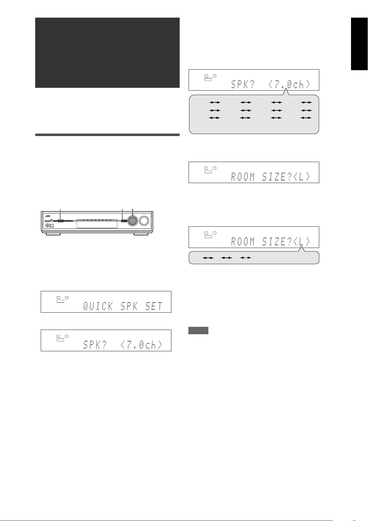
Turn MULTI JOG to select an appropriate
number of the connected speakers (speaker
channel number).
As you turn the jog, the speaker channel number changes as
follows.
• For the details of speaker channel number, see “ Speakers
(channels) number and the size” on page 18.
English
Setting the speaker information
easily—Quick Speaker Setup
Quick Speaker Setup helps you to easily and quickly register the
speaker size, speaker distance, and output level of each speaker
according to your listening room to create the best possible
surround effect.
• You can also register each speaker’s information manually.
For details, see pages 20 and 24.
Before you start, remember...
There is a time limit in doing the following steps. If the setting is
canceled before you finish, start from step 1 again.
1
Press SETTING and turn MULTI JOG until
"QUICK SPK SET" appears on the display.
2
Press SET.
* “7.0ch” is the initial setting.
4
Press SET.
5
Turn MULTI JOG to select an appropriate
room size to match to your listening room.
As you turn the jog, the room size changes as follows.
• To select your appropriate room size, see “Room size and
the speaker distance/output level” on page 18.
* “L” is the initial setting.
6
Press SET.
QUICK SPEAKER SETUP is now completed, then the display
goes back to SETTING menu.
7
Press SETTING.
NOTES
• This procedure will not be completed if you stop in the middle of
the setting process.
• Once Quick Speaker Setup is performed, the speaker output
levels are also set to appropriate values automatically (common
to all sources). If you want to set the speaker output levels
separately for each source, see “Adjusting the speaker output
levels” on page 24.
CONTINUED ON THE NEXT PAGE
17
Page 20
English
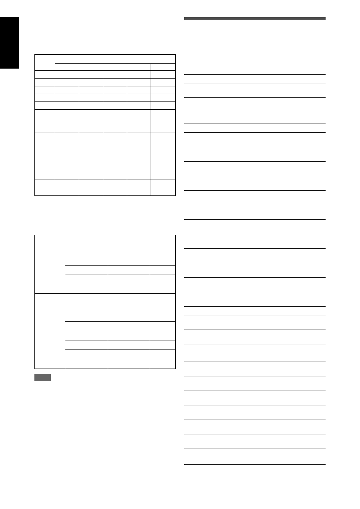
Speakers (channels) number and the size
You can find how each of the speaker size is defined according to
the number of connected speakers (speaker channel “ch” number)
you select.
• Subwoofer is counted as 0.1 channel.
The size of connected speakers
CH L/R C LS/RS SB SUBWFR
2.0CH LARGE NONE NONE NONE NO
2.1CH SMALL NONE NONE NONE YES
3.0CH LARGE SMALL NONE NONE NO
3.1CH SMALL SMALL NONE NONE YES
4.0CH LARGE NONE SMALL NONE NO
4.1CH SMALL NONE SMALL NONE YES
5.0CH LARGE SMALL SMALL NONE NO
5.1CH SMALL SMALL SMALL NONE YES
6.0CH LARGE SMALL SMALL NO
6.1CH SMALL SMALL SMALL YES
7.0CH LARGE SMALL SMALL NO
7.1CH SMALL SMALL SMALL YES
SMALL
(1SPK)
SMALL
(1SPK)
SMALL
(2SPK)
SMALL
(2SPK)
Room size and the speaker distance/output level
According to the selected room size, speaker distance and
speaker output level for each activated speaker is set as follows:
Room size
Speaker Distance
L L/R 3.0 m (10 ft) 0 dB
(Large) C 3.0 m (10 ft) 0 dB
LS/RS 3.0 m (10 ft) 0 dB
SBL(SB)/SBR 3.0 m (10 ft) 0 dB
M L/R 2.7 m (9 ft) 0 dB
(Medium) C 2.4 m (8 ft) –2 dB
LS/RS 2.1 m (7 ft) –3 dB
SBL(SB)/SBR 1.8m (6 ft) –4 dB
S L/R 2.4 m (8 ft) 0 dB
(Small) C 2.1 m (7 ft) –2 dB
LS/RS 1.5 m (5 ft) –4 dB
SBL(SB)/SBR 1.2 m (4 ft) –6 dB
NOTE
Abbreviations used in the tables above stand for the following
speakers and the subwoofer:
- L: Left front speaker
- R: Right front speaker
- C: Center speaker
- LS: Left surround speaker
- RS: Right surround speaker
- SB: Surround back speaker
- SBL: Left surround back speaker
- SBR: Right surround back speaker
- SUBWFR: Subwoofer
Output
level
Basic setting items
You can adjust the following items. See pages in parentheses for
details.
• You cannot select the items which is not available with the
current setting. For example, when the speaker channel number
is set to “
the following items:
S BACK OUT, S BACK DIST, S BACK L DIST, S BACK R DIST
Items To do
QUICK SPK SET Register the number of speakers you connect
SUBWOOFER* Register your subwoofer. (19)
FRONT SPK* Register your front speaker size. (19)
CENTER SPK* Register your center speaker size. (19)
SURROUND SPK* Register your surround speaker size. (19)
S BACK SPK* Register your surround back speaker size.
S BACK OUT* Register the number of your surround back
DIST UNIT Select the measuring unit for the speaker
FRONT L DIST* Register the distance from the left front
FRONT R DIST* Register the distance from the right front
CENTER DIST* Register the distance from the center speaker
SURR L DIST* Register the distance from the left surround
SURR R DIST* Register the distance from the right surround
S BACK DIST* Register the distance from the surround back
S BACK L DIST* Register the distance from the left surround
S BACK R DIST* Register the distance from the right surround
EX/ES/PLIIx Select the EX/ES/PLIIx reproduction mode.
DUAL MONO Select the Dual Mono sound channel. (21)
SUBWOOFER OUT
CROSSOVER Select the cutoff frequency to the subwoofer.
LFE ATT Attenuate the bass (LFE) sounds. (21)
MIDNIGHT MODE
DIGITAL IN 1 Select the component connected to the digital
DIGITAL IN 2 Select the component connected to the digital
DIGITAL IN 3 Select the component connected to the digital
DVD VIDEO IN Select the type of video terminal used for the
VCR VIDEO IN Select the type of video terminal used for the
DBS VIDEO IN Select the type of video terminal used for the
ONE TOUCH OPE
* If you have used Quick Speaker Setup on page 17, these
settings are not required.
<5.1ch>” in Quick Speaker Setup, you cannot select
and the size of your listening room. (17)
(19)
speaker(s). (19)
distance. (20)
speaker to your listening point. (20)
speaker to your listening point. (20)
to your listening point. (20)
speaker to your listening point. (20)
speaker to your listening point. (20)
speaker to your listening point. (20)
back speaker to your listening point. (20)
back speaker to your listening point. (20)
(20)
Select sounds emitted from the subwoofer.
(21)
(21)
Reproduce a powerful sound at night. (21)
coaxial terminal—1(DVR/DVD). (22)
optical terminal—2(DBS). (22)
optical terminal—3(VCR). (22)
DVD recorder or DVD player. (22)
VCR. (22)
DBS tuner. (22)
Memorize the volume level for each source.
(22)
18
Page 21
Operating procedure
S.WFR
L
S.WFR
R
ANALOG
2,4
1,7
3,5
L
S.WFR
R
ANALOG
CENTER SPK
SURROUND SPK
FRONT R DIST
CENTER DIST
(Back to the beginning)
S BACK SPK
SUBWOOFER
FRONT SPK
DIST UNIT
FRONT L DIST
SURR L DIST
S BACK DIST
SURR R DIST
DUAL MONO
CROSSOVER
SUBWOOFER OUT
EX/ES/PLIIx
LFE ATT
MIDNIGHT MODE
DBS VIDEO IN
DVD VIDEO IN
VCR VIDEO IN
DIGITAL IN 1
DIGITAL IN 2
QUICK SPK SET
S BACK OUT
S BACK L DIST
S BACK R DIST
DIGITAL IN 3
ONE TOUCH OPE
L
S.WFR
R
ANALOG
DVR/DVD
DBS
TV
VCR
Setting the speakers
To obtain the best possible surround effect from the Surround and
DSP modes, register the setting about the speaker after all
connections are completed.
• If you have used Quick Speaker Setup on page 17, this setting
is not required.
English
On the front panel ONLY:
Before you start, remember...
There is a time limit in doing the following steps. If the setting is
canceled before you finish, start from step 1 again.
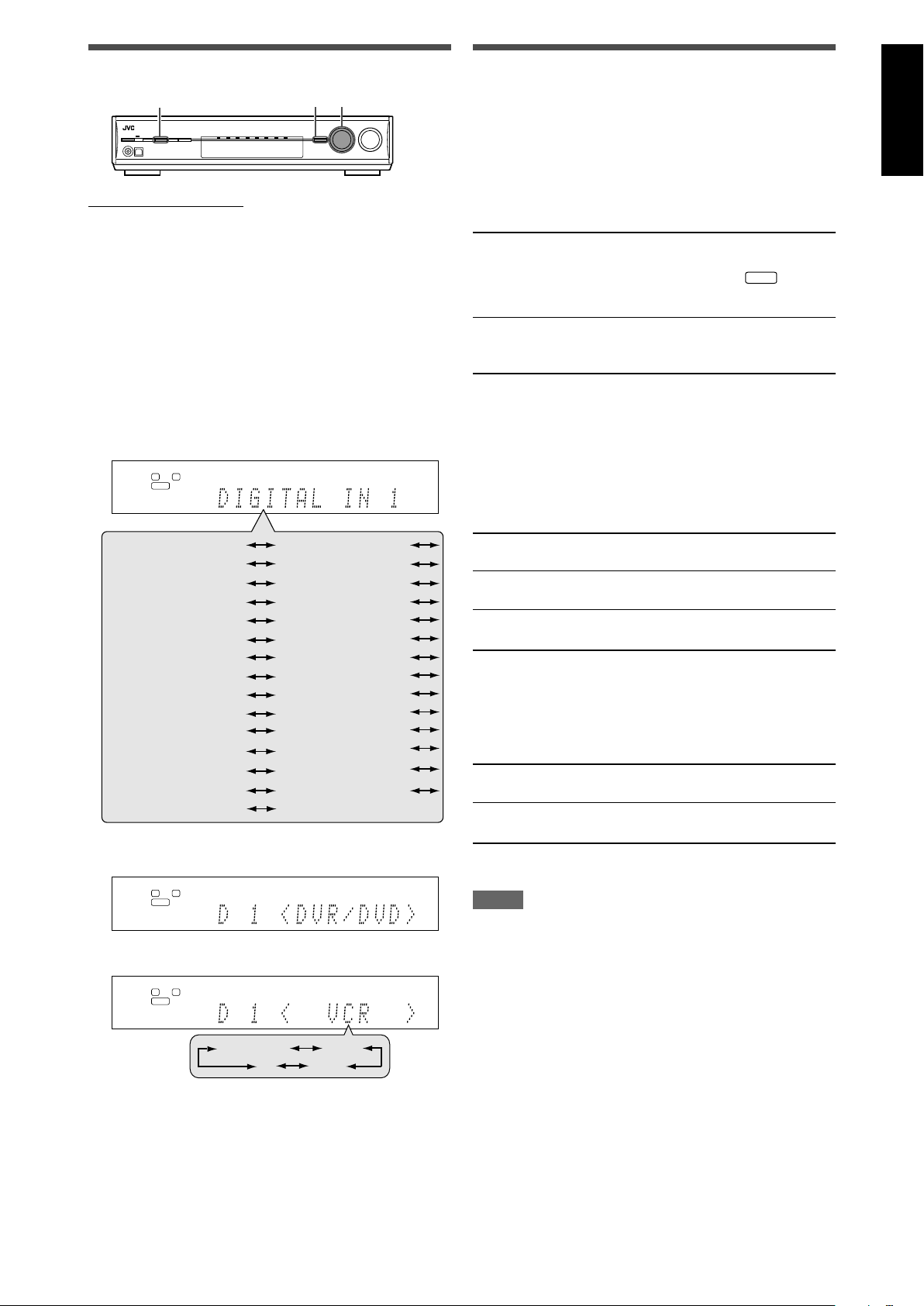
Ex.: When setting DIGITAL IN 1 terminal.
1
Press SETTING.
MULTI JOG now works for the setting operation.
2
Turn MULTI JOG until the item you want to set
appears on the display.
• As you turn MULTI JOG, the setting items change as
follows:
Setting subwoofer information—SUBWOOFER
Select whether you have connected a subwoofer or not.
SUBWFR <YES> Select when you have connected a
subwoofer.
The subwoofer indicator (
on the display. You can adjust the
subwoofer output level (see page 24).
SUBWFR <NO> Select when you have disconnected a
Initial setting: SUBWFER
subwoofer. Selecting this changes the
front speaker size to “LRG” (see below).
<NO>
) lights up
Setting the speaker size—FRONT SPK (front
speakers), CENTER SPK (center speaker),
SURROUND SPK (surround speakers), S BACK SPK
(surround back speakers)
Register the sizes of all the connected speakers.
<LRG> (large) Select when the cone speaker size is larger
than 12 cm.
<SML> (small) Select when the cone speaker size is smaller
than 12 cm.
<NO> Select when you have disconnected a speaker.
(Not selectable for the front speakers.)
3
Press SET.
The current setting of the selected item appears.
4
Turn MULTI JOG to select the appropriate
setting.
Your setting is stored.
5
Press SET.
6
Repeat steps 2 to 5 to set other items if
necessary.
7
Press SETTING.
The source indication resumes on the display.
Initial setting: <LRG> (for the front speakers)
<SML> (for other speakers)
Setting the surround back speaker(s)—S BACK OUT
Register the number of the surround back speaker(s).
SB OUT <1SPK> Select when you use 1 surround back
speaker.
SB OUT <2SPK> Select when you use 2 surround back
speakers.
Initial setting: SB OUT <2SPK>
NOTES
• If you have selected “SML (small)” for the front speaker size,
you cannot select “LRG (large)” for other speakers.
• When “SUBWOOFER” is set to “SUBWFR <NO>,” the front
speaker size is fixed to “LRG” (and you cannot select “SML”).
• When “SURROUND SPK” is set to “SML (small),” you cannot
select “LRG (large)” for the surround back speaker.
• When “SURROUND SPK” is set to “NO,” the surround back
speaker is fixed to “NO.”
• When “S BACK SPK” is set to “NO,” you cannot select “S BACK
OUT.”
• When “SB OUT” is set to “<1SPK>,” connect the surround back
speaker to the left surround back speaker terminal (see page 6).
No sound comes from the surround back speaker if you connect
it to the right surround back speaker terminal.
19
Page 22
English
C
L
R
LS
RS
SBL
SBR
2.1 m
(7 ft)
2.4 m
(8 ft)
2.7 m
(9 ft)
3.0 m
(10 ft)
3.3 m
(11 ft)
Setting the speaker distance
The distance from your listening point to the speakers is one of
the important elements to obtain the best possible sound effect
from the Surround/DSP modes.
By referring to the speaker distance, the receiver automatically
sets the delay time of the sound through each speaker so that
sounds through all the speakers can reach you at the same time.
7 Measuring unit—DIST UNIT
Select which measuring unit you use.
UNIT <meter> Select to set the distance in meters.
UNIT <feet> Select to set the distance in feet.
Initial setting: UNIT <meter>
7 Speaker distance—
FRONT L DIST (for the left front speaker),
FRONT R DIST (for the right front speaker),
CENTER DIST (for the center speaker),
SURR L DIST (for the left surround speaker),
SURR R DIST (for the right surround speaker),
S BACK L DIST (for the left surround back speaker),
S BACK R DIST (for the right surround back speaker)
Adjustable range: 0.3 m to 9.0 m in 0.3 m intervals
(1 ft to 30 ft in 1 ft intervals)
Initial setting: 3.0 m (10 ft) for all speakers
Activating the EX/ES/PLIIx setting—
EX/ES/PLIIx
Depending on this setting, available Surround modes for digital
multi-channel software vary—EX/ES/PLIIx (7.1-channel)
reproduction or 5.1-channel reproduction. Select an appropriate
setting for your enjoyment.
• For details about relation between EX/ES/PLIIx setting and
available Surround mode, see page 32.
• To activate the Surround mode, see page 33.
<AUTO> According to the incoming signal, an appropriate
Surround mode is applied.
• For Dolby Digital Surround EX and DTS-ES
software, 6.1-channel reproduction is applied*.
• For other multi-channel (more than 4 channel)
encoded software, 5.1-channel reproduction is
applied.
<ON> Select to apply 6.1-channel reproduction to both
5.1-channel and 6.1-channel encoded software.
<PLIIx MOVIE>Select to apply PLIIx MOVIE (7.1-channel)
reproduction to both 5.1-channel and 6.1channel encoded software.
<PLIIx MUSIC>Select to apply PLIIx MUSIC (7.1-channel)
reproduction to both 5.1-channel and 6.1channel encoded software.
<OFF> Select to cancel the EX/ES/PLIIx (7.1-channel)
reproduction.
In this case, set the distance as follows:
Left front speaker (L): “FRONT L <3.0m> (10ft)”
Right front speaker (R): “FRONT R <3.0m> (10ft)”
Center speaker (C): “CENTER <3.0m> (10ft)”
Left surround speaker (LS): “SURR L <2.7m> (9ft)”
Right surround speaker (RS): “SURR R <2.7m> (9ft)”
Left surround back speaker (SBL) : “SBACK L <2.4m> (8ft)”
Right surround back speaker (SBR) : “SBACK R <2.4m> (8ft)”
NOTES
• You cannot set the speaker distance for the speakers you have
set to “NO.”
• If you have selected “<1SPK>” for “S BACK OUT” (see page
19), “S BACK DIST” appears instead of “S BACK L DIST” and
“S BACK R DIST.”
Initial setting: <AUTO>
* For some Dolby Digital Surround EX software, Dolby Digital 5.1-
channel reproduction (“DOLBY DIGITAL”) may be applied even
though you have selected “<AUTO>”. In this case, select
“<ON>” to apply “DOLBY D EX.”
From the remote control:
Press EX/ES/PLIIx repeatedly to select either one of the
above.
123
456
789
10010
NOTES
• This function is not available
- when “SURROUND SPK” is set to “NO” (see page 19) or
- when “DVD MULTI” is selected as the source.
• When “S BACK SPK” is set to “NO” (see page 19), the Virtual
Surround Back (see page 32) is applied for EX/ES/PLIIx (6.1channel) reproduction.
20
Page 23
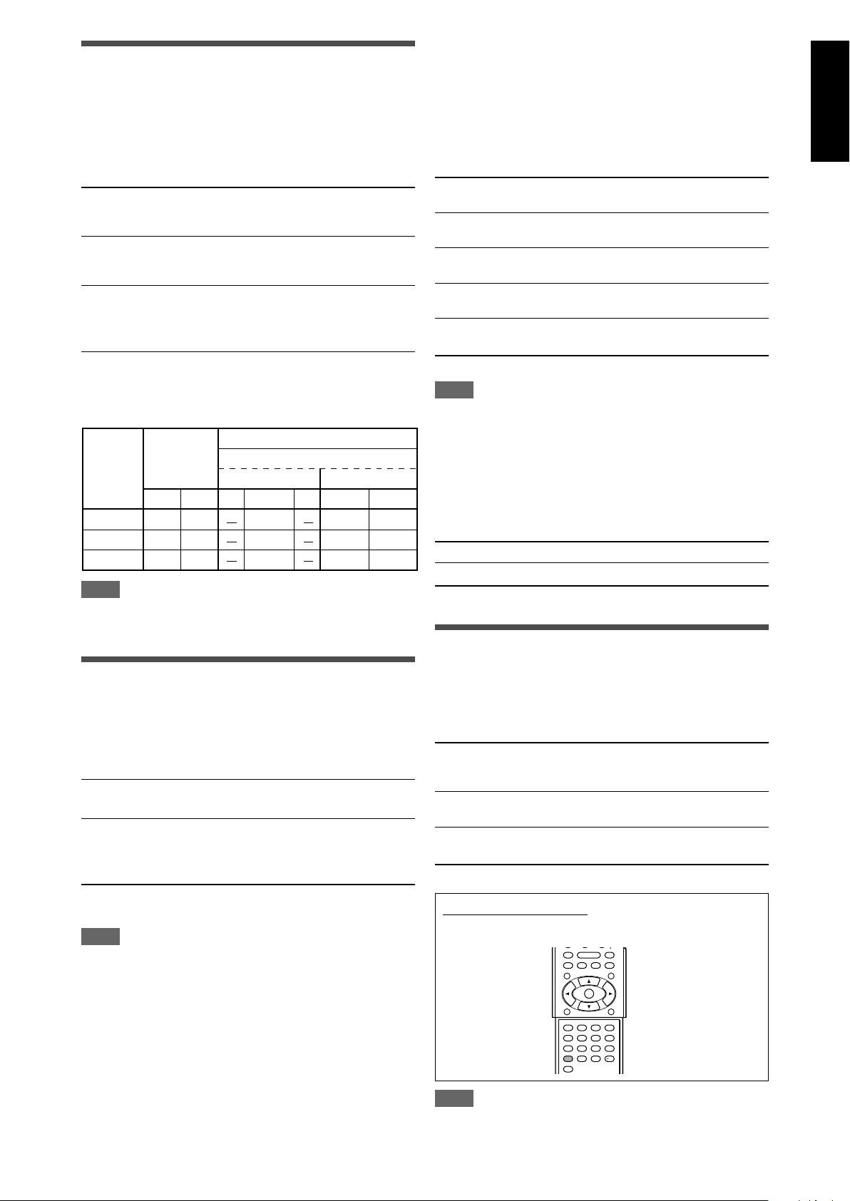
Selecting the main or sub channel
DUAL MONO
setting
Ch 1
Ch 1
Ch 1
Ch 2
Ch 1 Ch 1
SUB Ch 2 Ch 2 Ch 2 Ch 2 Ch 2
Ch1
Ch 1+Ch 2Ch 1+Ch 2Ch 1+Ch 2
LRL RCLR
MAIN
ALL
SURROUND
OFF
With Surround Activated
CENTER SPK setting
SML/LRG NO
—DUAL MONO
You can select the playback sound (channel) you want while
playing digital software recorded (or broadcasted) in Dual Mono
mode (see page 30), which includes two monaural channels
separately. When the receiver detects Dual mono signals, the
DUAL MONO indicator lights up on the display.
D MONO <MAIN>Select to play back the main channel (Ch 1).*
Signal indicator “L” lights up while playing
back this channel.
D MONO <SUB> Select to play back the sub-channel (Ch 2).*
Signal indicator “R” lights up while playing
back this channel.
D MONO <ALL> Select to play back both the main and sub-
channels (Ch 1/Ch 2).*
Signal indicators “L” and “R” light up while
playing back these channels.
Setting the crossover frequency—CROSSOVER
Small speakers cannot reproduce the bass sounds efficiently. If
you use a small speaker in any position, this receiver
automatically reallocates the bass sound elements assigned to
the small speaker to the large speakers.
To use this function properly, set this crossover frequency level
according to the size of the small speaker connected.
• If you have selected “LRG (large)” for all speakers (see page
19), this function will not take effect (“CROSS OFF” appears).
CROSS <80Hz> Select when the cone speaker unit built in the
speaker is about 12 cm.
CROSS <100Hz> Select when the cone speaker unit built in the
speaker is about 10 cm.
CROSS <120Hz> Select when the cone speaker unit built in the
speaker is about 8 cm.
CROSS <150Hz> Select when the cone speaker unit built in the
speaker is about 6 cm.
CROSS <200Hz> Select when the cone speaker unit built in the
speaker is less than 5 cm.
English
Initial setting: D MONO <MAIN>
* Dual Mono signals can be heard from the following speakers—L
(left front speaker), R (right front speaker), and C (center
speaker), with respect to the current Surround setting:
NOTE
The Dual Mono format is not identical with bilingual broadcasting
for TV programs. So this setting does not take effect while
watching such bilingual programs.
Setting bass sound
Setting subwoofer output—SUBWOOFER OUT
The subwoofer emits the LFE signals* and the bass elements of
each speaker set to “SML.”
You can make the bass elements of the front speaker channels
(MAIN) emitted through the subwoofer.
SW <LFE> Select to emit the LFE signals and the bass
SW <LFE+MAIN> Select to emit the bass elements of the front
Initial setting: SW <LFE>
NOTE
• When “SUBWOOFER” is set to “SUBWFR <NO>” (see page
19), this function is not available.
* The LFE signals are emitted only when playing the following
software with the LFE signals:
-Dolby Digital multi channel software
-DTS multi channel software
When playing analog source or linear PCM software, no LFE
signals are emitted.
elements of each speaker set to “SML.”
speakers’ channels (MAIN) when no bass
elements are emitted through the subwoofer
in “SW <LFE>.”
Initial setting: CROSS <100Hz>
NOTE
Crossover frequency is not valid for the HEADPHONE and 3D
HEADPHONE modes.
Setting the low frequency effect attenuator—LFE
ATT
If the bass sound is distorted while playing back software
encoded with Dolby Digital or DTS, set the LFE level to eliminate
distortion.
• This function takes effect only when the LFE signals come in.
LFE <0dB> Normally select this.
LFE <–10dB>Select when the bass sound is distorted.
Initial setting: LFE <0dB>
Using the Midnight mode
—MIDNIGHT MODE
You can enjoy a powerful sound at night using the Midnight mode.
When the Midnight mode is activated, the MIDNIGHT indicator
lights up on the display.
MIDNIGHT <OFF> Select when you want to enjoy surround
with its full dynamic range. (No effect
applied.)
MIDNIGHT <1> Select when you want to reduce the
dynamic range a little.
MIDNIGHT <2> Select when you want to apply the
compression effect fully (useful at night).
Initial setting: MIDNIGHT <OFF>
From the remote control:
Press MIDNIGHT repeatedly to select either one of the
above.
123
456
789
10010
NOTE
When “DVD MULTI” is selected as the source, this function is not
available.
21
Page 24
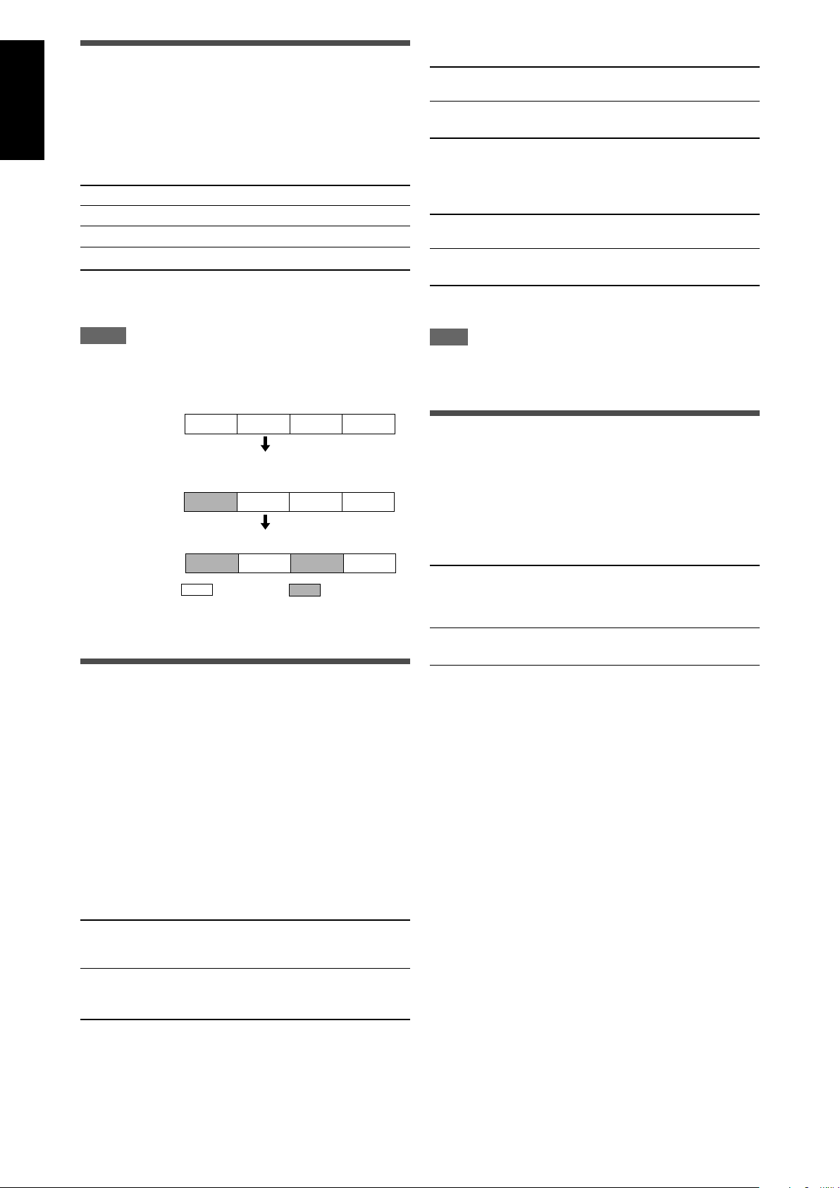
English
DVR/DVD
DIGITAL IN 1 DBS VCR TV
DIGITAL IN 2
DVR/DVD
DBS VCR TV
DIGITAL IN 3
DVR/DVD
DBS VCR TV
Setting the digital input (DIGITAL IN)
terminals—DIGITAL IN 1/2/3
When you use the digital input terminals, register what
components are connected to which terminals—DIGITAL IN 1/2/3
(see page 11) so that the correct source name will appear when
you select the digital source.
Select one of the following components for each terminal:
For the VCR (VCR VIDEO IN):
VCR <S/C> Select when connecting the VCR to the
composite video or S-video input jacks.
VCR <CMPNT> Select when connecting the VCR to the
component video input jacks.
Initial setting: VCR <S/C>
DVR/DVD For the DVD player (or DVD recorder).
DBS For the DBS tuner.
VCR For the VCR.
TV For the TV.
Initial setting: DVR/DVD (for “DIGITAL IN 1”)
DBS (for “DIGITAL IN 2”)
VCR (for “DIGITAL IN 3”)
NOTES
• You cannot assign the same component for different terminals.
The priority order for assignment is as follows:
“DIGITAL IN 1” > “DIGITAL IN 2” > “DIGITAL IN 3.”
Ex.: When “DIGITAL IN 1” is set to “DVR/DVD.”
For “DIGITAL IN 2,” “DBS,” “VCR,” and “TV” are selectable.
• In this case, “VCR” is selected.
For “DIGITAL IN 3,” “DBS” and “TV” are selectable.
: Selectable : Not selectable
• Setting “DIGITAL IN 1” affects “DIGITAL IN 2” and “DIGITAL IN
3” settings. When you have changed “DIGITAL IN 1,” confirm the
components assigned to “DIGITAL IN 2” and “DIGITAL IN 3.”
For the DBS (DBS VIDEO IN):
DBS <S/C> Select when connecting the DBS to the
composite video or S-video input jacks.
DBS <CMPNT> Select when connecting the DBS to the
component video input jacks.
Initial setting: DBS <S/C>
NOTE
You cannot select “CMPNT” for both the VCR and the DBS at
the same time. If you select “CMPNT” for the VCR, the setting
for the DBS is fixed to “S/C” and vice versa.
Memorizing the volume level for each
source—ONE TOUCH OPE
This receiver memorizes some settings separately for each
source. In addition, you can store the volume level for each source
with the other memorized settings (see page 16).
• This receiver memorizes the volume level
– when you turn off the power, and
– when you change the source.
ONETOUCH<ON>
Select to store the volume level separately for each
source. (The ONE TOUCH OPERATION indicator lights
up on the display.)
ONETOUCH<OFF>
Select this not to store the volume level.
Selecting the component video input
mode—DVD VIDEO IN/VCR VIDEO IN/
DBS VIDEO IN
When you use the component video inputs for connecting the
DVD recorder (or DVD player), VCR, or DBS, register the type of
video input jacks.
If you have not selected appropriate video input jacks, you cannot
view the playback picture on the TV or the AV COMPU LINK
remote control system cannot operate properly (see page 34).
When “<S/C>” is selected for each setting, either composite or
S-video signals is converted into component signals (see page
11).
For the DVD recorder or DVD player (DVD VIDEO IN):
DVD <S/C> Select when connecting the DVD recorder
(or DVD player) to the composite video or Svideo input jacks.
DVD <CMPNT> Select when connecting the DVD recorder
(or DVD player) to the component video
input jacks.
Initial setting: DVD <S/C>
Initial setting: ONETOUCH<OFF>
To recall the volume level
With the ONE TOUCH OPERATION indicator lit, the volume level
for the currently selected source is recalled when the source is
selected.
To cancel the One Touch Operation
Set One Touch Operation to “ONETOUCH<OFF>” so that the
ONE TOUCH OPERATION indicator goes off from the display.
22
Page 25
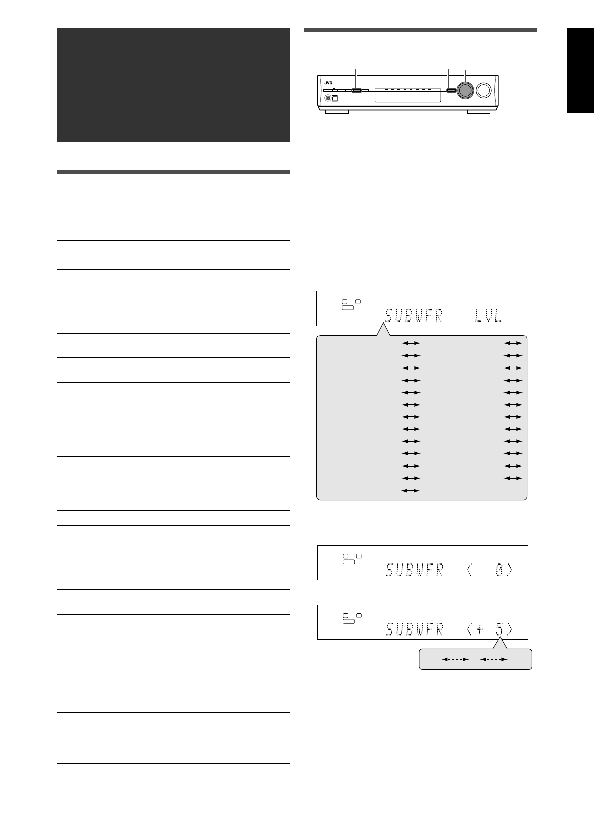
Sound adjustments
L
S.WFR
R
ANALOG
L
S.WFR
R
ANALOG
–10
0 +10
L
S.WFR
R
ANALOG
CENTER LVL
SURR L LVL
D EQ 63Hz
D EQ 250Hz
(Back to the beginning)
SURR R LVL
FRONT L LVL
FRONT R LVL
S BACK L LVL
S BACK R LVL
D EQ 4kHz
BASS BOOST
D EQ 16kHz
LIVENESS
CENTER WIDTH
PANORAMA
ROOM SIZE
DIMENSION
CENTER GAIN CENTER TONE
CENTER ALIGN
SUBWFR LVL
S BACK LVL
INPUT ATT
EFFECT
D EQ 1kHz
2,4
1,7
3,5
Operating procedure
English
On the front panel:
You can make sound adjustment to your preference after
completing basic setting.
Basic adjustment items
You can adjust the following items. See pages in parentheses for
details.
• You cannot select the items which is not available with the
current setting.
Items To do
SUBWFR LVL*
FRONT L LVL*1*2Adjust the left front speaker output level.
FRONT R LVL*1*2Adjust the right front speaker output level.
CENTER LVL*1*2Adjust the center speaker output level. (24)
SURR L LVL*1*
SURR R LVL*1*
S BACK LVL*1*
S BACK L LVL*1*2Adjust the left surround back speaker output
S BACK R LVL*1*2Adjust the right surround back speaker
D EQ 63Hz*
D EQ 250Hz*
D EQ 1kHz*
D EQ 4kHz*
D EQ 16kHz*
BASS BOOST Boost the bass level. (25)
INPUT ATT Attenuate the input level of analog source.
EFFECT*
ROOM SIZE Select the room size for your virtual listening
LIVENESS Select the liveness level for your virtual
PANORAMA Add “wraparound” sound effect with side-
CENTER WIDTH Adjust the center channel localization
DIMENSION Adjust sound localization pattern. (26)
CENTER GAIN Adjust the sound localization of the center
CENTER TONE*1Make the center tone soft or sharp. (26)
CENTER ALIGN Align the vertical localization of the center
*1You can also use the remote control for the adjustment.
*2If you have used Quick Speaker Setup on page 17, these
settings are not required.
1
Adjust the subwoofer output level. (24)
(24)
(24)
2
Adjust the left surround speaker output level.
(24)
2
Adjust the right surround speaker output
level. (24)
2
Adjust the surround back speaker output
level. (24)
level. (24)
output level. (24)
1
1
1
1
Adjust the equalization pattern of each
1
band. (24)
1
(25)
Adjust the effect level. (25)
room. (25)
listening room. (25)
wall image. (25)
between the center speaker and the left/
right speakers. (26)
channel. (26)
channel signals. (26)
Before you start, remember...
There is a time limit in doing the following steps. If the setting is
canceled before you finish, start from step 1 again.
Ex.: When adjusting subwoofer output level.
1
Press ADJUST.
MULTI JOG now works for the sound adjustment.
2
Turn MULTI JOG until the item you want to
adjust appears on the display.
• As you turn MULTI JOG, the adjustment items change as
follows:
3
Press SET.
The current setting for the selected item appears.
4
Turn MULTI JOG to adjust the selected item.
Your adjustment is stored.
5
Press SET.
6
Repeat steps 2 to 5 to adjust other items if
necessary.
7
Press ADJUST.
The source indication resumes on the display.
23
Page 26
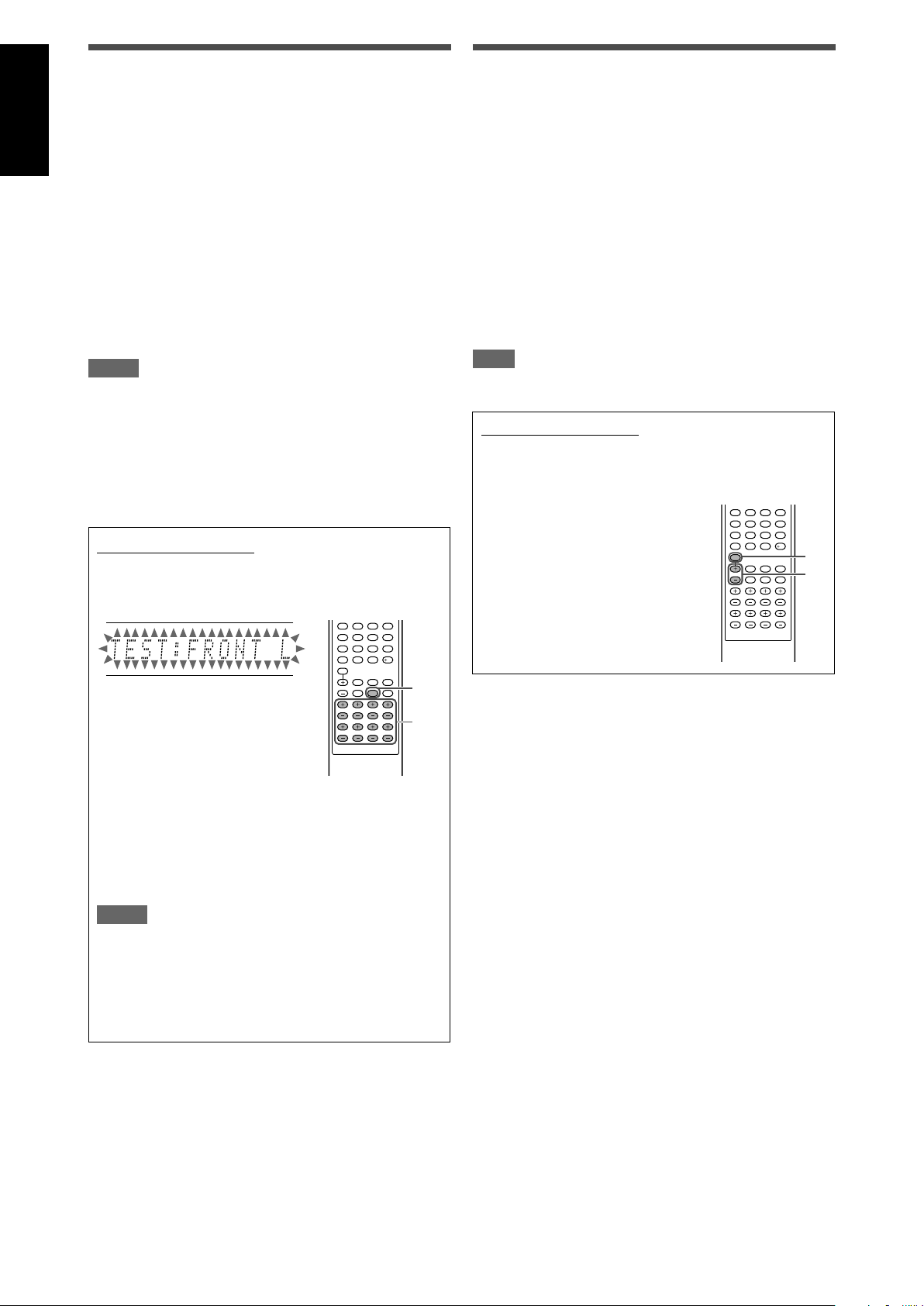
Adjusting the speaker output levels
123
456
789
10010
2
1,3
123
456
789
10010
2
1
Adjusting the equalization patterns—
English
• SUBWFR LVL (subwoofer output level),
• FRONT L LVL (left front speaker output level),
• FRONT R LVL (right front speaker output level),
• CENTER LVL (center speaker output level),
• SURR L LVL (left surround speaker output level),
• SURR R LVL (right surround speaker output level),
• S BACK L LVL (left surround back speaker output level),
• S BACK R LVL (right surround back speaker output level),
You can adjust the speaker output levels.
Adjust all the speakers’ output levels so that you can listen to the
sounds from all the speakers at the same level.
• Once you have made an adjustment, it is memorized for each
source.
Adjustable range: –10 (dB) to +10 (dB) (in 1 step intervals)
Initial setting: 0 (dB) for all speakers
NOTES
• If you have selected “NO” for a speaker (see page 19), the
output level for the corresponding speaker is not adjustable.
• If you have selected “DVD MULTI” as the source, “S BACK LVL,”
“S BACK L LVL,” and “S BACK R LVL” are not adjustable.
• If you have selected “<1SPK>” for “S BACK OUT” (see page
19), “S BACK LVL” appears instead of “S BACK L LVL” and “S
BACK R LVL.”
• While using the headphones, you can adjust only the left and
right front speakers’ output level.
From the remote control:
1
Press TEST to check the speakers’ output balance.
“TEST: FRONT L” starts flashing on the display, and a test
tone comes out of the speakers clockwise.
D EQ 63Hz/250Hz/1kHz/4kHz/16kHz
You can adjust equalization patterns in five frequency bands
(center frequency: 63 Hz, 250 Hz, 1 kHz, 4 kHz, 16 kHz) for the
front speakers.
• Once you have made an adjustment, it is memorized for each
source.
Adjustable range: –8 (dB) to +8 (dB) (in 2 dB intervals)
Initial setting: 0 (dB) for all bands
• When adjustment is made, the DIGITAL EQ indicator lights up
on the display.
If no adjustment is required, set all the frequency bands to
“0 (dB).”
• The DIGITAL EQ indicator goes off from the display.
NOTE
When “DVD MULTI” is selected as the source, this function is not
available.
From the remote control:
Before you start, remember...
There is a time limit in doing the following steps. If the setting is
canceled before you finish, start from step 1 again.
1
Press D. EQ FREQ repeatedly to
select the band you want to adjust.
2
Press D. EQ LEVEL + or – to adjust
the equalization pattern of the
selected band.
3
Repeat steps 1 and 2 to adjust
other bands.
• You can adjust the speaker output levels without the test
tone.
2
Adjust the speaker output levels.
Press the + or – button corresponding to the speaker
you want to adjust.
3
Press TEST again to stop the test tone.
NOTES
• No test tone comes out of the speakers for which the
speaker setting is set to “NO” (see page 19).
• No test tone is available when the headphone is in use or
when “DVD MULTI” is selected as the source.
• If you have selected “<1SPK>” for “S BACK OUT” (see
page 19), press + or – button for L – S. BACK to adjust the
output level.
24
Page 27
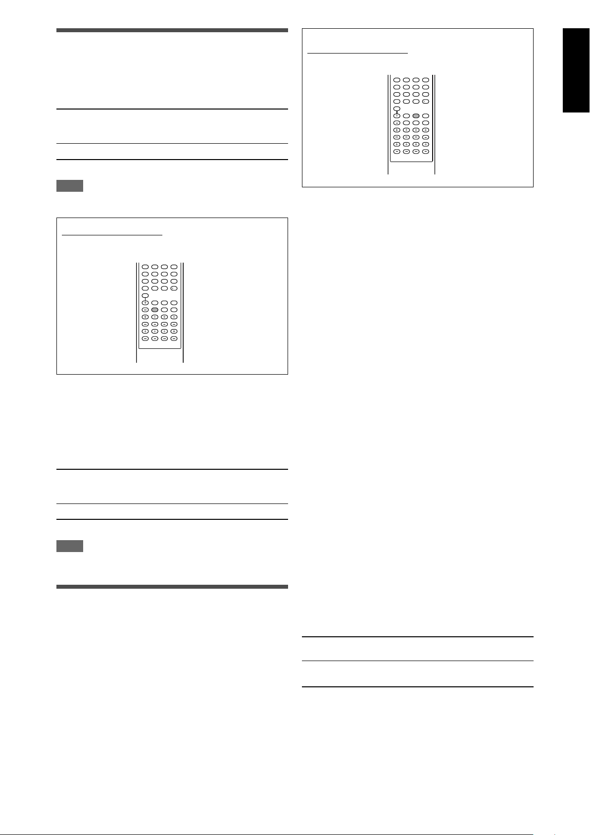
Adjusting the bass sounds
Reinforcing the bass—BASS BOOST
You can boost the bass level—Bass Boost.
• Once you have made an adjustment, it is memorized for each
source.
From the remote control:
Press EFFECT to select the level you want to adjust.
123
456
789
10010
English
B BOOST <ON> Select to boost the bass level.
B BOOST <OFF> Select to deactivate the Bass Boost.
Initial setting: B BOOST <OFF>
NOTE
This function affects only the sound coming out through the front
speakers.
The B.BOOST indicator lights up on the
display.
From the remote control:
Press B.BOOST to select either one of the above.
123
456
789
10010
Attenuating the input signal—INPUT ATT
When the input level of analog source is too high, the sound will
be distorted. If this happens, you need to attenuate the input
signal level to prevent the sound distortion.
• Once you have made an adjustment, it is memorized for each
source.
• You cannot use the remote control for this setting.
ATT <ON> Select to attenuate the input signal level.
ATT <NORMAL> Select to deactivate attenuation.
Initial setting: ATT <NORMAL>
NOTE
When “DVD MULTI” is selected as the source, this function is not
available.
The INPUT ATT indicator lights up on the
display.
Adjusting the sound parameters for
the Surround/DSP modes
You can adjust the Surround/DSP sound parameters to your
preference.
• For details about the Surround/DSP modes, see pages 29 to 33.
Adjusting the effect level for DSP modes—EFFECT
This setting is available only when one of the DSP modes (except
ALL CH STEREO) is in use. To activate DSP mode, see page 33.
• Once you have made an adjustment, it is memorized for each
DSP mode.
Adjustable range: 1 to 5 (in 1 step intervals)
Initial setting: EFFECT <3>
As the number increases, the effect becomes stronger.
Normally, select “3.”
Adjusting the virtual room size for DSP modes—
ROOM SIZE
This setting is available only when one of the DSP modes (except
ALL CH STEREO) is in use. To activate DSP mode, see page 33.
• If “SURROUND SPK” is set to “<NO>” (see page 19), this item
is not adjustable.
• Once you have made an adjustment, it is memorized for each
DSP mode.
• You cannot use the remote control for this setting.
Adjustable range: 1 to 5 (in 1 step intervals)
Initial setting: ROOM SIZE <3>
As the number increases, the interval between reflections
increases so that you will feel as if you were in a larger room.
Normally, select “3.”
Adjusting the liveness effect for DSP modes—
LIVENESS
This setting is available only when one of the DSP modes (except
ALL CH STEREO) is in use. To activate DSP mode, see page 33.
• If “SURROUND SPK” is set to “<NO>” (see page 19), this item
is not adjustable.
• Once you have made an adjustment, it is memorized for each
DSP mode.
• You cannot use the remote control for this setting.
Adjustable range: 1 to 5 (in 1 step intervals)
Initial setting: LIVENESS <3>
As the number increases, the attenuation level of reflections over
time decreases so that acoustics change from “Dead” to “Live.”
Normally, select “3.”
Adjusting the panorama control for Pro Logic IIx
Music and Pro Logic II Music—PANORAMA
This setting is available when Pro Logic IIx Music or Pro Logic II
Music is activated for the analog or digital 2-channel sound signal.
To activate Pro Logic IIx Music or Pro Logic II Music, see page 33.
• Once you have made an adjustment, it is memorized until you
change the setting.
• You cannot use the remote control for this setting.
PANORAMA <ON> Select to add “wraparound” sound effect
with side-wall image.
PANORAMA <OFF> Select to listen to originally recorded
sound.
Initial setting: PANORAMA <OFF>
25
Page 28

English
Adjusting the center channel localization for Pro
Logic IIx Music and Pro Logic II Music—CENTER
WIDTH
This setting is available when Pro Logic IIx Music or Pro Logic II
Music is activated for the analog or digital 2-channel sound signal.
To activate Pro Logic IIx Music or Pro Logic II Music, see page 33.
• If “CENTER SPK” is set to “NO” (see page 19), this item is not
adjustable.
• Once you have made an adjustment, it is memorized until you
change the setting.
• You cannot use the remote control for this setting.
Adjustable range: OFF and 1 to 7 (in 1 step intervals)
Initial setting: C WIDTH
As the number increases, the center channel sound moves
toward the left and right speakers.
Normally, select “3.”
<3>
Adjusting the sound localization position for Pro
Logic IIx Music and Pro Logic II Music—
DIMENSION
This setting is available when Pro Logic IIx Music or Pro Logic II
Music is activated for the analog or digital 2-channel sound signal.
To activate Pro Logic IIx Music or Pro Logic II Music, see page 33.
• Once you have made an adjustment, it is memorized until you
change the setting.
• You cannot use the remote control for this setting.
Adjustable range: 1 to 7 (in 1 step intervals)
Initial setting: DIMENSION <4>
As the number increases, the sound localization moves towards
forward from backward.
Normally, select “4.”
Adjusting the sound localization of the center
channel—CENTER GAIN
This setting is available only when Neo:6 Music is in use.
• If “CENTER SPK” is set to “NO” (see page 19), this item is not
adjustable.
• Once you have made an adjustment, it is memorized until you
change the setting.
• You cannot use the remote control for this setting.
Adjustable range: 0 to 1.0 (in 0.1 step intervals)
Initial setting: C GAIN <0.3>
As the number increases, the center channel will be localized
clearly.
Normally, select “0.3.”
Adjusting the center tone—CENTER TONE
This setting is available when one of the Surround/DSP modes is
in use. To activate Surround/DSP mode, see page 33.
• If “CENTER SPK” is set to “NO” (see page 19), this item is not
adjustable.
• This setting is common to all Surround modes, and is
memorized separately for DSP modes.
Adjustable range: 1 to 5 (in 1 step intervals)
Initial setting: C TONE <3>
As the number increases, the dialogue becomes stronger.
Normally, select “3.”
• When the center tone is set to other than “C TONE <3>,” the
C.TONE indicator lights up on the display.
From the remote control:
Press C. TONE to select the level you want to adjust.
123
456
789
10010
Aligning the vertical localization of the center
channel for Surround/DSP modes—CENTER ALIGN
This setting is available when one of the Surround/DSP modes
(except PLIIx Music, PLII Music, NEO:6 Music, and ALL CH
STEREO) is in use. To activate Surround/DSP mode, see page
33.
• If “CENTER SPK” is set to “NO” (see page 19), this item is not
adjustable.
• Once you have made an adjustment, it is memorized for each
Surround/DSP mode.
• You cannot use the remote control for this setting.
C ALIGN <ON> Select this when you cannot feel as if the
C ALIGN <OFF> Center alignment is turned off.
Initial setting: C ALIGN <OFF>
actors or singers are speaking or singing on
the screen.
26
Page 29

Tuner operations
L
S.WFR
R
TUNED
STEREO
AUTO MUTING
MHz
ANALOG
L
S.WFR
R
TUNED
STEREO
AUTO MUTING
MHz
ANALOG
L
S.WFR
R
TUNED
STEREO
AUTO MUTING
MHz
ANALOG
FM
AM
FM MODE
MEMORY
TUNING/REW
FF/TUNING
1
2
3
4
5
6
7
89
10
0
10
Tuner operations are mainly done from the remote control.
Tuning in to stations manually
From the remote control ONLY:
1
Press FM or AM to select the band.
The last received station of the selected band is tuned in.
2
Press repeatedly or hold TUNING 9 or
( TUNING until the station you want is
tuned in.
• Pressing (or holding) TUNING 9 increases the
frequency.
• Pressing (or holding) ( TUNING decreases the
frequency.
NOTES
• When you hold and release TUNING 9 or ( TUNING, the
frequency keeps changing until a station is tuned in.
• When a station of sufficient signal strength is tuned in, the
TUNED indicator lights up on the display.
• When an FM stereo program is received, the STEREO
indicator also lights up.
English
Using preset tuning
Once a station is assigned a channel number, the station can
be quickly tuned simply by selecting the number. You can
preset up to 30 FM and 15 AM stations.
To store the preset stations
Before you start, remember...
There is a time limit in doing the following steps. If the setting is
canceled before you finish, start from step 2 again.
From the remote control ONLY:
1
Tune in to the station you want to preset
(see “Tuning in to stations manually”
above).
• If you want to store the FM reception mode for this
station, select the FM reception mode you want. See
“Selecting the FM reception mode” on page 28.
2
Press MEMORY.
The channel number position starts flashing on the display
for about 5 seconds.
NOTE
When you have selected “FM” or “AM” by using SOURCE
SELECTOR on the front panel, the remote control may not
work for tuner operations. To use the remote control for tuner
operations, select “FM” or “AM” by using FM or AM button on
the remote control.
CONTINUED ON THE NEXT PAGE
27
Page 30

English
L
S.WFR
R
TUNED
STEREO
AUTO MUTING
MHz
ANALOG
L
S.WFR
R
TUNED
STEREO
AUTO MUTING
MHz
ANALOG
L
S.WFR
R
TUNED
STEREO
AUTO MUTING
MHz
ANALOG
2
1,3
3
Press the numeric buttons (1 – 10, +10) to
select a channel number while the channel
number position is flashing.
• For channel number 5, press 5.
• For channel number 15, press +10, then 5.
• For channel number 30, press +10, +10, then 10.
4
Press MEMORY again while the selected
channel number is flashing on the display.
The selected channel number stops flashing.
The station is assigned to the selected channel number.
5
Repeat steps 1 to 4 until you store all the
stations you want.
To erase a stored preset station
Storing a new station on a used channel number erases the
previously stored one.
To tune in a preset station
From the remote control:
1
Press FM or AM to select the band.
The last received station of the selected band is tuned in and
the numeric buttons now work for tuner operations.
On the front panel:
Before you start, remember...
There is a time limit in doing the following steps. If the setting is
canceled before you finish, start from step 2 again.
1
Turn SOURCE SELECTOR to select “FM” or
“AM.”
The last received station of the selected band is tuned in.
2
Press TUNER PRESET.
“P” appears on the display, and MULTI JOG now works for
selecting preset channels.
3
Turn MULTI JOG to select a preset channel
number.
• To increase the preset channel numbers, turn MULTI JOG
clockwise.
• To decrease the preset channel numbers, turn MULTI JOG
counterclockwise.
Selecting the FM reception mode
When an FM stereo broadcast is hard to receive or noisy, you can
change the FM reception mode while receiving an FM broadcast.
• You can store the FM reception mode for each preset station
(see page 27).
2
Press the numeric buttons (1 – 10, +10) to
select a preset channel number.
• For channel number 5, press 5.
• For channel number 15, press +10, then 5.
• For channel number 30, press +10, +10, then 10.
From the remote control ONLY:
While listening to an FM station, press FM MODE.
• Each time you press the button, the FM reception mode
alternates between “AUTO MUTING” and “MONO.”
AUTO MUTING Normally select this.
When a program is broadcast in stereo,
you will hear stereo sound; when in
monaural, you will hear monaural sound.
This mode is also useful to suppress
static noise between stations. The AUTO
MUTING indicator lights up on the display.
MONO Select this to improve the reception (but
stereo effect will be lost).
In this mode, you will hear noise while
tuning in to the stations. The AUTO
MUTING indicator goes off from the
display. (The STEREO indicator also goes
off.)
Initial setting: AUTO MUTING
28
Page 31

Creating realistic
L
R
LS
RS
SBL
C
SW
SBR
(SB)
sound fields
Reproducing theater ambience
In a movie theater, many speakers are located on the walls to
reproduce impressive multi-channel sound, reaching you from all
directions.
With these many speakers, sound localization and sound
movement can be expressed.
Surround/DSP modes built in this receiver can create almost the
same Surround sound as you can feel in a real movie theater.
Introducing the Surround modes
■ Dolby Digital*
Dolby Digital is a digital signal compression method, developed by
Dolby Laboratories, and enables multi-channel encoding and
decoding.
• When Dolby Digital signal is detected through the digital input,
the indicator lights up on the display.
Dolby Digital 5.1CH
Dolby Digital 5.1CH (DOLBY DIGITAL) encoding method records
and digitally compresses the left front channel, right front channel,
center channel, left surround channel, right surround channel, and
LFE channel signals (total 6 channels, but the LFE channel is
counted as 0.1 channel. Therefore, called 5.1 channel).
Dolby Digital enables stereo surround sounds, and sets the cutoff
frequency of the surround treble at 20 kHz, compared to 7 kHz for
Dolby Pro Logic. As such, the sound movement and “being-there”
feeling are enhanced much more than Dolby Pro Logic.
Dolby Digital EX
Dolby Digital EX (DOLBY D EX) is a digital surround encoding
format that adds the third surround channels, called “surround
back.”
Compared to the conventional Dolby Digital 5.1CH, these newly
added surround back channels can reproduce more detailed
movements behind you while viewing the video software. In
addition, surround sound localization will become more stable.
English
■ Dolby Surround
Dolby Pro Logic II
Dolby Pro Logic II is a multi-channel playback format to convert
2-channel software into 5-channel (plus subwoofer). The matrixbased conversion method used for Dolby Pro Logic II makes no
limitation for the cutoff frequency of the surround treble and
enables stereo surround sound.
• This receiver provides two types of Dolby Pro Logic II modes—
Pro Logic II Movie (PLII MOVIE) and Pro Logic II Music (PLII
MUSIC).
When Dolby Pro Logic II is activated, the indicator lights
up on the display.
PLII MOVIE Suitable for playing any Dolby Surround encoded
software. You can enjoy a sound field very close
to the one created with discrete 5.1-channel
sounds.
PLII MUSIC Suitable for playing any 2-channel stereo
* Manufactured under license from Dolby Laboratories.
“Dolby”, “Pro Logic”, and the double-D symbol are
trademarks of Dolby Laboratories.
software. You can enjoy wide and deep sounds.
CONTINUED ON THE NEXT PAGE
29
Page 32

English
Dolby Pro Logic IIx
Dolby Pro Logic IIx is a newly introduced multi-channel playback
format to convert not only multi-channel software but 2-channel
software into 7.1 channel (or 6.1 channel) that developed from
Dolby Pro Logic II. The matrix-based conversion method used for
Dolby Pro Logic IIx makes no limitation for the cutoff frequency of
the surround treble.
• This receiver provides two types of Dolby Pro Logic IIx modes—
Pro Logic IIx Movie (PLIIx MOVIE) and Pro Logic IIx Music
(PLIIx MUSIC).
When Dolby Pro Logic IIx is activated, “PLIIx MOVIE” or “PLIIx
MUSIC” appear and the
display.
PLIIx MOVIE Suitable for playing any Dolby Surround encoded
software. You can enjoy a sound field with a
natural wraparound effect.
PLIIx MUSIC Suitable for playing any 2-channel stereo
software. You can enjoy wide and deep 7.1channel sounds.
indicator lights up on the
DTS Neo:6
DTS Neo:6 is another conversion method to create 6-channel
(plus subwoofer) from analog/digital 2-channel software by using
the high precision digital matrix decoder used for DTS-ES Matrix
6.1ch.
• This receiver provides the following DTS Neo:6 modes—Neo:6
Cinema (NEO:6 CINEMA) and Neo:6 Music (NEO:6 MUSIC).
When one of them is activated, the NEO:6 indicator lights up on
the display.
NEO:6 CINEMA Suitable for playing movies. You can get the
same atmosphere with 2-channel software as
with 6.1-channel software. It is also effective for
playing software encoded with conventional
surround formats.
NEO:6 MUSIC Suitable for playing music software. The front
channel signals bypass the decoder (resulting in
no loss of sound quality) and the surround
signals transmitted through the other speakers
expand the sound field naturally.
• To enjoy software encoded with Dolby Digital, connect the
source component using the digital terminal on the rear of this
receiver. (See page 11.)
■ DTS**
DTS is another digital signal compression method, developed by
Digital Theater Systems, Inc., and enables multi-channel
encoding and decoding (1ch up to 6.1ch).
• When DTS signal is detected through the digital input, the
indicator lights up on the display.
DTS Digital Surround
DTS Digital Surround (DTS) is another discrete 5.1 channel
digital audio format available on CD, LD, and DVD software.
Compared to Dolby Digital, the DTS Digital Surround format has a
lower audio compression rate which enables it to add breadth and
depth to the sounds reproduced. As such, DTS Digital Surround
features natural, solid, and clear sound.
DTS Extended Surround (DTS-ES)
DTS-ES is another multi-channel digital encoding format.
It greatly improves the 360-degree surround impression and
space expression by adding the third surround channel—surround
back channel.
DTS-ES includes two signal formats with different surround signal
recording methods—DTS-ES Discrete 6.1ch (ES DISCRETE)
and DTS-ES Matrix 6.1ch (ES MATRIX).
DTS-ES Discrete 6.1ch has been designed to encode (and
decode) a 6.1-channel signal discretely to avoid interference with
each channel.
DTS-ES Matrix 6.1ch has been designed to add an extra
surround channel to DTS Digital Surround 5.1-channel. By using a
matrix encoding/decoding method, an additional “surround back”
channel signal is encoded (and decoded) in both the left and right
surround channel signals.
** “DTS”, “DTS-ES”, “Neo:6” and “DTS 96/24” are trademarks
of Digital Theater Systems, Inc.
When using Surround mode, the sounds come out of the
activated speakers which the Surround mode requires.
• If either “SURROUND SPK” or “CENTER SPK” is set to
“<NO>” in the speaker setting (see page 19), the
corresponding channel signals are allocated to and emitted
through the front speakers.
• If both “SURROUND SPK” and “CENTER SPK” are set to
“<NO>” in the speaker setting (see page 19), JVC’s original
3D-PHONIC processing (which has been developed to create
the surround effect through the front speakers only) is used. The
3D-PHONIC indicator lights up on the display.
3D HEADPHONE mode
If you connect a pair of headphones while one of the Surround
modes is in use, the 3D HEADPHONE mode is activated
without respect to the type of software played back.
“3D HEADPHONE” appears on the display and the DSP and
HEADPHONE indicators light up.
About other digital signals
Linear PCM
Uncompressed digital audio data used for DVDs, CDs, and
Video CDs.
DVDs support 2 channels with sampling rates of 48/96 kHz, at
quantization of 16/20/24 bits. On the other hand, CDs and
Video CDs are limited to 2 channels with 44.1 kHz at 16 bits.
• When Linear PCM signal is detected, the LINEAR PCM
indicator lights up.
DTS 96/24
In recent years, there has been increasing interest in higher
sampling rates both for recording and for reproducing at home.
Higher sampling rates allow wider frequency range and greater bit
depths provide extended dynamic range.
DTS 96/24 is a multi-channel digital signal format (fs 96 kHz/24
bits) introduced by Digital Theater Systems, Inc. to deliver “better-
than-CD sound quality” into the home.
• When DTS 96/24 signal is detected, the and 96/24
indicators light up. You can enjoy its 5.1-channel sound with fullquality.
30
Dual Mono
Dual Mono can be easily understood when you think of the
bilingual broadcast for TV programs (however, the Dual Mono
format is not identical with those analog formats).
This format is now adopted in Dolby Digital, DTS, and so on. It
allows two independent channels (called main channel and
sub-channel) to be recorded separately.
• You can select either channel you want to listen to (see
page 21).
Page 33

Introducing the DSP modes
The sound heard in a concert hall, club, etc. consists of direct
sound and indirect sound—early reflections and reflections from
behind. Direct sounds reach the listener directly without any
reflection. On the other hand, indirect sounds are delayed by the
distances of the ceiling and walls. These direct sounds and
indirect sounds are the most important elements of the acoustic
surround effects.
The DSP modes can create these important elements, and give
you a real “being there” feeling.
Reflections from behind
Early reflections
Direct sounds
The DSP modes include the following modes:
• Digital Acoustic Processor (DAP) modes—HALL1, HALL2, LIVE
CLUB, DANCE CLUB, PAVILION, THEATER1, THEATER2
• MONO FILM—Used for all types of 2-channel signals (including
Dual Mono signal)
• All Channel Stereo mode (ALL CH STEREO)
When one of the DSP modes is activated, the DSP indicator lights
up on the display.
When using the DAP mode, the sounds come out of all the
connected and activated speakers.
• If “SURROUND SPK” is set to “
setting (see page 19), JVC’s original 3D-PHONIC processing
(which has been developed to create the surround effect
through the front speakers only) is used.
The 3D-PHONIC indicator lights up on the display.
<NO>” in the speaker
■ MONO FILM
In order to reproduce a more acoustic sound field in your listening
room while viewing monaural sound video software (analog and
2-channel digital signals including Dual Mono signal), you can use
this mode.
The surround effect will be added, and the sound localization of
actor’s words will be improved.
This mode cannot be used for multi-channel digital signals.
When “MONO FILM” is used, sounds come out of all the
connected (and activated) speakers.
• If “SURROUND SPK” is set to “<NO>” in the speaker
setting (see page 19), JVC’s original 3D-PHONIC processing
(which has been developed to create the surround effect
through the front speakers only) is used.
The 3D-PHONIC indicator lights up on the display.
• If incoming signals change from 2-channel digital signal to
another digital signal type, “MONO FILM” is canceled and an
appropriate Surround mode is activated.
■ All Channel Stereo mode (ALL CH STEREO)
This mode can reproduce a larger stereo sound field using all the
connected (and activated) speakers. This mode cannot be used
if “SURROUND SPK” is set to “<NO>” in the speaker setting
(see page 19).
English
■ Digital Acoustic Processor (DAP) modes
You can use the following DAP modes in order to reproduce a
more acoustic sound field in your listening room.
HALL1 Reproduces the spatial feeling of a large
shoebox-shaped hall designed primarily for
classical concerts. (Its seating capacity is about
2000.)
HALL2 Reproduces the spatial feeling of a large
vineyard-shaped hall designed primarily for
classical concerts. (Its seating capacity is about
2000.)
LIVE CLUB Reproduces the spatial feeling of a live music club
with a low ceiling.
DANCE CLUB Reproduces the spatial feeling of a rocking dance
club.
PAVILION Reproduces the spatial feeling of an exhibition
hall with a high ceiling.
THEATER1 Reproduces the spatial feeling of a large theater
where the seating capacity is about 600.
THEATER2 Reproduces the spatial feeling of a small theater
where the seating capacity is about 300.
NOTE
When “THEATER1” or “THEATER2” is activated while playing
back 2-channel analog or digital source, the built-in Dolby Pro
Logic II decoder is activated and the indicator lights up.
Sound reproduced from
normal stereo
Sound reproduced from All
Channel Stereo mode
31
Page 34

English
Using the Surround/DSP modes
Available Surround/DSP modes vary depending on the speaker settings and the incoming signals. See the table below.
• The numbers inside the parentheses following the incoming signal type indicate the number of the front channels and that of the
surround channels. For example, (3/2) indicates that the signals are encoded with three front signals (left/right/center) and two (stereo)
surround signals.
• For EX/ES/PLIIx setting, see page 20.
Incoming Signal Type
EX/ES/PLIIx setting
AUTO ON PLIIx MOVIE PLIIx MUSIC OFF
Dolby Digital Surround EX DOLBY D EX*
3,5
DOLBY D EX*
Dolby Digital (3/2, 2/2) DOLBY DIGITAL DOLBY D EX*
3
3
D+PLIIx MOVIE*
D+PLIIx MOVIE*
2,3
D+PLIIx MUSIC*3DOLBY DIGITAL
2,3
D+PLIIx MUSIC*3DOLBY DIGITAL
Dolby Digital (3/1, 2/1, 3/0, 1/0) DOLBY DIGITAL
Dolby Digital
Dolby Digital (Dual Mono) DUAL MONO
DTS-ES Discrete*
DTS-ES Matrix*
DTS (3/2, 2/2)*
DTS
1
1
1
DTS-ES DSCRT*3DTS-ES DSCRT*3DTS+PLIIx MOVIE*
DTS-ES MATRIX*3DTS-ES MATRIX*3DTS+PLIIx MOVIE*
DTS SURROUND DTS+NEO:6*3DTS+PLIIx MOVIE*
2,3
DTS+PLIIx MUSIC*3DTS SURROUND
2,3
DTS+PLIIx MUSIC*3DTS SURROUND
2,3
DTS+PLIIx MUSIC*3DTS SURROUND
DTS (3/1, 2/1, 3/0, 1/0) DTS
DTS (Dual Mono)
Analog/LINEAR PCM
Dolby Digital (2/0)
PLIIx MOVIE*4/PLIIx MUSIC*4/NEO:6 CINEMA/NEO:6 MUSIC
DUAL MONO
PLII MOVIE/
PLII MUSIC/
NEO:6 CINEMA/
NEO:6 MUSIC
*1DTS 96/24 processing is not applied when the EX/ES/PLIIx setting is activated. If you want to apply the processing, set the EX/ES/
PLIIx setting to “OFF” (see page 20).
2
*
When “S BACK OUT” is set to “<1SPK>,” D+PLIIx MOVIE is changed to DOLBY D EX and DTS+PLIIx MOVIE is changed to
DTS+ EX.
3
*
When “S BACK SPK” is set to “<NO>,” Virtual Surround Back is activated for the modes and the VIRTUAL SB indicator lights up on
the display.
4
*
When “S BACK SPK” is set to “<NO>,” PLllx MOVIE is changed to PLll Movie and PLllx MUSIC is changed to PLll MUSIC.
*5For some Dolby Digital Surround EX software, Dolby Digital 5.1-channel reproduction (“DOLBY DIGITAL”) may be applied even
though you have selected “<AUTO>”. In this case, select “<ON>” to apply “DOLBY D EX.”
About the DSP modes
• The following DSP modes are available regardless of incoming signal type.
HALL1, HALL2, LIVE CLUB, DANCE CLUB, PAVILION, THEATER1, THEATER2
• If an incoming signal is a multi-channel (more than 2 channel) digital signal, “MONO FILM” is not available.
• If “SURROUND SPK” is set to “<NO>,” “ALL CH STEREO” is not available.
Virtual Surround Back
This function creates the great surround effect from the behind as if you have connected the surround back speaker. The VIRTUAL
SB (Surround Back) indicator lights up on the display.
If you have connected (and activated) the surround speakers, you can use Virtual Surround Back without connecting the surround
back speaker.
Virtual Surround Back is activated when EX/ES/PLIIx is set to other than “<OFF>” and when playing back the software including the
following signals:
-Dolby Digital Surround EX
-DTS-ES
-Dolby Digital or DTS with more than 4-channels
32
Page 35

Activating the Surround/DSP modes
1
2
1,3
2
L
LS RS
S.WFR LFE
CR
DIGITAL
DIGITAL AUTO
SURROUND OFF
(Back to the beginning)
Surround modes
*
2
AUTO SURROUND
*
1
HALL1 HALL2 LIVE CLUB DANCE CLUB
PAVILION THEATER1 THEATER2
MONO FILM
*
3
ALL CH STEREO
*
4
L
LS RS
S.WFR LFE
CR
DIGITAL
DIGITAL AUTO
SURROUND OFF
(Back to the beginning)
Surround modes
*
2
AUTO SURROUND
*
1
HALL1 HALL2 LIVE CLUB DANCE CLUB
PAVILION THEATER1 THEATER2
MONO FILM
*
3
ALL CH STEREO
*
4
Available Surround/DSP modes vary depending on the speaker
settings and the incoming signals. For details, see page 32.
Activating one of the Surround/DSP modes automatically
recalls the memorized settings and adjustments.
• To adjust the speaker output level, see page 24.
• When activating one of the Surround/DSP modes, you
can adjust CENTER TONE. (see page 26)
• When activating one of the Surround/DSP modes
(except Pro Logic IIx Music, Pro Logic II Music, NEO:6
Music, and ALL CH STEREO), you can adjust CENTER
ALIGN. (see page 26)
• When activating NEO:6 MUSIC, you can adjust CENTER
GAIN. (see page 26)
• When activating the DSP mode (except All Channel
Stereo mode), you can adjust the following settings:
EFFECT (see page 25)
LIVENESS (see page 25)
ROOM SIZE (see page 25)
• When activating “PLIIx MUSIC” and “PLII MUSIC”, you
can adjust the following settings:
CENTER WIDTH (see page 26)
DIMENSION (see page 26)
PANORAMA (see page 25)
On the front panel:
Before you start, remember...
There is a time limit in doing the following steps. If the setting is
canceled before you finish, start from step 2 again.
1
Select and play any source other than DVD
MULTI.
• Make sure you have selected the input mode (analog or
digital) correctly.
2
Press SURROUND.
MULTI JOG now works for selecting Surround/DSP modes.
3
Turn MULTI JOG to select the Surround/DSP
mode you want.
Ex.: When “DOLBY DIGITAL” is selected for Dolby Digital
multi-channel software:
English
Selecting the Surround/DSP modes
From the remote control:
1
Select and play any source other than DVD
MULTI.
• Make sure you have selected the input mode (analog or
digital) correctly.
2
Press SURROUND repeatedly to select the
Surround/DSP mode you want.
Ex.: When “DOLBY DIGITAL” is selected for Dolby Digital
multi-channel software:
*1“AUTO SURROUND” is the initial setting.
*2Available Surround modes vary depending on the speaker
settings and the incoming signals. For details, see page
32.
*3 If an incoming signal is a multi-channel (more than 2
channel) digital signal, “MONO FILM” is not available.
*4 If “SURROUND SPK” is set to “<NO>,” “ALL CH STEREO”
is not available.
To cancel Surround/DSP modes
Turn MULTI JOG so that “SURROUND OFF” appears on the
display.
When you select “AUTO SURROUND”
You can enjoy the Surround mode easily.
• For details about the Surround modes, see page 32.
• When “AUTO SURROUND” is activated, the AUTO SURR indicator
lights up on the display.
How does “AUTO SURROUND” work?
• If a multi-channel signal comes in, an appropriate Surround
mode will be selected automatically.
• If a Dolby Digital 2-channel signal with surround signal comes
in, “PLIIx MOVIE” or “PLII MOVIE” will be selected.
• If a Dolby Digital 2-channel signal without surround signal
comes in, “SURROUND OFF (stereo)” will be selected.
• If a Linear PCM signal comes in, “SURROUND OFF (stereo)”
will be selected.
*1“AUTO SURROUND” is the initial setting.
*2Available Surround modes vary depending on the speaker
settings and the incoming signals. For details, see page
32.
*3 If an incoming signal is a multi-channel (more than 2
channel) digital signal, “MONO FILM” is not available.
*4 If “SURROUND SPK” is set to “<NO>,” “ALL CH STEREO”
is not available.
To cancel Surround/DSP modes
Press SURROUND repeatedly so that “SURROUND OFF”
appears on the display.
NOTE
“AUTO SURROUND” does not take effect in the following cases:
– While playing an analog source,
– While selecting one of the fixed digital decode mode—“DOLBY
DIGITAL” or “DTS” (see page 15).
33
Page 36

English
AV
COMPU LINK EX
AV
COMPU LINK-III
AV
COMPU LINK
AV
COMPU LINK
AV
COMPU LINK-
III
AV COMPU LINK
remote control
system
The AV COMPU LINK remote control system allows you to
operate JVC’s video components (TV, DVD player*, and VCR)
through this receiver.
This receiver is equipped with the AV COMPU LINK-III, which has
added a function to operate JVC’s video components through the
component video jacks. To use this remote control system, you
need to connect the video components you want to operate,
following the diagrams below and the procedures on page 35.
• Refer also to the manuals supplied with your video components.
* “DVD player” on pages 34 and 35 can be replaced with “DVD
recorder.”
Connections 2: Video cable connection
This receiver is equipped with three types of the video terminals—
composite video, S-video, and component video, and the signals
coming into this receiver through one type of video terminals can
output only through the terminal of the same type. So you need to
connect the video components to this receiver using one of the
following three ways.
• When using the AV COMPU LINK remote control system, set
the video input for the DVD player and the VCR correctly (see
“Selecting the component video input mode—DVD VIDEO IN/
VCR VIDEO IN/DBS VIDEO IN” on page 22); otherwise, the
correct input for this receiver will not be selected on the TV.
Case 1:
When connecting the source equipment to the receiver
through the S-video terminals, connect this receiver to the
TV’s video input 1 terminal using S-video cables.
S-video cable
TV
To video input 1
Source
equipment
S-video cable
RX-D302B
Connections 1: AV COMPU LINK connection
TV
Monaural mini-plugs
(not supplied)
Monaural
mini-plugs
(not supplied)
DVD player
Case 2:
When connecting the source equipment to the receiver
through the composite video jacks, connect this receiver
to the TV’s video input 2 terminal (composite video input)
using composite video cables.
Composite video cable Composite video cable
Source
equipment
Case 3:
When connecting the source equipment to the receiver
through the component video jacks, connect this receiver
to the TV’s video input 2 terminals (component video
input) using component video cables.
Component video cable
Source
equipment
RX-D302B
Component video cable
RX-D302B
TV
To video input 2
(Composite)
TV
To video input 2
(Component)
IMPORTANT:
The AV COMPU LINK remote control system cannot control the
DBS tuner connected to the DBS IN jacks.
NOTES
• When connecting the receiver and a TV with the AV COMPU LINK
EX terminal by using a component video cable, you cannot use
Automatic selection of TV’s input mode (see page 35).
• When connecting only the VCR and DVD player to this receiver,
connect it directly to the receiver using cable with the monaural
mini-plugs.
• You can connect only the TV with AV COMPU LINK EX or AV
COMPU LINK-III terminal to the AV COMPU LINK-III terminal.
VCR
34
Page 37

Connecting procedure
1
If you have already plugged your VCR, DVD
player, TV, and this receiver into the AC
outlets, unplug their AC power cords first.
2
Connect your VCR, DVD player, TV, and this
receiver as follows, using the cables with the
monaural mini-plugs (not supplied).
• See “Connections 1” on the previous page.
3
Connect the audio input/output jacks on the
VCR, DVD player, TV, and this receiver using
the audio cables.
• See pages 7 to 10.
4
Connect the video input/output jacks on the
VCR, DVD player, TV, and this receiver using
the S-video cables, composite video cables,
or component video cables.
• See “Connections 2” on the previous page.
5
Plug the AC power cords of the connected
components and this receiver into the AC
outlets.
6
When turning on the TV for the first time after
the AV COMPU LINK connection, turn the TV
volume to the minimum using the TV volume
control on the TV.
7
Turn on other connected components first,
then turn on this receiver.
• When turning on the VCR, use the remote control supplied
with this receiver (press VCR ).
The AV COMPU LINK remote control system allows you to use
the five basic functions listed below.
Remote control of the TV, DVD player, and VCR using this
remote control
See pages 36 and 37 for details.
• Aim the remote control directly at the remote sensor on each
component.
One-touch DVD play
Simply by starting playback on the DVD player, you can enjoy the
DVD playback without setting other switches manually.
• When the DVD player is connected through the analog input
jacks on this receiver (and analog input is selected), the
receiver automatically turns on and changes the source to
“DVR/DVD” or “DVD MULTI.”
• When the DVD player is connected through the digital input
terminal on this receiver (and digital input is selected), the
receiver automatically turns on and changes the source to
“DVR/DVD DGTL.”
The TV automatically turns on and changes the input mode to the
appropriate position so that you can view the playback picture.
Automatic selection of TV’s input mode
• When you select “TV” (or “TV DIGITAL”) as the source to play on
the receiver, the TV automatically changes the input mode to
the TV tuner so that you can watch TV.
• When you select “DVR/DVD” (or “DVR/DVD DGTL”), “DVD
MULTI,” “VCR” (or “VCR DIGITAL”), or “DBS” (or “DBS DIGITAL”)
as the source to play on the receiver, the TV automatically
changes the input mode to the appropriate position (either video
input 1 or video input 2) so that you can view the playback
picture.
NOTE
This function does not work when you connect this receiver and
the TV with the AV COMPU LINK EX terminal using a component
video cable. In this case, reconnect the TV referring to Case 1 or
Case 2 on page 34.
Automatic power on/off
The TV, DVD player, and VCR turn on and off along with the
receiver.
When you turn on the receiver;
• If the previously selected source is “TV” (or “TV DIGITAL”) or
“DBS” (or “DBS DIGITAL”), only the TV will turn on automatically.
• If the previously selected source is “DVR/DVD” (or “DVR/DVD
DGTL”)or “DVD MULTI,” the TV and DVD player will turn on
automatically.
• If the previously selected source is “VCR” (or “VCR DIGITAL”),
the TV and VCR will turn on automatically.
When you turn off the receiver, the TV, DVD player, and VCR will
turn off.
NOTE
If you turn off the receiver while recording on the VCR, the VCR
will not turn off, but continue recording.
English
One-touch video play
Simply by inserting a video cassette without its safety tab into the
VCR, you can enjoy the video playback without setting other
switches manually. The receiver automatically turns on and
changes the source to “VCR” (or “VCR DIGITAL”).
The TV automatically turns on and changes the input mode to the
appropriate position so that you can view the playback picture.
When you insert a video cassette with its safety tab, press the
play (3) button on the VCR or on the remote control. So, you can
get the same result.
35
Page 38

Operating other
123
456
789
10010
123
456
789
10010
7 VCR
English
JVC products
You can use the supplied remote control to operate not only
this receiver but also other JVC products.
• Refer also to the manuals supplied with the other products.
– Some JVC VCRs can accept two types of the control
signals—remote codes “A” and “B.” This remote control can
operate a VCR whose remote control code is set to “A.”
– Some JVC DVD recorders can accept four types of the control
signals. This remote control can operate a DVD recorder
whose remote control code is set to the initial code. For
details, refer to the manual supplied with the DVD recorder.
• To operate other products, aim the remote control directly at the
remote sensor on the target product.
7 TV
You can always perform the following operation:
VCR : Turn on or off the VCR.
After pressing VCR, you can perform the following operations on
the VCR.
You can always perform the following operations:
TV : Turn on or off the TV.
TV VOL +/–: Adjust the volume on the TV.
TV/VIDEO: Change the input mode (either video
input or TV tuner) on the TV.
After pressing TV, you can perform the following operations on the
TV.
CHANNEL +/–: Change the channel numbers on the
VCR.
1 – 9, 0: Select the channel numbers on the
VCR.
3: Start playback.
7: Stop playback.
8: Pause playback. To release it, press 3.
FF: Fast-wind a tape.
REW: Rewind a tape.
REC PAUSE: Enter recording pause. To star t
recording, press this button then 3.
CHANNEL +/–: Change the channel numbers.
1 – 9, 0, 100+ (+10): Select the channel numbers.
RETURN (10): Switch between the previous channel
and the current channel.
36
Page 39

123
456
789
10010
7 DVD recorder or DVD player
You can always perform the following operation:
To operate the DVD
recorder, set the
mode selector to
“DVR.”
To operate the DVD
player, set the mode
selector to “DVD.”
After setting the mode selector correctly, you can perform the
following operations on the DVD recorder or DVD player.
See the instructions supplied with the DVD recorder or DVD
player for details.
7 Changing the remote control code for DVD
recorder
Some JVC DVD recorders can accept four types of the control
signals. You can assign one of four codes to the remote
control supplied with this receiver for operating your DVD
recorder. For details, refer to the manual supplied with the
DVD recorder.
Initial setting: 03
DVR/DVD : Tu rn on or off the DVD recorder or DVD
player.
After pressing DVR/DVD, you can perform the following operations
on the DVD recorder and DVD player.
3: Start playback.
7: Stop playback.
8: Pause playback. To release it, press 3.
¢: Skip to the beginning of the next
chapter.
4: Return to the beginning of the current
(or previous) chapter.
TOP MENU/MENU: Display the menu recorded on discs.
5/∞/3/2: Select an item on the menu screen.
ENTER: Enter the selected item, channel
number, chapter/title number, or track
number (if required).
Only for DVD recorder operations:
CHANNEL +/–: Change the channel numbers.
1 – 9, 0: Select a channel number (while stopped)
or a chapter/title number, track number
(while playing back). Press ENTER to
enter the number.
REC PAUSE: Enter recording pause. To star t recording,
press 3.
Only for DVD player operations:
1 – 10, 0, +10: Select a chapter/title number, track
number, menu item, etc.
English
1
Set the mode selector to “DVR.”
2
Press and hold DVR/DVD .
3
Press DVR/DVD.
4
Enter the remote control code you want using
buttons 1 – 4, and 0.
EX.: To enter the code “2”, press 0, then 2.
Code for DVR Number to enter
101
202
303
404
5
Release DVR/DVD .
Now, the remote control code has been changed.
If these buttons do not function normally, use the remote
control supplied with your DVD recorder or DVD player.
Refer also to the manuals supplied with the DVD recorder
or DVD player for details.
37
Page 40

Manufacturers’ codes for TV
English
Operating other
manufacturers’
products
By changing the transmittable signals, you can use the
supplied remote control to operate other manufacturers’
products.
• Refer also to the manuals supplied with the other products.
• To operate those components with the remote control, first you
need to set the manufacturers’ codes each for the TV, VCR,
CATV converter, DBS tuner, and DVD player.
• After replacing batteries of the remote control, set the
manufacturers’ codes again.
• All the functions may not be assigned to the buttons in some
equipment.
❏ Changing the transmittable signals for operating
a TV
1
Press and hold TV .
2
Press TV.
3
Enter the manufacturer’s code using buttons
1 – 9, and 0.
See “Manufacturers’ codes for TV” on the right.
4
Release TV .
Now, you can perform the following operations on the TV.
Manufacturer Codes
JVC 01
Akai 02
Bell+Howell 03
Centurion 04
Coronad 05
Daewoo 06, 07, 08
Emerson 09, 10, 11, 12, 13
Fisher 14
GE•Pana 15, 16
GE•RCA 17
Gold Star 18, 19
Hitachi 20, 21
KTV 22, 23
Magnavox 24
Marantz 25
Mitsubishi 25
Panasonic 26, 27
Philips 24
Pioneer 28
Proscan 29
Quasar 30
Radioshack 31
RCA 02, 17, 32, 33, 34, 35
Samsung 36, 37
Sanyo 14
Sears 38
Sharp 39
Sony 40
Symphonic 41, 42
Toshiba 38
Zenith 43, 44
TV : Turn on or off the TV.
TV VOL +/–: Adjust the volume on the TV.
TV/VIDEO: Change the input mode (either TV or
VIDEO).
After pressing TV, you can perform the following operations on
the TV.
CHANNEL +/–: Change the channel numbers.
1 – 9, 0, 100+ (+10): Select the channel numbers.
See the instructions supplied with the TV for details.
5
Try to operate your TV by pressing TV .
When your TV turns on or off, you have entered the correct
code.
If more than one code is listed for your brand of TV, try each
one until the correct one is entered.
Initial setting: 01
Manufacturers’ codes are subject to change without
notice. If they are changed, this remote control cannot
operate the equipment.
38
Page 41

❏ Changing the transmittable signals for operating
a VCR
1
Press and hold VCR .
2
Press VCR.
3
Enter the manufacturer’s code using buttons
1 – 9, and 0.
See “Manufacturers’ codes for VCR” on the right.
4
Release VCR .
Now, you can perform the following operation on the VCR.
VCR : Turn on or off the VCR.
After pressing VCR, you can perform the following operations
on the VCR.
CHANNEL +/–: Change the channel numbers on the
1 – 10, 0, +10: Select the channel numbers on the VCR.
3: Start playback.
7: Stop playback.
8: Pause playback.
FF: Fast-wind a tape.
REW: Rewind a tape.
REC PAUSE: Enter recording pause. To start
See the instructions supplied with the VCR for details.
VCR.
recording, press this button then 3.
Manufacturers’ codes for VCR
Manufacturer Codes
JVC 01, 02, 03, 04
Aiwa 05
Akai 06, 07, 08
Bell+Howell 09
Daewoo 10
Emerson 11, 12, 13, 14, 15
Fisher 16, 17, 18, 19
G.E. 20, 21
Go Video 22
Gold Star 23
Go-Video A 24
Go-Video B 25
Hitachi 20, 26
Magnavox 27, 28, 29
Mitsubishi 30, 31, 32, 33
NEC 34, 35
Panasonic 36, 37
Philips 27
RCA 38
Samsung 39, 40, 41
Sanyo 16, 17, 18, 19
Scott 42
Sharp 43, 44
Shintom 45
Sony 46, 47, 48, 49, 50, 51
Symphonic 52
Teknica 53, 54
Toshiba 55
Zenith 56
English
5
Try to operate your VCR by pressing VCR .
When your VCR turns on or off, you have entered the correct
code.
If more than one code is listed for your brand of VCR, try each
one until the correct one is entered.
Initial setting: 01
Manufacturers’ codes are subject to change without
notice. If they are changed, this remote control cannot
operate the equipment.
39
Page 42

English
❏ Changing the transmittable signals for operating
a CATV converter or DBS tuner
1
Press and hold DBS/CATV .
2
Press DBS.
3
Enter the manufacturer’s code using buttons
1 – 9, and 0.
See “Manufacturers’ codes for CATV converter” or
“Manufacturers’ codes for DBS tuner” below.
4
Release DBS/CATV .
Now, you can perform the following operation on the CATV
converter or DBS tuner.
❏ Changing the transmittable signals for operating
a DVD player
1
Set the mode selector to “DVD.”
2
Press and hold DVR/DVD .
3
Press DVR/DVD.
4
Enter the manufacturer’s code using buttons
1 – 9, and 0.
See “Manufacturers’ codes for DVD player” below.
5
Release DVR/DVD .
Now, you can perform the following operation on the DVD
player.
DBS/CATV : Turn on or off the CATV converter or
DBS tuner.
After pressing DBS, you can perform the following operations
on the CATV converter or DBS tuner.
CHANNEL +/–: Change the channel numbers on the
CATV converter or DBS tuner.
1 – 10, 0: Select the channel numbers on the
CATV converter or DBS tuner.
See the instructions supplied with the CATV converter or DBS
tuner for details.
5
Try to operate your CATV converter or DBS
tuner by pressing DBS/CATV .
When your CATV converter or DBS tuner turns on or off, you
have entered the correct code.
If more than one code is listed for your brand of CATV
converter or DBS tuner, try each one until the correct one is
entered.
Manufacturers’ codes for CATV converter
Manufacturer Codes
G.I. 01
Gemini 02
Hamlin 03, 04, 05, 06
Jerrold 07, 08, 09, 10, 11, 12, 13, 14, 15
Macom 16, 17, 18
Magnavox 19
Oak 20, 21, 22
Panasonic 23, 24
Philips 25, 26, 27, 28, 29, 30
Pioneer 31, 32
S. Atlanta 33, 34, 35
Samsung 36
Tocom 37
Zenith 38, 39
Manufacturers’ codes for DBS tuner
Manufacturer Codes
Echostar 40
G.I. 41
Hitachi 42
Hughes 43
Panasonic 44
Primestar 45
RCA 46
Sony 47
Toshiba 48
Initial setting: 01
DVR/DVD : Turn on or off the DVD player.
3: Start playback.
4: Return to the beginning of the current
chapter (or fast-forward for some
models).
¢: Skip to the beginning of the next chapter
(or fast-reverse for some models).
7: Stop playback.
8: Pause playback.
TOP MENU/MENU:
Display the menu recorded on DVD
VIDEO discs.
5/∞/3/2: Select an item on the menu screen.
ENTER: Enter the selected item.
1 – 9, 0, +10: Select the chapter number.
See the instructions supplied with the DVD player for details.
6
Try to operate your DVD player by pressing
DVR/DVD .
When your DVD player turns on or off, you have entered the
correct code.
Manufacturers’ codes for DVD player
Manufacturer Codes
JVC 01
Hitachi 02
Kenwood 03, 04
Magnavox 05
Marantz 06
Mitsubishi 07
Onkyo 08, 09
Panasonic 10
Philips 06
Pioneer 11
Proscan 12
RCA 12
Samsung 13
Sony 14
Toshiba 05
Yamaha 15
Zenith 05, 16
Initial setting: 01
NOTE
You cannot use this remote control to operate other
manufacturers’ DVD recorder.
Manufacturers’ codes are subject to change without
notice. If they are changed, this remote control cannot
operate the equipment.
40
Page 43

Troubleshooting
English
Use this chart to help you solve daily operational problems. If
there are any problems you cannot solve, contact your JVC’s
service center.
PROBLEM
The power does not come on.
The receiver turns off (enters standby
mode).
Power
“OVER HEAT” flashes on the display,
then the receiver turns off.
No sound from speakers.
Sound
Sound from one speaker only.
Sounds are intermittently distorted by
the outside noise such as a lightning
discharge.
Remote control does not operate as
you intend.
Remote control does not work.
Remote control
Continuous hiss or buzzing during FM
reception.
Tuner
Occasional cracking noise during FM
reception.
POSSIBLE CAUSE
The power cord is not plugged in.
Speakers are overloaded because of high
volume.
Speakers are overloaded because of a
short circuit at the speaker terminals.
The receiver is overloaded because of a
high voltage.
The receiver is overloaded because of high
volume or long time usage.
Speaker signal cables are not connected.
Connections are incorrect.
An incorrect source is selected.
Muting is activated.
An incorrect input mode (analog or digital)
is selected.
Speaker signal cables are not connected
properly.
When you use the digital coaxial connection,
the sounds may be intermittently distorted
by the outside noise such as a lightning
discharge but the sound will be restored
automatically.
The remote control is not ready for your
intended operation.
There is an obstruction hiding the remote
sensor on the receiver.
Batteries are weak.
The mode selector is set to the incorrect
position.
Incoming signal is too weak.
The station is too far away.
The wrong antenna is being used.
Antennas are not connected properly.
Ignition noise from automobiles.
SOLUTION
Plug the power cord into an AC outlet.
1. Stop the playback source.
2. Turn on the receiver again, then turn the
volume down.
Check the speaker wiring. If speaker wiring
is not short-circuited, contact your dealer.
Consult your dealer after unplugging the
power cord.
Turn the volume down or turn off the
receiver for a while and turn it on again.
If the receiver turns off soon after doing
solutions above, consult your dealer after
unplugging the power cord.
Check speaker wiring, then reconnect if
necessary (see page 6) after unplugging
the power cord.
Check the audio connections (see pages 7
to 13) after unplugging the power cord.
Select the correct source.
Press MUTING to cancel the mute (see
page 15).
Select the correct input mode (analog or
digital).
Check speaker wiring and reconnect if
necessary (see page 6) after unplugging
the power cord.
This is not a malfunction.
Set the mode selector correctly, then press
the corresponding source selecting button
before operation.
Remove the obstruction.
Replace batteries.
Set the mode selector to the proper
position.
Connect an outdoor FM antenna or contact
your dealer.
Select another station.
Check with your dealer to be sure you have
the correct antenna.
Check the connections.
Move the antenna farther from automobile
traffic.
41
Page 44

English
Specifications
Designs and specifications are subject to change without
notice.
Amplifier
Output Power
At stereo operation:
Front channels: 110 W per channel, min. RMS, driven
At surround operation:
Front channels: 110 W per channel, min. RMS, driven into
Center channel:
Surround channels: 110 W per channel, min. RMS, driven into
Surround back channels:
into 6 Ω at 40 Hz to 20 kHz with no
more than 0.8% total harmonic
distortion.
6 Ω at 1 kHz with no more than 0.8% total
harmonic distortion.
110 W, min. RMS, driven into 6 Ω at 1 kHz,
with no more than 0.8% total harmonic
distortion.
6 Ω at 1 kHz, with no more than 0.8%
total harmonic distortion.
110 W
per channel
6 Ω at 1 kHz, with no more than 0.8% total
harmonic distortion.
, min. RMS, driven into
Video
Video Input Sensitivity/Impedance:
Composite video: DVR/DVD, VCR, DBS:
S-video: DVR/DVD, VCR, DBS:
Y (luminance): 1 V(p-p)/75 Ω
C (chrominance, burst): 0.286 V(p-p)/75 Ω
Component: DVR/DVD, VCR (DBS):
Y (luminance): 1 V(p-p)/75 Ω
P
B, PR: 0.7 V(p-p)/75 Ω
Video Output Level/Impedance:
Composite video: DVR, VCR, MONITOR OUT:
S-video: DVR, VCR, MONITOR OUT:
Y (luminance): 1 V(p-p)/75 Ω
C (chrominance, burst): 0.286 V(p-p)/75 Ω
Component: MONITOR OUT:
Y (luminance): 1 V(p-p)/75 Ω
PB, PR: 0.7 V(p-p)/75 Ω
Synchronization: Negative
1 V(p-p)/75 Ω
1 V(p-p)/75 Ω
FM tuner (IHF)
Tuning Range: 87.5 MHz to 108.0 MHz
Usable Sensitivity:
Monaural: 12.8 dBf (1.2 µV/75 Ω)
50 dB Quieting Sensitivity:
Monaural: 16.0 dBf (1.7 µV/75 Ω)
Stereo: 37.5 dBf (20.5 µV/75 Ω)
Stereo Separation at REC OUT: 35 dB at 1 kHz
AM tuner
Tuning Range: 530 kHz to 1 710 kHz
Audio
Audio Input Sensitivity/Impedance:
DVR/DVD (DVD MULTI), VCR, DBS, TV:
270 mV/47 kΩ
Audio Input (DIGITAL IN)*:
Coaxial: DIGITAL IN 1(DVR/DVD):
0.5 V(p-p)/75 Ω
Optical: DIGITAL IN 2(DBS), 3(VCR):
–21 dBm to –15 dBm
(660 nm ±30 nm)
USB: USB WIRELESS
USB TERMINAL
* Corresponding to Linear PCM, Dolby Digital, and DTS (with
sampling frequency—32 kHz, 44.1 kHz, 48 kHz).
Audio Output Level:
DVR, VCR: 270 mV
Signal-to-Noise Ratio (’66 IHF/’78 IHF): 80 dB/62 dB
Frequency Response (6 Ω): 20 Hz to 20 kHz (±1 dB)
Bass Boost: +4 dB ±1 dB at 100 Hz
Equalization (at DSP operation):
Center frequency: 63 Hz, 250 Hz, 1 kHz, 4 kHz, 16 kHz
Control range: ±8 dB
General
Power Requirements: AC 120 V , 60 Hz
Power Consumption: 150 W/200 VA (at operation)
0.9 W (in standby mode)
Dimensions (W x H x D): 435 mm x 91.5 mm x 371 mm
Mass: 6.8 kg
USB WIRELESS SYSTEM
The USB wireless transmitter supplied with this receiver supports
Direct Sequence Spreading Spectrum (DSSS) using 2.4 GHz
frequency band.
42
Page 45

Table des matières
Identification des parties ...................................... 2
Pour commencer ................................................... 4
Avant l’installation .................................................................. 4
Vérification des accessoires fournis ...................................... 4
Mise en place des piles dans la télécommande .................... 4
Connexion des antennes FM et AM ...................................... 5
Connexion des enceintes ...................................................... 6
Connexion des appareils vidéo.............................................. 7
Connexion du cordon d’alimentation ................................... 11
Connexion USB ................................................................... 12
Fonctionnement de base .................................... 14
1 Mise de l’appareil sous tension ........................................ 14
2 Sélection de la source de lecture ..................................... 14
3 Ajustement du volume ..................................................... 15
Sélection du mode de décodage numérique ....................... 15
Coupure temporaire du son ................................................. 15
Modification de la luminosité de l’affichage ......................... 16
Mise hors tension de l’appareil avec la minuterie d’arrêt ..... 16
Pour rendre les sons naturels .............................................. 16
Réglages de base ................................................ 17
Réglage facile des informations des enceintes
—Réglage rapide des enceintes ................................... 17
Éléments des réglages de base .......................................... 18
Procédure de fonctionnement.............................................. 19
Réglage des enceintes ........................................................ 19
Mise en service du réglage EX/ES/PLllx—EX/ES/PLllx ...... 20
Sélection du canal principal ou secondaire
—DUAL MONO ............................................................. 21
Réglage des sons graves .................................................... 21
Utilisation du mode de minuit—MIDNIGHT MODE ............. 21
Réglage des prises d’entrée numériques (DIGITAL IN)
—DIGITAL IN 1/2/3 ........................................................ 22
Sélection du mode d’entrée vidéo en composantes
—DVD VIDEO IN/VCR VIDEO IN/DBS VIDEO IN ......... 22
Mémorisation du niveau de volume pour chaque source
—ONE TOUCH OPE ..................................................... 22
Ajustements sonores.......................................... 23
Éléments des réglages de base .......................................... 23
Procédure de fonctionnement.............................................. 23
Ajustement des niveaux de sortie des enceintes ................ 24
Ajustement des courbes d’égalisation
—D EQ 63Hz/250Hz/1kHz/4kHz/16kHz........................ 24
Ajustement des sons graves................................................ 25
Ajustement des paramètres du son pour les modes
Surround/DSP ............................................................... 25
Fonctionnement du tuner ................................... 27
Accord manuel des stations................................................. 27
Utilisation de l’accord par préréglage .................................. 27
Sélection du mode de réception FM .................................... 28
Création de champs sonores réalistes ............. 29
Reproduction de l’ambiance d’un cinéma ............................ 29
Introduction des modes Surround ....................................... 29
Introduction des modes DSP ............................................... 31
Utilisation des modes Surround/DSP .................................. 32
Mise en service des modes Surround/DSP ......................... 33
Système de commande à distance
AV COMPU LINK ............................................. 34
Commande d’autres appareils JVC ................... 36
Commande d’appareils d’autres fabricants ..... 38
Guide de dépannage ........................................... 41
Spécifications ...................................................... 42
Français
1
Page 46

Français
A/V CONTROL RECEIVER
REMOTE CONTROL RM-SRXD301J
TV/VIDEO
AUDIO
TV
DBS/CATV
DVR/DVD
FM
USB
VCR
TV
DBS
DVR/DVD
AM
DVD MULTI
VCR
TV VOL
CHANNEL
VOLUME
REC PAUSE
FM MODE MUTING
MEMORY
TUNING/REW
FF/TUNING
TOP MENU MENU
SURROUND
CC
CONVERTER
ANALOG/DIGITAL
EX/ES/PL x
DECODE MODE
MIDNIGHT
D.EQ FREQ
D.EQ LEVEL
C.TONE DIMMER
B.BOOST
TEST
SLEEP
L – FRONT – R
L – SURR – R
CENTER
SUBWFR
L – S. BACK – R
1
2
3
4
5
6
7
89
10
0
10
RETURN
100
DVR
DVD
EFFECT
7
2
3
i
5
6
o
1
4
8
9
w
e
d
s
a
;
u
r
t
y
p
q
f
g
Identification des
parties
Télécommande
Référez-vous aux pages entre parenthèses pour plus de détails.
1 Touche TV/VIDEO (36, 38)
2 Touches attente/mise sous tension (14, 36 – 40)
AUDIO, TV , DBS/CATV , VCR , DVR/DVD
3 Touches de sélection de source (14, 27, 36 – 40)
TV, DBS, VCR, DVR/DVD, FM, AM, USB, DVD MULTI
4 Touche TV VOL (volume) +/– (36, 38)
5 Touche CHANNEL +/– (36 – 40)
6 • Touches de commande des appareils vidéo (36, 37, 39, 40)
REC PAUSE, REW, FF, 3, 4, 7, 8, ¢
• Touches de commande du tuner (27, 28)
FM MODE, ( TUNING, MEMORY, TUNING 9
7 Touches de fonctionnement pour le enregistreur de DVD ou
l’lecteur de DVD* (37, 40)
TOP MENU, MENU, touches de curseur (3, 2, 5, ∞), ENTER
8 Touche SURROUND (33)
9 Touche EX/ES/PLIIx (20)
p Touche ANALOG/DIGITAL (14)
q Touche DECODE MODE (15)
w Touche MIDNIGHT (21)
e Touches de réglage pour l’égaliseur numérique (24)
D.EQ FREQ, D.EQ LEVEL +/–
r Touche B.BOOST (accentuation des graves) (25)
t Touches de réglage pour le niveau de sortie des enceintes
et du caisson de grave (24)
FRONT L +/–, FRONT R +/–, CENTER +/–, SUBWFR +/–,
SURR L +/–, SURR R +/–, S.BACK L +/–, S.BACK R +/–
y Touche VOLUME +/– (15)
u Sélecteur de mode DVR/DVD (37, 40)
i Touche MUTING (15)
o Touche CC CONVERTER (16)
; • Touches numériques (28, 36 – 40)
1 – 10, 0, +10, 100+
• Touche RETURN (36)
a Touche C. TONE (tonalité centrale) (26)
s Touche EFFECT (25)
d Touche DIMMER (16)
f Touche SLEEP (16)
g Touche TEST (24)
* Ces touches peuvent être utilisées pour commander un
enregistreur de DVD ou un lecteur de DVD JVC avec le
sélecteur de mode réglé sur “DVR” ou “DVD” (voir page 37).
Si ces touches ne fonctionnent pas normalement, utilisez la
télécommande fournie avec votre enregistreur de DVD ou
lecteur de DVD. Référez-vous aussi aux manuels fournis avec
l’enregistreur de DVD ou le lecteur de DVD pour plus de détails.
• Lors de l’utilisation d’un enregistreur de DVD (pour les
appareil JVC UNIQUEMENT), réglez le sélecteur de
mode (u) sur “DVR”.
• Pour commander le lecteur de DVD, réglez le sélecteur
de mode (u) sur “DVD”.
Pour ouvrir le couvercle de
la télécommande, poussez
ici puis faites glisser le
couvercle vers le bas.
2
Page 47

Référez-vous aux pages entre parenthèses pour plus de détails.
DIGITAL EQ
LINEAR PCM
L
LSSBRS
S.WFR
PL
NEO : 6
DSP
3D-PHONIC
LFE
CR
96 / 24
AUTO SURR
C.TONE
VIRTUAL SB
B.BOOST
TUNED
STEREO
SLEEP
AUTO MUTING
INPUT ATT
HEADPHONE
MHz
kHz
x
MIDNIGHT
DIGITAL
DIGITAL AUTO
ANALOG
DUAL MONO
SBSSB
ONE TOUCH OPERATION
CC CONVERTER 1 2
1
2
3
5
87
^
#
$
!
@
=
~
%
4
6
-
0
9
&
*
(
)
AUDIO/VIDEO CONTROL RECEIVER
STANDBY/ON
CC CONVERTER
SETTING ADJUST SURROUND
DVR / DVD VCR DBS TV USB FM
SOURCE
SELECTOR
/ MULTI JOG
MASTER
VOLUME
SET / TUNER PRESET
PHONES USB
AM
DVD MULTI
45 6
q
e
78 9
p
321
w
AV
COMPU LINK-
III
Y
P
B
P
R
COMPONENT VIDEO
VIDEO
AUDIO
MONITOR
OUT
DVR/DVD
IN
TV
IN
DBS
IN
OUT(REC) IN(PLAY)
VCR DVR
OUT(REC)
DVR/DVD
IN(PLAY)
VCR(DBS)
IN
MONITOR
OUT
DVR
OUT(REC)
VCR
OUT(REC) IN(PLAY)
DBS
IN
DVR/DVD
IN(PLAY)
VIDEO
S-VIDEO
L
R
DIGITAL IN
2(DBS)
1(DVR/DVD)
LEFTRIGHT LEFTRIGHT
LEFTRIGHT
ANTENNA
COAXIAL
AM LOOP
FM 75
AM EXT
SUBWOOFER
OUT
3(VCR)
DIGITAL OUT
PCM/STREAM
SURROUND
SPEAKERS
ANTENNA
USB WIRELESS
CAUTION:SPEAKER
IMPEDANCE 6
-
16
SURROUND BACK
SPEAKERS
DVD
MULTI IN
FRONT
CENTER
SUBWOOFER
SURR-L
SURR-R
CENTER
SPEAKER
FRONT
SPEAKERS
q
LEARNING
IDON
123
6
7
89p w
4
5
Panneau avant
1 Touche STANDBY/ON et témoin d’attente (14)
2 Touche CC CONVERTER (16)
3 Touche SETTING (17, 19)
4 Touche ADJUST (23)
5 Touche SURROUND (33)
6 Témoins de source
DVD MULTI, DVR/DVD, VCR, DBS, TV, USB, FM, AM
7 •Touche SET (17, 19, 23)
•Touche TUNER PRESET (28)
Fenêtre d’affichage
1 Indicateur ANALOG (14)
2 Indicateur DUAL MONO (21)
3 Indicateur AUTO SURR (surround) (33)
4 Indicateur HEADPHONE (15, 30)
5 Indicateur CC CONVERTER 1 2 (16)
6 Indicateurs de fonctionnement du tuner (27)
TUNED, STEREO
7 Indicateur DIGITAL EQ (24)
8 Indicateur AUTO MUTING (28)
9 Indicateur C.TONE (26)
0 Indicateur ONE TOUCH OPERATION (22)
- Indicateur INPUT ATT (atténuation) (25)
= Indicateur SLEEP (16)
8 • SOURCE SELECTOR (14, 28)
• MULTI JOG (17, 19, 23, 28, 33)
9 Réglage MASTER VOLUME (15)
p Prise PHONES (15)
q Prise USB (12)
w Fenêtre d’affichage (voir ci-dessous)
e Capteur de télécommande (4)
~ Indicateurs de format du signal numerique (15, 29, 30)
DIGITAL AUTO, LINEAR PCM, , , 96/24
! Indicateurs de signal et d’enceinte (16)
@ Indicateur NEO:6 (30)
# Indicateur VIRTUAL SB (32)
$ Indicateur 3D-PHONIC (30, 31)
% Indicateur DSP (30, 31)
^ Indicateur et (29 – 31)
& Affichage principal
* Indicateur B.BOOST (accentuation des graves) (25)
( Indicateur MIDNIGHT (21)
) Indicateurs d’unité de fréquence
MHz (pour les stations FM), kHz (pour les stations AM)
Français
Panneau arrière
1 Cordon d’alimentation (11)
2 Prises AV COMPU LINK-III (34)
3 Prises DIGITAL IN (11)
• Coaxiale: 1(DVR/DVD)
• Optique: 2(DBS)
• Optique: 3(VCR)
4 Prise DIGITAL OUT (11)
5 Prise USB WIRELESS ANTENNA (12)
6 Prises ANTENNA (5)
7 Prise SUBWOOFER OUT (6)
8 Prises VIDEO (7– 10)
Prises VIDEO (vidéo composite), prises S-VIDEO
• Entrée: DBS IN, VCR IN (PLAY), DVR/DVD IN (PLAY)
• Sortie: VCR OUT (REC), DVR OUT (REC), MONITOR OUT
9 Prises COMPONENT VIDEO (Y, PB, PR) (7– 10)
VCR (DBS) IN, DVR/DVD IN, MONITOR OUT
p Prises AUDIO (7 – 10)
• Entrée: TV IN, DBS IN, VCR IN (PLAY), DVR/DVD IN (PLAY)
• Sortie: VCR OUT (REC), DVR OUT (REC)
q Prises DVD MULTI IN (8)
CENTER, SUBWOOFER, SURR – L, SURR – R
w Prises d’enceinte (6)
SURROUND BACK SPEAKERS, SURROUND SPEAKERS,
CENTER SPEAKER, FRONT SPEAKERS
3
Page 48

Français
123
Pour commencer
Avant l’installation
Précautions générales
• Assurez-vous d’avoir les mains sèches.
• Mettez tous les appareils hors tension.
• Lisez les modes d’emploi fournis avec les appareils qui doivent
être connectés.
Emplacement
• Installez l’ampli-tuner dans un endroit plat et protégé de
l’humidité et de la poussière.
• La température autour de l’ampli-tuner doit être comprise entre
–5˚C et 35˚C.
• Assurez-vous qu’il y a une bonne ventilation autour de
l’appareil. Une mauvaise ventilation peut entraîner une
surchauffe et endommager l’ampli-tuner.
• Laissez suffisamment d’espace entre l’ampli-tuner et le
téléviseur.
Manipulation de l’ampli-tuner
• N’insérez aucun objet métallique à l’intérieur de l’ampli-tuner.
• Ne démontez pas l’ampli-tuner ni ne retirez les vis, les
couvercles ou le compartiment.
• N’exposez pas l’appareil à la pluie ou à l’humidité.
• Ne tirez pas directement sur le cordon d’alimentation. Pour le
débrancher, tenez-le toujours par la fiche de façon à ne pas
endommager le cordon.
• Quand vous êtes en voyage ou absent pendant une période
prolongée, retirez la fiche de la prise secteur murale. Une petite
quantité d’électricité est toujours consommée quand le cordon
d’alimentation est connecté à la prise secteur murale.
Mise en place des piles dans la
télécommande
Avant d’utiliser la télécommande, mettez en place les deux piles
fournies.
1
Faites pression sur le couvercle du
compartiment à piles à l’arrière de la
télécommande et faites le glisser pour le
retirer.
2
Insérez les piles.
Respectez les polarités: (+) à (+) et (–) à (–).
3
Remettez le couvercle en place.
Si la plage de fonctionnement de la télécommande diminue,
remplacez les piles. Utilisez deux piles sèches de type
R6(SUM-3)/AA(15F).
• Les piles fournies ne sont que les pour les réglages initiaux.
Remplacez-les pour continuer d’utiliser l’appareil.
ATTENTION:
Suivez ces précautions pour éviter toute fuite ou fissure des piles:
• Placez les piles dans la télécommande en respectant leurs
polarités: (+) à (+) et (–) à (–).
• Utilisez des piles de type correct. Des piles ayant l’air similaires
peuvent avoir une tension différente.
• Remplacez toujours les deux pile en même temps.
• N’exposez pas les piles à la chaleur ou à une flamme.
Lors de l’utilisation de la télécommande, dirigez celle-ci
directement vers le capteur de télécommande de panneau avant.
Capteur de télécommande
L’ampli-tuner a un ventilateur de refroidissement intégré
qui fonctionne quand l’appareil est sous tension. Assurezvous de laisser un espace suffisant pour la ventilation afin
d’obtenir un effet de refroidissement satisfaisant.
ATTENTION:
Ne connectez pas la fiche d’alimentation secteur à la prise murale
avant que toutes les connexions soient terminées.
Vérification des accessoires fournis
Vérifiez que vous avez bien tous les accessoires fournis suivants.
Si quelque chose manquait, contactez votre revendeur
immédiatement.
• Télécommande (× 1)
• Piles (× 2)
• Antenne cadre AM (× 1)
• Antenne FM (× 1)
• Antenne USB sans fil (× 1)
• Émetteur USB sans fil (numéro de modèle: QAL0708-001) (× 1)
• Câble prolongateur USB (60 cm) (× 1)
4
Page 49

Connexion des antennes FM et AM
ANTENNA
COAXIAL
FM 75
AM EXT
AM LOOP
ANTENNA
Ne connectez pas la fiche d’alimentation secteur à la prise murale avant que toutes les connexions soient
terminées.
Antenne cadre
AM (fournie)
Si la réception FM est mauvaise,
connectez une antenne FM extérieure
(non fourni).
Insérez les languettes
du cadre dans les
fentes de la base pour
assembler l’antenne
cadre AM.
Français
Si la réception AM est
mauvaise, connectez un fil
extérieur recouvert de vinyle
(non fourni).
Connexion de l’antenne AM
Connectez l’antenne cadre AM fourni aux prises AM LOOP.
Connectez le cordon blanc à la prise AM EXT et le cordon noir à
la prise H.
Tournez l’antenne cadre jusqu’à ce que vous obteniez la meilleure
réception possible.
• Si la réception est mauvaise, connectez un fil extérieur
recouvert de vinyle (non fournie) à la prise AM EXT. Laissez
l’antenne cadre AM connectée.
Connexion de l’antenne FM
Connectez provisoirement l’antenne FM fournie à la prise
FM 75 Ω COAXIAL.
Étendez l’antenne FM fournie horizontalement.
• Si la réception est mauvaise, connectez une antenne FM
extérieure (non fournie). Avant de brancher le câble coaxial
75 Ω avec connecteur, déconnectez l’antenne FM fournie.
Antenne FM (fourni)
REMARQUES
• Si l’antenne cadre AM est recouverte de vinyle,
retirez le vinyle en tordant de la façon montrée à
droite.
• Assurez-vous que les conducteurs d’antenne ne
touchent aucunes autres prises, cordons de
connexion et cordon d’alimentation. Cela pourrait
causer une mauvaise réception.
5
Page 50

L
R
LS
RS
SBL
C
SW
SBR
(*SB)
LEFTRIGHT LEFT
RIGHT
LEFTRIGHT
SUBWOOFER
OUT
SURROUND
SPEAKERS
CAUTION:SPEAKER
IMPEDANCE 6
-
16
SURROUND BACK
SPEAKERS
CENTER
SPEAKER
FRONT
SPEAKERS
Connexion des enceintes
1324
12 3
+
–
1
2
+
–
Ne connectez pas la fiche d’alimentation secteur à la prise murale avant que toutes les connexions soient
terminées.
Schéma de disposition des enceintes
Enceinte
Surround arrière
Français
droite (SBR)
*Enceinte
Surround arrière
gauche (SBL)
Enceinte
surround droite
(RS)
ATTENTION:
• Utilisez des enceintes avec l’impédance d’enceinte (SPEAKER
IMPEDANCE) indiquée sur les prises d’enceintes (6 Ω – 16 Ω).
• NE CONNECTEZ PAS plus d’une enceinte à une prise
d’enceinte.
Connexion des enceintes
Mettez tous les appareils hors tension avant d’effectuer les
connexions.
Connexion de l’enceinte centrale et des enceintes avant
1
Tordez et retirez l’isolant à l’extrémité de chaque
cordon d’enceinte.
2
Tournez la prise dans le sens contraire des
aiguilles d’une montre.
3
Insérez le cordon d’enceinte.
• Pour chaque enceinte, connectez les prises (+) et (–) du
panneau arrière aux prises (+) et (–) des enceintes
respectives.
4
Tournez la prise dans le sens des aiguilles d’une
montre.
6
Enceinte
centrale (C)
Caisson de
grave actif
(SW)
Enceinte
surround
gauche (LS)
Enceinte
avant
droite (R)
Enceinte
avant
gauche (L)
Connexion des enceintes Surround et des enceintes Surround
arrière
1
Tordez et retirez l’isolant à l’extrémité de chaque
cordon d’enceinte.
2
Ourver la prise (1), et insérer le cordon d’ enceinte
(2).
•
Pour chaque enceinte, connectez les prises (+) et (–) du
panneau arrière aux prises (+) et (–) des enceintes respectives.
3
Refermer la prise.
*Lors de l’utilisation d’une seule enceinte pour le Surround arrière
Vous pouvez profiter du son Surround avec une seule enceinte
Surround arrière. Lors de l’utilisation d’une seule enceinte
Surround arrière,
– réglez “SB OUT” sur “<1SPK>” (voir page 19)
– connectez l’enceinte Surround arrière à la prise de l’enceinte
Surround arrière gauche. (Aucun son ne sort de l’enceinte
si vous la connectez à la prise de l’enceinte Surround
arrière droite.)
Connexion du caisson de grave actif
En connectant un caisson de grave vous pouvez améliorer les
graves et reproduire les signaux LFE originaux enregistrés dans
la source numérique.
Connectez la prise d’entrée d’un caisson de grave actif à la
prise SUBWOOFER OUT sur le panneau arrière en utilisant
un câble à fiches cinch (non fourni).
• Référez-vous aussi au mode d’emploi fourni avec votre caisson
de grave.
Après avoir connecté toutes les enceintes et/ou un caisson de
grave, réglez correctement l’information de réglage des enceintes
afin d’obtenir le meilleur effet Surround possible. Pour les détails
référez-vous aux pages 17 à 21.
REMARQUE
Vous pouvez placer le caisson de grave à l’endroit que vous
voulez puisque les sons graves ne sont pas directionnels.
Normalement, placez-le devant vous.
Page 51

ı
ΉÏÌ
Ç
Å
DVR
OUT(REC)
DVR/DVD
IN(PLAY)
Y
PB
PR
COMPONENT VIDEO
MONITOR
OUT
DVR/DVD
IN
VCR(DBS)
IN
DVR
OUT(REC)
DVR/DVD
IN(PLAY)
FRONT
Connexion des appareils vidéo
Ne connectez pas la fiche d’alimentation secteur à la prise murale avant que toutes les connexions soient
terminées.
Cet ampli-tuner est muni des prises vidéo suivantes—prises vidéo
composite, S-vidéo et vidéo en composantes.
• Si vos appareils vidéo possèdent des prises S-vidéo
(séparation Y/C) et/ou vidéo en composantes (Y, PB, PR),
connectez-les en utilisant un câble S-vidéo (non fourni) ou un
câble vidéo en composantes (non fourni). En utilisant ces
prises, vous pouvez obtenir une image de meilleure qualité
dans l’ordre suivant:
Composantes > S-vidéo > Composite
IMPORTANT:
Cet ampli-tuner peut convertir les signaux vidéo de la façon suivante:
• Les signaux vidéo composites peuvent être convertis à la fois
en signaux S-vidéo et en signaux en composantes.
• Les signaux S-vidéo peuvent être convertis en signaux en
composantes.
• Les signaux en composantes ne peuvent pas être convertis.
Lors de la conversion de signaux vidéo, vous devez respecter
certains points. Pour les détails, référez-vous à “À propos de la
conversion des signaux vidéo” à la page 11.
7 Connexion d’un enregistreur de DVD ou d’un lecteur de DVD par ses prises de sortie stéréo:
Vert
Bleu
Mettez tous les appareils hors tension avant de
réaliser les connexions.
• Lors de la connexion d’autres appareils, référez-vous aussi à
leur mode d’emploi.
N’UTILISEZ PAS un téléviseur connecté à travers un
magnétoscope ni un téléviseur avec magnétoscope
intégré; sinon, l’image risque d’être déformée.
ATTENTION:
Si vous connecter un dispositif d’amélioration du son tel qu’un
égaliseur graphique entre les appareils source et cet ampli-tuner,
la sortie sonore par cet ampli-tuner peut être déformée.
Si votre appareil vidéo est muni d’une prise AV COMPU LINK
Référez-vous aussi à la page 34 pour des informations détaillées
sur sa connexion et le système de commande à distance AV
COMPU LINK.
Câble vidéo en composantes (non fourni)
Français
Rouge
Enregistreur de
DVD ou lecteur
de DVD
Blanc
Rouge
Câble audio stéréo
Rouge
Câble S-vidéo (non fourni)
Blanc
(non fourni)
Câble vidéo composite
(non fourni)
Câble vidéo composite (non fourni)
REMARQUES
• Choisissez le mode d’entrée analogique. Référez-vous à
“Sélection du mode d’entrée analogique ou numérique” à la
page 14.
• Lors de la connexion d’un enregistreur de DVD ou d’un lecteur
de DVD aux prises d’entrée vidéo en composantes, choisissez
le mode d’entrée vidéo en composantes (DVD VIDEO IN)
correct. Sinon, vous ne pouvez pas voir l’image de lecture sur le
téléviseur ou le système de commande à distance AV COMPU
LINK ne peut pas fonctionner correctement. Voir page 22 pour
les détails.
• Vous pouvez profiter d’un son numérique en utilisant un câble
numérique coaxial ou optique. À l’expédition de l’usine, le mode
d’entrée audio pour un enregistreur de DVD ou un lecteur de
DVD est réglé pour utiliser la prise numérique coaxiale
(DIGITAL IN 1 (DVR/DVD)). Pour en savoir plus sur la connexion
numérique, référez-vous à la page 11.
Å À la sortie vidéo en composantes
• Connectez Y, P
ı À la sortie du canal audio gauche/droit
B et PR correctement.
Ç Uniquement pour l’enregistreur de DVD: À l’entrée
du canal audio gauche/droit
Î À la sortie vidéo composite
‰ À la sortie S-vidéo
Ï Uniquement pour l’enregistreur de DVD: À l’entrée
S-vidéo
Ì Uniquement pour l’enregistreur de DVD: À l’entrée
vidéo composite
7
Page 52

Å
Ï
Ó
ı
Ç
Î
‰
Ì
Ô
DVR
OUT(REC)
DVR/DVD
IN(PLAY)
DVR
OUT(REC)
DVR/DVD
IN(PLAY)
FRONT
COMPONENT VIDEO
MONITOR
OUT
DVR/DVD
IN
VCR(DBS)
IN
DVD
MULTI IN
CENTER
SUBWOOFER
SURR-L
SURR-R
È
Y
P
B
P
R
7 Connexion d’un enregistreur de DVD ou d’un lecteur de DVD par ses prises de sortie analogiques discrètes
(DVD MULTI IN):
Cette connexion est la meilleure méthode de connexion pour profiter du son des DVD Audio. Quand un disque DVD Audio est reproduit,
le son original de grande qualité peut être reproduit uniquement avec cette connexion.
Mettez tous les appareils hors tension avant de réaliser les connexions.
• Lors de la connexion d’autres appareils, référez-vous aussi à leur mode d’emploi.
Vert
Bleu
Câble vidéo en composantes (non fourni)
Français
Rouge
Câble S-vidéo (non fourni)
Câble audio monophonique (non fourni)
Blanc
Rouge
Rouge
Blanc
Câble audio monophonique (non fourni)
Câble audio stéréo
(non fourni)
Câble audio stéréo
(non fourni)
Câble vidéo composite
(non fourni)
Enregistreur de
DVD ou lecteur
de DVD
Câble vidéo composite (non fourni)
REMARQUE
Lors de la connexion d’un enregistreur de DVD ou d’un lecteur de
DVD aux prises d’entrée vidéo en composantes, choisissez le
mode d’entrée vidéo en composantes (DVD VIDEO IN) correct.
Sinon, vous ne pouvez pas voir l’image de lecture sur le
téléviseur ou le système de commande à distance AV COMPU
LINK ne peut pas fonctionner correctement. Voir page 22 pour les
détails.
Å À la sortie audio du canal surround gauche/droit
ı À la sortie audio du canal central
Ç À la sortie vidéo en composantes
• Connectez Y, P
B et PR correctement.
Î À la sortie du caisson de grave
‰ À la sortie audio du canal avant gauche/droit
Ï Uniquement pour l’enregistreur de DVD: À l’entrée
audio du canal avant gauche/droit
Ì À la sortie vidéo composite
Ó À la sortie S-vidéo
È Uniquement pour l’enregistreur de DVD: À l’entrée
S-vidéo
Ô Uniquement pour l’enregistreur de DVD: À l’entrée
vidéo composite
À propos de “DVD MULTI”
Quand vous choisissez “DVD MULTI” comme source (voir page 14), vous pouvez profiter du son de sortie analogique discret
(reproduction à 5,1 canaux) à partir de l’appareil connecté.
• Vous aurez peut-être besoin de choisir le mode de sortie analogique distincte sur l’appareil.
REMARQUES
• Lors de l’utilisation d’un casque d’écoute, vous pouvez écouter uniquement le son des canaux avant (gauche et droit). Le mode
3D HEADPHONE (voir page 30) n’est pas disponible.
• Les modes Surround/DSP (voir pages 29 à 33) ne sont pas disponibles pour “DVD MULTI”.
8
Page 53

VCR
OUT(REC) IN(PLAY)
AUDIO
OUT(REC) IN(PLAY)
VCR
Å
ı
ΉÏÌÇ
Y
P
B
P
R
COMPONENT VIDEO
MONITOR
OUT
DVR/DVD
IN
VCR(DBS)
IN
Å
Ne connectez pas la fiche d’alimentation secteur à la prise murale avant que toutes les connexions soient
terminées.
7 Connexion d’un magnétoscope
Mettez tous les appareils hors tension avant de réaliser les connexions.
• Lors de la connexion d’autres appareils, référez-vous aussi à leur mode d’emploi.
Vert
Bleu
Câble vidéo en composantes (non fourni)
Rouge
Magnétoscope
Blanc
Rouge
Français
Rouge
Blanc
Câble S-vidéo (non fourni)
Câble vidéo composite (non fourni)
REMARQUES
• Choisissez le mode d’entrée analogique. Référez-vous à
“Sélection du mode d’entrée analogique ou numérique” à la
page 14.
• Lors de la connexion d’un magnétoscope aux prises d’entrée
vidéo en composantes, choisissez le mode d’entrée vidéo en
composantes (VCR VIDEO IN) correct. Sinon, vous ne pouvez
pas voir l’image de lecture sur le téléviseur ou le système de
commande à distance AV COMPU LINK ne peut pas
fonctionner correctement. Voir page 22 pour les détails.
• Vous pouvez profiter d’un son numérique en utilisant un câble
numérique coaxial ou optique. À l’expédition de l’usine, le mode
d’entrée audio pour le magnétoscope est réglé sur l’utilisation
de la prise optique numérique (DIGITAL IN 3 (VCR)). Pour en
savoir plus sur la connexion numérique, référez-vous à la page
11.
Câble audio stéréo
(non fourni)
Câble vidéo
composite (non fourni)
Å À la sortie vidéo en composantes
• Connectez Y, P
B et PR correctement.
ı À la sortie du canal audio gauche/droit
Ç À l’entrée du canal audio gauche/droit
Î À la sortie vidéo composite
‰ À la sortie S-vidéo
Ï À l’entrée S-vidéo
Ì À l’entrée vidéo composite
9
Page 54

Français
Å
ı
Î
Ç
Y
P
B
P
R
COMPONENT VIDEO
MONITOR
OUT
DVR/DVD
IN
VCR(DBS)
IN
B
N
/
COMPONENT VIDEO
MONITOR
OUT
DVR/DVD
IN
VCR(DBS)
IN
Y
P
B
P
R
U
Å
ı
ÎÇ
Ne connectez pas la fiche d’alimentation secteur à la prise murale avant que toutes les connexions soient terminées.
7 Connexion d’un tuner DBS
Mettez tous les appareils hors tension avant de réaliser les connexions.
• Lors de la connexion d’autres appareils, référez-vous aussi à leur mode d’emploi.
Câble vidéo en composantes (non fourni)
Vert
Bleu
Rouge
DBS
IN O
Blanc
Rouge
Câble audio stéréo (non fourni)
Tuner de DBS
VIDEO
VIDEO
S-VIDEO
VC
DBS
OUT(REC)
IN
REMARQUES
• Choisissez le mode d’entrée analogique. Référez-vous à “Sélection du mode
d’entrée analogique ou numérique” à la page 14.
• Lors de la connexion d’un tuner DBS aux prises d’entrée vidéo en composantes,
choisissez le mode d’entrée vidéo en composantes (DBS VIDEO IN) correct.
Sinon, vous ne pouvez pas voir l’image de lecture sur le téléviseur. Voir page 22
Câble vidéo composite (non fourni)
Câble S-vidéo (non fourni)
Å À la sortie du canal audio gauche/droit
ı À la sortie vidéo en composantes
• Connectez Y, PB et PR correctement.
Ç À la sortie vidéo composite
Î À la sortie S-vidéo
pour les détails.
• Vous pouvez profiter d’un son numérique en utilisant un câble numérique coaxial
ou optique. À l’expédition de l’usine, le mode d’entrée audio pour un tuner DBS est
réglé pour utiliser la prise numérique optique (DIGITAL IN 2 (DBS)). Pour en savoir
plus sur la connexion numérique, référez-vous à la page 11.
7 Connexion d’un téléviseur
Connectez le téléviseur aux prises MONITOR OUT appropriées pour voir l’image de lecture de n’importe quel autre appareil vidéo connecté.
Vert
Bleu
Câble vidéo en composantes (non fourni)
Rouge
Téléviseur
TVIND
I
L
MONITOR
DVD
LAY)
OUT
R
Blanc
Rouge
Câble audio stéréo
(non fourni)
Câble S-vidéo (non fourni)
Câble vidéo composite (non fourni)
REMARQUES
• Choisissez le mode d’entrée analogique. Référez-vous à “Sélection du mode
d’entrée analogique ou numérique” à la page 14.
• Vous pouvez profiter d’un son numérique en utilisant un câble numérique coaxial ou
optique. Pour en savoir plus sur la connexion numérique, référez-vous à la page 11.
Å À la sortie vidéo en composantes
• Connectez Y, P
ı À la sortie du canal audio gauche/droit
Ç À l’entrée S-vidéo
B et PR correctement.
Î À l’entrée vidéo composite
10
Page 55

DIGITAL OUT
PCM/STREAM
DIGITAL IN
2(DBS)
1(DVR/DVD)
3(VCR)
À propos de la conversion des signaux vidéo
Entrée vidéo Conversion Sortie vidéo
Composantes Composantes
S-vidéo S-vidéo
Vidéo (composites) Vidéo (composites)
Cet ampli-tuner peut convertir les signaux vidéo. Référez-vous au
tableau ci-dessous pour la conversion des signaux vidéo.
Pour convertir les signaux vidéo composites et S-vidéo en
signaux vidéo en composantes, réglez “DVD VIDEO IN”, “VCR
VIDEO IN” ou “DBS VIDEO IN” sur “
• Si vous utilisez un câble vidéo composite pour connecter
l’entrée vidéo et un câble S-vidéo pour connecter la sortie
vidéo, le signal vidéo est converti automatiquement en signal Svidéo.
• Même si les appareils d’enregistrement sont connectés à
l’ampli-tuner avec des cordons S-vidéo et que les appareils de
lecture sont connectés avec des cordons vidéo composites,
vous pouvez enregistrer les images qui apparaissent sur le
téléviseur.
• Les images peuvent être déformées si les signaux sont
convertis. Si cela se produit, connectez l’appareil source de
lecture et le téléviseur en utilisant des cordons du même type.
• Les signaux entrant par les prises en composantes peuvent
être sortis uniquement par les prises de sortie en composantes.
<S/C>” (voir page 22).
Connexion numérique
Cet ampli-tuner est muni de trois prises DIGITAL IN—une prise
coaxiale numérique et deux prises optiques numériques—et une
prise de sortie DIGITAL OUT.
Pour reproduire le son numérique, utilisez la connexion
numérique en plus des méthodes de connexion analogique
décrites aux pages 7 à 10.
Câble coaxial numérique (non fourni)
REMARQUES
•À l’expédition de l’usine, les prises DIGITAL IN sont réglées
pour être utilisées avec les appareils suivants:
– 1(DVR/DVD): Pour un enregistreur de DVD ou un lecteur de
DVD
– 2(DBS): Pour le tuner de DBS
– 3(VCR): Pour le magnétoscope
Si vous connectez d’autres appareils, changez le réglage de la
prise d’entrée numérique (DIGITAL IN). Référez-vous à
“Réglage des prises d’entrée numériques (DIGITAL IN)—
DIGITAL IN 1/2/3” à la page 22.
• Choisissez le mode d’entrée numérique correct. Référez-vous à
“Sélection du mode d’entrée analogique ou numérique” à la
page 14.
• Si vous souhaitez commander un appareil connecté (sauf le
tuner DBS) en utilisant le système de commande à distance AV
COMPU LINK (voir pages 34 et 35), connectez-le aussi de la
façon décrite aux pages 7 à 10.
7 Prise de sortie numérique
Vous pouvez connecter n’importe quel appareil numérique muni
d’une prise d’entrée optique numérique.
Connecter un appareil d’enregistrement
numérique à la prise DIGITAL OUT vous permet
de réaliser un enregistrement numériquenumérique.
Français
Câble optique numérique (non fourni)
Mettez tous les appareils hors tension avant de
réaliser les connexions.
• Lors de la connexion d’autres appareils, référez-vous aussi à
leur mode d’emploi.
7 Prises de entrée numérique
Quand l’appareil est muni d’une prise de sortie
numérique coaxiale, connectez-le à la prise
1(DVR/DVD), en utilisant le câble numérique
coaxial (non fourni).
Quand l’appareil est muni d’une prise de sortie
numérique optique, connectez-le à la prise
2(DBS) ou 3(VCR), en utilisant le câble numérique
optique (non fourni).
Avant de connecter
le cordon optique numérique
débranchez la fiche de
protection.
REMARQUE
Le format de signal numérique transmis par la prise DIGITAL OUT
est le même que celui du signal d’entrée. Par exemple, si des
signaux DTS sont entrés, les mêmes signaux DTS sont sortis.
Connexion du cordon d’alimentation
Une fois que toutes les connexions audio/vidéo ont été réalisées,
connectez la fiche d’alimentation secteur sur la prise murale.
Assurez-vous que les fiches sont insérées fermement. Le témoin
d’attente s’allume en rouge.
ATTENTION:
• Ne pas toucher le cordon d’alimentation avec les mains
mouillées.
• Ne pas altérer, tordre ou tirer sur le cordon d’alimentation, ni
placer quelque chose de lourd dessus, cela pourrait provoquer
un incendie, une électrocution ou d’autres accidents.
• Si le cordon est endommagé, consulter un revendeur et le faire
remplacer par un cordon neuf.
REMARQUES
• Gardez le cordon d’alimentation à l’écart des codons de
connexion et de l’antenne. Le cordon d’alimentation peut causer
du bruit ou des interférences sur l’écran.
• Les réglages préréglés tels que les canaux préréglés et les
ajustements sonores peuvent être effacés au bout de quelques
jours dans les cas suivants:
– Quand le cordon d’alimentation est débranché.
– Quand une coupure de courant se produit.
• Si vous débranchez le cordon d’alimentation quand l’amplituner est sous tension et que vous le rebranchez, l’ampli-tuner
entre en mode d’attente.
11
Page 56

Connexion USB
ANTENNA
USB WIRELESS
LEARNING
IDON
USB
USB WIRELESS TRANSMITTER
POWER PLAYERID
USB WIRELESS TRANSMITTER
USB WIRELESS TRANSMITTER
IDCHANNEL
POWER PLAYERID
Cet ampli-tuner est muni d’une prise USB sur le panneau avant et
d’une prise USB WIRELESS ANTENNA à l’arrière. Vous pouvez
reproduire le son de votre ordinateur en utilisant une des
méthodes suivantes.
1 Connexion de l’antenne USB sans fil (fournie) à la prise USB
2 Connexion de votre ordinateur à la prise USB à l’aide d’un
Quand vous connectez votre ordinateur pour la première fois,
suivez la procédure ci-dessous.
• Notez que vous ne pouvez envoyer aucun signal ou donnée sur
Français
• Utilisez le câble prolongateur USB (fourni) si l’émetteur est
IMPORTANT:
Vérifiez que votre ordinateur est muni d’un lecteur de CD-ROM et
fonctionne sous Windows® 98 SE*, Windows® Me*, Windows
2000* ou Windows® XP* et gardez ce CD-ROM à porté de main.
Préparation
1 (Pour USB WIRELESS)
1. Connectez l’antenne à la prise USB WIRELESS ANTENNA
2. Mettez votre ordinateur sous tension.
3. Connectez l’émetteur USB sans fil à une prise USB de
WIRELESS ANTENNA et de l’émetteur USB sans fil (fourni) à
votre ordinateur (USB WIRELESS).
câble USB (non fourni). (USB TERMINAL)
votre ordinateur à partir de cet ampli-tuner.
difficile à connecter directement à la prise USB ou si l’émetteur
gêne les autres prises USB.
®
Assurez-vous de mettre en service la
communication USB WIRELESS avant de
commencer la procédure de connexion et
d’installation de l’ampli-tuner. Pendant la procédure,
vous devez vérifier l’état du témoin à l’arrière de
l’ampli-tuner (allumé ou clignotant).
sur le panneau arrière.
• Serrez la vis avec l’antenne bien droite.
Antenne USB
sans fil
(fournie)
• Si l’ordinateur est déjà sous tension, quittez toutes les
applications en cours d’exécution.
votre ordinateur.
Avant de connecter l’émetteur à l’ordinateur, retirez le
couvercle.
Quand vous connectez l’émetteur, les pilotes USB sont
installés. Le témoin POWER et PLAYER de l’émetteur
s’allument.
4. Mettez l’ampli-tuner sous tension, puis faites glisser le
commutateur USB WIRELESS à l’arrière sur la position
“ID LEARNING”, puis choisissez “USB WIRELESS”
comme source.
Quand vous faites glisser le commutateur, le témoin du
commutateur clignote.
5. Réglez le volume au minimum.
IMPORTANT:
Réglez toujours le volume sur “0” lors de la connexion ou de la
déconnexion de l’autre appareil.
6. Maintenez pressée ID sur l’émetteur pour établir la
communication avec l’ampli-tuner.
Quand vous maintenez pressée la touche, le témoin ID sur
l’émetteur clignote.
Quand l’ampli-tuner reconnaît l’émetteur, le témoin à l’arrière
de l’ampli-tuner s’arrête de clignoter et reste allumé.
7. Faites glisser le commutateur de l’ampli-tuner sur la
position “ON”.
• Si vous ne le faites pas, aucun signal sonore n’est transmis
à l’ampli-tuner.
REMARQUES
• La distance jusqu’à laquelle le signal peut atteindre l’ampli-tuner
est d’environ 30 m, mais cela peut dépendre des conditions
d’utilisation et des circonstances.
• Le témoin PLAYER sur l’émetteur continue de clignoter quand
le logiciel de lecture sur votre ordinateur reproduit le son.
• Si aucun signal n’est émis de l’émetteur pendant environ 30
minutes, l’émetteur entre en mode de “veille”. Les indicateurs “L”
et “R” s’éteignent de l’affichage.
•L’émetteur peut devenir chaud, mais ce n’est pas un mauvais
fonctionnement.
2 (Pour USB TERMINAL)
1. Mettez votre ordinateur sous tension.
• Si l’ordinateur est déjà sous tension, quittez toutes les
applications en cours d’exécution.
2. Mettez l’ampli-tuner sous tension et sélectionnez “USB
TERMINAL” comme source.
3. Réglez le volume au minimum.
IMPORTANT:
Réglez toujours le volume sur “0” lors de la connexion ou de la
déconnexion de l’autre appareil.
4. Connectez cet appareil à l’ordinateur en utilisant un câble
USB (non fourni).
12
Émetteur USB
sans fil (fourni)
Ordinateur
Ordinateur
Câble USB
(non fourni)
• Utilisez un câble USB “fiche A-fiche B” pour la connexion.
Page 57

Comment installer les pilotes USB
La procédure suivante est décrite à l’aide de la version anglaise
de Windows® XP. Si votre ordinateur fonctionne sous une version
ou un langue différente du système d’exploitation, les écrans qui
apparaîtront sur le moniteur de votre ordinateur seront différents
de ceux utilisés dans la procédure suivante.
La procédure suivante s’applique à la fois à la méthode USB
WIRELESS et à la méthode USB TERMINAL.
1. Les pilotes USB sont installés automatiquement.
• Si les pilotes USB ne sont pas installés automatiquement,
installez les pilotes USB en suivant les instructions sur le
moniteur de l’ordinateur.
2. Vérifiez que les pilotes sont installés correctement.
1. Ouvrir le panneau de configuration de votre ordinateur:
Choisissez [Start] = [Control Panel].
2. Choisissez [System] = [Hardware] = [Device Manager] =
[Sound, video and game controllers] = [Universal Serial
Bus controllers].
• La fenêtre suivante apparaît et il est possible de vérifier si
les pilotes ont été installés.
Maintenant, votre ordinateur est prêt pour être reproduit par
la connexion USB.
Une fois que l’installation est terminée, vous pouvez utiliser votre
ordinateur comme source de lecture. L’ordinateur reconnaît
automatiquement l’ampli-tuner chaque fois que l’émetteur est
connecté à l’ordinateur ou chaque fois que le câble USB est
connecté entre l’ordinateur et l’ampli-tuner quand l’ampli-tuner est
sous tension.
• Si vous n’utilisez pas l’ordinateur comme source de lecture,
déconnectez l’émetteur ou le câble USB.
Pour reproduire des sons sur l’ordinateur, référez-vous aux
modes d’emploi fournis avec les logiciels de reproduction de son
installées sur l’ordinateur. Démarrez le logiciel après que le
périphérique USB est reconnu.
Pour la lecture avec la méthode USB WIRELESS, connectez
l’émetteur et dirigez-le sur l’antenne. S’il y a un obstacle entre
eux, la lecture sera interrompue ou la communication sans fil sera
annulée.
Si du bruit se produit pendant la lecture ou si la lecture est
interrompue lors de l’utilisation de la connexion sans fil USB
WIRELESS, essayez les mesures ci-dessous:
– Appuyez sur CHANNEL sur l’émetteur pour rechercher une
autre fréquence. Chaque fois que vous appuyez sur CHANNEL,
la fréquence avance d’un canal vers le haut, de CH 1 à CH13.
– Maintenez pressée CHANEL pendant plus de trois secondes
pour vous assurer que l’émetteur détecte la meilleure fréquence
automatiquement.
Si aucun son ne sort des enceintes, vérifiez les points
suivants:
(Pour la méthode USB WIRELESS et USB TERMINAL)
– vérifiez si le périphérique USB est reconnu correctement.
– vérifiez si le logiciel de lecture de votre ordinateur est
compatible avec le périphérique USB.
– ouvrez le panneau de configuration de votre ordinateur,
choisissez [Sounds and Audio Devices] = onglet [Audio] =
[Sound playback] = [Default device], et vérifiez si [Default
device] est réglé sur [USB Audio device].
(Pour la méthode USB WIRELESS)
– choisissez “USB WIRELESS” comme source.
– connectez l’émetteur USB correctement avec le commutateur
USB WIRELESS positionné sur “ON”.
– respectez la distance autorisée entre l’ampli-tuner et
l’ordinateur.
– vérifiez si le témoin ID sur l’émetteur et les indicateurs de signal
“L” et “R” sur l’affichage sont allumés.
(Pour la méthode USB TERMINAL)
– choisissez “USB TERMINAL” comme source.
– connectez le câble USB correctement.
REMARQUES
• NE METTEZ PAS l’ampli-tuner hors tension ni ne déconnectez
l’émetteur ou le câble USB lors de l’installation des pilotes et
pendant les quelques secondes nécessaires à l’ordinateur pour
reconnaître l’ampli-tuner.
• Si votre ordinateur ne reconnaît pas l’ampli-tuner, déconnectez
l’émetteur ou le câble USB, puis reconnectez-le. Si cela ne
change rien, redémarrez Windows.
• Les pilotes installés peuvent être reconnus uniquement quand
l’émetteur est connecté à l’ordinateur ou que le câble USB est
connecté entre l’ampli-tuner et l’ordinateur.
• Le son peut ne pas être reproduit correctement—interrompu ou
dégradé—à cause des réglages ou des spécifications de votre
ordinateur.
• Si l’émetteur perturbe les systèmes de communication sans fil
(IEEE 802.11b/11g, téléphones sans fil et fours à micro-ondes),
essayez les mesures ci-dessous:
– Appuyez sur CHANNEL sur l’émetteur pour rechercher une
autre fréquence. Chaque fois que vous appuyez sur
CHANNEL, la fréquence avance d’un canal vers le haut, de
CH 1 à CH13.
– Maintenez pressée CHANEL pendant plus de trois secondes
pour vous assurer que l’émetteur détecte la meilleure
fréquence automatiquement.
–Pour éloigner l’émetteur de l’antenne réseau, utilisez le
cordon prolongateur fourni.
• Utilisez un câble USB (version 1.1 ou ultérieure). La longueur
de câble recommandée est de 1,5 m.
* Microsoft®, Windows® 98 SE, Windows® Me, Windows® 2000 et
Windows® XP sont des marques déposées de Microsoft
corporation.
Français
13
Page 58

Français
123
456
789
10010
1
3
2
L
S.WFR
R
AUTO SURR
TUNED
STEREO
AUTO MUTING
MHz
ANALOG
1
2
3
L
S.WFR
R
AUTO SURR
TUNED
STEREO
AUTO MUTING
MHz
ANALOG
DVR/DVD (DGTL)
VCR (DIGITAL)
DBS (DIGITAL)
TV (DIGITAL)
FM
AM
USB WIRELESS
USB TERMINAL
DVD MULTI
(Retour au début)
Fonctionnement
de base
Témoins de source
2
Sélection de la source de lecture
Sur le panneau avant:
Tournez le sélecteur SOURCE SELECTOR
jusqu’à ce que le nom de la source souhaitée
apparaisse sur l’affichage.
Le témoin correspondant à la source choisie s’allume en rouge.
• Quand vous tournez le sélecteur SOURCE SELECTOR, la
source change comme suit:
1
Mise de l’appareil sous tension
Appuyez sur STANDBY/ON (ou sur AUDIO
sur la télécommande).
Le témoin d’attente s’éteint et le témoin source de la source
actuelle s’allume en rouge.
Pour mettre l’appareil hors tension (en attente)
Appuyez de nouveau sur STANDBY/ON (ou sur AUDIO
sur la télécommande).
Le témoin d’attente s’allume en rouge.
REMARQUE
Une petite quantité de courant est consommée en mode d’attente.
Pour mettre l’appareil complètement hors tension, débranchez le
cordon d’alimentation secteur.
14
Le nom de la source actuelle apparaît.
DVD MULTI: Choisit le lecteur de DVD en utilisant le
mode de sortie analogique discret
(reproduction à 5,1 canaux).
DVR/DVD (DGTL)*: Choisit le enregistreur de DVD ou
l’lecteur de DVD.
VCR (DIGITAL)*: Choisit le magnétoscope.
DBS (DIGITAL)*: Choisit le tuner de DBS.
TV (DIGITAL)*: Choisit le téléviseur.
USB WIRELESS: Choisissez l’ordinateur à l’aide d’une
connexion sans fil.
USB TERMINAL: Choisissez l’ordinateur.
FM: Choisit une émission FM.
AM: Choisit une émission AM.
A partir de la télécommande:
Appuyez sur une des touches de sélection de
source.
• Pour USB WIRELESS et USB TERMINAL, appuyez sur USB.
Chaque fois que vous appuyez sur USB, le mode alterne entre
USB WIRELESS et USB TERMINAL.
* Sélection du mode d’entrée analogique ou
numérique
Vous devez choisir le mode d’entrée correct en fonction de la
méthode de connexion utilisée (analogique ou numérique) aux
pages 7 à 11.
• Dans le cas d’une connexion numérique, vous devez aussi
choisir la prise d’entrée numérique correcte. (Référez-vous à
“Réglage de la prise d’entrée numérique (DIGITAL IN)—
DIGITAL IN 1/2/3” à la page 22.)
A partir de la télécommande SEULEMENT:
Appuyez sur ANALOG/DIGITAL pour choisir le
mode d’entrée analogique ou numérique.
• Chaque fois que vous appuyez sur la touche, le mode d’entrée
alterne entre l’entrée analogique (“ANALOG”) et l’entrée
numériques (“DGTL AUTO”). Ce réglage est mémorisé pour
chaque source.
DGTL AUTO (DIGITAL AUTO):
Choisissez ce réglage pour le mode
d’entrée numérique. L’appareil détecte
automatiquement le format du signal
d’entrée, puis l’indicateur de format du
signal numérique (LINEAR PCM,
, , ou 96/24) détecté
s’allume.
ANALOG: Choisissez ce réglage pour le mode
d’entrée analogique. L’indicateur
ANALOG s’allume sur l’affichage.
Réglage initial: DGTL AUTO
REMARQUES
• Vous ne pouvez pas choisir le mode d’entrée numérique quand
“DVD MULTI”, “FM” ou “AM” est choisi comme source.
• Le mode d’entrée est fixé sur “DGTL AUTO” quand “USB
WIRELESS” ou “USB TERMINAL” est choisi comme source.
Page 59

3
L
S.WFR
R
AUTO SURR
ANALOG
L
S.WFR
R
AUTO SURR
ANALOG
L
LS RS
S.WFR LFE
CR
AUTO SURR
DIGITAL
DIGITAL
DGTL AUTO DOLBY DIGITAL
DTS
(Retour au début)
Ajustement du volume
Sélection du mode de décodage
Pour augmenter le volume, tournez le réglage
MASTER VOLUME dans le sens des aiguilles
d’une montre (ou appuyez sur VOLUME + sur la
télécommande).
Pour diminuer le volume, tournez le réglage
MASTER VOLUME dans le sens contraire des
aiguilles d’une montre (ou appuyez sur
VOLUME – sur la télécommande).
• Lors de l’ajustement du volume, l’indication du niveau de
volume apparaît sur l’affichage un instant.
ATTENTION:
Réglez toujours le volume au minimum avant de démarrer une
source. Si le volume est réglé sur un niveau élevé, la soudaine
déflagration d’énergie sonore peut endommager de façon
permanente votre ouïe et/ou détruire vos enceintes.
REMARQUE
Le niveau de volume peut être ajusté dans une plage de
“0” (minimum) à “50” (maximum).
Écoute avec un casque d’écoute
Vous pouvez profiter non seulement des supports stéréo mais
aussi des supports multicanaux à travers votre casque d’écoute.
(Les sons sont sous-mixés sur les canaux avant lors de la lecture
de supports multicanaux).
Connectez un casque d’écoute à la prise PHONES sur le
panneau avant pour mettre en service le mode HEADPHONE.
L’indicateur HEADPHONE s’allume sur l’affichage.
• Vous pouvez aussi profiter du mode Surround/DSP à travers le
casque d’écoute—mode 3D HEADPHONE. Pour les détails,
référez-vous aux page 30.
• Déconnecter le casque d’écoute de la prise PHONES annule le
mode HEADPHONE (ou 3D HEADPHONE) et met en service
les enceintes.
ATTENTION:
S’assurer de réduire le volume:
• Avant de connecter ou de se mettre le casque sur les oreilles,
car un volume élevé peut endommager le casque et l’ouïe.
• Avant de remettre en service les enceintes, car un volume élevé
peut être sorti par les enceintes.
numérique
Si les symptômes suivants se produisent pendant la lecture d’un
logiciel Dolby Digital ou DTS alors que “DGTL AUTO” est choisi
(voir page 14), suivez la procédure ci-dessous:
• Aucun ne sort au début de la lecture.
• Il y a du bruit lors de la recherche ou du saut de chapitres ou de
plages.
A partir de la télécommande SEULEMENT:
Appuyez sur DECODE MODE pour choisir
“DOLBY DIGITAL” ou “DTS”.
• Chaque fois que vous appuyez sur DECODE MODE, le mode
de décodage numérique change comme suit:
• Pour reproduire un logiciel codé avec Dolby Digital, choisissez
“DOLBY DIGITAL”.
• Pour reproduire un logiciel codé avec DTS, choisissez
“DTS”.
REMARQUE
“DOLBY DIGITAL” ou “DTS” est réinitialisé automatiquement à
“DGTL AUTO” dans les cas suivants:
– Quand vous mettez l’ampli-tuner hors tension.
– Quand vous choisissez une autre source.
– Quand vous choisissez de nouveau “DGTL AUTO” en appuyant
sur ANALOG/DIGITAL.
Les indicateurs suivants de format de signal numérique sur
l’affichage indiquent quel type de signal entre dans l’amplituner.
LINEAR PCM: S’allume lors de l’entrée des signaux PCM
linéaires.
: • S’allume lors de l’entrée des signaux Dolby
Digital.
• Clignote quand “DOLBY DIGITAL” est choisi
pour un logiciel non codé avec Dolby Digital.
: • S’allume quand un signal DTS conventionnel
entre.
• Clignote quand “DTS” est choisi pour
n’importe quel support autre que DTS.
96/24: S’allume quand un signal DTS 96/24 entre.
REMARQUE
Quand “DGTL AUTO” ne peut pas reconnaître les signaux
d’entrée, aucun indicateur de format de signal numérique ne
s’allume sur l’affichage.
Français
Coupure temporaire du son
A partir de la télécommande SEULEMENT:
Appuyez sur MUTING pour couper le son de
toutes les enceintes et du casque d’écoute
connectés.
“MUTING” apparaît sur l’affichage et le volume est coupé.
Pour rétablir le son, appuyez de nouveau sur MUTING.
• Appuyer sur VOLUME +/– (ou réglage MASTER VOLUME sur
la panneau avant) rétablit aussi le son.
15
Page 60

Français
S.WFR
LINEAR PCM
L
LSSBRS
S.WFR
PL
NEO : 6
DSP
3D-PHONIC
LFE
C
96 / 24
AUTO SURR
VIRTUAL SB
HEADPHONE
x
DIGITAL
DIGITAL AUTO
ANALOG
DUAL MONO
SBSSB
R
L
LS
SB
RS
S.WFR LFE
C
SBSSB
R
L
LS
SB
RS
S.WFR LFE
C
SBSSB
R
L
S.WFR
R
AUTO SURR
SLEEP
ANALOG
10min
20min
30min 40min
50min
60min
90min 80min 70min
OFF (Annulé)
Modification de la luminosité de l’affichage
Vous pouvez assombrir l’affichage—Gradateur.
A partir de la télécommande SEULEMENT:
Appuyez répétitivement sur DIMMER.
• Chaque fois que vous appuyez sur la touche, la luminosité de
l’affichage change comme suit:
DIMMER 1: Assombrit l’affichage.
DIMMER 2: Assombrit l’affichage plus qu’avec le réglage
DIMMER 1.
DIMMER 3: Met l’affichage hors service.
(La fonction de gradateur est annulée
temporairement quand vous utilisez l’ampli-tuner.)
DIMMER OFF: Annulé le gradateur (affichage normal).
Mise hors tension de l’appareil avec
la minuterie d’arrêt
Vous pouvez vous endormir en écoutant de la musique
—Minuterie d’arrêt.
A partir de la télécommande SEULEMENT:
Appuyez répétitivement sur SLEEP.
• Chaque fois que vous appuyez sur la touche, l’heure de mise
hors tension change par intervalle de 10 minutes. L’indicateur
SLEEP s’allume sur l’affichage.
Indicateur SLEEP
REMARQUE
Quand “DVD MULTI” est choisi comme source, cette fonction n’est
pas disponible.
Ajustement de base et mémorisation
automatique
Cet appareil mémorise les réglages sonores pour chaque
source:
• quand vous mettez l’appareil hors tension, et
• quand vous changez la source.
Quand vous changez la source, les réglages mémorisés pour
la nouvelle source choisie sont rappelés automatiquement.
Les réglages suivants peuvent être mémorisés pour chaque
source:
• Mode d’entrée analogique/numérique (voir page 14)
• Accentuation de graves (voir page 25)
• Courbe d’égalisation numérique (voir page 24)
• Mode d’atténuation de l’entrée (voir page 25)
• Mode de minuit (voir page 21)
• Niveau de sortie des enceintes (voir page 24)
• Sélection du mode Surround/DSP (voir page 33)
REMARQUE
Si la source est FM ou AM, vous pouvez mémoriser un
réglage différent pour chaque bande.
Indicateurs de signal et d’enceinte sur l’affichage
Quand l’heure de mise hors tension arrive:
L’appareil se met hors tension automatiquement.
Pour vérifier ou modifier la durée restante avant la mise hors
tension:
Appuyez une fois sur SLEEP.
La durée restante (en minutes) avant la mise hors tension apparaît.
• Pour changer la durée avant la mise hors tension, appuyez
répétitivement sur SLEEP.
Pour annuler la minuterie d’arrêt:
Appuyez répétitivement sur SLEEP jusqu’à ce que “SLEEP OFF”
apparaisse sur l’affichage. (L’indicateur SLEEP s’éteint).
• La minuterie d’arrêt est aussi annulée si vous mettez l’amplituner hors tension.
Pour rendre les sons naturels
Le convertisseur CC (Compression compensative) de JVC
élimine le scintillement et les fluctuations afin d’obtenir une
réduction importante de la distorsion numérique par un
traitement des données musicales numérique en quantification
24 bits et par l’extension de la fréquence d’échantillonnage à
176,4 kHz (pour les signaux fs 44,1 kHz)/192 kHz (pour les
signaux fs 48 kHz), sur les enceintes avant.
En utilisant le convertisseur CC, vous pouvez obtenir un champ
sonore naturel pour les sources numériques ainsi que pour les
sources analogiques.
Appuyez répétitivement sur CC CONVERTER.
• Chaque fois que vous appuyez sur la touche, le mode change
comme suit:
CC CNVRTR 1: Choisissez ce réglage lors de la lecture
CC CNVRTR 2: Choisissez ce réglage lors de la lecture
CC CNVRTR OFF: Choisissez ce réglage quand vous
16
d’une source analogique ou une source
numérique avec un signal sonore non
compressé (Linear PCM).
L’indicateur CC CONVERTER 1 s’allume
sur l’affichage.
d’une source avec un signal sonore
compressé (Dolby Digital ou DTS).
L’indicateur CC CONVERTER 2 s’allume
sur l’affichage.
n’utilisez pas le convertisseur CC.
Indicateurs de signal Indicateurs d’enceinte
Les indicateurs de signal suivant s’allument:
L: • Quand l’entrée numérique est choisie: S’allume
lors de l’entrée du signal du canal gauche.
• Quand l’entrée analogique est choisie: Toujours
allumé.
R: • Quand l’entrée numérique est choisie: S’allume
lors de l’entrée du signal du canal droit.
• Quand l’entrée analogique est choisie: Toujours
allumé.
C: S’allume lors de l’entrée du signal du canal central.
LS: S’allume lors de l’entrée du signal du canal surround
gauche.
RS: S’allume lors de l’entrée du signal du canal surround
droit.
S: S’allume quant un signal monophonique est entré.
SB: S’allume lors de l’entrée d’un signal de canal surround
arrière.
LFE: S’allume lors de l’entrée du signal de canal LFE.
REMARQUE
Quand “DVD MULTI” est choisi comme source, tous les
indicateurs de signal sauf “SB”, “S” et “LFE” s’allument.
Les indicateurs d’enceinte s’allument de la façon suivante:
• L’indicateur de caisson de grave (
“SUBWOOFER” est réglé sur “SUBWFR <YES>”. Pour les
détails, référez-vous à la page 19.
• Les autres indicateurs d’enceinte s’allument uniquement
quand l’enceinte correspondante est réglée sur “SML (petit)”
ou “LRG (grand),” et aussi quand elles sont nécessaires
pour la lecture actuelle.
) s’allume quand
Page 61

Réglages de base
L
S.WFR
R
ANALOG
L
S.WFR
R
ANALOG
L
S.WFR
R
ANALOG
1,7
2,4,6
1,3,5
L
S.WFR
R
ANALOG
3.1ch
4.0ch
6.0ch
6.1ch
4.1ch
2.0ch
2.1ch
5.0ch
5.1ch
7.0ch*
7.1ch
3.0ch
(Retour au début)
L
S.WFR
R
ANALOG
S
M
L*
(Retour au début)
Pour obtenir le meilleur effet sonore possible des modes
Surround/DSP (voir pages 29 à 33), vous devez régler
l’information des enceintes et du caisson de grave une fois que
toutes les connexions ont été terminées. Nous expliquons dans
les pages 17 à 22, comment effectuer les réglages des enceintes
et les autres réglages de base de l’ampli-tuner.
3
Tournez la molette MULTI JOG pour choisir le
nombre approprié d’enceintes connectées
(nombre de canaux d’enceinte).
Quand vous tournez la molette, le nombre de canaux
d’enceinte change comme suit.
• Pour en savoir plus sur le nombre de canaux d’enceinte,
référez-vous à “ Nombre (canaux) et taille des enceintes” à
la page 18.
Français
Réglage facile des informations des
enceintes—Réglage rapide des
enceintes
Le réglage rapide des enceintes vous aide à enregistrer
facilement et rapidement la taille des enceintes, la distance des
enceintes et le niveau de sortie de chaque enceinte en fonction
de votre pièce d’écoute afin de créer le meilleur effet Surround
possible.
• Vous pouvez aussi enregistrer les informations de chaque
enceinte manuellement.
Pour les détails, référez-vous à la page 20 et 24.
Avant de commencer, rappelez-vous...
Il y a un temps limite pour réaliser les étapes suivantes. Si le
réglage est annulé avant la fin, recommencez à partir de l’étape
1
.
1
Appuyez sur SETTING et tournez la molette
MULTI JOG jusqu’à ce que “QUICK SPK SET”
apparaisse sur l’affichage.
* “7.0ch” est le réglage initial.
4
Appuyez sur SET.
5
Tournez la molette MULTI JOG pour choisir la
taille de la pièce correspondant à votre pièce
d’écoute.
Quand vous tournez la molette, la taille de la pièce change
comme suit.
• Pour choisir la taille de la pièce appropriée, référez-vous à
“Taille de la pièce et distance/niveau de sortie des
enceintes” à la page 18.
* “L” est le réglage initial.
6
Appuyez sur SET.
Le réglage rapide des enceintes est maintenant terminé.
L’affichage retourne au menu de réglage (SETTING).
2
Appuyez sur SET.
7
Appuyez sur SETTING.
REMARQUES
• Cette procédure n’est pas terminée si vous arrêtez la procédure
au milieu du réglage.
• Une fois que le réglage facile des enceintes a été réalisé, les
niveaux de sortie des enceintes sont aussi réglés
automatiquement aux valeurs appropriées (communes à toutes
les sources). Si vous souhaitez régler les niveaux de sortie des
enceintes séparément pour chaque source, référez-vous à
“Ajustement des niveaux de sortie des enceintes” à la page 24.
SUITE À LA PAGE SUIVANTE
17
Page 62

Français
Nombre (canaux) et taille des enceintes
Vous pouvez trouver comment chaque taille d’enceinte est définie
en fonction du nombre d’enceintes connectées (nombre de
canaux “ch” d’enceinte) que vous avez choisi.
• Le caisson de grave est compté comme 0,1 canal.
Taille des enceintes connectées
CH L/R C LS/RS SB SUBWFR
2.0CH LARGE NONE NONE NONE NO
2.1CH SMALL NONE NONE NONE YES
3.0CH LARGE SMALL NONE NONE NO
3.1CH SMALL SMALL NONE NONE YES
4.0CH LARGE NONE SMALL NONE NO
4.1CH SMALL NONE SMALL NONE YES
5.0CH LARGE SMALL SMALL NONE NO
5.1CH SMALL SMALL SMALL NONE YES
6.0CH LARGE SMALL SMALL NO
6.1CH SMALL SMALL SMALL YES
7.0CH LARGE SMALL SMALL NO
7.1CH SMALL SMALL SMALL YES
SMALL
(1SPK)
SMALL
(1SPK)
SMALL
(2SPK)
SMALL
(2SPK)
Taille de la pièce et distance/niveau de sortie des
enceintes
En fonction de la taille de la pièce choisie, la distance et le niveau
de sortie des enceintes est réglé comme suit:
Taille de la
pièce
Enceinte
Distance de
l’enceinte
L L/R 3,0 m (10 ft) 0 dB
(Grande) C 3,0 m (10 ft) 0 dB
LS/RS 3,0 m (10 ft) 0 dB
SBL(SB)/SBR 3,0 m (10 ft) 0 dB
M L/R 2,7 m (9 ft) 0 dB
(Moyenne) C 2,4 m (8 ft) –2 dB
LS/RS 2,1 m (7 ft) –3 dB
SBL(SB)/SBR 1,8 m (6 ft) –4 dB
S L/R 2,4 m (8 ft) 0 dB
(Petite) C 2,1 m (7 ft) –2 dB
LS/RS 1,5 m (5 ft) –4 dB
SBL(SB)/SBR 1,2 m (4 ft) –6 dB
REMARQUE
Abréviations utilisées dans les tableaux ci-dessus pour les
enceintes suivantes et le caisson de grave:
- L: Enceinte avant gauche
- R: Enceinte avant droite
- C: Enceinte centrale
- LS: Enceinte Surround gauche
- RS: Enceinte Surround droite
- SB: Enceinte Surround arrière
- SBL: Enceinte Surround arrière gauche
- SBR: Enceinte Surround arrière droite
- SUBWFR: Caisson de grave
Niveau
de sortie
Éléments des réglages de base
Vous pouvez ajuster les éléments suivants. Référez-vous aux
pages entre parenthèses pour les détails.
• Vous ne pouvez pas choisir les éléments qui ne sont pas
disponibles pour le réglage actuel. Par exemple, quand le
nombre de canaux d’enceinte est réglé sur “
réglage rapide des enceintes, vous ne pouvez pas choisir les
éléments suivants:
S BACK OUT, S BACK DIST, S BACK L DIST, S BACK R DIST
Éléments Pour
QUICK SPK SET Enregistrez le nombre d’enceintes
SUBWOOFER* Enregistrer le caisson de grave. (19)
FRONT SPK* Enregistrer la taille des enceintes avant. (19)
CENTER SPK* Enregistrer la taille de l’enceinte centrale. (19)
SURROUND SPK* Eregister la taille des enceintes surround. (19)
S BACK SPK* Enregistrer la taille des enceintes surround
S BACK OUT* Enregistrez votre nombre d’enceintes
DIST UNIT Choisir l’unité de mesure pour la distance des
FRONT L DIST* Enregistre la distance de l’enceinte avant
FRONT R DIST* Enregistre la distance de l’enceinte avant
CENTER DIST* Enregistre la distance de l’enceinte centrale à
SURR L DIST* Enregistre la distance de l’enceinte surround
SURR R DIST* Enregistre la distance de l’enceinte surround
S BACK DIST* Enregistre la distance de l’enceinte surround
S BACK L DIST*
S BACK R DIST*
EX/ES/PLIIx
DUAL MONO Choisir le canal sonore Dual Mono. (21)
SUBWOOFER OUT
CROSSOVER Choisir la fréquence de coupure du caisson
LFE ATT Atténuer les sons graves (LFE). (21)
MIDNIGHT MODE
DIGITAL IN 1 Choisir l’appareil connecté à la prise coaxiale
DIGITAL IN 2 Choisit l’appareil connecté à la prise
DIGITAL IN 3 Choisit l’appareil connecté à la prise
DVD VIDEO IN
VCR VIDEO IN Choisit le type de prise vidéo utilisée pour le
DBS VIDEO IN Choisit le type de prise vidéo utilisée pour le
ONE TOUCH OPE
* Si vous avez utilisé le réglage rapide des enceintes à la page
17, ces réglages ne sont pas nécessaires.
connectées dans la pièce d’écoute ainsi que
leur taille. (17)
arrière. (19)
Surround arrière. (19)
enceintes. (20)
gauche à votre position d’écoute. (20)
droite à votre position d’écoute. (20)
votre position d’écoute. (20)
gauche à votre position d’écoute. (20)
droite à votre position d’écoute. (20)
arrière à votre position d’écoute. (20)
Enregistrez la distance de l’enceinte Surround
arrière gauche à votre point d’écoute. (20)
Enregistrez la distance de l’enceinte Surround
arrière droite à votre point d’écoute. (20)
Choisit le mode de reproduction EX/ES/PLIIx. (20)
Choisir le son émis par le caisson de grave. (21)
de grave. (21)
Reproduit un son puissant la nuit. (21)
numérique—1(DVR/DVD). (22)
numérique optique—2(DBS). (22)
numérique optique—3(VCR). (22)
Choisit le type de prise vidéo utilisée pour
l’enregistreur de DVD ou le lecteur de DVD. (22)
magnétoscope. (22)
tuner DBS. (22)
Mémorise le niveau de volume pour chaque
source. (22)
<5.1ch>” dans le
18
Page 63

Procédure de fonctionnement
S.WFR
L
S.WFR
R
ANALOG
2,4
1,7
3,5
L
S.WFR
R
ANALOG
DVR/DVD
DBS
TV
VCR
L
S.WFR
R
ANALOG
CENTER SPK
SURROUND SPK
FRONT R DIST
CENTER DIST
S BACK SPK
SUBWOOFER
FRONT SPK
DIST UNIT
FRONT L DIST
SURR L DIST
S BACK DIST
SURR R DIST
DUAL MONO
CROSSOVER
SUBWOOFER OUT
EX/ES/PLIIx
LFE ATT
MIDNIGHT MODE
DBS VIDEO IN
DVD VIDEO IN
VCR VIDEO IN
DIGITAL IN 1
DIGITAL IN 2
QUICK SPK SET
S BACK OUT
S BACK L DIST
S BACK R DIST
DIGITAL IN 3
ONE TOUCH OPE
(Retour au début)
Réglage des enceintes
Pour obtenir le meilleur son Surround possible avec les modes
Surround et DSP, il faut enregistrer des informations sur la
disposition des enceintes après que leur connexion est terminée.
• Si vous avez utilisé la configuration rapide des enceintes à la
page 17, ce réglage n’est pas nécessaire.
Sur le panneau avant SEULEMENT:
Avant de commencer, rappelez-vous...
Il y a un temps limite pour réaliser les étapes suivantes. Si le
réglage est annulé avant la fin, recommencez à partir de l’étape
1
.
Ex.: Lors du réglage de la prise DIGITAL IN 1.
1
Appuyez sur SETTING.
MULTI JOG peut maintenant être utilisé pour les réglages.
2
Tournez la molette MULTI JOG jusqu’à ce que
l’élément que vous souhaitez régler
apparaisse sur l’affichage.
• Le réglage change comme suit quand vous tournez la
molette MULTI JOG:
Réglage de l’information du caisson de grave
—SUBWOOFER
Choisissez si un caisson de grave est connecté ou non.
SUBWFR <YES> Choisissez ce réglage si vous connecté un
caisson de grave.
L’indicateur de caisson de grave (
s’allume sur l’affichage. Vous pouvez ajuster
le niveau de sortie du caisson de grave (voir
page 24).
SUBWFR <NO> Choisissez ce réglage quand vous avez
déconnecté le caisson de grave. Choisir ce
réglage change le réglage de la taille des
enceintes avant sur “LRG” (voir ci-dessous).
Réglage initial: SUBWFER <NO>
)
Réglage de la taille des enceintes—FRONT SPK
(enceintes avant), CENTER SPK (enceinte centrale),
SURROUND SPK (enceintes surround), S BACK SPK
(enceinte surround arrière)
Enregistrez la taille des enceintes connectées.
<LRG> (grand)
Choisissez ce réglage quand la taille du cône du
haut-parleur est supérieure à 12 cm.
<SML> (petit) Choisissez ce réglage quand la taille du cône
du haut-parleur est inférieure à 12 cm.
<NO> Choisissez ce réglage si vous n’avez pas
connecté d’enceinte. (Ne peut pas être choisi
pour les enceintes avant.)
Français
3
Appuyez sur SET.
Le réglage actuel pour l’élément choisi apparaît.
4
Tournez la molette MULTI JOG pour choisir le
réglage approprié.
Votre réglage est mémorisé.
5
Appuyez sur SET.
6
Répétez les étapes 2 à 5 pour régler si
nécessaire d’autres éléments.
7
Appuyez sur SETTING.
L’indication de la source réapparaît sur l’affichage.
Réglage initial: <LRG> (pour les enceintes avant)
<SML> (pour les autres enceintes)
Réglage des enceintes Surround arrière—S BACK
OUT
Enregistrez le nombre d’enceintes Surround arrière.
SB OUT <1SPK> Choisissez ce réglage quand vous utilisez
une seule enceinte Surround arrière.
SB OUT <2SPK> Choisissez ce réglage quand vous utilisez
deux enceintes Surround arrière.
Réglage initial: SB OUT <2SPK>
REMARQUES
• Si vous avez choisi “SML (petit)” pour la taille des enceintes
avant, vous ne pouvez pas choisir “LRG (grand)” pour les autres
enceintes.
• Quand “SUBWOOFER” est réglé sur “SUBWFR <NO>”, la
taille des enceintes avant est fixée sur “LRG” (et vous ne
pouvez pas choisir “SML”).
• Quand “SURROUND SPK” est réglé sur “SML (petit)”, vous ne
pouvez pas choisir “LRG (grand)” pour l’enceinte surround
arrière.
• Quand “SURROUND SPK” est réglé sur “NO”, le réglage de
l’enceinte Surround arrière est fixé sur “NO”.
• Quand “S BACK SPK” est réglé sur “NO”, vous ne pouvez pas
choisir “S BACK OUT”.
• Quand “SB OUT” est réglé sur “<1SPK>”, connectez l’enceinte
Surround arrière à la prise d’enceinte Surround arrière gauche
(voir page 6). Aucun son ne sort de l’enceinte Surround arrière
si vous la connectez à la prise de l’enceinte Surround arrière
droite.
19
Page 64

Français
C
L
R
LS
RS
SBL
SBR
2,1 m
(7 ft)
2,4 m
(8 ft)
2,7 m
(9 ft)
3,0 m
(10 ft)
3,3 m
(11 ft)
Réglage de la distance des enceintes
La distance de votre point d’écoute aux enceintes est un des
éléments importants permettant d’obtenir le meilleur effet sonore
possible des modes Surround/DSP.
En se référant à la distance des enceintes, l’ampli-tuner règle
automatiquement le temps de retard du son de chaque enceinte
de façon que le son de chaque enceinte vous parvienne en même
temps.
7 Unité de mesure—DIST UNIT
Choisissez l’unité de mesure vous souhaitez utiliser.
UNIT <meter> Choisissez ce réglage pour régler la
distance en mètres.
UNIT <feet> Choisissez ce réglage pour régler la
distance en pieds.
Réglage initial: UNIT <meter>
7 Distance des enceintes—
FRONT L DIST (pour enceinte avant gauche),
FRONT R DIST (pour enceinte avant droite),
CENTER DIST (pour enceinte centrale),
SURR L DIST (pour enceinte surround gauche),
SURR R DIST (pour enceinte surround droite),
S BACK L DIST (pour l’enceinte Surround arrière gauche),
S BACK R DIST (pour l’enceinte Surround arrière droite)
Plage d’ajustement: 0,3 m à 9,0 m par intervalles de 0,3 m
(1 pieds à 30 pieds par intervalles de
1 pied)
Réglage initial: 3,0 m (10 pieds) pour toutes les enceintes
Mise en service du réglage EX/ES/
PLIIx—EX/ES/PLIIx
En fonction de ce réglage, les modes Surround disponibles pour
les supports numériques multicanaux varient—reproduction
EX/ES/PLIIx (7,1 canaux) ou reproduction 5,1 canaux. Choisissez
le réglage approprié à votre goût.
• Pour connaître la relation entre le réglage EX/ES/PLIIx et les
modes Surround disponibles, référez-vous à la page 32.
• Pour mettre en service le mode Surround, référez-vous à la
page 33.
<AUTO> En fonction du signal entrant, un mode
Surround approprié est appliqué.
• Pour les supports Dolby Digital Surround EX et
DTS-ES, la reproduction 6,1 canaux est
appliquée*.
• Pour les autres supports codés multicanaux
(plus de 4 canaux), la reproduction 5,1
canaux est appliqué.
<ON> Choisissez ce réglage pour appliquer la
reproduction 6,1 canaux à la fois aux supports
5,1 canaux et aux supports 6,1 canaux.
<PLIIx MOVIE>Choisissez ce réglage pour appliquer la
reproduction PLIIx MOVIE (7,1 canaux) aux
supports codés en 5,1 canaux et 6,1 canaux.
<PLIIx MUSIC>Choisissez ce réglage pour appliquer la
reproduction PLIIx MUSIC (7,1 canaux) aux
supports codés en 5,1 canaux et 6,1 canaux.
<OFF> Choisissez ce réglage pour annuler la
reproduction EX/ES/PLIIx (7,1 canaux).
Dans ce cas, réglez la distance comme suit:
Enceinte avant gauche (L): “FRONT L <3.0m> (10ft)”
Enceinte avant droite (R): “FRONT R <3.0m> (10ft)”
Enceinte centrale (C): “CENTER <3.0m> (10ft)”
Enceinte surround gauche (LS): “SURR L <2.7m> (9ft)”
Enceinte surround droite (RS): “SURR R <2.7m> (9ft)”
Enceinte Surround arrière gauche (SBL):
Enceinte Surround arrière droite (SBR):
REMARQUES
• Vous ne pouvez pas réglage la distance des enceintes pour
lesquelles vous avez choisi “NO”.
• Si vous avez choisi “<1SPK>” pour “S BACK OUT” (voir page
19), “S BACK DIST” apparaît à la place de “S BACK L DIST” et
“S BACK R DIST”.
“SBACK L <2.4m> (8ft)”
“SBACK R <2.4m> (8ft)”
Réglage initial: <AUTO>
* Pour certains supports Dolby Digital Surround EX, la
reproduction Dolby Digtal à 5,1 canaux (“DOLBY DIGITAL”) peut
être appliquée même si vous avez choisi “<AUTO>”. Dans ce
cas, choisissez “<ON>” pour appliquer “DOLBY D EX”.
A partir de la télécommande:
Appuyez répétitivement sur EX/ES/PLIIx pour choisir un
des réglages ci-dessus.
123
456
789
10010
REMARQUES
• Cette fonction n’est pas disponible
- quand “SURROUND SPK” est réglé sur “NO” (voir page 19).
- quand “DVD MULTI” est choisi comme source.
• Quand “S BACK SPK” est réglé sur “NO” (voir page 19), le
Surround arrière virtuel (voir page 32) est appliqué pour la
reproduction EX/ES/PLIIx (6,1 canaux).
20
Page 65

Sélection du canal principal ou
Réglage
DUAL MONO
Ch 1
Ch 1
Ch 1
Ch 2
Ch 1 Ch 1
SUB Ch 2 Ch 2 Ch 2 Ch 2 Ch 2
Ch1
Ch 1+Ch 2Ch 1+Ch 2Ch 1+Ch 2
LRL RCLR
MAIN
ALL
Sans
Surround
Avec le mode Surround en service
Réglage de l’enceinte centrale
SML/LRG NO
secondaire—DUAL MONO
Vous pouvez choisir le son (canal) de lecture que vous souhaitez
pendant la lecture d’un support numérique enregistré (ou diffusé)
en mode Dual Mono (voir page 30), qui comprend deux canaux
monoraux séparés. Quand l’ampli-tuner détecte des signaux Dual
Mono, l’indicateur DUAL MONO s’allume sur l’affichage.
D MONO <MAIN>Choisissez ce réglage pour reproduire le
canal principal (Ch 1).*
L’indicateur de signal “L” s’allume quand ce
canal est reproduit.
D MONO <SUB> Choisissez ce réglage pour reproduire le
sous-canal (Ch 2).*
L’indicateur de signal “R” s’allume quand ce
canal est reproduit.
D MONO <ALL> Choisissez ce réglage pour reproduire le
canal principal et les sous-canaux (Ch 1/Ch
2).*
Les indicateurs de signal “L” et “R” s’allument
quand ces canaux sont reproduits.
Réglage initial: D MONO <MAIN>
* Les signaux Dual Mono peuvent être entendus à partir des
enceintes suivantes—L (enceinte avant gauche), R (enceinte
avant droite) et C (enceinte centrale)—quel que soit le réglage
Surround actuel:
Réglage de la fréquence de transition—CROSSOVER
Les petites enceintes ne peuvent pas reproduire efficacement les graves.
Si vous utilisez des petites enceintes dans n’importe position, cet
appareil redirige automatiquement les éléments graves affectés aux
petites enceintes vers les grandes enceintes.
Pour utiliser cette fonction correctement, régler le niveau de la fréquence
de transition en fonction de la taille des petites enceintes connectées.
•
Si vous avez choisi “LRG (grand)” pour toutes les enceintes (voir page
19), cette fonction n’a aucun effet (“CROSS OFF” apparaît).
CROSS <80Hz>
CROSS <100Hz>
CROSS <120Hz>
CROSS <150Hz>
CROSS <200Hz>
Réglage initial: CROSS <100Hz>
REMARQUE
La fréquence de transition n’est pas disponible pour les modes
HEADPHONE et 3D HEADPHONE.
Choisissez cette fréquence quand le cône du hautparleur intégré à l’enceinte est d’environ 12 cm.
Choisissez cette fréquence quand le cône du hautparleur intégré à l’enceinte est d’environ 10 cm.
Choisissez cette fréquence quand le cône du hautparleur intégré à l’enceinte est d’environ 8 cm.
Choisissez cette fréquence quand le cône du hautparleur intégré à l’enceinte est d’environ 6 cm.
Choisissez cette fréquence quand le cône du hautparleur intégré à l’enceinte est inférieur à 5 cm.
Réglage de l’atténuateur d’effet basse fréquence—
LFE ATT
Si les sons graves sont déformés pendant la lecture d’un logiciel
codé avec le Dolby Digital ou DTS, réglez le niveau LFE pour
éliminer la déformation.
• Cette fonction n’a d’effet que lorsque les signaux du LFE.
Français
REMARQUE
Le format Dual Mono n’est pas le même que celui des émissions
bilingues utilisé pour les programmes de téléviseur. Ce réglage ne
prend donc pas effet quand vous regardez de tels programmes
bilingues.
Réglage des sons graves
Réglage de la sortie du caisson de grave—
SUBWOOFER OUT
Le caisson de grave émet les signaux LFE* et les éléments
graves de chaque enceinte réglée sur “SML”.
Vous pouvez faire un réglage pour que les éléments graves des
canaux des enceintes avant (MAIN) soient émis par le caisson de
grave.
SW <LFE> Choisissez ce réglage pour émettre les
signaux LFE et les éléments graves de
chaque enceinte réglée sur “SML”.
SW <LFE+MAIN> Choisissez ce réglage pour émettre les
éléments graves des canaux des enceintes
avant (MAIN) quand aucun élément grave
n’est émis par le caisson de grave dans
“SW <LFE>”.
LFE <0dB> Normalement choisissez ce réglage.
LFE <–10dB>Choisissez ce réglage quand le son est déformé.
Réglage initial: LFE <0dB>
Utilisation du mode de minuit
—MIDNIGHT MODE
Vous pouvez profiter d’un son puissant la nuit en utilisant le mode
de minuit. Quand le mode de minuit est en service, l’indicateur
MIDNIGHT s’allume sur l’affichage.
MIDNIGHT <OFF> Choisissez ce réglage quand vous
souhaitez profiter du son surround avec
sa plage dynamique complète. (Aucun
effet n’est appliqué.)
MIDNIGHT <1> Choisissez ce réglage quand vous
souhaitez réduire un peu la plage
dynamique.
MIDNIGHT <2> Choisissez ce réglage quand vous
souhaitez appliquer l’effet de
compression maximum. (Pratique la nuit).
Réglage initial: MIDNIGHT <OFF>
A partir de la télécommande:
Appuyez répétitivement sur MIDNIGHT pour choisir un des
réglages ci-dessus.
Réglage initial: SW <LFE>
REMARQUE
• Quand “SUBWOOFER” est réglé sur “SUBWFR <NO>” (voir
page 19), cette fonction n’est pas disponible.
* Les signaux LFE sont émis uniquement lors de la lecture des
supports suivants avec signaux LFE:
- Supports multicanaux Dolby Digital
- Supports multicanaux DTS
Lors de la lecture d’une source analogique ou d’un support
PCM linéaire, aucun signal LFE n’est émis.
123
456
789
10010
REMARQUE
Quand “DVD MULTI” est choisi comme source, cette fonction n’est
pas disponible.
21
Page 66

Réglage des prises d’entrée
DVR/DVD
DIGITAL IN 1 DBS VCR TV
DIGITAL IN 2
DVR/DVD
DBS VCR TV
DIGITAL IN 3
DVR/DVD
DBS VCR TV
numériques (DIGITAL IN)—DIGITAL IN
1/2/3
Quand vous utilisez les prises d’entrée numérique, enregistrez
l’appareil connecté à chaque prise—DIGITAL IN 1/2/3 (voir page
11) de façon que le nom de source correct apparaisse quand la
source numérique est choisie.
Choisissez un des appareils suivants pour chaque prise:
Pour le magnétoscope (VCR VIDEO IN):
VCR <S/C> Choisissez ce réglage lors de la connexion
d’un magnétoscope aux prises d’entrée
vidéo composite ou S-vidéo.
VCR <CMPNT> Choisissez ce réglage lors de la connexion
d’un magnétoscope aux prises d’entrée
vidéo en composantes.
Réglage initial: VCR <S/C>
Français
DVR/DVD Pour le lecteur de DVD (ou enregistreur de DVD).
DBS Pour le tuner de DBS.
VCR Pour le magnétoscope.
TV Pour le téléviseur.
Réglage initial: DVR/DVD (pour “DIGITAL IN 1”)
DBS (pour “DIGITAL IN 2”)
VCR (pour “DIGITAL IN 3”)
REMARQUES
• Vous ne pouvez pas affecter le même appareil à différentes
prises. L’ordre de priorité pour l’affectation est le suivant:
“DIGITAL IN 1” > “DIGITAL IN 2” > “DIGITAL IN 3.”
Ex.: Quand “DIGITAL IN 1” est réglé sur “DVR/DVD”.
Pour “DIGITAL IN 2”, “DBS”, “VCR” et “TV” peuvent être
choisis.
• Dans ce cas, “VCR” est choisi.
Pour “DIGITAL IN 3”, “DBS” et “TV” peuvent être choisis.
:Sélectionnable :Non sélectionnable
• Le réglage “DIGITAL IN 1” affecte les réglages de “DIGITAL IN
2” et “DIGITAL IN 3”. Si vous changez le réglage de “DIGITAL IN
1”, vérifiez les appareils affectés à “DIGITAL IN 2” et “DIGITAL
IN 3”.
Sélection du mode d’entrée vidéo en
composantes
—DVD VIDEO IN/VCR
VIDEO IN/DBS VIDEO IN
Quand vous utilisez les entrées vidéo en composantes pour
connecter un enregistreur de DVD (ou un lecteur de DVD), un
magnétoscope ou un tuner DBS, enregistrez le type de prises
d’entrée vidéo.
Si vous ne choisissez pas les prises d’entrée vidéo appropriées,
vous ne pouvez pas voir l’image de lecture sur le téléviseur ou le
système de commande à distance AV COMPU LINK ne peut pas
fonctionner correctement (voir page 34).
Quand “<S/C>” est choisi pour chaque réglage, les signaux
composites ou S-vidéo sont convertis en signaux en
composantes (voir page 11).
Pour l’enregistreur de DVD ou le lecteur de DVD (DVD VIDEO IN):
Pour le tuner DBS (DBS VIDEO IN):
DBS <S/C> Choisissez ce réglage quand le tuner DBS
est connecté aux prises d’entrée vidéo
composite ou S-vidéo.
DBS <CMPNT> Choisissez ce réglage quand le tuner DBS
est connecté aux prises d’entrée vidéo en
composantes.
Réglage initial: DBS <S/C>
REMARQUE
Vous ne pouvez pas choisir “CMPNT” en même temps pour le
magnétoscope et le tuner DBS. Si vous choisissez “CMPNT”
pour le magnétoscope, le réglage pour le tuner DBS est fixé sur
“S/C” et vice versa.
Mémorisation du niveau de volume
pour chaque source—ONE TOUCH
OPE
Cet ampli-tuner mémorise certains réglages séparément pour
chaque source. De plus, vous pouvez mémoriser le niveau de
volume pour chaque source avec les autres réglages mémorisés
(voir page 16).
• Cet ampli-tuner mémorise le niveau de volume
– quand vous mettez l’ampli-tuner hors tension.
– quand vous changez de source.
ONETOUCH<ON>
Choisissez ce réglage pour mémoriser le niveau de
volume séparément pour chaque source. (L’indicateur
ONE TOUCH OPERATION s’allume sur l’affichage.)
ONETOUCH<OFF>
Choisissez ce réglage pour ne pas mémoriser le niveau
de volume.
Réglage initial: ONETOUCH<OFF>
Pour rappeler le niveau de volume
Quand l’indicateur ONE TOUCH OPERATION est allumé, le
niveau de volume pour la source actuellement choisie est rappelé
quand la source est choisie.
Pour annuler le fonctionnement monotouche
Réglez One Touch Operation sur “ONETOUCH<OFF>” de façon
que l’indicateur ONE TOUCH OPERATION s’éteigne sur
l’affichage.
DVD <S/C> Choisissez ce réglage lors de la connexion
DVD <CMPNT> Choisissez ce réglage lors de la connexion
Réglage initial: DVD <S/C>
22
d’un enregistreur de DVD (ou d’un lecteur
de DVD) aux prises d’entrée vidéo
composite ou S-vidéo.
d’un enregistreur de DVD (ou d’un lecteur
de DVD) aux prises d’entrée vidéo en
composantes.
Page 67

Ajustements
L
S.WFR
R
ANALOG
L
S.WFR
R
ANALOG
–10
0 +10
2,4
1,7
3,5
L
S.WFR
R
ANALOG
CENTER LVL
SURR L LVL
D EQ 63Hz
D EQ 250Hz
SURR R LVL
FRONT L LVL
FRONT R LVL
S BACK L LVL
S BACK R LVL
D EQ 4kHz
BASS BOOST
D EQ 16kHz
LIVENESS
CENTER WIDTH
PANORAMA
ROOM SIZE
DIMENSION
CENTER GAIN CENTER TONE
CENTER ALIGN
SUBWFR LVL
S BACK LVL
INPUT ATT
EFFECT
D EQ 1kHz
(Retour au début)
sonores
Vous pouvez ajuster le son selon vos préférences après avoir
terminé les réglages de base.
Éléments des réglages de base
Vous pouvez ajuster les éléments suivants. Référez-vous aux
pages entre parenthèses pour les détails.
• Vous ne pouvez pas choisir les éléments qui ne sont pas
disponibles pour le réglage actuel.
Éléments Pour
SUBWFR LVL*
FRONT L LVL*1*2Ajuster le niveau de sortie de l’enceinte
FRONT R LVL*1*2Ajuster le niveau de sortie de l’enceinte
CENTER LVL*1*2Ajuster le niveau de sortie de l’enceinte
SURR L LVL*1*
SURR R LVL*1*
S BACK LVL*1*
S BACK L LVL*1*2Ajustez le niveau de sortie de l’enceinte
S BACK R LVL*1*2Ajustez le niveau de sortie de l’enceinte
D EQ 63Hz*
D EQ 250Hz*
D EQ 1kHz*
D EQ 4kHz*
D EQ 16kHz*
BASS BOOST Accentue le niveau des graves. (25)
INPUT ATT Atténue le niveau d’entrée de la source
EFFECT*
ROOM SIZE Choisissez la taille de la pièce pour votre
LIVENESS Choisissez le niveau de direct pour votre
PANORAMA Ajouter un effet sonore panoramique
CENTER WIDTH Ajustez la localisation du canal central entre
DIMENSION Ajustez le modèle de localisation du son.
CENTER GAIN Ajuster la localisation sonore du canal
CENTER TONE*1Rendre la tonalité centrale douce ou nette.
CENTER ALIGN Alignez la localisation verticale des signaux
*1Vous pouvez aussi utiliser la télécommander pour réaliser
l’ajustement.
*2Si vous avez utilisé le réglage rapide des enceintes à la page
17, ces réglages ne sont pas nécessaires.
1
2
2
2
1
1
1
1
1
1
Ajuster le niveau de sortie du caisson
de grave. (24)
avant gauche. (24)
avant droite. (24)
centrale. (24)
Ajuster le niveau de sortie de l’enceinte
surround gauche. (24)
Ajuster le niveau de sortie de l’enceinte
surround droite. (24)
Ajuster le niveau de sortie de l’enceinte
surround arrière. (24)
Surround arrière gauche. (24)
Surround arrière droite. (24)
Ajuste la courbe d’égalisation de chaque
bande. (24)
analogique. (25)
Ajuster le niveau d’effet. (25)
pièce d’écoute virtuelle. (25)
pièce d’écoute virtuelle. (25)
avec une image de murs latéraux. (25)
le l’enceinte centrale et les enceintes
gauche/droite. (26)
(26)
central. (26)
(26)
du canal central. (26)
Procédure de fonctionnement
Sur le panneau avant:
Avant de commencer, rappelez-vous...
Il y a un temps limite pour réaliser les étapes suivantes. Si le
réglage est annulé avant la fin, recommencez à partir de l’étape
1
.
Ex.: Lors de l’ajustement du niveau de sortie du caisson de
grave.
1
Appuyez sur ADJUST.
MULTI JOG peut maintenant être utilisé pour le ajustement
sonore.
2
Tournez la molette MULTI JOG jusqu’à ce que
l’élément que vous souhaitez ajuster
apparaisse sur l’affichage.
• L’élément à ajuster change comme suit quand vous tournez
la molette MULTI JOG:
3
Appuyez sur SET.
Le réglage actuel pour l’élément choisi apparaît.
4
Tournez la molette MULTI JOG pour ajuster
l’élément choisi.
Votre ajustement est mémorisé.
5
Appuyez sur SET.
6
Répétez les étapes 2 à 5 pour ajuster si
nécessaire d’autres éléments.
7
Appuyez sur ADJUST.
L’indication de la source réapparaît sur l’affichage.
Français
23
Page 68

Ajustement des niveaux de sortie des
123
456
789
10010
2
1
Ajustement des courbes d’égalisation
Français
enceintes
• SUBWFR LVL (niveau de sortie du caisson de grave),
• FRONT L LVL (niveau de sortie de l’enceinte avant gauche),
• FRONT R LVL (niveau de sortie de l’enceinte avant droite),
• CENTER LVL (niveau de sortie de l’enceinte centrale),
(
• SURR L LVL
• SURR R LVL (niveau de sortie de l’enceinte surround droite),
• S BACK L LVL (niveau de sortie de l’enceinte Surround
arrière gauche),
• S BACK R LVL (niveau de sortie de l’enceinte Surround
arrière droite)
Vous pouvez ajuster les niveaux de sortie des enceintes.
Ajustez les niveaux de sortie de toutes les enceintes de façon que
vous puissiez entendre les sons de toutes les enceintes au même
niveau.
• Une fois que vous avez réalisé un ajustement, il est mémorisé
pour chaque source.
Plage d’ajustement: –10 (dB) à +10 (dB) (par intervalle d’un pas)
Réglage initial: 0 (dB) pour toutes les enceintes
REMARQUES
• Si vous avez choisi “NO” pour une enceinte (voir page 19), le
niveau de sortie de l’enceinte correspondante n’est pas
ajustable.
• Si vous avez choisi “DVD MULTI” comme source, “S BACK LVL”,
“S BACK L LVL” et “S BACK R LVL” ne peuvent pas être ajustés.
• Si vous avez choisi “<1SPK>” pour “S BACK OUT” (voir page
19), “S BACK LVL” apparaît à la place de “S BACK L LVL” et “S
BACK R LVL”.
• Lors de l’utilisation du casque d’écoute, vous pouvez ajuster
uniquement le niveau de sortie des enceintes avant gauche et
droite.
A partir de la télécommande:
1
Appuyez sur TEST pour vérifier la balance de sortie
des enceintes.
“TEST: FRONT L” clignote sur l’affichage et une tonalité de
test sort des enceintes dans l’ordre des aiguilles d’une
montre.
niveau de sortie de l’enceinte surround gauche),
123
456
789
10010
—D EQ 63Hz/250Hz/1kHz/4kHz/16kHz
Vous pouvez ajuster les courbes d’égalisation sur cinq bandes de
fréquences (fréquence centrale: 63 Hz, 250 Hz, 1 kHz, 4 kHz,
16 kHz) pour les enceintes avant.
• Une fois que vous avez réalisé un ajustement, il est mémorisé
pour chaque source.
Plage d’ajustement: –8 (dB) à +8 (dB) (par intervalle de 2 dB)
Réglage initial: 0 (dB) pour toutes les bandes
• Quand un ajustement est réalisé, l’indicateur DIGITAL EQ
s’allume sur l’affichage.
Si aucun ajustement n’est requis, réglez toutes les bandes de
fréquence sur “0 (dB)”.
• L’indicateur DIGITAL EQ s’éteint sur l’affichage.
REMARQUE
Quand “DVD MULTI” est choisi comme source, cette fonction n’est
pas disponible.
A partir de la télécommande:
Avant de commencer, rappelez-vous...
Il y a un temps limite pour réaliser les étapes suivantes. Si le
réglage est annulé avant la fin, recommencez à partir de
l’étape 1.
1
Appuyez répétitivement sur
D. EQ FREQ pour choisir la bande
que vous souhaitez ajuster.
2
Appuyez sur D. EQ LEVEL + ou –
pour ajuster la courbe d’égalisation
de la bande choisie.
3
Répétez les étapes 1 et 2 pour
ajuster les autres bandes.
• Vous pouvez ajuster les niveaux de sortie des enceintes
sans la tonalité de test.
2
Ajustez le niveau de sortie des enceintes.
Appuyez sur la touche + ou – correspondant à
l’enceinte que vous souhaitez ajuster.
3
Appuyez de nouveau sur TEST pour arrêter la tonalité
de test.
REMARQUES
• Aucune tonalité de test ne sort des enceintes dont le
réglage d’enceinte est sur “NO” (voir page 19).
• Aucune tonalité de test n’est disponible quand le casque
d’écoute est utilisé ou quand “DVD MULTI” est choisi comme
source.
• Si vous avez choisi “<1SPK>” pour “S BACK OUT” (voir
page 19), appuyez sur la touche + ou – pour L – S. BACK
pour ajuster le niveau de sortie.
1,3
2
24
Page 69

Ajustement des sons graves
Reinforcement des graves—BASS BOOST
Vous pouvez accentuer le niveau des graves—Accentuation des
graves.
• Une fois que vous avez réalisé un ajustement, il est mémorisé
pour chaque source.
B BOOST <ON> Choisissez ce réglage pour accentuer le
B BOOST <OFF> Choisissez ce réglage pour mettre hors
Réglage initial: B BOOST <OFF>
REMARQUE
Cette fonction affecte uniquement le son sortant des enceintes
avant.
A partir de la télécommande:
Appuyez sur B.BOOST pour choisir un des réglages cidessus.
niveau des graves.
L’indicateur B.BOOST s’allume sur
l’affichage.
service l’accentuation des graves.
123
456
789
10010
Réglage initial: EFFECT
Plus le nombre est grand, plus l’effet devient fort.
Normalement, choisissez “3”.
<3>
A partir de la télécommande:
Appuyez sur EFFECT pour choisir un des réglages ci-dessus.
123
456
789
10010
Ajustement de la taille de la pièce virtuelle pour les
modes DSP—ROOM SIZE
Ce réglage est disponible uniquement quand un des modes DSP
(sauf ALL CH STEREO) est utilisé. Pour mettre en service un
mode DSP, référez-vous à la page 33.
• Si “SURROUND SPK” est réglé sur “<NO>” (voir page 19), cet
élément ne peut pas être ajusté.
• Une fois que vous avez réalisé un ajustement, il est mémorisé
pour chaque mode DSP.
• Vous ne pouvez pas utiliser la télécommander pour ce réglage.
Plage d’ajustement: 1 à 5 (par intervalle d’un pas)
Réglage initial: ROOM SIZE <3>
Plus le nombre est grand, plus l’intervalle entre les réflexions
augmente de façon que vous ayez l’impression de vous trouver
dans une pièce plus grande. Normalement, choisissez “3.”
Français
Atténuation du signal d’entrée—INPUT ATT
Quand le niveau d’entrée de la source analogique est trop élevé,
le son peut être défor mé. Si cela se produit, vous devez atténuer
le niveau du signal d’entrée pour éviter la déformation du son.
• Une fois que vous avez réalisé un ajustement, il est mémorisé
pour chaque source.
• Vous ne pouvez pas utiliser la télécommande pour ce réglage.
ATT <ON> Choisissez ce réglage pour atténuer le
niveau du signal de sortie.
L’indicateur INPUT ATT s’allume sur
l’affichage.
ATT <NORMAL> Choisissez ce réglage pour mettre hors
service l’atténuation.
Réglage initial: ATT <NORMAL>
REMARQUE
Quand “DVD MULTI” est choisi comme source, cette fonction n’est
pas disponible.
Ajustement des paramètres du son
pour les modes Surround/DSP
Vous pouvez ajuster les paramètres du son des modes Surround/
DSP selon vos préférences.
• Pour les détails sur les modes Surround/DSP, référez-vous aux
pages 29 à 33.
Ajustement de l’effet de direct pour les modes
DSP—LIVENESS
Ce réglage est disponible uniquement quand un des modes DSP
(sauf ALL CH STEREO) est utilisé. Pour mettre en service un
mode DSP, référez-vous à la page 33.
• Si “SURROUND SPK” est réglé sur “<NO>” (voir page 19), cet
élément ne peut pas être ajusté.
• Une fois que vous avez réalisé un ajustement, il est mémorisé
pour chaque mode DSP.
• Vous ne pouvez pas utiliser la télécommander pour ce réglage.
Plage d’ajustement: 1 à 5 (par intervalle d’un pas)
Réglage initial: LIVENESS <3>
Plus le nombre est grand, plus le niveau d’atténuation des
réflexions dans le temps diminue de façon que l’acoustique
change de “plat” à “direct”. Normalement, choisissez “3.”
Ajustement de la commande panoramique pour
Pro Logic IIx Music et Pro Logic II Music—
PANORAMA
Ce réglage est disponible quand Pro Logic IIx Music ou Pro Logic
II Music est en service pour les signaux analogiques ou les
signaux numériques à 2 canaux. Pour mettre en service le mode
Pro Logic IIx Music ou Pro Logic II Music, référez-vous à la page
33.
• Une fois que vous avez réalisé un ajustement, il est mémorisé
jusqu’à ce que vous changiez le réglage.
• Vous ne pouvez pas utiliser la télécommande pour ce réglage.
Ajustement du niveau d’effet pour les modes DSP—
EFFECT
Ce réglage est disponible uniquement quand un des modes DSP
(sauf ALL CH STEREO) est en service. Pour mettre en service un
mode DSP, référez-vous à la page 33.
• Une fois que vous avez réalisé un ajustement, il est mémorisé
pour chaque mode DSP.
Plage d’ajustement: 1 à 5 (par intervalle d’un pas)
PANORAMA <ON> Choisissez ce réglage pour ajouter un
effet de son panoramique avec une image
de mur latéral.
PANORAMA <OFF> Choisissez ce réglage pour écouter le
son original enregistré.
Réglage initial: PANORAMA <OFF>
25
Page 70

Français
Ajustement de la localisation du canal central pour
Pro Logic IIx Music et Pro Logic II Music—CENTER
WIDTH
Ce réglage est disponible quand Pro Logic IIx Music ou Pro Logic
II Music est en service pour les signaux analogiques ou les
signaux numériques à 2 canaux.
Pour mettre en service le mode Pro Logic IIx Music ou Pro Logic
II Music, référez-vous à la page 33.
• Si “CENTER SPK” est réglé sur “NO” (voir page 19), cet
élément ne peut pas être ajusté.
• Une fois que vous avez réalisé un ajustement, il est mémorisé
jusqu’à ce que vous le changiez.
• Vous ne pouvez pas utiliser la télécommander pour ce réglage.
Plage d’ajustement: OFF et 1 à 7 (par intervalle d’un pas)
Réglage initial: C WIDTH
Plus le nombre est grand, plus le son du canal central se déplace
vers les enceintes gauche et droite.
Normalement, choisissez “3.”
<3>
Ajustement de la position de localisation du son
pour Pro Logic IIx Music et Pro Logic II Music—
DIMENSION
Ce réglage est disponible quand Pro Logic IIx Music ou Pro Logic
II Music est en service pour les signaux analogiques ou les
signaux numériques à 2 canaux.
Pour mettre en service le mode Pro Logic IIx Music ou Pro Logic
II Music, référez-vous à la page 33.
• Une fois que vous avez réalisé un ajustement, il est mémorisé
jusqu’à ce que vous le changiez.
• Vous ne pouvez pas utiliser la télécommander pour ce réglage.
Plage d’ajustement: 1 à 7 (par intervalle d’un pas)
Réglage initial: DIMENSION <4>
Plus le nombre est grand, plus la localisation du son de déplace
de l’arrière vers l’avant.
Normalement, choisissez “4.”
Ajustement de la localisation sonore du canal
central—CENTER GAIN
Ce réglage est disponible uniquement quand Neo:6 Music est en
service.
• Si “CENTER SPK” est réglé sur “NO” (voir page 19), cet
élément ne peut pas être ajusté.
• Une fois que vous avez réalisé un ajustement, il est mémorisé
jusqu’à ce que vous le changiez.
• Vous ne pouvez pas utiliser la télécommande pour ce réglage.
Plage d’ajustement: 0 à 1,0 (par intervalle de 0,1 pas)
Réglage initial: C GAIN <0.3>
Plus le nombre augmente plus le canal central est localisé
clairement.
Normalement, choisissez “0.3”.
Ajustement de la tonalité centrale—CENTER TONE
Ce réglage est disponible quand un des modes Surround/DSP est
en service. Pour mettre en service un mode Surround/DSP,
référez-vous à la page 33.
• Si “CENTER SPK” est réglé sur “NO” (voir page 19), cet
élément ne peut pas être ajusté.
• Ce réglage est commun à tous les modes Surround et est
mémorisé séparément pour les modes DSP.
Plage d’ajustement: 1 à 5 (par intervalle d’un pas)
Réglage initial: C TONE
Plus le nombre est grand, plus le dialogue devient fort.
Normalement, choisissez “3”.
• Quand la tonalité centrale est réglée sur un autre réglage que
“C TONE <3>”, l’indicateur C.TONE s’allume sur l’affichage.
<3>
A partir de la télécommande:
Appuyez sur C.TONE pour choisir le niveau que vous
souhaitez ajuster.
123
456
789
10010
Alignement de la localisation verticale pour les
modes Surround/DSP—CENTER ALIGN
Ce réglage est disponible quand un des modes Surround/DSP
(sauf PLIIx Music, PLII Music, NEO:6 Music et ALL CH STEREO)
est utilisé. Pour mettre en service un mode Surround/DSP,
référez-vous à la page 33.
• Si “CENTER SPK” est réglé sur “NO” (voir page 19), cet
élément ne peut pas être ajusté.
• Une fois que vous avez réalisé un ajustement, il est mémorisé
pour chaque mode Surround/DSP.
• Vous ne pouvez pas utiliser la télécommander pour ce réglage.
C ALIGN <ON> Choisissez ce réglage quand vous n’avez
C ALIGN <OFF> L’alignement du centre est hors service.
Réglage initial: C ALIGN <OFF>
pas l’impression que les acteurs ou
chanteurs parlent ou chantent sur l’écran.
26
Page 71

Fonctionnement
L
S.WFR
R
TUNED
STEREO
AUTO MUTING
MHz
ANALOG
L
S.WFR
R
TUNED
STEREO
AUTO MUTING
MHz
ANALOG
L
S.WFR
R
TUNED
STEREO
AUTO MUTING
MHz
ANALOG
FM
AM
FM MODE
MEMORY
TUNING/REW
FF/TUNING
1
2
3
4
5
6
7
89
10
0
10
du tuner
La commande du tuner est réalisée principalement à partir
de la télécommande.
Accord manuel des stations
A partir de la télécommande SEULEMENT:
1
Appuyez sur FM ou AM pour choisir la
bande.
La dernière station reçue de la bande choisie est accordée
et les touches.
2
Appuyez répétitivement sur TUNING 9 ou
( TUNING ou maintenez les touches
presséees jusqu’à ce que la station
souhaitée soit accordée.
• Appuyer sur (ou maintenir pressée) TUNING 9
augmente la fréquence.
• Appuyer sur (ou maintenir pressée) ( TUNING diminue
la fréquence.
REMARQUES
• Si vous maintenez pressée puis relâchée TUNING 9 ou
( TUNING, la fréquence continue de changer jusqu’à ce
qu’une station soit accordée.
• Quand une station de signal suffisamment fort est accordée,
l’indicateur TUNED s’allume sur l’affichage.
• Quand un programme FM stéréo est reçu, l’indicateur
STEREO s’allume aussi.
Français
Utilisation de l’accord par
préréglage
Une fois qu’une station a été affectée à un numéro de canal, la
station peut être accordée rapidement en choisissant
simplement son numéro. Vous pouvez prérégler un maximum
de 30 stations FM et 15 stations AM.
Pour mémoriser les stations préréglées
Avant de commencer, rappelez-vous...
Il y a un temps limite pour réaliser les étapes suivantes. Si le
réglage est annulé avant la fin, recommencez à partir de
l’étape 2.
A partir de la télécommande SEULEMENT:
1
Accordez la station que vous souhaitez
prérégler (voir “Accord manuel des
stations” ci-dessus).
• Si vous souhaitez mémoriser le mode de réception FM
pour cette station, choisissez le mode de réception FM
souhaité. Référez-vous à “Sélection du mode de
réception FM” à la page 28.
REMARQUE
Si vous avez choisi “FM” ou “AM” en utilisant le sélecteur
SOURCE SELECTOR sur le panneau avant, il se peut que la
télécommande ne fonctionne pas pour commander le tuner.
Pour commander le tuner avec la télécommande, choisissez
“FM” ou “AM” en utilisant le touche FM ou AM sur la
télécommande.
2
Appuyez sur MEMORY.
La position du numéro de canal clignote sur l’affichage
pendant environ 5 secondes.
SUITE À LA PAGE SUIVANTE
27
Page 72

Français
L
S.WFR
R
TUNED
STEREO
AUTO MUTING
MHz
ANALOG
L
S.WFR
R
TUNED
STEREO
AUTO MUTING
MHz
ANALOG
L
S.WFR
R
TUNED
STEREO
AUTO MUTING
MHz
ANALOG
2
1,3
3
Appuyez sur les touches numériques (1 – 10,
+10) pour choisir un numéro de canal quand
la position de numéro de canal clignote.
• Pour le numéro de canal 5, appuyez sur 5.
• Pour le numéro de canal 15, appuyez sur +10 puis sur 5.
• Pour le numéro de canal 30, appuyez sur +10, +10 puis
sur 10.
4
Appuyez de nouveau sur MEMORY pendant
que le numéro du canal choisi clignote sur
l’affichage.
Le numéro de canal choisi s’arrête de clignoter.
La station est affectée au numéro de canal choisi.
5
Répétez les étapess 1 à 4 jusqu’à ce que
toutes les stations souhaitées soient
mémorisées.
Pour effacer une station prérégler en mémoire
Mémoriser une nouvelle station sur un numéro de canal déjà
utilisé efface la station précédemment mémorisée.
Pour accorder une station préréglée
A partir de la télécommande:
Sur le panneau avant:
Avant de commencer, rappelez-vous...
Il y a un temps limite pour réaliser les étapes suivantes. Si le
réglage est annulé avant la fin, recommencez à partir de l’étape
2
.
1
Tournez le sélecteur SOURCE SELECTOR
pour choisir “FM” ou “AM”.
La dernière station reçue de la dernière bande choisie est
accordée.
2
Appuyez sur TUNER PRESET.
“P” apparaît sur l’affichage et MULTI JOG peut être utilisé
pour choisir les canaux préréglés.
3
Tournez la molette MULTI JOG pour choisir un
numéro de canal.
• Pour augmenter le numéro du canal préréglé, tournez la
molette MULTI JOG dans le sens des aiguilles d’une
montre.
• Pour diminuer le numéro du canal préréglé, tournez la
molette MULTI JOG dans le sens contraire des aiguilles
d’une montre.
1
Appuyez sur FM ou AM pour choisir la bande.
La dernière station reçue de la dernière bande choisie est
accordée et les touches numériques peuvent être utilisées
pour commander le tuner.
2
Appuyez sur les touches numériques (1 – 10,
+10) pour choisir un numéro de canal
préréglé.
• Pour le numéro de canal 5, appuyez sur 5.
• Pour le numéro de canal 15, appuyez sur +10 puis sur 5.
• Pour le numéro de canal 30, appuyez sur +10, +10 puis
sur 10.
Sélection du mode de réception FM
Quand une émission FM est difficile à recevoir ou parasitée, vous
pouvez changer le mode de réception FM pendant la réception
d’une émission FM.
• Vous pouvez mémoriser le mode de réception FM pour chaque
station préréglée (voir page 27).
A partir de la télécommande SEULEMENT:
Lors de l’écoute d’une station FM, appuyez sur
FM MODE.
• Chaque fois que vous appuyez sur la touche, le mode de
réception FM alterne entre “AUTO MUTING” et “MONO”.
AUTO MUTING Normalement choisissez ce réglage.
Quand un programme est diffusé en
stéréo, vous entendrez le son en stéréo;
et quand il est diffusé en monaural, vous
l’entendrez en monaural. Ce mode est
aussi pratique pour supprimer le bruit des
parasites entre les stations. L’indicateur
AUTO MUTING s’allume sur l’affichage.
MONO Choisissez ce réglage pour améliorer la
réception (mais l’effet stéréo est perdu).
Dans ce mode, du bruit est entendu lors
de l’accord entre les stations. L’indicateur
AUTO MUTING s’éteint de l’affichage.
(L’indicateur STEREO s’éteint aussi).
Réglage initial: AUTO MUTING
28
Page 73

Création de
L
R
LS
RS
SBL
C
SW
SBR
(SB)
champs sonores
réalistes
Reproduction de l’ambiance d’un
cinéma
Dans une salle de cinéma, beaucoup d’enceintes sont situées sur
les murs pour reproduire un son multi-surround impressionnant
vous atteignant de toutes les directions.
Avec toutes ces enceintes, la localisation du son et le mouvement
du son peuvent être exprimés.
Les modes Surround/DSP intégrés à cet ampli-tuner peuvent
recréer à peu près les mêmes son Surround que vous pourriez
sentir dans une vraie salle de cinéma.
Introduction des modes Surround
■ Dolby Digital*
Dolby Digital est une méthode de compression de signal
numérique mise au point par Dolby Laboratories, et permet de
coder et de décoder des signaux multi-canaux.
• Quand un signal Dolby Digital est détecté par l’entrée
numérique, l’indicateur s’allume sur l’affichage.
Dolby Digital 5.1CH
La méthode de codage Dolby Digital 5.1CH (DOLBY DIGITAL)
enregistre et compresse numériquement les signaux du canal
avant gauche, du canal avant droit, du canal central, du canal
surround gauche, du canal surround droit et du canal LFE (6
canaux en tout, mais le canal LFE est compté comme 0,1 canal et
par conséquent, appelé 5,1 canaux).
Dolby Digital autorise les sons stéréo Surround et la fréquence de
coupure des enceintes Surround est réglée sur 20 kHz, un niveau
nettement supérieur aux 7 kHz du Dolby Pro Logic. De même, le
mouvement du son et “l’impression de direct” sont encore plus
accentuées qu’avec le Dolby Pro Logic.
Dolby Digital EX
Dolby Digital EX (DOLBY D EX) est un format de codage
Surround numérique qui ajoute des troisièmes canaux Surround,
appelés “Surround arrière”.
Comparé au Dolby Digital conventionnel à 5,1 canaux, les
nouveaux canaux surround arrière permettent de reproduire des
mouvements arrières plus détaillés lors de la visualisation d’un
support vidéo. En plus la localisation du son surround est plus
stable.
Français
■ Dolby Surround
Dolby Pro Logic II
Dolby Pro Logic II est un format de lecture à multi-canaux
permettant de convertir un support à deux canaux en 5 canaux
(plus caisson de graves). La méthode de conversion à base
matricielle et utilisée avec Dolby Pro Logic II ne limite pas la
fréquence de coupure des aigus du signal Surround et permet un
son stéréo Surround.
• Ce ampli-tuner permet d’avoir deux types de modes Dolby Pro
Logic II—Pro Logic II Movie (PLII MOVIE) et Pro Logic II
Music (PLII MUSIC).
Quand Dolby Pro Logic II est en service, l’indicateur
s’allume sur l’affichage.
PLII MOVIE Convient aux supports codés avec Dolby
Surround. Vous pouvez recréer un champ sonore
très proche de celui du son à 5,1 canaux discrets.
PLII MUSIC Convient aux supports stéréo à 2 canaux. Vous
pouvez recréer un son large et profond.
* Fabriqué sous licence de Dolby Laboratories. Les termes
“Dolby” et “Pro Logic”, ainsi que le sigle double D sont des
marques commerciales de Dolby Laboratories.
SUITE À LA PAGE SUIVANTE
29
Page 74

Français
Dolby Pro Logic IIx
Dolby Pro Logic IIx est un nouveau format de lecture multicanal,
mis au point à partir de Dolby Pro Logic II, permettant de convertir
non seulement les supports multicanaux mais aussi les supports
à 2 canaux en 7,1 canaux (ou 6,1 canaux). La méthode de
conversion matricielle utilisée pour le Dolby Pro Logic IIx n’a pas
de limites pour la fréquence de coupure ni pour les aigus du
Surround.
• Cet ampli-tuner offre deux types de modes Dolby Pro Logic
IIx— Pro Logic IIx Movie (PLIIx MOVIE) et Pro Logic IIx
Music (PLIIx MUSIC).
Quand le Dolby Pro Logic IIx est mise en service, “PLIIx
MOVIE” ou “PLIIx MUSIC” apparaît et l’indicateur
s’allume sur l’affichage.
PLIIx MOVIE Pour la lecture de n’importe quel support codé
avec Dolby Surround. Vous pouvez obtenir un
champ sonore avec un effet d’ambiance plus
naturel.
PLIIx MUSIC Pour la lecture de n’importe quelle source stéréo
à 2 canaux. Vous pouvez obtenir des sons larges
et profonds sur 7,1 canaux.
• Pour profiter des logiciels codés avec Dolby Digital, connecter
l’appareil source en utilisant la prise numérique à l’arrière de
l’appareil. (Voir page 11.)
■ DTS**
DTS est une autre méthode de compression de signal numérique,
mise au point par Digital Theater Systems, Inc., qui permet de
coder et décoder des signaux multi-canaux (1 à 6,1 canaux).
• Quand un signal DTS est détecté par l’entrée numérique,
l’indicateur s’allume sur l’affichage.
DTS Digital Surround
DTS Digital Surround (DTS) est un autre format audio
numérique à 5,1 canaux discrets disponible sur les supports CD,
LD et DVD.
Comparé au Dolby Digital, le format DTS Digital Surround a un
taux de compression audio plus faible ce qui lui permet d’ajouter
du souffle et de la profondeur aux sons reproduits. De cette façon,
le DTS Digital Surround offre un son naturel solide et clair.
DTS Extended Surround (DTS-ES)
DTS-ES est un autre format de codage et décodage numérique
des signaux multi-canaux.
Il améliore considérablement l’impression d’ambiance ou
surround à 360 degrés ainsi que l’expression spatiale en ajoutant
un troisième canal surround—canal arrière surround.
DTS-ES comprend deux formats de signal avec différentes
méthodes d’enregistrement du signal surround—DTS-ES
Discrete 6.1ch (ES DISCRETE) et DTS-ES Matrix 6.1ch
(ES MATRIX).
DTS-ES Discrete 6.1ch a été conçu pour coder (et décoder) les
signaux à 6,1 canaux discrets et éviter les interférences avec
chaque canal.
DTS-ES Matrix 6.1ch a été conçu pour ajouter un canal Surround
supplémentaire aux 5,1 canaux du 5,1 DTS Digital Surround.
Grâce à cette méthode de codage/décodage matriciel, un canal
“Surround arrière” supplémentaire est codé (et décodé) et intégré
dans les signaux des canaux surround à gauche et à droite.
DTS Neo:6
DTS Neo:6 est une autre méthode de conversion permettant de
créer 6 canaux (plus un canal pour le caisson de grave) à partir
de supports analogiques/numériques à deux canaux en utilisant
un décodeur matriciel numérique de haute précision pour DTSES Matrix 6,1ch.
• Cet amplli-tuner offre les modes DTS Neo:6 suivant—Neo:6
Cinema (NEO:6 CINEMA) et Neo:6 Music (NEO:6 MUSIC).
Quand un de ces modes est en service, l’indicateur NEO:6
s’allume sur l’affichage.
NEO:6 CINEMA Convient pour visionner des films. Vous pouvez
recréer la même atmosphère avec un logiciel à
deux canaux qu’avec un logiciel à 6,1 canaux.
Ce mode permet également de reproduire un
support codé avec des formats Surround
conventionnels.
NEO:6 MUSIC Convient pour la lecture de supports musicaux.
Les signaux des canaux avant contournent le
décodeur (de cette façon, il n’y a pas de perte
de qualité sonore) et les signaux Surround
transmis dans les autres enceintes étendent
naturellement le champ sonore.
** “DTS”, “DTS-ES”, “Neo:6” et “DTS 96/24” sont des marques
deposées de Digital Theater Systems, Inc.
Lors de l’utilisation du mode Surround, le son sort par les
enceintes en service nécessaires au mode Surround.
• Si “SURROUND SPK” ou “CENTER SPK” est réglé sur
“<NO>” dans les réglages d’enceinte (voir page 19), les
signaux des canaux correspondant sont affectés aux enceintes
avant et sortis par celles-ci.
• Si “SURROUND SPK” et “CENTER SPK” sont réglés sur
“<NO>” dans les réglages d’enceinte (voir page 19), le
traitement original 3D-PHONIC de JVC (qui a été mis au point
pour créer un effet Surround à travers les enceintes avant
uniquement) est utilisé. L’indicateur 3D-PHONIC s’allume sur
l’affichage.
Mode 3D HEADPHONE
Si vous connectez un casque d’écoute pendant qu’un mode
Surround est en service, le mode 3D HEADPHONE est mis en
service quel que soit le type de support reproduit.
“3D HEADPHONE” apparaît sur l’affichage et les indicateurs
DSP et HEADPHONE s’allument.
À propos des autres signaux numériques
PCM Linéaire
Des données audio numérique non compressées pour les
DVD, les CD et les CD Vidéo.
Les DVD prennent en charge 2 canaux avec des fréquences
d’échantillonnage de 48/96 kHz, avec une quantification de
16/20/24 bits. Par contre, les CD et les CD Vidéo sont limités à
2 canaux avec 44,1 kHz à 16 bits.
• Quand un signal PCM linéaire est détecté, l’indicateur
LINEAR PCM s’allume.
DTS 96/24
Au cours de ces dernières années, il a eu un intérêt accru pour
les fréquences d’échantillonnage élevées pour l’enregistrement et
la lecture à domicile. Les fréquences d’échantillonnage plus
élevées permettent d’avoir une bande de fréquence plus large et
une profondeur de bit plus grande et permettent d’obtenir une
dynamique plus étendue.
DTS 96/24 est un format de signal numérique multi-canaux
(fs 96 kHz/24 bits) introduit par Digital Theater Systems, Inc. pour
recréer chez soi “une meilleure qualité acoustique que les CD”.
• Quand un signal DTS 96/24 est détecté, les indicateurs et
96/24 s’allument. Vous pouvez profiter des 5,1 canaux de son
son avec une pleine qualité.
30
Dual Mono
Le mode Dual Mono peut être compris facilement si vous
pensez aux émissions bilingues utilisées pour les programmes
de télévision (cependant, le format Dual Mono n’est pas
identique à ces formats).
Ce format est maintenant adopté pour le Dolby Digital, DTS,
etc. Il autorise l’enregistrement séparé deux canaux
indépendants (appelés canal principal et sous-canal).
• Vous pouvez alors choisir le canal que vous souhaitez
écouter (voir page 21).
Page 75

Introduction des modes DSP
Le son entendu dans une salle de concert, un club, etc. est
constitué de son direct et de son indirect—réflexions premières et
réflexions arrière. Les sons directs atteignent directement
l’auditeur sans réflexion. Inversement, les sons indirects sont
retardés par la distance des murs et des plafonds. Ces sons
directs et indirects sont les éléments les plus importants des
effets acoustiques surround.
Les modes DSP peuvent créer ces éléments importants et vous
donner une réelle impression “d’y être”.
Réflexions arrière
Réflexions
premières
Sons directs
Les modes DSP comprennent les modes suivants:
• Modes Processeur acoustique numérique (DAP)—HALL1,
HALL2, LIVE CLUB, DANCE CLUB, PAVILION, THEATER1,
THEATER2
• MONO FILM—Utilisé pour tous les types de signaux à 2 canaux
(y compris les signaux Dual Mono)
• Mode All Channel Stereo (ALL CH STEREO)
Quand un des modes DSP est mis en service, l’indicateur DSP
s’allume sur l’affichage.
Lors de l’utilisation du mode DAP, les sons sortent de toutes
les enceintes connectées et en service.
• Si “SURROUND SPK” est réglé sur “
réglages d’enceinte (voir page 19), le traitement original 3D-
PHONIC de JVC (qui a été mis au point pour créer un effet
Surround à travers les enceintes avant uniquement) est utilisé.
L’indicateur 3D-PHONIC s’allume sur l’affichage.
<NO>” dans les
■ MONO FILM
Afin de reproduire un champ sonore plus acoustique quand votre
pièce d’écoute quand vous regardez un support vidéo monaural
(signaux analogiques et numériques à 2 canaux, y compris les
signaux Dual Mono).
L’effet surround est ajouté et la localisation sonore de l’acteur est
améliorée.
Ce mode ne peut pas être utilisé pour les signaux multicanaux numériques.
Quand “MONO FILM” est utilisé, les sons sortent de toutes les
enceintes connectées (et en service).
• Si “SURROUND SPK” est réglé sur “<NO>” dans les
réglages d’enceinte (voir page 19), le traitement original 3D-
PHONIC de JVC (qui a été mis au point pour créer un effet
Surround à travers les enceintes avant uniquement) est utilisé.
L’indicateur 3D-PHONIC s’allume sur l’affichage.
• Si les signaux d’entrée passent d’un signal numérique à 2
canaux à un autre type de signal numérique, “MONO FILM” est
annulé et un mode Surround approprié est mis en service.
■ Mode All Channel Stereo (ALL CH STEREO)
Ce mode peut reproduire un champ sonore stéréo très large en
utilisant toutes les enceintes connectées (et en service). Ce mode
ne peut pas être utilisé si “SURROUND SPK” est réglé sur
“<NO>” dans les réglages d’enceinte (voir page 19),
Français
■ Modes Processeur acoustique numérique (DAP)
Vous pouvez utiliser les modes DAP suivant afin de reproduire un
champ sonore plus acoustique dans votre pièce d’écoute.
HALL1 Reproduit la sensation spatiale d’une grande salle
de concert en forme de boîte à chaussure conçue
principalement pour les concerts classiques. (Sa
capacité en siège est d’environ 2000).
HALL2 Reproduit la sensation spatiale d’une grande salle
de concert en forme de champ de vigne conçue
principalement pour les concerts classiques. (Sa
capacité en siège est d’environ 2000).
LIVE CLUB Reproduit la sensation spatiale d’un club à
concert à plafonds bas.
DANCE CLUB Reproduit la sensation spatiale d’un club de
danse rock.
PAVILION Reproduit la sensation spatiale d’une salle
d’exposition à haut plafond.
THEATER1 Reproduit la sensation spatiale d’un grand
cinéma dont la capacité en siège est d’environ
600 places.
THEATER2 Reproduit la sensation spatiale d’un petit cinéma
dont la capacité en siège est d’environ 300
places.
Son reproduit avec le
mode stéréo normal
Son reproduit avec le
mode All Channel Stereo
REMARQUE
Quand “THEATER1” ou “THEATER2” est mis en service pendant
la lecture d’une source analogique ou numérique à 2 canaux, le
décodeur intégré Dolby Pro Logic II est mis en service et
l’indicateur s’allume.
31
Page 76

Utilisation des modes Surround/DSP
Les modes Surround/DSP disponibles varient en fonction des réglages des enceintes et des signaux entrants. Référez-vous au tableau
ci-dessous.
• Les nombres entre parenthèses après le type de signal d’entrée indiquent le nombre de canaux avant et de canaux surround. Par
exemple, (3/2) indique que les signaux sont codés avec trois signaux avant (gauche, droit, central) et deux signaux surround (stéréo).
• Pour le réglage EX/ES/PLIIx, référez-vous à la page 20.
Français
1
*
2
*
3
*
4
*
*5Pour certains supports Dolby Digital Surround EX, la reproduction Dolby Digtal à 5,1 canaux (“DOLBY DIGITAL”) peut être appliquée
Type de signal d’entrée
Réglage EX/ES/PLIIx
AUTO ON PLIIx MOVIE PLIIx MUSIC OFF
Dolby Digital Surround EX DOLBY D EX*
3,5
DOLBY D EX*
Dolby Digital (3/2, 2/2) DOLBY DIGITAL DOLBY D EX*
3
3
D+PLIIx MOVIE*
D+PLIIx MOVIE*
2,3
D+PLIIx MUSIC*3DOLBY DIGITAL
2,3
D+PLIIx MUSIC*3DOLBY DIGITAL
Dolby Digital (3/1, 2/1, 3/0, 1/0) DOLBY DIGITAL
Dolby Digital
Dolby Digital (Dual Mono) DUAL MONO
DTS-ES Discrete*
DTS-ES Matrix*
DTS (3/2, 2/2)*
DTS
1
1
1
DTS-ES DSCRT*3DTS-ES DSCRT*3DTS+PLIIx MOVIE*
DTS-ES MATRIX*3DTS-ES MATRIX*3DTS+PLIIx MOVIE*
DTS SURROUND DTS+NEO:6*3DTS+PLIIx MOVIE*
2,3
DTS+PLIIx MUSIC*3DTS SURROUND
2,3
DTS+PLIIx MUSIC*3DTS SURROUND
2,3
DTS+PLIIx MUSIC*3DTS SURROUND
DTS (3/1, 2/1, 3/0, 1/0) DTS
DTS (Dual Mono)
Analogique/PCM linéaire
Dolby Digital (2/0)
PLIIx MOVIE*4/PLIIx MUSIC*4/NEO:6 CINEMA/NEO:6 MUSIC
DUAL MONO
PLII MOVIE/
PLII MUSIC/
NEO:6 CINEMA/
NEO:6 MUSIC
Le traitement DTS 96/24 n’est pas appliqué quand le réglage EX/ES/PLIIx est en service. Si vous souhaitez l’appliquer, réglez
EX/ES/PLIIx sur “OFF” (voir page 20).
Quand “S BACK OUT” est réglé sur “<1SPK>,” D+PLIIx MOVIE change sur DOLBY D EX et DTS+PLIIx MOVIE change sur
DTS+ EX.
Quand “S BACK SPK” est réglé sur “<NO>,” le Surround arriére virtuel est mis en service pour les modes et l’indicateur VIRTUAL SB
s’allume sur l’affichage.
Quand “S BACK SPK” est réglé sur “<NO>”, PLllx MOVIE change sur PLll MOVIE et PLllx MUSIC change sur PLll MUSIC.
même si vous avez choisi “<AUTO>”. Dans ce cas, choisissez “<ON>” pour appliquer “DOLBY D EX”.
À propos des modes DSP
• Les modes DSP suivants sont disponibles quel que soit les type de signal d’entrée.
HALL1, HALL2, LIVE CLUB, DANCE CLUB, PAVILION, THEATER1, THEATER2
• Si un signal d’entrée est un signal numérique multicanal (plus de 2 canaux), “MONO FILM” n’est pas disponible.
• Si “SURROUND SPK” est réglé sur “<NO>”, “ALL CH STEREO” n’est pas disponible.
Surround arrière virtuel
Cette fonction crée un formidable effet surround arrière, comme si vous aviez réellement connecté une enceinte surround arrière.
L’indicateur VIRTUAL SB (Surround arrière) s’allume sur l’affichage.
Si vous avez connecté (et mis en service) les enceintes Surround, vous pouvez utiliser le Surround arrière virtuel sans connecté
d’enceinte Surround arrière.
Le Surround arrière virtuel est mis en service quand EX/ES/PLIIx est réglé sur autre chose que “<OFF>” et lors de la reproduction
d’un support comprenant les signaux suivants:
-Dolby Digital Surround EX
-DTS-ES
-Dolby Digital ou DTS avec plus de 4 canaux
32
Page 77

Mise en service des modes Surround/DSP
1
2
1,3
2
L
LS RS
S.WFR LFE
CR
DIGITAL
DIGITAL AUTO
SURROUND OFF
Modes Surround
*
2
AUTO SURROUND
*
1
HALL1 HALL2 LIVE CLUB DANCE CLUB
PAVILION THEATER1 THEATER2
MONO FILM
*
3
ALL CH STEREO
*
4
(Retour au début)
L
LS RS
S.WFR LFE
CR
DIGITAL
DIGITAL AUTO
SURROUND OFF
Modes Surround
*
2
AUTO SURROUND
*
1
HALL1 HALL2 LIVE CLUB DANCE CLUB
PAVILION THEATER1 THEATER2
MONO FILM
*
3
ALL CH STEREO
*
4
(Retour au début)
Les modes Surround/DSP disponibles varient en fonction du
réglage des enceintes et des signaux entrants. Pour les détails,
référez-vous à la page 32.
Mettre en service un des modes Surround/DSP pour une
source rappelle automatiquement les réglages et
ajustements mémorisés.
• Pour ajuster le niveau de sortie des enceintes, référez-
vous à la page 24.
• Lors de la mise en service d’un des modes Surround/
DSP, vous pouvez ajuster CENTER TONE. (voir page 26)
• Lors de la mise en service d’un des modes Surround/
DSP (sauf Pro Logic llx Music, Pro Logic ll Music, NEO:6
Music et ALL CH STEREO), vous pouvez ajuster CENTER
ALIGN. (voir page 26)
• Lors de la mise en service de NEO:6 MUSIC, vous pouvez
ajuster CENTER GAIN. (voir page 26)
• Lors de la mise en service d’un mode DSP (sauf le mode
All Channel Stereo), vous pouvez ajuster les réglages
suivants:
EFFECT (voir page 25)
LIVENESS (voir page 25)
ROOM SIZE (voir page 25)
• Lors de la mise en service de “PLIIx MUSIC” et “PLII
MUSIC”, vous pouvez ajuster les réglages suivants:
CENTER WIDTH (voir page 26)
DIMENSION (voir page 26)
PANORAMA (voir page 25)
Sur le panneau avant:
Avant de commencer, rappelez-vous...
Il y a un temps limite pour réaliser les étapes suivantes. Si le
réglage est annulé avant la fin, recommencez à partir de l’étape
2
.
1
Choisissez et reproduisez n’importe quelle
source autre que “DVD MULTI”.
• Assurez-vous d’avoir choisi le mode d’entrée (analogique
ou numérique) correctement.
2
Appuyez sur SURROUND.
La molette MULTI JOG peut maintenant être utilisée pour
choisir les modes Surround/DSP.
3
Tournez la molette MULTI JOG pour choisir le
mode Surround/DSP souhaité.
Ex.: Quand “DOLBY DIGITAL” est choisi pour un support
Dolby Digital multicanaux:
Français
Sélection des modes Surround/DSP
A partir de la télécommande:
1
Choisissez et reproduisez n’importe quelle
source autre que “DVD MULTI”.
• Assurez-vous d’avoir choisi le mode d’entrée (analogique
ou numérique) correctement.
2
Appuyez répétitivement sur SURROUND pour
choisir le mode Surround/DSP souhaité.
Ex.: Quand “DOLBY DIGITAL” est choisi pour un support
Dolby Digital multicanaux:
*1“AUTO SURROUND” est le réglage initial.
*2Les modes Surround disponibles varient en fonction du
réglage des enceintes et des signaux entrants. Pour les
détails, référez-vous à la page 32.
*3Si un signal d’entrée est un signal numérique multicanal
(plus de 2 canaux), “MONO FILM” n’est pas disponible.
*4Si “SURROUND SPK” est réglé sur “<NO>”, “ALL CH
STEREO” n’est pas disponible.
Pour annuler les modes Surround/DSP
Appuyez répétitivement sur SURROUND de façon que
“SURROUND OFF” apparaisse sur l’affichage.
*1“AUTO SURROUND” est le réglage initial.
*2Les modes Surround disponibles varient en fonction du
réglage des enceintes et des signaux entrants. Pour les
détails, référez-vous à la page 32.
*3Si un signal d’entrée est un signal numérique multicanal
(plus de 2 canaux), “MONO FILM” n’est pas disponible.
*4Si “SURROUND SPK” est réglé sur “<NO>”, “ALL CH
STEREO” n’est pas disponible.
Pour annuler les modes Surround/DSP
Tournez la molette MULTI JOG de façon que “SURROUND OFF”
apparaisse sur l’affichage.
Quand “AUTO SURROUND” est choisi
Vous pouvez utiliser un mode Surround facilement.
• Pour en savoir plus sur les mode Surround, référez-vous à la page
32.
• Quand “AUTO SURROUND” est en service, l’indicateur AUTO
SURR s’allume sur l’affichage.
Comment fonctionne l’“AUTO SURROUND”?
• Si un signal multicanal entre, un mode Surround approprié
est choisi automatiquement.
• Si un signal Dolby Digital à 2 canaux avec un signal
Suround entre, “PLIIx MOVIE” ou “PLII MOVIE” est choisi.
• Si un signal Dolby Digital à 2 canaux sans signal Suround
entre, “SURROUND OFF (stéréo)” est choisi.
• Si un signal PCM Linéaire entre, “SURROUND OFF
(stéréo)” est choisi.
REMARQUE
“AUTO SURROUND” ne fonctionne pas dans les cas suivants:
– Pendant la lecture d’une source analogique,
– Quand un des modes de décodage numérique fixé est choisi—
“DOLBY DIGITAL” ou “DTS” (voir page 15).
33
Page 78

AV
COMPU LINK EX
AV
COMPU LINK-III
AV
COMPU LINK
AV
COMPU LINK
AV
COMPU LINK-
III
Système de
commande à
distance AV
COMPU LINK
REMARQUES
• Lors de la connexion de l’ampli-tuner et du téléviseur avec la prise
AV COMPU LINK EX en utilisant un câble en composantes vidéo,
vous ne pouvez pas utiliser la sélection automatique du mode
d’entrée du téléviseur (voir page 35).
• Si vous connectez uniquement un magnétoscope et un lecteur
de DVD à cet ampli-tuner, connectez-les directement à l’amplituner en utilisant un câble à mini fiches monophoniques.
• Vous pouvez uniquement connecter un téléviseur muni d’une
prise AV COMPU LINK EX ou AV COMPU LINK-III à la prise
AV COMPU LINK-III.
Le système de commande à distance AV COMPU LINK vous
permet de commander les appareils vidéo JVC (téléviseur,
lecteur de DVD* et magnétoscope) à travers cet ampli-tuner.
Français
Cet ampli-tuner est muni du système AV COMPU LINK-III, qui
possède une fonction supplémentaire permettant de commander
les appareils vidéo JVC connectés aux prises vidéo en
composantes. Pour utiliser ce système de commande à distance,
vous devez connecter les appareils vidéo que vous souhaitez
commander en vous référant aux schémas ci-dessous et aux
procédures de la page 35.
• Référez-vous aussi aux modes d’emploi fournis avec vos
* “Lecteur de DVD” aux pages 34 et 35 peut être remplacé par
Connexions 1: Connexion AV COMPU LINK
appareils vidéo.
“Enregistreur de DVD”.
Fiches mini monaurales
(non fourni)
éléviseur
T
Connexions 2: Connexion des câbles vidéo
Cet ampli-tuner est muni de trois types de prises vidéo—prises
vidéo composite, S-vidéo et vidéo en composantes, et les signaux
entrant dans cet ampli-tuner par un type de prise vidéo peuvent
être sortis uniquement par le même type de prise vidéo. C’est
pourquoi, vous devez connecter les appareils vidéo à cet amplituner en utilisant une des trois méthodes suivantes.
• Lors de l’utilisation du système de commande à distance AV
COMPU LINK, réglez l’entrée vidéo pour le lecteur de DVD et le
magnétoscope correctement (référez-vous à “Sélection du
mode d’entrée vidéo en composantes—DVD VIDEO IN/VCR
VIDEO IN/DBS VIDEO IN” à la page 22); sinon, l’entrée
correcte sur l’ampli-tuner n’est pas choisie sur le téléviseur.
Cas 1:
Lors de la connexion de l’appareil source à cet amplituner par les prises S-vidéo, connectez l’ampli-tuner à la
prise d’entrée vidéo 1 du téléviseur en utilisant des câbles
S-vidéo.
Appareils
source
Cas 2:
Lors de la connexion de l’appareil source à cet amplituner par les prises vidéo composite, connectez l’ampli-
tuner à la prise d’entrée vidéo 2 (entrée vidéo composite)
du téléviseur en utilisant des câbles vidéo composite.
Câble S-vidéo Câble S-vidéo
RX-D302B
Câble vidéo composite
Câble vidéo composite
Téléviseur
À l’entrée vidéo 1
Fiches mini
monaurales
(non fourni)
Lecteur de DVD
Magnétoscope
IMPORTANT:
Le système de commande à distance AV COMPU LINK ne peut
pas commander le tuner DBS connecté aux prises DBS IN.
Appareils
source
Cas 3:
Lors de la connexion de l’appareil source à cet amplituner par les prises vidéo en composantes, connectez
l’ampli-tuner à la prise d’entrée vidéo 2 (entrée vidéo en
composantes) du téléviseur en utilisant des câbles vidéo
en composantes.
Câble vidéo en
composantes
Appareils
source
RX-D302B
RX-D302B
Téléviseur
À l’entrée vidéo 2
(Composite)
Câble vidéo en
composantes
Téléviseur
À l’entrée vidéo 2
(Composantes)
34
Page 79

Procédure de connexion
1
Si vous avez déjà branché votre
magnétoscope, lecteur de DVD, téléviseur et
cet ampli-tuner sur des prises secteur,
débranchez d’abord leur cordon
d’alimentation secteur.
2
Connectez votre magnétoscope, lecteur de
DVD, téléviseur et cet ampli-tuner en utilisant
des cordons à fiches mini monaurales (non
fourni).
• Référez-vous à “Connexions 1” à la page précédente.
3
Connectez les prises d’entrée/sortie audio du
magnétoscope, du lecteur de DVD, du
téléviseur et de cet ampli-tuner en utilisant
des câbles audio.
• Référez-vous aux pages 7 à 10.
4
Connectez les prises d’entrée/sortie vidéo du
magnétoscope, du lecteur de DVD, du
téléviseur et de cet ampli-tuner en utilisant
des câbles S-vidéo, des câbles vidéo
composite ou des câbles vidéo en
composantes.
• Référez-vous à “Connexions 2” à la page précédente.
5
Branchez les cordons d’alimentation secteur
des appareils connectés et de cet ampli-tuner
sur des prises secteur murales.
Lecteur de DVD monotouche
En démarrant simplement la lecture sur le lecteur de DVD, vous
pouvez profiter de la lecture de DVD sans avoir à touche
manuellement une autre commande.
• Quand le lecteur de DVD est connecté par les prises d’entrée
analogiques sur cet ampli-tuner (et que l’entrée analogique est
choisie), l’ampli-tuner se met automatiquement sous tension et
change la source sur “DVR/DVD” ou “DVD MULTI”.
• Quand le lecteur de DVD est connecté par la prise d’entrée
numérique sur cet ampli-tuner (et que l’entrée numérique est
choisie), l’ampli-tuner se met automatiquement sous tension et
change la source sur “DVR/DVD DGTL”.
Le téléviseur se met automatiquement sous tension et change
son mode d’entrée sur la position appropriée de façon que vous
puissiez voir l’image de lecture.
Français
Sélection automatique du mode d’entrée du téléviseur
• Si vous choisissez “TV” (ou “TV DIGITAL”) comme source de
lecture sur l’ampli-tuner, le téléviseur change automatique son
mode d’entrée sur le tuner de télévision de façon que vous
puissiez regarder la téléviseur.
• Si vous choisissez “DVR/DVD” (ou “DVR/DVD DGTL”),
“DVD MULTI”, “VCR” (ou “VCR DIGITAL”) ou “DBS” (ou “DBS
DIGITAL”) comme source de lecture sur cet ampli-tuner, le
téléviseur change automatiquement son mode d’entrée sur la
position appropriée (l’entrée vidéo 1 ou l’entrée vidéo 2) de
façon que vous puissiez voir l’image de lecture.
REMARQUE
Cette fonction ne peut pas être utilisée quand vous connectez cet
ampli-tuner et le téléviseur avec la prise AV COMPU LINK EX en
utilisant un câble vidéo en composantes. Dans ce cas,
reconnectez le téléviseur en vous referrant au cas 1 ou au cas 2
de la page 34.
6
Quand vous mettez sous tension votre
téléviseur pour la première fois après avoir
réalisé les connexions AV COMPU LINK,
réglez le volume sur le minimum en utilisant
le réglage de volume du téléviseur sur le
téléviseur.
7
Mettez d’abord les autres appareils sous
tension, puis ensuite cet ampli-tuner.
• Pour mettre sous tension le magnétoscope, utilisez la
télécommande fournie avec cet ampli-tuner (appuyez sur
VCR ).
Le système de commande à distance AV COMPU LINK vous
permet d’utiliser les cinq fonctions de base suivantes.
Commande à distance du téléviseur, lecteur de DVD et
magnétoscope en utilisant cette télécommande
Référez-vous à la pages 36 et 37 pour les détails.
• Dirigez la télécommande directement sur le capteur de
télécommande de chaque appareil.
Lecture vidéo monotouche
En insérant simplement une cassette vidéo sans sa languette de
sécurité dans le magnétoscope, vous pouvez profiter de la lecture
vidéo sans avoir à toucher manuellement une autre commande.
L’ampli-tuner se met automatiquement sous tension et change la
source sur “VCR” (ou “VCR DIGITAL”).
Le téléviseur se met automatiquement sous tension et change
son mode d’entrée sur la position appropriée de façon que vous
puissiez voir l’image de lecture.
Si vous insérez une cassette vidéo avec sa languette de sécurité,
appuyez sur la touche de lecture (3) sur le magnétoscope ou la
télécommande de façon à obtenir le même résultat.
Mise sous/hors tension automatique
Le téléviseur, le lecteur de DVD et le magnétoscope se mettent
sous et hors tension en même temps que l’ampli-tuner.
Quand vous mettez l’ampli-tuner sous tension;
• Si la dernière source choisie est “TV” (ou “TV DIGITAL”) ou
“DBS” (ou “DBS DIGITAL”), seul le téléviseur se met sous
tension automatiquement.
• Si la dernière source choisie est “DVR/DVD” (ou “DVR/DVD
DGTL”) ou “DVD MULTI”, le téléviseur et le lecteur de DVD se
mettent sous tension automatiquement.
• Si la dernière source choisie est “VCR” (ou “VCR DIGITAL”), le
téléviseur et le magnétoscope se mettent sous tension
automatiquement.
Quand vous mettez l’ampli-tuner hors tension, le téléviseur, le
lecteur de DVD et le magnétoscope se mettent aussi hors
tension.
REMARQUE
Si vous mettez l’ampli-tuner hors tension pendant un
enregistrement sur le magnétoscope, le magnétoscope ne se met
pas hors tension mais continue l’enregistrement.
35
Page 80

123
456
789
10010
123
456
789
10010
Vous pouvez utiliser la télécommande fournie pour
commander non seulement cet ampli-tuner mais aussi les
autres produits JVC.
Français
• Référez-vous aussi aux modes d’emploi fourni avec les autres
• Pour commander les autres appareils, dirigez la télécommande
7 Téléviseur
Commande
d’autres appareils
JVC
produits.
–
Certains magnétoscopes JVC peuvent accepter deux types de
signaux de commande—un code de télécommande “A” et “B”.
Cette télécommande peut commander uniquement un
magnétoscope dont le code de télécommande est réglé sur “A”.
– Certains enregistreurs de DVD JVC peuvent accepter 4 types
de signaux de commande. Cette télécommande peut
commander les enregistreurs de DVD dont le code de
télécommande est réglé sur le code initial. Pour les détails,
référez-vous au manuel fournie avec l’enregistreur de DVD.
directement sur le capteur de télécommande de l’appareil cible.
7 Magnétoscope
Vous pouvez toujours réaliser l’opération suivante:
VCR : Mettre sous ou hors tension le
magnétoscope.
Vous pouvez toujours réaliser les opérations suivantes:
TV : Mettre sous ou hors tension le
téléviseur.
TV VOL +/–: Ajuster le volume du téléviseur.
TV/VIDEO: Changer le mode d’entrée (entrée vidéo
ou tuner de télévision) sur le téléviseur.
Après avoir appuyé sur VCR, vous pouvez réaliser les opérations
suivantes sur le magnétoscope.
CHANNEL +/–: Changer le numéro de canal sur le
magnétoscope.
1 – 9, 0: Choisir le numéro de canal sur le
magnétoscope.
3: Démarrer la lecture.
7: Arrêter la lecture.
8: Arrêter la lecture momentanément. Pour
la reprendre, appuyez sur 3.
FF: Avancer rapidement la bande.
REW: Rebobiner la bande.
REC PAUSE: Entre en mode de pause à
l’enregistrement. Pour démarrer
l’enregistrement appuyez sur cette
touche puis sur 3.
Après avoir appuyé sur TV, vous pouvez réaliser les opérations
suivantes sur le téléviseur.
CHANNEL +/–: Changer le numéro de canal.
1 – 9, 0, 100+ (+10): Choisir le numéro de canal.
RETURN (10): Commute entre le canal précédent et le
canal actuel.
36
Page 81

123
456
789
10010
7 Enregistreur de DVD ou lecteur de DVD
Vous pouvez toujours réaliser l’opération suivante:
Pour commander
l’enregistreur de
DVD, réglez le
sélecteur de
mode sur “DVR”.
Pour commander le
lecteur de DVD,
réglez le sélecteur de
mode sur “DVD”.
Après avoir réglé le sélecteur de mode, vous pouvez réaliser
les opérations suivantes sur l’enregistreur de DVD ou le lecteur de
DVD.
Référez-vous aux instructions fournies avec l’enregistreur de
DVD ou le lecteur de DVD pour les détails.
7 Changement du code de télécommande pour
l’enregistreur de DVD
Certains enregistreurs de DVD JVC peuvent accepter quatre
types de signaux de commande. Vous pouvez affecter un des
quatre codes à la télécommande fournie avec cet ampli-tuner
pour commander votre enregistreur de DVD. Pour plus
d’information, référez-vous au mode d’emploi fourni avec
l’enregistreur de DVD.
Réglage initial: 03
1
Réglez le sélecteur de mode sur “DVR”.
2
Maintenez pressée DVR/DVD .
DVR/DVD : Mettre sous ou hors tension
l’enregistreur de DVD ou le lecteur de
DVD.
Après avoir appuyé sur DVR/DVD, vous pouvez réaliser les
opérations suivantes sur l’enregistreur de DVD et le lecteur de
DVD.
3: Démarrer la lecture.
7: Arrêter la lecture.
8: Arrêter momentanément la lecture
(pause). Pour la reprendre, appuyez sur
3.
¢: Sauter au début du chapitre suivant.
4: Retourner au début du chapitre actuel
(ou d’un chapitre précédent).
TOP MENU/MENU: Afficher le menu enregistré sur les
disques.
5/∞/3/2: Choisir un réglage sur l’écran de menu.
ENTER: Valide l’élément choisi, le numéro de
canal, le numéro de chapitre/titre ou le
numéro de plage (si nécessaire).
Pour l’enregistreur de DVD:
CHANNEL +/–: Change le numéro de canal.
1 – 9, 0: Choisir un numéro de canal (à l’arrêt) ou
un numéro de chapitre/titre, un numéro
de plage (pendant la lecture). Appuyez
sur ENTER pour valider le numéro.
REC PAUSE: Entre en mode de pause à
l’enregistrement. Pour en sortir, appuyez
sur 3.
Pour le lecteur de DVD:
1 – 10, 0, +10: Choisir un numéro de chapitre/titre, un
numéro de plage, un élément de menu,
etc.
Français
3
Appuyez sur DVR/DVD.
4
Entrez le mode de télécommande que vous
souhaitez en utilisant les touches 1 à 4, et 0.
EX.: Pour entrer le code “2”, appuyez sur 0, puis sur 2.
Code pour
enregistreur de DVD
101
202
303
404
5
Relâchez DVR/DVD .
Maintenant, le code de télécommande à été changé.
Numéro à entrer
Si ces touches ne fonctionnent pas normalement, utilisez
la télécommande fournie avec votre enregistreur de DVD
ou lecteur de DVD. Référez-vous aussi aux manuels
fournis avec l’enregistreur de DVD ou le lecteur de DVD
pour plus de détails.
37
Page 82

Codes des fabricants pour les téléviseur
Français
Commande
d’appareils
d’autres fabricants
En changeant les signaux émettables, vous pouvez utiliser la
télécommande fournie pour commander des appareils
d’autres fabricants.
• Référez-vous aussi aux modes d’emploi fourni avec les autres
produits.
• Pour commander ces appareils avec la télécommande vous
devez d’abord régler le code de fabricant pour chaque le
téléviseur, le magnétoscope, le convertisseur CATV, le tuner
DBS, et le lecteur de DVD.
• Après le remplacement des piles de la télécommande, vous
devez régler les codes des fabricants à nouveau.
• Toutes les fonctions ne seront peut-être pas affectées à des
touches avec certains appareils.
❏ Pour changer les signaux de télécommande pour
commander un téléviseur
1
Maintenez pressée TV .
2
Appuyez sur TV.
3
Entrez le code du fabricant en utilisant les
touches 1 – 9 et 0.
Référez-vous aux “Codes des fabricants pour les téléviseur”
sur la colonne de droite.
Fabricant Codes
JVC 01
Akai 02
Bell+Howell 03
Centurion 04
Coronad 05
Daewoo 06, 07, 08
Emerson 09, 10, 11, 12, 13
Fisher 14
GE•Pana 15, 16
GE•RCA 17
Gold Star 18, 19
Hitachi 20, 21
KTV 22, 23
Magnavox 24
Marantz 25
Mitsubishi 25
Panasonic 26, 27
Philips 24
Pioneer 28
Proscan 29
Quasar 30
Radioshack 31
RCA 02, 17, 32, 33, 34, 35
Samsung 36, 37
Sanyo 14
Sears 38
Sharp 39
Sony 40
Symphonic 41, 42
Toshiba 38
Zenith 43, 44
4
Relâchez TV .
Maintenant vous pouvez effectuer les opérations suivantes
sur le téléviseur.
TV : Mettre sous ou hors tension le
TV VOL +/–: Ajuster le volume du téléviseur.
TV/VIDEO: Changer le mode d’entrée (TV ou
Après avoir appuyé sur TV, vous pouvez réaliser les
opérations suivantes sur le téléviseur.
CHANNEL +/–: Changer le numéro de canal.
1 – 9, 0, 100+ (+10): Choisir le numéro de canal.
Référez-vous aux instructions fournies avec le téléviseur pour
les détails.
5
Essayez de commander le téléviseur en
téléviseur.
VIDEO).
appuyant sur TV .
Si votre téléviseur se met sous ou hors tension, c’est que
vous avez entré le code correct.
S’il y a plus d’un code dans la liste pour votre fabricant de
téléviseur, essayez tous les codes jusqu’à ce que vous trouviez
le bon.
Réglage initial: 01
Les codes de fabricant sont sujets à changement sans
notification. S’ils sont changés, cette télécommande ne
peut plus commander l’appareil.
38
Page 83

❏ Pour changer les signaux de télécommande pour
commander un magnétoscope
1
Maintenez pressée VCR .
2
Appuyez sur VCR.
3
Entrez le code du fabricant en utilisant les
touches 1 – 9 et 0.
Référez-vous aux “Codes des fabricants pour les
magnétoscope” sur la colonne de droite.
4
Relâchez VCR .
Maintenant vous pouvez effectuer l’opération suivante sur le
magnétoscope.
VCR : Mettre sous ou hors tension le
magnétoscope.
Après avoir appuyé sur VCR, vous pouvez réaliser les
opérations suivantes sur le magnétoscope.
CHANNEL +/–: Changer le numéro de canal sur le
1 – 10, 0, +10: Choisir le numéro de canal sur le
3: Démarrer la lecture.
7: Arrêter la lecture.
8: Arrêter la lecture momentanément.
FF: Avancer rapidement la bande.
REW: Rebobiner la bande.
REC PAUSE: Entre en mode de pause à
magnétoscope.
magnétoscope.
l’enregistrement. Pour démarrer
l’enregistrement appuyez sur cette
touche puis sur 3.
Codes des fabricants pour les magnétoscope
Fabricant Codes
JVC 01, 02, 03, 04
Aiwa 05
Akai 06, 07, 08
Bell+Howell 09
Daewoo 10
Emerson 11, 12, 13, 14, 15
Fisher 16, 17, 18, 19
G.E. 20, 21
Go Video 22
Gold Star 23
Go-Video A 24
Go-Video B 25
Hitachi 20, 26
Magnavox 27, 28, 29
Mitsubishi 30, 31, 32, 33
NEC 34, 35
Panasonic 36, 37
Philips 27
RCA 38
Samsung 39, 40, 41
Sanyo 16, 17, 18, 19
Scott 42
Sharp 43, 44
Shintom 45
Sony 46, 47, 48, 49, 50, 51
Symphonic 52
Teknica 53, 54
Toshiba 55
Zenith 56
Réglage initial: 01
Français
Référez-vous aux instructions fournies avec le
magnétoscopes pour les détails.
5
Essayez de commander le magnétoscope en
appuyant sur VCR .
Si votre magnétoscope se met sous ou hors tension, c’est
que vous avez entré le code correct.
S’il y a plus d’un code dans la liste pour votre fabricant de
magnétoscope, essayez tous les codes jusqu’à ce que vous
trouviez le bon.
Les codes de fabricant sont sujets à changement sans
notification. S’ils sont changés, cette télécommande ne
peut plus commander l’appareil.
39
Page 84

Français
❏
Pour changer les signaux de émettables pour
commander un convertisseur CATV et un tuner DBS
1
Maintenez pressée DBS/CATV .
2
Appuyez sur DBS.
3
Entrez le code du fabricant en utilisant les
touches 1 – 9 et 0.
Référez-vous à “Codes de fabricant pour le convertisseur
CATV” ou à “Codes des fabricants pour le tuner DBS” ci-
dessous.
4
Relâchez DBS/CATV .
Maintenant vous pouvez effectuer les opérations suivantes
sur le convertisseur CATV ou le tuner DBS.
DBS/CATV : Mettre sous ou hors tension le
Après avoir appuyé sur DBS, vous pouvez réaliser les
opérations suivantes sur le convertisseur CATV ou le tuner
DBS.
CHANNEL +/–: Changer le numéro de canal sur le
1 – 10, 0: Choisir le numéro de canal sur le
Référez-vous aux instructions fournies avec le convertisseur
CATV ou le tuner DBS pour les détails.
5
Essayez de commander le convertisseur
CATV ou le tuner DBS en appuyant sur DBS/
CATV .
Si votre convertisseur CATV ou le tuner DBS se met sous ou
hors tension, c’est que vous avez entré le code correct.
S’il y a plus d’un code dans la liste pour votre fabricant de
convertisseur CATV ou tuner DBS, essayez tous les codes
jusqu’à ce que vous trouviez le bon.
Codes des fabricants pour le
Fabricant Codes
G.I. 01
Gemini 02
Hamlin 03, 04, 05, 06
Jerrold 07, 08, 09, 10, 11, 12, 13, 14, 15
Macom 16, 17, 18
Magnavox 19
Oak 20, 21, 22
Panasonic 23, 24
Philips 25, 26, 27, 28, 29, 30
Pioneer 31, 32
S. Atlanta 33, 34, 35
Samsung 36
Tocom 37
Zenith 38, 39
Codes des fabricants pour le tuner DBS
Fabricant Codes
Echostar 40
G.I. 41
Hitachi 42
Hughes 43
Panasonic 44
Primestar 45
RCA 46
Sony 47
Toshiba 48
Réglage initial: 01
convertisseur CATV ou le tuner DBS.
convertisseur CATV ou le tuner DBS.
convertisseur CATV ou le tuner DBS.
convertisseur CATV
❏ Changement des signaux émettables pour la
commande d’un lecteur de DVD
1
Réglez le sélecteur de mode sur “DVD.”
2
Maintenez pressée DVR/DVD .
3
Appuyez sur DVR/DVD.
4
Entrez le code du fabricant en utilisant les
touches 1 – 9 et 0.
Référez-vous à “Codes des fabricants pour le lecteur de DVD”
ci-dessous.
5
Relâchez DVR/DVD .
Maintenant vous pouvez effectuer les opérations suivantes
sur le lecteur de DVD.
DVR/DVD : Mettre le lecteur de DVD sous ou hors
3: Démarrer la lecture.
4: Retourner au début du chapitre actuel
¢: Sauter au début du chapitre suivant (ou
7: Arrêter la lecture.
8: Mettre la lecture en pause.
TOP MENU/MENU:
5/∞/3/2: Choisir un élément sur l’écran de menu.
ENTER: Valider l’élément choisi.
1 – 9, 0, +10: Choisir le numéro de chapitre.
Référez-vous aux instructions fournies avec le lecteur de DVD
pour les détails.
6
Essayez de commander votre lecteur de DVD
en appuyant sur DVR/DVD .
Si votre lecteur de DVD se met sous ou hors tension, c’est
que vous avez entré le code correct.
Codes des fabricants pour le lecteur de DVD
Fabricant Codes
JVC 01
Hitachi 02
Kenwood 03, 04
Magnavox 05
Marantz 06
Mitsubishi 07
Onkyo 08, 09
Panasonic 10
Philips 06
Pioneer 11
Proscan 12
RCA 12
Samsung 13
Sony 14
Toshiba 05
Yamaha 15
Zenith 05, 16
Réglage initial: 01
REMARQUE
Vous ne pouvez pas utiliser cette télécommande pour
commander des enregistreurs de DVD d’autres fabricants.
Les codes de fabricant sont sujets à changement sans
notification. S’ils sont changés, cette télécommande ne
peut plus commander l’appareil.
tension.
(ou avancer rapidement sur certains
modèles).
reculer rapidement sur certains
modèles).
Afficher le menu enregistrer sur les
disques DVD VIDEO.
40
Page 85

Guide de
dépannage
Utilisez ce tableau pour vous aider à résoudre les problèmes
de fonctionnement quotidiens. Si un problème ne peut pas être
résolu, contactez votre centre de service JVC.
PROBLÈME
L’appareil ne se met pas sous tension.
L’ampli-tuner se met hors tension
(entre en mode d’attente).
Alimentation
“OVER HEAT” clignote sur l’affichage,
puis l’ampli-tuner se met hors tension.
Pas de son des enceintes.
Son
Le son provient d’une seule enceinte.
Les sons sont déformés de façon
intermittente par des bruits extérieurs
tels que des éclairs.
La télécommande ne fonctionne pas
comme souhaité.
La télécommande ne fonctionne pas.
Télécommande
Sifflement ou bourdonnement pendant
la réception FM.
Tuner
Bruit de craquement occasionnel
pendant la réception FM.
CAUSE POSSIBLE
Le cordon d’alimentation secteur n’est pas
branché.
Les enceintes sont surchargées à cause du
niveau de volume élevé.
Les enceintes sont surchargées à cause
d’un court-circuit des prises d’enceintes.
L’ampli-tuner est surchargé à cause d’une
haute tension.
L’ampli-tuner est surchauffé à cause d’un
niveau de volume élevé ou d’une longue
utilisation.
Les câbles de signal d’enceinte ne sont pas
connectés.
Les connexions sont incorrectes.
Une source incorrecte est choisie.
Le son est coupé.
Un mode d’entrée incorrect (analogique ou
numérique) est choisi.
Les câbles de signal d’enceinte ne sont pas
connectés.
Quand vous utilisez une connexion
coaxiale numérique, les sons peuvent être
déformés de façon intermittente par du
bruit extérieur tel qu’un orage, mais le son
sera rétabli automatiquement.
La télécommande n’est pas prête pour
l’opération souhaitée.
Il y a un obstacle entre le capteur de
télécommande et l’appareil.
Les piles sont usées.
Le sélecteur de mode est réglé sur une
position incorrecte.
Le signal d’entrée est trop faible.
La station est trop loin.
Une antenne incorrecte est utilisée.
Les antennes sont mal connectées.
Bruit de démarrage d’automobiles.
SOLUTION
Branchez-le sur une prise secteur murale.
Français
1. Arrêter la source de lecture.
2. Mettez l’appareil de nouveau sous
tension et ajustez le volume.
Vérifiez la connexion des enceintes.
Si le câblage des enceintes n’est pas courtcircuité, contactez votre revendeur.
Consultez votre revendeur après avoir
débranché le cordon d’alimentation.
Réduisez le volume ou mettez l’ampli-tuner
hors tension un moment puis remettez-le
sous tension. Si l’ampli-tuner se met hors
tension juste après avoir appliqué la
solution ci-dessus, consultez votre
revendeur après avoir débranché le cordon
d’alimentation.
Vérifiez le câblage des enceintes, puis
reconnectez, si nécessaire (voir page 6)
après avoir débranché le cordon
d’alimentation.
Vérifiez les connexions audio (voir pages 7
à 13) après avoir débranché le cordon
d’alimentation.
Choisissez la source correcte.
Appuyez sur MUTING pour rétablir le son
(voir page 15).
Choisissez le mode d’entrée correct
(analogique ou numérique).
Vérifiez le câblage des enceintes, puis
reconnectez, si nécessaire (voir page 6)
après avoir débranché le cordon
d’alimentation.
Ce n’est pas un mauvais fonctionnement.
Réglez le sélecteur de mode correctement,
puis appuyez sur la touche de sélection de
source correspondante avant l’opération.
Retirez l’obstacle.
Remplacez les piles.
Réglez le sélecteur de mode sur la position
correcte.
Connectez une antenne FM extérieure ou
contactez votre revendeur.
Choisissez une autre station.
Consultez votre revendeur pour être sûr
d’avoir la bonne antenne.
Vérifiez les connexions.
Éloignez l’antenne du trafic automobile.
41
Page 86

Français
Spécifications
La conception et les spécifications sont sujettes à
changement sans notification.
Amplificateur
Puissance de sortie
Pendant un fonctionnement stéréo:
Canaux avant: 110 W par canal, min. RMS, entraînés
Pendant un fonctionnement surround:
Canaux avant: 110 W par canal, min. RMS, entraîné sur
Canal central:
Canaux surround: 110 W par canal, min. RMS, entraîné sur
Canaux surround arrière:
Audio
Sensibilité d’entrée audio/Impédance:
DVR/DVD (DVD MULTI), VCR, DBS, TV:
Entrée audio (DIGITAL IN)*:
Coaxiale: DIGITAL IN 1(DVR/DVD):
Optique: DIGITAL IN 2(DBS), 3(VCR):
USB: USB WIRELESS
USB TERMINAL
* Correspondant à PCM linéaire, Dolby Digital et DTS (avec
une fréquence d’échantillonnage de—32 kHz, 44,1 kHz,
48 kHz).
Niveau de sortie audio:
DVR, VCR: 270 mV
Rapport signal sur bruit (’66 IHF/’78 IHF): 80 dB/62 dB
Réponse en fréquence (6 Ω): 20 Hz à 20 kHz (±1 dB)
Accentuation des graves: +4 dB ±1 dB à 100 Hz
Égalisation (pendant l’utilisation du mode DSP):
Fréquence centrale: 63 Hz, 250 Hz, 1 kHz, 4 kHz, 16 kHz
Plage de commande: ±8 dB
sur 6 Ω à 40 Hz à 20 kHz avec moins de
0,8% de distorsion harmonique totale.
6 Ω à 1 kHz avec moins de 0,8% de
distorsion harmonique totale.
110 W,
min. RMS, entraîné sur
6 Ω à 1 kHz avec moins de 0,8% de
distorsion harmonique totale.
6 Ω à 1 kHz avec moins de 0,8% de
distorsion harmonique totale.
110 W
par canal, min. RMS, entraîné sur
6 Ω à 1 kHz avec moins de 0,8% de
distorsion harmonique totale.
270 mV/47 kΩ
0,5 V(p-p)/75 Ω
–21 dBm à –15 dBm
(660 nm ±30 nm)
Vidéo
Sensibilité d’entrée vidéo/Impédance:
Vidéo composite: DVR/DVD, VCR, DBS:
S-vidéo: DVR/DVD, VCR, DBS:
Y (luminance): 1 V(p-p)/75 Ω
C (chrominance, en salve): 0,286 V(p-p)/75 Ω
Composantes: DVR/DVD, VCR (DBS):
Y (luminance): 1 V(p-p)/75 Ω
P
B, PR: 0,7 V(p-p)/75 Ω
Niveau de sortie vidéo/Impédance:
Vidéo composite: DVR, VCR, MONITOR OUT:
S-vidéo: DVR, VCR, MONITOR OUT:
Y (luminance): 1 V(p-p)/75 Ω
C (chrominance, en salve): 0,286 V(p-p)/75 Ω
Composantes: MONITOR OUT:
Y (luminance): 1 V(p-p)/75 Ω
PB, PR: 0,7 V(p-p)/75 Ω
Synchronisation: Négative
1 V(p-p)/75 Ω
1 V(p-p)/75 Ω
Tuner FM (IHF)
Plage d’accord: 87,5 MHz à 108,0 MHz
Sensibilité utilisable:
Monaural: 12,8 dBf (1,2 µV/75 Ω)
Sensibilité utile à 50 dB:
Monaural: 16.0 dBf (1,7 µV/75 Ω)
Stéréo: 37,5 dBf (20,5 µV/75 Ω)
Séparation stéréo à REC OUT: 35 dB à 1 kHz
Tuner AM
Plage d’accord: 530 kHz à 1 710 kHz
Général
Alimentation: AC 120 V , 60 Hz
Consommation: 150 W/200 VA (fonctionnement)
0,9 W (en mode d’attente)
Dimensions (L x H x P): 435 mm x 91,5 mm x 371 mm
Masse: 6,8 kg
SYSTÈME USB SANS FIL
L’émetteur USB sans fil fourni avec cet ampli-tuner prend en
charge la modulation à spectre étalé à séquence directe (DSSS)
en utilisant la bande de fréquence de 2,4 GHz.
42
Page 87

RX-D302B
AUDIO / VIDEO CONTROL RECEIVER
EN, FR
© 2005 Victor Company of Japan, Limited
0305RYMMDWJEIN
 Loading...