

Page 1

SERVICE MANUAL
CD PORTABLE COMPONENT SYSTEM
MB20020046
PC-X290
SERVICE POLICY
No service part is available for this model.
Exchange only.
VOLUME
-
STANDBY/ON
FM MODE
P
R
E
S
E
T
O
U
R
P
T
/
R
N
I
E
P
E
A
T
N
W
O
D
R
A
T
E
M
S
/
S
E
E
R
T
P
+
CD/
TUNER/
TAPE
RANDOM
H
B
S
/
Y
P
R
A
L
E
P
S
E
S
I
T
D
E
Q
BAND
PHONES
CD PORTABLE COMPONENT SYSTEM
STANDBY
SENSOR
P
R
TUNER/
CD/
TAPE
AUX
RANDOM
O
BAND
G
REC
SP-PCX290
A
PLAY
CD SYNCHRO RECORDING AUTO STOP SYSTEM
REC
CA-PCX290
STOP/EJECT
PLAY REW FF PAUSEPLAY REW FF
PAUSE
STOP/EJECT
PLAY
B
SP-PCX290
Area suffix
B ------------------------------ U.K.
TABLE OF CONTENTS
1 PRECAUTION. . . . . . . . . . . . . . . . . . . . . . . . . . . . . . . . . . . . . . . . . . . . . . . . . . . . . . . . . . . . . . . . . . . . . . . . . 1-3
2 SPECIFIC SERVICE INSTRUCTIONS . . . . . . . . . . . . . . . . . . . . . . . . . . . . . . . . . . . . . . . . . . . . . . . . . . . . . . 1-3
3 DISASSEMBLY . . . . . . . . . . . . . . . . . . . . . . . . . . . . . . . . . . . . . . . . . . . . . . . . . . . . . . . . . . . . . . . . . . . . . . . 1-4
4 ADJUSTMENT . . . . . . . . . . . . . . . . . . . . . . . . . . . . . . . . . . . . . . . . . . . . . . . . . . . . . . . . . . . . . . . . . . . . . . . 1-12
5 TROUBLESHOOTING . . . . . . . . . . . . . . . . . . . . . . . . . . . . . . . . . . . . . . . . . . . . . . . . . . . . . . . . . . . . . . . . . 1-13
COPYRIGHT © 2004 Victor Company of Japan, Limited
No.MB200
2004/6
Page 2
SPECIFICATION
Amplifier section-CA-PCX290 Output Power 5 W + 5 W at 3.2 Ω (10% THD)
Audio input sensitivity/Impedance (at 1 kHz) AUX: 1 000 mV/47 kΩ
Speakers/Impedance 3.2 Ω - 8 Ω
Tuner FM tuning range 87.5 MHz - 108.0 MHz
AM tuning range 522 kHz - 1 629 kHz
CD player CD Capacity 1 CD
Dynamic range 60 dB
Signal-to-noise ratio 75 dB
Cassette deck Frequency response Normal (type I): 50 Hz - 10 000 Hz
Wow and flutter 0.15% (WRMS)
General Power requirements AC 230 V , 50 Hz
DC 12 V ["R20(SUM-1)/D(13D)" batteries (8)]
Power consumption 20 W (at operation)
3 W (on standby)
Dimensions (approx.) 270 mm × 274 mm × 298 mm (W/H/D)
Mass (approx.) 4.1 kg
Speaker section-SP-PCX290 Type 2-way bass-reflex type
Speaker units Woofer: 10 cm cone x1
Tweeter: 5 cm cone x1
Power handling capacity 5 W
Impedance 3.2 Ω
Frequency range 50 Hz - 18 000 Hz
Dimensions (approx.) 180 mm × 270 mm × 228 mm (W/H/D)
Mass (approx.) 1.7 kg each
Design and specifications subject to change without notice.
1-2 (No.MB200)
Page 3

SECTION 1
PRECAUTION
This service manual does not describe PRECAUTION.
SECTION 2
SPECIFIC SERVICE INSTRUCTIONS
This service manual does not describe SPECIFIC SERVICE INSTRUCTIONS.
(No.MB200)1-3
Page 4
SECTION 3
A
DISASSEMBLY
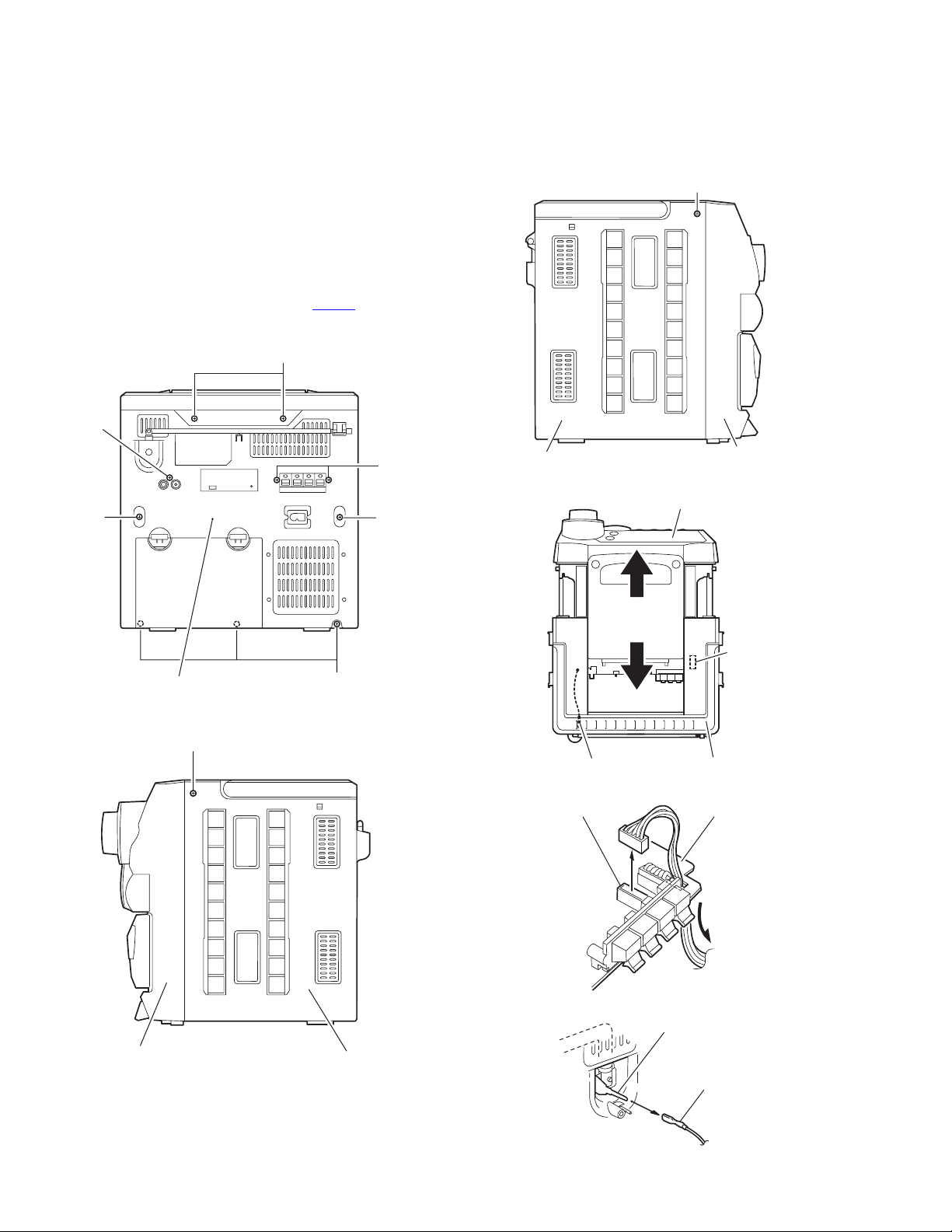
3.1 Main body
3.1.1 Removing the front cabinet section and rear cabinet
section (See Fig.1 to 6)
(1) Remove the five screws A and the five screws B on the
back of the body.
(2) Remove the screw D on each side of the body.
(3) Move the rear cabinet backward, and disconnect the an-
tenna wire from the antenna terminal on the inside of the
rear cabinet.
(4) Disconnect the wire from connector CN401
board on the front cabinet section.
on the main
B
B
D
A
Rear cabinet section
D
Fig.1
A
A
B
Rear cabinet section
ntenna terminal
CN401
Front cabinet section
Fig.3
Front cabinet section
CN401
Rear cabinet section
Fig.4
Main board
1-4 (No.MB200)
Fig.2
Fig.5
Antenna terminar
Rear cabinet sectionFront cabinet section
Antenna wire
Fig.6
Page 5
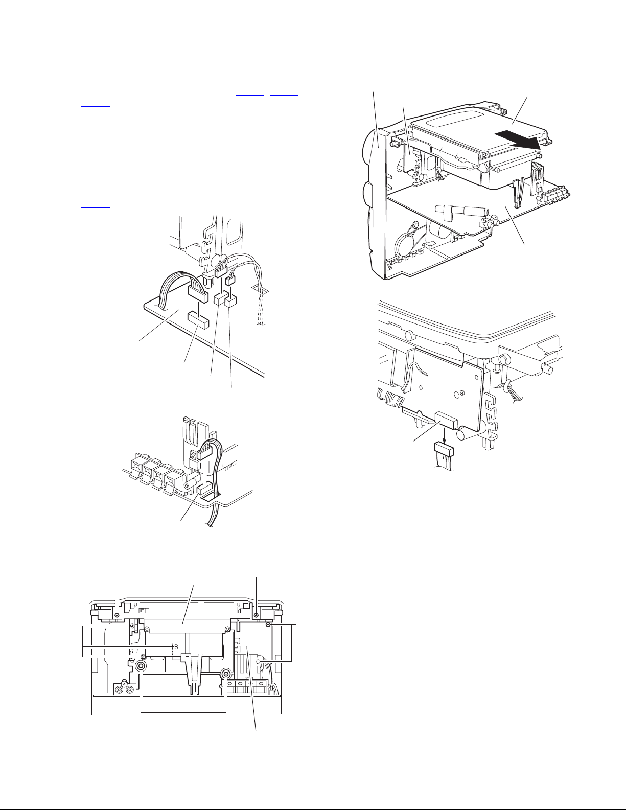
3.2 Front cabinet section
• Prior to performing the following procedure, remove the front cabinet section and rear cabinet section.
3.2.1 Removing the CD assembly section (See Fig.7 to 11)
(1) Disconnect the wires from connector CN201
on the main board.
CN203
(2) Disconnect the wire from connector CN402
board.
(3) Remove the two screws E and the two screws F attaching
the CD assembly section.
(4) Remove the five screws G attaching the LED board on the
front side of the CD assembly section.
(5) Move the CD assembly section from the front cabinet sec-
tion backward. Disconnect the card wire from connector
on the LED board.
CN601
, CN202 and
on the main
Front cabinet section
LED board
Fig.10
CD assembly section
CD assembly section
Main board
G
Main boardh
Main board
CN402
CN203
CN202
Fig.7
Fig.8
CD assembly
CN201
LED board
CN601
Fig.11
EE
G
F
LED board
Fig.9
(No.MB200)1-5
Page 6

3.2.2 Removing the LED board / main board (See Fig.2 to 16)
• Prior to performing the following procedure, remove the CD assembly section.
Caution:
Make sure to solder the short-circuit point on the CD servo
board before disconnecting the card wire from connector
on the main board and from the CD servo board. If you
CN301
don’ t observe this instruction, the pickup may be damaged.
(1) Remove the two screws H attaching the LED board.
(2) Remove the three screws J attaching the main board.
(3) Push each tab of the main board inward and remove the
main board.
(4) Move the main board and the LED board as shown in
Fig.14, and solder the short-circuit point on the CD servo
board inside the CD assembly section.
(5) Disconnect the card wire from connector CN301
main board.
(6) Disconnect the wire from the door switch at the bottom of
the CD assembly section.
Caution:
When reassembling the main board, make sure to unsolder
the short-circuit point after connecting the card wire to connector CN 301
and the CD servo board.
on the
LED board
H
CD assembly sectionav
LED board
Fig.12
H
Main board
J
1-6 (No.MB200)
Main board
Ta b
Fig.13
Page 7

LED board
CN302
CD servo board
Main board
CN301a
CD assembly
Short-circuit point
Fig.14
Card wire
Wire
Door switch
Fig.16
Unsolder
Fig.15
Short-circuit point
(No.MB200)1-7
Page 8

3.2.3 Removing the CD mechanism assembly (See Fig.17)
• Prior to performing the following procedure, remove the LED
board/main board.
(1) Disconnect the wire from the wire clamp.
(2) Remove the four screws K attaching the CD mechanism
assembly.
K
CD mechanism assemblya
Wire clamp
K
Fig.17
1-8 (No.MB200)
Page 9

3.2.4 Removing the headphone board/ switch board (See Fig.18 to 21)
• Prior to performing the following procedure, remove the CD assembly section.
(1) Pull out the volume knob on the front side.
(2) Remove the screw L attaching the bracket board on the
headphone board.
(3) Pull out the headphone board backward.
(4) Release the three bands setting the wire to the boss of the
front cabinet.
(5) Remove the eight screws M attaching the switch board.
Front assembly
Switch board
Band
Fig.20
Front assembly
M
Volume knob
Switch board
Fig.18
Headphon board
Fig.19
Band
M
Switch board
M
Fig.21
L
Headphon board
(No.MB200)1-9
Page 10

3.2.5 Removing the cassette mechanism assembly (See Fig.22 to24)
(1) Push the two eject button on the front side to open the cas-
sette door.
(2) Disconnect the wire from connector CN201, CN202 and
CN203 on the main board.
(3) Remove the six screws N attaching the cassette mecha-
nism assembly.
Cassette door
Eject button
Fig.22
Main boardh
CN203
CN202
Fig.23
Cassette mechanism assembly
Fig.24
CN201
N
N
1-10 (No.MB200)
Page 11

3.3 Rear cabinet section
• Prior to performing the following procedure, remove the front cabinet section and rear cabinet section.
3.3.1 Removing the fuse board / A/C jack / power transformer assembly (See Fig.25 to 27)
• Prior to performing the following procedure, remove the front
cabinet section and rear cabinet section.
(1) Unsolder the two wires on the battery spring.
(2) Remove the screw P attaching the fuse board.
(3) Remove the two screws Q attaching the A/C jack.
(4) Remove the four screws R attaching the power transformer
assembly.
(5) Release the four bands setting the wire to the boss of the
rear cabinet.
(6) Remove the two screws T attaching the bracket.
R
Q
A/C jack
Power transfomer
assembly
Band
Band
Battery spring
R
Fig.25
Fig.26
Power tansformer assembly
Fuse board
P
Band
Band
T
Brackt
T
Fig.27
(No.MB200)1-11
Page 12

SECTION 4
ADJUSTMENT
This service manual does not describe ADJUSTMENT.
1-12 (No.MB200)
Page 13

5.1 Block diagram
SECTION 5
TROUBLESHOOTING
Tuner
TA2149
Remote
Control
CD Pick
Up
CD Servo
TA2092
PLL
TC9257
Key Board
Remote
sensor
CD RF AMP
TA2153FN
LCD
Display
MCU/CD
TC94A09
For Tuner
For Tape
Back
Light
Source
Selector
TC9422
AUX IN
Main
Voltage
Regulator
For MCU/CD
Power AMP
TA8229PK
Rectifier
CD/MCU
Voltage
Regulator
Phone
Speaker
Power
Supply
AC IN
Tape
Section
TA8189N
TapeA
Deck
TapeB
Deck
(No.MB200)1-13
Page 14

5.2 Standard schematic diagrams
5.2.1 Main section
1-14 (No.MB200)
Page 15

(No.MB200)1-15
Page 16

5.3 Main CPU and CD servo section
1-16 (No.MB200)
Page 17

(No.MB200)1-17
Page 18

Victor Company of Japan, Limited
AV & MULTIMEDIA COMPANY AUDIO/VIDEO SYSTEMS CATEGORY 10-1,1chome,Ohwatari-machi,Maebashi-city,371-8543,Japan
(No.MB200)
Printed in Japan
WPC
 Loading...