

Page 1

CD PORTABLE COMPONENT SYSTEM
SERVICE MANUAL
PC-X290
PC-X290
HYPER-BASS
SOUND
J.................................................USA
C...........................................Canada
Contents
Page
HYPER-BASS
SOUND
Areas Suffix
Safety precautions............................................. 2 Exploded view................................................. .35
Block diagram ................................................... 3 Mechanical parts list.........................................37
Disassembly instructions................................... 4 Electrolytic parts list ......................................... 40
Troubleshooting ................................................ 5 IC lead identification
Main adjustment................................................ 7 and transistor pin out diagrams..............51
Wiring connections.......................................... 11 Voltage charts..................................................60
Printed circuit boards....................................... 12 Illustration of Packing and Parts List................62
Schematic diagrams........................................ 30
This service manual is made from 100% recycled paper.
COPYRIGHT 2000 VICTOR COMPANY OF JAPAN, LTD.
No.
APR. 2004
Page 2
PC-X290
30/MAR/200
1. This design of this product contains special hardware and many circuits and components specially for
safety purposes. For continued protection, no changes should be made to the original design unless
authorized in writing by the manufacturer. Replacement parts must be identical to those used in the
original circuits. Services should be performed by qualified personnel only.
2. Alterations of the design or circuitry of the product should not be made. Any design alterations of the
product should not be made. Any design alterations or additions will void the manufacturer warranty
and will further relieve the manufacture of responsibility for personal injury or property damage
resulting there from.
3. Many electrical and mechanical parts in the products have special safety-related characteristics.
These characteristics are often not evident from visual inspection nor can the protection afforded by
them necessarily be obtained by using replacement components rated for higher voltage, the Parts
List of Service manual. Electrical components having such features are identified by shading on the
schematics and by ( ) on the parts List in the Service Manual. The use of a substitute
replacement which does not have the same safety characteristics as the recommended replacement
parts shown in the Parts List of Service manual may create shock, fire, or other hazards.
4. The leads in the products are routed and dressed with ties, clamps, tubing, barriers and the like to
be separated from live parts, high temperature parts, moving parts and/or sharp edges for the
prevention of electric shock and fire hazard. When service is required, the original lead routing and
dress should be observed, and it should be confirmed that they have been returned to normal, after
re-assembling.
5. Leakage current check (Electrical Shock hazard testing)
After re-assembling the product, always perform an isolation check on the exposed metal Parts of the
product (antenna terminals, knobs, metal cabinet, screw heads, headphone jack, control shafts, etc.)
to be sure the product is safe to operate without danger of electrical shock.
Do not use a line isolation transformer during this check.
• Plug the AC line cord directly into the AC outlet. Using a “Leakage Current Tester”, measure the
leakage current from each exposed metal parts of the cabinet, particularly and exposed metal
part having a return path to the chassis, to a known good earth ground. Any leakage current must
not exceed 0.5mA AC (r.m.s.)
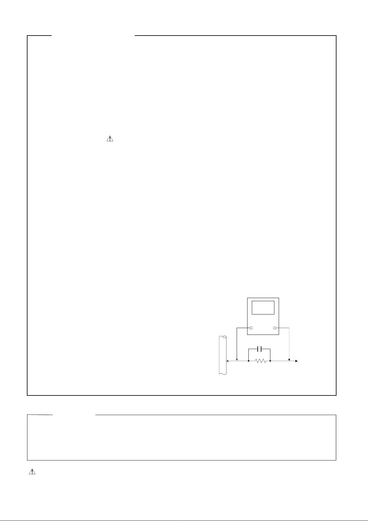
• Alternate check method
Plug the AC line cord directly into the AC outlet. Use an AC voltmeter having, 1,000 ohms per
volt or more sensitivity in the following manner. Connect a 1,500Ω 10W resistor paralleled by a
0.15µF AC-type capacitor between an exposed
metal part and a known good earth ground.
Measure the AC voltage across the resistor with
the AC voltmeter.
Move the resistor connection to eachexposed
metal part, particularly any exposed metal part
having a return path to the chassis, and
measure the AC voltage across the resistor. Now,
reverse the plug in the AC outlet and repeat
each measurement. voltage measured Any must
not exceed 0.75 V AC (r.m.s.). This corresponds
to 0.5 mA AC (r.m.s.).
Safety Precautions
0.15µF AC TYPE
1500Ω 10W
Good earth ground
AC VOLTMETER
(Having 1000
ohms/volts,
or more sensitivity
Place this
probe on
each exposed
metal part.
1. This equipment has been designed and manufactured to meet international safety standards.
2. It is the legal responsibility of the repairer to ensure that these safety standards are maintained.
3. Repairs must be made in accordance with the relevant safety standards.
4. It is essential that safety critical components are replaced by approved parts.
5. If mains voltage selector is provided, check setting for local voltage.
CAUTION
pay attention to such burrs in the case of preforming repair of this system.
Warning
2
Burrs formed during molding may be left over on some parts of the chassis. Therefore,
Page 3

PC-X290
30/MAR/2004
BLOCK DIAGRAM
TA2092
CD Servo
CD Pick
Up
CD RF AMP
TA2153FN
For Tape
For Tuner
Remote
Control
Remote
sensor
TC94A09
AUX IN
Key Board
MCU/CD
TA2149
Tuner
TC9257
PLL
Display
LCD
Back
Light
Regulator
For MCU/CD
Regulator
CD/MCU
Voltage
AC IN
Voltage
Rectifier
Supply
Main
Power AMP
TA8229PK
Power
Speaker
Phone
Selector
TC9422
Deck
Source
TA8189N
Section
Tape
TapeB
TapeA
Deck
3
Page 4
PC-X290
30/MAR/2004
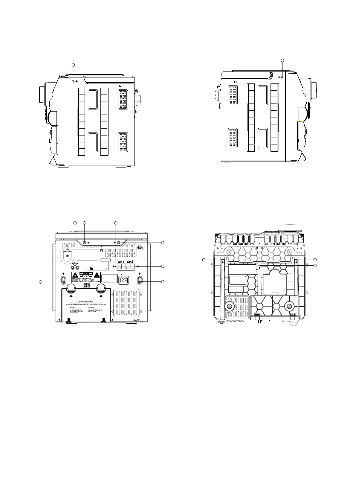
DISASSEMBLY INSTRUCTIONS
A
B
DD
L
R
ANT.
SCREW
D
OPEN
BEATCUT RESET
12
AUXIN
DO NOT USE THIS UNIT
IN DIRECT SUNLIGHT
OR LEAVE THE UNIT
IN CLOSED AUTOMOBILES
(OR YACHTS, ETC.)
WHERE IT WOULD BE EXPOSED
TO THE HIGH TEMPERATURE
(ABOVE 40 C (104 F)
OPEN
D
SPEAKERIMPEDANCEMIN 3.2
D
R
L
AC IN
D
D
C
ThisClass B digital apparatus
complieswith Canadian
ICES-003.
Cetappareil numerique de la
classeB est conforme ala
normeNMB-003 du Canada.
C
C
Removing Left and Right and Top side and back side
Remove all screws on left and right and back side
4
Page 5

TROUBLESHOOTING
Circuit Symptom Cause and Remedy
General No sound
MW No sound, weak sound
(Low sensitivity)
FM No sound, weak sound
(Low sensitivity)
Tape No sound/recording,
unsteady tape sound,
weak sound
CD Cannot read the table of
content.
no sound
• Speakers are not connected:
Check the speaker connection.
• Wrong function is selected:
Set switch to the proper position.
• Defective volume control:
Set the volume control to a proper sound level.
• Defective earphone jack:
Replace the earphone jack.
• Defect in IC404
Check voltages. Replace if necessary.
• Defect in IC401
Check voltages. Replace if necessary.
• Improper location of unit:
Rotate or reposition the unit.
• Defect in IF T101:
Check resistance, voltage, and current. Replace as needed.
• Defect AM antenna coil L103 or oscilloscope coil L104:
Replace if necessary.
• Intermediate Frequency tuning faulty:
Readjust (see “Alignment and Adjustment”).
• RF tracking faulty:
Readjust (see ‘Alignment and Adjustment”).
• Defective IC101:
Check voltages. Replace if necessary.
• Defective IC102:
Check voltages. Replace if necessary.
• Poor contact in antenna circuit:
Check resistance and resolder.
• FM antenna not connected:
Connect the built-in or external antenna.
• Defective band selector switch:
Replace or repair the switch.
• Defective IC101:
Check voltages. Replace if necessary.
• Defective IC102:
Check voltages. Replace if necessary.
• Intermediate Frequency tuning faulty:
Readjust (see “Alignment and Adjustment”).
• Poor contact in FM antenna circuit:
Resolder or repair as required.
• Dirty capstan or head:
Clean the capstan or head with alcohol.
• Irregular cassette tape winding:
Replace tape.
• Defective IC201:
Check voltage. Replace if necessary.
• Defective L203:
Check voltages. Replace if necessary.
• Cassette erasure prevention tabs broken out:
Replace tape or cover tab openings with adhesive tape.
• Disc is inserted upside down:
Insert disc correctly.
• Disc is dirty:
Wipe clean with a soft cloth.
• Disc is scratched:
Use a new disc.
• Disc is seriously warped:
Use a new disc.
PC-X290
30/MAR/2004
5
Page 6

PC-X290
Circuit Symptom Cause and Remedy
CD Cannot read the table of
content.
no sound
• A non-standard disc has been inserted:
Use only a brand name disc.
• Moisture has formed inside the CD deck:
Wait about 20 to 30 minutes.
• Defective Q407:
Check voltages. Replace if necessary.
• Defective IC301:
Check voltages. Replace if necessary.
• Defective IC302
Check voltages. Replace if necessary.
• Defective IC303:
Check voltages. Replace if necessary.
• Defect in the CD pickup mechanism:
Replace as required.
6
Page 7

30/MAR/2004
PC-X290
Main Adjustments
gggg Measuring instructions required for
adjustment
1. AM Signal generator
2. FM Signal generator
3. Inter medi ate Frequency sweep generator
4. FM stereo signal generator
5. Low-frequency oscillator (oscillation frequency
50 Hz-20 kHz, 0dB output with 600 ohm impedance)
6. Attenuator (600 ohm impedance)
7. Electronic voltmeter
8. Distortion meter
9. Torque gauge (cassette for CTG-N)
10. Wow & flut ter meter
11. Frequency counter meter
◊
Test tape
•
Playback tape
MTT-111NS (tape speed, wow flutter)
MTT-112BN (reference level)
MTT-257C (playback frequency)
MTT-113CN
•
Recording tape
MTT-501
•
Power supply voltage
AC110V-120V 60Hz
gggg Measuring instruments
•
Radio section
◊ FM 1 kHz, 22.5 kHz deviation
◊ FM STEREO: 1 kHz, 67.5 kHz deviation
pilot signal 7.5 k Hz.
◊ AM: 1 kHz, 30% modulati on
◊ Reference output:
Speaker output: 0dB (2 V )3. 2 ohm
H. Phone output: - 10 dB (0. 245V )/32 ohm
7
•
Amplifier section
◊ Reference output:
Speaker output 0 dB (2 V)/ 3.2 ohm
H. Phone output – 10 dB (0.245V)/32 ohm
•
CD section
◊ Test disc: SONY Yeds 7 Type 3
PHILIPS SBC-444A
A-BEX: TCD-731R
TCD-712R
TCD-785
Page 8

PC-X290
Cassette Amplifier Section
!
Item Measuring Condition Check and adjustment procedure Standard value Adjusting part
Head azimuth
adjustment
PB frequency
response check
Bias frequency
check
REC and PB
frequency
response
adjustment
• Tes t tape:
MTT113CN (8 kHz)
• S i gnal out put
terminal:
PHONES
(with 32 ohm load)
• Tes t tape:
MTT257C
• S i gnal out put
terminal:
PHONES
(with 32 ohm load)
• Tape: Normal
• S i gnal out put
terminal: Cassette
REC./PLAY HEAD
• Tes t tape: MTT-501
• Si gnal i nput FM22.5
DEV 60dBµ with
Emphasis
• s i gnal output
terminal: PHONES
(with 32 ohm load)
1. Play back the test MTT113CN (8 kHz).
2. Adjust the head azimuth adjusting screw so that
the phase difference between the R and L
channels is minimized at an output level that is
within ±2 dB of the maximum output level . After
this adjustment , lock the head azimuth adjust i ng
screw with screw sealant to cover m ore t han a
half of the screw head.
3. When the head azimuth is m aladj ust ed, c orrect it
with the head azimuth adjusting screw.
Play back the test tape MTT257C while con-firming
that deviation between the 1 kHz signal and 8 k Hz
signal should be 0 (+3~-6) dB.
Set the TUNER or CD function and with TA PE to
record. check to see if the frequency at the
measuring point R201 or R202 is 82 kHz ±1 k Hz. if
not adjust L203 until the frequency counter
indicates 82 kHz ± 1 k Hz.
At TUNER, set the BAND to the FM posi tion, and
record the reference 1 kHz signal and 8 kHz signal
alternately repeatedly. While playing back the
recorded signal differ from that of the 1 kHz signal
by within 0 (+3~-6) dB.
• Output level:
• Within ±2 dB of
maximum output
level
• P hase difference
L and R
channels:
Minimum
Deviation between
1 kHz and 8 kHz:
0 (+3~-6) dB
L203,
Level difference
between REC and
PB:Wit hi n 0 (+3~-6)
dB.
Head azimuth
adjusting
screw (To be
used only
after head
replacement)
See Fig 3-1
R201/R202
See Fig 3-2
8
Page 9

PC-X290
! Tuner Section
Item Measuring
Condition
AM IF
adjustment
AM tracking
adjustment
FM tracking
adjustment
Signal input:
Loop ANTENNA
Signal output:
IC101 PIN (16)
Signal input:
Loop antenna
PHONES (with 32
ohm Load)
Signal input:
Antenna
Signal output:
IC101 PIN (16)
1. Set the intermediate frequency sweep generator to
2. Adjust the T101 for maxim um and center output
1.Set the TUNER at 530 KHz adjus t L104 until the
2. Set the TUNER at 1710 KHz, Chec k the pin of
R107 Voltage at 7.5V ±0.5V.
3. Set the TUNER and S/G at 610KHz, adjust L103
4. Set the TUNER and S/G at 1400K Hz, adj ust TC102
5. Repeat the above steps 3 and 4.
1.Set the TUNER at 87.5MHz adjust L102 until the
2.Set the TUNER at 108MHz, Check the pin of
3. Set the TUNER and S/G at 90. 1MHz, adj ust L101
4.Set the TUNER and S/G at 106.1MHz, adjust
5.Repeat the above steps 3 and 4.
Check and adjustment procedure Standard value Adjusting part
• T101
AM 450 kHz.
test pin of R107
for maximum output.
for maximum output.
test pin of R105
R105 Voltage at 7.5V ±1V.
for maximum output.
TC101 for maximum output.
voltage at 1.5 V ±0.05V.
voltage at 2.3 V ±0.05V.
• L104
• L102
See Fig 3-2
• L103
• TC102
See Fig 3-2
• L101
• TC101
See Fig 3-2
9
Page 10

PC-X290
Location of adjusting parts
! Cassette mechani sm section
Figure 3-1 Head Output Signal
Main board assembly
•
3
0
1
L
L104
TC102
L102
IC101
1
0
2
C
I
L101
1
0
1
C
T
T101
R201
3
0
2
L
Figure 3-2
R202
10
Page 11

PC-X290
WIRING CONNECTIONS
11
Page 12

PC-X290
JVC ASIA PTE., LTD.
101 Thomson Road, 28-04 United Square Singapore 307591.
(No. )
Printed in Japan
0001 (V)
 Loading...