

Page 1
SERVICE MANUAL
MB675<Rev.002>20089SERVICE MANUAL
NX-PN7J,NX-PN7C,NX-PN7B,NX-PN7E,
NX-PN7US,NX-PN7UW,NX-PN7UJ
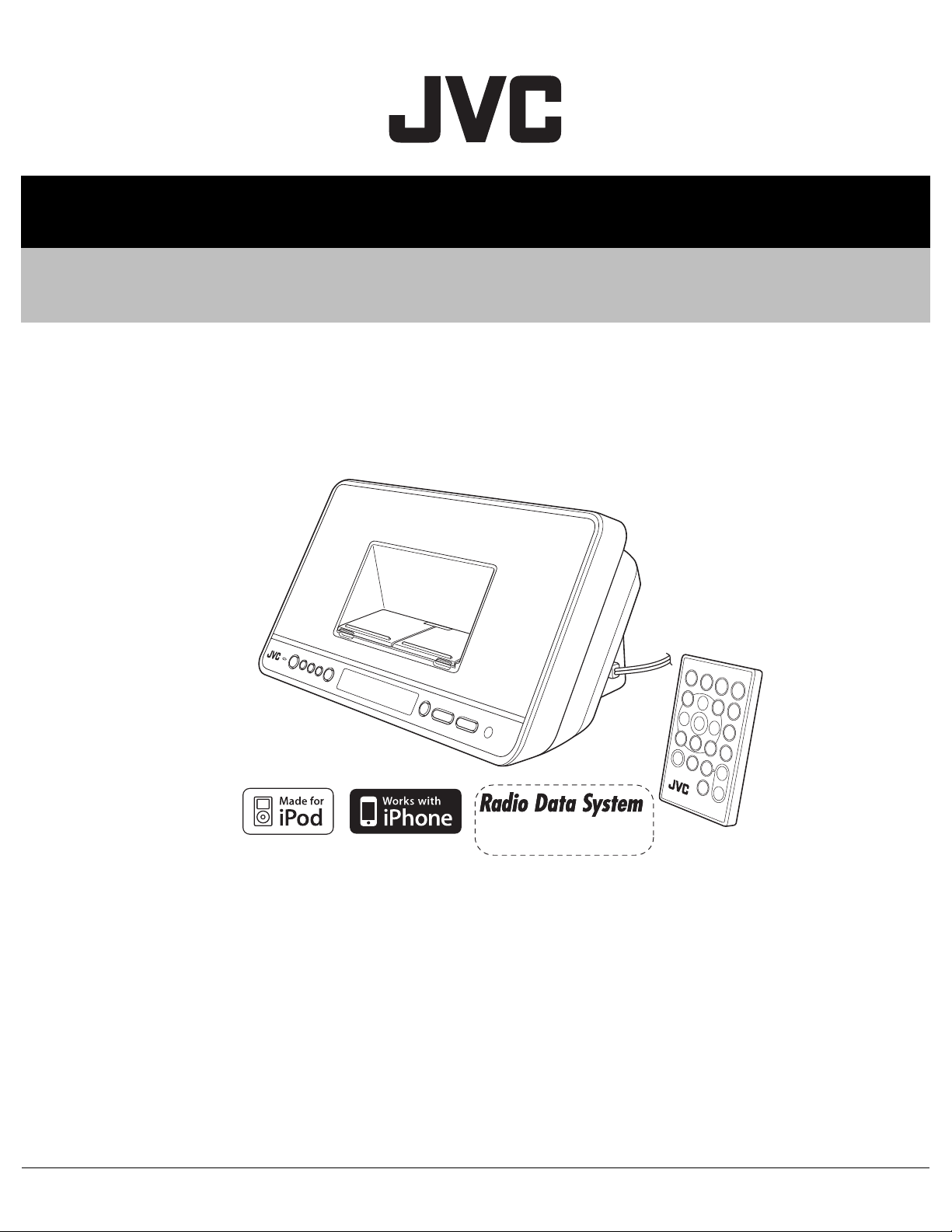
COMPACT COMPONENT SYSTEM
NX-PN7EN,NX-PN7EV,NX-PN7A,
NX-PN7B, NX-PN7E
NX-PN7EN, NX-PN7EV
COPYRIGHT © 2008 Victor Company of Japan, Limited
Lead free solder used in the board (material : Sn-Ag-Cu, melting point : 219 Centigrade)
TABLE OF CONTENTS
1 PRECAUTION. . . . . . . . . . . . . . . . . . . . . . . . . . . . . . . . . . . . . . . . . . . . . . . . . . . . . . . . . . . . . . . . . . . . . . . . . 1-5
2 SPECIFIC SERVICE INSTRUCTIONS. . . . . . . . . . . . . . . . . . . . . . . . . . . . . . . . . . . . . . . . . . . . . . . . . . . . . . 1-7
3 DISASSEMBLY . . . . . . . . . . . . . . . . . . . . . . . . . . . . . . . . . . . . . . . . . . . . . . . . . . . . . . . . . . . . . . . . . . . . . . . 1-7
4 ADJUSTMENT . . . . . . . . . . . . . . . . . . . . . . . . . . . . . . . . . . . . . . . . . . . . . . . . . . . . . . . . . . . . . . . . . . . . . . . 1-10
5 TROUBLESHOOTING . . . . . . . . . . . . . . . . . . . . . . . . . . . . . . . . . . . . . . . . . . . . . . . . . . . . . . . . . . . . . . . . . 1-10
COPYRIGHT © 2008 Victor Company of Japan, Limited
No.MB675<Rev.002>
2008/9
Page 2
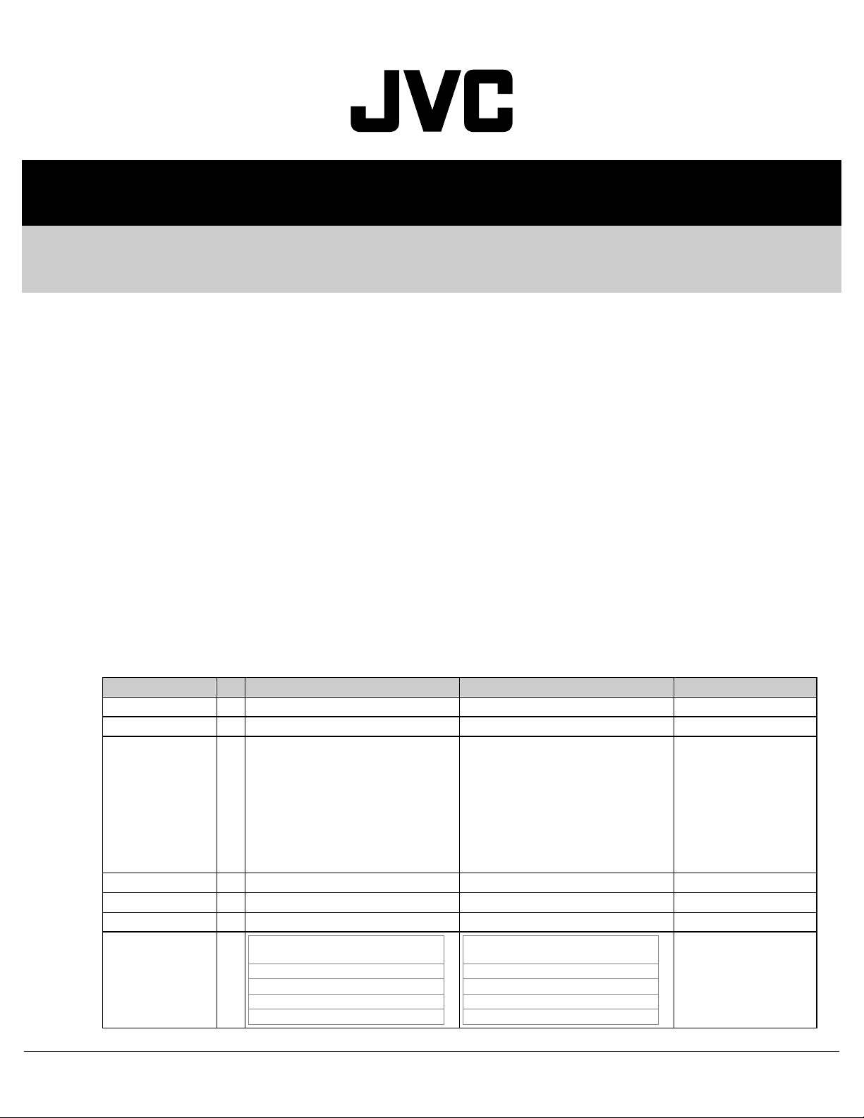
REVISION INFORMATION
COMPACT COMPONENT SYSTEM
NX-PN7J, NX-PN7C, NX-PN7B, NX-PN7E,
NX-PN7EN, NX-PN7EV, NX-PN7A, NX-PN7US,
NX-PN7UW, NX-PN7UJ
■ OVERVIEW
Add NX-PN7B, NX-PN7E, NX-PN7EN, NX-PN7EV, NX-PN7A, NX-PN7US, NX-PN7UW and
NX-PN7UJ
■ DETAILS
COVER SECTION
Title Line No.MB675<Rev.001> No.MB675<Rev.002> Description
Revision Rev.001 Rev.002
Issue Date 2008/07 2008/09
Model No. NX-PN7C,
Cover Illustration ILLUSTRATION(mb675_0001.png) ILLUSTRATION(mb675_0001.png)
Category Audio/Video Systems category Audio/Video Systems Division
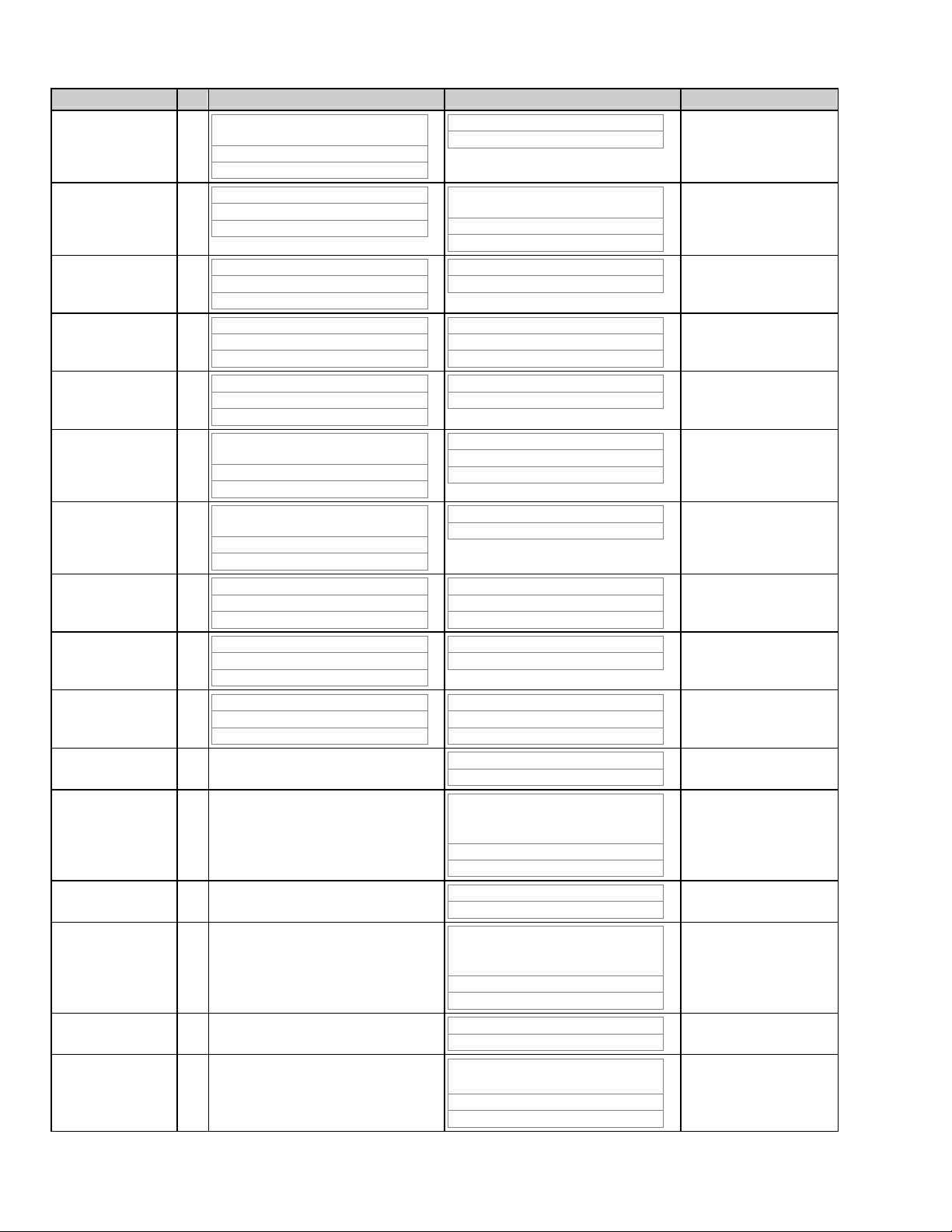
SPECIFICATION 1 NX-PN7J,C
10
NX-PN7J
Dock A and B for iPod
* Only for still picture.
Compatible iPod types
iPod nano 1GB/2GB/4GB
yes
no
NX-PN7A,
NX-PN7B,
NX-PN7C,
NX-PN7E,
NX-PN7EN,
NX-PN7EV,
NX-PN7J,
NX-PN7UJ,
NX-PN7US,
NX-PN7UW
Dock A and B for iPod
* Only for still picture.
Compatible iPod types
iPod nano 1GB/2GB/4GB
Audio
yes
COPYRIGHT © 2008 Victor Company of Japan, Limited
MB675-R002
2008/09
Page 3
Title Line No.MB675<Rev.001> No.MB675<Rev.002> Description
11
12
13
14
15
16
17
18
19
20
21 -
22 -
iPod nano (2nd Generation)
2GB/4GB/8GB
yes
no
iPod nano (3rd Generation) 4GB/8GB
yes
yes
iPod mini 4GB
yes
no
iPod mini (2nd Generation) 4GB/ 6GB
yes
no
iPod (4th Generation) 20GB/40GB
yes
no
iPod photo (4th Generation)
20GB/30GB/40GB/60GB
yes
yes*
iPod video (5th Generation)
30GB/60GB/80GB
yes
yes
iPod classic 80GB/160GB
yes
yes
iPod touch 8GB/16GB/32GB
yes
yes
iPhone 4GB/8GB/16GB
yes
yes
Video
no
iPod nano (2nd Generation)
2GB/4GB/8GB
Audio
yes
Video
no
iPod nano (3rd Generation) 4GB/8GB
Audio
yes
Video
yes
iPod mini 4GB
Audio
yes
Video
no
iPod mini (2nd Generation) 4GB/ 6GB
Audio
yes
Video
no
iPod (4th Generation) 20GB/40GB
Audio
yes
Video
no
iPod photo (4th Generation)
20GB/30GB/40GB/60GB
23 -
24 -
25 -
26 -
2 (MB675-R002)
Audio
yes
Video
yes*
iPod video (5th Generation)
30GB/60GB/80GB
Audio
yes
Video
yes
iPod classic 80GB/160GB
Audio
yes
Page 4

Title Line No.MB675<Rev.001> No.MB675<Rev.002> Description
27 -
28 -
29 -
30 -
31 -
54 - NX-PN7BEENEV
55 -
56 -
57 58 -
59 60 61 -
62 -
63 -
64 -
65 -
66 -
67 -
68 -
69 -
Video
yes
iPod touch 8GB/16GB/32GB
Audio
yes
Video
yes
iPhone 4GB/8GB/16GB
Audio
yes
Video
yes
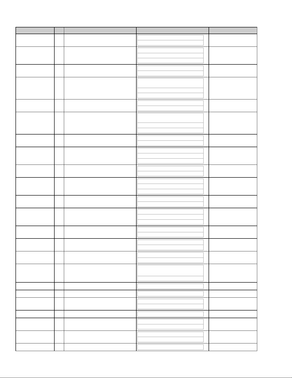
Amplifier
Output Power
10 W (5 W + 5 W) at 8 Ω (10% THD)
(IEC268-3)
Terminals
AUDIO IN
Input Sensitivity/
Impedance (1 kHz)
LEVEL 1: 500 mV/47 kΩ
LEVEL 2: 250 mV/47 kΩ
LEVEL 3: 125 mV/47 kΩ
Dock A and B for iPod
* Only for still picture.
Compatible iPod types
iPod nano 1GB/2GB/4GB
Audio
yes
Video
no
iPod nano (2nd Generation)
2GB/4GB/8GB
Audio
yes
Video
no
iPod nano (3rd Generation) 4GB/8GB
Audio
yes
Video
yes
iPod mini 4GB
Audio
yes
Video
no
iPod mini (2nd Generation) 4GB/ 6GB
Audio
yes
(MB675-R002) 3
Page 5
Title Line No.MB675<Rev.001> No.MB675<Rev.002> Description
70 -
71 -
72 -
73 -
74 -
75 -
76 -
77 -
78 -
79 -
80 -
81 -
82 -
83 -
84 -
85 -
Video
no
iPod (4th Generation) 20GB/40GB
Audio
yes
Video
no
iPod photo (4th Generation)
20GB/30GB/40GB/60GB
Audio
yes
Video
yes*
iPod video (5th Generation)
30GB/60GB/80GB
Audio
yes
Video
yes
iPod classic 80GB/160GB
Audio
yes
Video
yes
iPod touch 8GB/16GB/32GB
Audio
yes
Video
yes
iPhone 4GB/8GB/16GB
Audio
yes
Video
yes
Output power (each iPod)
DC 5 V 500 mA
VIDEO OUT (For iPod)
Composite
PHONES
86 87 88 -
89 90 -
91 -
92 -
4 (MB675-R002)
32Ω 1 kΩ
15 mW/ch output into 32 Ω
Tuner
FM tuning range
87.50 MHz - 108.00 MHz
Unit
Dimensions (W/H/D)
318 mm × 148 mm × 154 mm
Mass
Approx. 1.6 kg
Speaker Specifications
Page 6
Title Line No.MB675<Rev.001> No.MB675<Rev.002> Description
93 -
94 -
95 -
96 97 -
98 -
99 -
100 -
101 102 103 -
105 - Design and specifications are subject to
106 - NX-PN7AUSUJUW
107 -
108 -
109 110 -
111 112 113 -
114 -
115 -
116 -
Type
Full range bass-reflex type
Speakers
7 cm cone × 2
Impedance
8 Ω
Power Specifications
Power Source
DC 10.7 V 3 A (EXTERNAL DC IN)
AC Adaptor (AA-R1001)
INPUT
AC 110 - 240 V 50 Hz/60 Hz 1 A
OUTPUT
DC 10.7 V 3 A 32.1 VA
Power Consumption
35 W (power on mode)
4 W or less (in Standby mode)
1 W or less (in ECO mode)
19 W (in Standby mode with two iPod
devices connected.)
change without notice.
Amplifier
Output Power
10 W (5 W + 5 W) at 8Ω(10% THD)
(IEC268-3)
Terminals
AUDIO IN
Input Sensitivity/
Impedance (1 kHz)
LEVEL 1: 500 mV/47 kΩ
LEVEL 2: 250 mV/47 kΩ
LEVEL 3: 125 mV/47 kΩ
Dock A and B for iPod
* Only for still picture.
Compatible iPod types
iPod nano 1GB/2GB/4GB
Audio
yes
Video
no
iPod nano (2nd Generation)
2GB/4GB/8GB
Audio
yes
Video
no
(MB675-R002) 5
Page 7
Title Line No.MB675<Rev.001> No.MB675<Rev.002> Description
117 -
118 -
119 -
120 -
121 -
122 -
123 -
124 -
125 -
126 -
127 -
128 -
129 -
130 -
131 -
132 -
133 -
134 -
135 -
136 -
iPod nano (3rd Generation) 4GB/8GB
Audio
yes
Video
yes
iPod mini 4GB
Audio
yes
Video
no
iPod mini (2nd Generation) 4GB/ 6GB
Audio
yes
Video
no
iPod (4th Generation) 20GB/40GB
Audio
yes
Video
no
iPod photo (4th Generation)
20GB/30GB/40GB/60GB
Audio
yes
Video
yes*
iPod video (5th Generation)
30GB/60GB/80GB
Audio
yes
Video
yes
iPod classic 80GB/160GB
Audio
yes
Video
yes
iPod touch 8GB/16GB/32GB
Audio
yes
Video
yes
iPhone 4GB/8GB/16GB
Audio
yes
Video
yes
Output power (each iPod)
DC 5 V 500 mA
VIDEO OUT (For iPod)
Composite
6 (MB675-R002)
Page 8

Title Line No.MB675<Rev.001> No.MB675<Rev.002> Description
137 -
138 139 140 -
141 142 -
143 -
144 145 -
146 -
147 -
148 149 -
150 -
151 -
152 -
PHONES
32Ω 1 kΩ
15 mW/ch output into 32 Ω
Tuner
FM tuning range
87.50 MHz-108.00 MHz
Unit
Dimensions (W/H/D)
318 mm × 148 mm × 154 mm
Mass
Approx. 1.6 kg
Speaker Specifications
Type
Full range bass-reflex type
Speakers
7 cm cone × 2
Impedance
8 Ω
Power Specifications
Power Source
DC 10.7 V 3 A (EXTERNAL DC IN)
AC Adaptor (AA-R1001)
INPUT
AC 110 - 240 V , 50 Hz/60 Hz 1 A
OUTPUT
DC 10.7 V 3 A
Power Consumption:
35 W (power on mode)
153 154 155 -
157 - Design and specifications are subject to
4 W or less (in Standby mode)
1 W or less (in ECO mode)
19 W (in Standby mode with two iPod
devices connected.)
change without notice.
SECTION 1 PRECAUTION
Title Line No.MB675<Rev.001> No.MB675<Rev.002> Description
1.1 Safety
Precautions
1.5 Safety
Precautions (U.K
only)
1 - 1. This design of this product contains
8 ILLUSTRATION(LXM-SA007-
001_01.png)
T - 1.5 Safety Precautions (U.K only)
ILLUSTRATION(LXM-SA009001_01.png)
special hardware and many circuits and
components specially for safety
purposes. For continued protection, no
changes should be made to the original
design unless authorized in writing by the
manufacturer. Replacement parts must
be identical to those used in the original
circuits.
(MB675-R002) 7
Page 9

Title Line No.MB675<Rev.001> No.MB675<Rev.002> Description
2 - 2. Any unauthorised design alterations or
additions will void the manufacturer's
guarantee; furthermore the manufacturer
cannot accept responsibility for personal
injury or property damage resulting
therefrom.
3 - 3. Essential safety critical components
are identified by
( ILLUSTRATION(kigo001.png) ) on the
Parts List and by shading on the
schematics, and must never be replaced
by parts other than those listed in the
manual. Please note however that many
electrical and mechanical parts in the
product have special safety related
characteristics. These characteristics are
often not evident from visual inspection.
Parts other than specified by the
manufacturer may not have the same
safety characteristics as the
recommended replacement parts shown
in the Parts List of the Service Manual
and may create shock, fire, or other
hazards.
4 - 4. The leads in the products are routed
and dressed with ties, clamps, tubings,
barriers and the like to be separated from
live parts, high temperature parts, moving
parts and/or sharp edges for the
prevention of electric shock and fire
hazard. When service is required, the
original lead routing and dress should be
observed, and it should be confirmed that
they have been returned to normal, after
re-assembling.
1.5.1 Warning T - 1.5.1 Warning
1 - 1. Service should be performed by
qualified personnel only.
2 - 2. This equipment has been designed
and manufactured to meet international
safety standards.
3 - 3. It is the legal responsibility of the
repairer to ensure that these safety
standards are maintained.
4 - 4. Repairs must be made in accordance
with the relevant safety standards.
5 - 5. It is essential that safety critical
components are replaced by approved
parts.
6 - 6. If mains voltage selector is provided,
check setting for local voltage.
7 - ILLUSTRATION(LXM-SA009-
001_02.png)
STANDARD SCHEMATIC DIAGRAMS
Description of Major ICs
Diagram Name No.MB675<Rev.001> No.MB675<Rev.002> Description
Menu - U302: BI102024X
BI102024X.xml
Menu - U702: BI103952X
BI103952X.xml
Menu - U310: BI113231X
BI113231X.xml
8 (MB675-R002)
Page 10

Diagram Name No.MB675<Rev.001> No.MB675<Rev.002> Description
Menu - U705: BI119711X
BI119711X.xml
Menu - U703: BI117371X
NJM2233BM.xml
Menu - U303: BI126541V
TDA7266SA.xml
(MB675-R002) 9
Page 11

PARTS LIST
r
r
MODEL No. LIST
Model No. No.MB675<Rev.002>
NX-PN7A 07
NX-PN7B 03
NX-PN7C 02
NX-PN7E 04
NX-PN7EN 05
NX-PN7EV 06
NX-PN7J 01
NX-PN7UJ 0A
NX-PN7US 08
NX-PN7UW 09
General assembly [M1]
Symbol or
!
M1 6 ------------ BI1005469102X1 FRONT CABINET (Addition) 1 07,08,09,0A
M1 13 ------------ BI1005450302X1 DISPLAY WINDOW (Addition) 1 07,08,09,0A
M1 14 ------------ BI1005480102X1 AD ORNAMENT (Addition) 1 07,08,09,0A
M1 35 ------------ BI2035200101X1 BRACKET (Addition) 1 03,04,05,06,07,08,09,0A
<Rev.001> <Rev.002>
Electrical parts list Main board [01]
Symbol o
!
01 U801 ------------ BI100NS9543000 IC (Addition) 1 03,04,05,06
01 Q323 ------------ DTC114TK DIGI TRANSISTOR (Addition) 1 03,04,05,06,07,08,09,0A
01 D324 ------------ MTZJ20B Z DIODE (Addition) 1 03,04,05,06,07,08,09,0A
01 C437 ------------ BICC475250KA02 C CAPACITOR (Addition) 1 03,04,05,06,07,08,09,0A
! 01 R303 BIRCW0100050X ------------ RESISTOR (Deletion) 1 01,02
! 01 R303 ------------ BIRCW0100050X RESISTOR (Addition) 1 01,03,04,05,06,07,08,09,0A
01 R330 ------------ BIRC0000025A00 C RESISTOR (Addition) 1 03,04,05,06,07,08,09,0A
01 R357 ------------ BIRC0000105A00 C RESISTOR (Addition) 1 03,04,05,06
01 R357 ------------ BIRC1830105A00 C RESISTOR (Addition) 1 07,08,09,0A
01 CN302A ------------ BI12S30063X SOCKET CONN (Addition) 1 03,04,05,06
01 CN307A ------------ BI12P30293X CONNECTOR (Addition) 1 03,04,05,06,07,08,09,0A
01 RN801 ------------ BIRN1020105A40 C RESISTOR (Addition) 1 03,04,05,06
<Rev.001> <Rev.002>
Part No.
Part No.
Part Name Description Qty Models
Part Name Description Qty Models
DC jack board [05]
Symbol or
!
05 CN307B ------------ BI240V03396M01 CONNECTOR (Addition) 1 03,04,05,06,07,08,09,0A
05 JK204 ------------ BI23A0541X DC POWER JACK (Addition) 1 03,04,05,06,07,08,09,0A
<Rev.001> <Rev.002>
Part No.
Part Name Description Qty Models
Packing and accessories [M3]
Symbol o
!
M3 A1 ------------ BI440002109000 INST BOOK (Addition) 1 03
M3 A1 ------------ BI440002089000 INST BOOK (Addition) 1 04
M3 A1 ------------ BI440002108000 INST BOOK (Addition) 1 05
M3 A1 ------------ BI440002126000 INST BOOK (Addition) 1 06
M3 A1 ------------ BI440002127000 INST BOOK (Addition) 1 07
M3 A1 ------------ BI440002107000 INST BOOK (Addition) 1 08
M3 A1 ------------ BI440002092000 INST BOOK (Addition) 1 09
M3 A1 ------------ BI440002125000 INST BOOK (Addition) 1 0A
M3 A3 ------------ BI400083291001 REGISTER CARD (Addition) 1 03
M3 A4 ------------ ------------ WARRANTY CARD (Addition) 1 03,04,05,06
M3 A4 ------------ ------------ WARRANTY CARD (Addition) 1 07,08,09,0A
M3 A5 ------------ BIG60NXPN702BX REMOCON UNIT (Addition) 1 03,04,05,06
M3 A8 ------------ ------------ BATTERY (Addition) 1 01,02,03,04,05,06,07,08,09,0A
! M3 A9 ------------ BI212011030001 AC ADAPTOR (Addition) 1 03
! M3 A9 ------------ BI212011023001 AC ADAPTOR (Addition) 1 04,05,06,08,09,0A
! M3 A9 ------------ BI212011029001 AC ADAPTOR (Addition) 1 07
M3 A10 ------------ ------------ WARRANTY CARD (Addition) 1 07,08,09,0A
! M3 A11 ------------ BI23A0095X CONVERSION
<Rev.001> <Rev.002>
Part No.
Part Name Description Qty Models
(Addition) 1 08,09,0A
PLUG
10 (MB675-R002)
Page 12

Symbol o
r
!
M3 P1 ------------ BI410011378001 CARTON (Addition) 1 03,04,05,06
M3 P1 ------------ BI410011411001 CARTON (Addition) 1 07,08,09,0A
M3 XXXXX ------------ ------------ BATTERY (Deletion) 1 01,02
<Rev.001> <Rev.002>
Part No.
Part Name Description Qty Models
(MB675-R002) 11
Page 13

SPECIFICATION
NX-PN7J,C
Amplifier
Output Power without iPod
with an iPod
with two iPod devices
AUDIO IN Input Sensitivity/
Impedance (1 kHz)
Dock A and B for iPod
* Only for still picture.
Output power (each iPod) DC 5 V=500 mA
VIDEO OUT (For iPod) Composite
PHONES 32 Ω - 1 kΩ
FM tuning range 87.5 MHz - 108.0 MHz (100 kHz channel space)
AM tuning range 530 kHz - 1710 kHz (10 kHz channel space)
Dimensions (W/H/D) 318 mm × 148 mm × 154 mm (12-9/16 inches × 5-7/8 inches × 6-1/8 inches)
Mass Approx. 2.6 kg (5.8 lbs)
Type Full range bass-reflex type
Speakers 7 cm (2-13/16 inches) cone × 2
Impedance 8 Ω
Power Requirements AC 120V~60 Hz, 0.4 A
Power Consumption 35 W (power on mode)
Compatible iPod types iPod nano 1GB/2GB/4GB Audio yes
7.5W per channel min. RMS driven into 8 Ω at 1 kHz with no more than 10% total harmonic distortion
7.0W per channel min. RMS driven into 8 Ω at 1 kHz with no more than 10% total harmonic distortion
6.3W per channel min. RMS driven into 8 Ω at 1 kHz with no more than 10% total harmonic distortion
Terminals
LEVEL 1: 500 mV/47 kΩ
LEVEL 2: 250 mV/47 kΩ
LEVEL 3: 125 mV/47 kΩ
Video no
iPod nano (2nd Generation) 2GB/4GB/8GB Audio yes
Video no
iPod nano (3rd Generation) 4GB/8GB Audio yes
Video yes
iPod mini 4GB Audio yes
Video no
iPod mini (2nd Generation) 4GB/ 6GB Audio yes
Video no
iPod (4th Generation) 20GB/40GB Audio yes
Video no
iPod photo (4th Generation) 20GB/30GB/40GB/60GB Audio yes
Video yes*
iPod video (5th Generation) 30GB/60GB/80GB Audio yes
Video yes
iPod classic 80GB/160GB Audio yes
Video yes
iPod touch 8GB/16GB/32GB Audio yes
Video yes
iPhone 4GB/8GB/16GB Audio yes
Video yes
15 mW/ch output into 32 Ω
Tuner
Unit
Speaker Specifications
Power Specifications
4 W or less (in Standby mode)
2 W or less (in ECO mode)
19 W (in Standby mode with two iPod devices connected.)
Design and specifications are subject to change without notice.
1-2 (No.MB675<Rev.002>)
Page 14

NX-PN7BEENEV
Amplifier
Output Power 10 W (5 W + 5 W) at 8 Ω (10% THD) (IEC268-3)
Terminals
AUDIO IN Input Sensitivity/
Impedance (1 kHz)
Dock A and B for iPod
* Only for still picture.
Output power (each iPod) DC 5 V 500 mA
VIDEO OUT (For iPod) Composite
PHONES 32Ω 1 kΩ
FM tuning range 87.50 MHz - 108.00 MHz
Dimensions (W/H/D) 318 mm × 148 mm × 154 mm
Mass Approx. 1.6 kg
Type Full range bass-reflex type
Speakers 7 cm cone × 2
Impedance 8 Ω
Power Source DC 10.7 V 3 A (EXTERNAL DC IN)
AC Adaptor (AA-R1001) INPUT AC 110 - 240 V 50 Hz/60 Hz 1 A
Power Consumption 35 W (power on mode)
Compatible iPod types iPod nano 1GB/2GB/4GB Audio yes
OUTPUT DC 10.7 V 3 A 32.1 VA
4 W or less (in Standby mode)
1 W or less (in ECO mode)
19 W (in Standby mode with two iPod devices connected.)
LEVEL 1: 500 mV/47 kΩ
LEVEL 2: 250 mV/47 kΩ
LEVEL 3: 125 mV/47 kΩ
iPod nano (2nd Generation) 2GB/4GB/8GB Audio yes
iPod nano (3rd Generation) 4GB/8GB Audio yes
iPod mini 4GB Audio yes
iPod mini (2nd Generation) 4GB/ 6GB Audio yes
iPod (4th Generation) 20GB/40GB Audio yes
iPod photo (4th Generation) 20GB/30GB/40GB/60GB Audio yes
iPod video (5th Generation) 30GB/60GB/80GB Audio yes
iPod classic 80GB/160GB Audio yes
iPod touch 8GB/16GB/32GB Audio yes
iPhone 4GB/8GB/16GB Audio yes
15 mW/ch output into 32 Ω
Tuner
Unit
Speaker Specifications
Power Specifications
Video no
Video no
Video yes
Video no
Video no
Video no
Video yes*
Video yes
Video yes
Video yes
Video yes
Design and specifications are subject to change without notice.
(No.MB675<Rev.002>)1-3
Page 15

NX-PN7AUSUJUW
Amplifier
Output Power 10 W (5 W + 5 W) at 8Ω(10% THD) (IEC268-3)
Terminals
AUDIO IN Input Sensitivity/
Impedance (1 kHz)
Dock A and B for iPod
* Only for still picture.
Output power (each iPod) DC 5 V 500 mA
VIDEO OUT (For iPod) Composite
PHONES 32Ω 1 kΩ
FM tuning range 87.50 MHz-108.00 MHz
Dimensions (W/H/D) 318 mm × 148 mm × 154 mm
Mass Approx. 1.6 kg
Type Full range bass-reflex type
Speakers 7 cm cone × 2
Impedance 8 Ω
Power Source DC 10.7 V 3 A (EXTERNAL DC IN)
AC Adaptor (AA-R1001) INPUT AC 110 - 240 V , 50 Hz/60 Hz 1 A
Power Consumption: 35 W (power on mode)
Compatible iPod types iPod nano 1GB/2GB/4GB Audio yes
OUTPUT DC 10.7 V 3 A
LEVEL 1: 500 mV/47 kΩ
LEVEL 2: 250 mV/47 kΩ
LEVEL 3: 125 mV/47 kΩ
iPod nano (2nd Generation) 2GB/4GB/8GB Audio yes
iPod nano (3rd Generation) 4GB/8GB Audio yes
iPod mini 4GB Audio yes
iPod mini (2nd Generation) 4GB/ 6GB Audio yes
iPod (4th Generation) 20GB/40GB Audio yes
iPod photo (4th Generation) 20GB/30GB/40GB/60GB Audio yes
iPod video (5th Generation) 30GB/60GB/80GB Audio yes
iPod classic 80GB/160GB Audio yes
iPod touch 8GB/16GB/32GB Audio yes
iPhone 4GB/8GB/16GB Audio yes
15 mW/ch output into 32 Ω
Tuner
Unit
Speaker Specifications
Power Specifications
4 W or less (in Standby mode)
1 W or less (in ECO mode)
19 W (in Standby mode with two iPod devices connected.)
Video no
Video no
Video yes
Video no
Video no
Video no
Video yes*
Video yes
Video yes
Video yes
Video yes
Design and specifications are subject to change without notice.
1-4 (No.MB675<Rev.002>)
Page 16

SECTION 1
PRECAUTION
1.1 Safety Precautions
(1) This design of this product contains special hardware and
many circuits and com ponen ts sp ecial ly for s afety purp oses. For continued protection, no changes should be made
to the original design unless authorized in writing by the
manufacturer. Replacement parts must be identical to
those used in the original circuits. Services should be performed by qualified personnel only.
(2) Alterations of the design or circuitry of the product should
not be made. Any design alterations of the product should
not be made. Any design alterations or additions will void
the manufacturers warranty and will further relieve the
manufacture of respo nsibility for pe rsonal injury or property
damage resulting therefrom.
(3) Many electrical and mechanical parts in the products have
special safety-related characteristics. These characteristics are often not evident from vi sual insp ection nor can the
protection afforded by them nec essaril y be obtained by using replacement compon ents rated for higher voltag e, wattage, etc. Replacement parts which have these special
safety characteristic s ar e identified in the Parts L is t of Service Manual. Electrical components having such features
are identified by shading on the schemat ics and by ( ) on
the Parts List in the Servic e Manual. The use o f a substitute
replacement which does not have the s am e safety characteristics as the recommended replacement parts shown in
the Parts List of Service Manual may create shock, fire, or
other hazards.
(4) The leads in the products are routed and dressed w ith ties,
clamps, tubings, barrie r s a nd th e li ke to be separated from
live parts, high temperature parts, moving parts and/or
sharp edges for the prevention of electric shock and fire
hazard. When service is required, the original lead routing
and dress should be observed, and it should be confirmed
that they have been returned to normal, after reassembling.
(5) Leakage shock hazard testing
After reass embling the produc t, always perform an is olation check on the exposed metal parts of the product (antenna terminals, knobs, metal cabinet, screw heads,
headphone jack, con trol shaft s, etc.) to be sure th e product
is safe to operate without danger of elect rical shock. Do not
use a line isolation transformer during this check.
• Plug the AC line cord directly into the AC outlet. Using a
"Leakage Current Test er", measure the leak age cu rrent
from each exposed metal parts of the cabinet, parti cularly any exposed metal part having a return path to the
chassis, to a kn own good earth g round. Any lea kage current must not exceed 0.5mA AC (r.m.s.).
• Alternate check method
Plug the AC line cord directly into the AC outlet. Use an
AC voltmeter having, 1,000Ω per volt or more sensitivity
in the following mann er. C on nec t a 1 ,500Ω 10W resistor
paralleled by a 0.15µF AC-type capacitor between an exposed metal part and a known good earth ground.
Measure the AC voltage across the resistor with the AC
voltmeter.
Move the resistor connection to each exposed metal
part, particularly any exposed metal part having a return
path to the chassis, and measu re t he AC volt age acros s
the resis tor. Now, r ever se th e plug in th e AC o utlet and
repeat each measurement. Voltage measured any must
not exceed 0.75 V AC (r.m.s.). This corresponds to 0.5
mA AC (r.m.s.).
AC VOLTMETER
(Having 1000
ohms/volts,
or more sensitivity)
0.15 F AC TYPE
Place this
probe on
1500 10W
Good earth ground
1.2 Warning
(1) This equipment has been designed and manufactured to
meet international safety standards.
(2) It is the legal responsibility of the repairer to ensure that
these safety standards are maintained.
(3) Repairs must be made in accordance with the relevant
safety standards.
(4) It is essential that safety critical components are replaced
by approved parts.
(5) If mains voltage selector is provid ed, check setting for local
voltage.
1.3 Caution Burrs formed during molding may be left over on some parts
of the chassis.
Therefore, pay attention to such burrs in the case of preforming repair of this system.
1.4 Critical parts for safety
In regard with component parts appearing on the silk-screen
printed side (parts side) of the PWB dia gra ms , the pa rts that are
printed over with black such as the resistor ( ), diode ( )
and ICP ( ) or identified by the " " mark nearby are critical
for safety. When replacing them, be sure to use the parts of the
same type and rating as specified by the manufacturer.
(This regulation dose not Except the J and C version)
each exposed
metal part.
(No.MB675<Rev.002>)1-5
Page 17

1.5 Safety Precautions (U.K only)
(1) This design of this product c ontain s sp ecial h ard ware an d ma ny c ircuits and compo nen ts spec ially for safety purp oses. Fo r con-
tinued protection, no ch anges should be mad e to the original d esi gn unless authorized in wr it ing by th e m an ufac turer. Replacement parts must be identical to those used in the original circuits.
(2) Any unauthorised design alterations or additions will void the manufacturer's guarantee; furthermore the manufacturer cannot
accept responsibility for personal injury or property damage resulting therefrom.
(3) Essential safety critical component s are id en tifi ed by ( ) on the Parts List and by shading on the sche ma tic s, an d mu st ne ver
be replaced by parts other than those listed in the manual. Please note however that many electrical and mechanical parts in
the product have specia l s afet y rel ate d characteristics. Thes e c hara cte ris tic s a re often not evident from visua l ins pe cti on . Parts
other than specified by the manufa cturer ma y not hav e the same safety chara cteris tics as the recomme nded rep lacemen t parts
shown in the Parts List of the Service Manual and may create shock, fire, or other hazards.
(4) The leads in the products are routed a nd dresse d with tie s, clamps, tu bings, ba rriers and the li ke to be separated f rom live parts ,
high temperature parts, moving parts and/or sharp edges for the prevention of electric shock and fire hazard. When service is
required, the original lead routing and dress should be observed, and it should be confirmed that they have been returned to
normal, after re-assembling.
1.5.1 Warning
(1) Service should be performed by qualified personnel only.
(2) This equipment has been designed and manufactured to meet international safety standards.
(3) It is the legal responsibility of the repairer to ensure that these safety standards are maintained.
(4) Repairs must be made in accordance with the relevant safety standards.
(5) It is essential that safety critical components are replaced by approved parts.
(6) If mains voltage selector is provided, check setting for local voltage.
Burrs formed during molding may be left over on some parts of the chassis. Therefore,
pay attention to such burrs in the case of preforming repair of this system.
1-6 (No.MB675<Rev.002>)
Page 18

SECTION 2
SPECIFIC SERVICE INSTRUCTIONS
This service manual does not describe SPECIFIC SERVICE INSTRUCTIONS.
SECTION 3
DISASSEMBLY
3.1 Main body (Used figure are NX-PN7J)
3.1.1 Removing the Rear cabinet (See Fig.1, 2)
(1) Remove the thirteen screws A attaching the Rear cabinet.
(See Fig.1)
(2) Disconnect the card wire from LCD board connected to
connector CN308
(3) Disconnect the connector wire from LED board connected
to connector CN713A
(4) Disconnect the connector wire from iPod board connected
to connector CN710A
(5) Disconnect the connector wire from iPod board connected
to connector CN711A of the Main board. (See Fig.2)
(6) Disconnect the connector wire from LED board connected
to connector CN712A of the Main board. (See Fig.2)
(7) Disconnect the connector wire from Speakers c onnected to
connector CN304
of the Main board. (See Fig.2)
of the Main board. (See Fig.2)
of the Main board. (See Fig.2)
of the Main board. (See Fig.2)
A
A
Fig.1
CN308 CN710A CN711ACN304
CN713A CN712A
Fig.2
(No.MB675<Rev.002>)1-7
Page 19

3.1.2 Removing the Main board (See Fig.3 to 5)
(1) Disconnect the connector wires from Jack board connect-
ed to connector CN301A
Main board. (See Fig.3)
(2) Disconnect the Earth wire conne cte d to post pin WP304
the Main board. (See Fig.3)
(3) Disconnect the connector wire f rom AC ad apter c onnec ted
to connector CN307A
(4) Remove the two screws B attaching the Antenna terminal.
(See Fig.4)
(5) Remove the three screws C attaching the Main board. (See
Fig.5)
, CN302A and CN306A of the
of the Main board. (See Fig.3)
WP304
of
CN302A CN301A CN306A CN307A
Fig.3
B
3.1.3 Removing the AC adapter (See Fig.6)
(1) Remove the two screws D attaching the AC adapter.
3.1.4 Removing the Jack board (See Fig.6)
(1) Remove the one screw E attaching the Jack board.
3.1.5 Removing the LCD board (See Fig.7)
(1) Remove the seven screws F attaching the LCD board.
Fig.4
C
Fig.5
E
D
Fig.6
1-8 (No.MB675<Rev.002>)
F
Fig.7
Page 20

3.1.6 Removing the LED boards (See Fig.8)
Remove the two screws G attaching the LED boards.
3.1.7 Removing the iPod board (See Fig.9 to 12)
(1) Remove the twelve screws H attaching the Speaker cov-
ers. (See Fig.9)
(2) Remove the four screws J attaching the Duct. (See Fig.10)
(3) Remove the four screws K attaching the Holder. (See
Fig.11)
(4) Remove the five screws L attaching the iPod board. (See
Fig.12)
(5) Turn over the iPod board and then remove the cover
spring.
H
G
Fig.8
K
Fig.11
Cover spring
H
Fig.9
L
Fig.12
J
Fig.10
(No.MB675<Rev.002>)1-9
Page 21

SECTION 4
ADJUSTMENT
This service manual does not describe ADJUSTMENT.
SECTION 5
TROUBLESHOOTING
This service manual does not describe TROUBLESHOOTING.
1-10 (No.MB675<Rev.002>)
Page 22

(No.MB675<Rev.002>)1-11
Page 23

Victor Company of Japan, Limited
Audio/Video Systems Division 10-1, 1cho me ,Oh w ata ri-m ach i,Ma eba shi - city,3 71- 85 43,J apa n
(No.MB675<Rev.002>)
Printed in Japan
VPT
 Loading...