

Page 1
SERVICE MANUAL
COMPACT COMPONENT SYSTEM
MB662<Rev.003>20089SERVICE MANUAL
NX-F3B, NX-F3E, NX-F3EN, NX-F3EV,
NX-F3A, NX-F3EE, NX-F3US, NX-F3UB,
NX-F3UW, NX-F3UX, NX-F3UG, NX-F3UA
SP-NXF3W
SP-NXF3F SP-NXF3F
COPYRIGHT © 2008 Victor Company of Japan, Limited
Lead free solder used in the board (material : Sn-Ag-Cu, melting point : 219 Centigrade)
Lead free solder used in the board (material : Sn-Cu, melting point : 230 Centigrade)
1 PRECAUTION. . . . . . . . . . . . . . . . . . . . . . . . . . . . . . . . . . . . . . . . . . . . . . . . . . . . . . . . . . . . . . . . . . . . . . . . . 1-6
2 SPECIFIC SERVICE INSTRUCTIONS . . . . . . . . . . . . . . . . . . . . . . . . . . . . . . . . . . . . . . . . . . . . . . . . . . . . . . 1-9
3 DISASSEMBLY . . . . . . . . . . . . . . . . . . . . . . . . . . . . . . . . . . . . . . . . . . . . . . . . . . . . . . . . . . . . . . . . . . . . . . 1-10
4 ADJUSTMENT . . . . . . . . . . . . . . . . . . . . . . . . . . . . . . . . . . . . . . . . . . . . . . . . . . . . . . . . . . . . . . . . . . . . . . . 1-20
5 TROUBLESHOOTING . . . . . . . . . . . . . . . . . . . . . . . . . . . . . . . . . . . . . . . . . . . . . . . . . . . . . . . . . . . . . . . . . 1-25
COPYRIGHT © 2008 Victor Company of Japan, Limited
CA-NXF3
TABLE OF CONTENTS
No.MB662<Rev.003>
2008/9
Page 2
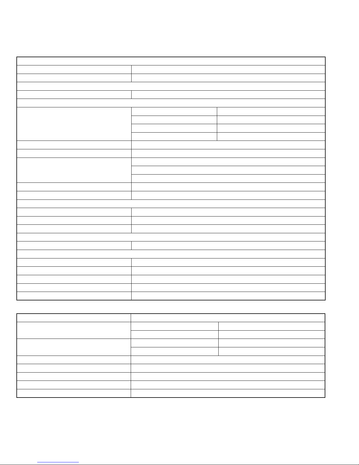
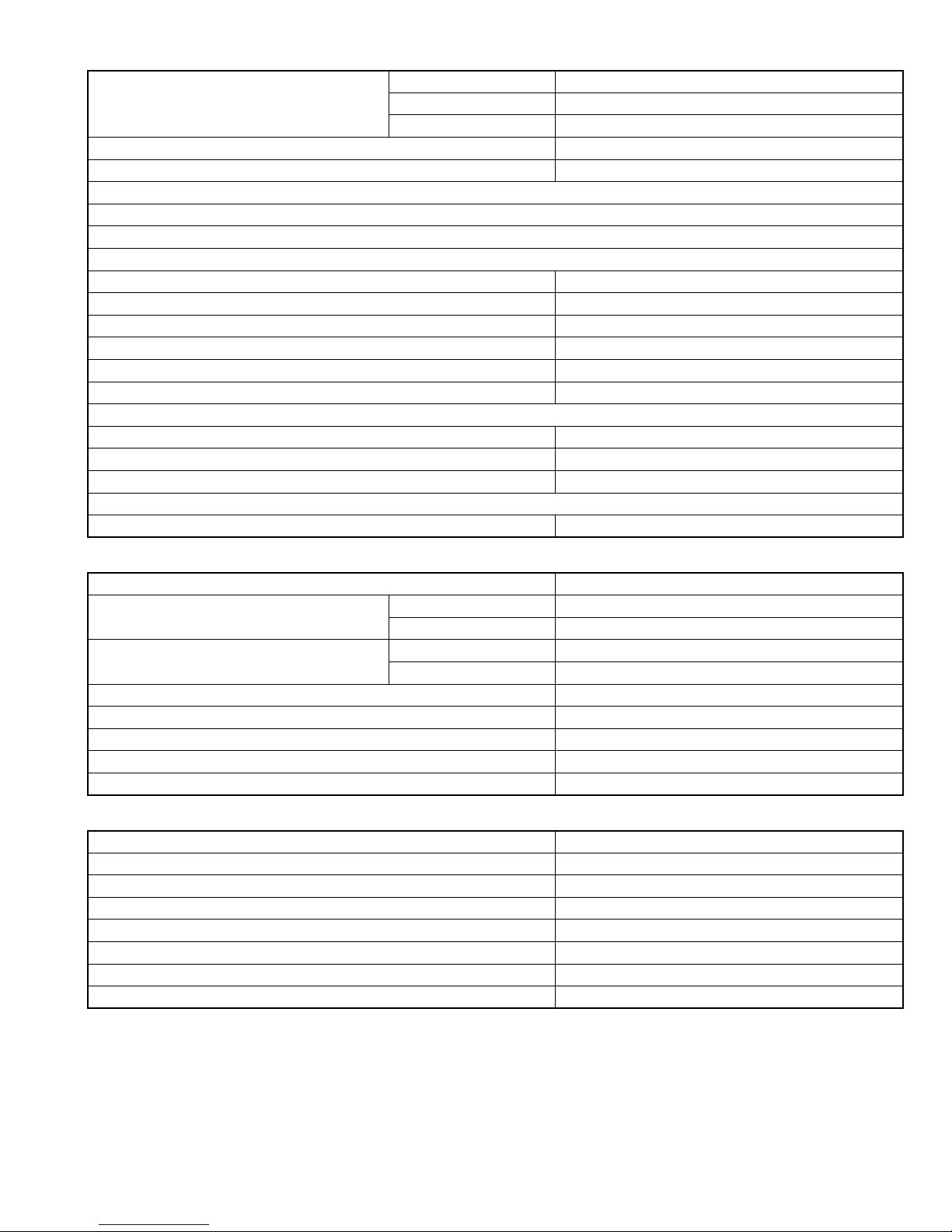
SPECIFICATION
For Europe
Main unit
Tuner
FM frequency 87.50 MHz - 108.00 MHz
AM frequency 522 kHz - 1 629 kHz
Terminal (front of the main unit)
Impedance 16 Ω - 1 kΩ
Terminal (rear of the main unit)
Left/right speakers Output power 200 W (50 W x 4) at 3 Ω (1 kHz/10 % THD)
Impedance 3 Ω - 16 Ω
Subwoofer Output power 150 W at 6 Ω 100 Hz/10 % THD)
Impedance 6 Ω - 16 Ω
Optical digital input terminal -23 dBm to -15 dBm
Optical digital output terminal -23 dBm to -15 dBm
Component video output terminals Y: 1.0 Vp-p, 75 Ω terminated
PB: 0.7 Vp-p, 75 Ω terminated
PR: 0.7 Vp-p, 75 Ω terminated
Composite video output terminal 1.0 Vp-p, 75 Ω terminated
Audio input terminals 500 mV/47 kΩ
USB(Compatible with USB 2.0 Full-Speed)
Compatible device USB mass storage class device
Compatible file system FAT16, FAT32
Output power DC 5 V = 500 mA
HDMI
Output power DC 5 V = 55 mA
General
Power source AC 230 V~50 Hz
Power consumption (in operation) 90 W
Power consumption (on standby) 0.8 W
Dimensions (W x H x D) [including projecting parts]
Mass 3.4 kg
300 mm x 95 mm x 295 mm
Speaker
Type 1-way bass reflex type Magnetically shielded type
Speaker driver Front ch 5.5 cm cone
Surround ch 5.5 cm cone
Power handling capacity Front ch 50W
Surround ch 50W
Impedance 3 Ω
Frequency range 80 Hz - 20 kHz
Sound pressure level 77 dB/W•m
Dimensions (W x H x D)[including projection parts]
Mass (1 speaker) 1.2 kg
1-2 (No.MB662<Rev.003>)
88 m x 184 mm x 125 mm
Page 3
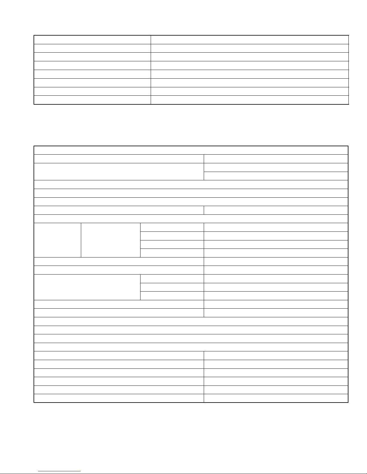
Subwoofer
Type Bass reflex type
Speaker driver 16 cm cone
Power handling capacity 150 W
Impedance 6 Ω
Frequency range 30 Hz - 200 Hz
Sound pressure level 76 dB/W•m
Dimensions (W x H x D) 300 mm x 301 mm x 305 mm
Mass 8.2 kg
Designs and specifications are subject to change without notice.
NX-F3A/UB
Main unit
Tuner
FM frequency 87.50 MHz - 108.00 MHz
AM frequency 531 kHz - 1 710 kHz (9 kHz spacing)
530 kHz - 1 710 kHz (10 kHz spacing)
Terminal (front of the main unit)
USB digital input terminal x 1
Audio output headphone terminal x 1
Impedance 16 Ω - 1 kΩ
Terminal (rear of the main unit)
Audio
output speaker
terminals x 1
Left/Right speakers Output power 200 W (50 W x 4) at 3 Ω (1 kHz/10 % THD)
Impedance 3 Ω - 16 Ω
Subwoofer Output power 150 W at 6 Ω (100 Hz/10 % THD)
Impedance 6 Ω - 16 Ω
Optical digital input terminal x 1 -23 dBm to -15 dBm
Optical digital output terminal x 1 -23 dBm to -15 dBm
Component video output terminals x 1 Y 1.0 Vp-p, 75 Ω terminated
PB 0.7 Vp-p, 75 Ω terminated
PR 0.7 Vp-p, 75 Ω terminated
Composite video output terminal x 1 1.0 Vp-p, 75 Ω terminated
Audio input terminals x 1 500 mV/47 kΩ
HDMI monitor output terminal x 1
FM antenna terminal x 1
AM antenna terminal x 1
General
Power source (Australia) AC 240 V~, 50 Hz
Power source (Hong Kong) AC 220 V~, 50 Hz
Power consumption (in operation) 90 W
Power consumption (on standby) 0.8 W
Dimensions (W x H x D) [including projecting parts] 300 mm x 95 mm x 295 mm
Mass 3.4 kg
(No.MB662<Rev.003>)1-3
Page 4
USB(Compatible with USB 2.0 Full-Speed)
Compatible device USB mass storage class device
Compatible file system FAT16, FAT32
Output power DC 5 V=500 mA
HDMI
Output power DC 5 V=55 mA
Speaker (SP-NXF3F)
Type 1-way bass reflex type Magnetically shielded type
Speaker driver Front ch 5.5 cm cone
Surround ch 5.5 cm cone
Power handling capacity Front ch 50W
Surround ch 50W
Impedance 3 Ω
Frequency range 80 Hz - 20 kHz
Sound pressure level 77 dB/W•m
Dimensions (W x H x D) [including projection parts] 88 mm x 184 mm x 125 mm
Mass (1 speaker) 1.2 kg
Subwoofer (SP-NXF3W)
Type Bass reflex type
Speaker driver 16 cm cone
Power handling capacity 150 W
Impedance 6 Ω
Frequency range 30 Hz - 200 Hz
Sound pressure level 76 dB/W•m
Dimensions (W x H x D) 300 mm x 301 mm x 305 mm
Mass 8.2 kg
Designs and specifications are subject to change without notice.
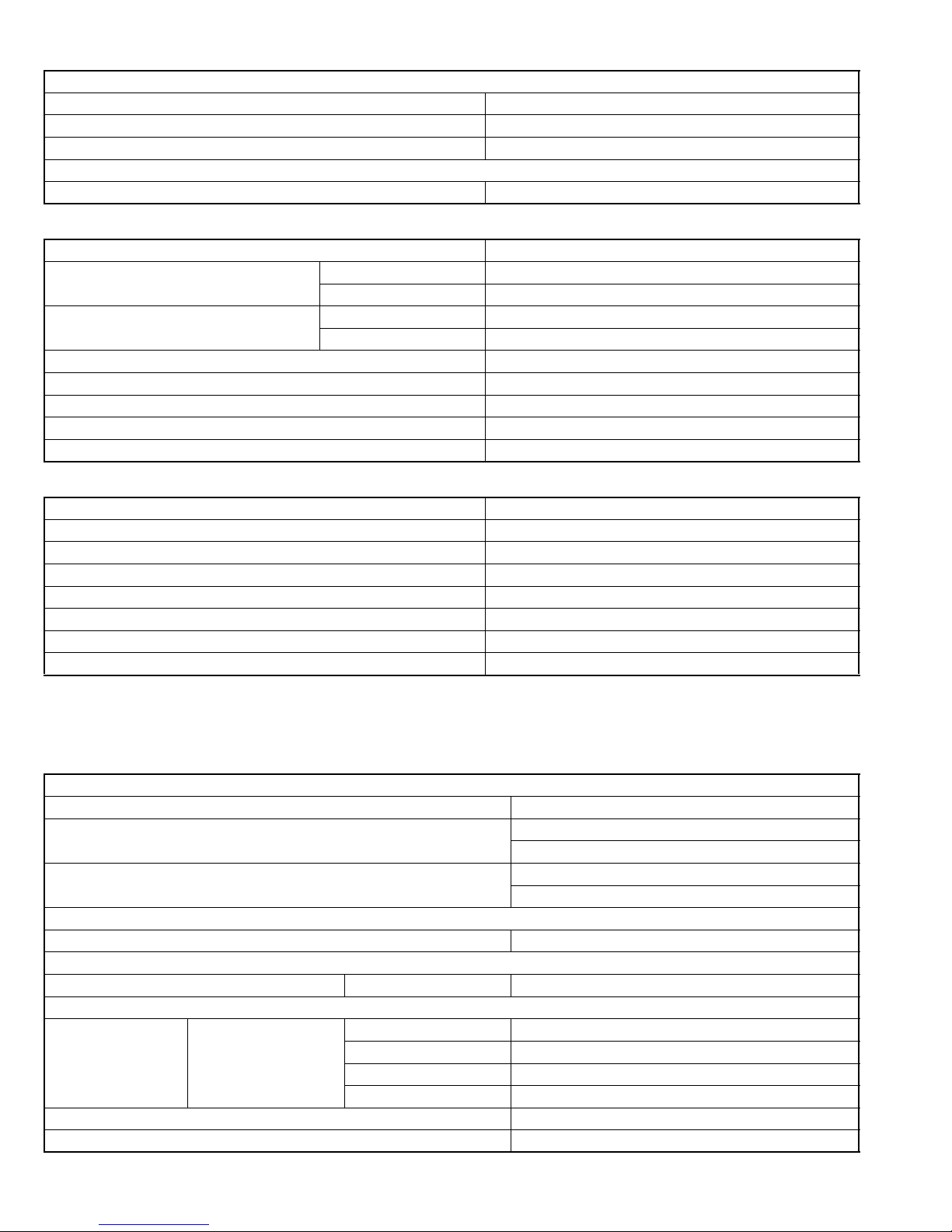
For asia
Main unit
Tuner
FM frequency 87.50 MHz - 108.00 MHz
AM frequency (Middle Eastern countries and South Africa) 531 kHz - 1 602 kHz (9 kHz spacing)
530 kHz - 1 600 kHz (10 kHz spacing)
AM frequency (other countries/areas) 531 kHz - 1 710 kHz (9 kHz spacing)
530 kHz - 1 710 kHz (10 kHz spacing)
Terminal (front of the main unit)
Microphone input terminal x 2 3.0 mV/12 kΩ
USB digital input terminal x 1
Audio output headphone terminal x 1 Impedance 16 Ω - 1 kΩ
Terminal (rear of the main unit)
Audio output speaker
terminals x 1
Left/Right speakers Output power 200 W (50 W x 4) at 3 Ω (1 kHz/10 % THD)
Impedance 3 Ω - 16 Ω
Subwoofer Output power 150 W at 6 Ω (100 Hz/10 % THD)
Impedance 6 Ω - 16 Ω
Optical digital input terminal x 1 -23 dBm to -15 dBm
Optical digital output terminal x 1 -23 dBm to -15 dBm
1-4 (No.MB662<Rev.003>)
Page 5
Component video output terminals x 1 Y 1.0 Vp-p, 75 Ω terminated
PB 0.7 Vp-p, 75 Ω terminated
PR 0.7 Vp-p, 75 Ω terminated
Composite video output terminal x 1 1.0 Vp-p, 75 Ω terminated
Audio input terminals x 1 500 mV/47 kΩ
HDMI monitor output terminal x 1
FM antenna terminal x 1
AM antenna terminal x 1
General
Power source (Thailand) AC 220 V~, 50 Hz
Power source (other countries/areas) AC 110 - 127/220 -240 V~,50/60 Hz
Power consumption (in operation) 90 W
Power consumption (on standby) 0.8 W
Dimensions (W x H x D) [including projecting parts] 300 mm x 95 mm x 295 mm
Mass 3.4 kg
USB (Compatible with USB 2.0 Full-Speed)
Compatible device USB mass storage class device
Compatible file system FAT16, FAT32
Output power DC 5 V=500 mA
HDMI
Output power DC 5 V=55 mA
Speaker (SP-NXF3F)
Type 1-way bass reflex type Magnetically shielded type
Speaker driver Front ch 5.5 cm cone
Surround ch 5.5 cm cone
Power handling capacity Front ch 50W
Surround ch 50W
Impedance 3 Ω
Frequency range 80 Hz - 20 kHz
Sound pressure level 77 dB/W•m
Dimensions (W x H x D) [including projection parts] 88 mm x 184 mm x 125 mm
Mass (1 speaker) 1.2 kg
Subwoofer (SP-NXF3W)
Type Bass reflex type
Speaker driver 16 cm cone
Power handling capacity 150 W
Impedance 6 Ω
Frequency range 30 Hz - 200 Hz
Sound pressure level 76 dB/W•m
Dimensions (W x H x D) 300 mm x 301 mm x 305 mm
Mass 8.2 kg
Designs and specifications are subject to change without notice.
(No.MB662<Rev.003>)1-5
Page 6

SECTION 1
PRECAUTION
1.1 Safety Precautions
(1) This design of this product contains special hardware and
many circuits and components specially for safety purposes. For continued protection, no changes should be made
to the original design unless authorized in writing by the
manufacturer. Replacement parts must be identical to
those used in the original circuits. Services should be performed by qualified personnel only.
(2) Alterations of the design or circuitry of the product should
not be made. Any design alterations of the product should
not be made. Any design alterations or additions will void
the manufacturers warranty and will further relieve the
manufacture of responsibility for personal injury or property
damage resulting therefrom.
(3) Many electrical and mechanical parts in the products have
special safety-related characteristics. These characteristics are often not evident from visual inspection nor can the
protection afforded by them necessarily be obtained by using replacement components rated for higher voltage, wattage, etc. Replacement parts which have these special
safety characteristics are identified in the Parts List of Service Manual. Electrical components having such features
are identified by shading on the schematics and by ( ) on
the Parts List in the Service Manual. The use of a substitute
replacement which does not have the same safety characteristics as the recommended replacement parts shown in
the Parts List of Service Manual may create shock, fire, or
other hazards.
(4) The leads in the products are routed and dressed with ties,
clamps, tubings, barriers and the like to be separated from
live parts, high temperature parts, moving parts and/or
sharp edges for the prevention of electric shock and fire
hazard. When service is required, the original lead routing
and dress should be observed, and it should be confirmed
that they have been returned to normal, after reassembling.
(5) Leakage shock hazard testing
After reassembling the product, always perform an isolation check on the exposed metal parts of the product (antenna terminals, knobs, metal cabinet, screw heads,
headphone jack, control shafts, etc.) to be sure the product
is safe to operate without danger of electrical shock.Do not
use a line isolation transformer during this check.
• Plug the AC line cord directly into the AC outlet. Using a
"Leakage Current Tester", measure the leakage current
from each exposed metal parts of the cabinet, particularly any exposed metal part having a return path to the
chassis, to a known good earth ground. Any leakage current must not exceed 0.5mA AC (r.m.s.).
• Alternate check method
Plug the AC line cord directly into the AC outlet. Use an
AC voltmeter having, 1,000Ω per volt or more sensitivity
in the following manner. Connect a 1,500Ω 10W resistor
paralleled by a 0.15µF AC-type capacitor between an ex-
posed metal part and a known good earth ground.
Measure the AC voltage across the resistor with the AC
voltmeter.
Move the resistor connection to each exposed metal
part, particularly any exposed metal part having a return
path to the chassis, and measure the AC voltage across
the resistor. Now, reverse the plug in the AC outlet and
repeat each measurement. Voltage measured any must
not exceed 0.75 V AC (r.m.s.). This corresponds to 0.5
mA AC (r.m.s.).
AC VOLTMETER
(Having 1000
ohms/volts,
or more sensitivity)
0.15 F AC TYPE
Place this
probe on
1500 10W
Good earth ground
1.2 Warning
(1) This equipment has been designed and manufactured to
meet international safety standards.
(2) It is the legal responsibility of the repairer to ensure that
these safety standards are maintained.
(3) Repairs must be made in accordance with the relevant
safety standards.
(4) It is essential that safety critical components are replaced
by approved parts.
(5) If mains voltage selector is provided, check setting for local
voltage.
1.3 Caution
Burrs formed during molding may be left over on some parts
of the chassis.
Therefore, pay attention to such burrs in the case of preforming repair of this system.
1.4 Critical parts for safety
In regard with component parts appearing on the silk-screen
printed side (parts side) of the PWB diagrams, the parts that are
printed over with black such as the resistor ( ), diode ( )
and ICP ( ) or identified by the " " mark nearby are critical
for safety. When replacing them, be sure to use the parts of the
same type and rating as specified by the manufacturer.
(This regulation dose not Except the J and C version)
each exposed
metal part.
1-6 (No.MB662<Rev.003>)
Page 7
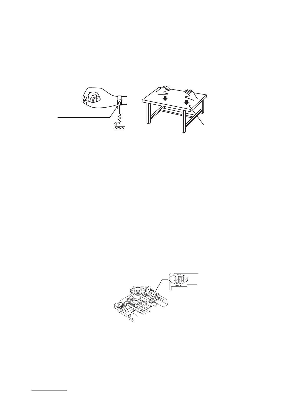
1.5 Preventing static electricity
Electrostatic discharge (ESD), which occurs when static electricity stored in the body, fabric, etc. is discharged, can destroy the laser
diode in the traverse unit (optical pickup). Take care to prevent this when performing repairs.
1.5.1 Grounding to prevent damage by static electricity
Static electricity in the work area can destroy the optical pickup (laser diode) in devices such as laser products.
Be careful to use proper grounding in the area where repairs are being performed.
(1) Ground the workbench
Ground the workbench by laying conductive material (such as a conductive sheet) or an iron plate over it before placing the
traverse unit (optical pickup) on it.
(2) Ground yourself
Use an anti-static wrist strap to release any static electricity built up in your body.
(caption)
Anti-static wrist strap
1M
Conductive material
(conductive sheet) or iron palate
(3) Handling the optical pickup
• In order to maintain quality during transport and before installation, both sides of the laser diode on the replacement optical
pickup are shorted. After replacement, return the shorted parts to their original condition.
(Refer to the text.)
• Do not use a tester to check the condition of the laser diode in the optical pickup. The tester's internal power source can easily
destroy the laser diode.
1.6 Handling the traverse unit (optical pickup)
(1) Do not subject the traverse unit (optical pickup) to strong shocks, as it is a sensitive, complex unit.
(2) Cut off the shorted part of the flexible cable using nippers, etc. after replacing the optical pickup. For specific details, refer to the
replacement procedure in the text. Remove the anti-static pin when replacing the traverse unit. Be careful not to take too long a
time when attaching it to the connector.
(3) Handle the flexible cable carefully as it may break when subjected to strong force.
(4) I t is not possible to adjust the semi-fixed resistor that adjusts the laser power. Do not turn it.
1.7 Attention when traverse unit is decomposed
*Please refer to "Disassembly method" in the text for the pickup unit.
• Apply solder to the short land sections before the card wire is disconnected from the connecto on the servo board. (If the card wire
is disconnected without applying solder, the pickup may be destroyed by static electricity.)
• In the assembly, be sure to remove solder from the short land sections after connecting the card wire.
Solder short land section
(No.MB662<Rev.003>)1-7
Page 8
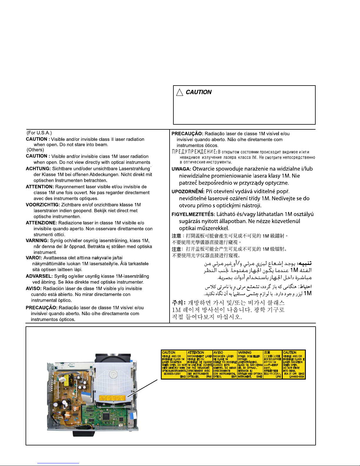
1.8 Important for laser products
1.CLASS 1 LASER PRODUCT
2.CAUTION :
(For U.S.A.) Visible and/or invisible class II laser radiation
when open. Do not stare into beam.
(Others) Visible and/or invisible class 1M laser radiation
when open. Do not view directly with optical instruments.
3.CAUTION : Visible and/or invisible laser radiation when
open and inter lock failed or defeated. Avoid direct
exposure to beam.
4.CAUTION : This laser product uses visible and/or invisible
laser radiation and is equipped with safety switches which
prevent emission of radiation when the drawer is open and
the safety interlocks have failed or are defeated. It is
dangerous to defeat the safety switches.
5.CAUTION : If safety switches malfunction, the laser is able
to function.
6.CAUTION : Use of controls, adjustments or performance of
procedures other than those specified here in may result in
hazardous radiation exposure.
!
Please use enough caution not to
see the beam directly or touch it
in case of an adjustment or operation
check.
REPRODUCTION AND POSITION OF LABELS and PRINT
WARNING LABEL and PRINT
1-8 (No.MB662<Rev.003>)
Page 9

SECTION 2
SPECIFIC SERVICE INSTRUCTIONS
This service manual does not describe SPECIFIC SERVICE INSTRUCTIONS.
(No.MB662<Rev.003>)1-9
Page 10
SECTION 3
DISASSEMBLY
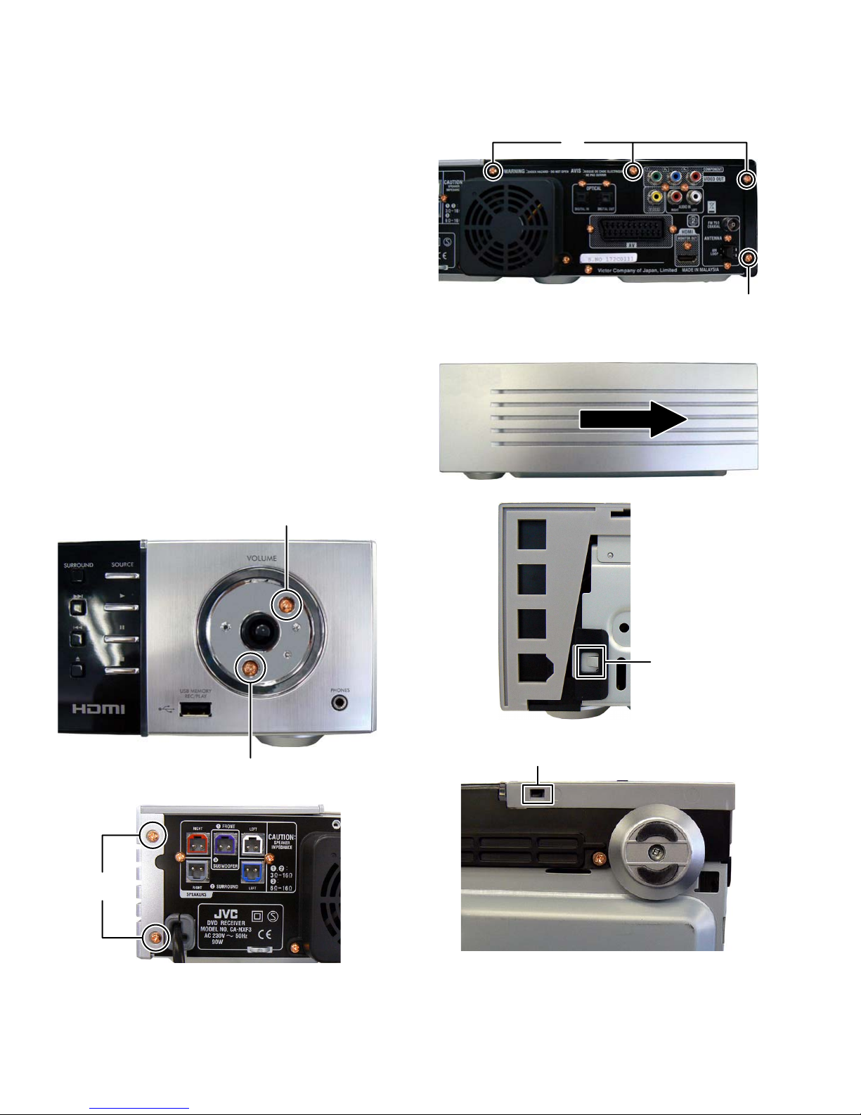
3.1 Main body (Used figure are NX-F3E)
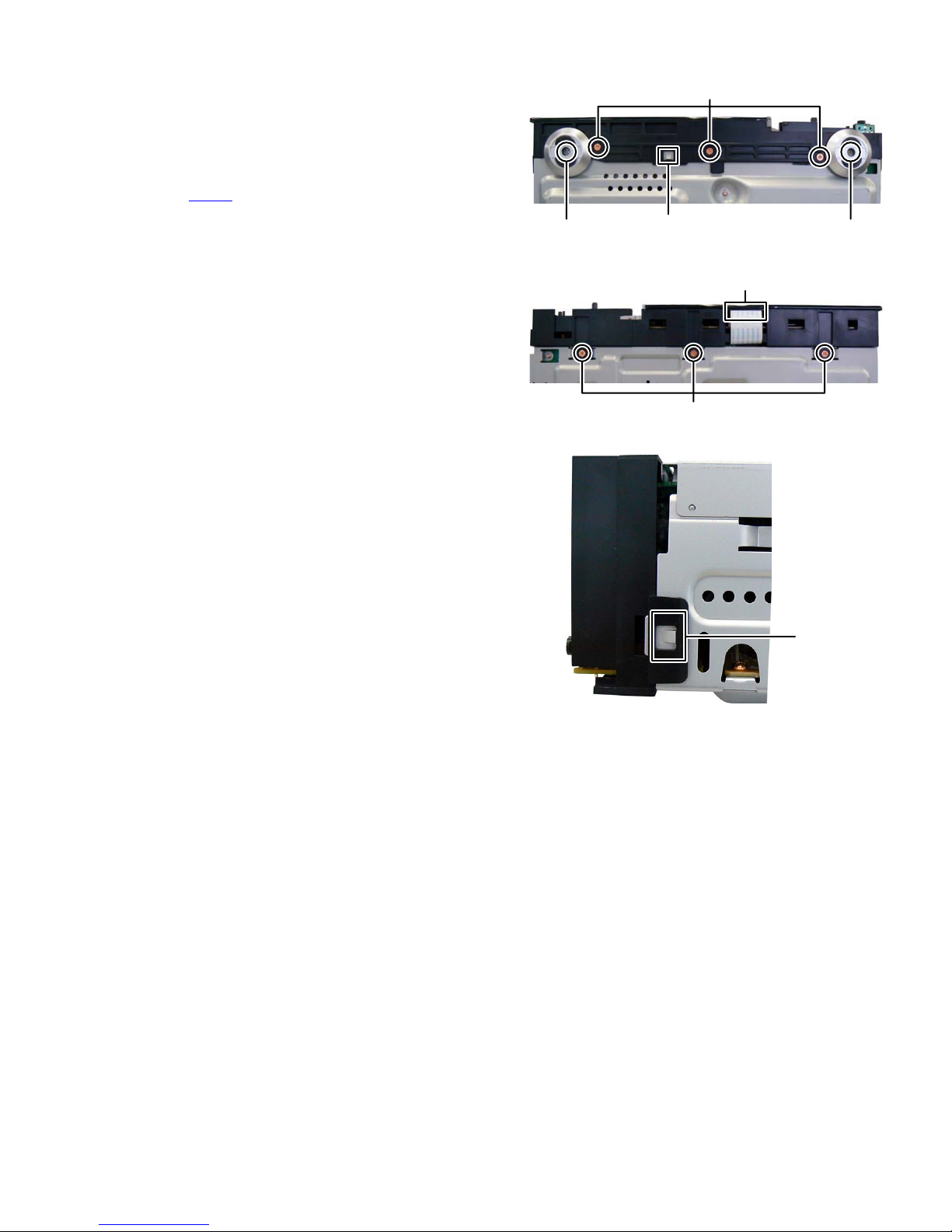
3.1.1 Removing the Top panel (L) (See Fig.1)
(1) Remove the four screws A attaching the Top panel (L).
(2) Slide to backward and then lift up side of the Top panel (L).
3.1.2 Removing the Top panel (R) (See Fig.2 to 6)
(1) Remove the Volume knob and Volume sheet.
(2) Remove the two screws B attaching the Volume ornament.
(See Fig.2)
(3) Remove the two screws C attaching the Side panel. (See
Fig.3)
(4) Slide to backward and then remove the Side panel. (See
Fig.4)
(5) Disengage one hook a and one hook b engaged Top panel
(R). (See Fig.5. 6)
A
A
Fig.1
Fig.4
C
Fig.2
B
B
hook b
Fig.5
hook
a
Fig.3
1-10 (No.MB662<Rev.003>)
Fig.6
Page 11
3.1.3 Removing the Front panel (See Fig.7 to 9)
(1) Remove the two screws D attaching the Foot. (See Fig.7)
(2) Remove the three screws E attaching the Front panel. (See
Fig.7)
(3) Remove the three screws F attaching the Front panel. (See
Fig.8)
(4) Disconnect the card wire from Micon board connected to
connector CN561
(5) Disengage one hook c of the bottom side of Front panel
and two hooks d engaged both side of Front panel. (See
Fig.7, 9)
of the Front board. (See Fig.8)
D
hook
c
Fig.7
F
Fig.8
E
D
CN561
Fig.9
hook
d
(No.MB662<Rev.003>)1-11
Page 12
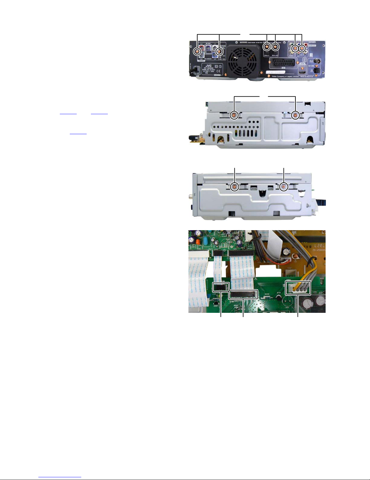
3.1.4 Removing the Top chassis (See Fig.10 to 13)
(1) Remove the six screws G attaching the Rear panel. (See
Fig.10)
(2) Remove the two screws H attaching the right side of Top
chassis. (See Fig.11)
(3) Remove the one screw J and one screw K attaching the left
side of Top chassis. (See Fig.12)
CAUTION:When remove the screw K, use screw driver is next.
TORX Driver: size T10
Parts number: DR-L70
(4) Slide to frontward, and then turnover the Top chassis.
(5) Disconnect the card wires from Micon board connected to
connectors CN101
Fig.13)
(6) Disconnect the connector wire from Power board connect-
ed to connector CN103
and CN102 of the Amp board. (See
of the Amp board. (See Fig.13)
G
Fig.10
H
Fig.11
JK
Fig.12
CN101 CN102 CN103
Fig.13
1-12 (No.MB662<Rev.003>)
Page 13
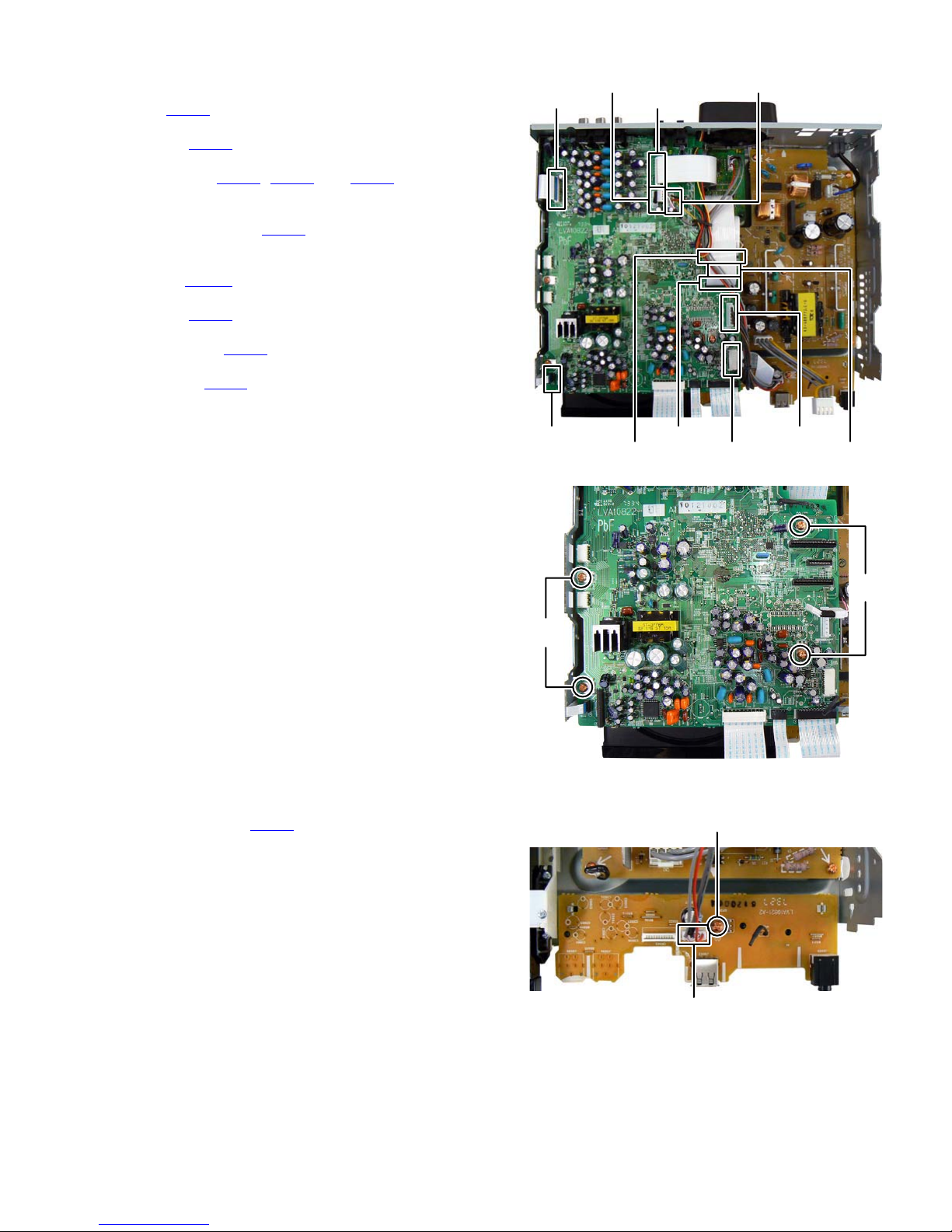
3.1.5 Removing the Micon board (See Fig.14 to15)
(1) Disconnect the connector wire from Fan connected to con-
nector CN461
(2) Disconnect the card wire from SCART board connected to
connector CN601
(3) Disconnect the card wires from Front end board connected
to connectors CN701, CN481 and CN661 of the Micon
board. (See Fig.14)
(4) Disconnect the connector wire from Front end board con-
nected to connector CN702
Fig.14)
(5) Disconnect the card wire from Tuner pack connected to
connector CN421
(6) Disconnect the card wire from Loader board connected to
connector CN451
(7) Disconnect the connector wire from power board connect-
ed to connector CN981
(8) Disconnect the card wire from USB jack board connected
to connector CN203 of the Micon board. (See Fig.14)
(9) Remove the four screws L attaching the Micon board. (See
Fig.15)
of the Micon board. (See Fig.14)
of the Micon board. (See Fig.14)
of the Micon board. (See
of the Micon board. (See Fig.14)
of the Micon board (See Fig.14)
of the Micon board. (See Fig.14)
CN421
CN451
CN702
CN661
CN601
CN701
CN461
CN981
CN203 CN481
Fig.14
3.1.6 Removing the USB jack board (See Fig.16)
(1) Disconnect the connector wire from Front end board con-
nected to connector CN301
(2) Remove the one screw M attaching the USB jack board.
(3) Lift up the right side, and then slide to leftward and remove
the USB jack board.
of the USB jack board.
L
L
Fig.15
M
CN301
Fig.16
(No.MB662<Rev.003>)1-13
Page 14
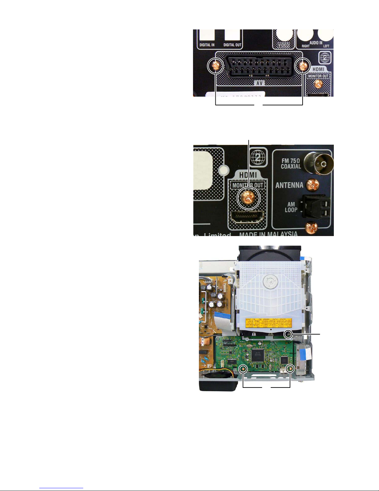
3.1.7 Removing the SCART board (See Fig.17)
(1) Remove the two screws N attaching the SCART board.
3.1.8 Removing the DVD mechanism (See Fig.18, 19)
(1) Remove the one screw P attaching the HDMI jack. (See
Fig.18)
(2) Remove the two screws Q attaching the Front end board.
(See Fig.19)
(3) Remove the one screw R attaching the DVD mechanism.
(See Fig.19)
N
Fig.17
P
Fig.18
Q
Fig.19
R
1-14 (No.MB662<Rev.003>)
Page 15
3.1.9 Removing the Rear panel (See Fig.20)
(1) Remove the two screws S attaching the Rear panel.
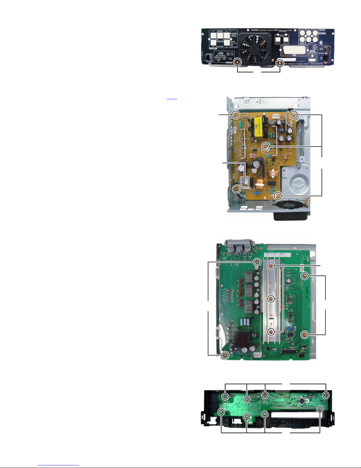
3.1.10 Removing the Power board (See Fig.21)
(1) Disconnect the power cord connected to connector CN1
the Power board.
(2) Remove the five screws T attaching the Power board.
S
Fig.20
of
T
3.1.11 Removing the Amp board (See Fig.22)
(1) Remove the two screws U attaching the Barrier.
(2) Remove the three screws V attaching the Heat sink.
(3) Remove the two screws W attaching the Amp board.
U
CN1
T
T
Fig.21
V
W
3.1.12 Removing the Front board (See Fig.23)
(1) Remove the eight screws X attaching the Front board.
Fig.22
X
X
Fig.23
(No.MB662<Rev.003>)1-15
Page 16
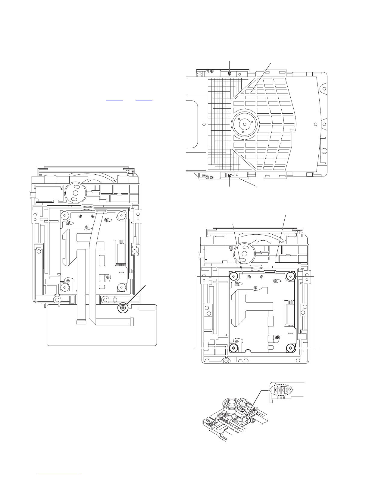
3.2 DVD mechanism
3.2.1 Removing the traverse mechanism
(See Fig.1 to 4)
(1) Remove the one screw A attaching the Front end board.
(See Fig.1)
(2) Remove the two screws B attaching the tramecha holder
from top side of DVD mechanism assembly. (See Fig.2)
(3) Remove the four screws C attaching the traverse mecha-
nism. (See Fig.3)
(4) Solder the solder part of DVD pick up. (See Fig.4)
(5) Disconnect the card wire from CN101
DVD module board. (See Fig. 1)
Caution:
• Solder the short land section on the DVD pickup before dis-
connecting the card wire from the connector on the DVD
pickup. If the card wire is disconnected without attaching solders, the pickup may be destroyed by static electricity.
• When attaching the DVD pickup, be sure to remove solders
from the short land section after connecting the card wire to
the connector on the DVD pickup.
and CN201 on the
B
Clamper base
CN101
Fig.1
CN201
A
B
Traverse mechanism assembly
DVD mechanism assembly
Fig.2
DVD mechanism assembly
CC
1-16 (No.MB662<Rev.003>)
Fig.3
Solder short land section
Fig.4
Page 17
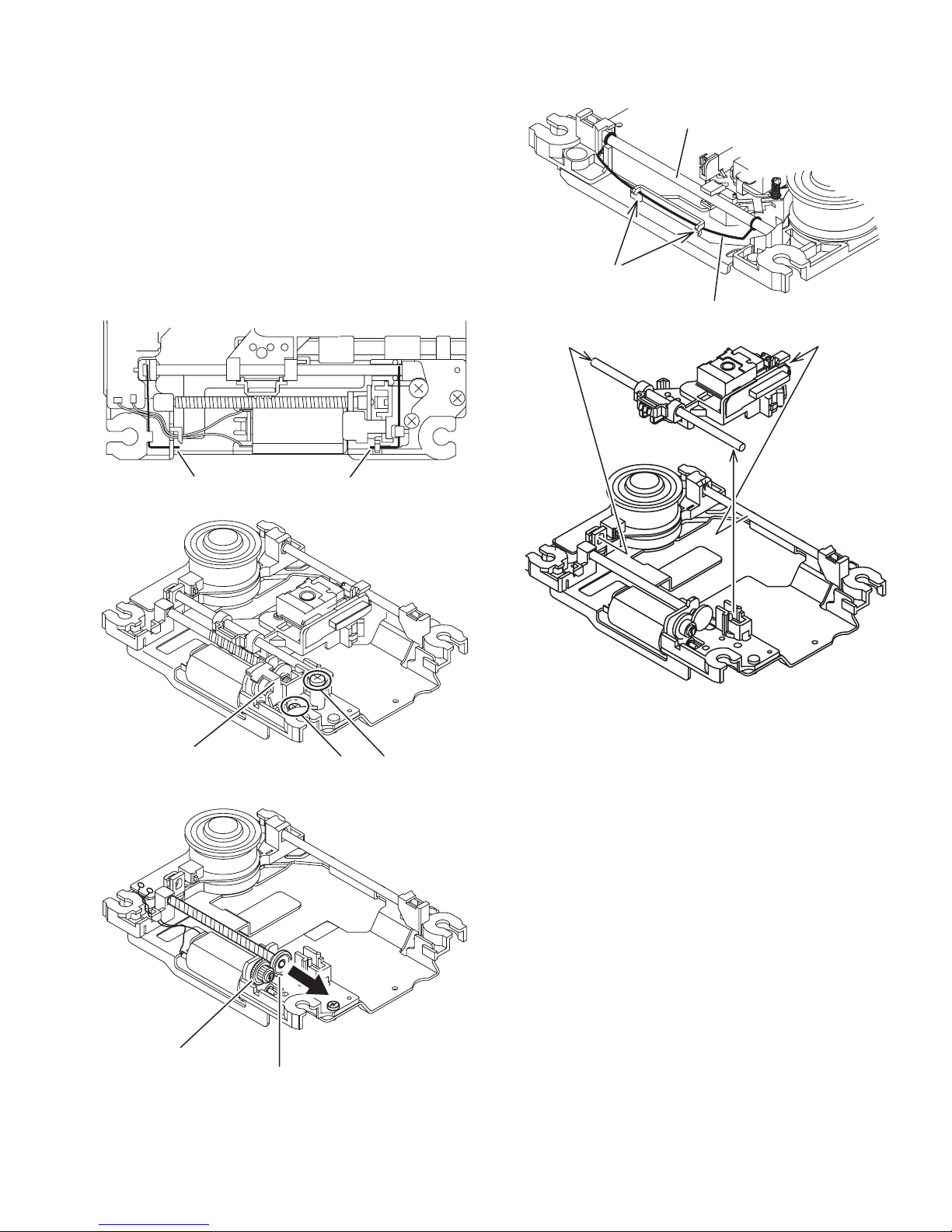
3.2.2 Removing the pickup assembly
(See Fig.5 to 9)
(1) Remove the two rod springs pressing the guide shaft. (See
Fig.5)
(2) Remove the screw D and E attaching the spring holder.
(See Fig.6)
(3) Remove the read screw from traverse mechanism assem-
bly. (See Fig.7)
Caution:
When remove the lead screw, do not loss the middle
gear. (See Fig.8 and 9)
(4) Remove the bar spring pressing the shaft. (See Fig.8)
(5) Take out the pickup assembly from traverse mechanism
chassis by order. (See Fig.9)
(SHAFT)
(T.TABLE)
HOOK
(BAR SPRING)
Fig.8
ROD SPRING ROD SPRING
Fig.5
Spring holder
Fig.6
order 2
order 3
order 1
Fig.9
DE
Middle gear
Lead screw
Fig.7
(No.MB662<Rev.003>)1-17
Page 18
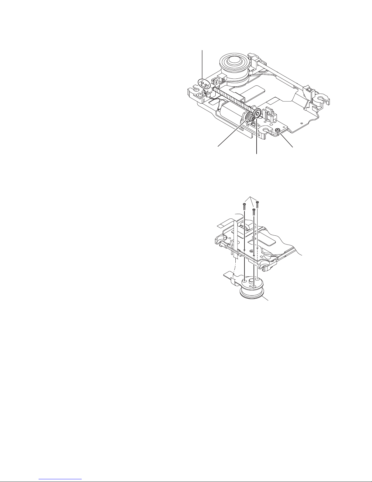
3.2.3 Removing the feed motor assembly
(See Fig.10)
(1) Remove the one screw F attaching the feed motor assem-
bly.
(2) Remove the feed motor wires from solder part of spindle
motor board.
Solder part
3.2.4 Removing the spindle motor assembly
(See Fig.11)
(1) Remove the three screws G attaching the spindle motor
from spindle motor board.
Middle gear
Lead screw
Fig.10
G
Spindle motor
Fig.11
F
1-18 (No.MB662<Rev.003>)
Page 19
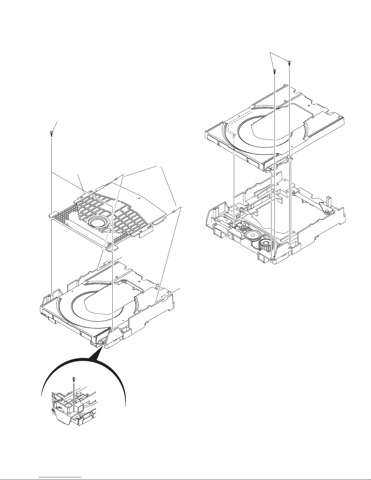
3.2.5 Removing the tray assembly
(See Fig.12 & 13)
(1) Remove the two screws H attaching the clamper base.
(See Fig.12)
(2) Remove the one screw J attaching the shaft guide from
bottom side. (See Fig.12)
(3) Remove the two screws K attaching the shaft guide from
top side. (See Fig.13)
Caution:
When attach the tray assembly, boss of loading sub assembly
should attach to guide of bottom side at tray assembly. (See
Fig.13)
H
order 1
order 2
clamper base
K
J
Fig.13
[bottom side]
Fig.12
(No.MB662<Rev.003>)1-19
Page 20

SECTION 4
ADJUSTMENT
4.1 ATTENTION IN SERVICE OF DVD SECTION
(1) When pickup, Flash ROM ,DVD module board were changed, initialize EEPROM by all means.
(2) When full initialization was executed, execute learning with a DVD test disc by all means.
Test disc : VT-501, VT-502
Learning method : It is adjusted automatically by normal playback of a DVD disc.
4.2 DVD TEST MODE
4.2.1 Content of correspondence TEST MODE
(1) Version, Region, Learning status check mode
(2) NORMAL initialize, FULL initialize
(3) Device key write(CPPM, CPRM)
(4) Device key checksum indication mode
(5) Micon version indication mode
(6) FL all on mode
(7) FRONT END check mode
4.2.2 Mode transition
TEST MODE into the press [OPEN/CLOSE key] and [PLAY key] together of main body, connect the AC power.
After into the TEST MODE, mode select by [MENU key].
OPEN/CLOSE+PLAY+AC
Version, Region, Learning
status indication mode
MENU key
Device key
checksum
MENU key MENU key MENU key
Micon version
indication mode
FL all on
mode
FRONT END
check mode
mode
SOURCE key
F.SKIP key 4seclong press
B.SKIP
NORMAL
initialize
FULL
initialize
Device key
write
MENU key
MENU key
4.2.3 Processing details
The communication of operated FL(LCD) display and DVD back end microcomputer is shown as follows.
*It is assumed to be OK to differ from the content of the specification because the number of digits is different according to the set for the FL(LCD) display.
It is assumed to be OK to differ from the content of the specification because it also has the relation between arrangement and presence by the set also for the key.
STEP Operation Movement Remarks
1
AC is pulled out, and
double press
[OPNE/CLOSE] and
[PLAY] key of the main
body
2 Keep step 1, connect AC
Version, Region, Learning
status indication mode
Power on by test mode,
version indication to FL
FL(LCD)indication
132465798
T
JC#
10 1211 13
Version indication
The display to the version code is as
follows.
0x01:JC 0x02:1U 0x03:D 0x04:E
0x05:2U 0x06:3U 0x07:UB 0x08:UT
0x09:4U 0x0a:UY 0x0b:EE 0x0c:UF
Region indication (# part)
Learning from the back end is displayed
in the 11th digit and the 12th digit
of the FL display.
Blank indication at 0xFF
Study status (11th column)
0x07: BCA CHECK OK incomplete
DVD learning incomplete
CD learning incomplete (indication 7)
0x06: BCA CHECK OK incomplete
DVD learning complete
CD learning incomplete (indication 6)
0x05: BCA CHECK OK incomplete
DVD learning incomplete
CD learning complete (indication 5)
1-20 (No.MB662<Rev.003>)
Page 21
STEP Operation Movement Remarks
132465798
FL(LCD)indication
10 1211 13
0x04: BCA CHECK OK incomplete
DVD learning complete
CD leaning complete (indication 4)
0x03: BCA CHECK OK complete
DVD learning incomplete
CD learning incomplete (indication 3)
0x02: BCA CHECK OK complete
DVD learning complete
CD learning incomplete (indication 2)
0x01: BCA CHECK OK complete
DVD learning incomplete
CD learning complete (indication 1)
0x00: BCA CHECK OK complete
DVD learning complete
CD learning complete (indication 0)
(BCA READ CHECK result is only BCA
READ OK, it to complete)
Initialization status (12th column)
0X03: FULL initialize complete
(indication 3)
0x00: NORMAL initialize complete
(indication 0)
0xFF: Initialize incomplete
(blank indication)
Press a [SOURCE] key
of the main body.
NORMAL initialize
Continue pressing a
[F.SKIP] key of the main
body.(4sec)
FULL initialize
3
Press a [MENU] key of
the remote controller.
Press a [MENU] key of
the remote controller.
4 Press a [MENU] key of
the remote controller.
Press a [MENU] key of
5 FL all on mode
the remote controller.
Press a [MENU] key of
6
the remote controller.
Press a [1] key of the
remote controller
Press a [2] key of the
remote controller
Press a [3] key of the
remote controller
DEVICE CHECKSUM
indication mode
Indicate the CHECKSUM
of the Device key to FL
(4 byte)
Micon version indication
mode
Indicate the version to FL
All FL and all LED to ON
FRONT END check mode
Indicate the front end check
mode to FL
Disc startup and through
playback
(Playback starts from the
start position)
Presence of WOBBLE
0:WOBBLE_NO_CHECK
(un check)
1:WOBBLE_PRESS_MEDIA
(press)
2:WOBBLE_MINUS_MEDIA
(DVD-R/-RW media)
3:WOBBLE_PLUS_MEDIA
(DVD+R/+RW media)
Port check mode
(TRACK,INDEX,DEMP,
COPY)
1:INDEX Port = High
2:TRACK Port = High
3:COPY Port = High
4:DEMP Port = High
JC#T
JC#
T
bbcccac
CEHCK
CEHCK
The AVC protocol is returned from
high speed to normal speed.
(Return it to the normal mode when
coming off the TEST mode. )
Indicate CHECKSUM to FL
,,,
,,,
,,,
bb : Syscon Version
a : Syscon Romcorr Version
cccc: DVD Back end Version
Upper : 0
Lower : WOBBLE detection result
Upper : 0x01-0x04(check port number)
Lower : 0
: CPPM
: CPRM
: HDCP
(No.MB662<Rev.003>)1-21
Page 22
STEP Operation Movement Remarks
Press a [4] key of the
remote controller
Press a [5] key of the
remote controller
Press a [6] key of the
remote controller
Press a [8] key of the
remote controller
Press a [9] key of the
emote controller
Press a [10] key of the
remote controller
Press a [0] key of the
remote controller
Press a [ 10] key of the
remote controller
Press a [STOP] key of
the main body or remote
controller
Press a [OPEN/CLOSE]
key of the main body or
remote controller
Press a [PLAY] key of
the main body or remote
controller
Press a [MENU] key of
7
the remote controller
Press a [POWER] key of
the main body
CD_LD lights and laser
current is displayed
DVD_LD lights and laser
current is displayed
DVD_SL x1 jitter
measurement mode
Content of BACKUP
memory(0x00-0x63)
indication (FWD)
Temperature sensor
(AD value) indication
DVD-DL(parallel,opposite)
Search & jitter
measurement of the
specified position of
DVD-SL
MONITOR output switch
1: SRV_MONI_CIRC
2: SRV_MONI_SERVO
3-5: SRV_MONI
_ANALOG
6-7: SRV_MONI_DRC
8-11: SRV_MONI
_SERVO_JIG
12: SRV_MONI
_DEFAULT
BCA READ CHECK
0:During BCA READ
1:BCA READ OK
2:BCA SEEK ERROR
3:BCA READ ERROR
4:SPINUP adjust ERROR
Disc stop, LD-OFF
Tray Open/Close
Disc playback
Back to STEP 2
Release the TEST MODE
132465798
FL(LCD)indication
10 1211 13
Upper : Laser current value
(BACKUP value,Real measured value)
Lower : 0
Upper : Laser current value
(BACKUP value,Real measured value)
Lower : 0
Upper : Laser current value
(BACKUP value,Real measured value)
Lower : Real measured value
Upper Byte1 : Display option
0x00 : BACKUP area
0xFF : permanent area
Upper Byte2 : BACKUP memory address
(0x00-0x63)
Lower : Content of BACKUP memory
Upper : 0
Lower : Temperature sensor value
Upper : 0x00-0x06(measure at VT501)
Lower : Jitter value
Upper : 0x00-0x0C
Lower : 0
CEHCK
Upper:Laser current value
(BACKUP value, Real measured value)
Lower:Jitter value
Release at each step
*1 Mode toggle done by press [MENU] key.
*2 STEP3 are only for DVD-AUDIO or VR correspondence model.
1-22 (No.MB662<Rev.003>)
Page 23
4.3 KEY special mode
MODE NAME OPERATIONSTATUS FUNCTION
TUNER 9K/10kHz
select (U ver)
TRAY LOCK
DVD TEST mode
FL & LED all on
STANDBY
P. O F F
AC off
P. O N
mode
4.4 REMOCON KEY special mode
Change to 9kHz step by
press and hold [|<<] key,
then press [POWER] key.
Change to 10kHz step by
press and hold [>>|] key,
then press [POWER] key.
Press and hold [STOP]
key, then press
[OPEN/CLOSE] key, and
keep 1sec. more.
Press and hold
[
OPEN/CLOSE
] and [
PLAY
key, and connect to AC.
Press and hold [STOP]
key, and press [POWER]
key 5sec. more.
Main body to power to ON,
TUNER AM 9kHz/10kHz step select.
Indicate "9k STEP", "10k STEP".
Do the TRAY LOCK mode select. Done the temporary
P.ON process, select the "LOCKED" and "UNLOCKED"
(Do no done the P.ON process).
Ended the transitory display (2 seconds) return to
P.OFF mode.
When press the [EJECT] key at LOCK mode, at P.OFF
status do templary P.ON process then the transitory display
(2 seconds) the "LOCKED", at P.ON status do the transitory
display (2 seconds) the "LOCKED".
DVD back end started by TEST mode.
Internal TEST mode process is refer the spec.
]
Into the TEST MODE.
FL and LED all to ON.
Normal indication by any key.
MODE NAME OPERATIONCODE FUNCTION
COLD START
[STOP] +
[POWER] + [0]
2 times input at P.OFF
When Fix by 2 times input, do the templary P.ON
process then indicate "COLD SET" by transitory
a(2 seconds).
Ended the indication, change to P.OFF mode.
SYSTEM TEST MODE
FL all ON
Write the preset frequency
FAN high speed
[STOP] +
[POWER] + [1]
Input at P.ON
Write the preset frequency, LED all on check
(each 300ms), FL all on, LED on
(order : STANDBY -> ILLUMI -> K2), FAN high speed
(clear by STANDBY)
Volume control by [VOL+] and [VOL-] key of the
remote controller, it should high speed mode until
next POWER OFF.
DVD STATUS MODE
[STOP] +
[POWER] + [2]
Input at P.ON
At every [STOP] + [POWER] + [2] input, it display a
DVD status.
NORMAL indication
=> DVD temp status
=> EDID status
=> Normal indication from come out the mode
SYSTEM STATUS MODE
[STOP] +
[POWER] + [3]
Input at
P.ON/STANDBY
At every [STOP] + [POWER] + [3] input, it display a
variable / the terminal voltage of the following syscom
Normal indication
=> Indicate last shut down status
=> Indication temperature detection
(power supply block, amp block), A/D port voltage
=> Indicate Sound level (LVL_DET) A/D poet voltage
volume att value of volume IC
=> Normal indication from come out the mode
SPK OUTPUT MEASURE
MODE
[STOP] +
[POWER] + [4]
Input at
P.ON/STANDBY
Shift to speaker output measurement by input
[STOP] + [POWER] + [4]
Indicate "MEASURE", it cancel VOLUME ATT
restrictions processing by the sound level detection.
[STOP] + [POWER] + [4]
Version indication
[STOP] +
[POWER] + [10]
Input at P.ON
Come out the mode by input
Indicate syscom back end software at each input
[STOP] + [POWER] + [10]
NORMAL indication
=> syscom ROM version
=> syscom model/destination
=> Back end Firm Version
=> Back end destination/REGION
=> Normal indication from come out the mode
(No.MB662<Rev.003>)1-23
Page 24

4.5 SPECIAL MODE
4.5.1 DVD STATUS MODE
It perform the following indication state transition, when receive the [POWER] + [STOP] + [2] at POWER ON status.
Come out by any key.
POWER ON status
1 DVD temp info indication
2 EDID information indication
Normal indication
4.5.2 SYSTEM STATUS MODE
It perform the following indication state transition, when receive the [POWER] + [STOP] + [3] at POWER ON status.
Come out by any key.
<POWER ON STATUS>
POWER ON status
1 Indication of a Shutdown cause
2 Indication of the AD port PWR_THERMO: AMP_THERMO: LVL_DET voltage
3 Indication of VOLUME Gain restrictions value.
Effectiveness Gain restrictions value
Gain restrictions value by the temperature
Gain restrictions value by the sound
Normal indication
Attention in use: Because various SAFETY detection processing starts from POWER ON 2 sec. later, shift to
TEST MODE from POWER ON for less than 2 sec. when it want to let you display a
Shutdown cause.
4.5.3 SPK OUTPUT MEASURE MODE
It shift to the SPK OUTPUT MEASUREMENT MODE, when receive the [POWER] + [STOP] + [4] at POWER ON status.
Normal indicate "MEASURE" to FL, it cancel VOLUME ATT restrictions processing by the sound level detection.
Come out by input again [POWER] + [STOP] + [4].
This power measurement mode is for production line.
POWER ON status
SPK OUTPUT MEASURE MODE
Come out mode
4.5.4 VERSION INDICATION
It perform the following indication state transition, when receive the [POWER] + [STOP] + [10] at POWER ON status.
Come out by any key.
POWER ON status
1 Indication of the syscom ROM ver.
2 Indication of the syscom Model/Destination
3 Indication of the Back end firm ver.
4 Indication of the Back end Destination/Region
NORMAL indication
1-24 (No.MB662<Rev.003>)
Page 25

4.6 OTHER FUNCTION
4.6.1 SUMMARY
It memorize why it was performed between things of STANDBY by POWER ON of the last and receive TEST MODE
[POWER] + [STOP] + [3] and plan improvement of the hardware examination efficiency in what I display.
4.6.2 MEMORY AND INDICATION
The memory of the SAFETY item which IT detected assumes it a chisel for once of the last.
It dose not have it as a history.
The memory assumes it STANDBY memory / INH memory.
SYSTEM STATUS MODE
FL indication
S D. : @ @ :
COLD SET (initial value)
POWER key of remote controller
POWER key of main body
SLEEP TIMER
STANDBY request by CEC
At SAFETY
SAFETY ERROR number
Not SAFETY ERROR (Normal)
Value of SAFETY ERROR port (AD)
* *
Value of SAFETY ERROR port (STATIC)
Not SAFETY ERROR (Normal)
= 0
*
= 2
*
= 3
*
= 5
*
= 8
*
-
=
*
= port number
--
=
* * = AD value
* * = H or L
--
* * =
SECTION 5
TROUBLESHOOTING
This service manual does not describe TROUBLESHOOTING.
(No.MB662<Rev.003>)1-25
Page 26

Victor Company of Japan, Limited
Audio/Video Systems Division 10-1,1chome,Ohwatari-machi,Maebashi-city,371-8543,Japan
(No.MB662<Rev.003>)
Printed in Japan
VPT
Page 27

SCHEMATIC DIAGRAMS
COMPACT COMPONENT SYSTEM
NX-F3B,NX-F3E, NX-F3EN,NX-F3EV
NX-F3A,NX-F3EE,NX-F3US,NX-F3UB
NX-F3UW,NX-F3UX,NX-F3UG,NX-F3UA
DVD-ROM No.SML2008Q2
SP-NXF3W
SP-NXF3F SP-NXF3F
Lead free solder used in the board (material : Sn-Ag-Cu, melting point : 219 Centigrade)
Lead free solder used in the board (material : Sn-Cu, melting point : 230 Centigrade)
Contents
Block diagrams
Standard schematic diagrams
Printed circuit boards
CA-NXF3
COPYRIGHT 2008 Victor Company of Japan, Limited.
2-1
2-2
2-14 to 16
No.MB662SCH<Rev.003>
2008/9
Page 28

In regard with component parts appearing on the silk-screen printed side (parts side) of the PWB diagrams, the
parts that are printed over with black such as the resistor ( ), diode ( ) and ICP ( ) or identified by the " "
mark nearby are critical for safety.
Page 29

2-1
COMPOSITE
AUDIO IN
AUDIO IN
VIDEO OUT
SCREEN MODE
BCK, LRCK
Y/G(DAC1), Cb/B(DAC2), Cr/R(DAC3), Y(DAC4), C(DAC5)
OUT-L/R/SL/SR
AOUTC/SW
LRMUTE
Block diagram
IC201
DRVER
IC301
DV5
IC801,Q802
5V REG.
DVD pickup
mechanism
A, B, C, D, E, F, RF+, LPC1, LPC2
F+/T+/-
LD(CD)
LD(DVD)
Q101 to Q104
LASER DRIVER
X301
27MHz
DVD traverse
mechanism
LPCO1
LPCO2
CDLDCUR
DVDLDCUR
SPDRV, TRSDRV
FODRV, TRDRV
SPMUTE, FG
TRVSW
NEN, NOC
DVD section
IC510
EEPROM
SDA, SCK
DP, DM
CN101
CN201
HEAD
PHONE
J3003
CN302
CN203
IC401
Q4081
SYSTEM
MICON
CN801
CN481
CN701
CN661
DVD_UCS, DVD_SCS, DVD_CK
DVD_U2SDT, DVD_S2UDT, DVD_RST
DVDPWR
DI_DT, DI_CK, DI_CS
REMOCON,
KEY1, KEY2,
VOL1, VOL2
D6V
FM+/WOUT
VOUT
UOUT
COM
X302,IC303
48MHz
D5V
D6V
CEC3.3V, D4V
D6V, US6V
X4001
8MHz
IC431
EEPROM
EEP_SCL
EEP_SDA
IC421
RESET
RESET
IC451
LOADER
DRIVER
TRAY+/-
LO_OPEN
LO_CLOSE
LO_SWOP, LO_SWCL
OPTICAL
DIGITAL IN
TX, RX, S2UDT, U2SDT, UCLK, SCS, UCS, DAC1OUT to DAC5OUT
IC512
IC513
LATCH
IC509
FLASH
ROM
NEXOE
NEXWE
EXADR16 to 20
IC505
SDRAM
IC453
3.0VDET
MA0 to 11, MDQ0 to 15
BA0, BA1, MCK, DQM0, DQM1
NCSM, NRAS, NCAS, NWE
IC302
D1.2V REG.
DVDPWR
IC305
3.3V REG.
CN421
COMPONENT
IC601
VIDEO
DRIVER
Q2101
Q2201
BUFFER
V_MUTE1, V_MUTE2
V_YCMIX, V_RGB, V_LPF
V
R/C, G, B, V/Y
L-IN
R-IN
LINE_L/R
LINE_L/R
SCART_L/R
TU_L/R
Y, Pb, Pr
VS1/MV1
VS3/MV2
BLNK/MDT
VS1/MV1
VS3/MV2
BLNK/MDT
SCART_L/R
SCART_L/R
VIDEO OUT
Main section
S5201 to S5203
S5211 to S5216
KEY MATRIX
D5501
STANDBY LED
IC531
REMOCON
D5521
Q5521,Q5522
ILLUMI LED
KEY1
KEY2
VOL1
VOL2
STANDBY
CN561
CN411
IC501
FL DRIVER
ILLUMI
DIMMER
F+/-
DI511
FL DISPLAY
DI_DT
DI_CK
DI_CS
S1 to S17
G1 to G10
REMOCON
JS541
VOLUME
ENCODER
USB
J3002
CN301
CN811
D+/-
D5V
Front panel section
FL,LED,Key matrix & Encoder
HPL/R
HPSW(HP_DET)
USB, Headphone
S1
TRAY SWITCH
LOADING
MOTOR
Loader section
CN1
CN451
M
CN461
IC200
Volu me
IC212
Q2812
SW AHB
IC204
Q2601,Q2808
SW AMP./MUTE
IC208
Q2807,Q2815
SL/SR AMP./MUTE
IC207
Q2809,Q2816
L/R AMP./MUTE
IC209
C AMP.
VOL_CK
VOL_DT
CPURST
CN702
CN701
CN704
CN702
LRMUTE, FSCNT1, FSCNT2
AOUT0 to 2, DAC0CS to DAC2CS, DACPDN, DDATE, DCLK
K2_FS1, K2_FS2
AINL/R (ADIN-L/R)
ADIN-L/R
DACCK+
IC704
AUDIO ADC
IC706
DAC BUFFER
DACCK
ADIN, ADCPDN
LADR0 to 15
D2V
D1.2V
D4V
P3.3V
S3.3V
A6VA5V
+B
B3.3V
-VDISP
F+/-
-VDISP
B3.3V
M9V
IC271
OPTICAL
DIGITAL OUT
IC261 J6301
NEXCE
EXADT0 to 15
DIGI_IN (RX)
DIGI_OUT (TX)
TH_SAFETY1
INH
AMPPWR_SPLY
SMUTE
L
R
FL
FR
SL
SR
SL
SR
SWSW
C
M9V
F+/-
-VDISP
POWER UNIT ASS'Y
AC
INPUT
T9001
TRANS
FORMER
IC901
DC/DC
CONVERTER
Q9001,Q9602
P.ON DRIVE
D9012
DIODE
A13V
D9013
DIODE
D4V
D9014
DIODE
D2V
D9015
DIODE
CN2
CN3
CN981
CN101
CN202
IC231
Q2804,Q2032
H.P AMP./MUTE
HP_MUTE
HP_DET
HPL/R
HP_OUT_L/R
IC901
HDMI TX
HDMI
OUTPUT
J801
IC902,Q902,Q903
LEVEL SHIFT
Q905
CEC
DVDOUT0 to 7, H_AOUT0 to 2
H_TX, HCLK, VCLKO
H_BCK, H_LRCK, H_MCLK
HPD
SCL
SDA
TX_HPD
TX_SCL
TX_SDA
TX0+/-, TX1+/TX2+/-, TXC+/-
CEC
CEC_IN
CEC_OUT
TX5V
US6V
IC906
TX5V REG.
IC705
A5V REG.
HA3.3V
HD3.3V
D4V
IC905
3.3V REG.
Q1002
Q1003
Q1004
Q1006
Q1011
Q1012
Q1014
AMP
STBY
SW
SPEAKER
J1901
Q1021
to
Q1023
D1051
DC/AHB
DETECT
IC103
Q1005
Q1007
OC.
DETECT
IC101,IC102
X1001,X1002
CLOCK
GENERATOR
IC111,IC131,IC161
FRONT/SURROUND/SUB WOOFER
POWER AMP.
RY101,RY102,Q1001,Q1009
+/-B RELAY
AMP_PRT
AHB_DET_SW
LVL_DET
LVL_DET
AMP_SAFETY
AMP_FCTRL
AMP_STBY
AMP_RY
AMP_PRT
AMP_SAFETY
AMP_FCTRL
AMP_STBY
MODE
AMP_RY
PROT_FRT
PROT_SUR
PROT_SW
OSC
SW
AHB_DET_SW
AHB1
FL, FR
SL, SR
SW
FLO
FRO
SLO
SRO
SWO+/-
FUNCTION
BLANKING
CN102
CN201
Audio amplifier section
CN103
SCART
TERMINAL
J6401
CN641
CN601
Scart terminal section
TU_CE, TU_CK, TU_T2SDT, TU_S2TDT
RDS_VOM_DT, RDSVOM_CK, RDSKOK_CKFL
TUNER
MODULE
FAN
MOTOR
M
Q4601,Q4602
FAN DRIVER
FAN_H
FAN+
FAN_SAFETY
TU_L/R
Q6451
to Q6454
SCREEN
MODE
+/-B
+/-B
A13V
VDD,VSS
A13V
A10V
SW10V
Q2602,Q2901
10V/H.P. REG.
D6V
A5V
IC931
A5V REG.
D4V
D3.3V
IC921
D3.3V REG.
Q9801
V_SAFETY1
SYS_PON
VSAFETY1
D9101,D9111,Q9111
FL/-VDISP SW.
IC704,IC705,IC706
DAC
IC707,IC708,IC709
LPF
Q2801,Q2803,Q2805
LRMUTE
DAC0_CS to DAC2_CS
K2_0_ADAT to K2_2_ADAT
DAC_CLK, DAC_DATA
DACPDN
K2LRCK, K2BCK
AOUTL/R/SL/SR
OUT-C/SW
K2_MUTE
A13V
TU9V
Q9501 to Q9503
TU9V REG.
F_TU
Page 30

2-2
Standard schematic diagrams
Front section
+
-
+
-
560K
R3907
22K
R3911
0
R3804
K3951
NQR0022-005X
4.7K
R3902
C3701
15p
47/25
C3802
CN302
QGF1208C1-11
123456789
10
11
0.1C3951
K3953
NQR0022-005X
22K
R3806
2.7K
R3906
1K
R3904
J3004
QNS0188-001
4731625
1K
R3901
D3803
MA8033/L/-X
K3704
0
0.1/50
C3804
K3952
NQR0022-005X
0.47/10
C3901
33/10
C3906
4.7K
R3903
0.01
C3908
K3703NQR0022-002X
22/16
C3801
D3901
MA111-X
82P
C3902
D3801
MA111-X
C3702
15p
NI
C3806
0.1C3953
220K
R3914
470
R3909
0.47/50
C3903
J3002
QNZ0851-001
4321
22K
R3805
CN301
QGA2016C1-05
54321
1k
R3751
10K
R3913
470
R3908
Q3902
2SC3928A/QR/-X
D3701
NI
1
2
3
47/16
C3905
IC301
NJM4565E-X
6
5
7
K3702NQR0022-002X
D3802
MA111-X
10/50
C3805
J3005
QNS0188-001
4731625
6
22K
R3910
EP301
QNZ0136-001Z
123
NI
C3803
IC301
NJM4565E-X
2
3
1
8
4
K3801
NQR0022-005X
J3003
QNS0266-001
4731625
5
Q3901
2SC3928A/QR/-X
NI
C3954
3.3/50
C3907
10K
R3905
2200/6.3
C3707
100K
R3803
K3701
NQR0502-001X
C3704
0.0018
D3902
MA111-X
22/16
C3904
1K
R3915
0.1C3952
10K
R3912
510K
R3802
1K
R3801
C3703
0.0018
C3956
0.01
C3955
0.01
0V
D+
D5V
L
OTHER:
J/C:NQR0502-001X
MIC AMP
LVA10821-A2
FRONT JACK PWB
TO MAIN PWB
CN203 OF
LVA10822-A1
TO DVD MODULE
Ver.US/UT/UX/UW/UG/UA/EE
FMU-MB8-21
0V
GND
5.0V
R
0V
CN811 OF
LVA10629-A1
D-
0V0V5V
0V0V5.8V
3.0V0V0V
0V
G1G2G3G4G5G6G7G8G9
S10
S11
S12
S13
S14
S15
S16
S17
G10
S9S8S7S6S5S4S3S2S1
S1S2S3S4S5S6S7S8S9
S10
S11
S12
S13
S15
S16
S17
G9G8G7G6G5G4G3
G2
G10
G1
VOL2
VOL1
DI_DT
DI_CK
DI_CS
DI_DT
DI_CK
DI_CS
VOL1
VOL2
MIC_VOL1
MIC_VOL2
MIC_VOL1
MIC_VOL2
S14
C5521 NI
0.01C5402
C5511 NI
NI
C5011
NI
C5303
0.1/16
C5005
0.1/16
C5302
NI
C5012
0.1
C5004
0.1/16
C5002
NI
C5013
0.01C5602
0.01C5601
0.01C5401
NI
C5003
10/50
C5001
C5301
100/6.3
CN561
QGF1208F1-19
123456789
101112131415161718
19
D5521
SELT1E54CM-S
D5511
SLR343BC7T-T
D5501
SLR-343VC-T
IC531
GP1UE271XKC1
12345
IC501
PT6315
1234567891011
1213141516171819202122
23 24 25 26 27 28 29 30 31 32 33
3435363738394041424344
JS541
QSW0975-001
41325
JS561
QSW0963-001
41325
Q5511
RT1N231C-X
Q5512
RT1N431C-X
Q5521
RT1N231C-X
Q5522
RT1N431C-X
330
R5513
2.7k
R5202
150
R5523
R5011 82K
91
R5501
NI
R5402
3.3k
R5201
R5511 NI
NI
R5401
150
R5512
6.8k
R5214
0
R5014
3.3k
R5211
3.9k
R5213
NI
R5601
R5521 NI
12k
R5215
NI
R5602
120
R5522
2.7k
R5212
0
R5012
0
R5013
S5216
S5202S5201
S5214S5212 S5213S5211 S5215
S5203
DI511
QLF0195-001
123456789101112131415161718192021222324252627282930313233343536373839404142434445464748495051525354
R5206
*
R5216
*
150
R5514
120
R5524
R5301
1/10W
REMOCONF+DI_CK
-VDISP
DI_CS
DI_DT
TO MAIN PWB
CN411 OF
LVA10822-A1
VDD
GND
OUT
LVA10821-A1
FL PWB
REMOCON
FL DISPLAY
3.2V
3.3V
0V
OPEN/
GND
GND
0V
0V
S9S5S8S6S7S4S3S2S1
VDD
VSS
NC
ILLUMI
F-
S5201 - S5216
B.SKIPF.SKIP
POWER
SOURCESTOP PAUSE
K2/
F+
F-
OSC
DIMMER
K2
STANDBY
DI_DT
DI_CK
DI_CS
K1
K2
G10
G11
S14
S15
G12
S16
VEE
S10
S11
S12
S13
G4G3G2
VSS
G8G7G1
VDD
G6G5G9
FL DRIVER
-21.5V
0V
3.3V
3.3V
0V
2.9V
0V
0V
0V
0V
2.1V
G1
G10
G2G3G4G5G6G7G8G9S17
S16
S15
S14
S13
S12
S11
S10S9S8S7S6S5S4S3S2
S1
PLAY
CLOSE SURROUND*
QSW0683-001Z
STANDBY
LED
ILLUMI
LED
K2 LED
3.2V
0V
VOLUME
0V
0V
3.2V
ENCODER
KEY1
KEY2
VOL1
VOL2
B3.3V
BGND
M9V
MGND
FLGND
3.2V 3.2V
*S5203
F7:K2
F3:SURROUND
F7 ONLY
-25.0V
-25.0V
-25.0V
3.3V0V3.3V0V3.3V
3.3V
3.3V0V3.3V
3.3V
0V
0V
9.0V
0.1V
0.2V
3.2V
0.15V
0.24V
3.2V
0V
0V
MIC VOLUME
0V0V0V
ENCODER
MIC_VOL1
MIC_VOL2
3.3V
3.3V
F-
F+
Ver.US/UT/UX/UW
R5216
R5206
KARAOKE
MODEL F3F7
KARAOKE
NI62k
NI39k
KARAOKE
NO
3.2V
3.2V
3.2V
3.2V
EE/UG/UA
USB
MIC1 MIC2
HEADPHONE
100
Page 31

2-3
Local regulator section
3 2 1
Ver.US/UT/UX/UW/UG/UJ
Ver.U
LVA10821-A5
VOLSEL PWB
V_HIGH V_LOW
SELECT
VOLTAGE
SHORT WIRE FOR 120V SETTING
Ver.C/J
3 2 1
4
3
2
1
6
5
4
3
2
1
6
5
CN4
CN2
CN3
-22.2V
AMP
4
PRE AMP
REGULATOR
KARAOKE
HEADPHONE
VOLUME
VIDEO
K2
FRONTJACK
MICOM
DAC
POWER
FRONT
MAIN PWB
LVA10822-A1
DISCHARGE
0V
B3.3V
BGND
D6V
VO
NOISECONT
GND
VIN
LVA10823-01A
CN103 OF
TO AMP PWB
-24V
AGND
1
+24V
PGND
34 2
POWER_SUPPLY
6
P.ON DRIVE
Ver.C/J
HEATSINK
3 2 1
V_
V_
0V
2.1V
SAFETY2
SAFETY1
TRANS
CONVERTER
DC/DC
SYNC
VOLT
THERMO
P.CONT
GND
+3.3V
0V
1.8V
2.8V
3.0V
0V
3.3V
6
5
4
3
2
1
QAL1059-001
ASS'Y
POWER UNIT
F-
F+
-VDISP
13.2V
13.1V
1.4V
0V
0.3V
0.2V13.2V
D2V
D4V
A13V
M9V
FILAMENT
FL
-25V
-VDISP
TU9V
5V
iPod
A5V
D3.3V
2.8V
0V
0V
-31.8V -21.6V
7891011
54321
0V
3.5V
3.6V
0.8V
0V
21.9V
2
543
1
7.1V
SWVIN
SS
ADJ
GND
1.3V2.8V
4.2V 3.3V
VOUT VIN
GND
0V
SUB
0V
CONT
0V
CN
6.1V
NC
3.4V
5.0V
2.8V
6.1V
CONT
SUB
VIN
CN
GNDNCVOUT
DISCHARGE
B3.3V
AGND
SYS_PON
TH_SAFETY1
F_TU
SYS_PON
F_IPOD
SYS_PON
SYS_PON
INH
VSAFETY1
VSAFETY2
AMPPWR_SPLY
VGND
D6V
A5V
D2V
MGND
F+
D4V
A13V
M9V
D3.3V
TU9V
IPOD_5V
B3.3V
-VDISP
BGND
DGND
AGND
GND
+B
DGND
FLGND
F-
!
sure to use the specified one.
When replacing those parts make
Parts are safety assurance parts.!
!
321
QSW1255-001S9901
HS901
1W
NIR9007
UNF
1W
NIR9006
UNF
1/4W
10
R9501
FR
1/4W
100
R9111
UNF
10k
R9005
UNF
1/4W
2.2
R9101
1k
R9503
220
R9502
1k
R9504
1k
R9602
3.3k
R9112
22kR9113
4.7k
R9801
100
R9004
2.7k
R9003
820R9001
2.7k
R9002
RT1N141C-X
Q9503
RT1N141C-X
Q9001
NI
Q9002
RT1N141C-X
Q9602
RT1N141C-X
Q9801
RT1P141C-X
Q9502
KTC3203/OY/-T
Q9501
ISA1530AC1/QR/X
Q9111
L9001
7 6 5
4321
MM1565AF-X
IC931
7 6 5
4321
MM1565AF-X
IC941
5 4
321
MM1683DN-X
IC921
3
1
2
FMB-24D9001
MA8068/M/-X
D9808
MA8220/M/-X
D9112
MA8024-X
D9103
MA4082/M/-T1
D9016
MA8100/M/-X
D9501
NI
GS1J-X
D9003
SK34A-X
D9012
SK19-X
D9013
SK26A-X
D9014
MA2SD31-XD9802
MA2SD31-XD9801
MA2SD31-X
D9807
NI
SK34A-X
D9002
MA2SD31-X
D9811
MA2SD31-XD9803
SK14-GA-X
D9015
MA2SD31-XD9804
MA2SD31-XD9805
FR104S-A175-T5
D9111
MA2SD31-XD9806
SK14-GA-X
D9101
GS1J-X
D9004
MA111-X
D9113
ICP-N10-T
CP911
CP
330/25
C9013
680/35
C9001
330/16
C9101
NI
C9201
22/50C9103
10/50
C9502
10/50
C9501
100/16
C9301
330/25
C9012
NI
C9401
1000/10
C9014
39/35
C9112
1000/10
C9015
1000/25
C9011
0.1
C9113
0.1/50C9003
1/10
C9204
1/10
C9202
0.01
C9203
100p/1000
C9111
1/10C9404
0.47/50C9002
470p
C9303
2.2/6.3
C9402
470p
C9403
0.1C9114
2.2/6.3
C9302
1/10C9304
3 2 1
QGA2001C1-03
W991
SI-8008HFE-F3
IC901
@QQSXXXXT9001
6
5
4
3
2
1
QGA2501C1-06
CN981
Page 32

2-4
Micom section
ALL RESISTANCE VALUES ARE IN OHMS.
ALL INDUCTANCE VALUES ARE IN H.
ALL CAPACITANCE VALUES ARE IN F .
-+
K2_CS
MMOD
PANAX_DT
SYS_PON
K2_DAT
FAN_ON
K2_CLK
KEY2
K2_MUTE
FAN_H
FAN_SAFETY
F_TU
F_IPOD
REMOCON
FAN_H
TU_S2TDT
RDSVOM_CK
FAN_SAFETY
AMPPWR_SPLY
DI_CS
TU_CE
FAN_ON
AMP_THERMO
KEY2
VOL1
RDSVOM_DT
VOL2
VSAFETY1
AMP_RY
DI_CK
LO_SWCL
AMP_FCTRL
VOL2
VOL1
LO_SWOP
REMOCON
VSAFETY2
V_SW/CALO
V_SW/CALO
AMP_STBY
HP_DET
DVD_RST
V_MUTE2
DVD_SCS
V_MUTE1
HP_MUTE
DVD_U2SDT
C2LR
V_YCMIX
SMUTE
DKEY_OUT
V_LPF
DVD_CK
IPOD_DET
AHB1
V_RGB
DI_DT
TU_R
DVD_S2UDT
IPOD_TX
TU_CK
KOK_DT
DI_CS
LO_CLOSE
DVD_UCS
IPOD_RX
DI_CK
VOL_CK
LO_OPEN
TU_CE
TU_L
VOL_DT
TU_S2TDT
DI_DT
TU_CK
TU_T2SDT
DKEY_IN
AGND
DKEY_OUT
LO_OPEN
CEC_OUT
DKEY_IN
PANAX_CK
LO_CLOSE
PANAX_CK
PANAX_DT
MMOD
RDSVOM_DT
K2_RST
RESET
RDSVOM_CK
A13V
KEY1
VS1/MV1
VS3/MV2
BLNK/MDT
VS1/MV1
K2_FS1
K2_FS2
CEC_OUT
CEC_IN
CEC_IN
DVDPWR
DVDPWR
LO_SWCL
LO_SWOP
KOK_CK
TH_SAFETY1
KEY1
LVL_DET
TU_T2SDT
INH
RESET
VS3/MV2
AMP_PRT
DISCHARGE
B3.3V
B3.3V
AMP_1CHDET
AMP_SAFETY
RDSKOK_CKFL
RDSKOK_CKFL
B1013
0
C4502
0.1/16
0.1/16C4032
C4002
0.1/16
C4003
0.1/16
C4503
0.1/16
0.1/16
C4031
C4011 1/6.3
C4302 0.1/16
C4034 0.1/16
C4033 0.1/16
C4021 0.01
C4022 NI
C4037 0.01
0.1/16C4201
C2181
NI
C2281
NI
C4012
0.01
C4013
0.01 *
C4035 0.1/16
C4036 0.1/16
C4014
0.001
C4204 0.01
C4202
NI
C4601 10/50
C4501
100/16
C4301 10/50
C4602
10/50
C4203 NI
C4001
1000/10
CN461
QGA2501C1-03
1
2
3
CN402
QGF1208F1-05
1AVCI
2BGND
3AVCO
4NC
5NC
CN451
QGF1036C2-05
1
2
3
4
5
CN401
QGF1208F1-06
1DGND
2RESET
3VDD
4DATA
5MMOD
6CLK
CN481
QGF1036C2-13
1
2
3
4
5
6
7
8
9
10
11
12
13
CN421
QGF1208C1-15
1
2
3
4
5
6
7
8
9
10
11
12
13
14
15
CN411
QGF1208F1-19
123456789
101112131415161718
19
D4503
1N4003S-T5
D4001
NI
D4201
NI
D4501
1N4003S-T5
D4601
MA2SD31-X
D4121
MA111-X
D4502
D4122
MA8033-X
IC421
S-80827CNNB-G-W
12
34
IC431
S-24CS08AFJ1G-X
8765
4321
IC451 LB1641
12345678910
IC401
MN101EF16KXW
1 2 3 4 5 6 7 8 9 10 11 12 13 14 15 16 17 18 19 20 21 22 23 24 25
26
27
28
29
30
31
32
33
34
35
36
37
38
39
40
41
42
43
44
45
46
47
48
49
50
51525354555657585960616263646566676869707172737475
76
77
78
79
80
81
82
83
84
85
86
87
88
89
90
91
92
93
94
95
96
97
98
99
100
K4002
NQR0502-001X
K4001
NQR0502-001X
Q4601
KTA1273/Y/-T
Q4602
Q4081
RT1N141C-X
Q4201
NI
R40941kR4093
1k
*
R40911kR4088NIR40861kR40901kR4089
100
R40871kR4082
1k
*
R4081
1k
*
R40841kR4083
1k
R4062 1k
R4061 1k
*
R4060 1k
R4059 1k
R4058 1k
*
R4057 1k
R4056 1k
R4055 1k
R4054 1k
R4053 0
R4051 1k
R4049 1k
*
R4048 1k
*
R4047 1k
*
R4046 1k
*
R4045 1k
R4044 1k
*
R4043 1k
*
R4042 1k
*
R4041 1k
R4020 1k
R4019 1k
R4018 1k*R4017 1k*R4016 1k*R4015 1k
*
R4010 470
R4009 470
R4008 1k
R4007 1k
R4005 1k
R4029 4.7k
R4003 1k*R4002 1k*R4001 1k
*
R4121 220
R4095
1k
R4130 1k
R4104 1k
R4052 0
R4004 470
R4006 470
R4028 4.7k
R4097
1k
R4026 10k
R4024
470
R4025
470
R4301 100
R4129 1k
R4128 1k
R4132 1k
R4105 NI
R4108 NI
R4109 NI
R4142 1k
*
R4141 1k
R4127 1k
R4126 1k
R4124 1k
R40981kR4099
1k
R4604
220
R4125 1k
R4123 1k
R4122 220
R4601
NI
R4602
1.5k
1kR4137
R4139 1k
R4140 1k
R4030 4.7k
R4011 1k
10kR4143
R4070 NI
R4069 NI
R4068 NI
R4066 10K
R4065 10k*R4064 NI
R4067 10k
15kR4151
1k
R4150
R4605
750
R4136 1k
R4135 1k
R4021 NI
R4022 NI
R4023 NI
R4147 NI
R4063 1k
R4148
*
R4107 NI
R4134 1k
*
R2181
R2281
R4101
1k
10k
R4145
R2282
R2182
R4149
*
R4202 NI
NI
R4031
R4027 10k
R4203
NI
10k
R4144
10k
R4146
R4102
1k
R4603
1/4W
R4071 10k
R4133 1k
*
91kR4152
R4201
10k
R41001kR4103
1k
R4111 NI
R4096
1k
R4110 10k
*
R4106 NI
R4205
0
R4131 1k
R4092
1k
R4204
1k
MGND
DGND
D6V
D4V
MGND
BGND
B3.3V
M9V
A13V
AGND
F+
TU9V
-VDISP
FLGND
F-
SL401
TL402
TL401
TL403
X4001
QAX0667-001Z
8MHz
321
QAR0690-001
4.7k
4.7k
NI
NI
820
RDS CTL
OSC2
(TRAY)
INH
RDS_DT VOM_DT
RST
QAU0510-001
FLASH
P1
IN1
DVD_S2UDT /PANAX_DT
P2
CLOSESW
RDS_ON VOM_CK
A1
OUT2
A2
NC
GND
KEY1/MODEL
GND
VCC
OUT1
LVA10822-A1
TU_L
SYSTEM MICOM
B3.3V
RESET /PANAX_RST
AGND
*PARTS LIST
0V
IN2
VSM
TU_R
TU9V
DVD_CK /PANAX_CK
DVD_SCS
OSC1
SDA
DVD_U2SDT
VSS
AGND
XI
3.3V
NC
DVD_UCS
XO
VREF+
TRAY+(OPEN)
RDS INT
MGND
TRAY-(CLOSE)
DEVICE KEY
3.3V
VS3/
RESET
VS1/
EEP_SDA
DVD_RST
EEPROM
VZ
RDS DATA
EEP_SCL
DO
A0
CLK
VCC
DI
VCC1
WP
TO DVD MODULE
CE
0V
SCL
VCC2
WRITING
0V
0V
KEY2/KARAOKE
0V
0V
0V
OPENSW
3.3V
3.3V
BLANK/
GND
VDD33 /PANAX_VDD
3.3V
10k(P.DOWN)
(P.UP)
18k 10k
16k10k
10k
10k NI
E :B/E/EN/EV
CN561 of
FMU-MB3-21
"NI" MARKING PART IS NOT USED.3.
OR OSCILLOSCOPE WITHOUT INPUT SIGNAL.
2.UNLESS OTHERWISE SPECIFIED.
NOTES:
P IS pF.
1.VOLTAGES ARE DC-MEASURED WITH A DIGITAL VOLT METER
CONDITION POWER-ON. NO SIGNAL.
u IS uH.
DVD STOP.
1/16W, 5%.
QAU0509-001
Ver.E
Ver.J/U
LODER DRIVER
/CEC_LOG
CEC_IN
AHB1
VDD18
MMOD
VSS
VDD5
PANAX_VSS/ VSS
VSS
VDD18
0.2V
3.1V
3.1V
2.2V
3.2V
0V
3.2V
3.2V
1.2V
0V
0V
1.8V
3.1V
3.2V
3.2V
0V
0V
0V
0V
1.8V
0V
--V
--V
3.3V
1.6V
3.3V
3.3V
3.3V
0V
0V
0V
3.3V
3.3V
0V
3.3V
3.3V
0V
3.2V
3.3V
0V
0V
3.3V
2.9V
3.3V
3.3V
0V
0.1V
0.8V
0V
3.3V
0V
0V
3.3V
3.3V
3.3V
3.2V
3.3V
3.3V
3.3V
3.3V
0V
0V
1.6V
1.3V
1.6V
3.3V
3.3V
1.8V
2.2V
3.3V
3.3V0V3.3V
3.3V
3.3V
0V
0.1V
2.7V0V0.1V
0V
0V
0.1V
3.2V
3.2V
0.1V0V3.32
3.2V
2.3V
2.3V0V2.3V
0V0V0V0V0V0V0V
F-
F+
-VDISP
FLGND
B3.3V
BGND
DI_DT
DI_CK
DI_CS
VOL2
VOL1
M9V
REMOCON
KEY2
KEY1
FLGND(MGND)
3.3V0V3.3V
WRITING
8MHz
OSC
-19.2V
-15.1V
-21.6V
3.3V
0V
0V
0.1V
2.9V0V2.9V
3.2V
3.3V
9.3V0V3.2V
3.2V
TO FL PWB
LVA10821-A1
AMP_1CHDET
VERSION
10k10k
68k 30k
10kNIR4148
R4149
VERSION EE U4 U3 U2 U1 JE
U1:US/UF/UB/A/UA
U2:UJ/UT
U3:UW
U4:UX/UG
J :J/C
0V
0.6V
0.7V
0.4V
0V
0V
8.0V
8.0V
0.7V
0.6V
K2_CLK
K2_DAT
K2_CS
K2_RST
CEC_OUT
RDS_CK KOK_FLAGDET
iPod_TX
iPod_RX
iPod_DET
SYS_PON
DVDPWR
F_TU
F_iPod
AMPPWR_SPLY
VSAFETY1
VSAFETY2
MIC_DET
PRE_LIMIT
VOL_CK
VOL_DT
DISCHARGE
AMP_PRT
KOK_CK
AMP_STBY
AMP_FCTRL
AMPPWR_RY
VOL1
VOL2
LO_OPEN
LO_CLOSE
LO_SWOP
LO_SWCL
DI_DT
DI_CS
DI_CK
CB_TEST
DKEY_OUT/CBT_TX
DKEY_IN/CBT_RX
TU_CK
TU_S2TDT
TU_T2SDT
TU_CE
V_RGB
V_LPF
V_YCMIX
V_MUTE1
V_MUTE2
REMOCON
PWR_THERMO
AMP_THERMO
LVL_DET
V_SW CALORIE
K2
DAC
VOLUME
KARAOKE
4
HEADPHONE
FRONTJACK
MICOM
POWER
AMP
FRONT
REGULATOR
VIDEO
HP_MUTE
SMUTE
HP_DET
MIC_VOL1
MIC_VOL2
---V
0V
1.6V
3.3V
0V
0V
0V
0V
0V
0V
0V
0V
0V
QGF1208C1-11
0V
3.3V
3.3V
3.3V
0V
3.3V
3.3V
0V
0V
0V
0V
FAN
FAN DRIVER
(Ver.J/U)
(Ver.E)
0.6V
0.6V
0V
0V
0V
7.2V FAN+
FAN-
FAN_SPEED1.2V
0V
FAN_SAFETY
FAN_ON
FAN_H
AMP_SAFETY
AMP_SAFETY_NC
KOK_DT
2SC3928A
/RS/-X
K2_CTRL_IN1
CEC_LOGON
K2_MUTE
NC
for DVD AUDIO
K2_CTRL_IN2
TUNER MODULE
MA8047/H/
-X
3.3V
3.3V
3.3V
1
2
3
4
5
6
7
8
9
10
11
12
13
14
15
MIC_VOL2
MIC_VOL1
0V
0V
CEC_OUT
DGND
CEC_IN
DGND
CEC3.3V
US6V
D4V
D4V
DGND
DGND
DGND
D6V
D6V
0V
0V
3.3V
0V
3.3V
6.1V
4.2V
4.2V
0V
0V
0V
6.1V
6.1V
POWER_SUPPLY
IPOD
VIDEO
FRONTJACK
K2
VOL
KARAOKE/HEADPHONE
PRE
AMP
DVD2
DVD3
0V
3.2V 0V
H
L
13V
7V
FAN_ON FAN_H
H
H
LL
0V
HIGH SPEED
LOW SPEED
FAN OFF
FMU-MB8-21
TO DVD MODULE
Ver.J R4046,R4047,R4048,R4058,R4061,C4013
Ver.J/U R4142
Ver.E/U R4001,R4002,R4003,R4042,R4043,R4044
F7(K2) R4015,R4016,R4017,R4018,R4082,R4133,R4134
CEC LOGON
PRE AMP
CN801
MAIN PWB
7.2V
13.2V
12.5V
1.5V
2.1V
Ver.U R4049,R4065,R4093,R4110
Page 33

2-5
Video section
ALL RESISTANCE VALUES ARE IN OHMS.
ALL INDUCTANCE VALUES ARE IN H.
ALL CAPACITANCE VALUES ARE IN F .
0R6411
330p
C6481
Q6451
RT1P141C-X
12k
R6453
47pC6411
0R6485
180k
R6481
820
R6454
Q6454
RT1N141C-X
NIC6485
47pC6441
23
Q6453
RT1N141C-X
0.01C6451
0R6475
NIC6475
0R6441
330p
C6471
1k
R6482
1/50
C6472
22
180k
R6471
1/50
C6482
0R6421
47pC6421
47pC6401
0R6401
1kR6455
1/4W
J6401
QNZ0775-001
1
2
3
4
5
6
7
8
9
10
11
12
13
14
15
16
17
18
19
20
21
1k
R6472
10kR6452
100R6451
Q6452
RT1N141C-X
CN641
QGF1208F1-17
1
2
3
4
5
6
7
8
9
10
11
12
13
14
15
16
17
0-2V
1.5V
LEVEL
CV/Y
0V
0V
GND
9.5-12V
AV
FUNCTION
0.8V
FUNCTION
0V
0V
RGB
GND
0V
GND
1B(4:3)
10K
1.3V
AUDIO R IN
AUDIO R OUT
5.0V
R/C
AUDIO AGND
GND
0V
3.0V
0
G
GND
0V
NC
GND
0V
NC
GND
5.0V
Y/C
11.5V
0V
3V
B
5.0V
BLANKING
(SCART
0V
TERMINAL)
0V
0V
75
AUDIO L IN
4.5-7V
0.7V
0V
1-3V
0-0.4V
NC
12.5V
AUDIO L OUT
0V
11.5V
BLANKING
0V
SPEC(75ohm)
1A(16:9)
SPEC(10kohm)
Ver.E
SCART PWB
LVA10821-A3
0V
DVD_SCS
DVD_CK
DVD_S2UDT
BLNK/MDT
VS3/MV2
VS1/MV1
DVDPWR
V_MUTE2
D4V
V_MUTE1
DVD_RST
V_SW/CALO
DVD_U2SDT
V_YCMIX
V_LPF
DIGI_IN
V_RGB
DIGI_OUT
DIGI_OUT
DIGI_IN
DVD_UCS
DGND
A13V
47p
C6342
0.1/16
C6102
1/10C6231
1/10
C6213
1/10
C6212
47p
C6302
1/10
C6241
1/10
C6251
1/10C6201
0.1/16
C6002
0.1/16
C6004
47p
C6352
1/10C6211
47p
C6332
0.01
C6221
NIC6232
NIC6217
NIC6216
NI
C6214NIC6215
C2061
0.1
C2072
NI
C2062
NI
C2071
0.1
330p
C2241
C4904
NI
330p
C2141
C6101
100/16
1/50
C2242
47/25
C2814
47/25
C2063
1/50
C2142
470/10
C6001
47/25
C2073
470/10
C6331
C6003
22/50
470/10
C6351
470/10
C6341
470/10
C6301
CN601
QGF1208C1-17
1
2
3
4
5
6
7
8
9
10
11
12
13
14
15
16
17
CN661
QGF1036C2-27
1
2
3
4
5
6
7
8
9
10
11
12
13
14
15
16
17
18
19
20
21
22
23
24
25
26
27
D6301 MA111-X
EP404
NI
123
IC261
GP1FAV30TK0F
321
IC271
GP1FAV30RK0F
123
IC611
MM1503XN-X
123
456
IC601 MM1623XF-X
2827262524232221201918171615
14 13 12 11 10 9 8 7 6 5 4 3 2 1
3
1
6
4
9
7
K2071
NQR0502-001X
4.7
L2071
220
L6001
QQL25CK-221Z
Q2101
Q2201
NI
R6252
75R6331
1k
R2212
100k
R2213
75R6332
R2111
NI
200
R6231
R2115
4.7k
200
R6241
1k
R2112
75R6302
200
R6221
75R6301
0R6213
NI
R6222
NI
R6212
200
R6251
75R6341
R2861
100
75R6351
NI
R6232
75R6342
NI
R6242
200
R6211
R2215
4.7k
R2211
NI
R2114
91k
R2871
100
100k
R2113
75R6352
R2214
91k
R2836
220
FR
D3.3V
A5V
A13V
A5V
VGND
VIDEO_IPOD
M9V
D2V
D4V
SCART_R
MGND
VGND
LINE_L
AGND
DGND
SCART_L
LINE_R
J6301
2
J6301
8
J6301
5
Cb IN
GND
1.75V
(COMPONENT)
Cb OUT
VIDEO OUT
Y2 OUT
2.3V
2.34V
4.8V
Pb
CV IN
MUTE2 SW
2.0V
1.6V
Y2 IN
GND
3.1V
VCC
2.3V3.1V
2.2V
1.5V
3.1V
2.3V
RGB SW
LPF SW
CV OUT
VCC
2.2V
Cr OUT
VIDEO DRIVER
GND
MUTE1 SW
Y1 OUT
BIAS
2.0V
GND
YC MIX SW
3.2V
0V
L
S-DC OUT
2.3V
0V
0V
0V
S1
4.8V
S2
Y1 IN
H
Pr
C OUT
Cr IN
C IN
2.3V
0V
GND
Y
0V
2.UNLESS OTHERWISE SPECIFIED.
NOTES:
P IS pF.
1.VOLTAGES ARE DC-MEASURED WITH A DIGITAL VOLT METER
CONDITION POWER-ON.
u IS uH.
SOURCE:DVD/CD.DVD STOP.
1/16W, 5%.
"NI" MARKING PART IS NOT USED.3.
OR OSCILLOSCOPE WITHOUT INPUT SIGNAL.
(COMPOSITE)
V VIDEO OUT
GND
VDD
SW
VIDEO SW
AUDIO_R
AGND
AUDIO_L
+12V
VS1
VS3
BLANK
A5V
VGND
VGND
VGND
VGND
V/Y
G
B
R/C
L-IN
5.7V
12.5V
5.7V
12.5V
6.3V
6.3V
AUDIO IN
R-IN
Ver.J
DIGITAL IN
DIGITAL OUT
3.3V
GND
VDD
IN
0V
3.3V
1.6V
GND
VDD
OUT
0V
3.1V
0.88V
0V
0V
0.15V
0V
0V
5.0V
0.3V
4.2V
0.4V
2.0V
2.0V
0V
0V
0.3V
9.3V
1.6V
9.3V
3.2V
3.3V
3.3V
3.3V
3.3V
3.3V
3.3V
DAC5(C)
D4V
DGND
DAC1(Y/G)
DAC3(Cr/R)
DAC4(Y)
DAC2(Cb/B)
DGND
DGND
S5V
DVDPWR
M9V
D2V
MGND
RX
D2V
TX
MGND
M5V
SCLK
SCS
CPURST
S2UDT
UCS
U2SDT
FMU-MB8-21
TO DVD MODULE
Ver.E/U
Ver.E
Ver.E
Ver.E
Ver.E
NC
2SC3928A
/QR/-X
/QR/-X
2SC3928A
VIDEO
DVD3
H
L
Ver.E
NC
VGND
Ver.E
MAIN PWB
LVA10822-A1
FRONT
POWER
DAC
MICOM
FRONTJACK
K2
VIDEO
VOLUME
HEADPHONE
KARAOKE
REGULATOR
PRE AMP
4
AMP
CN701
Page 34

2-6
Audio 1 section
OUT-R
K2_CS
K2LRCK
LRMUTE
DACPDN
K2_CS
DAC1_CS
DAC_DATA
OUT-SW
K2LRCK
K2_RST
DAC2_CS
DAC1_CS
K2_CS
K2BCK
K2_CS
DAC0_CS
K2_CLK
K2LRCK
DAC_DATA
OUT-SW
ADIN-R
OUT-SL
DAC_CLK
OUT-C
ADIN-L
OUT-C
K2_RST
LRMUTE
OUT-SR
K2_DAT
DACPDN
DAC_DATA
K2_DAT
K2BCK
DACPDN
DAC_CLK
K2_CLK
OUT-R
DAC_DATA
K2_CLK
OUT-L
K2_RST
K2_2_ADAT
DAC0_CS
K2BCK
K2BCK
K2_RST
K2_DAT
DAC2_CS
K2_0_ADAT
DAC_CLK
K2_CLK DAC_CLK
K2_DAT
K2_1_ADAT
OUT-L
OUT-SR
OUT-SL
K2_FS1
K2_FS2
K2LRCK
K2_2_ADAT
K2_1_ADAT
K2_0_ADAT
DACPDN
AGND
AGND
AGND
ADIN-R
ADIN-L
B1004
0
B1005
0
B1006
0
B1009
0
B1007
0
B1008
0
B1012
0
B1011
0
B1010
0
C7707
0.1
C7716
0.1
220P
C7822
220PC7801
0.0039
C7202
PP
330PC7103
PP
330P
C7203
PP
C7825
NI
0.0039
C7102
PP
C7709
0.1
220PC7821
0.0039
C7602
PP
330P
C7603
PP
220PC7819
220P
C7824
0.0039
C7502
PP
220PC7809
220PC7810
220PC7811
220P
C7812
220PC7820
C7718
0.1
330PC7503
PP
C7717
0.1
220PC7815
220PC7814
220PC7813
220P
C7804
220PC7802
220PC7803
220P
C7823
220PC7805
220PC7807
330PC7303
PP
220PC7806
220P
C7808
C7708
0.1
220PC7816
330P
C7403
PP
0.0039
C7402
PP
220PC7818
0.0039
C7302
PP
220PC7817
33/35
C7703
22/50
C7404
22/50
C7304
22/50
C7706
22/50
C7604
22/50
C7301
22/50
C7504
33/35
C7701
22/50
C7601
22/50
C7710
10/50
C7714
22/50
C7204
22/50
C7104
10/50
C7713
10/50
C7715
22/50
C7712
22/50
C7401
22/50
C7704
22/50
C7711
22/50
C7101
33/35
C7702
22/50
C7705
22/50
C7201
22/50
C7501
CN702
QGA2016C1-04
1NI
2DACCLK+
3DGND
4DACCLK-
CN701
QGF1036C2-23
1AINR
2AGND
3AINL
4A6V
5DACPDN
6DAC0CS
7DDATA
8DGND
9DCLK
10
DAC1CS
11
LRMUTE
12
DAC2CS
13
DGND
14
BCK
15
DGND
16
AOUT0
17
DGND
18
AOUT1
19
DGND
20
AOUT2
21
FSCTL1
22
LRCLK
23
FSCTL2
D7005
MA8047/M/-X
D7002
MA8047/M/-X
D7004
MA8047/M/-X
D7006
MA8047/M/-X
D7001
MA8047/M/-X
D7003
MA8047/M/-X
IC708
NJM4580E-X
8
VCC
765
1234
VEE
IC707
NJM4580E-X
8
VCC
765
1234
VEE
IC709
NJM4565E-X
8
VCC
765
1234
VEE
IC704
AK4387ET-X
16
DZF
15
DVDD
14
AVDD
13
VSS
12
VCOM
11
AOUTL
10
AOUTR
9
NC
1
MCLK
2
BICK
3
SDTI
4
LRCK
5
RSTN
6
CSN
7
CCLK
8
CDTI
IC706
AK4387ET-X
16
DZF
15
DVDD
14
AVDD
13
VSS
12
VCOM
11
AOUTC
10
AOUTSW
9
NC
1
MCLK
2
BICK
3
SDTI
4
LRCK
5
RSTN
6
CSN
7
CCLK
8
CDTI
IC705
AK4387ET-X
16
DZF
15
DVDD
14
AVDD
13
VSS
12
VCOM
11
AOUTSL
10
AOUTSR
9
NC
1
MCLK
2
BICK
3
SDTI
4
LRCK
5
RSTN
6
CSN
7
CCLK
8
CDTI
IC703
JCV8009-W
24
WCKO1
23
BCKO1
22
DOUT1
21
WCKO2
20
BCKO2
19
DOUT2
18
VSS
17
CLK
16
CKSLN
15
WAS
14
DFR1
13
PDN
12
MLEN
11
MDT
10
MCK
9
MODE
8
RESET
7
VSS
6
VDD
5
CAD0
4
CAD1
3
DIN
2
BCK
1
LRCK
IC702
JCV8009-W
24
WCKO1
23
BCKO1
22
DOUT1
21
WCKO2
20
BCKO2
19
DOUT2
18
VSS
17
CLK
16
CKSLN
15
WAS
14
DFR1
13
PDN
12
MLEN
11
MDT
10
MCK
9
MODE
8
RESET
7
VSS
6
VDD
5
CAD0
4
CAD1
3
DIN
2
BCK
1
LRCK
IC701
JCV8009-W
24
WCKO1
23
BCKO1
22
DOUT1
21
WCKO2
20
BCKO2
19
DOUT2
18
VSS
17
CLK
16
CKSLN
15
WAS
14
DFR1
13
PDN
12
MLEN
11
MDT
10
MCK
9
MODE
8
RESET
7
VSS
6
VDD
5
CAD0
4
CAD1
3
DIN
2
BCK
1
LRCK
K7705
NQR0502-001X
K7701
NQR0502-001X
K7704
NQR0502-001X
K7706
NQR0502-001X
K7703
NQR0502-001X
K7702
NQR0502-001X
R7802
220
200
R7102
4.3K
R7301
22K
R7503
R7814
220
1.5K
R7204
R7807
220
22K
R7103
1.5K
R7504
R7817
220
R7801
220
R7815
220
1.5K
R7104
R7809
220
22K
R7203
4.3K
R7101
22K
R7603
R7813
220
R7804
220
4.3K
R7201
4.3K
R7401
200
R7602
200
R7502
4.3K
R7501
100K
R7822
150
R7701
1/4W
200
R7302
R7805
220
150
R7703
1/4W
200
R7202
22K
R7403
R7819
220
R7820
220
R7821
220
1.5K
R7404
150
R7702
1/4W
R7811
220
R7816
0
200
R7402
R7810
220
R7812
220
R7806
220
R7803
220
22K
R7303
4.3K
R7601
1.5K
R7604
R7818
NI
1.5K
R7304
DGND
A5V
ADIN-L
AGND
ADIN-R
A10V
D3.3V
D6V
OUT-R
OUT-L
OUT-SR
LRMUTE
OUT-SW
OUT-C
OUT-SL
0V
4.7V
4.7V
4.7V
9.1V
4.7V 4.7V
4.7V
1.7V
1.7V
0V
0V
3.3V
0V
3.3V
3.3V
0V
0V
3.3V
0V
0V
0V
0V
0V
1.6V
0V
1.7V
1.7V 1.6V
1.7V
0V
1.7V
3.3V
3.3V
3.3V
3.3V
2.6V
2.6V
2.6V
2.6V
0V
5.0V
ALL RESISTANCE VALUES ARE IN OHM( ).
ALL CAPACITORS ARE CERAMIC CAPACITOR OR MYLAR CAPACITOR.
ALL CAPACITANCE VALUES ARE IN F(P=pF).
ALL E.CAPACITORS ARE SHOWN IN THE FORM RESET OF INH CAPACITANCE( F)/RATED VOLTAGE(V).
CONDITION -
2.UNLESS OTHERWISE SPECIFIED.
1.VOLTAGES ARE CD-MEASURED WITH A DIGITAL VOLT METER WITHOUT INPUT SIGNAL.NOTES
RESISTORS ARE 1/16W
5% METAL GLAZE RESISTOR.
ALL INDUCTANCE VALUES ARE IN
H(m=mH).
CD STOP MODE
4.7V
4.7V
4.7V
9.1V
4.7V
1.7V 1.6V
1.7V
0V
4.7V
1.7V
4.7V
3.3V
3.3V
3.3V
3.3V
2.6V
2.6V
1.7V
1.7V
1.7V
0V
2.6V
0V
2.6V
0V
5.0V
3.3V
0V
3.3V
3.3V
0V
0V
3.3V
0V
0V
0V
0V
0V
1.6V
0V
0V
4.7V
3.3V
3.3V
3.3V
3.3V
2.6V
3.3V
0V
3.3V
3.3V
0V
4.7V
4.7V
1.7V 1.6V
1.7V
0V
4.7V
4.7V
4.7V
1.7V
9.1V
1.6V
0V
0V
1.7V
0V
2.6V
0V
2.6V
0V
5.0V
2.6V
1.7V
1.7V
0V
3.3V
0V
0V
0V
0V
0V
FMU-MB8-21
TO DVD MODULE
TO AUDIO_2 BLOCK
TO MICOM BLOCK
TO LOCAL REG.
K2
DVD2
FMU-MB8-21
TO DVD MODULE
F7 Only
LVA10822-A1
MAIN PWB
BLOCK
VOLUME
KARAOKE
4
FRONTJACK
HEADPHONE
MICOM
POWER
AMP
FRONT
REGULATOR
PRE AMP
VIDEO
K2
DAC
CN702
CN704
TO AUDIO_2 BLOCK
2.5V
2.5V
0V
6.1V
3.2V
3.2V
3.2V
0V
3.3V
3.3V
3.1V
3.3V
0V
1.6V
1.6V
0V
0V
0V
0V
0V
0V
0V
0V
0V
0V
1.2V
LPF
K2
DAC
Page 35

2-7
Audio 2 section
+
-
+
-
ALL RESISTANCE VALUES ARE IN OHMS.
ALL INDUCTANCE VALUES ARE IN H.
ALL CAPACITANCE VALUES ARE IN F.
OUT-SR
OUT-SL
ADIN-L
VOL_CK
VOL_DT
TU_R
TU_R
TU_L
SMUTE
OUT-L
OUT-R
OUT-SW
OUT-C
PODL
PODR
SCART_R
SCART_L
RDSVOM_DT
RDSVOM_CK
KOK_CK
KOK_DT
KOK_CK
KOK_DT
RDSKOK_CKFL
RDSKOK_CKFL
SMUTE
ADIN-R
TU_L
C2LR
HP_MUTE
HP_DET
BLNK/MDT
V_SW/CALO
V_SW/CALO
BLNK/MDT
HP_MUTE
VOL_DT
VOL_CK
RDSVOM_DT
RDSVOM_CK
PODL
PODR
IPOD_DET
IPOD_RX
IPOD_TX
AHB1
AHB1
SCART_L
SCART_R
HP_DET
_B
LRMUTE
K2_MUTE
K2_MUTE
C2LR
B2006 0
B2001 0
B2002
0
B2005 0
B2004 0
100p
C2817
C2131
330p
0.1/16
C2807
0.01
C2605
0.047/50
C2206
0.15/50
C2207
0.022
C2604
0.047/50
C2106
0.15/50
C2107
C2231
330p
0.022/100
C2108
0.022/100
C2208
C4905
1
C2220
1000p
C2120
1000p
C4902NIC4901
NI
0.01
C2912
0.1
C2913
0.15
C2914
0.01
C2704
0.027
C2916
C2904
56p
39p
C2917
68p
C2918
3300p
C2919
C2905
56p
0.1
C2920
3300p
C2921
0.1C2929
0.1C2923
0.15
C2924
C2906
0.1
C2907
680p
C2909
0.1
C2908
100p
C2910
100p
C2911
56p
C2821
0.1
C2820
0.1
0.1/16
C2710
100p/50
C2711
100p/50
C2712
100p/50
C2706
100p/50
C2707
0.01
C2705
0.027C2915
C49061C4903
NI
2.2/50
C2305
2.2/50
C2405
2.2/50
C2117
100/16
C2824
C2232
220/10
100/16
C2806
47/25
C2708
10/63C2501
C2132
220/10
10/50
C2145
10/50
C2245
22/50
C2811
1/50
C2922
10/63
C2209
22/50
C2803
4.7/50
C2101
4.7/50
C2201
10/63C2401
10/50
C2812
100/16
C2823
47/25
C2825
1/50C2903
1/50C2119
1/50C2219
10/63
C2603
10/63
C2602
100/16
C2932
100/50
C2819
100/50
C2818
10/63C2301
1/50
C2901
C2102
1/50
4.7/50
C2104
4.7/50
C2204
47/25
C2813
10/63
C2203
C2931
100/16
2.2/50
C2217
47/25
C2815
C2202
1/50
2.2/50
C2147
2.2/50
C2247
10/63C2210
10/63
C2109
2.2/50
C2406
10/63C2601
10/63
C2103
2.2/50
C2216
2.2/50
C2116
2.2/50
C2306
10/63C2110
1/50
C2218
1/50
C2118
1/50
C2928
1/50
C2927
4.7/50
C2926
100/16
C2925
CN204
QGF1208C1-09
123456789
CN203
QGF1208F1-11
1
2
3
4
5
6
7
8
9
10
11
CP
CP271
ICP-N15-T
MA8110/M/-X
D2901
MA8062/H/-X
D2903
D2902
MC2838-X
2
1
3
EP402
QZW0112-002
123
EP403
QZW0112-002
123
EP401
NI
123
Q2804
IMX9-W
654
321
Q2805
IMX9-W
654
321
Q2803
IMX9-W
654
321
IC206
NJM4565E-X
8
VCC
765
1234
VEE
IC205
NJM4565E-X
8
VCC
765
1234
VEE
IC202
R2A15907SP-X
32 31 30 29 28 27 26 25 24 23 22 21 20 19 18 17
16151413121110987654321
IC201
R2S15207FP-X
12345678910
11
12
13
14
15
16
17
18
19
20
21222324252627282930
31
32
33
34
35
36
37
38
39
40
IC200
R2S15902FP
1 2 3 4 5 6 7 8 9 10 11
12
13
14
15
16
17
18
19
20
21
22
2324252627282930313233
34
35
36
37
38
39
40
41
42
43
44
IC231
NJM4565E-X
6
578
4
IC231
NJM4565E-X
2
3
1
4.7
L2002
4.7
L2003
4.7
L2001
Q2901
KTC3203/OY/-T
Q2602
KTC3203/OY/-T
Q2801
RT1P441C-X
Q2032
RT1P441C-X
100
R2131
R2939
47k
3.3k
R2626
100
R2231
3.3k
R2132
R2229
47k
R2801
33k
R2116
5.6k
R2216
5.6k
R2802
30k
3.3k
R2805
10k
R2617
3.3k
R2808
3.3k
R2807
R2959
20k
R2940
51k
R2941
4.7K
R2942
9.1K
R2943
9.1K
3.3k
R2806
R2102
220
100
R2601
R2126
4.7k
R2124
5.6k
R2944
15k
R2202
220
56k
R2618
R2945
330K
56k
R2619
R2946
100k
R2947
15k
R2948
15k
R2101
220
4.7k
R2222
R2949
10k
R2950
91k
R2934
47k
R2952
30k
R2953
15k
R2203
220
R2955
15k
4.7k
R2122
4.7kR2221
4.7k
R2121
R2226
4.7k
R2125
5.6k
R2223
1k
R2127
39
R2227
39
R2225
5.6k
3.3k
R2623
R2201
220
R2956
10k
R2933
47k
R2228
10
R2123
1k
R2936
47k
100
R2104
R2834
150
1/4W
330
R2809
22k
R2620
22k
R2621
10k
R2622
10k
R2627
R2701
4.7k
R2224
5.6k
R2932
3k
R2931
3.3k
470
R2830
10k
R2615
R2957
4.7K
R2128
10
3.3k
R2401
3.3k
R2301
3.3kR2604
270
R2922
R2118
47k
1k
R2624
100
R2204
3.3k
R2232
R2218
47k
R2129
47k
R2103
220
R2954
15k
R2702
4.7k
3.3kR2501
3.3k
R2230
3.3k
R2130
22k
R2603
100k
R2709
22k
R2602
470k
R2706
R2951
30k
24k
R2616
R2837
4.7
1/4WFR!
LINE_L
LINE_R
LRMUTE
IPOD_5V
A13V
A5V
SCART_L
SCART_R
BGND
_B
MGND
OUT-SW
OUT-C
OUT-SR
OUT-L
OUT-R
OUT-SL
SW10V
C2LR
SMUTE
DGND
AHB1
AGND
L
C
SR
R
AGND
SL
A10V
ADIN-L
ADIN-R
VIDEO_IPOD
SW
TPHPR
TPC1
TPL1
TPR1
TPHPL
TP401
TPSR1
TPSL1
TPSW1
INR2
INL3
INR3
INL4
INR4
AGND
VREF
VCC
ADCR
L+RCIN
L+RSWIN
ADCL
LOUTSL
LINSL
ROUTSR
RINSR
LIN
RIN
CIN
SWIN
SLIN
SRIN
DGND
DATA
CLOCK
SROUT
SLOUT
SWOUT
COUT
ROUT
LOUT
BASR1
BASR2
BASL1
BASL2
TREL
TRER
VOLINL
VOLINR
GAINOUTL
GAINOUTR
INL1
INR1
INL2
13.0V 10.5V
11.1V
2.8V
HP AMP
2.8V
5.8V
(1/2)
2.8V
2.8V
2.8V
2.8V
MAIN PWB
LVA10822-A1
AVH
AVH
13.0V
6.4V
5.8V
H.P.MUTE DRIVER
TO FRONT JACK PWB
LVA10821-A2
AVH
AVH
AVH
AVH
AVH
AVH
AVH
0V
0.6V
0.6V
0V
"NI" MARKING PART IS NOT USED.3.
OR OSCILLOSCOPE WITHOUT INPUT SIGNAL.
2.UNLESS OTHERWISE SPECIFIED.
NOTES:
P IS pF.
1.VOLTAGES ARE DC-MEASURED WITH A DIGITAL VOLT METER
CONDITION POWER-ON. NO SIGNAL.
u IS uH.
DVD STOP.
1/16W, 5%.
5.0V
5.0V
5.0V
5.0V
5.0V
5.0V
10.3V
5.0V
5.0V
5.0V
5.0V
5.0V
5.0V
5.0V
5.0V
5.0V
5.0V
5.0V
5.0V
5.0V
5.0V
0V
0V
5.0V
5.0V
5.0V
5.0V
5.0V
5.0V
5.0V
5.0V
5.0V
5.0V
5.0V
5.0V
5.0V
5.0V
5.0V
5.0V
5.0V
5.0V
5.0V
OUT
MIXNFIN
ECHOVOLIN
LPF2OUT
LPF2IN
OP2OUT
OP2IN
CC2
OC1
OP1OUT
OP1IN
GND
SCL
SDA
BPF2
BPF1
VRFEF
VCC
ALC_TC
ALC_LC
MICIN
MICNFIN
MICOUT
MICVOLIN
MICOUT
LPF1IN
LPF1OUTNCFLAGOUT
MCLK
LIN
RIN
INR3
INR4
RECR
SAOUT
RBASS1
RBASS2
RTRE
RMID1
RMID2
RTONEOUT
INL2
INL3
INL4
RECL
LBASS1
LBASS2
LTRE
LMID1
LMID2
TONEOUT
INL1
GND
VREF
SURL
SURR
MIXL
MIXR
VCC
INR1
INR2
VOL_IN
VOLOUTL
LOPONP
OUTL
DATA
CLK
OUTR
ROPINP
VOLOUTL
VOLINR
SW+L/RSW_LPF
VOCAL MASK
HPR
HPGND
HPL
HPSW
MICDET
SW10V
MIC
CAL
1.8V 1.7V
10V
Volume
LRMUTE
LRMUTE
REG for H.P.
iPod-DET
iPod-R
iPod-L
iPod-TX
iPod-RX
CHARGE
AGND
iPod-Cv
AV10V
TO VIDEO BLOCK
TO MICOM BLOCK
TO LOCAL REG.
TO AUDIO_1 BLOCK
TO AUDIO_3 BLOCK
DG
MICGND
HP_OUT_L
HP_OUT_R
IPOD
VOL
KARAOKE/HP
PRE
(MICDET)
(MICDET)
FRONTJACK
NC
BLOCK
L/R
SL/SR
only E
only E
only E
CN302 OF
Ver.J/C
TO iPod PWB
LVA10821-A4
CN861 of
TO AUDIO_1 BLOCK
* only for KARAOKE
* only for KARAOKE
0V
0V
0V
0V
3.0V
5.8V
0V
0V
0V
0V
0V
* only for KARAOKE
Ver. EE,US,UF,UA,UT,UW,UX,UG
1.6V
1.7V
0V
0V
0.6V
0V
0V
0V
0.6V
0.6V
0.6V
0V
0V
0V 0V
Page 36

2-8
Audio 3 section
+
-
+
-
+
-
+
-
+
-
+
-
+
-
+
-
LVL_DET
AMP_SAFETY
AMP_THERMO
AMP_PRT
AMP_RY
DGND
A13V
AMP_STBY
A5V
AMP_FCTRL
+B
GND
_B
AMP_1CHDET
B1001
NI
B1030
NI
12pC2355
NIC2352
100pC2252
0.1/50
C2852
390P
C2255
47pC2553
2200pC2652
390p
C2354
0.1
C2851
12pC2455
390P
C2454
47pC2551
0.1C2702
NIC2452
0.1
C2854
0.47
C2666
0.047
C2665
0.1/50
C2853
390p
C2155
0.047
C2669
0.047
C2667
100pC2152
0.01
C2862
0.047
C2670
10/50
C2859
10/63
C2254
47/25
C2703
100/16
C2855
47/25
C2701
1/50
C2866
10/50
C2668
100/16
C2861
10/50
C2651
10/50
C2558
10/50
C2552
10/63
C2154
10/63
C2253
NI
C2559
10/63
C2251
10/50
C2653
10/63
C2867
10/50
C2555
10/63
C2153
10/50
C2556
47/25
C2868
10/50
C2654
10/50
C2557
10/63
C2451
10/50
C2554
10/63
C2351
100/16
C2869
10/63
C2353
100/16
C2863
10/63
C2453
10/63
C2151
CN202
QGF1036F2-07
1 RY.GND
2 RY+12V
3-B
4 AGND
5 AGND
6+B
7+B
CN201
QGF1036F2-23
1
2
3
4
5
6
7
8
9
10
11
12
13
14
15
16
17
18
19
20
21
22
23
D2708
MA111-X
D2706
MA8033-X
D2703
MC2838-X
Q2816
IMX9-W
654
321
Q2815
IMX9-W
654
321
NJM4565E-X
IC212
8765
1234
IC204
NJM4580E-X
2
3
1
8
4
IC208
NJM4580E-X
2
3
1
8
4
IC209
NJM4580E-X
2
3
1
8
4
IC207
NJM4580E-X
2
3
1
8
4
IC207
NJM4580E-X
6
5
7
IC204
NJM4580E-X
6
5
7
IC208
NJM4580E-X
6
5
7
IC209
NJM4580E-X
6
5
7
KTC3875/YG/-X
Q2806
KTC3875/YG/-X
Q2812
Q2807
RT1P441C-X
Q2809
RT1P441C-X
Q2808
RT1P441C-X
Q2501
RT6N230C-X
NI
Q2033
Q2502
RT6N230C-X
Q2601
RT6N230C-X
R2653
1.5K
100k
R2651
47kR2356
3.3k
R2153
0R2556
15k
R2553
R2876
2.7k
NI
R2565
0
R2455
15k
R2652
R2859
150
1/4W
R2354 20K
R2875
3.3k
3.3k
R2253
R2254 3.3k
3.3k
R2555
36K
R2562
NI
R2566
47kR2456
9.1K
R2157
3.3k
R2563
3.3k
R2852
47kR2156
R2454 20K
100K
R2252
R2858
150
1/4W
R2154 3.3k
0
R2851
0R2564
R2856
150
1/4W
15k
R2151
15k
R2251
15k
R2561
1.8KR2659
1.8K
R2662
3.3k
R2853
NI
R2567
2.2K
R2663
1.5K
R2867
100
R2673
47K
R2666
390K
R2674
R2877
1k
15k
R2557
18K
R2665
100
R2655
0
R2255
27K
R2664
9.1K
R2358
0
R2266
0
R2166
15k
R2351
150
R2670
82K
R2672
3.3k
R2353
10K
R2671
1.2K
R2668
1.2K
R2669
3.3k
R2453
3.3k
R2854
27kR2654
15k
R2558
0
R2355
15k
R2451
R2711
20k
R2710
0
R2704
NI
R2857
150
1/4W
10K
R2874
47K
R2873
100k
R2560
0
R2667
0R2159
0R2259
100k
R2352
9.1K
R2257
100K
R2152
51K
R2863
47kR2256
100k
R2452
R2703
22k
0
R2155
100k
R2551
3.3k
R2855
4.7kR2705
0
R2267
0
R2167
0
R2457
100k
R2657
9.1K
R2458
0
R2357
36k
R2554
470k
R2707
100K
R2708
1.8KR2658
+B
GND
DGND
A5V
A13V
L
SW
C
SL
SR
AHB1
R
SW10V
AGND
C2LR
SMUTE
_B
TPC7
TPSR3
TPR4
TPSR4
TPL3
TPSL4
TPSL3
TPL4
TPSW3
TPC3
TPSW4
TPC4
TPR3
TPC8
SW_AHB
f0=41.2Hz
NOTES
1.VOLTAGES ARE DC-MEASURED WITH A DIGITAL VOLT METER
OROSCILLOSCOPE WITHOUT INPUT SIGNAL.
CONDITION- CD STOP MODE
2.UNLESS OTHERWISE SPECIFIED.
ALL RESISTANCE VALUES ARE IN OHM( ).
ALL CAPACITORS ARE CERAMIC CAPACITOR OR MYLAR
CAPACITOR.
ALL CAPACITANCE VALUES ARE IN F(P=pF).
ALL INDUCTANCE VALUES ARE IN H(m=mH).
ALL E.CAPACITORS ARE SHOWN IN THE FORM OF
CAPACITANCE ( F)/RATED VOLTAGE (V).
ALL DIODES ARE 1SS133-T2
(1/2)
2.5V
-4.2V
2.5V
2.5V
2.5V
SR
C
SW
AVH
2.5V
AVH
4.6V
5.5V
SW
0V
2.5V
11.9V
2.5V
(2/2)
2.5V
2.8V
2.8V
0V
0V
2.5V
0V
2.5V
0V
0V
L
SL
2.5V
5.6V
R
C
(1/2)
2.5V
5.6V
(1/2)
4.6V
5.6V
(2/2)
5.2V
5.5V
5.6V
AVH
2.8V
AVH
0V
(1/2)
S-MUTE DRIVER
SL
SR
C
L
R
(2/2)
0V
VEE
1.3V
2.9V
1.3V
2.9V
5.3V
2.9V
1.3V
VCC
0V
0V
(2/2)
2.5V
2.5V
AVH
AVH
2.5V
TO LOCAL REG.
TO AUDIO_2 BLOCK
AMP
AMP_RY
AMP_RRT
AMP_THERMO
AMP_SAFETY
LVL_DET
AMP_FCTRL
A5V
AMP_STBY
AHB_DET_SW
AHB_DET_F
1CH_DET
CG
C
SWG
SW
SLG
SL
SRG
SR
FLG
FL
FRG
FR
VREF
BLOCK
TO AMP PWB
LVA10823-A1
CN101 of
TO AMP PWB
LVA10823-A1
CN102 of
LVA10822-A1
MAIN PWB
VOLUME
KARAOKE
4
FRONTJACK
HEADPHONE
MICOM
POWER
AMP
FRONT
REGULATOR
PRE AMP
VIDEO
K2
DAC
50W LIMIT
5.8V
5.8V
5.1V
2.9V
23.0V
-24.8V
13.2V
3.1V
3.1V
0V
0V
4.5V
0V
0V
5.1V
0V
0V
0V
3.3V
2.6V
5.0V
0V
0V
0V
0V
0V
1.3V
0V
2.8V
0V
-4.0V
0V
-4.2V
0V
0V
0V
0V
0V
0V
0V
23.0V
+
+
-
-
* only for KARAOKE
Page 37

2-9
Digital amp section
0V
3V
0V
NI
NI
NI
NI
0.7V
0V0V
NI
OC. DETECT
23.1V
-24.5V
-24.7V
-16.6V
-24.5V
-24.7V
23.1V
23.1V
-24.5V
-24.7V
-16.6V
-24.5V
-24.7V
23.1V
4.8V
0V
0V
0V
22.8V
0V
0V
-24.5V
0V
-24.5V
22.8V
4.8V
0V
0V
0V
22.8V
0V
0V
-24.5V
0V
-24.5V
22.8V
-24.5V0V22.8V
0V
0V
0V
0V
4.8V
-16.6V
23.1V
-24.7V
-24.5V
-24.7V
23.1V
-24.5V
22.8V0V-24.5V
0V
0V
0.6V
0V
0V
0V5V5V
0V
0V
4.3V
5V5V
0V
0V0V
0V
3V
0V
4.8V
2V
0V
0V
0V
4.8V4.8V
0V
0V 0.6V
0V 0V
3.6V
-24.7V
-16.7V
-24.7V
-24.7V
-16.4V
-24.7V
-24.7V
-16.6V
-14.6V
-20.8V
-24.7V3.6V
-24.7V
0V
-23.9
UX/UW/UG/UA/A
UF/UJ/UT/US/UB/
J/C/E/B/EE/EV/EN
NI
NI
NI
NI
-
+
300KHz/350KHz
SW
SR
SL
FR
FL
0V
0V
0V
0V
3.3V
0V
SIGNAL DET.
3.3V
0V
0V
3.3V
3.3V
0V
0V
0V
3.3V
PROT
VDDP2
4.6V
VSSP1
IN2+
SWO+**
*
*
*
SUB WOOFER
*
STABI
SURR R
-
*
*
*
IN2-
*
AMP STBY SW
LVA10823-A1
L1901
0V
* MARK LIST
OUT1
*
*
Vss
NC
OUT2
VSSA2
BOOT2
SURROUND L/R
PROT
STABI
AHB DETECT
CLOCK GENERATOR
*
*
NC
*
*
SGND2
-L1905
BOOT1
FRONT L/R
VSSP2
-R1920
SRO
R1901
USE
VDDP2
USE
-
BOOT2
VSSP1
VSSD
VDDA2
MODE
VDDA1
BOOT1
VSS
OUT1
VDDA2
0V
VDDP1
IN1+
VSSP2
STABI
OUT1
+
IN1-
+
VSSA1
-
IN1-
+
VSSA2
-
VSSD
SURR L
MODE
IN2+
VDDP1
BOOT2
NC
*
FRO
*
SGND1
*
SGND2
SUB WOOFER
MODE
VSSD
OSC
X1001X1002
LEVEL DETECT
VSSA1
SGND1
*
*
IN1-
*
DC DETECT
IN2+
SLO
VDDP2
OUT2
VSSA1
700kHz
IN2-
5V
VDD
FRONT R
VDDP1
IN1+
FRONT L
VDDA2
+
Vdd
D1011,D1012
VDDA1
SGND1
600kHz
Vss
*
Vdd
*
OSC
*
IN1+
VDDA1
OSC
IN2-
SWO-
FLO
VSSA2
OUT2
VSSP2
PROT
VSSP1
SGND2
BOOT1
5V
PWR_GND
PWR_GND
PWR_GND
PWR_GND
AMP_FCTRL
PWR_RY
MODE
-B
+B
STBY
AMP_PRT
VDD
LVL_DET
SIG_DET
AMP_STBY
PROT_SUR
STBY
A5V
VSS
A5V
SIG_DET
AHB_DET_SW
A13V
RY.GND
SWG
SW
FR
MODE
PROT_SW
SRG
FL
PROT_FRT
PROT_FRT
SR
MODE
PROT_SW
PROT_SUR
SLG
SW
SWG
SL
SR
MODE
SLG
FL
AMP_THERMO
AMP_PRT
SRG
AMP_STBY
FLG
A5V
AMP_FCTRL
OSC
SWG
SL
FRG
OSC
SW
AHB_DET_SW
OSC
LVL_DET
FLG
AMP_SAFETY
AMP_SAFETY
OSC
FRG
FR
sure to use the specified one.
When replacing those parts make
Parts are safety assurance parts.!
!
!
!
!
!
1/8W
10
R1610
!
1/8W
10
R1609
!
!
!
!
!
!
!
!!
!
10K
R1050
RT1N141C-X
Q1010
MA8150/M/-X
D1010
1W
120
R1059
1W
120
R1058
RT1N140C-X
Q1012
R1095
R1096
0.47
C1027
0.47
C1026
RT1N141C-X
Q1014
22K
R1057
MA8100/M/-X
D1009
47K
R1040
RT1P141C-X
Q1011
RT1N141C-X
Q1013
GS1J-X
D1006
0.1
C1007
2SC3928A/QR/-X
Q1009
MA111-X
D1007
RT1P141C-X
Q1008
0
B3001
0
B3002
22u
L1002
GS1J-X
D1301
GS1J-X
D1603
GS1J-X
D1602
GS1J-X
D1601
GS1J-X
D1604
GS1J-X
D1302
GS1J-X
D1304
GS1J-X
D1303
GS1J-X
D1103
GS1J-X
D1104
GS1J-X
D1102
GS1J-X
D1101
22u
QQL244K-220Z
L1001
4.7K
R1061
4.7K
R1066
4.7K
R1076
39K
R1089
22K
R1063
100K
R1082
MA111-X
D1064
2SC3928A/QR/-X
Q1065
10K
R1070
39K
R1079
22K
R1083
10K
R1080
2SC3928A/QR/-X
Q1062
2SC3928A/QR/-X
Q1066
0.1/50
C1071
10/50
C1064
4.7K
R1086
0.1/50
C1061
22K
R1068
10K
R1085
100K
R1067
0.1/50
C1063
39K
R1064
MA111-X
D1066
39K
R1069
10/50
C1072
100K
R1087
2SC3928A/QR/-X
Q1064
MA111-X
D1062
10K
R1091
10K
R1065
0.1/50
C1067
100K
R1077
MA111-X
D1065
22K
R1078
10/50
C1070
0.1/50
C1069
100K
R1062
39K
R1084
10/50
C1062
MA111-X
D1061
4.7K
R1081
2SC3928A/QR/-X
Q1061
10/50
C1068
22K
R1088
0.1
C1609
0R1919
0.1
C1623
330P
C1307
10/50
C1022
330P
C1607
0R1909
39K
R1047
0.1
C1322
220P
C1317
82KR1026
0.68
C1619
12K
R1114
1/8W
10
R1310
0.015
C1313
1.2K
R1002
2SC3928A/QR/-X
Q1005
100
R1111
2SC3928A/QR/-X
Q1006
MA111-X
D1001
220P
C1329
R1046
220K
10
R1105
MA111-XD1042
1/4W22
R1092
FR
0.0022/50
C1904
0.01/50
C1013
0.22
C1331
1/4W
2.7K
R1038
0.1
C1006
5.6K
R1303
1 2 3 4 5 6 7
891011121314
HEF4013BTT-X
IC102
0
R1113
0.1
C1127
0
R1914
0.1/100
C1328
0.1/16
C1009
1W 22
R1307
0
R1906
0.1
C1626
0.0022/50
C1909
220P
C1618
470/35
C1133
0.47
C1303
47/63
C1332
220P
C1615
2SD2144S/VW/-T
Q1001
330P
C1107
0.47
C1604
0.1
C1312
MA111-XD1004
MA111-XD1046
3 4
21
L1905
10
R1306
0.47
C1603
MA111-XD1043
RT1N141C-X
Q1004
3 4
12
QSK0194-001
RY101
10K
R1612
1/8W
10
R1110
0.1C1124
0.47
C1602
0.001
C1305
0
R1913
0
R1031
100KR1027
220P
C1117
680p/50
C1017
0
R1905
0.1/16
C1011
0.47
C1601
0
R1908
1K
R1032
0.1/16
C1020
22
R1011
0.1
C1126
0.01/50
C1012
220P
C1115
10
R1606
1000/35
C1002
0.001
C1106
5.6K
R1101
MA111-XD1044
220P
C1129
4.7K
R1007
MA111-X
D1002
RT1N141C-X
Q1007
1 2
43
L1904
220P
C1629
82KR1022
0.1/100
C1125
0.1/100
C1628
100KR1025
18K
R1603
0.1
C1627
0
R1916
56K
R1614
0.0022/50
C1910
0.68
C1319
1 2 3 4 5 6 7 8 9 10 11 12
131415161718192021222324
TDA8920BTH-X
IC111
4.7K
R1039
1K
R1052
0.47
C1302
0
R1907
47P/50
C1018
0.01/50
C1042
47/63
C1132
ICP-N50-T
CP101
CP
0.1
C1612
0.47
C1104
0.68
C1120
220P/50
C1902
150p/50
C1021
1K
R1033
220P
C1116
R1009
6.8K
4.7K
R1020
1W 22
R1308
0.015
C1614
0.1
C1109
470/35
C1134
1W22R1108
0.1
C1610
0.1C1624
22
R1016
0
R1915
680p/50
C1016
MA111-X
D1051
1 2
43
L1903
1000/35
C1001
56K
R1615
RT1N141C-X
Q1003
0.0022/50
C1918
0.001
C1306
1M
R1012
0.47
C1304
1 2 3 4 5 6 7
14 13 12 11 10 9 8
SN74HCU04ANS-X
IC101
0
R1918
0.47
C1103
0
R1904
0.1
C1323
0.0022/50
C1903
2W 820R1018
0.1
C1311
1W22
R1608
1M
R1014
220P
C1318
R1041
100K
4.7K
R1008
0
R1912
0.1
C1003
0.0022/50
C1916
0.1
C1611
C1023
47/25
330P
C1108
0.001
C1605
1 2
43
L1902
0.1
C1112
0.1/100
C1128
0.47
C1101
18K
R1601
0
R1613
0
R1903
0.1
C1621
220P
C1315
220P/50
C1907
1/4W
220
R1003
0.22
C1631
2SC3928A/QR/-X
Q1021
5.6K
R1102
18K
R1602
R1042
100K
4.7K
R1010
ISA1530AC1/QR/X
Q1002
0.015
C1114
220P
C1118
1K
R1029
QQR0621-001Z
K1002
0.47
C1102
MA111-X
D1011
100
R1015
1 2 3 4 5 6 7 8 9 10 11 12
131415161718192021222324
TDA8920BTH-X
IC131
220P
C1617
1/4W
22
R1001
FR
0.1
C1310
0
R1902
1 2
43
L1901
0.001
C1105
0.0022/50
C1906
470/35
C1333
5.6K
R1302
680p/50
C1015
0.1
C1110
0.0022/50
C1905
0.1
C1010
R1043
100K
34
1 2
QSK0194-001
RY102
1W22
R1607
R1035
10k
2W 820R1019
100KR1021
MA8100/M/-X
D1005
0.1
C1121
0.68
C1620
0.015
C1613
12K
R1315
0.1
C1622
C1051
2.2/50
220P
C1316
1000/10
C1008
0.1
C1327
10
R1106
10K
NAD0025-103X
TH101
0
R1901
0.68
C1320
10
R1305
1 2 3 4 5 6 7
891011121314
HEF4011BT-X
IC103
220P/50
C1908
220P
C1616
680p/50
C1014
100
R1611
1/8W
10
R1109
220P/100
C1914
0.1
C1005
R1044
100K
0R1917
0.47
C1301
2W 820R1017
0
R1911
0.1
C1326
0.015
C1113
5.6K
R1304
R1034
680k
1/10W
1K
R1005
0.1
C1123
47K
R1051
0.68
C1119
12K
R1314
47P/50
C1019
D1012
0.1
C1111
470/35
C1534
5.6K
R1104
0.22
C1131
330P
C1308
47/63
C1632
2SC3928A/QR/-X
Q1022
R1030
100k
0.0022/50
C1912
10
R1605
C1041
1/50
82KR1028
10K
R1112
0.0022/50
C1911
10K
R1036
0.015
C1314
5.6K
R1301
18K
R1604
0.1
C1004
330P
C1608
1W22R1107
100
R1090
0
R1920
0.001
C1630
1 2 3 4 5 6 7 8 9 10 11 12
131415161718192021222324
TDA8920BTH-X
IC161
0
R1910
0.1/100
C1325
1M
R1013
1/10W
1K
R1006
0.1
C1122
12K
R1115
1/4W
220
R1004
0.1
C1309
0.1C1324
0.1/100
C1625
5.6K
R1103
470/35
C1533
2SC3928A/QR/-X
Q1023
100
R1311
0.1
C1321
1/8W
10
R1309
MA111-XD1041
220P/50
C1901
470/35
C1334
0.001
C1330
QAX0935-001
X1002
10K
R1312
4.7K
R1037
QQR0621-001Z
K1001
QAX0934-001
X1001
0
R1313
0.001
C1130
3
2
1
QGA3901F12-03
CN104
2
1
QGA3901C1-02
CN105
4
3
2
1
QGA3901C1-04
CN103
23
22
21
20
19
18
17
16
15
14
13
12
11
10
9
8
7
6
5
4
3
2
1
QGF1036F2-23
CN102
43
15u1215u
QQR1831-001
L1601
12
15u
QQR1831-001
L1301
43
15u
7
6
5
4
3
2
1
QGF1036F2-07
CN101
43
15u1215u
QQR1831-001
L1101
23 1
QNZ0136-001Z
EP101
4 1 7
12
9 5
QNB0329-001
J1901
3 10
11
2 68
Page 38

2-10
Front end 1 section
MGND
FM+
F-
TRSDRV
EXADT4
FODRV
EXADT5
WOUT
EXADT6
CDLDCUR
COM
EXADT7
UOUT
EXADR17
MDQ4
MDQ0
VOUT
MDQ1
MDQ13
MDQ14
MDQ2
MA10
NWE
MDQ10
LPC01 MDQ12
NCAS
MDQ5
MDQ3
EXADT9
MA7
MA11
LPC02
EXADT8
MA0
BA0
F+
FM-
EXADR19
MA6
DAC5OUT
MA9
VOUT
NEXWE
MA4
DAC4OUT
BA1
SPMUTE
MA3
DAC1OUT
MA8
D
RF+
DAC2OUT
B
FM-
MDQ9
NEXOE
TRDRV
FM+
TRSDRV
MDQ6
NEXCE
COM
MDQ8
EXADT10
WOUT
DQM0
DQM1
DAC3OUT
UOUT
EXADT0
EXADT2
EXADT3
FG
NRAS
NCSM
MA1
MA5
MA2
MDQ11
MDQ7
MCK
MDQ15
AD4
DVDLDCUR
TRVSW
MCK
FODRV
TRDRV
U2SDT
SCS
S2UDT
UCLK
UCS
A
C
FG
CPURST
DCLK
DDATA
EXADR18
EXADT12
EXADT14
EXADT15
EXADR16
SPDRV
EXADT1
DAC1CS
EXADR20
SCK
SDA
SDA
DAC0CS
NEN
NOC
DACPDN
LRCK
BCK
TRVSW
SPMUTE
LRMUTE
AOUT2
AOUT1
AOUT0
TX
RX
EXADT13
SPDRV
H_D2 DVOUT2
DVOUT3
DVOUT4
DVOUT5
DVOUT6
DVOUT7
DVOUT0
DVOUT1
H_TX
EXADT11
H_MCLK
H_BCK
H_LRCK
H_AOUT2
H_AOUT1
H_AOUT0
SCK
CPURST
CPURST
HCLK
DP
DM
ADCPDN
EFVREFH
ADIN
B
A
C
F+
T-
E
CDLDCUR
LPC02
VREFH
AD4
LPC2LPC2
RF+
S5V
T+
LPC1
F
F-
D
LPC01
LPC1
LPC2
DAC2CS
DVDLDCUR
FSCNT2
FSCNT1
DACCK
R_LRCK
R_DATA
R_BCK
DEMP
COPY
TRACK
INDEX
S5V
T+
T-
DVDPWR
DVDPWR
D1.2V
VCLKO
0.1C107
0.1
C103
0.1
C102
0.1
C322
12pC325
0.1
C101
0.1
C104
NI
C291
0.022
C211
0.1
C370
0.1
C318
0.1
C335
0.01
C328
1C324
1
C359
0.1C564
1C304
0.1C334
C392
0.1
0.1C347
0.01
C203
NI
C386
NIC358
NI
C357
0.1C323
C350 0.0022
C312
0.1
0.022C261
0.1
C383
0.1
C307
C316
0.1
0.01
C351
560p
C353
0.018
C337
0.1C348
220p
C201
0.1
C217
0.0082C257
0.47C251
0.1
C310
220p
C202
560p
C354
1
C356
0.01
C393
0.1C320
10pC326
0.1
C330
0.1
C309
0.1
C372
0.1
C204
0.1C319
0.1C321
0.015C259
0.1C332
0.1
C374
0.1
C315
C342
NI
1
C371
F
0.1
C375
0.022C262
0.022C260
0.1
C313
0.1
C373
0.1
C306
1
C210
F 0.015C258
270p
C205
NI
C377
0.1
C349
0.0056C338
0.1C333
0.1
C379
150p
C206
C344
NI
0.1
C305
0.1C314
0.033C331
0.015
C352
0.1
C378
1
C340
1
C341
C345
0.1
C343
NI
0.1C256
22/6.3
C106
T
220/6.3
C301
47/4
C302
10/6.3
C339
T
22/6.3
C108
T
47/6.3
C105
NIC336
47/4C303
100/16
C263
NI
C264
C391
220/6.3
NI
CN301
1
2
3
4
5
6
CN201
QGF1037F3-08W
1
2
3
4
5
6
7
8
CN101
QGF0523F3-24W
1
2
3
4
5
6
7
8
9
10
11
12
13
14
15
16
17
18
19
20
21
22
23
24
D301
NI
MGND
DGND
IC303
XC2164A51FM-X
123
456
IC302
MM1701CH-X
8
Vin
7
NC
6
NC
5
Cont4Cn
3
GND
2
NC
1
Vo
S-24CS64A0IJG-X
IC510
8
VCC
7
WP
6
SCL
5
SDA4GND
3
A2
2
A1
1
A0
IC201
LA6502-X
12345678910111249131415161718192021222324
25 26 27 28 29 30 31 32 33 34 35 36 50 37 38 39 40 41 42 43 44 45 46 47 48
IC301
MN2DS0018MA
EXDT11EXDT92EXDT2
3
EXDT10
4
VSS
5
VDD336EXDT3
7
EXDT11
8
EXDT4
9
EXDT12
10
EXDT5
11
EXDT13
12
EXDT6
13
EXDT14
14
VSS
15
VDD3316EXDT7
17
EXDT15
18
VSS
19
VDD12
20
EXADR1621EXADT1522EXADT1423EXADT1324EXADT1225EXADT1126EXADT10
27
EXADT928EXADT8
29
EXADR19
30
NEXWE
31
VSS
32
VDD33
33
EXADR1834EXADR17
35
EXADT736EXADT637EXADT538EXADT439EXADT340EXADT241EXADT1
42
VSS
43
VDD12
44
EXADR20
45
S0OUT46S0CLK
47
INT0
48
S1OUT
49P550
VSS
51
VDD33
52
S2IN
53
S2OUT
54
S2CLK
55
P956
S3OUT57
S3CLK58
P1259
P1360
P1461
DRV562
DRV463
DRV364
DRV265
DRV166
DRV067
VSS68
VDD3369
NRST70
FG71
SCLOCK72
SDATA73
EXTRG074
EXTRG175
TRCCLK76
TRCDATA077
TRCDATA178
TRCDATA279
TRVDATA380
TRCST81
VSS82
VDD1283
AVDDD84
PLFIL185
VREFH786
AVSSD87
VREFL788
AVSSC89
CCAPA90
CDATA91
AVDDC92
ANAMONI193
ANAMONI294
RFINN95
RFINP96
VIN1RF97
VIN2RF98
VIN4RF99
VIN3RF100
VREFH5101
VREFL5102
LPC1103
LPCO1104
LPC2105
LPCO2106
AVDDB107
AVSSB108
VREFH
109
VHALF
110
VIN10
111
VIN9
112
VIN5
113
VIN6
114
VIN7
115
VIN8
116
VIN3
117
VIN4
118
VIN2
119
VIN1
120
AD0
121
AD1
122
AD2
123
AD4
124
AVSSH
125
PWM1
126
PWM0
127
AVDDH
128
DAC3OUT
129
DAC2OUT
130
DAC1OUT
131
AVDDF
132
COMP1
133
VREF
134
IREF1
135
COMP2
136
AVSSF
137
DAC4OUT
138
DAC5OUT
139
AVSSE
140
AVDDE
141
AVDDG
142
AVSSG
143
LOUT
144
AVSSI
145
ROUT
146
AVDDI
147
DACCK
148
SRCK
149
LRCK
150
ADOUT
151
IECOUT
152
VSS
153
VDD33
154
OSCI
155
OSCO
156
VSS
157
VDD12
158
MDQ15
159
MDQ0
160
MDQ14
161
MDQ1
162
MDQ13163
MDQ2164
VSS165
VDD33166
MDQ12167
MDQ3168
MDQ11169
MDQ4170
MDQ10171
MDQ5172
VSS173
VDD33174
MDQ9175
MDQ6176
MDQ8177
MDQ7178
DQM0179
DQM1180
NWE181
VSS182
MCK183
VDD33184
MCKI185
VSS186
VDD12187
NCAS188
NRAS189
NCSM190
DQM2191
DQM3192
BA0193
MA9194
VSS195
VDD33196
BA1197
MA8198
MA10199
MA7200
MA0201
MA6202
MA1203
VSS204
VDD33205
MA5206
MA2207
MA4208
MA3209
VSS210
VDD12211
EXADT0212
NEXCE213
NEXOE214
EXDT0215
EXDT8216
K365 NQR0360-002X
K366 NQR0360-002X
K367 NQR0360-002X
K364 NQR0360-002X
K360 NQR0360-002X
K363 NQR0360-002X
K355
NQR0022-002X
K354
NQR0022-002X
K352
NQR0502-001X
K101
NQR0502-001X
K362 NQR0360-002X
K353
NQR0502-001X
0
K370
K361 NQR0360-002X
NI
L301
Q103
2SA1363/EF/-X
Q101
2SA1363/EF/-X
Q102
2SC5383/E/-X
Q104
2SC5383/E/-X
220
R360
NI
R110
5.6k
R111
0R339
1kR306
10k
R213
330R324
2.2
R114
100kR309
1
R125
10kR373
NI
R131
150R336
4.3k
R104
0.39
R251
1/2W
100
R310
330
R109
10k
R392
330R311
4.3k
R112
150
R335
1k
R385
220
R357
NIR257
100R383
0R338
47k
R207
1k
R384
5.6k
R128
47R362
330
R117
10k
R326
220R367
NI
R132
220R345
10k
R214
22k
R346
R322 330
1k
R107
330R333
470
R201
1kR316
10k
R369
NI
R368
330R323
470
R375
470
R116
18
R105
1/4W
150R348
150R337
150R334
6.8k
R221
NI
R129
20k
R347
100
R102
30k
R206
5.1k
R341
1%
470
R108
10k
R372
27k
R204
NI
R363
27k
R205
22
R303
24k
R220
220
R359
4.7kR541
30k
R340
1%
2.2k
R342
1%
1kR376
1kR307
330R351
22R318
18
R113
1/4W
220R358
NIR308
1MR352
R370 220
1k
R115
10k
R371
R314
0
NI
R130
330R312
100
R101
4.3kR304
22
R377
1k
R202
150R382
150R386
150R387
150R388
150R389
150R390
NI
R118
18k
R219
330R325
10k
R361
5.6k
R103
150R380
150R381
4.3k
R127
2.2
R106
R374 220
R364 NI
R365 NI
NI
R354
NI
R355
NI
R356
4.7kR542
100R305
0R300
0R301
0R302
NI
R291
22R327
10kR259
100R353
NIR344
NIR343
NIR349
NIR350
NIR379
NIR378
NIR396
330R332
NI
R393
NIR394
NIR395
NIR397
TP303
TP300
TP302
TP301
TH301
NAD0025-103X
9
TP341
TP340
TP343
TP337
TP338
TP112
TP201
TP342
TP321
TP226
TP346
TP323
TP324
TP116
TP333
TP205
TP110
TP104
TP115
TP227
TP102
TP123
TP207
TP108
TP332
TP316
TP105
TP315
TP208
TP106
TP330
TP111
TP381
TP326
TP331
TP328
TP119
TP120
TP203
TP122
TP202
TP221
TP220
TP117
TP109
TP329
TP107
TP118
TP327
TP206
TP204
TP231
TP101
TP121
TP103
TP347
M5V
S5V
M9V
S5V
P3.3V
D2V
D1.2V
S3.3V
X301
NAX0741-001X
X302
NAX0376-002X
330
R321
330
R320
NIR366
NIR398
NIR391
NIR331
NIR330
NIR329
NIR328
4.7
R119
4.7
C109
OUT3F
SPC1
DGND
AMP1IN-
SPRF
UOUT
AMP3OUT
SDATA
AMP1OUT
MCOM
AMP2OUT
DGND
OUT3R
OUT1F
for ICE
SPFC
VCC
MUTE1
VCC2
OUT4F
AMPOUT
WOUT
OUT1R
AMP2IN-
SPFGO
VOUT
MUTE3
MGND
VREF FR
TEMPDET
RESET
F
SGND
AMP4IN-
SPVCOIN
OUT2F
DRIVER
SPCX
MGND
SCLK
EEPROM
AMP2IN+
AMP3IN-
MGND
NC
VCC1
SPCTL
VHALF2
FODRV
SPDRV
TRSDRV
AMP1IN+
MGND
SPC2
AMPIN+
MUTE2
OUT4R
NC
DV5
AMPIN-
NC
BR
AMP4IN+
OUT2R
AMP3IN+
TRDRV
27MHz
(LRMUTE/TDATA)
(S2UDT)
(DCLK)
(48MHz)
(SCS)
(U2SDT)
(DISCSTP)
(MONI1)
(MONI5)
(MONI0)
(MONI4)
(MONI3)
(MONI7)
(MONI2)
(MONI6)
(SPMUTE)
(TRSDRV)
(TRVSW)
(SPDRV)
(SDA)
(UCS)
(SCK)
(UCLK)
(DACPDN)
(DAC1CS)
(DAC2CS)
(AOUT0)
(AOUT1)
(AOUT2)
(ADIN)
LVA10813-821A (1/4)
COM
SPINDLE
ASS'Y
FM+
VOUT
(OPA-652PH*)
FM-
MECHATRA
QAL0786-***
MOTOR
QAR0386-001
SWGND
ASS'Y
WOUT
UOUT
FEED
QAR0165-001
MOTOR
TRVSW
FXL-D10-11
PICKUP
(DDATA)
(VCLKO)
D1.2V REG.
OSC
48MHz
Qo
VSSVDD
/XTXT
/INH
[ADRS:1010000]
(NEN)
(NOC)
(DVOUT5)
(DVOUT6)
(DVOUT7)
(DVOUT4)
(DVOUT3)
(DVOUT2)
(DVOUT1)
(DVOUT0)
(DAC0CS)
(DISCSET)
(RX)
(ADCPDN)
(reserved)
(reserved)
(reserved)
(reserved)
(FSCNT2)
(FSCNT1)
(reserved)
(reserved)
(for HDMI)
A
B
C
D
E
F
G
H
(H:L=MULTI:SEPA)
(H:L=USB:ADAC)
(14/15=L:H=64M)
(REF_MODE_SET)
SDRAM
(USB_PHY+)
(USB_PHY-)
OF
OR
ALL CAPACITANCE VALUES ARE IN
1. WITHOUT INPUT SIGNAL.
mode
VOLTAGES ARE DC-MEASURED WITH A DIGITAL
50V
F(p=pF).
CERAMIC CAPACITORor
ALL RESISTORS ARE
NI STANDS FOR NOT INSERTED PARTS.
VOLT METER
ALL CAPACITORS ARE 16V
ALL INDUCTANCE VALUES
DVD
.
10V
disc
1/16W 0.5%
.
2.
5%
,
METAL GLAZE RESISTOR.
A
METAL GLAZE RESISTOR.
STOP
ALL E.CAPACITORS ARE SHOWN IN THE FORM /RATED VOLTAGE (V).
UNLESS OTHERWISE SPECIFIED.
and
6.3V
NOTES
IN OHM( ).
in
ALL RESISTANCE VALUES ARE
the 1 ,
ARE IN H(m=mH).
25V
3.
CONDITION --- Tray
,
CAPACITANCE( F)
,
LASER
KTA1001/Y/-X
T-
GND
F-
LD(CD)
or
VCC
NC
+RF
KTA1001/Y/-X
GND
F+
B
VR(CD)
F
D
VR(DVD)
GND
T+
VS
or
PD(CD)
DRIVER
PD(DVD)
A
LD(DVD)
C
E
VCC(HF)
2SC4617/R/-X
or
or
2SC4617/R/-X
Page 39

2-11
Front end 2 section
NEXCE
MDQ5
DCLK
EXADT12
EXADT7
MDQ11
MA1
MDQ0
AOUT0
EXADR18
MDQ6
DAC2CS
MDQ7
ADCPDN
DAC0CS
MA8
EXADT8
EXADT9
NRAS
MA5
EXADT5
EXADT1
MDQ2
DAC5OUT
MA4
MDQ1
DAC2OUT
MDQ15
EXADT4
SCS
EXADT15 NCSM
EXADT6
NCAS
MA2
EXADT3
DQM1
EXADT2
ADIN
EXADT10
EXADT0
EXADT13
EXADR16
DAC3OUT
U2SDT
NEXOE
BCK
MDQ4
NWE
DDATA
UCLK
AOUT1
EXADT11
MDQ10
BA0
UCS
BCK
MDQ3
MDQ9
DAC4OUT
DAC0CS
MA10
AOUT2
MDQ14
MDQ8
MA7
MDQ13
DACPDN
AOUT2
MA3
DAC1CS
EXADR19
EXADR17
DAC2CS
DAC1OUT
MDQ12
DACCK
LRCK
DCLK
MA6
MA9
LRCK
DDATA
AOUT1
EXADT14
NEXWE
DAC1CS
MA0
DQM0
BA1
MA11
MCK
MCK
AOUT0
LRMUTE
LADR15
LADR14
LADR13
LADR12
LADR11
LADR10
LADR9
LADR8
LADR7
LADR6
LADR5
LADR4
LADR3
LADR2
LADR1
LADR0
LADR7
LADR6
LADR5
LADR4
LADR15
LADR14
LADR13
LADR12
NEXCE
EXADT12
EXADT13
EXADT14
EXADT15
NEXCE
EXADT4
EXADT5
EXADT6
EXADT7
LADR0
LADR1
LADR2
LADR3
LADR8
LADR9
LADR10
LADR11
EXADT0
EXADT1
EXADT2
EXADT3
EXADT8
EXADT9
EXADT10
EXADT11
DACPDN
FSCNT2
FSCNT1
R_BCK
R_LRCK
R_DATA
DEMP
INDEX
COPY
TRACK
D2V
RX
TX
S2UDT
CPURST
EXADR20
CPURST
DVDPWR
0.01
C712
1
C380
NIC754
NI
C708
1
C741
F
NI
C709
0.1
C551
NI
C715
0.1
C555
NIC752
0.1
C553
NIC756
NI
C728
0.1
C740
F
0.1
C552
NI
C707
0.1
C743
1C713
0.1
C563
0.1
C742
0.01
C455
2.2
C381
0.1
C559
0.1
C721
NIC753
NI
C561
NI
C702
NI
C714
NIC755
0.001
C557
1
C562
F
0.1
C554
NI
C701
0.1
C560
NI
C703
1
C711
10/16
C744
NI
C704
10/16
C745
NI
C706
22/6.3
C558
T
CN704
QGA1501C7-03W
1
2
3
CN712
NI
1
2
3
4
5
MGND
AGND
DGND
IC453
S-80830CNNB-G-W
12
34
IC705
MM1615AN-X
123
45
NI
IC707
123
45
IC706
TC7SH08FU-X
123
45
IC305
MM3233DF-X
8
NC
7
CONT
6
GND
5NC4
NC
3
VOUT
2
VIN
1
NC
NI
IC701
161514131211109
87654321
NI
IC703
161514131211109
87654321
NI
IC702
161514131211109
87654321
IC512
TC74LCX373FT-X
20
VCC
19
Q7
18
D7
17
D6
16
Q6
15
Q5
14
D5
13
D4
12
Q4
11LE10
GND
9
Q3
8
D3
7
D2
6
Q2
5
Q1
4
D1
3
D0
2
Q0
1
OE
IC513
TC74LCX373FT-X
20
VCC
19
Q7
18
D7
17
D6
16
Q6
15
Q5
14
D5
13
D4
12
Q4
11LE10
GND
9
Q3
8
D3
7
D2
6
Q2
5
Q1
4
D1
3
D0
2
Q0
1
OE
IC509
SG32A90TFIR3
484746454443424140393837363534333231302928272625
24 23 22 21 20 19 18 17 16 15 14 13 12 11 10 9 8 7 6 5 4 3 2 1
IC505
K4S641632K-UC75
27
VDD28VSS
29
A4
30
A5
31
A6
32
A7
33
A8
34
A9
35
A11
36
NC
37
CKE
38
CLK
39
UDQM
40
NC/RFU
41
VSS
42
DQ8
43
VDDQ
44
DQ9
45
DQ10
46
VSSQ
47
DQ11
48
DQ12
49
VDDQ
50
DQ13
51
DQ14
52
VSSQ
26
A3
25
A2
24
A1
23
A0
22
A10/AP
21
BA1
20
BA0
19
/CS
18
/RAS
17
/CAS
16
/WE
15
LDMQ
14
VDD
13
DQ7
12
VSSQ
11
DQ6
10
DQ5
9
VDDQ
8
DQ4
7
DQ3
6
VSSQ
5
DQ2
4
DQ1
3
VDDQ
2
DQ0
1
VDD
53
DQ15
54
VSS
K705 NQR0022-002X
K714
NQR0502-001X
K711 NQR0022-002X
K704 NQR0022-002X
0K759
0K761
NIK726
0
K713
0K756
K708 NQR0022-002X
K501
NQR0502-001X
K702
NQR0022-002X
0
K751
0K755
K709 NQR0022-002X
K706
NQR0022-005X
0K722
0K753
K710 NQR0022-002X
K720
NQR0022-002X
0K763
0K723
K707 NQR0022-002X
K712
NQR0360-003X
K703 NQR0022-002X
K701 NQR0022-002X
K351
NQR0502-001X
0K765
0K762
0K754
2.2k
R716
1kR731
0
R735
10k
R531
100
R712
NI
R399
1kR732
NIR740
NI
R713
NIR723
1k
R458
NIR715
330R730
NIR727
NI
R530
NIR724
NIR721
NI
R462
NI
R711
47k
R535
NI
R714
NIR718
NI
R701
47k
R719
0
R741
5.1
R742
NIR725
NIR728
TP743
TP710
TP749
TP721
TP707TP722
TP728
TP746
TP753
TP708
TP702
TP724
TP703
TP758
TP714
TP720
TP709
TP713
TP757
TP747
TP705
TP745
TP761
TP719
TP380
TP718
TP711
TP717
TP723
TP752
TP760
TP716
TP725
TP727
TP726
TP467
TP751
TP701
TP748
TP750
D4V
D2VM5VM9V
P3.3V
S3.3V
S5V
CN702
QGF1016C6-23W
1
2
3
4
5
6
7
8
9
10
11
12
13
14
15
16
17
18
19
20
21
22
23
0
R726
TP740
TP741
TP756
0
R737
NIR720
NIR736
0
R7340R733
CN703
NI
1
2
3
4
5
6
7
8
NIK731
NIK732
NIK733
TP731
TP732
TP733
TP734
TP735
TP736
TP737
TP738
TP742
NI
R722
TP759
TP739
TP755
100
R738
100
R739
NIK721
CN701
QGF1016F8-27W
1
2
3
4
5
6
7
8
9
10
11
12
13
14
15
16
17
18
19
20
21
22
23
24
25
26
27
CN722
NI
1
2
3
4
5
6
7
8
9
10
11
12
13
14
15
16
17
18
19
0
R717
0
K715
IC704
AK5358ET-X
16 15 14 13 12 11 10 9
87654321
BICK
MCLK
NI STANDS FOR NOT INSERTED PARTS.
DAC3OUT
VCC
,
BCK
25V
D9
,
VCC
CCLK
A10
WITHOUT INPUT SIGNAL.
VSS
DGNG
/OE
DAC1OUT
A3
D8
CKS1
.
DAC
S2UDT
LRCK
0.5%
CPURST
SCLK
Vout
VCOM
LRCLK
METAL GLAZE RESISTOR.
TX
for
AOUTL
PDN
M9V
NOTES
D5
UCLK
A7
MCLK
AOUT0
CCLK
AINR
ALL CAPACITANCE VALUES ARE IN
mode
SWAOUT
REG
AGND
AGND
DACCK+
AOUT1
GND
SCS
DGND
RAOUTR
AVDD
A8
FLASH ROM
VSS
CONDITION ---
VD
S5V
the
A19
D11
A12
LRCK
CKS0
D0
DAC1CS
A5
DAC4OUT
D2V
A14
DACCK-
P/S
ARE IN H(m=mH).
NC
DGND
SDRAM
DDATA
AOUTL
LRMUTE
STOP
A5V
RX
PDN
and
VSS
in
ALL RESISTANCE VALUES ARE
D4
DET
D1
ALL RESISTORS ARE
LRCK
A20
ALL INDUCTANCE VALUES
A6V
DZF
AGND
SDTI
UNLESS OTHERWISE SPECIFIED.
METAL GLAZE RESISTOR.
A11
DGND
DVDPWR
DZF
MCLK
CDTI
1
D14
/RATED VOLTAGE (V).
D15
6.3V
VA
*R/B
VSS
SYSTEM
AVDD
P/S
VOLT METER
ALL CAPACITORS ARE
Tray
,
DGND
GND
NC
DAC2OUT
CKS2
DCLK
*/BYTE
A1
A18
AINL
ALL E.CAPACITORS ARE SHOWN IN THE FORM
Noise
3.0V
VSS
F(p=pF).
D6
MGND
DVDD
AVDD
AOUTL
SDTI
DZF
DACCK
VSS
MCLK
VCC
50V
DAC2CS
D12
16V
DVD
OUT
CAOUT
CSN
A6
BICK
,
AOUTR
BUFFER
A9
A16
10V
1/16W
AOUTR
CSN
REG
GND
3.
CAPACITANCE( F)
D3
DGND
disc
*/RST
A2
DIF
LRMUTE
CCLK
VCOM
P/S
MGND
D7
A17
U2SDT
BICK
A
VPP
3.3V
IN OHM( ).
M9V or M5V
D4V
AOUTR
PDN
DVDD
CDTI
Cont
LVA10813-821A (2/4)
Vin
VCOM
A13
AINR
RAOUTL
FAOUTR
SYSTEM
AUDIO
/CE
AGND
UCS
VOLTAGES ARE DC-MEASURED WITH A DIGITAL
CERAMIC CAPACITOR
OF
OR
CDTI
D10
D13
.
DVDD
1.
AGND
A15
DAC0CS
VCOM
D2
5%
AUDIO
for
or
LRCK
D2V
/WE
A4
CSN
SDTI
VDD
PDN
FAOUTL
ADC
2.
AINL
DGNDSDOUT
A0
C
B
D
E
G
DAC5OUT
DGND
DGND
DGND
AOUT2
AGND
AINL
A6V
AGND
AGND
AGND
FS CNT1
FS CNT2
DACPDN
BCK
DGND
DATA
DEMP
LRCLK
COPY
TRACK
INDEX
FAOUTL
A6V
AGND
LRMUTE
FAOUTR
AINR
NC
NC
NC
F
DGND
AK5358AET-X
or
or
K4S641632H-UC75
Page 40

2-12
Front end 3 section
NEN
NOC
DP
DM
D6V
NI
C891
NI
C819
470p
C804
2.2
C802
1
C801
C803
220/6.3
CN811
QGA2001C6-05X
1
2
3
4
5
D812NID811
NI
DGND
IC891
NI
12
34
IC801
MM1565AF-X
1
Vout
2
NC
3
GND
4Cn5
Cont
6
Sub
7
Vin
K812
0
K811
0
Q801
NI
R861
47k
R814
15k
R811
33
1/2W
0R819
1k
R892
0
R891
R813
15k
R812
33
1/2W
R859
1k
R860
1k
TP811
TP814
TP802
TP803
TP819
TP812
TP813
TP801
D6V
P3.3V
Q802
RT1N141C-X
47k
R801
REG5V
VSS
VDD
OUT
NC
LVA10813-821A (3/4)
ALL RESISTORS ARE
A
ALL INDUCTANCE VALUES
IN OHM( ).
UNLESS OTHERWISE SPECIFIED.
METAL GLAZE RESISTOR.METAL GLAZE RESISTOR.
50V
NOTES
.
10k
16V
2.
0.5%
DVD 1CONDITION ---
=
,
the
NI STANDS FOR NOT INSERTED PARTS.
mode
/RATED VOLTAGE (V).
6.3V,
RT1N141C-X
ALL CAPACITANCE VALUES ARE IN
,
25V 10V
1/16W
VOLT METER
ALL CAPACITORS ARE
VOLTAGES ARE DC-MEASURED WITH A DIGITAL
Tray
, CERAMIC CAPACITOR
OF
ARE IN H(m=mH).
3.
OR
STOP
CAPACITANCE( F)
and
4.DIGITAL TRANSISTOR
disc .in
1.
ALL RESISTANCE VALUES ARE
10k
WITHOUT INPUT SIGNAL.
ALL E.CAPACITORS ARE SHOWN IN THE FORM
5%
F(p=pF).
or
H
OR
UN2211-X
RUN2211-X
Page 41

2-13
Front end 4 section
Loader section
DVOUT5
DVDPWR
CPURST
DVOUT6
HCLK
DVOUT7
SCK
H_TX
DVOUT4
DVOUT0
SDA
H_MCLK
DVOUT1
DVOUT2
DVOUT3
VCLKO
H_BCK
H_LRCK
H_AOUT0
H_AOUT1
H_AOUT2
DGND
C921
2.2
C972 0.1
C951
0.1
C967 0.1
C928
1
2.2C932
2.2C903
C923
0.1
C961 0.1
C956
0.1
C953
0.1
C973 0.1
C922
2.2
C957 0.1
C901 1
C971 0.1
C916
2.2
C950
0.1
C935
0.01
C930
NI
0.01C902
C963
0.1
C979
0.1
C914
2.2
C960 0.1
2.2
C924
C968 0.1
C970 0.1
C965
0.1
C927
0.1
C954
0.1
C955
0.1
C926
2.2
C959 0.1
C975 0.1
C925
2.2
C933
1
C958 0.1
C978
0.1
C964
0.1
C969 0.1
C962
0.1
C906
47/4
C934
NI
C905
47/4
C931
47/6.3
CN802
NI
1 D6V
2 D6V
3 DGND
4 DGND
5 DGND
6
NC
CN801
QGF1016C6-13W
1 D6V
2 D6V
3DGND
4DGND
5DGND
6 D4V
7 D4V
8 US6V
9 CEC3.3V
10 DGND
11 CEC_IN
12 DGND
13 CEC_OUT
J801
NNZ0161-002
1 TX2+
2 TX2GND
3 TX2-
4 TX1+
5 TX1GND
6 TX1-
7 TX0+
8 TX0GND
9 TX0-
10 TXC+
11 TXCGND
12 TXC-
13 CEC
14 Reserved
15 TX_SCL
16 TX_SDA
17 GND
18 TX_5V
19 TX_HPD
DGND
DGND
HGND
HGND
IC906
MM1615AN-X
1
CNT2GND3NOISE
4
OUT
5
IN
IC905
MM1683DN-X
1
IN
2
GND
3
INH4NOISE
5
OUT
IC902
TC7WPB307FK-X
8
VH
7
B1
6
B2
5
XOE4GND
3
A2
2
A1
1
VL
IC901
MN864702A
1
NC
2
NC
3
NC
4
NC
5
VDD12
6
NC1(TMDS_MON)
7
PVSS1
8
EXT_SWING
9
PVDD1
10
TXCM
11
AVSS
12
TXCP
13
AVDD
14
TX0M
15
AVSS
16
TX0P
17
AVDD
18
TX1M
19
AVSS
20
TX1P
21
AVDD
22
TX2M
23
AVSS
24
TX2P
25
AVDD
26
VDD12
27
VSS
28
VDD33
29
NC
30
NC
31
NC
32
NC
33AMDAM
34VDD33
35AMSDI3
36AMSDI2
37AMSDI1
38AMSDI0
39VSS
40VDD33
41AMDAWS
42VDD12
43AMRX
44DSD0
45AMDACL
46VSS
47VDD12
48D35
49D34
50D33
51D32
52VDD33
53D31
54D30
55VDD12
56D29
57VSS
58D28
59D27
60D26
61D25
62D24
63D23
64NC
65
NC
66
D22
67
D21
68
D20
69
D19
70
VDD33
71
D18
72
D17
73
VSS
74
D16
75
VDD12
76
D15
77
D14
78
D13
79
VSS
80
D12
81
D11
82
D10
83
D9
84
VDD33
85
VDD12
86
D8
87
D7
88
D6
89
D5
90
D4
91
VSS
92
D3
93
D2
94
D1
95
D0
96
NC
97 NC
98 NC
99 LPSA
100
VDD33
101DE102
VDD12
103
VSYNC
104
HSYNC
105
VSS
106
NTEST
107
NIRQ
108
NRESET
109
VDD12
110
HCLKDIV
111
HCLK
112
VSS
113
HSCL
114
HSDA
115
VDD33
116
VDD12
117
PCLKIN
118
VSS
119
HPD
120
SDA
121
SCL
122
VSS
123
VDD12
124
PVDD2
125
PVSS2
126
NC2(CK_MON)
127NC128
NC
K903
NQR0502-001X
K914
NQR0502-001X
K905
NQR0502-001X
K912
NQR0502-001X
K901
NQR0502-001X
K913
NQR0502-001X
K902
NQR0502-001X
K906
NQR0502-001X
K907
NQR0502-001X
K904
NQR0502-001X
Q903
KTC3875/YG/-X
Q902
KTC3875/YG/-X
R970 10k
R934
1.8k
R966 100
R915
27k
R921
47k
R968 10k
R941
47k
R933
1.8k
510
R909
1%
R922
47k
R967 10k
R927
100k
R919
0
R943 10k
R969 10k
R918
0
20
21
23
22
TP951
TP915
TP999
TP940
TP941
TP914
TP909
TP956
TP913
TP952
TP994
TP939
TP907
TP908
TP957
TP901
TP928
TP906
TP912
TP929
TP902
TP916
TP904
TP905
TP954
TP953
TP903
TP950
TP911
VA901
NI
VA902
NI
VA903
NI
D1.2V
HA3.3V
HA3.3V
HD3.3V
HD3.3V
HD3.3V
D6V
HD3.3V
TP942
TP917
L902
NQR0640-001X
1
2
3456
7
8
L901
NQR0640-001X
1
2
3456
7
8
R971 4.7k
R972
NI
C929
NI
D901
RB751V-40-X
Q905
RT1N141C-X
NI
C907
C908
47/4
C909
2.2
K908
NQR0502-001X
R901 10k
R902
10k
R903
10k
R904
10k
R905
10k
C910
47/4
STOP
VOLTAGES ARE DC-MEASURED WITH A DIGITAL
CERAMIC CAPACITOR
OF
OR
10V
NI STANDS FOR NOT INSERTED PARTS.
1.
,
ALL INDUCTANCE VALUES
1/16W
25V
3.
CAPACITANCE( F)ALL E.CAPACITORS ARE SHOWN IN THE FORM
NOTES
UNLESS OTHERWISE SPECIFIED.
METAL GLAZE RESISTOR.
disc
,50V
ALL RESISTORS ARE
16V
DVD
ARE IN H(m=mH).
A1
F(p=pF).ALL CAPACITANCE VALUES ARE IN
/RATED VOLTAGE (V).
6.3V
and mode .the
IN OHM( ).
in
,2.or
ALL RESISTANCE VALUES ARE
WITHOUT INPUT SIGNAL.
0.5%5%
VOLT METER
ALL CAPACITORS ARE
Tray
,
.
METAL GLAZE RESISTOR.
CONDITION ---
Shield
REG3.3V
For TX5V
Shield
LVA10813-821A(4/4)
A
or
UN2211-X
S-GND
or
2SC3928A/QR/-X
or
2SC3928A/QR/-X
RUN2211-X
4.DIGITAL TRANSISTOR
=
10k
10k
RT1N141C-X
S1
CN1
QSW1074-001
QGF1016F3-05
Page 42

2-14
Main board
Printed circuit boards
Lead free solder used in the board (material : Sn-Ag-Cu, melting point : 219 Centigrade)
Lead free solder used in the board (material : Sn-Cu, melting point : 230 Centigrade)
C2110
W11
R2620
IC200
R2501
R2604
R2401
R2710
R2703
C2701
C2204
C2104
R7819
C2803
C2806
C2807
C2305
C2405
C2702
C2206
C2207
R2701
C2106
C2107
R2702
C2108
C2208
C2209
C2210
R2624
C2812
R7820
Q2032
C2109
C2601
R2705
D4121
R7821
IC201
C2603
Q2801
R7822
R2357
R2457
R2616
IC202
R2167
R2267
C2811
R2615
C2354
C2454
IC204
R2618
C2602
R2922
Q2901
D2901
C2921
C2922
Q2501
Q2502
R2216
C2242
R2215
R2115
C2142
R2218
C2401
C2301
W1
R2116
R2202
C7719
R2102
R2103
R2203
C2103
C2203
R2101
R2201
IC205
C9601
C2501
CN202
CN204
IC231
C2231
R2626
C2232
C2131
Q2804
C2132
R2623
IC261
IC271
R2851
C2145
C2245
CN203
R2836
R2837
C2814
Q2805
Q2803
R2621
Q2601
R2301
C2306
C2406
C2817
Q2602
R2830
C2813
C2931
R2619
R2931
R2932
C2815
IC931
C9303
C9304
C9302
C9301
C9403
C9402
IC941
C9404
C9401
C9203
C9202
C9204
C9201
IC921
Q9501
Q9502
Q9503
R9501
R9503
R9502
R9504
D9501
C9501
C9502
IC901
R4152
C9001
C9003
R9001
Q9001
R9005
R9004
D9001
T9001
D9012
C9012
C9013
C9014
C9011
C9015
D9015
C9112
R2708
Q9111
D9112
C9113
R9113
R9112
D9111
R9111
D9101
CP911
C9101
R2709
R9101
C9103
CN201
D9103
HS901
C9114
Q9602
R9602
D9811
D9807
D9808
R9801
Q9801
D9801
D9802
D9803
D9804
D9805
D9806
CN981
C4201
C4503
C4002
C4003
C4033
C4011
C4302
C4034
C4501
C4301
C4001
CN402
CN451
D4501
IC421
IC431
IC451
K4001
K4002
R4103
R4100
R4102
R4146
R4144
R4031
R4149
R4145
R4101
R4148
R4147
R4135R4136
X4001
R4150
R4151
R4123
R4125
R4124
R4126
R4127
R4128
R4129
R4130
R4131
R4132
R4133
R4099 R4098
R4097
R4094
R4093
R4091
R4088 R4090
R4089
R4060
R4054R4053
R4051
C2869
R4049 R4048
R4047
R4046
R4045 R4044
R4043
R4042
R4041
R4020
R4019
R4018
R4017
R4016
R4015
R4010
R4009
R4008
R4007
R4005
R4029 R4003
R4095
C4905
R4092
R4104
R4052
R4004
R4006
R4028
R4027
R4026
R4024
R4025
R4106
R4105
R4108
R4109
R4142
R4141
CN421
CN401
CN461
Q4601
Q4602
R4604
C4601
D4601
C4602
R4601
R4602
R4139
R4140
R4030
R4011
R4070
R4068
R4066
R4065
R4064
R4067
C4036
C4035
C4012
R4023
R4063
R4107
R4134
R2181
R2281
C2281
C2181
R2282
R2182
C4202
R4202
D4201
Q4201
C4203
C4021
D4122
CN411
CN481
C6221
C6102
C6231
C6213
C6212
C6241
C6251
C6201
C6211
C6331
C6301
C6101
C6341
C6351
C6003
C6001
CN601
IC611
J6301
L6001
R6211
R6242
R6232
R6251
R6212
R6222
R6221
R6241
R6231
R6252
Q2201
Q2101
R6213
C2063
K2071
L2071
C2073
C6215
C6214
C6216
C6217
C6232
CN661
C7102
C7203
C7103
C7202
C7801
C7822
C7716
C7104
C7204
C7710
C7701
D7002
D7001
IC707
IC704
IC701
K7701
K7704
R7202
R7701
R7201
R7101
R7203
R7801
R7103
R7204
R7102
R7802
R7104
C7713
C7815
C7814
C7813
C7804
C7802
C7803
CN701
CN702
C7101
C7201
C7704
C7714
C7403 C7402
C7818
R7803
C7817
R7304
C7404
C7304
R7303
C7302
C7816
R7402
D7003
C7808
R7702
R7404
K7705
D7004
IC708
C7401
C7806
C7711
R7302
C7702
C7705
C7303
C7807
C7805
C7823
R7401
IC702
R7301
C7717
IC705
K7702
R7804
R7403
C7301
IC703
R7604
IC709
C7706
C7604
K7706
C7503
C7504
C7601
C7718
C7820
IC706
C7812
C7811
C7715
R7503
C7810
K7703
C7809
R7504
R7817
C7502
C7712
C7824
C7819
C7603
R7603
R7601
C7602
C7501
R7602
R7502
R7501
D7005
C7821
C7703
R7805
R7703
C7709
D7006
C2705
C2117
C2824
C2708
C2116
C2216
C2247
C2147
C2217
C2825
C2823
IC206
L2001
R2118
R2228
R2225
R2227
R2127
R2125
R2226
R2121
R2221
R2122
R2222
R2126
R2936
R2128
R2129
R2229
R2939
C2925
C2926
C2927
C2928
C2118
C2218
R2959
R2940
R2941
R2942
R2943
C2912
C2913
C2914
C2915
C2916
R2944
C2904
C2917
R2945
C2918
R2946
R2947
R2948
C2919
C2905
R2949
R2950
R2951
R2952
R2953
R2954
R2955
C2920
C2929
C2923
C2924
C2906
C2907
C2909
C2908
C2910
C2901
R2956
C2911
C2818
C2819
L2002
C2932
L2003
R2809
R2704
Q2033
C2219
C2119
C2903
R2957
B1001
C2821
C2820
C2710
C2711
C2712
CP271
D2902
R2658
R2659
Q2806
C2654
C2153
C2255
C2553
R2156
R2557
C2559
C2651
R2451
R2560
Q2816
R2855
IC207
C2254
C2155
R2558
C2152
R2854
R2351
C2855
R2255
C2452
R2655
R2564
R2252
C2154
C2851
C2251
Q2807
R2651
C2252
R2152
C2557
C2451
C2351
R2551
R2155
C2853
C2151
IC208
C2453
C2353
R2856
Q2815
C2551
R2452
C2554
R2561
Q2809
R2456
R2553
C2352
R2352
R2151
C2556
C2852
Q2808
R2556
IC209
R2565
R2652
C2555
R2555
R2566
C2653
C2253
C2552
C2558
R2251
IC212
C2667
R2867
R2667
C2861
C2668
C2666
R2664
C2665
R4137
C2120
C2220
B1022
B1026
B1027
L9001
B1029
C2863
Q2812
R2671
C2669C2670
C2862
R2863
C2859
D2703
C4906
C2703
C2854
R2707
R4110
R4111
R4096
SL401
C9002
EP403
EP401
EP402
EP404
C2866
D2708
C9111
D4503
D6301
R4603
Q4081
C4022
C4037
Q9002
R9006
R9007
D9113
WC401
WC402
C2715
C2714
C4901
C4902
C4903
C4904
C2713
C2671
R2877
C4014
D9016
R4605
B1030
WC403
C2867
R2875
R2876
C2868
TP401
TPSW4
TPSL4
TPL4
TPSR4
TPR4
TPSR1
TPSW1
TPSL1
TPC1
TPL1
C2110
W11
R2601
R2104
C2701
C2204
C2104
C2803
C2806
C2305
C2405
C2206
C2207
C2106
C2107
C2108
C2208
C2209
TPR1
R2204
C2210
R2622
C2812
C2109
C2601
C2603
R2806
TPSR3
R2259
R2159
R2802
TPL3
R2801
C2811
R2617
C2354
R2358
C2454
TPSL3
TPSW3
TPC3
TPR3
C2602
R2922
Q2901
C2922
R2213
C2141
C2242
R2112
R2211
R2114
B1006
R2214
C2241
C2142
R2212
R2111
R2113
C2401
C2301
W1
C7719
C2103
C2203
C9601
C2501
CN202
CN204
TPHPL
TPHPR
C2232
C2132
C2071
R2861
C2061
IC261
C2072
C2062
IC271
B1005
R2852
C2145
C2245
CN203
B1004
R2834
R2836
R2837
C2814
R2805
R2458
R2130
R2230
R2232
R2132
R2131
R2231
C2306
C2406
Q2602
R2830
C2813
C2931
C2815
C9301
C9401
C9201
Q9501
R9501
C9501
C9502
IC901
C9001
R9002
R9003
D9001
T9001
D9013
D9014
C9012
C9013
C9014
C9011
C9015
C9112
D9111
D9003
R9111
CP911
C9101
R9101
C9103
CN201
HS901
B1009
CN981
C4502
C4032
C4031
C4501
C4301
C4001
CN402
CN451
D4501
D4502
IC451
IC401
R4201
X4001
R4122
R4086
R4087
R4082
R4081
R4084
R4083
R4062
R4061
R4059
R4058
R4057
R4056
R4055
C2869
R4002
R4001
R4121
R4301
C4204
R4204
CN421
CN401
CN461
Q4601
C4601
C4602
R4143
R4069
C4013
R4021
R4022
TL402
TL401
C4202
R4203
C4203
R4071
CN411
R4205
CN481
TL403
C6342
C6302
C6002
C6004
C6352
C6332
C6331
C6301
C6101
C6341 C6351
C6003
C6001
CN601
IC601
J6301
L6001
R6351
R6341
R6301
R6331
R6302
R6332
R6342
R6352
C2063
R2871
L2071
C2073
CN661
C7102
C7203
C7103
C7202
C7707
C7104
C7204
C7710
C7701
R7701
R7809
R7807
R7806
C7713
CN701
CN702
C7101
C7201
C7704
C7714
R7811
R7812
C7403
C7402
C7404
C7304
C7302
R7810
C7708
R7702
C7401
C7711
C7702
C7705
C7303
C7301
C7706
C7604
C7503
C7504
C7601
C7715
R7814
C7502
R7815
C7712
C7603
R7813
C7602
C7501
C7703
R7703
R7816
R7818
C7825
B2006
B2001
B2002
C2704
C2117
C2824
C2708
C2116
C2216
C2247
C2147
C2217
C2825
C2823
L2001
R2224
R2123
R2933
R2223
R2124
R2807
R2808
R2934
C2925
C2926
C2927
C2928
C2118
C2218
C2901
C2818
C2819
L2002
C2932
L2003
R2627
C2219
C2119
C2903
B2004
B2005
C2706
C2707
CP271
B1008
R2706
R2711
C2654
R2254
C2153
C2255
C2559
C2651
R2355
B1007
C2254
C2155
R2256
C2152
R2654
R2453
C2855
C2452
R2567
C2154
R2454
C2251
C2252
C2557
C2451
R2853
C2351
TPC4
R2657
R2554
C2151
C2453
C2353
C2554
R2455
C2352
R2857
R2353
C2556
R2253
R2653
R2356
R2153
R2859
R2354
C2555
C2652
R2562
R2157
R2563
C2653
C2253
C2552
R2858
R2154
C2558
R2257
R2662
C2667
R2663
R2673
R2666
R2674
D2706
C2861
R2665
C2668
C2666
C2665
B1021
R2266
B1023
B1025
B1024
B1028
L9001
R2166
D2903
C2863
R2670
R2672
R2668
R2669
C2669
C2670
C2859
C2703
B1012
B1011
B1010
C9002
EP403
EP401
EP402
EP404
R2874
R2873
C2866
C9111
D9002
D4503
R9006
R9007
TPC8
TPC7
WC401
D9004
WC402
C2355
D4001
B1013
R2675
C2671
B1002
D9016
C2455
WC403
C2867
C2868
TP401
forward side reverse side
Page 43

2-15
Amp board
Lead free solder used in the board (material : Sn-Ag-Cu, melting point : 219 Centigrade)
Lead free solder used in the board (material : Sn-Cu, melting point : 230 Centigrade)
forward side reverse side
R1309
L1002
R1008
Q1002
C1113
B3002
C1629
B3001
D1007
C1123
C1121
K1002
C1134
C1129
C1603
Q1004
C1329
R1311
R1104
R1014
R1030
C1133
C1630
C1301
C1101
R1012
C1126
C1609
R1109
C1015
CN104
C1103
C1026
CN105
R1013
R1304
R1029
C1016
R1603
R1110
C1331
C1330
R1601
IC101
C1533
C1534
C1611
C1306
C1027
C1328
D1006
C1608
C1110
R1602
C1106
R1111
R1103
C1111
C1605
C1104
C1319
Q1014
IC102
R1057
C1614
D1009
R1095
X1001
Q1022
R1096
C1624
C1021
C1107
C1313
C1625
D1012
D1010
C1114
R1610
R1101
C1632
Q1012
R1016
C1628
C1602
Q1013
K1001
Q1011
C1307
C1005
RY102
C1610
C1125
C1124
C1006
C1314
R1058
C1333
C1631
C1311
R1059
C1012
Q1001
C1607
C1332
C1619
C1014
C1620
C1102
C1001
R1303
X1002
R1301
R1302
R1102
C1612
C1324
C1108
R1609
C1627
C1305
C1127
C1130
R1604
C1321
C1323
C1120
R1011
C1604
R1002
C1002
R1015
C1023
C1013
C1334
C1320
C1105
C1621
C1132
C1051
C1303
C1309
C1622
C1131
C1327
D1051
C1312
D1001
C1308
C1310
C1112
C1017
C1623
R1611
R1003
C1304
C1302
C1601
C1626
C1322
C1325
C1326
C1128
C1109
R1310
C1122
C1119
C1613
D1011
Q1003
D1002
RY101
R1046 D1046
R1047
R1044
R1043
R1042
R1041
D1044
D1043
D1042
D1041
C1041
TH101
Q1021
CN103
R1612
R1312
R1112
IC103
D1004
Q1005
Q1006
R1007
R1020
C1008
R1001
C1042
C1022
CN101
R1010
Q1007
R1092
EP101
L1101
L1301
L1601
CN102
IC111
IC131
IC161
R1061
R1062
R1113
R1114
R1063
R1064
R1065
C1061
C1062
D1061
Q1061
R1066
R1067
R1068
R1069
R1070
R1076
R1077
R1078
R1079
R1080
R1081
R1082
R1083
R1084
R1085
R1086
R1087
R1088
R1089
R1091
C1063
C1067
C1069
C1071
D1062
D1064
D1065
D1066
C1064
C1068
C1070 C1072
Q1062
Q1064
Q1065
Q1066
CP101
R1017
R1018
R1019
R1115
R1313
R1314R1315
R1613
R1614
R1615
Q1008
Q1009
R1036
R1037
R1038
R1039
R1004
R1031
Q1023
R1034
R1035
L1001
L1904
L1903
L1905
L1902
J1901
L1901
L1002
R1108
R1028
C1117
C1315
K1002
C1134
R1009
C1133
C1011
C1004
C1317
CN104
C1018
C1026
C1618
CN105
R1021
R1305
C1533
C1534
C1027
R1027
C1318
C1116
C1316
C1617
C1319
C1118
R1022
X1001
R1607
C1020
R1308
R1306
R1105
C1632
R1106
K1001
C1007
RY102
C1003
R1040
R1058
C1333
R1059
Q1001
C1332
C1619
C1620
C1001
R1025
X1002
C1616
R1608
C1615
C1019
C1120
C1002
C1023
R1051
C1334
R1605
C1320
R1052
C1132
C1051
R1026
C1115
R1307
R1107
R1606
C1119
RY101
C1041
CN103
R1006
R1005
D1005
C1008
R1001
C1009
C1022
R1090
CN101
D1101
C1010
R1092
EP101
L1101
L1301
L1601
CN102
R1032
R1033
C1062
C1064
C1068
C1070
C1072
CP101
R1017
R1018
R1019
L1001
L1904
C1918
C1911
C1910
L1903
C1912
C1907
L1905
C1903
C1908
L1902
C1906
C1901
C1905 C1902
C1909
C1904
C1916
D1102
C1914
J1901
R1901
R1902
R1903
R1904
R1905
R1906
R1907
R1908
R1909
R1910
R1911
R1912
R1913
R1914
R1915
R1916
R1917
R1918
R1919
R1920
D1103
D1104
L1901
D1301
D1302
D1303
D1304
D1601
D1602
D1603
D1604
Page 44

2-16
Front board
Lead free solder used in the board (material : Sn-Ag-Cu, melting point : 219 Centigrade)
Lead free solder used in the board (material : Sn-Cu, melting point : 230 Centigrade)
Front end board
Lead free solder used in the board (material : Sn-Ag-Cu, melting point : 219 Centigrade)
Lead free solder used in the board (material : Sn-Cu, melting point : 230 Centigrade)
Loader board
Lead free solder used in the board (material : Sn-Ag-Cu, melting point : 219 Centigrade)
Lead free solder used in the board (material : Sn-Cu, melting point : 230 Centigrade)
forward side reverse side
R6411
C6481
Q6451
R6453
C6411
R6485
R6481
R6454
Q6454
C6485
C6441
J6401
Q6453
C6451
R6475
C6475
R6441
C6471
R6482
C6472
R6471
C6482
R6421
C6421
C6401
R6401
R6455
R6472
R6452
R6451
Q6452
CN641
C5521
C5402
C5511
C5011
C5303
C5005
C5302
C5012
C5004
C5002
C5013
C5003
C5001
D5501
D5511
D
5521
IC531
IC5
01
JS541
Q5511
Q5522
Q5512
R5201
R5013
R5212
R5215
R5521
R5213
R5211
R5214
R5014
R5513
R5202
R5523
R5011
R5501
R5402
R5012
R5511
R5401
R5512
S5215
S5203
S5211
S5213
S5212
S5214
S5201
S5202
S5216
C5401
C5301
Q5521
R5522
R5602
JS561
C5602
R5601
C5601
CN561
R5206
DI511
R5216
R5514
R5524
R5301
C3803
C3806
C3908
C3902
C3901
C3701
C3703
C3704
C3702
C3952
C3951
C3953
C3954
C3707
C3804
C3801
C3805
C3904
C3907
C3905
C3906
C3903
C3802
EP301
CN301
D3902
D3901
D3802
D3801
D3803
D3701
IC301
J3003
K3801
K3703
K3952
K3951
K3702
K3701
K3953
K3704
Q3902
Q3901
R3802
R3801
R3803
R3751
R3909
R3914
R3906
R3905
R3907
R3913
R3904
R3912
R3911
R3902
R3915
R3910
R3903
R3901
R3908
R3804
J3002
R3805
R3806
J3005 J3004
CN302
C3955C3956
WC301
S1
CN1
(FL board)
(Front jack board)
(SCART board)
L301
C107
R373
R206
C211
C318
C108
R340
R220
R204
C339
R127
R214
C261
C353
C337
C217
R128
C356
C204
R306
R339
C260
CN301
Q103
R338
K908
R221
C103
C338
C333
C341
R259
Q101
C331
C314
C263
C206 R205
R372
R341
C301
C106
C205
C264
R342
R213
C102
C262
R309
C332
C319
R251
TH301
R392
R257
R207
C354
CN201
D301
C316
C350
CN101
C357
C358
R369
C347
IC510
C336
C564
R541
R307
R114
R370
TP302
TP303
R382
R386
R387
R388
R389
R390
K362
K363
K364
K365
K366
K367
R380
R381
K360
K361
R374
R364
R365
R354
R355
R356
R542
R305
R300
R301
R302
CN701
C706
R726
C741
IC453
K708
R722
K707
C728
K759
R731
C563
C745
K711
R732
K709
R458
K722
C702
K721
C742
R462
K763
K710
C557
K756
IC509
K705
R701
K761
C455
K726
C555
K702
C551
C709
CN704
K703
R720
K754
K762
C561
C704
C708
K753
C558
K751
K501
C707
R535
K704
C743
C559
R741
K715
R742
K706
C744
K765
K701
C703
R530
R730
C560
C701
C554
C562
K755
IC505
R531
C908
R859
IC801
C801
C802
C804
R861
C803
IC891
R891
R892
C891
R860
Q801
C910
K903
C916
K902
R801
Q802
Q903
K904
C931
R943
C907
C909
R106
R941
Q902
K905
C934
IC902
C921
C914
C901
R331
C927
R902
R901
R366
C965
C967
C971
C972
C973
C975
R398
R391
R909
K906
C922
R967
R968
R969
R970
R330
R329
R328
K723
R735
C905
C906
R737
R736
C902
R734
R733
C903
IC905
R394
R395
R396
R397
R343
R344
R349
R350
R393
C291
R291
R304
K907
R966
C926
C925
C923
TP994
X301
C322
C325
R384
R353
R308
TP109
TP118
C335
C324
R359
TP111
R111
R117
TP112
C334
R323
C203
C386
R113
Q104
R333
TP101
TP205
C323
R107
R346
R112
C383
C307
R345
TP121
C109
R326
C348
C201
TP332
C310
C202
TP316
C393
R357
R385
R311
C309
R336
TP381
TP107
C321
TP326
TP331
C374
K352
IC201
C375
TP106
R360
R104
TP220
TP206
R376
TP103
TP119
C379
R351
TP207
R358
R116
R352
TP227
R202
TP104
R325
R361
TP201
C343
R108
C256
TP337
C345
C340
TP226
C378
R219
TP333
C101
C352
C305
TP108
C344
C349
R303
R363
TP202
C377
TP231
TP204
R103
R367
TP327
TP329
R101
R324
C258
C210
TP117
TP105
C306
TP221
R125
C373
R335
C313
R109
TP203
R102
C105
K101
C371
TP328
R110
C342
TP110
C104
C315
TP115
TP120
Q102
C259
C372
TP330
R310
C330
TP208
TP315
C326
C320
R118
R383
R347
R115
R105
C251
TP102
R362
C257
C351
C312
R322
R201
R316
R368
IC301
R375
R921
C302
R348
R337
R334
R922
C392
R927
K901
C391
TP324
TP323
TP321
IC302
C304
C359
C328
C303
R119
K354
R318
X302
IC303
C370
K353
TP338
R371
R314
TP300
TP301
R129
R377
K370
R327
K355
TP340
TP341
TP342
TP343
CN722
R971
TP346
TP347
R332
R972
D901
R727
IC707
R724
IC704
TP725
R714
C381
R399
IC705
TP717
C714
C755
TP718
TP380
TP705
TP703
TP724
C754
TP722
TP748
C753
K713
IC701
TP753
C721
R728
R719
TP721
IC703
R718
TP707
R711
IC305
TP755
C756
TP702
R721
TP709
TP741
C715
TP746
R717
K720
TP711
TP749
K712
TP750
K351
TP701
R716
TP747
C712
TP716
R712
C380
TP743
R713
R723
TP742
R715
C752
C740
C713
R725
IC702
TP710
IC706
TP745
TP708
C711
TP752
TP714
TP720
TP713
TP751
TP761
TP719
R740
TP723
CN712
K714
TP727 TP726
TP467
IC512
IC513
C552
C553
CN702
R811
R814
R813
R812
TP803
K811
K812
TP802TP801
TP814
TP812
TP811
TP813
D811
D812
CN811
TP819
R819
C819
TP940
R131
L902
TP904
R132
R312
C933
C930
C929
C928
R933
R905
R904
L901
TP116
IC906
R903
R934
TP123
TP122
C950
TP939
R321
R320
R919
TP911
TP912
J801
TP902
TP941
K912
K913
TP999
CN801
TP952
TP951
TP956
TP954
TP953
CN802
R915
TP913
TP914
TP915
IC901
C951
C953
C954
C955 C956
C957
C958
C959
C960
C961
C962 C963
C964
C932
C968
C969
C970
TP903
TP901
TP728
TP758
TP757
TP760
TP756
C978
C979
TP929
TP928
TP905
TP906
TP907
TP909
CN703
K731
TP738
TP739
TP740
K732
R378
R379
R130
K733
TP731
VA902
TP950
K914
VA903
Q905
C924
R918
TP957
TP916
C935
VA901
TP732
TP733
TP734
TP735
TP736
TP737
TP759
R738
R739
TP942
TP917
Page 45

< MEMO >
Page 46

PARTS LIST
NX-F3B,NX-F3E,NX-F3EN
NX-F3EV,NX-F3A,NX-F3EE
NX-F3US,NX-F3UB,NX-F3UW
NX-F3UX,NX-F3UG,NX-F3UA
* All printed circuit boards and its assemblies are not available as service parts.
- Contents -
Exploded view of general assembly and parts list (Block No.M1)
DVD mechanism assembly and parts list (Block No.MJ)
DVD loading base assembly and parts list (Block No.MN)
Electrical parts list (Block No.01~05)
Packing materials and accessories parts list (Block No.M3)
(Except EE ver)
Packing materials and accessories parts list (Block No.M4)
(Only EE ver)
MB662PAR<Rev.003>
3- 2
3- 6
3- 8
3-10
3-26
3-28
3-1
Page 47

Exploded view of general assembly and parts list
M
76
Block No.
88
80
B
80
80
96
e
66
82
32
1
65
Front
C
end
board
M
M
67
h
98
67
99
g
71
k
Only
B,E,EN,EV ver.
70
104
f
97
D
r
91
6
Only
EE,US,UW,UX,
UG,UA ver.
110
86
s
33
49
e
44
77
43
81
75
7
8
FL board
1
90
7
t
94
7
Except
B,E,EN
EV ver
3
2
F
7
A
39
37
7
7
F
9
5
83
4
m
n
106
p
D
18
y
108
41
109
s
40
36
38
37
42
43
72
93
Main board
34
35
43
31
AMP board
14
j
95
t
101
n
30
31
12
29
74
51
87
85
84
73
107
k
Front jack board
3-2
Page 48

EN,EV ver.
91
49
9
rd
t
01 102
m
n
28
25
52
64
63
60
Only
B,E,EN,EV,US,
UW,UX,UG ver.
62
x
48
58
55
11
100
c
53
B
58
54
61
57
Only
112
59
E
b
49
c
r
Scart board
103
Only B,E,EN,EV ver.
b
E
E
US,UW,UX,UG
ver.
58
59
47
Voltage
select board
x
f
j
105
g
h
50
25
27
p
d
Only US,UW,UX,UG ver.
d
25
25
a
25
10
10
111
111
56
oard
29
31
12
19
aa
24
aa
Only
C
15
B,E,EN,EV
ver.
69
D
68
16
D
16
y
17
A
13
13
16
45
46
a
23
20
21
22
The parts without symbol number are not service.
3-3
Page 49

General Assembly
Block No. [M][1][M][M]
Symbol No. Part No. Part Name Description Local
1 LV11541-003A FRONT BASE B,E,EN,EV
1 LV11541-005A F RONT BASE A,EE,US,UB,UW,UX,UG,UA
2 LV45105-001A SCREE N
3 LV45091-001A POWE R BU TTON AS
4 LV38104-001A FUNCTION BUT AS B,E,EN,EV,A,US,UB,UW,UX,UG,UA
4 LV38104-002A FUNCTION BUT AS EE
5 LV22658-008A FRONT LENS EN,EV,A,UB
5 LV22658-010A FRONT LENS EE,US,UW,UX,UG,UA
6 LV44752-201A BRAND BADGE
7 QYSDSG3008ZA TAP SCREW M3 x 8mm(x8) B,E,EN,EV
7 QYSDSG3008ZA TAP SCREW M3 x 8mm(x7) A,EE,US,UB,UW,UX,UG,UA
8 LV38331-002A FL SHIELD B,E,EN,EV
8 LV38331-003A FL SHIELD A,EE,US, UB,UW,UX,UG,UA
9 LV44249-001A LED HOL DE R
10 LV45212-001A EARTH PLATE(B)
11 QAR0390-001 FAN MOTOR 12V DC
12 LV30227-040A SPACER (x3)
13 LV30227-040A SPACER (x2)
14 LV11543-001A BOTTOM CHASSIS
15 LV38308-001A PWB BARRIER B,E,EN,EV
15 LV38308-002A PWB BARRIER A,EE,US,UB,UW,UX,UG,UA
16 LV30225-0P5A SPACER (x4) B,E,EN,EV
16 LV30225-0P5A SPACER (x2) A,EE,US,UB,UW,UX,UG,UA
17 LV43451-002A SPECIAL SCREW (x2)
18 GV30349-025A SP AC ER
19 LV45222-001A EARTH PLATE(B) B,E,EN,EV
19 LV45222-002A BARRIER(B) A,EE,US,UW,UX,UG
19 LV45222-003A BARRIER(B) UB,UA
20 LV3 8113-001A FOOT BASE ( x2) B, E,EN,EV,A,US,UB,UW,UX,UG,UA
20 LV38113-002A FOOT BASE (x2) EE
21 LV44865-001A FOOT FELT (x6)
22 QYSBST3006EA TAP SCREW M3 x 6mm(x2)
23 LV45177-001A EARTH PLATE
24 QAL1059-001 POWER UNIT ASS Y B,E,EN,EV
24 QAL1059-002 POWER UNIT ASSY A,EE,US, UB,UW , UX,UG,UA
25 QYSBST3006EA TAP SCREW M3 x 6mm(x5)
27 LV38116-001A PWB BKT
28 QYSBST3006EA TAP SCREW M3 x 6mm
29 QYSBST3006EA TAP SCREW M3 x 6mm
30 LV45175-001A DAC SHIELD
31 GV30349-025A SP AC ER (x2)
32 QYSDSG3006EA TAP SCREW M3 x 6mm(x2)
33 LV38309-001A AMP SHIELD
34 LV45168-001A SPK SHIELD
35 LV11544-001A TOP CHASSIS
36 LV38298-002A HEAT SINK ASSY
37 LV3811 1-001A IC BKT (x2)
38 LV45156-001A THERMAL SHEET
39 QYSBSG3016EA TAP SCREW M3 x 16mm(x2)
40 QYSBSGY3008EA TAP SCREW M3 x 8mm(x3)
41 QYSBST3006EA TAP SCREW M3 x 6mm(x2)
42 GV30349-025A SP AC ER (x2)
43 QYSBSGY3008EA TAP SCREW M3 x 8mm(x3)
44 LV44339-001A SPECIAL SCREW
45 QMPN150-200-JC POWER CORD(EK) 2m BLACK B,UB
45 QMPK200-200-JD POWER CORD(EK) 2m BLACK E,EN,EV,EE,US,UW,UX,UG
45 QMPG150-244-JC POWER CORD(EK) 2.44m BLACK A
45 QMPRB30-200-K2 POWER CORD(EK) 2m BLACK UA
46 QZW0033-001 STRAIN RELIEF
47 LV22661-020A REAR PANEL B,E,EN,EV
47 LV22661-010A REAR PANEL A
47 LV22661-025A REAR PANEL EE
47 LV22661-027A REAR PANEL US
47 LV22661-017A REAR PANEL UB
47 LV22661-030A REAR PANEL UW
47 LV22661-033A REAR PANEL UX,UG
47 LV22661-035A REAR PANEL UA
48 LV30226-044A SPACER (x2)
49 QYSBST3006EA TAP SCREW M3 x 6mm(x4)
50 GV30349-025A SP AC ER
51 GV30349-025A SP AC ER
52 LV38114-003A FAN COVER B,E,EN,A,EE,US,UB,UW,UX,UG,UA
53 QAU0510-001 TUNER B,E,EN,EV
53 QAU0509-003 TUNER A,EE,US,UB,UW,UX,UG,UA
3-4
Page 50

Symbol No. Part No. Part Name Description Local
54 QYSBSGY3008EA TAP SCREW M3 x 8mm(x2)
55 QYSBSG3020ZA TAP SCREW M3 x 20m m( x2 )
56 QYSBSGY3008EA TAP SCREW M3 x 8mm
57 QYSBSGY3008EA TAP SCREW M3 x 8mm
58 QYSBSGY3008EA TAP SCREW M3 x 8mm(x3)
59 QYSBSGY3008EA TAP SCREW M3 x 8mm(x2)
60 QYSBSGY3008EA TAP SCREW M3 x 8mm(x2)
61 QYSBSGY3008EA TAP SCREW M3 x 8mm(x2)
62 QYSBSGY3008EA TAP SCREW M3 x 8mm(x2) B,E,EN,EV,US,UW,UX,UG
63 QYSBST3006EA TAP SCREW M3 x 6mm
64 QYSBSGY3008EA TAP SCREW M3 x 8mm(x2)
65 LV43451-003A SPECIAL SCREW
66 GV30349-025A SPACER
67 QYSBST3006EA TAP SCREW M3 x 6mm(x3)
68 LV41548-201A C.B BKT
69 QYSBST3006EA TAP SCREW M3 x 6mm
70 QQR0917-001 CORE FI LTER B,E,EN,EV
71 GV30349-025A SPACER B,E,EN,EV
72 LV38297-002A BARRIER B,E,EN,EV
72 LV38297-003A BARRIER A,EE,US,UB,UW,UX,UG,UA
73 QYSBST3006EA TAP SCREW M3 x 6mm(x2)
74 QYSSST3006EA TAP SCREW M3 x 6mm(x3)
75 QYSSST3006EA TAP SCREW M3 x 6mm(x3)
76 LV11542-003A TOP PANEL L
77 LV22659-001A TOP PANEL R ASS B,E,EN,EV
77 LV22659-003A TOP PANEL R ASS A,US,UB,UW,UX,UG,UA
77 LV22659-006A TOP PANEL R ASS EE
80 QYSBSGY3008EA TAP SCREW M3 x 8mm(x4)
81 LV22660-004A SIDE PANEL B,E,EN,EV,A,US,UB,UW,UX,UG,UA
81 LV22660-002A SIDE PANEL EE
82 QYSBSGY3008EA TAP SCREW M3 x 8mm(x2)
83 LV38109-001A ILLUMI.LENS
84 LV38108-001A VOL ORNAMENT B,E,EN,E V
84 LV38108-003A VOL ORNAMENT A,US,U B,UW,UX,UG,UA
84 LV38108-004A VOL ORNAMEN T EE
85 QYSDSG3008ZA TAP SCREW M3 x 8mm(x2)
86 LV38106-001A VOL KNOB ASSY B,E,EN,EV,A,US,UB,UW,UX,UG,UA
86 LV38106-002A VOL KNOB ASSY EE
87 LV45148-003A VOLUME SHEE T
88 LV38110-002A TRAY FITTING
90 LV30227-016A SPACER (x2)
91 QYSBSG3008ZA TAP SCREW M3 x 8m m B,E,EN,EV
91 QYSDSG3008ZA TAP SCREW M3 x 8mm UB,UA
93 LV30227-0C5A SPACER B,E,EN,EV,UB,UA
94 QUQV12-1909AJ-E FFC WIRE 19pin 9cm
95 QUQV12-1109AJ-E FFC WIRE 11pin 9cm
96 QUR310-0509AE-E FFC WIRE
97 QUR310-2711AE-E FFC WIRE
98 QUR310-2313AE-E FFC WIRE
99 QUR310-1312AE-E FFC WIRE
100 QUQV12-1510AJ-E FFC WIRE 15pin 10cm B,E,EN,EV
100 QUQV12-1110AJ-E FFC WIRE 11pin 10cm A,EE,US,UB,UW,UX,UG,UA
101 QUR310-0706AE-E FFC WIRE
102 QUR310-2306AE-E FFC WIRE
103 QUQV12-1712BJ-E FFC WIRE 17pin 12cm B,E,EN,EV
104 WJN0247-001A-E E-SH C WIRE C-C B,E,EN , EV
104 WJN0254-001A-E E-SH C WIRE C-C A,EE,US,UB,UW,UX,UG,UA
105 QJJ073-061701-E SIN CR C-C WIRE
106 QJJ028-041404-E SIN CR C-C WIRE
107 WJN0246-001A-E E-SH C WIRE C -C
108 WJZ 0322-002A-E E-HARNESS ASS Y
109 WJZ 0323-001A-E E-HARNESS ASS Y
1 1 0 VXL4431-0 06 VOLUME KNOB EE,US,UW,UX, UG,UA
111 LV38115-001A JACK COVER (x2) US,UW,UX,UG
112 QYSBSGY3008EA TAP SCREW M3 x 8mm(x2) US,UW,UX,UG
3-5
Page 51

DVD mechanism assembly and parts list
Block No.
M
J
M
M
Grease
=JVG-31N
=JVS-1003
=1401C
< Back side >
29
28
25
31
24
FXL-D10-11M
31
30
26
27
10
31
20
23
30
31
22
18
15
21
16
17
14
7.0mm
+
0.2mm
-
7
6
13
3
9
3
2
1
11
12
8
5
4
The parts without symbol number are not service.
3-6
Page 52

DVD mechanism
Symbol No. Part No. Part Name Description Local
1 LV22234-003A T.M.CHASSIS
2 LV22235-001A SPINDLE BASE
3 QYSDST2005ZA TAP SCREW M2 x 5mm(x2)
4 LV36555-001A G.S.HOLDER
5 QYSDST2005ZA TAP SCREW M2 x 5mm
6 LV44041-002A GUI DE SHAFT
7 LV44479-001A BA R SP RING
8 LV22236-001A FEED HOLDER
9 QAR0165-0 01 FEED MOTOR 5.0V DC
10 LV30225-0X5A SPACER (x2)
11 LV36557-001A F.M.GEAR
12 QYSPSPT2030MA SCREW M2 x 3mm
13 QYSDST2005ZA TAP SCREW M 2 x 5mm
14 QAL0786-006 PICK UP
14 or QAL0786-00 4 P.UP
15 LV22237-001A RACK ARM
16 LV36560-001A RACK ARM SPRI N G
17 QYSPSFU1740ZA TAP SCREW M1.7 x 4mm(x2)
18 QUQK05-2420AC-E FFC WIRE 24pin 20cm
20 LV44041-002A GUIDE SHAFT
21 LV36559-001A L.S.GEAR
22 LV41517-003A LEAD SCREW
23 LV36558-001A MIDDLE GEAR
24 LV36556-001A SPRING HOLDER
25 LV44623-001A COMP.SPRING
26 QYSDST2005ZA TAP SCREW M 2 x 5mm
27 QYSDST2616MA TAP SCREW M2.6 x 16mm
28 QAR0387-001 S.MOTOR
29 QYSPSPU1775ZA SCREW M1.7 x 7.5mm(x3)
30 LV44042-001A ROD SPRING (x2)
31 LV44046-001A ADJUST SCREW (x4 )
Block No. [M][J][M][M]
3-7
Page 53

DVD loading base assembly and parts list
Grease
JVS-1003
JVG-450
19
18
17
15
h
FMU-MB8-21M
27
14
M
N
M
Block No.
2
3
11
13
11
M
1
h
< Back side >
24
26
24
25
k
24
4
26
23
16
7
8
5
j
A
B
DVD module board
15
j
10
< Back side >
9
7.75mm
0.10mm
6
k
Backside
e
c
d
f
12
22
DVD loading
21
20
A
22
B
switch board
21
22
21
c
3-8
f
e
22
21
d
The parts without symbol number are not service.
Page 54

DVD loading base
Symbol No. Part No. Part Name Description Local
1 LV11065-014A LOADER SUB ASSY
2 E407140-001SS C.D ROLLER
3 E407149-001SS RUBBER TUBE
4 LV10979-003A TRAY
5 LV35499-003A SHAFT GUIDE
6 LV44022-001A SHAFT
7 QYSSSF2008ZA TAP SCREW M2 x 8mm
8 QYSDSF2008ZA TAP SCREW M2 x 8mm(x2)
9 QAR0197 -0 01 MOTOR 2.0V DC
9 or QAR0450-001 MOTOR
10 LV43844-002A MOTOR PULLEY
11 QYSPSPU1 73 0Z A SCREW M1.7 x 3mm(x2)
12 QYSDSF2008ZA TAP SCREW M 2 x 8mm
13 LV43974-001A BELT
14 LV21852-003A CLAMPER BASE
15 QYSDSF2008ZA TAP SCREW M 2 x 8mm(x2)
16 LV35056-002A DVD CLAMPER
17 LV42930-003A MAGNET
17 or LV41118-003A MAGNET
18 LV43848-001A YOKE
19 LE40 906-002A-M SPECIAL SCREW
20 ------------ SINGLE DVD TRAM
21 LV44043-001A INSULATOR (x4)
22 LV44044-001A SPECIAL SCREW (x4)
23 LV11277-003A CB HOLDER D D
24 QYSBSF2608ZA TAP SCREW M2.6 x 8mm ( x3)
25 QYSBSFG2606ZA TAP SCREW M2.6 x 6mm
26 GV30349-025A SPACER (x2)
27 LV44603-003A LASER CAUT ION
Block No. [M][N][M][M]
3-9
Page 55

Electrical parts list
Main board
Block No. [0] [1 ]
Symbol No.
IC200 R2S15902FP IC
IC201 R2S15207FP-X IC EE,US,
IC202 R2A15907SP-X IC EE,US,
IC204 NJM4580E-X IC
IC205 NJM4565E-X IC EE,US,
IC206 NJM4565E-X IC EE,US,
IC207 NJM4580E-X IC
IC208 NJM4580E-X IC
IC209 NJM4580E-X IC
IC212 NJM4565E-X IC
IC231 NJM4565E-X IC
IC261 GP1FAV30TK0F OPT TRANSMITTER
IC271 GP1FA V30RK0F OPT RECEIVER
IC401 ------------ IC
IC421 S-80827CNNB-G-W IC
IC431 S-24CS08AFJ1G-X IC
IC451 LB1641 IC
IC601 MM1623XF-X IC
IC704 AK4387ET-X IC
IC705 AK4387ET-X IC
IC706 AK4387ET-X IC
IC707 NJM4580E-X IC
IC708 NJM4580E-X IC
IC709 NJM4565E-X IC
IC901 SI-8008HFE-F3 IC
IC921 MM1683DN-X IC
IC931 MM1565AF-X IC
Q2032 RT1P441C-X DIGI TRANSISTOR
Q2101 2SC3928A/QR/-X TRANSISTOR
Q2201 2SC3928A/QR/-X TRANSISTOR
Q2501 RT6N230C-X DIGI TRAN SI STOR B,E,EN,
Q2502 RT6N230C-X DIGI TRAN SI STOR B,E,EN,
Q2601 RT6N230C-X DIGI TRAN SI STOR
Q2602 KTC3203/OY/-T TRANSISTOR
Q2801 RT1P441C-X DIGI TRANSISTOR
Q2803 IMX9-W PAIR TRANSISTOR
Q2804 IMX9-W PAIR TRANSISTOR
Q2805 IMX9-W PAIR TRANSISTOR
Q2806 KTC3875/YG/-X TRANSISTOR
Q2807 RT1P441C-X DIGI TRANSISTOR
Q2808 RT1P441C-X DIGI TRANSISTOR
Q2809 RT1P441C-X DIGI TRANSISTOR
Q2812 2SC3928A/QR/-X TRANSISTOR
Q2815 IMX9-W PAIR TRANSISTOR
Q2816 IMX9-W PAIR TRANSISTOR
Q2901 KTC3203/OY/-T TRANSISTOR
Q4081 RT1N141C-X DIGI TRAN SI STOR
Q4601 KTA1273/Y/-T TRANSISTOR
Q4602 2SC3928A/RS/-X TRANSISTOR
Q9001 RT1N141C-X DIGI TRAN SI STOR
Q9111 ISA1530AC1/QR/X TRANSISTOR
Q9501 KTC3203/OY/-T TRANSISTOR
Q9502 KRA102S-X DIGI TRANSISTOR
Q9502 or RT1P141C-X D IG I TR ANSISTOR
Q9503 RT1N141C-X DIGI TRAN SI STOR
Q9602 RT1N141C-X DIGI TRAN SI STOR
Q9801 RT1N141C-X DIGI TRAN SI STOR
D2703 MC2838-X DIODE
D2703 or MA152WK-X SI DIODE
D2706 MA8033-X Z DIODE
D2708 MA111-X SI DIODE
Part No. Part Name Descri ption Local
UW,UX,
UG,UA
UW,UX,
UG,UA
UW,UX,
UG,UA
UW,UX,
UG,UA
EV
EV
Symbol No.
D2901 MA8110/M/-X Z DIODE
D2902 MC2838-X D IODE B,E,EN,
D2902 or MA152WK-X SI DIODE B,E,EN,
D2903 MA8062/H/-X Z DIODE
D4121 MA111-X SI DIODE
D4122 MA8033-X Z DIODE
D4501 1N4003S-T5 SI DIODE
D4502 MA8047/H/-X Z DIODE
D4503 1N4003S-T5 SI DIODE
D4601 MA2SD31-X SB DIODE
D6301 MA111-X SI DIODE B,E,EN,
D7001 MA8047/M/-X Z DIODE
D7002 MA8047/M/-X Z DIODE
D7003 MA8047/M/-X Z DIODE
D7004 MA8047/M/-X Z DIODE
D7005 MA8047/M/-X Z DIODE
D7006 MA8047/M/-X Z DIODE
D9001 FMB- 24 SB DIODE
D9004 GS1J-X DIODE
D9012 SK34A-X SB DIODE
D9013 SK19-X SB DIODE
D9014 SK26A-X SB DIODE
D9015 SK14-GA-X SB DIOD E
D9016 MA4082/M/-T1 Z DIODE
D9101 SK14-GA-X SB DIOD E
D9103 MA8024-X Z DIODE
D9111 FR104S-T5 FR DIODE
D9112 MA8220/M/-X Z DIODE
D9113 MA111-X SI DIODE
D9501 MA8100/M/-X Z DIODE
D9801 MA2SD31-X SB DIODE
D9802 MA2SD31-X SB DIODE
D9803 MA2SD31-X SB DIODE
D9804 MA2SD31-X SB DIODE
D9805 MA2SD31-X SB DIODE
D9806 MA2SD31-X SB DIODE
D9807 MA2SD31-X SB DIODE
D9808 MA8068/M/-X Z DIODE
C2061 NCB31HK-104X C CAPACITOR 0.1uF 50V K
C2063 QETN1EM-476Z E CAPACITOR 47uF 25V M
C2071 NCB31HK-104X C CAPACITOR 0.1uF 50V K
C2073 QETN1EM-476Z E CAPACITOR 47uF 25V M
C2104 QETN1HM-475Z E CAPACITOR 4.7uF 50V M
C2106 Q FVF 1HJ -47 3Z MF CAPACITOR 0.047uF 50V J
C2107 QFVF1HJ-154Z MF CAPACITOR 0.15uF 50V J
C2108 QFG32AJ-223Z PP CAPACITOR 0.022uF 100V J
C2109 QTE1J60-106Z E CAPACITOR 10uF 63V
C2110 QTE1J60-1 06Z E CAPACITOR 10uF 63V B , E,EN,
C2110 Q ENC1HM-106Z BP E CAPACITOR 10uF 50V M EE,US,
C2116 QEKC1HM-225Z E CAPACITOR 2.2 uF 50V M
C2117 QEKC1HM-225Z E CAPACITOR 2.2 uF 50V M
C2118 Q ETN1HM-105Z E CAPACITOR 1uF 50V M EE,US,
C2119 Q ETN1HM-105Z E CAPACITOR 1uF 50V M EE,US,
C2120 NDC31HK-102X C CAPACITOR 1000pF 50V K
C2131 NDC31HJ-331X C CAPACITOR 330pF 50V J
C2132 QEKC1AM-227Z E CAPACITOR 220uF 10V M
C2141 NDC31HJ-331X C CAPACITOR 330pF 50V J
C2142 Q ETN1HM-105Z E CAPACITOR 1uF 50V M
C2145 Q ETN1HM-106Z E CAPACITOR 10uF 50V M
C2147 QEKC1HM-225Z E CA PACITOR 2.2uF 50V M
C2151 QTE1J60-106Z E CAPACITOR 10uF 63V
C2152 Q FN3 1HJ- 10 1Z M CAPACITOR 100pF 50V J
C2153 QTE1J60-106Z E CAPACITOR 10uF 63V
Part No. Part Name Description Local
EV,A,U
B
EV,A,U
B
EV
EV,A,U
B
UW,UX,
UG,UA
UW,UX,
UG,UA
UW,UX,
UG,UA
3-10
Page 56

Symbol No.
Part No. Part Name Description Local
Symbol No.
Part No. P art Name Description Local
C2154 QTE1J60-1 06 Z E CAPACITOR 10uF 63V
C2155 QFZ0218-391Z PP CA PACITOR 390pF
C2191 NCB20JK -1 06X C CAPACITOR 10uF 6.3V K EE,US ,
C2192 NCB31CK-104X C CAPACITOR 0.1uF 16V K EE,US,
C2193 NCB31CK-472X C CAPACITOR 4700pF 16V K EE,US,
C2204 QETN1HM-475Z E CAPACITOR 4.7uF 50V M
C2206 QFVF1HJ-473Z MF CAPACITOR 0.047uF 50V J
C2207 QFVF1HJ-154 Z MF CAPACITOR 0.15uF 50V J
C2208 QFG32AJ-2 23Z PP CAPACITOR 0.022uF 100V J
C2209 QTE1J60-1 06 Z E CAPACITOR 10uF 63V
C2210 QTE1J60-1 06 Z E CAPACITOR 10uF 63V B,E,EN,
C2210 QENC1HM-106 Z BP E C APACITOR 10uF 50V M EE,US,
C2216 QEKC1HM-225Z E CA PACITOR 2.2uF 50V M
C2217 QEKC1HM-225Z E CA PACITOR 2.2uF 50V M
C2218 QETN1HM-105Z E CAPACITOR 1uF 50V M EE,US,
C2219 QETN1HM-105Z E CAPACITOR 1uF 50V M EE,US,
C2220 NDC31HK-102X C CAPACITOR 1000pF 50V K
C2231 NDC31HJ-331X C CAPACITOR 330pF 50V J
C2232 QEKC1AM-227Z E CAPACITOR 220uF 10V M
C2241 NDC31HJ-331X C CAPACITOR 330pF 50V J
C2242 QETN1HM-105Z E CAPACITOR 1uF 50V M
C2245 QETN1HM-106Z E CAPACITOR 10uF 50V M
C2247 QEKC1HM-225Z E CA PACITOR 2.2uF 50V M
C2251 QTE1J60-1 06 Z E CAPACITOR 10uF 63V
C2252 QFN31HJ-1 01 Z M CAPACITOR 100pF 5 0V J
C2253 QTE1J60-1 06 Z E CAPACITOR 10uF 63V
C2254 QTE1J60-1 06 Z E CAPACITOR 10uF 63V
C2255 QFZ0218-391Z PP CA PACITOR 390pF
C2291 NCB20JK -1 06X C CAPACITOR 10uF 6.3V K EE,US ,
C2292 NCB31CK-104X C CAPACITOR 0.1uF 16V K EE,US,
C2293 NCB31CK-472X C CAPACITOR 4700pF 16V K EE,US,
C2301 QTE1J60-1 06 Z E CAPACITOR 10uF 63V
C2305 QEKC1HM-225Z E CA PACITOR 2.2uF 50V M
C2306 QEKC1HM-225Z E CA PACITOR 2.2uF 50V M
C2351 QTE1J60-1 06 Z E CAPACITOR 10uF 63V
C2353 QTE1J60-1 06 Z E CAPACITOR 10uF 63V
C2354 QFZ0218-391Z PP CA PACITOR 390pF
C2355 NDC31HJ-120X C CAPACITOR 12pF 50V J
C2401 QTE1J60-1 06 Z E CAPACITOR 10uF 63V
C2405 QEKC1HM-225Z E CA PACITOR 2.2uF 50V M
C2406 QEKC1HM-225Z E CA PACITOR 2.2uF 50V M
C2451 QTE1J60-1 06 Z E CAPACITOR 10uF 63V
C2453 QTE1J60-1 06 Z E CAPACITOR 10uF 63V
C2454 QFZ0218-391Z PP CA PACITOR 390pF
C2455 NDC31HJ-120X C CAPACITOR 12pF 50V J
C2501 QTE1J60-1 06 Z E CAPACITOR 10uF 63V
C2551 NDC31HJ-470X C CAPACITOR 47pF 50V J B,E,EN,
C2552 QETN1HM-106Z E CAPACITOR 10uF 50V M
C2553 NDC31HJ-470X C CAPACITOR 47pF 50V J B,E,EN,
C2554 QETN1HM-106Z E CAPACITOR 10uF 50V M B,E,EN,
C2555 QETN1HM-106Z E CAPACITOR 10uF 50V M
C2556 QETN1HM-106Z E CAPACITOR 10uF 50V M
C2557 QETN1HM-106Z E CAPACITOR 10uF 50V M B,E,EN,
C2558 QETN1HM-106Z E CAPACITOR 10uF 50V M B,E,EN,
C2601 QTE1J60-1 06 Z E CAPACITOR 10uF 63V
UW,UX,
UG,UA
UW,UX,
UG,UA
UW,UX,
UG,UA
EV,A,U
B
UW,UX,
UG,UA
UW,UX,
UG,UA
UW,UX,
UG,UA
UW,UX,
UG,UA
UW,UX,
UG,UA
UW,UX,
UG,UA
EV
EV
EV
EV
EV
C2602 QTE1J60-106Z E C APACITOR 10 uF 63V EE,US,
C2603 QTE1J60-106Z E C APACITOR 10 uF 63V EE,US,
C2651 QETN1HM-106Z E CAPACITOR 10uF 50V M
C2652 NDC31HJ-222X C CAPACITOR 2200pF 50V J
C2653 QETN1HM-106Z E CAPACITOR 10uF 50V M
C2654 QETN1HM-106Z E CAPACITOR 10uF 50V M
C2665 QFVF1HJ-473Z MF CAPACITOR 0.047uF 50V J
C2666 QFVF1HJ-474Z MF CAPACITOR 0.47uF 50V J
C2667 QFVF1HJ-473Z MF CAPACITOR 0.047uF 50V J
C2668 QETN1HM-106Z E CAPACITOR 10uF 50V M
C2669 QFVF1HJ-473Z MF CAPACITOR 0.047uF 50V J B,E,EN,
C2670 QFVF1HJ-473Z MF CAPACITOR 0.047uF 50V J B,E,EN,
C2671 QETN1HM-226Z E CAPACITOR 22uF 50V M EE,US,
C2701 QTE1E60-476Z E CAPACITOR 47uF 25V
C2702 NCB31CK-104X C CAPACITOR 0.1uF 16V K
C2703 QTE1E60-476Z E CAPACITOR 47uF 25V
C2704 NCB31HK-103X C CAPACITOR 0.01uF 50V K EE,US,
C2705 NCB31HK-103X C CAPACITOR 0.01uF 50V K EE,US,
C2706 NDC31HJ-101X C CAPACITOR 100pF 50V J EE,US,
C2707 NDC31HJ-101X C CAPACITOR 100pF 50V J EE,US,
C2708 QEKC1EM-476Z E CAPACITOR 47uF 25V M EE,US,
C2710 NCB31CK-104X C CAPACITOR 0.1uF 16V K
C2711 NDC31HJ-101X C CAPACITOR 100pF 50V J
C2712 NDC31HJ-101X C CAPACITOR 100pF 50V J
C2803 QTE1H60-226Z E CAPACITOR 22uF 50V
C2806 QETN1CM-107Z E CAPACITOR 100uF 16V M
C2807 NCB31CK-104X C CAPACITOR 0.1uF 16V K
C2811 QEKC1HM-226Z E CAPACITOR 22uF 50V M
C2812 QEKC1HM-106Z E CAPACITOR 10uF 50V M
C2813 QEKC1EM-476Z E CAPACITOR 47uF 25V M
C2814 QEKC1EM-476Z E CAPACITOR 47uF 25V M
C2815 QEKC1EM-476Z E CAPACITOR 47uF 25V M
C2817 NDC31HJ-101X C CAPACITOR 100pF 50V J
C2818 QETN1HM-107Z E CAPACITOR 100uF 50V M EE,US,
C2819 QETN1HM-107Z E CAPACITOR 100uF 50V M EE,US,
C2820 NCB31HK-104X C CAPACITOR 0.1uF 50V K EE,US,
C2821 NCB31HK-104X C CAPACITOR 0.1uF 50V K
C2823 QTE1C60-107Z E CAPACITOR 100uF 16V
C2824 QTE1C60-107Z E CAPACITOR 100uF 16V
C2825 QTE1E60-476Z E CAPACITOR 47uF 25V
C2851 NCB31HK-104X C CAPACITOR 0.1uF 50V K
C2852 NCB31HK-104X C CAPACITOR 0.1uF 50V K
C2853 NCB31HK-104X C CAPACITOR 0.1uF 50V K
C2854 NCB31HK-104X C CAPACITOR 0.1uF 50V K
C2855 QETN1CM-107Z E CAPACITOR 100uF 16V M
C2859 QETN1HM-106Z E CAPACITOR 10uF 50V M
C2861 QETN1CM-107Z E CAPACITOR 100uF 16V M
C2862 NCB31HK-103X C CAPACITOR 0.01uF 50V K
C2863 QETN1CM-107Z E CAPACITOR 100uF 16V M
C2866 QETN1HM-105Z E CAPACITOR 1uF 50V M
C2867 QTE1J60-106Z E C APACITOR 10 uF 63V
C2868 QTE1E60-476Z E CAPACITOR 47uF 25V
C2869 QETN1CM-107Z E CAPACITOR 100uF 16V M
UW,UX,
UG,UA
UW,UX,
UG,UA
EE,US,
UW,UX,
UG,UA
EV,EE,
US,UW,
UX,UG,
UA
UW,UX,
UG,UA
UW,UX,
UG,UA
UW,UX,
UG,UA
UW,UX,
UG,UA
UW,UX,
UG,UA
UW,UX,
UG,UA
UW,UX,
UG,UA
UW,UX,
UG,UA
UW,UX,
UG,UA
3-11
Page 57

Symbol No.
Part No. Part Name Descri ption Local
Symbol No.
Part No. Part Name Description Local
C2901 QER61HM-105Z E CAPACITOR 1uF 50V M EE,US,
C2903 QER61HM-105Z E CAPACITOR 1uF 50V M EE,US,
C2904 NDC31HJ-560X C CAPACITOR 56pF 50V J EE,US,
C2905 NDC31HJ-560X C CAPACITOR 56pF 50V J EE,US,
C2906 NCB31CK-104X C CAPACITOR 0.1uF 16V K EE,US,
C2907 NDC31H J- 681X C CAPACITOR 680pF 50V J EE ,US,
C2908 NDC31H J- 101X C CAPACITOR 100pF 50V J EE ,US,
C2909 NCB31CK-104X C CAPACITOR 0.1uF 16V K EE,US,
C2910 NDC31H J- 101X C CAPACITOR 100pF 50V J EE ,US,
C2911 NDC31HJ-560X C CAPACITOR 56pF 50V J EE,US,
C2912 NCB31HK-103X C CAPACITOR 0.01uF 50 V K EE,US,
C2913 NCB31CK-104X C CAPACITOR 0.1uF 16V K EE,US,
C2914 NCB21CK-154X C CAPACITOR 0.15uF 16 V K EE,US,
C2915 NCB21HK-273X C CAPA CITOR 0.027uF 50V K EE,US ,
C2916 NCB21HK-273X C CAPA CITOR 0.027uF 50V K EE,US ,
C2917 NDC31HJ-390X C CAPACITOR 39pF 50V J EE,US,
C2918 NDC31HJ-680X C CAPACITOR 68pF 50V J EE,US,
C2919 NCB31HK-332X C CAPACITOR 3300pF 50V K EE,US,
C2920 NCB31CK-104X C CAPACITOR 0.1uF 16V K EE,US,
C2921 NCB31HK-332X C CAPACITOR 3300pF 50V K EE,US,
C2922 QETN1HM-105Z E CAPACITOR 1uF 50V M EE,US,
C2923 NCB31CK-104X C CAPACITOR 0.1uF 16V K EE,US,
C2924 NCB21CK-154X C CAPACITOR 0.15uF 16 V K EE,US,
C2925 QER61AM-107Z E CAPACITOR 100uF 10V M EE,US,
C2926 QETN1HM-475Z E CAPACITOR 4.7uF 50V M EE,US,
C2927 QETN1HM-105Z E CAPACITOR 1uF 50V M EE,US,
C2928 QETN1HM-105Z E CAPACITOR 1uF 50V M EE,US,
C2929 NCB31CK-104X C CAPACITOR 0.1uF 16V K EE,US,
C2931 QEKC1CM-107Z E CAPACITOR 100uF 16V M
UW,UX,
UG,UA
UW,UX,
UG,UA
UW,UX,
UG,UA
UW,UX,
UG,UA
UW,UX,
UG,UA
UW,UX,
UG,UA
UW,UX,
UG,UA
UW,UX,
UG,UA
UW,UX,
UG,UA
UW,UX,
UG,UA
UW,UX,
UG,UA
UW,UX,
UG,UA
UW,UX,
UG,UA
UW,UX,
UG,UA
UW,UX,
UG,UA
UW,UX,
UG,UA
UW,UX,
UG,UA
UW,UX,
UG,UA
UW,UX,
UG,UA
UW,UX,
UG,UA
UW,UX,
UG,UA
UW,UX,
UG,UA
UW,UX,
UG,UA
UW,UX,
UG,UA
UW,UX,
UG,UA
UW,UX,
UG,UA
UW,UX,
UG,UA
UW,UX,
UG,UA
C2932 QER61AM-107Z E CAPACITOR 100uF 10V M EE,US,
C4001 QETN1AM-108Z E CAPACITOR 1000uF 10V M
C4002 NCB31CK-104X C CAPACITOR 0.1uF 16V K
C4003 NCB31CK-104X C CAPACITOR 0.1uF 16V K
C4011 NCB30JK-105X C CAPACITOR 1uF 6.3V K
C4012 NCB31HK-103X C CAPACITOR 0.0 1uF 50V K
C4014 N CB3 1HK-102X C CAPACITOR 1000pF 50V K
C4021 NCB31HK-103X C CAPACITOR 0.0 1uF 50V K
C4031 NCB31CK-104X C CAPACITOR 0.1uF 16V K
C4032 NCB31CK-104X C CAPACITOR 0.1uF 16V K
C4033 NCB31CK-104X C CAPACITOR 0.1uF 16V K
C4034 NCB31CK-104X C CAPACITOR 0.1uF 16V K
C4035 NCB31CK-104X C CAPACITOR 0.1uF 16V K
C4036 NCB31CK-104X C CAPACITOR 0.1uF 16V K
C4037 NCB31HK-103X C CAPACITOR 0.0 1uF 50V K
C4201 NCB31CK-104X C CAPACITOR 0.1uF 16V K
C4204 NCB31HK-103X C CAPACITOR 0.0 1uF 50V K
C4301 Q ETN1HM-106Z E CAPACITOR 10uF 50V M
C4302 NCB31CK-104X C CAPACITOR 0.1uF 16V K
C4501 Q ETN1CM-107Z E CAPACITOR 100uF 16V M
C4502 NCB31CK-104X C CAPACITOR 0.1uF 16V K
C4503 NCB31CK-104X C CAPACITOR 0.1uF 16V K
C4601 Q ETN1HM-106Z E CAPACITOR 10uF 50V M
C4602 Q ETN1HM-106Z E CAPACITOR 10uF 50V M
C4905 N CB2 1CK -105X C CAPACITOR 1uF 16V K
C4906 N CB2 1CK -105X C CAPACITOR 1uF 16V K
C6001 QETN1AM-477 Z E CAPACITOR 470uF 10V M
C6002 NCB31CK-104X C CAPACITOR 0.1uF 16V K
C6003 Q ETN1HM-226Z E CAPACITOR 22uF 50V M
C6004 NCB31CK-104X C CAPACITOR 0.1uF 16V K
C6201 N CB3 1A K-10 5X C CAPACITOR 1uF 10V K
C6211 N CB3 1A K-10 5X C CAPACITOR 1uF 10V K
C6221 NCB31HK-103X C CAPACITOR 0.0 1uF 50V K
C6231 N CB3 1A K-10 5X C CAPACITOR 1uF 10V K
C6241 N CB3 1A K-10 5X C CAPACITOR 1uF 10V K
C6251 N CB3 1A K-10 5X C CAPACITOR 1uF 10V K
C6301 QETN1AM-477 Z E CAPACITOR 470uF 10V M
C6302 NDC31HJ-47 0X C CAPACITOR 47pF 50V J
C6331 QETN1AM-477 Z E CAPACITOR 470uF 10V M
C6332 NDC31HJ-47 0X C CAPACITOR 47pF 50V J
C6341 QETN1AM-477 Z E CAPACITOR 470uF 10V M
C6342 NDC31HJ-47 0X C CAPACITOR 47pF 50V J
C6351 QETN1AM-477 Z E CAPACITOR 470uF 10V M
C6352 NDC31HJ-47 0X C CAPACITOR 47pF 50V J
C7101 QTE1H60-226 Z E CAPAC I TOR 22uF 50V
C7102 QFZ0218-392Z PP CAPACITOR 3900pF
C7103 QFG32AJ-331Z PP CAPACITOR 330pF 100V J B,E,EN,
C7103 QFG32AJ-681Z PP CAPACITOR 680pF 100V J EE,US,
C7104 QTE1H60-226 Z E CAPAC I TOR 22uF 50V
C7201 QTE1H60-226 Z E CAPAC I TOR 22uF 50V
C7202 QFZ0218-392Z PP CAPACITOR 3900pF
C7203 QFG32AJ-331Z PP CAPACITOR 330pF 100V J B,E,EN,
C7203 QFG32AJ-681Z PP CAPACITOR 680pF 100V J EE,US,
C7204 QTE1H60-226 Z E CAPAC I TOR 22uF 50V
C7301 QTE1H60-226 Z E CAPAC I TOR 22uF 50V
C7302 QFZ0218-392Z PP CAPACITOR 3900pF
C7303 QFG32AJ-331Z PP CAPACITOR 330pF 100V J B,E,EN,
C7303 QFG32AJ-681Z PP CAPACITOR 680pF 100V J EE,US,
C7304 QTE1H60-226 Z E CAPAC I TOR 22uF 50V
C7401 QTE1H60-226 Z E CAPAC I TOR 22uF 50V
C7402 QFZ0218-392Z PP CAPACITOR 3900pF
C7403 QFG32AJ-331Z PP CAPACITOR 330pF 100V J B,E,EN,
UW,UX,
UG,UA
EV,A,U
B
UW,UX,
UG,UA
EV,A,U
B
UW,UX,
UG,UA
EV,A,U
B
UW,UX,
UG,UA
EV,A,U
B
3-12
Page 58

Symbol No.
Part No. Part Name Description Local
Symbol No.
Part No. P art Name Description Local
C7403 QFG32AJ-681Z PP CAPACITOR 680pF 100V J EE,US,
C7404 QTE1H60-2 26Z E CAPACITOR 22uF 50 V
C7501 QTE1H60-2 26Z E CAPACITOR 22uF 50 V
C7502 QFZ0218-392Z PP CA PACITOR 3900pF
C7503 QFG32AJ-331Z PP CAPACITOR 330pF 100V J B,E,EN,
C7503 QFG32AJ-681Z PP CAPACITOR 680pF 100V J EE,US,
C7504 QTE1H60-2 26Z E CAPACITOR 22uF 50 V
C7601 QTE1H60-2 26Z E CAPACITOR 22uF 50 V
C7602 QFZ0218-392Z PP CA PACITOR 3900pF
C7603 QFG32AJ-331Z PP CAPACITOR 330pF 100V J B,E,EN,
C7603 QFG32AJ-681Z PP CAPACITOR 680pF 100V J EE,US,
C7604 QTE1H60-2 26Z E CAPACITOR 22uF 50 V
C7701 QTE1V60-3 36Z E C APACITOR 33uF 35V
C7702 QTE1V60-3 36Z E C APACITOR 33uF 35V
C7703 QTE1V60-3 36Z E C APACITOR 33uF 35V
C7704 QTE1H60-2 26Z E CAPACITOR 22uF 50 V
C7705 QTE1H60-2 26Z E CAPACITOR 22uF 50 V
C7706 QTE1H60-2 26Z E CAPACITOR 22uF 50 V
C7707 NCB31CK-104X C CAPACITOR 0.1uF 16V K
C7708 NCB31CK-104X C CAPACITOR 0.1uF 16V K
C7709 NCB31CK-104X C CAPACITOR 0.1uF 16V K
C7710 QTE1H60-2 26Z E CAPACITOR 22uF 50 V
C7711 QTE1H60-2 26Z E CAPACITOR 22uF 50 V
C7712 QTE1H60-2 26Z E CAPACITOR 22uF 50 V
C7801 NCB31HK-221X C CAPACITOR 220pF 50V K
C7802 NCB31HK-221X C CAPACITOR 220pF 50V K
C7803 NCB31HK-221X C CAPACITOR 220pF 50V K
C7804 NCB31HK-221X C CAPACITOR 220pF 50V K
C7805 NCB31HK-221X C CAPACITOR 220pF 50V K
C7806 NCB31HK-221X C CAPACITOR 220pF 50V K
C7807 NCB31HK-221X C CAPACITOR 220pF 50V K
C7808 NCB31HK-221X C CAPACITOR 220pF 50V K
C7809 NCB31HK-221X C CAPACITOR 220pF 50V K
C7810 NCB31HK-221X C CAPACITOR 220pF 50V K
C7811 NCB31HK-221X C CAPACITOR 220pF 50V K
C7812 NCB31HK-221X C CAPACITOR 220pF 50V K
C9001 QEZ0779-687 E CAPACITOR 680u F
C9002 QFVF1HJ-474 Z MF CAPACITOR 0.47uF 50V J
C9003 NCB31HK-104X C CAPACITOR 0.1uF 50V K
C9011 QEZ0778-108 E CAPACITOR 1000 uF
C9012 QEZ0886-337Z E CAPACITOR 330uF
C9013 QEZ0886-337Z E CAPACITOR 330uF
C9014 QEZ0654-108Z E CAPACITOR 1000uF 10 V M
C9015 QEZ0654-108Z E CAPACITOR 1000uF 10 V M
C9101 QEZ0655-337Z E CAPACITOR 330uF 16V M
C9103 QETN1HM-226Z E CAPACITOR 22uF 50V M
C9111 QCZ0136-101 Z C CAPACITOR 100pF 1kV K
C9112 QEZ0657-396 Z E CA PACITOR 39uF 35V M
C9113 NCB31HK-104X C CAPACITOR 0.1uF 50V K
C9114 NCB31HK-104X C CAPACITOR 0.1uF 50V K
C9202 NCB31AK-105X C CAPACITOR 1uF 10V K
C9203 NCB31HK-103X C CAPACITOR 0.01uF 50V K
C9204 NCB31AK-105X C CAPACITOR 1uF 10V K
C9301 QETN1CM-107Z E CAPACITOR 100uF 16V M
C9302 NCB30JK -2 25X C CAPACITOR 2. 2uF 6.3V K
C9303 NDC31HJ-471X C CAPACITOR 470pF 50V J
C9304 NCB31AK-105X C CAPACITOR 1uF 10V K
C9501 QETN1HM-106Z E CAPACITOR 10uF 50V M
C9502 QETN1HM-106Z E CAPACITOR 10uF 50V M
C9601 QETN1CM-107Z E CAPACITOR 100uF 16V M
Ω
R2101 NRSA63J-2 21 X MG RESISTOR 220
R2102 NRSA63J-2 21 X MG RESISTOR 220
R2104 NRSA63J-1 01 X MG RESISTOR 100
R2112 NRSA63J-102X MG RESISTOR 1k
R2113 NRSA63J-104X MG RESISTOR 100k
R2114 NRSA63J-913X MG RESISTOR 91k
R2115 NRSA63J-472X MG RESISTOR 4.7k
1/16W J B,E,EN,
Ω
1/16W J
Ω
1/16W J
Ω
1/16W J
Ω
1/16W J
Ω
1/16W J
Ω
1/16W J
UW,UX,
UG,UA
EV,A,U
B
UW,UX,
UG,UA
EV,A,U
B
UW,UX,
UG,UA
EV,A,U
B
R2116 NRSA63J-562X MG RESISTOR 5.6kΩ 1/16W J
R2118 NRSA63J-473X MG RESISTOR 47k
R2121 NRSA63J-472X MG RESISTOR 4.7k
R2122 NRSA63J-472X MG RESISTOR 4.7k
R2123 NRSA63J-102X MG RESISTOR 1k
R2124 NRSA63J-562X MG RESISTOR 5.6k
R2125 NRSA63J-562X MG RESISTOR 5.6k
R2126 NRSA63J-472X MG RESISTOR 4.7k
R2127 NRS144J-390X MG RES ISTOR 39
R2128 NRS144J-100X MG RES ISTOR 10
R2129 NRSA63J-473X MG RESISTOR 47k
R2129 NRSA63J-123X MG RESISTOR 12k
R2130 NRSA63J-332X MG RESISTOR 3.3k
R2131 NRSA63J-101X MG RESISTOR 100
R2132 NRSA63J-562X MG RESISTOR 5.6k
R2151 NRSA63J-153X MG RESISTOR 15k
R2152 NRSA63J-104X MG RESISTOR 100k
R2153 NRSA63J-332X MG RESISTOR 3.3k
R2154 NRSA63J-332X MG RESISTOR 3.3k
R2155 NRSA63J-0R0X MG RESISTOR 0
R2156 NRSA63J-473X MG RESISTOR 47k
R2157 NRSA63J-912X MG RESISTOR 9.1k
R2159 NRSA63J-0R0X MG RESISTOR 0
R2166 NRSA63J-0R0X MG RESISTOR 0
R2167 NRSA63J-0R0X MG RESISTOR 0
R2181 NRSA63J-472X MG RESISTOR 4.7k
R2191 NRSA63J-103X MG RESISTOR 10k
R2201 NRSA63J-221X MG RESISTOR 220
R2202 NRSA63J-221X MG RESISTOR 220
R2204 NRSA63J-101X MG RESISTOR 100
R2212 NRSA63J-102X MG RESISTOR 1k
R2213 NRSA63J-104X MG RESISTOR 100k
R2214 NRSA63J-913X MG RESISTOR 91k
R2215 NRSA63J-472X MG RESISTOR 4.7k
R2216 NRSA63J-562X MG RESISTOR 5.6k
R2218 NRSA63J-473X MG RESISTOR 47k
R2221 NRSA63J-472X MG RESISTOR 4.7k
R2222 NRSA63J-472X MG RESISTOR 4.7k
R2223 NRSA63J-102X MG RESISTOR 1k
R2224 NRSA63J-562X MG RESISTOR 5.6k
R2225 NRSA63J-562X MG RESISTOR 5.6k
R2226 NRSA63J-472X MG RESISTOR 4.7k
R2227 NRS144J-390X MG RES ISTOR 39
R2228 NRS144J-100X MG RES ISTOR 10
R2229 NRSA63J-473X MG RESISTOR 47k
R2229 NRSA63J-123X MG RESISTOR 12k
R2230 NRSA63J-332X MG RESISTOR 3.3k
R2231 NRSA63J-101X MG RESISTOR 100
R2232 NRSA63J-562X MG RESISTOR 5.6k
R2251 NRSA63J-153X MG RESISTOR 15k
R2252 NRSA63J-104X MG RESISTOR 100k
R2253 NRSA63J-332X MG RESISTOR 3.3k
R2254 NRSA63J-332X MG RESISTOR 3.3k
R2255 NRSA63J-0R0X MG RESISTOR 0
R2256 NRSA63J-473X MG RESISTOR 47k
R2257 NRSA63J-912X MG RESISTOR 9.1k
R2259 NRSA63J-0R0X MG RESISTOR 0
Ω
1/16W J
Ω
1/16W J
Ω
1/16W J
Ω
1/16W J
Ω
1/16W J
Ω
1/16W J
Ω
1/16W J
Ω
1/4W J
Ω
1/4W J
Ω
1/16W J B,E,EN,
Ω
1/16W J EE,US,
Ω
1/16W J B,E,EN,
Ω
1/16W J EE,US,
Ω
1/16W J EE,US,
Ω
1/16W J
Ω
1/16W J
Ω
1/16W J
Ω
1/16W J
Ω
1/16W J
Ω
1/16W J
Ω
1/16W J
Ω
1/16W J
Ω
1/16W J
Ω
1/16W J
Ω
1/16W J
Ω
1/16W J EE,US,
Ω
1/16W J B,E,EN,
Ω
1/16W J
Ω
1/16W J
Ω
1/16W J
Ω
1/16W J
Ω
1/16W J
Ω
1/16W J
Ω
1/16W J
Ω
1/16W J
Ω
1/16W J
Ω
1/16W J
Ω
1/16W J
Ω
1/16W J
Ω
1/16W J
Ω
1/16W J
Ω
1/4W J
Ω
1/4W J
Ω
1/16W J B,E,EN,
Ω
1/16W J EE,US,
Ω
1/16W J B,E,EN,
Ω
1/16W J EE,US,
Ω
1/16W J EE,US,
Ω
1/16W J
Ω
1/16W J
Ω
1/16W J
Ω
1/16W J
Ω
1/16W J
Ω
1/16W J
Ω
1/16W J
Ω
1/16W J
EV,A,U
B
UW,UX,
UG,UA
EV,A,U
B
UW,UX,
UG,UA
UW,UX,
UG,UA
UW,UX,
UG,UA
EV,A,U
B
EV,A,U
B
UW,UX,
UG,UA
EV,A,U
B
UW,UX,
UG,UA
UW,UX,
UG,UA
3-13
Page 59

Symbol No.
Part No. Part Name Descri ption Local
Symbol No.
Part No. Part Name Description Local
R2266 NRSA63J-0R0X MG RESISTOR 0Ω 1/16W J
R2267 NRSA63J-0R0X MG RESISTOR 0
R2281 NRSA63J-472X MG RESISTOR 4.7k
R2291 NRSA63J-103X MG RESISTOR 10k
R2301 NRSA63J-332X MG RESISTOR 3.3k
R2351 NRSA63J-153X MG RESISTOR 15k
R2352 NRSA63J-104X MG RESISTOR 100k
R2353 NRSA63J-332X MG RESISTOR 3.3k
R2354 NRSA63J-203X MG RESISTOR 20k
R2355 NRSA63J-0R0X MG RESISTOR 0
R2356 NRSA63J-473X MG RESISTOR 47k
R2357 NRSA63J-0R0X MG RESISTOR 0
R2358 NRSA63J-912X MG RESISTOR 9.1k
R2401 NRSA63J-332X MG RESISTOR 3.3k
R2451 NRSA63J-153X MG RESISTOR 15k
R2452 NRSA63J-104X MG RESISTOR 100k
R2453 NRSA63J-332X MG RESISTOR 3.3k
R2454 NRSA63J-203X MG RESISTOR 20k
R2455 NRSA63J-0R0X MG RESISTOR 0
R2456 NRSA63J-473X MG RESISTOR 47k
R2457 NRSA63J-0R0X MG RESISTOR 0
R2458 NRSA63J-912X MG RESISTOR 9.1k
R2501 NRSA63J-332X MG RESISTOR 3.3k
R2551 NRSA63J-104X MG RESISTOR 100k
R2553 NRSA63J-153X MG RESISTOR 15k
R2554 NRSA63J-363X MG RESISTOR 36k
R2555 NRSA63J-332X MG RESISTOR 3.3k
R2556 NRSA63J-0R0X MG RESISTOR 0
R2557 NRSA63J-153X MG RESISTOR 15k
R2558 NRSA63J-153X MG RESISTOR 15k
R2560 NRSA63J-104X MG RESISTOR 100k
R2561 NRSA63J-153X MG RESISTOR 15k
R2562 NRSA63J-363X MG RESISTOR 36k
R2563 NRSA63J-332X MG RESISTOR 3.3k
R2564 NRSA63J-0R0X MG RESISTOR 0
R2601 NRSA63J-101X MG RESISTOR 100
R2604 NRSA63J-332X MG RESISTOR 3.3k
R2615 NRSA63J-562X MG RESISTOR 5.6k
R2616 NRSA63J-683X MG RESISTOR 68k
R2617 NRSA63J-103X MG RESISTOR 10k
R2618 NRSA63J-103X MG RESISTOR 10k
R2619 NRSA63J-103X MG RESISTOR 10k
R2620 NRSA63J-223X MG RESISTOR 22k
R2621 NRSA63J-223X MG RESISTOR 22k
R2622 NRSA63J-103X MG RESISTOR 10k
R2623 NRSA63J-332X MG RESISTOR 3.3k
R2624 NRSA63J-102X MG RESISTOR 1k
R2626 NRSA63J-332X MG RESISTOR 3.3k
R2627 NRSA63J-103X MG RESISTOR 10k
R2651 NRSA63J-104X MG RESISTOR 100k
R2652 NRSA63J-153X MG RESISTOR 15k
R2653 NRSA63J-152X MG RESISTOR 1.5k
R2654 NRSA63J-273X MG RESISTOR 27k
R2655 NRSA63J-101X MG RESISTOR 100
R2657 NRSA63J-104X MG RESISTOR 100k
Ω
1/16W J
Ω
1/16W J
Ω
1/16W J EE,US,
Ω
1/16W J
Ω
1/16W J
Ω
1/16W J
Ω
1/16W J
Ω
1/16W J
Ω
1/16W J
Ω
1/16W J
Ω
1/16W J
Ω
1/16W J
Ω
1/16W J
Ω
1/16W J
Ω
1/16W J
Ω
1/16W J
Ω
1/16W J
Ω
1/16W J
Ω
1/16W J
Ω
1/16W J
Ω
1/16W J
Ω
1/16W J
Ω
1/16W J
Ω
1/16W J
Ω
1/16W J
Ω
1/16W J B,E,EN,
Ω
1/16W J
Ω
1/16W J
Ω
1/16W J
Ω
1/16W J B,E,EN,
Ω
1/16W J B,E,EN,
Ω
1/16W J
Ω
1/16W J B,E,EN,
Ω
1/16W J
Ω
1/16W J
Ω
1/16W J
Ω
1/16W J EE,US,
Ω
1/16W J EE,US,
Ω
1/16W J EE,US,
Ω
1/16W J EE,US,
Ω
1/16W J EE,US,
Ω
1/16W J EE,US,
Ω
1/16W J EE,US,
Ω
1/16W J EE,US,
Ω
1/16W J
Ω
1/16W J
Ω
1/16W J
Ω
1/16W J EE,US,
Ω
1/16W J
Ω
1/16W J
Ω
1/16W J
Ω
1/16W J
Ω
1/16W J
Ω
1/16W J
UW,UX,
UG,UA
EV
EV
EV
EV
UW,UX,
UG,UA
UW,UX,
UG,UA
UW,UX,
UG,UA
UW,UX,
UG,UA
UW,UX,
UG,UA
UW,UX,
UG,UA
UW,UX,
UG,UA
UW,UX,
UG,UA
UW,UX,
UG,UA
R2658 NRSA63J-153X MG RESISTOR 15kΩ 1/16W J EE,US,
Ω
R2659 NRSA63J-153X MG RESISTOR 15k
R2662 NRSA63J-182X MG RESISTOR 1.8k
R2663 NRSA63J-222X MG RESISTOR 2.2k
R2664 NRSA63J-273X MG RESISTOR 27k
R2665 NRSA63J-183X MG RESISTOR 18k
R2666 NRSA63J-473X MG RESISTOR 47k
R2667 NRSA63J-0R0X MG RESISTOR 0
R2668 NRSA63J-122X MG RESISTOR 1.2k
R2668 NRSA63J-203X MG RESISTOR 20k
R2669 NRSA63J-122X MG RESISTOR 1.2k
R2669 NRSA63J-223X MG RESISTOR 22k
R2670 NRS144J-1 51X MG RESISTOR 150
R2671 NRSA63J-103X MG RESISTOR 10k
R2672 NRSA63J-823X MG RESISTOR 82k
R2673 NRSA63J-101X MG RESISTOR 100
R2674 NRSA63J-394X MG RESISTOR 390k
R2675 NRSA63J-332X MG RESISTOR 3.3k
R2701 NRSA63J-472X MG RESISTOR 4.7k
R2702 NRSA63J-472X MG RESISTOR 4.7k
R2703 NRSA63J-223X MG RESISTOR 22k
R2705 NRSA63J-472X MG RESISTOR 4.7k
R2706 NRSA63J-474X MG RESISTOR 470k
R2707 NRSA63J-474X MG RESISTOR 470k
R2708 NRSA63J-104X MG RESISTOR 100k
R2709 NRSA63J-104X MG RESISTOR 100k
R2710 NRSA63J-0R0X MG RESISTOR 0
R2711 NRSA63J-203X MG RESISTOR 20k
R2801 NRSA63J-333X MG RESISTOR 33k
R2802 NRSA63J-303X MG RESISTOR 30k
R2805 NRSA63J-332X MG RESISTOR 3.3k
R2806 NRSA63J-332X MG RESISTOR 3.3k
R2807 NRSA63J-332X MG RESISTOR 3.3k
R2808 NRSA63J-332X MG RESISTOR 3.3k
R2809 NRSA63J-331X MG RESISTOR 330
R2830 Q RJ146 J-471X UNF C RESISTOR 470
R2834 NRS144J-1 51X MG RESISTOR 150
R2836 Q RJ146 J-221X UNF C RESISTOR 220
R2837 Q RZ9 00 6-4R 7X F USI RES I STOR 4.7
R2851 NRSA63J-0R0X MG RESISTOR 0Ω 1/16W J
R2852 NRSA63J-332X MG RESISTOR 3.3k
R2853 NRSA63J-332X MG RESISTOR 3.3k
R2854 NRSA63J-332X MG RESISTOR 3.3k
R2855 NRSA63J-332X MG RESISTOR 3.3k
R2856 NRS144J-1 51X MG RESISTOR 150
R2857 NRS144J-1 51X MG RESISTOR 150
R2858 NRS144J-1 51X MG RESISTOR 150
R2859 NRS144J-1 51X MG RESISTOR 150
R2861 NRSA63J-101X MG RESISTOR 100
R2863 NRSA63J-513X MG RESISTOR 51k
R2867 NRSA63J-152X MG RESISTOR 1.5k
R2871 NRSA63J-101X MG RESISTOR 100
R2873 NRSA63J-473X MG RESISTOR 47k
R2874 NRSA63J-103X MG RESISTOR 10k
R2875 NRSA63J-332X MG RESISTOR 3.3k
R2876 NRSA63J-272X MG RESISTOR 2.7k
R2877 NRSA63J-102X MG RESISTOR 1k
R2922 Q RJ146 J-271X UNF C RESISTOR 270
R2931 NRSA63J-332X MG RESISTOR 3.3k
R2932 NRSA63J-302X MG RESISTOR 3k
R2933 NRSA63J-473X MG RESISTOR 47k
1/16W J EE,US,
Ω
1/16W J
Ω
1/16W J
Ω
1/16W J
Ω
1/16W J
Ω
1/16W J
Ω
1/16W J EE,US,
Ω
1/16W J B,E,EN,
Ω
1/16W J EE,US,
Ω
1/16W J B,E,EN,
Ω
1/16W J EE,US,
Ω
1/4W J
Ω
1/16W J
Ω
1/16W J
Ω
1/16W J
Ω
1/16W J
Ω
1/16W J
Ω
1/16W J
Ω
1/16W J
Ω
1/16W J
Ω
1/16W J
Ω
1/16W J
Ω
1/16W J
Ω
1/16W J
Ω
1/16W J
Ω
1/16W J
Ω
1/16W J
Ω
1/16W J EE,US,
Ω
1/16W J EE,US,
Ω
1/16W J
Ω
1/16W J
Ω
1/16W J
Ω
1/16W J
Ω
1/16W J
Ω
1/4W J
Ω
1/4W J EE,US,
Ω
1/4W J
Ω
Ω
1/16W J
Ω
1/16W J
Ω
1/16W J
Ω
1/16W J
Ω
1/4W J
Ω
1/4W J
Ω
1/4W J
Ω
1/4W J
Ω
1/16W J
Ω
1/16W J
Ω
1/16W J
Ω
1/16W J
Ω
1/16W J
Ω
1/16W J
Ω
1/16W J
Ω
1/16W J
Ω
1/16W J
Ω
1/4W J
Ω
1/16W J
Ω
1/16W J
Ω
1/16W J
UW,UX,
UG,UA
UW,UX,
UG,UA
UW,UX,
UG,UA
EV,A,U
B
UW,UX,
UG,UA
EV,A,U
B
UW,UX,
UG,UA
UW,UX,
UG,UA
UW,UX,
UG,UA
UW,UX,
UG,UA
3-14
Page 60

Symbol No.
Part No. Part Name Description Local
Symbol No.
Part No. P art Name Description Local
R2934 NRSA63J-4 73 X MG RESISTOR 47kΩ 1/16W J
R2936 NRSA63J-4 73 X MG RESISTOR 47k
R2939 NRSA63J-4 73 X MG RESISTOR 47k
R2940 NRSA63J-5 13 X MG RESISTOR 51k
R2941 NRSA63J-4 72 X MG RESISTOR 4.7k
R2942 NRSA63J-9 12 X MG RESISTOR 9.1k
R2943 NRSA63J-9 12 X MG RESISTOR 9.1k
R2944 NRSA63J-1 53 X MG RESISTOR 15k
R2945 NRSA63J-3 34X MG RESISTOR 330k
R2946 NRSA63J-1 04X MG RESISTOR 100k
R2947 NRSA63J-1 53 X MG RESISTOR 15k
R2948 NRSA63J-1 53 X MG RESISTOR 15k
R2949 NRSA63J-1 03 X MG RESISTOR 10k
R2950 NRSA63J-9 13 X MG RESISTOR 91k
R2951 NRSA63J-3 03 X MG RESISTOR 30k
R2952 NRSA63J-3 03 X MG RESISTOR 30k
R2953 NRSA63J-1 53 X MG RESISTOR 15k
R2954 NRSA63J-1 53 X MG RESISTOR 15k
R2955 NRSA63J-1 53 X MG RESISTOR 15k
R2956 NRSA63J-1 03 X MG RESISTOR 10k
R2957 NRSA63J-4 72 X MG RESISTOR 4.7k
R2959 NRSA63J-2 03 X MG RESISTOR 20k
R4001 NRSA63J-1 02 X MG RESISTOR 1k
R4002 NRSA63J-1 02 X MG RESISTOR 1k
R4003 NRSA63J-1 02 X MG RESISTOR 1k
R4004 NRSA63J-4 71 X MG RESISTOR 470
R4005 NRSA63J-1 02 X MG RESISTOR 1k
R4006 NRSA63J-4 71 X MG RESISTOR 470
R4007 NRSA63J-1 02 X MG RESISTOR 1k
R4008 NRSA63J-1 02 X MG RESISTOR 1k
R4009 NRSA63J-4 71 X MG RESISTOR 470
R4010 NRSA63J-4 71 X MG RESISTOR 470
R4011 NRSA63J-1 02 X MG RESISTOR 1k
R4019 NRSA63J-1 02 X MG RESISTOR 1k
Ω
1/16W J
Ω
1/16W J
Ω
1/16W J EE,US,
Ω
1/16W J E E, U S,
Ω
1/16W J E E, U S,
Ω
1/16W J E E, U S,
Ω
1/16W J EE,US,
Ω
1/16W J EE,US,
Ω
1/16W J EE,US,
Ω
1/16W J EE,US,
Ω
1/16W J EE,US,
Ω
1/16W J EE,US,
Ω
1/16W J EE,US,
Ω
1/16W J EE,US,
Ω
1/16W J EE,US,
Ω
1/16W J EE,US,
Ω
1/16W J EE,US,
Ω
1/16W J EE,US,
Ω
1/16W J EE,US,
Ω
1/16W J E E, U S,
Ω
1/16W J EE,US,
Ω
1/16W J B,E,EN,
Ω
1/16W J B,E,EN,
Ω
1/16W J B,E,EN,
Ω
1/16W J
Ω
1/16W J
Ω
1/16W J
Ω
1/16W J
Ω
1/16W J
Ω
1/16W J
Ω
1/16W J
Ω
1/16W J
Ω
1/16W J
UW,UX,
UG,UA
UW,UX,
UG,UA
UW,UX,
UG,UA
UW,UX,
UG,UA
UW,UX,
UG,UA
UW,UX,
UG,UA
UW,UX,
UG,UA
UW,UX,
UG,UA
UW,UX,
UG,UA
UW,UX,
UG,UA
UW,UX,
UG,UA
UW,UX,
UG,UA
UW,UX,
UG,UA
UW,UX,
UG,UA
UW,UX,
UG,UA
UW,UX,
UG,UA
UW,UX,
UG,UA
UW,UX,
UG,UA
UW,UX,
UG,UA
EV,EE,
US,UW,
UX,UG,
UA
EV,EE,
US,UW,
UX,UG,
UA
EV,EE,
US,UW,
UX,UG,
UA
R4020 NRSA63J-102X MG RESISTOR 1kΩ 1/16W J
R4024 NRSA63J-471X MG RESISTOR 470
R4025 NRSA63J-471X MG RESISTOR 470
R4026 NRSA63J-103X MG RESISTOR 10k
R4027 NRSA63J-103X MG RESISTOR 10k
R4028 NRSA63J-472X MG RESISTOR 4.7k
R4029 NRSA63J-472X MG RESISTOR 4.7k
R4030 NRSA63J-472X MG RESISTOR 4.7k
R4041 NRSA63J-102X MG RESISTOR 1k
R4042 NRSA63J-102X MG RESISTOR 1k
R4043 NRSA63J-102X MG RESISTOR 1k
R4044 NRSA63J-102X MG RESISTOR 1k
R4045 NRSA63J-102X MG RESISTOR 1k
R4049 NRSA63J-102X MG RESISTOR 1k
R4051 NRSA63J-102X MG RESISTOR 1k
R4052 NRSA63J-0R0X MG RESISTOR 0
R4053 NRSA63J-0R0X MG RESISTOR 0
R4054 NRSA63J-102X MG RESISTOR 1k
R4055 NRSA63J-102X MG RESISTOR 1k
R4056 NRSA63J-102X MG RESISTOR 1k
R4057 NRSA63J-102X MG RESISTOR 1k
R4059 NRSA63J-102X MG RESISTOR 1k
R4060 NRSA63J-102X MG RESISTOR 1k
R4062 NRSA63J-102X MG RESISTOR 1k
R4063 NRSA63J-102X MG RESISTOR 1k
R4065 NRSA63J-103X MG RESISTOR 10k
R4066 NRSA63J-103X MG RESISTOR 10k
R4067 NRSA63J-103X MG RESISTOR 10k
R4071 NRSA63J-103X MG RESISTOR 10k
R4081 NRSA63J-102X MG RESISTOR 1k
R4083 NRSA63J-102X MG RESISTOR 1k
R4084 NRSA63J-102X MG RESISTOR 1k
R4086 NRSA63J-102X MG RESISTOR 1k
R4087 NRSA63J-102X MG RESISTOR 1k
R4089 NRSA63J-101X MG RESISTOR 100
R4090 NRSA63J-102X MG RESISTOR 1k
R4091 NRSA63J-102X MG RESISTOR 1k
R4092 NRSA63J-102X MG RESISTOR 1k
R4093 NRSA63J-102X MG RESISTOR 1k
R4094 NRSA63J-102X MG RESISTOR 1k
R4095 NRSA63J-102X MG RESISTOR 1k
R4096 NRSA63J-102X MG RESISTOR 1k
R4097 NRSA63J-102X MG RESISTOR 1k
R4098 NRSA63J-102X MG RESISTOR 1k
R4099 NRSA63J-102X MG RESISTOR 1k
R4100 NRSA63J-102X MG RESISTOR 1k
R4101 NRSA63J-102X MG RESISTOR 1k
R4102 NRSA63J-102X MG RESISTOR 1k
R4103 NRSA63J-102X MG RESISTOR 1k
R4104 NRSA63J-102X MG RESISTOR 1k
R4110 NRSA63J-103X MG RESISTOR 10k
R4121 NRSA63J-221X MG RESISTOR 220
R4122 NRSA63J-221X MG RESISTOR 220
R4123 NRSA63J-102X MG RESISTOR 1k
R4124 NRSA63J-102X MG RESISTOR 1k
R4125 NRSA63J-102X MG RESISTOR 1k
R4126 NRSA63J-102X MG RESISTOR 1k
R4127 NRSA63J-102X MG RESISTOR 1k
R4128 NRSA63J-102X MG RESISTOR 1k
R4129 NRSA63J-102X MG RESISTOR 1k
R4130 NRSA63J-102X MG RESISTOR 1k
Ω
1/16W J
Ω
1/16W J
Ω
1/16W J
Ω
1/16W J
Ω
1/16W J
Ω
1/16W J
Ω
1/16W J
Ω
1/16W J
Ω
1/16W J B,E,EN,
Ω
1/16W J B,E,EN,
Ω
1/16W J B,E,EN,
Ω
1/16W J
Ω
1/16W J EE,US,
Ω
1/16W J
Ω
1/16W J
Ω
1/16W J
Ω
1/16W J
Ω
1/16W J
Ω
1/16W J
Ω
1/16W J
Ω
1/16W J
Ω
1/16W J
Ω
1/16W J
Ω
1/16W J
Ω
1/16W J EE,US,
Ω
1/16W J
Ω
1/16W J
Ω
1/16W J
Ω
1/16W J
Ω
1/16W J
Ω
1/16W J
Ω
1/16W J
Ω
1/16W J
Ω
1/16W J
Ω
1/16W J
Ω
1/16W J
Ω
1/16W J
Ω
1/16W J EE,US,
Ω
1/16W J
Ω
1/16W J
Ω
1/16W J
Ω
1/16W J
Ω
1/16W J
Ω
1/16W J
Ω
1/16W J
Ω
1/16W J
Ω
1/16W J
Ω
1/16W J
Ω
1/16W J
Ω
1/16W J EE,US,
Ω
1/16W J
Ω
1/16W J
Ω
1/16W J
Ω
1/16W J
Ω
1/16W J
Ω
1/16W J
Ω
1/16W J
Ω
1/16W J
Ω
1/16W J
Ω
1/16W J
EV,EE,
US,UW,
UX,UG,
UA
EV,EE,
US,UW,
UX,UG,
UA
EV,EE,
US,UW,
UX,UG,
UA
UW,UX,
UG,UA
UW,UX,
UG,UA
UW,UX,
UG,UA
UW,UX,
UG,UA
3-15
Page 61

Symbol No.
Part No. Part Name Descri ption Local
Symbol No.
Part No. Part Name Description Local
R4131 NRSA63J-102X MG RESISTOR 1kΩ 1/16W J
R4132 NRSA63J-102X MG RESISTOR 1k
R4135 NRSA63J-102X MG RESISTOR 1k
R4136 NRSA63J-102X MG RESISTOR 1k
R4137 NRSA63J-102X MG RESISTOR 1k
R4139 NRSA63J-102X MG RESISTOR 1k
R4140 NRSA63J-102X MG RESISTOR 1k
R4141 NRSA63J-102X MG RESISTOR 1k
R4142 NRSA63J-102X MG RESISTOR 1k
R4143 NRSA63J-103X MG RESISTOR 10k
R4144 NRSA63J-103X MG RESISTOR 10k
R4145 NRSA63J-103X MG RESISTOR 10k
R4146 NRSA63J-103X MG RESISTOR 10k
R4148 NRSA63J-103X MG RESISTOR 10k
R4148 NRSA63J-163X MG RESISTOR 16k
R4149 NRSA63J-103X MG RESISTOR 10k
R4149 NRSA63J-683X MG RESISTOR 68k
R4149 NRSA63J-183X MG RESISTOR 18k
R4149 NRSA63J-303X MG RESISTOR 30k
R4150 NRSA63J-102X MG RESISTOR 1k
R4151 NRSA63J-153X MG RESISTOR 15k
R4152 NRSA63J-913X MG RESISTOR 91k
R4201 NRSA63J-103X MG RESISTOR 10k
R4204 NRSA63J-102X MG RESISTOR 1k
R4205 NRSA63J-0R0X MG RESISTOR 0
R4301 NRSA63J-101X MG RESISTOR 100
R4601 NRSA63J-751X MG RESISTOR 750
R4602 NRSA63J-152X MG RESISTOR 1.5k
R4603 NRS144 J- 821X MG R ESISTOR 820
R4604 NRSA63J-221X MG RESISTOR 220
R6211 NRSA63J-201X MG RESISTOR 200
R6213 NRSA63J-0R0X MG RESISTOR 0
R6221 NRSA63J-201X MG RESISTOR 200
R6231 NRSA63J-201X MG RESISTOR 200
R6241 NRSA63J-201X MG RESISTOR 200
R6251 NRSA63J-201X MG RESISTOR 200
R6301 NRSA63J-750X MG RESISTOR 75
R6302 NRSA63J-750X MG RESISTOR 75
R6331 NRSA63J-750X MG RESISTOR 75
R6332 NRSA63J-750X MG RESISTOR 75
R6341 NRSA63J-750X MG RESISTOR 75
R6342 NRSA63J-750X MG RESISTOR 75
R6351 NRSA63J-750X MG RESISTOR 75
R6352 NRSA63J-750X MG RESISTOR 75
R7101 NRSA63J-432X MG RESISTOR 4.3k
R7102 NRSA63J-201X MG RESISTOR 200
R7103 NRSA63J-223X MG RESISTOR 22k
R7104 NRSA63J-152X MG RESISTOR 1.5k
R7201 NRSA63J-432X MG RESISTOR 4.3k
R7202 NRSA63J-201X MG RESISTOR 200
R7203 NRSA63J-223X MG RESISTOR 22k
R7204 NRSA63J-152X MG RESISTOR 1.5k
R7301 NRSA63J-432X MG RESISTOR 4.3k
R7302 NRSA63J-201X MG RESISTOR 200
R7303 NRSA63J-223X MG RESISTOR 22k
R7304 NRSA63J-152X MG RESISTOR 1.5k
R7401 NRSA63J-432X MG RESISTOR 4.3k
R7402 NRSA63J-201X MG RESISTOR 200
R7403 NRSA63J-223X MG RESISTOR 22k
R7404 NRSA63J-152X MG RESISTOR 1.5k
R7501 NRSA63J-432X MG RESISTOR 4.3k
R7502 NRSA63J-201X MG RESISTOR 200
R7503 NRSA63J-223X MG RESISTOR 22k
R7504 NRSA63J-152X MG RESISTOR 1.5k
R7601 NRSA63J-432X MG RESISTOR 4.3k
R7602 NRSA63J-201X MG RESISTOR 200
R7603 NRSA63J-223X MG RESISTOR 22k
R7604 NRSA63J-152X MG RESISTOR 1.5k
Ω
1/16W J
Ω
1/16W J
Ω
1/16W J
Ω
1/16W J
Ω
1/16W J
Ω
1/16W J
Ω
1/16W J
Ω
1/16W J EE,US,
Ω
1/16W J
Ω
1/16W J
Ω
1/16W J
Ω
1/16W J
Ω
1/16W J B,E,EN,
Ω
1/16W J A,US,U
Ω
1/16W J A,US,U
Ω
1/16W J EE
Ω
1/16W J UW
Ω
1/16W J UX,UG
Ω
1/16W J
Ω
1/16W J
Ω
1/16W J
Ω
1/16W J
Ω
1/16W J
Ω
1/16W J
Ω
1/16W J
Ω
1/16W J
Ω
1/16W J
Ω
1/4W J
Ω
1/16W J
Ω
1/16W J
Ω
1/16W J
Ω
1/16W J
Ω
1/16W J
Ω
1/16W J
Ω
1/16W J
Ω
1/16W J
Ω
1/16W J B,E,EN,
Ω
1/16W J
Ω
1/16W J B,E,EN,
Ω
1/16W J
Ω
1/16W J B,E,EN,
Ω
1/16W J
Ω
1/16W J B,E,EN,
Ω
1/16W J
Ω
1/16W J
Ω
1/16W J
Ω
1/16W J
Ω
1/16W J
Ω
1/16W J
Ω
1/16W J
Ω
1/16W J
Ω
1/16W J
Ω
1/16W J
Ω
1/16W J
Ω
1/16W J
Ω
1/16W J
Ω
1/16W J
Ω
1/16W J
Ω
1/16W J
Ω
1/16W J
Ω
1/16W J
Ω
1/16W J
Ω
1/16W J
Ω
1/16W J
Ω
1/16W J
Ω
1/16W J
Ω
1/16W J
UW,UX,
UG,UA
EV,EE,
UW,UX,
UG
B,UA
B,UA
EV
EV
EV
EV
R7701 Q RJ146 J-151X UNF C RESISTOR 150Ω 1/4W J
R7702 Q RJ146 J-151X UNF C RESISTOR 150
R7703 Q RJ146 J-151X UNF C RESISTOR 150
R7801 NRSA63J-221X MG RESISTOR 220
R7802 NRSA63J-221X MG RESISTOR 220
R7803 NRSA63J-221X MG RESISTOR 220
R7804 NRSA63J-221X MG RESISTOR 220
R7805 NRSA63J-221X MG RESISTOR 220
R7816 NRSA63J-0R0X MG RESISTOR 0
R7817 NRSA63J-221X MG RESISTOR 220
R7819 NRSA63J-221X MG RESISTOR 220
R7820 NRSA63J-221X MG RESISTOR 220
R7821 NRSA63J-221X MG RESISTOR 220
R7822 NRSA63J-104X MG RESISTOR 100k
R9001 NRSA63J-821X MG RESISTOR 820
R9002 NRSA63J-272X MG RESISTOR 2.7k
R9003 NRSA63J-272X MG RESISTOR 2.7k
R9004 NRSA63J-101X MG RESISTOR 100
R9005 NRSA63J-103X MG RESISTOR 10k
R9101 Q RJ146 J-2R 2X UNF C RESISTOR 2.2
R9111 QRJ146 J-101X UNF C RESISTOR 100
R9112 NRSA63J-332X MG RESISTOR 3.3k
R9113 NRSA63J-223X MG RESISTOR 22k
R9501 Q RZ9 00 5-10 0X FUSI RESISTOR 10
R9502 NRSA63J-221X MG RESISTOR 220Ω 1/16W J
R9503 NRSA63J-102X MG RESISTOR 1k
R9504 NRSA63J-102X MG RESISTOR 1k
R9602 NRSA63J-102X MG RESISTOR 1k
R9801 NRSA63J-472X MG RESISTOR 4.7k
L2001 QQL244K-4R7Z COIL 4.7uH K
L2002 QQL244K-4R7Z COIL 4.7uH K EE,US,
L2003 QQL244K-4R7Z COIL 4.7uH K EE,US,
L2071 QQL244K-4R7Z COIL 4.7uH K
L6001 QQL25CK-221Z COIL 220uH K
T9001 QQS0423-001 SW TRANSF
CN201 QGF1040F1-23 CONNECTOR FFC/FPC (1-23)
CN201 or QGF1036F2-23 CONNECTOR FFC/FPC (1-23) A,EE,U
CN202 QGF1040F1-07 CONNECTOR FFC/FPC (1-7)
CN202 or QGF1036F2-07 CONNECTOR FFC/FPC (1-7) A,EE,U
CN203 QGF1208F1-11 CONNECTOR FFC/FPC (1-11)
CN401 QGF1208F1-06 CONNECTOR FFC/FPC (1-6)
CN402 QGF1208F1-05 CONNECTOR FFC/FPC (1-5)
CN411 QGF1208F1-19 CONNECTOR FFC/FPC (1-19)
CN421 QGF1208C1-15 CONNECTOR FFC/FPC (1-15) B,E,EN,
CN421 QGF1208C1-11 CONNECTOR FFC/FPC (1-11) A,EE,U
CN451 QGF1040C1-05 CONNECTOR FFC/FPC (1-5)
CN451 or QGF1036C2-05 CONNECTOR FFC/FPC (1-5) A,EE,U
CN461 QGA2536C1-03 CONNECTOR W-B (1-3)
CN481 QGF1040C1-13 CONNECTOR FFC/FPC (1-13)
CN481 or QGF1036C2-13 CONNECTOR FFC/FPC (1-13) A,EE,U
CN601 QGF1208C1-17 CONNECTOR FFC/FPC (1-17) B,E,EN,
CN661 QGF1040C1-27 CONNECTOR FFC/FPC (1-27)
CN661 or QGF1036C2-27 CONNECTOR FFC/FPC (1-27) A,EE,U
CN701 QGF1040C1-23 CONNECTOR FFC/FPC (1-23)
Ω
1/4W J
Ω
1/4W J
Ω
1/16W J
Ω
1/16W J
Ω
1/16W J
Ω
1/16W J
Ω
1/16W J
Ω
1/16W J
Ω
1/16W J
Ω
1/16W J
Ω
1/16W J
Ω
1/16W J
Ω
Ω
1/16W J
Ω
Ω
Ω
1/16W J
Ω
1/16W J
Ω
1/4W J
Ω
1/4W J
Ω
Ω
1/16W J
Ω
Ω
1/16W J
Ω
1/16W J
Ω
1/16W J
Ω
1/16W J
1/16W J
1/16W J
1/16W J
1/16W J
UW,UX,
UG,UA
UW,UX,
UG,UA
S,UB,U
W,UX,U
G,UA
S,UB,U
W,UX,U
G,UA
EV
S,UB,U
W,UX,U
G,UA
S,UB,U
W,UX,U
G,UA
S,UB,U
W,UX,U
G,UA
EV
S,UB,U
W,UX,U
G,UA
3-16
Page 62

Symbol No.
Part No. Part Name Description Local
Symbol No.
Part No. P art Name Description Local
CN701 or QGF1036C2-23 CONNECTOR FFC/FPC (1-23) A,EE,U
CN702 QGA2016 C1-04 CONNECTOR W-B (1-4)
CN981 QGA2536 C1-06 CONNECTOR W-B (1-6)
CP271 ICP-N15-T IC PROTECTOR 600mA
CP911 ICP-N10-T IC PROTECTOR 400mA
EP402 QNZ 0136-001Z EARTH PLATE
EP403 QNZ 0136-001Z EARTH PLATE
HS901 LV40057-001A HEAT SINK
J6301 QNN0613-001 PIN JACK
K2071 NQR0502-001X FERRITE BEADS
K4001 NQR0502-001X FERRITE BEADS
K4002 NQR0502-001X FERRITE BEADS
K7704 NQR0502-001X FERRITE BEADS
K7705 NQR0502-001X FERRITE BEADS
K7706 NQR0502-001X FERRITE BEADS
TP401 QNZ0104-0 01 POST PIN
WC401 QZW0112-001 WIRE CLAMP
WC402 QZW0112-001 WIRE CLAMP
WC403 QZW0112-002 WIRE CLAMP
X4001 QAX 0667-001Z C RESONATOR 8.000MHz
AMP board
Block No. [0][2]
Symbol No.
IC101 SN74HCU04ANS-X IC
IC102 HEF4013BTT-X IC(DIGITAL)
IC103 HEF4011BT-X IC
IC111 TDA8920BTH/N2-W IC
IC131 TDA8920BTH/N2-W IC
IC161 TDA8920BTH/N2-W IC
Q1001 2SD2144S/VW/-T TRANSISTOR
Q1002 ISA1530AC 1/QR/X TRANSISTOR
Q1003 RT1N141C-X DIGI TRANSISTOR
Q1004 RT1N141C-X DIGI TRANSISTOR
Q1005 2SC3928A/QR/-X TRANSISTOR
Q1006 2SC3928A/QR/-X TRANSISTOR
Q1007 RT1N141C-X DIGI TRANSISTOR
Q1009 2SC3928A/QR/-X TRANSISTOR
Q1010 RT1N141C-X DIGI TRANSISTOR A,EE,
Q1011 RT1P141C-X DIGI TRANSISTOR
Q1012 RT1N140C-X DIGI TRANSISTOR
Q1014 RT1N141C-X DIGI TRANSISTOR
Q1021 2SC3928A/QR/-X TRANSISTOR
Q1022 2SC3928A/QR/-X TRANSISTOR
Q1023 2SC3928A/QR/-X TRANSISTOR
D1001 MA111-X SI DIODE
D1002 MA111-X SI DIODE
D1004 MA111-X SI DIODE
D1005 MA8100/M/- X Z DIODE
D1006 GS1J-X DIODE
D1009 MA8100/M/- X Z DIODE
D1010 MA8150/M/- X Z DIODE
D1011 MA111-X SI DIODE
D1012 MA111-X SI DIODE
D1041 MA111-X SI DIODE
D1042 MA111-X SI DIODE
D1043 MA111-X SI DIODE
D1044 MA111-X SI DIODE
D1046 MA111-X SI DIODE
D1051 MA111-X SI DIODE
D1101 GS1J-X DIODE
D1102 GS1J-X DIODE
D1103 GS1J-X DIODE
D1104 GS1J-X DIODE
D1301 GS1J-X DIODE
Part No. Part Name Description Local
S,UB,U
W,UX,U
G,UA
US,UB,
UW,UX,
UG,UA
D1302 GS1J-X DIODE
D1303 GS1J-X DIODE
D1304 GS1J-X DIODE
D1601 GS1J-X DIODE
D1602 GS1J-X DIODE
D1603 GS1J-X DIODE
D1604 GS1J-X DIODE
C1001 QEHP1VM- 108-R E CAPACITOR 1000uF 35V M
C1002 QEHP1VM- 108-R E CAPACITOR 1000uF 35V M
C1003 NCB31HK-104X C CAPACITOR 0.1uF 50V K
C1004 NCB31HK-104X C CAPACITOR 0.1uF 50V K
C1005 NCB31HK-104X C CAPACITOR 0.1uF 50V K
C1006 NCB31HK-104X C CAPACITOR 0.1uF 50V K
C1007 NCB31HK-104X C CAPACITOR 0.1uF 50V K
C1008 QETN1AM-108Z E CAPACITOR 1000uF 10V M
C1009 NCB31CK-104X C CAPACITOR 0.1uF 16V K
C1010 NCB31HK-104X C CAPACITOR 0.1uF 50V K
C1011 NCB31CK-104X C CAPACITOR 0.1uF 16V K
C1012 NCB31HK-103X C CAPACITOR 0.01uF 50V K
C1013 NCB31HK-103X C CAPACITOR 0.01uF 50V K
C1014 NDC31HJ-681X C CAPACITOR 680pF 50V J
C1015 NDC31HJ-681X C CAPACITOR 680pF 50V J
C1016 NDC31HJ-681X C CAPACITOR 680pF 50V J
C1017 NDC31HJ-681X C CAPACITOR 680pF 50V J
C1018 NDC31HJ-470X C CAPACITOR 47pF 50V J
C1019 NDC31HJ-470X C CAPACITOR 47pF 50V J
C1020 NCB31CK-104X C CAPACITOR 0.1uF 16V K
C1021 NDC31HJ-151X C CAPACITOR 150pF 50V J
C1022 QEKC1HM-106Z E CAPACITOR 10uF 50V M
C1023 QETN1EM-476Z E CAPACITOR 47uF 25V M
C1026 QFZ0225-473Z P P CAPACITOR 0.047uF 100V J
C1027 QFZ0225-473Z P P CAPACITOR 0.047uF 100V J
C1041 QETN1HM-105Z E CAPACITOR 1uF 50V M
C1042 NCB31HK-103X C CAPACITOR 0.01uF 50V K
C1051 QETN1HM-225Z E CAPACITOR 2.2uF 50V M
C1101 NCB31CK-474X C CAPACITOR 0.47uF 16V K
C1102 NCB31CK-474X C CAPACITOR 0.47uF 16V K
C1103 NCB31CK-474X C CAPACITOR 0.47uF 16V K
C1104 NCB31CK-474X C CAPACITOR 0.47uF 16V K
C1 105 NCB31HK-102X C CAPACITOR 1000pF 50V K
C1 106 NCB31HK-102X C CAPACITOR 1000pF 50V K
C1107 NDC31HJ-331X C CAPACITOR 330pF 50V J
C1108 NDC31HJ-331X C CAPACITOR 330pF 50V J
C1109 NCB31HK-104X C CAPACITOR 0.1uF 50V K
C1110 NCB31H K- 104X C CAPACITOR 0.1uF 50V K
C1111 NCB31HK- 104X C CAPACITOR 0.1uF 50V K
C1112 NCB31H K- 104X C CAPACITOR 0.1uF 50V K
C1113 NCB3 1H K-15 3X C CAPACITOR 0.015uF 50V K
C1114 NCB3 1H K-15 3X C CAPACITOR 0.015uF 50V K
C1115 NDC32A J-221X C CAPACITOR 220pF 100V J
C1116 NDC32A J-221X C CAPACITOR 220pF 100V J
C1117 NDC32A J-221X C CAPACITOR 220pF 100V J
C1118 NDC32A J-221X C CAPACITOR 220pF 100V J
C1119 QFVF1HJ-684Z MF CAPACITOR 0.68uF 50V J
C1120 QFVF1HJ-684Z MF CAPACITOR 0.68uF 50V J
C1121 NCB31HK-104X C CAPACITOR 0.1uF 50V K
C1122 NCB31HK-104X C CAPACITOR 0.1uF 50V K
C1123 NCB31HK-104X C CAPACITOR 0.1uF 50V K
C1124 NCB31HK-104X C CAPACITOR 0.1uF 50V K
C1125 NCZ1 06 1-1 04X C CAPACITOR 0.1uF 100V K
C1126 NCB31HK-104X C CAPACITOR 0.1uF 50V K
C1127 NCB31HK-104X C CAPACITOR 0.1uF 50V K
C1128 NCZ1 06 1-1 04X C CAPACITOR 0.1uF 100V K
C1129 NDC31HJ-221X C CAPACITOR 220pF 50V J
C1 130 NCB31HK-102X C CAPACITOR 1000pF 50V K
C1131 NCB31CK-224X C CAPACITOR 0.22uF 16V K
C1132 QEHR1JM-476Z E CAPACITOR 47uF 63V M
C1133 QEHR1VM-477Z E CAPACITOR 470uF 35V M
C1134 QEHR1VM-477Z E CAPACITOR 470uF 35V M
C1301 NCB31CK-474X C CAPACITOR 0.47uF 16V K
C1302 NCB31CK-474X C CAPACITOR 0.47uF 16V K
C1303 NCB31CK-474X C CAPACITOR 0.47uF 16V K
C1304 NCB31CK-474X C CAPACITOR 0.47uF 16V K
C1305 NCB31HK-102 X C CAPACITOR 1000pF 50V K
C1306 NCB31HK-102 X C CAPACITOR 1000pF 50V K
C1307 NDC31HJ-331X C CAPACITOR 330pF 50V J
C1308 NDC31HJ-331X C CAPACITOR 330pF 50V J
3-17
Page 63

Symbol No.
Part No. Part Name Descri ption Local
Symbol No.
Part No. Part Name Description Local
C1309 NCB31HK-104X C CAPACITOR 0.1uF 50V K
C1310 NCB31HK-104X C CAPACITOR 0.1uF 50V K
C1311 NCB31HK-104X C CAPACITOR 0.1uF 50V K
C1312 NCB31HK-104X C CAPACITOR 0.1uF 50V K
C1313 NCB31HK-153X C CAP ACITOR 0.015uF 50V K
C1314 NCB31HK-153X C CAP ACITOR 0.015uF 50V K
C1315 NDC32AJ-221X C CAPACITOR 220pF 100V J
C1316 NDC32AJ-221X C CAPACITOR 220pF 100V J
C1317 NDC32AJ-221X C CAPACITOR 220pF 100V J
C1318 NDC32AJ-221X C CAPACITOR 220pF 100V J
C1319 QFVF1HJ-684Z MF CAPACITOR 0.68uF 50V J
C1320 QFVF1HJ-684Z MF CAPACITOR 0.68uF 50V J
C1321 NCB31HK-104X C CAPACITOR 0.1uF 50V K
C1322 NCB31HK-104X C CAPACITOR 0.1uF 50V K
C1323 NCB31HK-104X C CAPACITOR 0.1uF 50V K
C1324 NCB31HK-104X C CAPACITOR 0.1uF 50V K
C1325 NCZ1061-104X C CAPACITOR 0.1uF 100V K
C1326 NCB31HK-104X C CAPACITOR 0.1uF 50V K
C1327 NCB31HK-104X C CAPACITOR 0.1uF 50V K
C1328 NCZ1061-104X C CAPACITOR 0.1uF 100V K
C1329 NDC31H J- 221X C CAPACITOR 22 0pF 50V J
C1330 NCB31HK-102X C CAPACITOR 1000pF 50V K
C1331 NCB31CK-224X C CAPACITOR 0.22uF 16 V K
C1332 QEHR1JM-476Z E CAPACITOR 47uF 63V M
C1333 QEHR1VM-477Z E CAPACITOR 470uF 35V M
C1334 QEHR1VM-477Z E CAPACITOR 470uF 35V M
C1533 QEHR1VM-477Z E CAPACITOR 470uF 35V M
C1534 QEHR1VM-477Z E CAPACITOR 470uF 35V M
C1601 NCB31CK-474X C CAPACITOR 0.47uF 16 V K
C1602 NCB31CK-474X C CAPACITOR 0.47uF 16 V K
C1603 NCB31CK-474X C CAPACITOR 0.47uF 16 V K
C1604 NCB31CK-474X C CAPACITOR 0.47uF 16 V K
C1605 NCB31HK-102X C CAPACITOR 1000pF 50V K
C1607 NDC31H J- 331X C CAPACITOR 33 0pF 50V J
C1608 NDC31H J- 331X C CAPACITOR 33 0pF 50V J
C1609 NCB31HK-104X C CAPACITOR 0.1uF 50V K
C1610 NCB31HK-104X C CAPACITOR 0.1uF 50V K
C1611 NCB31HK-104X C CAPACITOR 0.1uF 50V K
C1612 NCB31HK-104X C CAPACITOR 0.1uF 50V K
C1613 NCB31HK-153X C CAP ACITOR 0.015uF 50V K
C1614 NCB31HK-153X C CAP ACITOR 0.015uF 50V K
C1615 NDC32AJ-221X C CAPACITOR 220pF 100V J
C1616 NDC32AJ-221X C CAPACITOR 220pF 100V J
C1617 NDC32AJ-221X C CAPACITOR 220pF 100V J
C1618 NDC32AJ-221X C CAPACITOR 220pF 100V J
C1619 QFVF1HJ-684Z MF CAPACITOR 0.68uF 50V J
C1620 QFVF1HJ-684Z MF CAPACITOR 0.68uF 50V J
C1621 NCB31HK-104X C CAPACITOR 0.1uF 50V K
C1622 NCB31HK-104X C CAPACITOR 0.1uF 50V K
C1623 NCB31HK-104X C CAPACITOR 0.1uF 50V K
C1624 NCB31HK-104X C CAPACITOR 0.1uF 50V K
C1625 NCZ1061-104X C CAPACITOR 0.1uF 100V K
C1626 NCB31HK-104X C CAPACITOR 0.1uF 50V K
C1627 NCB31HK-104X C CAPACITOR 0.1uF 50V K
C1628 NCZ1061-104X C CAPACITOR 0.1uF 100V K
C1629 NDC31H J- 221X C CAPACITOR 22 0pF 50V J
C1630 NCB31HK-102X C CAPACITOR 1000pF 50V K
C1631 NCB31CK-224X C CAPACITOR 0.22uF 16 V K
C1632 QEHR1JM-476Z E CAPACITOR 47uF 63V M
C1901 NDC31H J- 221X C CAPACITOR 22 0pF 50V J
C1902 NDC31H J- 221X C CAPACITOR 22 0pF 50V J
C1903 NCB31HK-222X C CAPACITOR 2200pF 50V K
C1904 NCB31HK-222X C CAPACITOR 2200pF 50V K
C1905 NCB31HK-222X C CAPACITOR 2200pF 50V K
C1906 NCB31HK-222X C CAPACITOR 2200pF 50V K
C1907 NDC31H J- 221X C CAPACITOR 22 0pF 50V J
C1908 NDC31H J- 221X C CAPACITOR 22 0pF 50V J
C1909 NCB31HK-222X C CAPACITOR 2200pF 50V K
C1910 NCB31HK-222X C CAPACITOR 2200pF 50V K
C1911 NCB31HK-222 X C CAPACITOR 2200pF 50V K
C1912 NCB31HK-222X C CAPACITOR 2200pF 50V K
C1914 NDC32AJ-221X C CAPACITOR 220pF 100V J
C1916 NCB31HK-222X C CAPACITOR 2200pF 50V K
C1918 NCB31HK-222X C CAPACITOR 2200pF 50V K
R1001 QRZ9005-2 20X FU SI RESISTOR 22
R1002 NRSA63J-122X MG RESISTOR 1.2kΩ 1/16W J
R1003 NRS144 J- 221X MG R ESISTOR 220
Ω
Ω
1/4W J
R1004 NRS144J-2 21X MG RESISTOR 220Ω 1/4W J
R1005 NRSA02J-102X MG RESISTOR 1k
R1006 NRSA02J-102X MG RESISTOR 1k
R1007 NRSA63J-472X MG RESISTOR 4.7k
R1008 NRSA63J-472X MG RESISTOR 4.7k
R1009 NRSA63J-682X MG RESISTOR 6.8k
R1010 NRSA63J-472X MG RESISTOR 4.7k
R1011 NRSA63J-220X MG RESISTOR 22
R1012 NRSA63J-105X MG RESISTOR 1M
R1013 NRSA63J-105X MG RESISTOR 1M
R1014 NRSA63J-105X MG RESISTOR 1M
R1015 NRSA63J-101X MG RESISTOR 100
R1016 NRSA63J-220X MG RESISTOR 22
R1017 QRL027J-821 OMF RESISTOR 820
R1018 QRL027J-821 OMF RESISTOR 820
R1019 QRL027J-821 OMF RESISTOR 820
R1020 NRSA63J-472X MG RESISTOR 4.7k
R1021 NRSA63J-104X MG RESISTOR 100k
R1022 NRSA63J-823X MG RESISTOR 82k
R1025 NRSA63J-104X MG RESISTOR 100k
R1026 NRSA63J-823X MG RESISTOR 82k
R1027 NRSA63J-104X MG RESISTOR 100k
R1028 NRSA63J-823X MG RESISTOR 82k
R1029 NRSA63J-102X MG RESISTOR 1k
R1030 NRSA63J-104X MG RESISTOR 100k
R1031 NRSA63J-0R0X MG RESISTOR 0
R1032 NRSA63J-102X MG RESISTOR 1k
R1033 NRSA63J-102X MG RESISTOR 1k
R1034 NRSA63J-684X MG RESISTOR 680k
R1035 NRSA63J-103X MG RESISTOR 10k
R1038 NRS144J-2 72X MG RESISTOR 2.7k
R1039 NRSA63J-472X MG RESISTOR 4.7k
R1040 NRSA63J-473X MG RESISTOR 47k
R1041 NRSA63J-104X MG RESISTOR 100k
R1042 NRSA63J-104X MG RESISTOR 100k
R1043 NRSA63J-104X MG RESISTOR 100k
R1044 NRSA63J-104X MG RESISTOR 100k
R1046 NRSA63J-224X MG RESISTOR 220k
R1047 NRSA63J-393X MG RESISTOR 39k
R1050 NRSA63J-103X MG RESISTOR 10k
R1051 NRSA63J-473X MG RESISTOR 47k
R1052 NRSA63J-102X MG RESISTOR 1k
R1057 NRSA63J-223X MG RESISTOR 22k
R1058 Q RL0 1D J-121X OMF RESISTOR 120Ω 1W J
R1059 Q RL0 1D J-121X OMF RESISTOR 120Ω 1W J
R1090 NRSA63J-101X MG RESISTOR 100
R1092 Q RZ9 00 5-22 0X FUSI RESISTOR 22
R1101 NRSA63J-562X MG RESISTOR 5.6kΩ 1/16W J
R1102 NRSA63J-562X MG RESISTOR 5.6k
R1103 NRSA63J-562X MG RESISTOR 5.6k
R1104 NRSA63J-562X MG RESISTOR 5.6k
R1 105 NRS181J-1 00X MG RESISTOR 10
R1 106 NRS181J-1 00X MG RESISTOR 10
R1 107 NRS016J-2 20X MG RESISTOR 22
R1 108 NRS016J-2 20X MG RESISTOR 22
R1 109 NRS181J-1 00X MG RESISTOR 10Ω 1/8W J
R1 110 NRS181J-100X MG RESISTOR 10Ω 1/8W J
R1111 NRSA63J-101X MG RESISTOR 100
R1112 NRSA63J-103X MG RESISTOR 10k
R1113 NRSA63J-0R0X MG RESISTOR 0
R1114 NRSA63J-123X MG RESISTOR 12k
R1115 NRSA63J-123X MG RESISTOR 12k
R1301 NRSA63J-562X MG RESISTOR 5.6k
R1302 NRSA63J-562X MG RESISTOR 5.6k
R1303 NRSA63J-562X MG RESISTOR 5.6k
R1304 NRSA63J-562X MG RESISTOR 5.6k
R1305 NRS181J-1 00X MG RESISTOR 10
R1306 NRS181J-1 00X MG RESISTOR 10
R1307 NRS016J-2 20X MG RESISTOR 22
R1308 NRS016J-2 20X MG RESISTOR 22
R1309 NRS181J-1 00X MG RESISTOR 10
R1310 NRS181J-1 00X MG RESISTOR 10Ω 1/8W J
R1311 NRSA63J-101X MG RESISTOR 100Ω 1/16W J
R1312 NRSA63J-103X MG RESISTOR 10k
R1313 NRSA63J-0R0X MG RESISTOR 0
R1314 NRSA63J-123X MG RESISTOR 12k
Ω
1/10W J
Ω
1/10W J
Ω
1/16W J
Ω
1/16W J
Ω
1/16W J
Ω
1/16W J
Ω
1/16W J
Ω
1/16W J
Ω
1/16W J
Ω
1/16W J
Ω
1/16W J
Ω
1/16W J
Ω
2W J
Ω
2W J
Ω
2W J
Ω
1/16W J
Ω
Ω
1/16W J
Ω
Ω
1/16W J
Ω
Ω
1/16W J
Ω
1/16W J
Ω
Ω
1/16W J
Ω
1/16W J
Ω
1/16W J
Ω
Ω
1/16W J
Ω
1/4W J
Ω
1/16W J
Ω
1/16W J
Ω
Ω
Ω
Ω
Ω
Ω
1/16W J
Ω
1/16W J A,EE,
Ω
1/16W J
Ω
1/16W J
Ω
1/16W J
Ω
1/16W J
Ω
Ω
1/16W J
Ω
1/16W J
Ω
1/16W J
Ω
1/8W J
Ω
1/8W J
Ω
1W J
Ω
1W J
Ω
1/16W J
Ω
1/16W J
Ω
1/16W J
Ω
1/16W J
Ω
1/16W J
Ω
1/16W J
Ω
1/16W J
Ω
1/16W J
Ω
1/16W J
Ω
1/8W J
Ω
1/8W J
Ω
1W J
Ω
1W J
Ω
1/8W J
Ω
1/16W J
Ω
1/16W J
Ω
1/16W J
1/16W J
1/16W J
1/16W J
1/16W J
1/16W J
1/16W J
1/16W J
1/16W J
1/16W J
1/16W J
US,UB,
UW,UX,
UG,UA
3-18
Page 64

Symbol No.
Part No. Part Name Description Local
Symbol No.
Part No. P art Name Description Local
R1315 NRSA63J-1 23 X MG RESISTOR 12kΩ 1/16W J
R1601 NRSA63J-1 83 X MG RESISTOR 18k
R1602 NRSA63J-1 83 X MG RESISTOR 18k
R1603 NRSA63J-1 83 X MG RESISTOR 18k
R1604 NRSA63J-1 83 X MG RESISTOR 18k
R1605 NRS181J-1 00X MG RES I STO R 10
R1606 NRS181J-1 00X MG RES I STO R 10
R1607 NRS016J-2 20X MG RES I STO R 22
R1608 NRS016J-2 20X MG RES I STO R 22
R1609 NRS181J-1 00X MG RES I STO R 10Ω 1/8W J
R1610 NRS181J-1 00X MG RES I STO R 10Ω 1/8W J
R1611 NRSA63J-1 01 X MG RESISTOR 100
R1612 NRSA63J-1 03 X MG RESISTOR 10k
R1613 NRSA63J-0R0X MG RESISTOR 0
R1614 NRSA63J-5 63 X MG RESISTOR 56k
R1615 NRSA63J-5 63 X MG RESISTOR 56k
R1901 NRS181J-0 R0X MG R ESISTOR 0
R1902 NRS181J-0 R0X MG R ESISTOR 0
R1903 NRS181J-0 R0X MG R ESISTOR 0
R1904 NRS181J-0 R0X MG R ESISTOR 0
R1905 NRS181J-0 R0X MG R ESISTOR 0
R1906 NRS181J-0 R0X MG R ESISTOR 0
R1907 NRS181J-0 R0X MG R ESISTOR 0
R1908 NRS181J-0 R0X MG R ESISTOR 0
R1909 NRS181J-0 R0X MG R ESISTOR 0
R1910 NRS181J-0 R0X MG R ESISTOR 0
R1911 NRS181J-0 R0X MG R ESISTOR 0
R1912 NRS181J-0 R0X MG R ESISTOR 0
R1913 NRS181J-0 R0X MG R ESISTOR 0
R1914 NRS181J-0 R0X MG R ESISTOR 0
R1915 NRS181J-0 R0X MG R ESISTOR 0
R1916 NRS181J-0 R0X MG R ESISTOR 0
R1917 NRS181J-0 R0X MG R ESISTOR 0
Ω
1/16W J
Ω
1/16W J
Ω
1/16W J
Ω
1/16W J
Ω
1/8W J
Ω
1/8W J
Ω
1W J
Ω
1W J
Ω
Ω
1/16W J
Ω
1/16W J
Ω
1/16W J
Ω
1/16W J
Ω
1/8W J A ,EE,
Ω
1/8W J A ,EE,
Ω
1/8W J A ,EE,
Ω
1/8W J A ,EE,
Ω
1/8W J A ,EE,
Ω
1/8W J A ,EE,
Ω
1/8W J A ,EE,
Ω
1/8W J A ,EE,
Ω
1/8W J A ,EE,
Ω
1/8W J A ,EE,
Ω
1/8W J A ,EE,
Ω
1/8W J A ,EE,
Ω
1/8W J A ,EE,
Ω
1/8W J A ,EE,
Ω
1/8W J A ,EE,
Ω
1/8W J A ,EE,
Ω
1/8W J A ,EE,
1/16W J
US,UB,
UW,UX,
UG,UA
US,UB,
UW,UX,
UG,UA
US,UB,
UW,UX,
UG,UA
US,UB,
UW,UX,
UG,UA
US,UB,
UW,UX,
UG,UA
US,UB,
UW,UX,
UG,UA
US,UB,
UW,UX,
UG,UA
US,UB,
UW,UX,
UG,UA
US,UB,
UW,UX,
UG,UA
US,UB,
UW,UX,
UG,UA
US,UB,
UW,UX,
UG,UA
US,UB,
UW,UX,
UG,UA
US,UB,
UW,UX,
UG,UA
US,UB,
UW,UX,
UG,UA
US,UB,
UW,UX,
UG,UA
US,UB,
UW,UX,
UG,UA
US,UB,
UW,UX,
UG,UA
R1918 NRS181J-0R0X M G RESISTOR 0Ω 1/8W J A,EE,
Ω
R1919 NRS181J-0R0X M G RESISTOR 0
R1920 NRS181J-0R0X M G RESISTOR 0
L1001 QQ L244K-220Z P COIL 22uH K
L1101 QQR1831-001 CHOKE COIL
L1301 QQR1831-001 CHOKE COIL
L1601 QQR1831-001 CHOKE COIL
L1901 QQR1838-001 CHOKE COIL B,E,EN,
L1902 QQR1838-001 CHOKE COIL B,E,EN,
L1903 QQR1838-001 CHOKE COIL B,E,EN,
L1904 QQR1838-001 CHOKE COIL B,E,EN,
L1905 QQR1838-001 CHOKE COIL B,E,EN,
CN101 QGF1036F2-07 CONNECTOR FFC/FPC (1-7) B,E,EN,
CN101 QGF1040F1-07 CONNECTOR FFC/FPC (1-7) A,EE,
CN101 or QGF1036F2-07 CONN ECTOR FFC/FPC (1-7) A,EE,
CN102 QGF1036F2-23 CONNECTOR FFC/FPC (1-23) B,E,EN,
CN102 QGF1040F1-23 CONNECTOR FFC/FPC (1-23) A,EE,
CN102 or QGF1036F 2-23 CONNECTOR FFC/FPC (1-23) A,EE,
CN103 QGA3901C1-04 C ONN ECTOR W-B (1-4)
CN104 QGA3901F2-03 CONNECTOR W-B (1-3) UB ,UA
CN105 QGA3901C1-02 C ONN ECTOR W-B (1-2)
CP101 ICP-N50-T IC PROTECTOR 2.0A
EP101 QNZ0136- 0 01Z EARTH PLATE
J1901 QNB0329-001 SPK TERMINAL
K1001 QQR0621-001Z FER RITE BEADS
K1002 QQR0621-001Z FER RITE BEADS
RY101 QSK0194-001 RELAY
RY102 QSK0194-001 RELAY
TH101 NAD0025-103X N THERM I STOR 10k
X1001 QAX 093 4- 001 CERA LOCK
X1002 QAX 093 5- 001 CERA LOCK
1/8W J A,EE,
Ω
1/8W J A,EE,
Ω
Front board
Block No. [0] [3 ]
Symbol No.
IC301 NJM4565E-X IC EE,US,
IC501 PT6315 IC
IC531 GP1UE271XKVF IC
Q5521 RT1N231C-X TRANSISTOR
Q5522 RT1N431C-X TRANSISTOR
Q6451 KRA102S-X DIGI TRANSISTOR B,E,EN,
Part No. P art Name Description Local
US,UB,
UW,UX,
UG,UA
US,UB,
UW,UX,
UG,UA
US,UB,
UW,UX,
UG,UA
EV
EV
EV
EV
EV
EV
US,UB,
UW,UX,
UG,UA
US,UB,
UW,UX,
UG,UA
EV
US,UB,
UW,UX,
UG,UA
US,UB,
UW,UX,
UG,UA
UW,UX,
UG,UA
EV
3-19
Page 65

Symbol No.
Part No. Part Name Descri ption Local
Symbol No.
Part No. Part Name Description Local
Q6451 or RT1P141C-X D IG I TR ANSISTOR B,E,EN,
Q6452 RT1N141C -X DIGI TRAN SISTOR B,E,EN,
Q6453 RT1N141C -X DIGI TRAN SISTOR B,E,EN,
Q6454 RT1N141C -X DIGI TRAN SISTOR B,E,EN,
D3801 MA111-X SI DIODE EE,US,
D3802 MA111-X SI DIODE EE,US,
D3803 MA8033/H /-X Z DIODE EE,US,
D5501 SLR-343VC-T LED
D5521 SELT1E54CM-S LED
C3701 NDC31HJ-150X C CAPACITOR 15pF 50V J
C3702 NDC31HJ-150X C CAPACITOR 15pF 50V J
C3703 NCB31HK-182X C CAPACITOR 1800pF 50V K
C3704 NCB31HK-182X C CAPACITOR 1800pF 50V K
C3707 QETN0JM-228Z E CAPACITOR 2200uF 6.3V M
C3801 QETN1HM-226Z E CAPACITOR 22uF 50V M EE,US,
C3802 QETN1EM-476Z E CAPACITOR 47uF 25V M EE,US,
C3804 QETN1HM-104Z E CAPACITOR 0.1uF 50V M EE,US,
C3805 QETN1HM-106Z E CAPACITOR 10uF 50V M EE,US,
C3901 NCB21CK-474X C CAPACITOR 0.47uF 16 V K EE,US,
C3902 NCB31CK-222X C CAPACITOR 2200pF 16V K EE,US,
C3903 QETN1HM-474Z E CAPACITOR 0.47uF 50V M EE,US,
C3904 QETN1HM-226Z E CAPACITOR 22uF 50V M EE,US,
C3905 QETN1HM-476Z E CAPACITOR 47uF 50V M EE,US,
C3907 QETN1HM-335Z E CAPACITOR 3.3uF 50V M EE,US,
C3908 NCB31HK-103X C CAPACITOR 0.01uF 50 V K EE,US,
C3909 NCB31CK-104X C CAPACITOR 0.1uF 16V K EE,US,
C3911 NCB31HK-103X C CAPACITOR 0.01uF 50 V K EE,US,
C3951 NCB31HK-104X C CAPACITOR 0.1uF 50V K
C3952 NCB31HK-104X C CAPACITOR 0.1uF 50V K
C3953 NCB31HK-104X C CAPACITOR 0.1uF 50V K
C3955 NCB31HK-103X C CAPACITOR 0.01uF 50 V K
C3956 NCB31HK-103X C CAPACITOR 0.01uF 50 V K
C5001 QEKC1HM-106Z E CAPAC I TOR 10uF 50V M
C5002 NCB31CK-104X C CAPACITOR 0.1uF 16V K
C5004 NCB31HK-104X C CAPACITOR 0.1uF 50V K
C5005 NCB31CK-104X C CAPACITOR 0.1uF 16V K
C5301 QEKC0JM - 107Z E CAPACITOR 100uF 6.3 V M
C5302 NCB31CK-104X C CAPACITOR 0.1uF 16V K
C5401 NCB31HK-103X C CAPACITOR 0.01uF 50 V K
C5402 NCB31HK-103X C CAPACITOR 0.01uF 50 V K
C5601 NCB31HK-103X C CAPACITOR 0.01uF 50 V K EE,US,
EV
EV
EV
EV
UW,UX,
UG,UA
UW,UX,
UG,UA
UW,UX,
UG,UA
UW,UX,
UG,UA
UW,UX,
UG,UA
UW,UX,
UG,UA
UW,UX,
UG,UA
UW,UX,
UG,UA
UW,UX,
UG,UA
UW,UX,
UG,UA
UW,UX,
UG,UA
UW,UX,
UG,UA
UW,UX,
UG,UA
UW,UX,
UG,UA
UW,UX,
UG,UA
UW,UX,
UG,UA
UW,UX,
UG,UA
C5602 NCB31HK-103X C CAPACITOR 0.01uF 50V K EE,US,
C6401 NDC31HJ-47 0X C CAPACITOR 47pF 50V J B,E,EN,
C6411 NDC31HJ-47 0X C CAPACITOR 47pF 50V J B,E,EN,
C6421 NDC31HJ-47 0X C CAPACITOR 47pF 50V J B,E,EN,
C6441 NDC31HJ-47 0X C CAPACITOR 47pF 50V J B,E,EN,
C6451 NCB31HK-103X C CAPACITOR 0.01uF 50V K B,E,EN,
C6471 N CB3 1HK -331X C CAPACITOR 330pF 50V K B,E,EN,
C6472 Q ETN1HM-105Z E CAPACITOR 1uF 50V M B,E,EN,
C6481 N CB3 1HK -331X C CAPACITOR 330pF 50V K B,E,EN,
C6482 Q ETN1HM-105Z E CAPACITOR 1uF 50V M B,E,EN,
R3751 NRSA63J-102X MG RESISTOR 1k
R3801 NRSA63J-102X MG RESISTOR 1k
R3802 NRSA63J-514X MG RESISTOR 510k
R3803 NRSA63J-104X MG RESISTOR 100k
R3804 NRSA63J-0R0X MG RESISTOR 0
R3805 NRSA63J-223X MG RESISTOR 22k
R3806 NRSA63J-223X MG RESISTOR 22k
R3901 NRSA63J-102X MG RESISTOR 1k
R3902 NRSA63J-332X MG RESISTOR 3.3k
R3903 NRSA63J-332X MG RESISTOR 3.3k
R3904 NRSA63J-102X MG RESISTOR 1k
R3905 NRSA63J-103X MG RESISTOR 10k
R3906 NRSA63J-272X MG RESISTOR 2.7k
R3907 NRSA63J-163X MG RESISTOR 16k
R3908 NRSA63J-471X MG RESISTOR 470
R3909 NRSA63J-471X MG RESISTOR 470
R3910 NRSA63J-223X MG RESISTOR 22k
R3911 NRSA63J-223X MG RESISTOR 22k
R3915 NRSA63J-102X MG RESISTOR 1k
R5011 NRSA63J-823X MG RESISTOR 82k
R5012 NRSA63J-0R0X MG RESISTOR 0
R5013 NRSA63J-0R0X MG RESISTOR 0
R5014 NRSA63J-0R0X MG RESISTOR 0
R5201 NRSA63J-332X MG RESISTOR 3.3k
R5202 NRSA63J-272X MG RESISTOR 2.7k
R5211 NRSA63J-332X MG RESISTOR 3.3k
Ω
1/16W J
Ω
1/16W J EE,US,
Ω
1/16W J EE,US,
Ω
1/16W J EE,US,
Ω
1/16W J EE,US,
Ω
1/16W J EE,US,
Ω
1/16W J EE,US,
Ω
1/16W J EE,US,
Ω
1/16W J EE,US,
Ω
1/16W J EE,US,
Ω
1/16W J EE,US,
Ω
1/16W J EE,US,
Ω
1/16W J EE,US,
Ω
1/16W J EE,US,
Ω
1/16W J EE,US,
Ω
1/16W J EE,US,
Ω
1/16W J EE,US,
Ω
1/16W J EE,US,
Ω
1/16W J EE,US,
Ω
1/16W J
Ω
1/16W J
Ω
1/16W J
Ω
1/16W J
Ω
1/16W J
Ω
1/16W J
Ω
1/16W J
UW,UX,
UG,UA
EV
EV
EV
EV
EV
EV
EV
EV
EV
UW,UX,
UG,UA
UW,UX,
UG,UA
UW,UX,
UG,UA
UW,UX,
UG,UA
UW,UX,
UG,UA
UW,UX,
UG,UA
UW,UX,
UG,UA
UW,UX,
UG,UA
UW,UX,
UG,UA
UW,UX,
UG,UA
UW,UX,
UG,UA
UW,UX,
UG,UA
UW,UX,
UG,UA
UW,UX,
UG,UA
UW,UX,
UG,UA
UW,UX,
UG,UA
UW,UX,
UG,UA
UW,UX,
UG,UA
3-20
Page 66

Symbol No.
Part No. Part Name Description Local
Symbol No.
Part No. P art Name Description Local
R5212 NRSA63J-2 72 X MG RESISTOR 2.7kΩ 1/16W J
R5213 NRSA63J-3 92 X MG RESISTOR 3.9k
R5214 NRSA63J-6 82 X MG RESISTOR 6.8k
R5215 NRSA63J-1 23 X MG RESISTOR 12k
R5216 NRSA63J-3 93 X MG RESISTOR 39k
R5301 NRSA02J-1 01 X MG RESISTOR 100
R5501 NRSA63J-9 10 X MG RESISTOR 91
R5522 NRSA02J-1 21 X MG RESISTOR 120
R5523 NRSA63J-1 51 X MG RESISTOR 150
R5524 NRSA02J-1 21 X MG RESISTOR 120
R6401 NRSA63J-0R0X MG RESISTOR 0
R6411 NRSA63J-0R0X MG RESISTOR 0
R6421 NRSA63J-0R0X MG RESISTOR 0
R6441 NRSA63J-0R0X MG RESISTOR 0
R6451 NRSA63J-1 01 X MG RESISTOR 100
R6452 NRSA63J-1 03 X MG RESISTOR 10k
R6453 NRSA63J-1 23 X MG RESISTOR 12k
R6454 NRSA63J-8 21 X MG RESISTOR 820
R6455 NRS144J-1 02X MG RES I STO R 1k
R6471 NRSA63J-1 84X MG RESISTOR 180k
R6472 NRSA63J-1 02 X MG RESISTOR 1k
R6475 NRSA63J-0R0X MG RESISTOR 0
R6481 NRSA63J-1 84X MG RESISTOR 180k
R6482 NRSA63J-1 02 X MG RESISTOR 1k
R6485 NRSA63J-0R0X MG RESISTOR 0
CN301 QGA2016 C1-05 CONNECTOR W-B (1-5)
CN302 QGF1208C1-11 CONNECTOR FFC/FPC (1-11)
CN561 QGF1208F1-19 CONNECTO R FFC/FPC (1-19)
CN641 QGF1208F1-17 CONNECTO R FFC/FPC (1-17) B,E,EN,
DI511 QLF0195-001 FL TUBE
EP301 QNZ 0136-001Z EARTH PLATE
J3002 QNZ0851-001 USB CONNECTOR
J3003 QNS0266-001 JACK
J3004 QNS0266-001 JACK EE,US,
J3005 QNS0266-001 JACK EE,US,
J6401 QNZ0775-001 RGB CONNECTOR B,E,EN,
JS541 QSW0975-001 ROT ARY ENCODER
JS561 QSW0963-001 ROTARY ENCODER EE,US,
K3701 NQR0502-001X FERRITE BEADS
K3702 NQR0022-002X FERRITE BEADS
K3703 NQR0022-002X FERRITE BEADS
K3704 NRSA63J-0R0X MG RESISTOR 0
K3801 NQR0627-004X FERRITE EE,US,
K3951 NQR0022-005X FERRITE BEADS
K3952 NQR0022-005X FERRITE BEADS
K3953 NQR0022-005X FERRITE BEADS
S5201 QSW0683-001Z PUSH SW
S5202 QSW0683-001Z PUSH SW
S5203 QSW0683-001Z PUSH SW
S5211 QSW0683-001Z PUSH SW
S5212 QSW0683-001Z PUSH SW
S5213 QSW0683-001Z PUSH SW
S5214 QSW0683-001Z PUSH SW
Ω
1/16W J
Ω
1/16W J
Ω
1/16W J
Ω
1/16W J EE,US,
Ω
1/10W J
Ω
1/16W J
Ω
1/10W J
Ω
1/16W J
Ω
1/10W J
Ω
1/16W J B,E,EN,
Ω
1/16W J B,E,EN,
Ω
1/16W J B,E,EN,
Ω
1/16W J B,E,EN,
Ω
1/16W J B,E,EN,
Ω
1/16W J B,E,E N ,
Ω
1/16W J B,E,E N ,
Ω
1/16W J B,E,EN,
Ω
1/4W J B,E,EN,
Ω
1/16W J B,E,EN,
Ω
1/16W J B,E,EN,
Ω
1/16W J B,E,EN,
Ω
1/16W J B,E,EN,
Ω
1/16W J B,E,EN,
Ω
1/16W J B,E,EN,
Ω
1/16W J
UW,UX,
UG,UA
EV
EV
EV
EV
EV
EV
EV
EV
EV
EV
EV
EV
EV
EV
EV
EV
UW,UX,
UG,UA
UW,UX,
UG,UA
EV
UW,UX,
UG,UA
UW,UX,
UG,UA
S5215 QSW0683-001Z PUSH SW
S5216 QSW0683-001Z PUSH SW
S9901 QSW125 5- 00 1 VOLTAGE SWITCH US,UW,
WC301 QZW0112-002 WIRE CLAMP
DVD module board
Block No. [0] [4 ]
Symbol No.
IC201 LA6502-X IC
IC301 MN2DS0018MA IC
IC302 MM1701CH-X IC
IC303 XC2164A51FM-X IC
IC305 MM3233DF-X IC
IC453 S-80830CNNB-G-W IC
IC505 K4S641632K-UC75 IC
IC505 or K4S641632H-UC75 IC
IC509 ------------ IC
IC510 S-24CS64A0IJG-X IC
IC512 TC74LCX373FT-X IC(DIGITAL)
IC513 TC74LCX373FT-X IC(DIGITAL)
IC704 AK5358ET-X IC
IC704 or AK5358AET-X IC
IC705 MM1615AN-X IC
IC706 TC7SH08FU-X IC
IC801 MM1565AF-X IC
IC901 MN864702A IC
IC902 TC7WPB307FK-X IC
IC905 MM1683DN-X IC
IC906 MM1615AN-X IC
Q101 2SA1363/EF/-X TRANSISTOR
Q101 or KTA1001/Y/-X TRANSISTOR
Q102 2SC5383/E/-X TRANSISTOR
Q102 or 2SC4617/R/-X TRANSISTOR
Q103 2SA1363/EF/-X TRANSISTOR
Q103 or KTA1001/Y/-X TRANSISTOR
Q104 2SC5383/E/-X TRANSISTOR
Q104 or 2SC4617/R/-X TRANSISTOR
Q802 RT1N141C-X DIGI TRANSISTOR
Q802 or UN2211-X TRANSISTOR
Q902 KTC3875/YG/-X TRANSISTOR
Q902 or 2SC3928A/QR/-X TRANSISTOR
Q905 RT1N141C-X DIGI TRANSISTOR
Q905 or UN2211-X TRANSISTOR
D901 RB751V-40-X SB DIODE
C101 NCB31CK-104X C CAPACITOR 0.1uF 16V K
C102 NCB31CK-104X C CAPACITOR 0.1uF 16V K
C103 NCB31CK-104X C CAPACITOR 0.1uF 16V K
C104 NCB31CK-104X C CAPACITOR 0.1uF 16V K
C105 NEAF0JM-476X E CAPACITOR 47uF 6. 3V M
C106 NBE20JM-226X TA E CAPACITOR 22uF 6.3V M
C107 NCB31CK-104X C CAPACITOR 0.1uF 16V K
C108 NBE20JM-226X TA E CAPACITOR 22uF 6.3V M
C109 NCB20JK-475X C CAPACITOR 4.7uF 6.3V K
C201 NDC31HJ-221X C CAPACITOR 220pF 50V J
C202 NDC31HJ-221X C CAPACITOR 220pF 50V J
C203 NCB31HK-103X C CAPACITOR 0.01uF 50V K
C204 NCB31CK-104X C CAPACITOR 0.1uF 16V K
C205 NCB31HK-271X C CAPACITOR 270pF 50V K
C206 NDC31HJ-151X C CAPACITOR 150pF 50V J
C210 NCF31AZ-105X C CAPACITOR 1uF 10V Z
C211 NCB31HK-223X C CAPACITOR 0.022uF 50V K
C217 NCB31CK-104X C CAPACITOR 0.1uF 16V K
C251 NCB31AK-474X C CAPACITOR 0.47uF 10V K
C256 NCB31CK-104X C CAPACITOR 0.1uF 16V K
C257 NCB31HK- 822X C CAPACITOR 8200pF 50V K
C258 NCB31CK-153X C CAPACITOR 0.015uF 16V K
C259 NCB31CK-153X C CAPACITOR 0.015uF 16V K
C260 NCB31HK-223X C CAPACITOR 0.022uF 50V K
Part No. Part Name Description Local
UX,UG
3-21
Page 67

Symbol No.
Part No. Part Name Description Local
Symbol No.
Part No. Part Name Description Local
C261 NCB31HK-223X C CAPACITOR 0.022uF 50V K
C262 NCB31HK-223X C CAPACITOR 0.022uF 50V K
C263 N EAF1CM-107X E CAPACITOR 100uF 16V M
C301 N E AF0JM-227X E CAPACITOR 220uF 6. 3V M
C302 NEAF0GM-476X E CAPACITOR 47uF 4V M
C303 NEAF0GM-476X E CAPACITOR 47uF 4V M
C304 N CB30JK-105X C C APACITOR 1uF 6.3V K
C305 N CB31CK-104X C CAPACITOR 0. 1u F 16V K
C306 N CB31CK-104X C CAPACITOR 0. 1u F 16V K
C307 N CB31CK-104X C CAPACITOR 0. 1u F 16V K
C309 N CB31CK-104X C CAPACITOR 0. 1u F 16V K
C310 N CB31CK-104X C CAPACITOR 0. 1u F 16V K
C312 N CB31CK-104X C CAPACITOR 0. 1u F 16V K
C313 N CB31CK-104X C CAPACITOR 0. 1u F 16V K
C314 N CB31CK-104X C CAPACITOR 0. 1u F 16V K
C315 N CB31CK-104X C CAPACITOR 0. 1u F 16V K
C316 N CB31CK-104X C CAPACITOR 0. 1u F 16V K
C318 N CB31CK-104X C CAPACITOR 0. 1u F 16V K
C319 N CB31CK-104X C CAPACITOR 0. 1u F 16V K
C320 N CB31CK-104X C CAPACITOR 0. 1u F 16V K
C321 N CB31CK-104X C CAPACITOR 0. 1u F 16V K
C322 N CB31CK-104X C CAPACITOR 0. 1u F 16V K
C323 N CB31CK-104X C CAPACITOR 0. 1u F 16V K
C324 N CB30JK-105X C C APACITOR 1uF 6.3V K
C325 NDC31HJ-120X C CAPACITOR 12pF 50V J
C326 NDC31HJ-100X C CAPACITOR 10pF 50V J
C328 N CB31HK-103X C CAPACITOR 0. 01uF 50V K
C330 N CB31CK-104X C CAPACITOR 0. 1u F 16V K
C331 NCB31CK-333X C CAPACITOR 0.033uF 16V K
C332 N CB31CK-104X C CAPACITOR 0. 1u F 16V K
C333 N CB31CK-104X C CAPACITOR 0. 1u F 16V K
C334 N CB31CK-104X C CAPACITOR 0. 1u F 16V K
C335 N CB31CK-104X C CAPACITOR 0. 1u F 16V K
C337 NCB31CK-183X C CAPACITOR 0.018uF 16V K
C338 NCB31HK-562X C CAPACITOR 5600pF 50V K
C339 N BE20JM-106X TA E CAPACITOR 10uF 6.3V M
C340 N CB30JK-105X C C APACITOR 1uF 6.3V K
C341 N CB30JK-105X C C APACITOR 1uF 6.3V K
C345 N CB31CK-104X C CAPACITOR 0. 1u F 16V K
C347 N CB31CK-104X C CAPACITOR 0. 1u F 16V K
C348 N CB31CK-104X C CAPACITOR 0. 1u F 16V K
C349 N CB31CK-104X C CAPACITOR 0. 1u F 16V K
C350 NCB31CK-222X C CAPACITOR 2200pF 16V K
C351 N CB31HK-103X C CAPACITOR 0. 01uF 50V K
C352 NCB31CK-153X C CAPACITOR 0.015uF 16V K
C353 N CB31HK-561X C CAPACITOR 560pF 50V K
C354 N CB31HK-561X C CAPACITOR 560pF 50V K
C356 N CB30JK-105X C C APACITOR 1uF 6.3V K
C359 N CB30JK-105X C C APACITOR 1uF 6.3V K
C370 N CB31CK-104X C CAPACITOR 0. 1u F 16V K
C371 NCF31AZ-105X C CAPACITOR 1uF 10V Z
C372 N CB31CK-104X C CAPACITOR 0. 1u F 16V K
C373 N CB31CK-104X C CAPACITOR 0. 1u F 16V K
C374 N CB31CK-104X C CAPACITOR 0. 1u F 16V K
C375 N CB31CK-104X C CAPACITOR 0. 1u F 16V K
C378 N CB31CK-104X C CAPACITOR 0. 1u F 16V K
C379 N CB31CK-104X C CAPACITOR 0. 1u F 16V K
C380 NCB21CK-105X C CAPACITOR 1uF 16V K
C381 N CB21AK-225X C CAPACITOR 2.2uF 10V K
C383 N CB31CK-104X C CAPACITOR 0. 1u F 16V K
C391 N E AF0JM-227X E CAPACITOR 220uF 6. 3V M
C392 N CB31CK-104X C CAPACITOR 0. 1u F 16V K
C393 N CB31HK-103X C CAPACITOR 0. 01uF 50V K
C455 N CB31HK-103X C CAPACITOR 0. 01uF 50V K
C551 N CB31CK-104X C CAPACITOR 0. 1u F 16V K
C552 N CB31CK-104X C CAPACITOR 0. 1u F 16V K
C553 N CB31CK-104X C CAPACITOR 0. 1u F 16V K
C554 N CB31CK-104X C CAPACITOR 0. 1u F 16V K
C555 N CB31CK-104X C CAPACITOR 0. 1u F 16V K
C557 NCB31HK-102X C CAPACITOR 1000pF 50V K
C558 N BE20JM-226X TA E CAPACITOR 22uF 6.3V M
C559 N CB31CK-104X C CAPACITOR 0. 1u F 16V K
C560 N CB31CK-104X C CAPACITOR 0. 1u F 16V K
C562 NCF31AZ-105X C CAPACITOR 1uF 10V Z
C563 N CB31CK-104X C CAPACITOR 0. 1u F 16V K
C564 N CB31CK-104X C CAPACITOR 0. 1u F 16V K
C711 NCB21CK-105X C CAPACITOR 1uF 16V K
C712 N CB31HK-103X C CAPACITOR 0. 01uF 50V K
C713 NCB2 1C K-105X C CAPACITOR 1uF 16V K
C721 NCB31CK-104X C CAPACITOR 0.1uF 16V K
C740 NCB31CK-104X C CAPACITOR 0.1uF 16V K
C741 NCF3 1AZ-105X C CAPACITOR 1u F 10V Z
C742 NCB31CK-104X C CAPACITOR 0.1uF 16V K
C743 NCB31CK-104X C CAPACITOR 0.1uF 16V K
C744 NEAF1CM-106X E CAPACITOR 10uF 16V M
C745 NEAF1CM-106X E CAPACITOR 10uF 16V M
C801 NCB2 1C K-105X C CAPACITOR 1uF 16V K
C802 NCB21AK-225X C CAPACITOR 2.2uF 10V K
C803 NEAF0JM-227X E CAPACITOR 220uF 6.3V M
C804 NCB3 1H K-471X C CAPACITOR 470pF 50V K
C901 NCB2 1AK-105X C C APACITOR 1uF 10V K
C902 NCB31HK-103X C CAPACITOR 0.01uF 50V K
C903 NCF21CZ-225X C CAPACITOR 2.2uF 16V Z
C905 NEAF0GM-476X E CAPACITOR 47uF 4V M
C906 NEAF0GM-476X E CAPACITOR 47uF 4V M
C907 NRSA02J-102X MG RESISTOR 1k
C908 NEAF0GM-476X E CAPACITOR 47uF 4V M
C909 NCF21CZ-225X C CAPACITOR 2.2uF 16V Z
C910 NEAF0GM-476X E CAPACITOR 47uF 4V M
C914 NCF21CZ-225X C CAPACITOR 2.2uF 16V Z
C916 NCF21CZ-225X C CAPACITOR 2.2uF 16V Z
C921 NCF21CZ-225X C CAPACITOR 2.2uF 16V Z
C922 NCF21CZ-225X C CAPACITOR 2.2uF 16V Z
C923 NCB31CK-104X C CAPACITOR 0.1uF 16V K
C924 NCF21CZ-225X C CAPACITOR 2.2uF 16V Z
C925 NCF21CZ-225X C CAPACITOR 2.2uF 16V Z
C926 NCF21CZ-225X C CAPACITOR 2.2uF 16V Z
C927 NCB31CK-104X C CAPACITOR 0.1uF 16V K
C928 NCB30JK-105X C CAPACITOR 1uF 6.3V K
C931 NEAF 0JM-476X E C APACITOR 47uF 6.3V M
C932 NCF21CZ-225X C CAPACITOR 2.2uF 16V Z
C933 NCB30JK-105X C CAPACITOR 1uF 6.3V K
C935 NCB31HK-103X C CAPACITOR 0.01uF 50V K
C950 NCB31CK-104X C CAPACITOR 0.1uF 16V K
C951 NCB31CK-104X C CAPACITOR 0.1uF 16V K
C953 NCB31CK-104X C CAPACITOR 0.1uF 16V K
C954 NCB31CK-104X C CAPACITOR 0.1uF 16V K
C955 NCB31CK-104X C CAPACITOR 0.1uF 16V K
C956 NCB31CK-104X C CAPACITOR 0.1uF 16V K
C957 NCB31CK-104X C CAPACITOR 0.1uF 16V K
C958 NCB31CK-104X C CAPACITOR 0.1uF 16V K
C959 NCB31CK-104X C CAPACITOR 0.1uF 16V K
C960 NCB31CK-104X C CAPACITOR 0.1uF 16V K
C961 NCB31CK-104X C CAPACITOR 0.1uF 16V K
C962 NCB31CK-104X C CAPACITOR 0.1uF 16V K
C963 NCB31CK-104X C CAPACITOR 0.1uF 16V K
C964 NCB31CK-104X C CAPACITOR 0.1uF 16V K
C965 NCB31CK-104X C CAPACITOR 0.1uF 16V K
C967 NCB31CK-104X C CAPACITOR 0.1uF 16V K
C968 NCB31CK-104X C CAPACITOR 0.1uF 16V K
C969 NCB31CK-104X C CAPACITOR 0.1uF 16V K
C970 NCB31CK-104X C CAPACITOR 0.1uF 16V K
C971 NCB31CK-104X C CAPACITOR 0.1uF 16V K
C972 NCB31CK-104X C CAPACITOR 0.1uF 16V K
C973 NCB31CK-104X C CAPACITOR 0.1uF 16V K
C975 NCB31CK-104X C CAPACITOR 0.1uF 16V K
C978 NCB31CK-104X C CAPACITOR 0.1uF 16V K
C979 NCB31CK-104X C CAPACITOR 0.1uF 16V K
R101 NRSA63J-101X MG RESISTOR 100
R102 NRSA63J-101X MG RESISTOR 100
R103 NRSA63J-562X MG RESISTOR 5.6k
R104 NRSA63J-432X MG RESISTOR 4.3k
R105 NRS144J-180X MG RESISTOR 18
R106 NRSA63J-2R2X MG RESISTOR 2.2
R107 NRSA63J-102X MG RESISTOR 1k
R108 NRSA63J-471X MG RESISTOR 470
R109 NRSA63J-331X MG RESISTOR 330
R111 NRSA63J-562X MG RESISTOR 5.6k
R112 NRSA63J-432X MG RESISTOR 4.3k
R113 NRS144J-180X MG RESISTOR 18
R114 NRSA63J-2R2X MG RESISTOR 2.2
R115 NRSA63J-102X MG RESISTOR 1k
R116 NRSA63J-471X MG RESISTOR 470
R117 NRSA63J-331X MG RESISTOR 330
R119 NRSA63J-4R7X MG RESISTOR 4.7
Ω
1/10W J
Ω
1/16W J
Ω
1/16W J
Ω
1/16W J
Ω
1/16W J
Ω
1/4W J
Ω
1/16W J
Ω
1/16W J
Ω
1/16W J
Ω
1/16W J
Ω
1/16W J
Ω
1/16W J
Ω
1/4W J
Ω
1/16W J
Ω
1/16W J
Ω
1/16W J
Ω
1/16W J
Ω
1/16W J
3-22
Page 68

Symbol No.
Part No. Part Name Description Local
Symbol No.
Part No. Part Name Description Local
R125 NRSA63J-1R0X MG RESISTOR 1Ω 1/16W J
R127 NRSA63J-432X M G RESISTOR 4.3 k
R128 NRSA63J-562X M G RESISTOR 5.6 k
R201 NRSA63J-471X M G RESISTOR 470
R202 NRSA63J-102X M G RESISTOR 1k
R204 NRSA63J-273X M G RESISTOR 27k
R205 NRSA63J-273X M G RESISTOR 27k
R206 NRSA63J-303X M G RESISTOR 30k
R207 NRSA63J-473X M G RESISTOR 47k
R213 NRSA63J-103X M G RESISTOR 10k
R214 NRSA63J-103X M G RESISTOR 10k
R219 NRSA63J-183X M G RESISTOR 18k
R220 NRSA63J-243X M G RESISTOR 24k
R221 NRSA63J-682X M G RESISTOR 6.8 k
R251 NRS125J-R39X MG RES ISTO R 0.39
R259 NRSA63J-103X M G RESISTOR 10k
R300 NRSA63J-0R0X MG RESISTOR 0
R301 NRSA63J-0R0X MG RESISTOR 0
R302 NRSA63J-0R0X MG RESISTOR 0
R303 NRSA63J-220X M G RESISTOR 22
R304 NRSA63J-432X M G RESISTOR 4.3 k
R305 NRSA63J-101X M G RESISTOR 100
R306 NRSA63J-102X M G RESISTOR 1k
R307 NRSA63J-102X M G RESISTOR 1k
R309 NRSA63J-104X M G RE SISTOR 100k
R310 NRSA63J-101X M G RESISTOR 100
R311 NRS A63J-331X MG RESISTOR 330
R312 NRSA63J-331X M G RESISTOR 330
R314 NRSA63J-0R0X MG RESISTOR 0
R316 NRSA63J-102X M G RESISTOR 1k
R318 NRSA63J-220X M G RESISTOR 22
R320 NRSA63J-331X M G RESISTOR 330
R321 NRSA63J-331X M G RESISTOR 330
R322 NRSA63J-331X M G RESISTOR 330
R323 NRSA63J-331X M G RESISTOR 330
R324 NRSA63J-331X M G RESISTOR 330
R325 NRSA63J-331X M G RESISTOR 330
R326 NRSA63J-103X M G RESISTOR 10k
R327 NRSA63J-220X M G RESISTOR 22
R332 NRSA63J-331X M G RESISTOR 330
R333 NRSA63J-331X M G RESISTOR 330
R334 NRSA63J-151X M G RESISTOR 150
R335 NRSA63J-151X M G RESISTOR 150
R336 NRSA63J-151X M G RESISTOR 150
R337 NRSA63J-151X M G RESISTOR 150
R338 NRSA63J-0R0X MG RESISTOR 0
R339 NRSA63J-0R0X MG RESISTOR 0
R340 NRSA63D-303X MG RES I STOR 30k
R341 NRSA63D-512X MG RES I STOR 5.1k
R342 NRSA63D-222X MG RES I STOR 2.2k
R345 NRSA63J-221X M G RESISTOR 220
R346 NRSA63J-223X M G RESISTOR 22k
R347 NRSA63J-203X M G RESISTOR 20k
R348 NRSA63J-151X M G RESISTOR 150
R351 NRSA63J-331X M G RESISTOR 330
R352 NRSA63J-105X M G RESISTOR 1M
R353 NRSA63J-101X M G RESISTOR 100
R357 NRSA63J-221X M G RESISTOR 220
R358 NRSA63J-221X M G RESISTOR 220
R359 NRSA63J-221X M G RESISTOR 220
R360 NRSA63J-221X M G RESISTOR 220
R361 NRSA63J-103X M G RESISTOR 10k
R362 NRSA63J-470X M G RESISTOR 47
R367 NRSA63J-221X M G RESISTOR 220
R369 NRSA63J-103X M G RESISTOR 10k
R370 NRSA63J-221X M G RESISTOR 220
R371 NRSA63J-103X M G RESISTOR 10k
R372 NRSA63J-103X M G RESISTOR 10k
R373 NRSA63J-103X M G RESISTOR 10k
R374 NRSA63J-221X M G RESISTOR 220
R375 NRSA63J-471X M G RESISTOR 470
R376 NRSA63J-102X M G RESISTOR 1k
R377 NRSA63J-220X M G RESISTOR 22
R380 NRSA63J-151X M G RESISTOR 150
R381 NRSA63J-151X M G RESISTOR 150
R382 NRSA63J-151X M G RESISTOR 150
R383 NRSA63J-101X M G RESISTOR 100
R384 NRSA63J-102X M G RESISTOR 1k
Ω
Ω
Ω
1/16W J
Ω
1/16W J
Ω
1/16W J
Ω
1/16W J
Ω
1/16W J
Ω
1/16W J
Ω
1/16W J
Ω
1/16W J
Ω
1/16W J
Ω
1/16W J
Ω
Ω
Ω
1/16W J
Ω
1/16W J
Ω
1/16W J
Ω
1/16W J
Ω
1/16W J
Ω
Ω
1/16W J
Ω
1/16W J
Ω
1/16W J
Ω
Ω
1/16W J
Ω
1/16W J
Ω
1/16W J
Ω
1/16W J
Ω
1/16W J
Ω
1/16W J
Ω
1/16W J
Ω
1/16W J
Ω
1/16W J
Ω
1/16W J
Ω
1/16W J
Ω
1/16W J
Ω
1/16W J
Ω
1/16W J
Ω
1/16W J
Ω
1/16W J
Ω
1/16W J
Ω
1/16W J
Ω
1/16W J
Ω
1/16W J
Ω
1/16W J
Ω
1/16W J
Ω
1/16W D
Ω
Ω
Ω
1/16W J
Ω
1/16W J
Ω
1/16W J
Ω
1/16W J
Ω
1/16W J
Ω
1/16W J
Ω
1/16W J
Ω
1/16W J
Ω
1/16W J
Ω
1/16W J
Ω
1/16W J
Ω
1/16W J
Ω
1/16W J
Ω
1/16W J
Ω
1/16W J
Ω
1/16W J
Ω
1/16W J
Ω
1/16W J
Ω
1/16W J
Ω
1/16W J
Ω
1/16W J
Ω
1/16W J
Ω
1/16W J
Ω
1/16W J
Ω
1/16W J
Ω
1/16W J
Ω
1/16W J
Ω
1/16W J
1/16W J
1/16W J
1/16W J
1/2W J
1/16W J
1/16W J
1/16W D
1/16W D
R385 NRSA63J-102X MG RESISTOR 1kΩ 1/16W J
R386 NRSA63J-151X MG RESISTOR 150
R387 NRSA63J-151X MG RESISTOR 150
R388 NRSA63J-151X MG RESISTOR 150
R389 NRSA63J-151X MG RESISTOR 150
R390 NRSA63J-151X MG RESISTOR 150
R392 NRSA63J-103X MG RESISTOR 10k
R458 NRSA63J-102X MG RESISTOR 1k
R531 NRSA63J-103X MG RESISTOR 10k
R535 NRSA63J-473X MG RESISTOR 47k
R541 NRSA63J-472X MG RESISTOR 4.7k
R542 NRSA63J-472X MG RESISTOR 4.7k
R712 NRSA63J-101X MG RESISTOR 100
R716 NRSA63J-222X MG RESISTOR 2.2k
R717 NRSA63J-0R0X MG RESISTOR 0
R719 NRSA63J-473X MG RESISTOR 47k
R726 NRSA63J-0R0X MG RESISTOR 0
R730 NRSA63J-331X MG RESISTOR 330
R731 NRSA63J-102X MG RESISTOR 1k
R732 NRSA63J-102X MG RESISTOR 1k
R733 NRSA63J-0R0X MG RESISTOR 0
R734 NRSA63J-0R0X MG RESISTOR 0
R735 NRSA63J-0R0X MG RESISTOR 0
R737 NRSA63J-0R0X MG RESISTOR 0
R738 NRSA63J-101X MG RESISTOR 100
R739 NRSA63J-101X MG RESISTOR 100
R741 NRSA63J-0R0X MG RESISTOR 0
R742 NRSA63J-5R1X MG RESISTOR 5.1
R801 NRSA63J-473X MG RESISTOR 47k
R811 NRS181J-330X MG RESISTOR 33
R812 NRS181J-330X MG RESISTOR 33
R813 NRSA63J-153X MG RESISTOR 15k
R814 NRSA63J-153X MG RESISTOR 15k
R819 NRSA63J-0R0X MG RESISTOR 0
R859 NRSA63J-102X MG RESISTOR 1k
R860 NRSA63J-102X MG RESISTOR 1k
R861 NRSA63J-473X MG RESISTOR 47k
R891 NRSA63J-0R0X MG RESISTOR 0
R892 NRSA63J-102X MG RESISTOR 1k
R901 NRSA63J-103X MG RESISTOR 10k
R902 NRSA63J-103X MG RESISTOR 10k
R903 NRSA63J-103X MG RESISTOR 10k
R904 NRSA63J-103X MG RESISTOR 10k
R905 NRSA63J-103X MG RESISTOR 10k
R909 NRSA63F-511X M G RESISTOR 510
R915 NRSA63F-273X M G RESISTOR 27k
R918 NRSA63J-0R0X MG RESISTOR 0
R919 NRSA63J-0R0X MG RESISTOR 0
R921 NRSA63J-473X MG RESISTOR 47k
R922 NRSA63J-473X MG RESISTOR 47k
R927 NRSA63J-104X MG RESISTOR 100k
R933 NRSA63J-182X MG RESISTOR 1.8k
R934 NRSA63J-182X MG RESISTOR 1.8k
R943 NRSA63J-103X MG RESISTOR 10k
R966 NRSA63J-101X MG RESISTOR 100
R967 NRSA63J-103X MG RESISTOR 10k
R968 NRSA63J-103X MG RESISTOR 10k
R969 NRSA63J-103X MG RESISTOR 10k
R970 NRSA63J-103X MG RESISTOR 10k
R971 NRSA63J-472X MG RESISTOR 4.7k
L901 NQR0640-001X EMI FILTER
L902 NQR0640-001X EMI FILTER
CN101 QGF0523F3-24W CONNECTOR FFC/FPC (1-24)
CN201 QGF1037F3-08W CONNECTOR FFC/FPC (1-8)
CN701 QGF1016F8-27W CONNECTOR FFC/FPC (1-27)
CN702 QGF1016C6-23W C ONNECTOR FFC/FPC (1-23)
CN704 QGA1501C7-03W CONNECTOR W-B (1-3)
CN801 QGF1016C6-13W C ONNECTOR FFC/FPC (1-13)
CN811 QGA2001C6-05X CONNECTOR W-B (1-5)
J801 NNZ0161-002 HDMI CONNECTOR
K101 NQR0502-001X FERRITE BEADS
K351 NQR0502-001X FERRITE BEADS
K352 NQR0502-001X FERRITE BEADS
K353 NQR0502-001X FERRITE BEADS
K354 NQR0022-002X FERRITE BEADS
K355 NQR0022-002X FERRITE BEADS
Ω
1/16W J
Ω
1/16W J
Ω
1/16W J
Ω
1/16W J
Ω
1/16W J
Ω
1/16W J
Ω
1/16W J
Ω
1/16W J
Ω
1/16W J
Ω
Ω
Ω
1/16W J
Ω
Ω
1/16W J
Ω
1/16W J
Ω
1/16W J
Ω
1/16W J
Ω
1/16W J
Ω
1/16W J
Ω
1/16W J
Ω
1/16W J
Ω
1/16W J
Ω
1/16W J
Ω
1/16W J
Ω
1/16W J
Ω
1/16W J
Ω
1/16W J
Ω
1/16W J
Ω
1/8W J
Ω
1/8W J
Ω
1/16W J
Ω
1/16W J
Ω
1/16W J
Ω
1/16W J
Ω
1/16W J
Ω
1/16W J
Ω
1/16W J
Ω
1/16W J
Ω
1/16W J
Ω
1/16W J
Ω
1/16W J
Ω
1/16W J
Ω
1/16W J
Ω
1/16W F
Ω
1/16W F
Ω
1/16W J
Ω
1/16W J
Ω
1/16W J
Ω
1/16W J
Ω
Ω
Ω
Ω
1/16W J
Ω
1/16W J
Ω
1/16W J
Ω
1/16W J
Ω
1/16W J
Ω
1/16W J
Ω
1/16W J
1/16W J
1/16W J
1/16W J
1/16W J
1/16W J
1/16W J
3-23
Page 69

Symbol No.
K360 NQR0360-002X COIL
K361 NQR0360-002X COIL
K362 NQR0360-002X COIL
K363 NQR0360-002X COIL
K364 NQR0360-002X COIL
K365 NQR0360-002X COIL
K366 NQR0360-002X COIL
K367 NQR0360-002X COIL
K370 NRSA63J-0R0X MG RESISTOR 0
K501 NQR0502-001X FERRITE BEADS
K701 NQR0022-002X FERRITE BEADS
K702 NQR0022-002X FERRITE BEADS
K703 NQR0022-002X FERRITE BEADS
K704 NQR0022-002X FERRITE BEADS
K705 NQR0022-002X FERRITE BEADS
K706 NQR0022-005X FERRITE BEADS
K707 NQR0022-002X FERRITE BEADS
K708 NQR0022-002X FERRITE BEADS
K709 NQR0022-002X FERRITE BEADS
K710 NQR0022-002X FERRITE BEADS
K711 NQR0022-002X FERRITE BEADS
K712 NQR0360-003X FERRITE BEADS
K713 NRSA63J-0R0X MG RESISTOR 0
K714 NQR0502-001X FERRITE BEADS
K715 NRSA63J-0R0X MG RESISTOR 0
K720 NQR0022-002X FERRITE BEADS
K722 NRSA63J-0R0X MG RESISTOR 0
K723 NRSA63J-0R0X MG RESISTOR 0
K751 NRSA63J-0R0X MG RESISTOR 0
K753 NRSA63J-0R0X MG RESISTOR 0
K754 NRSA63J-0R0X MG RESISTOR 0
K755 NRSA63J-0R0X MG RESISTOR 0
K756 NRSA63J-0R0X MG RESISTOR 0
K759 NRSA63J-0R0X MG RESISTOR 0
K761 NRSA63J-0R0X MG RESISTOR 0
K762 NRSA63J-0R0X MG RESISTOR 0
K763 NRSA63J-0R0X MG RESISTOR 0
K765 NRSA63J-0R0X MG RESISTOR 0
K811 NRSA63J-0R0X MG RESISTOR 0
K812 NRSA63J-0R0X MG RESISTOR 0
K901 NQR0502-001X FERRITE BEADS
K902 NQR0502-001X FERRITE BEADS
K903 NQR0502-001X FERRITE BEADS
K904 NQR0502-001X FERRITE BEADS
K905 NQR0502-001X FERRITE BEADS
K906 NQR0502-001X FERRITE BEADS
K907 NQR0502-001X FERRITE BEADS
K908 NQR0502-001X FERRITE BEADS
K912 NQR0502-001X FERRITE BEADS
K913 NQR0502-001X FERRITE BEADS
K914 NQR0502-001X FERRITE BEADS
Q903 RT1N140C-X DIGI TRAN SI STOR
Q903 or UN2215-X TRANSISTOR
R941 N R SA63J-103X MG RESISTOR 10k
TH301 NAD0025-103X N THERMISTOR 10k
X301 NAX0741-001X CRYSTAL 27.000MHz
X302 NAX0376-002X CRYSTAL
Part No. Part Name Description Local
Ω
Ω
Ω
Ω
Ω
Ω
Ω
Ω
Ω
Ω
Ω
Ω
Ω
Ω
Ω
Ω
Ω
1/16W J
1/16W J
1/16W J
1/16W J
1/16W J
1/16W J
1/16W J
1/16W J
1/16W J
1/16W J
1/16W J
1/16W J
1/16W J
1/16W J
1/16W J
1/16W J
1/16W J
Ω
1/16W J
Ω
Loading base board
Block No. [0] [5 ]
Symbol No.
CN1 QGF1016F9-05 C ONNECTOR FFC /FPC (1-5)
S1 QSW1074-002 DETECT SWITCH
3-24
Part No. Part Name Description Local
Page 70

<MEMO>
3-25
Page 71

Packing materials and accessories parts list(Except EE ver.)
3
M
Block No.
No additional / supplemental order of WARRANTY CARDs are available.
M
M
Only
B ver.
P5
A1,A3,A4,A5 A1,A2,A3,A5
Only
UB ver.
A18
P10
Only
EN ver.
Only
US,UB,UX,UW,
UA ver.
A1,A3,A4,A5
A13
P5
P5
Only
EV ver.
A1,A3,A5
Only
UG ver.
A1,A2,A5,A14
P2
A9
P5
P5
Only
A ver.
A1,A3,A5,A15
A10
P5
Only
B,E,EN,EV ver.
A6
A7
Only
B,E,EN,EV ver.
P6
P8
Only
A,UB,UX,UG,UA
ver.
A6
Only
US,UW ver.
P8
A6
A16
A7
A16
A17
A7
A8
P8
A11
A12
P11
P12
P7
P3
P4
P9
P1
The parts without symbol number are not service.
3-26
Page 72

Packing and Accessories(Except EE ver.)
Block No. [M][3][M][M]
Symbol No. Part No. Part Name Description Local
A 1 LVT1833-003A INST BOOK ENG B
A 1 LVT1833-004A INST BOOK GER FRE E
A 1 LVT1833-006A INST BOOK SPA POR EN
A 1 LVT1833-008A INST BOOK CZE POL HUN EV
A 1 LVT1833-016A INST BOOK ENG A,UB
A 1 LVT1833-010A INST BOOK ENG US,UW,UX,UG,UA
A 2 LVT1833-005A INST BOOK DUT ITA E
A 2 LVT1833-007A INST BOOK SWE FIN DAN EN
A 2 LVT1833-011A INST BOOK CHI(PEKIN) US
A 2 LVT1833-017A IN ST BOOK CHI(PEKIN) UB
A 2 LVT1833-012A INST BOOK SPA POR UW
A 2 LVT1833-014A INST BOOK ARA UX,UG
A 2 LVT1833-013A INST BOOK THA UA
A 3 ------------ WARRANTY CARD BT-54032-1 B,E,EN,EV
A 3 ------------ WARRANTY CARD BT-56016-1 A
A 4 VNA3000 - 204 REGIST CARD B
A 5 LVT1649-001A NOTICE SHEET B,E,EN,EV,A,US,UB,UW,UX,UG
A 5 LVT1649-001B NOTICE SHEET UA
A 6 QAL0457 - 00 1 ANT.WIRE
A 7 QAL0476- 00 3 AM LOOP ANT B,E,EN,EV
A 7 or QAL0014-00 3 AM LOOP ANT
A 7 QAL1123-001 LOOP ANTENNA A,US,UB,UW,UX,UG,UA
A 8 QQR1607 -0 01 FERRITE CORE
A 8 or QQR1607-002 FERRITE COR E
A 9 ------------ BATTERY (x2)
A 10 RM-SNXF3R REMOCON B,E,EN,EV
A 10 RM-SNXF3A REMOCON A,UB
A 10 RM-SNXF3U REMOCON US,UW,UX,UG,UA
A 11 AB050059-01 SPK WITH BOX-L
A 12 AB050059-02 SPK WITH BOX-R
A 13 AB160042-01 SPK WITH BOX-W
A 14 LVT1833-020A INST BOOK P ER UG
A 15 ------------ WARRANTY CARD BT-56017-1 A
A 16 QAM0944-001 PIN CABLE A,US,UB,UW,UX,UG,UA
A 17 QAM0112-002 CONVERSION PLUG US,UW
A 18 LV30258-0D4A UB SHEET UB
P 1 LV38187-001A CARTON BOX B,E,EN,EV
P 1 LV38187-003A CARTON BOX A,UB
P 1 LV38187-002A CARTON BOX US,UW,UX,UG,UA
P 2 LV22671-001A CUSHION(F)
P 3 LV22672-001A CUSHION(R)
P 4 QPA01805003PB POLY BAG 18cm x 50cm
P 5 QPC0250 3515PB POLY BAG 25cm x 35 cm
P 6 QPA00500805 POLY BAG 5cm x 8cm B,E,EN,EV
P 7 QPC0500 6515PB POLY BAG 50cm x 65 cm
P 8 QPC0170 2515PB POLY BAG 17cm x 25 cm
P 9 LV42796-008A SHEET B,E,EN,EV
P 9 LV42796-009A SHEET A,US,UB,UW,UX,UG,UA
P 10 LV11560-001A TOP CUSHION
P 11 LV11560-002A BOTTOM CUSHI O N
P 12 LV35831-0D8A PACKING CASE B,EN ,E V
P 12 LV35831-0E1A PACKING CASE A,UX,UA
P 12 LV35831-0D9A PACKING CASE US, UB, UW,UG
3-27
Page 73

Packing materials and accessories parts list(Only EE ver.)
J
V
C
Block No.
No additional / supplemental order of WARRANTY CARDs are available.
M
4
M
M
P6
A1,A2,A3,A5
P4
P5
P2
A9
A10
P11
A6
A7
P7
A8
A16
P3
P9
A11
A12
A13
P10
P1
3-28
The parts without symbol number are not service.
Page 74

Packing and Accessories(Only EE ver.)
Symbol No. Part No. Part Name Description Local
A 1 LVT1833-009A INST BOOK RUS
A 2 LVT1923-001A CAUTION SHEET
A 3 ------------ WARRANTY CARD BT-54036-1
A 5 LVT1649-001A NOTICE SHEET
A 6 QAL0457 - 00 1 ANT.WIRE
A 7 QAL1123-001 LOOP ANTENNA
A 7 or QAL0014-00 3 AM LOOP ANT
A 8 QQR1607 -0 01 FERRITE CORE
A 8 or QQR1607-002 FERRITE COR E
A 9 ------------ BATTERY (x2)
A 10 RM-SNXF3U REMOCON
A 11 AB050059-05 SPK WITH BOX-L
A 12 AB050059-06 SPK WITH BOX-R
A 13 AB160042-01 SPK WITH BOX-W
A 16 QAM0944-001 PIN CABLE
P 1 LV38190-003A MASTER CARTON
P 2 LV22688-001A CUSHION(FRONT)
P 3 LV11568-001A CUSHION(REAR)
P 4 QPA01805003PB POLY BAG 18cm x 50cm
P 5 QPC0250 3515PB POLY BAG 25cm x 35 cm
P 6 QPC0500 6515PB POLY BAG 50cm x 65 cm
P 7 QPC0170 2515PB POLY BAG 17cm x 25 cm
P 9 LV42796-009A SHEET
P 10 LV11560-002A BOTTOM CUSH I ON
P 11 LV11560-001A TOP CUSHIO N
Block No. [M][4][M][M]
3-29
Page 75

Victor Company of Japan, Limited
Audio/Video Systems Division 10-1,1chome,Ohwatari-machi,Maebashi-city,371-8543,Japan
(No.MB662SCH<Rev.003>)
Printed in Japan
VPT
 Loading...