

Page 1
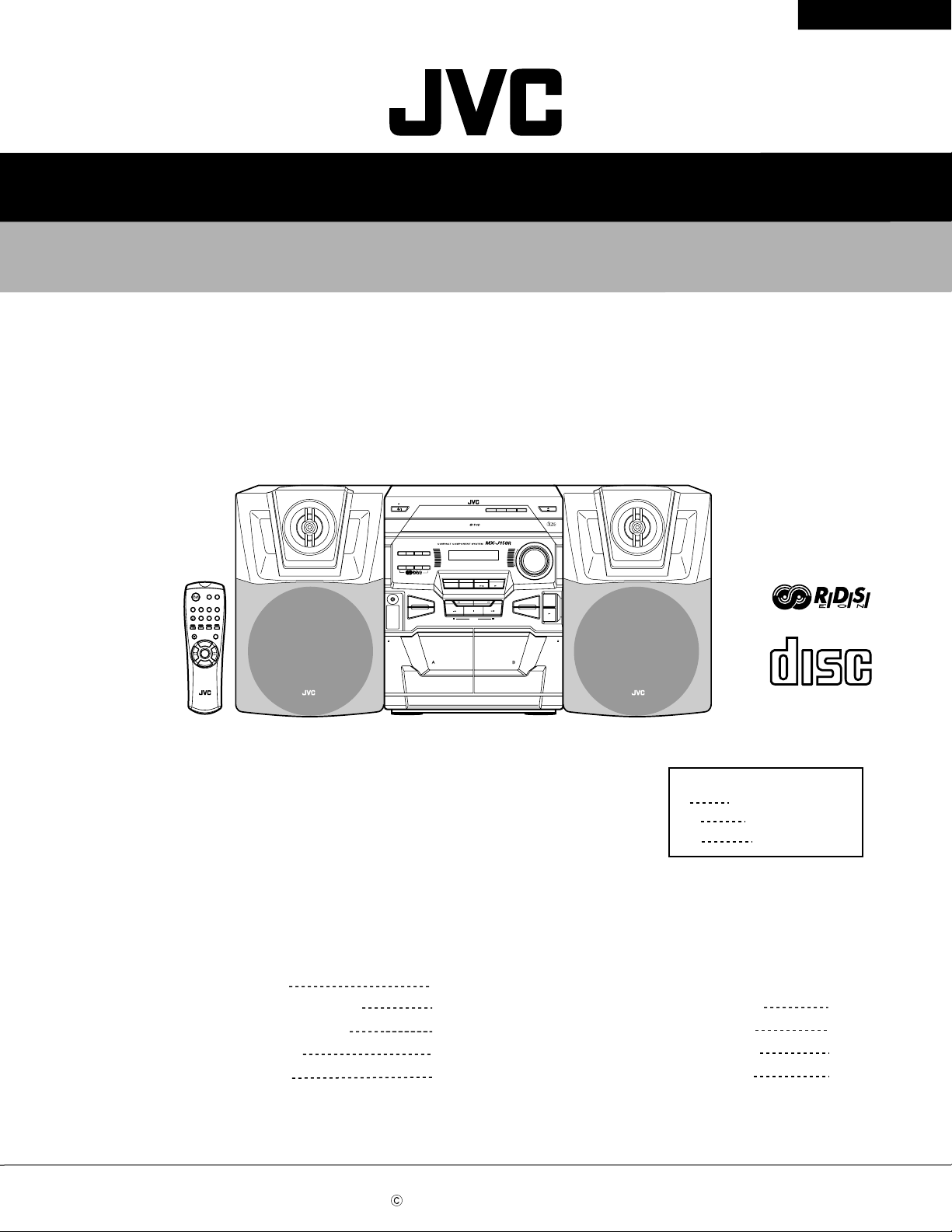
SERVICE MANUAL
COMPACT COMPONENT SYSTEM
MX-J150R
MX-J150R
STANDBY
CLOCK
COUNTER
ACTIVE
SOUND
BASS EX.
/TIMER
RESET
MODE
DEMO
PTY
DISPLA
– SELECT +
MODE
/EON
Y
TIMER
ON/OFF
SLEEP
SOUND
ACTIVE
PROGRAM
REPEAT
MODE
BASS EX.
/SET
TAPEA/B
CD
TUNING MODE FM MODE
TAPE
CD
FM/AM AUX
DISC SKIP
.
L
VO
+
F
ADE
MUTING
.
L
VO
–
RM–SMXJ100E
REMOTE CONTROL
PROGRAM/SET
PHONES
REPEAT
COMPU
PLAY
CONTROL
PLAY REC/PLAY
FULL-LOGIC CONTROL
AUX FM/AM
–
PLAY & EXCHANGER
CD TAPE
-
TUNING TUNING +
PRESET
CD SYNCHRO RECORDING
CD1CD2CD
+
OPEN / CLOSE
DISC CHANGE
3
COMPACT
DIGITAL AUDIO
VOLUME
+
–
CD REC
START
TAPE A/B
REC/PAUSE
A B
DUBBING
EJECTEJECT
COMPACT
DIGITAL AUDIO
SP-MXJ150R SP-MXJ150RCA-MXJ150R
Area Suffix
E
EN
EV
Continental Europe
Northern Europe
Eastern Europe
Contents
Safety precautions
Important for laser products
Preventing static electricity
Disassembly method
Adjustment method
COPYRIGHT 2000 VICTOR COMPANY OF JAPAN, LTD.
1-2
1-3
1-4
1-5
1-19
Flow of functional operation
until TOC read
Maintenance of laser pickup
Replacement of laser pickup
Description of major ICs
1-23
1-24
1-24
1-25
No.20858
Oct. 2000
Page 2
MX-J150R
Safety Precautions
1. This design of this product contains special hardware and many circuits and components specially
for safety purposes. For continued protection, no changes should be made to the original design
unless authorized in writing by the manufacturer. Replacement parts must be identical to those
used in the original circuits. Services should be performed by qualified personnel only.
2. Alterations of the design or circuitry of the product should not be made. Any design alterations of
the product should not be made. Any design alterations or additions will void the manufacturer`s
warranty and will further relieve the manufacture of responsibility for personal injury or proper ty
damage resulting therefrom.
3. Many electrical and mechanical par ts in the products have special safety-related characteristics.
These characteristics are often not evident from visual inspection nor can the protection afforded
by them necessarily be obtained by using replacement components rated for higher voltage,
wattage, etc. Replacement parts which have these special safety characteristics are identified in
the Parts List of Service Manual. Electrical components having such features are identified by
shading on the schematics and by ( ) on the Parts List in the Service Manual. The use of a
substitute replacement which does not have the same safety characteristics as the recommended
replacement parts shown in the Parts List of Service Manual may create shock, fire, or other
hazards.
4. The leads in the products are routed and dressed with ties, clamps, tubings, barriers and the
like to be separated from live parts, high temperature parts, moving parts and/or sharp edges
for the prevention of electric shock and fire hazard. When service is required, the or iginal lead
routing and dress should be observed, and it should be confirmed that they have been returned
to normal, after re-assembling.
5. Leakage current check (Electrical shock hazard testing)
After re-assembling the product, always perform an isolation check on the exposed metal parts
of the product (antenna terminals, knobs, metal cabinet, screw heads, headphone jack, control
shafts, etc.) to be sure the product is safe to operate without danger of electrical shock.
Do not use a line isolation transformer during this check.
Plug the AC line cord directly into the AC outlet. Using a "Leakage Current Tester", measure
the leakage current from each exposed metal parts of the cabinet , particularly any exposed
metal part having a return path to the chassis, to a known good earth ground. Any leakage
current must not exceed 0.5mA AC (r.m.s.)
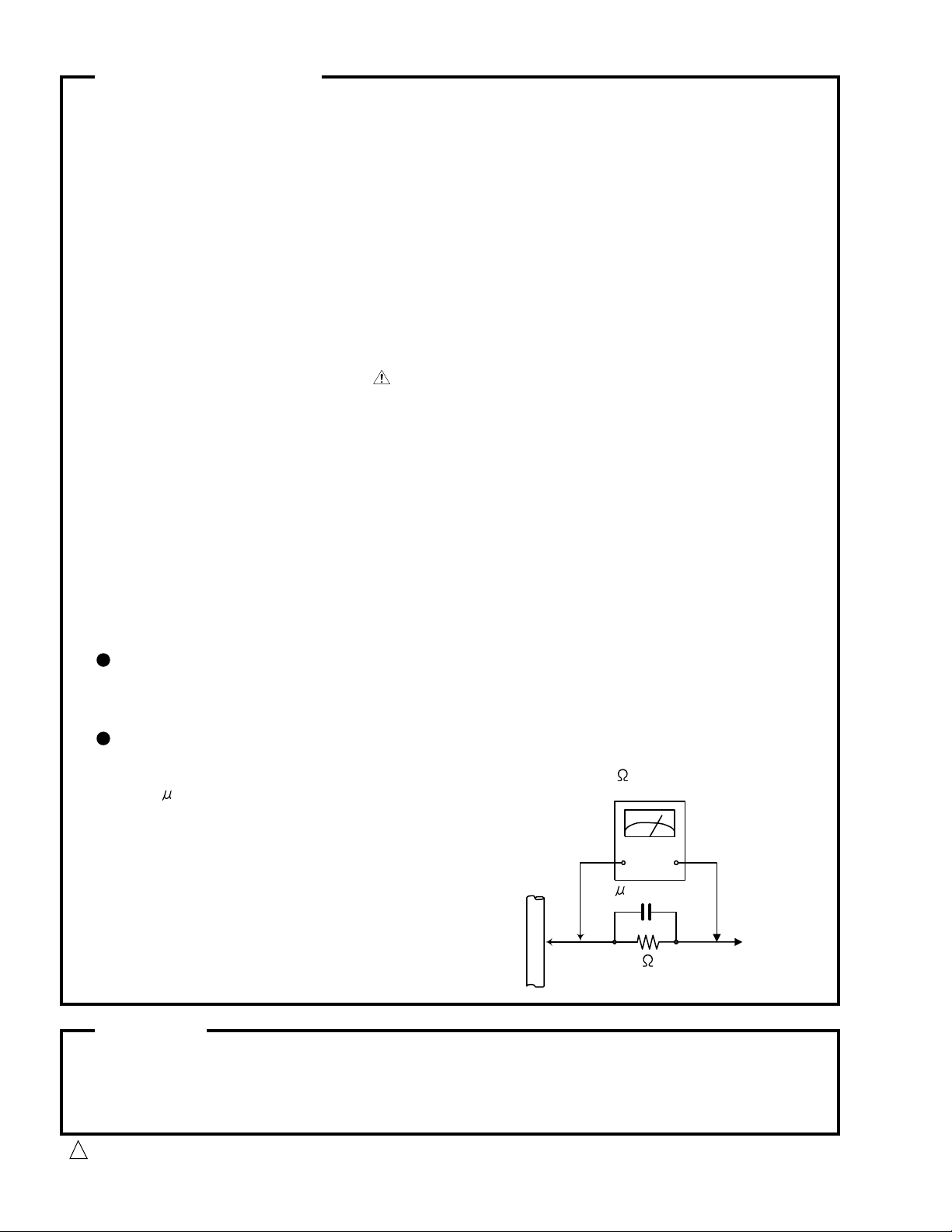
Alternate check method
Plug the AC line cord directly into the AC outlet. Use an AC voltmeter having 1,000 ohms
per volt or more sensitivity in the following manner. Connect a 1,500 10W resistor paralleled by
a 0.15 F AC-type capacitor between an exposed
metal part and a known good earth ground.
Measure the AC voltage across the resistor with the
AC voltmeter.
Move the resistor connection to each exposed metal
part, par ticularly any exposed metal part having a
return path to the chassis, and measure the AC
voltage across the resistor. Now, reverse the plug in
the AC outlet and repeat each measurement. Voltage
measured any must not exceed 0.75 V AC (r.m.s.).
This corresponds to 0.5 mA AC (r.m.s.).
0.15 F AC TYPE
1500 10W
Good earth ground
AC VOLTMETER
(Having 1000
ohms/volts,
or more sensitivity)
Place this
probe on
each exposed
metal part.
Warning
1. This equipment has been designed and manufactured to meet international safety standards.
2. It is the legal responsibility of the repairer to ensure that these safety standards are maintained.
3. Repairs must be made in accordance with the relevant safety standards.
4. It is essential that safety critical components are replaced by approved parts.
5. If mains voltage selector is provided, check setting for local voltage.
Burrs formed during molding may be left over on some parts of the chassis. Therefore,
pay attention to such burrs in the case of preforming repair of this system.
1-2
CAUTION
!
Page 3
Important for laser products
MX-J150R
1.CLASS 1 LASER PRODUCT
2.DANGER : Invisible laser radiation when open and inter
lock failed or defeated. Avoid direct exposure to beam.
3.CAUTION : There are no serviceable parts inside the
Laser Unit. Do not disassemble the Laser Unit. Replace
the complete Laser Unit if it malfunctions.
4.CAUTION : The compact disc player uses invisible
laserradiation and is equipped with safety switches
whichprevent emission of radiation when the drawer is
open and the safety interlocks have failed or are de
feated. It is dangerous to defeat the safety switches.
VARNING : Osynlig laserstrålning är denna del är öppnad
och spårren är urkopplad. Betrakta ej strålen.
VARO : Avattaessa ja suojalukitus ohitettaessa olet
alttiina näkymättömälle lasersäteilylle.Älä katso
säteeseen.
5.CAUTION : If safety switches malfunction, the laser is able
to function.
6.CAUTION : Use of controls, adjustments or performance of
procedures other than those specified herein may result in
hazardous radiation exposure.
CAUTION
!
Please use enough caution not to
see the beam directly or touch it
in case of an adjustment or operation
check.
ADVARSEL : Usynlig laserstråling ved åbning , når
sikkerhedsafbrydere er ude af funktion. Undgå
udsættelse for stråling.
ADVARSEL : Usynlig laserstråling ved åpning,når
sikkerhetsbryteren er avslott. unngå utsettelse
for stråling.
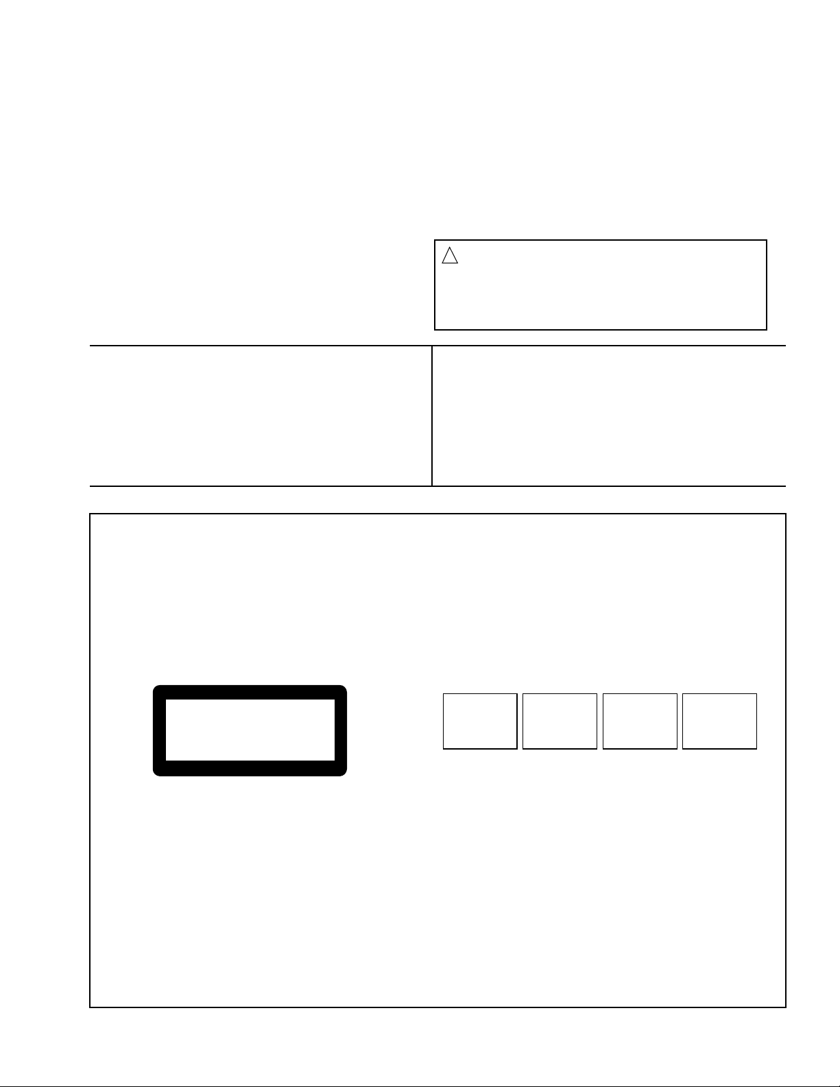
REPRODUCTION OF LABELS
CLASSIFICATION LABEL, PLACED ON REAR ENCLOSURE WARNING LABEL, PLACED INSIDE THE UNIT
ADVARSEL: Usynlig laserstråling ved åbning, når
sikkerhedsafbrydere er ude
af funktion. Undgå udsættelse for stråling (d)
CLASS 1
LASER PRODUCT
DANGER: Invisible laser
radiation when open and
interlock failed or defeated.
AVOID DIRECT EXPOSURE
TO BEAM. (e)
VARNING: Osynlig laserstrålning när denna del är
öppnad och spärren är
urkopplad. Betrakta ej
strålen. (s)
VARO: Avattaessa ja suojalukitus ohitettaessa olet
alttiina näkymättömälle
lasersäteilylle. Älä katso
säteeseen. (f)
1-3
Page 4
MX-J150R
Preventing static electricity
1. Grounding to prevent damage by static electricity
Electrostatic discharge (ESD), which occurs when static electricity stored in the body, fabric, etc. is discharged,
can destroy the laser diode in the traverse unit (optical pickup). Take care to prevent this when performing repairs.
2. About the earth processing for the destruction prevention by static electricity
In the equipment which uses optical pick-up (laser diode), optical pick-up is destroyed by the static electricity of
the work environment.
Be careful to use proper grounding in the area where repairs are being performed.
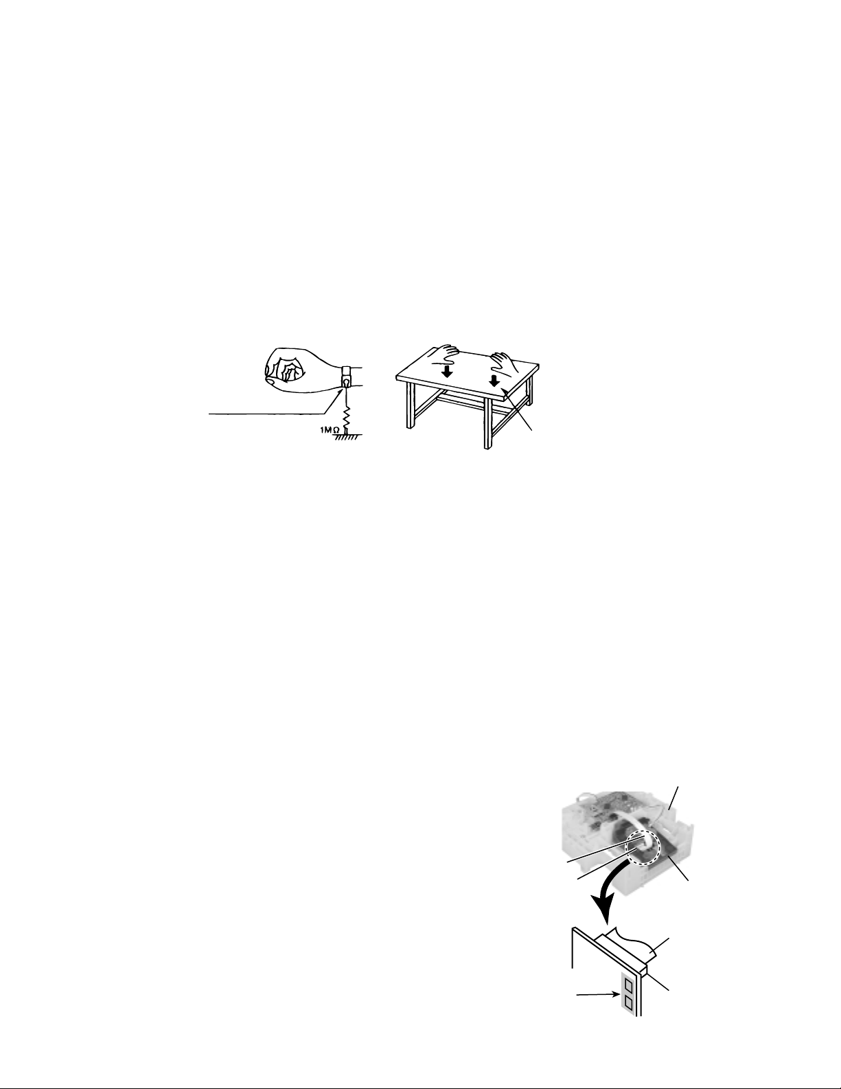
2-1 Ground the workbench
Ground the workbench by laying conductive material (such as a conductive sheet) or an iron plate over
it before placing the traverse unit (optical pickup) on it.
2-2 Ground yourself
Use an anti-static wrist strap to release any static electricity built up in your body.
(caption)
Anti-static wrist strap
Conductive material
(conductive sheet) or iron plate
3. Handling the optical pickup
1. In order to maintain quality during transport and before installation, both sides of the laser diode on the
replacement optical pickup are shorted. After replacement, return the shorted parts to their original condition.
(Refer to the text.)
2. Do not use a tester to check the condition of the laser diode in the optical pickup. The tester's internal power
source can easily destroy the laser diode.
4. Handling the traverse unit (optical pickup)
1. Do not subject the traverse unit (optical pickup) to strong shocks, as it is a sensitive, complex unit.
2. Cut off the shorted part of the flexible cable using nippers, etc. after replacing the optical pickup. For specific
details, refer to the replacement procedure in the text. Remove the anti-static pin when replacing the traverse
unit. Be careful not to take too long a time when attaching it to the connector.
3. Handle the flexible cable carefully as it may break when subjected to strong force.
4. It is not possible to adjust the semi-fixed resistor that adjusts the laser power. Do not turn it
Attention when CD mechanism assembly is decomposed
*Please refer to "Disassembly method" in the text for pick-up and how to
detach the CD mechanism assembly.
CD changer unit
1. Remove the CD changer unit.
2. Remove the CD changer mechanism.
3. Solder is put up before the card wire is removed from the pickup unit
connector on the CD mechanism assembly.
(When the card wire is removed without putting up solder, the CD pick-up
assembly might destroy.)
4. Please remove solder after connecting the card wire with the pickup unit
connector when you install picking up in the substrate.
1-4
Card wire
Pickup unit
connector
Soldering
Fig.2
Fig.1
CD changer
mechanism
Card wire
Pickup unit
connector
Page 5
MX-J150R
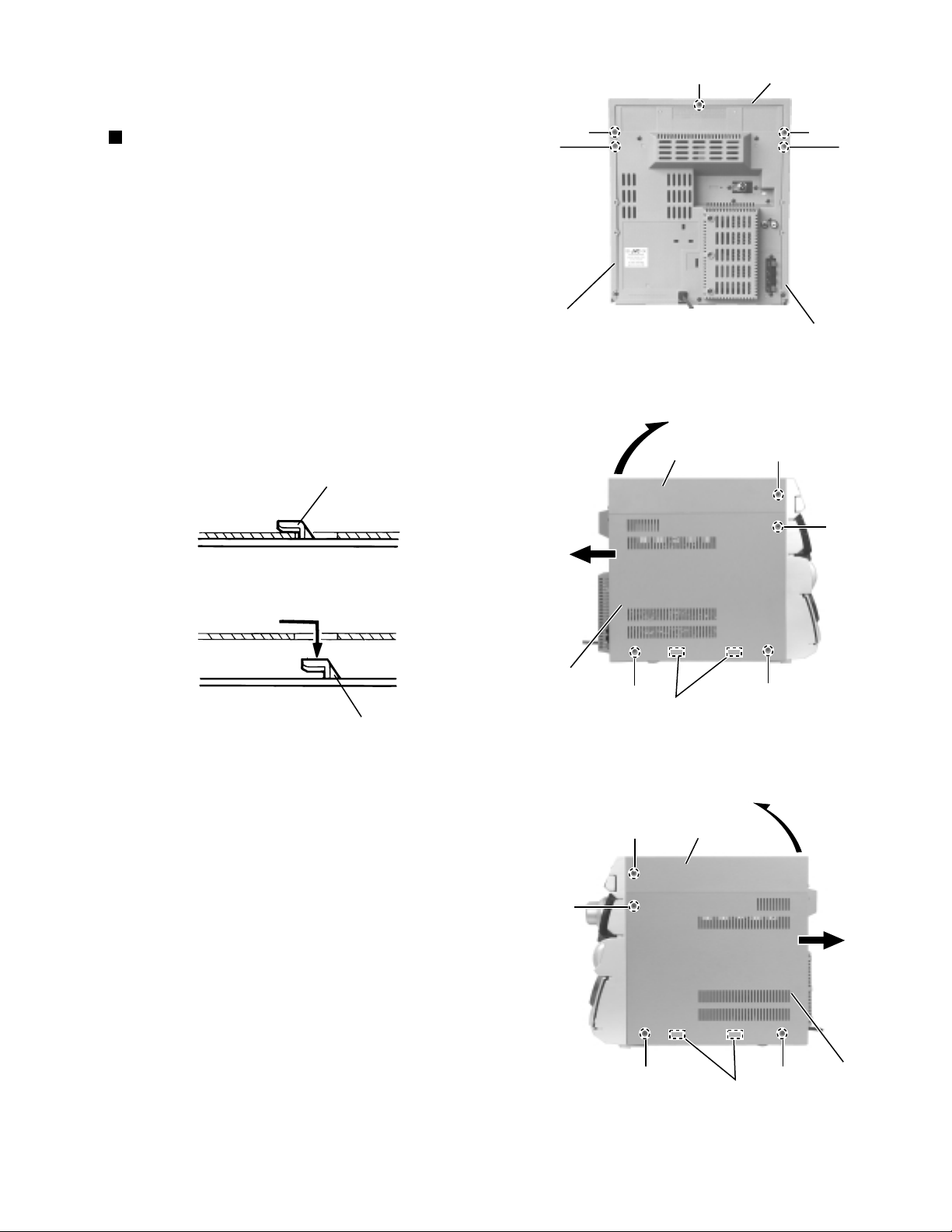
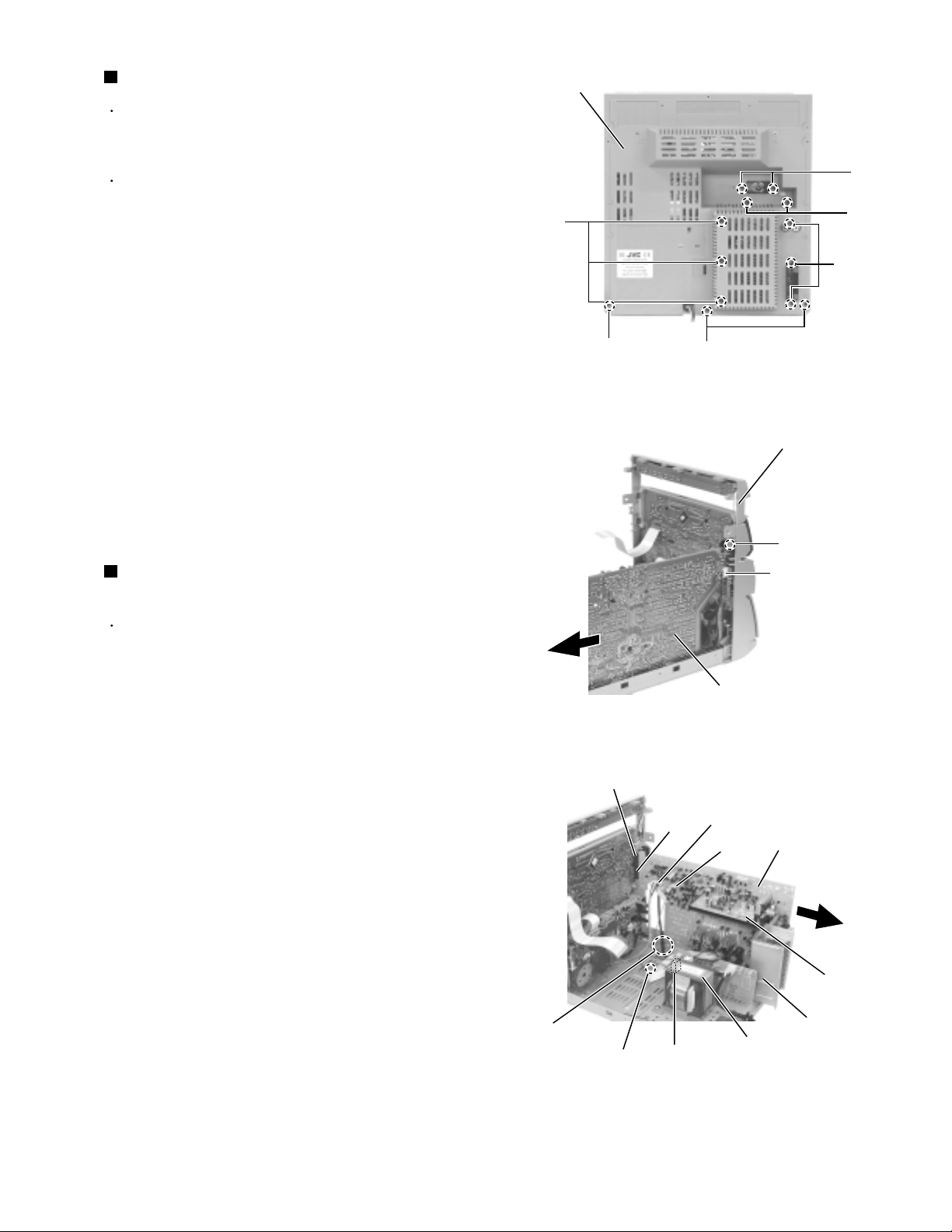
Remove the three screws A on the back of the body
and the two screws B on both sides of the body.
Remove the top cover upward from behind.
Remove the two screws C attaching the side covers
on the back of the body and the six screws D on both
sides.
Slide the right and left covers backward and unhook
the two hooks a in the lower part of the side covers
as shown in Fig.2-2.
1.
2.
3.
4.
<Main body>
Removing the top cover & the side
covers (See Fig.1 to 3)
Disassembly method
Fig.1
Fig.2Fig.2-2
Fig.3
Top cover
A
A
A
C
C
Side cover (L)
Side cover (R)
Side cover (R)
B
D
D
D
Top cover
Hooks a
Top cover
Hooks a
B
D
D
D
Side cover (L)
Hook
Hook
1-5
Page 6
MX-J150R
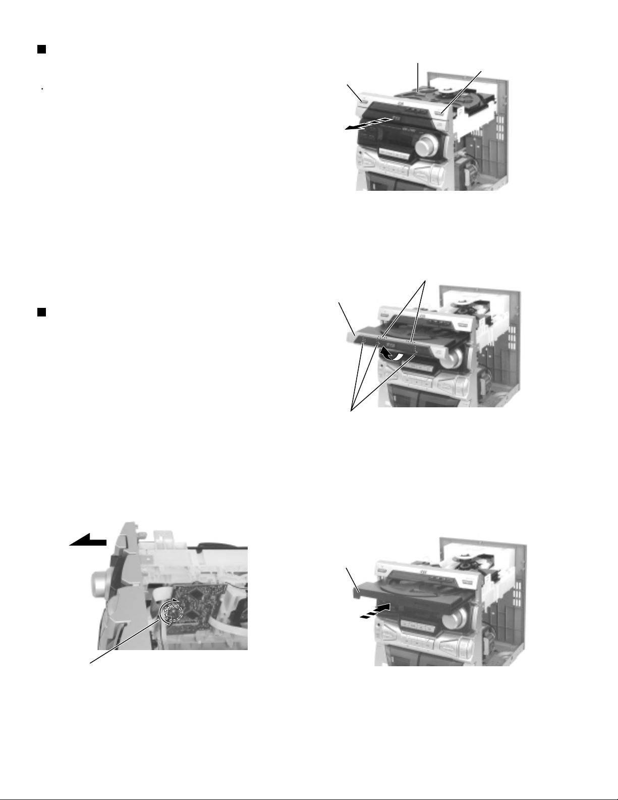
Removing the CD tray fitting
(See Fig.4 to 6)
Prior to performing the following procedure, remove
the top cover and the side covers.
ATTENTION:
1.
Press the POWER button. Press the OPEN/CLOSE
button to eject the CD tray.
2.
Move the CD tray fitting upward and release the joint
b.
3.
Press the OPEN/CLOSE button to insert the CD tray.
Be sure to remove the CD tray fitting
before removing the CD changer unit.
Removing the CD tray fitting
(See Fig.5 to 7)
CD tray
OPEN/CLOSE button
POWER button
Fig.4
Joint b
CD tray fitting
- How to eject the CD tray without turning on power -
1.
Turn the black loading pulley gear marked c from the
back of the CD changer unit as shown in Fig.7 and
draw the CD tray toward the front.
2.
Move the CD tray fitting upward and release the joint
b.
3.
Push and insert the CD tray manually.
Joint b
Fig.5
CD tray
Marked c
Loading pulley gear
1-6
Fig.7
Fig.6
Page 7
MX-J150R
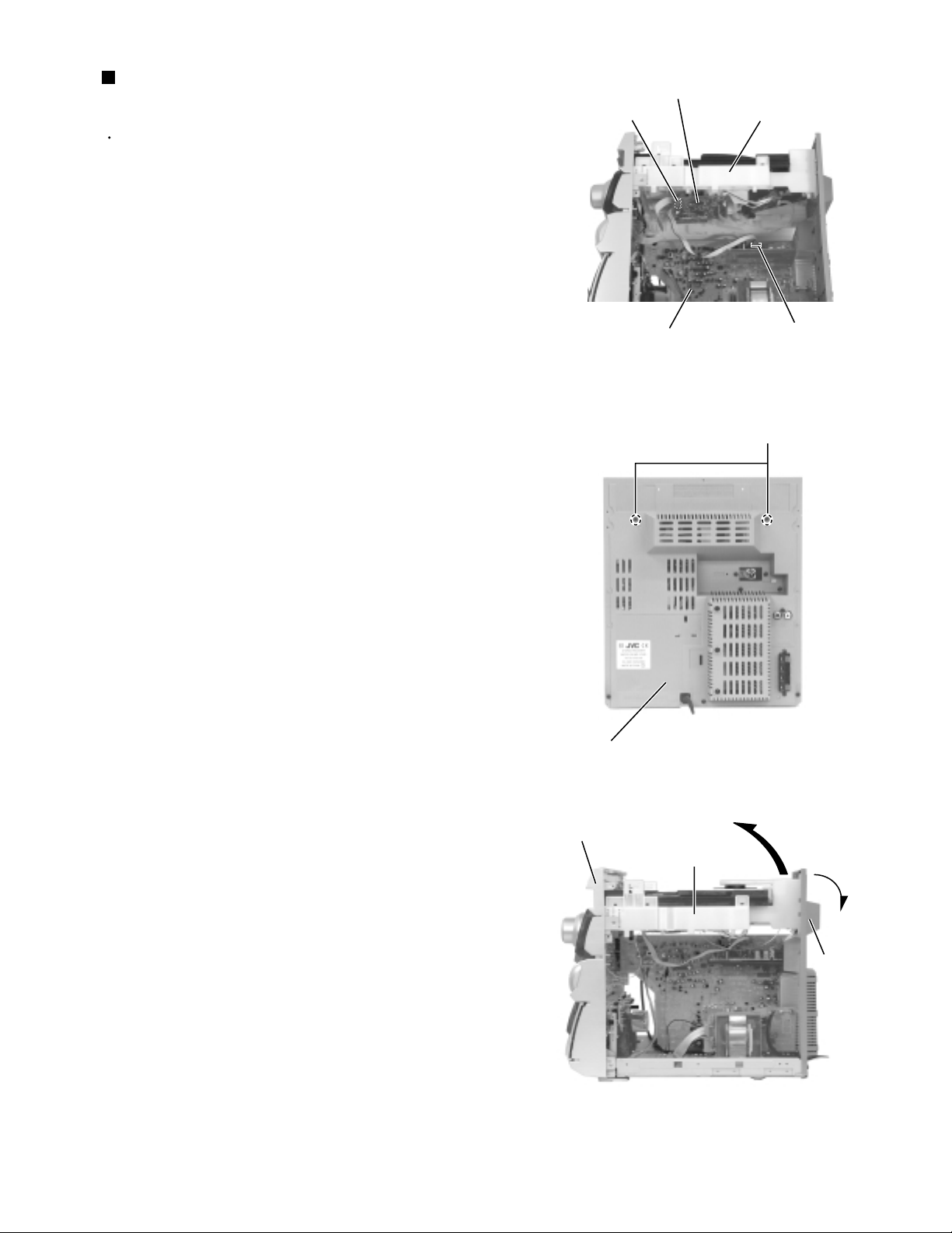
Prior to performing the following procedure, remove
the top cover, the side covers and the CD tray fitting.
Disconnect the card wire from connector SCW1 of
the CD servo board on the back of the CD changer
unit.
Disconnect the harness from connector FW2 on the
inner side of the main board in the body.
Remove the two screws E attaching the CD changer
unit on the back of the body.
Draw the CD changer unit upward from behind while
pulling the rear panel outward.
1.
2.
3.
4.
Removing the CD changer unit
(See Fig.8 to 10)
Fig.8
Fig.9
Fig.10
SCW1
CD servo board
CD changer unit
Main board
FW2
Rear panel
E
Rear panel
Front panel assembly
CD changer unit
1-7
Page 8
MX-J150R
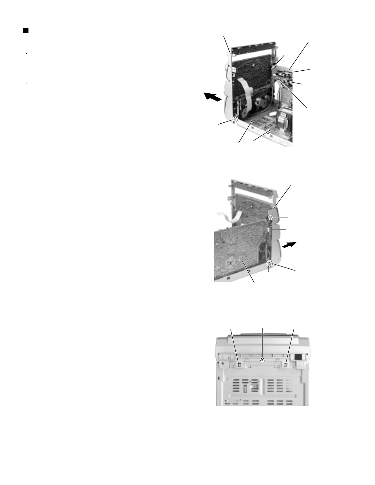
Removing the front panel assembly
(See Fig.11 to 13)
Prior to performing the following procedure, remove
the top cover, the side covers, the CD tray fitting and
the CD changer unit.
There is no need to remove the rear panel.
1.
Disconnect the harness from head wire connector
DW1 and DW2 on the inner side of the main board in
the body.
2.
Disconnect the harness from connector HCW1 of the
headphone board on the right side of the body.
3.
Remove the screw F and the two screws G attaching
the front panel assembly on both sides of the body.
Remove the screw V attaching the earth terminal
extending from the front compartment.
4.
Remove the screw H attaching the front panel
assembly on the bottom of the body.
5.
Release the two joints d on both sides and two joints
e on the bottom of the body using a screwdriver. At
the same time, disconnect the front compartment
from connector CCW1 and CCW2 of the main board.
Front panel assembly
Joint d
G
earth wire
Main board
CCW1
CCW2
DW2
DW1
V
Fig.11
Front panel assembly
F
Headphone board
HCW1
Joint e
Main board
Fig.12
H
Fig.13
G
Joint d
Joint e
1-8
Page 9
MX-J150R
Prior to performing the following procedure, remove
the top cover, the side covers, the CD tray fitting and
the CD changer unit.
There is no need to remove the front panel
assembly.
Remove the seven screws I attaching the main
board and the tuner board to the rear panel on the
back of the body.
Remove the three screws J attaching the heat sink
to the rear panel on the back of the body.
Remove the three screws K attaching the rear panel
on the back of the body.
1.
2.
3.
Removing the rear panel (See Fig.14)
Prior to performing the following procedure, remove
the rear panel.
Disconnect the harness from connector HCW1 of the
headphone board on the right side of the body.
Release the harness from the clamp in the body.
Disconnect the harness from head wire connector
DW1 and DW2 extending to the main board in the
body.
Disconnect the harness from connector RCW1 of the
power transformer.
Remove the screw L attaching the earth terminal to
the base chassis.
Remove the screw F attaching the front panel
assembly.
Disconnect connector CCW1 and CCW2 connected
to the main board.
1.
2.
3.
4.
5.
6.
Removing the main board
(See Fig.15 and 16)
Fig.14
Fig.15
Fig.16
I
Rear panel
I
I
K
K
J
Front panel assembly
Main board
Headphone board
HCW1
Main board
Heat sink
Tuner board
DW2
DW1
CCW2
CCW1
Power transformer
RCW1
L
Clamp
F
1-9
Page 10
MX-J150R
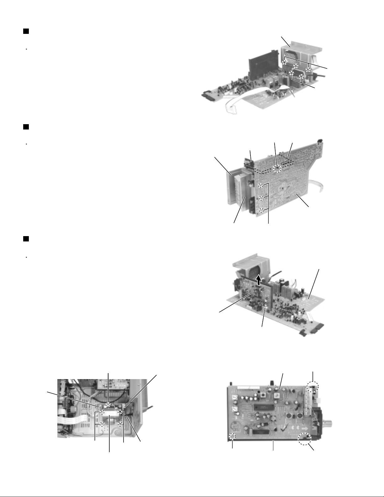
Removing the heat sink
(See Fig.17 and 18)
Prior to performing the following procedure, remove
the main board.
1.
Remove the three screws M attaching the heat sink
cover plate.
2.
Remove the two screws N attaching the power IC to
the heat sink and the three screws O attaching the
heat sink to the main board.
Removing the tuner board
(See Fig.18 to 20)
The tuner board can be removed even if the main
board is attached.
1.
Release the joint tab f of the tuner board holder and
the main board, and disconnect connector FW1
connected to the main board. Remove the tuner
board assembly (Refer to Fig.18).
2.
Remove the screw P attaching the tuner board
holder. Release the two tabs g outward and remove
the tuner board from the holder.
Removing the power transformer
(See Fig .21)
Prior to performing the following procedure, remove
the top cover and the side covers.
Heat sink cover plate
Tuner board
Heat sink cover plate
Heat sink
Fig.17
Joint tab f
O
Fig.18
M
N
FW1
Main board
Main board
1.
Disconnect the power cord from connector RCW2 of
the power transformer.
2.
Disconnect the harness from connector RCW1 of the
power transformer.
3.
Remove the four screws Q attaching the power
transformer and the screw R attaching the earth
terminal.
ATTENTION:
RCW1
Prior to disconnecting the power cord
from the body, remove the rear panel.
R
Q
Power transformer
Fig.21
Q
RCW2
Power cord
Tuner board
FW1
Tuner board holder
P
Fig.19
Tuner board
Fig.20
Tab g
Tab g
1-10
Page 11

MX-J150R
<Front panel assembly>
Prior to performing the following procedure, remove
the top cover, the side covers, the CD tray fitting and
the front panel assembly.
Removing the power / CD switch board
(See Fig.22)
1.
Remove the three screws S attaching the power/CD
switch board and release the three tabs h outward.
2.
Disconnect the harness from connector UCW9 of the
power/CD switch board.
Removing the front board
(See Fig.22 and 23)
Prior to performing the following procedure, remove
the power / CD switch board.
1.
Pull out the volume knob toward the front.
Tab h
T
T
System board
T
Mechanism board
Cassette mechanism assembly
Front panel assembly
S
Tab h
Fig.22
S
Tab h
UCW9
Power / CD
switch board
T
T
Headphone
board
T
Volume knob
2.
Disconnect the card wire from the mechanism board
of the cassette mechanism assembly.
3.
Remove the nine screws T attaching the front board.
Removing the headphone board
(See Fig.24)
1.
Remove the system board temporarily and remove
the screw U attaching the headphone board. Pull out
the headphone board.
Removing the cassette mechanism
assembly (See Fig.25)
1.
Disconnect the card wire from the mechanism board
of the cassette mechanism assembly.
2.
Remove the seven screws W attaching the cassette
mechanism assembly.
Fig.23
U
Headphone board
Fig.24
Mechanism board
W
W
Cassette mechanism assembly
W
W
Fig.25
1-11
Page 12

MX-J150R
<CD changer unit>
Prior to performing the following procedure, remove
the CD changer unit.
Removing the CD tray (See Fig.26 to 28)
1.
Turn the black loading pulley gear marked c on the
under side of the CD changer unit in the direction of
the arrow and draw the CD tray toward the front until
it stops.
2.
Disconnect the card wire from connector SCW5 of
the CD servo board on the upper side of the CD
changer unit.
3.
Push down the two tray stoppers marked i and pull
out the CD tray.
Loading pulley gear marked c
CD tray
CD tray
Fig.26
Reinstall the CD tray (See Fig.29 to 30)
1.
Align the gear-cam with the gear-tray as shown
fig.29, then mount the CD tray.
2.
When assembling the CD tray, take extreme care not
engage with gear - synchro.
Gear-cam
Gear-tray
Fig.27
Tray stopper marked i
CD tray
Tray stopper marked i
CD servo board
SCW5
Fig.28
Gear-convert
Gear-convert
1-12
Gear-tray
Gear-cam
timing point
Gear-tray
CD tray
Fig.29 Fig.30
Gear-synchro
Page 13

Prior to performing the following procedure, remove
the CD tray.
Release the two tabs j attaching the sensor board on
the under side of the CD tray.
Disconnect the harness from connector CW1 on the
sensor board and release the harness from the two
hooks k. Remove the sensor board.
Remove the screw X attaching the tray turn table.
Detach the tray turn table from the tray.
Pull outward the tab m attaching the tray turn table
motor assembly on the upper side of the tray and
detach the tray turn table motor assembly from the
tray.
1.
2.
3.
4.
Removing the sensor board & the tray
turn table motor assembly
(See Fig.31 to 33)
Fig.32
Fig.31
Fig.33
Tab j
Tab j
Hooks k
Sensor board
CW1
Tray turn table
Tray
X
Tray turn table motor assembly
Tab m
MX-J150R
1-13
Page 14

MX-J150R
Removing the belt, the CD servo board &
the switch board (See Fig.34 and 35)
Prior to performing the following procedure, remove
the CD tray.
1.
Detach the belt from the pulley on the upper side of
the CD changer unit (Do not stain the belt with
grease).
2.
Disconnect the card wire from the pickup unit
connector on the under side of the CD changer unit.
3.
Disconnect the motor wire harness from connector
on the CD mechanism board.
4.
Remove the two screws Y attaching the CD servo
board. First release the n side of the two tabs n and
two tabs o attaching the CD servo board motor to
raise the CD servo board slightly, then release the o
side.
If the tabs n and o are hard to release, it is
recommendable to unsolder the two soldered parts
on the motor terminal of the CD servo board.
Disconnect the terminal CW3 connected to the
switch board and remove the CD servo board.
Tabs p
CD changer unit
Fig.34
Y
CD servo board
Tabs o
Belt
Soldered parts
Motor
Tabs n
5.
Release the three tabs p attaching the switch board
outward and detach the switch board.
Switch board
CW3
Pickup unit connector
Fig.35
CD mechanism board
motor connector
1-14
Page 15

Disconnect the harness from connector on the CD
mechanism board in the CD mechanism assembly
on the under side of the CD changer unit. Disconnect
the card wire from the pickup unit connector.
Remove the screw Z attaching the shaft on the right
side of the CD mechanism holder assembly. Pull
outward the stopper fixing the shaft on the left side
and remove the CD mechanism holder assembly
from behind in the direction of the arrow.
Turn the CD mechanism holder assembly half
around the lift up slide shaft r of the CD mechanism
holder assembly until the turn table is reversed, and
pull out the CD mechanism holder assembly.
1.
2.
3.
Removing the CD mechanism holder
assembly (mechanism included)
(See Fig.36 to 39)
Fig.36
Fig.37
Fig.38
Fig.39
Motor connector
CD mechanism assembly
CD changer unit
Pickup unit connector
Z
CD mechanism holder assembly
Stopper
CD mechanism holder assembly
Lift up slide shaft r
Lift up slide shaft
CD mechanism holder assembly
MX-J150R
1-15
Page 16

MX-J150R
<CD mechanism section>
•
Removing the CD mechanism holder from the CD
chassis to remove the CD mechanism.
(Refer to "Removing the CD mechanism holder
assembly" (Pag.2-11))
Removing the pickup unit.
1. Loosen the two screws A fixing the chassis.(Fig.1)
2. Removing the feed gear stopper c on the
bottom of the mechanism and pull out the gear.
(Fig.1, Fig.3, Fig.4)
3. Pull out the shaft by opening the pickup shaft
stopper outward to unlock.(Fig.1, Fig.2)
4. Removing the pickup unit.(Fig.1)
Removing the motor board.
1. Unsolder the motor terminal on the motor board.(Fig.3)
2. Remove the motor board.(Fig.3)
Removing the feed motor.
Remove the two motor fixing screws at B and
removing the feed motor.(Fig.1, Fig.3)
Removing the spindle motor.
The spindle motor cannot be removed as a single unit.
When removing the spindle motor, change the chassis
and turntable together as aunit.(Fig.5)
Stopper
A
A
Stopper
Shutter
B
Fig.1
Fig.2
Shaft
Pickup unit
Feed Gear
Shaft
Screw
W
Turn table
Screw
Spindle motor
Motor board
Feed motor
Spindle motor
Unsolder
c
Unsolder
Fig.3
c
1-16
B
Chassis
(Feed gear stopper)
Fig.4Fig.5
Page 17

MX-J150R
<Cassette mechanism section>
• Removing the record/playback mechanism.
Removing the R/P head.
1. Remove the screw A on the right side of the
R/P head.(Fig.1, Fig.2)
2. Remove the screw B on the left side of the
R/P head.(Fig.1, Fig.2)
Remove the erase head.
Remove the screw C fixing the erase head.(Fig.1)
Removing the pinch roller.
1. Pull out the pinch roller by opening the pinch
roller stopper outward to unlock .(Fig.3)
2. When reassembling the pinch roller, refer to
fig. 4 to hook up the spring.
Fig.1
Fig.2
Fig.3
Fig.4
R/P Head
R/P Head
E. Head
Spring
Stopper
Pinch roller
assembly
A
A
B
B
C
Pinch roller
Pinch roller
stopper
Pinch roller
Pinch roller
spring
Return spring
Return spring
Return spring
1-17
Page 18

MX-J150R
Removing the motor.
1. Remove the two screws D fixing the motor.
Be careful to grease's splash when the
drive belt comes off.(Fig.5, Fig.6)
2. Unsolder the motor terminal.(Fig.5)
Removing the mechanism board.
1. Unsolder the four parts a on the solenoid
coil terminal.(Fig.5)
2. Remove the two screws E fixing the board.(Fig.5)
3. Unhook the three parts b from the board.(Fig.5)
4. Remove the mechanism board.(Fig.5)
Removing the flywheel.
Remove the cut-washers at c and d from the
capstan shaft, then remove the flywheel.
When reassembling the flywheel,
be sure to use new washers as they
cannot be reused.(Fig.8, Fig.9)
a
E
Drive belt
Mecha.
board
terminal
b
Motor
Motor
D
D
Fig.5
Drive belt
Fig.6
E
Drive belt
Motor
b
a
1-18
Sleeve
Flywheel
c
Washer
Sleeve
d
FR belt
Capstan
washer
Flywheel
Fig.7
FR belt
Fig.8Fig.9
Capstan
washer
Flywheel
Page 19

Adjustment method
Tuner
MX-J150R
Adjustment Location of Tuner PCB
*
ITEAM
Received FREQ.
Adjustment
point
Output
MAIN
PCB
AM(MW) OSC Adjustment
520~1720 KHz
Adjustment
Non-
1~7.0±0.5V
VT GND
AM(MW) RF Adjustment
590 KHz
MW-ANT
Maximum Output(Fig1-4)
TESTER
Fig 1-4 OSC Voltage
1-19
Page 20

MX-J150R
FM THD Adjustment
SSG FREQ.
98 MHz
Adjustment
point
FM DETECTOR COIL
(TL3)
Output
60 dB
Minimum Distortion (0.3% below)
(Figure 1-1)
FM Search Level Adjustment
SSG FREQ.
Adjustment
point
(TSR1)
Output
BEACON
SENSITIVITY
SEMI-VR(20K½)
28 dB(±2dB)
98 MHz
Output
GND
FM S.S.G
FM
Antenna
Terminal
Speaker
Terminal
SET
Input
output
Distortion Meter
Figure1-1 IF CENTER and THD Adjustment
FM Antenna
SET
FM IN
FM S.S.G
28 dB
GND
Oscilloscope
Input
Adjust TSR1 so that “TUNED” of FL T
is lighted (Figure 1-2)
*Adjust FM S.S.G level to 28dB
AM(MW) I.F Adjustment
SSG FREQ.
Frequency
450 kHz
520 kHz
Adjustment
point
AM I.F COIL
(TL2)
Maximum output (Figure 1-3)
Figure1-2 FM Auto Search Level Adjustment
60cm
OUTPUT
AM SSG
450KHZ
INPUT
AM ANT
IN
Speaker Terminal
OUTPUT
VTVM Oscilloscope
Figure1-3 AM I.F Adjustment
20 k½
TL2
1-20
Page 21

1. To adjust tape speed
Cassette deck
(GND)
VTVM
1) Measuring tape: i) MTT -111 (or equivalent)
(Tapes recorded with 3kHz)
ii) MTT-5512 (or equivalent)
2) Connect the cassette deck to the frequency counter
as in figure 1-5.
Notes
NOR
SPEED
Control
1
OUT
(connected
to the frequency
counter)
Turn UVR2 to
left and right
(FRONT PCB)
3KHz
Remark
Standard
To Adjust
Pre-Setup
Item
Step
Pre-Setup
Condition
1) Deck 1:MTT-111
2) Press PLAY
SW button
3) Deck 2:Same
as above
Cassette Deck
output
SPK OUT
Frequency Counter
Figure 1-5
Figure 1-6
SPK OUT
Recording /Play head
FWD PLAY
REVERSE PLAY
AZIMUTH control screw
Figure 1-7
In Out
Cassette Deck
Oscilloscope
±1%
range
Figure 1-8
Audio OSC.
SET
(MAIN PCB)
Oscilloscope
AUX IN
LINE OUT
VTVM
IN
DW2
IN OUT
TP
MX-J150R
1-21
Page 22

MX-J150R
2. To adjust playback lebel/REC
Notes
1) Before the actual adjustment, clean the play/recording
head.
2) Measuring tape :
i) MTT -114NA(or equivalent 12.5kHz AZIMUTH control)
ii) MTT-5512
3) The cassette deck is connections as shown in figure 1-7.
1 Adjust Deck 1 Play Level
Step
1
Item
AZIMUTH
Pre-Setup
Condition
TP1 OUT
(VTVM is
connected to
the scope)
Pre-Setup
After putting MTT114NA into Deck 1
- Press FWD PLAY
button.
2 Adjust Deck 2 Play Level/REC BIAS
Step
1
Item
AZIMUTH
Pre-Setup
Condition
TP1 OUT
(VTVM is
connected to
the scope)
Pre-Setup
After putting MTT 114NA into Deck 2
1)Press FWD PLAY
button.
2)Press REV PLAY
button.
To Adjust
- Turn the control
screw to as shown
in Figure 1-6.
To Adjust
- Turn the control
screw to as shown
in Figure 1-6.
Standard
Max output
and same phase
(both channels)
Standard
Max output
and same phase
(both channels)
Remark
After
adjustment
secure it with
REGION
LOCK.
Remark
After
adjustment
secure it with
REGION
LOCK.
1-22
2
Recording
Bias
Voltage
Fig 1-8
After putting MTT5512 into Deck 2
1)Press REC PLAY
button.
2)MAIN PCB DCW2,
connectted to VTVM
Turn DVR1,DVR2
to the right and left
7V(±0.5V)
Page 23

Flow of functional operation until TOC read
Power ON
Play Key
RESET a CD LSI
Confirm that the voltage at the pin38
of KB9223(IC922) is "L" "H".
MX-J150R
Check Point
LIMIT SW ON
SET Default value of
TE gain, TE balance
Automatic adjusting of
focus bias
Automatic adjusting of
FE offset
Automatic adjusting of
TE offset
LASER power ON
Detection of disk
Confirm that the voltage at the pin41
of KB9223(IC922) is "H" "L" "H".
Confirm that the voltage at the
pin70 of KB9223(IC922) is 3.5V.
Tracking error waveform at TOC reading
Pin 54 of
KB9223/TE
(IC922)
Approx
0.4V
2.50V
Disc states
to rotate
Approx.3.7sec
Disc is rotated
Automatic adjusting of
TE balance
Automatic adjusting of
TE gain
TOC reading
Play a disc
Confirm that the signal from pin46
of KB9223(IC922) is 3.5V as a
accelerated pulse during
approx.1.96s.
Confirm the waveform of
the Tracking error signal
at the pin 54 of KB9223(IC922).
Confirm the eye-pattern
at the pin74 of KB9223(IC922).
1-23
Page 24

MX-J150R
Maintenance of laser pickup
(1) Cleaning the pick up lens
Before you replace the pick up, please try to
clean the lens with a alcohol soaked cotton
swab.
(2) Life of the laser diode
When the life of the laser diode has expired,
the following symptoms will appear.
1. The level of RF output (EFM output:ampli
tude of eye pattern) will below.
Is the level of
RFOUT under
1.1V 0.2Vp-p?
YES
O.K
NO
Replace it.
Replacement of laser pickup
Turn off the power switch and,disconnect the
power cord from the AC outlet.
Replace the pickup with a normal one.(Refer
to "Pickup Removal" on the previous page)
Plug the power cord in,and turn the power on.
At this time,check that the laser emits for
about 3seconds and the objective lens moves
up and down.
Note: Do not observe the laser beam directly.
Play a disc.
Check the eye-pattern at TP1.
Finish.
(3) Semi-fixed resistor on the APC PC board
The semi-fixed resistor on the APC printed circuit board which is attached to the pickup is used to adjust the laser
power.Since this adjustment should be performed to match the characteristics of the whole optical block, do not
touch the semi-fixed resistor.
If the laser power is lower than the specified value,the laser diode is almost worn out, and the laser pickup should
be replaced.
If the semi-fixed resistor is adjusted while the pickup is functioning normally,the laser pickup may be damaged
due to excessive current.
1-24
Page 25

MX-J150R
KA22291 (DIC1) : Cassette amp.
23 22 21 8 20 19 18 15
24
16
17
9
1
2 3 4 5 7 6 10
11
12
13
14
PB
NF(2)
PR IN(2)
R/PSWMUTE
SW
MUTE
(IN2)
ALC RECOUT(2)
100K
PRE
RECORD
LREF
PLAYBACK
LREF
PRE
NF
100K
INPUT
PB.BIAS
REC.BIAS
INPUT
N.F
MODE CONTROL
/BIAS CIRCUIT
PU
NF(1)
PB IN(1) A/BSWPB GND MUTE
IN(1)
REC
OUT(1)
PB OUT(1)
REC GND
Vcc
Vcc
PBOUT(2)
100K
PRE
INPUT
N.F
ALC
DET
PRE
N.F
INPUT
REC NF(2)
REC IN(2)
REC IN(1)
REC IN(1)
100K
ALC TIME CONSTANT
R/P SW
A-IN
B-IN
A/B SELECT S/W
A-IN
B-IN
Description of major ICs
KA9258D (IC925) : 4-ch Motor driver
28 27 26 25 24 23 22 21 20 19 18 17 16 15
10K
T • S • D
1 2 3 4 5 6 7 8 9 10 11 12 13 14
+-
10K
LEVEL SHIFT
GND
VCC VCC
10K
REGULATOR
50K
10K
10K
10K
GND
10K
10K
MUTE
LEVEL SHIFT
-+
1-25
Page 26

MX-J150R
KB9223 (IC922) : ASSP(CD RF)
73
RF–
RFO
PD1
PD2
PD
LD
VR
ARF
IRF
ASY
EFM
RFI
DCB
74
65
66
63
67
F
68
E
79
EI
69
70
71
78
76
75
32
33
77
2
4
RF Amp
RF Amp
Focus Error Amp
FE-BIAS Adjustment
Tracking Error Amp
E/F Balance & Gain
Control
APC Amp
Center Voltage Amp.
RF Level AGC
&
Equalizer
EFM
Comparator
Defect Dectection
Circuit
FEI
TE1
WDCH
TRCNT
LOCH
ISTAT
RESET
MLT
MDATA
MCK
ATSC
TZC
59 54 22 30 29 31 38 37 36 35 51 52 58 26 28 27 3
Micom Data
Interface Logic
FE2
FLB
FGD
FS3
Focus Phase
Compensation
& Offset cancel circuit
Tracking Phase
Compensation Block
& Jump Pulse GEN.
MICOM TO SERVO CONTROL
AUTO SEQUENCER
ADJUSTMENT-FREE CONTROL
FS1 to
TM to
TM6
BAL1 to
BAL5
FS4
Built-in Post Filter Amp (L&R)
15 16 13 14 19 17 12 11 9 105
PS1 to
PS4
GA1 to
GAS
Sled Servo Amplifier
& Sled Kick GEN.
Spindle Servo LPF
(Double Speed)
MIRROR DETECTION
CIRCUIT
FOK DETECTION
CIRCUIT
60
47
48
57
49
50
53
55
62
61
43
44
42
46
45
23
24
25
6
39
1
40
FDFCT
FEFEO
TDFCT
TETEO
TE2
LPFT
TG2
TGU
SLO
SL–
SL+
SPDLO
SPDLSMDP
SMON
SMEF
FSET
MIRROR
MCP
FOK
1-26
DCC1
GC10
GC11
CH10
CH11
MUTEI
RRC
CH20
CH21
GC21
GC20
Page 27

KS9286B (IC928) : DSP/D-A Converter
S0S1
SBCK
MX-J150R
SDAT
EFMI
CNTVOL
DPFIN
DPFOUT
DPDO
SMEF
SMON
SMDP
SMSD
LOCK
XOUT
XIN
MDAT
MCK
MLT
TRCNT
/ISTAT
66
72
73
75
76
70
37
38
36
69
68
26
SUBCODE
SYNC
DETECTOR
EFM
PHASE
DETECTOR
5
3
4
2
9
8
DIGITAL
PLL
DIGITAL
CLV
SERVO
CPU
INTERFACE
MODE
SELECTOR
23BIT
SHIFT
REGISTER
FRAME SYNC
DETECTOR
PROTECTOR
INSERTER
X-TAL
TIMING
GENERATOR
TRACK
COUNTER
DIGITAL
OUTPUT
32
33
SUBCODE
OUTPUT
EFM
DEMODULATOR
ADDRESS
GENERATOR
16K
SRAM
ECC
INTERPOLATOR
DIGITAL
FILTER
& DE-EMPH
D/A
CONVERTER
SUBCODE-Q
REGISTER
30
SQDT
SQCK
29
8BIT DATA BUS
11
LRCHO
12
ADATAO
14
BCKO
77
BCKI
67
ADATAI
80
LRCHI
24
EMPH
17
VREFL1
22
VREFH1
63
62
61
XTALSEL
TESTO
CDROM
65
TEST1
7
DATX
19
20
RCHOUT
LCHOUT
1-27
Page 28

MX-J150R
LA1837 (TIC1) : FM IF/DET AM RF/IF/DET
1-28
Page 29

MX-J150R
LC72131D (HIC1) : PLL
1
22
XIN
XOUT
16
FMIN
15
AMIN
3
CE
4
DI
5
CL
6
DO
17
VDD
21
Vss
C2B
1/F
P0WER
ON
RESET
7 8 9 10
BO1 BO2 BO3 BO4
11
IO1
13
IO2
18
PD
19
AIN
20
ADUT
12
IFIN
REFERENCE
DIVIDER
PHASE DETECTOR
CHARGE PUMP
UNLOCK
DETECTOR
UNIVERSAL
COUNTER
DATA SHIFT REGISTER
LATCH
12bita PROGRAMMABLE
DIVIDER
SWALLOW COUNTER
1/16, 1/17 4D1ts
1/2
STK402-040 (AIC1)
1-29
Page 30

MX-J150R
LC75341 (FIC1) : Function
1-30
Page 31

BU1923F (RIC1) : RDS decoder
1. Pin layout
1
QUAL
Vref
MUX
VDD1
VSS1
VSS3
CMP
2
3
4
5
6
7
8
RDATA
2. Block diagram
16
15
14
13
12
11
10
9
RCLK
N.C.
XO
XI
VDD2
VSS2
T1
T2
VSS3
7
MX-J150R
CMP
8
MUX
Vref
VDD1
VSS1
VDD2
VSS2
4
3
5
Power supply
6
12
Digital
Power supply
11
100k
120k
Analog
Xl
13
100k
anti-aliasing
PLL
57kHz
RDS/ARI
14
X0
+
filter
Reference
clock
PLL
1187.5Hz
8th Switched
capacitor filter
Bi-phase
decoder
Measurement
circuit
10 9
T1
comparator
Differential
decoder
T2
16
RCLK
1
QUAL
2
RDATA
1-31
Page 32

MX-J150R
VICTOR COMPANY OF JAPAN, LIMITED
AUDIO & COMMUNICATION BUSINESS DIVISION
PERSONAL & MOBILE NETWORK BUSINESS UNIT 10-1,1Chome,Ohwatari-machi,maebashi-city,371-8543,Japan
No.20858
Printed in Japan
200010(V)
 Loading...