

Page 1

SERVICE MANUAL
LCD DATA PROJECTOR
LX-D1010G
LX-D1010G
CONTENTS
SPECIFICATIONS
SAFETY PRECAUTIONS
INSTRUCTION MANUAL
1. Field Service
2. Packing Method
3. Before Disassembling
4. Removing Major Parts
5. Hyper Terminal Setting Method
6. Personal Computer Connection Method
7. Circuit Adjustment Method
8. About Hidden Commands
9. When replacement of the Main PWB Ass’y is necessary
10. Using the Warning Acquisition Software
11. About Indicator Error Displays
12. Entry
13. Lead Wire Wiring Diagram
14. Connector Terminal Functions
15. Block Diagrams
16. Overall Connection Diagrams
PARTS LIST
・・・・・・・・
・・・・・・・・・・・・・・・・・・・・・・・・・・・・・・・・
・・・・・・・・・・・・・・・・
・・・・・・・・
・・・・・・・・・・・・・・・・・・・・・・・・・・・・・・・・
・・・・・・・・・・・・・・・・
・・・・・・・・
・・・・・・・・・・・・・・・・・・・・・・・・・・・・・・・・
・・・・・・・・・・・・・・・・
・・・・・・・・
・・・・・・・・・・・・・・・・・・・・・・・・・・・・・・・・
・・・・・・・・・・・・・・・・
・・・・・・・・・・・・・・・・・・・・・・・・・・
・・・・・・・・・・・・・・・・・・・・・・・・・・・・・・・・・・・・・・・・
・・・・・・・・
・・・・・・・・・・・・・・・・・・・・・・・・・・・・・・・・
・・・・・・・・・・・・・・・・
・・・・・・・・
・・・・・・・・・・・・・・・・・・・・・・・・・・・・・・・・
・・・・・・・・・・・・・・・・
・・・・・・・・・・・・・・・・・・・・・・・・・・
・・・・・・・・・・・・・・・・・・・・・・・・・・・・・・・・・・・・・・・・
・・・・・・・・
・・・・・・・・・・・・・・・・・・・・・・・・・・・・・・・・
・・・・・・・・・・・・・・・・
・・・・・・・・
・・・・・・・・・・・・・・・・・・・・・・・・・・・・・・・・
・・・・・・・・・・・・・・・・
・・・・・・・・・・・・・・・・・・・・・・・・・・
・・・・・・・・・・・・・・・・・・・・・・・・・・・・・・・・・・・・・・・・
・・・・・・・・
・・・・・・・・・・・・・・・・・・・・・・・・・・・・・・・・
・・・・・・・・・・・・・・・・
・・・・・・・・
・・・・・・・・・・・・・・・・・・・・・・・・・・・・・・・・
・・・・・・・・・・・・・・・・
・・・・・・・・
・・・・・・・・・・・・・・・・・・・・・・・・・・・・・・・・
・・・・・・・・・・・・・・・・
・・・・・・・・・・・・・・・・・・・・・・・・・・
・・・・・・・・・・・・・・・・・・・・・・・・・・・・・・・・・・・・・・・・
・・・・・・・・・・・・・・・・・・・・・・・・・・
・・・・・・・・・・・・・・・・・・・・・・・・・・・・・・・・・・・・・・・・
・・・・・・・・・・・・・・・・・・・・・・・・・・
・・・・・・・・・・・・・・・・・・・・・・・・・・・・・・・・・・・・・・・・
・・・・・・・・・・・・・・・・・・・・・・・・・・
・・・・・・・・・・・・・・・・・・・・・・・・・・・・・・・・・・・・・・・・
・・・・・・・・・・・・・・・・・・・・・・・・・・
・・・・・・・・・・・・・・・・・・・・・・・・・・・・・・・・・・・・・・・・
・・・・・・・・・・・・・・・・・・・・・・・・・・
・・・・・・・・・・・・・・・・・・・・・・・・・・・・・・・・・・・・・・・・
・・・・・・・・
・・・・・・・・・・・・・・・・・・・・・・・・・・・・・・・・
・・・・・・・・・・・・・・・・
・・・・・・・・
・・・・・・・・・・・・・・・・・・・・・・・・・・・・・・・・
・・・・・・・・・・・・・・・・
・・・・・・・・
・・・・・・・・・・・・・・・・・・・・・・・・・・・・・・・・
・・・・・・・・・・・・・・・・
・・・・・・・・
・・・・・・・・・・・・・・・・・・・・・・・・・・・・・・・・
・・・・・・・・・・・・・・・・
・・・・・・・・
・・・・・・・・・・・・・・・・・・・・・・・・・・・・・・・・
・・・・・・・・・・・・・・・・
・・・・・・・・・・・・・・・・・・・・・・・・・・
・・・・・・・・・・・・・・・・・・・・・・・・・・・・・・・・・・・・・・・・
・・・・・・・・
・・・・・・・・・・・・・・・・・・・・・・・・・・・・・・・・
・・・・・・・・・・・・・・・・
・・・・・・・・・・・・・・・・・・・・・・・・・・
・・・・・・・・・・・・・・・・・・・・・・・・・・・・・・・・・・・・・・・・
・・・・・・・・
・・・・・・・・・・・・・・・・・・・・・・・・・・・・・・・・
・・・・・・・・・・・・・・・・
・・・・・・・・・・・・・・・・・・・・・・・・・・
・・・・・・・・・・・・・・・・・・・・・・・・・・・・・・・・・・・・・・・・
・・・・・・・・・・・・・・・・・・・・・・・・・・
・・・・・・・・・・・・・・・・・・・・・・・・・・・・・・・・・・・・・・・・
・・・・・・・・
・・・・・・・・・・・・・・・・・・・・・・・・・・・・・・・・
・・・・・・・・・・・・・・・・
・・ ・・・・・・・・
・・・・
・・・・・・・・・・・・・・・・・・・・・・・・・・
・・・・・・・・・・・・・・・・・・・・・・・・・・・・・・・・・・・・・・・・
・・・・・・・・・・・・・・・・・・・・・・・・・・
・・・・・・・・・・・・・・・・・・・・・・・・・・・・・・・・・・・・・・・・
・・・・・・・・・・・・・・・・・・・・・・・・・・
・・・・・・・・・・・・・・・・・・・・・・・・・・・・・・・・・・・・・・・・
・・・・・・・・・・・・・・・・・・・・・・・・・・・・・・・・
・・・・・・・・・・・・・・・・
・・・・・・・・・・・・・・・・・・・・・・・・・・
・・・・・・・・・・・・・・・・・・・・・・・・・・・・・・・・・・・・・・・・
・・ ・・・・・・・・
・・・・
・・ ・・・・・・・・
・・・・・・・・・・・・・・・・・・・・・・・・・・・・・・・・
・・・・
・・・・・・・・・・・・・・・・
・・ ・・・・・・・・
・・・・
・・ ・・・・・・・・
・・・・・・・・・・・・・・・・・・・・・・・・・・・・・・・・
・・・・
・・・・・・・・・・・・・・・・
・・ ・・・・・・・・
・・・・・・・・・・・・・・・・・・・・・・・・・・・・・・・・
・・・・
・・・・・・・・・・・・・・・・
・・・・・・・・・・・・・・・・・・・・・・・・・・
・・・・・・・・・・・・・・・・・・・・・・・・・・・・・・・・・・・・・・・・
・・・・・・・・
・・・・・・・・・・・・・・・・・・・・・・・・・・・・・・・
・・・・・・・・・・・・・・・・
・・・・・・・・・・・・・・・・・・・・・・・・・・
・・・・・・・・・・・・・・・・・・・・・・・・・・・・・・・・・・・・・・・・
・・・・・・・・・・・・・・・・・・・・・・・・・・
・・・・・・・・・・・・・・・・・・・・・・・・・・・・・・・・・・・・・・・・
・・ ・・・・・・・・
・・・・・・・・・・・・・・・・・・・・・・・・・・・・・・・・
・・・・
・・・・・・・・・・・・・・・・
・・・・・・・・・・・・・・・・・・・・・・・・・・・・・・・・
・・・・・・・・・・・・・・・・
・・・・・・・・・・・・・・・・・・・・・・・・
・・・・・・・・・・・・・・・・・・・・・・・・・・・・・・・・・・・・・・・・
・・ ・・・・・・・・
・・・・・・・・・・・・・・・・・・・・・・・・・・・
・・・・
・・・・・・・・・・・・・・・・
・・・・・・・・・・・・・・・・・・・・・・・・・・・・
・・・・・・・・・・・・・・・・
・・・・・・・・・・・・・・・・・・・・・・・・・・
・・・・・・・・・・・・・・・・・・・・・・・・・・・・・・・・・・・・・・・・
・・ ・・・・・・・・
・・・・・・・・・・・・・・・・・・・・・・・・・・・
・・・・
・・・・・・・・・・・・・・・・
・・ ・・・・・・・・
・・・・・・・・・・・・・・・・・・・・・・・・・・・
・・・・
・・・・・・・・・・・・・・・・
・・ ・・・・・・・・
・・・・
・・ ・・・・・・・・
・・・・・・・・・・・・・・・・・・・・・・・・
・・・・
・・・・・・・・・・・・・・・・
・・ ・・・・・・・・
・・・・
・・・・・・・・・・・・・・・・・・・・・・・・・・
・・・・・・・・・・・・・・・・・・・・・・・・・・・・・・・・・・・・・・・・
・・・・・・・・・・・・・・・
・・・・・・・・・・・・・・・・・・・・・・・・・・・・・・
・・・・・・・・・・・・・・・・
・・・・・・・・・・・・・・・・・・・・・・・・・・・・・・・・
・・・・・・・・・・・・・・・・・・・・
・・・・・・・・・・・・・・・・・・・・・・・・・・・・・・・・・・・・・・・・
・・・・・・・・・・・・・・・
・・・・・・・・・・・・・・・・・・・・・・・・・・・・・・
・・・・・・・・・・・・・・・
・・・・・・・・・・・・・・・・・・・・・・・・・・・・・・
・・ ・・・・・・・・
・・・・・・・・・・・・・・・・・・・・
・・・・
・・・・・・・・・・・・・・・・
・・・・・・・・・・・・・・・・・・・・・・・
・・・・・・・・・・・・・・・・
・・・・・・・・・・・・・・・・・・・
・・・・・・・・・・・・・・・・・・・・・・・・・・・・・・・・・・・・・・
・・ ・・・・・・・・
・・・・・・・・・・・・・・・・・・・
・・・・
・・・・・・・・・・・・・・・・
・・・・・・・・・・・・・・・・・・・・・・・
・・・・・・・・・・・・・・・・
・・ ・・・・・・・・
・・・・・・・・・・・・・・・・・・・
・・・・
・・・・・・・・・・・・・・・・
・・・・・・・・・・・・・・・・・・・・
・・・・・・・・・・・・・・・・・・・・・・・・・・・・・・・・・・・・・・・・
・・ ・・・・・・・・
・・・・・・・・・・・・・・・・・・・・
・・・・
・・・・・・・・・・・・・・・・
・・・・・・・・
・・・・・・・・・・・・・・・・
・・ ・・・・・・・・
・・・・・・・・・・・・
・・・・
・・・・・・・・・・・・・・・・
・・・・・・・・・・・
・・・・・・・・・・・・・・・・・・・・・・
・・・・・・・・・・・・
・・・・・・・・・・・・・・・・・・・・・・・・
・・ ・・・・・・・・
・・・・・・・・
・・・・
・・・・・・・・・・・・・・・・
・・ ・・・・・・
・・・・
・・・・・・・・・・・
・・・・・・・・・・・・・・・・・・・・・・
・・・・・・・・
・・・・・・・・・・・・・・・・
・・
・・・・
・・・・・・・
・・・・・・・・・・・・・・
・・・・・・
・・・・・・・・・・・・
・・・・・・・
・・・・・・・・・・・・・・
・・ ・・・
・・・
・・・・
・・・・・・
Table-2
I
1-1
2-1
3-1
4-1
5-1
6-1
7-1
8-1
9-1
10-1
11-1
12-1
13-1
14-1
15-1
16-1
Parts-1
COPYRIGHT © 2000 VICTOR COMPANY OF JAPAN, LTD.
No. PA012
Feb.2000
Page 2
LX-D1010G
SPECIFICATIONS
GENERAL
■■■■
Type
Outside dimensions
Weight
Rated power supply
Rated input
Temperature, humidity
(performance guarantee)
Storage t emperature
Storage humidity
Length of power cord
Accessories
OPITICS
■■■■
LCD panels 0.9-inch LCD panel: 3 pieces (for R, G, B) with
Projection lens
Picture size
Light source lamp
LCD DATA PROJECTOR
242×79×294 mm(9.5×3.1×11.6 inch)
Legs and lens are not included.
Approx. 3.3 kg (7 lbs)
AC100 – 240V, 50 / 60Hz
2.3A
+41°F (+5°C) – +95°F (+35°C),
30 – 90%
-20℃ – +60
30% – 90% (no-condensation)
2.9m (9.5 feet)
AC power cord×2
AV(Audio/Video) cable
S-Video cable
RGB cable for PC
RS-232C cable
PS/2 adapter
USB cable
Remote c ontrol unit
Battery for remote×2
Lens cap
User manual
Quick reference card
Carrying case
MLA
Pixels 1,024×768 = 786,432 pixels
Total 2,359,296 pixels
Active pixel r ate: 99.99 % or more (each panel)
F 1.7 – 2.0 f = 33.2 ~ 43.1 mm
40 – 300 inch (aspect ratio 4:3)
150 W UHP
℃
CONTROL CONNECTORS
■■■■
RS-232C
USB terminal
INPUT CONNECTORS
■■■■
S-video
Luminance signal
Chroma signal
Video
COMPUTER IN
Audio
Stereo pin jack
OUTPUT CONNECTORS
■■■■
COMPUTER OUT
Serial (DIN 8 pin female connector)
for Mouse
S-video input
1.0 Vp-p 75Ω (negative s ync.)
0.286 Vp-p 75Ω(burst signal)
Video input
1.0 Vp-p 75Ω(negative sync.)
Analog RGB input (mini D-SUB 15P)
0.7Vp-p 75Ω(negative sync.)
RGB
1.0Vp-p (negative sync.)
Y
0.7Vp-p
CB CR
TTL level (positive or negative)
HD/CS
TTL level (positive or negative)
VD
350 mVrms, 10kΩor more
Analog RGB input (mini D-SUB 15P)
0.7Vp-p 75Ω(negative sync.)
RGB
1.0Vp-p (negative sync.)
Y
0.7Vp-p
CB CR
TTL level (positive or negative)
HD/CS
TTL level (positive or negative)
VD
ELECTRIC
■■■■
Video compatibility NTSC / NTSC 4.43 / PAL (including PAL-M, N)
/ SECAM, PAL-60
DVD (Component) / HDTV (1080i) / 720p /
(525p)
PC compatibility
Speaker
Resolution : 640×400 – 1024×768
+ Compressed 1280×1024
Sync on Green available
6 cm square type (8W 1W)
Design & specification are subject to change without notice
Table-2 (PA012)
.
Page 3
SAFETY PRECAUTIONS
A
LX-D1010G
1. The design of this product contains special hardware, many
circuits and components specially for safety purposes. For
continued protection, no changes should be made to the original
design unless authorized in writing by the manufacturer.
Replacem ent parts mus t be identical to those used in the original
circuits. Service should be performed by qualified personnel only.
2. Alterations of the design or circuitry of the products should not be
made. Any design alterations or additions will void the
manufacturer's warranty and will further relieve the manufacturer
of responsibility for personal injury or property damage resulting
therefrom.
3. Many electrical and mechanical parts in the products have
special safety-related charac teris tics. These c har acteristic s are
often not evident from visual ins pection nor can the protection
afforded by them necessarily be obtained by using replacement
components rated for higher voltage, wattage, etc. Replac ement
parts which have these s pec ial safety characteristics ar e
identified in the parts list of Service manual.
components having such features are identified by shading
on the schematics and by (
The use of a s ubstitute replac ement which does not
manual.
have the same safety characteristics as the recommended
replacement part shown in the parts list of Service manu al may
cause shoc k, fire, or other hazards.
4.
Use isolation transformer when hot chassis.
The chassis and any sub-chassis contained in some products are
connected to one side of the AC power line. A n isolation
transf ormer of adequate capacity s hould be inserted between the
product and the AC power supply point while performing any
service on some products when the H OT c has sis is exposed.
5.
Don't short between the LIVE side ground and ISOLATED
side ground or EARTH side ground when repairing.
Some model's power circuit is partly different in the GND. The
dif ference of the GND is shown b y the LIVE : () side GND, the
ISOLATED: () side GND and EARTH : () side GND. Don't
short between the LIVE side GND and ISOLATED side GND or
EARTH side GND and never measure with a measuring
apparatus (oscilloscope etc.) the LIVE side GND and ISOLATED
side GND or EARTH side GND at the same time.
If above note will not be kept, a fuse or any parts will be broken.
6. W hen servic e is required, observe the original lead dress . Extra
prec aution should be given to as sure correc t lead dres s in the
high voltage circ uit area. W here a short circ uit has oc curred,
thos e c omponents that indicate evidence of overheating s hould be
replaced. Always us e the manuf acturer's replac ement
components.
) on the parts list in Service
Electrical
7.
Isolation Check
(Safety for Electrical Shock Hazard)
After re-assembling the produc t, always perform an isolation
check on the exposed metal par ts of the cabinet (antenna
terminals, video/audio input and output terminals, Control knobs,
metal cabinet, screwheads, earphone jack, control shafts, etc.) to
be sure the produc t is saf e to operate without danger of elec tr ic al
shock.
(1)
Dielectric Strength Test
The isolation between the AC primary circuit and all metal parts
exposed to the user, particularly any exposed metal part having a
return path to the chassis should withstand a voltage of 1500V
AC (r.m.s.) or 2200V DC for a period of one second.
This method of test requires a test equipment not generally found
in the service trade.
This mark shows a fast
operating fuse, the
letters indicated below
show the rating.
V
(PA012) I
Page 4
LX-D1010G
■■■■ Warning and caution labels
Labels advising of warning and caution are affixed on and in various locations of the product. Take careful notice of these during service and
ins pec tion.
WARNING Risk of lethal or otherwise serious personal injury.
CAUTION Risk of personal injury and damage to the product.
Class Pictorial Label advisory Location
CAUTION High voltage
and Ultraviolet rays
CAUTION Explosion
CAUTION High Temperature
1. Never open any c over on the projector except the lamp and filter covers.
Dangerous electrical voltages ins ide the projector.
2. Do not use this equipment when the cabinet is broken.
Harmful Ultraviolet rays may leak out.
High-pressure lamp may explode if improperly handled. Bottom of
High Temperature. Do not replace the lamp for 1hour after power off.
Rear of
Bottom Case
Bottom Case
Lamp Cover
CAUTION
CAUTION High brightness
Turn off power before opening this lamp cover. See user’s manual for Replacing
the Lamp. Replace with same type lamp rated.
Do not look into the lens during operation. Lens Cap
CAUTION Laser Radiation
■■■■ Additional cautionary items
High voltage is applied for lighting the lamp.
●
electric s hoc k.
Use care to avoid touching the fan or safety switch terminals during work with the cover removed.
●
Select a stable, horizontal work site to prevent dropping the product and components.
●
Use the power cord and interface cable supplied with the product.
●
Before starting work, be sure to also check the safety notices contained in the instruction manual.
LASER RADIATION
DO NOT STARE INTO BEAM
WAVE LENGTH: 640-660nm
MAX OUTPUT: 1mW
CLASS 2 LASER PRODUCT
IEC 60825-1:1993+A1:1997
During adjus tments and other work with the cover removed, extreme care is needed to avoid
Remote
Controller
II (PA012)
Page 5
ENGLISH
For IBM PC or IBM PC compatibles................................................................. 11
For Macintosh .................................................................................................... 11
LX-D1010G
EN – 3
Important safeguards...........................................................................4
Overview............................................................................................... 6
Contents
Battery installation ......................................................................................................... 8
Using the remote control...................................................................... 8
Projector + AV equipment............................................................................................. 10
Projector + DVD player or HDTV decoder ................................................................... 10
Projector + Personal computer ..................................................................................... 11
Installation............................................................................................9
Basic connections ............................................................................... 10
Preparing the projector for operation............................................... 12
To operate projector power ON.......................................................... 13
Menu operation.................................................................................. 15
Picture adjustment............................................................................. 18
Specification of RGB signals in each computer mode of the projector ....................... 20
Expand ........................................................................................................................... 21
PinP (Picture in Picture) ............................................................................................... 21
Still ................................................................................................................................. 21
Advanced feature for presentation.................................................... 21
Mouse remote control .................................................................................................... 22
Lamp replacement............................................................................. 23
Maintenance....................................................................................... 24
Troubleshooting.................................................................................. 25
Indicators............................................................................................ 26
Specifications...................................................................................... 27
Kensington Lock ............................................................................................................ 27
Connectors ..................................................................................................................... 28
Dimensional drawings .................................................................................................. 28
What’s included in the box............................................................................................ 28
Replacement part .......................................................................................................... 28
Trademark, Registered trademark
Macintosh is registered trademark of Apple Computer Inc.
IBM and VGA are trademarks or registered trademarks of International Business Machines Corporation.
MicroSaver and Kensington are registered trademarks of Kensington Technology Group.
Other brand or product names are trademarks or registered trademarks of their respective holders.
When using the projector in Europe
COMPLIANCE NOTICE
This LCD - Video Projector complies with the
requirements of the EC Directive 89/336/EEC “EMC
Directive” as amended by Directive 93/68/EEC and
73/23/EEC “Low Voltage Directive” as amended by
Directive 93/68/EEC.
The electro-magnetic susceptibility has been chosen
at a level that gains proper operation in residential
areas, on business and light industrial premises and
on small-scale enterprises, inside as well as outside
of the buildings. All places of operation are
characterised by their connection to the public low
voltage power supply system.
WARNING
Use the attached RGB cable or RS-232C cable with
this equipment so as to keep interference within the
limits of a EN55022 Class B and EN55013. Please
follow WARNINGS instructions.
DO NOT OPEN
CAUTION
RISK OF ELECTRIC SHOCK
TO REDUCE THE RISK OF ELECTRIC SHOCK,
REFER SERVICING TO QUALIFIED
DO NOT REMOVE COVER (OR BACK)
NO USER-SERVICEABLE PARTS INSIDE
CAUTION:
SERVICE PERSONNEL.
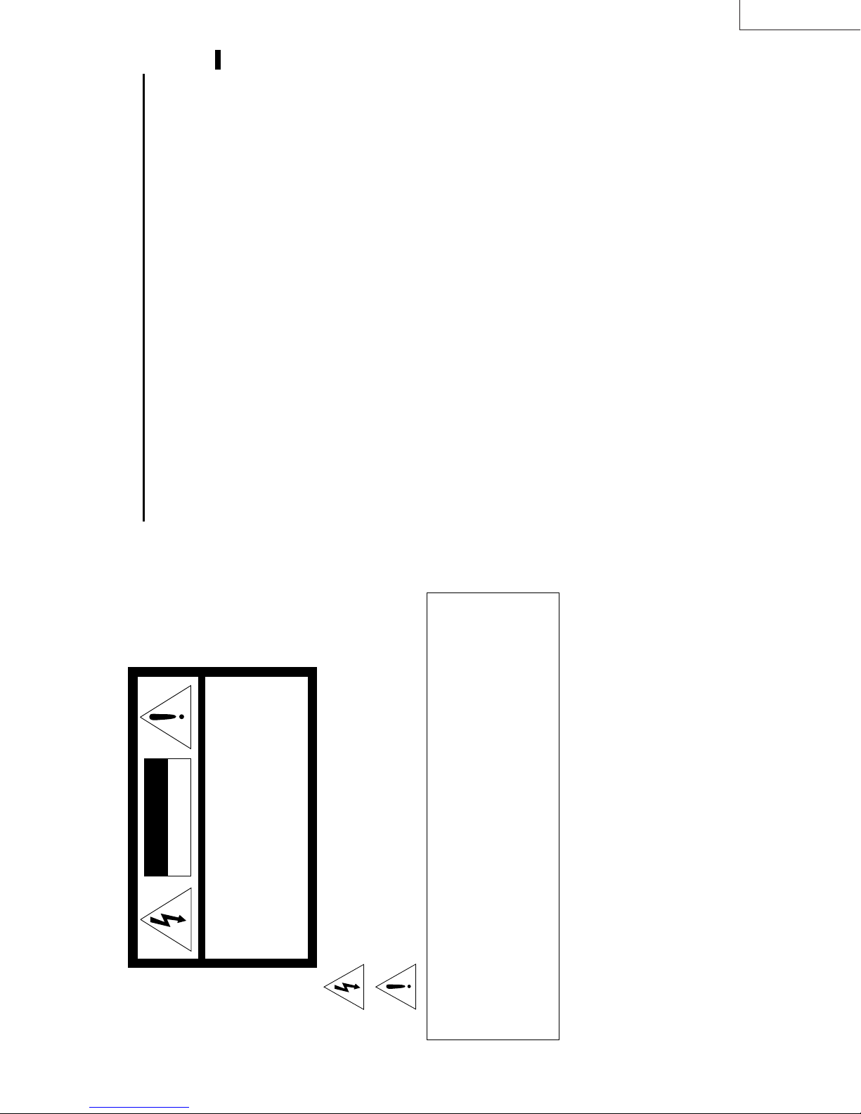
The lightning flash with arrowhead symbol, within an equilateral triangle, is intended
to alert the user to the presence of uninsulated “dangerous voltage” within the
product’s enclosure that may be of sufficient magnitude to constitute a risk of electric
shock.
The exclamation point within an equilateral triangle is intended to alert the user to the
presence of important operating and maintenance (servicing) instructions in the litera-
ture accompanying the appliance.
WARNING:
TO PREVENT FIRE OR SHOCK HAZARD, DO NOT EXPOSE THIS APPLIANCE TO RAIN OR MOISTURE.
CAUTION:
TO PREVENT ELECTRIC SHOCK, DO NOT USE THIS (POLARIZED) PLUG WITH AN EXTENSION
CORD, RECEPTACLE OR OTHER OUTLET UNLESS THE BLADES CAN BE FULLY INSERTED TO
PREVENT BLADE EXPOSURE.
NOTE:
SINCE THIS PROJECTOR IS PLUGGABLE EQUIPMENT , THE SOCKET-OUTLET SHALL BE IN-
STALLED NEAR THE EQUIPMENT AND SHALL BE EASILY ACCESSIBLE.
WARNING
Use the attached specified power supply cord. If you
use another power-supply cord, it may cause interfer-
ence with radio and television reception.
Use the attached RGB cable, RS-232C cable with this
equipment so as to keep interference within the limit
of a FCC Class A device.
This apparatus must be grounded.
The projector automatically shuts off when the
lamp is used up in about 2,000 hours and cannot
be used until lamp replacement.
DO NOT LOOK DIRECTLY INTO THE LENS
WHEN PROJECTOR IS IN THE POWER ON
MODE.
EN – 2
Page 6
LX-D1010G
Do not turn off the main power
ENGLISH
+95°F (+35°C)
abruptly or unplug the projector
during operation.
It can lead to lamp breakage, fire, electric shock or
other trouble. It is best to wait for the fan to turn off
before turning main power off.
Place of installation
For safety’s sake, refrain from setting the projector at
any place subjected to high temperature and high
humidity. Please maintain an operating temperature,
humidity, and altitude as specified below.
jector so that the projector does not overheat.
• Operating temperature: between +41°F (+5°C) and
• Operating humidity: between 30 and 90%
• Never put any heat-producing device under the pro-
stable or subject to vibration.
produces a strong magnetic field. Also refrain from
installing near the projector any cable carrying a
large current.
face: otherwise it may fall, causing serious injury
to a child or adult, and serious damage to the prod-
• Do not attach the projector to a place that is un-
• Do not install the projector near any equipment that
uct.
• Place the projector on a solid, vibration free sur-
ous injury and damage to the projector.
the projector more than ±15˚ may cause trouble or
explosion of the lamp.
• Do not stand the projector: it may fall, causing seri-
• Place the projector within a slope of ±15˚. Slanting
• Do not place the projector near air-conditioning unit
or heater to avoid hot air to the exhaust and venti-
lation hole of the projector.
EN – 5
WARNING:
Unplug immediately if there is
something wrong with your projector.
Do not operate if smoke, strange noise or odor comes
out of your projector. It might cause fire or electric
shock. In this case, unplug immediately and contact
your dealer.
Never remove the cabinet.
This projector contains high voltage circuitry. An
inadvertent contact may result in an electric shock.
Except as specifically explained in the Owner's
Guide, do not attempt to service this product
yourself. Please contact your dealer when you want
to fix, adjust or inspect the projector.
Do not modify this equipment.
This projector should be operated only from the
type of power source indicated on the marking
label. If you are not sure of the type of power,
please consult your appliance dealer or local
power company.
Power-supply cords should be routed so that they
are not likely to be walked on or pinched by items
placed upon or against them. Pay particular at-
tention to cords at plugs, convenience receptacles,
and points where they exit from the appliance.
Do not overload wall outlets and extension cords
as this can result in a fire or electric shock.
Never push objects of any kind through open-
10. Power sources
11. Power-cord protection
12. Overloading
13. Objects and liquids
It can lead to fire or electric shock.
If you break or drop the cabinet.
Do not keep using this equipment if you break or
drop it. Unplug the projector and contact your dealer
for inspection. It may lead to fire if you keep using
the equipment.
Do not face the projector lens to the
sun.
It can lead to fire.
Use correct voltage.
If you use incorrect voltage, it can lead to fire.
Do not place the projector on uneven
surface.
Place the projection on a leveled and stable surface
aged.
fallen into the projector.
ings of this projector as they may touch danger-
ous voltage points or short-out parts that could
result in a fire or electric shock. Never spill liq-
uid of any kind on the projector.
Do not attempt to service this projector yourself.
Refer all servicing to qualified service person-
nel.
Unplug this projector from the wall outlet and
refer servicing to qualified service personnel un-
der the following conditions:
(a) If the power-supply cord or plug is dam-
(b) If liquid has been spilled, or objects have
(c) If the projector does not operate normally
14. Servicing
15. Damage requiring service
COMPLIANCE NOTICE OF FCC
This equipment has been tested and found to comply with the limits for a Class A digital device, pursu-
ant to Part 15 of the FCC Rules. These limits are designed to provide reasonable protection against
harmful interference when the equipment is operated in a commercial environment. This equipment
generates, uses, and can radiate radio frequency energy and, if not installed and used in accordance
with the instruction manual, may cause harmful interference to radio communications. Operation of
this equipment in a residential area is likely to cause harmful interference in which case the user will
be required to correct the interference at his own expense.
This digital apparatus does not exceed the Class A limits for radio noise emissions from digital appara-
only. Please do not place equipment on unstable
surfaces.
Do not look into the lens when it is operating. It may
hurt your eyes.
Never let children look into the lens when it is on.
after you follow the operating instructions.
Adjust only those controls that are covered
by the operating instructions. An improper
adjustment of other controls may result
in damage and may often require exten-
sive work by a qualified technician to re-
store the projector to its normal operation.
or water.
cabinet has been damaged.
in performance - this indicates a need for
service.
(d) If the projector has been exposed to rain
(e) If the projector has been dropped or the
(f) If the projector exhibits a distinct change
When replacement parts are required, be sure
that the service technician has used replacement
parts specified by the manufacturer or parts
having the same characteristics as the original
16. Replacement parts
tus as set out in the interference-causing equipment standard entitled “Digital Apparatus”, ICES-003 of
the Department of Communications.
Changes or modifications not expressly approved by JVC could void the user's authority to operate this
equipment.
COMPLIANCE NOTICE OF INDUSTRY CANADA
This Class A digital apparatus complies with Canadian ICES-003.
part. Unauthorized substitutions may result in
fire, electric shock or other hazards.
Upon completion of any service or repair to this
projector, ask the service technician to perform
safety checks determining that the projector is
in a safe operating condition.
17. Safety check
All the safety and operating instructions should
The safety and operating instructions should be
All warnings on the appliance and in the oper-
All operating instructions must be followed.
be read before the appliance is operated.
retained for future reference.
ating instructions should be adhered to.
Important safeguards
Please read all these instructions regarding your LCD
projector and retain them for future reference. Follow
all warnings and instructions marked on the LCD pro-
jector.
1. Read instructions
2. Retain instructions
3. Warnings
Unplug this projector from the wall outlet be-
4. Instructions
5. Cleaning
fore cleaning it. Do not use liquid aerosol clean-
Never add any attachments and/or equipment
ers. Use a damp soft cloth for cleaning.
without the approval of the manufacturer as
6. Attachments and equipment
such additions may result in the risk of fire, elec-
tric shock or other personal injury.
7. Water and moisture
Do not use this projector near water or in con-
Do not place this projector on an unstable cart,
tact with water.
stand, tripod, bracket or table. Use only with a
cart, stand, tripod bracket, or table recommended
by the manufacturer or sold with the projector.
8. Accessories
An appliance and cart combination should be
Any mounting of the appliance should follow the
manufacturer's instructions and should use a
mounting accessory recommended by the manu-
facturer.
moved with care. Quick stops, excessive force and
Slots and openings in the cabinet are provided
uneven surfaces may cause the appliance and
cart combination to overturn.
for ventilation, ensuring reliable operation of the
projector and to protect it from overheating. Do
not block these openings or allow them to be
blocked by placing the projector on a bed, sofa,
rug, or bookcase. Ensure that there is adequate
ventilation and that the manufacturer's instruc-
9. Ventilation
tions have been adhered to.
EN – 4
Page 7
ENGLISH
CAUTION
WAVE LENGTH : 640 - 660 nm
MAX OUTPUT : 1 mW
CLASS 2 LASER PRODUCT
LASER RADIATION
IEC 60825-1:1993+A1:1997
DO NOT STARE INTO BEAM
LX-D1010G
EN – 7
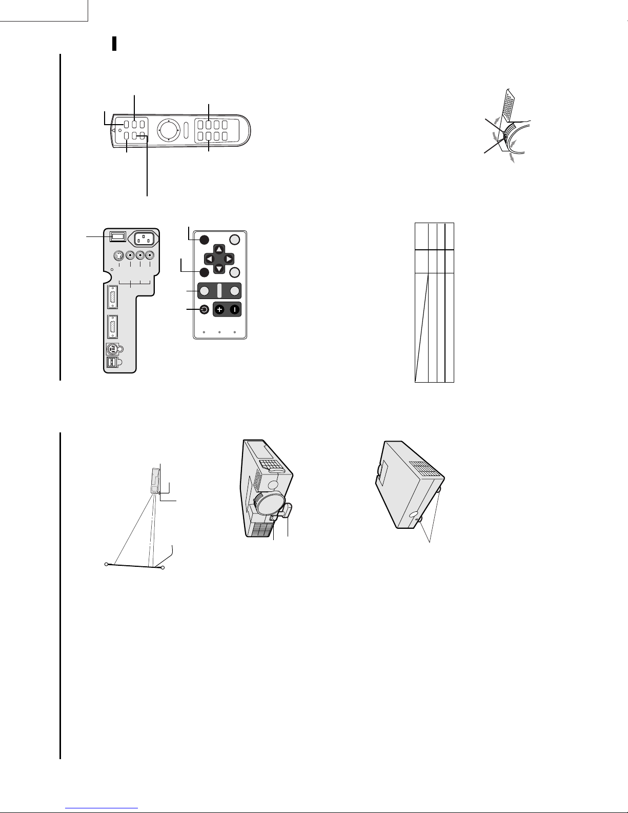
1 Adjustment foot (right and left)
2 Lamp cover
3 Adjustment foot (up and down)
Caution:
Do not replace the lamp right after using the projector. The
lamp is very hot.
3
2
Bottom side
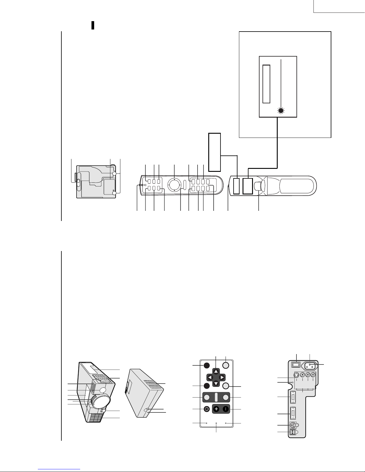
1 Transmitter indicator
2 POWER button
3 COMPUTER button
4 MOUSE button
5 Right click button (For mouse)
6 MENU button
1
16
POWER HIDE
1
2
Remote control
STILL button
2 ENTER button
13 Mouse pointer / Direction button
14 LASER button
15 VIDEO button
7 AUTO POSITION button
8 PinP button
9 + , – (VOLUME) buttons
10 EXPAND button
11
14
15
VIDEO
MOUSE LASER
COMPUTER
3
4
1
13
16 HIDE button
12
R-CLICK
MENU ENTER
5
6
Direction button work as the mouse pointer. Press
the MOUSE button or MENU button to set off.
(Direction button work as Direction button.)
1 minute. Release LASER button and press it again
if you wish to emits the laser beam.
17 Laser aperture
18 Left click button (For mouse)
• When pressing MOUSE button, it illuminates and
• Pressing LASER button emits the laser beam about
About laser beam
Beam Divergence : 3 m distance about 5.0 mm x 3.0 mm (±1.5 mm)
640 - 660 nm) laser equipment.
This remote control is class 2 (max. output 1 mW laser diode
18
11
STILL
AUTO POSITION
7
P in P EXPAND
LASER
10
AVOID EXPOSURE -
RADIATION IS EMITTED
FROM THIS APERTURE.
VOLUME–+
9
8
17
laser beam. Do not look into the beam light directly . Do not
point the laser beam at people. Looking the laser beam directly
may damage eyesight.
CAUTION :
• Pressing the LASER button provided remote control emits
specified herein may result in hazardous radiation exposure.
• Use of controls or adjustments or procedures other than those
connector
1 Air inlet grill (Front)
2 Front height adjuster button
3 Air inlet grill (Side)
4 Terminal board
5 Speaker
6 Remote control sensor (Front)
7 Control panel
8 Zoom ring
9 Focus ring
10 Lens
11 Kensington Security Lock Standard
56710
8
9
314
2
Overview
12 Remote control sensor (Rear)
13 Air outlet grill
13
12
11
1 LAMP indicator
2 TEMP (temperature) indicator
3 + , – (VOLUME) buttons
4 VIDEO button
5 MENU button
6 ENTER button
7 Direction buttons
8 HIDE button
9 AUTO POSITION button
7
89101112
HIDE
AUTO POSITION
SOURCE
COMPUTER
POWER
LAMP
1
Control panel
POWER button
12 POWER indicator
10 COMPUTER button
11
6
ENTER
MENU
VIDEO
VOLUME
TEMP
2345
I : ON
O : OFF
1 Ground terminal
2 Power jack
3 Main power
4 Video/audio input terminals
5 Reset button
456789
Terminal board
6 COMPUTER IN terminal (D-SUB mini 15P)
7 COMPUTER OUT terminal (D-SUB mini 15P)
8 RS-232C (DIN 8P) terminal
9 USB terminal
2
3
O
I
MAIN
S-VIDEO
COMPUTER INCOMPUTER OUT
RS-232CUSB
VIDEO
VIDEO IN
AUDIO L
(MONO)
1
AC IN
AUDIO R
EN – 6
Page 8
LX-D1010G
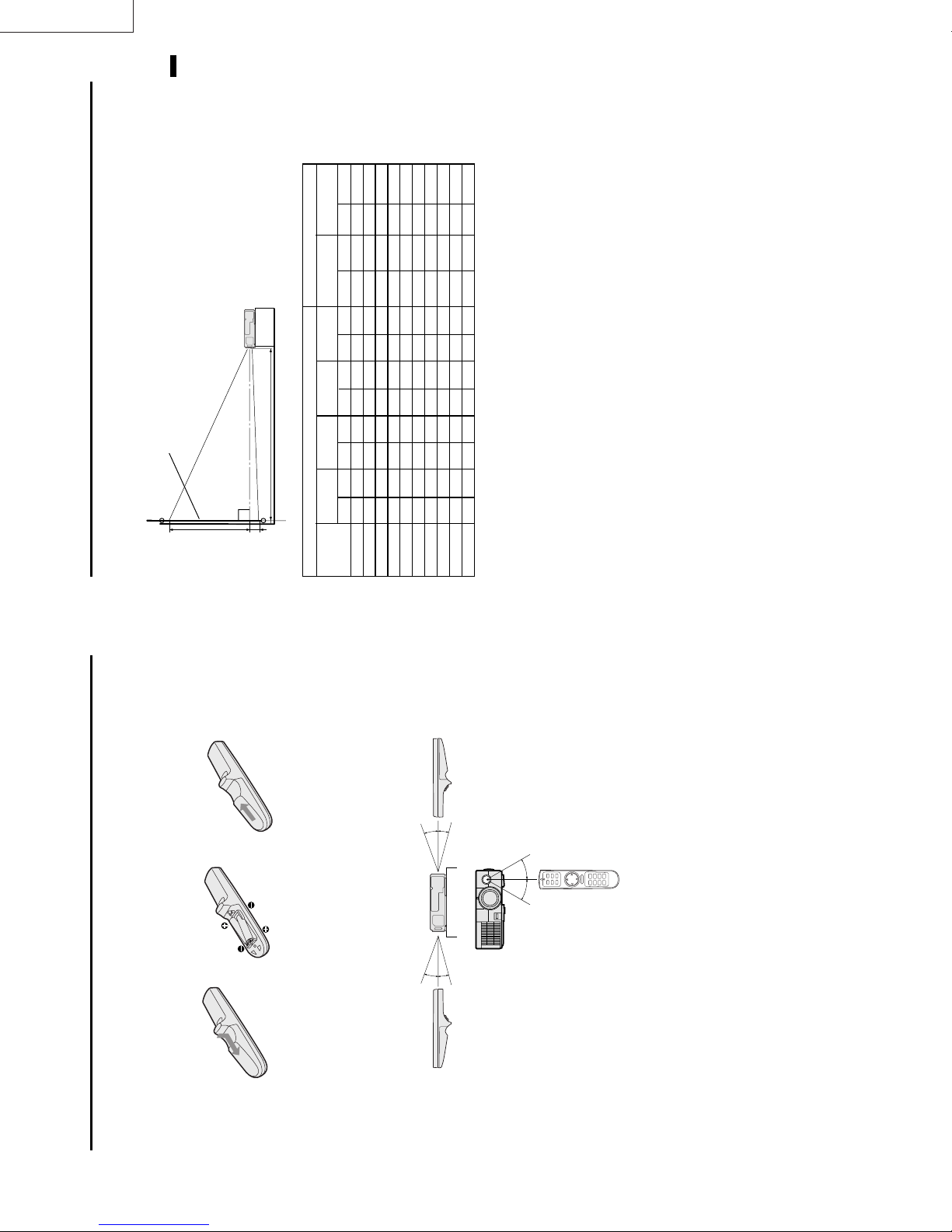
Installation
Orientation of the projector
1.7 (min.) , Multiply the width of the
To find the approximate distance be-
tween the projector and screen:
Multiply the width of the screen
×
screen
Picture size can be set by changing the distance between the screen and the projector.
Front projection
ENGLISH
2.4 (max.).
×
distances in maximum zoom and
minimum zoom.
screen
• Refer to the chart for recommended
(between the screen and
L
the head of the projector)
BA
72 "
110 "
147 "
184
55 "
140
2.4"
6.1
21.6 "
54.9
32 "
81
24 "
61
40 "
279
84 "
213
3.6"
9.1
32.4 "
81.9
48 "
122
36 "
91
60 "
374
113 "
286
4.8"
12.2
43.2"
109.8
64 "
163
48 "
122
80 "
185 "
469
142 "
360
6.0"
15.2
54.0"
136.8
80 "
203
60 "
152
100 "
(inch)
Minimum
zoom (TELE)
(cm)
(inch)
Distance from screen (L)
Maximum
(cm)
zoom (WIDE)
(inch)
(cm)
(inch)
AB
(cm)
(inch)
Screen
(cm)
(inch)
Height Width
(cm)
(inch)
Diagonal size
222 "
564
171 "
433
7.2"
18.3
64.8"
164.7
96 "
244
72 "
183
120 "
259 "
659
199 "
506
8.4"
21.3
75.6"
191.7
112 "
284
84 "
213
140 "
297 "
754
228 "
579
9.6"
24.4
86.4 "
219.6
128 "
325
96 "
244
160 "
334 "
372 "
548 "
849
944
1393
257 "
285 "
421 "
652
725
10.8"
27.4
97.2"
246.6
144 "
366
108 "
274
180"
1070
12.0"
18.0"
30.5
45.7
108.0"
162.0"
411.3
274.5
160 "
240 "
406
610
120 "
180 "
305
457
200 "
300 "
• Do not use the projector under the following
Rear projection
• The above numbers are approximate, and may be slightly different from the actual measurements.
Ceiling mount,
down
circumstances, which may cause fire or electric
shock.
• in a dusty or humid place
• while the projector is lying sideways or upside
• near a heater
Ask a specialist for installation. For more details,
consult your dealer.
Caution:
• Placing the projector on a carpet reduces ventila-
higher than 95 °F
• in a kitchen or oily, smoky or damp place
• in direct sunlight
• with high temperature, such as the closed car
tion from the fan at the bottom and might cause
problems. Place a hard board or similar item
under the projector to facilitate ventilation of the
• where the temperature is lower than 41 °F or
unit.
damage.
Important:
• Do not add stress on the lens, as this may cause
from the wall to prevent blocking the intake,
exhaust slots and ventilation of this projector
because hot air comes out of it.
• Place the projector more than 50 cm (20 inches)
´ EN – 9
12 3
arrow.
Using the remote control
Battery installation
Use two AAA size batteries.
• Load the batteries from - spring side, and make sure to set them tightly.
1. Remove the back cover of the remote control by pushing the battery compartment door in the direction of the
2. Load the batteries making sure that they are positioned correctly (+ to +, and - to -).
3. Replace the back cover.
Important:
• Do not combine a new battery with an old one.
• Load batteries in the correct position.
20˚
15˚
30˚30˚
20˚
15˚
in contact with your eyes, rinse them with water and then consult your doctor.
• Do not heat, take apart, or throw batteries into fire.
• Do not try to recharge batteries. Do not use rechargeable batteries.
• If the solution of batteries comes in contact with your skin or clothes, rinse with water. If the solution comes
Operation area
The range for operation is about 10 m (33 feet) when the remote control points to the projector. The distance to
the screen back to the projector must be less than 6 m (20 feet). Depending on the type of the screen, the distance
is different.
Important:
Avoid the direct sunlight or fluorescent light to the remote control sensor. Also keep the distance of more than 2 m
between the remote control sensor and fluorescent lamp on the remote control may not work correctly.
EN – 8
Page 9
ENGLISH
LX-D1010G
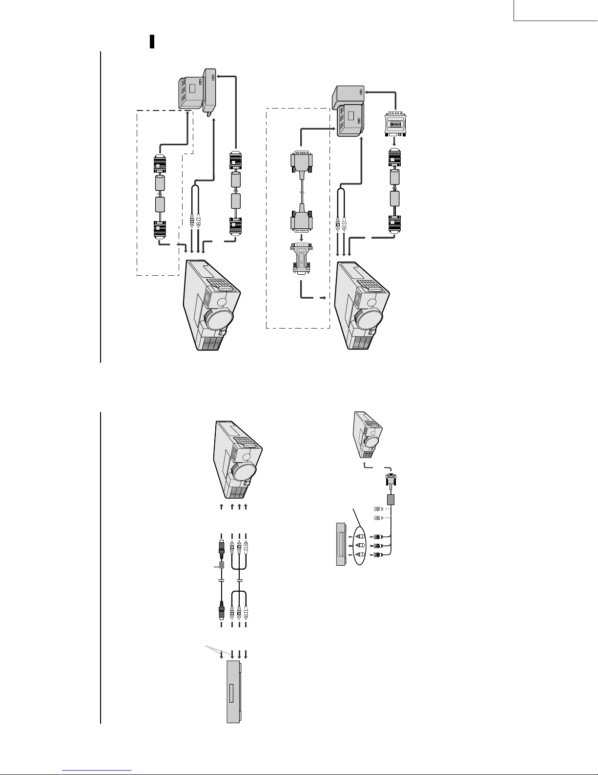
to video port
computer
to PC
monitor
to PC audio
output
RGB cable for PC
(optional)
PC audio cable
(optional)
to AUDIO IN
When outputting to both a PC monitor and the projector.
Connection
For IBM PC or IBM PC compatibles
Projector + Personal computer
to COMPUTER OUT
to monitor
port
IN
to COMPUTER
to PC
monitor
to PC audio
output
Monitor cable
(optional)
RGB cable for PC
PC audio
cable (optional)
to AUDIO IN
Monitor Conversion
adapter (optional)
When outputting to both a PC monitor and the projector.
to COMPUTER OUT
For Macintosh
ON DIP
1 2 3 4 5 6
computer
to COMPUTER IN
MAC adapter for
RGB cable (Optional)
RGB cable for PC
Please contact your dealer.
cable for the audio input terminal of the PC. Some personal computer may not have the audio output terminal.
Important:
• Connectors or analog RGB output adapters may be necessary depending on the PC connected to this projector.
• The audio input for this projector is a stereo pin jack. (Speaker output is mono.) Please check the available
L terminal.
• Select AUDIO MODE 1 to hear and to sound for the COMPUTER. (Refer to page 16).
• When connecting audio output of a personal computer which audio output is mono, connect to the audio input
tor. Please contact your dealer.
For using Macintosh
• A monitor output adapter is necessary for a Macintosh if it has no video port. Please contact your dealer.
• A MAC adapter for RGB cable may be necessary depending on the personal computer connected to this projec-
´ EN – 11
input
input
input
to video
to audio
to S-video
Ferrite core
Connect either one of these.
output
output
output
to video
to audio
to S-video
). When connecting them to the projector,
R
, C
B
” for COMPUTER INPUT setting in SIGNAL
R
, C
B
DVD player or HDTV decoder
) ter-
R
, P
B
) terminals. HDTV decoder has
R
, C
B
VCR etc.
the same time, the normal video input automatically is inhibited.
Basic connections
This projector can be connected to equipment such as PC, VCRs, video cameras and DVD players.
Important:
• Make sure that your equipment is turned off before connection.
• Plug in firmly and unplug by holding the plug, not by pulling the AC power cord.
• If connected units are set too close to one another, the image may be affected.
• Refer to the user manual of each component for details of connections.
Projector + AV equipment
Important:
• Match the color of video and audio plugs on the AV cable with the connections.
• S-video signals take priority over video signals. If you input both S-video signals and normal video signals at
• Speaker output is mono.
• Select AUDIO MODE 2 to hear and to sound for the VIDEO. (Refer to page 16).
• When connecting audio output of equipment which audio output is mono, connect to audio input L terminal.
Projector + DVD player or HDTV decoder
Some DVD players have output terminal for 3 line fitting (Y, C
menu.
DVD player generally has SDTV system component
video output (Y, C
connect to COMPUTER IN of the projector. In this case, set “ Y, C
HDTV system component video output (Y, P
BNC-RCA connector
(optional)
)
R
(P
R
)Y C
B
(P
B
C
In this case,
.
the COMPUTER INPUT in the SIGNAL menu becomes
minals. When connecting the projector with DVD
player or HDTV decoder, the signal cuircuit
automaticaly applied to either of them
IN
to COMPUTER
No connection
HD/CS VD
BG R
].
R
, P
B
/Y, P
R
, C
B
[Y, C
Mini D-SUB 15 pin-BNC
conversion cable (optional)
is an example of the terminal names for
R
, P
B
a HDTV decoder.
• The terminal name is different depending on the connected equipment.
•Y, P
the SIGNAL setting menu.
• Use mini D-SUB 15 pin-BNC conversion cable for connection.
• Some DVD players may not project the image correctly.
• When connecting with HDTV equipment which has R, G, B output, set RGB for the COMPUTER INPUT in
• Change the setting in the SIGNAL menu, when 525p signal is inputted. (Refer to page 20).
EN – 10
Page 10
LX-D1010G
ENGLISH
4
HIDE button
VIDEO
MOUSE LASER
POWER HIDE
COMPUTER
3 • 7 • 8
4
O
I
2 • 9
MAIN
S-VIDEO
COMPUTER INCOMPUTER OUT
RS-232CUSB
VIDEO
VIDEO IN
AUDIO L
(MONO)
AC IN
AUDIO R
To operate projector power ON
STILL
R-CLICK
MENU ENTER
AUTO POSITION
HIDE button
HIDE
AUTO POSITION button
AUTO POSITION
POWER
3 • 7 • 8 4
STILL button
VOLUME– +
P in P EXPAND
AUTO POSITION
button
ENTER
MENU
VIDEO
SOURCE
COMPUTER
VOLUME
LAMP
TEMP
lamp should be replaced. Replace the lamp. See
pages 23 and 26.
• When the lamp indicator is blinking red, the the
• The picture might not be of optimum performance
main power switch. The POWER indicator lights up
1. Turn on the equipment connected to the projector.
2. Put the projector into standby mode by pressing the
in extreme hot or cold conditions. (The projector is
not malfunctioning.)
the COMPUTER or VIDEO button.
4. Select the desired external input source by using
seconds after the power switch ON. In this
time, the buttons will not work.
red.
• The POWER indicator blinks red for 2, 3
when MENU is displayed.
signal format. The selected signal format is dis-
played on the screen.
may flicker. Press the $ or % button to adjust the
image.
or % button also connecting with DVD player or
MUSE decoder etc.
Reverse play with VCR, “NO SIGNAL” may
appear on the screen. In this case, you may avoid
this issue by selecting the right color format like
• The COMPUTER or VIDEO buttons do not work
• The projector automatically selects the appropriate
• When selecting the COMPUTER input, the image
• When input signal is jittering, please adjust by $
NTSC, PAL in OPTION menu.
• When supplying unstable signal like Still or
Red
POWER
-
LAMP
5. Adjust the image size with the zoom ring by turn-
Red
Green
-
Green
Indicator
Stand-by
off within two minutes of turning off the light
source lamp, power will not be applied to the
lamp for one minute when the next time the
main unit power switch is turned on. When
this happens, the indicator lamp will blink for
The light source lamp starts warming up, eventu-
ally turning completely on. In case the light source
lamp does not come on, wait for one minute before
switching power on again.
• If the main power switch to the unit is turned
3. Turn the projector on by pressing the POWER button.
one minute.
When light source lamp is on
Condition
Light source lamp held off temporarily
ing it.
6. Adjust the focus with the focus ring by turning it.
the POWER button due to warming up of this pro-
Important:
• A darkened image may be seen right after pressing
wide
zoom ring
tele
focus ring
jector. While warming up, no other commands can
be accepted.
far
near
´ EN – 13
Adjustment foot
screen
low the adjustment foot (up and down) to slide out
to the position.
into the outlet, contact your electrician to replace
your A/C outlet.
3. Release the Front height adjuster button to lock the
only. Never connect to any outlet or power supply
• The supplied power cord for U.S. is used for 120V
feet in that position.
having a different voltage or frequency. If you
connect to the power supply having a different
voltage, please use the appropriate power cord.
• Use 100-240V AC 50/60Hz correct voltage other-
Adjusting the angle of projection
For the best result, project onto a flat screen with a 90
degree angle to the floor. If necessary, tilt the projector
by adjusting two foot adjustments on the bottom of the
projector.
“ON”.
the power on with the cap on, the cap may be warped.
Please remove the lens cap when you turn the power
Preparing the projector for operation
Getting ready for projection
1. Connect the power cord provided to the projector.
2. Connect the power cord to the wall power outlet.
3. Remove the lens cap.
Warning:
• Do not look directly into the lens when projector is
on.
• The lens cap is for protecting the lens. If you leave
• This projector is equipped with the power cords for
both U.S. and Europe. Use the appropriate power
cord for your country.
1. Lift the projector to the appropriate angle.
the projector. Do not remove the grounding pin on
• A three-pin grounding type power plug is used with
2. Press the Front height adjuster button, this will al-
the power plug. If you are unable to insert the plug
projector by pressing the Front height adjuster but-
After using the projector
may cause fire or electric shock.
Contact your dealer if the cord is broken.
ton.
4. Return the adjustment foot (up and down) into the
When the left and right angles are different
Adjust the angles with adjustment feet (right and left),
which are on the bottom of the projector.
by pulling the cable out.
• Plug in firmly and unplug by holding the plug, not
an electric shock.
• Do not plug in or out with wet hands. It may cause
Caution:
(up and down)
Adjustment foot
Release button
wise it may lead to fire or electric shock.
the projector away from heat sources to avoid break-
ing the power cord. A broken power cord can cause
fire or electric shock.
• Do not place any objects on the power cord, and keep
• Do not revise or alter the power cord otherwise it
(right and left)
Adjustment foot
illustrated on page 9.
Important:
• Screen on a flat wall with a 90˚ angle to the floor.
• Align projector to produce a full screen display as
• The distance from the projector to the screen must
be compatible with screen size chart on page 9.
Note the distance from the screen chart.
EN – 12
Page 11

ENGLISH
***
LX-D1010G
EN – 15
*
± 10
RED ± 10
BLUE ± 10
CYAN ± 10
GREEN ± 10
YELLOW ± 10
MAGENTA
CONTRAST B ± 30
CONTRAST R ± 30
BRIGHTNESS B ± 30
BRIGHTNESS R ± 30
1
3
2
OFF
LOW
HIGH
USER
USER
BRIGHTNESS ± 30
COLOR MATRIX
IMAGE CONTRAST ± 30
STANDARD
COLOR TEMP .
USER
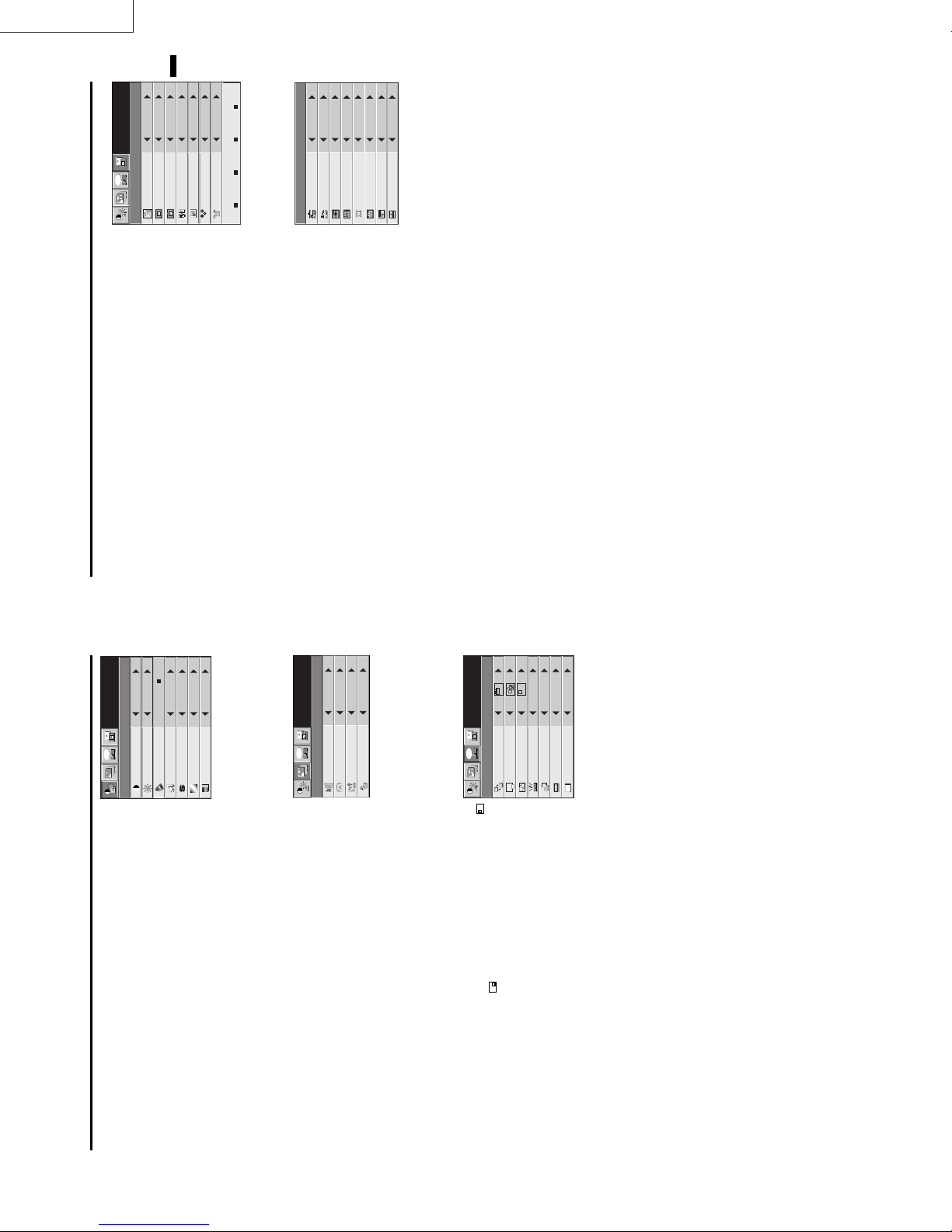
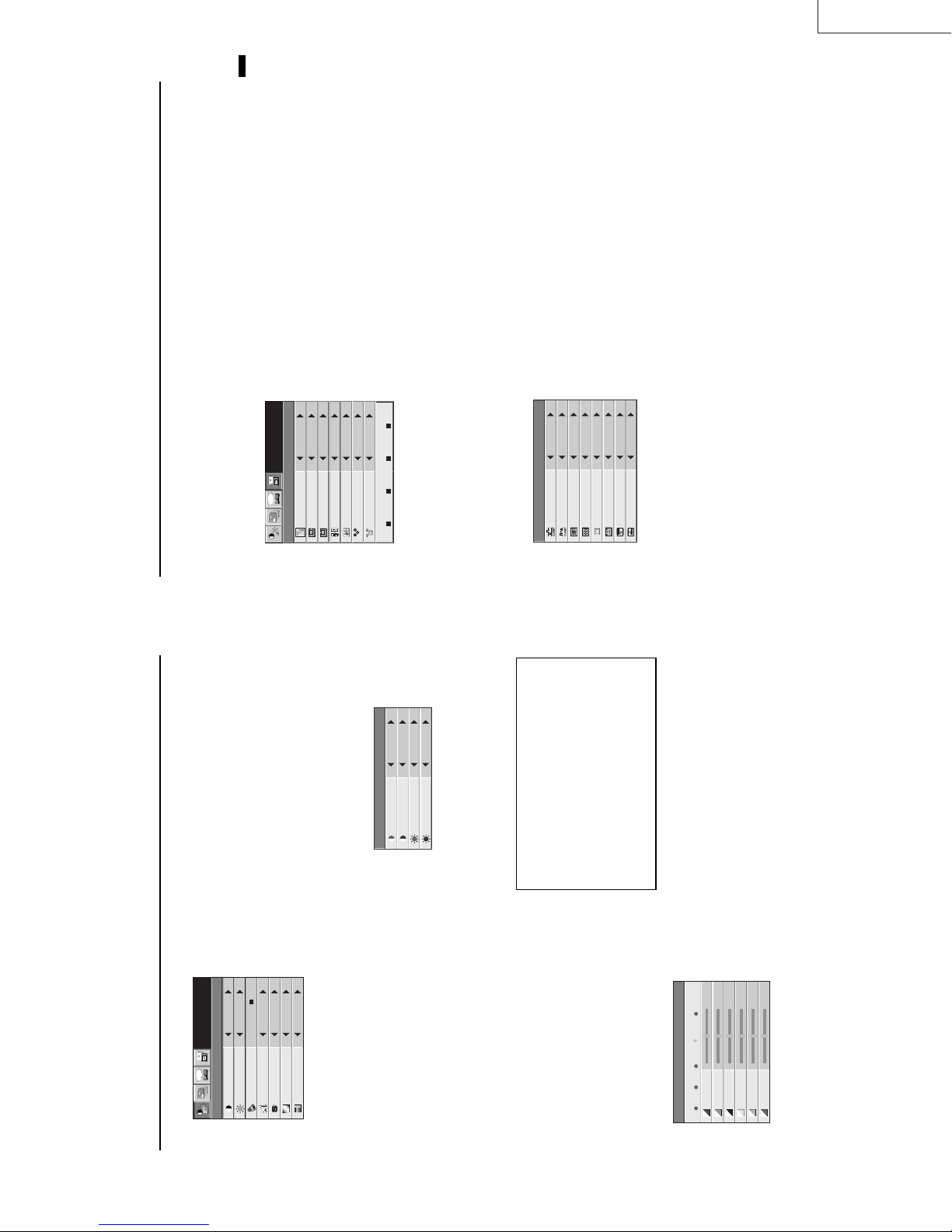
Menu operation
SHARPNESS ± 10
(Displays only when the source is selected to VIDEO)
(Displays only when the source is selected to VIDEO)
TINT ± 10
COLOR ± 10
KEYSTONE ± 15˚
AUTO POWER ON ON, OFF
INSTALLATION IMAGE REVERSE OFF, MIRROR, INVERT, MIRROR INVERT
(When the signal from the COMPUTER IN terminal
is inputted, the setting is fixed to AUTO.)
1 - 3
OFF, 5, 10, 15, 30, 60 min
AUTO POWER OFF
AUTO, NTSC, PAL, SECAM, 4.43NTSC, PAL-M, PAL-N, PAL-60
1=Upper left, 2=Lower right
AUDIO MODE
VIDEO SIGNAL
EXPAND MODE 1 - 4
FRAME POSITION 1 - 5
FEATURES MENU POSITION
* : Setting range is different
according to the type of
the signal.
***
FINE SYNC. 0 - 39
VERT.POSITION 0 - 999
HORIZ.POSITION 0 - 999
SIGNAL MEMORY CALL AUTO, USER1, USER2
0 - 9999
TRACKING
ON, OFF
日本語, English, Español, Deutsch, Français, Italiano, 中文
LANGUAGE
ANAMORPHIC
0 - 383
0 - 383
AUTO, ON, OFF
AUTO, 0 - 7
CLAMP POSITION 0 - +63
USER
CLAMP WIDTH 0 - +63
VERT LINES 0 - 9999
HORIZ. PIXELS 0 - 9999
USER2
USER2
,
,
USER1
USER1
DELETE
DEFAULT
MEMORIZE
PLL
VERT. SYNC
KEYSTONE 0˚
SHUTTER (L)
SHUTTER (U)
OFF.
4. Press the { or } button to select AUTO POWER
Basic operation
Several settings can be adjusted using Menu.
AUTOPOWERON OFF
AUTOPOWEROFF OFF
EXAMPLE:Auto power off time setting
time.
5. Press the $ or % button to adjust auto power off
Opt
1. Press the MENU button.
KEYSTONE 0˚
AUTOPOWERON OFF
XGA60
IMAGE
AUTOPOWEROFF 30min
6. Exit the menu system by pressing the MENU but-
TION menu.
2. Press the $ or % button to select the INSTALLA-
ton several times.
• If the menu operation is not working, press the
XGA60
Opt
INSTALLATION
RESET button on the terminal board using the suit-
able implement
• If the COMPUTER or VIDEO button is pressed, the
XGA60
Opt
3. Press the ENTER button (or } button).
MENU selection bar or MENU will disappear.
ENTER button after selecting.
• The settings with 2 mark, you should press the
OFF
IMAGEREVERSE
KEYSTONE 0˚
AUTOPOWERON OFF
INSTALLATION
AUTOPOWEROFF OFF
END 1 - 99
BEGIN -1 - -99
R
P
B
/ YP
R
C
B
ON
OFF
HOLD AUTO
COMPUTER INPUT RGB, YC
seconds after releasing the volume buttons.
selection bar or MENU is displayed.
• The volume control bar will disappear about 4
changed.
• The volume buttons do not work when MENU
• The volume from the audio output terminals are not
AV HIDE
POWER, LASER, mouse pointer, R/L-click,
STILL and VOLUME + and - buttons.
The message “POWER OFF? YES : PRESS AGAIN”
• To exit from this mode, press any button except
appears on the screen.
Turning off the projector
7. Press the POWER button.
To operate projector power ON (Continue)
8. Press the POWER button again.
audio will be restored automatically to the normal
Image and audio are temporarily erased with press-
ing the HIDE button . To restore the image and audio
to the normal mode, press the HIDE button again.
• To prevent the damage of the LCD, the image and
The light source lamp will be turned off.
Pressing the POWER button second time will shut
off the light source lamp, but the exhaust fan con-
tinues to operate for 60 seconds to cool down the
light source lamp and LCD panels. In this time, the
mode, 10 minutes after setting the AV HIDE mode.
60 seconds for the exhaust fans to stop. Then turn off
the main switch and unplug the power cable from the
wall outlet, for safety purposes.
switched on again for 60 seconds as a precaution-
ary measure. It will take another 60 seconds before
the lamp indicator goes off. If you wish to turn on
the projector again, wait until the indicator is off
then press the POWER button.
ture around the projector rises.
Caution:
• When you have finished using this equipment, wait
• After the lamp is turned off, the lamp cannot be
tally turned off when either the intake/exhaust
fan or the power source lamp is in operation, allow
the unit to cool down for 10 minutes with the
power turned off. Repeat step 3 when turning on
the power source lamp. If the lamp does not turn
the main switch, the POWER indicator turns off.
lamp indicator will be turned off.
9. Turn off the main power switch. When turning off
• In cases where the main power switch is acciden-
on immediately, repeat this step two or three
too high, the sign “TEMP!!” blinks red on the screen.
• The exhaust fan rotates faster when the tempera-
• When the temperature around the projector becomes
times. Replace the lamp if it should still fail to
turn on.
AUTO POSITION button
If the temperature stays too high, the lamp will be
shut off automatically .
The projector automatically shuts off when the
lamp is used up in about 2000 hours. You must
replace the lamp.
(e.g., full-screen display of the “Trash” window)
before deploying the automatic adjustment func-
tion.
saver before using the automatic adjustment
When the source is selected to COMPUTER and the
button.
image is not in the right place, set the screen to the
brightest display possible, then press the AUTO
POSITION button on the remote control. If the image
is still not in the right place.
• Set screen to the brightest display as possible
• If the screen saver is running, turn off the screen
terminal.
setting of AUDIO MODE in the FEATURE menu.
The sound from the speaker
The sound from the speaker is mono.
See page 16 for details.
• When inputting mono sound, connect to AUDIO L
• The output sound is selected by changing the
30
The volume from the speaker
Press the volume + or – button to change the volume
from the speaker.
The volume control bar will appear on the screen.
EN – 14
Page 12
LX-D1010G
ENGLISH
AUTO
XGA60
Opt
MEMORYCALL
HORIZ.POSITION 208
VERT.POSITION 22
TRACKING 1056
COMPUTERINPUT RGB
FINESYNC. 24
HOLD AUTO
The unit adjusts itself automatically when connected to
COMPUTER INPUT ....
RGB
RGB
) or equipment with HDTV
R
P
B,
or Y, P
R
C
B,
either DVD players with a component video output
terminal (Y, C
USER MEMORIZE DEL ETE DEFAULT
signal output capabilities. In cases where the unit is
connected to equipment that include an RGB output
terminal and which output HDTV signals, adjust the unit
SIGNAL−USER
to RGB mode.
CLAMP POSITION/
HOLD .................. Adjusts the image when curving near the top.
5 SIGNAL - USER (Normally, there is no need for adjustments.)
U
A
SIGNAL
Use to select AUTO, USER 1 or USER 2. See below.
Use to adjust the horizontal position of the image.
Use to adjust the vertical position of the image.
that the image is not blurred.
MEMORY CALL ........
HORIZ. POSITION ....
VERT. POSITION .....
FINE SYNC. ....... Use to synchronize the projector with PC input signals so
TRACKING ......... Use to avoid image noise such as wide stripes.
4 SIGNAL
0
CLAMPPOSITION
CLAMPWIDTH +5
HORIZ.PIXELS 800
PLL AUTO
SHUTTER(L) 0
VERT.LINES 600
VERT.SYNC. AUTO
SHUTTER(U) 0
?
If you use something similar, the brighter colors of the
projected image may become blurred. In this case, adjust
CLAMP POSITION or CLAMP WIDTH.
grows wider as the number increases. (Adjust to the
horizontal pixels of the input signal for normal setting.)
grows higher as the number increases. (Adjust to the
vertical lines of the input signal for normal setting.)
setting.
CLAMP WIDTH .........
HORIZ.PIXELS .. Use to a djus t the width of the image. The image size
VERT.LINES ...... Use to adjust the heig ht of the im age. The image size
PLL ......................Use to adjust the image when skewed on top. Select AUTO for normal setting.
VERT.SYNC. ...... Use to adjust the image when its motion does not run smoothly. Select AUTO for normal
SHUTTER(U) ..... Use to adjust the image when the noise etc. appears on top part of image.
SHUTTER(L) ......Use to adjust the image when the noise etc. appears on bottom part of image.
User memory for signal setting
This projector can memorize the maximum of 2 signal menu settings.
Memorizing the setting
1. Select MEMORIZE in the SIGNAL menu, and press the ENTER button.
2. Press the $ or % button to select the memory which you wish to record (USER 1 or USER 2).
3. Press the ENTER button.
Initialite the setting which has been changed (Default)
Select RESET in the SIGNAL menu, and press the ENTER button.
• When initializing, selection buttons will not work for about 2 - 18 seconds.
Select the user setting
The recorded setting will be reset.
Select MEMORY CALL in SIGNAL menu, and press the $ or % button to select the memory (USER 1 or USER 2).
Reset the recorded setting
1. Select DELETE in the SIGNAL menu, and press the ENTER button.
2. Press the $ or % button to select the memory which you wish to reset (USER 1 or USER 2).
3. Press the ENTER button.
EN – 17
0
XGA60
Opt
1 IMAGE
Menu operation (continued)
USER
CONTRAST
BRIGHTNESS 0
COLORTEMP. STANDARD
TINT 0
COLOR 0
SHARPNESS 0
COLORMATRIX
IMAGE
Adjusts color balance in each color of the image. See page
18.
sharper as the number increases.
of the image shifts green as the number increases and shifts to purple as the number
decreases (displays only when the source is selected to VIDEO).
as the number increases.
the number increases.
COLOR MATRIX. ......
COLOR TEMP... .Adjusts color temperature. See page 18.
CONTRAST ........ Adjusts the picture contrast. The contrast becomes higher
BRIGHTNESS .... Adjusts image brightness. The image becomes brighter as
SHARPNESS ...... Adjusts the picture sharpness. The sharpness becomes
• When the TV50 (PAL, SECAM) signal is inputted, you cannot adjust the TINT.
TINT ....................Adjusts the color balance of the image. The color balance
Opt
COLOR ................Adjusts the color intensity of the image (displays only when the source is selected to VIDEO).
2 INSTALLATION
OFF
XGA60
IMAGEREVERSE
INSTALLATION
KEYSTONE 0˚
AUTOPOWERON OFF
OFF
AUTOPOWER
OFF
XGA60
Opt
1.
MENUPOSITION
EXPANDMODE 1.
A
FEATURE
1.
FRAMEPOSI.
A
A
A
AUDIOMODE 2
control to turn on the lamp.
Use to reverse or invert the projected image. MIRROR is
used for rear projection. MIRROR INVERT is effective
when the projector is ceiling-mounted.
keystone distortion, select the approximate setting. For
normal use, select 0˚.
To select whether to boot up automatically when the power is
turned on external to the projector. In this case, the main power switch of the projector has to be
ON. Set this when the projector is hanging on the ceiling.
• The projector is in stand-by mode when the lamp is not on. In this case, use the remote
Use to select the length of time before projector switches to stand-by when there is no input
signal selected source. Select 0 min. to cancel this function.
Use to select the position where the menu is displayed,
(upper left) or (lower right).
Select 1 (COMPUTER mode) to output the sound which is
inputted to audio input terminal only when the source is
IMAGE REVERSE
KEYSTONE ........ Adjusts keystone correction of the image. If the image has
AUTO POWER ON .....
AUTO POWER OFF ..
MENU POSITION .
AUDIO MODE .......
EXPAND MODE Selects the mode of enlarging screen. See page 21.
FRAME POSI. .... Sets the position of sub screen. See page 21.
3 FEATURES
VIDEOSIGNAL AUTO
?
selected to COMPUTER. Select 2 (VIDEO mode) to output
ANAMORPHIC OFF
LANGUAGE English
Ë
A
the sound which is inputted to audio input terminal only
when the source is selected to VIDEO. Select 3
(PARMANENT mode) to output the sound which is
inputted to audio input terminal all time.
Use to display the splash screen on the screen when the power is turned ON.
input signal. If the image does not appear correctly, select the desired video format
manually. Adjust the projector to the appropriate format when the projector either is not
projecting normally in auto mode or is projecting PAL-M/PAL-N signals.
left direction).
SPLASH SCREEN .
VIDEO SIGNAL . When AUTO is set, the appropriate video format is automatically selected according to the
ANAMORPHIC... Set to ON when displaying DVD discs which are recorded as squeezed images (in right and
LANGUAGE ....... Use to select the language for the projector display such as menu. (日本語/ English / Español
/ Deutsch / Français / Italiano / 中文)
EN – 16
Page 13
ENGLISH
LX-D1010G
EN – 19
HOLD ...Select ON, and adjust BEGIN or
menu for normal setting.
END for image which top part is the
least curved.
PLL .......Select FAST, NORMAL, or SLOW for an
image in which top part is the least
curved. Select AUTO for normal setting.
Top part of image curves :
Change the setting of HOLD in SIGNAL menu or
PLL in SIGNAL - USER menu.
Adjustment from personal computer
Although this projector sets proper signal systems
automatically for the image signal from personal
computers, it cannot be applied to some of personal
computers. In this case, press the AUTO POSITION
Image does not move naturally :
Opt
button. If the images are still not projected correctly,
use the MENU display to adjust the projected im-
ages.
• Do not change each menu setting in USER
Adjust VERT. SYNC. of the menu in SIGNAL -
USER menu. Select AUTO for normal setting.
curved. Select AUTO for normal setting.
Simple adjustment method
1. Select HORIZ. POSITION in SIGNAL menu.
2. Press the$ or % button to adjust the horizontal
AUTO
XGA60
MEMORYCALL
HORIZ.POSITION 208
VERT.POSITION 22
TRACKING 1056
COMPUTERINPUT RGB
FINESYNC. 24
U
A
SIGNAL
HOLD AUTO
RGB
RGB
start position (the left end).
end position (the right end).
3. Select TRACKING in SIGNAL menu.
4. Press the$ or % button to adjust the horizontal
USER MEMORIZE DELETE DEFAULT
Image moved to right or left :
Adjust HORIZ. POSITION in SIGNAL menu. Press
the % button to move the image to left. Press the $
start position (the top end).
5. Repeat steps 1 to 4 for fine adjustment.
6. Select VERT. POSITION in SIGNAL menu.
7. Press the$ or % button to adjust the vertical
0
CLAMPPOSITION
SIGNAL−USER
Image moved to up or down :
button to move the image to right.
Image flickers / Image is out of focus :
Adjust VERT. POSITION in SIGNAL menu. Press
the % button to move the image to upward. Press
the $ button to move the image to down.
Adjust FINE SYNC. in SIGNAL menu.
CLAMPWIDTH +5
HORIZ.PIXELS 800
PLL AUTO
SHUTTER(L) 0
VERT.LINES 600
VERT.SYNC. AUTO
SHUTTER(U) 0
?
Wide stripes appear :
Adjust CLAMP POSITION or CLAMP WIDTH of
each menu in SIGNAL - USER menu.
Noise etc. appears on right or left side of image :
Adjust HORIZ. PIXELS of the menu in SIGNAL -
USER menu.
Noise etc. appears on top or bottom part of image :
Adjust SHUTTER (U), SHUTTER (L) or VERT.
LINES of the menu in SIGNAL - USER menu.
ment.
• Select OFF when not using Color matrix adjust-
When using the user setting
XGA60
Opt
Picture adjustment
Adjusting the image
You can adjust the picture by using the IMAGE menu.
4. Press the $ or % button to select USER }.
0
CONTRAST
IMAGE
of the color.
5. Press the { or } button to select the desired color.
BRIGHTNESS 0
6. Press the $ or % button to adjust the color balance
USER
COLORMATRIX
ton several times.
7. Repeat steps 5 and 6 for more adjusting.
8. Exit the menu system by pressing the MENU but-
COLORTEMP. STANDARD
TINT 0
COLOR 0
SHARPNESS 0
0
CONTRASTR
CONTRASTB 0
BRIGHTNESSR 0
BRIGHTNESSB 0
COLORTEMP.-USER
ton several times.
Color temperature
1. Select COLOR TEMP in IMAGE menu.
2. Press the $ or % button to select USER 2.
3. Press the ENTER button.
To control the level of white-to-black in the image :
Adjust CONTRAST in IMAGE menu. Press the %
button to increase the contrast and the $ button to
reduce it.
To control the light level of the image :
Adjust BRIGHTNESS in IMAGE menu. Press the %
button to lighten the image and the $ button to
4. Press the { or } button to select the desired item.
5. Press the $ or % button to adjust the item.
6. Repeat steps 4 and 5 for more adjusting.
darken the image.
To adjust the detail and clarity of the image :
Adjust SHARPNESS in IMAGE menu. Press the %
button to make the picture seem sharper and the $
button to make it softer.
To determine the intensity of the color :
Adjust COLOR in IMAGE menu. Press the %
About color temperature
7. Exit the menu system by pressing the MENU but-
button to increase the amount of color in the image
and the $ button to decrease it.
To adjust the red-green color balance of the image :
Adjust TINT in IMAGE menu. Press the % button
There are different kinds of white color. Color temperature is
a way to show the differences. The white, which temperature
is low, becomes raddish white. When the color temperature is
higher, the white becomes more bluish. This projector sets
this color temperature by changing the numbers of contrast
blue and red.
To set the color temperature high:
Set the contrast B (Blue) number high, and the contrast R
(Red) number low.
To set the color temperature low:
Set the contrast B (Blue) number low, and the contrast R
(Red) number high.
0
RED 0
BLUE 0
GREEN
1 2 3 USER OFF
COLORMATRIX
to increase the amount of red in the image and the $
button to increase the amount of green in the image.
Color matrix
This feature adjusts the color balance in each color of
RGB (Red, Green, Blue), and their neutral colors
(yellow, cyan, magenta) by using Color correction
adjustment. Use Color correct adjustment when
enphasizing a specific color, or when only a certain
color balance is not correctly adjusted.
1. Select COLOR MATRIX in IMAGE menu.
2. Press the ENTER button.
CYAN 0
MAGENTA 0
YELLOW 0
your option. Selecting VIDEO input automati-
cally selects 1 and selecting COMPUTER input
automatically selects 3. 2 is recommended for
images with high color temperature.
• Select 1, 2 or 3 in the color matrix adjustment at
When using the setting which has been already
prepared
3. Press the $ or % button to select 1, 2, or 3.
EN – 18
Page 14
LX-D1010G
REAL screen display
ENGLISH
for fine adjustment. The e { and } buttons are
not working at this time.
ing either the + or - button. They are working for
• During REAL mode, Press the $ or % buttons
volume adjustment.
• The expanding rate cannot be changed by press-
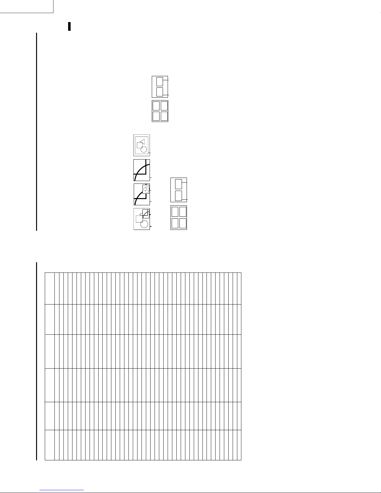
Picture in Picture (PinP)
One of the special features of this unit is the picture-
in-picture (PinP) mode. PinP allows you to view differ-
• Pressing the PinP button repeatedly will select
ent sources at the same time.
Using the PinP mode
1. Press the PinP button on the remote control.
(FRAME POSI. 5)
34
on and off.
To switch Main image and Sub image
2. Press the $ or % buttons on the remote control.
To change frame position
3. Press the { or } buttons on the remote control.
(EXPAND MODE 3) (EXPAND MODE 4)
12
FRAME POSI.
(FRAME POSI.
1〜4)
Native resolution
display
Zooming
image
Normal
image
Sub
image
Main
image
The sub image will be disappear.
available in PinP mode.
are displayed with thir frames skipped.
4. Press the PinP button on the remote control.
• Adjusting contrast, brightness, tint or color isn't
Sub
image
outputted.
• In PinP mode, both Main image and Sub image
• In PinP mode, the audio of the Main image is
• In PinP mode, the images may not move smoothly.
Still
The picture will be freezed temporary.
How to stop the picture temporarily (still picture).
1. Press the STILL button on the remote control.
again.
To resume picture activity.
2. Press the STILL button on the remote control
EN – 21
(EXPAND MODE 2)
or FRAME POSI.
FRAME POSI.
tem.
Advanced features for presentation
Expand
By pressing the EXPAND button on the remote con-
trol, you can magnify the detailed image of the picture.
You can also view the screen displaying the picture as
its original size (native resolution display).
Setting the Expand mode
1. Press the MENU button.
2. Press the $ or % to select the FEATURE menu.
3. Press the ENTER button.
4. Press the { or } button to select EXPAND MODE
5. Press the $ or % to set the EXPAND MODE or
EXPAND MODE
6. Press the MENU button twice to exit the menu sys-
(EXPAND MODE 1)
Zooming
image
Zooming
image
Normal
image
(FRAME POSI. 5)
12
FRAME POSI.
(FRAME POSI.
1〜4)
Main
image
34
Using the Expand mode
1. Press the EXPAND button.
• You can magnify different areas of the active pic-
ture by pressing the {, }, $, % button.
by pressing the + or - button.
trol.
• You can change the magnification of the zoomed area
The normal screen display will appear on the screen.
2. Press the EXPAND button twice on the remote con-
cus and the volume.
video input or S-video input.
• Display enlargement does not work with
• In EXPAND mode, you cannot adjust the zoom/fo-
143
54
TRACKING ............................. 800
HORIZ. POSITION .......................
are not shown on the table, change the resolution
of your computer. You may find the compatible reso-
lution and frequency.
• If the resolution and frequency of your computer
• Set the COMPUTER INPUT in SIGNAL menu to RGB,
VERT. POSITION .........................
when inputting the HDTV signal as RGB signal.
below, when 525p signal is inputted.
• Set the SIGNAL menu and USER menu as shown
R
P
B
/YP
R
C
B
+9
+3
620
COMPUTER INPUT ............... YC
CLAMP POSITION .......................
CLAMP WIDTH ............................
HORIZ.PIXELS .................
444
ON
VERT.LINES......................
VERT.SYNC.......................
(H x V) frequency (kHz) frequency (Hz) (H x V) (H x V)
Signal mode resolution horizontal Vertical Normal mode Real mode
TV60 – 15.73 59.94 1024 x 768 –
TV50 – 15.63 50.00 1024 x 768 –
1080i – 33.75 60.00 1024 x 576 –
720p – 45.00 60.00 1024 x 576 –
PC98 640 x 400 24.82 56.42 1024 x 640 640 x 400
CGA70 640 x 400 31.47 70.09 1024 x 640 640 x 400
CGA85 640 x 400 37.86 85.08 1024 x 640 640 x 400
VGA60 640 x 480 31.47 59.94 1024 x 768 640 x 480
VGA72 640 x 480 37.86 72.81 1024 x 768 640 x 480
VGA75 640 x 480 37.50 75.00 1024 x 768 640 x 480
VGA85 640 x 480 43.27 85.01 1024 x 768 640 x 480
SVGA56 800 x 600 35.16 56.25 1024 x 768 800 x 600
SVGA60 800 x 600 37.88 60.32 1024 x 768 800 x 600
SVGA72 800 x 600 48.08 72.19 1024 x 768 800 x 600
SVGA75 800 x 600 46.88 75.00 1024 x 768 800 x 600
SVGA85 800 x 600 53.67 85.06 1024 x 768 800 x 600
Specification of RGB signals in each computer mode of the projector
Picture adjustment (continued)
XGA43i 1024 x 768 35.52 86.96 1024 x 768 1024 x 768
XGA60 1024 x 768 48.36 60.00 1024 x 768 1024 x 768
XGA70 1024 x 768 56.48 70.07 1024 x 768 1024 x 768
XGA75 1024 x 768 60.02 75.03 1024 x 768 1024 x 768
XGA85 1024 x 768 68.68 85.00 1024 x 768 1024 x 768
SXGA70a 1152 x 864 63.85 70.01 1024 x 768 1024 x 768
SXGA75a 1152 x 864 67.50 75.00 1024 x 768 1024 x 768
SXGA85a 1152 x 864 77.49 85.06 1024 x 768 1024 x 768
SXGA60a 1280 x 960 60.00 60.00 1024 x 768 1024 x 768
SXGA75a 1280 x 960 75.00 75.00 1024 x 768 1024 x 768
SXGA43i 1280 x 1024 46.43 86.87 1024 x 768 1024 x 768
SXGA60 1280 x 1024 63.98 60.02 1024 x 768 1024 x 768
SXGA75 1280 x 1024 79.98 75.03 1024 x 768 1024 x 768
SXGA85 1280 x 1024 91.15 85.02 1024 x 768 1024 x 768
MAC13 640 x 480 35.00 66.67 1024 x 768 640 x 480
MAC16 832 x 624 49.72 74.55 1024 x 768 832 x 624
MAC19 1024 x 768 60.24 75.02 1024 x 768 1024 x 768
MAC21 1152 x 870 68.59 74.96 1024 x 768 1024 x 768
HP75 1024 x 768 62.94 74.92 1024 x 768 1024 x 768
HP72 1280 x 1024 78.13 72.00 1024 x 768 1024 x 768
SUN66a 1152 x 900 61.85 66.00 1024 x 768 1024 x 768
SUN76a 1152 x 900 71.81 76.63 1024 x 768 1024 x 768
SUN66 1280 x 1024 71.68 66.68 1024 x 768 1024 x 768
SUN76 1280 x 1024 81.13 76.11 1024 x 768 1024 x 768
SGI72 1280 x 1024 76.92 72.30 1024 x 768 1024 x 768
SGI76 1280 x 1024 82.00 76.00 1024 x 768 1024 x 768
IBM60 1280 x 1024 63.42 60.00 1024 x 768 1024 x 768
• When the EXPAND MODE of FEATURE menu is
set to real screen display, by pressing the EXPAND
button on the remote control, it will switch to the
screen displaying the picture as its original size (real
screen display). In the real screen display, pictures
will be black-framed when picture resolution is lower
than 1,024 x 768.
projector.
Important:
• Some computers may not be compatible with the
pixels. It may not display correctly for the pictures
of higher resolutions than 1,024 x 768.
jitter.
be tinged with green.
• The projector's maximum resolution is 1,024 x 768
• The picture with a SYNC on G (Green) signal may
EN – 20
• The picture with a SYNC on G (Green) signal may
Page 15
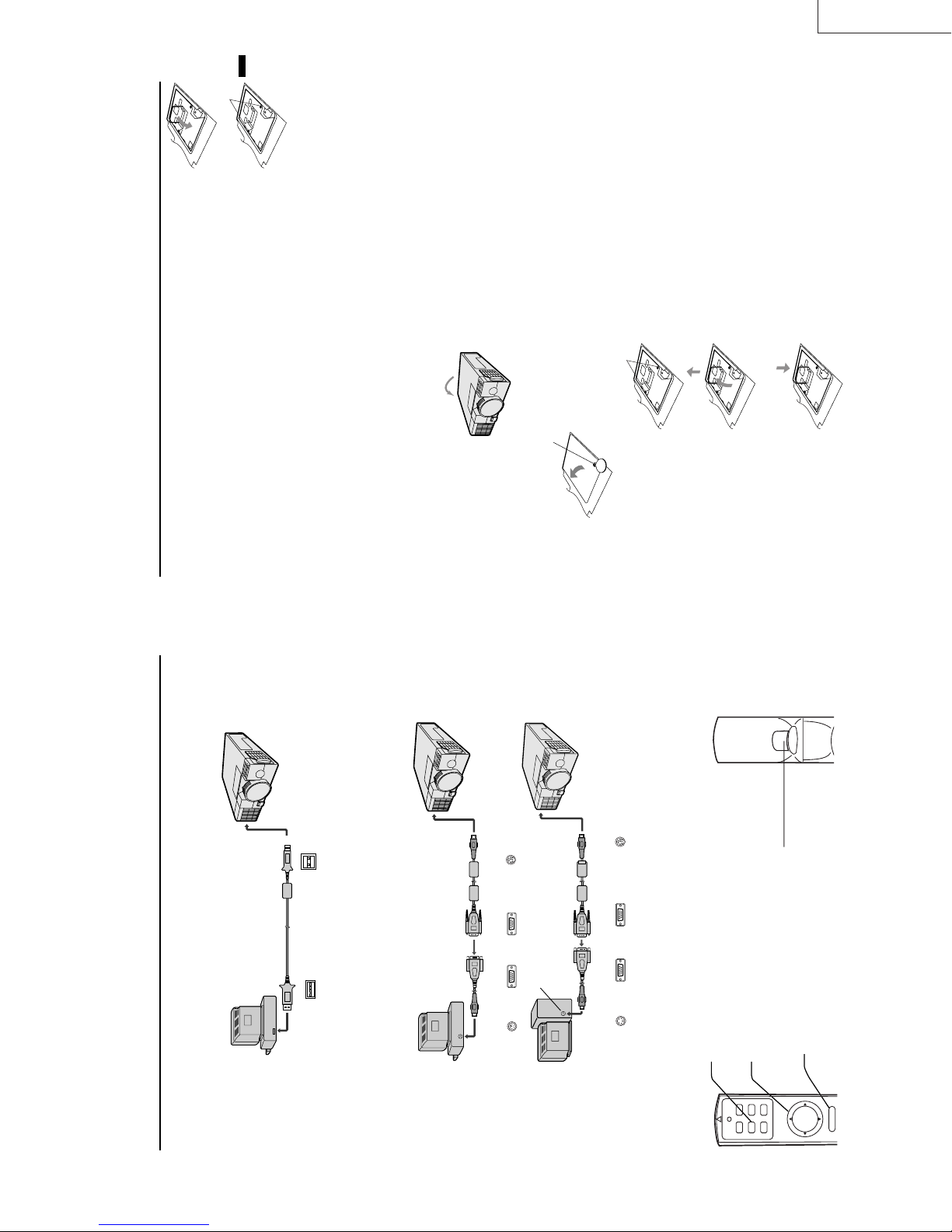
Left click
This operates in the same way as
the left button on the computer.
(a)
handle is locked.
holding point.
• Make sure that the
using a phillips screwdriver
(+).
lamp lid using a phillips
7. Put the handle back to the
8. Tighten up the screws (a)
screwdriver (+).
9. Tighten up the screws of the
ENGLISH
mable objects or where children can touch it. Oth-
erwise, it could cause injury or fire.
How to reset the operation time meter
Plug in the power cord, switch on the projector, and
reset lamp time by pressing the $, % and POWER
buttons simultaneously.
Caution:
between the right and left lamp guides.
• Do not spill liquid on the lamp or place it near flam-
• Be sure that the projector guide is firmly inserted
Important:
• The projector will not turn on if you do not secure
the lamp lid.
you replace the lamp.
lamp has been replaced.
• You must reset the operation time meter after
• Do not reset the operation time meter unless the
Interval of the lamp replacement
The interval of the lamp replacement about 2,000 hours
of consecutive use. Replacement span may differ ac-
cording to operating environment, and may be shorter
than 2,000 hours. Decreases in luminescence and/or
color brightness will indicate that the light source lamp
needs to be replaced. When lamp operation time ex-
ceeds 1,500 hours, the indicator will flash alternately
between green and red (while the lamp is in operation;
(a)
Screw of the lamp lid
LX-D1010G
EN – 23
yourself with glass fragments.
environment. For replacement lamps, please con-
when the lamp is not in operation, the indicator will
appear red only). When the lamp has been used for
about 1,900 hours, the message “LAMP!!.” will appear
on the screen for one minute. When the lamp has been
used for about 2,000 hours, the projector will automati-
cally shut off for the safety of the lamp and the power
indicator light will be red. The projector cannot be used
until the lamp has been replaced and operation timer
has been reset.
Caution:
tact your dealer.
• The lamp is fragile. If broken, be careful not to cut
• The replacement span of the lamp depends on the
The projector automatically shuts off af-
ter about 2,000 hours, and you cannot use
the projector until you replace the lamp.
off the lamp of the projector, you may get burned
because of the high temperature of the lamp.
power off, then wait for 60 seconds in stand-by mode
to allow the lamp and LCD panels to cool. Then turn
off the main switch, unplug the power cord from
the outlet, and wait one hour so that the lamp is
cooled to the touch.
The lamp is designed to project the image on the LCD
panels. When the lamp no longer functions, replace it
with a new one.
Caution:
• Do not remove the lamp immediately after turning
Lamp replacement
• For lamp replacement, press the power button to
to USB
Careless treatment can cause injury or fire.
• Do not remove the lamp except for replacement.
• Do not touch the lamp element directly. It may break
95 or lower,
®
USB 4P
(type B)
USB cable
USB 4P
(type A)
and cause you to injure or burn yourself.
jector. Also be sure not to insert metal or any flam-
mable objects, it may cause fire or electric shock. If
any objects are inserted, please unplug and contact
your dealer.
• Be sure not to drop the lamp lid screw into the pro-
1. Reverse the projector gently .
• Install the lamp securely, failure may cause a fire.
to RS-232C
terminal
using a phillips screwdriver (+) , and remove the lid.
2. Loosen the screws of the lamp lid on the top cover
Mini DIN 8P
to RS-232C
terminal
D-SUB 9PD-SUB 9PMini DIN 6P
to ADB port
PS/2 adaptor
the direction of the arrow as
indicated.
• Remove the lamp cover in
Mini DIN 8P
RS-232C cable
MAC adaptor
for MOUSE (option)
phillips screwdriver (+).
3. Loosen screws (a) using a
D-SUB 9P
D-SUB 9PMini DIN 4P
handle as you pull out the
lamp.
Once the lamp has been re-
moved, do not spill liquid on
it, place it near flammable
objects or where children can
4. Pull up the handle.
5. Hold onto the projector by the
touch it. Otherwise, it will
cause injury or fire.
into the projector body in the
right direction.
6. Insert the new lamp securely
to USB port
Advanced features for presentation (continued)
Mouse remote control
By connecting to personal computer through the USB, PS/2 or ADB port, you can operate your computer with the
projector remote control.
Connection
Projector + PC through USB connector
to mouse
(PS/2) port
98 or higher, your computer supported USB in standard. If your system is Windows
®
please contact your dealer. If your computer is Macintosh with USB port, you can use this function.
case, restart the projector and the computer. If possible, you should disconnect the USB cable when the lamp
is turned ON.
dows
• When the lamp is turned ON, the computer connected with the USB cable may not work correctly. In this
• You can use the mouse remote control function with computer supported USB only. If your system is Win-
Projector + IBM PC or IBM PC compatibles
Projector + Macintosh
Right click
This operates in the same way as the
Mouse
When pressing this button, it
illuminates. Mouse pointer/ direction
button operates as mouse pointer.
Mouse pointer
Use to move the cursor on the image,
instead of the computer mouse.
VIDEO
MOUSE LASER
POWER HIDE
projector when the personal computer is on, the remote control does not work as a mouse. In that case, restart
the personal computer.
nal which the projector recognizes first will work.
• Turn off PC and the projector before connecting with PS/2 port or ADB port. When connecting the PC with the
• When the projector is connected with USB terminal and RS-232C terminal at the same time, only the termi-
COMPUTER
Operation
right button on the computer mouse.
R-CLICK
normal mode automatically.
• When L/R click buttons and the mouse button are not used for 6 seconds, the mode will be changed to the
EN – 22
Page 16
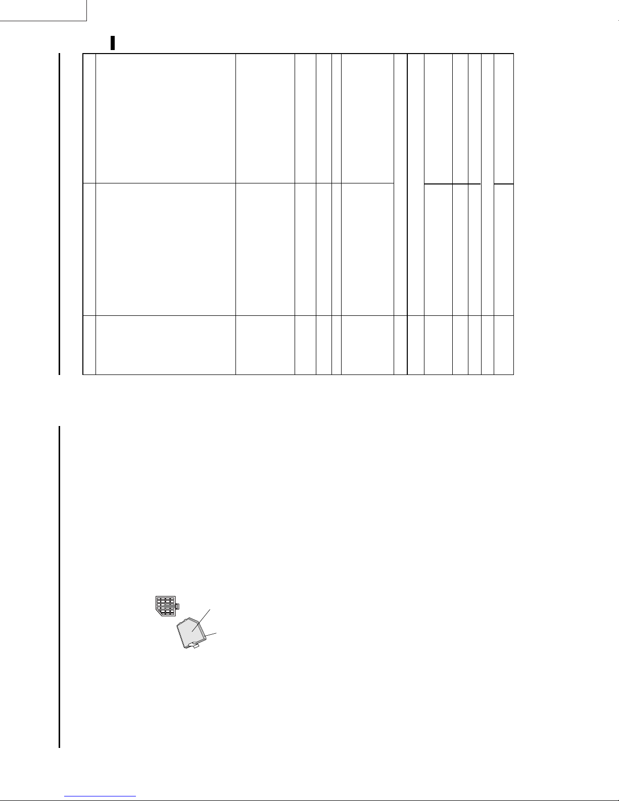
LX-D1010G
ENGLISH
EN – 25
POSSIBLE SOLUTIONS
Remove the object.
Plug the power cord into the outlet.
•
•
Wait for the lighting sequence.
Turn the main switch on.
• Insert the power cord into the projector.
•
• Close the lamp lid.
•
Refer to "Indicators" on page 26.
Replace the lamp with a new one.
• Turn the power switch on and off several times.
Close the cover correctly.•Contact your dealer.•Take the lens cap off.
•
•
•
Replace the lamp with a new one.
Turn on the connected equipment.
•
•
Select the correct source according to the equip-
ment connected to this projector.•Remove the object and turn off the main power
switch. After about 10 minutes, Turn the pro-
jector on.•Adjust the angle of the projector to make a right
angle to the screen. See page 12.
• Confirm the hookup.
•
Adjust brightness, tint and color correctly.•Adjust the projecting distance. See page 9.
•
CAUSE
clogged with dust or some objects.
• The air inlet grill, outlet grill or air filter is
POWER indicator does not light up.
• Power cord is unplugged from the outlet.
• Power cord is disconnected from the projector.
PROBLEMS
this chart before contacting your dealer.
The power is off.
The following offers solutions to some of the common problems you may encounter. We suggest that you consult
Troubleshooting
after having been turned off.
• The main switch is turned off.
• The lamp lid is open.
POWER indicator blinks red.
• The projector has been turned on again too soon
• When the power switch was turned off while
condition?)
the fan was running, during or after lamp
operation.
(Does the LAMP indicator show an unusual
Lamp is no longer working.
• The room temperature is too high.
indicator is either on or blinking, the main unit
•
• The filter cover is not closed.
• When the LAMP indicator or the TEMP
POWER indicator blinks between red and green.
requires repairs.
Lens is covered by lens cap.
indicator is either on or blinking, the main unit
requires repairs.
The equipment connected to this projector is not
turned on.•Hookup is not made correctly with other equipment.
•
• When the LAMP indicator or the TEMP
•
No picture appears
on the screen.
clogged with dust or some objects.
The input source is not selected correctly.
(In this case, the TEMP indicator does not light up.)
•
The projector is not at a right angle to the screen.
• The air inlet grill, outlet grill or air filter is
•
The image is
The image is
turned off.
Brightness, tint and color are not adjusted correctly.
The projecting distance is beyond the focused area.
•
•
The image is dark.
The image is
distorted.
Clean lens.
Reduce screen size to within 40" to 300".
Adjust brightness, contrast.
Make FINE adjustment.
Adjust the angle of the projector to make a
•
Lens is dirty.
Screen size exceeds screen size specifications.
•
•
blurred.
right angle to the screen. See page 12.
•
•
•
• Adjust tracking.
•
Brightness and contrast are not adjusted correctly.•FINE adjustment is not made correctly.
The projector is not at a right angle to the screen.
When you see the stationary image for a long time, it may remain on the screen if you change the
•
image. It is not a breakdown. The blurred image will disappear in a few minutes.
• Tracking is not adjusted.
•
•
The image remains
blurred.
terminal. See pages 10-11.
Turn up the volume.
Install the projector far away from other equipment.
Plug the connecting cable securely into the
•
•
•
It is normal.•The cable for connection with other equipment
•
Red, blue or green dots are
The image is dis-
viewed on the text of image.
• Check connections. See pages 10-11.
is not plugged securely into the terminal.
The projector is installed too close to other
equipment.
Volume is not turned up.
Connection to other equipment is not made correctly .
•
•
•
No sound is heard.
torted on the screen
and noise is heard.
Turn on the monitor.
Press the reset button on the Terminal board.
See page 15.
•
•
The PC monitor is not turned on.
This is typical of the LCD projector.•The operation is incorrectly made due to noise or
•
Nothing is displayed on
interference.
•
Warm air comes out of
Adjustments cannot be
made.
the exhaust vents.
the PC monitor.
Use a standard lens-cleaning brush or a piece of lens
tissue dampened with lens cleaning fluid. The lens sur-
face is fragile. Use only recommended, nonabrasive
lens-cleaning materials. Do not touch the lens with your
Cleaning the lens
Maintenance
Caution:
Be sure to turn off the projector and unplug the power
fingers.
gently, push the cover in the direction of the
arrow and lift.
cord from the wall outlet before you perform any main-
tenance on the projector.
Cleaning the air-filter
Clean the air-filter frequently. If the filter or ventilation
grill become clogged with dirt or dust, the temperature
inside the projector may rise and shut off the power (the
TEMP indicator starts to blink red).
For side air inlet grill
1. To remove the filter cover, press the ridged area
the filter cover.
2. Remove the air-filter from
Filter
Filter cover
detergent diluted with
water to clean the filter. Rinse the filter
thoroughly and let it dry completely.
• Use water or a mild
3. Wash the air-filter.
4. Attach the filter to the cover.
5. Reinstall the filter cover.
Important:
• If the filter is damaged or becomes extremely
dirty, contact your dealer for replacement.
improperly installed.
• The power will not turn on if the air-filter cover is
Caution:
Be sure to use the projector with an air-filter. If not,
dust may get inside the projector, causing a fire or a
breakdown.
Cleaning the projector and the ventilation
grill
Use a soft cloth to clean the projector and the ventila-
tion grill. When the grill become dirty, wipe them with
a soft cloth dampened with a diluted mild detergent,
and then wipe them with a dry cloth.
To protect the surface of the projector from fading or
deteriorating:
• Do not spray insecticide on or inside the projector.
contact with the projector.
• Do not use benzine or thinner to clean it.
• Do not let rubber or plastic materials come into
EN – 24
Page 17
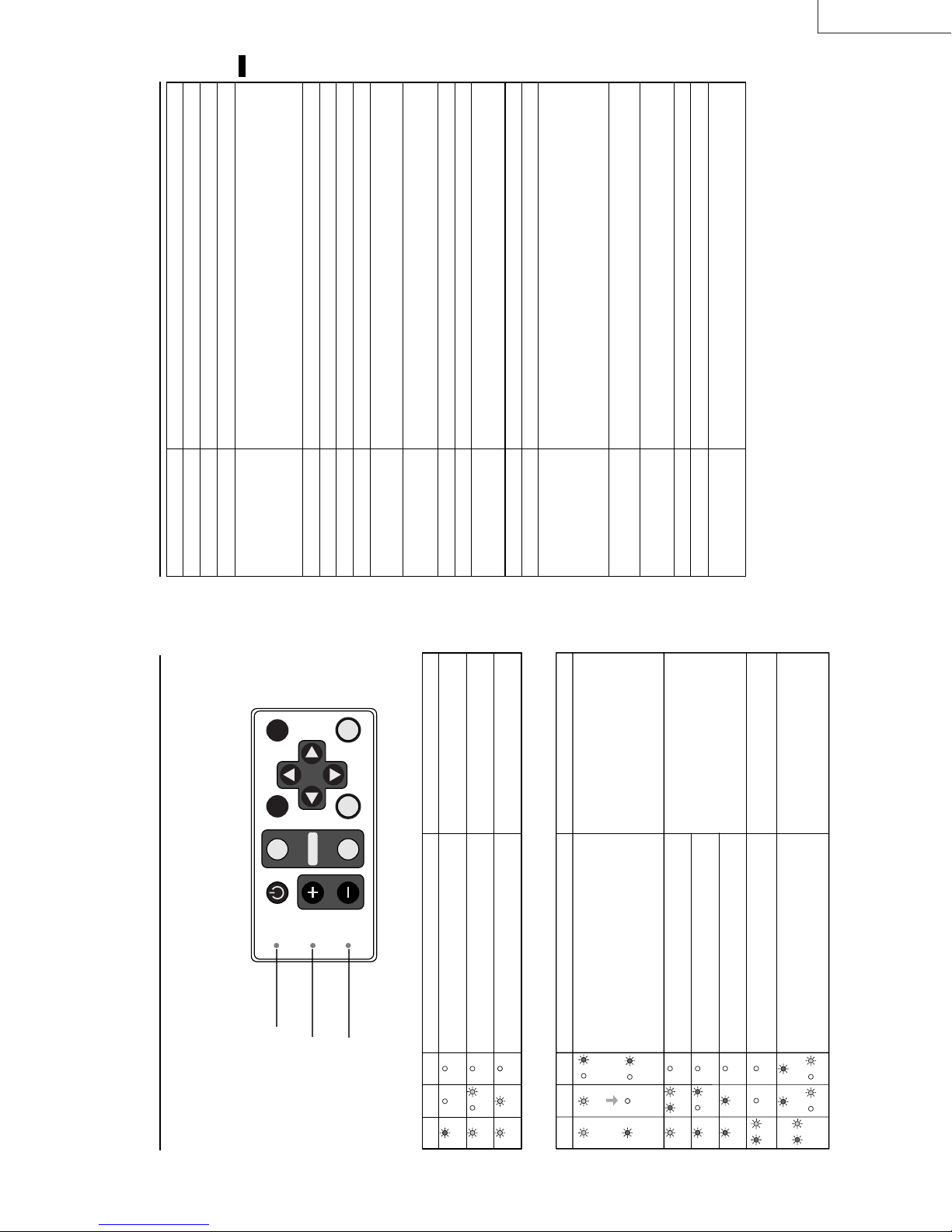
LCD projector
LX-D1010G
AC100V ~ 240V, 50 / 60Hz
ENGLISH
2.3 A
0.9-inch LCD panel: 3 pieces (for R, G, B)
Pixels 1,024 × 768 = 786,432 pixels
Total 2,359,296 pixels
Active pixel rate: 99.99 % or more (each panel)
16,770,000 colors
F 1.7~2.0 f = 33.2 mm ~ 43.1 mm
150 W UHP
40 inch ~ 300 inch (aspect ratio 4:3)
: Vp-p=0.7V
R
C
B
: Y: Vp-p=1.0V (negative sync.) C
R
C
Resolution : 640 x 400 - 1024 x 768 + Compressed 1280 x 1024
Sync on Green available
NTSC / NTSC 4.43 / PAL (including PAL-M, N) / SECAM, PAL-60
DVD (Component) / HDTV (1080i) / 720p / (525p)
1 W mono
6 cm square type (8Ω 1W)
Luminance signal: Vp-p=1.0V 75Ω (negative sync.)
Chroma signal: Vp-p=0.286V 75Ω (burst signal)
Vp-p=1.0V 75Ω (negative sync.)
B
350 mVrms, 10kΩ or more
RGB: Vp-p=0.7V 75Ω (negative sync.)
YC
HD/CS : TTL level (positive or negative)
VD : TTL level (positive or negative)
Serial (DIN 8 pin female connector) RS-232C standards
PS/2 (Mouse function), USB terminal for Mouse
Legs and lens are not included.
Approx. 3.2 kg (7 lbs)
2.9m (9.5 feet)
242 mm × 79 mm × 294 mm (9.5 inch × 3.1 inch × 11.6 inch)
(width × height × depth)
+41°F (+5°C) ~ +95°F (+35°C), 30~90%
LX-D1010G
EN – 27
Type
Model
Rated power supply
Rated input
Specifications
LCD panels
AUTO POSITION
HIDE
POWER
Colors
Projection lens
SOURCE
COMPUTER
LAMP
Light source lamp
Picture size
PC compatibility
ENTER
MENU
VIDEO
VOLUME
TEMP
Video compatibility
Audio output
Speaker
S-video input
ON and OFF
Video input
Audio inputs
Analog RGB input
(mini D-SUB 15P)
Control connector
Outside dimensions
Weight
Length of power cord
Temperature, humidity
slits.
Pull out the power plug andremove the
object. If you cannot, consult your dealer.
• Remove the object from the ventilation
•
• Relocate the projector to a cooler place.
• Clean the filter.
Replace the lamp.
Exchange with a new lamp if the same
problem recurs.
(performance guarantee)
Kensington Lock
This projector has a Kensington Security Standard connector for use with a Kensington MicroSaver Security
System. Refer to the information that came with the Kensington System for instructions on how to use it to
secure the projector. Please contact to Kensington Technology Group as shown below.
Kensington Technology Group
2855 Campus Drive
San Mateo, CA 94403, U.S.A.
Phone : (650)572-2700 Fax : (650)572-9675
LAMP indicator
POWER indicator
Indicators
The projector has three LED Indicators which shows the working condition of the projector.
The following offers solutions to possible problems. If a problem persists, turn the projector off and consult your
dealer.
TEMP indicator
Normal condition
CONDITION Notes
POWER LAMP TEMP
Stand-by
OffOff
Steady
The POWER is ON. (Normal condition)
Lamp stand-by (about for 1 minute) The power button cannot be used to switch
Off
Off
→
←
green
green
Steady
Blinking
red
green
green
Steady
Steady
dust or debris.
CONDITION POSSIBLE SOLUTIONS
Unusual temperature
• The ventilation slits or air filter is clogged with
• The fan has stopped due to an impediment.
• The room temperature is too high.
• The filter is dirty.
→
←
red
→
←
green
green
red
Blinking
Off
red
Steady
Blinking
Steady
Steady
POWER LAMP TEMP
Abnormal condition
Lamp duration warning. (Lightning duration total
about 1, 500 hours.When the POWER is ON.)
Lamp duration warning. (Lightning duration total
about 1, 500 hours.When the POWER is OFF.)
Lamp duration warning. (Lightning duration total
about 2,000 hours.)
The lamp or filter cover is not closed. Close the cover correctly.
Abnormal. Contact your dealer.
→
green/red
Steady
or or
Steady
→
←
←
→
←
Blinking
green/red
Blinking
Blinking
Off
Off
→
←
→
←
red
Blinking
Blinking
green/red
red
green
Steady
Steady
Off
Steady
Steady
Off
red
Off
→
←
red
Blinking
EN – 26
Page 18
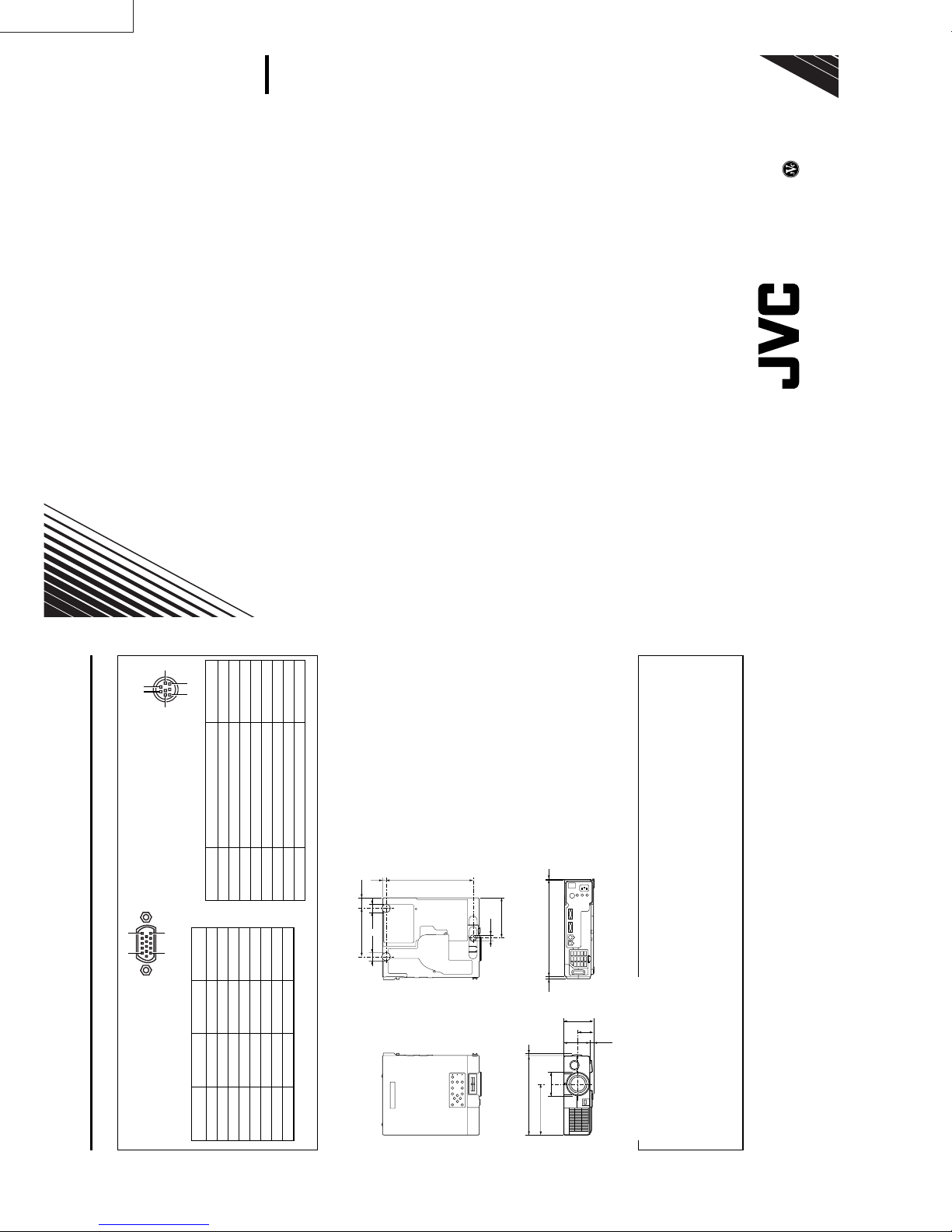
LX-D1010G
5
LX-D1010G
871D294B10
0100YMPS/VP
Printed in Japan
VICTOR COMPANY OF JAPAN, LIMITED
12
RS-232C input
11 15
PC analog RGB input
Use to input video signals (analog
Connectors
Specifications (continued)
6 8
3
Use the provided RS-232C cable (Mini
1 TXD IN
2 RTS IN
DIN 8P-D-SUB 9P) for the connection.
Use to control the projector with the
personal computer, or control the
personal computer with remote con-
trol.
PIN NO. NAME I/O
15
9−
10 GROUND
11 GROUND
B
R
G(GREEN)/Y
B(BLUE)/C
1 R(RED)/C
2
3
4 GROUND 12 DDC-DATA
PINNO. SPEC PINNO. SPEC
RGB) of a personal computer.
(Pin assignment of Mini D-SUB 15P jack)
3 DTR IN
4 GND –
5 CTS/5V IN / OUT
5 GROUND 13 HD/CS
6 GROUND 14 VD
6 DCD/CLOCK OUT
7 RXD OUT
8 RI/DATA OUT
7 GROUND 15 DDC-CLK
8 GROUND
265 11
φ26
147.5 31.5
φ26
Dimensional drawings
(mm)
φ18
122.3
1 Remote control
1 User manual
1 Quick reference card
2 Battery for remote
1 Carrying case
-SA
Ø
294 26.5
89.5
47.5
79
(10.5)
φ72.5
242 7
155
2 AC power cord
1 AV(Audio/Video) cable
1 S-Video cable
1 RGB cable for PC
1 RS-232C cable
1 PS/2 adapter
1 USB cable
What’s included in the box
7O3
ØØ
Spare Mercury lamp M-499D
Replacement part
(Option / Not included in the box)
EN – 28
Page 19

LX-D1010G
PRODUCT SERVICE PROVISIONS
1. FIELD SERVICE
(1) Servicing shall consist of the replacement of major PWBs. In general, there shall be no recycling of used boards.
The following table shows the repair method for each part.
Parts Name Repair method Parts Name Repair method
Power sub PWB Ass’y Change Board Lamp power PWB Ass’y Change Board
Video PWB Ass’y Change Board Audio PWB Ass’y Change Board
Inlet Switch PWB Ass’y Change Board Preamp PWB Ass’y Change Board
Main PWB Ass’y Change Board Lens Unit Change Unit
Power PWB Ass’y Change Board LCD Block Change Unit
① Order service parts from WPC (World Parts Center) as usual.
② Scrap defective units or PWBs yourself.
③
Request support from us in the case of difficult repair sets which you will not be able to complete yourself, even by
replacing units or PWBs. Upon receipt, we will request the OEM to make the repairs. The cost of repair, however, will be
charged to your account.
④ Spare sets will not available for repairs in Japan. Prepare these sets on your own account.
(2) Difficult repair sets
① Fill in all of the following items in REPAIR ORDER FORM OF LX-D1010G and send by fax to Projection System Dept. Also
attach a copy to the projector.
・
From ( your office )
・
Manager, Originator, Date
・
S/N
・
Detailed report of the symptoms
・
Connected input signal
・
Installation conditions, environment
・
Error display status with the self-diagnosis function operating
・
Total usage time of the light source lamp
・
Detailed report of any repair attempts
・
Previous malfunction history and repair history
② Attach only the lens cap to the projector and carefully store all other accessories until the repairs have been completed.
(3) To prevent damage, always use the original packaging and packing materials when shipping a projector. Also, use double
packaging and take any other steps thought useful for preventing damage. ( Refer to the Packing Method item. )
(4) Allow approximately four working weeks for repairs. Please note that, in some cases, even more time will be required in the
case of extended holidays.
(5) The Projection System Dept. does not advance ( Refer to page 2-1, 2. Packing Method ) replacement parts.
(6) Repair charges
Cost of parts + labor charge + Sundry expenses
Prices are not constant but depend on the problem and the number of defective units, etc.
(7) The sender bears all shipping costs, export costs, insurance, etc.
Distributors
( Distributors bear the expense ) (PS Dept. bear the expense)
→ PS Dept. PS Dept. → Distributors
(PA012) 1-1
Page 20
LX-D1010G
REPAIR
TO: Service Engineering Group Tel: 046-278-1843
System engineering Dept. Projection System Dept. Fax: 046-278-1850
Victor Company of Japan, Limited
Ymata Plant 1644, Shimotsuruma,
Yamato, Kanagawa 242-8514, Japan
FROM: Manager
Projector S/N
Failure
description
ORDER
FORM
OF
LX-D1010G
Originator
Date
Sheet No.
Packing 1. You can ask for repair services using this order sheet.
attention
2. Be sure to keep the lens cap placed on any unit to be repaired.
Keep accessories in your custody until repaired units are returned to you.
3. It is preferable that you pack the units to be repaired in the original caton box, including
cushion materials. Then, put the carton box into another larger carton box for further
protection ( double-packing ).
4. Ordinarily, 4 weeks should be sufficient for the completion of repair in Japan.
This period may, however, be somewhat extended due to continued national holidays,
5. Repair charge consists of parts and labor plus other sundry expenses.
1-2 (PA012)
JVC/PSD
Page 21
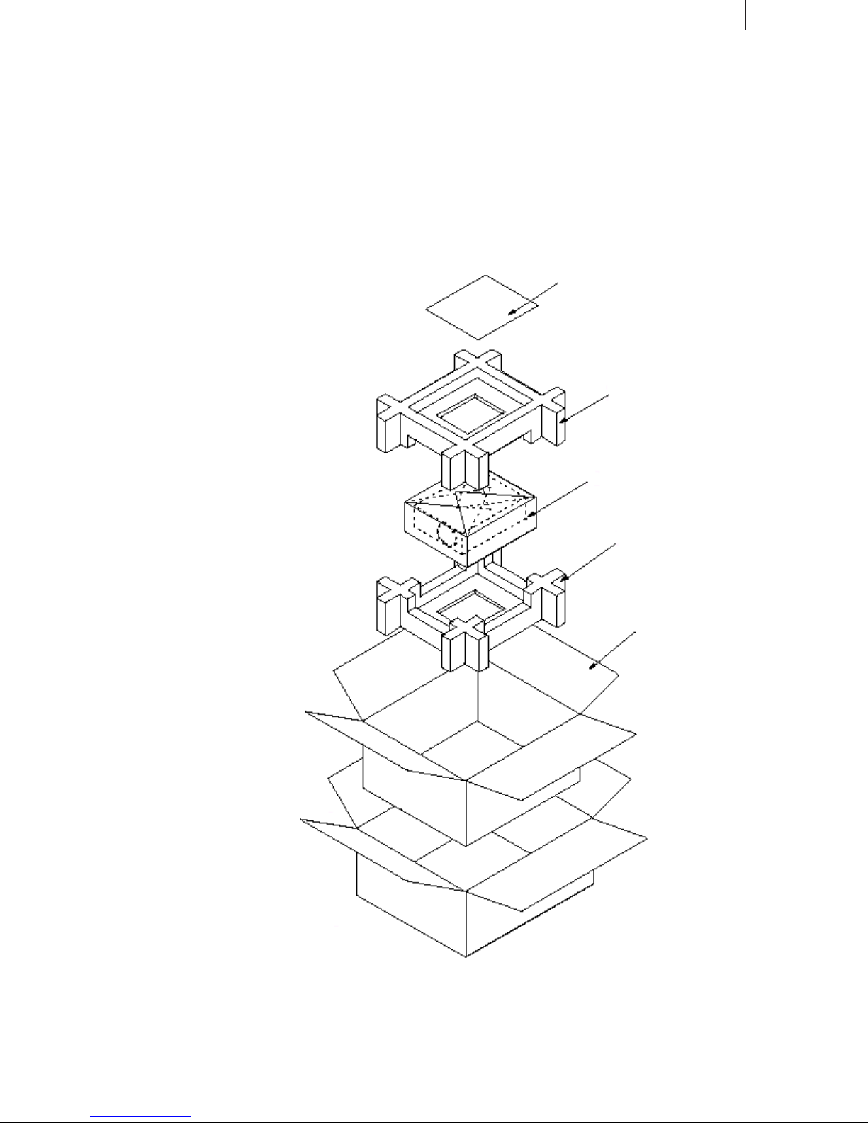
LX-D1010G
2. PACKING METHOD
When shipping, always pack projectors as described below.
Cautions
Do not send the projector accessory case or accessories when shipping a projector. Store these items carefully
****
until the repairs have been completed.
It is necessary to prepare the shipping cases, etc., required for shipping projectors.
****
Always include a repair order sheet with all necessary items filled in.
****
Fill in all of the space with cushion such as bubble cushion.
****
REPAIR OREDR FORM LX-D1010G
CUSHION TOP
M
-803A557O10
PROJECTOR
CUSHION BOTTOM
M
-803A558O10
PACKING CASE
M
-802B755O10
(PA012) 2-1
Page 22

LX-D1010G
3. BEFORE DISASSEMBLING
3.1. Cautions
Before disassembling or reassembling a projector, always read and follow the Safety Cautions found in the front of this
manual.
(1) Always turn off the power before removing or re-installing parts. Also when turning off the power, wait until the cooling fan
stops automatically and then turn off the power switch.
(2) Clamps, etc., are used to keep the internal wiring away from high-temperature parts and high-voltage parts. These should
always be returned to the original condition.
(3) When the top case has been removed, use caution to prevent the entry of foreign matter and always work in a dust-free
environment.
(4) The optical unit contains exposed optical parts such as prisms, mirrors, etc. Use caution to avoid damaging or soiling these
optical parts. Use the cleaning paper, etc., and wipe out the soil. At this time, there is a fear of damaging the coated film.
Therefore, avoid the use of solvents such as alcohol and the like.
(5) Use an air blower to remove dust from optical parts.
(6) Conductive paint is used on the insides of the top and bottom cases. If the power is turned on while a board is in contact
with this paint, there is danger of the board being damaged. Always spread the sheet located on top of the Main PWB
Ass’y before removing the Top Case Ass’y.
3.2. Tools and Equipment
・
Phillips screwdriver (20cm): for disassembly of the main unit outer case and internal parts
・
5mm nut driver: for removing nuts
・
7mm nut driver: for removing nuts
・
8mm nut driver: for removing nuts
・
Tweezers: for disconnecting FPC cables
・
Brush: for removing dust
・
Vacuum cleaner: for removing dust
・
Air blower: for removing dust
・
Cleaning paper: for cleaning glass surfaces
3-1 (PA012)
Page 23
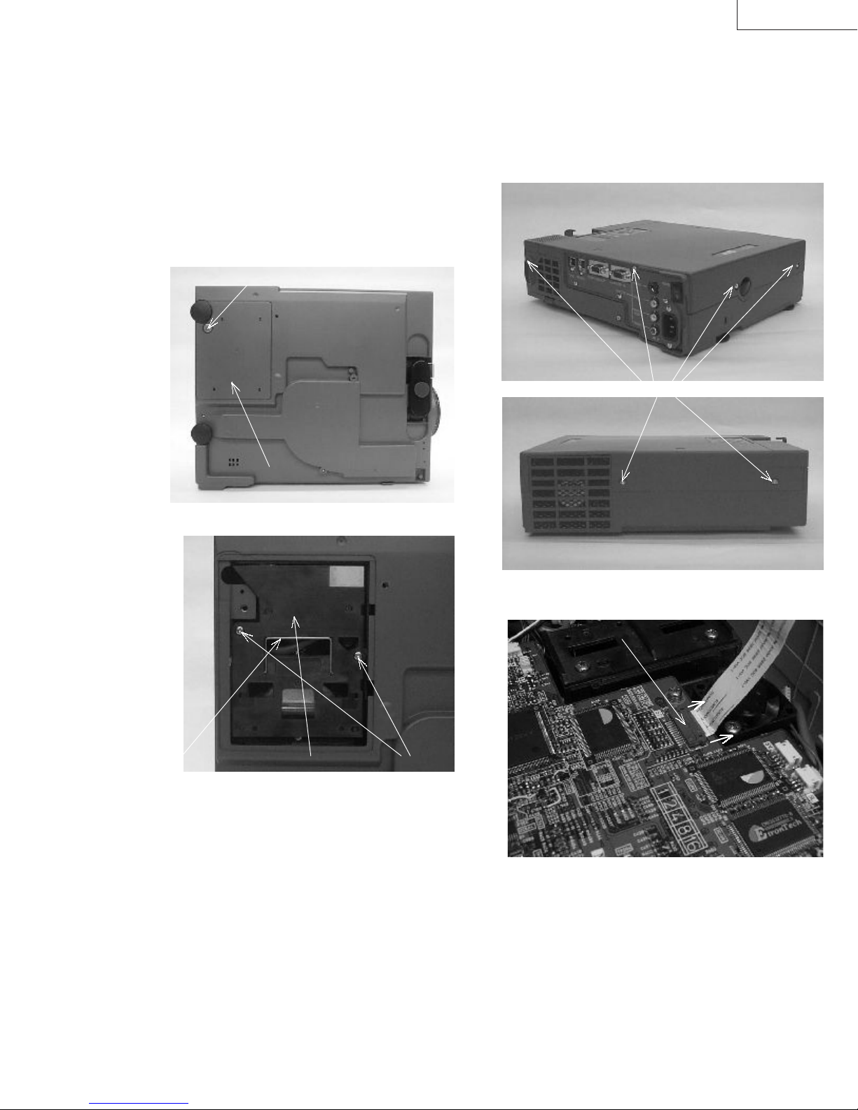
4. REMOVING MAJOR PARTS
LX-D1010G
4.1. Removing the Lamp Ass'y
Caution
Immediately after the lamp is turned off, the Lamp
****
Ass’y is extremely hot. Always allow the lamp
housing to cool for at least one hour before starting
work.
(1) Loosen the Screw A and remove the Lamp Cover.
Screw A
Lamp Cover
(2) Loosen 2 Screws B.
4.2. Removing the Top Case Ass'y
(1) Remove 6 Screws C and slowly lift straight up the Top
Case Ass’y.
Screws C
Handle Lamp Ass’y Screws B
(3) Remove the Lamp Ass’y.
(2) Release the Connector ST lock by lightly pulling in the
direction of the arrow and then disconnect the FPC wire.
Connector ST
(PA012) 4-1
Page 24
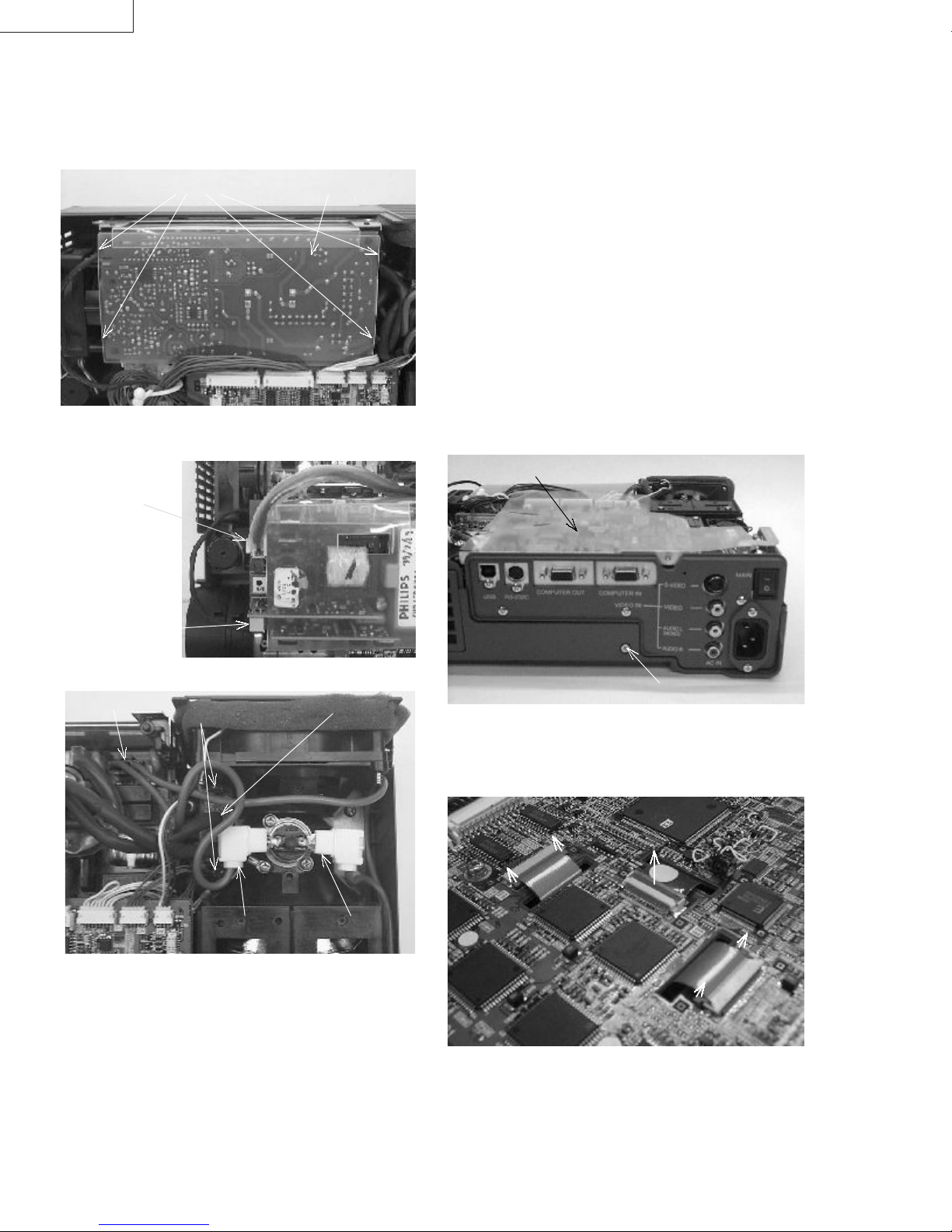
LX-D1010G
4.3. Removing the Lamp Power Unit
(1) Rem ove the Top Case Ass’y.(see 4.2)
(2) Remove 4 Hooks D and then slowly lift up the Lamp
Power Unit.
Hooks D Lamp Power Unit
(3) Disconnect the connector CB1 and CB2 of the Lamp
Power Unit.
Connector CB1
4.4. Removing the (Main PWB, Video PWB,
Inlet Switch PWB and Terminal Board)
Ass'y
Cautions
All workers should wear wristbands to prevent static
****
electricity. LCD panels are especially prone to
damage from static electricity.
Before disconnecting the FPC wires of the LCD
****
panels from the main board connector, release the
connector locks by lightly pulling upward.
When reassembling the Main PWB Ass’y, be sure to
****
return the sheet to the top of the Main PWB Ass’y. If
this sheet is forgotten, there is danger of the Main
PWB Ass’y and others being damaged when the
power is turned on.
(1) Rem ove the Top Case Ass’y.(see 4.2)
(2) Remove the Lamp Power Unit.(see 4.3)
(3) Remove the Screw I.
Sheet
Connector CB2
(4) Disconnect the connector E of the Thermal Protector.
Connector RE
Screws G
Connector E
(5) Remove 2 screws G and then disconnect the socket H of
the Lamp Power Unit.
Socket H
Connector F
Screw I
(4) Remove the Sheet.
(5) Use tweezers to release the lock by gently lifting the
connector locks of SRX, SGX and SBX connectors in the
direction of the arrow and then disconnect the FPC wires.
4-2 (PA012)
Caution
Use care not to damage the SRX, SGX and SBX
****
connectors.
Page 25
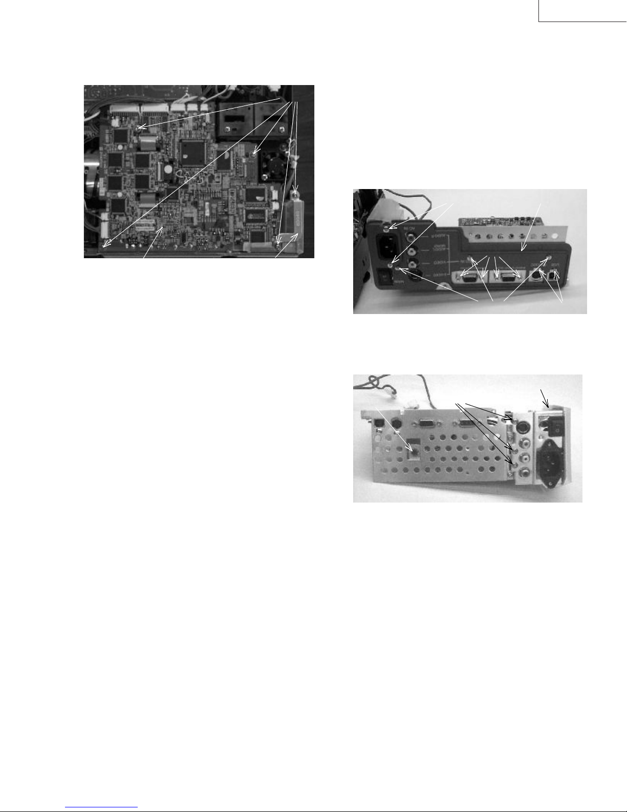
LX-D1010G
(6) Disconnect the Connector E and F of the Thermal
Protector and the Connector RE of the Power PWB Ass’y.
(7) Remove 5 Screws J and the Inlet Earth.
Screws J
Inlet EarthMain PWB Ass’y
(8) Disconnect all cables from the Main PW B Ass’y and then
slowly lift up the (Main PWB, Video PWB, Inlet Switch
PWB and Terminal Board) Ass’y.
4.5. Removing the Main PWB Ass'y, Video
PWB Ass'y, Inlet Switch PWB Ass'y
and Terminal Board
(1) Rem ove the Top Case Ass’y.(see 4.2)
(2) Remove the Lamp Power Unit.(see 4.3)
(3) Remove the (Main PWB, Video PWB, Inlet Switch PWB
and Terminal Board) Ass’y.(see 4.4)
(4) Remove 2 Screws K, 4 Screws L and connector SK
connected the Video PWB Ass’y and then remove the
Main PWB Ass’y.
Screws N Terminal Boar d
Screws L
Screws M
(5) Remove 3 Screws M and 2 Screws N and then remove
the Terminal Board.
(6) Remove 3 Screws O and then remove the Video PWB
Ass’y.
Inlet Barrier
Screws K
Screws OScrew P
(7) Remove the Screw P, the Inlet Barrier and the solder of
the metal board and then remove the Inlet Switch PWB
Ass’y.
(PA012) 4-3
Page 26

LX-D1010G
4.6. Removing the Power Ass'y
(1) Rem ove the Top Case Ass’y.(see 4.2)
(2) Remove the Lamp Power Unit.(see 4.3)
(3) Remove the (Main PWB, Video PWB, Inlet Switch PWB
and Terminal Board) Ass’y.(see 4.4)
(4) Disconnect the Connector NN of the Power Sub PWB
Ass’y.
(5) Remove 6 Screws Q and then remove the Power Ass’y.
Screws Q
4.7. Removing the Power PWB Ass'y and
the Power Sub PWB Ass'y
(1) Rem ove the Top Case Ass’y.(see 4.2)
(2) Remove the Lamp Power Unit.(see 4.3)
(3) Remove the (Main PWB, Video PWB, Inlet Switch PWB
and Terminal Board) Ass’y.(see 4.4)
(4) Remove the Power Ass’y.(see 4.6)
(5) Disconnect the Connector NP and then remove the
Power Sub PWB Ass’y.
Screws S
Connector NP Power Sub PW B Ass’y
Screws Q
(6) Remove the Screw R and then remove the Power Sub
Holder.
Power Barrier Screw R
(7) Remove the Power Holder (R), (F) and the Power Barrier.
4.8. Removing the Intake Fan (Front)
(1) Rem ove the Top Case Ass’y.(see 4.2)
(2) Remove the Lamp Power Unit.(see 4.3)
(3) Remove the (Main PWB, Video PWB, Inlet Switch PWB
and Terminal Board) Ass’y.(see 4.4)
(4) Remove the Power Ass’y.(see 4.6)
(5) Remove the Connector NP.
(6) Remove 2 Screws S and then remove the Intake Fan
(Front) from the Power Holder (F).
4-4 (PA012)
Page 27

LX-D1010G
4.9. Removing the Audio PWB Ass'y and
the Speaker
(1) Remove the Top Case Ass’y.(see 4.2)
(2) Disconnect the Connectors SY and SV of the Main PWB
Ass’y.
(3) Disconnect the Connector NN of the Power Sub PWB
Ass’y.
(4) Remove the Screw T and then remove the Audio Ass’y.
Screw T
(5) Remove several screws that fixed the Speaker and
disconnect the Connector GE of the Audio PWB Ass’y
and then remove the Speaker from the Audio Holder.
(6) Remove the screw that fixed the Audio PWB Ass’y and
then remove the Audio PWB Ass’y from the Audio Holder.
4.11. Removing the Fan (Small)
(1) Remove the Top Case Ass’y.(see 4.2)
(2) Remove 2 Screws Y and then remove the Fan (Small).
Screws Y
4.12. Removing the Intake Fan (side)
4.10. Removing the Optical Ass'y
Caution
The Optical Ass’y contains exposed optical parts
****
such as prisms, mirrors, etc. Use caution to avoid
damaging or soiling these optical parts.
(1) Remove the Top Case Ass’y.(see 4.2)
(2) Remove the Lamp Power Unit.(see 4.3)
(3) Remove the (Main PWB, Video PWB, Inlet Switch PWB
and Terminal Board) Ass’y.(see 4.4)
(4) Remove the Audio Ass’y.(see 4.9)
(5) Remove 4 Screws W and the Metal Board X and then
slowly lift up the Optical Ass’y.
Metal Board X
(1) Remove the Top Case Ass’y.(see 4.2)
(2) Remove the Lamp Power Unit.(see 4.3)
(3) Remove the (Main PWB, Video PWB, Inlet Switch PWB
and Terminal Board) Ass’y.(see 4.4)
(4) Remove the Optical Ass’y.(see 4.10)
(5) Remove 2 Screws Z and then remove the Intake Fan
(side).
Intake Fan(side)
Screws Z
Screws W
(PA012) 4-5
Page 28

LX-D1010G
4.13. Removing the LCD Block
Caution
All workers should wear wristbands to prevent static
****
electricity. LCD panels are especially prone to
damage from static electricity.
(1) Remove the Top Case Ass’y.(see 4.2)
(2) Remove the Lamp Power Unit.(see 4.3)
(3) Remove the (Main PWB, Video PWB, Inlet Switch PWB
and Terminal Board) Ass’y.(see 4.4)
(4) Remove the Optical Ass’y.(see 4.10)
(5) Remove 6 Screws AA and then remove the Cooling
Cover of the bottom.
Cooling C over
4.14. Removing the Exhaust Fan Ass'y
(1) Rem ove the Top Case Ass’y.(see 4.2)
(2) Remove the Lamp Power Unit.(see 4.3)
(3) Remove the (Main PWB, Video PWB, Inlet Switch PWB
and Terminal Board) Ass’y.(see 4.4)
(4) Remove the Optical Ass’y.(see 4.10)
(5) Remove 2 Screws AC and then remove the Exhaust Fan
Ass’y.
Exhaust Fan Ass’y
Screws AC
Screws AA
(6) Hold the LCD Block to remove 3 Screws AB and then
take out the LCD Block.
Screws AB
4-6 (PA012)
Page 29

LX-D1010G
4.15. Removing the Polarizers
Cautions
The Polarizers are made by adhering polarizing film
****
to a glass plate. Use caution to avoid damaging the
film and glass plate.
There are three Polarizers: for R, G and B.
****
These Polarizers are not interchangeable.
The Polarizer for R is marked in red; the one for G is
marked in green; and the one for B is marked in blue.
When installing the Polarizers, always check the
color of the markings.
The Polarizers are directional. Position the Polarizer
****
with the film side facing the LCD panel and with the
marking upward.(on the side of the LCD panel FPC
wire)
Film
LCD Panel
Glass
Polarizer
Markings
For R: red
For G: green
For B: blue
(6) Remove the Polarizers.
Polarizer for G
Polarizer for B Polarizer for R
(1) Remove the Top Case Ass’y.(see 4.2)
(2) Remove the Lamp Power Unit.(see 4.3)
(3) Remove the (Main PWB, Video PWB, Inlet Switch PWB
and Terminal Board) Ass’y.(see 4.4)
(4) Remove the Optical Ass’y.(see 4.10)
(5) Remove 9 Screws AD and 6 Screws AE and then slowly
lift up the Optical Cover.
Optical Cover
Screws AD Screws AE
(PA012) 4-7
Page 30
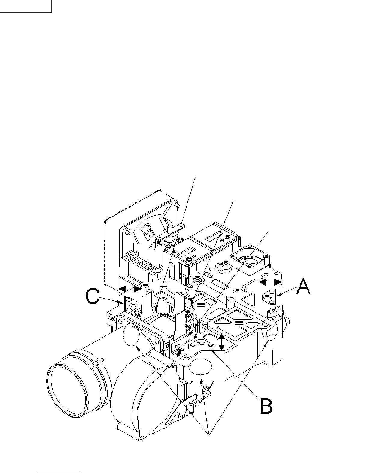
LX-D1010G
4.16. Adjustments after the Removing the
Polarizers or PBS Ass'y
Cautions
Adjust each Mirror locations when the PBS Ass’y or
****
the Polarizers have been replaced or the Optical
Cover has been removed and put back.
Use the Lamp-on Tool (M-859C670O20) instead of the
****
Main PWB Ass’y when perform the adjustments.
(1) Do not move the lower part of each Mirror.
If you move the lower part, the adjustments will be very
difficult.
(2) Adjust to balance the light on the screen and the G LCD
Panel surfaces evenly by moving the part A in the
direction of the arrow. Fix the part A at the best position.
(3) Adjust to balance the light on the screen and the R LCD
Panel surfaces evenly by moving the part A in the
direction of the arrow. Fix the part A at the best position.
(4) Adjust to balance the light on the screen and the B LCD
Panel surfaces evenly by moving the part A in the
direction of the arrow. Fix the part A at the best position.
B LCD Panel
G LCD Panel
R LCD Panel
4-8 (PA012)
Do not move the lower part of each Mirror.
Page 31

◎
About the Lamp-on Tool
Use the Lamp-on Tool when adjust or check the Optical Ass’y
without the Main PWB Ass’y.
This tool will be needed mainly when remove the dust on the
LCD Block.
Operation
LX-D1010G
(1) Perform (1), (3)-(5) and (7) of 4.4. Removing the (Main
PWB, Video PWB, Inlet Switch PWB and Terminal Board)
Ass'y.
(2) Disconnect all cables from the Main PWB Ass’y.
(3) Perform (4) of 4.5. Removing the Main PWB Ass'y, Video
PWB Ass'y, Inlet Switch PWB Ass'y and Terminal Board.
(4) Connect all cables to the Lamp-on Tool.
(5) Connect the AC Power Cord and then turn on the Power
Switch.
(6) Turn on the switches in the order of POWER-ON,
FAN-ON and LAMP-ON.
(7) The lamp turn on and then adjust or check.
SF
SD
(8) After finishing the work, turn off the switch of LAMP-ON.
(9) Wait for 2 minutes after lamp off and then turn off the
switches in the order of FAN-ON and POWER-ON.
(10) Turn off the Power Switch and then disconnect the AC
Power Cord.
(11) Remove the Lamp-on Tool and then put back the Main
PWB Ass’y and the Top Case Ass’y.
SA
LAMP-ON
SY
SW
SX
POWER-ON
FAN-ON
(PA012) 4-9
Page 32

LX-D1010G
Memo
4-10 (PA012)
Page 33

LX-D1010G
5. HYPER TERMINAL SETTING METHOD
This projector uses a communication program of the
Microsoft
projector, adjust the circuits and to correct the time that the
light source lamp is used.
*” Windows
either Windows
(1) Equipment requirements
・
(2) Startup
①
②
③
④
®
Windows®95 Operating System to control the
®
95” indication means that can be operated on
®
95 or Windows®98.
®
A personal computer with the Microsoft
Operating System installed.
Start Windows®95.
Double click on the Accessories folder.
Double click on the Hyper Terminal folder.
Double click on the Hypertrm icon to open the Hyper
Terminal window.
Double click on the Hypertrm icon.
Windows®95
⑥
When the Phone Number dialogue box opens, set the
connection using the port where the RS-232C cable is
connected and then click on the OK button.
Set the port to be used.
⑦
Set the port in the COM* Properties dialogue box, then
click on the OK button.
⑤
When the New Connection dialogue box opens, input
an appropriate name and select an icon, then click the
OK button.
Item Setting
Bits per second 9600
Data bits 8
Parity None
Stop bits 1
Flow control None
(PA012) 5-1
Page 34

LX-D1010G
⑧ Click on Properties in the File menu to open the
Properties dialogue box, then click on Settings and set
Emulation to VT-100.
Setting emulation
(3) Exiting
Click on the Close button in the upper right corner of the
Hyper Terminal window to close Hyper Terminal.
Click on the Close button
⑨ Click on ASCII set up to set ASCII, then click on the OK
button.
Item Setting
ASCII Sending Send line ends with line feeds
Echo typed characters locally
Line delay: 1000ms
Character delay: 10ms
ASCII Receiving Append line feeds to incoming line ends
5-2 (PA012)
Page 35

LX-D1010G
6. PERSONAL COMPUTER
CONNECTION METHOD
This projector uses a personal computer to control the projector and adjust the circuits.
(1) Equipment requirements
・
Projector
・
A personal computer with a COM port and the Microsoft
Personal computers without a COM port cannot be used.
・
The RS-232C cable provided with the projector.
(2) Connection Method
①
Before using the RS-232C cable to connect, make sure the power of the projector and personal computer are turned off.
②
Use the RS-232C cable provided with the projector to connect the projector RS-232C terminal and the COM port of the
personal computer.
Projector RS- 232C t er minal
®
Windows®95 Operating System installed.
③
Startup
Turn on the power of the projector and the personal computer in that order.
④
Exiting
Turn off the power of the personal computer and the projector in that order.
Personal computer COM port
(PA012) 6-1
Page 36

LX-D1010G
Memo
6-2 (PA012)
Page 37

LX-D1010G
7. CIRCUIT ADJUSTMENT METHOD
The communication program Hyper Terminal of the Microsoft® Windows®95 operating system is used to make all circuit
adjustments for this projector. Refer to 5. Hyper Terminal Setting Method (page 5-1).
(1) Equipment required for adjustm ents
・
Projector
・
Personal computer (refer to 6. Personal Computer Connection Method page 6-1)
・
The RS-232C cable provided with the projector
・
XGA signal generator or personal computer with the Microsoft
external XGA display (resolution 1024x 786, H: 48.36kHz, V: 60.00Hz).
・
LX-D1000&D1010 Adjustment Video Source software (necessary when a personal computer is used to input test signals
into the projector, not necessary when using an XGA signal generator).
This software can be downloaded from JS-Net*1 on the Internet.
(2) Connection Method
XGA signal generator
or personal computer
RGB-IN RS-232C
Projector
®
Windows®95 operating system installed and capable of
*1: http://gisa.yh.jvc-victor.co.jp/
Personal
computer
(3) Test signals
・
XGA signal (H: 48.36 [kHz] V: 60.00 [Hz])
The timing and pattern are shown below
H timing
Pattern
HDW
HBP HDISP
HP
V timing
Pattern
VDW
VBP VDISP
VP
RS-232C cable
XGA signal (vertical frequency 60Hz) timing
DOT-CLOCK [MHz] 65.0
HP [DOT] 1344
HDISP [DOT] 1024
HDW [DOT] 136
HBP [DOT] 160
VP [H] 806
VDISP [H] 768
VDW [H] 6
VBP [H] 29
Interlaced no
Sync polarity
No. Pattern
01 XGA signal all white 100%
05 XGA signal all white 50%
06 XGA signal all white 20%
12 XGA signal SMTPE(red)
13 XGA signal SMTPE(green)
14 XGA signal SMTPE(blue)
22 XGA signal alternate line horizontal stripe (red 50%)
23 XGA signal alternate line horizontal stripe (green 50%)
24 XGA signal alternate line horizontal stripe (blue 50%)
HD: negative,VD: negative
(PA012) 7-1
Page 38

LX-D1010G
(4) Adjustment
① Connect a XGA signal generator or personal computer to the RGB-IN jack of the projector.
When using a personal computer as an XGA signal generator, provide another set of personal computer to input
adjustm ent commands (adjustment values). In short, we need two sets of personal computers in total.
②
Use the RS-232C cable provided with the projector to connect the RS-232C terminal of the projector and the COM port of
the personal computer. (Refer to (2) Connection Method page 7-1)
③ Turn on the power switch of the projector.
④ Turn on the power of the personal computer and open the Hyper Terminal window. (Refer to 5. Hyper Terminal Setting
Method page 5-1)
⑤ Press the power button on the Operation Unit or the remote controller to turn on the light source lamp and project a test
signal.
⑥ Make the following adjustments as necessary.
1 A/D converter input amplitude Perform when the Main PWB Ass’y has been replaced.
2 Ghost Perform when the Ghosts are prominent in the video after either the Main PWB Ass’y or
the LCD Block has been replaced.
3 Flicker Perform when the Flicker is prominent in the video after either the Main PWB Ass’y or the
LCD Block has been replaced.
4 Gray color balance Perform when the Color Balance is lost of gray signal after either the Main PWB Ass’y or
the LCD Block has been replaced.
(5) Writing adjustment values
Commands and adjustment values are input into the Hyper Terminal window in upper case alphanumerics from the keyboard
of the personal computer.
Always press the ENTER key after input at such times.
Caution:
* Circuit adjustment items 1. A/D converter input amplitude are performed automatically, so the writing of adjustment
values of adjustment commands as well as write command and adjustment value write operations are
unnecessary.
(6) Exiting
Click on the button in the upper right corner of the Hyper Terminal window to exit Hyper Terminal.
7-2 (PA012)
Page 39

LX-D1010G
The bottom 3 digits of the return command indicate whether adjustment was successful or failed.
[A/D Preamp Circuit]
1. A/D converter input amplitude
Input signal
Input terminal Analog RGB
[LCD panel drive adjustment circuit]
2. Ghost
Input signal Refer to the chart below
Input terminal Analog RGB
No. Pattern
12 XGA SMTPE(R)
13 XGA SMTPE(G)
14 XGA SMTPE(B)
No. 01
XGA all white 100%
Purpose of adjustment: To set the amplitude of the video signal being into the A/D converter.
Symptom when adjustment is incomplete: Colors are added to monochrome video.
Purpose of adjustment: To minimize ghosts on the images
Symptom when adjustment is incomplete: Ghosts with a width of 12 pixels appear in the images.
* Input adjustment commands in upper case alphanumerics.
1. Input the XGA signal (all white 100%, No.01).
2. Input [00~5](A/D adjustment command) in the Hyper Terminal window to start automatic
adjustment.
3. When adjustment is completed, the return command [00~5111] will be returned in the Hyper
Terminal window.
The sequence is R, G and B from the left.
1 means success.
0 means failure resulting from PWB malfunction, signal error, input selection error, etc.
*1 Perform this adjustment only when the Ghosts are prominent in the video after either the
Main PWB Assy or the LCD Block has been replaced.
*2 Input the adjustment commands and values in upper case characters.
1. Use the following as the default values in the IMAGE MENU.
CONTRAST ------------- 0
BRIGHTNESS ---------- 0
COLOR TEMP. --------- STANDARD
COLOR MATRIX ------- OFF
Red
2. Input the XGA signal (SMTPE (R), No. 12).
3. Input the adjustment command [00~30C] in the Hyper Terminal window to minimize
ghosts in the red image.
In the , input the value from among the 5 types of [008], [009], [00A], [00B] and [00C] so that
the ghost can be reduced to a minimize value, resulting in the entirely well balanced screen
(center and periphery of four corners). (*3)
4. Input the write command [00~1829] in the Hyper Terminal window to write the changed
value to the EEPROM.
In the , enter the value of 2 figures of the lower part in the in Item 3. (*3)
Green
5. Input the XGA signal (SMTPE (G), No. 13).
6. Input the adjustment command [00~30D] in the Hyper Terminal window to minimize
ghosts in the green image.
In the , input the value from among the 5 types of [008], [009], [00A ], [00B] and [00C] so that
the ghost can be reduced to a minimize value, resulting in the entirely well balanced screen
(center and periphery of four corners). (*3)
7. Input the write command [00~182B] in the Hyper Terminal window to write the changed
value to the EEPROM.
In the , enter the value of 2 figures of the lower part in the in Item 6. (*3)
Blue
8. Input the XGA signal (SMTPE (B), No. 14).
9. Input the adjustment command [00~30E] in the Hyper Terminal window to minimize
ghosts in the blue image.
In the , input the value from among the 5 types of [008], [009], [00A ], [00B] and [00C] so that
the ghost can be reduced to a minimize value, resulting in the entirely well balanced screen
(center and periphery of four corners). (*3)
10. Input the write command [00~182D] in the Hyper Terminal window to write the changed
value to the EEPROM.
In the , enter the value of 2 figures of the lower part in the in Item 9. (*3)
*3 If the command was correctly sent, it will be returned as sent. Also, the current value can
be checked by sending with only [00~30C], [00~1829], [00~30D], [00~182B], [00~30E] or
[00~182D] (with nothing entered in or ).
(PA012) 7-3
Page 40

LX-D1010G
A
[LCD panel drive adjustment circuit]
3. Flicker
Inp ut si gnal Refer t o t he char t below
Input terminal Analog RGB
No. Pattern
22 Red 50% alternate line
horizontal pattern
23 Green 50% alternate line
horizontal pattern
24 Blue 50% alternate line
horizontal pattern
lternate line horizontal patt ern
Purpose of adjustment: To minimize flicker on the images
Symptom when adjustment is incomplete: Flic ker appears in the images.
*1 Perform this adjustment only when the flicker is prominent in the video after either the Main
PWB Ass’y or the LCD Block has been replaced.
*2 Perform this adjustment after heat running f or 2 minutes over with input test signal.
*3 Input the adjustment commands and values in upper case char acters.
1. Use the following as the default values in the IMAGE ME NU.
CONTRAST ------------- 0
BRIGHTNESS ---------- 0
COLOR TEMP. --------- STANDARD
COLOR MATRIX ------- OFF
2. Project an image on the screen.
Red
3. Input the XGA signal (Red 50% alternate line horizontal pattern, No.22).
4. Input the adjustment command [
flicker in the red image.
Input the hexadecimal digit from [00] to [FF] in the
is written in the
(*4)
5. Input the write command [
value to the EEPROM.
Enter the value input in the
Green
6. Input the XGA signal (Green 50% alternate line horizontal pattern, N o. 23).
7. Input the adjustment command [
flicker in the green image.
Input the hexadecimal digit from [00] to [FF] in the
is written in the
(*4)
8. Input the write command [
value to the EEPROM.
Enter the value input in the
of the Main PW B Ass’y (before adjustment) in the service parts stock.
□□
of the Main PW B Ass’y (before adjustment) in the service parts stock.
□□
00~221
00~1810
in item 4. (*4)
□□
00~222
00~1811
in item 7. (*4)
□□
□□
□□
] in the Hyper Terminal window to minimize
□□
to minimize the flicker. The value [A0]
□□
] in the Hyper Terminal window to write the changed
] in the Hyper Terminal window to minimize
□□
to minimize the flicker. The value [A0]
□□
] in the Hyper Terminal window to write the changed
Blue
9. Input the XGA signal (Blue 50% alternate line horizontal pattern, No. 24).
10. Input the adjustment command [
flicker in the blue image.
Input the hexadecimal digit from [00] to [FF] in the
is written in the
(*4)
11. Input the write c ommand [
value to the EEPROM.
Enter the value input in the
*4 If the command was c orrectly sent, it will be returned as sent. Also, the current value can
be checked by sending with only [
[
] (with nothing entered in
00~1812
of the Main PW B Ass’y (before adjustment) in the service parts stock.
□□
00~223
00~1812
□□
in item 10. (*4)
□□
□□
] in the Hyper Terminal window to minimize
□□
to minimize the flicker. The value [A0]
□□
] in the Hyper Terminal window to write the changed
00~221
.
)
], [
00~222
], [
00~223
], [
00~1810
], [
00~1811
] or
7-4 (PA012)
Page 41
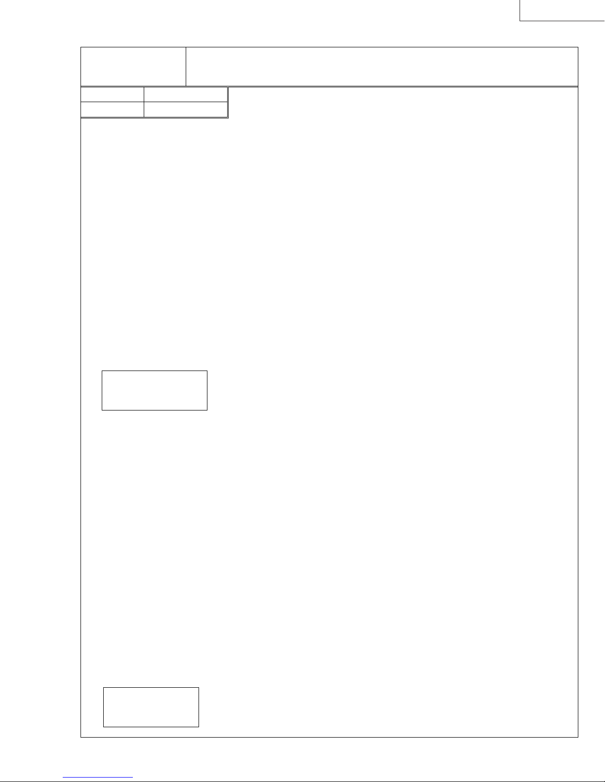
LX-D1010G
[Gamma correction circuit]
Purpose of adjustment: T o optimize the white balanc e of the images
4.1 W hite balance (50%)
Symptom when adjustment is incomplete: Colors are added to monochr ome image.
Input signal No. 05 All white 50%
Input terminal Analog RGB
*1 Perf orm this adjustment only when th e C olor Balance is lost of gray signal (50%) after eith er the
Main PW B Ass’y or the LCD Block h as been replaced.
*2 Perform this adjustment after heat running for 2 minutes over with input test signal.
*3 Input the adjustment c ommands and values in upper case characters.
1. Input the XGA signal (All white 50%, No. 05).
2. Use the following as the default values in the IMAGE MENU.
CONTRAST ------------- 0
BRIGHTNESS ---------- 0
COLOR TEMP. --------- STANDARD
COLOR MATRIX ------- OFF
3. Project an image on th e screen and then perform the heat running for 2 minutes over .
4. Perform the item 5 in case of without the color tone/differential meter.
Perform the it ems 6-9 in case of using the c olor tone/differential meter.
In case of without the color tone/differential meter
5. Adjust using each R , G and B adjustment command to be without color at the center of the
picture.
The adjustment commands are R: [
00~801
Input the numeral of the decimal notation R: [
It will be returned as s ent. (*4)
.
□□□
□□□
], G: [
-30
] - [
00~802
], G: [
+10
□□□
-20
] and B: [
] - [
+05
00~803
] or B: [
□□□
-50
] - [
].
+50
] in the
If the adjustment value is incr eased, the objective color will be increased, als o.
If the adjustment value is decr eased, the objective color will be decreased, als o.
Input the write command [
] in the Hyper Terminal window to write the changed value to
00~81
the EEPROM. (It will be returned as sent.)
Adjustment specification:
x = 0.277
+0.010
-0.015
y = 0.329±0.010
In case of using the color tone/differential meter
6. Measure the color differential value at the center of the picture.
If the x and y value are within the adjustment specification, exit this adjustment.
7. Adjust the
G Gamma Bright 50%
to be within the adjustment specific ation only for the y value.
If the adjustment value is increased, the y value will be increased, also.
If the adjustment value is decreased, the y value will be decreased, also.
Input the adjustment command [
In the
, input the numeral of the decimal notation from [
□□□
00~802
adjustment specification for the y value. It will be returned as sent.
Input the write command [
] in the Hyper Terminal window to write the changed value to
00~81
] in the Hyper Terminal window.
□□□
-20
(*4)
] to [
] to be within the
+05
the EEPROM. (It will be returned as sent.)
If the y value c ould not be within the adjustment specification by the G Gamma Bright 50%
adjustment, adjust the
B Gamma Bright 50%
to be within the adjustm ent specification only f or
the y value.
If the adjustment value is decreased, the y value will be increased, also.
If the adjustment value is increased, the y value will be decreased, also.
Input the adjustment command [
In the
, input the numeral of the decimal notation from [
□□□
00~803
adjustment specification for the y value. It will be returned as sent.
Input the write command [
] in the Hyper Terminal window to write the changed value to
00~81
] in the Hyper Terminal window.
□□□
-50
(*4)
] to [
] to be within the
+50
the EEPROM. (It will be returned as sent.)
8. Adjust the
R Gamma Bright 50%
to be within the adjustm ent specification only for the x value.
If the adjustment value is increased, the x value will be increased, also.
If the adjustment value is decreased, the x value will be decreased, also.
Input the adjustment command [
In the
, input the numeral of the decimal notation from [
□□□
00~801
adjustment specification for the x value. It will be returned as sent.
Input the write command [
] in the Hyper Terminal window to write the changed value to
00~81
] in the Hyper Terminal window.
□□□
-30
(*4)
] to [
] to be within the
+10
the EEPROM. (It will be returned as sent.)
*4 The current value can be checked by sending with only [
nothing entered in
□□□
.
)
00~801
], [
00~802
] or [
00~803
] (with
Allowance limit:
x = 0.277
y = 0.329
+0.010
-0.015
+0.010
-0.045
9. Repeat the item 6-8 to be within the adjustment specific ation for both value x and y.
If they will never be within the adjustment specification, it will be permit within the allowance
limit.
(PA012) 7-5
Page 42

LX-D1010G
[Gamma correction circuit]
Purpose of adjustment: To optimize the white balance of the images
4.2 White balance (20%)
Symptom when adjustment is incomplete: Colors are added to monochrome imag e.
Input signal No. 06 All white 20%
Input terminal Analog RGB
*1 Perf orm this adjustment only when th e C olor Balance is lost of gray signal (20%) after eith er the
Main PW B Ass’y or the LCD Block h as been replaced.
*2 Perform this adjustment after heat running for 2 minut es over with input test signal.
*3 Input the adjustment commands and values in upper case characters.
1. Input the XGA signal (All white 20%, No. 06).
2. Use the following as the default values in the IMAGE MENU.
CONTRAST ------------- 0
BRIGHTNESS ---------- 0
COLOR TEMP. --------- STANDARD
COLOR MATRIX ------- OFF
3. Project an image on the screen and then perform the heat running f or 2 minutes over.
4. Perform the item 5 in case of without the color tone/differential meter.
Perform the it ems 6-9 in c ase of using the c olor t one/differential meter.
In case of without the color tone/differential meter
5. Adjust using each R , G and B adjustment command to be without color at the center of the
picture.
The adjustment commands are R: [
00~821
Input the numeral of the decimal notation R: [
It will be returned as s ent. (*4)
.
□□□
□□□
], G: [
-30
] - [
00~822
], G: [
+10
□□□
-20
] and B: [
] - [
+05
00~823
] or B: [
-50
□□□
] - [
].
+50
] in the
If the adjustment value is increased, the objective color will be increased, also.
If the adjustment value is decreased, t he objective color will be decreased, als o.
Input the write command [
] in the Hyper Terminal window to write the changed value to
00~83
the EEPROM. (It will be returned as sent.)
Adjustment specification::
x = 0.277
+0.010
-0.015
y = 0.329±0.010
In case of using the c olor tone/differential meter
6. Measure the color differential value at the center of the picture.
If the x and y value are within the adjustment specification, exit this adjustment.
7. Adjust the
G Gamma Bright 20%
to be within the adjustment specification only for the y value.
If the adjustment value is increased, the y value will be incr eased, also.
If the adjustment value is decreased, the y value will be decreased, also.
Input the adjustment command [
In the
, input the numeral of the decimal notation from [
□□□
00~822
adjustment specification for the y value. It will be returned as sent.
Input the write command [
] in the Hyper Terminal window to write the changed value to
00~83
] in the Hyper Terminal window.
□□□
-20
(*4)
] to [
] to be within the
+05
the EEPROM. (It will be returned as sent.)
If the y value could not be within the adjust ment specific ation by the G Gamma Bright 20%
adjustment, adjust the
B Gamma Bright 20%
to be within the adjustment specific ation only for
the y value.
If the adjustment value is decreased, the y value will be increased, also.
If the adjustment value is increased, the y value will be decr eased, also.
Input the adjustment command [
In the
, input the numeral of the decimal notation from [
□□□
00~823
adjustment specification for the y value. It will be returned as sent.
Input the write command [
] in the Hyper Terminal window to write the changed value to
00~83
] in the Hyper Terminal window.
□□□
-50
(*4)
] to [
] to be within the
+50
the EEPROM. (It will be returned as sent.)
8. Adjust the
R Gamma Bright 20%
to be within the adjustment specification only for the x value.
If the adjustment value is increased, the x value will be incr eased, also.
If the adjustment value is decreased, the x value will be decreased, also.
Input the adjustment command [
In the
, input the numeral of the decimal notation from [
□□□
00~821
adjustment specification for the x value. It will be returned as sent.
Input the write command [
] in the Hyper Terminal window to write the changed value to
00~83
] in the Hyper Terminal window.
□□□
-30
(*4)
] to [
] to be within the
+10
the EEPROM. (It will be returned as sent.)
*4 The current value can be checked by sending with only [
nothing entered in
□□□
.
)
00~821
], [
00~822
] or [
00~823
] (with
Allowance limit:
x = 0.277
y = 0.329
+0.010
-0.015
+0.010
-0.045
9. Repeat the item 6-8 to be within the adjustment specification for both value x and y.
If they will never be within the adjustment specification, it will be permit within the allowance
limit.
7-6 (PA012)
Page 43

8. ABOUT HIDDEN COMMANDS
LX-D1010G
The buttons of the Operation Unit can be
operated to acquire data concerning the
projector and, when a personal computer
is connected, to also change some of the
data.
The data shown here is recorded in the
Main PWB Ass’y.
Use caution with this function because
some of the data is not included in the
instruction manual.
8.1 Service Menu
1) Display method
①
Turn on the main power switch.
②
Press [POWER] button to turn on the lamp.
③
Press [▲], [▼] and [ENTER] button of the Operation Unit at the same time to display the SERVICE MENU 1.
Press [MENU] button when the SERVICE MENU 1 is being displayed to display the SERVICE MENU 2.
Press [MENU] button when the SERVICE MENU 2 is being displayed to exit.
2) Display contents
SERVICE MENU1
S/W VER : 1.33
SET TIME :2100H 30M
LAMP TIME : 200H 30M
LAMP RESET : 1
TABLE NO : 5
ASFV : 8341
ASFL : 525
*1 The data can not be reset.
SERVICE MENU2
L-ON COUNT : 99
L-NG COUNT : 2
TEMP-ERR TIME:0H 0M
IN-TEMP :30.0 ゚ C( 0.0)
LCD-TEMP :36.5 ゚ C( 0.0)
LAMP-TEMP :60.5 ゚ C( 0.0)
FAN MODE :3 ( 0 )
ERR MODE :00000
*2. The number in the ( ) indicate the temperature when the power turned off caused by unusual temperature.
*3. The number in the ( ) indicate the fan speed mode when the power turned off caused by unusual temperatur e.
*4. If the power-off by unusual temperature has been nothing, “0” is displayed.
*5. The 5 digits numbers show the condition in order of ①, ②, ③, ④, ⑤ from left. The digit that corresponded to the condition
of the power-off indicates “1”, the others indicate “0”. The condition numbers and contents are as follows.
Condition numbers Cause of power-off
①
②
③
④
⑤
The IN-TEMP was over 43.5
The LAMP-TEMP was over 150
The LCD-TEMP was over 63.5
[POWER] button
POWER
LAMP
TEMP
[-] button
Software version number
Total set usage time (Total lamp usage time)(*1)
Lamp usage time (The data is reset when the user perform the LAMP RESET)
Number of times the LAMP TIME was reset
The selected signal number in the auto select table
ASFV value (Vertical frequency information of the input signal)
ASFL value
Number of times the lamp was turned on (This count the turn on action whether
succeeded or failed
Number of times the lamp-on was failed (excluding the lamp went out)
The SET TIME when the power turned off caused by unusual temperature (If the
above power-off has been nothing, “
Temperature of the intake air (*2, *4)
Temperature at the top of the LCD panel (*2, *4)
Temperature of the lamp (*2, *4)
Fan speed mode(*3, *4)
Condition for the power turned off caused by unusual temperature (*4, *5)
Always “0”
Always “0”
(Total line number in 2V term)
VOLUME
℃
℃
℃
[ ] button
CONPUTER
SOURCE
VIDEO
[MENU] button
AUTO POSITION
0H 0M
” is displayed)
MENU
[▼] button
[▲] button
HIDE
ENTER
[ ] button
[ENTER] button
(PA012) 8-1
Page 44

LX-D1010G
y
y
8.2 Function Menu
1) Display method
①
Turn on the main power switch.
②
Press [POWER] button to turn on the lamp.
③
Select the LANGUAGE of the OPTION Menu.
④
Press the key of the Remote Controller in order of [STILL], [+], [ENTER] to display the
FUNCTION MENU.
2) Functions
TEST SIGNAL OFF, 1-4 1: White 100%
2: Black
3: Cross Hatch
4: Color Bar
±
A/D LEVEL
5
Maxim um Range:
±
10%
LINE DUBLER ON/OFF Line Doubler on/off For demonstration
±
Y/C DELAY
3
72nsec * default
(for comp/s input)
BLUE BACK ON/OFF Blue Back on/off
REAL TIME FINE ON/OFF Always FINE Mode This function is unstable.
35 KEY STONE -35, OFF,
Setting for 35
°
+35
Select “OFF” to display the input
signal.
Use when the Contrast cannot be
adjusted too much.
Select “OFF” to perform the
keystone adjustment.
[STILL] ke
[+] ke
8.3 Tips to initialize menu contents and warning record
①
Turn on the main power switch.
②
Press [MENU], [ENTER] and [-] button of the Operation Unit simultaneously to initialize.
Caution
* The initialized menu will turn to a display in English. If you find it necessary to set a
language, re-set the language displayed by a language selection on the OPTION MENU.
8.4 How to reset the LAMP TIME
①
Turn on the main power switch.
②
Press [POWER], [
] and [ ] button of the Operation Unit simultaneously to reset.
8.5 System Reset
Perform the System Reset when the projector has hung up caused by the runaway of microcomputer.
Push the reset button in the hole of the Terminal Board by the sharp-pointed tool.
8-2 (PA012)
Page 45

LX-D1010G
9. WHEN REPLACEMENT OF THE MAIN
PWB ASS'Y IS NECESSARY
When replacem ent of the Main PWB Ass’y becomes necessary, it is necessary to write the adjustments data and the lamp time
etc. recorded in the old Main PWB Ass’y to the new Main PWB Ass’y. Refer to the command tables about various commands.
The following information is about the LAMP TIME by way of example.
1) Equipment requirements
・
Projector
・
Personal computer (refer to 6. Personal Computer Connection Method page 6-1)
・
The RS-232C cable provided with the projector.
2) Method
①
Before using the RS-232C cable to connect, make sure the power supplies of the projector and personal computer are
turned off.
②
Use the RS-232C cable provided with the projector to connect the projector RS-232C terminal and the COM port of the
personal computer.
③
Turn on the main power switch of the projector.
④
Turn on the power of the personal computer and open the Hyper Terminal window. (Refer to 5. Hyper Terminal Setting
Method page 5-1)
⑤
Input the lamp time display command [
returned in the Hyper Terminal window as the return command. Record the part below on paper, etc.
00~l
] ([l] is a lower case L) in the Hyper Terminal window. The lamp time will be
Input [
Input [
00~l000217 →
00~l500000 →
000217
was recorded,
00~l000217
500000
00~l500000
.
①①①①
]. Make sure that [
was recorded,
]. Make sure that [
2 hours 17 minutes
500 hours
00~l000217
00~l500000
] is returned in the Hyper Terminal window as return command.
] is returned in the Hyper Terminal window as return command.
⑤⑤⑤⑤ [00000~
] is input in the Hyper
0~llll
0~0~
Example:
Example:
⑥
Tern off the main power switch and replace the Main PWB Ass’y.
⑦
Perform the operations in ① - ④ and then open the Hyper Terminal window.
⑧
Input the value recorded in ⑤ in the Hyper Terminal window.
Example: When
Example: When
⑨
Check the input data using hidden commands. (Refer to 8. About Hidden Commands page 8-1)
Cautions
* If the Hyper Terminal window is not functioning correctly (return commands are not being sent), check the following
items.
Refer to 5. Hyper Terminal Setting Method page 5-1 and recomfirm the setting item.
・
Repeat from item
・
* When the Hyper Terminal window is functioning correctly and communication between the projector and personal
computer is normal, the return command will be returned from the projector when item
Terminal window.
(PA012) 9-1
Page 46

LX-D1010G
Contents Read
Ghost
Flicker
Color
Temperature
(50%)
Color
Temperature
(20%)
Ghost R
Ghost G
Ghost B
Flicker R
Flicker G
Flicker B
R 50% 1
R 50% 2
G 50% 1
G 50% 2
B 50% 1
B 50% 2
R 20% 1
R 20% 2
G 20% 1
G 20% 2
B 20% 1
B 20% 2
Adjustment Command Table
Write
Commands
00~1829 00~1829[D][D]08-0C
00~182B 00~182B[D][D]08-0C
00~182D 00~182D[D][D]08-0C
00~1810 00~1810[D][D]00-FF
00~1811 00~1811[D][D]00-FF
00~1812 00~1812[D][D]00-FF
00~1900 00~1900[D][D]00-FF
00~1906 00~1906[D][D]00-FF
00~1901 00~1901[D][D]00-FF
00~1907 00~1907[D][D]00-FF
00~1902 00~1902[D][D]00-FF
00~1908 00~1908[D][D]00-FF
00~1903 00~1903[D][D]00-FF
00~1909 00~1909[D][D]00-FF
00~1904 00~1904[D][D]00-FF
00~190A 00~190A[D][D]00-FF
00~1905 00~1905[D][D]00-FF
00~190B 00~190B[D][D]00-FF
Commands
Data
Range
Remarks
Record the value of 2 figures of the lower part in the data.
Record the value of 2 figures of the lower part in the data.
Record the value of 2 figures of the lower part in the data.
Service Command Table
Contents Read Commands Write Commands Data
SET TIME
LAMP TIME
LAMP RESET
L-ON COUNT
L-NG COUNT
S/W VER
00~s 00~sHHHHHMM
00~l 00~lHHHHMM
00~142F 00~142FNN 00-FF
00~1402 00~1402NN 00-FF
00~1403 00~1403MM 00-FF
00~1404 00~1404NN 00-FF
00~1405 00~1405MM 00-FF
00~VER 00~VER*.**_D101
Range
Remarks
00~sHHHHHMM (HHHHH
Reply:
00~lHHHHMM (HHHH
Reply:
00~142FNN
Reply:
(NN: Number of times the LAMP TIME was reset <hex>)
00~1402NN
Reply:
00~1403MM
Reply:
NNMM
(
: Number of times the lamp was turned on <hex>)
00~1404NN
Reply:
00~1405MM
Reply:
NNMM
(
: Number of times the lamp-on was failed <hex>)
00~VER*.**_D101
Reply:
: hours, MM: minutes)
: hours, MM: minutes)
( _ : space)
9-2 (PA012)
Page 47

LX-D1010G
10. USING THE WARNING ACQUISITION
SOFTWARE
It has been confirmed that this software will operate under Microsoft® Windows® 95.
1) Equipment requirements
・
Projector
・
Personal computer (refer to 6. Personal Computer Connection Method page 6-1)
・
The RS-232C cable provided with the projector.
・
Warning History Acquisition software [Pcgc7e(XGA).exe] and [pcgc7e(xga).ini] (This software ban be downloaded from
Internet JS-Net: http://www.gisa.yh.jvc-victor.co.jp/. Install [pcgc7e(xga).ini] file in the Windows folder.)
2) Program startup
①
Before using the RS-232C cable to connect, make sure the power supplies of the projector and personal computer are
turned off.
②
Use the RS-232C cable provided with the projector to connect the projector RS-232C terminal and the COM port of the
personal computer.
③
Turn on the main power switch of the projector.
④
Turn on the power of the personal computer.
⑤
Double click on the program file
opened in accordance with the specifications and then communication between the projector and personal computer will
start.
[Pcgc7e(XGA).exe] to start the pr ogram
. When this program starts, the serial port will be
0001016
(PA012) 10-1
Page 48

LX-D1010G
3) Warning status
When the program starts, warning data will be acquired automatically from the projector and the results will be displayed.
The item in which an error has occurred will be checked in the check box. If the warning data cannot be acquired correctly, the
data will not be displayed in the main dialogue box.
If the warning data cannot be acquired correctly, click the [warning status] button to re-acquiring the warning status data.
4) Warning history
When the [History1], [History2] or [History3] button is clicked, the last, two times before or three times before warning data will
be acquired from the projector respectively and the results will be displayed.
The item in which an error has occurred will be checked in the check box. If the warning data cannot be acquired correctly, the
data will not be displayed in the main dialogue box.
5) Clearing the warning history
After correcting the error, perform the clearing the warning history.
When the [ALL CLEAR] button in the main dialogue box is clicked, a command will be sent from the personal computer to the
projector to clear the all of warning history and the error display will be cleared.
6) When a communication error occurs
When a message such as “No response from the projector.” Is displayed, check the following items.
・
Is the main power switch of the projector turned on ?
・
Is the RS-232C cable correctly connected ?
・
Is the COM port to which the RS-232C cable is connected correctly set ?
・
Has the prescrived procedure been used to start the projector and personal computer ?
7) Saving the warning data
When the [DETAIL] button in the main dialogue box is clicked, the [DataTemp.txt] file will be opened by the NOTEPAD and
then save this file in case of need.
8) Exiting the program
Click the [CLOSE] button to exit the program.
10-2 (PA012)
Page 49

LX-D1010G
11. ABOUT INDICATOR ERROR DISPLAYS
This projector has a self-diagnosis function. When a projector malfunction is detected, the operation unit indicator will indicate
an error.
Indicator
AUTO POSITION
POWER
CONPUTER
LAMP
VOLUME
TEMP
SOURCE
VIDEO
MENU
1) Diagnosing
・
Turn on the main power switch to perform an automatic self-diagnosis.
・
In about a second after turning on the main power swtch, the power will start and remain on for approximately 4 seconds,
and check individual sessors. At this time, a power indicator of the operation unit will remain on in red.
・
Even if you press the power button during a sensor check, sometimes there can be a case where the lamp does not light
up.
・
If you turn on the main power switch, individual fans will run for 15 seconds or so.
HIDE
ENTER
2) Self-diagnosis results display
The indicator error displays and the types of problems indicated are shown in the following table. When a detected malfunction
can be corrected, the indicator will display “Can be recovered automatically” (written as [Auto] in the [Reset]), “Reset by
turning the main power switch off and then on again” (written as [Main Power] in the [Reset]) or “Replace the lamp and reset
the lamp time to recover” (written as [Manual] in the [Reset]).
3) Emergency power on
Emergency power on is possible when the power cannot be turned on using the normal method due to a standby power short
or switched power short and it is necessary to turn the power on to detect errors.
・
Turning the power on
The power can be turned on during a sensor check by pressing the [HIDE], [ENTER] and [VIDEO] buttons of the operation
unit at the same time for approximately 4 seconds.
When the power is turned on in this manner, the protection circuit will operate for everything other than a standby power
short or a switched power short.
4) Error display table
Indicator Display Check PointPreferential
Order
POWER LAMP TEMP
1 Off Off Off
Symptom Failure
PWB Reference
The power fan stops. AC system (Primary power source) failure Inlet
The power fan is operating.
Secondary power source failure Power
CHIECHIP is not operating Main IC700-80 (RESET)
Microcomputer is not operating Main IC7A0-115 (RESET)
CPU bus failure Main IC7A0-CA0-17, CD0-15
Operation unit failure Main
Power
PFC
Main
Operation Unit
STBY5 (SF-6)
STBY3.3 (IC7A4-8pin)
X700 (25MHz)
IC7A0-7 (12.5MHz)
IC700-CA0-17, CD0-15
ST Connector Main Power
Reset
Main Power
Main Power
Main Power
Main Power
Main Power
Off: indicator off
Orange: both red and green light
Red flash N: the cycle that red flashes N times and goes out for fixed time is repeated.
(PA012) 11-1
Page 50

LX-D1010G
Indicator Display Check PointPreferential
Order
10 Red Green flash Off No power on for one
11 Green Green Off No power off for one
12 Red Green flash Off No power on for one
POWER LAMP TEMP
2 Red/Green
alternately
Red/Green
3
alternately
Red/Green
alternately
Red/Green
alternately
Red/Green
alternately
Red/Green
alternately
Red/Green
alternately
Red/Green
alternately
Red/Green
4
alternately
Red/Green
alternately
Red/Green
alternately
Red/Green
alternately
alternately
6 Red/Green
alternately
Red/Green
alternately
Red/Green
alternately
8
9
Red Off Red
Red Off Red
Red Off Red
Red Red flash Off
Green Red/Green
Red Red Off No power on
Green Red No power on IIC bus 1 failure (EEPROM) Main IC705
Orange Red
flash
Orange Red
flash 2
Orange Red
flash 3
Orange Red
flash 4
Orange Red
flash 5
Orange Red
flash 6
Orange Red
flash 7
Red Red
flash
Red Red
flash 2
Red Red
flash 3
Red Red
flash 4
Off Off No power on
Off Red
flash
Green Red
flash 2
Green Red
flash 3
flash
flash 2
flash 3
Off
alternately
Symptom Failure
No power on STBY power Power
No power on SW5D power Power Sub
No power on SW3.3 power Power Sub
No power on SW15.5 power Power
No power on SW12 power Power
No power on SW5A power Power
No power on SW9AU power Power Sub
No power on FAN STOP: Intake fan Main SY Connector Main
No power on FAN STOP: Exhaust fan Main SW Connector Main
No power on FAN STOP: Power unit fan Power Sub NP Connector Main
No power on FAN STOP: PBS fan Main SX Connector Main
No power on Missing thermistor Main SZ Connector Auto
No power on IIC bus 2 failure (DECODER) Main IC2A2
No power on AV bus failure Main IC700-AAD0-23
No power on High intake air temperature (outside
No power on High temperature around the lamp Setting Covered vent Auto
No power on High temperature around the PBS
Warning indicated by the
LED during STBY
Warning indicated by the
LED during power on
minute
minute
minute
Reset
PWB Reference
ICLK0, IDA0
SD Connector
Main
STBYR5 (SD-8)
SD Connector
Main
SW5D ( SF-8)
SD Connector
Main
SW3.3 (SF-10)
SD Connector
Main
SW15.5 (SD-2)
SD Connector
Main
SW12 (SD-4)
SD Connector
Main
SW5A (SD-6)
Audio
Lamp cover open
(Power on prohibited for safety)
Filter cover open
(for dust in prevention)
air temperature)
(LCD)
Warning that the and of lamp’s life
span is near (1500-2000h)
Warning that the and of lamp’s life
span is near (1500-2000h)
Power on prohibited due to the end
of lamp’s life span (more than 2000h)
Lamp failure Not a malfunction Auto
For one minute after power on Not a malfunction Auto
For one minute after power off Not a malfunction Auto
Power Sub SN Connector
Power Sub SN Connector
Setting Room temperature not conforming
Setting Clogged intake at the side. Auto
Not a malfunction Manual
Not a malfunction Manual
Replace the lamp and then reset the lamp time.
(Press the [POWER], [ ] and [ ] buttons at
the same time.)
SD Connector
SW9AU (SV-2)
Main
Lamp cover
Filter cover (side)
ICLK1-45p, IDA1
IC400-AAD0-23
to the specification.
Auto
Main
Power
Main
Power
Main
Power
Main
Power
Main
Power
Main
Power
Main
Power
Power
Power
Power
Power
Auto5 Red/Green
Auto
Auto7
Auto
Auto
Manual
11-2 (PA012)
Page 51

LX-D1010G
12. ENTRY
Errors are checked in accordance with the following flow chart. Advance to the flow chart for the relevant item on the following
pages.
Start
・
External checkout
External checkout
Checks for external problems (case damage, etc).
(See page 12-2)
Internal cable
connection
Power system 1
Power system 2
Power system 3
Power system 4
Video system
・
Internal cable connection checkout
Checks the cable connector connections.
(See page 12-3)
・ No standby status
The power indicator does not light.
(See page 12-4)
・ When the self-diagnosis function shows a standby
power short
(See page 12-5)
・ When the self-diagnosis function shows a switched
power short
(See page 12-6)
・
When the lamp does not light
(See page 12-7)
・
When the video does not appear normally
(See page 12-8)
(PA012) 12-1
Page 52

LX-D1010G
A
1) External checkout
Start
Top Case Ass’y/Bottom Case Unit
Operation Unit
Lens Ass’y
Filter Cover
Perform the checks after turning off the power and
disconnecting the power cable and connecting cables.
・
Is there any damaging, deformation or cracks due to dropping, etc.?
・ Is it screwed tightly?
・ Is there any dirt or foreign matter (tape, etc.) on the photoreceptor for the
remote control?
・ Is the Operation Unit correctly installed?
・
Are there any bad contact or stuck buttons?
・ Do the focus and zoom rings operate smoothly?
・ Is the lens dirty or damaged?
・ Is the Filter Cover installed correctly to the Bottom Case Unit?
・ Has the protuberance A of the Filter Cover fram e been
damaged?
・ Is the Filter dirty?
・ Is the Blower (intake) dirty?
Lamp Cover
Lamp Ass’y
Adjuster/Adjuster (R)
Input terminal
AC Inlet
・ Is the Lamp Cover installed correctly to the Bottom
Case Unit?
・ Has the protuberance B of the Lamp Cover
frame been damaged?
B
・ Are there any traces of deformation or burning (discoloration)
in the plastic frame? Is the lamp damaged?
・ Is the Lamp connector discolored?
・ Can the Adjuster and Adjuster (R) be adjusted smoothly?
・ Are any of the connectors or jacks deformed or discolored?
・ Is the foreign matter adhered to any of the connectors or jacks?
・
Are any of the connector jacks discolored?
・
Is the socket damaged?
12-2 (PA012)
Page 53
2) Internal cable connection checkout
y
y
Top Case Ass’y, removal
Operation Unit
Speaker
Thermistor Ass’y
・
Perform the checks after turning off the power and disconnecting
the power cable and connecting cables.
・
Indicate the connectors as follows:
CN: (Name of connector)
・
Main PWB Ass’y CN: ST
・
Audio PW B Ass’y CN: GE
・
Main PWB Ass’y CN: SZ
LX-D1010G
Photoreceptor for remote control (front / rear)
Video PW B Ass’
LCD Block
Power Sub PWB Ass’
Main PWB Ass’y ⇔ Lamp Power Unit
Main PWB Ass’y ⇔ Power PWB Ass’y
Fan
Power Sub PWB Ass’y ⇔ Power PWB Ass’y
・
Main PWB Ass’y CN: SV ⇔ Audio PWB Ass’y CN: GV
・
Main PWB Ass’y CN: SL ⇔ Preamp PWB Ass’y CN: AL
・
Main PWB Ass’y CN: SK ⇔ Video PWB Ass’y CN: TK
・
Main PWB Ass’y CN: SRX/CN: SGX/CN: SBX
・
Main PWB Ass’y CN: SF ⇔ Power Sub PWB Ass’y CN: NF
・
Power PWB Ass’y CN: RB ⇔ Power Sub PWB Ass’y CN: NB
・
Audio PW B Ass’y CN: GN ⇔ Power Sub PWB Ass’y CN: NN
・
Main PWB Ass’y CN: SA ⇔ Lamp Power Unit CN: CB2
・
Main PWB Ass’y CN: SD ⇔ Power PWB Ass’y CN: RD
・
Power Sub PWB Ass’y CN: NP
・
Main PWB Ass’y CN: SW/CN: SX/CN: SY
・
Power Sub PWB Ass’y CN: NB ⇔ Power PWB Ass’y CN: RB
Power PWB Ass’y ⇔ Lamp Power Unit
Top Case Ass’y, installation
・
Power PWB Ass’y CN: RE ⇔ Lamp Power Unit CN: CB1
(PA012) 12-3
Page 54

LX-D1010G
IC951
necessary
primary SW-HIC
The Main PWB Ass'y
The Audio PWB Ass'y
3) Power system 1
Cannot enter standby status
Is there the fuse blown?
No
Is the thermostat conducting?
No
Is the lead to the RF
connector conducting?
Yes
Is there 5V or more at
pin 6 of the NF connector?
LED does not light.
Check the STBY5.
Yes
Yes
No
Disconnect the SF
No
connector from the
Main PWB Ass'y.
Check for shorts on the Power
PWB and replace the parts
(D900, Q900, etc.) if necessary.
Reset the thermostat
and check if the filter is dirty.
Replace the lead.
Is there 5V
or more at pin 6 of the
CN: NF?
Yes
The thermostat is on the Lamp Ass'y.
IC950:
IC951: secondary feedback IC
Z954, Z955: cicuit protectors
Check the circuit around the IC950,
No
and replace the parts if
(specially Z954, Z955).
Yes
If you replace the
Main PWB Ass'y, is the status
become standby?
Yes
The Main PWB Ass'y
failure
No
The Operation Unit failure
If you replace the
Main PWB Ass'y, is the status
become standby?
No
If you replace the
Audio PWB Ass'y, is the status
become standby?
No
If you replace the
Preamp PWB Ass'y, is the status
become standby?
No
The Operation Unit failure
Yes
Yes
Yes
failure
failure
The Preamp
PWB Ass'y failure
12-4 (PA012)
Page 55

4) Power system 2
Z950 or Z951
LX-D1010G
Cannot enter standby status
Is the RD-SD lead conducting?
Yes
Disconnect the SD connector
from the Main PWB Ass'y.
Is there -5V or
more at pin 8 of the RD
connector?
Yes
The Main PWB Ass'y failure
Check the STBY5.
No Connect or replace the lead.
Is there 17V
No
or more between both lead of
the C952?
Yes
Check the circuit
around the IC907.
No
failure.
Check the circuit around the
IC904 or IC907.
(PA012) 12-5
Page 56
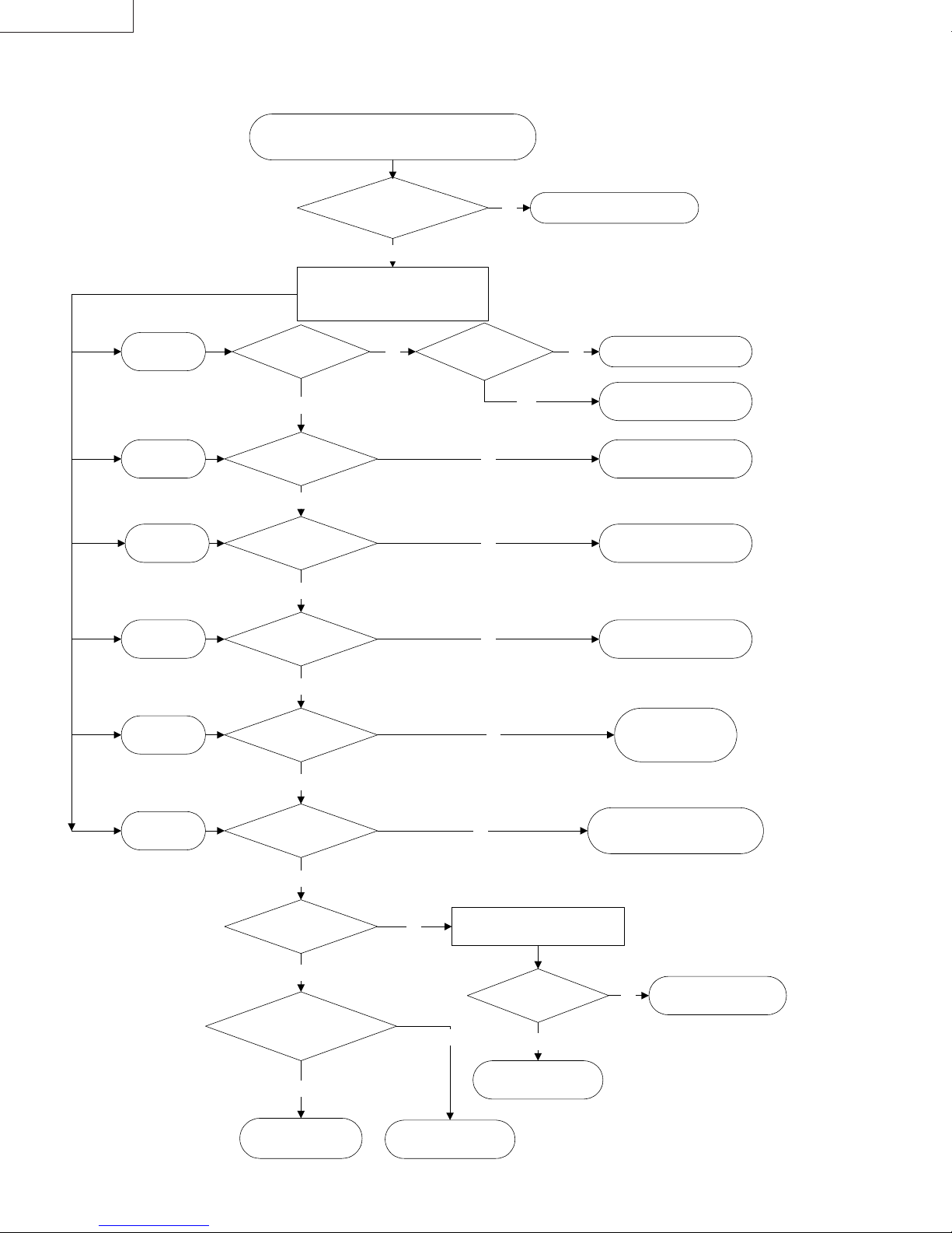
LX-D1010G
IC953 is failed,
IC904 is failed,
switches.
Z952 or Z953 is failed.
IC9A1 or IC3A1
IC905 is failed,
connector
5) Power system 3
When the self-diagnosis function shows a switched power
(SW5D, SW3.3, SW15.5, SW12, SW5A, SW9AU) short.
When the
SW5D failure
When the
SW3.3 failure
When the
SW15.5 failure
When the
SW12 failure
NF-SF GN-NN and GV-SV leads
Remove the Main PWB Ass'y and then
connect the Lamp-on Tool. Check the
Power and Power Sub PWB Ass'y.
Is there
5V or more at the CN:
NF-pin 8?
Yes
Is there
3.3V or more at the CN:
NF-pin 10?
Yes
Is there
15.5V or more at the CN:
RD-pin 2?
Yes
Is there
12V or more at the CN:
RD-pin 4?
Are the RD-SD,
conducting?
Yes
No Connect or replace the leads.
Turn on the POWER-ON
and FAN-ON
Is there
2V or more at the CN:
RB-pin 2?
Yes
No
No
No
No
The around of Q906 ia failed.No
Q952 or Q953 is failed,
or the around circuit short.
or the around circuit short.
or the around circuit short.
or the around circuit short.
When the
SW5A failure
When the
SW9AU failure
Yes
Is there
5V or more at the CN: RD-
pin 6?
Yes
Is there
14V or more at the CN:
RB-pin 5?
Yes
Is there
9V or more at the CN: GV-
pin 2?
Yes
If you replace the
Main PWB Ass'y, is the problem
disappaered?
Yes
The Main PWB Ass'y
failurre
No
No
The Video PWB Ass'y
Disconnect the NN
from the Power Sub PWB Ass'y.
No
failure
No
Is there
9V or more at the CN:
NN-pin 2?
Yes
The Audio PWB Ass'y
failure
Q907 is failed,
or the around circuit
of the IC906 short.
Check the around circuit of the IC952,
No
etc.
IC3A1 is failed,
or the around circuit short.
12-6 (PA012)
Page 57

6) Power system 4
Connect or replace
the connectors.
Check the around circuit
LX-D1010G
The lamp does not light
Are the RE and SA
connectors no problem?
Yes
Remove the Main PWB Ass'y
and then connect the Lamp-on Tool.
Turn on the POWER-ON, FAN-ON and LAMP-ON switches.
Does the lamp light?
Yes
Disconnect the RE lead and then
turn on the FAN-ON switch.
Is there 399V
or more between pin 1 and 3 of
the CN: RE?
No
Yes
No
The Main PWB Ass'y
failure
The Lamp Power Unit failure
No
Is there 20V
between both leads of the
Z900?
Yes
PFC circuit failure.
Check the around circuit
of the IC901 and Q900.
No
of the IC902 and PC901.
(PA012) 12-7
Page 58

LX-D1010G
(
)
pprop
y
7) Video system
When the video does not appear normall
Is the Menu
display normal?
Yes
No
Check the Lamp lighted.
!!!!
Check the indicator lights norm ally when the main
!!!!
power switch is turned on.
POWER: Green, LAMP: Green
Check that the input signal is normally and
!!!!
riate.
a
The Drive Circuit failure
・
Check the waveform at each terminal of the SRX,
SGX and SBX connectors.
・
Check the video signal line around IC800-804,
IC8A0-8A4 and IC8M0-8M4D.
・
Check the panel-control line around IC5A0-5A4.
※
If the waveforms are normally, the LCD Panel is
failed.
※
If input signal is displayed normally and Menu
display is abnormal, check the around of the
SGRAM: IC4S0.
Is the input video signal
displayed normally?
No
Is the input computer
signal displayed normally?
No
The digital signal process circuit is failed.
・
Check the digital signal line around of the IC400.
(SGRAM R: IC4J0, IC4P0, G: IC4G0, IC4M0, B: IC4H0, IC4N0)
Yes
Yes
The input analog circuit
for the computer terminal is failed.
・
Check the video signal line around J200 and
IC600.
・
Check the sync signal line around J200, IC240,
IC500, IC530, and IC600.
The input analog circuit
for the video terminal is failed.
・
Check the video signal line of the Video PWB
Ass’y.
・
Check the around of the IC2A2.
・
There is no problem if the shield metal is used for the secondary terminal voltage and ground (GND) during waveform
monitoring.
・
Adjust based on 7. Circuit Adjustment Method (refer to page 7-1) and 4. Removing Major Parts (refer to page 4-8)
when either the Main PWB Ass’y or the part of the Optical Ass’y has been replaced.
12-8 (PA012)
Page 59

LX-D1010G
A
13. LEAD WIRE WIRING DIAGRAM
Clamp the lead wires along the clamping zone shown in the diagram below.
The clamping zone indicates where the lead wires are to be routed and clamped.
Cautions
* The inner wires are clamped so that they do not come close to heat generating or high voltage parts. After servicing
route all wires in their original position.
* Workers shall put on the wristband to protect LCD Panel against static electricity during the operations.
Clamping zone
Hidden clamping zone
Lead dress in the Bottom Case Unit
Cushion
Cushion
Cushion
Lead wire
Cushion
Power Earth
Power Earth
There should be no slack in the lead
wire when the cushion is stuck.
Micro Switch
Inlet Earth
A
Micro Switch
Cushion
Bend the rest of the
cushion back.
Cushion
The lead wire should be fixed
firmly by the cushion.
(PA012) 13-1
Page 60

LX-D1010G
A
Lead dress when attaching each part
Cushion
Stick the cushion pulling the
wire toward the left to take in
slack in the wires.
Put the wire into the
gap to take in slack.
Cushion
Lead holder
to SN
SFSD
to SZto SF
SZ SW
SBX
Put the thick lead wire from the
lamp power into the gap so that it
never sticks out of the barrier. Do
not run this lead wire into the Power
ss’y in order to secure an air duct.
Put the wire into the
gap to take in slack.
SN
The NN-GN lead wire
should cross the SA-CB2
lead wire.
Run this earth wire above
the SY and SV lead wires.
Run the GN lead wire
under the SY lead wire.
Cushion
to Power Ass’y
SY
SV
SGX
SRX
Cushion
ST
SX
SL
Yellow-Green lead
The wire put into the
gap should not interfere
the lighting part and the
screw.
Do not position the wires
higher than the Main PWB.
13-2 (PA012)
Page 61

LX-D1010G
14. CONNECTOR TERMINAL FUNCTIONS
1) Main PWB Assy
E To Lamp Power Unit
Connector
SA-CB2 Signal Name IN / OUT Function / Summary Remark
1 LAMPON OUT Lamp on signal (H: ON) H: 4V / L: 0V
2 DGND
3 LSENSE IN
E To Power PWB Assy
Connector
SA-CB2 Signal Name IN / OUT Function / Summary Remark
1 AGND
2 SW15.5 IN Switched Power 15.5V 15.5V
3 AGND
4 SW12 IN Switched Power 12V 12V
5 AGND
6 SW5A IN Switched Power 5V 5V
7 AGND
8 STBYR5 IN Standby Power -5V -5V
9 AC-DOWN IN Power failure detect
10 P-ON OUT P-ON signal ( H: POWER OFF, L: POWER ON ) H: 5V / L: 0V
11 FAN-ON OUT FAN-ON signal (H: FAN ON, L: FAN OFF) H: 5V / L: 0V
12
13
Lamp-on was failed (C: failed, L: succeeded)
L: 0V (failed H: 5V)
E To Power Sub PWB Assy
Connector
SA-CB2 Signal Name IN / OUT Function / Summary Remark
1 FGND GND for fans
2 FANV IN Power for FAN 7-13V
3 P-FANC OUT POWER FAN CONTROL 0-4V
4 O-FANC OUT OPTICAL FAN CONTROL 0-4V
5 DGND GND for digital circuit
6 STBY5 IN Standby Power 5V DC 5V
7 DGND GND for digital circuit
8 SW5D IN Switched Power 5V 5V
9 DGND GND for digital circuit
10 SW3.3 IN Switched Power DC 3.3V 3.3V
11 P-FSTOP IN FAN LOCK SENSOR for power fan (L: normal, H: abnormal)
12
E To Blower (intake)
Connector
SA-CB2 Signal Name IN / OUT Function / Summary Remark
1 IN-FGND GND for Blower
2 IN-FANV OUT Power for Blower 7-13V
3 IN-FSTOP IN Fan lock sensor for Blower (L: normal / H: abnormal) 0V / 5V
(PA012) 14-1
Page 62

LX-D1010G
E To Fan Assy (exhaust)
Connector
SA-CB2 Signal Name IN / OUT Function / Summary Remark
1 OUT-FGND GND for Fan Assy (exhaust)
2 OUT-FANV Power for Fan Assy (exhaust) 7-13V
3 OUT-FSTOP IN Fan lock sensor for Fan Assy (L: normal / H: abnormal) 0V / 5V
E To Fan (small)
Connector
SA-CB2 Signal Name IN / OUT Function / Summary Remark
1 PBS-FGND GND for Fan (small) 7-13V
2 PBS-FANV Power for Fan (small) 11 / 12 / 13V
3 PBS-FSTOP IN Fan lock sensor for Fan (small) (L: normal / H: abnormal) 0V / 5V
4
E To Audio PWB Assy
Connector
SA-CB2 Signal Name IN / OUT Function / Summary Remark
1 GND-AU GND for audio circuit
2 SW9AU IN Switched power 9V for audio circuit 9V
3 VOL OUT Audio control 0-5V
4 S-MUTE Audio muting signal, muting: L 0V / 5V
5 AULRM Audio output 1Vp-p
6 GND-AU GND for audio circuit
7 DGND GND for digital circuit
8 RSI0 IN Remote control serial signal (rear)(L: sending data) H: 5V / L: 0V
9 STBY5 OUT Standby Power 5V DC 5V
E To Preamp PWB Assy
Connector
SA-CB2 Signal Name IN / OUT Function / Summary Remark
1 DGND
2 RSI1 IN Remote control serial signal (front)(L: sending data) H: 5V / L: 0V
3 STBY5 OUT Power STBY5 for remote control photoreceptor 5V
E To Video PWB Assy
Connector
SA-CB2 Signal Name IN / OUT Function / Summary Remark
1 AGND
2 SW5A IN Switched power 5V 5V
3 COMP/S IN Composite signal 1Vp-p
4 C IN Chroma signal (S-video input) 0.286Vp-p
5 AGND
6 Y IN Luminance signal 1Vp-p
7 AGND
8 DLEY IN Video signal 2Vp-p
9 AGND
10 COMP IN Composite signal 1Vp-p
11 AGND
12 AULR IN L / R audio input 1Vp-p
14-2 (PA012)
Page 63

E To CPU Test
Connector
SA-CB2 Signal Name IN / OUT Function / Summary Remark
1 DGND
2 SWFP/MOD IN Microcomputer operation mode setting Normal: L 0V
3 SWRSTZ IN Microcomputer reset signal Normal: H 5V
4 SWCLK IN Clock input for microcomputer writing Normal: H 5V
5 SWRXD IN Data input for microcomputer writing Normal: H 5V
6 SWTXD OUT Data output for microcomputer writing Normal: H 5V
7 SWBUSY IN Transmit / receive control Normal: H 5V
8 SWVCC OUT Power for writer 5V
9
10
E To Operation Unit
Connector
SA-CB2 Signal Name IN / OUT Function / Summary Remark
1 DGND
2 KEY0 IN For key input control
3 KEY1 IN For key input control
4 KEY2 IN For key input control
5 LED5V OUT Power 5V for LED
6 DGND
7 LEDPGZ OUT POWER LED (Green) control signal (LED-on: L) H: 3.3V / L: 0V
8 LEDPRZ OUT POWER LED (Red) control signal (LED-on: L) H: 3.3V / L: 0V
9 LEDTRZ OUT TEMP LED (Red) control signal (LED-on: L) H: 3.3V / L: 0V
10 LEDLGZ OUT LAMP LED (Green) control signal (LED-on: L) H: 3.3V / L: 0V
11 LEDLRZ OUT LAMP LED (Red) control signal (LED-on: L) H: 3.3V / L: 0V
12 LEDTGZ OUT TEMP LED (Green) control signal (LED-on: L) H: 3.3V / L: 0V
LX-D1010G
5V (
not operate
not operate
5V (
5V (
not operate
)
)
)
E To Thermistor Assy
Connector
SA-CB2 Signal Name IN / OUT Function / Summary Remark
1 DGND
2 TMP-LMP IN Lamp temperature detect
3 DGND
4 TMP-LCD IN LCD temperature detect 0V
5 DGND
6 TMP-IN IN Intake air temperature detect
7 DGND
8 PRT-TMP IN For connector disconnecting detect 0V
E To Lamp Cover and Filter Cover Switches
Connector
SA-CB2 Signal Name IN / OUT Function / Summary Remark
1 LAMP-ON IN Signal for force off of lamp on signal 0V / 5V
2 DGND GND for digital circuit
3 LBX IN Signal for lamp box sensor 0V / 5V
4 DGND GND for digital circuit
5 FBX IN Signal for filter box sensor (intake) 0V / 5V
0`5V
0`5V
(PA012) 14-3
Page 64

LX-D1010G
E To LCD Panel (R)
Connector
SA-CB2 Signal Name IN / OUT Function / Summary Remark
1 AGND Negative power for Y driver (GND) GND
2 RDIRY OUT Y driver drive direction reverse signal (floor: L, ceiling: H) L= 0V, H= 15.5V
3 RDY OUT Start pulse of Y shift resistor 0-15.5V, 1V (72.5Hz)
4 RLCCOM OUT COM voltage of LCD Panel (R)
5 RNRS1 OUT Assist signal of LCD Panel (R) 2-7.8V, reverse every 1H (56.8kHz)
6 RVID12 OUT R video signal 2-12V, reverse every 1H (56.8kHz)
7 RVID11 OUT R video signal 2-12V, reverse every 1H (56.8kHz)
8 RVID10 OUT R video signal 2-12V, reverse every 1H (56.8kHz)
9 RVID9 OUT R video signal 2-12V, reverse every 1H (56.8kHz)
10 RVID8 OUT R video signal 2-12V, reverse every 1H (56.8kHz)
11 RVID7 OUT R video signal 2-12V, reverse every 1H (56.8kHz)
12 RVID6 OUT R video signal 2-12V, reverse every 1H (56.8kHz)
13 RVID5 OUT R video signal 2-12V, reverse every 1H (56.8kHz)
14 RVID4 OUT R video signal 2-12V, reverse every 1H (56.8kHz)
15 RVID3 OUT R video signal 2-12V, reverse every 1H (56.8kHz)
16 RVID2 OUT R video signal 2-12V, reverse every 1H (56.8kHz)
17 RVID1 OUT R video signal 2-12V, reverse every 1H (56.8kHz)
18 AGND Negative power for X driver (GND) GND
19 RDIRX OUT X driver drive direction reverse signal (front: L, rear: H) L= 0V, H= 15.5V
20 RENBX1 OUT X driver enable pulse 0-15.5V, 3.125MHz
21 RENBX2 OUT X driver enable pulse 0-15.5V, 3.125MHz
22 RDX OUT Start pulse of X shift resistor 0-15.5V, 1H (56.8kHz)
23 RCLX OUT Transmit clock of X shift resistor 0-15.5V, 3.125MHz
24 RCLXZ OUT Transmit clock of X shift resistor (reverse signal of RCLX) 0-15.5V, 3.125MHz
25 RVDD OUT Positive power for X driver 15.5V
26 RVDD OUT Positive power for Y driver 15.5V
27 RNRG OUT Drive signal of assist signal circuit 0-15.5V, 1H (56.8kHz)
28 RCLY OUT Transmit clock of Y shift resistor 0-15.5V, reverse every 1H (56.8kHz)
29 RCLYZ OUT Transmit clock of Y shift resistor (reverse signal of RCLY) 0-15.5V, reverse every 1H (56.8kHz)
30 RDY OUT Start pulse of Y shift resistor 0-15.5V, 1V (72.5Hz)
6
}
0.5V
E To LCD Panel (G)
Connector
SA-CB2 Signal Name IN / OUT Function / Summary Remark
1GDY OUT
2 GCLYZ OUT Transmit clock of Y shift resistor (reverse signal of GCLY) 0-15.5V, reverse every 1H (56.8kHz)
3 GCLY OUT Transmit clock of Y shift resistor 0-15.5V, reverse every 1H (56.8kHz)
4 GNRG OUT Drive signal of assist signal circuit 0-15.5V, 1H (56.8kHz)
5 GVDD OUT Positive power for Y driver 15.5V
6 GVDD OUT Positive power for X driver 15.5V
7 GCLXZ OUT Transmit clock of X shift resistor (reverse signal of GCLX) 0-15.5V, 3.125MHz
8 GCLX OUT Transmit clock of X shift resistor 0-15.5V, 3.125MHz
9 GDX OUT Start pulse of X shift resistor 0-15.5V, 1H (56.8kHz)
10 GENBX2 OUT X driver enable pulse 0-15.5V, 3.125MHz
11 GENBX1 OUT X driver enable pulse 0-15.5V, 3.125MHz
12 GDIRX OUT X driver drive direction reverse signal (front: L, rear: H) L= 0V, H= 15.5V
13 AGND Negative power for X driver (GND) GND
14 GVID1 OUT G video signal 2-12V, reverse every 1H (56.8kHz)
15 GVID2 OUT G video signal 2-12V, reverse every 1H (56.8kHz)
16 GVID3 OUT G video signal 2-12V, reverse every 1H (56.8kHz)
17 GVID4 OUT G video signal 2-12V, reverse every 1H (56.8kHz)
18 GVID5 OUT G video signal 2-12V, reverse every 1H (56.8kHz)
19 GVID6 OUT G video signal 2-12V, reverse every 1H (56.8kHz)
20 GVID7 OUT G video signal 2-12V, reverse every 1H (56.8kHz)
21 GVID8 OUT G video signal 2-12V, reverse every 1H (56.8kHz)
22 GVID9 OUT G video signal 2-12V, reverse every 1H (56.8kHz)
23 GVID10 OUT G video signal 2-12V, reverse every 1H (56.8kHz)
24 GVID11 OUT G video signal 2-12V, reverse every 1H (56.8kHz)
25 GVID12 OUT G video signal 2-12V, reverse every 1H (56.8kHz)
26 GNRS1 OUT Assist signal of LCD Panel (G) 2-7.8V, reverse every 1H (56.8kHz)
27 GLCCOM OUT COM voltage of LCD Panel (G)
28 GDY OUT Start pulse of Y shift resistor 0-15.5V, 1V (72.5Hz)
29 GDIRY OUT Y driver drive direction reverse signal (floor: L, ceiling: H) L= 0V, H= 15.5V
30 AGND Negative power for Y driver (GND) GND
Start pulse of N shift resistor
0-15.5V, 1V (72.5Hz)
6
}
0.5V
14-4 (PA012)
Page 65

LX-D1010G
E To LCD Panel (B)
Connector
SA-CB2 Signal Name IN / OUT Function / Summary Remark
1 AGND Negative power for Y driver (GND) GND
2 BDIRY OUT Y driver drive direction reverse signal (floor: L, ceiling: H) L= 0V, H= 15.5V
3 BDY OUT Start pulse of Y shift resistor 0-15.5V, 1V (72.5Hz)
4 BLCCOM OUT COM voltage of LCD Panel (B)
5 BNRS1 OUT Assist signal of LCD Panel (B) 2-7.8V, reverse every 1H (56.8kHz)
6 BVID12 OUT B video signal 2-12V, reverse every 1H (56.8kHz)
7 BVID11 OUT B video signal 2-12V, reverse every 1H (56.8kHz)
8 BVID10 OUT B video signal 2-12V, reverse every 1H (56.8kHz)
9 BVID9 OUT B video signal 2-12V, reverse every 1H (56.8kHz)
10 BVID8 OUT B video signal 2-12V, reverse every 1H (56.8kHz)
11 BVID7 OUT B video signal 2-12V, reverse every 1H (56.8kHz)
12 BVID6 OUT B video signal 2-12V, reverse every 1H (56.8kHz)
13 BVID5 OUT B video signal 2-12V, reverse every 1H (56.8kHz)
14 BVID4 OUT B video signal 2-12V, reverse every 1H (56.8kHz)
15 BVID3 OUT B video signal 2-12V, reverse every 1H (56.8kHz)
16 BVID2 OUT B video signal 2-12V, reverse every 1H (56.8kHz)
17 BVID1 OUT B video signal 2-12V, reverse every 1H (56.8kHz)
18 AGND Negative power for X driver (GND) GND
19 BDIRX OUT X driver drive direction reverse signal (front: L, rear: H) L= 0V, H= 15.5V
20 BENBX1 OUT X driver enable pulse 0-15.5V, 3.125MHz
21 BENBX2 OUT X driver enable pulse 0-15.5V, 3.125MHz
22 BDX OUT Start pulse of X shift resistor 0-15.5V, 1H (56.8kHz)
23 BCLX OUT Transmit clock of X shift resistor 0-15.5V, 3.125MHz
24 BCLXZ OUT Transmit clock of X shift resistor (reverse signal of BCLX) 0-15.5V, 3.125MHz
25 BVDD OUT Positive power for X driver 15.5V
26 BVDD OUT Positive power for Y driver 15.5V
27 BNRG OUT Drive signal of assist signal circuit 0-15.5V, 1H (56.8kHz)
28 BCLY OUT Transmit clock of Y shift resistor 0-15.5V, reverse every 1H (56.8kHz)
29 BCLYZ OUT Transmit clock of Y shift resistor (reverse signal of BCLY) 0-15.5V, reverse every 1H (56.8kHz)
30 BDY OUT Start pulse of Y shift resistor 0-15.5V, 1V (72.5Hz)
6
}0.5V
(PA012) 14-5
Page 66

LX-D1010G
2) Power PWB Assy
E To Lamp Power Unit
Connector
SA-CB2 Signal Name IN / OUT Function / Summary Remark
1 L399V OUT PFC circuit output DC 399V
2
3 LGND Primary GND
E To Thermal Protector / Inlet Switch PWB Assy
Connector
SA-CB2 Signal Name IN / OUT Function / Summary Remark
1 LIVE IN AC
2
3
4 NUT IN AC
E To Power Sub PWB Assy
Connector
SA-CB2 Signal Name IN / OUT Function / Summary Remark
1 DGND GND for digital circuit
2 POWER-ON OUT POWER ON signal (H: ON, L: OFF) H: 5V / L:0V
3 FAN-ON OUT FAN-ON signal (H: FAN ON, L: FAN OFF) H: 5V / L: 0V
4 FGND GND for FAN
5 14V OUT Secondary output voltage (14V) DC 14V
6 DGND GND for digital circuit
7 STBY5 OUT Standby 5V DC 5V
3) Power Sub PWB Assy
E To Intake Fan (front)
Connector
SA-CB2 Signal Name IN / OUT Function / Summary Remark
1 FGND GND for FAN
2 FANP OUT Power for Intake Fan (front) 7-13V
3 P-FSTOP IN Fan lock sensor for Intake Fan (front) (L: normal / H: abnormal)
E To Audio PWB Assy
Connector
SA-CB2 Signal Name IN / OUT Function / Summary Remark
1 AUGND GND for audio
2 AU9V OUT Power for audio DC 9V
4) Power Sub PWB Assy
E To Speaker
Connector
SA-CB2 Signal Name IN / OUT Function / Summary Remark
1 SPGND GND for Speaker
2 SPK OUT Speaker output
3
14-6 (PA012)
Page 67

15. BLOCK DIAGRAMS
LX-D1010G
(PA012) 15-1
Page 68

(PA012) 15-2
LX-D1010G
Page 69

LX-D1010G
(PA012) 15-3
Page 70

LX-D1010G
(PA012) 16-1
Page 71

PARTS LIST
Packing and Accessory Assembly
13, 14, 15, 17, 18, 19
LX-D1010G
16
2, 3, 4, 5, 6, 9, 10
1
8
12
7
11
Packing Parts List
REF
No.
1 M-802B716O10 ACCESSORY CASE 11 M-802B755O10 PACKING CASE (LX-D1010G)
2 M-246C383O10 AC POWER CORD 12 M-831D190O10 PACKING SHEET
3 M-246C383O20 AC POWER CORD (for Europe) 13 M-246C381O10 AV (Audio/Video) CABLE
4 M-246C367O10 PS/2 ADAPTOR 14 M-939P795O20 REMOTE CONTROLLER
5 M-246C382O10 PC RGB CABLE 15 - BATTERY for remote x 2
6 M-246C366O10 RS-232C CABLE 16 M-772P032O10 CARRYING CASE
7 M-803A558O10 CUSHION BOTTOM 17 M-246C376O10 USB CABLE
8 M-803A557O10 CUSHION TOP 18 M-246C384O10 S-VIDEO CABLE
9 M-871D294O10 INST BOOK (LX-D1010G) 19 M-411D024O40 CORE
10 M-831D181O20 PACKING BAG for Accessory
PART No. PART NAME, DESCRIPTION
REF
No.
PART No. PART NAME, DESCRIPTION
(PA012) Parts-1
Page 72

LX-D1010G
Final Assembly M 1
13
14
1
3
6
2
×
2
5
×
1
7
8
2
11
×
2
×
×
1
9
×
4
6
10
15 16
4
17
×
19
6
×
22
2
24
×
1
26
×
18
1
12
×
21
1
×
25
29
23
27
28
20
Parts-2 (PA012)
Page 73

Parts List (Final Assembly M 1 )
REF No. PART No. PART NAME, DESCRIPTION
1 M-759A003O40 TOP CASE ASS'Y
2 M-669D561O20
3 M-439C049O60 OPERATION UNIT
-
-
-
-
-
-
-
M-436P021O10
M-771C147O10
4
5 M-669D329O10
6
7 M-669D564O30
8 M-935D529O01 PREAMP PWB ASS'Y
9 M-669D564O30
10
11 M-669D329O10
12 M-669D561O20
13 M-939P794O10 LAMP POWER UNIT
14 M-669D564O30
15
16
17 M-669D564O40
18
19 M-669D564O30
20 M-752C251O30 LAMP COVER
21 M-669D425O20
22 M-761B364O10 LENS CAP
23 M-589B013O10 ADJUSTER
24 M-669D368O40
25
26 M-669D564O30
27 M-640D990O10 FILTER
28 M-752C250O30 FILTER COVER
29 M-759A004O40 BOTTOM CASE UNIT
-
-
LX-D1010G
SCREW×6
INLET EARTH
SCREW×2
METAL BOARD A
SCREW×1
SCREW×1
(MAIN PWB, VIDEO PWB, INLET SWITCH PWB AND TERMINAL BORD) ASS’Y
SCREW×2
SCREW×1
SCREW×2
METAL BOARD B
OPTICAL ASS'Y
SCREW×4
POWER ASS’Y
SCREW×6
SCREW×1
SCREW×2
AUDIO ASS’Y
SCREW×1
MICRO SWITCH×2 (refer to page 13-1)
ADJUSTER(R)×2 (rear foot)
(PA012) Parts-3
Page 74

LX-D1010G
(Main PWB, Video PWB, Inlet Switch PWB and Terminal Board) Ass’y M 2
1
8
10
14
12
1
2
×
4
4
×
2
3
×
1
9
×
11
×
5
Parts List (Main PWB, Video PWB, Inlet Switch PWB and Terminal Board Ass’y M 2 )
Soldering
13
3
2
7
×
3
6
×
REF No. PART No. PART NAME, DESCRIPTION
1 M-935B259O09 MAIN PWB ASS'Y
2 M-669D329O10
3 M-669D199O30
4 M-669D552O10
SCREW×1
SCREW×2
SCREW×4
5 M-761B363O40 TERMINAL BOARD
SCREW×3
SCREW×2
SCREW×1
SCREW×3
PIN SHIELD
FPC CONNECTOR (R,B)×2 (SRX and SBX, refer to page 13-2)
6 M-669D199O30
7 M-669D566O10
8 M-935C922O09 INLET SWITCH PWB ASS'Y
9 M-669D245O10
10 M-935C920O01 VIDEO PWB ASS'Y
11 M-669D212O20
12
-
13 M-433C026O40 POWER SWITCH
14 M-283D107O30 FUSE (F9F1)
-
-
M-452C247O20
M-452C233O20 FPC CONNECTOR (G) (SGX, refer to page 13-2)
Parts-4 (PA012)
Page 75

Power Ass’y M 3
LX-D1010G
4
6
5
7
1
2
×
1
10
3
Parts List (Power Ass’y M 3 )
REF
No.
1
PART No. PART NAME, DESCRIPTION
-
2 M-669D329O10
3
-
SUB POWER HOLDER
SCREW×1
POWER BARRIER 8 M-288P160O50 FAN
REF
No.
6 M-935C921O01 POWER SUB PWB ASS'Y
7 M-621C827O10 POWER HOLDER (F)
4 M-621C828O10 POWER HOLDER (R) 9 M-669D220O70
5 M-935B260O01 POWER PWB ASS'Y
10 M-299P194O20 THERMOSTAT (Z900)
2
9
×
8
PART No. PART NAME, DESCRIPTION
SCREW×2
(PA012) Parts-5
Page 76

LX-D1010G
Audio Ass’y M 4
×
2
Parts List (Audio Ass’y M 4 )
Parts-6 (PA012)
REF No. PART No. PART NAME, DESCRIPTION
1 M-480P052O10 SPEAKER
SCREW×2
AUDIO HOLDER
SCREW×1
2 M-650P200O60
3
4 M-935C923O01 AUDIO PWB ASS'Y
5 M-669D329O10
-
×
1
Page 77

Memo
LX-D1010G
(PA012) Parts-7
Page 78

LX-D1010G
Optical Ass’y M 5
23
2
2
×
2
4
×
8
5
×
1
2
4
×
22
2
4
×
2
×
2
7
×
3
6
19
21
1
×
8
20
13
13
12
4
×
18
9
×
13
3
10
16
2
11
×
14
2
17
×
Parts-8 (PA012)
15
6
×
Page 79

Parts List (Optical Ass’y M 5 )
REF No. PART No. PART NAME, DESCRIPTION
1 M-499D007O70
2 M-669D212O30
3
4 M-669D540O20
5 M-669D212O10
6 M-499D008O10 THERMAL PROTECTOR
7 M-669D220O10
8 M-499D007O10 LCD BLOCK
9 M-669D329O10
10 M-499D007O50
11 Attached to No.10
12
13 M-669D329O10
14
15 M-669D317O10
16 M-499D007O30-SA LAMP ASS'Y
17 Attached to No.16
18 M-499D007O20 LENS UNIT
19 M-669D329O20
20 M-499D007O90 THERMISTOR ASS’Y
21 M-669D220O10
22 M-499D007O60
23 Attached to No.22
-
-
-
FAN (Small
SCREW×2
OPTICAL COVER
SCREW×6
SCREW×8
SCREW×2
SCREW×3
BLOWER (Intake
SCREW×2
BLOWER HOLDER
SCREW×3
COOLING COVER
SCREW×6
SCREW×2
SCREW×4
SCREW×1
FAN ASS'Y (Exhaust
SCREW×2
)
)
)
LX-D1010G
(PA012) Parts-9
Page 80

LX-D1010G
Inside of the Optical Ass’y M 6
2
1
Install Direction Light source side (Lamp side)
PBS
Parts List (Inside of the Optical Ass’y M 6 )
REF No. PART No. PART NAME, DESCRIPTION
1 M-499D007O80 PBS ASS’Y
2 M-499D007O40 POLARIZER (R, G, B)
Parts-10 (PA012)
Plane
Uneven
POLARIZER(R, G, B)
Plane
Film side
Projection lens side
Page 81

しろページ
Page 82

VICTOR COMPANY OF JAP AN, LIMITED
Projection System Department 1644 Shimotsuruma, Yamato, Kanagawa, 242-8514, Japan
LX-D1010G Printed in Japan
VP 0002
K.K
 Loading...