

JVC LT-52X579, LT-52X579KA Service Manual
SERVICE MANUAL
YA654<Rev.001>20089SERVICE MANUAL
LCD FLAT TELEVISION
LT-52X579/KA
BASIC CHASSIS
FN3
There may be multiple versions of
this TV model.
The TV version is identified by the
letters next to the model number
on the TVs Rating and Model No.
labels. (See illustration).
Use the service manual that
matches the version of the TV.
COPYRIGHT © 2008 Victor Company of Japan, Limited
No.YA590: LT-32P679 No.YA589: LT-42P789 No.YA591: LT-47P789
No.YA592
No.YA653
: LT-32E479, LT-32EM49 No.YA593: LT-42X579, LT-42EM59 No.YA594: LT-47X579, LT-47EM59
: LT-52P789 No.YA654: LT-52X579
MODEL NAME
LT-52X579
<FN3 CHASSIS LINEUP>
MODEL NO.
RATING LABEL (REAR)
MODEL NO. LABEL (SIDE)
TABLE OF CONTENTS
1 PRECAUTION. . . . . . . . . . . . . . . . . . . . . . . . . . . . . . . . . . . . . . . . . . . . . . . . . . . . . . . . . . . . . . . . . . . . . . . . . 1-3
2 SPECIFIC SERVICE INSTRUCTIONS . . . . . . . . . . . . . . . . . . . . . . . . . . . . . . . . . . . . . . . . . . . . . . . . . . . . . . 1-5
3 DISASSEMBLY . . . . . . . . . . . . . . . . . . . . . . . . . . . . . . . . . . . . . . . . . . . . . . . . . . . . . . . . . . . . . . . . . . . . . . . 1-8
4 ADJUSTMENT . . . . . . . . . . . . . . . . . . . . . . . . . . . . . . . . . . . . . . . . . . . . . . . . . . . . . . . . . . . . . . . . . . . . . . . 1-14
5 TROUBLESHOOTING . . . . . . . . . . . . . . . . . . . . . . . . . . . . . . . . . . . . . . . . . . . . . . . . . . . . . . . . . . . . . . . . . 1-16
VERSION
KAA
COPYRIGHT © 2008 Victor Company of Japan, Limited
No.YA654<Rev.001>
2008/9
SPECIFICATION
Items Contents
Dimensions ( W × H × D ) 125.8 cm × 87.57 cm × 34.57 cm (49-1/2" × 34-1/2" × 13-5/8") [with stand]
125.8 cm × 82.5 cm × 12.29 cm (49-1/2" × 32-1/2" × 4-13/16") [without stand]
Mass 34.0 kg (74.8 lbs) [with stand]
Power Input AC120 V , 60 Hz
Power Consumption 276W (Max)
TV RF System
(Analog / Digital)
Color System (Analog) NTSC
Stereo System (Analog) BTSC (Multi Channel Sound)
Teletext System (Analog) Closed caption (T1-T4 / CC1-CC4)
TV Receiving Channels
and Frequency (Analog)
TV / CATV Total Channel 191 Channels
Intermediate Frequency
(Analog)
Color Sub Carrier Frequency (Analog) 3.58 MHz
LCD Panel 52V-inch wide aspect (16:9)
Screen Size Diagonal: 132.17 cm (H: 115.2 cm × V: 64.8 cm)
Display Pixels Horizontal : 1920 dots × Vertical : 1080 dots
Audio Power Output 10 W + 10 W
Speaker 4.0 cm × 16.0 cm, oval type(Oblique corn) × 2
Antenna Terminal
(VHF/UHF, ATSC / DIGITAL CABLE IN)
Digital Input
[INPUT-1/2/3]
Video / Audio Input
[INPUT-4]
Video / Audio Input
[INPUT-5]
Audio output (Fix) 500 mV (rms), Low impedance, RCA pin jack × 2
Digital Audio Optical Output Digital SPDIF × 1
Photo Viewer / Service USB connector × 1
Remote Control Unit RM-C2050 (AA/R6 battery × 2)
Digital(Video/Audio) HDMI 2-row 19pin connector × 3
Component Video
Component Video
VHF Low
VHF High
Video IF
Sound IF
Analog (Audio) 500mV(rms) (-4dBs), high impedance, RCA pin jack × 2
1080i / 720p
480p / 480i
S-Video Mini-DIN 4 pin × 1
1080i / 720p
480p / 480i
Design & specifications are subject to change without notice.
29.7 kg (65.3 lbs) [without stand]
Analog
CCIR (M)
Digital
ATSC terrestrial / Digital cable
02 ch - 06 ch : 54 MHz - 88 MHz
07 ch - 13 ch : 174 MHz - 216 MHz
UHF
14 ch - 69 ch : 470 MHz - 806 MHz
CATV
54 MHz - 804 MHz
Low Band : 02 - 06
High Band : 07 - 13
Mid Band : 14 - 22
Super Band : 23 - 36
Hyper Band : 37 - 64
Ultra Band : 65 - 94, 100 - 135
Sub Mid Band : 01, 96 - 99
45.75 MHz
41.25 MHz (4.5 MHz)
F-type connector, 75Ω unbalanced, coaxial × 1
(Digital-input terminal is not compatible with picture signals of personal computer)
Video: Supported format: 1080p / 1080i / 720p / 480p / 480i
Audio: 2ch L-PCM, 32 / 44.1 / 48 KHz, 16 / 20 / 24 bit
RCA pin jack × 3
Y : 1 V (p-p) (Sync signal: 0.35V(p-p), 3-value sync.), 75 Ω
Pb/Pr : ±0.35V(p-p), 75 Ω
Y : 1 V (p-p), Positive (Negative sync.), 75 Ω
Cb/Cr : 0.7V(p-p), 75 Ω
Y: 1 V (p-p), Positive (Negative sync.), 75 Ω
C: 0.286V (p-p) (Burst signal), 75 Ω
Video 1 V (p-p), Positive (Negative sync.), 75 Ω, RCA pin jack × 1
Audio 500 mV (rms), High impedance, RCA pin jack × 2
RCA pin jack × 3
Y : 1 V (p-p) (Sync signal: 0.35V(p-p), 3-value sync.), 75 Ω
Pb/Pr : ±0.35V(p-p), 75 Ω
Y : 1 V (p-p), Positive (Negative sync.), 75 Ω
Cb/Cr : 0.7V(p-p), 75 Ω
Video 1 V (p-p), Positive (Negative sync.), 75 Ω, RCA pin jack × 1
Audio 500 mV (rms), High impedance, RCA pin jack × 2
1-2 (No.YA654<Rev.001>)
SECTION 1
PRECAUTION
1.1 SAFETY PRECAUTIONS
(1) The design of this product contains special hardware,
many circuits and components specially for safety
purposes. For continued protection, no changes should be
made to the original design unless authorized in writing by
the manufacturer. Replacement parts must be identical to
those used in the original circuits. Service should be
performed by qualified personnel only.
(2) Alterations of the design or circuitry of the products should
not be made. Any design alterations or additions will void
the manufacturer's warranty and will further relieve the
manufacturer of responsibility for personal injury or
property damage resulting therefrom.
(3) Many electrical and mechanical parts in the products have
special safety-related characteristics. These
characteristics are often not evident from visual inspection
nor can the protection afforded by them necessarily be
obtained by using replacement components rated for
higher voltage, wattage, etc. Replacement parts which
have these special safety characteristics are identified in
the parts list of Service manual. Electrical components
having such features are identified by shading on the
schematics and by ( ) on the parts list in Service
manual. The use of a substitute replacement which does
not have the same safety characteristics as the
recommended replacement part shown in the parts list of
Service manual may cause shock, fire, or other hazards.
(4) Don't short between the LIVE side ground and
ISOLATED (NEUTRAL) side ground or EARTH side
ground when repairing.
Some model's power circuit is partly different in the GND.
The difference of the GND is shown by the LIVE : ( ) side
GND, the ISOLATED (NEUTRAL) : ( ) side GND and
EARTH : ( ) side GND.
Don't short between the LIVE side GND and ISOLATED
(NEUTRAL) side GND or EARTH side GND and never
measure the LIVE side GND and ISOLATED (NEUTRAL)
side GND or EARTH side GND at the same time with a
measuring apparatus (oscilloscope etc.). If above note will
not be kept, a fuse or any parts will be broken.
(5) When service is required, observe the original lead dress.
Extra precaution should be given to assure correct lead
dress in the high voltage circuit area. Where a short circuit
has occurred, those components that indicate evidence of
overheating should be replaced. Always use the
manufacturer's replacement components.
(6) Isolation Check (Safety for Electrical Shock Hazard)
After re-assembling the product, always perform an
isolation check on the exposed metal parts of the cabinet
(antenna terminals, video/audio input and output terminals,
Control knobs, metal cabinet, screw heads, earphone jack,
control shafts, etc.) to be sure the product is safe to operate
without danger of electrical shock.
a) Dielectric Strength Test
The isolation between the AC primary circuit and all metal
parts exposed to the user, particularly any exposed metal
part having a return path to the chassis should withstand a
voltage of 3000V AC (r.m.s.) for a period of one second. (.
. . . Withstand a voltage of 1100V AC (r.m.s.) to an
appliance rated up to 120V, and 3000V AC (r.m.s.) to an
appliance rated 200V or more, for a period of one second.)
This method of test requires a test equipment not generally
found in the service trade.
b) Leakage Current Check
Plug the AC line cord directly into the AC outlet (do not use
a line isolation transformer during this check.). Using a
"Leakage Current Tester", measure the leakage current
from each exposed metal part of the cabinet, particularly
any exposed metal part having a return path to the chassis,
to a known good earth ground (water pipe, etc.). Any
leakage current must not exceed 0.5mA AC (r.m.s.).
However, in tropical area, this must not exceed 0.2mA AC
(r.m.s.).
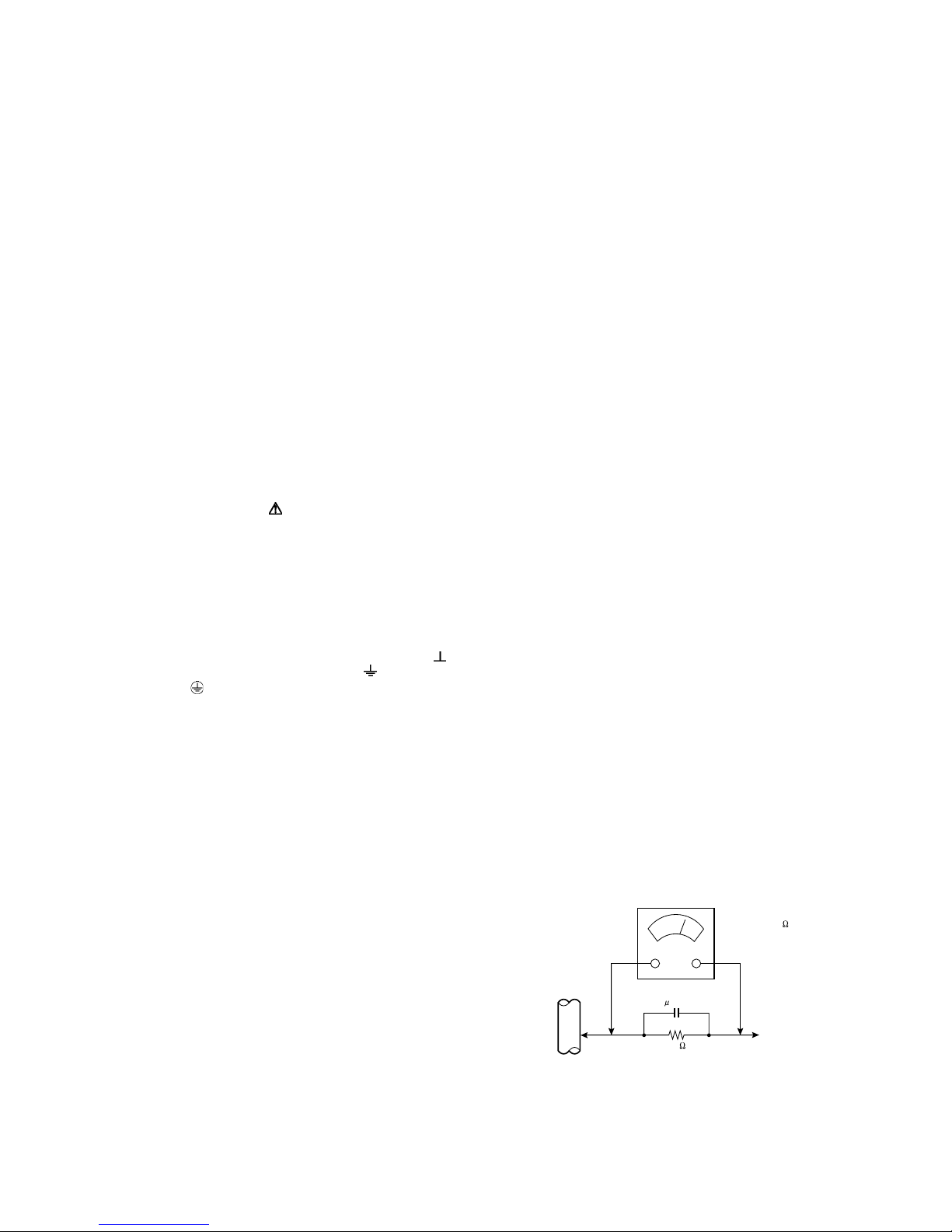
Alternate Check Method
Plug the AC line cord directly into the AC outlet (do not
use a line isolation transformer during this check.). Use
an AC voltmeter having 1000Ω per volt or more
sensitivity in the following manner. Connect a 1500Ω
10W resistor paralleled by a 0.15µF AC-type capacitor
between an exposed metal part and a known good earth
ground (water pipe, etc.). Measure the AC voltage
across the resistor with the AC voltmeter. Move the
resistor connection to each exposed metal part,
particularly any exposed metal part having a return path
to the chassis, and measure the AC voltage across the
resistor. Now, reverse the plug in the AC outlet and
repeat each measurement. Any voltage measured must
not exceed 0.75V AC (r.m.s.). This corresponds to
0.5mA AC (r.m.s.).
However, in tropical area, this must not exceed 0.35V
AC (r.m.s.). This corresponds to 0.3mA AC (r.m.s.).
AC VOLTMETER
(HAVING 1000 /V,
OR MORE SENSITIVITY)
0.15 F AC-TYPE
GOOD EARTH GROUND
1500 10W
PLACE THIS PROBE
ON EACH EXPOSED
ME TAL PAR T
(No.YA654<Rev.001>)1-3
1.2 INSTALLATION
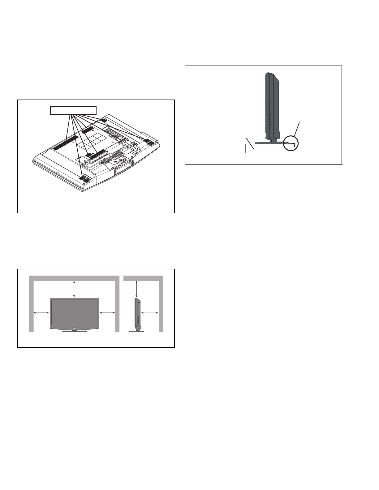
1.2.1 HEAT DISSIPATION
If the heat dissipation vent behind this unit is blocked, cooling
efficiency may deteriorate and temperature inside the unit will
rise. The temperature sensor that protects the unit will be
activated when internal temperature exceeds the pre-determined
level and power will be turned off automatically.Therefore,
please make sure pay attention not to block the heat dissipation
vent as well as the ventilation outlet behind the unit and ensure
that there is room for ventilation around it.
Ventilation hole
*The drawing may differ from the actual appearance.
1.2.3 INSTALLATION REQUIREMENTS
To ensure safety in an emergency such as an earthquake, and
to prevent accidents, ensure that measures are taken to prevent
the TV dropping or falling over.
It fixes in a band.
TV STAND
*The drawing may differ from the actual appearance.
1.2.4 NOTES ON HANDLING
When taking the unit out of a packing case, do not grasp the
upper part of the unit. If you take the unit out while grasping the
upper part, the LCD PANEL may be damaged because of a
pressure. Instead of grasping the upper part, put your hands on
the lower backside or sides of the unit.
1.2.2 INSTALLATION REQUIREMENTS
Ensure that the minimal distance is maintained, as specified
below, between the unit with and the surrounding walls, as well
as the floor etc.Install the unit on stable flooring or stands.Take
precautionary measures to prevent the unit from tipping in order
to protect against accidents and earthquakes.
200 mm
7 7/8 inch
150 mm
5 7/8 inch
*The drawing may differ from the actual appearance.
150 mm
5 7/8 inch
200 mm
7 7/8 inch
50 mm
2 inch
1.3 HANDLING LCD PANEL
1.3.1 PRECAUTIONS FOR TRANSPORTATION
When transporting the unit, pressure exerted on the internal LCD
panel due to improper handling (such as tossing and dropping)
may cause damages even when the unit is carefully packed. To
prevent accidents from occurring during transportation, pay
careful attention before delivery, such as through explaining the
handling instructions to transporters.
Ensure that the following requirements are met during
transportation, as the LCD panel of this unit is made of glass and
therefore fragile:
(1) USE A SPECIAL PACKING CASE FOR THE LCD PANEL
When transporting the LCD panel of the unit, use a special
packing case (packing materials). A special packing case
is used when a LCD panel is supplied as a service spare
part.
(2) ATTACH PROTECTION SHEET TO THE FRONT
Since the front (display part) of the panel is vulnerable,
attach the protection sheet to the front of the LCD panel
before transportation. Protection sheet is used when a LCD
panel is supplied as a service spare part.
(3) AVOID VIBRATIONS AND IMPACTS
The unit may be broken if it is toppled sideways even when
properly packed. Continuous vibration may shift the gap of
the panel, and the unit may not be able to display images
properly. Ensure that the unit is carried by at least 2
persons and pay careful attention not to exert any vibration
or impact on it.
(4) DO NOT PLACE EQUIPMENT HORIZONTALLY
Ensure that it is placed upright and not horizontally during
transportation and storage as the LCD panel is very
vulnerable to lateral impacts and may break. During
transportation, ensure that the unit is loaded along the
traveling direction of the vehicle, and avoid stacking them
on one another. For storage, ensure that they are stacked
in 2 layers or less even when placed upright.
1-4 (N o.YA 654<R ev.001>)

1.3.2 OPTICAL FILTER (ON THE FRONT OF THE LCD PANEL)
(1) Avoid placing the unit under direct sunlight over a
prolonged period of time. This may cause the optical filter
to deteriorate in quality and color.
(2) Clean the filter surface by wiping it softly and lightly with a
soft and lightly fuzz cloth (such as outing flannel).
(3) Do not use solvents such as benzene or thinner to wipe the
filter surface. This may cause the filter to deteriorate in
quality or the coating on the surface to come off. When
cleaning the filter, usually use the neutral detergent diluted
with water. When cleaning the dirty filter, use water-diluted
ethanol.
(4) Since the filter surface is fragile, do not scratch or hit it with
hard materials. Be careful enough not to touch the front
surface, especially when taking the unit out of the packing
case or during transportation.
SECTION 2
SPECIFIC SERVICE INSTRUCTIONS
2.1 FEATURES
Built in ATSC (Advanced Television Systems Committee)
TUNER
This TV can receive both Digital broadcasting (ATSC) and
Analog broadcasting.
Color Management
This function ensures dull colors are compensated to produce
natural hues.
1.3.3 PRECAUTIONS FOR REPLACEMENT OF EXTERIOR
PARTS
Take note of the following when replacing exterior parts (REAR
COVER, FRONT PANEL, etc.):
(1) Do not exert pressure on the front of the LCD panel (filter
surface). It may cause irregular color.
(2) Pay careful attention not to scratch or stain the front of the
LCD panel (filter surface) with hands.
(3) When replacing exterior parts, the front (LCD panel) should
be placed facing downward. Place a mat, etc. underneath
to avoid causing scratches to the front (filter surface).
Smart Picture
This function detects the APL (Average Picture Level) and
adjusts the contrast suitable for what you are watching.
DIGITAL VNR
This function cuts down the amount of noise in the original
picture.
MPEG Noise Reduction
This function effects the block noise removal and mosquito NR
simultaneously.
(No.YA654<Rev.001>)1-5
 Loading...