

Page 1

SERVICE MANUAL
WIDE LCD PANEL TELEVISION
YA306200510
LT-15B60SJ,
LT-15B60SW
TABLE OF CONTENTS
1 PRECAUTION. . . . . . . . . . . . . . . . . . . . . . . . . . . . . . . . . . . . . . . . . . . . . . . . . . . . . . . . . . . . . . . . . . . . . . . . . 1-3
2 SPECIFIC SERVICE INSTRUCTIONS . . . . . . . . . . . . . . . . . . . . . . . . . . . . . . . . . . . . . . . . . . . . . . . . . . . . . . 1-7
3 DISASSEMBLY . . . . . . . . . . . . . . . . . . . . . . . . . . . . . . . . . . . . . . . . . . . . . . . . . . . . . . . . . . . . . . . . . . . . . . 1-12
4 ADJUSTMENT . . . . . . . . . . . . . . . . . . . . . . . . . . . . . . . . . . . . . . . . . . . . . . . . . . . . . . . . . . . . . . . . . . . . . . . 1-16
5 TROUBLESHOOTING . . . . . . . . . . . . . . . . . . . . . . . . . . . . . . . . . . . . . . . . . . . . . . . . . . . . . . . . . . . . . . . . . 1-16
COPYRIGHT © 2005 Victor Company of Japan, Limited
No.YA306
2005/10
Page 2
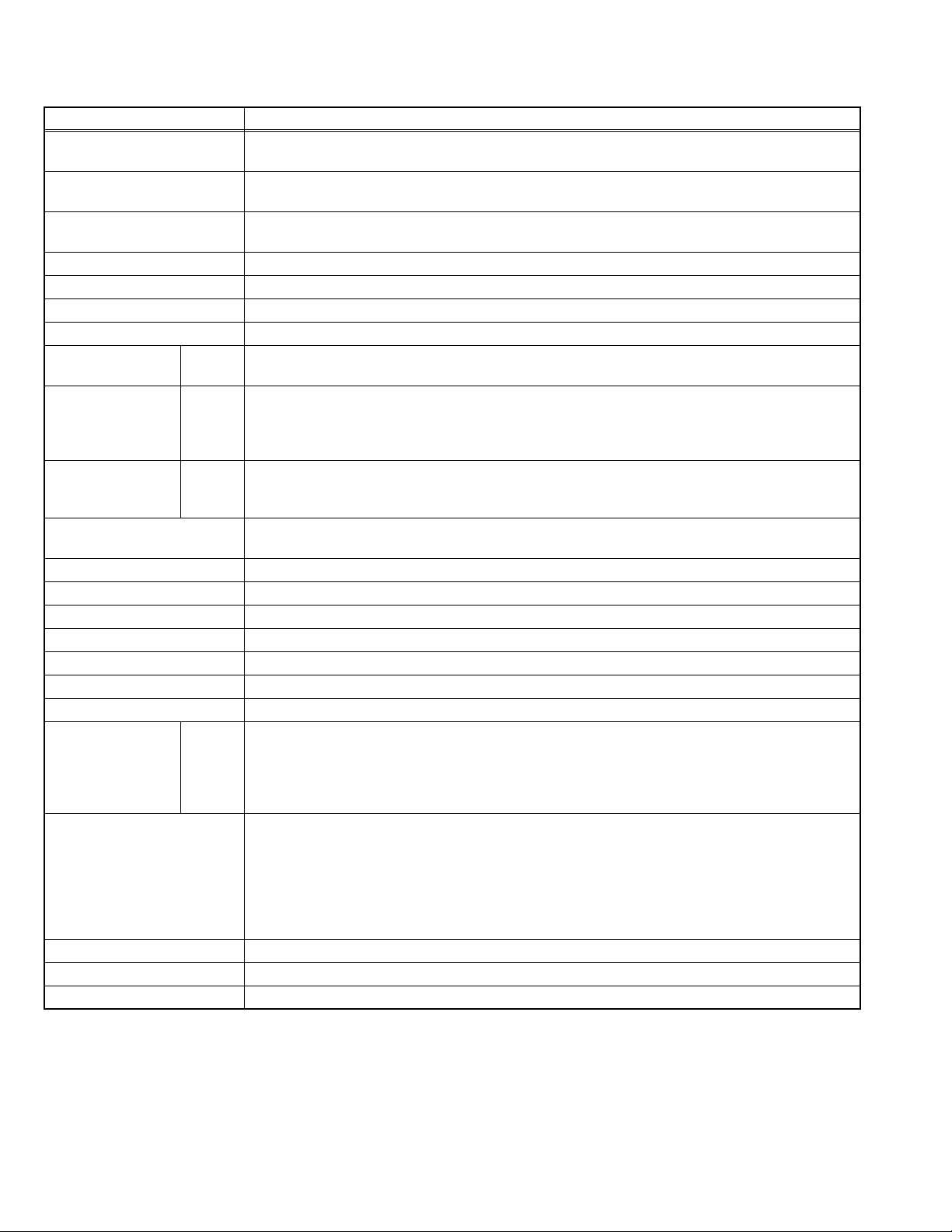
SPECIFICATION
Items Contents
Dimensions ( W × H × D ) 48.9cm × 35.3cm × 18.3cm [Included stand]
48.9cm × 30.4cm × 6.2cm [TV only]
Mass 7.5kg [Included stand]
6.0kg [TV only]
Power Input DC12V
AC220 ~ 240V 50Hz
Power Consumption 41W (Standby: 3.0W)
TV RF System CCIR (B/G, DK, I, L)
Colour System PAL / SECAM / NTSC 3.58/4.43 [EXT only]
Stereo System A2 (B/G) / NICAM (B/G, I, L)
Receiving Frequency VHF
Intermediate
Frequency
Colour Sub
Carrier Frequency
Teletext System FLOF (Fastext level 2.5), WST(World Standard system)
LCD panel 15V-inch (4 : 3)
Screen Size Diagonal : 38.1cm (H: 30.4cm × V: 22.8cm)
Display Pixels Horizontal : 1024 dots × Vertical : 768 dots (XGA)
Audio Power Output 3W + 3W(10% THD)
Speaker 3.3cm × 10.5cm × 2
Aerial terminal (VHF/UHF) F-type connector, 75Ω unbalanced, coaxial
EXT-1 (Input / Output) 21-pin Euro connector (SCART socket ) × 1
EXT-2 (Input) S-Video
PC (RGB) Input D-sub 15pin × 1
PC AUDIO input 3.5mm stereo mini jack × 1
Headphone 3.5mm stereo mini jack × 1
Remote Control Unit RM-C1861 (AA/R6 dry cell battery × 2)
SECAM
47 MHz - 470 MHz
UHF
470 MHz - 862 MHz
VIF
38.9 MHz (B/G, I, L)
SIF
33.4 MHz (5.5MHz : B/G)
32.9 MHz (6.0MHz : I)
32.4 MHz (6.5MHz : L)
PAL
4.43 MHz
4.40625 MHz / 4.25MHz
NTSC
3.58 MHz / 4.43 MHz
TOP (German system)
Mini-DIN 4 pin × 1
Y: 1V (p-p), Positive (Negative sync provided), 75 Ω
C: 0.286V (p-p) (Burst signal), 75 Ω
Video
1V (p-p), Positive (Negative sync provided), 75 Ω, RCA pin jack × 1
Audio
500mV (rms), High impedance, RCA pin jack × 2
R/G/B : 0.7V (p-p), 75Ω
HD / VD : 1V (p-p) to 5V (p-p), high impedance
< Available signal >
Horizontal : 30kHz - 57kHz
Vertical : 50Hz - 72Hz
[ Resolution : 640 pixels × 480 pixels(VGA), 800 pixels × 600 pixels(SVGA), 1024 pixels × 768 pixels(XGA) ]
Design & specifications are subject to change without notice.
1-2 (No.YA306)
Page 3
SECTION 1
PRECAUTION
1.1 SAFETY PRECAUTIONS [EXCEPT FOR UK]
(1) The design of this product contains special hardware,
many circuits and components specially for safety
purposes. For continued protection, no changes should be
made to the original design unless authorized in writing by
the manufacturer. Replacement parts must be identical to
those used in the original circuits. Service should be
performed by qualified personnel only.
(2) Alterations of the design or circuitry of the products should
not be made. Any design alterations or additions will void
the manufacturer's warranty and will further relieve the
manufacturer of responsibility for personal injury or
property damage resulting therefrom.
(3) Many electrical and mechanical parts in the products have
special safety-related characteristics. These
characteristics are often not evident from visual inspection
nor can the protection afforded by them necessarily be
obtained by using replacement components rated for
higher voltage, wattage, etc. Replacement parts which
have these special safety characteristics are identified in
the parts list of Service manual. Electrical components
having such features are identified by shading on the
schematics and by ( ) on the parts list in Service
manual. The use of a substitute replacement which does
not have the same safety characteristics as the
recommended replacement part shown in the parts list of
Service manual may cause shock, fire, or other hazards.
(4) Don't short between the LIVE side ground and
ISOLATED (NEUTRAL) side ground or EARTH side
ground when repairing.
Some model's power circuit is partly different in the GND.
The difference of the GND is shown by the LIVE : ( ) side
GND, the ISOLATED (NEUTRAL) : ( ) side GND and
EARTH : ( ) side GND.
Don't short between the LIVE side GND and ISOLATED
(NEUTRAL) side GND or EARTH side GND and never
measure the LIVE side GND and ISOLATED (NEUTRAL)
side GND or EARTH side GND at the same time with a
measuring apparatus (oscilloscope etc.). If above note will
not be kept, a fuse or any parts will be broken.
(5) When service is required, observe the original lead dress.
Extra precaution should be given to assure correct lead
dress in the high voltage circuit area. Where a short circuit
has occurred, those components that indicate evidence of
overheating should be replaced. Always use the
manufacturer's replacement components.
(6) Isolation Check (Safety for Electrical Shock Hazard)
After re-assembling the product, always perform an
isolation check on the exposed metal parts of the cabinet
(antenna terminals, video/audio input and output terminals,
Control knobs, metal cabinet, screw heads, earphone jack,
control shafts, etc.) to be sure the product is safe to operate
without danger of electrical shock.
a) Dielectric Strength Test
The isolation between the AC primary circuit and all metal
parts exposed to the user, particularly any exposed metal
part having a return path to the chassis should withstand a
voltage of 3000V AC (r.m.s.) for a period of one second. (.
. . . Withstand a voltage of 1100V AC (r.m.s.) to an
appliance rated up to 120V, and 3000V AC (r.m.s.) to an
appliance rated 200V or more, for a period of one second.)
This method of test requires a test equipment not generally
found in the service trade.
b) Leakage Current Check
Plug the AC line cord directly into the AC outlet (do not use
a line isolation transformer during this check.). Using a
"Leakage Current Tester", measure the leakage current
from each exposed metal part of the cabinet, particularly
any exposed metal part having a return path to the chassis,
to a known good earth ground (water pipe, etc.). Any
leakage current must not exceed 0.5mA AC (r.m.s.).
However, in tropical area, this must not exceed 0.2mA AC
(r.m.s.).
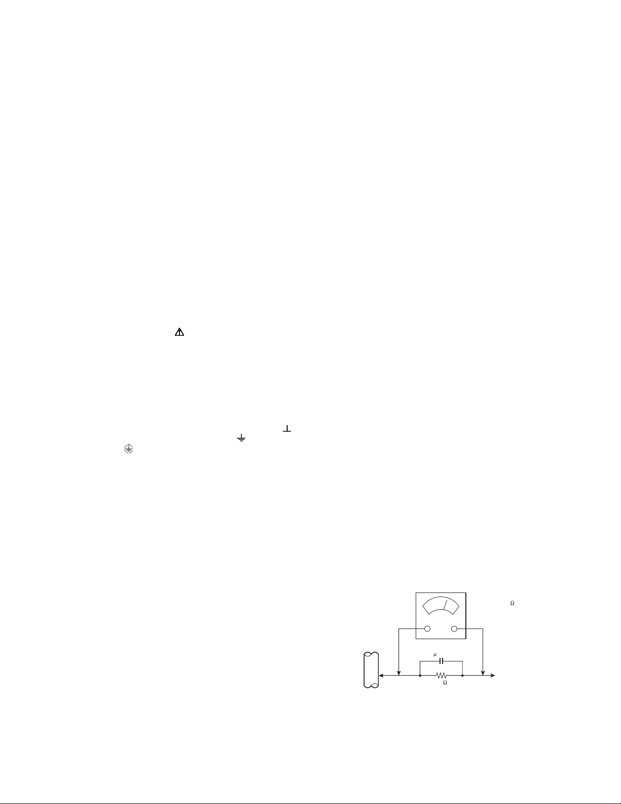
Alternate Check Method
Plug the AC line cord directly into the AC outlet (do not
use a line isolation transformer during this check.). Use
an AC voltmeter having 1000Ω per volt or more
sensitivity in the following manner. Connect a 1500Ω
10W resistor paralleled by a 0.15µF AC-type capacitor
between an exposed metal part and a known good earth
ground (water pipe, etc.). Measure the AC voltage
across the resistor with the AC voltmeter. Move the
resistor connection to each exposed metal part,
particularly any exposed metal part having a return path
to the chassis, and measure the AC voltage across the
resistor. Now, reverse the plug in the AC outlet and
repeat each measurement. Any voltage measured must
not exceed 0.75V AC (r.m.s.). This corresponds to
0.5mA AC (r.m.s.).
However, in tropical area, this must not exceed 0.3V AC
(r.m.s.). This corresponds to 0.2mA AC (r.m.s.).
AC VOLTMETER
(HAVING 1000 /V,
OR MORE SENSITIVITY)
0.15 F AC-TYPE
GOOD EARTH GROUND
1500 10W
PLACE THIS PROBE
ON EACH EXPOSED
ME TAL PAR T
(No.YA306)1-3
Page 4

1.2 SAFETY PRECAUTIONS [FOR UK]
(1) The design of this product contains special hardware and many circuits and components specially for safety purposes. For
continued protection, no changes should be made to the original design unless authorized in writing by the manufacturer.
Replacement parts must be identical to those used in the original circuits. Service should be performed by qualified personnel
only.
(2) Alterations of the design or circuitry of the product should not be made. Any design alterations or additions will void the
manufacturer's warranty and will further relieve the manufacturer of responsibility for personal injury or property damage
resulting therefrom.
(3) Many electrical and mechanical parts in the product have special safety-related characteristics. These characteristics are often
not evident from visual inspection nor can the protection afforded by them necessary be obtained by using replacement
components rated for higher voltage, wattage, etc. Replacement parts which have these special safety characteristics are
identified in the Parts List of Service Manual. Electrical components having such features are identified by shading on the
schematics and by ( ) on the Parts List in the Service Manual. The use of a substitute replacement which does not have the
same safety characteristics as the recommended replacement part shown in the Parts List of Service Manual may cause shock,
fire, or other hazards.
(4) The leads in the products are routed and dressed with ties, clamps, tubing’s, barriers and the like to be separated from live parts,
high temperature parts, moving parts and / or sharp edges for the prevention of electric shock and fire hazard. When service is
required, the original lead routing and dress should be observed, and it should be confirmed that they have been returned to
normal, after re-assembling.
WARNING
(1) The equipment has been designed and manufactured to meet international safety standards.
(2) It is the legal responsibility of the repairer to ensure that these safety standards are maintained.
(3) Repairs must be made in accordance with the relevant safety standards.
(4) It is essential that safety critical components are replaced by approved parts.
(5) If mains voltage selector is provided, check setting for local voltage.
1-4 (No.YA306)
Page 5

1.3 INSTALLATION
1.3.1 HEAT DISSIPATION
If the heat dissipation vent behind this unit is blocked, cooling
efficiency may deteriorate and temperature inside the unit will
rise. The temperature sensor that protects the unit will be
activated when internal temperature exceeds the pre-determined
level and power will be turned off automatically.Therefore,
please make sure pay attention not to block the heat dissipation
vent as well as the ventilation outlet behind the unit and ensure
that there is room for ventilation around it.
Ventilation hole
*Diagram differs from actual appearance.
1.3.2 INSTALLATION REQUIREMENTS
Ensure that the minimal distance is maintained, as specified
below, between the unit with and the surrounding walls, as well
as the floor etc.Install the unit on stable flooring or stands.Take
precautionary measures to prevent the unit from tipping in order
to protect against accidents and earthquakes.
1.3.3 NOTES ON HANDLING
(1) WHEN TAKING UNIT OUT OF A PACKING CASE
When taking the unit out of a packing case, do not grasp
the upper part of the unit. If you take the unit out while
grasping the upper part, the LCD PANEL may be damaged
because of a pressure. Instead of grasping the upper part,
put your hands on the lower backside or sides of the unit.
(2) AS FOR PRESSING OR TOUCHING A SPEAKER
Be careful not to press the opening of the speaker in the
lower part of the unit and around them since the decorative
sheet on the surface of the openings may be deformed.
100 mm
100 mm
*Diagram differs from actual appearance.
100 mm
100 mm
50 mm
(No.YA306)1-5
Page 6

1.4 HANDLING LCD PANEL
1.4.1 PRECAUTIONS FOR TRANSPORTATION
When transporting the unit, pressure exerted on the internal LCD
panel due to improper handling (such as tossing and dropping)
may cause damages even when the unit is carefully packed. To
prevent accidents from occurring during transportation, pay
careful attention before delivery, such as through explaining the
handling instructions to transporters.
Ensure that the following requirements are met during
transportation, as the LCD panel of this unit is made of glass and
therefore fragile:
(1) USE A SPECIAL PACKING CASE FOR THE LCD PANEL
When transporting the LCD panel of the unit, use a special
packing case (packing materials). A special packing case
is used when a LCD panel is supplied as a service spare
part.
(2) ATTACH PROTECTION SHEET TO THE FRONT
Since the front (display part) of the panel is vulnerable,
attach the protection sheet to the front of the LCD panel
before transportation. Protection sheet is used when a LCD
panel is supplied as a service spare part.
(3) AVOID VIBRATIONS AND IMPACTS
The unit may be broken if it is toppled sideways even when
properly packed. Continuous vibration may shift the gap of
the panel, and the unit may not be able to display images
properly. Ensure that the unit is carried by at least 2
persons and pay careful attention not to exert any vibration
or impact on it.
(4) DO NOT PLACE EQUIPMENT HORIZONTALLY
Ensure that it is placed upright and not horizontally during
transportation and storage as the LCD panel is very
vulnerable to lateral impacts and may break. During
transportation, ensure that the unit is loaded along the
traveling direction of the vehicle, and avoid stacking them
on one another. For storage, ensure that they are stacked
in 2 layers or less even when placed upright.
1.4.2 OPTICAL FILTER (ON THE FRONT OF THE LCD PANEL)
(1) Avoid placing the unit under direct sunlight over a
prolonged period of time. This may cause the optical filter
to deteriorate in quality and COLOUR.
(2) Clean the filter surface by wiping it softly and lightly with a
soft and lightly fuzz cloth (such as outing flannel).
(3) Do not use solvents such as benzene or thinner to wipe the
filter surface. This may cause the filter to deteriorate in
quality or the coating on the surface to come off. When
cleaning the filter, usually use the neutral detergent diluted
with water. When cleaning the dirty filter, use water-diluted
ethanol.
(4) Since the filter surface is fragile, do not scratch or hit it with
hard materials. Be careful enough not to touch the front
surface, especially when taking the unit out of the packing
case or during transportation.
1.4.3 PRECAUTIONS FOR REPLACEMENT OF EXTERIOR
PARTS
Take note of the following when replacing exterior parts (REAR
COVER, FRONT PANEL, etc.):
(1) Do not exert pressure on the front of the LCD panel (filter
surface). It may cause irregular COLOUR.
(2) Pay careful attention not to scratch or stain the front of the
LCD panel (filter surface) with hands.
(3) When replacing exterior parts, the front (LCD panel) should
be placed facing downward. Place a mat, etc. underneath
to avoid causing scratches to the front (filter surface).
1-6 (No.YA306)
Page 7
SECTION 2
SPECIFIC SERVICE INSTRUCTIONS
2.1 FEATURES
ZOOM
This function can change the screen size according to the
picture aspect ratio.
OFF TIMER
This function can set the TV to automatically turn off after a set
time.
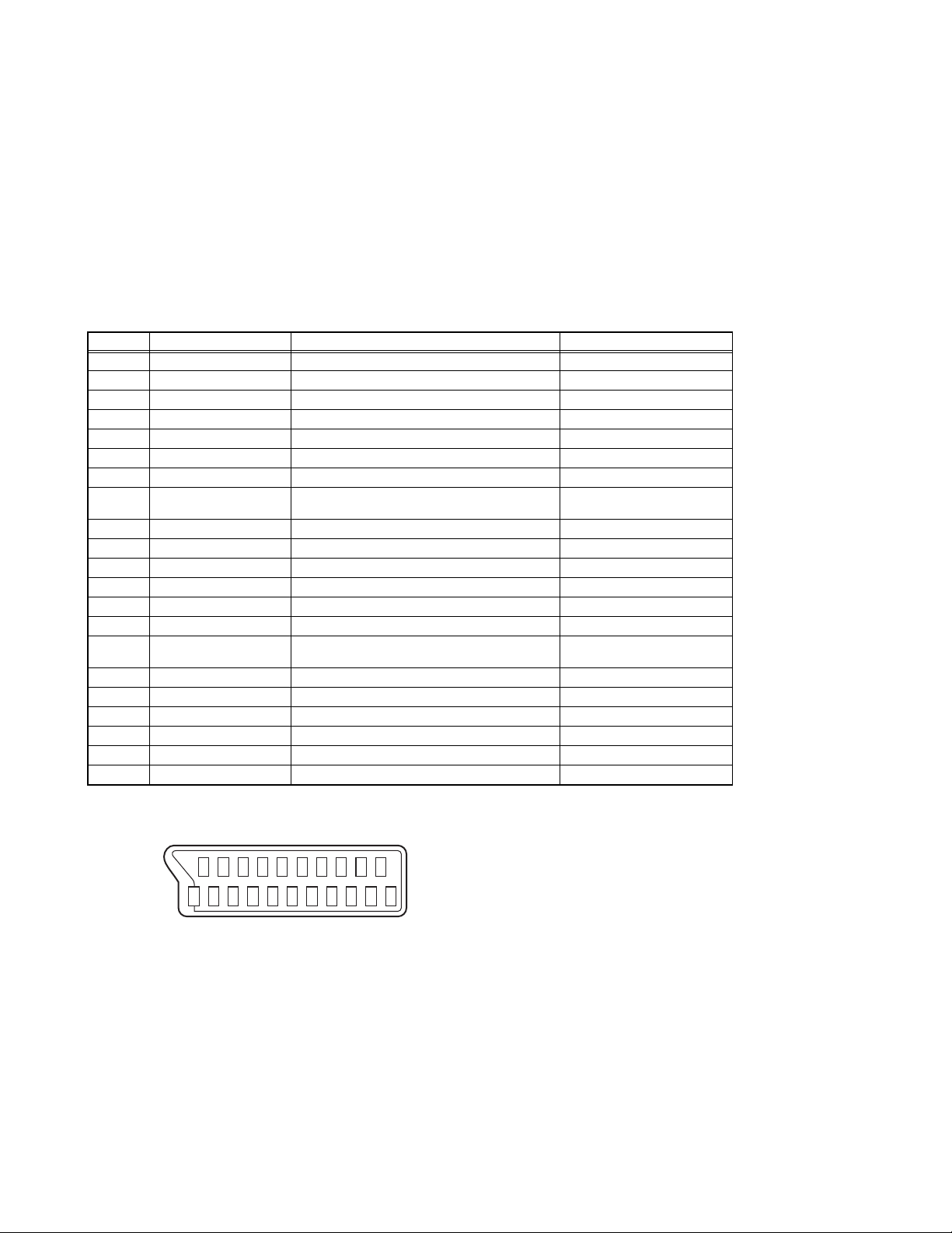
2.2 21-PIN EURO CONNECTOR (SCART) : EXT-1
Pin No. Signal designation Matching value EXT-1
1 AUDIO R output 500mV(rms) (Nominal),, Low impedance Used (TV OUT)
2 AUDIO R input 500mV(rms) (Nominal),, High impedance Used (R1)
3 AUDIO L output 500mV(rms) (Nominal),, Low impedance Used (TV OUT)
4 AUDIO GND Used
5 GND (B) Used
6 AUDIO L input 500mV(rms) (Nominal),, High impedance Used (L1)
7 B input 700mV
8 FUNCTION SW
(SLOW SW)
9 GND (G) Used
10 SCL / T-V LINK Not used
11 G input 700mV
12 SDA Not used
13 GND (R) Used
14 GND (YS) Used
15 R / C input R : 700mV
16 Ys input (FAST SW) Low : 0V-0.4V, High : 1V-3V, 75Ω Used
17 GND (VIDEO output) Used
18 GND (VIDEO input) Used
19 VIDEO output 1V
20 VIDEO / Y input 1V
21 COMMON GND Used
Low : 0V-3V
High : 8V-12V, High impedance
C : 300mV
(P-P)
(P-P)
, 75Ω Used
(B-W)
, 75Ω Used
(B-W)
, 75Ω
(B-W)
, 75Ω
(P-P)
(Negative sync), 75Ω Used (TV OUT)
(Negative sync), 75Ω Used
(P-P= Peak to Peak, B-W= Blanking to white peak)
[Pin assignment]
20 18 16 14 12 10 8 6 4 2
COLOUR SYSTEM
If the picture is not clear or no colour appears, change the
current colour system to another colour system.
Used
Used (R)
21 19 17 15 13 11 9 7 5 3 1
(No.YA306)1-7
Page 8
2.3 TECHNICAL INFORMATION
2.3.1 LCD PANEL
This unit uses the flat type panel LCD (Liquid Crystal Display) panel that occupies as little space as possible, instead of the
conventional CRT (Cathode Ray Tube), as a display unit.
Since the unit has the two polarizing filter that are at right angles to each other, the unit adopts "normally black" mode, where light
does not pass through the polarizing filter and the screen is black when no voltage is applied to the liquid crystals.
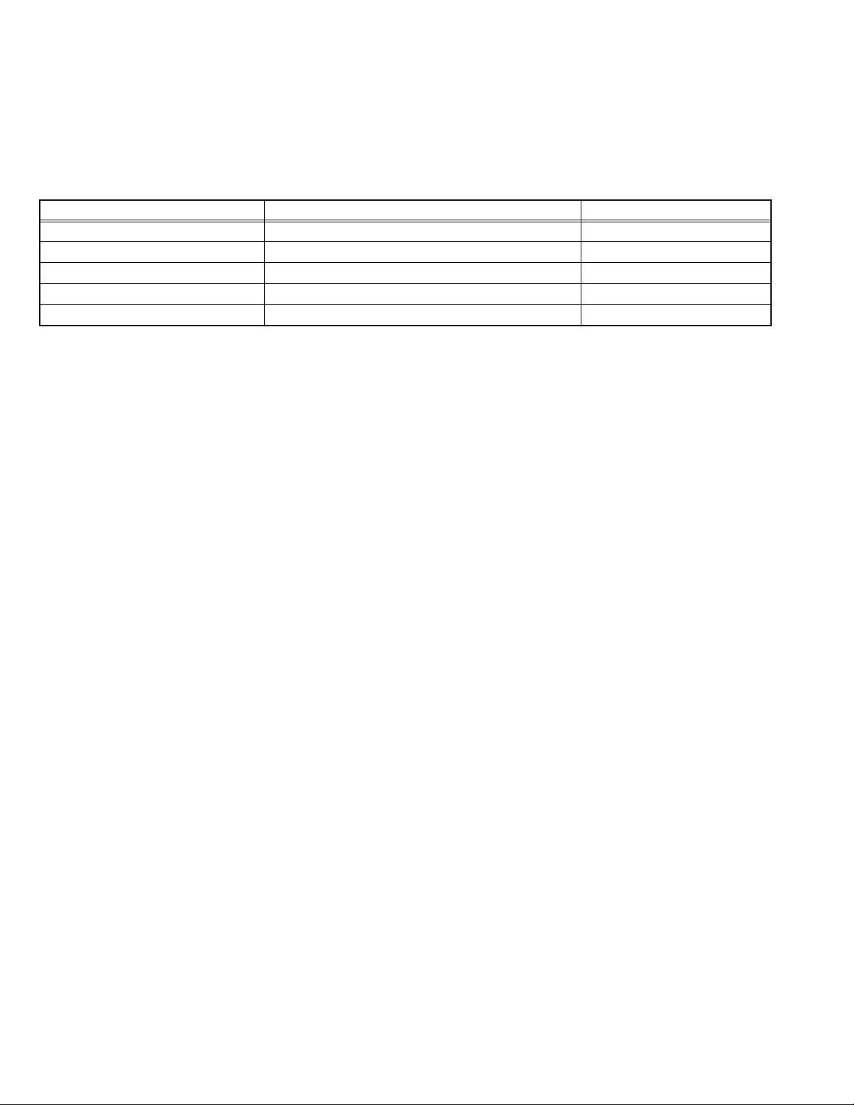
2.3.1.1 SPECIFICATIONS
The following table shows the specifications of this unit.
Item Specifications Remarks
Displayed colour 16777216 colours 256 colours for R, G, and B
Brightness 450cd/m
2
Contrast ratio 400: 1
Response time 25ms
View angle Horizontally: 176°, Vertically: 176°
2.3.1.2 PIXEL FAULT
There are three pixel faults - bright fault , dark fault and flicker fault - that are respectively defined as follows.
BRIGHT FAULT
In this pixel fault, a cell that should not light originally is lighting on and off.
For checking this pixel fault, input ALL BLACK SCREEN and find out the cell that is lighting on and off.
DARK FAULT
In this pixel fault, a cell that should light originally is not lighting or lighting with the brightness twice as brighter as originally lighting.
For checking this pixel fault, input 100% of each R/G/B colour and find out the cell that is not lighting.
FLICKER FAULT
In the pixel fault, a cell that should light originally or not light originally is flashing on and off.
For checking this pixel fault, input ALL BLACK SCREEN signal or 100% of each RGB colour and find out the cell that is flashing on
and off.
1-8 (No.YA306)
Page 9
2.4 BASIC OPERATION OF UOCIII SERVICE MODE
2.4.1 HOW TO ENTER THE UOCIII SERVICE MODE
(1) Press [MENU] key.
(2) Press the [4], [7], [2] and [5] key, and UOCIII SERVICE
MODE screen will be displayed.
UOCIII SERVICE MODE SCREEN
GTV 3.2.1
000
EurAsia TVSub
00000000 00111100
01000000 01100100
11000101 01100100
00000000 01100100
2.4.2 HOW TO EXIT THE UOCIII SERVICE MODE
Press [MENU] key to exit the UOCIII SERVICE MODE.
2.4.3 CHANGE AND MEMORY OF SETTING VALUE
SELECTION OF SETTING MENU & ITEM
• [P +/-] key.
CHANGE OF SETTING VALUE(DATA)
• [Volume +/-] key.
MEMORY OF SETTING VALUE(DATA)
The setting value will be stored automatically when release the
REMOTE CONTROL UNIT keys.
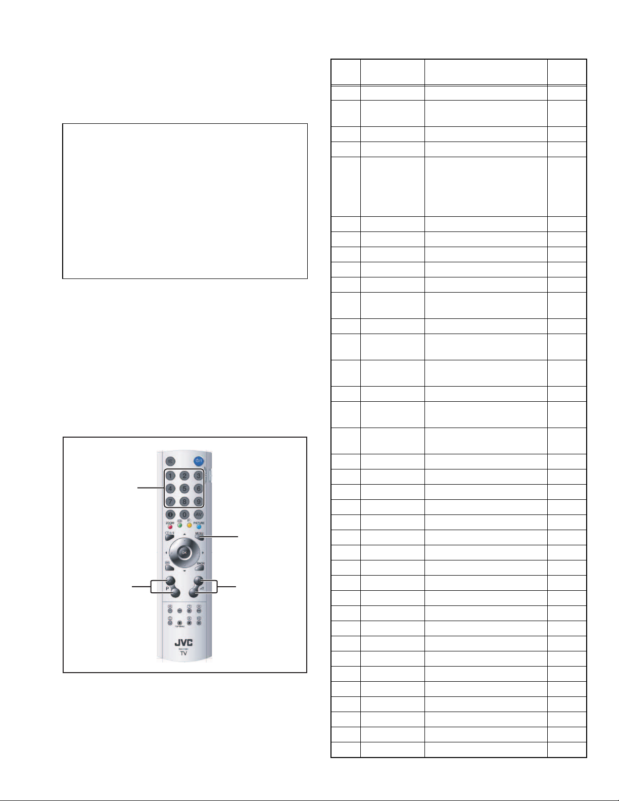
2.4.4 UOCIII SERVICE MODE SELECT KEY LOCATION
Number key
[P +/-]
05.01
[MENU]
[Volume +/-]
2.4.5 UOCIII SERVICE MODE SETTING ITEMS
Item
Setting items Function
No.
EurAsia TVSub
000
001 Init TV Sets the UOC default values
and turns the tv to Stdby
002 ISP Mode Sets the TV into ISP state. 0
003 DCXO DCXO crystal alignment 70
004 DCXO Auto Automatic DCXO frequency
alignment. When it is set to 1;
UOC automaticaly calculates
DCXO values and writes it to
item number 3.
005 Rotation 31
006 Hor. Shift 32
007 HBL 0
008 WBF 4
009 WBR 8
010 WSS WSS (Wide Screen Sigan-
ling) enable
011 Gld-SCART 1
012 Col Fe Color Saturation adjustment
for RF input
013 Col AV1 Color Saturation adjustment
for Scart CVBS input
014 Col AV1S 32
015 Col AV2 Color Saturation adjustment
for AV CVBS input
016 Col AV2S Color Saturation adjustment
for for SVHS S-video input
017 BLOR 32
018 BLOG 32
019 RGB 14
020 YSECAM
021 YNTSC
022 YPAL "Y delay" setting. (PAL) (0-15) 8
023 YAV1
024 YAV2 "Y delay" setting. (FAV) (0-15) 4
025 YSVHS1 "Y delay" setting. (0-15) 4
026 YSVHS2
027 ACL 0
028 MUS 0
029 PWL 8
030 CB 0
031 BPS 0
032 FCO 0
PeakFreqPAL443
033
PeakFreqPALM
034
PeakFreqPALN
035
PeakFreqNTSC443
036
"Y delay" setting. (SECAM) (0-15)
"Y delay" setting. (NTSC) (0-15)
"Y delay" setting. (SCART) (0-15)
"Y delay" setting. (S-Video) (0-15)
Setting
value
05.01
0
0
1
32
32
32
32
8
8
4
4
1
1
1
1
(No.YA306)1-9
Page 10
Item
Setting items Function
No.
PeakFreqNTSCM
037
PeakFreqSECAM
038
039 PeakFreqAV 1
040 Blackstretch 1
041 Bluestretch 0
042 Whitestretch 0
043 Transfer Rato 1
PeakRatioOvShot
044
045 Tint NTSC 31
046 OSO 0
047 FSL 0
048 HP2 0
049 SoftClipLevel 0
OP AUDIO CONFIG
050
051 OP BILING 1
052 OP HP 1
053 OP EQUAL 1
054 OP DOLBY 0
055 OP TRUSUR 0
056 OP DUB DBE 0
057 OP BBE 0
058 AVL-LEV AVL Level setting 1
059 AVL-WGT AVL Weight setting 1
060 AVL-MOD AVL Response Time setting 3
061 AVLE AVL enable/disable 1
062 LOUD-NA 5
063 LOUD-CH 1
064 BBE-CONT 7
065 BBE-PROC 7
066 OP CLIP 0
067 DEC-LEV
068 MONO-LEV FM Mono Prescale setting 23
069 NIC-LEV Nicam Str. Prescale setting 17
070 ADC-AM-L AM Mono Prescale setting 21
071 ADC-AV-L Scart/Line in Prescale setting 18
072 BGSCAL DEC 0
BGSCAL MONO
073
074 BGSCAL NIC 0
075 BGSCAL SAP 0
076 MSCAL DEC 0
077 MSCAL
MONO
078 MSCAL NIC 0
079 MSCAL SAP 0
080 LSCAL DEC 0
081 LSCAL MONO 0
FM German Str. Prescale setting
Setting
value
1
1
2
2
23
0
0
Item
Setting items Function
No.
082 LSCAL NIC 0
083 LSCAL SAP 0
084 E2D 0
085 FFI 0
086 CMUTE 1
087 PA-BA-VO 31
088 PA-TR-VO 15
089 PA-LM-VO 1
090 PA-ST-VO 5
091 PA-LO-VO 0
092 PA-B1-VO 21
093 PA-B2-VO 50
094 PA-B3-VO 55
095 PA-B4-VO 45
096 PA-B5-VO 34
097 PA-BA-MU 34
098 PA-TR-MU 39
099 PA-LM-MU 1
100 PA-ST-MU 5
101 PA-LO-MU 1
102 PA-B1-MU 52
103 PA-B2-MU 47
104 PA-B3-MU 29
105 PA-B4-MU 29
106 PA-B5-MU 45
107 PA-BA-TH 36
108 PA-TR-TH 34
109 PA-LM-TH 1
110 PA-ST-TH 5
111 PA-LO-TH 0
112 PA-B1-TH 47
113 PA-B2-TH 45
114 PA-B3-TH 42
115 PA-B4-TH 45
116 PA-B5-TH 42
117 AGC Speed AGC Speed setting 1
AGC Take over
118
119 OIF IF Demodulator Offset 32
120 IF IF Frequency 2
121 SVO 0
122 GD 1
123 BPB 0
124 BPB2 0
125 RGB-IN 1
126 DVD1-IN 0
AGC setting 27
Setting
value
1-10 (No.YA306)
Page 11
Item
Setting items Function
No.
127 AV2-IN 1
128 DVD2-IN 0
129 AV1S-IN 0
130 AV1D-IN 0
131 AV2S-IN 1
132 CBVS-OUT 1
133 INCL-AV 0
134 TXT-ON 1
135 TXT-SPLIT 1
136 TXT-H-POS 11
137 TIM-REM 1
138 TIM-SLP 1
139 TIM-SW 1
140 TIM-OFF 1
141 TIM-SKP 1
142 TIM-RT 1
143 FM Radio 1
144 PWR-SAVING 1
145 PWR-PERF 3
146 PWR-REST 0
147 PWR-ONKEY 1
148 Factory Mode 0
149 CombFil Combfilter enable/disable 1
BlueBlackNoMute
150
151 ATS 1
152 EVG 0
153 DFL 0
154 XDT 0
155 AKB 1
156 OSVE 0
157 CL 10
158 LCD-BRT UOC Brightness 36
159 LCD-CON UOC Contrast 32
160 LCD-CON-FE RF Frontend Contrast adjust. 30
LCD-CON-AV1
161
LCD-CON-AV1S
162
LCD-CON-AV2
163
LCD-CON-AV2S
164
165 RBL 0
166 EGL 0
167 LPG 1
168 PGR UOC Red Contrast 32
169 PGG-CVBS
170 PGG-RGB
171 PGB UOC Blue Contrast 32
Scart CVBS Contrast adjust. 32
AV CVBS Contrast adjust. 32
S-Video input Contrast adjust. 32
UOC Green Contrast for CVBS input
UOC Green Contrast for RGB input
Setting
value
32
32
34
2.5 BASIC OPERATION OF PW SERVICE MODE
2.5.1 HOW TO ENTER THE PW SERVICE MODE
(1) Press [MENU] key.
(2) Press the [4], [7], [2] and [6] key, and PW SERVICE
MODE screen will be displayed.
2.5.2 HOW TO EXIT THE PW SERVICE MODE
Press [MENU] key to exit the PW SERVICE MODE.
2.5.3 CHANGE AND MEMORY OF SETTING VALUE
SELECTION OF SETTING MENU & ITEM
• [FUNCTION /] and [FUNCTION /] key.
CHANGE OF SETTING VALUE(DATA)
• [FUNCTION /] key.
MEMORY OF SETTING VALUE(DATA)
The setting value will be stored automatically when release the
REMOTE CONTROL UNIT keys.
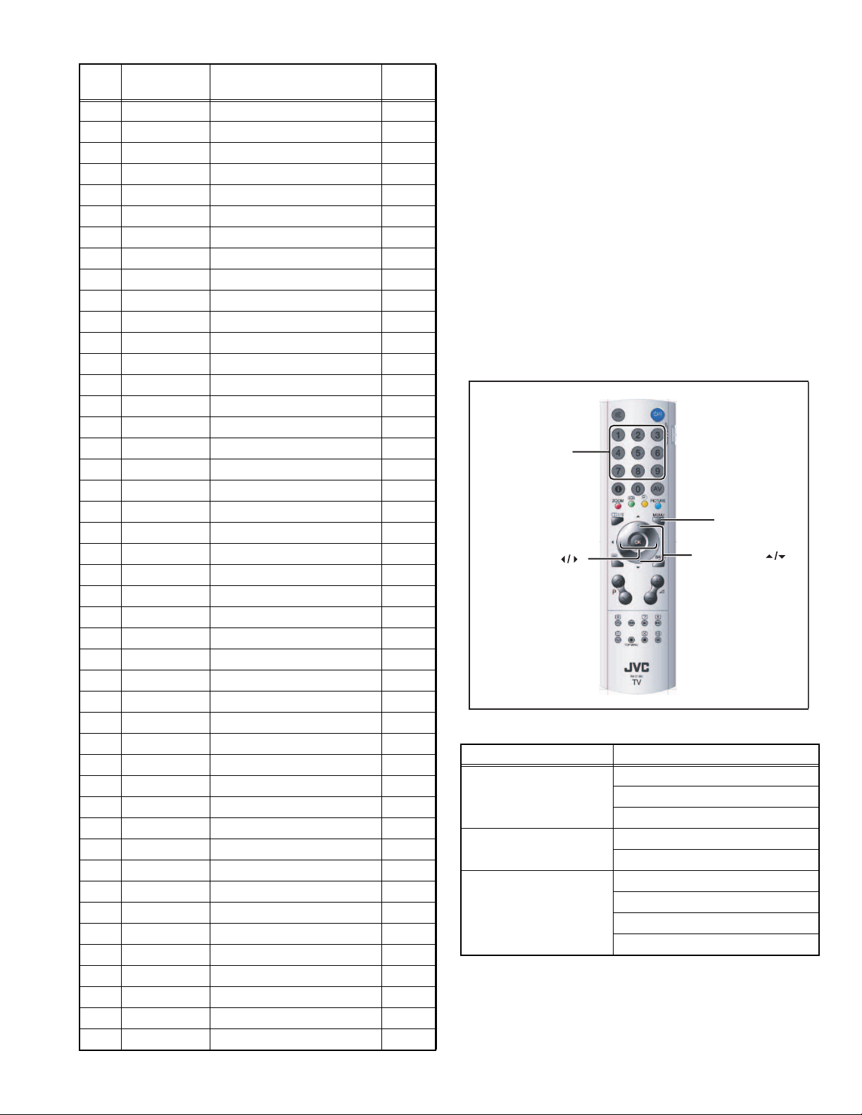
2.5.4 PW SERVICE MODE SELECT KEY LOCATION
Number key
[MENU]
[FUNCTION ]
0
2.5.5 PW SERVICE MODE SETTING ITEMS
Setting menu Setting items
Submenu 1 UOC Hposition
ADC_Calibration
UOC_Calibration
Submenu 2 Init NVM
Initial APS
Submenu 3 Country
Language
Menu Background
Remote Control
[FUNCTION ]
(No.YA306)1-11
Page 12

SECTION 3
DISASSEMBLY
3.1 DISASSEMBLY PROCEDURE
NOTE:
• Make sure that the power cord is disconnected from the outlet.
• Pay special attention not to break or damage the parts.
• When removing each board, remove the connectors as required.
• Taking notes of the connecting points (connector numbers) makes service procedure manageable.
• Make sure that there is no bent or stain on the connectors before inserting, and firmly insert the connectors.
3.1.1 REMOVING THE FOOT ASSEMBLY
(1) Remove the HINGE COVER.
(2) Remove the 4 screws [A], then remove the FOOT
ASSEMBLY.
3.1.2 REMOVING THE BACK COVER
• Remove the HINGE COVER & the FOOT ASSEMBLY.
(1) Remove the SOCKET DOOR.
(2) Remove the 7 screws [B].
(3) Remove the BACK COVER toward you.
3.1.3 REMOVING THE AV JACK BRACKET
• Remove the HINGE COVER & the FOOT ASSEMBLY.
• Remove the BACK COVER.
(1) Remove the 2 screws [C].
(2) Remove the AV JACK BRACKET.
3.1.4 REMOVING THE AV JACK PWB
• Remove the HINGE COVER & the FOOT ASSEMBLY.
• Remove the BACK COVER.
• Remove the AV JACK BRACKET.
(1) Remove the 2 screws [D].
(2) Remove the AV JACK PWB.
3.1.5 REMOVING THE FRONT CONTROL PWB
• Remove the HINGE COVER & the FOOT ASSEMBLY.
• Remove the BACK COVER.
(1) Remove the 2 screws [E].
(2) Remove the FRONT CONTROL PWB with FUNCTION
BUTTON.
(3) Remove the FRONT CONTROL PWB from FUNCTION
BUTTON.
3.1.6 REMOVING THE MAIN PWB
• Remove the HINGE COVER & the FOOT ASSEMBLY.
• Remove the BACK COVER.
(1) Remove the 7 screws [F].
(2) Remove the MAIN PWB.
3.1.9 REMOVING THE MAIN FRAME
• Remove the HINGE COVER & the FOOT ASSEMBLY.
• Remove the BACK COVER.
• Remove the SCART BRACKET.
(1) Remove the 4 screws [J].
(2) Remove the MAIN FRAME from the FRONT PANEL.
3.1.10 REMOVING THE LCD PANEL UNIT
• Remove the HINGE COVER & the FOOT ASSEMBLY.
• Remove the BACK COVER.
• Remove the SCRAT BRACKET.
• Remove the MAIN FRAME.
(1) Remove the 4 screws [K].
(2) Sightly raise the both sides of the LCD PANEL UNIT by
hand from the MAIN FRAME.
NOTE :
• Pay special attention not to break or damage on the LCD
PANEL face or frame.
• The LCD PANEL UNIT is fixed to the FRONT COVER (at the
back side) by using double-side adhesive tapes. To remove
the LCD PANEL UNIT, remove the adhesive tape on the
FRONT PANELslowly.
3.1.11 REMOVING THE SPEAKERS
• Remove the HINGE COVER & the FOOT ASSEMBLY.
• Remove the BACK COVER.
(1) Remove the 2 screws [L].
(2) Remove the SPEAKER from the FRONT PANEL.
(3) Follow the same when removing the other hand speaker.
3.1.12 REMOVING THE LED PWB
• Remove the HINGE COVER & the FOOT ASSEMBLY.
• Remove the BACK COVER.
(1) Remove the 2 screws [M].
(2) Remove the LED PWB from the FRONT PANEL.
3.1.7 REMOVING THE INVERTER UNIT
• Remove the HINGE COVER & the FOOT ASSEMBLY.
• Remove the BACK COVER.
(1) Remove the 2 screws [G].
(2) Remove the INVERTER UNIT.
3.1.8 REMOVING THE SCART BRACKET
• Remove the HINGE COVER & the FOOT ASSEMBLY.
• Remove the BACK COVER.
(1) Remove the 2 screws [H].
(2) Remove the SCART BRACKET.
1-12 (No.YA306)
Page 13
G
INVERTER UNIT
J
SIDE AV
DOOR
MAIN PWB
SCART
BRACKET
B
F
K
LCD PANEL
UNIT
H
K
MAIN FRAME
BACK
COVER
SOCKET
DOOR
HINGE COVER
AV JACK
PWB
AV JACK
BRACKET
LED PWB
C
D
HANG
METAL
M
L
A
E
SPEAKER
(X2)
FRONT CONTROL
PWB
FUNCTION BUTTON
METAL HINGE
BRACKET
FRONT PANEL
FOOT SUPPORT
FOOT ASSEMBLY
(No.YA306)1-13
Page 14

3.2 MEMORY IC REPLACEMENT
• This model uses the memory IC.
• This memory IC stores data for proper operation of the video and drive circuits.
• When replacing, be sure to use an IC containing this (initial value) data.
3.2.1 SETTINGS OF FACTORY SHIPMENT
3.2.1.1 BUTTON OPERATION 3.2.1.2 REMOTE CONTROL DIRECT OPERATION
Setting item Setting position
POWER Off
TV/AV TV
3.2.1.3 REMOTE CONTROL MENU OPERATION
(1) PICTURE
Setting item Setting position
MODE Bright
Contrast 36 Step
Bright-1 26 Step
Sharpness 11 Step
Colour 39 Step
Bright-2 Med.
Colour Temp. Cool
(2) SOUND
Setting item Setting position
Volume 10 Step
Bass 16 Step
Treble 15 Step
Balance 16 Step
Hyper Sound Off
Setting item Setting position
ZOOM AUTO
(3) FEATURE
Setting item Setting position
Sleep Timer Off
Child Lock Off
Language English
Blue Back Off
(4) INSTALLATION
Setting item Setting position
Colour System Auto
VCR Off
1-14 (No.YA306)
Page 15

3.3 REPLACEMENT OF CHIP COMPONENT
3.3.1 CAUTIONS
(1) Avoid heating for more than 3 seconds.
(2) Do not rub the electrodes and the resist parts of the pattern.
(3) When removing a chip part, melt the solder adequately.
(4) Do not reuse a chip part after removing it.
3.3.2 SOLDERING IRON
(1) Use a high insulation soldering iron with a thin pointed end of it.
(2) A 30w soldering iron is recommended for easily removing parts.
3.3.3 REPLACEMENT STEPS
1. How to remove Chip parts
2. How to install Chip parts
[Resistors, capacitors, etc.]
(1) As shown in the figure, push the part with tweezers and
alternately melt the solder at each end.
(2) Shift with the tweezers and remove the chip part.
[Transistors, diodes, variable resistors, etc.]
(1) Apply extra solder to each lead.
SOLDER
SOLDER
[Resistors, capacitors, etc.]
(1) Apply solder to the pattern as indicated in the figure.
(2) Grasp the chip part with tweezers and place it on the
solder. Then heat and melt the solder at both ends of the
chip part.
[Transistors, diodes, variable resistors, etc.]
(1) Apply solder to the pattern as indicated in the figure.
(2) Grasp the chip part with tweezers and place it on the
solder.
(3) First solder lead A as indicated in the figure.
(2) As shown in the figure, push the part with tweezers and
alternately melt the solder at each lead. Shift and remove
the chip part.
NOTE :
After removing the part, remove remaining solder from the
pattern.
A
B
C
(4) Then solder leads B and C.
A
B
C
(No.YA306)1-15
Page 16

SECTION 4
ADJUSTMENT
This service manual does not describe ADJUSTMENT.
SECTION 5
TROUBLESHOOTING
This service manual does not describe TROUBLESHOOTING.
1-16 (No.YA306)
Page 17

Victor Company of Japan, Limited
AV & MULTIMEDIA COMPANY DISPLAY CATEGORY 12, 3-chome, Moriya-cho, Kanagawa-ku, Yokohama-city, Kanagawa-prefecture, 221-8528, Japan
(No.YA306)
Printed in Japan
VPT
Page 18

SCHEMATIC DIAGRAMS
WIDE LCD PANEL TELEVISION
YA306200510
LT-15B60SJ,
LT-15B60SW
CD-ROM No.SML200510
COPYRIGHT © 2005 Victor Company of Japan, Limited
No.YA306
2005/10
Page 19

LT-15B60SJ, LT-15B60SW
STANDARD CIRCUIT DIAGRAM
NOTE ON USING CIRCUIT DIAGRAMS
1.SAFETY
The components identified by the symbol and shading are
critical for safety. For continued safety replace safety ciritical
components only with manufactures recommended parts.
2.SPECIFIED VOLTAGE AND WAVEFORM VALUES
The voltage and waveform values have been measured under the
following conditions.
(1)Input signal : Colour bar signal
(2)Setting positions of
each knob/button and
variable resistor
(3)Internal resistance of tester
(4)Oscilloscope sweeping time
(5)Voltage values
Since the voltage values of signal circuit vary to some extent
according to adjustments, use them as reference values.
: Original setting position
when shipped
: DC 20kΩ/V
: H
: V
: Othters
: All DC voltage values
20µs / div
5ms / div
Sweeping time is
specified
3.INDICATION OF PARTS SYMBOL [EXAMPLE]
In the PW board
: R209
R209
Type
No indication
MM
PP
MPP
MF
TF
BP
TAN
(3)Coils
No unit
Others
(4)Power Supply
Respective voltage values are indicated
(5)Test point
: Test point
(6)Connecting method
: Ceramic capacitor
: Metalized mylar capacitor
: Polypropylene capacitor
: Metalized polypropylene capacitor
: Metalized film capacitor
: Thin film capacitor
: Bipolar electrolytic capacitor
: Tantalum capacitor
: [µH]
: As specified
: B1
: 9V
: Connector
: Receptacle
: Only test point display
: Wrapping or soldering
: B2 (12V
: 5V
)
4.INDICATIONS ON THE CIRCUIT DIAGRAM
(1)Resistors
Resistance value
No unit : [Ω]
K
M
Rated allowable power
No indication : 1/16 [W]
Others : As specified
Type
No indication
OMR
MFR
MPR
UNFR
FR
Composition resistor 1/2 [W] is specified as 1/2S or Comp.
(2)Capacitors
Capacitance value
1 or higher : [pF]
less than 1
Withstand voltage
No indication : DC50[V]
Others : DC withstand voltage [V]
AC indicated
Electrolytic Capacitors
47/50[Example]: Capacitance value [µF]/withstand voltage[V]
: [kΩ]
: [MΩ]
: Carbon resistor
: Oxide metal film resistor
: Metal film resistor
: Metal plate resistor
: Uninflammable resistor
: Fusible resistor
: [µF]
: AC withstand voltage [V]
(7)Ground symbol
: LIVE side ground
: ISOLATED(NEUTRAL) side ground
: EARTH ground
: DIGITAL ground
5.NOTE FOR REPAIRING SERVICE
This model's power circuit is partly different in the GND. The
difference of the GND is shown by the LIVE : ( ) side GND and the
ISOLATED(NEUTRAL) : ( ) side GND. Therefore, care must be
taken for the following points.
(1)Do not touch the LIVE side GND or the LIVE side GND and the
ISOLATED(NEUTRAL) side GND simultaneously. if the above
caution is not respected, an electric shock may be caused.
Therefore, make sure that the power cord is surely removed from
the receptacle when, for example, the chassis is pulled out.
(2)Do not short between the LIVE side GND and ISOLATED(NEUTRAL
side GND or never measure with a measuring apparatus measure
with a measuring apparatus ( oscilloscope, etc.) the LIVE side GND
and ISOLATED(NEUTRAL) side GND at the same time.
If the above precaution is not respected, a fuse or any parts will be broken.
Since the circuit diagram is a standard one, the circuit and
circuit constants may be subject to change for improvement
without any notice.
NOTE
Due improvement in performance, some part numbers show
in the circuit diagram may not agree with those indicated in
the part list.
When ordering parts, please use the numbers that appear
in the Parts List.
)
(No.YA306)2-1
Page 20

CONTENTS
SEMICONDUCTOR SHAPES ......................................................................2-2
BLOCK DIAGRAM ........................................................................................2-3
CIRCUIT DIAGRAMS
MAIN PWB CIRCUIT DIAGRAM ................................................................................................................ 2-5
AV JACK PWB CIRCUIT DIAGRAM ......................................................................................................... 2-15
FRONT CONTROL PWB CIRCUIT DIAGRAM .......................................................................................... 2-16
LED PWB CIRCUIT DIAGRAM ................................................................................................................. 2-16
PATTERN DIAGRAMS
MAIN PWB PATTERN .............................................................................................................................. 2-17
AV JACK PWB PATTERN ........................................................................................................................ 2-21
FRONT CONTROL PWB PATTERN ......................................................................................................... 2-21
LED PWB PATTERN ................................................................................................................................ 2-22
USING P.W. BOARD
P.W.B ASS’Y name
MAIN P.W. BOARD
FRONT CONTROL P.W. BOARD
AV JACK P.W. BOARD
LED P.W. BOARD
LT-15B60SJ LT-15B60SW
VE-20215170
VE-20214331
VE-20214317
VE-20214319
SEMICONDUCTOR SHAPES
TRANSISTOR
BOTTOM VIEW FRONT VIEW TOP VIEW
CHIP TR
E
C
B
ECB
IC
BOTTOM VIEW FRONT VIEW TOP VIEW
OUT
E
IN
IN OUTE
B
(G)E(S)C(D)
1 N
ECB
ECB
1
1 N
C
BE
N
CHIP IC
2-2(No.YA306)
TOP VIEW
1
N
1
N
Page 21

BLOCK DIAGRAM
RF in
S-Video in
CVBS in
Scart
[R,G,B]IN
MACROVISION
CVBS
PC in
FBLIN
YCbCr
Y HD_[HS,VS]
SYNC
SEPARATOR
EL1883
PC_[HS,VS]
V[R,G,B]IN
TV_HS
TV_VS
SANDC
SAW
74HC14
CTI/
LTI
BLOCK
MACROVISION
[R,G,B]OUT
[YUV,VGA]_SW
A[H,V]SYNC
RGB
VFIN (24,25)
Y4(51)
C4(52)
CVBS3/Y3(58)
AUDIOIN5L(34)
AUDIOIN5R(35)
C2(59)
CVBS2/Y2(55)
IFVO(43)
AUDIO U TSL(36)
AUDIOUTSR(37)
VDRA,HOUT(23,67)
FBLIN
R,G,B(78,79,80)
[Y,U,V]OUT(74,75,76)
YUV(72,71,70)
[R,G,B]OUT(85,86,87)
Comunication
Signals:
I2C and Handhake
PORTD[5,6](58,57)
[H,V]SYNC(65,64)
[R,G,B]AIN(37,43,50)
PORTD7(56)
UOCIII
AUDIOIN3L(56)
AUDIOIN3R(57)
AUDOUTHP[L,R](62,63)
AUDOUTLS[L,R](60,61)
I2SDO2(104)
I2SCLK(103)
I2SWS(102)
SDA_U, SCL_U
PW1306
HP DRIVER
TDA1308
AUDIO
AMPLIFIER
2xTDA7056
DAC
CS4335
EEPROM
Audio in
Audio
line out
D[R,G,B]E[0-7], PORTA7(201)
DHS,DVS,DEN,DCLK D[R,G,B]O[0-7]
LVDS
DS90C385
PANEL
Buffer
(No.YA306)2-3
Page 22

2-4(No.YA306)
Page 23

CIRCUIT DIAGRAMS
MAIN PWB CIRCUIT DIAGRAM (1/5)
MAIN PWB ASS'Y(1/5)
VE-20215170
(No.YA306)2-5 2-6(No.YA306)
17mb18-4_0527_1/5_0.0
Page 24

MAIN PWB CIRCUIT DIAGRAM (2/5)
MAIN PWB ASS'Y(2/5)
VE-20215170
17mb18-4_0527_2/5_0.0
2-8(No.YA306)(No.YA306)2-7
Page 25

MAIN PWB CIRCUIT DIAGRAM (3/5)
(No.YA306)2-9 2-10(No.YA306)
MAIN PWB ASS'Y(3/5)
VE-20215170
17mb18-4_0527_3/5_0.0
Page 26

MAIN PWB CIRCUIT DIAGRAM (4/5)
MAIN PWB ASS'Y(4/5)
VE-20215170
17mb18-4_0527_4/5_0.0
2-12(No.YA306)(No.YA306)2-11
Page 27

MAIN PWB CIRCUIT DIAGRAM (5/5)
!
MAIN PWB ASS'Y(5/5)
VE-20215170
!
(No.YA306)2-13 2-14(No.YA306)
17mb18-4_0527_5/5_0.0
Page 28

AV JACK PWB CIRCUIT DIAGRAM
FRONT CONTROL PWB CIRCUIT DIAGRAM
FRONT CONTROL PWB ASS'Y
VE-20214331
LED PWB CIRCUIT DIAGRAM
LED PWB ASS'Y
VE-20214319
AV JACK PWB ASS'Y
VE-20214317
2-16(No.YA306)(No.YA306)2-15
Page 29

PATTERN DIAGRAMS
MAIN PWB PATTERN [SOLDER SIDE]
TOP
(No.YA306)2-17 2-18(No.YA306)
Page 30

MAIN PWB PATTERN [PARTS SIDE]
TOP
2-20(No.YA306)(No.YA306)2-19
Page 31

TOP
OP
AV JACK PWB PATTERN [SOLDER SIDE]
AV JACK PWB PATTERN [PARTS SIDE]
T
FRONT CONTEROL PWB PATTERN [SOLDER SIDE]
FRONT CONTEROL PWB PATTERN [PARTS SIDE]
FRONT
FRONT
(No.YA306)2-21
Page 32

TOP
TOP
LED PWB PATTERN [SOLDER SIDE]
LED PWB PATTERN [PARTS SIDE]
2-22(No.YA306)
Page 33

Victor Company of Japan, Limited
AV & MULTIMEDIA COMPANY DISPLAY CATEGORY 12, 3-chome, Moriya-cho, Kanagawa-ku, Yokohama-city, Kanagawa-prefecture, 221-8528, Japan
(No.YA306)
Printed in Japan
VPT
Page 34

PARTS LIST
CAUTION
J The parts identified by the symbol are important for the safety . Whenever replacing these parts, be sure to use specified ones to secure the
safety.
J The parts not indicated in this Parts List and those which are filled with lines --- in the Parts No. columns will not be supplied.
J P.W. BOARD Ass'y will not be supplied, but those which are filled with the Parts No. in the Parts No. columns will be supplied.
ABBREVIATIONS OF RESISTORS, CAPACITORS AND TOLERANCES
RESISTORS CAPACITORS
CR Carbon Resistor C CAP. Ceramic Capacitor
FR Fusible Resistor E CAP. Electrolytic Capacitor
PR Plate Resistor M CAP. Mylar Capacitor
VR Variable Resistor CH CAP. Chip Capacitor
HV R High Voltage Resistor HV CAP. High Voltage Capacitor
MF R Metal Film Resistor MF CAP. Metalized Film Capacitor
MG R Metal Glazed Resistor MM CAP. Metalized Mylar Capacitor
MP R Metal Plate Resistor MP CAP. Metalized Polystyrol Capacitor
OM R Metal Oxide Film Resistor PP CAP. Polypropylene Capacitor
CMF R Coating Metal Film Resistor PS CAP. Polystyrol Capacitor
UNF R Non-Flammable Resistor TF CAP. Thin Film Capacitor
CH V R Chip Variable Resistor MPP CAP. Metalized Polypropylene Capacitor
CH MG R Chip Metal Glazed Resistor TAN. CAP. Tantalum Capacitor
COMP. R Composition Resistor CH C CAP. Chip Ceramic Capacitor
LPTC R Linear Positive Temperature Coefficient Resistor BP E CAP. Bi-Polar Electrolytic Capacitor
CH AL E CAP. Chip Aluminum Electrolytic Capacitor
CH AL BP CAP. Chip Aluminum Bi-Polar Capacitor
CH TAN. E CAP. Chip Tantalum Electrolytic Capacitor
CH AL BP E CAP. Chip Tantalum Bi-Polar Electrolytic Capacitor
RESISTORS
FGJ KMNRHZ P
±1% ±2% ±5% ±10% ±20% ±30%
+30%
-10%
+50%
-10%
+80%
-20%
+100%
-0%
(No.YA306)3-1
Page 35

CONTENTS
USING P.W. BOARD & REMOTE CONTROL UNIT ................................................................................................... 3-2
EXPLODED VIEW PARTS LIST ................................................................................................................................. 3-2
EXPLODED VIEW ....................................................................................................................................................... 3-3
PRINTED WIRING BOARD PARTS LIST ................................................................................................................... 3-4
PACKING ..................................................................................................................................................................... 3-9
PACKING PARTS LIST ............................................................................................................................................... 3-9
USING P.W. BOARD & REMOTE CONTROL UNIT
P.W.B ASS'Y LT-15B60SJ LT-15B60SW
MAIN P.W.B VE-20215170 ←
FRONT CONTROL P.W.B VE-20214331 ←
AV JACK P.W.B VE-20214317 ←
LED P.W.B VE-20214319 ←
REMOTE CONTROL UNIT VE-30039453 ←
EXPLODED VIEW PARTS LIST
Ref.No. Part No. Part Name Description Local
1 VE-20197248 FRONT COVER
2 VE-20181267 LOGO JCV
3 VE-40024112 LENS (LEFT)
4 VE-40024111 LENS (RIGHT)
5 VE-20203832 LENS (PRE-AMP)
6 VE-30041403 SPEAKER 16R 5W 33x105MM (x2)
7 VE-20182421 FUNCTION BUTTON
8 VE-30026829 LCD PANEL UNIT TFT 4:3
9 VE-35011023 MAIN FRAME
10 VE-30018343 4 CCFL INVERTER UNIT
11 VE-20196634 SCART BRACKET
12 VE-20197261 BACK COVER
13 VE-20183147 FAV BRACKET
14 VE-35012930 HANG METAL (x2)
15 VE-35011433 METAL HINGE BRACKET
16 VE-20197265 FOOT SUPPORT
17 VE-45004766 METAL HINGE
18 VE-20197266 HINGE COVER
19 VE-35011436 FOOT HINGE
20 VE-35011435 FOOT
21 VE-20197263 SIDE AV DOOR
22 VE-20197264 SOCKET DOOR
23 VE-20216353 LABEL LT-15B60SJ
23 VE-20216100 LABEL LT-15B60SW
24 VE-40024515 FOOT RUBBER (x5)
100 VE-20215170 MAIN PWB
101 VE-20214331 FRONT CONTROL PWB
102 VE-20214317 AV JACK PWB
103 VE-20214319 LED PWB
3-2(No.YA306)
Page 36

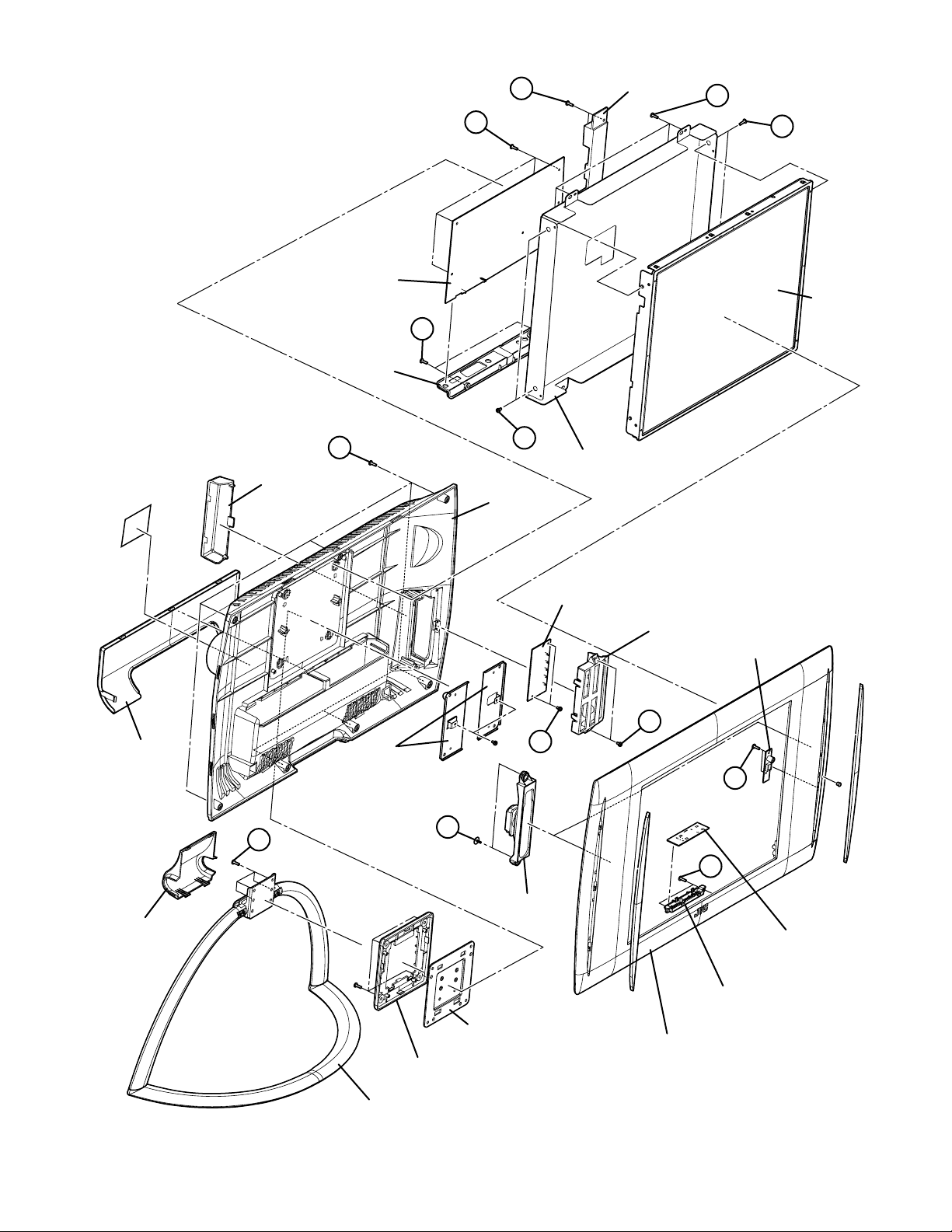
EXPLODED VIEW
10
9
22
23
21
100
14
11
12
102
13
8
103
5
19
18
17
24
16
(X5)
20
15
4
6
(X2)
3
1
7
101
2
(No.YA306)3-3
Page 37

PRINTED WIRING BOARD PARTS LIST
Ref No. Part No. Part Name Description Local
Ref No. Part No. Part Name Description Local
IC10 VE-30031033 PREAMPLIFIER TFMS5360
IC100 VE-30027986 IC
IC101 VE-20214313 IC(MEMORY) (SERVICE)
IC102 VE-20184647 IC(MICOM) (SERVICE)
IC175 VE-30029845 IC
IC176 VE-30040058 IC
IC177 VE-30026744 IC
IC203 VE-30028012 IC
IC400 VE-30018006 IC
IC401 VE-30010024 IC
IC403 VE-30010807 IC
IC404 VE-30010822 IC
IC405 VE-30019372 IC
IC410 VE-30031912 IC
IC411 VE-30031912 IC
IC500 VE-30017956 IC
IC501 VE-30020607 IC
IC502 VE-30017956 IC
IC503 VE-30017956 IC
IC504 VE-30020607 IC
IC505 VE-30028675 IC
Q200 VE-30001454 TRANSISTOR
Q203 VE-30001452 TRANSISTOR
Q204 VE-30001457 TRANSISTOR
Q205 VE-30001457 TRANSISTOR
Q206 VE-30024724 TRANSISTOR
Q207 VE-30001457 TRANSISTOR
Q208 VE-30001457 TRANSISTOR
Q209 VE-30001452 TRANSISTOR
Q210 VE-30024724 TRANSISTOR
Q211 VE-30029775 TRANSISTOR
Q212 VE-30029775 TRANSISTOR
Q213 VE-30001457 TRANSISTOR
Q400 VE-30001457 TRANSISTOR
Q401 VE-30001457 TRANSISTOR
Q402 VE-30001458 TRANSISTOR
Q403 VE-30001457 TRANSISTOR
Q404 VE-30001457 TRANSISTOR
Q405 VE-30001457 TRANSISTOR
Q406 VE-30001457 TRANSISTOR
Q407 VE-30001457 TRANSISTOR
Q409 VE-30001458 TRANSISTOR
Q410 VE-30001457 TRANSISTOR
Q500 VE-30001457 TRANSISTOR
Q502 VE-30001457 TRANSISTOR
Q503 VE-30001457 TRANSISTOR
Q504 VE-30018060 TRANSISTOR
Q505 VE-30018060 TRANSISTOR
D10 VE-30040560 LED
D175 VE-30001285 DIODE
D176 VE-30001285 DIODE
D177 VE-30001285 DIODE
D200 VE-30001285 DIODE
D201 VE-30007169 DIODE
D202 VE-30001377 Z DIODE
D203 VE-30001285 DIODE
D204 VE-30012411 DIODE
D400 VE-30007169 DIODE
D401 VE-30007169 DIODE
D402 VE-30007169 DIODE
D403 VE-30007169 DIODE
D404 VE-30007169 DIODE
D405 VE-30007169 DIODE
D406 VE-30007169 DIODE
D407 VE-30019996 DIODE
D408 VE-30009699 Z DIODE
D409 VE-30009699 Z DIODE
D410 VE-30009699 Z DIODE
D411 VE-30009699 Z DIODE
D412 VE-30009699 Z DIODE
D413 VE-30009699 Z DIODE
D414 VE-30009699 Z DIODE
D415 VE-30009699 Z DIODE
D417 VE-30001285 DIODE
D500 VE-30001313 DIODE
C10 VE-30000371 CAPACITOR EL 22uF 50V M
C100 VE-30012589 CAPACITOR 4.7nF 50V K
C100 VE-30012603 CAPACITOR 100nF 25V K R
C101 VE-30012589 CAPACITOR 4.7nF 50V K
RED/GREEN 5mm 2PIN 20mA
C101 VE-30012603 CAPACITOR 100nF 25V K R
C102 VE-30012560 CAPACITOR 100pF 50V J
C102 VE-30012569 CAPACITOR 33pF 50V J
C103 VE-30012560 CAPACITOR 100pF 50V J
C103 VE-30012569 CAPACITOR 33pF 50V J
C104 VE-30012560 CAPACITOR 100pF 50V J
C104 VE-30016654 CAPACITOR 100nF 16V K R
C105 VE-30012560 CAPACITOR 100pF 50V J
C105 VE-30016654 CAPACITOR 100nF 16V K R
C106 VE-30020694 CAPACITOR 1uF 16V Z Y5V
C107 VE-30020694 CAPACITOR 1uF 16V Z Y5V
C108 VE-30012582 CAPACITOR 10nF 50V K R
C109 VE-30012582 CAPACITOR 10nF 50V K R
C110 VE-30016654 CAPACITOR 100nF 16V K R
C111 VE-30016654 CAPACITOR 100nF 16V K R
C112 VE-30016654 CAPACITOR 100nF 16V K R
C113 VE-30016654 CAPACITOR 100nF 16V K R
C114 VE-30016654 CAPACITOR 100nF 16V K R
C116 VE-30016654 CAPACITOR 100nF 16V K R
C117 VE-30016654 CAPACITOR 100nF 16V K R
C118 VE-30016654 CAPACITOR 100nF 16V K R
C119 VE-30016654 CAPACITOR 100nF 16V K R
C120 VE-30016654 CAPACITOR 100nF 16V K R
C121 VE-30016654 CAPACITOR 100nF 16V K R
C122 VE-30016654 CAPACITOR 100nF 16V K R
C123 VE-30012564 CAPACITOR 18pF 50V J
C124 VE-30016654 CAPACITOR 100nF 16V K R
C125 VE-30012560 CAPACITOR 100pF 50V J
C126 VE-30012610 CAPACITOR 10nF 50V J
C127 VE-30037180 CAPACITOR 3.9nF 50V J R
C128 VE-30037178 CAPACITOR 39nF 25 J
C130 VE-30016654 CAPACITOR 100nF 16V K R
C131 VE-30016654 CAPACITOR 100nF 16V K R
C132 VE-30012560 CAPACITOR 100pF 50V J
C133 VE-30012610 CAPACITOR 10nF 50V J
C134 VE-30016654 CAPACITOR 100nF 16V K R
C135 VE-30016654 CAPACITOR 100nF 16V K R
C136 VE-30012590 CAPACITOR 47nF 50V K
C138 VE-30016654 CAPACITOR 100nF 16V K R
C139 VE-30016654 CAPACITOR 100nF 16V K R
C140 VE-30016654 CAPACITOR 100nF 16V K R
C141 VE-30012590 CAPACITOR 47nF 50V K
C142 VE-30012581 CAPACITOR 1nF 50V K R
C143 VE-30016654 CAPACITOR 100nF 16V K R
C144 VE-30016654 CAPACITOR 100nF 16V K R
C145 VE-30016654 CAPACITOR 100nF 16V K R
C146 VE-30016654 CAPACITOR 100nF 16V K R
C147 VE-30016654 CAPACITOR 100nF 16V K R
C148 VE-30012590 CAPACITOR 47nF 50V K
C149 VE-30016654 CAPACITOR 100nF 16V K R
C151 VE-30016654 CAPACITOR 100nF 16V K R
C154 VE-30012573 CAPACITOR 47pF 50V J
C155 VE-30031604 CAPACITOR NET 10pF 50V F COG
C156 VE-30031604 CAPACITOR NET 10pF 50V F COG
C157 VE-30031604 CAPACITOR NET 10pF 50V F COG
C158 VE-30031604 CAPACITOR NET 10pF 50V F COG
C159 VE-30031604 CAPACITOR NET 10pF 50V F COG
C160 VE-30031604 CAPACITOR NET 10pF 50V F COG
C161 VE-30031604 CAPACITOR NET 10pF 50V F COG
C167 VE-30031604 CAPACITOR NET 10pF 50V F COG
C175 VE-30000352 E CAPACITOR 100uF 16V M
C176 VE-30016654 CAPACITOR 100nF 16V K R
C177 VE-30016654 CAPACITOR 100nF 16V K R
C178 VE-30016654 CAPACITOR 100nF 16V K R
C179 VE-30016654 CAPACITOR 100nF 16V K R
C180 VE-30012582 CAPACITOR 10nF 50V K R
C181 VE-30012582 CAPACITOR 10nF 50V K R
C182 VE-30012582 CAPACITOR 10nF 50V K R
C185 VE-30012582 CAPACITOR 10nF 50V K R
C186 VE-30020694 CAPACITOR 1uF 16V Z Y5V
C188 VE-30012582 CAPACITOR 10nF 50V K R
C189 VE-30020694 CAPACITOR 1uF 16V Z Y5V
C192 VE-30012582 CAPACITOR 10nF 50V K R
C193 VE-30012603 CAPACITOR 100nF 25V K R
C194 VE-30000353 E CAPACITOR 100uF 25V M
C195 VE-30012582 CAPACITOR 10nF 50V K R
C197 VE-30012582 CAPACITOR 10nF 50V K R
C198 VE-30020694 CAPACITOR 1uF 16V Z Y5V
C199 VE-30012603 CAPACITOR 100nF 25V K R
C206 VE-30000400 E CAPACITOR 47uF 50V M
C217 VE-30000345 E CAPACITOR 10uF 50V M
C218 VE-30016654 CAPACITOR 100nF 16V K R
C220 VE-30012603 CAPACITOR 100nF 25V K R
C222 VE-30000352 E CAPACITOR 100uF 16V M
3-4(No.YA306)
Page 38

Ref No. Part No. Part Name Description Local
Ref No. Part No. Part Name Description Local
C223 VE-30000345 E CAPACITOR 10uF 50V M
C225 VE-30012603 CAPACITOR 100nF 25V K R
C231 VE-30012590 CAPACITOR 47nF 50V K
C233 VE-30016654 CAPACITOR 100nF 16V K R
C241 VE-30012589 CAPACITOR 4.7nF 50V K
C242 VE-30016654 CAPACITOR 100nF 16V K R
C244 VE-30016654 CAPACITOR 100nF 16V K R
C245 VE-30016654 CAPACITOR 100nF 16V K R
C246 VE-30016654 CAPACITOR 100nF 16V K R
C249 VE-30016126 CAPACITOR 220nF 16V K R
C250 VE-30000345 E CAPACITOR 10uF 50V M
C252 VE-30012589 CAPACITOR 4.7nF 50V K
C253 VE-30016654 CAPACITOR 100nF 16V K R
C254 VE-30000352 E CAPACITOR 100uF 16V M
C255 VE-30016126 CAPACITOR 220nF 16V K R
C256 VE-30016126 CAPACITOR 220nF 16V K R
C257 VE-30016654 CAPACITOR 100nF 16V K R
C258 VE-30012568 CAPACITOR 270pF 50V J
C259 VE-30016654 CAPACITOR 100nF 16V K R
C260 VE-30016654 CAPACITOR 100nF 16V K R
C261 VE-30000352 E CAPACITOR 100uF 16V M
C262 VE-30016654 CAPACITOR 100nF 16V K R
C263 VE-30012588 CAPACITOR 33nF 50V K
C264 VE-30000352 E CAPACITOR 100uF 16V M
C265 VE-30016654 CAPACITOR 100nF 16V K R
C266 VE-30016126 CAPACITOR 220nF 16V K R
C267 VE-30012588 CAPACITOR 33nF 50V K
C268 VE-30000352 E CAPACITOR 100uF 16V M
C271 VE-30016654 CAPACITOR 100nF 16V K R
C273 VE-30016654 CAPACITOR 100nF 16V K R
C274 VE-30016654 CAPACITOR 100nF 16V K R
C275 VE-30016654 CAPACITOR 100nF 16V K R
C276 VE-30016654 CAPACITOR 100nF 16V K R
C277 VE-30000400 E CAPACITOR 47uF 50V M
C278 VE-30012581 CAPACITOR 1nF 50V K R
C279 VE-30012590 CAPACITOR 47nF 50V K
C281 VE-30016126 CAPACITOR 220nF 16V K R
C282 VE-30016654 CAPACITOR 100nF 16V K R
C283 VE-30016654 CAPACITOR 100nF 16V K R
C284 VE-30016126 CAPACITOR 220nF 16V K R
C285 VE-30016126 CAPACITOR 220nF 16V K R
C286 VE-30016654 CAPACITOR 100nF 16V K R
C287 VE-30016654 CAPACITOR 100nF 16V K R
C288 VE-30016654 CAPACITOR 100nF 16V K R
C289 VE-30016654 CAPACITOR 100nF 16V K R
C290 VE-30016654 CAPACITOR 100nF 16V K R
C292 VE-30000384 E CAPACITOR 2.2uF 50V M
C293 VE-30016654 CAPACITOR 100nF 16V K R
C294 VE-30016654 CAPACITOR 100nF 16V K R
C295 VE-30016654 CAPACITOR 100nF 16V K R
C296 VE-30000352 E CAPACITOR 100uF 16V M
C298 VE-30000384 E CAPACITOR 2.2uF 50V M
C299 VE-30016654 CAPACITOR 100nF 16V K R
C301 VE-30012581 CAPACITOR 1nF 50V K R
C302 VE-30016654 CAPACITOR 100nF 16V K R
C303 VE-30000345 E CAPACITOR 10uF 50V M
C304 VE-30016126 CAPACITOR 220nF 16V K R
C305 VE-30000345 E CAPACITOR 10uF 50V M
C306 VE-30016126 CAPACITOR 220nF 16V K R
C307 VE-30016126 CAPACITOR 220nF 16V K R
C308 VE-30016654 CAPACITOR 100nF 16V K R
C309 VE-30016126 CAPACITOR 220nF 16V K R
C310 VE-30016654 CAPACITOR 100nF 16V K R
C311 VE-30012592 CAPACITOR 6.8nF 50V K
C312 VE-30016654 CAPACITOR 100nF 16V K R
C313 VE-30016126 CAPACITOR 220nF 16V K R
C314 VE-30000092 CAPACITOR MKT 220nF 63V J
C315 VE-30000352 E CAPACITOR 100uF 16V M
C316 VE-30000345 E CAPACITOR 10uF 50V M
C320 VE-30000345 E CAPACITOR 10uF 50V M
C321 VE-30016654 CAPACITOR 100nF 16V K R
C322 VE-30016654 CAPACITOR 100nF 16V K R
C323 VE-30000362 E CAPACITOR 1uF 50V M
C324 VE-30016654 CAPACITOR 100nF 16V K R
C325 VE-30016654 CAPACITOR 100nF 16V K R
C326 VE-30000352 E CAPACITOR 100uF 16V M
C327 VE-30016654 CAPACITOR 100nF 16V K R
C328 VE-30016654 CAPACITOR 100nF 16V K R
C329 VE-30016654 CAPACITOR 100nF 16V K R
C330 VE-30016654 CAPACITOR 100nF 16V K R
C333 VE-30016654 CAPACITOR 100nF 16V K R
C334 VE-30016654 CAPACITOR 100nF 16V K R
C336 VE-30020694 CAPACITOR 1uF 16V Z Y5V
C337 VE-30000345 E CAPACITOR 10uF 50V M
C338 VE-30012582 CAPACITOR 10nF 50V K R
C339 VE-30016654 CAPACITOR 100nF 16V K R
C340 VE-30000393 E CAPACITOR 3.3uF 50V M
C341 VE-30016654 CAPACITOR 100nF 16V K R
C342 VE-30016654 CAPACITOR 100nF 16V K R
C347 VE-30016654 CAPACITOR 100nF 16V K R
C349 VE-30012573 CAPACITOR 47pF 50V J
C350 VE-30012573 CAPACITOR 47pF 50V J
C351 VE-30012573 CAPACITOR 47pF 50V J
C352 VE-30012573 CAPACITOR 47pF 50V J
C353 VE-30012573 CAPACITOR 47pF 50V J
C354 VE-30012573 CAPACITOR 47pF 50V J
C355 VE-30012573 CAPACITOR 47pF 50V J
C356 VE-30012573 CAPACITOR 47pF 50V J
C357 VE-30012573 CAPACITOR 47pF 50V J
C358 VE-30012573 CAPACITOR 47pF 50V J
C359 VE-30012573 CAPACITOR 47pF 50V J
C360 VE-30012573 CAPACITOR 47pF 50V J
C361 VE-30012573 CAPACITOR 47pF 50V J
C364 VE-30012573 CAPACITOR 47pF 50V J
C365 VE-30012573 CAPACITOR 47pF 50V J
C366 VE-30012573 CAPACITOR 47pF 50V J
C367 VE-30012573 CAPACITOR 47pF 50V J
C368 VE-30012573 CAPACITOR 47pF 50V J
C369 VE-30012573 CAPACITOR 47pF 50V J
C370 VE-30012573 CAPACITOR 47pF 50V J
C400 VE-30016654 CAPACITOR 100nF 16V K R
C403 VE-30012560 CAPACITOR 100pF 50V J
C404 VE-30012560 CAPACITOR 100pF 50V J
C405 VE-30012560 CAPACITOR 100pF 50V J
C406 VE-30012581 CAPACITOR 1nF 50V K R
C407 VE-30012581 CAPACITOR 1nF 50V K R
C410 VE-30012559 CAPACITOR 10pF 50V D COG
C413 VE-30012559 CAPACITOR 10pF 50V D COG
C414 VE-30012559 CAPACITOR 10pF 50V D COG
C415 VE-30012581 CAPACITOR 1nF 50V K R
C416 VE-30012581 CAPACITOR 1nF 50V K R
C417 VE-30012581 CAPACITOR 1nF 50V K R
C418 VE-30012581 CAPACITOR 1nF 50V K R
C419 VE-30012560 CAPACITOR 100pF 50V J
C420 VE-30012560 CAPACITOR 100pF 50V J
C421 VE-30012560 CAPACITOR 100pF 50V J
C422 VE-30016654 CAPACITOR 100nF 16V K R
C423 VE-30016654 CAPACITOR 100nF 16V K R
C424 VE-30016654 CAPACITOR 100nF 16V K R
C425 VE-30012560 CAPACITOR 100pF 50V J
C426 VE-30012588 CAPACITOR 33nF 50V K
C427 VE-30012560 CAPACITOR 100pF 50V J
C428 VE-30012560 CAPACITOR 100pF 50V J
C429 VE-30012581 CAPACITOR 1nF 50V K R
C430 VE-30012581 CAPACITOR 1nF 50V K R
C431 VE-30012573 CAPACITOR 47pF 50V J
C432 VE-30012573 CAPACITOR 47pF 50V J
C433 VE-30012573 CAPACITOR 47pF 50V J
C434 VE-30000345 E CAPACITOR 10uF 50V M
C435 VE-30000345 E CAPACITOR 10uF 50V M
C436 VE-30000345 E CAPACITOR 10uF 50V M
C437 VE-30000345 E CAPACITOR 10uF 50V M
C438 VE-30016654 CAPACITOR 100nF 16V K R
C439 VE-30016654 CAPACITOR 100nF 16V K R
C440 VE-30012568 CAPACITOR 270pF 50V J
C441 VE-30012568 CAPACITOR 270pF 50V J
C442 VE-30000345 E CAPACITOR 10uF 50V M
C443 VE-30012581 CAPACITOR 1nF 50V K R
C444 VE-30012568 CAPACITOR 270pF 50V J
C445 VE-30000352 E CAPACITOR 100uF 16V M
C449 VE-30024768 CAPACITOR 470nF 16V Z
C450 VE-30000353 E CAPACITOR 100uF 25V M
C451 VE-30024768 CAPACITOR 470nF 16V Z
C453 VE-30020694 CAPACITOR 1uF 16V Z Y5V
C455 VE-30020694 CAPACITOR 1uF 16V Z Y5V
C457 VE-30016654 CAPACITOR 100nF 16V K R
C459 VE-30000345 E CAPACITOR 10uF 50V M
C460 VE-30012568 CAPACITOR 270pF 50V J
C461 VE-30012560 CAPACITOR 100pF 50V J
C462 VE-30012568 CAPACITOR 270pF 50V J
C463 VE-30012603 CAPACITOR 100nF 25V K R
C464 VE-30012603 CAPACITOR 100nF 25V K R
C466 VE-30000345 E CAPACITOR 10uF 50V M
C467 VE-30000407 E CAPACITOR 470uF 16V M
C471 VE-30016654 CAPACITOR 100nF 16V K R
C472 VE-30000352 E CAPACITOR 100uF 16V M
C473 VE-30012560 CAPACITOR 100pF 50V J
C474 VE-30000352 E CAPACITOR 100uF 16V M
C475 VE-30012589 CAPACITOR 4.7nF 50V K
C476 VE-30012589 CAPACITOR 4.7nF 50V K
C477 VE-30020694 CAPACITOR 1uF 16V Z Y5V
C478 VE-30016654 CAPACITOR 100nF 16V K R
C479 VE-30016654 CAPACITOR 100nF 16V K R
C484 VE-30012509 RESISTOR 1/16W 100K J
(No.YA306)3-5
Page 39

Ref No. Part No. Part Name Description Local
Ref No. Part No. Part Name Description Local
C501 VE-30016654 CAPACITOR 100nF 16V K R
C502 VE-30016654 CAPACITOR 100nF 16V K R
C503 VE-30016654 CAPACITOR 100nF 16V K R
C504 VE-30016654 CAPACITOR 100nF 16V K R
C505 VE-30016654 CAPACITOR 100nF 16V K R
C506 VE-30000352 E CAPACITOR 100uF 16V M
C507 VE-30000352 E CAPACITOR 100uF 16V M
C508 VE-30000352 E CAPACITOR 100uF 16V M
C510 VE-30000352 E CAPACITOR 100uF 16V M
C511 VE-30016654 CAPACITOR 100nF 16V K R
C512 VE-30016654 CAPACITOR 100nF 16V K R
C513 VE-30016654 CAPACITOR 100nF 16V K R
C514 VE-30016654 CAPACITOR 100nF 16V K R
C515 VE-30016654 CAPACITOR 100nF 16V K R
C516 VE-30016654 CAPACITOR 100nF 16V K R
C517 VE-30016654 CAPACITOR 100nF 16V K R
C518 VE-30016654 CAPACITOR 100nF 16V K R
C519 VE-30016654 CAPACITOR 100nF 16V K R
C520 VE-30016654 CAPACITOR 100nF 16V K R
C521 VE-30000407 E CAPACITOR 470uF 16V M
C522 VE-30000352 E CAPACITOR 100uF 16V M
C523 VE-30000352 E CAPACITOR 100uF 16V M
C524 VE-30000352 E CAPACITOR 100uF 16V M
C525 VE-30000352 E CAPACITOR 100uF 16V M
C526 VE-30000352 E CAPACITOR 100uF 16V M
C527 VE-30012603 CAPACITOR 100nF 25V K R
C528 VE-30012603 CAPACITOR 100nF 25V K R
C529 VE-30016654 CAPACITOR 100nF 16V K R
C531 VE-30000352 E CAPACITOR 100uF 16V M
C532 VE-30012603 CAPACITOR 100nF 25V K R
C533 VE-30012574 CAPACITOR 470pF 50V J
C534 VE-30012603 CAPACITOR 100nF 25V K R
C535 VE-30000345 E CAPACITOR 10uF 50V M
C536 VE-30016654 CAPACITOR 100nF 16V K R
C537 VE-30016654 CAPACITOR 100nF 16V K R
C538 VE-30012603 CAPACITOR 100nF 25V K R
C539 VE-30016654 CAPACITOR 100nF 16V K R
C540 VE-30016654 CAPACITOR 100nF 16V K R
C541 VE-30000359 E CAPACITOR 1000uF 16V M
C542 VE-30000407 E CAPACITOR 470uF 16V M
C543 VE-30016654 CAPACITOR 100nF 16V K R
C544 VE-30000352 E CAPACITOR 100uF 16V M
C545 VE-30016126 CAPACITOR 220nF 16V K R
R1 VE-30000459 RESISTOR CF 1/4W 100R J
R100 VE-30012510 RESISTOR 1/16W 100R J
R101 VE-30012510 RESISTOR 1/16W 100R J
R102 VE-30012641 RESISTOR 1/16W 10K J
R103 VE-30012641 RESISTOR 1/16W 10K J
R103 VE-30012677 RESISTOR 1/16W 3.3K J
R104 VE-30012641 RESISTOR 1/16W 10K J
R105 VE-30012641 RESISTOR 1/16W 10K J
R106 VE-30012677 RESISTOR 1/16W 3.3K J
R107 VE-30012677 RESISTOR 1/16W 3.3K J
R108 VE-30012677 RESISTOR 1/16W 3.3K J
R109 VE-30012507 RESISTOR 1/16W 1.5M J
R110 VE-30012677 RESISTOR 1/16W 3.3K J
R111 VE-30012510 RESISTOR 1/16W 100R J
R112 VE-30012510 RESISTOR 1/16W 100R J
R113 VE-30012510 RESISTOR 1/16W 100R J
R114 VE-30012510 RESISTOR 1/16W 100R J
R115 VE-30012510 RESISTOR 1/16W 100R J
R116 VE-30012510 RESISTOR 1/16W 100R J
R117 VE-30012677 RESISTOR 1/16W 3.3K J
R118 VE-30012677 RESISTOR 1/16W 3.3K J
R123 VE-30012641 RESISTOR 1/16W 10K J
R124 VE-30012641 RESISTOR 1/16W 10K J
R125 VE-30012641 RESISTOR 1/16W 10K J
R126 VE-30012641 RESISTOR 1/16W 10K J
R127 VE-30012677 RESISTOR 1/16W 3.3K J
R134 VE-30017653 RESISTOR SARRAY 1/16W 47RX4 J
R135 VE-30020529 FERRITE 120R/100MHz 200mA
R136 VE-30012677 RESISTOR 1/16W 3.3K J
R137 VE-30012677 RESISTOR 1/16W 3.3K J
R138 VE-30012677 RESISTOR 1/16W 3.3K J
R141 VE-30030692 FERRITE NET 120R/100MHz 150mA
R142 VE-30030692 FERRITE NET 120R/100MHz 150mA
R143 VE-30030692 FERRITE NET 120R/100MHz 150mA
R144 VE-30030692 FERRITE NET 120R/100MHz 150mA
R145 VE-30030692 FERRITE NET 120R/100MHz 150mA
R146 VE-30030692 FERRITE NET 120R/100MHz 150mA
R147 VE-30030692 FERRITE NET 120R/100MHz 150mA
R149 VE-30012510 RESISTOR 1/16W 100R J
R152 VE-30012510 RESISTOR 1/16W 100R J
R153 VE-30012510 RESISTOR 1/16W 100R J
R154 VE-30012510 RESISTOR 1/16W 100R J
R155 VE-30012510 RESISTOR 1/16W 100R J
R156 VE-30012692 RESISTOR 1/16W 4.7K J
R175 VE-30012641 RESISTOR 1/16W 10K J
R176 VE-30012641 RESISTOR 1/16W 10K J
R177 VE-30012641 RESISTOR 1/16W 10K J
R178 VE-30012641 RESISTOR 1/16W 10K J
R179 VE-30012641 RESISTOR 1/16W 10K J
R180 VE-30012641 RESISTOR 1/16W 10K J
R181 VE-30012641 RESISTOR 1/16W 10K J
R182 VE-30012641 RESISTOR 1/16W 10K J
R183 VE-30012641 RESISTOR 1/16W 10K J
R184 VE-30012641 RESISTOR 1/16W 10K J
R185 VE-30012510 RESISTOR 1/16W 100R J
R186 VE-30012510 RESISTOR 1/16W 100R J
R187 VE-30012641 RESISTOR 1/16W 10K J
R188 VE-30012641 RESISTOR 1/16W 10K J
R190 VE-30012510 RESISTOR 1/16W 100R J
R191 VE-30012641 RESISTOR 1/16W 10K J
R192 VE-30012641 RESISTOR 1/16W 10K J
R193 VE-30012641 RESISTOR 1/16W 10K J
R194 VE-30012641 RESISTOR 1/16W 10K J
R206 VE-30012669 RESISTOR 1/16W 22K J
R207 VE-30012708 RESISTOR 1/16W 68K J
R208 VE-30012641 RESISTOR 1/16W 10K J
R211 VE-30012510 RESISTOR 1/16W 100R J
R213 VE-30012510 RESISTOR 1/16W 100R J
R216 VE-30000464 RESISTOR 1/10W 100R J
R217 VE-30000464 RESISTOR 1/10W 100R J
R224 VE-30012641 RESISTOR 1/16W 10K J
R225 VE-30012692 RESISTOR 1/16W 4.7K J
R226 VE-30012692 RESISTOR 1/16W 4.7K J
R227 VE-30012510 RESISTOR 1/16W 100R J
R228 VE-30012510 RESISTOR 1/16W 100R J
R229 VE-30012510 RESISTOR 1/16W 100R J
R230 VE-30012674 RESISTOR 1/16W 27K J
R231 VE-30012982 RESISTOR 1/16W 10R J
R232 VE-30012696 RESISTOR 1/16W 47K J
R233 VE-30012641 RESISTOR 1/16W 10K J
R234 VE-30000706 RESISTOR CF 1/4W 47R J
R235 VE-30012677 RESISTOR 1/16W 3.3K J
R236 VE-30012510 RESISTOR 1/16W 100R J
R237 VE-30012510 RESISTOR 1/16W 100R J
R238 VE-30012510 RESISTOR 1/16W 100R J
R239 VE-30012677 RESISTOR 1/16W 3.3K J
R243 VE-30012692 RESISTOR 1/16W 4.7K J
R244 VE-30012692 RESISTOR 1/16W 4.7K J
R245 VE-30012677 RESISTOR 1/16W 3.3K J
R246 VE-30012677 RESISTOR 1/16W 3.3K J
R248 VE-30012510 RESISTOR 1/16W 100R J
R250 VE-30012510 RESISTOR 1/16W 100R J
R251 VE-30012510 RESISTOR 1/16W 100R J
R254 VE-30012510 RESISTOR 1/16W 100R J
R255 VE-30012684 RESISTOR 1/16W 330R J
R256 VE-30012688 RESISTOR 1/16W 390R J
R257 VE-30012510 RESISTOR 1/16W 100R J
R258 VE-30012692 RESISTOR 1/16W 4.7K J
R259 VE-30012641 RESISTOR 1/16W 10K J
R260 VE-30012510 RESISTOR 1/16W 100R J
R261 VE-30012510 RESISTOR 1/16W 100R J
R262 VE-30012684 RESISTOR 1/16W 330R J
R263 VE-30012684 RESISTOR 1/16W 330R J
R264 VE-30012657 RESISTOR 1/16W 1K J
R265 VE-30012657 RESISTOR 1/16W 1K J
R266 VE-30012509 RESISTOR 1/16W 100K J
R267 VE-30012689 RESISTOR 1/16W 39K J
R268 VE-30012507 RESISTOR 1/16W 1.5M J
R269 VE-30012692 RESISTOR 1/16W 4.7K J
R270 VE-30012657 RESISTOR 1/16W 1K J
R271 VE-30012644 RESISTOR 1/16W 12K J
R272 VE-30015578 RESISTOR 1/16W 2.2R J
R273 VE-30012696 RESISTOR 1/16W 47K J
R274 VE-30015578 RESISTOR 1/16W 2.2R J
R275 VE-30012644 RESISTOR 1/16W 12K J
R276 VE-30012641 RESISTOR 1/16W 10K J
R277 VE-30012707 RESISTOR 1/16W 680R J
R278 VE-30012692 RESISTOR 1/16W 4.7K J
R279 VE-30012657 RESISTOR 1/16W 1K J
R280 VE-30012696 RESISTOR 1/16W 47K J
R281 VE-30012648 RESISTOR 1/16W 150K J
R282 VE-30012692 RESISTOR 1/16W 4.7K J
R283 VE-30012641 RESISTOR 1/16W 10K J
R284 VE-30012641 RESISTOR 1/16W 10K J
R285 VE-30015578 RESISTOR 1/16W 2.2R J
R286 VE-30012510 RESISTOR 1/16W 100R J
R287 VE-30012641 RESISTOR 1/16W 10K J
R288 VE-30015578 RESISTOR 1/16W 2.2R J
R289 VE-30012641 RESISTOR 1/16W 10K J
R290 VE-30012669 RESISTOR 1/16W 22K J
3-6(No.YA306)
Page 40

Ref No. Part No. Part Name Description Local
Ref No. Part No. Part Name Description Local
R291 VE-30012657 RESISTOR 1/16W 1K J
R292 VE-30012510 RESISTOR 1/16W 100R J
R293 VE-30012510 RESISTOR 1/16W 100R J
R294 VE-30012696 RESISTOR 1/16W 47K J
R297 VE-30012641 RESISTOR 1/16W 10K J
R298 VE-30012641 RESISTOR 1/16W 10K J
R310 VE-30012668 RESISTOR 1/16W 220R J
R311 VE-30012668 RESISTOR 1/16W 220R J
R400 VE-30000797 RESISTOR 1/10W 75R J
R401 VE-30000797 RESISTOR 1/10W 75R J
R402 VE-30000797 RESISTOR 1/10W 75R J
R403 VE-30012510 RESISTOR 1/16W 100R J
R404 VE-30012510 RESISTOR 1/16W 100R J
R405 VE-30012510 RESISTOR 1/16W 100R J
R406 VE-30000469 RESISTOR 1/10W 1K J
R407 VE-30000469 RESISTOR 1/10W 1K J
R413 VE-30000797 RESISTOR 1/10W 75R J
R414 VE-30012677 RESISTOR 1/16W 3.3K J
R415 VE-30012668 RESISTOR 1/16W 220R J
R416 VE-30000797 RESISTOR 1/10W 75R J
R417 VE-30012677 RESISTOR 1/16W 3.3K J
R418 VE-30012668 RESISTOR 1/16W 220R J
R419 VE-30000797 RESISTOR 1/10W 75R J
R422 VE-30000469 RESISTOR 1/10W 1K J
R423 VE-30012510 RESISTOR 1/16W 100R J
R424 VE-30012510 RESISTOR 1/16W 100R J
R425 VE-30012510 RESISTOR 1/16W 100R J
R429 VE-30000797 RESISTOR 1/10W 75R J
R430 VE-30000469 RESISTOR 1/10W 1K J
R431 VE-30000797 RESISTOR 1/10W 75R J
R432 VE-30000475 RESISTOR 1/10W 10K J
R433 VE-30012677 RESISTOR 1/16W 3.3K J
R434 VE-30000797 RESISTOR 1/10W 75R J
R435 VE-30000797 RESISTOR 1/10W 75R J
R436 VE-30012510 RESISTOR 1/16W 100R J
R437 VE-30012659 RESISTOR 1/16W 2.2K J
R438 VE-30012707 RESISTOR 1/16W 680R J
R439 VE-30012510 RESISTOR 1/16W 100R J
R440 VE-30012648 RESISTOR 1/16W 150K J
R441 VE-30012641 RESISTOR 1/16W 10K J
R442 VE-30012641 RESISTOR 1/16W 10K J
R443 VE-30000797 RESISTOR 1/10W 75R J
R444 VE-30000797 RESISTOR 1/10W 75R J
R445 VE-30012657 RESISTOR 1/16W 1K J
R446 VE-30012674 RESISTOR 1/16W 27K J
R447 VE-30012657 RESISTOR 1/16W 1K J
R448 VE-30012692 RESISTOR 1/16W 4.7K J
R449 VE-30012641 RESISTOR 1/16W 10K J
R450 VE-30012692 RESISTOR 1/16W 4.7K J
R451 VE-30012641 RESISTOR 1/16W 10K J
R452 VE-30012692 RESISTOR 1/16W 4.7K J
R453 VE-30012641 RESISTOR 1/16W 10K J
R454 VE-30012982 RESISTOR 1/16W 10R J
R455 VE-30012510 RESISTOR 1/16W 100R J
R459 VE-30012713 RESISTOR 1/16W 75R J
R460 VE-30012713 RESISTOR 1/16W 75R J
R461 VE-30012713 RESISTOR 1/16W 75R J
R462 VE-30012705 RESISTOR 1/16W 6.8K J
R463 VE-30012713 RESISTOR 1/16W 75R J
R464 VE-30012713 RESISTOR 1/16W 75R J
R465 VE-30012644 RESISTOR 1/16W 12K J
R466 VE-30012644 RESISTOR 1/16W 12K J
R467 VE-30012713 RESISTOR 1/16W 75R J
R468 VE-30012705 RESISTOR 1/16W 6.8K J
R469 VE-30012705 RESISTOR 1/16W 6.8K J
R470 VE-30012685 RESISTOR 1/16W 33K J
R471 VE-30012685 RESISTOR 1/16W 33K J
R472 VE-30012713 RESISTOR 1/16W 75R J
R473 VE-30012648 RESISTOR 1/16W 150K J
R474 VE-30012689 RESISTOR 1/16W 39K J
R475 VE-30012641 RESISTOR 1/16W 10K J
R476 VE-30012641 RESISTOR 1/16W 10K J
R477 VE-30012713 RESISTOR 1/16W 75R J
R478 VE-30012689 RESISTOR 1/16W 39K J
R479 VE-30012692 RESISTOR 1/16W 4.7K J
R480 VE-30012696 RESISTOR 1/16W 47K J
R481 VE-30012648 RESISTOR 1/16W 150K J
R485 VE-30012641 RESISTOR 1/16W 10K J
R487 VE-30000464 RESISTOR 1/10W 100R J
R488 VE-30000464 RESISTOR 1/10W 100R J
R489 VE-30000464 RESISTOR 1/10W 100R J
R495 VE-30012668 RESISTOR 1/16W 220R J
R496 VE-30012669 RESISTOR 1/16W 22K J
R503 VE-30012641 RESISTOR 1/16W 10K J
R505 VE-30012669 RESISTOR 1/16W 22K J
R506 VE-30012669 RESISTOR 1/16W 22K J
R507 VE-30012648 RESISTOR 1/16W 150K J
R508 VE-30012641 RESISTOR 1/16W 10K J
R509 VE-30012509 RESISTOR 1/16W 100K J
R510 VE-30012705 RESISTOR 1/16W 6.8K J
R511 VE-30012641 RESISTOR 1/16W 10K J
R512 VE-30012669 RESISTOR 1/16W 22K J
R513 VE-30012641 RESISTOR 1/16W 10K J
R514 VE-30012692 RESISTOR 1/16W 4.7K J
R550 VE-30012685 RESISTOR 1/16W 33K J
R551 VE-30012685 RESISTOR 1/16W 33K J
L100 VE-30001996 FIXED COIL 22uH Q40 K
L100 VE-30001971 FERRITE 600R/100MHz 200mA
L101 VE-30001996 FIXED COIL 22uH Q40 K
L101 VE-30001971 FERRITE 600R/100MHz 200mA
L102 VE-30001979 FIXED COIL 1uH Q45 M-A
L102 VE-30001971 FERRITE 600R/100MHz 200mA
L103 VE-30006712 FERRITE BEAD 3.5X4.7X0.8
L103 VE-30001971 FERRITE 600R/100MHz 200mA
L104 VE-30001971 FERRITE 600R/100MHz 200mA
L177 VE-30006712 FERRITE BEAD 3.5X4.7X0.8
L179 VE-30001971 FERRITE 600R/100MHz 200mA
L180 VE-30001971 FERRITE 600R/100MHz 200mA
L181 VE-30020531 FERRITE 220R/100MHz 2A
L182 VE-30001971 FERRITE 600R/100MHz 200mA
L183 VE-30020531 FERRITE 220R/100MHz 2A
L201 VE-30001971 FERRITE 600R/100MHz 200mA
L203 VE-30001971 FERRITE 600R/100MHz 200mA
L204 VE-30002002 FIXED COIL 47uH Q60 K
L206 VE-30001971 FERRITE 600R/100MHz 200mA
L207 VE-30002002 FIXED COIL 47uH Q60 K
L208 VE-30001971 FERRITE 600R/100MHz 200mA
L209 VE-30001971 FERRITE 600R/100MHz 200mA
L210 VE-30001971 FERRITE 600R/100MHz 200mA
L211 VE-30001971 FERRITE 600R/100MHz 200mA
L212 VE-30001971 FERRITE 600R/100MHz 200mA
L213 VE-30001971 FERRITE 600R/100MHz 200mA
L214 VE-30001971 FERRITE 600R/100MHz 200mA
L215 VE-30001971 FERRITE 600R/100MHz 200mA
L216 VE-30001971 FERRITE 600R/100MHz 200mA
L217 VE-30001971 FERRITE 600R/100MHz 200mA
L218 VE-30001971 FERRITE 600R/100MHz 200mA
L219 VE-30001971 FERRITE 600R/100MHz 200mA
L220 VE-30001971 FERRITE 600R/100MHz 200mA
L221 VE-30029701 FIXED COIL 0.56uH K
L411 VE-30001971 FERRITE 600R/100MHz 200mA
L412 VE-30001971 FERRITE 600R/100MHz 200mA
L413 VE-30001971 FERRITE 600R/100MHz 200mA
L414 VE-30001971 FERRITE 600R/100MHz 200mA
L415 VE-30001971 FERRITE 600R/100MHz 200mA
L422 VE-30016162 FERRITE 1K/100MHz 200mA
L423 VE-30016162 FERRITE 1K/100MHz 200mA
L424 VE-30001971 FERRITE 600R/100MHz 200mA
L500 VE-30020531 FERRITE 220R/100MHz 2A
L501 VE-30020531 FERRITE 220R/100MHz 2A
L502 VE-30020531 FERRITE 220R/100MHz 2A
L503 VE-30020531 FERRITE 220R/100MHz 2A
L504 VE-30020531 FERRITE 220R/100MHz 2A
L505 VE-30006712 FERRITE BEAD 3.5X4.7X0.8
L506 VE-30019475 FIXED COIL 47uH 2A RAD SH 14X16
L507 VE-30020531 FERRITE 220R/100MHz 2A
L508 VE-30020531 FERRITE 220R/100MHz 2A
L509 VE-30011450 FIXED COIL 22uH 5.4A 11.5*15.5
F501 VE-30035282 FUSE 5A/32VDC
F502 VE-30028331 FUSE 7A/32VDC 1206
JK100 VE-30031077 HEADPHONE JACK HP01/2/3/4/5/6
JK101 VE-30032639 RCA JACK 1P YELLOW 28 FAV
JK102 VE-30032636 RCA JACK 1P WHITE 28 FAV
JK103 VE-30032638 RCA JACK 1P RED 28 FAV
JK104 VE-30001895 JACK 4P DIN TYPE FOR SVHS
JK406 VE-30001902 HEADPHONE JACK STEREO WO/SW
JK500 VE-30027932
PL1 VE-30037369
PL2 VE-30039003
PL100 VE-30001838 CONN HEADER
PL100 VE-30033112 CONN HEADER 4P 2.5MM TOP WHT SD
PL101 VE-30030582 CONN MALE 6P MOLEX VERTICAL
PL102 VE-30030582 CONN MALE 6P MOLEX VERTICAL
PL175 VE-30032885 CONN HEADER 10P 2.54MM TOP WHT
PL176 VE-30018047 CONN HEADER 11P 1.25MM SIDE
PL179 VE-30018073 CONN HEA.
PL201 VE-30032635 CONN HEADER 6P 2.5MM TOP WHT SD
PL203 VE-30031582 CONN HEADER 5P 2.5MM TOP WHT SD
PL400 VE-30032051 D SOCKET D-SUB 15P FOR TFT
PL401 VE-30018089
PL402 VE-30031051 CONN HEADER 2P 2.5MM TOP WHT SD
PL403 VE-30031054 CONN HEADER 2P 2.5MM TOP BLUE SD
DC POWER SOCKET 7.5A
CNAS 10P-5-4/370 FLT W/C UL2468AWG24
CNAS 5P-6/430 FLT W/C UL2468AWG24
SOCET SCART BLACK TFT
3P 2.5MM TOP YELLOW SD
20P 1.25MM SIDE WHT SMT
(No.YA306)3-7
Page 41

Ref No. Part No. Part Name Description Local
PL405 VE-30030582 CONN MALE 6P MOLEX VERTICAL
PL406 VE-30030582 CONN MALE 6P MOLEX VERTICAL
PL407 VE-30001838 CONN HEADER
PL501 VE-30010030 PIN HEADER (1X2)
S187 VE-30041653 FERRITE 60R/100MHz 300mA
S188 VE-30041653 FERRITE 60R/100MHz 300mA
S189 VE-30041653 FERRITE 60R/100MHz 300mA
S190 VE-30041653 FERRITE 60R/100MHz 300mA
S191 VE-30041653 FERRITE 60R/100MHz 300mA
S192 VE-30041653 FERRITE 60R/100MHz 300mA
S193 VE-30041653 FERRITE 60R/100MHz 300mA
S194 VE-30041653 FERRITE 60R/100MHz 300mA
S195 VE-30041653 FERRITE 60R/100MHz 300mA
S196 VE-30041653 FERRITE 60R/100MHz 300mA
S416 VE-30000469 RESISTOR 1/10W 1K J
S417 VE-30000469 RESISTOR 1/10W 1K J
SW5 VE-30032684 TACT SWITCH
TU200 VE-30029452 TUNER WSP (PLL) 38.9 HOR. IEC-L
X100 VE-30017946 CLYSTAL 14.318 MHZ
X201 VE-30001741 CLYSTAL 24.576 20p HC49U
Z200 VE-30012545 SAW FILTER K9656M
Z201 VE-30001692 SAW FILTER OFWK3953M
3P 2.5MM TOP YELLOW SD
3-8(No.YA306)
Page 42

PAC KI N G
4 5 6
7 8
9
3
10
2
1
PACKING PARTS LIST
Ref.No. Part No. Part Name Description Local
1 VE-50069373 CARTON BOX LT-15 B60SJ
1 VE-50069196 CARTON BOX LT-15 B60SW
2 VE-20176204 SNOW BOX (FRONT)
3 VE-20176203 SNOW BOX (BACK)
4 VE-30039453 REMOTE CONTROL UNIT (RM-C1861)
5 VE-30034459 AC ADAPTOR DC12V 4A
6 VE-30002376 POWER CORD For AC ADAPTOR
7 VE-50069375 INST BOOK [ENG] LT-15B60SJ
7 VE-50069198 INST BOOK [ENG/GER/FRA/ITA] LT-15B60SW
7 VE-50069199 INST BOOK [SPA/POR/DUT] LT-15B60SW
8 VE-50069376 WARRANTY CARD LT-15B60SJ
8 VE-50069200 WARRANTY CARD LT-15B60SW
9 ----------- BATTERY AA/R06 (x2)
10 VE-50018337 POLY BAG
(No.YA306)3-9
 Loading...