

Page 1
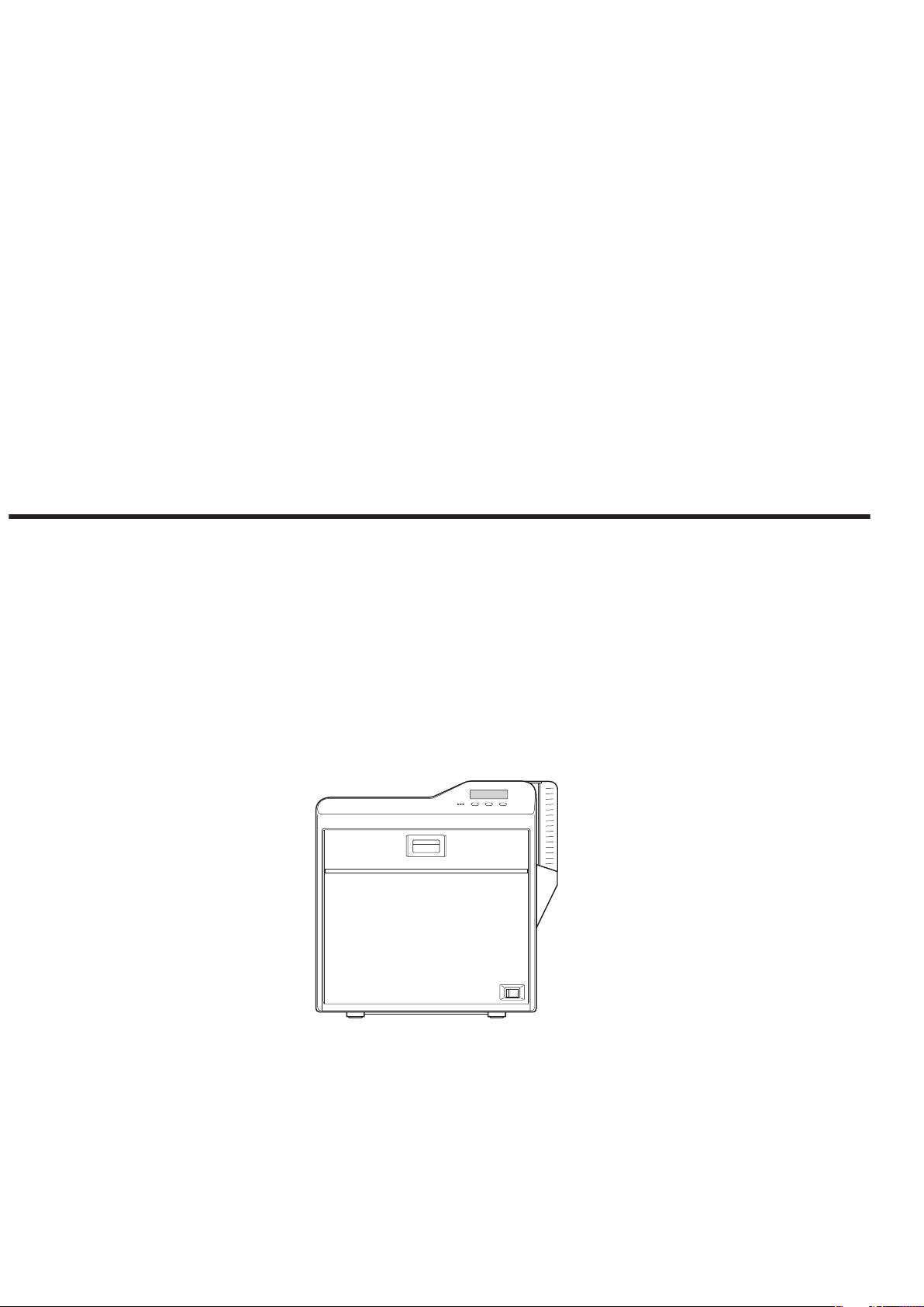
Card Printer
CX-7000 Series
Electronic
Manual
Thank you for purchasing this product.
Please read through this “Electronic Manual”
carefully in advance to ensure proper use of the
product. Also, to make sure that the product is
used safely, please read through the “Safety
Precautions” in the “READ ME FIRST” booklet.
Please store the manuals properly after reading
so that they can be referred to whenever
necessary.
LST1006-002A
Page 2

Contents
Before Use
About this Manual ................................................................ 3
Precautions .......................................................................... 3
Disclaimer ............................................................................ 7
Name and Functions of Parts .............................................. 7
Specifications ..................................................................... 10
Accessories/Products Sold Separately .............................. 10
Options .............................................................................. 11
Operating the Printer
Printing a Card ................................................................... 12
Operation Panel ................................................................. 13
Setting Mode ...................................................................... 15
Sequence of Setting Modes ........................................... 17
Factory Settings ............................................................. 19
Security Lock ..................................................................... 20
Setting Using the Operation Panel .................................... 22
Setting Using the Status Monitor ....................................... 30
Replacement
Cards ................................................................................. 31
Ink Ribbon .......................................................................... 32
Retransfer Film .................................................................. 33
Maintenance
Servicing of Parts ............................................................... 35
Servicing Based on Print Output ........................................ 43
Troubleshooting
When an Error Message is Displayed ............................... 44
Cards ................................................................................. 46
Ink Ribbon .......................................................................... 54
Retransfer Film .................................................................. 56
Unable to Produce Desired Printing Results ..................... 57
Printer not Operating as Desired ....................................... 58
Before Sending Printer for Repair ...................................... 58
Setup
Installation and Connection ............................................... 59
Printing Media .................................................................... 60
Printer and Computer Connection ..................................... 64
Computer Settings ............................................................. 65
Software ......................................................................... 65
Install .............................................................................. 65
Uninstall ......................................................................... 80
IPSec .............................................................................. 84
Printer Driver Settings .................................................... 87
Port Monitor Settings .................................................... 106
Status Monitor Settings ................................................ 107
Inline Encoding ............................................................. 118
List of Error Codes ....................................................... 120
Frequently Asked Questions ........................................ 123
2
Page 3
Batch Print
Print
Before Use
About this Manual
Contents of this Manual
v
The copyright of this manual belongs to our company. Reprint and
duplicate of this manual in part or full without the prior consent of our
company is strictly prohibited.
v
Product names of other companies described in the manual are the
trademarks or registered trademarks of the respective companies.
Symbols such as ™, W and Q are omitted in this manual.
v
Designs, specifications, or other details described in this manual
may be modified for improvement without prior notice.
v
Microsoft and Windows are either registered trademarks or
trademarks of Microsoft Corporation in the United States and/or
other countries. MicrosoftW Windows Vista™ operating system,
MicrosoftW WindowsW XP operating system and MicrosoftW
WindowsW 2000 operating system are represented as Windows
Vista, Windows XP and Windows 2000 respectively in this manual.
v
Microsoft product screen shot(s) reprinted with permission from
Microsoft Corporation.
v
This product includes software developed by the OpenSSL Project
for use in the OpenSSL Toolkit. (http://www.openssl.org/)
This product includes cryptographic software written by Eric Young
(eay@cryptsoft.com).
This product includes software written by Tim Hudson
(tjh@cryptsoft.com).
How to Read this Manual
Precautions
Safety Precautions
v
Please read through all the following items before using the
printer.
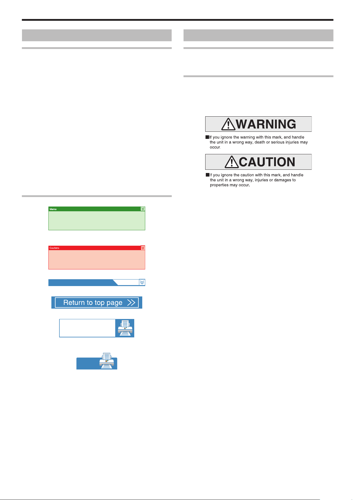
Graphical Symbols
v
A number of graphical symbols are used in this manual as well as on
the printer. They are intended to ensure the safe use of this product,
protect users against safety hazards, as well as prevent damage of
property. Make sure that you read through this manual after gaining
a proper understanding of the symbols’ meaning.
.
.
v
Information in this frame is for reference purposes, such as
information on functions and usage restrictions.
.
v
Precautions are described in this frame.
.
v
Click this frame to display the details page.
.
v
Click this icon to return to the top page.
.
v
Click this icon to open the PDF files for all items.
The “Adobe Reader” application is needed to browse the PDF file.
.
v
Click this icon to open the PDF file for the displayed item.
The “Adobe Reader” application is needed to browse the PDF file.
3
Page 4
Before Use
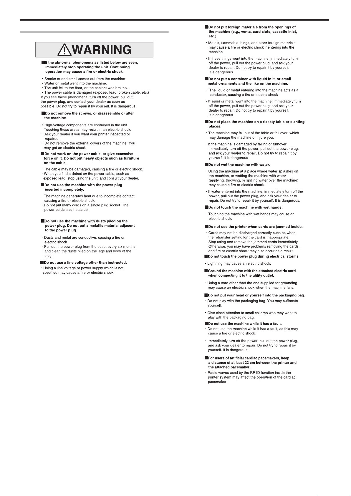
Warnings
.
.
.
4
Page 5
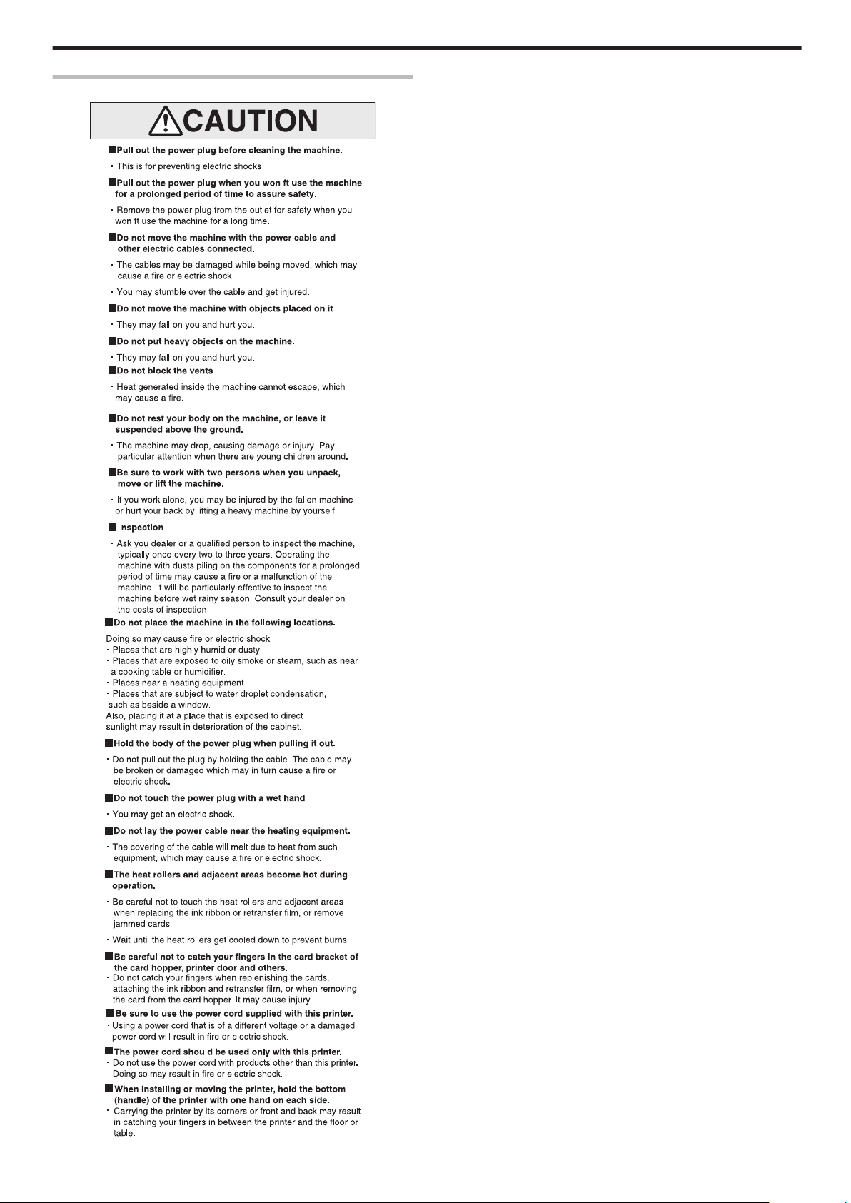
Caution
Before Use
.
.
5
Page 6
Before Use
Precautions During Use
v
Please read through all the following items before using the printer.
Printer Installation
v
When the printer is not in use, it is recommended that you turn off
the power, and use a cover that is large enough to cover up the
entire printer unit.
v
Do not place the printer unit in the following locations. Doing so may
have adverse effects on the printer.
v
Carpeted room.
v
Places with a busy flow of people.
v
Places where paper (corrugated boards, etc.) is handled or stored.
v
Places near photocopiers.
v
Places exposed to direct sunlight or near a heating equipment
(such as a stove).
v
Inclined or unstable surfaces.
v
Places exposed directly to cold air, such as near an air-conditioner
outlet, or places subject to high temperatures.
v
When installing the printer, ensure there is sufficient space around
the printer. (Install the printer by allowing a clearance of at least 20
cm between its sides and surrounding walls. Allow a clearance of at
least 10 cm between the rear of the printer and the wall.)
v
When installing or moving the printer, hold the bottom (handle) of the printer
with one hand on each side to avoid jamming your hands or fingers.
m
Canceling the transport mode
v
While in the transport mode during installation, the retransfer film
cannot be loaded. If the printer is turned on without loading the
retransfer film, a [Film Search] message appears and the transport
mode is canceled.
m
During transport or moving of the printer
v
Make sure to set to the transport mode.
"Transport Mode Setting" (A page 29)
Precautions on Retransfer Film/Ink Ribbon/Card
m
Handling instructions
Pay careful attention of the following when handling a printing media
(retransfer film or ink ribbon) or card.
v
Using a deformed or scratched card may cause card feed errors.
v
Touching the printing surface of the printing media or card directly
with your hand may cause the print to turn out uneven.
v
Foreign particles attached to the printed areas may result in printing
voids. Install the printing media or card in a clean environment.
v
Use of electrically-charged printing media or cards may cause
printing errors. Do not allow static to occur, such as due to cards
rubbing against each other.
v
When replacing or replenishing a printing media or card that is stored
under a low temperature, use after leaving the media or card in the
operating ambient temperature of the printer for at least one hour.
Otherwise, condensation may occur, causing printing errors or
malfunction of the printer.
m
Storage instructions
v
The storage conditions of the printing media (retransfer film or ink
ribbon) and card have a significant effect on the printing quality.
Store the printing media or card in one of the following locations.
m
Storage environment
v
Temperature: 5 °C to 25 °C
v
Relative humidity: 40 % to 60 %
m
Storage location
Do not store the printing media or card in the following locations.
Doing so may cause the media or card to deteriorate.
v
Places exposed to direct sunlight.
v
Places with a high temperature and humidity.
v
Places near organic solvents or diazo copiers.
m
Storage period
v
Use the printing media (retransfer film or ink ribbon) within half a
year after purchase. For details on the cards, please consult our
authorized dealers.
Precautions on Retransfer Film/Ink Ribbon
v
Put on the supplied gloves when handling the retransfer film/ink
ribbon. Direct contact of your hand with the printing surface may
result in printing errors.
m
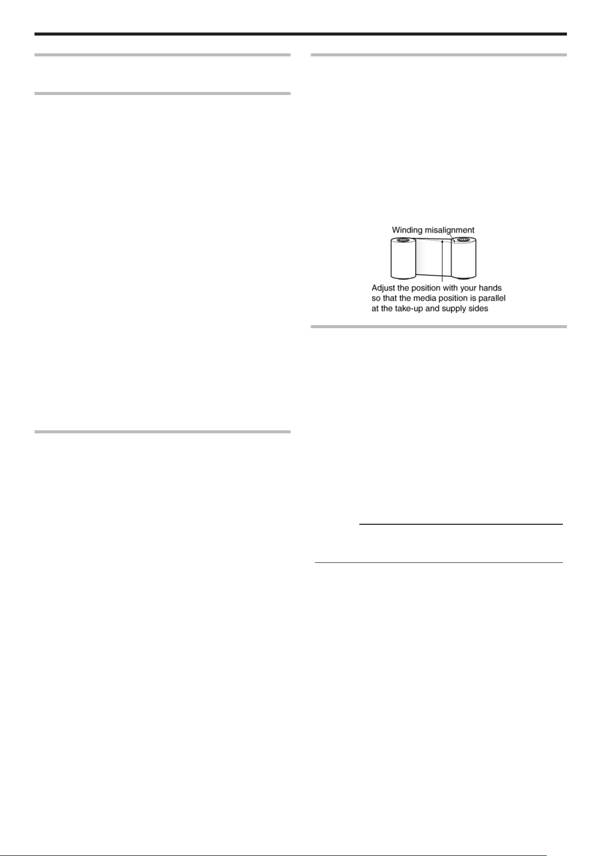
When retransfer film/ink ribbon is dismantled
v
Winding misalignment may occur. If an improperly wound
retransfer film/ink ribbon is loaded, printing failure or error may
occur.
m
When loading the retransfer film/ink ribbon
v
Use your hands to adjust the media at the supply and take-up
sides so that they are parallel to each other.
When doing so, make sure you do not touch the printing surface.
v
Refer to the label adhered to the cassette for alignment of the
image position. Printing errors may occur if the position is not
properly aligned.
.
Precautions on Cards
v
Put on the supplied gloves when handling the cards. Direct contact
of your hand with the printing surface of the card may result in
printing errors.
m
Handling and storage of cards after printing
Avoid storing cards at places that are exposed to direct sunlight or
subject to high temperature and humidity.
Discoloration or fading may occur if a card comes into contact with
the following chemicals or stationery.
v
Organic solvents, including alcohol, film cleaner, and diazo copies.
v
Files, document cases, pass holders, or erasers made of flexible
polyvinyl chloride.
v
Hair wax or cosmetic products.
m
Card types
Thin cards and certain card materials may not be suitable for printing
using this printer. For details on the card material to use and other
specifications, please consult our authorized dealers in advance.
Cautions:
v
If the card thickness is not properly adjusted, printing error or
printer malfunction may occur.
"Adjusting card thickness" (A page 63)
m
When a card is jammed inside the printer
Cards may not be discharged correctly such as when the retransfer
setting for the card is inappropriate.
Stop using and remove the jammed cards immediately. Otherwise,
you may have problems removing the cards, and fire or electric
shock may also occur as a result.
v
When a card is jammed, remove it according to the procedure
described in the Electronic Manual.
v
If the card cannot be removed, do not try to do so forcibly. Consult
our authorized dealers or the servicing personnel.
6
Page 7
Before Use
Disclaimer
.
Name and Functions of Parts
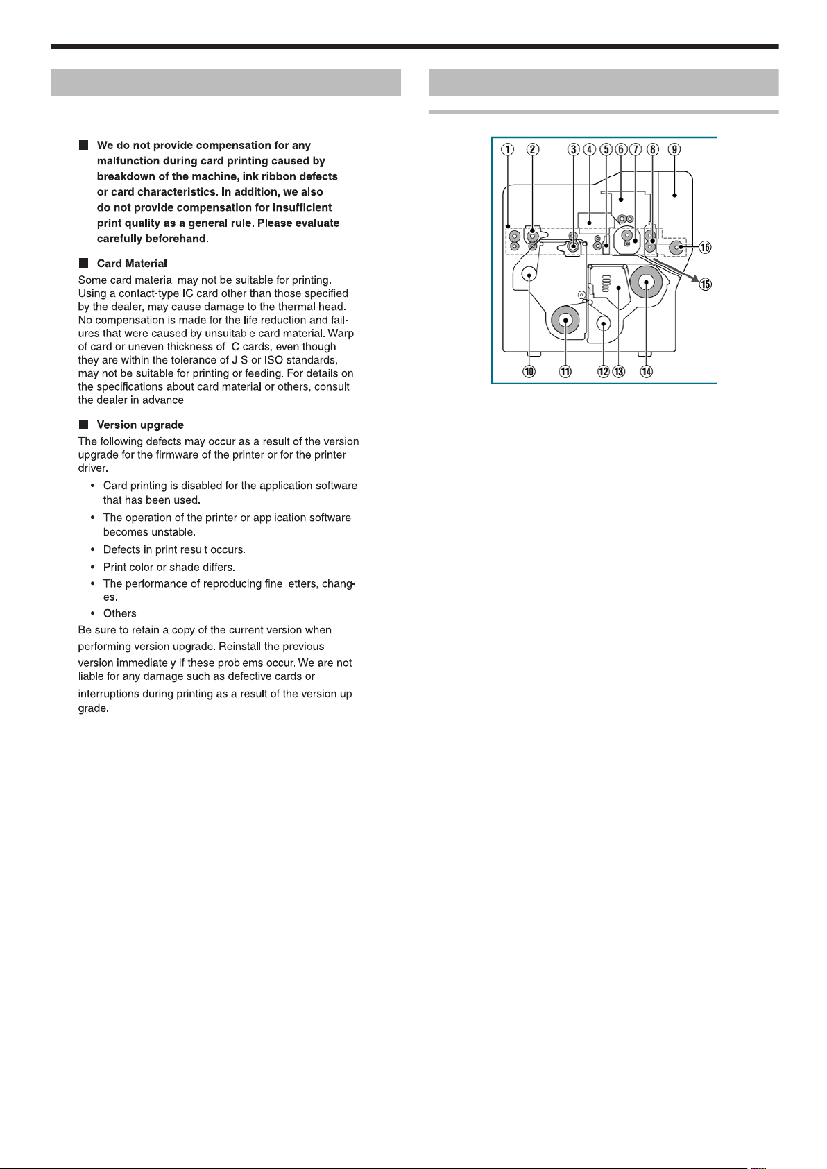
Internal Mechanism Diagram
.
A Card feeder unit
v
This is the roller for feeding cards.
B Bend remedy unit (optional)
v
Corrects bending of the card after retransfer.
C Retransfer heating roller
v
Transfers images printed on the retransfer film to the card.
D Non-contact IC encoder (optional)
v
Writes data to a non-contact IC card.
E Contact section of contact IC encoder (optional)
v
Writes data to a contact IC card.
F Magnetic encoder (optional)
v
Writes data to a magnetic stripe card.
G Card turn over unit (double-sided printer only)
v
Inverts the card.
H Cleaning roller
v
Removes dust or dirt attached to the card.
I Card hopper
v
For loading cards.
J Retransfer film (take-up side)
v
For attaching the take-up side of the retransfer film.
K Retransfer film (supply side)
v
For attaching the unused side of the retransfer film.
L Ink ribbon (take-up side)
v
For attaching the take-up side of the ink ribbon.
M Thermal head
v
Prints images on the retransfer film.
N Ink ribbon (supply side)
v
For attaching the unused side of the ink ribbon.
O NG card outlet
v
Discharges NG cards, such as during card jams.
P Card load roller
v
Roller for loading cards.
7
Page 8
Before Use
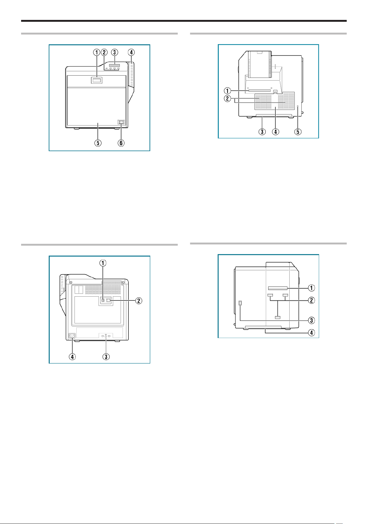
Front
.
A Sliding knob
v
Opens/closes the printer door.
v
Slide it upward, and pull toward you to open the printer door.
B Operation buttons
v
For selecting and confirming information on the operation panel.
C Operation panel
v
Displays the settings, operating status, and error messages.
D Card hopper
v
For loading cards.
E Printer door
F Power switch
v
Turns the power On/Off.
Right
.
A NG card outlet
v
If a card is left inside the printer when the power is turned on or
reset, the card will be automatically discharged.
v
Cards in the printer are discharged when an error occurs in the
magnetic stripe card or IC card.
B Air suction fan opening
v
Air inlet of the internal cooling fan.
C Handle
v
Hold this area when moving the printer.
D Filter cover
v
Cover of the fan filter.
E Security slot
v
An anti-theft device that supports Kensington locks can be
installed.
Rear
.
A USB cable connection terminal
v
For connecting a USB 2.0 interface cable.
B LAN cable connection terminal
v
For connecting a LAN cable.
C Cable clamp
v
For securing the supplied USB cable.
"Connection" (A page 64)
D AC inlet
v
For connecting the power cord.
Left
.
A Card outlet
v
Outlet for discharging the cards.
B Card stacker (supplied) attachment slot
v
For installing the supplied card stacker.
C Infrared window
v
Sends or receives data via infrared communication by connecting
with an external unit.
D Handle
v
Hold this area when moving the printer.
8
Page 9
Before Use
When Printer Door is Open
.
A Card feed roller shaft
v
When a card jam occurs, attach a jog dial to turn the card feed
roller.
B Card turn over unit shaft
v
When a card jam occurs, attach a jog dial to turn the card turn
over unit.
C Cleaning unit
v
Removes dust or dirt attached to the card.
D Cleaning roller shaft
v
When a card jam occurs, attach a jog dial to turn the cleaning
roller.
E Ink ribbon cassette
v
For installing the ink ribbon.
F Jog dials
v
For removing jammed cards by turning it after it is detached from
the printer unit and attached to the shaft.
G Retransfer film cassette
v
For installing the retransfer film.
H Cassette buttons
v
Press these buttons in order to pull out the ink ribbon cassette or
retransfer film cassette.
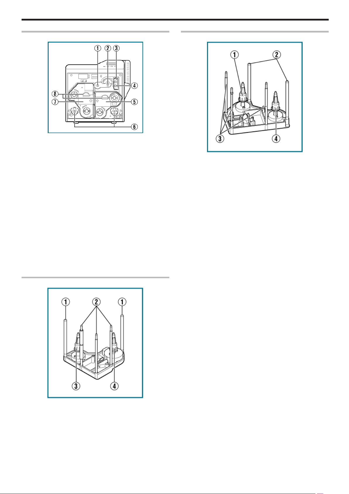
Retransfer Film Cassette
.
A Bobbin holder (black)
v
For securing the take-up side of the retransfer film.
B Guide shaft
v
Provides guide to the position for installing the cassette.
C Shafts
v
For installing the retransfer film.
D Bobbin holder (green)
v
For securing the unused side of the retransfer film.
Ink Ribbon Cassette
.
A Guide shaft
v
Provides guide to the position for installing the cassette.
B Shafts
v
For installing the ink ribbon.
C Bobbin holder (black)
v
For securing the take-up side of the ink ribbon.
D Bobbin holder (yellow)
v
For securing the unused side of the ink ribbon.
9
Page 10
Before Use
Specifications
Main Specifications
Item Description
Recording system Dye sublimation retransfer
Paper feed mode Automatic
Recording density 300 dpi
Reproduction
gradation
Interface
Operating
environment
conditions
Storage
environment
conditions
Power supply AC 100 V - 120 V, 50 Hz/60 Hz
Current
consumption
Power
consumption
Mass approx. 13.5 kg (single-sided printer, including
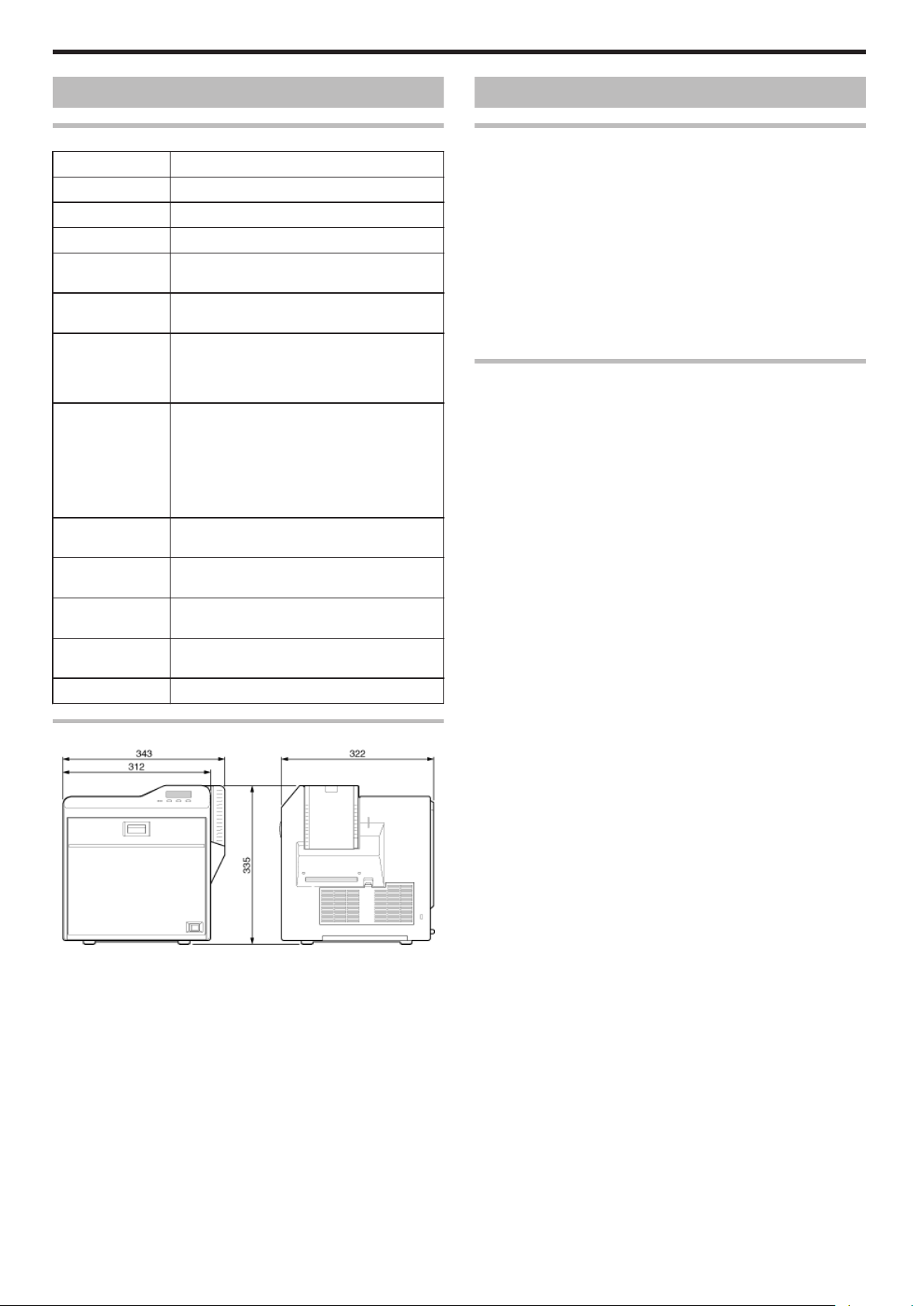
Dimensions 343 mm x 335 mm x 322 mm (W x H x D)
256 levels each for Y, M and C
2 levels for Resin K
USB2.0(Hi-speed/Full Speed)
Ethernet(100BASE-TX/10BASE-T)
Temperature: 15 °C to 30 °C
(When peel-off ink, UV ink is used: 17 °C to 28 °C)
Humidity: 35 % to 70 % No condensation
(When peel-off ink, UV ink is used: 35 % to 60 %)
<Printer unit>
Temperature: -15 °C to 55 °C
Humidity: 20 % to 80 %
<Printing media (retransfer film or ink ribbon) /
card>
Temperature: 5 °C to 25 °C
Humidity: 40 % to 60 %
AC 220 V - 240 V, 50 Hz/60 Hz
3.5 A (100 V system)
1.6 A (200 V system)
310 W (maximum power when all options are
installed)
bend remedy unit)
Accessories/Products Sold Separately
Accessories
Please check to ensure that the printer accessories are in place
when unpacking the product package.
v
CD-ROM x 1
v
Instruction Manual x 1
v
“READ ME FIRST”(LST1004) x 1
v
Power Cord (2 m) x 2
v
Cleaning Card x 1
v
Card Stacker x 1
v
USB 2.0 Cable (2 m) x 1
v
Gloves x 1
v
Tweezers x 1
Products Sold Separately
To purchase these items, please consult our authorized dealers.
Use the retransfer film or ink ribbon within half a year after purchase.
v
YMCK (1000 frames/roll) Set, Model: CY-P340A
Ink Ribbon, Model: CY-340-100
Retransfer Film, Model: CY-3RA-100
v
YMCKP (750 frames/roll) Set, Model: CY-P35PA
Ink Ribbon, Model: CY-35P-75
Retransfer Film, Model: CY-3RA-75
v
Ink Ribbon (YMCKK) 750 frames/roll, Model: CY-35K-75
v
Ink Ribbon (YMCKU) 750 frames/roll, Model: CY-35U-75
v
Retransfer Film 1000 frames/roll, Model: CY-3RA-100
v
Cleaning Kit, Model: CX210-CKIT1
Magnetic Head Cleaning Card (5 Pcs), Cotton Swab (5 Large and
5 Small), Cleaning Wipes (1 Box)
v
Cleaning Card, Model: CX210-CC1
10 Pcs/Set
Outline Dimensional Drawing
.
*The specifications and appearance of this product may be modified
for improvement without prior notice.
10
Page 11

Options
Options
v
Bend remedy unit
Device for correcting card bend after printing.
v
Magnetic encoder
Device for writing data to a magnetic stripe card.
It can only be installed on a double-sided printer.
v
Contact IC encoder
Device for writing data to a contact IC card.
v
Non-contact IC encoder
Device for writing data to a non-contact IC card.
Before Use
11
Page 12
Operating the Printer
Printing a Card
Cautions:
v
If you see an [Initializing..] or [Preheating..] message on the LCD
panel of the printer, this means the printer is not ready yet. Printing
cannot be performed until a [Ready] massage appears.
v
Printing the card on the side with the magnetic stripe may cause
printing errors or damage to the card’s functions. If you want to do
so, please consult our authorized dealers in advance.
v
For printing using application software prepared by the user, refer to
the instruction manual of the corresponding application.
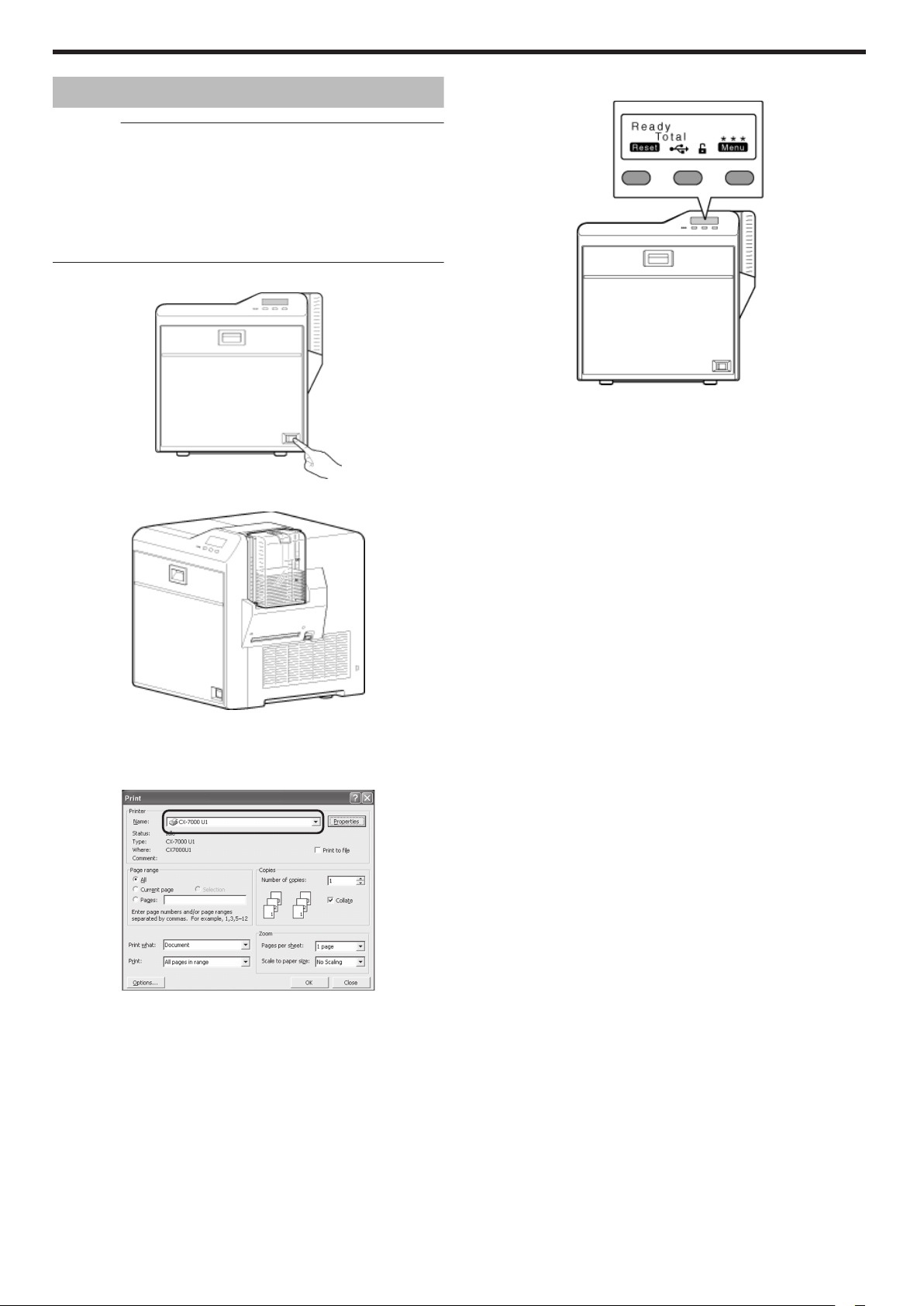
Turn on the power
1
.
Check to ensure that cards are inserted into the card hopper
2
After ensuring that a [Ready] message appears on the LCD panel of
4
the printer, start printing
.
.
Open the application’s print settings screen, and select this printer in
3
[Name]
v
If there are multiple printers, select the name of the printer that you
want to perform printing on.
.
12
Page 13
Ready
Tot al
Reset Menu
***
A
B
C
Reset
Menu
Exit
Enter
Next
Change
Scroll
Operating the Printer
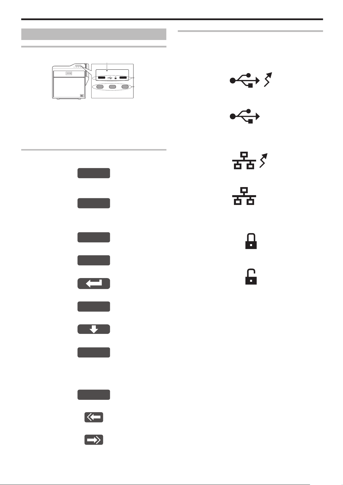
Operation Panel
Name and Functions of Parts
.
A Operation panel
v
Displays the settings, operating status, and error messages.
B Status icon/operation button display
v
Displays the status icon and function of the operation button.
C Operation buttons
v
For selecting a button function displayed on the operation panel.
Operation Buttons
m
Resets the printer.
.
v
Press KNB in sequence.
m
Enters the setting mode.
Icon Displays on the Operation Panel
m
USB connection
v
IP address established
Printer information can be viewed through the network. However,
printing is performed through USB connection.
.
v
IP address not established
.
m
Network connection
v
IP address established
.
v
IP address not established
.
m
Exits setting.
Pressing it each time brings you to the setting item on
the next higher level.
.
m
Displays the setting item on the next lower level.
.
m
Confirms or executes the setting.
.
m
Pressing it each time displays the next setting item.
.
m
Pressing it each time displays the next setting.
.
m
Enters the settings change mode.
.
v
If F is not displayed for an item, you can adjust the settings on
the status monitor of a computer.
"Status Monitor Settings" (A page 107)
m
Enters the scroll mode for the displayed characters.
m
Security lock status
v
Locked
v
Unlocked
.
.
.
m
m
.
Scrolls to the next displayed character on the left.
.
Scrolls to the next displayed character on the right.
.
13
Page 14
Boot Up..
Initializing..
Preheating..
Ready
Moving..
Printing..
Testing..
Loading..
Downloading..
MG Encoding..
IC Encoding..
Heating..
Retransfer..
Cleaning..
Sleeping..
Operating the Printer
Operation Panel Operation Display
Background color
Changes according to the printer’s operating status.
v
During startup
Bright green
v
Under normal circumstances
Sky blue
v
During initialization using K, during test printing using the
operation panel, cleaning, downloading and during security lock
setting using the operation panel
Light purple
v
During error
Red
m
Starting up
.
m
Initializing
m
Downloading
.
m
Magnetic encoding in progress
.
m
IC encoding
.
m
Adjusting heating roller to the preset temperature
.
m
Retransferring
.
m
Preheating
.
m
Ready
.
m
Feeding card or discharging NG card
.
m
Printing
.
m
Test print in progress
m
Cleaning
m
Power Saving mode
.
.
.
m
Loading card
14
.
.
Page 15

Operating the Printer
Setting Mode
v
Settings can be viewed on the printer’s operation panel.
v
Settings can be changed on the status monitor of the computer.
"Setting Using the Operation Panel" (A page 22)
"Sequence of Setting Modes" (A page 17)
"Factory Settings" (A page 19)
Cleaning
v
For setting during cleaning of the card feed roller, heating roller or
magnetic head.
"Card Feed Roller/Heating Roller" (A page 37)
"Magnetic Head" (A page 39)
Settings
v
Rollers
Select this value when cleaning the card feed roller or heating roller.
v
MG
Select this value when cleaning the magnetic head.
Counter Reset
v
This is used to reset the free counter and error counter.
"Counter Reset" (A page 26)
Test Print
v
Prints the printer’s built-in test pattern, or the different settings.
"Test Print" (A page 23)
Settings
v
Test Print: Test Pattern, Printer Setting, Network Setting, Lami
Setting
Download
v
Updates the firmware.
"Firmware Update" (A page 24)
Transport Mode
v
For setting the transport mode.
"Transport Mode Setting" (A page 29)
Media
v
Displays the settings of the printing media.
Settings
v
Ink Type: YMCK, YMCKPO, YMCKK, YMCKUV
Displays the ink ribbon type.
v
Film Type: 1000, 750
Set according to the type of retransfer film.
v
Card Thickness: Standard, Thin
Set according to the thickness of the card.
Standard: Supports card thickness of 0.76 mm
Thin: Supports card thickness of 0.25 mm
Print
v
Displays the printing settings.
Settings
v
YMC Level: -3, -2, -1, 0, 1, 2, 3
For setting the YMC (color) density level.
Selecting a larger value increases the density level.
v
Black Level: -3, -2, -1, 0, 1, 2, 3
For setting the K (black) density level.
Selecting a larger value increases the density level.
v
Black Mode: Standard, Fine
For setting the printing mode for the K (black) component.
If the characters still appear faded after raising the [Black Level], set
to [Fine]. However, printing time required will be longer than the
[Standard] setting.
v
UV Level: -3, -2, -1, 0, 1, 2, 3
For setting the UV ink density level.
Selecting a larger value increases the density level.
During UV printing, card bend may increase if the card has a low
heat resistance or in an environment with high temperature.
v
PO Level: -3, -2, -1, 0, 1, 2, 3
For setting the density level of the peel-off ink.
Selecting a larger value increases the density level.
Retransfer
v
Displays the retransfer mode settings.
Settings
v
Temp Level: -2, -1, 0, 1, 2
For setting the retransfer heating roller temperature.
Selecting a larger value increases the temperature.
Retransfer may fail depending on the card used. If retransfer fails, raise
the setting to the next higher value.
A higher retransfer heating roller temperature helps to enhance the card
retransfer performance, but the stronger heat may cause the card to
deform more.
If the printer is not reset after changing the temperature setting,
temperature is adjusted after the printing operation starts.
v
Speed (Front): -3, -2, -1, 0, 1, 2
For setting the front side retransfer speed.
Selecting a larger value increases the speed.
Retransfer may not be successful on some parts of the card depending on
the card used. Lowering the setting value helps to enhance the retransfer
performance, but the stronger heat may cause the card to deform more.
v
Speed (F-UV): -3, -2, -1, 0, 1, 2
For setting the retransfer speed of the second panel on the front side during
UV ink printing of retransfer films in two panels. Selecting a larger value
increases the speed.
v
Speed (Back): -3, -2, -1, 0, 1, 2
For setting the back side retransfer speed.
Selecting a larger value increases the speed.
Some types of cards may bend during double-sided printing. If card bend
occurs, raise the back side retransfer speed to one level higher than the
front side retransfer speed setting.
v
Speed (B-UV): -3, -2, -1, 0, 1, 2
For setting the retransfer speed of the second panel on the back side during
UV ink printing of retransfer films in two panels. Selecting a larger value
increases the speed.
v
MG Peel Mode: Standard, MG Stripe
For setting the method for peeling the retransfer film.
Retransfer at areas close to the magnetic stripe may not be performed
correctly for some card types. When a magnetic stripe card is used, this
problem may be remedied by setting to [MG Stripe].
v
Standby Mode: Front wait, Back wait
During double-sided printing by connecting to a laminator, retransfer
remains in the standby state until the laminator is in the [Ready] mode.
Select whether to standby using the front or back side.
v
Backside Cool: On, Off
For setting the time interval for cooling the card before performing
retransfer on the back side during double-sided printing. Setting this to
[On] may help to reduce card bend.
15
Page 16
Operating the Printer
Bend Remedy
v
Displays the bend remedy mode settings.
Settings
v
Temp Level: -5, -4, -3, -2, -1, 0, Off
For setting the bend remedy heating roller temperature.
Selecting a larger value increases the temperature.
If the printer is not reset after changing the temperature setting,
temperature is adjusted after the printing operation starts.
v
Speed: -2, -1, 0, 1, 2
For setting the bend remedy speed.
Selecting a larger value increases the speed.
Heat Roller
v
Displays the settings of the Power Saving mode or HR Control
mode.
Settings
v
Power Saving: 5, 10, 15, 20, 25, 30, 45, 60, Off (unit: mins)
For setting the time for the Power Saving mode.
While in the [Ready] mode, if the printer is not operated for a specific
time interval, the retransfer heating roller, bend remedy heating
roller, and backlight of the operation panel will turn off automatically
to save power.
While in the Power Saving mode, [Sleeping..] is displayed.
To cancel the setting temporarily using the operation panel, press
KNB to reset the printer.
v
HR Control: Off, On
For setting whether to standby the printer by lowering the retransfer
heating roller temperature if cards are not printed for 30 minutes or
longer.
The printer will automatically be restored to the original mode during
the next card printing, but it may take a longer time before the first
card is printed. Set this to [On] during normal use.
Option
v
Displays the optional settings.
Settings
v
MG: None, ISO
Displays the availability of a magnetic encoder or the type of
magnetic encoder used.
v
IC Antenna: None, Installed
Displays the availability of a non-contact IC encoder.
v
IC Contact: None, ISO Type
Displays the availability of a contact IC encoder (contact section) or
the type of IC encoder used.
v
Contact IC R/W: None, Installed
Displays the availability of a contact IC R/W.
v
Bend Remedy HR: None, Installed
Displays the availability of a bend remedy unit.
v
Turn Over: None, Installed
Displays the availability of a card turn over unit.
MG
v
Displays the magnetic encoder settings.
Settings
v
ISO Type: Loco, Hico
For setting the coercivity when writing data to an ISO magnetic stripe
card.
v
Retry Count: 0, 1, 2, 3
For setting the maximum number of retries when writing to or
reading of the magnetic stripe fails.
Network
v
Displays the network settings.
Setting
v
Displays the printer settings.
v
Setting can also be performed using the printer’s operation panel.
Settings
v
Display:
Mode: Counter, Laminator State
This is used for setting the information to be displayed on the
operation panel.
"Display Mode Setting" (A page 25)
Counter: Total Cnt, Head Cnt, Free Cnt, Cleaning Cnt, Error Cnt
This is used for setting the type of counter displayed on the
operation panel.
"Counter Setting" (A page 25)
Contrast: -3, -2, -1, 0, 1, 2, 3
For setting the contrast of the operation panel display.
"Contrast Setting" (A page 27)
v
Buzzer: On, Off
For setting whether to sound the buzzer when an error occurs or
when settings are changed.
"Buzzer Setting" (A page 28)
v
Unit No.:No.1 - No.10
For setting the printer’s unit number according to the USB
environment.
"Unit Number Setting" (A page 28)
Settings
v
Printer Name: ASCII character strings (10 characters)
For setting the printer name.
v
Host IF: LAN, USB
For setting the interface.
If the printer is connected via USB interface, the setting switches
automatically to USB when initialization starts even if the LAN setting
is selected.
v
IPv4:
DHCP: On, Off
Setting: IP Address, Subnet Mask, Gateway
Efective IP:IP Address
For setting IPv4.
v
IPv6:
Adrs Config: Auto, Manual
Setting: IP Address, Prefix Len, Gateway
Efective IP: IP Address1, IP Address2, IP Address3
For setting IPv6.
v
Session Time Out: Off, 10 mins, 20 mins, 30 mins, 60 mins
For setting the session timeout interval.
v
MAC Address: Hexadecimal character strings
Displays the MAC address.
v
IPSec Mode: Off, On
For setting the availability of IPSec.
v
IPSec Type: not Setting, Preshard, Certificate
Displays the method of IPSec authentication.
16
Page 17
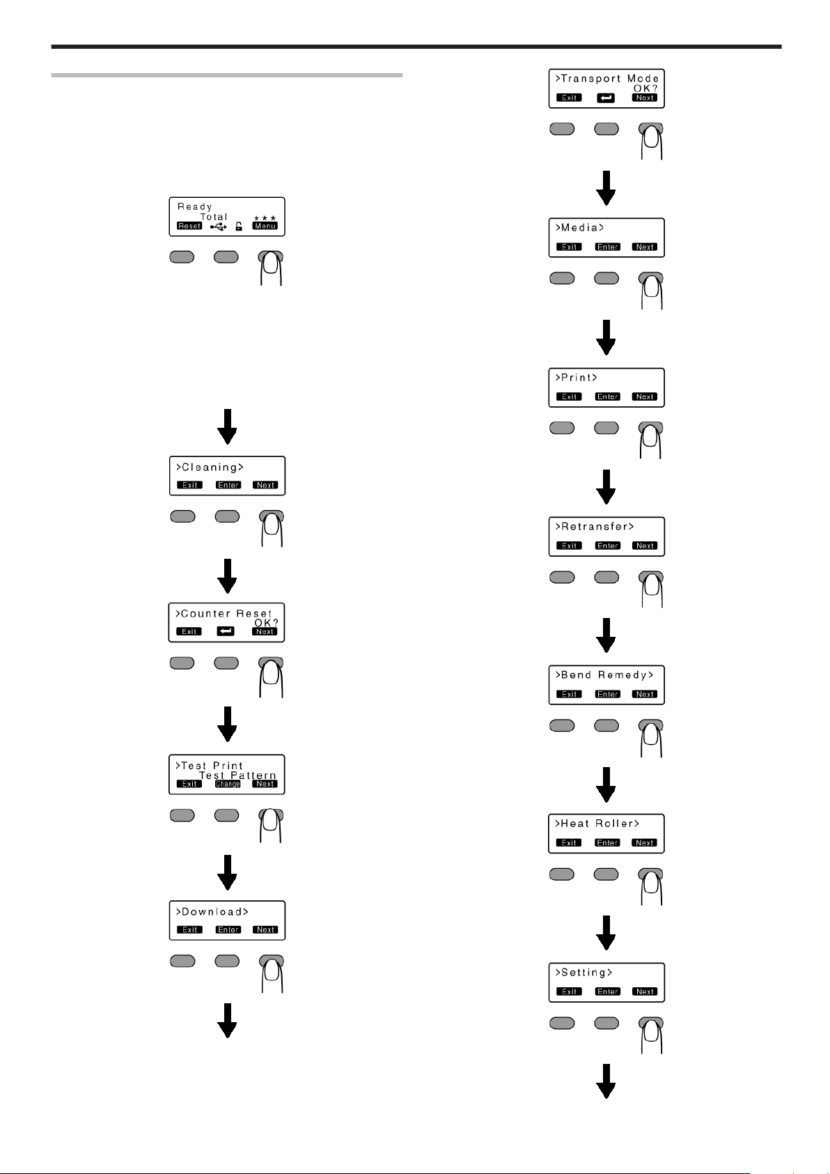
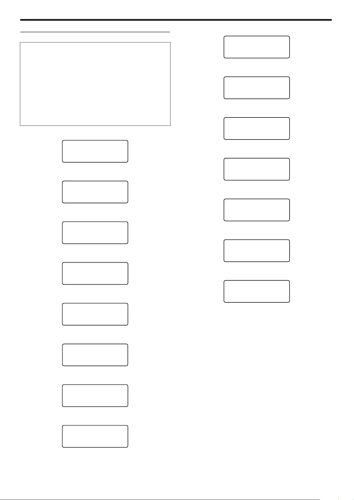
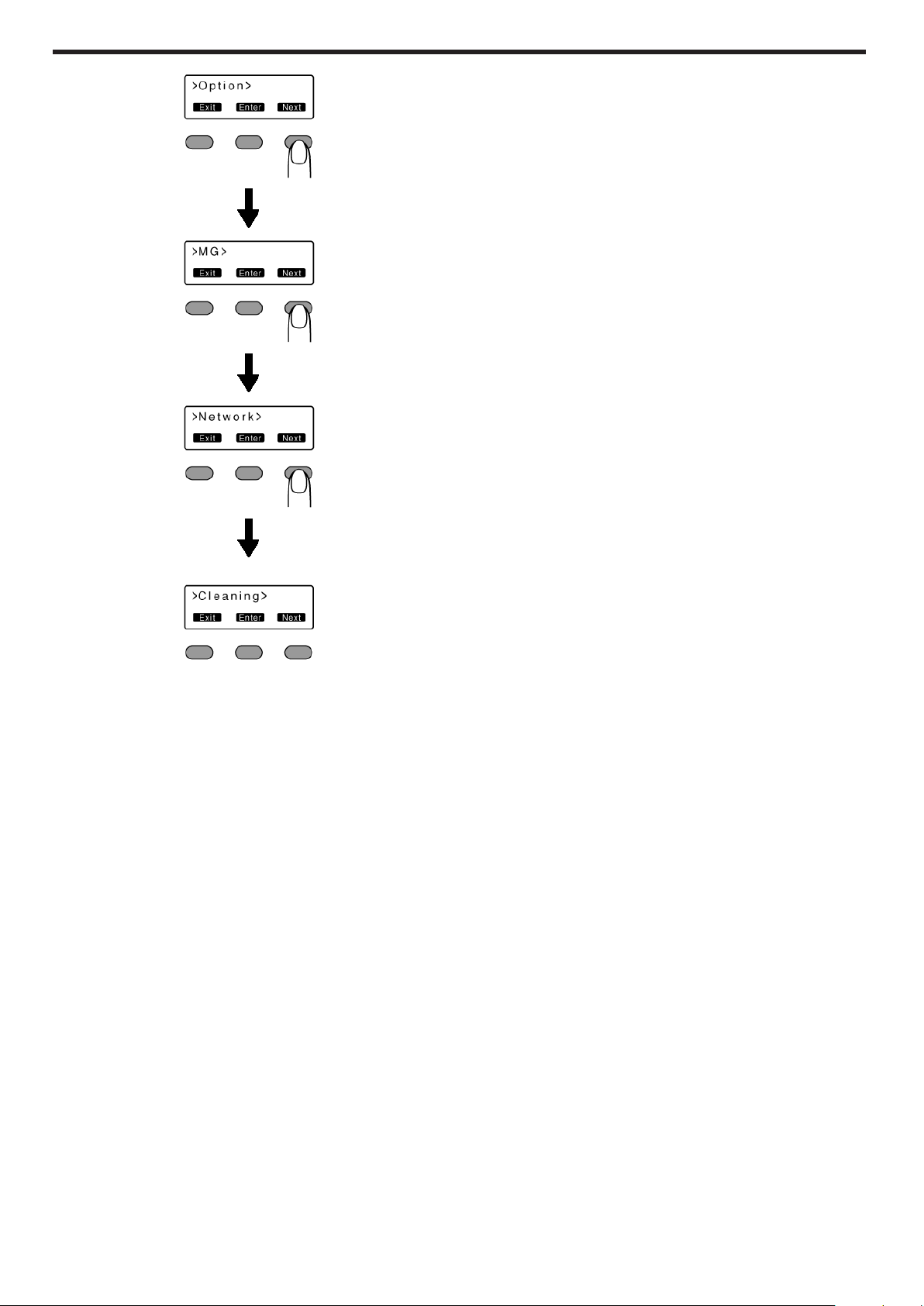
Sequence of Setting Modes
v
Settings can be viewed on the printer’s operation panel.
v
Settings can be changed on the status monitor of the computer.
"Setting mode" (A page 15)
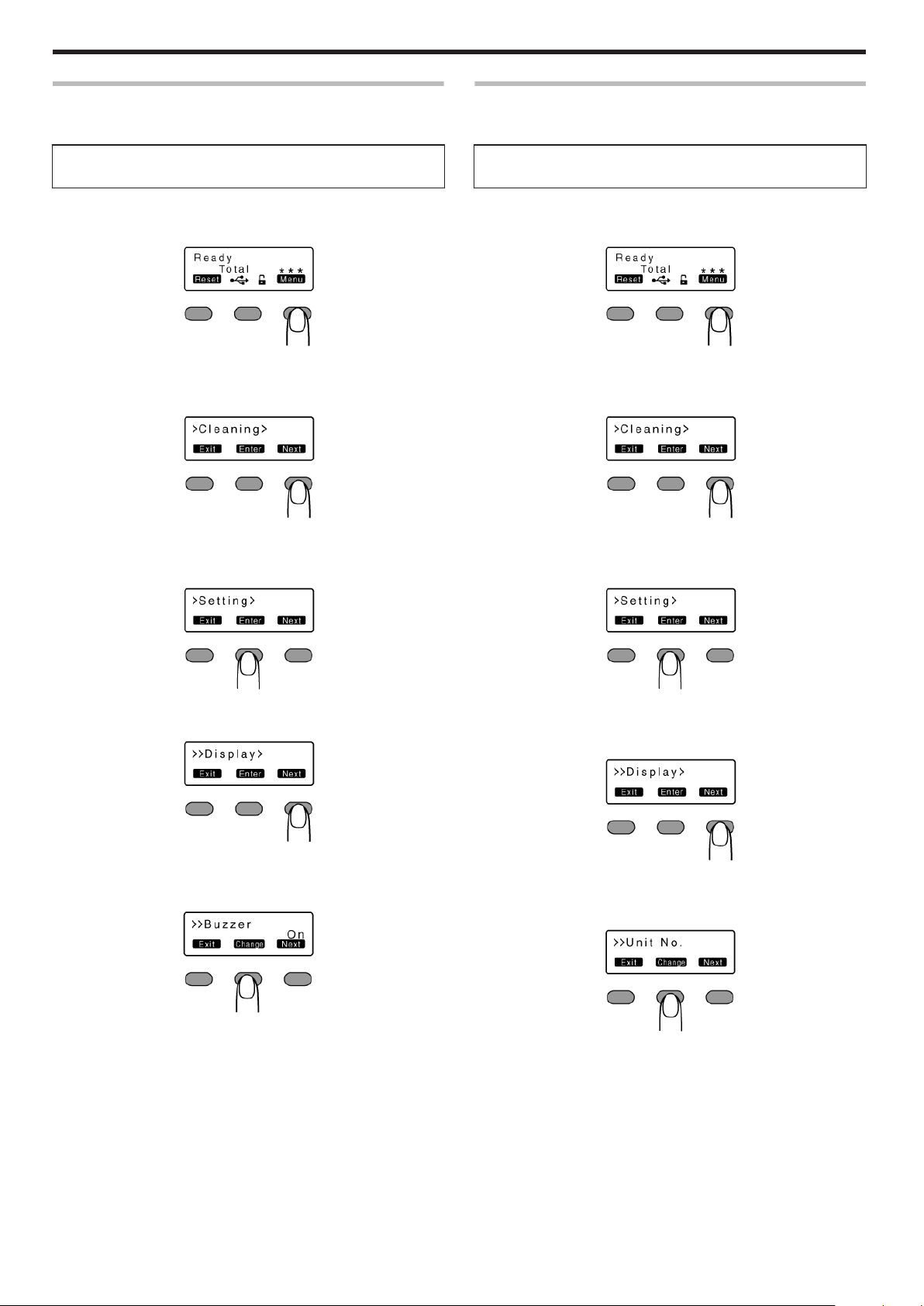
1
Press I
v
Enters the setting mode.
.
2
Press J
v
Pressing it each time displays the next setting item.
v
Pressing G displays the setting item on the next lower level.
v
Pressing F enters the settings change mode.
v
Pressing B confirms or executes the setting.
v
Pressing H displays the setting item on the next higher level.
Operating the Printer
.
.
.
.
.
.
.
.
.
.
.
.
.
.
.
.
.
.
.
.
.
.
.
17
Page 18
Operating the Printer
.
.
.
.
.
.
.
18
Page 19
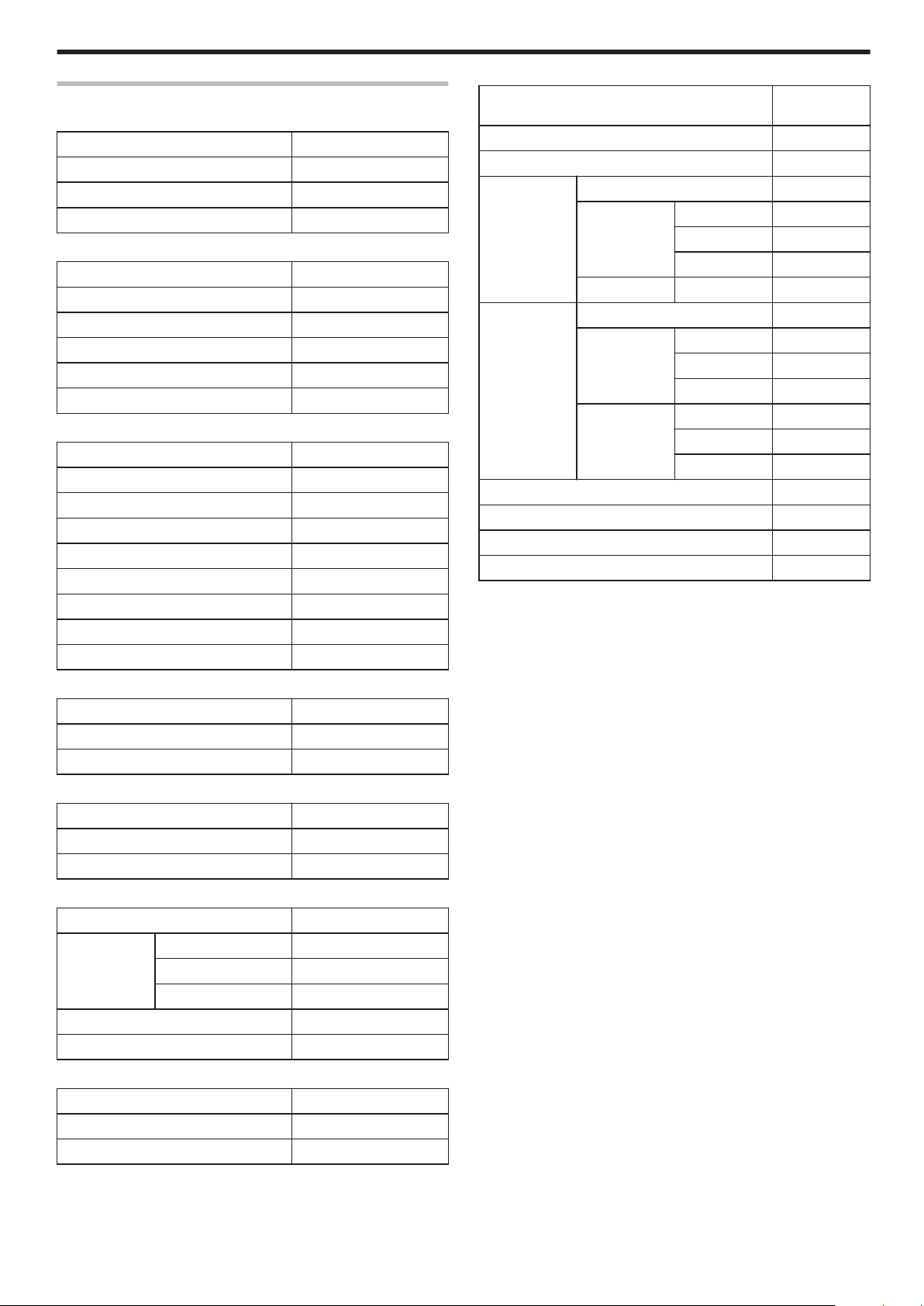
Factory Settings
m
Media
Item Factory Settings
Ink Type -
Film Type 1000
Card Thickness Standard
m
Print
Item Factory Settings
YMC Level 0
Black Level 0
Black Mode Standard
UV Level 3
PO Level 0
m
Retransfer
Item Factory Settings
Temp Level 1
Speed (Front) 2
Speed (F-UV) 2
Speed (Back) 2
Speed (B-UV) 2
MG Peel Mode Standard
Standby Mode Front Wait
Backside Cool Off
Operating the Printer
m
Network
Item Factory
Printer Name PRINTER01
Host IF LAN
IPv4 DHCP On
Setting IP Address 192.168.0.141
Subnet Mask 255.255.255.0
Gateway 192.168.0.1
Effective IP IP Address -
IPv6 Adrs Config Auto
Setting IP Address None
Prefix Len 64
Gateway None
Effective IP IP Address 1 -
IP Address 2 -
IP Address 3 -
Session Time Out Off
Mac Address -
IPSec Mode Off
IPSec Type not Setting
Settings
m
Bend Remedy
Item
Temp Level Off
Speed 2
m
Heat Roller
Item
Power Saving Off
HR Control On
m
Setting
Item
Display Mode Counter
Counter Total Cnt
Contrast 0
Buzzer On
Unit No. No.1
m
MG
Item
ISO Type Hico
Retry Count 1
Factory Settings
Factory Settings
Factory Settings
Factory Settings
19
Page 20
Operating the Printer
Security Lock
v
The security lock function can be applied to the printer door and card
hopper to prevent opening of the printer door as well as removal of
cards.
v
The lock can be turned on/off using the status monitor on the
computer.
"Status monitor" (A page 117)
v
By registering a security key number on the printer unit, you can turn
off the security lock by entering the security key number on the
operation panel of the printer.
v
If you forgot the security key number, please consult our authorized
dealer or the servicing personnel.
Registration of Security Key Number
v
To change the security key number, you have to delete it and
register a new number again.
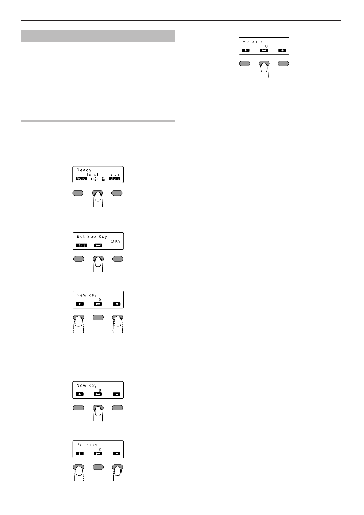
Press the operation button (center) for at least three seconds
1
v
A [Set Sec-Key OK?] message appears.
6
Press B
.
v
If this number is consistent with the number entered in [New key],
the display returns to [Ready], and the security key number is
registered.
v
If this number is not consistent with the number entered in [New
key], the display returns to [Set Sec-Key OK?]. Enter a number
again.
.
2
Press B
v
A [New key] message appears.
.
Enter a number
3
.
v
You can enter up to 8 digits.
v
Pressing A each time advances to the next number.
v
Pressing E each time advances to the next digit.
4
Press B
v
A [Re-enter] message appears.
.
Input the number you have entered in [New key] again
5
.
20
Page 21
Operating the Printer
Deactivating the Security Lock
v
When a security lock is turned on, you can deactivate it as follows.
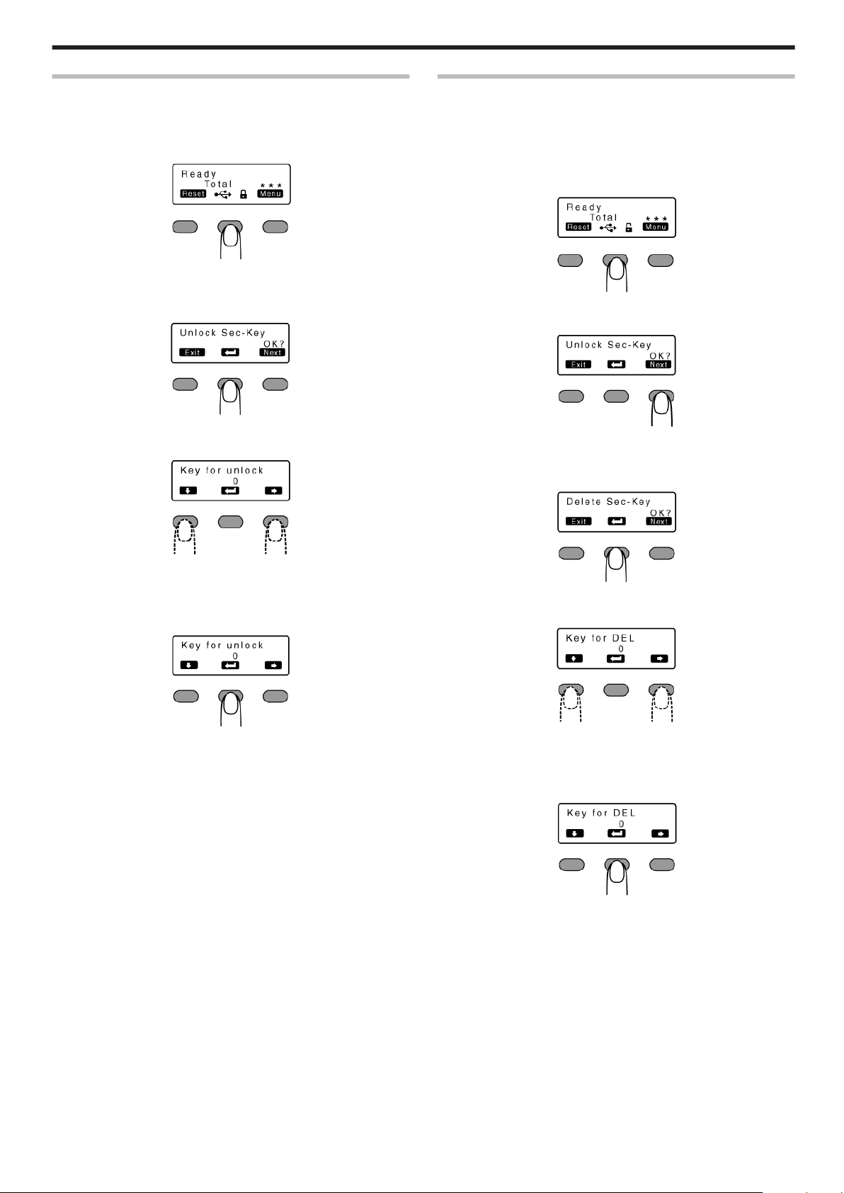
Press the operation button (center) for at least three seconds
1
v
A [Unlock Sec-Key OK?] message appears.
.
2
Press B
v
A [Key for unlock] message appears.
.
Enter the registered security key number
3
Deleting the Security Key Number
v
You can delete a registered security key number as follows.
v
To change the security key number, you have to delete it and
register a new number again.
Press the operation button (center) for at least three seconds
1
v
A [Unlock Sec-Key OK?] message appears.
.
2
Press J to set to [Delete Sec-Key OK?]
.
3
Press B
v
A [Key for DEL] message appears.
.
v
Pressing A each time advances to the next number.
v
Pressing E each time advances to the next digit.
4
Press B
.
v
If this number is consistent with the registered number, the display
returns to [Ready], and the security lock is deactivated.
v
If this number is not consistent with the registered number, the
display returns to [Unlock Sec-Key OK?]. Enter a number again.
.
Enter the registered security key number
4
.
v
Pressing A each time advances to the next number.
v
Pressing E each time advances to the next digit.
5
Press B
.
v
If this number is consistent with the registered number, the display
returns to [Ready], and the security key number is deleted.
v
If this number is not consistent with the registered number, the
display returns to [Delete Sec-Key OK?]. Enter a number again.
21
Page 22
Operating the Printer
Setting Using the Operation Panel
Initialization
v
Whenever the power is turned on, cue (initialization) is performed
automatically on the ink ribbon and retransfer film.
v
You can also perform initialization manually using the operation
button on the operation panel.
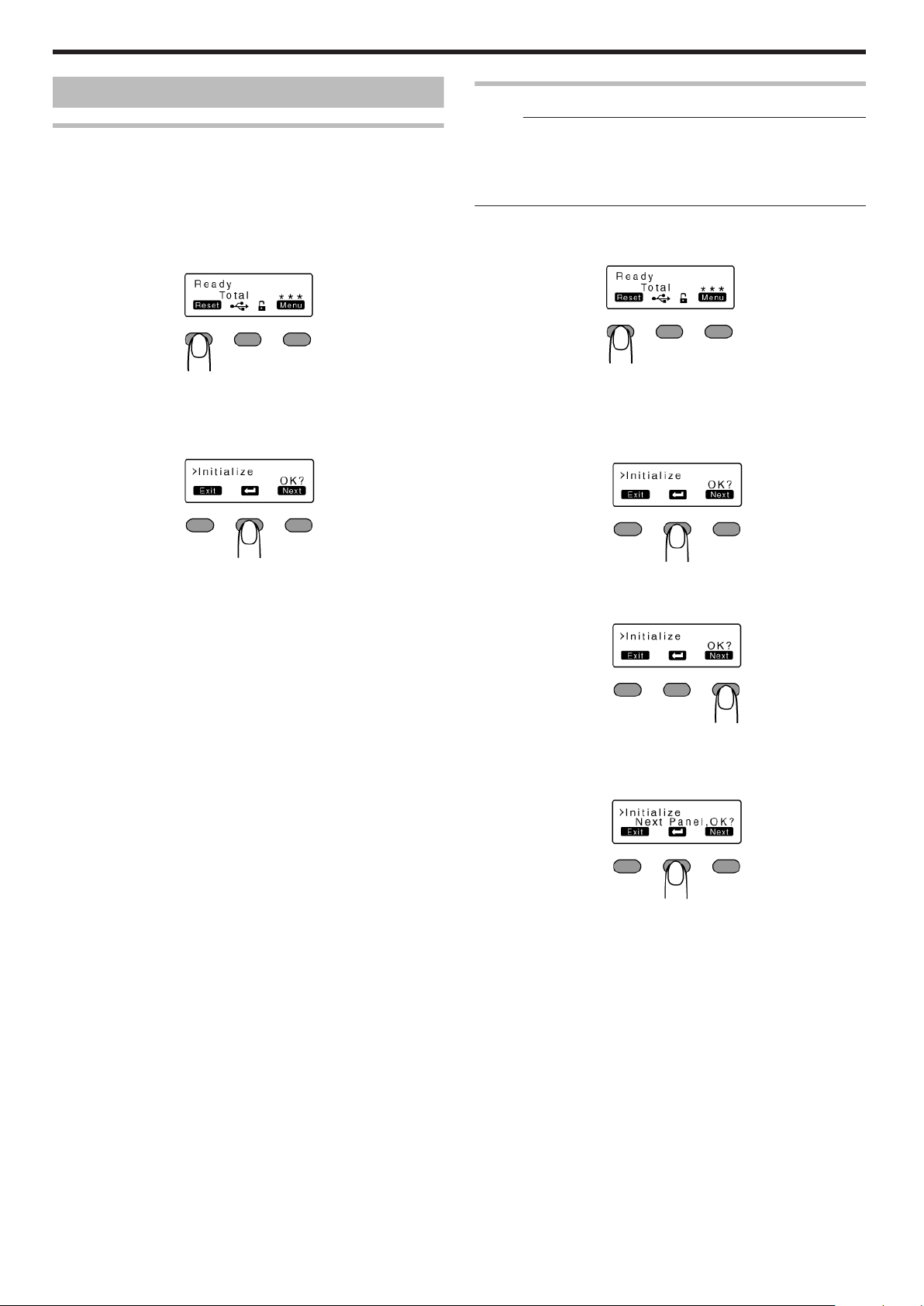
1
Press K
v
An [Initialize OK?] message appears.
.
2
Press B
v
An [Initializing..] message appears, and initialization of the printer
starts.
Initializing Printer When Installing the Cassette
Memo:
v
When detaching the ink ribbon cassette or retransfer film cassette
from the printer body, dust may adhere to the ink ribbon or retransfer
film. Errors such as discoloring may occur depending on the size of
the dust particles. To avoid these problems, it is recommended that
you forward by one or two images after installing the cassette.
1
Press K
v
An [Initialize OK?] message appears.
.
m
Initializing printer without feeding the image
A Press B
v
An [Initializing..] message appears, and initialization of the
printer starts.
.
m
Initializing printer after feeding by one image
.
A Press J to set to [Next Panel, OK?]
.
B Press B
v
An [Initializing..] message appears, and the printer is initialized
after feeding the ink ribbon and retransfer film by one image.
.
22
Page 23
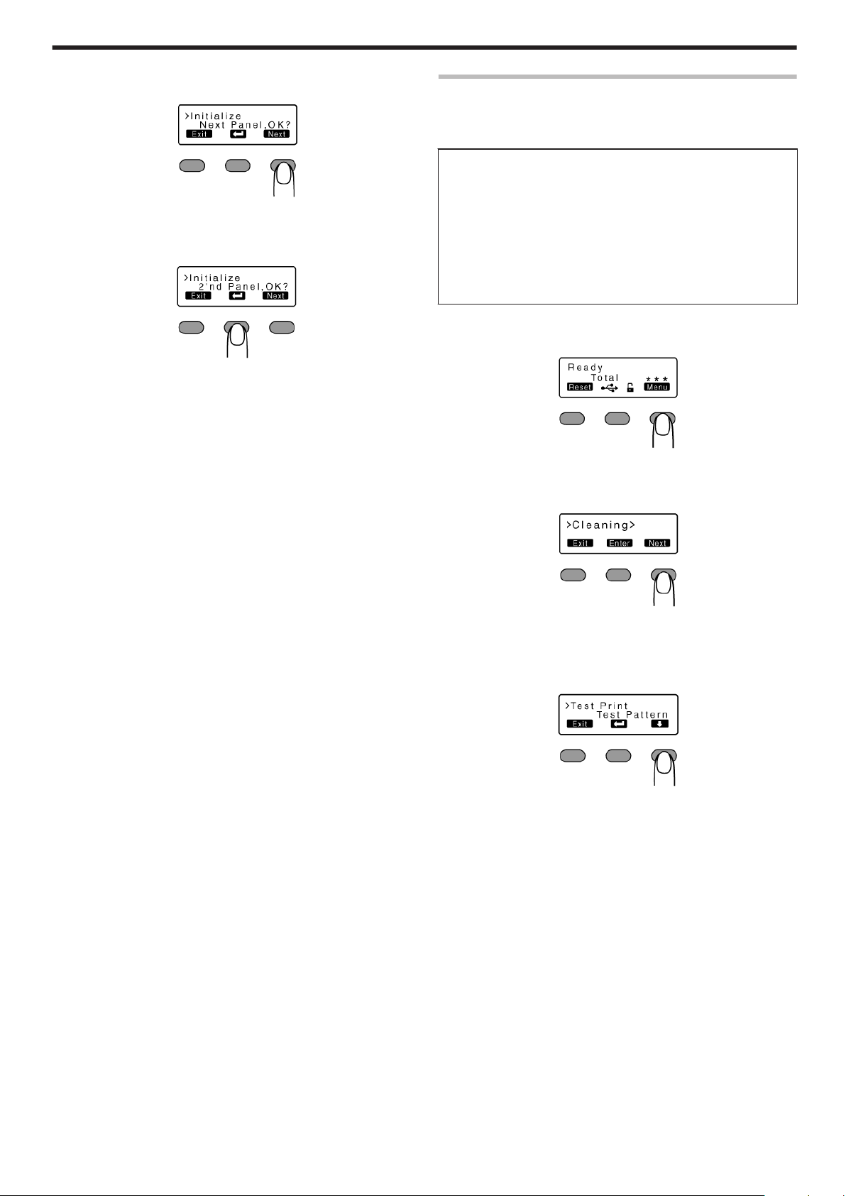
m
Initializing printer after feeding by two images
A Press J to set to [2'nd Panel, OK?]
.
B Press B
v
An [Initializing..] message appears, and the printer is initialized
after feeding the ink ribbon and retransfer film by two images.
.
Operating the Printer
Test Print
v
Prints the printer’s built-in test pattern, or the different settings.
v
The printer unit can be made to run alone when a system error
occurs by separating the computer from the printer.
Test Pattern Types
v
Test Pattern:
Prints standard color pattern on a single side of a card.
v
Printer Setting:
Prints the printer settings.
v
Network Setting:
Prints the network settings.
v
Lami Setting:
Prints the laminator settings.
1
Press I
v
A [Cleaning] message appears.
.
2
Press J to set to [Test Print]
v
Pressing it each time displays the next setting item.
.
3
Press F
v
A test pattern selection screen appears.
4
Press A and select a test pattern type
.
5
Press B
v
Test print starts.
23
Page 24
Operating the Printer
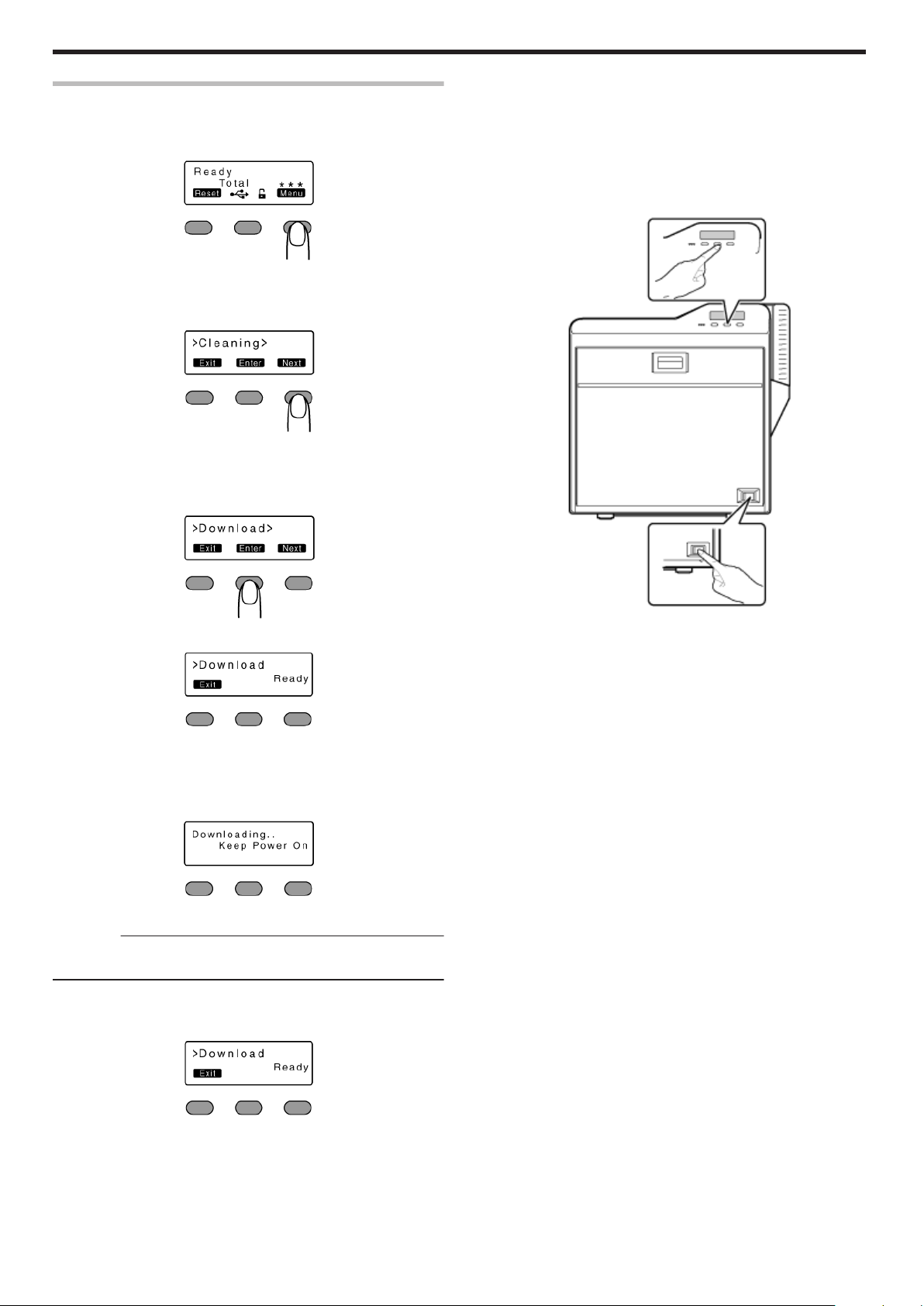
Firmware Update
1
Press I
v
A [Cleaning] message appears.
.
2
Press J to set to [Download]
v
Pressing it each time displays the next setting item.
.
3
Press G
v
A [Download Ready] message appears, indicating that the printer is
ready to download data from the computer.
m
If download fails and printer cannot be started up
v
If download of the printer firmware fails, the printer may not be
able to start up when it is rebooted. When this occurs, download
the firmware again according the following procedure.
A Turn on the power while holding down the operation button
(center)
v
A [SBP2 Running] message appears, indicating that the printer
is ready to download data from the computer.
.
.
Start data download from the computer
4
v
A [Downloading..] message appears.
.
Cautions:
v
Do not turn off the power during data download from the computer.
Doing so may damage the printer firmware and cause malfunction.
v
A [Download Ready] message appears when data download from
the computer is complete.
.
B Start data download from the computer
v
A [Downloading..] message appears.
v
A [SBP2 Running] message appears when data download from
the computer is complete.
C When the [SBP2 Running] message appears, turn off the power
v
The firmware is updated after the power is turned on again.
.
5
When [Download Ready] appears, press H
When the [Please Power Off] message appears, turn off the power
6
v
The firmware is updated after the power is turned on again.
24
Page 25
Operating the Printer
Display Mode Setting
v
This is used for setting the information to be displayed on the
operation panel.
Settings
v
Counter:
Displays the counter preset in "Counter setting".
v
Laminator State:
Displays the operating status of the connected laminator. If a
laminator is not connected, the counter is displayed.
1
Press I
v
A [Cleaning] message appears.
.
2
Press J to set to [Setting]
v
Pressing it each time displays the next setting item.
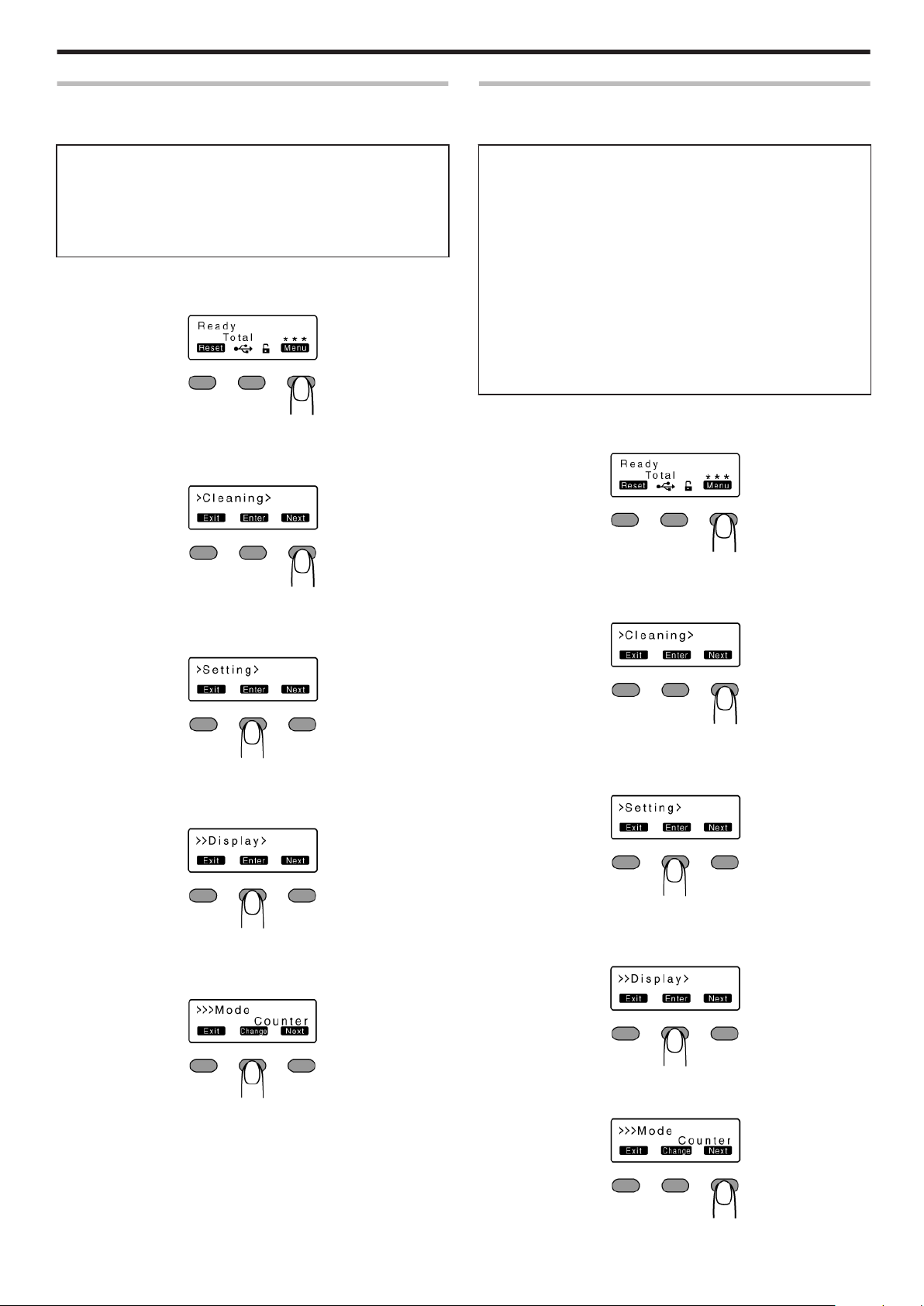
Counter Setting
v
This is used for setting the type of counter displayed on the
operation panel.
Counter Types
v
Total Cnt: total counter
Displays the total number of cards that are correctly printed.
v
Head Cnt: head counter
Displays the total number of printed sides for the same head.
v
Free Cnt: free counter
Displays the number of cards that are correctly printed. This number
can be reset.
v
Cleaning Cnt: cleaning counter
Displays the number of cards that are correctly printed after the last
cleaning.
v
Error Cnt: error counter
Displays the number of cards that are not correctly printed. This
number can be reset.
1
Press I
v
A [Cleaning] message appears.
.
3
Press G
v
A [Display] message appears.
.
4
Press G
v
A [Mode] message appears.
.
5
Press F
v
Enters the settings change mode.
.
2
Press J to set to [Setting]
v
Pressing it each time displays the next setting item.
.
3
Press G
v
A [Display] message appears.
.
4
Press G
v
A [Mode] message appears.
.
6
Press A and select a setting
7
Press B to confirm the setting
v
Pressing B confirms the setting and returns you to the previous
screen.
8
Press H to exit the setting mode
v
Pressing it each time displays the setting item on the next higher level.
.
5
Press J to set to [Counter]
.
25
Page 26
Operating the Printer
6
Press F
v
Enters the settings change mode.
.
7
Press A and select a setting
8
Press B to confirm the setting
v
Pressing B confirms the setting and returns you to the previous
screen.
9
Press H to exit the setting mode
v
Pressing it each time displays the setting item on the next higher
level.
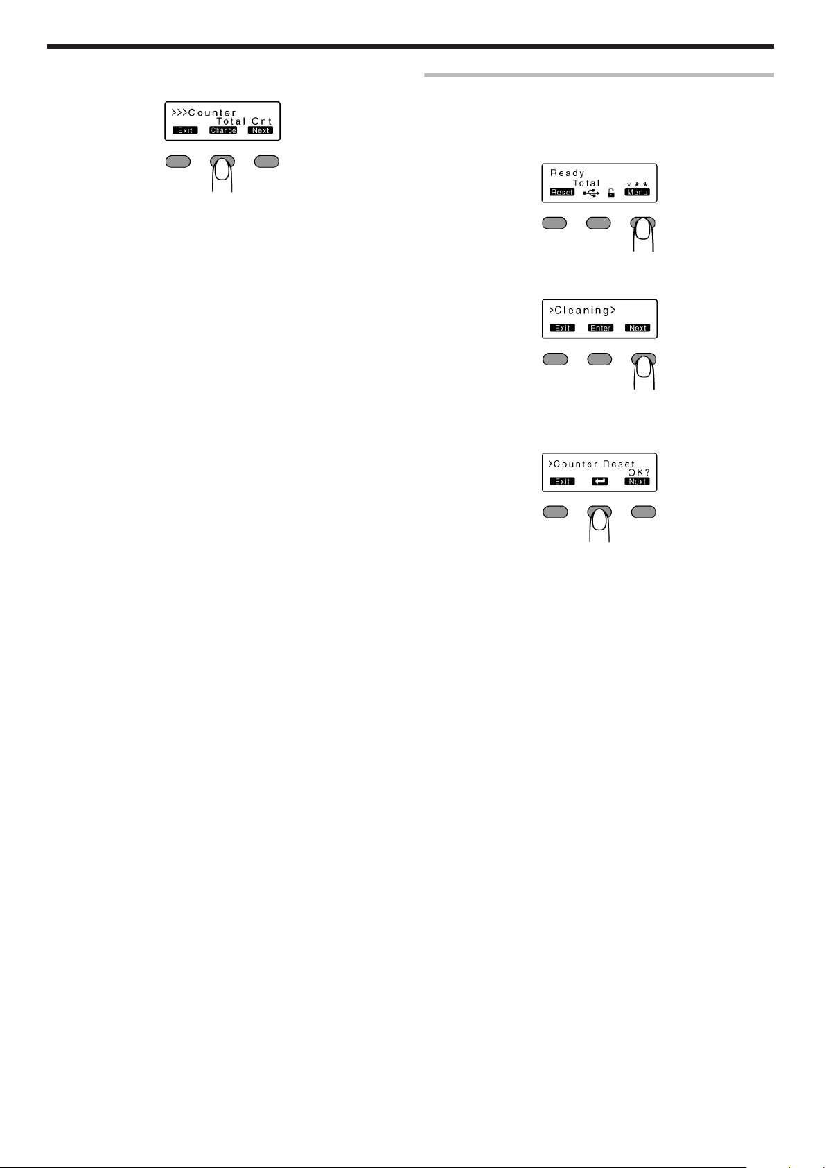
Counter Reset
v
This is used to reset the free counter and error counter.
1
Press I
v
A [Cleaning] message appears.
.
2
Press J to set to [Counter Reset]
.
3
Press B
v
Resets the free counter and error counter.
.
m
Checking reset
v
Select [Free Cnt] or [Error Cnt] for "Counter setting".
26
Page 27
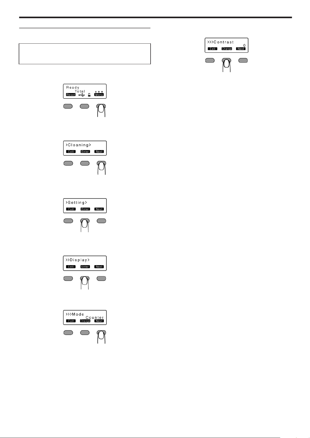
Contrast Setting
v
For setting the contrast of the operation panel display.
Settings
v
-3, -2, -1, 0, 1, 2, 3
Selecting a larger value increases the contrast.
1
Press I
v
A [Cleaning] message appears.
.
2
Press J to set to [Setting]
v
Pressing it each time displays the next setting item.
Operating the Printer
6
Press F
v
Enters the settings change mode.
.
7
Press A and select a setting
8
Press B to confirm the setting
v
Pressing B confirms the setting and returns you to the previous
screen.
9
Press H to exit the setting mode
v
Pressing it each time displays the setting item on the next higher
level.
.
3
Press G
v
A [Display] message appears.
.
4
Press G
v
A [Mode] message appears.
.
5
Press J to set to [Contrast]
v
Pressing it each time displays the next setting item.
.
27
Page 28
Operating the Printer
Buzzer Setting
v
For setting whether to sound the buzzer when an error occurs or
when settings are changed.
Settings
v
On: turns on buzzer sound, Off: turns off buzzer sound
1
Press I
v
A [Cleaning] message appears.
.
2
Press J to set to [Setting]
v
Pressing it each time displays the next setting item.
.
3
Press G
v
A [Display] message appears.
Unit Number Setting
v
For setting the printer’s unit number according to the USB
environment.
Settings
v
No.1 - No.10
1
Press I
v
A [Cleaning] message appears.
.
2
Press J to set to [Setting]
v
Pressing it each time displays the next setting item.
.
3
Press G
v
A [Display] message appears.
.
4
Press J to set to [Buzzer]
.
5
Press F
v
Enters the settings change mode.
.
6
Press A and select a setting
7
Press B to confirm the setting
v
Pressing B confirms the setting and returns you to the previous
screen.
8
Press H to exit the setting mode
v
Pressing it each time displays the setting item on the next higher
level.
.
4
Press J to set to [Unit No.]
v
Pressing it each time displays the next setting item.
.
5
Press F
v
Enters the settings change mode.
.
6
Press A and select a setting
v
You can select the unit number from No. 1 to No. 10.
7
Press B to confirm the setting
v
Pressing B confirms the setting and returns you to the previous screen.
8
Press H to exit the setting mode
v
Pressing it each time displays the setting item on the next higher level.
Turn off the power
9
v
The changes to the setting will be reflected when you turn on the
power again.
28
Page 29
Transport Mode Setting
v
When transporting or moving the printer, ensure that the heating
roller is fastened to a safe position.
Cautions:
v
Make sure that you set to the transport mode when transporting or
moving the printer. Failure to do so will cause the printer to malfunction.
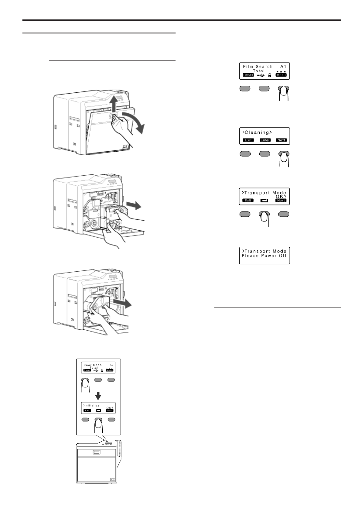
Open the printer door
1
.
Press and hold down the cassette button, and remove the ink ribbon
2
cassette (on the right) to remove the ink ribbon
Operating the Printer
Check to ensure that [Film Search] is displayed on the operation
6
panel of the printer
7
Press I
v
A [Cleaning] message appears.
.
8
Press J to set to [Transport Mode]
v
Pressing it each time displays the next setting item.
.
9
Press B
.
Press and hold down the cassette button, and remove the retransfer
3
film cassette (on the left) to remove the retransfer film
.
Close the printer door
4
5
Press KNB to reset the printer
.
.
v
After setting to the transport mode, a [Please Power Off] message
appears.
Turn off the power, and install the cassette
10
Cautions:
v
While in the transport mode, the retransfer film cassette cannot be
installed to the printer with the retransfer film loaded.
m
Canceling the transport mode
v
With the printer door closed, turn on the power to cancel the
transport mode.
.
29
Page 30

Operating the Printer
Setting Using the Status Monitor
"Status Monitor Settings" (A page 107)
30
Page 31
Cards
Cards have Run Out
v
Replenish the cards.
v
The card hopper is able to store up to about 100 cards with a
thickness of 0.76 mm.
Cautions:
v
Get ready cards that are designated by the authorized dealer.
v
If the security lock is on, deactivate it. After work is complete,
activate the security lock again.
v
Do not touch the printing surface of the card. Touching it may cause
printing errors. Put on the supplied gloves when handling the cards.
v
To prevent card jams from occurring, limit the number of cards
stored in the card hopper at any time to about 100 pieces regardless
of the card thickness.
v
When using new cards, set them after making sure that they are not
adhered to each other due to static.
v
Align the cards before setting them in the printer. Otherwise, the card
hopper cover may not close properly, and this may damage the
printer.
v
Printing the card on the side with the magnetic stripe may cause
printing errors or damage to the card’s functions. If you want to do
so, please consult our authorized dealers in advance.
v
To set cards with both functions (magnetic stripe and contact IC),
follow the procedure for setting the contact IC card.
Replacement
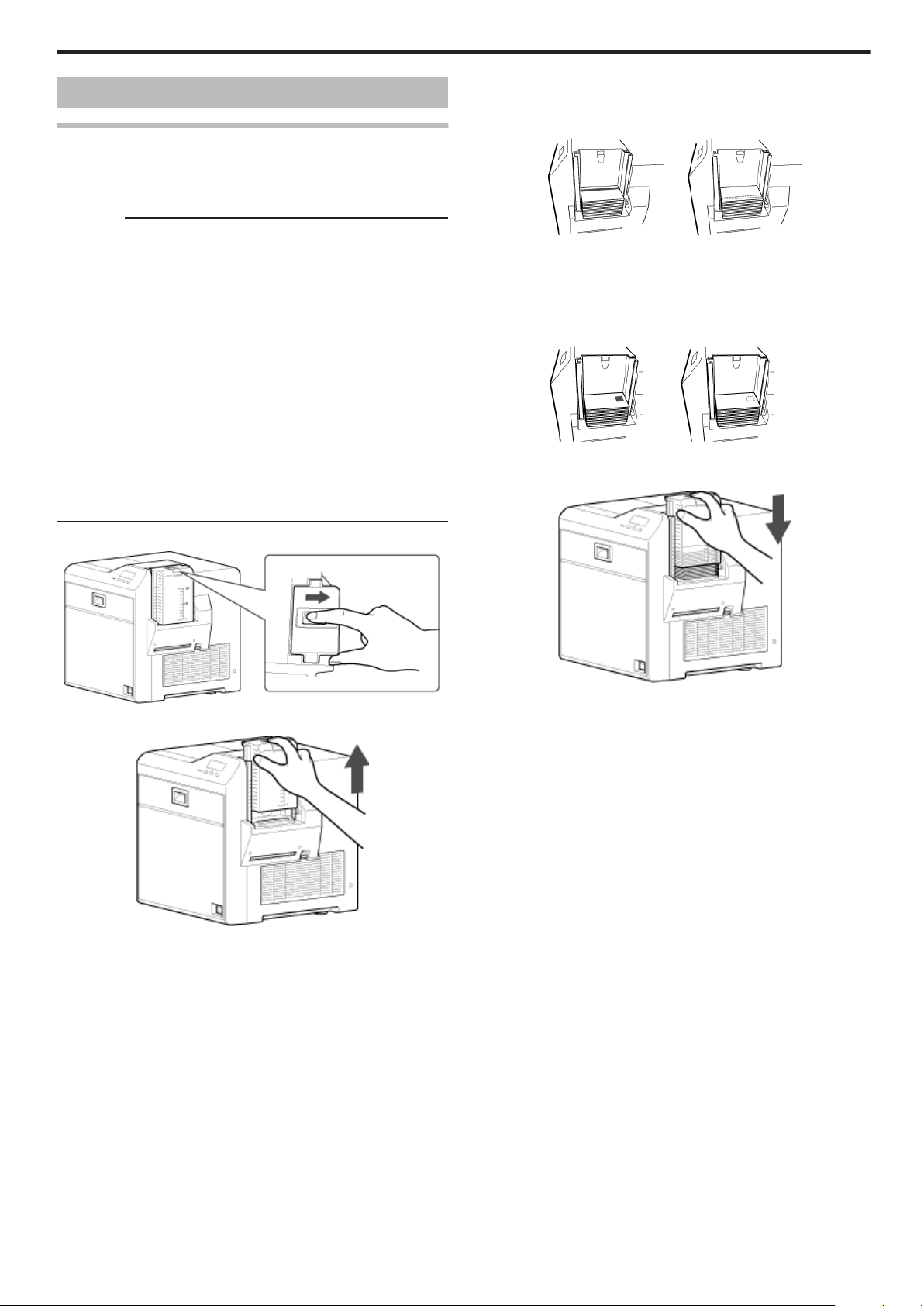
Align the orientation of the cards, and set them in the printer
3
m
Magnetic stripe cards
v
Set the card with the magnetic stripe facing upward and toward
the printer, or facing downward and toward you.
.
m
ISO contact IC cards
v
Set the card with the Contact IC terminal facing upward and
toward the rear of the printer, or downward and toward the rear of
the printer.
v
For single-sided printers, set the cards with the IC terminal facing
down and toward the rear of the printer.
.
Install the card hopper cover, and set the card hopper knob to
4
[LOCK]
Set the card hopper knob to [OPEN]
1
.
Lift to remove the card hopper cover
2
.
.
31
Page 32

Replacement
Ink Ribbon
Ink Ribbon has Run Out
v
Replace with a new ink ribbon.
Cautions:
v
If the security lock is on, deactivate it. After work is complete,
activate the security lock again.
v
Stand the cassette on a flat surface as illustrated in the diagram.
Avoid doing so on the floor as dust attached to it may cause printing
errors.
.
v
Do not touch the inked surface (the side that faces outward when
installed) with your hand. Touching it may cause printing errors. Put
on the supplied gloves when handling the ink ribbon.
v
When installing a used ink ribbon, align the yellow side of the unused
ribbon with the arrow indicated on the label of the cassette. If the
position of the yellow side is not properly aligned, the print may turn
out light.
v
The cassette is heavy when the ink ribbon is loaded. To prevent the
cassette from dropping during handling, make sure to hold it with
both hands.
v
Do not perform any work on the printer door. Do not place heavy
objects or apply load on the printer. Doing so may damage it.
v
During replacement, clean the four bobbin holders on the printer. If
burrs produced by friction with the bobbins are attached to the
bobbin holders, they may fall onto the card, ink ribbon, or retransfer
film, causing printing errors.
"Cleaning the bobbin holders" (A page 40)
Open the printer door
1
With the inked surface facing outward, align the yellow side of the
A
unused ribbon with the arrow on the cassette, and unwind it
along the three shafts.
B Insert the ink ribbon firmly into the bobbin holders with the ribbon
set to the far end of the guides.
v
A: take-up side (black)
v
B: unused side (yellow)
.
Remove any slack in the ink ribbon
4
A Hold the cassette.
B Turn the knob in the direction indicated by the arrow.
.
Insert the cassette all the way in along the guide rail until a “click”
5
sound is heard, followed by closing the printer door
.
Press and hold down the cassette button, and pull out the ink ribbon
2
cassette (on the right) to remove the ink ribbon
.
Install a new ink ribbon
3
v
Install while referring to the indication on the label of the cassette.
.
.
32
.
Page 33

6
Press KNB to reset the printer
.
Memo:
v
To avoid printing errors, it is recommended that you forward by one
or two images after installing the ink ribbon cassette or retransfer film
cassette.
"Initializing printer when installing the cassette" (A page 22)
Replacement
Retransfer Film
Retransfer Film has Run Out
v
Replace with a new retransfer film.
Cautions:
v
If the security lock is on, deactivate it. After work is complete,
activate the security lock again.
v
Stand the cassette on a flat surface as illustrated in the diagram.
Avoid doing so on the floor as dust attached to it may cause printing
errors.
.
v
Do not touch the retransfer face (the side that faces outward when
installed) with your hand. Touching it may cause printing errors. Put
on the supplied gloves when handling the retransfer film.
v
The cassette is heavy when the retransfer film is loaded. To prevent
the cassette from dropping during handling, make sure to hold it with
both hands.
v
When installing a used retransfer film, align the unused side of the
film with the arrow indicated on the label of the cassette. Improper
alignment may result in errors, or the print may turn out light.
v
When installing a new film, make sure that at least three black lines
are wound onto the take-up side. Insufficient winding may cause the
printer to malfunction.
v
Do not perform any work on the printer door. Do not place heavy
objects or apply load on the printer. Doing so may damage it.
v
During replacement, clean the four bobbin holders on the printer. If
burrs produced by friction with the bobbins are attached to the
bobbin holders, they may fall onto the card, ink ribbon, or retransfer
film, causing printing errors.
"Cleaning the bobbin holders" (A page 40)
Open the printer door
1
.
Press and hold down the cassette button, and pull out the retransfer
2
film cassette (on the left) to remove the retransfer film
.
33
Page 34

Replacement
Install a new retransfer film
3
v
Install while referring to the indication on the label of the cassette.
A When installing the retransfer film, make sure that at least three
black lines are wound onto the take-up side.
.
B With the retransfer face facing outward, align the unused side of
the film with the arrow on the cassette, and unwind it along the
three shafts.
C Insert the retransfer film firmly into the bobbin holders with the film
set to the far end of the guides.
v
A: take-up side (black)
v
B: unused side (green)
.
Remove any slack in the film
4
A Hold the retransfer film cassette.
B Turn the knob in the direction indicated by the arrow.
6
Press KNB to reset the printer
.
Memo:
v
To avoid printing errors, it is recommended that you forward by one
or two images after installing the ink ribbon cassette or retransfer film
cassette.
"Initializing printer when installing the cassette" (A page 22)
.
Insert the cassette all the way in along the guide rail until a “click”
5
sound is heard, followed by closing the printer door
.
.
34
Page 35

Servicing of Parts
m
Request for routine servicing
v
In order to prevent printing errors and malfunctions from occurring
in advance, please request for routine servicing by the servicing
personnel. For details on servicing, please consult our authorized
dealers.
Cleaning Roller
v
The function of the cleaning roller is to remove any dirt or dust
attached to the card.
v
The color of the printed card may appear faded or dirt may appear
conspicuous if the cleaning roller is dirty. Card jams may also occur
as a result.
Cautions:
v
If the security lock is on, deactivate it. After work is complete,
activate the security lock again.
v
Start work after ensuring that the power has been turned off.
v
If the printer is used every day, make sure to clean the cleaning
roller daily at the end of the operation.
v
Do not perform any work on the printer door. Do not place heavy
objects or apply load on the printer. Doing so may damage it.
v
After washing, allow the cleaning roller to dry completely before
installing it to the printer.
v
Do not wash the cleaning roller with anything other than water (e.g.,
alcohol).
v
Replace the cleaning unit with a new one after using it for about one
year. For details on its replacement, please consult our authorized
dealers.
v
After cleaning is complete, check to ensure that all dismantled parts
are restored to their original positions. Failure to restore the parts
may result in malfunction of the printer.
Maintenance
Wash the cleaning roller with water
3
v
Wash the roller with water, and remove any dirt from the surface of
the cleaning roller with your finger.
.
Allow the cleaning roller to air dry
4
Open the printer door
1
.
Remove the cleaning unit
2
.
.
Set the cleaning unit, and close the printer door
5
v
With the roller facing the right, insert it all the way in.
.
35
Page 36

Maintenance
Card Load Roller
v
Card jams may occur if the card load roller is dirty.
Cautions:
v
If the security lock is on, deactivate it. After work is complete,
activate the security lock again.
v
Start work after ensuring that the power has been turned off.
v
After cleaning is complete, check to ensure that all dismantled parts
are restored to their original positions. Failure to restore the parts
may result in malfunction of the printer.
v
For details on separately sold items, please consult our authorized
dealers.
Remove the card hopper
1
.
Apply alcohol (sold separately) to a wiper (sold separately), and use
2
it to wipe the surface of the card load roller
v
Wipe while turning the card load roller in the anti-clockwise direction.
Fan Filter
v
The color of the printed card may appear faded or dirt may appear
conspicuous if the fan filter is dirty.
v
Perform cleaning after printing about 10,000 cards.
Cautions:
v
Start work after ensuring that the power has been turned off.
v
After cleaning is complete, check to ensure that all dismantled parts
are restored to their original positions. Failure to restore the parts
may result in malfunction of the printer.
v
Replace the fan filter with a new one after using it for about one year.
For details on its replacement, please consult our authorized dealers.
Remove the filter cover located on the side of the printer
1
.
Remove the fan filter
2
.
Install the card hopper
3
.
.
Remove any dirt that is attached to the fan filter using a vacuum cleaner
3
v
Hold the filter with your hand to prevent it from being sucked into the
vacuum cleaner.
.
Set the fan filter
4
.
Set the filter cover
5
36
.
Page 37
Card Feed Roller/Heating Roller
v
The color of the printed card may appear faded or dirt may appear
conspicuous if the card feed roller or heating roller is dirty.
v
Perform cleaning after printing about 1,000 cards.
Cautions:
v
If the security lock is on, deactivate it. After work is complete,
activate the security lock again.
v
Before cleaning the card feed roller and heating roller, make sure
that you clean the cleaning roller. Otherwise, dirt on the cleaning
roller may be attached to the cleaning card, causing its cleaning
capability to deteriorate.
v
Stand the cassette on a flat surface as illustrated in the diagram.
Avoid doing so on the floor as dust attached to it may cause printing
errors.
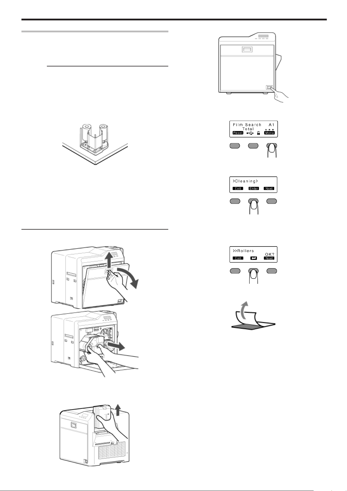
Turn on the power
4
.
5
Press I to set to [Cleaning]
Maintenance
.
v
If card jam occurs when the cleaning card is inserted, turn off and on
the power of the printer. Doing so automatically discharges the card.
v
Do not perform any work on the printer door. Do not place heavy
objects or apply load on the printer. Doing so may damage it.
v
Each cleaning card can only be used once. Reusing a dirty card may
dirty the roller or cause the printer to malfunction.
v
After cleaning is complete, check to ensure that all dismantled parts
are restored to their original positions. Failure to restore the parts
may result in malfunction of the printer.
v
For details on separately sold items, please consult our authorized dealers.
Open the printer door. Press and hold down the cassette button,
1
and remove the retransfer film cassette (on the left)
.
.
6
Press G to set to [Rollers]
.
7
Press B
v
A [Film Checking..] message appears, followed by a [Cleaning Start
OK?] message.
.
Peel off the backing paper from the cleaning card (sold separately)
8
.
Close the printer door
2
Remove the card hopper
3
.
.
37
Page 38

Maintenance
9
Press B
v
A [Cleaning..] message appears.
.
Cautions:
v
If the retransfer heating roller is hot, a [HR is too hot!] message will
be displayed. Turn off the power, and perform cleaning after the
retransfer heating roller has cooled down completely.
.
Insert the cleaning card (sold separately) within 20 seconds
10
v
The roller draws in the card, and cleaning starts automatically.
v
A [Cleaning Start OK?] message appears after the card is
discharged.
After the cleaning card is discharged, turn off the power, install the
12
retransfer film cassette, close the printer door, and install the card
hopper
.
.
.
Cautions:
v
Insert the card within 20 seconds after pressing B.
v
After pressing B, the buzzer sounds upon a lapse of 20 seconds,
and a [Jam(Hopper)] error message appears about 10 seconds later.
Press KNB to cancel the error.
v
When a standard-sized card is inserted, the card is automatically
discharged from the NG card outlet, and a [Cleaning Start OK?]
message appears.
11
Press B, and insert the cleaning card again
v
Reverse the adhesive face, and insert the card.
.
.
v
To turn on the power again, do so after an interval of at least 10 seconds.
38
Page 39

Magnetic Head
v
If the magnetic head is dirty, errors may occur during writing to or
reading of the magnetic stripe card.
v
Clean the magnetic head after approximately every 1,000 cards.
Cautions:
v
If the security lock is on, deactivate it. After work is complete,
activate the security lock again.
v
Before cleaning the magnetic head, make sure that you clean the
cleaning roller. Otherwise, dirt on the cleaning roller may be attached
to the cleaning card, causing its cleaning capability to deteriorate.
v
After cleaning is complete, check to ensure that all dismantled parts
are restored to their original positions. Failure to restore the parts
may result in malfunction of the printer.
v
Do not perform any work on the printer door. Do not place heavy
objects or apply load on the printer. Doing so may damage it.
v
For details on separately sold items, please consult our authorized
dealers.
v
Replace the magnetic head cleaning card accordingly if it has
become dirty. Using a dirty card may dirty the head and cause
malfunction.
Turn on the power
1
4
Press I to set to [Cleaning]
.
5
Press GNJ to set to [MG]
Maintenance
.
Check to ensure that [Ready] or [Preheating..] is displayed on the
2
operation panel of the printer
.
Remove the card hopper
3
.
Apply alcohol on the magnetic head cleaning card (sold separately)
6
v
Apply about three to four drops of alcohol on the position of the
magnetic stripe.
.
7
Press B
.
Insert the magnetic head cleaning card within 20 seconds
8
.
Cautions:
v
Insert the card within 20 seconds after pressing B.
v
After pressing B, the buzzer sounds upon a lapse of 20 seconds,
and a [Jam(Hopper)] error message appears about 10 seconds later.
Press KNB to cancel the error.
.
39
Page 40

Maintenance
After the cleaning card is discharged, turn off the power, and install
9
the card hopper
.
.
v
To turn on the power again, do so after an interval of at least 10
seconds.
Bobbin Holders
v
If burrs produced by friction with the bobbins are attached to the
bobbin holders, they may fall onto the card, ink ribbon, or retransfer
film, causing printing errors.
Cautions:
v
If the security lock is on, deactivate it. After work is complete,
activate the security lock again.
v
Start work after ensuring that the power has been turned off.
v
Stand the cassette on a flat surface as illustrated in the diagram.
Avoid doing so on the floor as dust attached to it may cause printing
errors.
.
v
Do not perform any work on the printer door. Do not place heavy
objects or apply load on the printer. Doing so may damage it.
v
Perform cleaning each time you replace the ink ribbon or retransfer
film.
v
After cleaning is complete, check to ensure that all dismantled parts
are restored to their original positions. Failure to restore the parts
may result in malfunction of the printer.
v
For details on separately sold items, please consult our authorized
dealers.
Open the printer door
1
.
Press and hold down the cassette button, and remove the ink ribbon
2
cassette (on the right)
.
Press and hold down the cassette button, and remove the retransfer
3
film cassette (on the left)
40
.
Page 41

Apply alcohol to a cotton swab (large), and use it to wipe the four
4
bobbin holders
(Cotton swab and alcohol: sold separately)
.
Insert the retransfer film cassette along the guide rail until a “click”
5
sound is heard
.
Maintenance
Thermal Head
v
Lines may appear on the card after printing if the thermal head is
dirty.
v
Clean the thermal head after printing about 10,000 images.
Cautions:
v
If the security lock is on, deactivate it. After work is complete,
activate the security lock again.
v
Start work after ensuring that the power has been turned off.
v
Stand the cassette on a flat surface as illustrated in the diagram.
Avoid doing so on the floor as dust attached to it may cause printing
errors.
.
v
Do not perform any work on the printer door. Do not place heavy
objects or apply load on the printer. Doing so may damage it.
v
Touching the thermal head with your body electrostatically charged
may cause damage to the head. Make sure that you touch the
metallic part of the printer before commencing work.
v
Pay attention to prevent metallic objects from knocking against the
thermal head. Doing so may damage it.
v
After cleaning is complete, check to ensure that all dismantled parts
are restored to their original positions. Failure to restore the parts
may result in malfunction of the printer.
v
For details on separately sold items, please consult our authorized
dealers.
.
Insert the ink ribbon cassette along the guide rail until a “click”
6
sound is heard, followed by closing the printer door
.
Open the printer door
1
.
Press and hold down the cassette button, and remove the ink ribbon
2
cassette (on the right)
.
.
41
Page 42
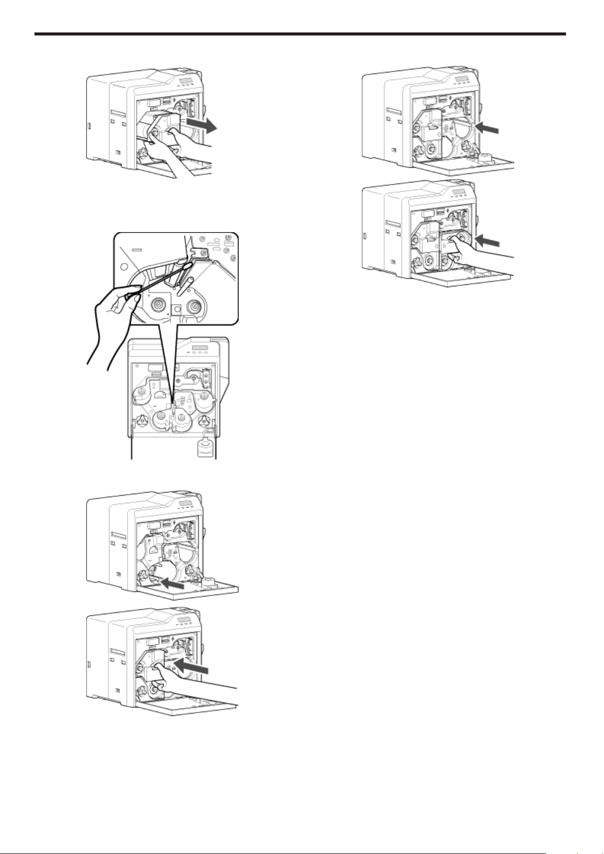
Maintenance
Press and hold down the cassette button, and remove the retransfer
3
film cassette (on the left)
.
Apply alcohol to a cotton swab (large), and use it to wipe the thermal
4
head
(Cotton swab and alcohol: sold separately)
v
Wipe the thermal head with care in the horizontal direction.
Insert the ink ribbon cassette along the guide rail until a “click”
6
sound is heard, followed by closing the printer door
.
.
.
Insert the retransfer film cassette along the guide rail until a “click”
5
sound is heard
.
.
42
Page 43

Servicing Based on Print Output
Colors Appear Faded or Dirt is Conspicuous
v
"Clean the cleaning roller." (A page 35)
v
"Clean the fan filter." (A page 36)
v
"Clean the card feed roller/heating roller." (A page 37)
v
"Clean the bobbin holders." (A page 40)
Card Jam
v
"Clean the cleaning roller." (A page 35)
v
"Clean the card load roller." (A page 36)
Error During Writing to or Reading of Magnetic Stripe Card
v
"Clean the magnetic head." (A page 39)
Lines Appear on Card after Printing
v
"Clean the thermal head." (A page 41)
Maintenance
43
Page 44

Troubleshooting
When an Error Message is Displayed
v
Check the error code and error code number displayed on the
operation panel.
.
List of Error Codes
v
Click on an error code below to jump to the page with the
corresponding error descriptions.
"44" (A page 45) "90" (A page 44) "91" (A page 44)
"92" (A page 44) "93" (A page 44) "94" (A page 44)
"95" (A page 44)
"A1" (A page 44) "A2" (A page 44) "A8" (A page 44)
"AB" (A page 45) "AC" (A page 45)
"B0" (A page 44) "B1" (A page 44) "B2" (A page 45)
"C1" (A page 45) "C2" (A page 45) "C3" (A page 45)
"D1" (A page 44) "D8" (A page 45)
"F0" (A page 45) "F1" (A page 45) "F2" (A page 45)
"F3" (A page 45) "F4" (A page 45) "F5" (A page 45)
"F6" (A page 45) "F8" (A page 45)
No Card
.
v
Cards have run out.
"Replenish the cards." (A page 31)
v
The card hopper is not installed.
Install the card hopper.
Memo:
v
The operation panel display appears blinking when the cards have
run out or when the card hopper is not installed.
Jam(Discharge) 94
.
v
Card jam near the card outlet.
"Remove the jammed card." (A page 51)
Jam(Retran.) 95
.
v
Card jam near the retransfer heating roller.
"Remove the jammed card." (A page 52)
Film Search A1
.
v
Retransfer film is broken.
"Repair the retransfer film." (A page 56)
MG Test Err A8
.
v
A writing error has occurred during magnetic encoder self-diagnosis.
Press KNB to reset the printer.
Ink Error B0
.
v
An incorrect ink ribbon is installed.
Install a correct ink ribbon.
Jam(Hopper) 90
.
v
Card jam near the card hopper and cleaning roller.
"Remove the jammed card." (A page 46)
Jam(TurnOver) 91
.
v
Card jam near the card turn over unit.
"Remove the jammed card." (A page 47)
Jam(MG) 92
.
v
Card jam in the magnetic encoder unit.
"Remove the jammed card." (A page 49)
Jam(Transfer) 93
.
v
Card jam in the card feed roller.
"Remove the jammed card." (A page 50)
Ink Search B1
.
v
Ink ribbon is broken.
"Repair the ink ribbon." (A page 54)
Door Open D1
.
v
The printer door is open.
Close the printer door, and press KNB to reset the printer.
v
Cleaning unit is not installed.
Install the cleaning unit, close the printer door, and press
KNB to reset the printer.
Memo:
v
The operation panel display appears blinking when the printer door
is open or when the cleaning unit is not installed.
Film Run Out A2
.
v
Retransfer film has run out.
"Replace with a new one." (A page 33)
44
Page 45

Troubleshooting
Ink Run Out B2
.
v
Ink ribbon has run out.
"Replace with a new one." (A page 32)
Hardware 44
.
v
A hardware failure has occurred on the printer.
Turn off and on the power again. If the same problem recurs, turn off
the power and consult our authorized dealers.
MG Mechanical AB
.
v
An error has occurred in the mechanical component of the magnetic
encoder.
Turn off and on the power again. If the same problem recurs, turn off
the power and consult our authorized dealers.
MG Hardware AC
TR Heater F1
.
v
The retransfer heating roller is faulty.
Turn off and on the power again. If the same problem recurs, turn off
the power and consult our authorized dealers.
TR Thermister F2
.
v
The retransfer heating roller thermistor is faulty.
Turn off and on the power again. If the same problem recurs, turn off
the power and consult our authorized dealers.
RR Overheat F3
.
v
The temperature of the bend remedy heating roller is too high.
Turn off and on the power again. If the same problem recurs, turn off
the power and consult our authorized dealers.
RR Heater F4
.
v
A hardware failure has occurred on the magnetic encoder.
Turn off and on the power again. If the same problem recurs, turn off
the power and consult our authorized dealers.
Cam Error C1
.
v
A heating roller operation error has occurred.
Turn off and on the power again. If the same problem recurs, turn off
the power and consult our authorized dealers.
HR Overheat C2
.
v
The temperature of the bend remedy heating roller or retransfer
heating roller is too high.
Turn off and on the power again. If the same problem recurs, turn off
the power and consult our authorized dealers.
Hardware D8
.
v
A hardware error has occurred during initialization.
Turn off and on the power again. If the same problem recurs, turn off
the power and consult our authorized dealers.
.
v
The bend remedy unit is faulty.
Turn off and on the power again. If the same problem recurs, turn off
the power and consult our authorized dealers.
RR Thermister F5
.
v
The bend remedy heating roller thermistor is faulty.
Turn off and on the power again. If the same problem recurs, turn off
the power and consult our authorized dealers.
Overcool F6
.
v
The operating ambient temperature of the printer is too low.
Check the temperature. If the same problem recurs within the range
of operating ambient temperature, turn off the power and consult our
authorized dealers.
Head Overheat F8
.
v
The temperature of the thermal head is too high.
Turn off and on the power again. If the same problem recurs, turn off
the power and consult our authorized dealers.
TR Overheat F0
.
v
The temperature of the retransfer heating roller is too high.
Turn off and on the power again. If the same problem recurs, turn off
the power and consult our authorized dealers.
Power Intrpt C3
.
v
An instantaneous interruption is detected.
Turn off and on the power again. If the same problem recurs, turn off
the power and consult our authorized dealers.
45
Page 46
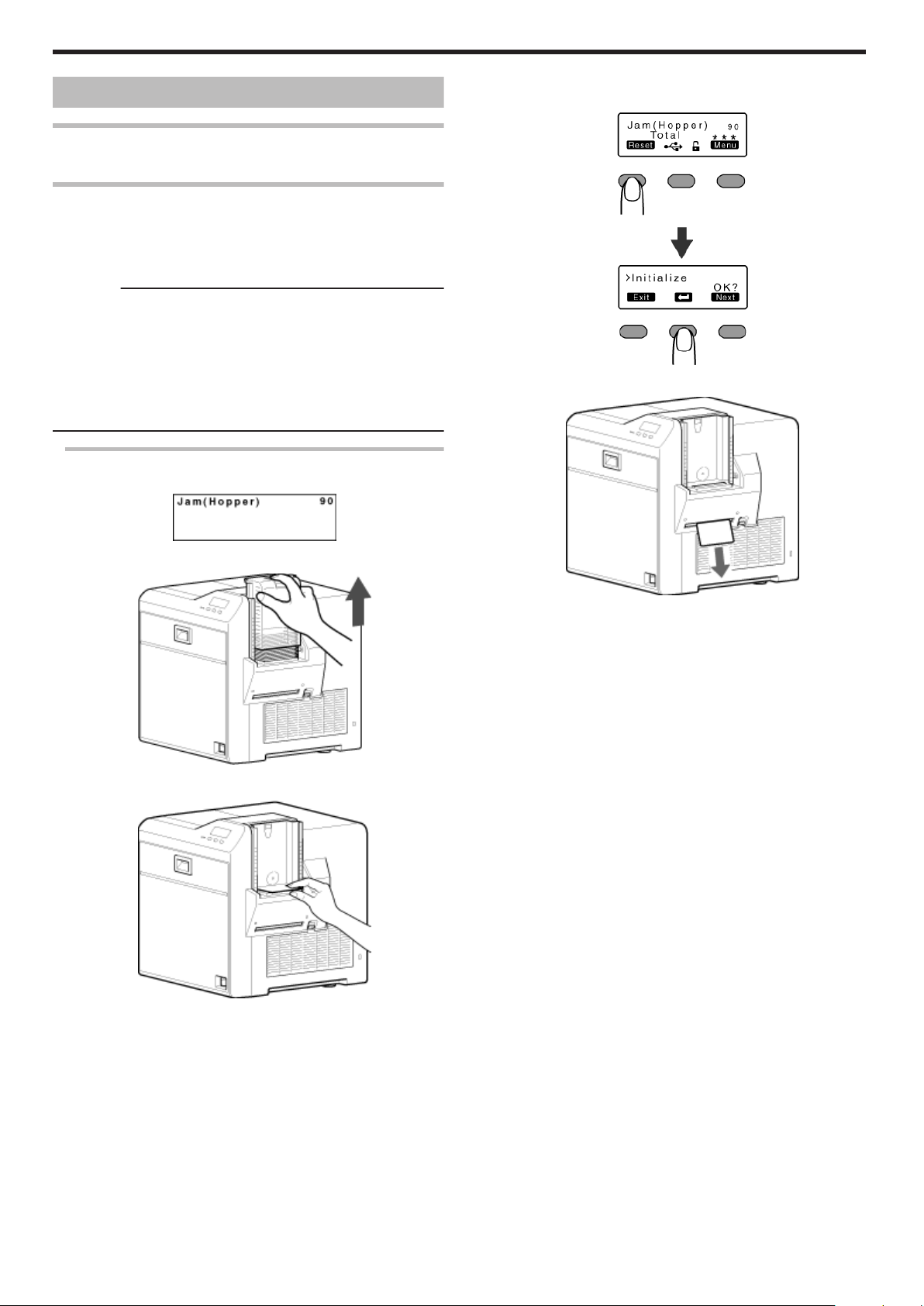
Troubleshooting
Cards
Cards have Run Out
v
"Replenish the cards." (A page 31)
Card Jam
v
Error codes are displayed on the operation panel according to the
location of the card jam.
v
Check the error code, and remove the card according to the
corresponding procedure.
Cautions:
v
If the card cannot be removed, do not try to do so forcibly. Consult
our authorized dealers or the servicing personnel.
v
If the security lock is on, deactivate it. After work is complete,
activate the security lock again.
v
Do not apply excessive force on the card hopper. Doing so may
damage it.
v
Do not touch the printing surface of the card. Touching it may cause
printing errors. Put on the supplied gloves when handling the cards.
Error Code Jam(Hopper) 90
v
Card jam near the card hopper and cleaning roller.
m
If the card cannot be removed by hand
A Press KNB to reset the printer
.
v
The card is discharged from the NG card outlet.
.
Detach the card hopper cover, and remove the unused cards
1
.
Remove the jammed card with a hand
2
"Go to step 3" (A page 46)
.
"If the card cannot be discharged" (A page 47)
"If the card cannot be removed by hand" (A page 46)
.
Return the unused cards to their original position
3
Install the card hopper cover
4
46
Page 47
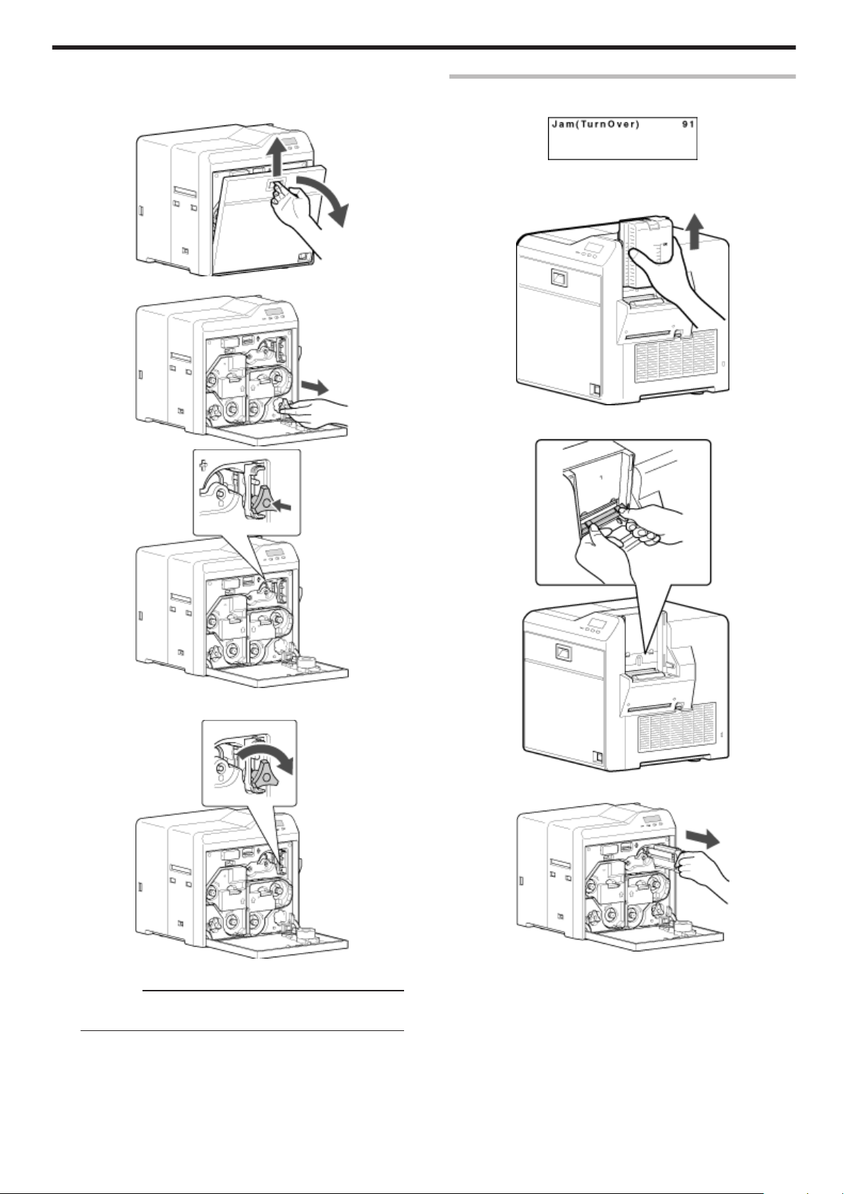
m
If the card cannot be discharged
A Turn off the power
B Open the printer door, and check the position of the jammed
card
.
C Attach the jog dial to the cleaning roller shaft
.
Error Code Jam(TurnOver) 91
v
Card jam near the card turn over unit.
.
Turn off the power
1
Remove the card hopper
2
.
Detach the card load slot cover
3
Troubleshooting
.
D Turn the cleaning roller shaft in the clockwise direction, while
checking the position of the card
.
E Remove the card after it is discharged from the card load slot
Cautions:
v
If the card cannot be removed, do not try to do so forcibly.
Consult our authorized dealers or the servicing personnel.
F Restore the jog dial to its original position, and close the
printer door
G Turn on the power
"Go to step 3" (A page 46)
.
Open the printer door, and remove the cleaning unit
4
.
47
Page 48

Troubleshooting
Remove the jammed card in the card turn over unit from the card
5
load slot
m
If the card cannot be removed
A Install the cleaning unit
B Attach the jog dial to the cleaning roller shaft and card turn
over unit shaft
"If the card cannot be removed" (A page 48)
.
Install the cleaning unit
6
Attach the jog dial to the card turn over unit shaft, and set the card
7
turn over unit to “Home Pos.”
v
“Home Pos.” is the position where the slit on the jog dial points to
the right and the card turn over unit is horizontal.
.
.
.
C Set the card turn over unit to “Home Pos.”
v
“Home Pos.” is the position where the slit on the jog dial
points to the right and the card turn over unit is horizontal.
.
Restore the jog dial to its original position
8
Install the card load slot cover and card hopper, and close the
9
printer door
Turn on the power
10
Cautions:
v
When a Jam(TurnOver) error occurs, the [Jam(TurnOver)]
message will not disappear after removing the jammed card until
the card turn over unit is set to “Home Pos.”.
v
If the printer door is opened when a Jam(TurnOver) error occurs, a
[Please Adjust Turn Unit Pos!] message will be displayed. Remove
the jammed card, and set the card turn over unit to “Home Pos.”.
48
.
v
If the card protrudes from the card turn over unit, turn the
cleaning roller shaft to move the card into the unit.
Page 49

v
Turning the card turn over unit moves the card inside the unit
outward. Turn the card turn over unit while turning the
cleaning roller shaft so that the card is retained inside the card
turn over unit, and set to “Home Pos.”.
.
Cautions:
v
Do not turn the card turn over unit forcibly if there is a card
inside the unit.
Doing so may jam the card and damage the printer.
D Turn the cleaning roller shaft in the clockwise direction
Error Code Jam(MG) 92
v
Card jam in the magnetic encoder unit.
.
1
Press KNB to reset the printer
.
v
The card is discharged from the NG card outlet.
Troubleshooting
.
E Remove the card after it is discharged from the card load slot
Cautions:
v
If the card cannot be removed, do not try to do so forcibly.
Consult our authorized dealers or the servicing personnel.
"Go to step 8" (A page 48)
.
49
Page 50

Troubleshooting
Error Code Jam(Transfer) 93
v
Card jam in the card feed roller.
.
1
Press KNB to reset the printer
.
v
The card is discharged from the NG card outlet.
m
If the card cannot be discharged
A Turn off the power, and detach the card hopper
.
B
Open the printer door, and check the position of the jammed
card
C
Attach the jog dial to the card feed roller shaft and cleaning roller shaft
.
.
.
D Turn the card feed roller shaft and cleaning roller shaft in the
clockwise direction, while checking the position of the card
.
v
Remove the card after it is discharged from the card load slot.
(For single-sided printers, the card is discharged from the NG
card outlet.)
Cautions:
v
If the card cannot be removed, do not try to do so forcibly.
Consult our authorized dealers or the servicing personnel.
E Restore the jog dial to its original position
F Install the card hopper, and close the printer door
G Turn on the power
50
Page 51
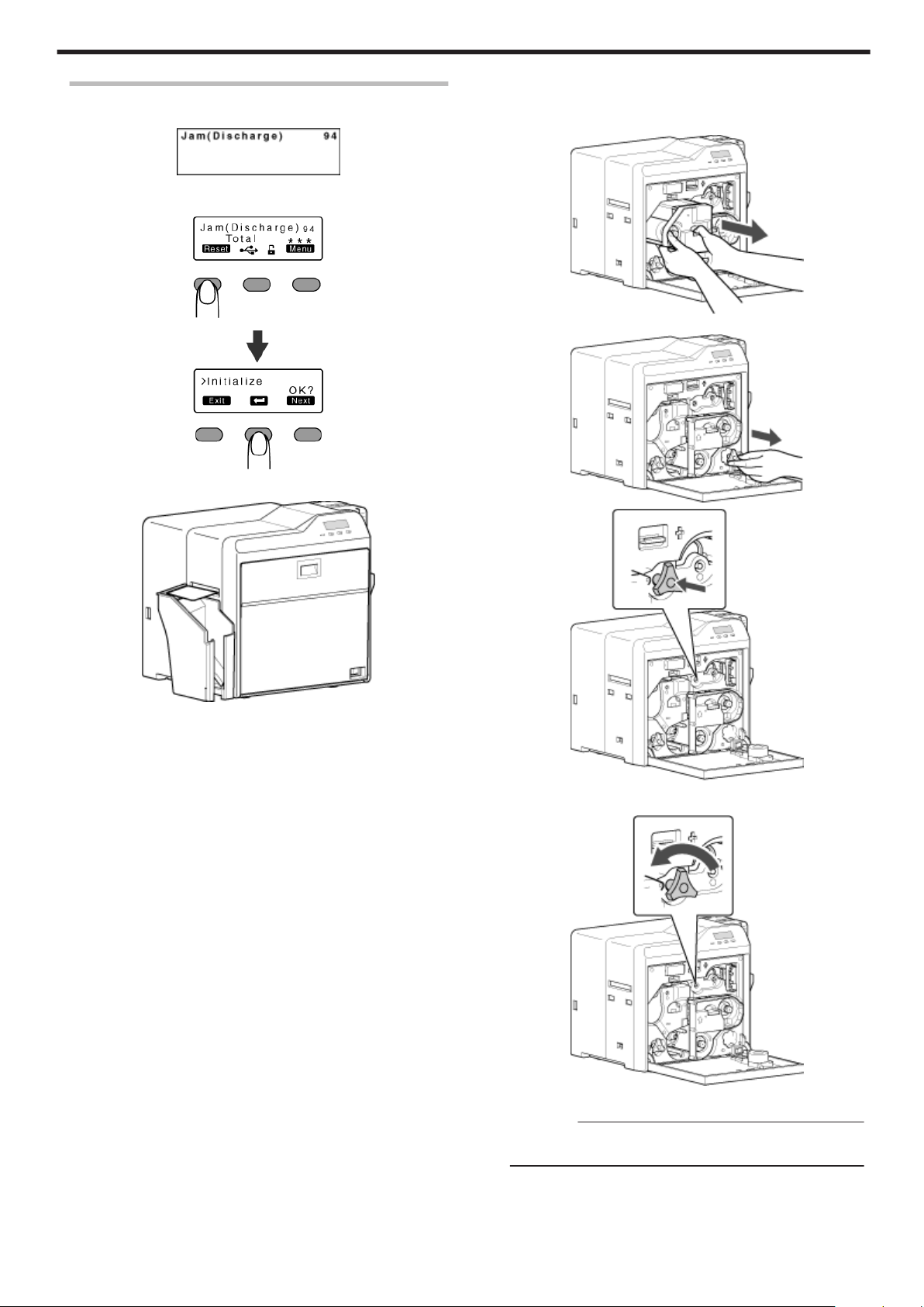
Error Code Jam(Discharge) 94
v
Card jam near the card outlet.
.
1
Press KNB to reset the printer
.
v
The card is discharged from the card outlet.
Troubleshooting
m
If the card cannot be discharged
A Turn off the power, and open the printer door
B Pull out the retransfer film cassette, and check the position of
the card
.
C Attach the jog dial to the card feed roller shaft
.
.
.
D Turn the card feed roller shaft in the anti-clockwise direction,
while checking the position of the card
.
v
The card is discharged from the card outlet.
Cautions:
v
If the card cannot be removed, do not try to do so forcibly.
Consult our authorized dealers or the servicing personnel.
E Restore the jog dial to its original position, and install the
retransfer film cassette
F Close the printer door, and turn on the power
51
Page 52

Troubleshooting
Error Code Jam(Retran.) 95
v
Card jam near the retransfer heating roller.
.
Open the printer door
1
v
A [Please Remove Jam Card!] or [Please Close Door] message
appears.
Pull out the retransfer film cassette
2
.
Cautions:
v
The card may be adhered to the retransfer film. Pull out the
retransfer film while taking care not to jam it.
v
If a [Please Close Door] message is displayed, the retransfer film
is stuck and the retransfer film cassette cannot be removed.
In this case, close the printer door before pulling out the retransfer
film cassette.
m
If the card is adhered to the retransfer film
v
Remove the jammed card with a hand.
.
Cautions:
v
The card may be very hot. Be careful not to burn your fingers
when removing the card.
"Go to step 4" (A page 52)
Remove the jammed card
3
"If the card is adhered to the retransfer film" (A page 52)
"If the card is inside the printer unit" (A page 53)
"If the card is caught in the card feed roller to the right of the
retransfer heating roller" (A page 53)
"If the card is caught in the card feed roller to the left of the retransfer
heating roller" (A page 54)
Install the retransfer film cassette, and close the printer door
4
5
Press K
v
A [Jam Card Removed?] message appears.
.
6
Press O
Cautions:
v
Initializing the printer without first removing the card will cause the
printer to malfunction. Be sure to remove the card then press O.
v
An [Initializing..] message appears, and initialization of the printer
starts.
52
.
Page 53

Troubleshooting
m
If the card is inside the printer unit
v
If the card is not drawn into the card feed roller and is left inside
the printer, use the tweezers (supplied) to remove the card.
A Turn off the power
B Check the position of the card that is left inside the printer
.
C Pick up the card using the tip of the tweezers (supplied)
v
Be careful not to drop the card inside the printer.
D Pull out the card slowly
m
If the card is caught in the card feed roller to the right of the
retransfer heating roller
A Turn off the power, and detach the card hopper
.
B Check the position of the card
C Attach the jog dial to the card feed roller shaft and cleaning
roller shaft
.
.
Cautions:
v
The card may be very hot. Be careful not to burn your fingers
when removing the card.
v
If the card cannot be removed, do not try to do so forcibly.
Consult our authorized dealers or the servicing personnel.
Memo:
Example of how to pick up the card
.
v
Pick up the card by following the diagram above.
E Install the retransfer film cassette, and close the printer door
.
F Turn on the power
"Go to step 5" (A page 52)
.
D Turn the card feed roller shaft and cleaning roller shaft in the
clockwise direction, while checking the position of the card
.
v
Remove the card after it is discharged from the card load slot.
(For single-sided printers, the card is discharged from the NG
card outlet.)
Cautions:
v
If the card cannot be removed, do not try to do so forcibly.
Consult our authorized dealers or the servicing personnel.
E
Restore the jog dial to its original position, and install the card hopper
F Install the retransfer film cassette, and close the printer door
G Turn on the power
"Go to step 5" (A page 52)
53
Page 54
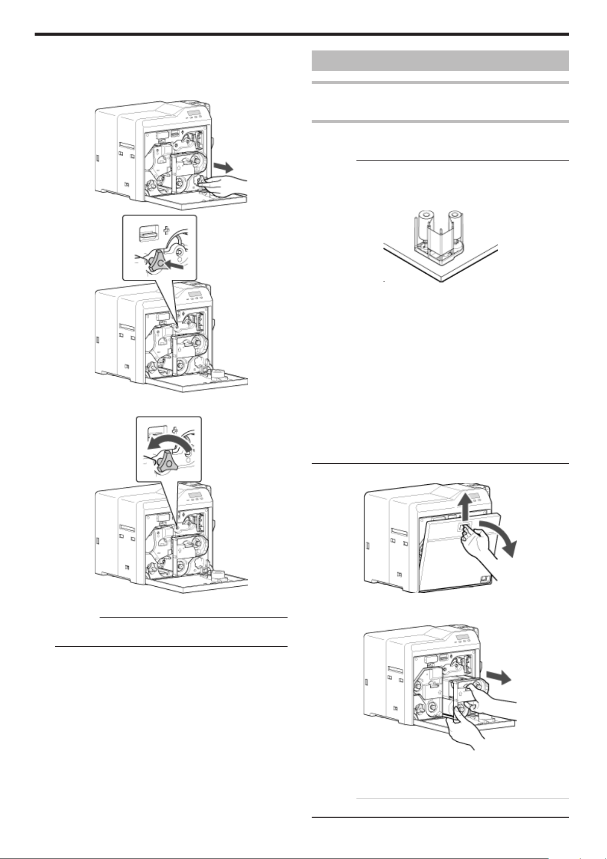
Troubleshooting
m
If the card is caught in the card feed roller to the left of the
retransfer heating roller
A Turn off the power
B Check the position of the card
C Attach the jog dial to the card feed roller shaft
.
.
D Turn the card feed roller shaft in the anti-clockwise direction,
while checking the position of the card
Ink Ribbon
Ink Ribbon has Run Out
v
"Replace with a new ink ribbon." (A page 32)
Ink Ribbon is Broken
v
Repair the ink ribbon.
Cautions:
v
If the security lock is on, deactivate it. After work is complete,
activate the security lock again.
v
Stand the cassette on a flat surface as illustrated in the diagram. Avoid
doing so on the floor as dust attached to it may cause printing errors.
.
v
Do not touch the inked surface (the side that faces outward when
installed) with your hand. Touching it may cause printing errors. Put
on the supplied gloves when handling the ink ribbon.
v
The cassette is heavy when the ink ribbon is loaded. To prevent the
cassette from dropping during handling, make sure to hold it with
both hands.
v
When installing a used ink ribbon, align the yellow side of the unused
ribbon with the arrow indicated on the label of the cassette. If the
position of the yellow side is not properly aligned, the print may turn
out light.
v
Do not perform any work on the printer door. Do not place heavy
objects or apply load on the printer. Doing so may damage it.
v
During replacement, clean the four bobbin holders on the printer. If
burrs produced by friction with the bobbins are attached to the
bobbin holders, they may fall onto the card, ink ribbon, or retransfer
film, causing printing errors.
"Cleaning the bobbin holders" (A page 40)
Open the printer door
1
.
v
The card is discharged from the card outlet.
Cautions:
v
If the card cannot be removed, do not try to do so forcibly.
Consult our authorized dealers or the servicing personnel.
E Restore the jog dial to its original position
F Install the retransfer film cassette, and close the printer door
G Turn on the power
"Go to step 5" (A page 52)
54
.
Press and hold down the cassette button, and remove the ink ribbon
2
cassette (on the right)
.
Cut away the broken portion, and attach the unused portion at the
3
supply side to the other end at the take-up side using an adhesive
tape, while making sure that the joint surface is even
Cautions:
v
Do not discard the used ribbon at the take-up side.
Page 55

Troubleshooting
Turn the take-up side using your hand until the broken portion can
4
no longer be seen
.
v
Align the yellow side of the unused portion with the arrow indicated
on the label of the cassette.
.
Remove any slack in the ink ribbon
5
.
Insert the cassette all the way in along the guide rail until a “click”
6
sound is heard, followed by closing the printer door
7
Press KNB to reset the printer
.
Memo:
v
To avoid printing errors, it is recommended that you forward by one
or two images after installing the ink ribbon cassette or retransfer film
cassette.
"Initializing printer when installing the cassette" (A page 22)
.
.
55
Page 56

Troubleshooting
Retransfer Film
Retransfer Film has Run Out
v
"Replace with a new retransfer film." (A page 33)
Retransfer Film is Broken
v
Repair the retransfer film.
Cautions:
v
If the security lock is on, deactivate it. After work is complete,
activate the security lock again.
v
Stand the cassette on a flat surface as illustrated in the diagram.
Avoid doing so on the floor as dust attached to it may cause printing
errors.
.
v
Do not touch the retransfer face (the side that faces outward when
installed) with your hand. Touching it may cause printing errors. Put
on the supplied gloves when handling the retransfer film.
v
The cassette is heavy when the retransfer film is loaded. To prevent
the cassette from dropping during handling, make sure to hold it with
both hands.
v
When installing a used retransfer film, align the unused side of the
film with the arrow indicated on the label of the cassette. Improper
alignment may result in errors, or the print may turn out light.
v
Do not perform any work on the printer door. Do not place heavy
objects or apply load on the printer. Doing so may damage it.
v
During replacement, clean the four bobbin holders on the printer. If
burrs produced by friction with the bobbins are attached to the
bobbin holders, they may fall onto the card, ink ribbon, or retransfer
film, causing printing errors.
"Cleaning the bobbin holders" (A page 40)
Open the printer door
1
Turn the take-up side using your hand until the broken portion can
4
no longer be seen
.
v
Align the film side of the unused portion with the arrow indicated on
the label of the cassette.
Remove any slack in the film
5
.
Insert the cassette all the way in along the guide rail until a “click”
6
sound is heard, followed by closing the printer door
.
.
Press and hold down the cassette button, and remove the retransfer
2
film cassette (on the left)
.
Cut away the broken portion, and attach the unused portion at the
3
supply side to the other end at the take-up side using an adhesive
tape, while making sure that the joint surface is even
Cautions:
v
Do not discard the used retransfer film at the take-up side.
.
7
Press KNB to reset the printer
.
Memo:
v
To avoid printing errors, it is recommended that you forward by one or two
images after installing the ink ribbon cassette or retransfer film cassette.
"Initializing printer when installing the cassette" (A page 22)
56
Page 57

Troubleshooting
Unable to Fit Retransfer Film Cassette into Printer
v
With the printer door closed, turn on the power to cancel the
transport mode.
v
While in the transport mode, the retransfer film cassette cannot be
installed to the printer with the retransfer film loaded.
"Transport Mode Setting" (A page 29)
Unable to Produce Desired Printing Results
Lines Appear on Card after Printing
v
"Clean the thermal head." (A page 41)
Colors on Card Appear Faded after Printing
v
"Clean the cleaning roller." (A page 35)
v
"Clean the fan filter." (A page 36)
v
"Clean the card feed roller/heating roller." (A page 37)
v
"Clean the bobbin holders." (A page 40)
Peeling Occurs on Card after Printing
v
"Check the retransfer mode settings." (A page 111)
Overall Printing Quality is Poor
v
"Clean the cleaning roller." (A page 35)
v
"Clean the fan filter." (A page 36)
v
"Clean the card feed roller/heating roller." (A page 37)
v
"Clean the bobbin holders." (A page 40)
v
Is the printing face of the card dirty?
Use a clean card.
Card is Printed in a Single Color
v
Is the print setting set to single-color printing?
v
Is the software application setting set to single-color printing?
Check the print settings.
Strange Characters or Images are Printed
v
Is the driver for this printer selected on the computer?
Select the driver for this printer.
v
Is the USB cable connection loose?
Plug in the USB cable properly.
Retransfer cannot be Performed Successfully
v
Is the printing face of the card dirty?
Use a clean card.
v
Is the surrounding temperature or card surface temperature too
low?
Use the printer when the surrounding temperature is sufficiently high.
v
Is the retransfer speed setting value too high?
Set to a value that is smaller than the standard value, +2 (i.e.,
between +1 and -3).
v
Is the temperature of the retransfer heating roller too low?
Set to a value that is larger than the standard value, +1 (i.e., +2).
57
Page 58

Troubleshooting
Printer not Operating as Desired
Card is not Fed into the Printer
v
Is the card load roller dirty?
"Clean the card load roller." (A page 36)
v
Is the cleaning roller dirty?
"Clean the cleaning roller." (A page 35)
v
Is the card thickness correctly adjusted?
"Check the adjusted card thickness." (A page 63)
v
Are the cards adhered to one another?
When using new cards, set them after making sure that they are not
adhered to each other due to static.
Power does not Turn On
v
Is the power switch turned off? (¡ position)
Turn on the power. (I position)
v
Is the power cord disconnected?
Plug in the power cord properly.
v
Is there electricity supply from the outlet?
Try connecting another electrical device to the outlet. If the device
works normally, then it could be due to malfunctioning of the printer.
Please consult our authorized dealers.
Printing does not Start or Stops Halfway
v
Is the printer door open?
"Close the printer door properly, and reset the printer." (A page 22)
v
Is the printer connected to a computer?
Connect the printer to a computer correctly using a USB/LAN cable.
v
Is the length of the USB cable too long?
A USB cable with a length of not more than 2 m is recommended.
v
Are cards set into the printer?
"Set the cards correctly." (A page 31)
v
Is the ink ribbon installed?
"Install the ink ribbon correctly." (A page 32)
v
Is the retransfer film installed?
"Install the retransfer film correctly." (A page 33)
v
Is the driver for this printer selected?
Select the driver for this printer.
Before Sending Printer for Repair
Enter the symptoms into the troubleshooting sheet.
v
Clicking the Print icon displays a PDF file.
v
Print out the PDF file and enter accordingly.
58
Page 59

Setup
Installation and Connection
Printer Installation
Cautions:
v
Using the printer in an environment beyond the operating ambient
temperature range may result in retransfer or printing errors. Check
the “Precautions on installation location” and “Operating environment
conditions” specifications.
"Precautions on installation location" (A page 6)
"Operating environment conditions" (A page 10)
Ventilation holes for the cooling fan are located at the rear and side of
the printer.
v
Install the printer by allowing a clearance of at least 20 cm between
its sides and surrounding walls.
.
v
Allow a clearance of at least 10 cm between the rear of the printer
and the wall.
Power Cord Connection
Insert the power cord (supplied) to the AC inlet at the rear of the
1
printer
.
Plug the power cord (supplied) into an outlet
2
Memo:
v
Make use of an AVR (automatic voltage regulator) to prevent any
fluctuation in voltage. Alternatively, an uninterruptible power supply
is recommended in case momentary power failure occurs.
Cautions:
v
Make sure that the power outlet is grounded and used as a
dedicated power source for the printer.
v
Plug the power cord of the printer directly to the outlet. Do not share
the same outlet with other devices.
.
v
Do not place any object on the printer.
Card Stacker (Supplied)
Hook the tab on the card stacker to the card stacker attachment slot
1
.
A Card outlet
B Card stacker attachment slot
C Tab
D Card stacker
Memo:
v
The card stacker is able to store up to about 100 cards with a
thickness of 0.76 mm.
.
59
Page 60
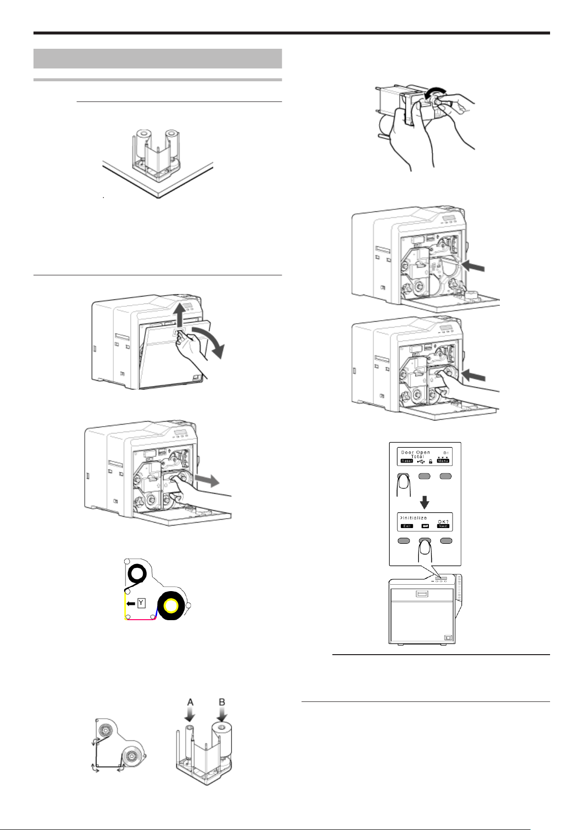
Setup
Printing Media
Installing the Ink Ribbon
Cautions:
v
Stand the cassette on a flat surface as illustrated in the diagram. Avoid
doing so on the floor as dust attached to it may cause printing errors.
.
v
Do not touch the inked surface (the side that faces outward when
installed) with your hand. Touching it may cause printing errors. Put
on the supplied gloves when handling the ink ribbon.
v
The cassette is heavy when the ink ribbon is loaded. To prevent the cassette
from dropping during handling, make sure to hold it with both hands.
v
Do not perform any work on the printer door. Do not place heavy
objects or apply load on the printer. Doing so may damage it.
Open the printer door
1
Remove any slack in the ink ribbon
4
A Hold the cassette.
B Turn the knob in the direction indicated by the arrow.
.
Insert the cassette all the way in along the guide rail until a “click”
5
sound is heard, followed by closing the printer door
.
.
Press and hold down the cassette button, and remove the ink ribbon
2
cassette (on the right)
.
Install a new ink ribbon
3
v
Install while referring to the indication on the label of the cassette.
.
A With the inked surface facing outward, align the yellow side of the
unused ribbon with the arrow on the cassette, and unwind it
along the three shafts.
B Insert the ink ribbon firmly into the bobbin holders with the ribbon
set to the far end of the guides.
v
A: take-up side (black)
v
B: unused side (yellow)
.
6
Press KNB to reset the printer
.
Memo:
v
To avoid printing errors, it is recommended that you forward by one
or two images after installing the ink ribbon cassette or retransfer film
cassette.
"Initializing printer when installing the cassette" (A page 22)
60
.
Page 61
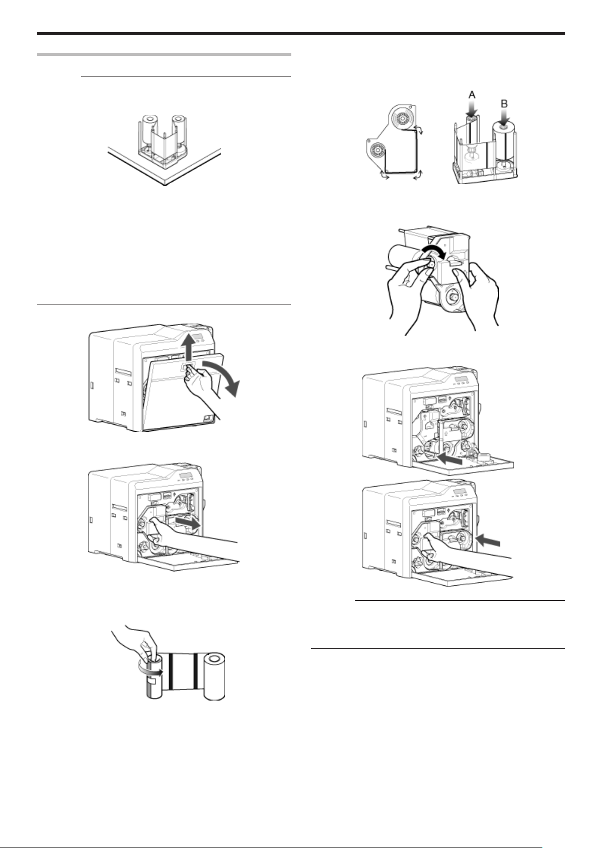
Installing the Retransfer Film
Cautions:
v
Stand the cassette on a flat surface as illustrated in the diagram.
Avoid doing so on the floor as dust attached to it may cause printing
errors.
Setup
Insert the retransfer film firmly into the bobbin holders with the film
C
set to the far end of the guides.
v
A: take-up side (black)
v
B: unused side (green)
.
v
Do not touch the retransfer face (the side that faces outward when
installed) with your hand. Touching it may cause printing errors. Put
on the supplied gloves when handling the retransfer film.
v
The cassette is heavy when the retransfer film is loaded. To prevent
the cassette from dropping during handling, make sure to hold it with
both hands.
v
When installing a new film, make sure that at least three black lines
are wound onto the take-up side. Insufficient winding may cause the
printer to malfunction.
v
Do not perform any work on the printer door. Do not place heavy
objects or apply load on the printer. Doing so may damage it.
Open the printer door
1
.
Press and hold down the cassette button, and remove the retransfer
2
film cassette (on the left)
.
Remove any slack in the film
4
A Hold the retransfer film cassette.
B Turn the knob in the direction indicated by the arrow.
.
Insert the cassette all the way in along the guide rail until a “click”
5
sound is heard, followed by closing the printer door
.
Install a new retransfer film
3
v
Install while referring to the indication on the label of the cassette.
A When installing the retransfer film, make sure that at least three
black lines are wound onto the take-up side.
.
B With the retransfer face facing outward, align the unused side of
the film with the arrow on the cassette, and unwind it along the
three shafts.
.
.
Cautions:
v
While in the transport mode, the retransfer film cassette cannot be
installed to the printer with the retransfer film loaded. With the printer
door closed, turn on the power to cancel the transport mode.
"Transport Mode Setting" (A page 29)
61
Page 62

Setup
6
Press KNB to reset the printer
.
Memo:
v
To avoid printing errors, it is recommended that you forward by one
or two images after installing the ink ribbon cassette or retransfer film
cassette.
"Initializing printer when installing the cassette" (A page 22)
Setting Cards
v
The card hopper is able to store up to about 100 cards with a
thickness of 0.76 mm.
Cautions:
v
Get ready cards that are designated by the authorized dealer.
v
If the security lock is on, deactivate it. After work is complete,
activate the security lock again.
v
Do not touch the printing surface of the card. Touching it may cause
printing errors. Put on the supplied gloves when handling the cards.
v
To prevent card jams from occurring, limit the number of cards
stored in the card hopper at any time to about 100 pieces regardless
of the card thickness.
v
When using new cards, set them after making sure that they are not
adhered to each other due to static.
v
Align the cards before setting them in the printer. Otherwise, the card
hopper cover may not close properly, and this may damage the
printer.
v
Printing the card on the side with the magnetic stripe may cause
printing errors or damage to the card’s functions. If you want to do
so, please consult our authorized dealers in advance.
v
To set cards with both functions (magnetic stripe and contact IC),
follow the procedure for setting the contact IC card.
Set the card hopper knob to [OPEN]
1
.
Lift to remove the card hopper cover
2
.
62
Page 63

Align the orientation of the cards, and set them in the printer
3
m
Magnetic stripe cards
v
Set the card with the magnetic stripe facing upward and toward
the printer, or facing downward and toward you.
.
m
ISO contact IC cards
v
Set the card with the Contact IC terminal facing upward and
toward the rear of the printer, or downward and toward the rear of
the printer.
v
For single-sided printers, set the cards with the IC terminal facing
down and toward the rear of the printer.
.
Install the card hopper cover, and set the card hopper knob to
4
[LOCK]
m
Adjusting card thickness
v
The thickness of a card that is adjustable is between 0.25 mm and
1.00 mm.
This is adjusted to a thickness of 0.76 mm by default.
A Set the card hopper knob to [LOCK]
.
B Remove the card hopper
Setup
.
C Insert a ballpoint pen into the card separator hole, and turn
slowly
v
Adjust according to the range of the card thickness used.
.
.
Memo:
v
If the card cannot be discharged during printing, adjust the card
thickness by turning the card separator in the clockwise
direction by one scale at a time.
v
If two cards are discharged at a time during printing, adjust the
card thickness by turning the card separator in the anticlockwise direction by one scale at a time.
D Install the card hopper
.
63
Page 64

Setup
Printer and Computer Connection
Connecting with a USB Cable
Cautions:
v
While printing is in progress, do not turn off the power of the
computer, or switch it to the sleep or standby mode. Doing so may
stop the movement of the cards inside the printer.
v
Plug the USB cable in correctly and firmly.
v
Do not connect the cable to the USB connectors on the monitor or
keyboard of the computer. The printer may not be correctly
recognized.
v
When using a USB hub, make use of one that is directly connected
to the computer.
Turn off the power of the printer and computer
1
Plug the USB cable into the USB cable connection terminal at the
2
rear of the printer, and "Cable clamp" (A page 8) pass the USB
cable through the cable clamp
Connecting with a LAN Cable
Cautions:
v
Plug the LAN cable in correctly and firmly.
v
Make use of a shielded LAN cable to avoid any malfunction.
v
If a USB cable is also connected at the same time when the power is
turned on, priority will be given to USB.
Turn off the power of the printer and computer
1
Plug the LAN cable into the LAN cable connection terminal at the
2
rear of the printer
.
Plug the LAN cable into the connection terminal of the hub that is
3
installed on the network that the computer is connected to
.
Cautions:
v
As illustrated in the diagram, do not pull the USB cable excessively
toward the cable clamp. Doing so may subject the USB connector of
the printer to stress, thus resulting in connection problems.
.
Plug the other end of the USB cable into the USB cable connection
3
terminal of the computer
Connecting Multiple Printers
v
To connect multiple printer units to one computer via USB, assign a
different unit number from 1 to 10 to each of the printers.
"Unit Number Setting" (A page 28)
v
To connect multiple printers to the same network, set a different IP
address for each printer.
64
Page 65

Setup
Computer Settings
m
System Requirements
v
The printer software runs under the following environments.
v
Microsoft Windows Vista 32 bit (Service Pack 1)
v
Microsoft Windows XP 32 bit (Service Pack 2/3)
v
Microsoft Windows 2000 Professional 32bit (Service Pack 4)
v
"Software" (A page 65)
v
"Install" (A page 65)
v
"Uninstall" (A page 80)
v
"IPSec" (A page 84)
v
"Printer Driver Settings" (A page 87)
v
"Port Monitor Settings" (A page 106)
v
"Status Monitor Settings" (A page 107)
v
"Inline Encoding" (A page 118)
v
"List of Error Codes" (A page 120)
v
"Frequently Asked Questions" (A page 123)
Software
v
Using the installer (automatic execution program) enables easy
installation of the printer software, as well as opening of the
Electronic Manual.
v
The installer application installs programs based on the Windows
language settings. To change the language setting of a program,
use the language selection pull-down menu.
Software License Agreement
v
Users need to agree to the terms and conditions in the “Software
License Agreement” before using the software. Please read through
the License Agreement.
Install
Cautions:
v
To install the software, log into the system as an administrative user
(Administrators group).
v
A part of the illustrations in this Electronic Manual may not be
displayed depending on the computer’s environment. Skip the
procedures in this case.
v
"Printer Driver" (A page 65)
v
"Network Sharing of Printer" (A page 73)
v
"Status Monitor" (A page 75)
v
"USB Driver" (A page 76)
v
"Electronic Manual" (A page 79)
Printer Driver
Installing the Printer Driver
USB Connection
Cautions:
v
Do not turn on the power of the printer until instruction asking you to
do so appears on the installer.
v
Do not connect the printer to the USB until instruction asking you to
do so appears on the installer.
v
You need to enable the USB hub before connecting the printer via
this hub. Do not connect the printer to the USB hub until instruction
asking you to do so appears.
v
Exit all applications that are currently running.
v
If document printing is currently in progress, wait for all the jobs to
complete.
Start up Windows, and set the supplied CD-ROM into the computer
1
v
A card printer setup screen appears.
.
Memo:
v
If the CD-ROM drive of the computer is set to run automatically, the
installer will be executed automatically.
If the installer is not automatically initiated, double-click “SETUP.exe”
in the CD-ROM.
v
If you are not using the “SETUP.exe” automatic execution program
in the CD-ROM, start the installer for the printer driver by doubleclicking the following file in the CD-ROM: “English\USB_Soft
\install.exe”.
65
Page 66

Setup
m
Windows Vista
v
A [AutoPlay] screen appears.
Click [Next]
5
v
A start installation screen appears.
.
v
Clicking [Run SETUP.exe] displays the [User Account Control]
screen.
v
Clicking [Allow] displays the card printer setup screen.
Select the [Printer Driver] checkbox on the card printer setup screen
2
A Select the language to use from the [Language] pull-down menu
v
Selecting [Japanese] switches the program to the Japanese
version.
v
Selecting [English] switches the program to the English version.
B Select [USB connection] from [Interface]
C Select [Install] under [Action], and select the [Printer Driver]
checkbox
Memo:
v
You can select the [Status Monitor] and [Electronic Manual]
checkboxes to install them simultaneously. Selecting all checkboxes
starts installation in the order of the Electronic Manual, printer driver,
and status monitor.
v
The same status monitor can be used for printers connected via
USB and Ethernet.
v
Clicking [Open the Electronic Manual] opens the Electronic
Manual.
v
Clicking [Exit] ends the installation.
Click [Next]
3
v
A [Installation of CX-7000 USB printer] screen appears.
.
Read through the “Software License Agreement”
4
v
If you accept the terms and conditions, select [I agree] to start
installation.
v
If you do not agree, click [Cancel] to stop the installation.
.
Check the details, followed by clicking [Next]
6
v
A screen for setting [Printer model] and [Printer name] appears.
.
A Select a [Printer model] according to the unit number of the printer
"Unit Number Setting" (A page 28)
v
Select a [Printer model] according to the unit number of the
printer. Installation may fail if the combination is incorrect.
Printer Unit
Number
1 (Factory
Printer Model
USB Device Name
Options
CX-7000 U1 CX-7000 U1
Setting)
2 CX-7000 U2 CX-7000 U2
3 CX-7000 U3 CX-7000 U3
4 CX-7000 U4 CX-7000 U4
5 CX-7000 U5 CX-7000 U5
6 CX-7000 U6 CX-7000 U6
7 CX-7000 U7 CX-7000 U7
8 CX-7000 U8 CX-7000 U8
9 CX-7000 U9 CX-7000 U9
10 CX-7000 U10 CX-7000 U10
B Enter the [Printer name]
C Select the [Make this the default printer.] checkbox if necessary
Memo:
v
Doing so enables you to set it as a default printer after installation
is complete.
66
Click [Next]
7
v
A screen for entering the shared name appears.
Page 67

v
Enter the shared name when you are sharing a printer.
.
Memo:
v
You can also set the shared name after installation is complete.
Click [Next]
8
v
A port selection screen appears.
v
Select [CX-7000U Port] under [Create a new port].
m
Windows Vista
v
A [Windows Security] screen appears.
.
A Click [Install] part
v
A USB cable connection instruction screen appears.
Setup
.
Click [Next]
9
v
An install information confirmation screen appears.
.
Check the installation information, followed by clicking [Finish]
10
v
To change the settings, click [Back].
.
Connect the printer and computer using the USB cable
11
Turn on the power of the printer
12
v
Installation starts automatically after the printer is detected.
v
Installation does not start if connection is improper. When this
occurs, check the connection.
m
Windows XP
A [Found New Hardware Wizard] screen appears.
.
A Select [No, not this time], and click [Next]
v
An installation method selection screen appears.
m
Windows XP
v
A [Software Installation] screen appears.
.
A Click [Continue Anyway]
.
67
Page 68

Setup
B Select [Install the software automatically (Recommended)], and
click [Next]
v
A [Hardware Installation] screen appears.
v
A [CX-7000U Port] screen appears.
.
C Click [Continue Anyway]
v
A “Completing the Found New Hardware Wizard” screen
appears.
.
D Click [Finish]
v
A [Software Installation] screen appears.
.
Select the [Property] tab
13
A Select this printer from [Printer List]
Memo:
v
USB connection is improper if “No Device” appears in the [Printer
List]. When this occurs, end the installation process and reinstall
the program.
v
If “No Selection” appears in the [Printer List], select a USB device
name that coincides with the printer unit number that is currently
being installed from the pull-down list.
B Enter the port name
Click [OK]
14
m
Windows XP
v
A [Software Installation] screen appears.
.
A Click [Continue Anyway]
.
E Click [Continue Anyway]
m
Windows 2000
v
A [Digital Signature Not Found] screen appears.
.
A Click [Yes]
m
Windows Vista
v
A [Windows Security] screen appears.
.
A Click [Install] part
68
Page 69

Setup
m
Windows 2000
v
A [Digital Signature Not Found] screen appears.
.
A Click [Yes]
v
A printer installation complete screen appears.
m
Windows 2000 (Example)
.
Cautions:
v
To delete a printer, execute “Uninstall printer driver” after restarting
Windows.
Ethernet (LAN) Connection
Cautions:
v
Configure the IP address and other necessary settings for the printer
in advance.
v
Do not connect the printer to the USB port.
v
Do not connect the printer to the Ethernet (LAN) until instruction
asking you to do so appears on the installer.
v
Do not turn on the power of the printer until instruction asking you to
do so appears on the installer.
v
You need to enable the LAN hub before connecting the printer via
this hub.
v
Exit all applications that are currently running.
v
If document printing is currently in progress, wait for all the jobs to
complete.
.
Click [Finish]
15
v
Exits the installation program.
Open “Printers” in [Control Panel]
16
v
Check to ensure that the printer is added.
m
Windows XP (Example)
.
m
Windows Vista (Example)
Start up Windows, and set the supplied CD-ROM into the computer
1
v
A card printer setup screen appears.
.
Memo:
v
If the CD-ROM drive of the computer is set to run automatically, the
installer will be executed automatically.
If the installer is not automatically initiated, double-click “SETUP.exe”
in the CD-ROM.
v
If you are not using the “SETUP.exe” automatic execution program
in the CD-ROM, start the installer for the printer driver by doubleclicking the following file in the CD-ROM: “English\LAN_Soft
\install.exe”.
.
69
Page 70

Setup
m
Windows Vista
v
A [AutoPlay] screen appears.
Click [Next]
5
v
A start installation screen appears.
.
v
Clicking [Run SETUP.exe] displays the [User Account Control]
screen.
v
Clicking [Allow] displays the card printer setup screen.
Select the [Printer Driver] checkbox on the card printer setup screen
2
A Select the language to use from the [Language] pull-down menu
v
Selecting [Japanese] switches the program to the Japanese
version.
v
Selecting [English] switches the program to the English version.
B Select [Ethernet connection] from [Interface].
C Select [Install] under [Action], and select the [Printer Driver]
checkbox
Memo:
v
You can select the [Status Monitor] and [Electronic Manual]
checkboxes to install them simultaneously. Selecting all checkboxes
starts installation in the order of the Electronic Manual, status
monitor, and printer driver.
v
The same status monitor can be used for printers connected via
USB and Ethernet.
v
Clicking [Open the Electronic Manual] opens the Electronic
Manual.
v
Clicking [Exit] ends the installation.
Click [Next]
3
v
A [Installation of CX-7000 Ethernet printer] screen appears.
.
Connect the printer and computer using a LAN cable
6
Turn on the power of the printer
7
Check the details, followed by clicking [Next]
8
v
A screen for setting [Printer model] and [Printer name] appears.
.
A Select a [Printer model]
B Enter the [Printer name]
C Select the [Make this the default printer.] checkbox if necessary
Memo:
v
Doing so enables you to set it as a default printer after installation
is complete.
.
Read through the “Software License Agreement”
4
v
If you accept the terms and conditions, select [I agree] to start
installation.
v
If you do not agree, click [Cancel] to stop the installation.
Click [Next]
9
v
A screen for entering the shared name appears.
v
Enter the shared name when you are sharing a printer.
.
Memo:
v
You can also set the shared name after installation is complete.
70
Page 71

Click [Next]
10
v
A port selection screen appears.
v
Select [CX-7000N Port] under [Create a new port].
.
Click [Next]
11
v
An install information confirmation screen appears.
m
Windows Vista
v
A [Windows Security Alert] screen appears.
.
A Click [Unblock]
v
The program will fail to function properly if you click on [Keep
blocking].
v
A [CX-7000N Port] screen appears.
Setup
.
Check the installation information, followed by clicking [Finish]
12
v
To change the settings, click [Back].
m
Windows XP
v
A [Software Installation] screen appears.
.
A Click [Continue Anyway]
v
A [Windows Security Alert] screen appears.
.
Select the [Property] tab
13
A Select this printer from [Printer List]
v
When connecting using the IPv4 address, select [IPv4], followed
by clicking [Find...] to search for the printer. After clicking [IPv4],
you can search for the printer by directly entering the IPv4 address
in the [Printer List].
v
When connecting using the IPv6 address, select [IPv6], followed
by clicking [Find...] to search for the printer. After clicking [IPv6],
you can search for the printer by directly entering the IPv6 address
in the [Printer List].
Memo:
v
Ethernet (LAN) connection is improper if “Not Connected” appears
in the [Printer List]. If the printer that is currently being installed
cannot be found by clicking [Find...], end the installation process
and reinstall the program.
v
If “Not Selected” appears in the [Printer List], select an item that
coincides with the IP address of the printer that is currently being
installed from the pull-down list.
B Enter the [Port Name]
Click [OK]
14
m
Windows XP
v
A [Software Installation] screen appears.
.
B Click [Unblock]
v
The program will fail to function properly if you click on buttons
other than [Unblock].
.
A Click [Continue Anyway]
71
Page 72

Setup
m
Windows Vista
v
A [Windows Security] screen appears.
.
A Click [Install] part
m
Windows 2000
v
A [Digital Signature Not Found] screen appears.
m
Windows Vista (Example)
.
m
Windows 2000 (Example)
.
Cautions:
v
To delete a printer, execute “Uninstall printer driver” after restarting
Windows.
.
A Click [Yes]
v
A printer installation complete screen appears.
.
Click [Finish]
15
v
Exits the installation program.
Open “Printers” in [Control Panel]
16
v
Check to ensure that the printer is added.
m
Windows XP (Example)
Update of Printer Driver
To update
Delete the existing printer driver
1
"Uninstalling the Printer Driver" (A page 80)
Re-install the printer driver
2
"Installing the Printer Driver" (A page 65)
72
.
Page 73
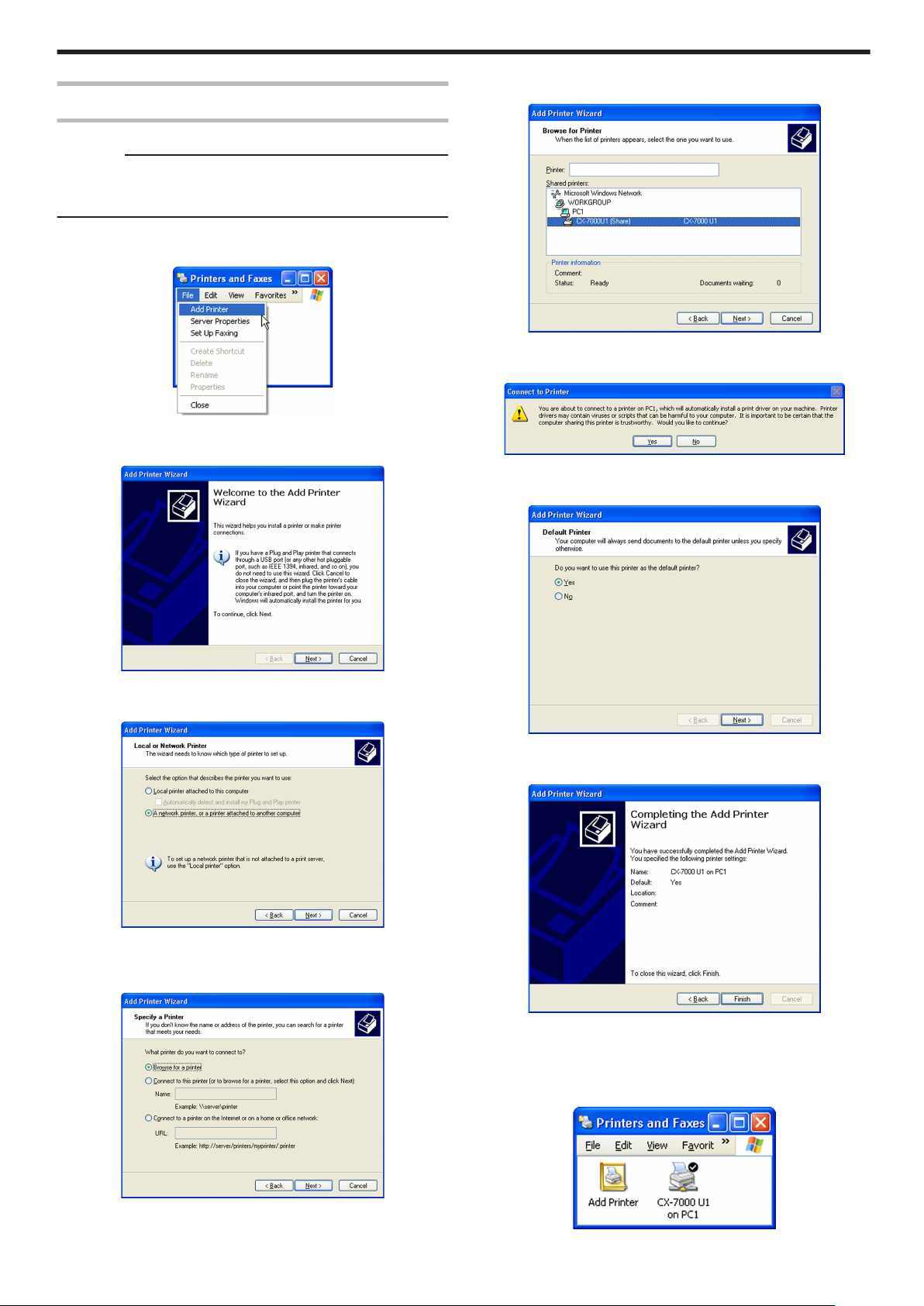
Network Sharing of Printer
Windows XP/ Windows 2000
Cautions:
v
Check to ensure that you can access the computer to which the
printer is connected.
v
Check also to ensure that the printer can be shared.
Open “Printers” in [Control Panel]
1
v
A [Printers and Faxes] screen appears.
.
Click [Add Printer] under the [File] menu
2
v
A “Welcome to the Add Printer Wizard” screen appears.
Select [Browse for a printer], and click [Next]
5
v
A “Browse for Printer” screen appears.
.
Select a printer from [Shared printers], and click [Next]
6
v
A [Connect to Printer] screen appears.
.
Click [Yes]
7
v
A “Default Printer” screen appears.
Setup
.
Click [Next]
3
v
A printer type selection screen appears.
.
Select [A network printer, or a printer attached to another computer],
4
and click [Next]
v
A “Specify a Printer” screen appears.
.
Select [Yes] if necessary, and click [Next]
8
v
A “Completing the Add Printer Wizard” screen appears.
.
Check the details, followed by clicking [Finish]
9
v
Network sharing of the printer is complete.
Open “Printers” in [Control Panel]
10
v
Check to ensure that the printer is added.
.
.
73
Page 74

Setup
Cautions:
v
When the access authority of the computer is not proper, the printer
may not be able to perform printing even if installation of the printer
driver is completed.
Ensure that the access authority is proper according to the
instructions of the network administrator.
Select a printer, and click [Next]
4
v
A driver installation confirmation screen appears.
Windows Vista
Cautions:
v
Check to ensure that you can access the computer to which the
printer is connected.
v
Check also to ensure that the printer can be shared.
Open “Printers” in [Control Panel]
1
v
A [Printer] screen appears.
.
Click [Add a printer] in the toolbar
2
v
A printer selection screen appears.
.
Click [Install driver]
5
v
A [User Account Control] screen appears.
On the user account screen, click [Continue]
6
v
A screen for entering the printer name appears.
.
Select the [Set as the default printer] checkbox if necessary, and
7
click [Next]
v
A screen indicating that the printer is added appears.
.
Select [Add a network, wireless or Bluetooth printer], and click [Next]
3
v
A screen for selecting the printer appears.
.
.
Check the details, followed by clicking [Finish]
8
v
Network sharing of the printer is complete.
Open “Printers” in [Control Panel]
9
v
Check to ensure that the printer is added.
.
Cautions:
v
When the access authority of the computer is not proper, the printer
may not be able to perform printing even if installation of the printer
driver is completed.
Ensure that the access authority is proper according to the
instructions of the network administrator.
74
Page 75

Status Monitor
Installing the Status Monitor
Cautions:
v
The same status monitor can be used for printers connected via
USB and Ethernet.
v
Make sure that the status monitor is only installed once on a single
computer.
v
To continue using the status monitor after uninstalling the printer
driver, update the status monitor accordingly.
"Update of Status Monitor" (A page 76)
Start up Windows, and set the supplied CD-ROM into the computer
1
v
A card printer setup screen appears.
Select the [Status Monitor] checkbox on the card printer setup
2
screen
A Select the language to use from the [Language] pull-down menu
v
Selecting [Japanese] switches the program to the Japanese
version.
v
Selecting [English] switches the program to the English version.
B Select [USB connection] or [Ethernet connection] from [Interface]
C Select [Install] under [Action], and select the [Status Monitor]
checkbox
Memo:
v
You can select the [Printer Driver] and [Electronic Manual]
checkboxes to install them simultaneously.
v
Clicking [Open the Electronic Manual] opens the Electronic
Manual.
v
Clicking [Exit] ends the installation.
Click [Next]
3
v
A status monitor installation screen appears.
Setup
.
Memo:
v
If the CD-ROM drive of the computer is set to run automatically, the
installer will be executed automatically.
If the installer is not automatically initiated, double-click “SETUP.exe”
in the CD-ROM.
v
If you are not using the “SETUP.exe” automatic execution program
in the CD-ROM, start the installer for the status monitor by doubleclicking the following file in the CD-ROM: “English\Software
\STT_MON\install.exe”.
m
Windows Vista
v
A [AutoPlay] screen appears.
.
v
To change the displayed installation destination, click [Browse...] and
specify the destination folder.
Click [Next]
4
v
A selection screen for registering the status monitor appears.
.
A Select the [Register for start menu] checkbox
v
To change the registration in the displayed Start menu, make a
selection from the [Register for start menu] list.
B Select the [Make a shortcut icon on desktop.] checkbox if
necessary
Click [Next]
5
v
Installation starts.
v
After installation is complete, an installation complete screen
appears.
.
v
Clicking [Run SETUP.exe] displays the [User Account Control]
screen.
v
Clicking [Allow] displays the card printer setup screen.
.
Click [Finish]
6
v
An installation complete confirmation screen appears.
.
75
Page 76

Setup
Click [OK]
7
v
Exits the installation program.
v
You can now start the status monitor from [Start menu].
Cautions:
v
The following error may occur when you start executing the status
monitor on Windows Vista.
Cause: The status monitor cannot run because the program cannot be
identified by Windows Vista.
Action: Select “Run as administrator” to start the status monitor as a
user with administrator authority. Doing so enables the program to be
identified by Windows Vista, and the same error will not recur.
.
USB Driver
Installing the USB Driver
Cautions:
v
The USB driver is also installed while you are installing the printer
driver via USB connection.
v
Install the USB driver additionally only when you want to set items
other than the [Printer Name] on the [Printer Selection] screen of the
status monitor.
v
Do not turn on the power of the printer until instruction asking you to
do so appears on the installer.
v
Do not connect the printer to the USB until instruction asking you to
do so appears on the installer.
v
You need to enable the USB hub before connecting the printer via
this hub. Do not connect the printer to the USB hub until instruction
asking you to do so appears.
Windows XP
Start up Windows
1
Set the supplied CD-ROM into the computer
2
v
The “SETUP.exe” automatic execution program in the CD-ROM is
not used. Exit this program.
Connect the computer and printer using the USB cable, and turn on
3
the power of the printer
v
The printer is automatically detected by the computer.
v
A [Found New Hardware Wizard] screen appears.
.
v
Even if a user is logged on with the administrator account on
Windows Vista, the user may be regarded as one without
administrator authority when running the status monitor.
Update of Status Monitor
Delete the status monitor
1
"Uninstalling the Status Monitor" (A page 83)
Re-install the status monitor
2
"Installing the Status Monitor" (A page 75)
.
Cautions:
v
Connection is improper if this screen does not appear. Make sure
that the connection is properly established.
Select [No, not this time], and click [Next]
4
v
An installation method selection screen appears.
76
.
Page 77
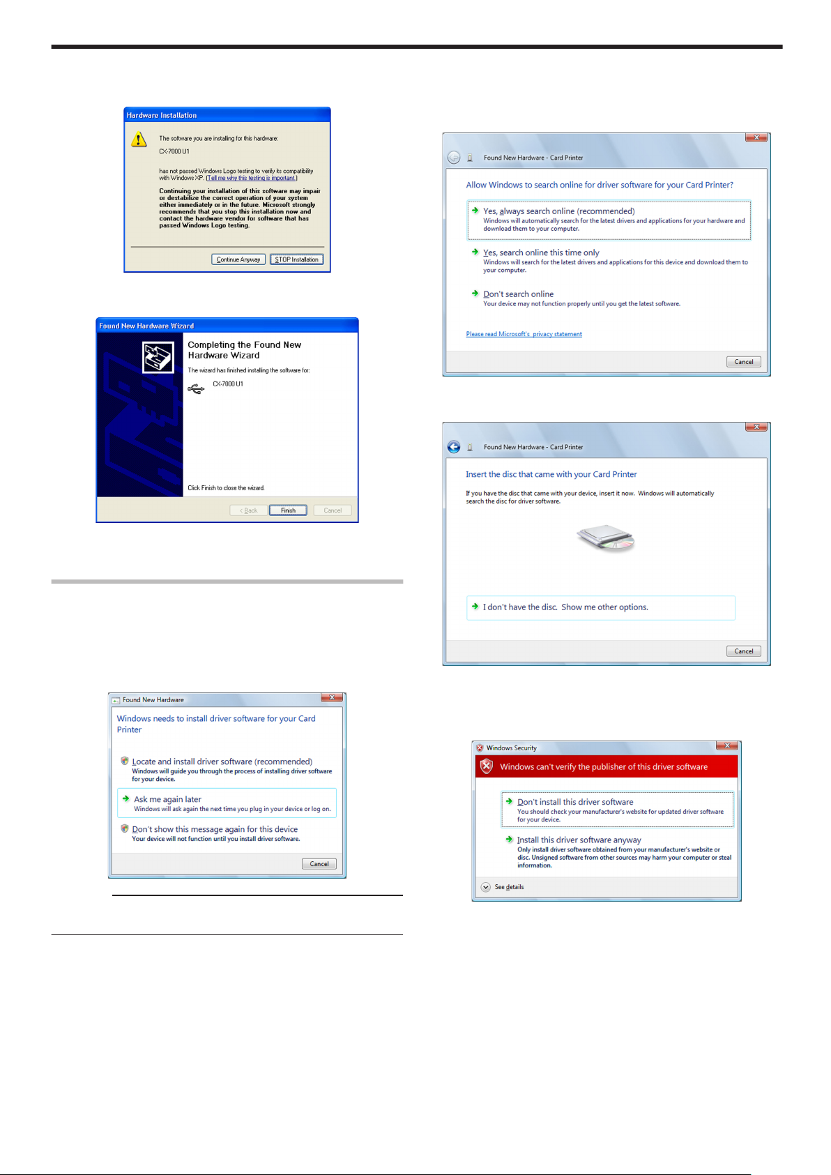
Setup
Select [Install the software automatically (Recommended)], and click
5
[Next]
v
A [Hardware Installation] screen appears.
.
Click [Continue Anyway]
6
v
A “Completing the Found New Hardware Wizard” screen appears.
Click [Locate and install driver software (Recommended)]
3
v
A [User Account Control] screen appears.
Click [Continue]
4
v
A [Found New Hardware] screen appears.
.
Click [Don’t search online]
5
v
A screen appears, prompting you to insert the disc.
.
Click [Finish]
7
v
Installation of the USB driver is complete.
Windows Vista
Start up Windows
1
Connect the computer and printer using the USB cable, and turn on
2
the power of the printer
v
The printer is automatically detected by the computer.
v
A [Found New Hardware] screen appears.
.
Cautions:
v
Connection is improper if this screen does not appear. Make sure
that the connection is properly established.
.
Set the supplied CD-ROM into the computer
6
v
The “SETUP.exe” automatic execution program in the CD-ROM is
not used. Exit this program.
v
A [Windows Security] screen appears.
.
77
Page 78
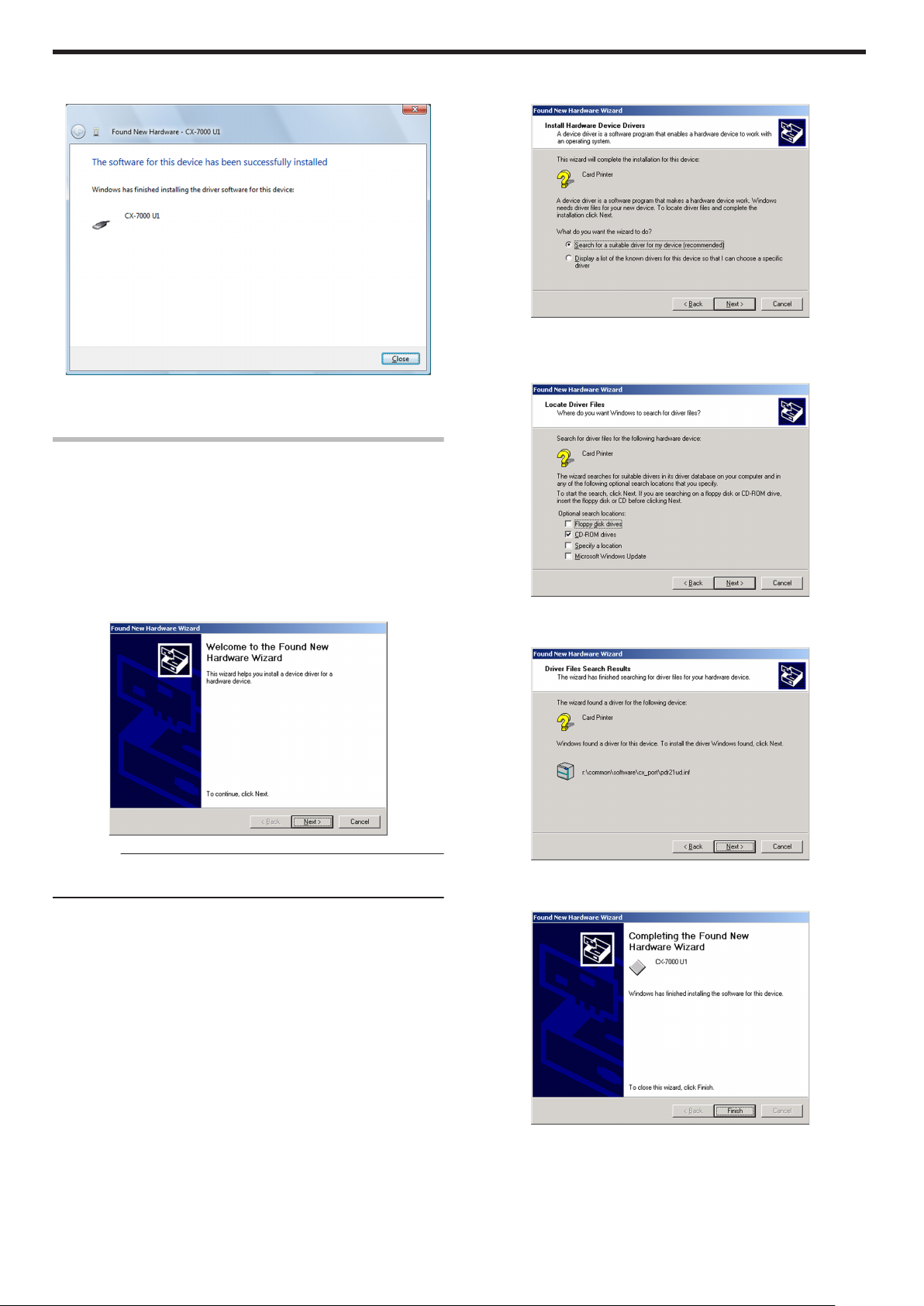
Setup
Click [Install this driver software anyway]
7
v
An installation complete screen appears.
.
Click [Close]
8
v
Installation of the USB driver is complete.
Windows 2000
Start up Windows
1
Set the supplied CD-ROM into the computer
2
v
The “SETUP.exe” automatic execution program in the CD-ROM is
not used. Exit this program.
Connect the computer and printer using the USB cable, and turn on
3
the power of the printer
v
The printer is automatically detected by the computer.
v
A [Found New Hardware Wizard] screen appears.
Click [Next]
4
v
A search method selection screen appears.
.
Select [Search for a suitable driver for my device (recommended)],
5
and click [Next]
v
A “Locate Driver Files” screen appears.
.
Select the [CD-ROM drives] checkbox, and click [Next]
6
v
A “Driver Files Search Results” screen appears.
.
Cautions:
v
Connection is improper if this screen does not appear. Make sure
that the connection is properly established.
78
.
Click [Next]
7
v
A “Completing the Found New Hardware Wizard” screen appears.
.
Click [Finish]
8
v
Installation of the USB driver is complete.
Page 79
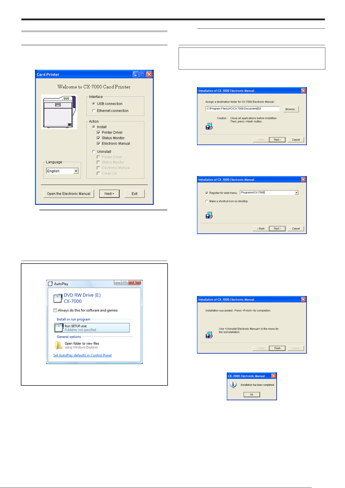
Electronic Manual
Installing the Electronic Manual
Start up Windows, and set the supplied CD-ROM into the computer
1
v
A card printer setup screen appears.
Setup
Memo:
v
You can select the [Printer Driver] and [Status Monitor] checkboxes
to install them simultaneously.
v
Clicking [Open the Electronic Manual] opens the Electronic
Manual.
v
Clicking [Exit] ends the installation.
Click [Next]
3
v
An Electronic Manual installation screen appears.
.
v
To change the displayed installation destination, click [Browse...] and
specify the destination folder.
Click [Next]
4
v
A selection screen for registering the Electronic Manual appears.
.
Memo:
v
If the CD-ROM drive of the computer is set to run automatically, the
installer will be executed automatically.
If the installer is not automatically initiated, double-click “SETUP.exe”
in the CD-ROM.
v
If you are not using the “SETUP.exe” automatic execution program
in the CD-ROM, start the installer for the Electronic Manual by
double-clicking the following file in the CD-ROM: “English\Document
\Manual\install.exe”.
m
Windows Vista
v
A [AutoPlay] screen appears.
.
v
Clicking [Run SETUP.exe] displays the [User Account Control]
screen.
v
Clicking [Allow] displays the card printer setup screen.
.
A Select the [Register for start menu] checkbox
v
To change the registration in the displayed Start menu, make a
selection from the [Register for start menu] list.
B Select the [Make a shortcut icon on desktop.] checkbox if
necessary
Click [Next]
5
v
Installation starts.
v
After installation is complete, an installation complete screen
appears.
.
Click [Finish]
6
v
An installation complete confirmation screen appears.
Select the [Electronic Manual] checkbox on the card printer setup
2
screen
A Select the language to use from the [Language] pull-down menu
v
Selecting [Japanese] switches the program to the Japanese
version.
v
Selecting [English] switches the program to the English version.
B Select [USB connection] or [Ethernet connection] from [Interface]
C Select [Install] under [Action], and select the [Electronic Manual]
checkbox
.
Click [OK]
7
v
Exits the installation program.
v
You can now open the Electronic Manual from [Start menu].
79
Page 80
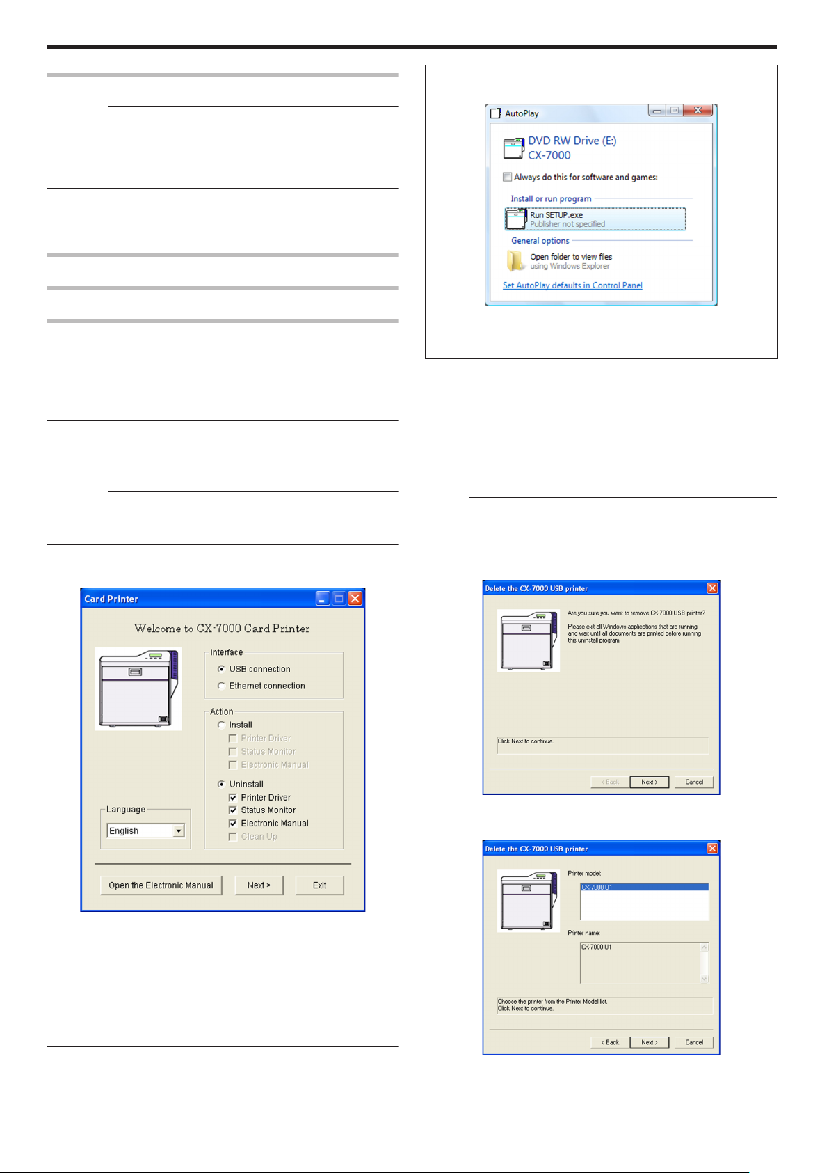
Setup
Uninstall
Cautions:
v
To uninstall the software, log into the system as an administrative
user (Administrators group).
v
A part of the illustrations in this Electronic Manual may not be
displayed depending on the computer’s environment. Skip the
procedures in this case.
v
"Printer Driver" (A page 80)
v
"Status Monitor" (A page 83)
v
"Electronic Manual" (A page 83)
Printer Driver
m
Windows Vista
v
A [AutoPlay] screen appears.
Uninstalling the Printer Driver
USB Connection
Cautions:
v
Do not execute “Uninstall” if there are applications that are currently
running.
v
If document printing is currently in progress, wait for all the jobs to
complete.
Start up Windows
1
Connect the computer and printer using the USB cable, and turn on
2
the power of the printer
Cautions:
v
Check to ensure that the printer connected via USB is recognized on
the computer. If the USB connection is not recognized, the USB
driver cannot be correctly deleted.
Set the supplied CD-ROM into the computer
3
v
A card printer setup screen appears.
.
v
Clicking [Run SETUP.exe] displays the [User Account Control]
screen.
v
Clicking [Allow] displays the card printer setup screen.
Select the [Printer Driver] checkbox on the card printer setup screen
4
A Select the language to use from the [Language] pull-down menu
v
Selecting [Japanese] switches the program to the Japanese
version.
v
Selecting [English] switches the program to the English version.
B Select [USB connection] from [Interface]
C Select [Uninstall] under [Action], and select the [Printer Driver]
checkbox
Memo:
v
You can select the [Status Monitor] and [Electronic Manual]
checkboxes to uninstall them simultaneously.
Click [Next]
5
v
A [Delete the CX-7000 USB printer] screen appears.
.
Memo:
v
If the CD-ROM drive of the computer is set to run automatically, the
installer will be executed automatically.
If the installer is not automatically initiated, double-click “SETUP.exe”
in the CD-ROM.
v
If you are not using the “SETUP.exe” automatic execution program
in the CD-ROM, start the uninstaller for the printer driver by doubleclicking the following file in the CD-ROM: “English\USB_Soft
\uninstall.exe”.
80
.
Check the details, followed by clicking [Next]
6
v
A printer model selection screen appears.
.
Page 81

Setup
Select the printer to uninstall, and click [Next]
7
v
An uninstall information confirmation screen appears.
.
Check the details, followed by clicking [Finish]
8
v
To change a printer, click [Back].
Cautions:
v
Uninstall the USB printer drivers accordingly for each printer unit
number.
v
An uninstallation complete screen appears.
Set the supplied CD-ROM into the computer
3
v
A card printer setup screen appears.
.
Memo:
v
If the CD-ROM drive of the computer is set to run automatically, the
installer will be executed automatically.
If the installer is not automatically initiated, double-click “SETUP.exe”
in the CD-ROM.
v
If you are not using the “SETUP.exe” automatic execution program
in the CD-ROM, start the uninstaller for the printer driver by doubleclicking the following file in the CD-ROM: “English\LAN_Soft
\uninstall.exe”.
.
Click [Finish]
9
v
Exits uninstallation.
Cautions:
v
To reinstall the printer driver, perform the installation procedures
after restarting Windows.
Ethernet (LAN) Connection
Cautions:
v
Do not execute “Uninstall” if there are applications that are currently
running.
v
If document printing is currently in progress, wait for all the jobs to
complete.
Start up Windows
1
Connect the computer and printer using a LAN cable, and turn on
2
the power of the printer
Cautions:
v
Do not connect a USB cable to the printer.
m
Windows Vista
v
A [AutoPlay] screen appears.
.
v
Clicking [Run SETUP.exe] displays the [User Account Control]
screen.
v
Clicking [Allow] displays the card printer setup screen.
Select the [Printer Driver] checkbox on the card printer setup screen
4
A Select the language to use from the [Language] pull-down menu
v
Selecting [Japanese] switches the program to the Japanese
version.
v
Selecting [English] switches the program to the English version.
B Select [Ethernet connection] from [Interface].
C Select [Uninstall] under [Action], and select the [Printer Driver]
checkbox
Memo:
v
You can select the [Status Monitor] and [Electronic Manual]
checkboxes to uninstall them simultaneously.
81
Page 82

Setup
Click [Next]
5
v
A [Delete the CX-7000 Ethernet printer] screen appears.
.
Check the details, followed by clicking [Next]
6
v
A printer model selection screen appears.
v
An uninstallation complete screen appears.
.
Click [Finish]
9
v
Exits uninstallation.
Cautions:
v
To reinstall the printer driver, perform the installation procedures
after restarting Windows.
.
Select the printer to uninstall, and click [Next]
7
v
An uninstall information confirmation screen appears.
.
Check the details, followed by clicking [Finish]
8
v
To change a printer, click [Back].
Cautions:
v
In the case where multiple Ethernet (LAN) printer drivers are
installed, the uninstaller deletes all of these printer drivers.
82
Page 83

Setup
Status Monitor
Uninstalling the Status Monitor
Cautions:
v
Do not execute “Uninstall” if there are applications that are currently
running.
v
If document printing is currently in progress, wait for all the jobs to
complete.
Exit the status monitor
1
Select [Uninstall Status Monitor] from [Start menu]
2
.
Memo:
v
If the [Register for start menu] checkbox is not selected during
installation of the status monitor, delete using [Add or Remove
Programs] in [Control Panel].
v
You can also perform uninstallation using the “SETUP.exe”
automatic execution program.
"SETUP.exe" (A page 75)
v
A status monitor deletion confirmation screen appears.
Electronic Manual
Uninstalling the Electronic Manual
Exit the Electronic Manual
1
Select [Uninstall Electronic Manual] from [Start menu]
2
.
Memo:
v
If the [Register for start menu] checkbox is not selected during
installation of the Electronic Manual, delete using [Add or Remove
Programs] in [Control Panel].
v
You can also perform uninstallation using the “SETUP.exe”
automatic execution program.
"SETUP.exe" (A page 79)
v
An Electronic Manual screen appears.
.
Click [OK]
3
v
An Electronic Manual deletion screen appears.
.
Click [OK]
3
v
Uninstallation starts, and a confirmation screen for deleting the
setting file appears.
.
Click [Yes]
4
v
Deletes the setting file for the status monitor. If you do not want to
delete it, click [No].
.
Click [Finish]
5
v
Exits uninstallation.
Click [Finish]
4
v
Exits uninstallation.
.
83
Page 84
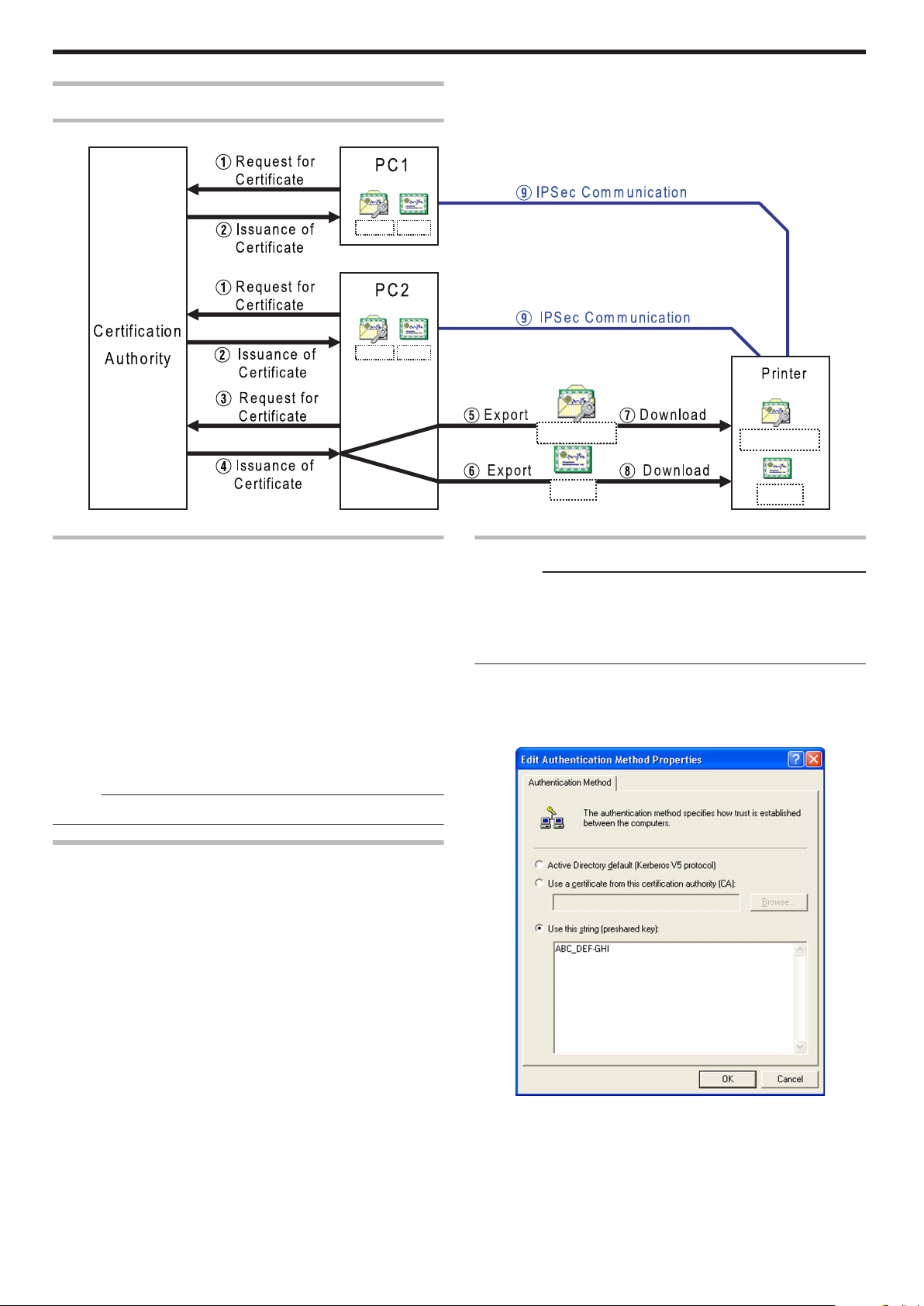
CA.cer
PC1.pfx
CA.cer
PC2.pfx
CA.cer
Printer01.pfx
CA.cer
Printer01.pfx
Setup
IPSec
Setting Procedures
.
Certificate Authentication
A Request the “PC Certificate” from the certification authority.
B The “PC Certificate” and “Certification Authority Certificate” are
issued by the certification authority. Install these on the PC.
C Request the “Printer Certificate” from the certification authority.
D The “Printer Certificate” and “Certification Authority Certificate”
are issued by the certification authority. Install these on the PC.
E Export the “Printer Certificate” and save it in a file.
F Export the “Certification Authority Certificate” and save it in a file.
G Connect the printer via USB, and download the “Printer
Certificate” using the status monitor.
H Connect the printer via USB, and download the “Certification
Authority Certificate” using the status monitor.
I Connect the printer via the network (Ethernet), and enable IPSec
(IP Security) on the PC to start IPSec communication.
Memo:
v
Consult the network administrator regarding A to D above.
Preshared Key Authentication
A Connect the printer via USB, and download the “Preshared Key
File” using the status monitor.
B Connect the printer via the network (Ethernet), and enable IPSec
(IP Security) on the PC to start IPSec communication.
Preshared Key File
Cautions:
v
Operate IPSec (IP Security) on Windows by following the
instructions of the network administrator for the location where the
printer is installed.
v
Manage the “Preshared Key File” according to the instructions of the
network administrator.
Start [IP Security Policy Management] under the MMC
1
(Management Console)
Open the [Edit Authentication Method Properties] of the policy for
2
which the preshared key is to be used
84
.
Page 85

Make use of applications such as Windows Notepad to create a
2x
3x
4x
5x
6x
7x
0
0 @ P p
1
1
A
Q
a
q
2
2
B
R
b
r
3
3
C
S
c
s
4
4
D
T
d
t
5
5
E
U
e
u
6
6
F
V
f
v
7
7
G
W
g
w
8
(
8
H
X
h
x
9
)
9 I Y I y
A
J
Z j z
B
K k
C
L l
D
- M m
E
. N n
F
O _ o
2x
3x
4x
5x
6x
7x
0
0 @ P p
1
1
A
Q
a
q
2
2
B
R
b
r
3
3
C
S
c
s
4
4
D
T
d
t
5
5
E
U
e
u
6
6
F
V
f
v
7
7
G
W
g
w
8
(
8
H
X
h
x
9
)
9 I Y I y
A
J
Z j z
B
K k
C
L l
D
- M m
E
. N n
F
O _ o
3
preshared key string, and save it as a file with the extension “.key”
.
v
After saving, this file will be downloaded as the “Preshared Key File”
when setting “Preshared Key Authentication” using the status
monitor.
v
ASCII characters that can be used for the preshared key of the
printer are as follows. The maximum length is 255 characters.
Printer Certificate File
Cautions:
v
Operate IPSec (IP Security) on Windows by following the
instructions of the network administrator for the location where the
printer is installed.
v
Manage the “Printer Certificate File” according to the instructions of
the network administrator.
v
There is an expiration date for the “Printer Certificate”. IPSec
communication may fail or may not be encrypted successfully if an
expired certificate is used.
Obtain the printer certificate from the certification authority, and
1
install it on the PC’s [Certificates (Local Computer)]
v
Obtain the printer certificate as an “exportable key”.
Start [Certificates (Local Computer)] under the MMC (Management
2
Console)
Open the Personal Store to export the printer certificate
3
Setup
.
Memo:
v
For procedures to set “Preshared Key Authentication” on the printer,
refer to the section of the Status Monitor Settings.
"File settings required for preshared key authentication" (A page 116)
.
v
The format is “PKCS#12”. Make sure that you specify a password.
The file is saved with the extension “.pfx”.
v
After saving, this file will be downloaded as the “Printer Certificate File”
when setting “Certificate Authentication” using the status monitor.
v
ASCII characters that can be used for the password of the printer certificate
of the printer are as follows. The maximum length is 255 characters.
.
85
Page 86

Setup
Memo:
v
For procedures to set “Certificate Authentication” on the printer, refer
to the section of the Status Monitor Settings.
"File settings required for certificate authentication" (A page 116)
Certification Authority Certificate File
Cautions:
v
Operate IPSec (IP Security) on Windows by following the
instructions of the network administrator for the location where the
printer is installed.
v
Manage the “Certification Authority Certificate File” according to the
instructions of the network administrator.
v
There is an expiration date for the “Certification Authority Certificate”.
IPSec communication may fail or may not be encrypted successfully
if an expired certificate is used.
Start [Certificates (Local Computer)] under the MMC (Management
1
Console)
Open the Certification Authorities Store, and export the same
2
“Certification Authority Certificate” as the printer certificate
.
v
The format is “DER encoded binary X509”. The file is saved with the
extension “.cer”.
v
After saving, this file will be downloaded as the “Certification
Authority Certificate File” when setting “Certificate Authentication”
using the status monitor.
Memo:
v
For procedures to set “Certificate Authentication” on the printer, refer
to the section of the Status Monitor Settings.
"File settings required for certificate authentication" (A page 116)
86
Page 87

Setup
Printer Driver Settings
m
"[Setup] Tab" (A page 87)
m
"[Print] Tab" (A page 87)
v
"[Printing area] Dialog Box" (A page 89)
v
"[Color] Dialog Box" (A page 90)
v
"[Look up table] Dialog Box" (A page 90)
v
"[Dither] Dialog Box" (A page 91)
v
"[UV ink] Dialog Box" (A page 91)
v
"[Printer settings] Dialog Box" (A page 94)
m
"[Encode] Tab" (A page 94)
m
"[Configuration] Tab" (A page 95)
m
"[Version] Tab" (A page 95)
Setting Example
"Example of Printer Setting" (A page 96)
"Example of Encode Setting" (A page 102)
[Setup] Tab
.
m
Orientation
Settings for printing orientation.
v
Portrait
Print with the shorter edge of the card on top.
v
Landscape
Print with the longer edge of the card on top.
m
Number of copies
Number of copies to print. Enter a number up to 999.
m
Settings for turns over the card
Settings for the card turn over operation.
v
Turns over the card after loading
Selecting this checkbox turns over the card after it is loaded.
m
[Load...] button
Loads setting information from a specified file.
m
[Save...] button
Saves setting information to a specified file.
[Print] Tab
.
m
Print
Executes printing.
Checked : Executes printing.
Unchecked : Printing is not executed, but encoding can be
performed.
m
Print on both sides
Prints both sides of the card.
Unchecked : Prints one side of the card.
Checked : Prints both sides of the card.
m
Print the back side first
Prints the image on the back side first when printing on both sides of
the card.
Unchecked : Starts printing from the image on the front side.
Checked : Starts printing from the image on the back side.
Memo:
The checkbox is enabled during double-sided printing.
m
Front side/Back side
Front side : Print settings for the front side of the card.
Back side : Print settings for the back side of the card.
m
Print mode
Ink list. Specify the ink to use for printing.
v
1. YMC:
Prints using the YMC ink.
v
2. K:
Prints using the Resin K ink.
v
3. YMCK:
Prints using the YMC ink and Resin K ink.
v
4. YMC+UV:
Prints using the YMC ink. Prints data set in the [UV ink] dialog
using the UV ink.
v
5. K+UV:
Prints using the Resin K ink. Prints data set in the [UV ink]
dialog using the UV ink.
v
6. YMCK+UV:
Prints using the YMC ink and Resin K ink. Prints data set in the
[UV ink] dialog using the UV ink.
Cautions:
v
Print error occurs if an ink that is not mounted to the printer is
selected.
87
Page 88

Setup
m
Using of Resin K ink
For specifying the component to print using the Resin K ink.
v
Extraction
Prints the black color component on each page using the Resin K
ink.
Only text:Prints only the black color text using the Resin K
All
With YMC
ink
v
Page split
Prints all components on a specific page using the Resin K ink.
v
Security erase
Enables the Resin K security erase feature.
m
Rotate by 180
Prints the page upside down.
m
Enables the printing area
Enables the printing area of the peel-off ink and the area that is not
printed by all (YMCKUV) inks. Set a value in the [Printing area]
dialog.
Unchecked : Prints with the printing area disabled.
Checked : Prints with the preset printing area enabled.
v
[Settings...] button
Opens the [Printing area] dialog.
"[Printing area] Dialog Box" (A page 89)
m
Enable the color adjustment
Adjusts the color. Set a value in the [Color] dialog.
Unchecked : Prints with color adjustment disabled.
Checked : Prints with the predetermined color adjustment
v
[Settings...] button
Opens the [Color] dialog.
"[Color] Dialog Box" (A page 90)
m
Enable the look-up table
Uses the look-up table. Set a value in the [Look up table] dialog.
Unchecked : Prints with the look-up table disabled.
Checked : Prints with the preset look-up table enabled.
v
[Settings...] button
Opens the [Look up table] dialog.
"[Look up table] Dialog Box" (A page 90)
m
[Dither...] button
For specifying settings related to dithering.
Set a value in the [Dither] dialog.
"[Dither] Dialog Box" (A page 91)
Memo:
v
Selecting [2.K], [3.YMCK], [5.K+UV] or [6.YMCK+UV] in [Print
mode] enables the [Dither...] button.
ink.
Prints all black color components using the Resin
:
K ink.
Prints the background of the specified black color
:
component using the YMC ink.
settings enabled.
m
[UV ink...] button
For specifying settings related to UV ink print data.
Set a value in the [UV ink] dialog.
"[UV ink] Dialog Box" (A page 91)
Memo:
v
Selecting [4.YMC+UV], [5.K+UV] or [6.YMCK+UV] in [Print mode]
enables the [UV ink...] button.
m
Enable the printer settings
Enables the [Printer settings] dialog settings. Set the item in the
[Printer settings] dialog.
Unchecked : Prints with the printer settings disabled.
Checked : Prints with the printer settings enabled.
Memo:
If the [Printer settings] checkbox in the [Configuration] tab is
selected, the Enable the printer settings checkbox will also be
automatically selected.
"[Configuration] Tab" (A page 95)
v
[Settings...] button
Opens the [Printer settings] dialog.
"[Printer settings] Dialog Box" (A page 94)
88
Page 89

[Printing area] Dialog Box
Direction of card
movement
H
W
Y=0
X=0 About X=87.5
About Y=56.0
E1
E2
E3
>
=
>
=
E1
E2
E3
Settings related to the printing area using the peel-off ink or areas not
to be printed using all YMCKUV inks.
m
[Add] button
Registers the input data. You can enter up to 8 input data.
m
[Delete] button
Deletes the information selected in the list.
m
[Delete All] button
Deletes all registered information.
m
Peeloff ink energy
Print density of the peel-off ink.
Do not alter the following values.
v
E1: 225
v
E2: 160
v
E3: 160
m
Setting values
The following requirements must be satisfied.
Setup
.
.
m
Rectangular region
Printing area information.
m
X
X coordinate that indicates the start of the area. (Unit: mm).
m
Y
Y coordinate that indicates the start of the area. (Unit: mm).
m
W
Width of the printing area. (Unit: mm).
m
H
Height of the printing area. (Unit: mm).
m
Ink
Ink valid for the printing area.
The following values are recommended when peel-off printing is
.
performed on the ISO magnetic stripe area of the card.
X
Y W H Ink Side
0 0 87.46 17.86 1. Peeloff 1. Front
0 0 87.46 21.42 2. YMCK 1. Front
Cautions:
v
The input value of the textbox may differ from the value of the
“Printing area information” portion by an accidental error in
calculation.
Memo:
v
The printing start position displayed on the application software may
not coincide with the X=0, Y=0 position above.
About 1 mm from the edge of the image is not printed on the card.
"The edge of the image is not printed" (A page 123)
v
1. Peeloff:
Area for printing using the peel-off ink.
v
2. YMCK:
Area not to be printed using all YMCKUV inks.
m
Side
The side of the card for which the printing area is valid.
v
1. Front:
Front side
v
2. Back:
Back side
89
Page 90
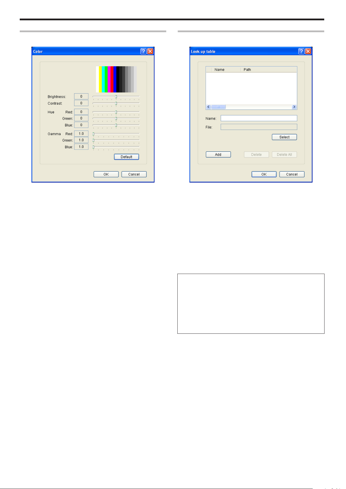
Setup
[Color] Dialog Box
Settings related to color adjustment.
.
m
Brightness
Brightness level.
m
Contrast
Contrast level.
m
Hue
Hue level.
m
Gamma
Gamma level.
m
[Default] button
Restores the settings to the default values.
[Look up table] Dialog Box
Settings related to the look-up table.
.
m
Name
Registered name of the look-up table file. You can enter a name up to
30 characters.
m
File
Look-up table file. Click the [Select] button to select a file.
m
[Add] button
Registers the input data. You can enter up to 16 input data.
m
[Delete]
Deletes the information selected in the list.
m
[Delete All]
Deletes all registered information.
m
File structure of the look-up table
v
Data format of the file is CSV (Comma Separated Values).
v
Delimiter character is comma (ASCII character code: 0x2c) or LF
(Line Feed = ASCII character code: 0x0A).
v
There is a total of 1024 fields. This is comprised of four planes,
each containing 256 fields.
v
The planes are arranged in the order of yellow, magenta, cyan,
and black colors.
v
The value of each field ranges between 0 and 255.
90
Page 91

Setup
[Dither] Dialog Box
Settings related to dithering.
.
Cautions:
v
This setting is enabled only when the [Print mode] item inside the
[Print] tab is specified as [2.K] or [5.K+UV], and when the [Page split]
is selected for [Using of Resin K ink].
m
Image adjustment
Image adjustment value.
v
Dark:
Darkens the printed image after dithering.
v
0:
Default value.
v
Light:
Brightens the printed image after dithering.
m
[Default] button
Restores the settings to the default values.
[UV ink] Dialog Box
Settings related to the data to be printed using the UV ink. Settings for
the [MAC address position] and [Number of panels using the retransfer
film] can be specified in this section.
.
Cautions:
v
This setting is enabled only when the [Print mode] item of the [Print]
tab is specified as [4.YMC+UV], [5.K+UV] or [6.YMCK+UV].
m
Front side/Back side
Front side: Settings for the front side of the card.
Back side: Settings for the back side of the card.
m
Extraction
Prints the following color component on each page using the UV ink.
"Priority of printing data" (A page 92)
v
Text
Prints the text of a specified color using the UV ink with maximum
density.
White and black colors cannot be selected.
v
File
Prints the image files registered in the [File information] list using
the UV ink.
m
Page split
Prints all components on a specific page using the UV ink with 256
gradation. Page split is divided in the order of YMC ink, Resin K ink
and UV ink.
"Page number for the printed document and page split settings" (A
page 92)
m
No printing color
Selected color is not printed using the UV ink.
Memo:
v
The background of the UV ink image is specified here. Paint the
background of the image with a specific color such as by using a
graphic software.
Select the background color carefully, as any color in the image
that is the same as the background color will not be printed.
v
The color selected here does not influence the colors specified in
[Extraction]-[Text]. Even when the same color is selected, the text
in that color will be printed.
m
MAC address position
The network (Ethernet) MAC address of the printer is printed at the
following specified position using the UV ink.
A Upper Right:
Upper right position
B Lower Left:
Lower left position
"MAC Address Position" (A page 92)
91
Page 92

1234-5678-90AB
1234-5678-90AB
A
C
B
D
Setup
m
File information
Settings related to the image file to be printed using the UV ink.
Memo:
v
This setting is enabled when [Extraction]-[File] for the front side or
back side is specified.
m
Name
Registered name of the image file. You can enter a name up to 30
characters.
m
File
Image file. Click the [Select] button to select a file.
"Windows Bitmap File Format" (A page 93)
m
X
X coordinate where printing of the image file starts. (Unit: mm).
When [Orientation] inside the [Setup] tab is set to [Landscape], the
value is 0.00 to 87.4. When [Portrait] is set, the value is 0.00 to 55.9.
Data outside the printing area is not printed.
m
Y
Y coordinate where printing of the image file starts. (Unit: mm).
When [Orientation] inside the [Setup] tab is set to [Landscape], the
value is 0.00 to 55.9. When [Portrait] is set, the value is 0.00 to 87.4.
Data outside the printing area is not printed.
m
Side
The side of the card for which the printing area is valid.
Page Number for the Printed Document and Page Split
Settings
.
v
When [Page split] is not set, UV ink data is extracted from the YMC
ink data, or the UV ink image file is used.
v
1. Front:
Front side
v
2. Back:
Back side
m
[Add] button
Registers the input data. You can enter up to 8 input data.
m
[Delete] button
Deletes the information selected in the list.
m
[Delete All] button
Deletes all registered information.
m
Number of panels using the retransfer film
Number of retransfer film panels to be used.
v
Auto:
Automatically prints one panel of the retransfer film when the data
of other ink types does not overlap with the UV ink printing
position.
v
1 panel:
Always prints one panel of the retransfer film. When the data of
other ink types overlaps with the UV ink printing position, the data
of the ink types will be adjusted.
v
2 panels:
Always prints two panels of the retransfer film.
"Number of retransfer film panels during printing" (A page 93)
Priority of printing data
v
An extracted text has a higher priority than an image file, and is
always printed on the top.
v
The image files are processed in the order of registration. When
there is overlap in the printing areas, the older data will be
overwritten by the data of the image file that is registered later.
MAC Address Position
v
In the case of UV ink printing, the printer always prints the MAC
address.
v
The printing position of the MAC address can be set separately for
the front and back sides using the printer driver. The two positions
below can be selected.
m
[Landscape] Orientation
.
A MAC address printing position when [Upper Right] is selected
B MAC address printing position when [Lower Left] is selected
C (X=0, Y=0)
D (X = approx. 87.5 mm, Y = approx. 56.0 mm), (X = 1035 pixel,
Y = 663 pixel)
MAC
Address
Printing
Position
AUpper
Right
BLower
Left
StartingXStartingYWidth Height
64.69 mm 1.52 mm 19.47
mm
764 pixel 18 pixel 230
2.88
mm
34 pixel
pixel
3.56 mm 51.73 mm 19.47
mm
42 pixel 611 pixel 230
2.88
mm
34 pixel
pixel
92
Page 93
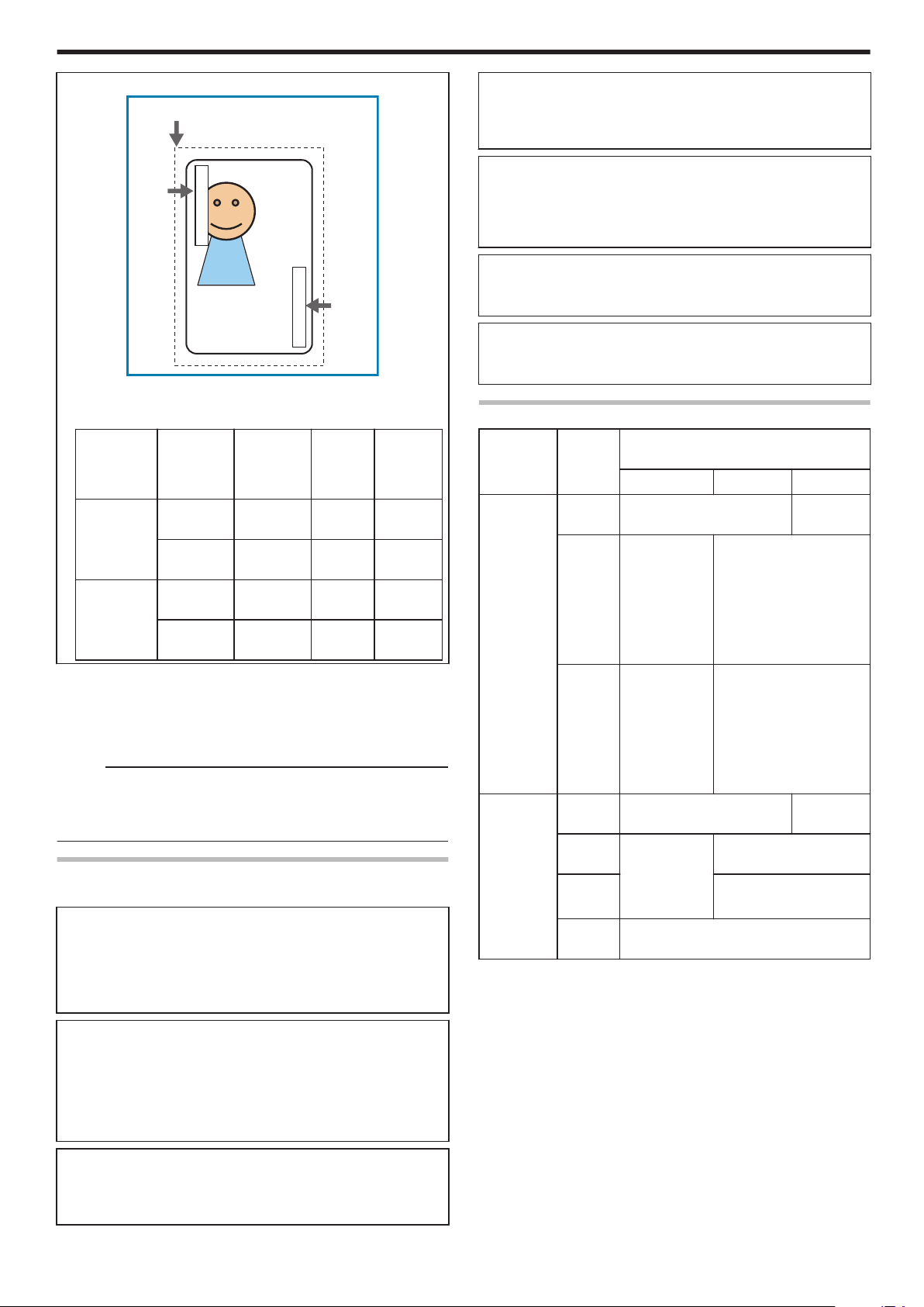
B
C
A
1234-5678-90AB
1234-5678-90AB
Setup
m
[Portrait] Orientation
.
A MAC address printing position when [Upper Right] is selected
B MAC address printing position when [Lower Left] is selected
C (X=0, Y=0)
MAC
StartingXStartingYWidth Height
Address
Printing
Position
AUpper
Right
51.82 mm 64.69 mm 2.88
mm
612 pixel 764 pixel 34 pixel 230
BLower
Left
1.61 mm 3.56 mm 2.88
mm
19 pixel 42 pixel 34 pixel 230
v
The above printing position setting for the MAC address is always
effective regardless of the printer unit settings.
The above measurements show the relative position from the
starting point of the image. As such, the actual printing position on
the card may be slightly different from the abovementioned
measurements.
Memo:
v
The printing start position displayed on the application software may
not coincide with the X=0, Y=0 position above.
About 1 mm from the edge of the image is not printed on the card.
"The edge of the image is not printed" (A page 123)
Windows Bitmap File Format
The following Windows bitmap file formats (*.BMP) are supported.
m
Monochrome/Black & white
v
Bit(s): 1
Normally, white color is printed using the UV ink with maximum
density.
When white color is selected in [No printing color], black color is
printed using the UV ink with maximum density.
m
2 colors
v
Bit(s): 1
Prints using the UV ink with 256 gradation in accordance with the
color palette.
If any of the colors in the color palette is specified in [No printing
color], other colors that are not specified are printed using the UV ink
with maximum density.
19.47
mm
pixel
19.47
mm
pixel
m
256 colors
v
Bit(s): 8
Prints using the UV ink with 256 gradation in accordance with the
color palette.
m
32768 colors
v
Bit(s): 15
Prints using the UV ink with 256 gradation.
Only the “(MSB) GGGBBBBB-XRRRRRGG(LSB)” format is
supported.
m
24 bits
v
Bit(s): 24
Prints using the UV ink with 256 gradation.
m
32 bits
v
Bit(s): 32
Prints using the UV ink with 256 gradation.
Number of retransfer film panels during printing
Printing
Data
Printing
None Print in 1 panels Print in 2
data that
overlaps
with the UV
ink data
YMC
Ink
outside the
MAC
address
printing
area
K
Ink
Printing
None Print in 1 panels Print in 2
data inside
the MAC
address
area
YMC
Ink
K
Ink
UV
Ink
The target printing data is compared in units of pixels to determine
whether there is any overlap.
Priority is given to the “Print in 2 panels” setting.
[Number of panels using the retransfer
film] Setting
1 Panel Auto 2 Panels
panels
Print in 1
Print in 2 panels
panels
* The YMC ink
is not printed
at areas
where it
overlaps with
the UV ink.
Print in 1
Print in 2 panels
panels
* The UV ink
is not printed
at areas
where it
overlaps with
the K ink.
panels
Print in 1
Print in 2 panels
panels
* Does not
print using the
Print in 2 panels
YMCK ink.
Prints the MAC address only
m
16 colors
v
Bit(s): 4
Prints using the UV ink with 256 gradation in accordance with the
color palette.
93
Page 94

Setup
[Printer settings] Dialog Box
Settings related to the printer.
Select the checkbox for the setting item to enable, followed by
specifying a value. Doing so prints the data using the set values.
When the setting is not enabled, data is printed using the preset values
of the printer unit.
.
m
YMC ink print level
Print density of the YMC ink.
Use the [+] values to increase, and [-] values to decrease the density.
m
Resin K ink print level
Print density of the Resin K ink.
Use the [+] values to increase, and [-] values to decrease the density.
m
UV ink print level
Print density of the UV ink.
Use the [+] values to increase, and [-] values to decrease the density.
m
Peel off ink print level
Print density of the peel-off ink.
Use the [+] values to increase, and [-] values to decrease the density.
m
Resin K ink print mode
Print quality of the Resin K ink.
Selecting [Fine] enhances the printing quality, but slows down the
printing speed.
m
MG peel mode
When a magnetic encoder unit is installed, selecting [MG Stripe]
optimizes the peeling operation of retransfer films for magnetic stripe
cards.
m
Standby mode
Specify a position when a laminator is connected.
This is used for setting the standby position of the card during doublesided printing until the laminator is ready. [Front wait] is selected by
default.
m
Back side cooling
This setting is only valid during double-sided printing.
Setting this item may help to reduce card bend during double-sided
printing. However, the printing time may also be affected.
m
Retransfer
Settings related to retransfer. Click on the corresponding square to
change the value.
Setting a value toward the top right end increases the transfer force.
However, the stronger heat also increases the deformation of the card.
v
Temperature
Temperature of the retransfer heating roller.
v
Speed
Retransfer speed.
v
UV speed
Setting for printing the retransfer film in two panels when UV ink is
used.
It is used to set the speed of the retransfer heating roller during
retransfer of the UV ink.
This setting helps to increase the retransfer speed without affecting
the quality of the UV print.
m
Bend remedy
Settings related to bend remedy.
Click on the corresponding square to change the value.
Setting a value toward the top right end increases the bend remedy
force. However, the stronger heat may have a greater impact on the
card.
To disable bend remedy, select the [Disable] button.
v
Temperature
Temperature of the bend remedy heating roller.
v
Speed
Bend remedy speed.
Cautions:
v
The optimal retransfer and bend remedy settings vary according to
the card type as well as environment in which the printer is used.
Adjust the setting according to the actual environment.
v
If the retransfer or bend remedy settings are different from the preset
temperature of the printer, it may take a while before printing starts.
v
There is only one standard retransfer temperature. Altering the
retransfer temperature on one side changes the temperature on the
other side.
v
Bend remedy is effective when printing on only one side. Setting
bend remedy to a high temperature during double-sided printing may
cause the card to deform significantly.
As such, select the [Disable] button during double-sided printing.
v
When bend remedy is disabled using the [Disable] button, the speed
is automatically set to the maximum value of [+2].
v
The stronger the bend remedy force, the less glossy the surface of
the remedy side will be.
[Encode] Tab
94
.
Page 95

Setup
m
IC
m
Non-contact IC encode
Allows writing of data to a non-contact IC.
m
Contact IC encode
Allows writing of data to a contact IC.
m
Turns over the card after IC encoding
Turns over the card after writing data to the non-contact/contact
IC.
m
Magnetic
m
Magnetic encode
Allows writing of data to the magnetic stripe.
m
Turns over the card after MG encoding
Turns over the card after writing data to the magnetic stripe.
m
Write Retry
For setting the maximum number of retries when writing to or
reading of the magnetic stripe fails.
When the [Default] is selected, the retry counter uses the preset
value of the printer.
m
Coercivity
Coercivity of the magnetic stripe card.
When the [Default] is selected, the coercivity uses the preset value
of the printer.
m
Starts from magnetic encoding
Unchecked : Encodes in the ICNMagnetic sequence.
Checked : Encodes in the MagneticNIC sequence.
m
Prints after encoding
Unchecked : Starts printing while encoding is in progress.
Checked : Starts printing after encoding is complete.
m
Optional configuration
For specifying whether the options are installed.
m
Turn over unit
m
Bend remedy unit
m
Non-contact IC encoder
m
ISO Contact IC encoder
m
JIS Contact IC encoder
m
ISO Magnetic encoder
m
JIS Magnetic encoder
m
Laminator
m
Enable the settings
Permits or forbids the [Enable the printer settings] functions in the
[Print] tab.
m
Printer settings
Unchecked : Forbids the [Enable the printer settings] functions in
the [Print] tab.
Checked : Permits the [Enable the printer settings] functions in
the [Print] tab.
"Enable the printer settings" (A page 88)
Cautions:
v
When a user logs in with administrator authority (Administrators
group), the [Configuration] settings can be specified.
If a user logs in without administrator authority, the [Configuration]
settings appear in the read-only mode, and they cannot be specified.
[Version] Tab
Displays the version and copyright information.
[Configuration] Tab
.
Memo:
v
These settings can be altered only when the user logs into the
printer driver settings page with administrator authority
(Administrators group).
This tab is displayed in the read-only mode when a user without
administrator authority logs in.
.
95
Page 96
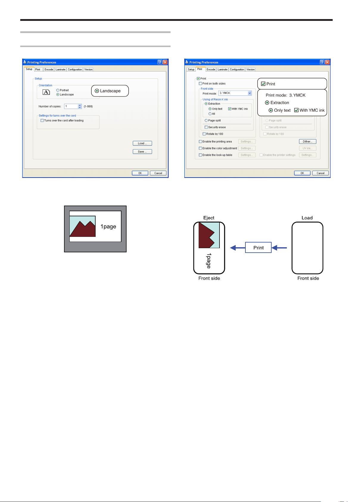
Setup
Example of Printer Setting
Single-sided Printing (Landscape)
. .
m
Application software
v
Graphic: colored
v
Text: black
m
Printer
v
Graphic: YMC ink
v
Text: YMC ink + Resin K ink
.
.
96
Page 97

Single-sided Printing (Portrait)
. .
Setup
m
Application software
v
Graphic: colored
v
Text: black
m
Printer
v
Graphic: YMC ink
v
Text: Resin K ink
.
.
97
Page 98

Setup
Double-sided Printing (Default)
. .
m
Application software
v
Graphic: colored
v
Text: black
m
Printer
v
Graphic: YMC ink
v
Text: YMC ink + Resin K ink
.
.
98
Page 99

Double-sided Printing (Single-side Lamination)
. .
Setup
m
Application software
Page 1
v
Graphic: colored
v
Text: colored
Page 2
v
Graphic: black
v
Text: black
m
Printer
Front side
v
Graphic: YMC ink
v
Text: YMC ink
Back side
v
Graphic: Resin K ink
v
Text: Resin K ink
.
.
Memo:
v
If page 2 is set as colored, printing is performed using the Resin K
ink after dithering is complete.
"[Dither] Dialog Box" (A page 91)
99
Page 100

Setup
Single-sided UV Printing
Clicking [UV Ink...] opens the [UV Ink] dialog box.
.
m
Application software
v
Graphic: colored
v
Text: black
.
m
Printer
v
Graphic: YMC ink
v
Text: YMC ink + Resin K ink
v
UV1.bmp: UV ink
v
MAC address: UV ink
.
.
100
 Loading...