

Page 1
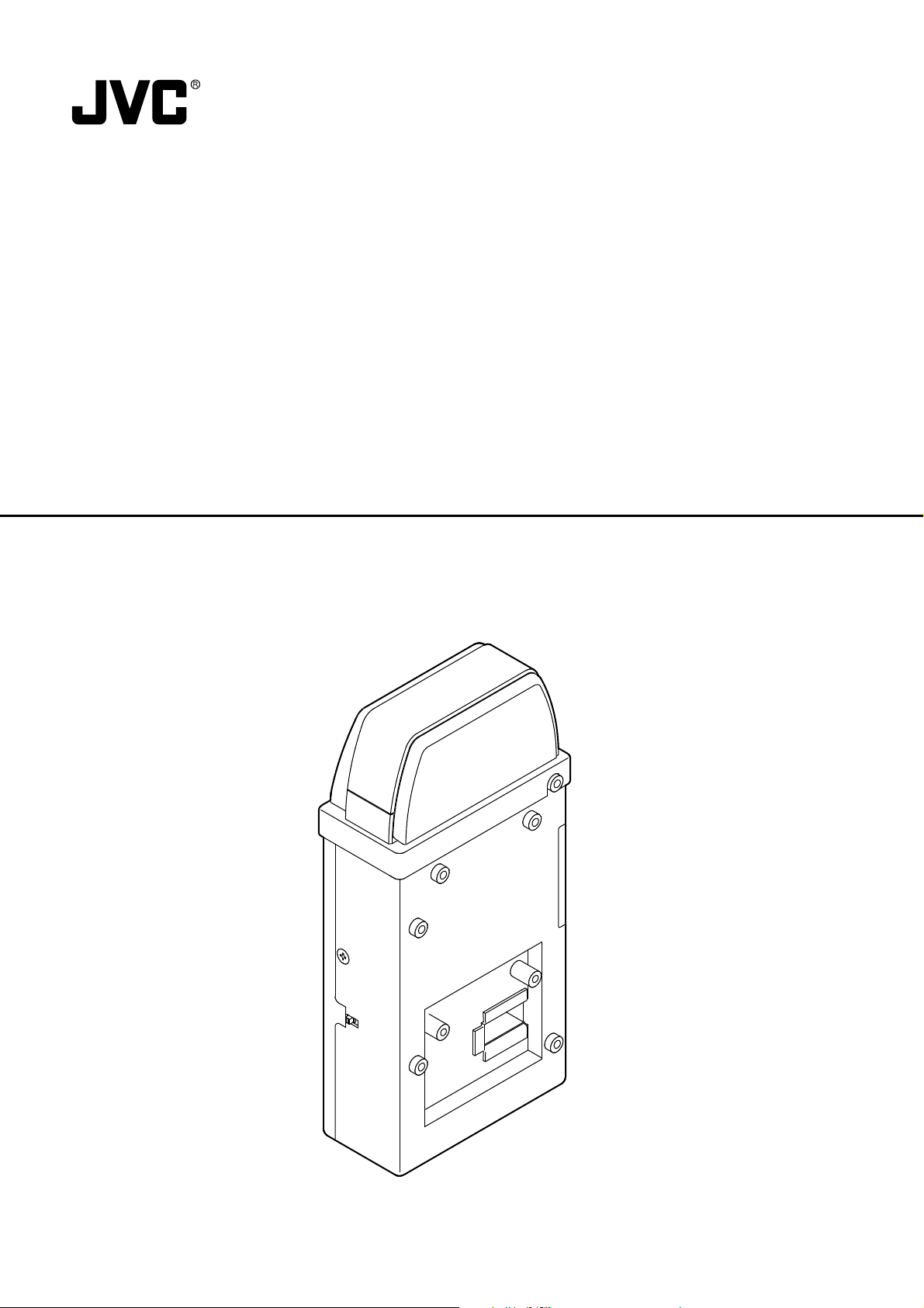
NETWORK PACK
KA-DV5000
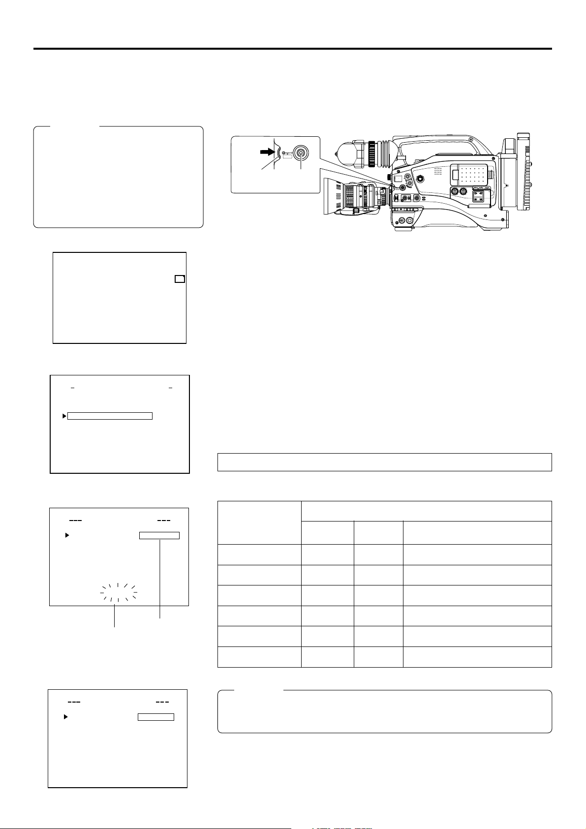
KA-DV5000
NETWORK PACK
POWER
SUPPLY
O
N
O
FF
User’s Guide
NETWORK
PACK
KA-DV5000
LST0103-001B
Page 2

When attaching Network Pack KA-DV5000 to DV Camcorder GY-DV5000, network related menus are added to the GY-DV5000 menu
screen.
This User’s Guide explains settings for the network related menus, operation for recording streaming data to a CF (Compact Flash)
memory card and operation for sending streaming data using a LAN card. When a LAN card is connected, menu screen settings for the
Network Pack and GY-DV5000 can be operated from your PC.
Contents
Introduction
Inserting/removing CF memory card/LAN card ............................................................................................................................... 3
LCD screen/viewfinder screen .........................................................................................................................................................4
When inputting the 44.1 kHz sampling audio siganl ........................................................................................................................ 4
Menu screen
Menu screen structure ..................................................................................................................................................................... 5
NETWORK PACK CONFIG menu screen items ............................................................................................................................... 6
Setting the NETWORK PACK CONFIG menu screen ....................................................................................................................... 8
Returning the NETWORK PACK CONFIG menu screen to factory settings .................................................................................... 9
Network settings
Setting the NETWORK MAIN SETUP menu screen........................................................................................................................ 10
NETWORK MAIN SETUP menu screen items ................................................................................................................................ 11
Setting user names and passwords ............................................................................................................................................... 13
Making network related settings .................................................................................................................................................... 14
Detailed IP settings (LAN) .............................................................................................................................................................. 15
Detailed network settings (WLAN) ................................................................................................................................................. 16
Recording on a CF card
Formatting a CF memory card ....................................................................................................................................................... 18
CF memory recording time............................................................................................................................................................. 18
Recording video on a DV cassette tape and CF memory card ..................................................................................................... 19
Recording video on a CF memory card only ................................................................................................................................. 20
Recording playback signals of a DV cassette tape on a CF memory card ................................................................................... 21
Deleting all clip files on a CF memory card ................................................................................................................................... 22
Movie clips
Playing back video/audio recorded on a CF memory card ........................................................................................................... 23
Protecting a clip file on a CF memory card .................................................................................................................................... 25
Deleting a clip file on a CF memory card ....................................................................................................................................... 26
Playing back CF memory card clips on your PC ........................................................................................................................... 27
LAN card
Sending video using LAN card while recording on a DV cassette tape ........................................................................................ 28
Sending video using a LAN card (no DV cassette tape recording)............................................................................................... 29
Sending playback signals of a DV cassette tape using a LAN card ............................................................................................. 30
Network pack setup
Controlling GY-DV5000/KA-DV5000 via LAN a card ...................................................................................................................... 31
NETWORK SETUP screen .............................................................................................................................................................. 32
PORT SETUP screen ......................................................................................................................................................................34
CAM & VTR CONTROL screen ...................................................................................................................................................... 35
ENCODE PARAMETERS screen .................................................................................................................................................... 37
Streamcapture screen (Playing back video/audio using a PC and saving to file) ......................................................................... 38
Others
TOP PAGE can be customized ...................................................................................................................................................... 42
Connecting Windows Media player ............................................................................................................................................... 43
Connecting Quick Time player ....................................................................................................................................................... 44
About updating the network pack ..................................................................................................................................................45
Troubleshooting ..............................................................................................................................................................................46
Checking communication/connection ............................................................................................................................................ 48
Terminology .................................................................................................................................................................................... 49
Characters and symbols used in this instruction book
Caution Cautionary notes concerning operation of the unit
Memo Reference such as restrictions of features, etc.
☞ Reference page or item
* In general, the names of products manufactured by other companies and mentioned in these
instructions are trademarks or registered trademarks of these companies.
Symbols like ™, ©, ®, etc., are not used in these instructions.
2
Page 3
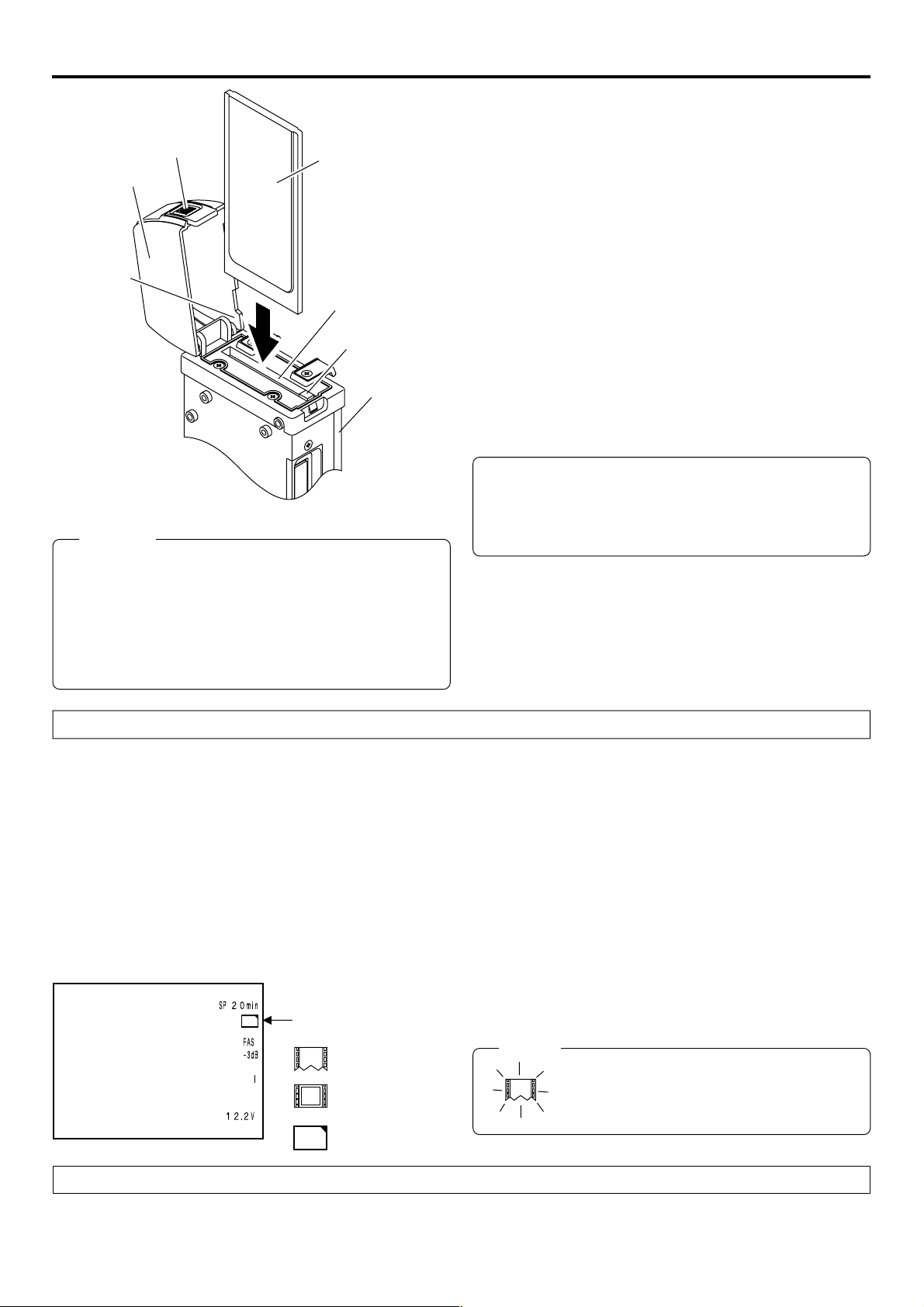
Introduction Inserting/removing CF memory card/LAN card
● The KA-DV5000 accepts the following cards for which operation has
been confirmed: (As of August 2002)
Operating voltage 3.3 V
Lock release button
Cover
Section A
CF memory card or
LAN card
Card slot
EJECT button
KA-DV5000
Caution
● Make sure the power of GY-DV5000 is off when inserting/
removing a CF memory card/LAN card. Inserting/removing
a card with the unit power on may damage the data storage
section of the CF memory card or the card itself.
● Do not use the wireless LAN card continuously for more
than 48 hours.
Current consumption Max. 500 mA
• Wired LAN-card
US: EA2900-117 (Revision C) (Name of manufacturer: Socket
Communications, Inc)
Europe: EA2903-162 (Revision C) (Name of manufacturer: Socket
Communications, Inc)
Asia: EA2906-194 (Revision C) (Name of manufacturer: Socket
Communications, Inc)
* Revision indicated on the upper right of package production label.
• Wireless LAN-card
TEW-201PC
TEW-202CF
TEW-PC16 (firmware version 0.8.3 or later) (Name of manufacturer:
TRENDware)
WCF11 (Name of manufacturer: LINKSYS)
AIR-PCM350
(Name of manufacture: Cisco Systems)
FCCID: LDK102040
• CF (Compact Flash) card
SDCFB-16 ~ SDCFB-256 (Name of manufacturer: SanDisk)
*1: Use PCMCIA card TYPE 1 or TYPE 2 adapter
*2: Use PCMCIA card TYPE 2 adapter
*1
*1
*1
*2
*1
For the latest operational check card, visit the website below
or contact your JVC dealer.
http://www.jvc-victor.co.jp/english/pro/prodv/
Inserting card
1.
Turn off the GY-DV5000 power.
2.
Press and hold the lock release button and open the cover.
3.
Insert a card into the KA-DV5000 card slot. Then, close the cover.
● The cover may not close depending on the wired LAN card or the card shape. In this case, remove the cover by pressing section
A and pulling on the cover.
4.
Turn on the GY-DV5000 power.
5.
Turn on the KA-DV5000 power.
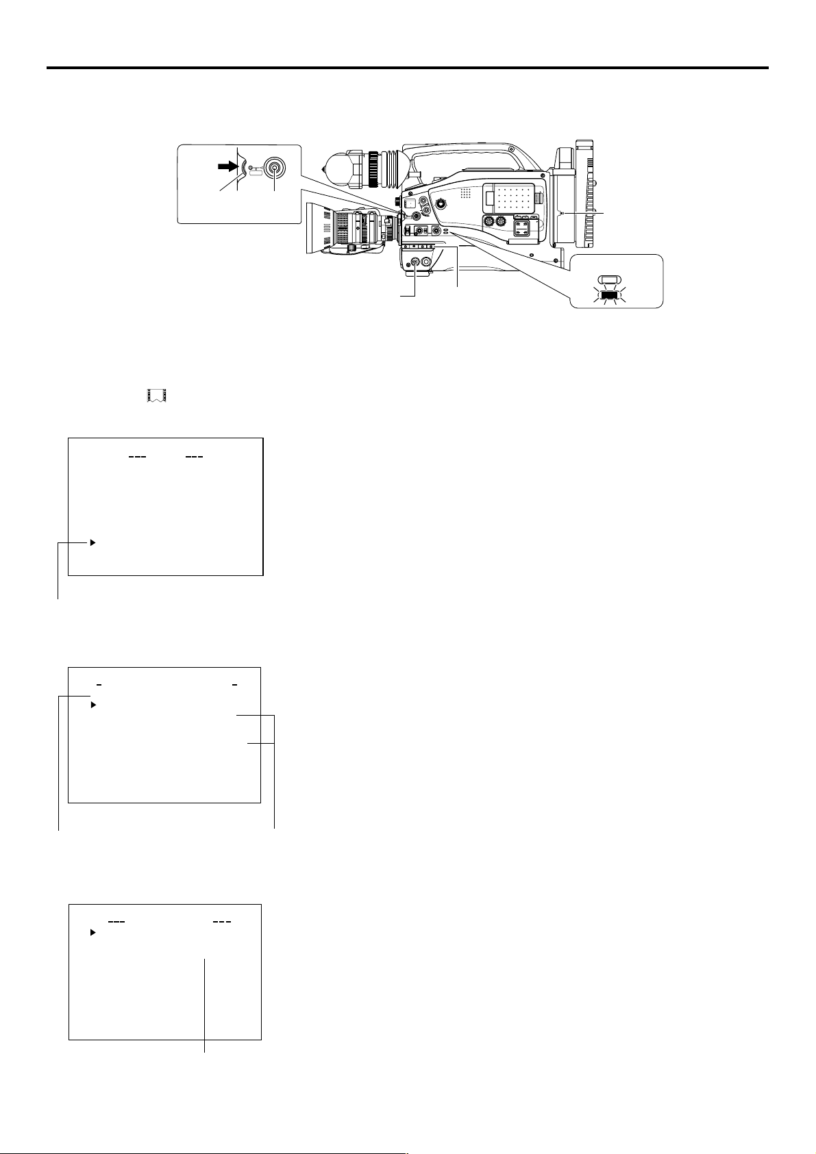
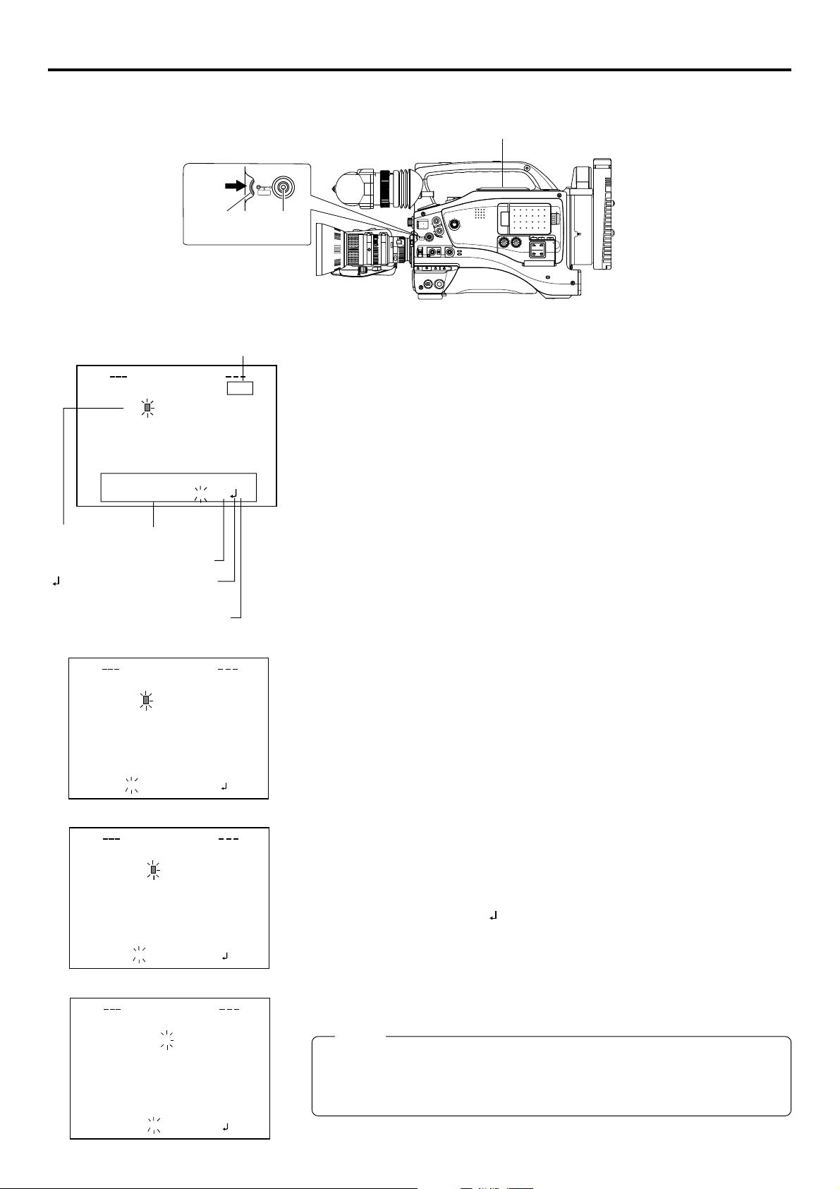
LCD screen
C
F
Card status display
: No card
: LAN card
e
: CF memory card
C
F
● Card status according to the inserted card type is displayed on
the LCD screen/viewfinder screen. (☞ page 4)
(The viewfinder will show the status in black and white.)
Memo
When turning the power on, the card status
display shown on left will flash during initialization.
Removing card
1.
Turn off the GY-DV5000 power, or turn off the KA-DV5000 power.
2.
Open the cover, press the EJECT button of KA-DV5000 and remove the card.
3
Page 4
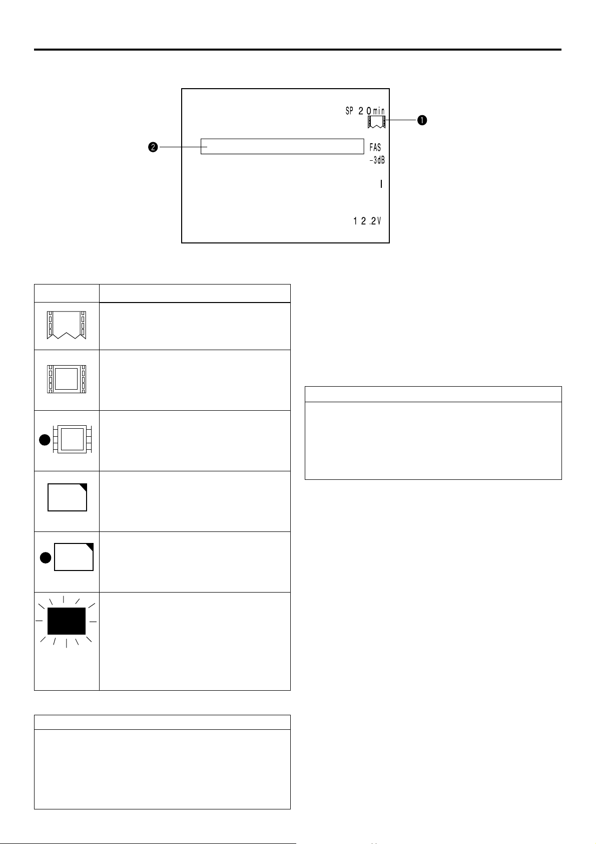
Introduction LCD screen/viewfinder screen
Information from Network Pack KA-DV5000 is displayed on the GY-DV5000 LCD screen/viewfinder screen.
CF FULL!
qCard status displays
Display
No card is inserted in Network Pack.
Flashing display during initialization (after
power on).
LAN card is inserted in Network Pack.
e
(White display)
Video/audio data is being sent from LAN
e
(Red display)
C
F
(White display)
C
card.
CF memory card is inserted in Network Pack.
CF memory card is being recorded with data.
F
Description
wCF Memory card warning display
Displays CF memory card status and system errors.
* For details concerning warning displays, see page 46.
When inputting the 44.1kHz sampling audio signal
This unit is not compatible with audio sampling frequency of
44.1kHz. When playing back a tape recorded with audio of
44.1kHz on GY-DV5000 or when inputting audio in the
44.1kHz mode into the DV terminal, the audio will be processed as muted sound. However,the video will be processed
as normal.
(Red display)
Card is inserted in Network Pack but trans-
X
Flashing display
No colors will be shown on the viewfinder.
Receiving Level Indicator of Wireless LAN
If you are using wireless LAN card that can detect receiving
level, receiving level indicator is shown next to the card status
information on LCD of your camcorder. The indicator shows
value from 5 to 0, 5 means maximum level and 0 means minimum level. (The indicator is for reference. The value does not
guarantee communication.)
mission is not available.
There is possibility of unit malfunction.
Contact your nearest JVC dealer.
4
Page 5
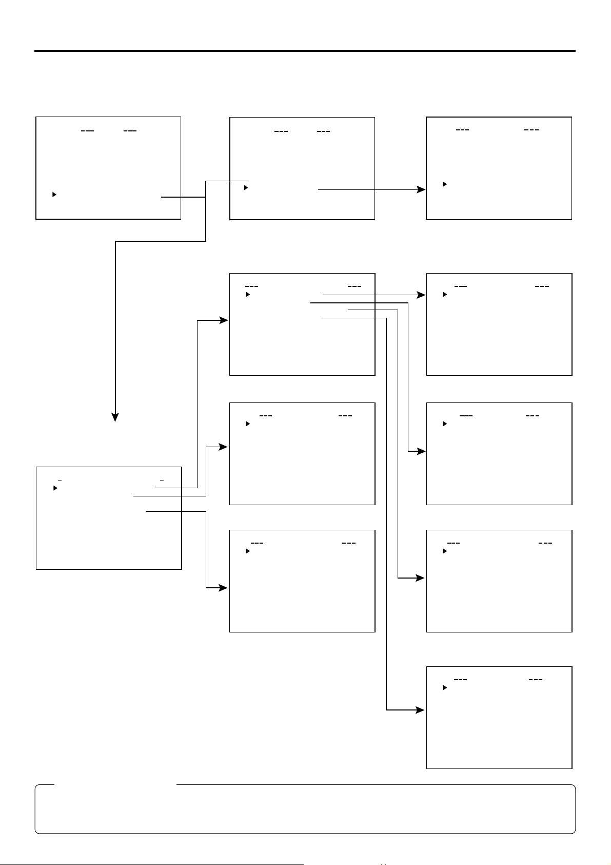
Menu screen Menu screen structure
When attaching Network Pack KA-DV5000 to DV Camcorder GY-DV5000, NETWORK PACK CONFIG menu and MOVIE CLIP menu
are added to the GY-DV5000 TOP MENU screen.
MOVIE CLIP list screen
TOP MENU screen
CAMERA O P ER A T I O
CAMERA P ROC ESS ..
AUD I O / V I DE O ..
LCD / VF . .
TC / UB / CLOCK . .
OTHERS . .
FILE MAN E. .AG
MENU A LL R E S E T C ELANC
NETWORKPACKCONFIG
EXIT
MENU
N
..
TOP MENU screen
AUD I O / V I DEO ..
LCD / VF . .
TC / UB / CLOCK . .
OTHERS . .
FILE MAN E. .AG
MENU A LL R E S E T C ELANC
NETWORKPACKCONFIG
MOVIE CL IP. .
..
EXIT
MENU
..
* Example display when there are clip
files in the CF memory card
(☞ page 23)
mc
00 5.0asf WR/
02 03/02/
00 6.0asf WR/
mc
02 03/02/
00 7.0asf WR/
mc
02 03/02/
00 8.0asf WR/
mc
02 03/02/
PAGE BACK
IEOVMCIP
L
09 0 0:00:
09 3 0:25:
10 1 0:55:
11 0 0:00:
NETWORK PACK CONFIG
menu screen
ORTWENKACK
PONCIGF
NE T WOR K IMA N
ENCODE
MPE G R EC
MOV I ECLI
MENU R E S E T
PAGE BACK
M
Pundr8)e
(
W
TSE P . .U
P
TSE P . .U
TSE PU
RGI
T
ACNLE
C
F
View
(
C
NETWORK MAIN SETUP menu screen
MA I
WOETNRK ET
NETWORK SETUP . .
PORT SETUP . .
WI RELESS LAN SETUP . .
SERVER SETUP . .
PAGE BACK
UP
N
S
NETWORK SETUP menu screen
..
..
UP
S
FOF
HOS T NAME . .
DHCP
IP ADDRESS
SUB
PAGE BACK
NEXT PAGE
WOETNRKET
NET M SAK
..GAT
EWAY
PORT SETUP menu screenENCODE SETUP menu screen
FRAME S I ZE 320x24
BI T RATE 384kb/
MAX FRAME RA T E M I D
STREAM TYPE for WMP
PAGE BACK
ODNCEEET
MOVIE CLIP SETUP menu screen
e
)
r
DELETE ALL CANCE
FORMAT CANCE
PLAY MODE REPEA
PAGE BACK
IEOVMCLIPET
UP
S
0
s
H T T P for WE B Browser
H T T P for Media player
RTSP for
RTSP for
PAGE BACK
WIRELESS LAN SETUP menu screen
UP
S
L
L
T
AD HOC MODE OFF
Primary E SS I D . .
Secondary E SS I D . .
Count r y USA
CH 1 0 CH
WE P K E Y . .
LEAP OFF
PAGE BACK
S
TORPET
UP
..
..
Streamproducer
QuickTime . .
ELIRWESSLAET
..
UP
SS
SERVER SETUP menu screen
S
SETUP ON WEB OFF
LEAP USER NAME . .
LEAP PASSWORD . .
HTTP USER NAME . .
HTTP PASSWORD . .
FTP USER NAME. .
FT P PASSWORD . .
PAGE BACK
VEERSRET
UP
FILE MANAGE settings
When using a CF card, “EXT1” and “EXT2” are additionally displayed in the GY-DV5000 FILE MANAGE screen of LOAD and
STORE FILE column. Saving and reading-out can be performed to and from the CF card with MENU setting value as EXT1 or
EXT2. When deleting files saved on a CF card, delete “EXT1.dat” or “EXT2.dat” file in the data folder of the CF card using a PC.
5
Page 6
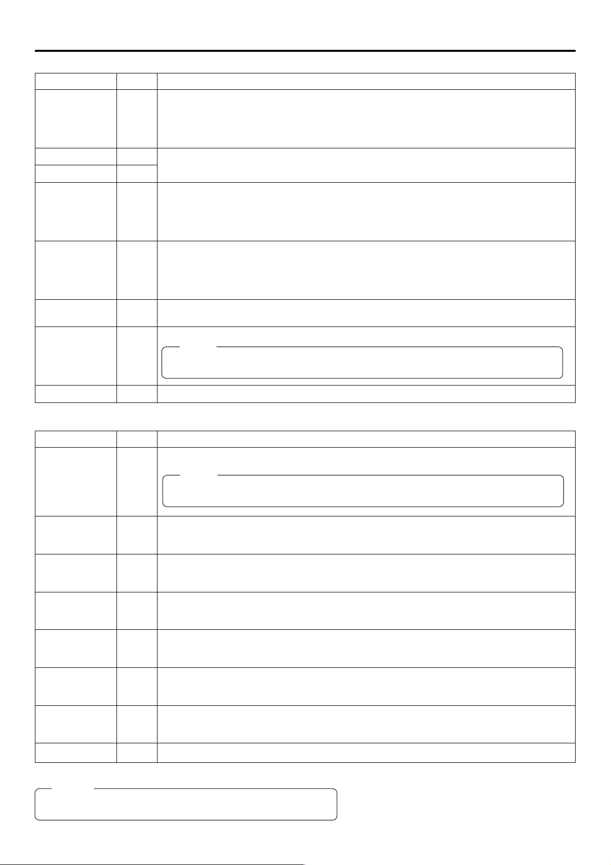
Menu screen NETWORK PACK CONFIG menu screen items
䢇 indicates default factory setting.
Item
NETWORK MAIN SETUP
ENCODE SETUP
FRAME SIZE
VIDEO RATE
MAX FRAME
RATE
Setting
䢇320 × 240
160 × 120
56K
128K
256K
䢇384K
512K
MAX
䢇MID
MIN
BIT RATE
(bps)
512K
384K
256K
Description
Displays menu screen for network related settings. (☞ page 11)
Displays menu screen for setting video and audio compressions.
Sets the video compression size.
320 × 240: Sets the image size to 320 × 240 pixels. (CIF)
160 × 120: Sets the image size to 160 × 120 pixels. (QCIF)
(1/4 image size of CIF.)
Sets streaming speed (bps).
56K: MPEG4 24 kbps G726 16 kbps
128K: MPEG4 104 kbps G726 16 kbps
256K: MPEG4 232 kbps G726 24 kbps
384K: MPEG4 352 kbps G726 32 kbps
512K: MPEG4 472 kbps G726 40 kbps
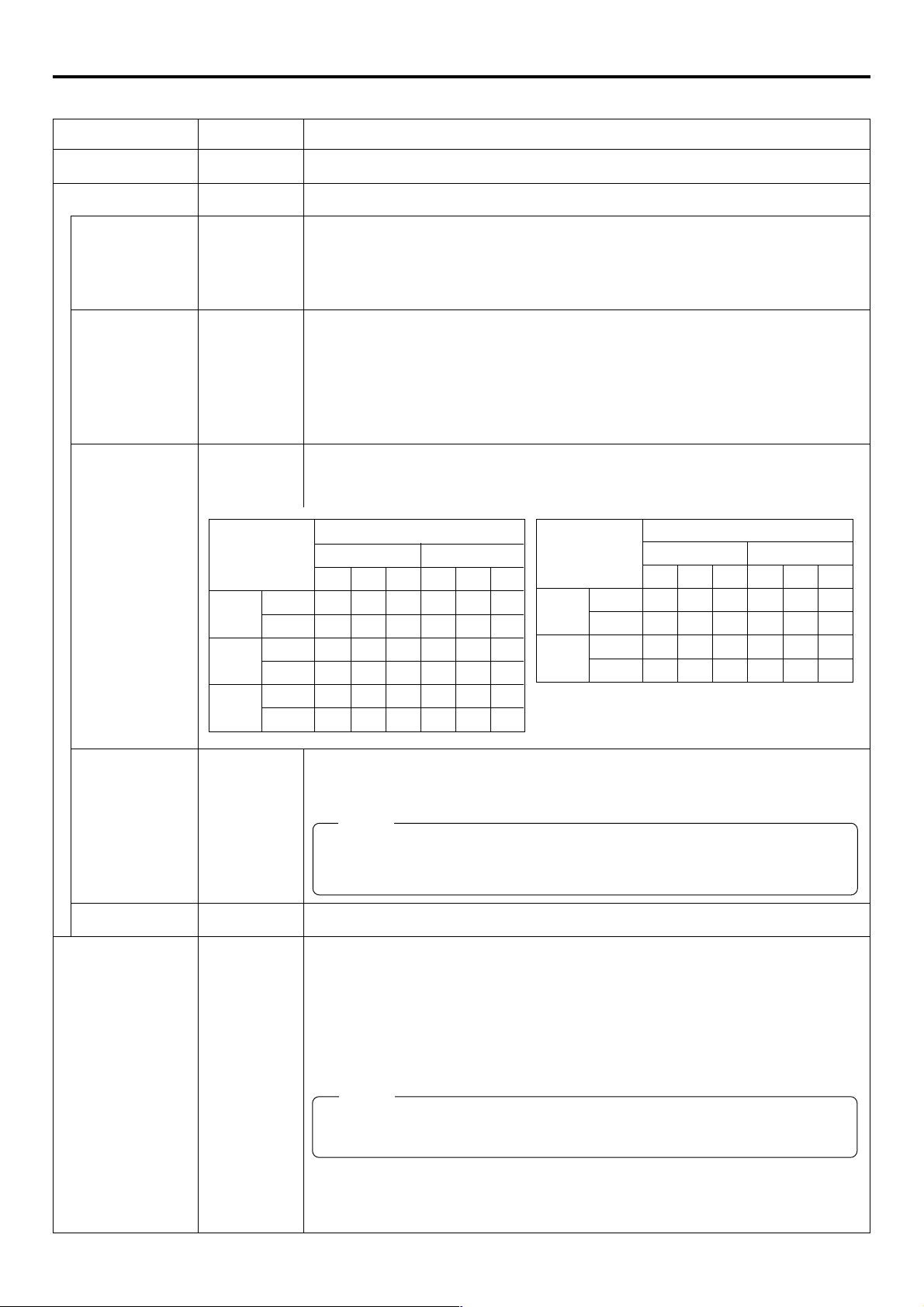
Sets the frame rate per second. Settings are as shown below.
FRAME SIZE
320 × 240 160 × 120
MAX MID MIN MAX MID MIN
NTSC 15 10 7.5 30 15 10
PAL 12.5 5 5 25 12.5 12.5
NTSC 15 10 7.5 30 15 10
PAL 12.5 5 5 25 12.5 5
NTSC 15 7.5 5 30 15 7.5
PAL 12.5 5 5 25 12.5 5
BIT RATE
(bps)
128K
56K
* The frame rates shown in the table are not
guaranteed values.
NTSC 7.5 5 3 15 10 7.5
PAL 5 5 1 12.5 12.5 5
NTSC 3 1 1 10 7.5 5
PAL 1 1 1 12.5 5 5
FRAME SIZE
320 × 240 160 × 120
MAX MID MIN MAX MID MIN
STREAM TYPE
PAGE BACK
MPEG REC
䢇for WMP
for QT
䢇TRIG
SPLIT
OFF
Sets the player for stream playback.
for WMP : Media Player, Streamproducer
for QT : Quick Time
Memo
• No sound will be heard when playing back using QuickTime while in the WMP mode.
• No sound will be heard when playing back using Media Player while in the QT mode.
• Set to WMP mode when recording to CF memory card.
Pressing the SHUTTER dial returns to the NETWORK PACK CONFIG menu screen.
Selects the operation method for recording video data to a CF memory card or sending data
to a remote media from a LAN card.
TRIG: Pressing the VTR trigger button of GY-DV5000 starts operation. Use this setting
when simultaneously recording to a DV tape.
SPLIT: Use this setting when recording or transferring with CF memory card or LAN card
only. Operation starts when pressing the VTR trigger button on the side of GYDV5000.
Memo
When SPLIT is selected, the unit will not operate even when pressing the VTR trigger
button on the front or on the lens.
OFF: Recording will not be made to the CF memory card and streaming data from the
LAN card will not be recorded/sent to the PC even when pressing the VTR trigger
button of GY-DV5000.
→
OVER
6
Page 7

Menu screen NETWORK PACK CONFIG menu screen items
Item
MOVIE CLIP SETUP
DELETE ALL
FORMAT
PLAY MODE
PAGE BACK
MENU RESET
PAGE BACK
Setting
䢇CANCEL
EXECUTE
䢇CANCEL
EXECUTE
OFF
REPEAT 1
䢇REPEAT
䢇CANCEL
EXECUTE
Description
Displays the menu screen for CF memory card related settings such as formatting or deleting all recorded clip files.
Selecting EXECUTE and pressing the SHUTTER dial deletes all clip files on the CF memory
card.
Protected clip files are not deleted.
Selecting EXECUTE and pressing the SHUTTER dial starts formatting the card.
All recorded clips are erased.
Playback is performed from the specified clip file to the latest clip file and pauses at the
specified clip file.
Specified clip file is played backed 3 times.
Playback is performed 3 times from the specified clip file to the latest clip file.
Pressing the SHUTTER dial returns to the NETWORK PACK CONFIG menu screen.
Selecting EXECUTE and pressing the SHUTTER dial returns NETWORK PACK CONFIG
menu screen settings to the original factory settings.
Pressing the SHUTTER dial returns to the TOP MENU screen.
7
Page 8
Menu screen Setting the NETWORK PACK CONFIG menu screen
Menu screen settings can be made regardless of whether a card is inserted. Settings will be stored in the KA-DV5000 memory even
when turning the power off.
STATUS
SHUTTER
MENU
SHUTTER
dial
STATUS
button
POWER switch
1
3200K
2
5600K
.3
5600K
.4
5600K
SHUTTER
AUTO IRIS
FILTER
MENU
1
1
BACK L
NORMAL
SPOT L
ON OFF
8
/
/
64
POWER
EDITSEARCH
ND
ND
STATUS
FULL AUTO BLACK LOLUX
MONITOR
MODE
STRETCH
VTR
NORMAL
COMPRESS
CAM
VTR
MODE switch
CH-1 CH-2
OPEN
POWER
SUPPLY
LCD BRIGHT DISPLAY
AUDIO
LEVEL
CH-1
CH-1 CH-2
ON OFF
PULL
OPEN
FRONT
REAR
CH-2
AUDIO INPUT
AUDIO SELECT
AUTO
MANUAL
NETWORK
PACK
KA-DV5000
POWER SUPPLY
switch
MODE
VTR
CAM
● The NETWORK PACK CONFIG menu
screen will not appear during card initial-
ization (flashing
CAMERA O P ER A T I O
CAMERA P ROC E SS ..
AUD I O / V I D EO ..
LCD / VF . .
TC / UB / CLOCK . .
OTHERS . .
FILE MAN E. .AG
MENU A LL R E S E T C E LAN C
NETWORKPACKCONFIG
EXIT
Cursor
NETWORK PACK CONFIG
NE T WOR K
ENCODE
MPE G R EC
MOV I ECLI
MENU R ES E T
PAGE BACK
M
(
W
TOP MENU screen
Pundr8)e
display).
MENU
N
..
menu screen
ORTWENKACK
PONCIGF
IMA N
TSE PU
TSE P . .U
P
TSE P . .U
RGI
T
C
ACNLE
F
View
(
C
..
e
)
r
\ Settings are made by viewing the LCD screen or viewfinder screen.
If OUTPUT CHAR of the OTHERS (1/2) menu screen is set to ON, the menu
screen also appears on the monitor screen connected to the MONITOR OUT or
Y/C OUT connector.
1.
Set the POWER switch of the GY-DV5000 and KA-DV5000 to ON.
2.
Set the MODE switch.
● Set to “CAM” when shooting a video. (Light the CAM indicator.)
● Set to "VTR" for VTR playback, clip file playback or DV signal recording. (Light
the VTR indicator.)
3.
Press the STATUS button for about 1 seconds. The TOP MENU screen appears.
4.
Turn the SHUTTER dial, move the cursor (t) to NETWORK PACK CONFIG and
press the SHUTTER dial.
● The NETWORK PACK CONFIG menu screen appears.
5.
Select the item to set.
Turn the SHUTTER dial, move the cursor to the desired item to set and press the
SHUTTER dial.
● The selected menu screen appears.
● When selecting MPEG REC or MENU RESET, the setting area flashes and the
setting can be changed. Set the item according to step 7.
● When selecting NETWORK MAIN SETUP, the network related setting screen
appears. (☞ page 10)
NETWORK MAIN SETUP menu screen
(☞ page 10)
FRAME S I ZE 320x24
BI T RATE 384kb/
MAX FRAME RA T E M I D
STREAM TYPE for WMP
PAGE BACK
ODNCEEET
UP
S
Setting
0
s
Setting
6.
Select an item within the menu screen.
Turn the SHUTTER dial, move the cursor (t) to the desired item to set and press
the SHUTTER dial.
● The setting area flashes and the setting can be changed.
7.
Change the setting.
Turn the SHUTTER dial to change the setting and press the SHUTTER dial.
● Flashing of the setting area stops and the new setting is confirmed.
\ When changing multiple settings, repeat steps 6 and 7 above.
8.
Return to the TOP MENU screen.
Turn the SHUTTER dial, move the cursor (t) to PAGE BACK and press the SHUTTER dial.
9.
When quitting menu screen setting and returning to the normal screen, perform
one of the following operations.
● Press the STATUS button.
● Move the cursor (t) to EXIT in the TOP MENU screen and press the SHUTTER
dial.
8
Page 9
Menu screen
Returning the NETWORK PACK CONFIG menu screen to factory settings
STATUS
SHUTTER
MENU
SHUTTER
dial
STATUS
button
FILTER
1
3200K
2
5600K
.3
5600K
.4
5600K
SHUTTER
MENU
AUTO IRIS
1
1
BACK L
NORMAL
SPOT L
ON OFF
8
ND
/
/
ND
64
STATUS
POWER
EDITSEARCH
FULL AUTO BLACK LOLUX
STRETCH
NORMAL
COMPRESS
VTR
MONITOR
MODE
VTR
CAM
CH-1 CH-2
OPEN
POWER
SUPPLY
LCD BRIGHT DISPLAY
AUDIO
LEVEL
CH-1
CH-1 CH-2
ON OFF
PULL
OPEN
FRONT
REAR
CH-2
AUDIO INPUT
AUDIO SELECT
AUTO
MANUAL
NETWORK
PACK
KA-DV5000
NETWORK PACK CONFIG
menu screen
ORTWENKACK
NE T WOR K
ENCODE
MPE G R EC
MOV I ECLI
MENU R ES E T
PAGE BACK
M
Pundr8)e
(
W
PONCIGF
IMA N
TSE P . .U
P
TSE P . .U
(
MENU R E S E T
TSE PU
RGI
T
XCETEU
E
F
Vi
C
..
ew
1.
Press the STATUS button for about 1 seconds to display the TOP MENU screen.
2.
Check to see that the card status display has changed from a flashing to constant
display.
3.
Turn the SHUTTER dial to select NETWORK PACK CONFIG and press the SHUT-
e
)
r
TER dial.
● The NETWORK PACK CONFIG menu screen appears.
4.
Turn the SHUTTER dial to set MENU RESET to “EXECUTE” and press the SHUT-
TER dial.
● When resetting the menu, “MENU RESET..” will appear at the bottom of the
screen for about 5 seconds.
● The NETWORK PACK CONFIG menu screen settings will return to the factory
settings.
9
Page 10
Network settings Setting the NETWORK MAIN SETUP menu screen
When using a LAN card, network related settings for KA-DV5000 are made using NETWORK MAIN SETUP of the NETWORK PACK
CONFIG menu. Settings will be stored in the KA-DV5000 memory even when turning the power off.
STATUS
SHUTTER
MENU
SHUTTER
dial
STATUS
button
POWER switch
1
3200K
2
5600K
.3
5600K
.4
5600K
SHUTTER
AUTO IRIS
FILTER
MENU
BACK L
NORMAL
SPOT L
ON OFF
EDITSEARCH
1
8
ND
/
1
ND
64
/
STATUS
FULL AUTO BLACK LOLUX
POWER
MONITOR
MODE
STRETCH
VTR
NORMAL
COMPRESS
CAM
VTR
CH-1 CH-2
OPEN
POWER
SUPPLY
LCD BRIGHT DISPLAY
AUDIO
LEVEL
CH-1
CH-1 CH-2
ON OFF
PULL
OPEN
FRONT
REAR
CH-2
AUDIO INPUT
AUDIO SELECT
AUTO
MANUAL
NETWORK
PACK
KA-DV5000
POWER SUPPLY
switch
TOP MENU screen
CAMERA O P ER A T I O
CAMERA P ROC ESS ..
AUD I O / V I DE O ..
LCD / VF . .
TC / UB / CLOCK . .
OTHERS . .
FILE MAN E. .AG
MENU A LL R E S E T C E LAN C
NETWORKPACKCONFIG
EXIT
MENU
N
..
..
NETWORK PACK CONFIG
menu screen
ORTWENKACK
NE T WOR K
ENCODE
MPE G R EC
MOV I ECLI
MENU R ES E T
PAGE BACK
M
Pundr8)e
(
W
PONCIGF
IMA N
TSE PU
TSE P . .U
P
TSE P . .U
(
C
F
RGI
T
ACNLE
C
Vi..ew
e
)
r
NETWORK MAIN SETUP menu screen
MA I
WOETNRK ET
NETWORK SETUP . .
PORT SETUP . .
WI RELESS LAN SETUP . .
SERVER SETUP . .
PAGE BACK
UP
N
S
\ Settings are made by viewing the LCD screen or viewfinder screen.
If OUTPUT CHAR of the OTHERS (1/2) menu screen is set to ON, the menu screen
also appears on the monitor screen connected to the MONITOR OUT or Y/C OUT
connector.
Display the NETWORK SETUP menu screen
1.
Turn on the GY-DV5000 and KA-DV5000 power.
2.
Check to see that the card status display has changed from a flashing to constant
display.
3.
Press the STATUS button for about 1 seconds to display the TOP MENU screen.
4.
Turn the SHUTTER dial, move the cursor (t) to NETWORK PACK CONFIG and
press the SHUTTER dial.
● The NETWORK PACK CONFIG menu screen appears.
5.
Turn the SHUTTER dial, move the cursor (t) to NETWORK MAIN SETUP and
press the SHUTTER dial.
● The NETWORK MAIN SETUP menu screen will appear.
The NETWORK MAIN SETUP menu screen is structured by four screens.
NETWORK SETUP
PORT SETUP
WIRELESS LAN SETUP
SERVER SETUP
NETWORK SETUP menu screen
..
..
UP
S
–––
HOS T NAME . .
DHCP
IP ADDRESS
SUB
PAGE BACK
NEXT PAGE
WOETNRKET
NET M SAK
..GAT
EWAY
6.
Turn the SHUTTER dial, move the cursor (t) to SETUP and press the SHUTTER
dial.
● The selected SETUP screen appears.
Items with “..” at the end of the name are set in the INPUT screen.
7.
To return to the NETWORK MAIN SETUP menu screen, select PAGE BACK and
press the SHUTTER dial.
8.
To return to the normal screen after completing setting, perform one of the follow-
ing operations.
● Press the STATUS button
● Select PAGE BACK to return to the TOP MENU screen. Select EXIT in the TOP
MENU screen and press the SHUTTER dial.
10
Page 11

Network settings NETWORK MAIN SETUP menu screen items
NETWORK SETUP menu screen indicates default factory setting.
Item
Setting
Description
HOST NAME
DHCP
IP ADDRESS
SUBNET MASK
GATE WAY
PAGE BACK
PORT SETUP menu screen
Item
OFF
ON
Setting
Displays the host name input setting screen. (4 ~ 64 alphanumerical characters)
[Factory setting: none]
Select whether DHCP server is used.
OFF: Use this setting when using LAN connection rather than DHCP.
When this setting is used, IP ADDRESS and SUBNET MASK, GATEWAY must also be set.
ON: Use this setting when using DHCP connection.
When using this setting, IP ADDRESS and
* When DHCP is set to ON, WLAN ADHOC MODE cannot be set to AHDM or IBSS.
Displays the IP address setting screen.
When using LAN connection with DHCP set to OFF, this setting is required. Set a unique IP address.
IP ADDRESS setting is not available when DHCP is set to ON.
[Factory setting] 192.168.100.101]
Displays the subnet mask input screen.
This setting is required when using LAN connection with DHCP set to OFF.
SUBNET MASK
[Factory setting: 255.255.255.000]
Displays the gateway address input screen.
GATEWAY setting is not available when DHCP is set to ON.
[Factory setting: 192.168.100.254]
Pressing the SHUTTER dial returns to the NETWORK MAIN SETUP menu screen.
setting is not available if DHCP is set to ON.
SUBNET MASK
Description
, GATEWAY are automatically set.
HTTP for WEB
Browser
HTTP for
Media player
RTSP for
Streamproducer
RTSP for Quick
Time
PAGE BACK
1
:
80
:
32767
1
:
8080
:
32767
1
:
8554
:
32767
1
:
554
:
32767
The screen for setting RTSP and HTTP port numbers appears.
HTTP for Web Browser can be set with the Web browser HTTP port number and HTTP for Media
Player can be set with the Media Player HTTP port number. RTSP for Streamproducer can be set
with the Streamproducer RTSP port number and RTSP for Quick Time can be set with the Quick
Time RTSP port number.
Normally, the unit can be used without changing the factory settings.
If there are port restrictions for the LAN environment of your PC, consult your network administrator.
* When changing a port number, refer to “5-1. Connecting with Camcorder” of the “Streamproducer”
User’s Guide of the network distribution software to change settings.
* Do not use the same port numbers for RTSP and HTTP.
* When a port number is changed, switch the power of the GY-DV5000 off once, and then switch it
on again.
Pressing the SHUTTER dial returns to the NETWORK SETUP menu screen.
→
OVER
11
Page 12
Network settings NETWORK MAIN SETUP menu screen items
WIRELESS LAN SETUP menu screen indicates default factory setting.
Item
AD HOC MODE
Primary ESS ID
Secondary ESS ID
Country
CH
WEP KEY
LEAP
Setting
OFF
AHDM
IBSS
NONE
NONE
USA
EU
FRN
SPN
JPN
1CH
:
10CH
:
14CH
ON
OFF
Description
Wireless LAN setting
OFF: Use this setting when performing communication via access point.
AHDM/IBSS: Use this setting when performing communication in AD HOC mode with a PC con-
nected with a wireless LAN card. (☞ page 16)
* When this item is set to AHDM or IBSS, DHCP cannot be set to ON.
Displays the wireless LAN ESS-ID input setting screen (Max. 32 alphanumerical characters)
Setting for the country using wireless LAN
USA: USA, EU: Europe, FRN: France
SPN: Spain, JPN: Japan
(Set according to operating environment.)
Wireless LAN channel setting
CH setting changes depending on the Country setting.
USA: 1 ~ 11CH, EU: 1 ~ 13CH, FRN: 10 ~ 13CH, SPN: 10, 11CH, JPN: 1 ~ 14CH
When encrypting data, set the WEP KEY (10 or 26 characters consisting or letters a ~ f and numbers). Must be compatible with access point authentication for the use of this item.
Set to ON when connecting a Cisco Systems wireless LAN device and using the LEAP function.
Memo
The LEAP function is exclusive to Cisco Systems wireless LAN devices. For details concerning
the LEAP function, see the instruction manual accompanying the wireless LAN device.
PAGE BACK
SERVER SETUP menu screen
Item
SETUP ON WEB
LEAP USER
NAME
LEAP
PASSWORD
HTTP USER
NAME
HTTP
PASSWORD
FTP USER NAME
FTP PASSWORD
PAGE BACK
Setting
ON
OFF
Pressing the SHUTTER dial returns to the NETWORK MAIN SETUP menu screen.
Description
Set to ON when changing the USER NAME and PASSWORD from the Web.
Memo
If higher security is desired, set this function to OFF so that changes cannot be made from the
Web.
Displays the LEAP USER NAME input screen. (4 ~ 32 alphanumerical characters)
Set when using the LEAP function.
[Default setting: leap-user]
Displays the LEAP PASSWORD input screen. (4 ~ 32 alphanumerical characters)
Set when using the LEAP function.
[Default setting: ka-dv-jvc]
Displays the HTTP USER NAME input screen. (3 ~ 8 alphanumerical characters)
Set when connecting from the Web browser.
[Default setting: jvc]
Displays the HTTP PASSWORD input screen. (4 ~ 8 alphanumerical characters)
Set when connecting from the Web browser.
[Default setting: ka-dv5k]
Displays the FTP USER NAME input screen. (3 ~ 8 alphanumerical characters)
Used when uploading USER PAGE.
[Default setting: ftp-user]
Displays the FTP PASSWORD input screen. (4 ~ 8 alphanumerical characters)
Used when uploading USER PAGE.
[Default setting: ka-dv]
Pressing the SHUTTER dial returns to the NETWORK MAIN SETUP menu screen.
Memo
For details concerning user name and password settings, see page 13.
12
Page 13

Network settings Setting user names and passwords
\Changing the user name
When changing the HTTP USER NAME or FTP USER NAME, “NEXT STEP SET PASSWORD” will appear on the screen and the
PASSWORD menu screen is displayed.
When input is canceled in the PASSWORD menu screen, the user name will also be canceled.
It is possible to change only the password.
When changing the LEAP USER NAME setting, the PASSWORD menu screen will not appear automatically.
\Setting passwords
Set LEAP, HTTP and FTP PASSWORD using the procedure shown below.
1.
First, enter the currently used password when “ENTER OLD PASSWORD” is displayed.
2.
Next, enter the new password when “ENTER NEW PASSWORD” is displayed.
3.
Lastly, enter the new password again when “CONFIRM NEW PASSWORD” is displayed.
Caution
• Do not forget to take a memo of the password. The password cannot be redisplayed.
• Each character input on the PASSWORD menu screen is hidden using asterisks (*).
• When performing MENU RESET, the unit will return the default factory settings.
13
Page 14
Network settings Making network related settings
Network related settings are made in the individual input setting screens.
Here, HTTP USER NAME is set as an example. Other settings are also made in the same manner.
STOP button
STATUS
SHUTTER
MENU
SHUTTER
dial
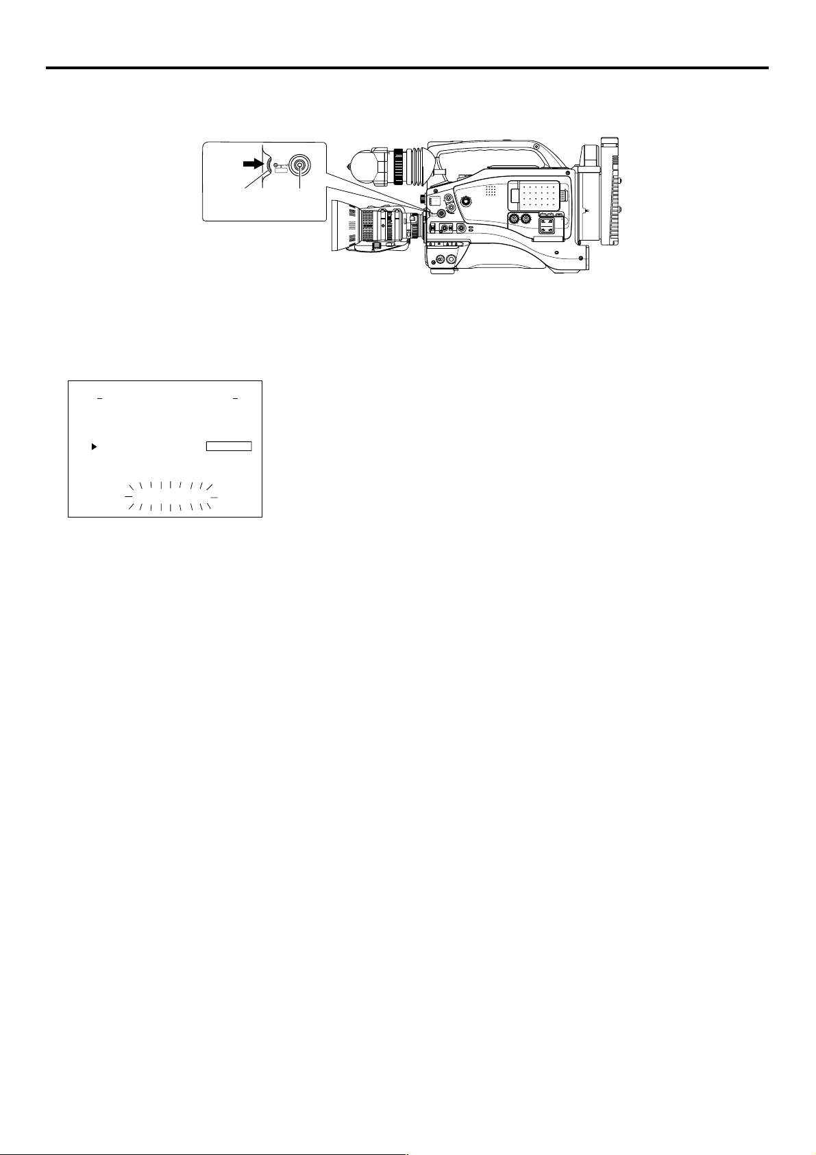
HTTP USER NAME input setting screen
Currently inputted number of characters/
max.number of characters
RSEU
NAMETTPH
jvc
Setting area
abc d e fghijklmnopqrst uv
wx y z 0 12345 67 8 9
Character
_
¯
.
selection area
BS:
Backspace (
delete previous character
)
: The set text is confirmed and
returns to the previous screen.
6: The set text is canceled and
returns to the previous screen.
RSEU
NAMETTPH
_
jvc
abc d e fghi j klmnopqrst u v
wx y z 0 12345 67 8 9
_
jvc 1
_
BSA
¯
.
RSEU
NAMETTPH
BSA
4/8
5
6
3/8
6
8
/
STATUS
button
EDITSEARCH
MONITOR
FILTER
1
3200K
1
2
8
5600K
ND
/
.3
5600K
1
.4
5600K
/
ND
64
STATUS
SHUTTER
MENU
AUTO IRIS
BACK L
NORMAL
SPOT L
ON OFF
POWER
FULL AUTO BLACK LOLUX
STRETCH
NORMAL
COMPRESS
VTR
MODE
VTR
CAM
CH-1 CH-2
Example: Changing HTTP USER NAME from jvc to jvc-1234
\ Select HTTP USER NAME in the SERVER SETUP menu screen and press the
SHUTTER dial.
● The USER NAME input setting screen appears.
1.
Characters are selected from the character selection area on the bottom of the
screen.
Turn the SHUTTER dial to flash “_” in the character selection area and press the
SHUTTER dial.
● The setting changes to “jvc_” and the following digit of the setting area flashes.
2.
Turn the SHUTTER dial to select “1” in the character selection area and press the
SHUTTER. dial.
● The setting changes to “jvc_1” and the following digit of the setting area flashes.
3.
Repeat the above step to set “jvc_1234” in the setting area.
\ To delete or edit set characters, select “BS” within the character selection area and
press the SHUTTER dial.
The previous character will be deleted. The character on the left will be deleted each
time this operation is repeated.
\ When turning the SHUTTER dial while holding down the STOP button, the cursor will
move 5 characters at a time.
\ The currently inputted number of characters and the maximum number of characters
are displayed on the upper right of the screen.
\ To cancel a setting, select the “6” within the character selection area and press the
SHUTTER dial. The unit will return to the previous screen (SERVER SETUP menu
screen).
OPEN
POWER
SUPPLY
LCD BRIGHT DISPLAY
AUDIO
LEVEL
CH-1
CH-1 CH-2
ON OFF
PULL
OPEN
FRONT
REAR
CH-2
AUDIO INPUT
AUDIO SELECT
AUTO
MANUAL
NETWORK
PACK
KA-DV5000
abc d e fghi j klmnopqrst u v
wx y z 0 12345 67 8 9
_
jvc 1234
abc d e fghi j klmnopqrst u v
wx y z 0 12345 67 8 9
_
¯
6
.
BSA
RSEU
NAMETTPH
8
/
_
¯
6
BSA
.
4.
When completed, select “ ” within the character selection area and press the
SHUTTER dial.
● When changing the HTTP USER NAME or FTP USER NAME, “NEXT STEP
SET PASSWORD” will appear on the screen and the PASSWORD menu screen
is displayed . Set the password using the procedure shown above.
8
Memo
When setting is completed for items other than HTTP USER NAME and FTP USER
NAME, the unit will return to the previous screen (NETWORK MAIN SETUP or
SERVER SETUP menu screen).
14
Page 15
Network settings Detailed IP settings (LAN)
MONITOR
EDITSEARCH
FILTER
STATUS
SHUTTER
MENU
AUTO IRIS
BACK L
NORMAL
SPOT L
STRETCH
NORMAL
COMPRESS
FULL AUTO
BLACK
LOLUX
MODE
POWER
OFF
VTR
OPEN
VTR
CAM
3200K
5600K
5600K
5600K
ND
.3
.4
64
CH-1
UDIO INPUT
UDIO SELECT
CH-2
CH-1
CH-2
ONT
REAR
MANUALAL
AUDIO
LEVEL
CH-1
CH-2
PULL
OPEN
LCD
BRIGHT
DISPLAY
NETW
ORK
CK
KA-D
V5000
WER
SUPPL
OFF
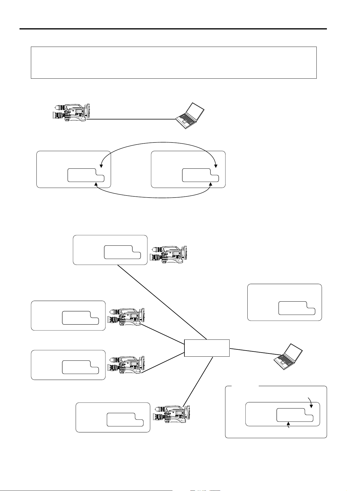
Example of IP address and subnet mast settings when using LAN is shown below.
●Operation is only guaranteed for Windows 2000, Windows XP Home Edition or Windows XP Professional.
●Internet Explorer 5.0 or later
●Windows Media Player 7.01 or later (WM9 is not supported.)
1. For 1:1 communication between PC and GY-DV5000/KA-DV5000
OPEN
EDITSEARCH
MONITOR
FILTER
1
3200K
1
2
8
5600K
NDND/
.3
5600K
1
.4
5600K
ND
64
/
STATUS
SHUTTER
MENU
AUTO IRIS
FULL AUTO
BACK L
NORMAL
SPOT L
POWER
ONONOFF
POPOWER
SUPPL
Y
LCD
BRIGHT
DISPLAY
ONONOFF
AUDIO
PULL
LEVEL
OPEN
FRFRONT
REAR
BLACK
LOLUX
CH-1
CH-2
CH-1
CH-2
AUDIO INPUT
MODE
STRETCH
AUDIO SELECT
VTR
NORMAL
CH-1
CH-2
COMPRESS
AUTUTO
CAM
MANU
NETW
ORK
PACK
KA-D
V5000
VTR
10/100 BASE-T cross cable
* For the PC settings when using a LAN card,
refer to the instruction manual included with
the LAN card.
Set a unique number to avoid doubling
* Up to 3 clients can access at the same time.
DHCP OFF
PROXY SERVER NO USE
DHCP SERVER NO USE
IP ADDRESS 192. 168. 100. 101
NETMASK 255. 255. 255. 000
IP ADDRESS 192. 168. 100. 100
NETMASK 255. 255. 255. 000
Set the same network group
2. For communication between PC and multiple GY-DV5000/KA-DV5000
DHCP OFF
IP ADDRESS 192. 168. 100. 101
NETMASK 255. 255. 255. 000
DHCP OFF
IP ADDRESS 192. 168. 100. 102
NETMASK 255. 255. 255. 000
EDITSEARCH
MONITOR
FILTER
1
3200K
1
2
8
5600K
NDND/
.3
5600K
1
.4
/
5600K
ND
64
STATUS
SHUTTER
MENU
AUDIO
LEVEL
AUTO IRIS
FULL AUTO
BLACK
LOLUX
CH-1
CH-2
MODE
BACK L
STRETCH
VTR
NORMAL
NORMAL
SPOT L
COMPRESS
CAM
POWER
VTR
ONONOFF
OPEN
POPOWER
SUPPL
Y
LCD
BRIGHT
DISPLAY
ONONOFF
PULL
OPEN
FRFRONT
REAR
CH-1
CH-2
AUDIO INPUT
AUDIO SELECT
CH-1
CH-2
AUTUTO
MANU
NETW
ORK
PACK
KA-D
V5000
OPEN
EDITSEARCH
MONITOR
FILTER
1
3200K
1
2
8
5600K
NDND/
.3
5600K
1
.4
/
5600K
ND
64
STATUS
SHUTTER
MENU
AUTO IRIS
FULL AUTO
BACK L
NORMAL
SPOT L
POWER
ONONOFF
POPOWER
SUPPL
Y
LCD
BRIGHT
DISPLAY
ONONOFF
AUDIO
PULL
LEVEL
OPEN
FRFRONT
REAR
BLACK
LOLUX
CH-1
CH-2
CH-1
CH-2
AUDIO INPUT
MODE
STRETCH
AUDIO SELECT
VTR
NORMAL
CH-1
CH-2
COMPRESS
AUTUTO
CAM
MANU
NETW
ORK
PACK
KA-D
V5000
VTR
PROXY SERVER NO USE
DHCP SERVER NO USE
IP ADDRESS 192. 168. 100. 100
NETMASK 255. 255. 255. 000
DHCP OFF
IP ADDRESS 192. 168. 100. 103
NETMASK 255. 255. 255. 000
DHCP OFF
IP ADDRESS 192. 168. 100. 104
NETMASK 255. 255. 255. 000
Hub
OPEN
EDITSEARCH
MONITOR
FILTER
1
3200K
1
2
8
5600K
NDND/
.3
5600K
1
.4
/
5600K
ND
64
STATUS
SHUTTER
MENU
AUTO IRIS
FULL AUTO
BACK L
NORMAL
SPOT L
POWER
ONONOFF
POPOWER
SUPPL
Y
LCD
BRIGHT
DISPLAY
ONONOFF
AUDIO
PULL
LEVEL
OPEN
FRFRONT
REAR
BLACK
LOLUX
CH-1
CH-2
CH-1
CH-2
AUDIO INPUT
MODE
STRETCH
AUDIO SELECT
VTR
NORMAL
CH-1
CH-2
COMPRESS
AUTUTO
CAM
MANU
NETW
ORK
PACK
KA-D
VTR
V5000
10/100 BASE-T straight cable
Caution
Set a unique number to avoid doubling
OPEN
EDITSEARCH
MONITOR
FILTER
1
3200K
1
2
8
5600K
NDND/
.3
5600K
1
.4
/
5600K
ND
64
STATUS
SHUTTER
MENU
AUTO IRIS
FULL AUTO
BACK L
NORMAL
SPOT L
POWER
ONONOFF
POPOWER
SUPPL
Y
LCD
BRIGHT
DISPLAY
ONONOFF
AUDIO
PULL
LEVEL
OPEN
FRFRONT
REAR
BLACK
LOLUX
CH-1
CH-2
CH-1
CH-2
AUDIO INPUT
MODE
STRETCH
AUDIO SELECT
VTR
NORMAL
CH-1
CH-2
COMPRESS
AUTUTO
CAM
MANU
NETW
ORK
PACK
KA-D
VTR
V5000
15
IP ADDRESS 192. 168. 100. XXX
NETMASK 255. 255. 255. 000
Set the same network group
Page 16
Network settings Detailed network settings (WLAN)
MONITOR
EDITSEARCH
FILTER
STATUS
SHUTTER
MENU
AUTO IRIS
BACK L
NORMAL
SPOT L
STRETCH
NORMAL
COMPRESS
FULL AUTO
BLACK
LOLUX
MODE
POWER
OFF
VTR
OPEN
VTR
CAM
3200K
5600K
5600K
5600K
ND
.3
.4
64
CH-1
UDIO INPUT
UDIO SELECT
CH-2
CH-1
CH-2
ONT
REAR
MANUALAL
AUDIO
LEVEL
CH-1
CH-2
PULL
OPEN
LCD
BRIGHT
DISPLAY
NETW
ORK
CK
KA-D
V5000
WER
SUPPL
OFF
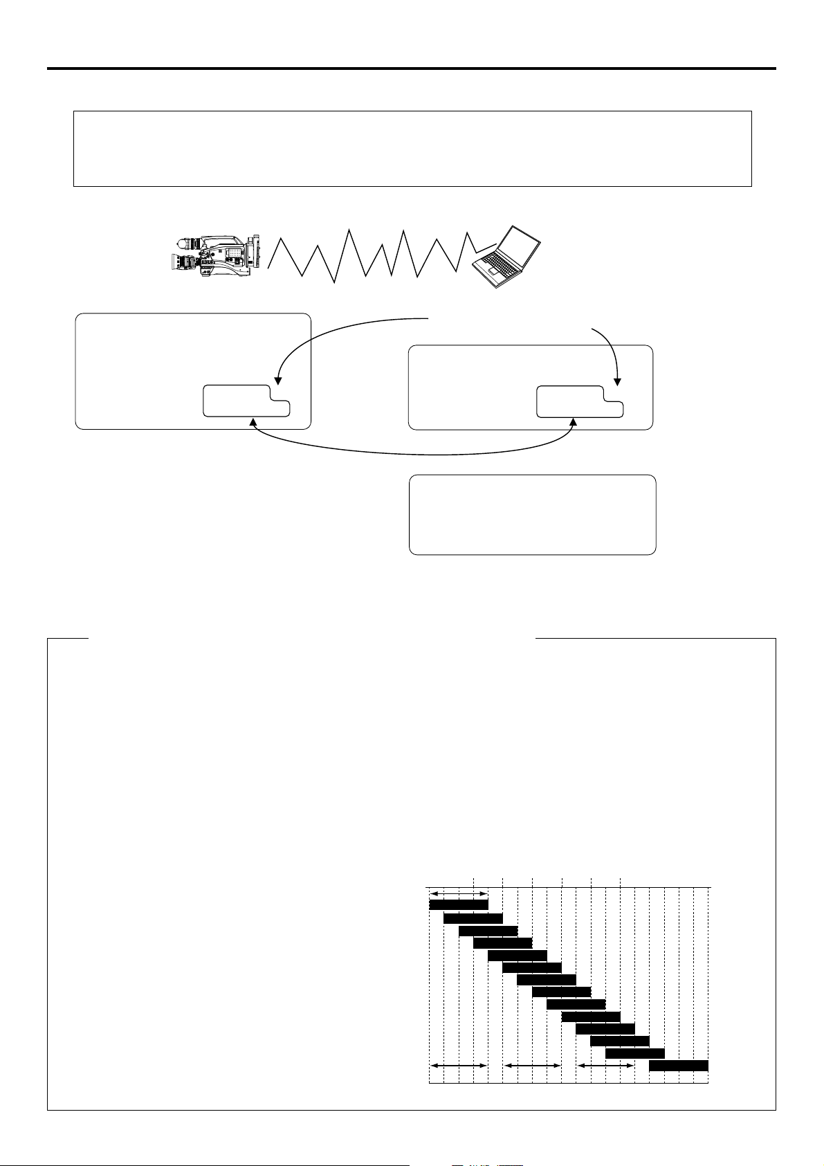
Example of network settings when using wireless LAN is shown below.
●Operation is only guaranteed for Windows 2000, Windows XP Home Edition or Windows XP Professional.
●Internet Explorer 5.0 or later
●Windows Media Player 7.01 or later (WM9 is not supported.)
1. For communication with PC without returning access point (Ad hoc mode)
OPEN
EDITSEARCH
MONITOR
FILTER
1
3200K
1
2
8
5600K
NDND/
.3
5600K
1
.4
/
5600K
ND
64
STATUS
SHUTTER
MENU
AUTO IRIS
FULL AUTO
BACK L
NORMAL
SPOT L
POWER
ONONOFF
POPOWER
SUPPL
Y
LCD
BRIGHT
DISPLAY
ONONOFF
AUDIO
PULL
LEVEL
OPEN
FRFRONT
REAR
BLACK
LOLUX
CH-1
CH-2
CH-1
CH-2
AUDIO INPUT
MODE
STRETCH
AUDIO SELECT
VTR
NORMAL
CH-1
CH-2
COMPRESS
AUTUTO
CAM
MANU
NETW
ORK
PACK
KA-D
VTR
V5000
DHCP OFF
WLAN AD HOC MODE ON
WLAN ESS ID abcdef
WLAN CH 2
IP ADDRESS 192. 168. 100. 101
NETMASK 255. 255. 255. 000
Set a unique number to avoid doubling
PROXY SERVER OFF
DHCP SERVER OFF
IP ADDRESS 192. 168. 100. 100
NETMASK 255. 255. 255. 000
* Do not perform encryption of the
wireless LAN.
Set the same network group
PC wireless LAN driver settings
NetworkType 802. 11 Ad Hoc Mode
ESS ID abcdef
Channel 2
Encryption Mode Open System
* For the PC settings when using a LAN card, refer to
the instruction manual included with the LAN card.
Cautionary items concerning Wireless LAN (WLAN)
● For the WLAN ESS ID, input the values of ESSID set in:
Ad hoc mode: PC of other party
Infrastructure: Access point
● WLAN AD HOC MODE
When IBSS is set, the NETWORK MODE setting of the wireless LAN card on the PC side must be set to 802.11 Adhoc.
When AHDM is set, the NETWORK MODE setting of the wireless LAN card on the PC side must be set to Adhoc. Depending
on the LAN card on the PC side, only 802.11 Adhoc mode may be available.
● WLAN CH is the wireless frequency band used for communication. If there is an access point, adapter, etc., using the
same band in the proximity, there may be a hindrance in the communication and may reduce throughput or the quality of
communication. When setting, check the settings of surrounding access points, etc., to avoid doubling.
Frequency bands (ISM bands) and channels
(IEEE803.11b standard)
N. America : FCC / 2.412~2.462GHz (11 channels)
Europe : CE ETSI / 2.412~2.472GHz (13 channels)
Japan : 2.412~2.4835GHz (14 channels)
France : 2.457~2.472GHz (4 channels)
Spain : 2.457~2.462GHz (2 channels)
Since adjacent channels causes signal interference, channels
are normally spaced 5 channels apart.
(Set according to operating environment.)
Approx.
11MHz
2412
2417
2422
2427
2432
2437
2442
2447
2452
2457
2462
2467
2472 2484
1ch
2ch
3ch
4ch
5ch
6ch
7ch
8ch
9ch
10ch
11ch
12ch
13ch
1ch frequency band1ch frequency band 1ch frequency band11ch frequency band 1ch frequency band14ch frequency band6ch frequency band6ch frequency band
14ch
Center
frequency
16
→
OVER
Page 17

Network settings Detailed network settings (WLAN)
MONITORMONITOR
EDITSEARCHEDITSEARCH
FILTERFILTER
STATUSSTATUS
SHUTTERSHUTTER
MENUMENU
AUTO IRISAUTO IRIS
BACK LBACK L
NORMALNORMAL
SPOT LSPOT L
STRETCHSTRETCH
NORMALNORMAL
COMPRESSCOMPRESS
FULL AUTOFULL AUTO BLACKBLACK LOLUXLOLUX
MODEMODE
POWERPOWER
ONON OFFOFF
VTRVTR
OPENOPEN
VTRVTR
CAMCAM
1
3200K3200K
5600K5600K
5600K5600K
5600K5600K
NDND
/
/
NDND
2
.3.3
.4.4
1
8
1
6464
CH-1CH-1
AUDIO INPUTUDIO INPUT
AUDIO SELECTUDIO SELECT
CH-2CH-2
CH-1CH-1CH-2CH-2
FRFRONTONT
REARREAR
AUTUTO
MANUMANUALAL
AUDIOAUDIO
LEVELLEVEL
CH-1CH-1 CH-2CH-2
PULLPULL
OPENOPEN
LCDLCDBRIGHTBRIGHT DISPLAYDISPLAY
NETWNETWORKORK
PACKCK
KA-DKA-DV5000V5000
POPOWERWER
SUPPLSUPPLY
ONONOFFOFF
DHCP OFF
WLAN AD HOC MODE OFF
WLAN ESS ID abcdef
WLAN CH 2
IP ADDRESS 192. 168. 100. 102
NETMASK 255. 255. 255. 000
DHCP OFF
WLAN AD HOC MODE OFF
WLAN ESS ID abcdef
WLAN CH 2
IP ADDRESS 192. 168. 100. 103
NETMASK 255. 255. 255. 000
DHCP OFF
WLAN AD HOC MODE OFF
WLAN ESS ID abcdef
WLAN CH 2
IP ADDRESS 192. 168. 100. 104
NETMASK 255. 255. 255. 000
IP ADDRESS 192. 168. 100. XXX
NETMASK 255. 255. 255. 000
DHCP OFF
WLAN AD HOC MODE OFF
WLAN ESS ID abcdef
WLAN CH 2
IP ADDRESS 192. 168. 100. 101
NETMASK 255. 255. 255. 000
PC wireless LAN driver settings
NetworkType Infrastructure
ESS ID abcdef
Channel 2
Encryption Mode Open System
PROXY SERVER NO USE
DHCP SERVER NO USE
IP ADDRESS 192. 168. 100. 100
NETMASK 255. 255. 255. 000
STATION
ESS ID abcdef
Channel 2
Encryption Mode Open System
Network Type (Ad Hoc/Infrastructure)
Make sure ESS ID and Channel settings
are the same.
Set a unique number to avoid doubling
Set the same network group
2. For communication with PC via access point (Infrastructure mode)
* For the PC settings when using a LAN card,
refer to the instruction manual included with
the LAN card.
Memo
For network settings and LAN card driver settings, refer to the respective instruction manuals.
17
Page 18
Recording on a CF card Formatting a CF memory card
If the CF memory card is unformatted when performing any of the operations shown below, “NO CF FORMAT” will appear in the LCD
screen/viewfinder screen.
• Executing DELETE ALL
• Recording to the CF memory card
Caution
STATUS
If the unit enters MOVIE CLIP by operating the menu or the VCR trigger button during formatting CF card, a display
of the LCD viewer can go wrong. However, if you operate the menu after formatting has been completed, you will be
able to regain a normal display.
C
RGI
T
ACNLE
C
F
e
)
r
NO CF FORMAT!
NETWORK PACK CONFIG
menu screen
ORTWENKACK
NE T WOR K
ENCODE
MPE G R EC
MOV I ECLI
MENU R E S E T
PAGE BACK
M
Pundr8)e
(
W
PONCIGF
IMA N
TSE PU
TSE P . .U
P
TSE P . .U
(
C
F
View
SHUTTER
dial
1.
Press the STATUS button for about 1 seconds to display the TOP MENU screen.
2.
Use the SHUTTER dial to select NETWORK PACK CONFIG menu screen ¥
MOVIE CLIP SETUP menu screen.
3.
Set FORMAT in the MOVIE CLIP SETUP menu screen to “EXECUTE” and press
the SHUTTER dial.
● The formatting begins. During formatting, “FORMAT” appears on the screen.
4.
When formatting is completed, to the MOVIE CLIP SETUP menu screen returns.
The FORMAT setting will return to CANCEL.
5.
To return to the NETWORK PACK CONFIG menu screen, select PAGE BACK and
press the SHUTTER dial.
● To return to the normal screen, press the STATUS button.
SHUTTER
MENU
STATUS
button
1
2
.3
.4
SHUTTER
AUTO IRIS
FILTER
3200K
5600K
5600K
5600K
MENU
ON OFF
EDITSEARCH
1
8
ND
/
1
/
ND
64
STATUS
FULL AUTO BLACK LOLUX
BACK L
NORMAL
SPOT L
POWER
MONITOR
MODE
STRETCH
VTR
NORMAL
COMPRESS
CAM
VTR
CH-1 CH-2
OPEN
POWER
SUPPLY
LCD BRIGHT DISPLAY
AUDIO
LEVEL
CH-1
CH-1 CH-2
ON OFF
PULL
OPEN
FRONT
REAR
CH-2
AUDIO INPUT
AUDIO SELECT
AUTO
MANUAL
NETWORK
PACK
KA-DV5000
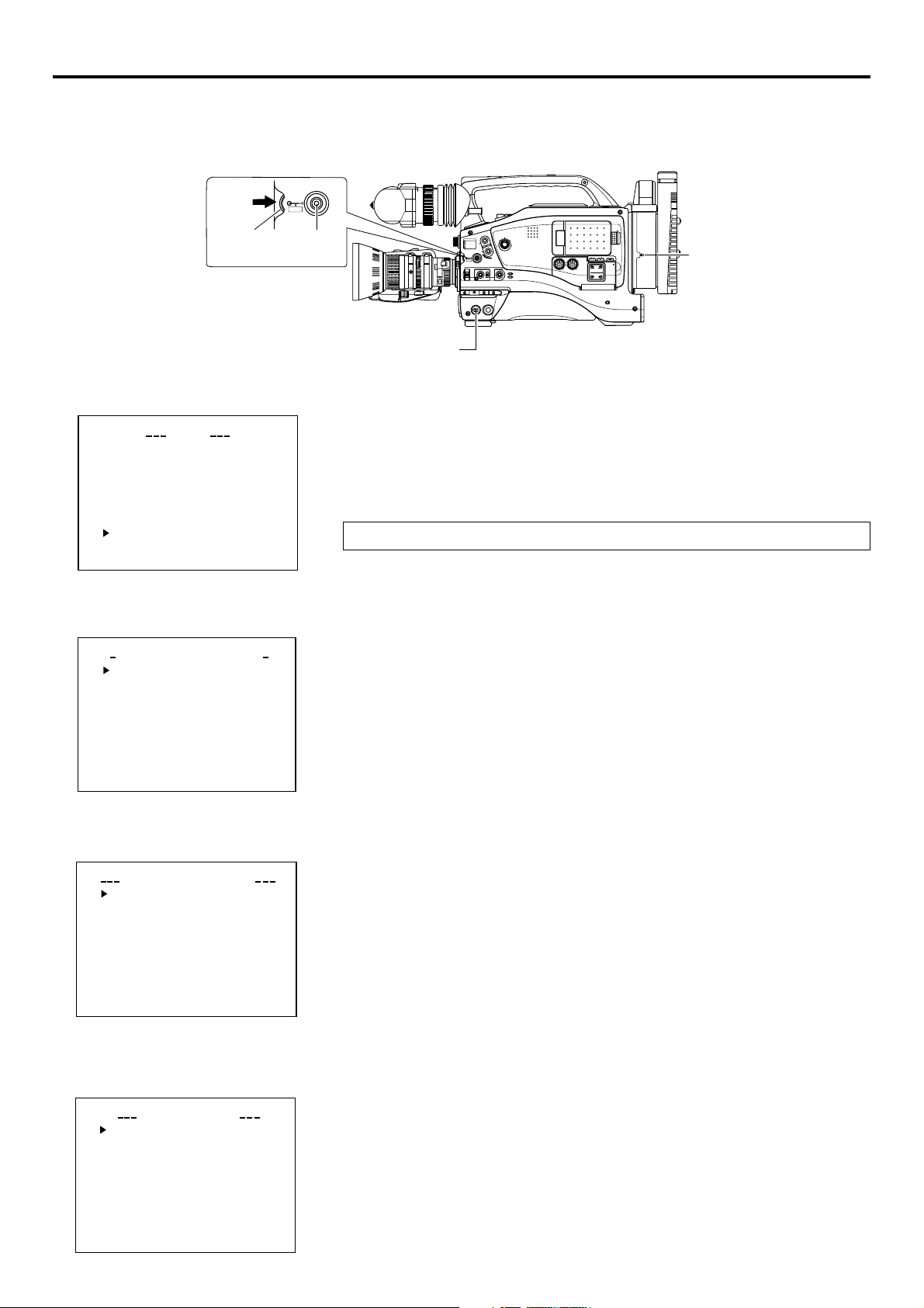
MOVIE CLIP SETUP
menu screen
DELE T E A L L CANCE
FORMAT EXECU
PLAY MODE REPEA
PAGE BACK
IEOVMCLIPET
FORMAT
UP
S
Set to EXECUTE
Flashing display during
formatting
MOVIE CLIP SETUP
menu screen
DELETE ALL CANCE
FORMAT CANCE
PLAY MODE REPEA
PAGE BACK
IEOVMCLIPET
UP
S
L
L
T
L
TE
T
CF memory recording time
Estimated recording time of CF memory cards is shown below:
CF memory
card size
384kbps 256kbps 128kbps ~ 56kbps
BIT RATE
16MByte 3min. 5min. 10min. or more
32MByte 7min. 11min. 20min. or more
64MByte 15min. 22min. 40min. or more
128MByte 30min. 44min. 80min. or more
192MByte 46min. 66min. 120min. or more
256MByte 61min. 88min. 160min. or more
Caution
The actual recording time may differ from the estimate recording time shown above
depending on the recording subject and movement.
18
Page 19

Recording on a CF card
STATUS
SHUTTER
MENU
STATUS button
ZEBRA
OFF
SKIN
AUTO
ON
AREA
WHITE
ACCU
FOCUS
VTR
AUDIO
LEVELE CH-1
5
VTR trigger button
POWER switch
Recording video on a DV cassette tape and CF memory card
EDITSEARCH
MONITOR
FILTER
1
3200K
1
2
8
5600K
ND
/
.3
5600K
1
.4
5600K
/
ND
64
STATUS
SHUTTER
MENU
AUTO IRIS
FULL AUTO BLACK LOLUX
MODE
BACK L
STRETCH
VTR
NORMAL
NORMAL
COMPRESS
SPOT L
CAM
POWER
VTR
ON OFF
MODE switch
VTR trigger button
CH-1 CH-2
OPEN
POWER
SUPPLY
LCD BRIGHT DISPLAY
AUDIO
LEVEL
CH-1
CH-1 CH-2
ON OFF
PULL
OPEN
FRONT
REAR
CH-2
AUDIO INPUT
AUDIO SELECT
AUTO
MANUAL
NETWORK
PACK
KA-DV5000
POWER SUPPLY
switch
MODE
VTR
CAM
● “NO CF FORMAT!” will appear if the in-
serted CF memory card is not formatted.
Format the card in the MOVIE CLIP SET
menu screen. (☞ page 18)
LCD screen
C
F
C
F
䢇
:Red display during
recording
: Initializing
NETWORK PACK CONFIG
menu screen
ORTWENKACK
Pundr8)e
PONCIGF
IMA N
TSE PU
TSE P . .U
P
TSE P . .U
F
(
C
T
C
Vi
RGI
ACNLE
ew
e
)
r
NE T WOR K
ENCODE
MPE G R E C
MOV I ECLI
MENU R ES E T
PAGE BACK
M
(
W
1.
Insert a CF memory card into the Network Pack.
2.
Turn on the GY-DV5000 and KA-DV5000 power.
C
Check to see that the
(When the power is turned on,
3.
Insert a recordable DV cassette tape.
4.
Set the MODE switch to “CAM”. (Light the CAM indicator.)
5.
Set the NETWORK PACK CONFIG menu screen.
F
display appears on the LCD screen/viewfinder screen.
display will flash during initialization.)
q Set MPEG REC to “TRIG”.
w Set the video/audio compression in the ENCODE SETUP menu screen.
(☞ page 6)
e When completed with settings, press the STATUS button to return to the normal
screen.
6.
Press the VTR trigger button on GY-DV5000 to start recording on the DV cassette
tape as well as video/audio streaming data on the CF memory card.
C
● During CF memory card recording, 䢇
7.
To stop recording, press the VTR trigger button.
8.
To resume recording, press the VTR trigger button once more.
9.
To end recording, press the VTR trigger button.
* Before turning off the power, check to make sure the
F
display will light red.
C
F
indicator on the LCD
screen is white.
C
F
Turning the power off when the
indicator is red will damage the recorded clip
file.
ENCODE SETUP menu screen
LCD screen
CF memory card
remaining warning
Set to TRIG
C
F
Memo
● When the DV cassette tape has reached the end during recording, CF memory
card recording will also stop.
● Every time recording is performed, the recorded event is stored in the clip list of
the CF memory card.
Stored contents of clip list: Clip number and date/time when recording was started.
All events can be played back on the MOVIE CLIP screen. (☞ page 23)
● The CF memory card remaining warning is displayed on the LCD screen/viewfinder
screen. (☞ page 46)
● If recording into the CF card is carried out within 5 seconds, either a file cannot be
made or it becomes difficult to display a thumbnail (a still picture displayed when
CLIP FILE is selected).
● Do not switch over the CAM/VTR mode during recording into the CF card. If the
mode is switched over during recording, the display of the LCD viewer can go
wrong once in a while. Also, if the mode is switched over immediately after the
start of recording into the CF card, some black images can be mixed into a recorded picture.
● When recording to a CF Memory Card while in the TRIG mode, ***.csv file will be
created for viewing using the CFViewer.
The CSV file name will be the value of the user's bit (UB) set in GY-DV5000. For
details concerning UB, please refer to the operator’s manual of GY-DV5000.
Time code on CSV files will differ slightly from the actual time code.
19
Page 20

Recording on a CF card Recording video on a CF memory card only
STATUS
SHUTTER
MENU
STATUS button
POWER switch
EDITSEARCH
MONITOR
FILTER
1
3200K
1
2
8
ND
/
5600K
.3
5600K
1
.4
5600K
/
ND
64
STATUS
SHUTTER
MENU
AUTO IRIS
FULL AUTO BLACK LOLUX
MODE
BACK L
STRETCH
VTR
NORMAL
NORMAL
COMPRESS
SPOT L
CAM
POWER
VTR
ON OFF
MODE switch
VTR trigger button
CH-1 CH-2
OPEN
POWER
SUPPLY
LCD BRIGHT DISPLAY
AUDIO
LEVEL
CH-1
CH-1 CH-2
ON OFF
PULL
OPEN
FRONT
REAR
CH-2
AUDIO INPUT
AUDIO SELECT
AUTO
MANUAL
NETWORK
PACK
KA-DV5000
POWER SUPPLY
switch
MODE
VTR
CAM
● “NO CF FORMAT!” will appear if the in-
serted CF memory card is not formatted.
Format the card in the MOVIE CLIP SET
menu screen. (☞ page 18)
LCD screen
C
F
C
F
䢇
: Red display during
recording
: Initializing
NETWORK PACK CONFIG
menu screen
ORTWENKACK
NE T WOR K
ENCODE
MPE G R E C
MOV I ECLI
MENU R ES E T
PAGE BACK
M
Pundr8)e
(
W
PONCIGF
IMA N
TSE P . .U
P
TSE P . .U
(
C
TSE PU
PITL
S
ACNLE
C
ew
e
)
Vi
r
F
1.
Insert a CF memory card into the Network Pack.
2.
Turn on the GY-DV5000 and KA-DV5000 power.
C
Check to see that the
F
display appears on the LCD screen/viewfinder screen.
(When the power is turned on, display will flash during initialization.)
3.
Set the MODE switch to “CAM”. (Light the CAM indicator.)
4.
Set the NETWORK PACK CONFIG menu screen.
q Set MPEG REC to “SPLIT”.
w Set the video/audio compression in the ENCODE SETUP menu screen.
(☞ page 6)
e When completed with settings, press the STATUS button to return to the
normal screen.
5.
Press the VTR trigger button on side panel of GY-DV5000 to start recording stream-
ing data on the CF memory card.
C
● During recording, 䢇
6.
To stop recording, press the VTR trigger button on side panel.
7.
To resume recording, press the VTR trigger button on side panel once more.
8.
To end recording, press the VTR trigger button on side panel.
* Before turning off the power, check to make sure the
F
display will light red.
C
F
indicator on the LCD
screen is white.
ENCODE SETUP menu screen
LCD screen
CF memory card
remaining warning
Set to SPLIT
C
F
Memo
● When recording only to the CF memory card, the clip list will not be registered.
● The CF memory card remaining warning is displayed on the LCD screen/viewfinder
screen. (☞ page 46)
● When MPEG REC is set to “SPLIT”, recording is performed only when the VTR
trigger button on the side is pressed. The VTR trigger buttons on the front and on
the lens are disabled.
● Do not switch over the CAM/VTR mode during recording into the CF card. If the
mode is switched over during recording, the display of the LCD viewer can go
wrong once in a while. Also, if the mode is switched over immediately after the
start of recording into the CF card, some black images can be mixed into a re-
corded picture.
20
Page 21

Recording on a CF card
STATUS
SHUTTER
MENU
EDITSEARCH
FILTER
1
3200K
STATUS button
POWER switch
● “NO CF FORMAT!” will appear if the in-
serted CF memory card is not formatted.
Format the card in the MOVIE CLIP SET
menu screen. (☞ page 18)
1
2
8
5600K
ND
/
.3
5600K
1
.4
/
5600K
ND
64
STATUS
SHUTTER
MENU
AUTO IRIS
FULL AUTO BLACK LOLUX
BACK L
NORMAL
SPOT L
POWER
VTR
ON OFF
VTR trigger button
1.
Insert a CF memory card into the Network Pack.
2.
Turn on the GY-DV5000 and KA-DV5000 power.
Check to see that the
(When the power is turned on,
Recording playback signals of a DV cassette tape on a CF memory card
STILLSTOPREW
MONITOR
MODE
STRETCH
VTR
NORMAL
COMPRESS
CAM
MODE switch
CH-1 CH-2
BLANK SEARCH
OPEN
POWER
SUPPLY
LCD BRIGHT DISPLAY
AUDIO
LEVEL
CH-1
AUDIO INPUT
AUDIO SELECT
CH-1 CH-2
ON OFF
PULL
OPEN
FRONT
REAR
CH-2
AUTO
MANUAL
NETWORK
PACK
KA-DV5000
C
F
display appears on the LCD screen/viewfinder screen.
POWER SUPPLY
switch
MODE
VTR
CAM
FF PLAY
PLAY button
display will flash during initialization.)
LCD screen
C
F
: Red display during
•
recording
: Initializing
NETWORK PACK CONFIG
menu screen
ORTWENKACK
PONCIGF
IMA N
NE T WOR K
ENCODE
MPE G R E C
MOV I ECLI
MENU R ES E T
PAGE BACK
M
Pundr8)e
(
W
TSE P . .U
P
TSE P . .U
TSE PU
F
(
C
S
C
Vi
PITL
ACNLE
ew
3.
Insert the recorded DV cassette tape.
4.
Set the MODE switch to “VTR”. (Light the VTR indicator.)
5.
Set the NETWORK PACK CONFIG menu screen.
C
F
q Set MPEG REC to “SPLIT”.
w Set the video/audio compression in the ENCODE SETUP menu screen.
(☞ page 6)
e When completed with settings, press the STATUS button to return to the normal
screen.
6.
Press the PLAY button of GY-DV5000 to start DV cassette tape playback.
7.
Press the VTR trigger button on side panel at the scene to start recording on the
CF memory card.
C
● During recording, the 䢇
8.
To stop recording, press the VTR trigger button on side panel.
9.
To resume recording, press the VTR trigger button on side panel once more.
10
.
To end recording, press the VTR trigger button on side panel.
e
)
r
* Before turning off the power, check to make sure the
F
display appears in red.
C
F
indicator on the LCD
screen is white.
ENCODE SETUP
menu screen
LCD Screen
CF memory card remaining warning
Set to SPLIT
C
F
Memo
● When recording only to the CF memory card, the clip list will not be registered.
● The CF memory card remaining time is displayed on the LCD screen/viewfinder
screen.
● Do not switch over the CAM/VTR mode during recording into the CF card. If the
mode is switched over during recording, the display of the LCD viewer can go
wrong once in a while. Also, if the mode is switched over immediately after the
start of recording into the CF card, some black images can be mixed into a re-
corded picture.
● While recording DV input to a CF Memory Card in the SPLIT mode, do not oper-
ate the VTR section. Recording to the CF Memory Card may stop as a result.
21
Page 22

Recording on a CF card Deleting all clip files on a CF memory card
MOVIE CLIP SETUP of the NETWORK PACK CONFIG menu screen is used to delete all clips on a CF memory card.
STATUS
SHUTTER
MENU
SHUTTER
dial
STATUS
button
POWER switch
FILTER
1
3200K
2
5600K
.3
5600K
.4
5600K
SHUTTER
MENU
AUTO IRIS
1
8
ND
/
1
/
ND
64
STATUS
FULL AUTO BLACK LOLUX
BACK L
NORMAL
SPOT L
POWER
ON OFF
EDITSEARCH
MONITOR
MODE
STRETCH
VTR
NORMAL
COMPRESS
CAM
VTR
CH-1 CH-2
OPEN
POWER
SUPPLY
LCD BRIGHT DISPLAY
AUDIO
LEVEL
CH-1
AUDIO SELECT
CH-1 CH-2
ON OFF
PULL
OPEN
FRONT
REAR
CH-2
AUDIO INPUT
AUTO
MANUAL
NETWORK
PACK
KA-DV5000
POWER SUPPLY
switch
NETWORK PACK CONFIG
menu screen
ORTWENKACK
NE T WOR K
ENCODE
MPE G R EC
MOV I ECLI
MENU R E S E T
PAGE BACK
M
Pundr8)e
(
W
PONCIGF
IMA N
TSE PU
TSE P . .U
P
TSE P . .U
(
C
RGI
T
ACNLE
C
F
Vi
ew
MOVIE CLIP SETUP
menu screen
DELETE ALL EXECU
FORMAT CANCE
PLAY MODE REPEA
PAGE BACK
IEOVMCLIPET
UP
S
Set to EXECUTE
Deleting
e
TE
L
T
1.
Insert an already recorded CF memory card.
2.
Turn on the GY-DV5000 and KA-DV5000 power.
C
Check to see that the
F
display appears on the LCD screen/viewfinder screen.
(The mark will flash when first turning on the power or during initialization.)
3.
)
r
Press the STATUS button for about 1 seconds to display the TOP MENU screen.
4.
Use the SHUTTER dial to select NETWORK PACK CONFIG menu screen ¥
MOVIE CLIP SETUP menu screen.
5.
Set DELETE ALL in the MOVIE CLIP SETUP menu screen to “EXECUTE” and
press the SHUTTER dial.
● Deletion is executed and “DELETE..” appears flashing on the screen.
6.
When deletion is completed, to the MOVIE CLIP SETUP menu screen returns.
DELETE ALL setting will return to “CANCEL”.
7.
\ To return to the NETWORK CONFIG menu screen, select PAGE BACK and
press the SHUTTER dial.
\ To return to the normal screen, press the STATUS button.
Memo
● Protected clips are not deleted.
DELETE ALL EXECU
FORMAT CANCE
PLAY MODE REPEA
PAGE BACK
IEOVMCLIPET
UP
S
DE L E E..T
MOVIE CLIP SETUP
menu screen
DELETE ALL CANCE
FORMAT CANCE
PLAY MODE REPEA
PAGE BACK
IEOVMCLIPET
UP
S
TE
L
T
L
L
T
22
Page 23

Movie clip Playing back video/audio recorded on a CF memory card
When simultaneously recording the camera video to a DV cassette and CF memory card, recording event will be registered to the clip
list of the CF memory card each time recording is performed. The clip list is stored with the recorded event number (clip number) and the
date/time when the recording was started. All events (clip numbers) can be played back on the MOVIE CLIP screen.
STATUS
SHUTTER
MENU
SHUTTER
dial
STATUS
button
POWER switch
● MOVIE CLIP will not appear during card
initialization (flashing
TOP MENU screen
AUD I O / V I DEO ..
LCD / VF . .
TC / UB / CLOCK . .
OTHERS . .
FILE MAN E. .AG
MENU A LL R E S E T C E LAN C
NETWORKPACKCONFIG
MOVIE CL IP. .
EXIT
display).
MENU
..
Memo
When a MOVIE CLIP menu item is se-
lected and the SHUTTER dial is pressed
with no clips recorded on the CF memory
card, “NO CLIP!” will flash for about 3
seconds.
If there is no CF memory card inserted,
“NO CF CARD!” will flash for about 3
seconds.
CLIP FUNCTION screen
L
IEOVMCIP
mc 0 0 8.0asf WR/
REV I E
W
DELET
E
PROTEC
PAGE BACK
Selected clip number
T
Still image (starting point)
of the selected clip
BLANK SEARCH
EDITSEARCH
MONITOR
FILTER
1
3200K
1
2
8
5600K
ND
/
.3
5600K
1
.4
5600K
/
ND
64
STATUS
SHUTTER
MENU
AUTO IRIS
FULL AUTO BLACK LOLUX
BACK L
NORMAL
SPOT L
POWER
ON OFF
MODE
STRETCH
VTR
NORMAL
COMPRESS
CAM
VTR
CH-1 CH-2
MODE switch
1.
Insert an already recorded CF memory card.
2.
Turn on the GY-DV5000 and KA-DV5000 power.
Check to see that the
(When the power is turned on,
3.
Set the MODE switch to “VTR”. (Light the VTR indicator.)
4.
Make sure GY-DV5000 is not in operation.
5.
Display the MOVIE CLIP screen.
OPEN
POWER
SUPPLY
LCD BRIGHT DISPLAY
AUDIO
LEVEL
CH-1
AUDIO SELECT
CH-1 CH-2
ON OFF
PULL
OPEN
FRONT
REAR
CH-2
AUDIO INPUT
AUTO
MANUAL
NETWORK
PACK
KA-DV5000
MODE
C
F
display appears on the LCD screen/viewfinder screen.
REW button
POWER SUPPLY
switch
VTR
CAM
display will flash during initialization.)
FF PLAY
FF button
STILLSTOPREW
q Press the STATUS button for about 1 seconds to display the TOP MENU screen.
w Turn the SHUTTER dial, move the cursor (t) to MOVIE CLIP and press the
SHUTTER dial.
● The movie clip list of the latest clip page recorded on the CF memory card
and the still image (starting point) of the latest clip number appear by overlapping.
MOVIE CLIP screen
The clip page in the
Clip number
Date/time
Cursor
Latest clip
6.
Select the clip to play back.
mc 0 0 5.0asf WR/
02 03/02/
mc 0 0 6.0asf WR/
02 03/02/
mc 0 0 7.0asf WR/
02 03/02/
mc 0 0 8.0asf WR/
02 03/02/
PAGE BACK
IEOVMCIP
09 0 0:00:
09 3 0:25:
10 1 0:55:
11 0 0:00:
MOVIE CLIP screen dis-
plays 4 lists per page.
L
q Turn the SHUTTER dial and move the cursor (t) to the clip to play back.
● Turning the SHUTTER dial up scrolls to the page with smaller (older) clip
numbers.
● Turning the SHUTTER dial down scrolls to the page with larger (newer) clip
numbers.
● Press the [FF] button to scroll to the next page. Press the [REW] button to
scroll to the previous page.
● Press and hold the [FF] button for about 2 seconds to scroll to the page with
the newest clip.
● Press and hold the [REW] button for about 2 seconds to scroll to the page
with the oldest clip.
w Press the SHUTTER dial.
CLIP FUNCTION screen of the selected clip appears.
● Still image (starting point) of the selected clip appears.
Note
● ASF files recorded using another device may not play back properly on this unit.
● If recording into the CF card is carried out within 5 seconds, either a file cannot be
made or it becomes difficult to display a thumbnail (a still picture displayed when
CLIP FILE is selected).
23
→
OVER
Page 24

Movie clip Playing back video/audio recorded on a CF memory card
CLIP FUNCTION screen
STATUS
L
IEOVMCIP
mc 0 0 8.0asf WR/
SHUTTER
dial
SHUTTER
MENU
REV I E
W
DELET
E
PROTEC
PAGE BACK
T
REVIEW
PAGE BACK
L
IEOVMCIP
mc 0 0 8.0asf WR/
PLAY
PAGE BACK
85k
The BIT RATE used for
Memo
recording is displayed.
● The video encoded by the KA-DV5000
is so designed that it is displayed in a
correct aspect ratio by personal
computer monitor. When the CF
played-back video is viewed by videoout connector output of the GY-DV5000
or observed on a liquid crystal monitor
screen, the aspect ratio may look
different. This is because a simple
output is made on the video for a
personal computer and is therefore
normal and not a malfunction.
● When PLAY MODE in the MOVIE CLIP
SETUP screen is set to “REPEAT”, repeat playback is performed. (☞ page 7)
FF PLAY
PLAY button
STILLSTOPREW
7.
Play back the clip.
1
3200K
2
5600K
.3
5600K
.4
5600K
SHUTTER
AUTO IRIS
FILTER
1
1
MENU
BACK L
NORMAL
SPOT L
ON OFF
EDITSEARCH
8
ND
/
/
ND
64
STATUS
FULL AUTO BLACK LOLUX
POWER
BLANK SEARCH
MONITOR
MODE
STRETCH
VTR
NORMAL
COMPRESS
CAM
VTR
CH-1 CH-2
OPEN
POWER
SUPPLY
LCD BRIGHT DISPLAY
AUDIO
LEVEL
CH-1
CH-1 CH-2
ON OFF
PULL
OPEN
FRONT
REAR
CH-2
AUDIO INPUT
AUDIO SELECT
AUTO
MANUAL
NETWORK
PACK
KA-DV5000
REW button
FF button
Turn the SHUTTER dial, move the cursor to REVIEW and press the SHUTTERdial.
● The movie clip is played back after the clip no. flashes. The value of the recorded
pixel size (320 × 240 or 160 × 120) appears during displaying the still image. The
value of the recorded max. bit rate appears during playback.
8.
To pause playback, press the PLAY button.
9.
To resume playback, press the PLAY button once more.
10
.
The following operations are performed when the playback of the selected clip
ends. (When PLAY MODE in the MOVIE CLIP SETUP screen is set to “OFF”)
● When there are no following clips, the unit pauses at the beginning of the current
clip.
● If following clips exist, the clip no. flashes and then playback is performed.
When all remaining clips are played back, the unit pauses at the beginning of the
played back clip.
\ Selecting PAGE BACK during playback or pausing and press the SHUTTER dial
will return to the MOVIE CLIP screen.
To move to another clip during playback
● Playback will remain on the current clip
even when the FF button is pressed if the
latest clip is being played back.
● Pressing the REW button during play back
of the oldest clip will start playback at the
starting point of the that clip.
\ To move to the next clip during middle of playback or pausing, press the FF
button of GY-DV5000.
● The playback of the current clip stops and the unit pauses at the starting point of the
next clip.
Pressing the FF button again pauses at the starting point of the following the next
clip.
\ To move to the previous clip during middle of playback or pausing, press the
REW button of GY-DV5000.
● The playback of the current clip stops and the unit pauses at the starting point of
the previous clip.
Pressing the REW button again pauses at the starting point of the clip before the
previous clip.
\ To move to the latest clip during middle of playback or pausing, press the FF
button of GY-DV5000 for more than 2 seconds.
● The unit pauses at the starting point of the latest clip.
To start playback, press the PLAY button.
\ To move to the oldest clip during middle of playback or pausing, press the REW
button of GY-DV5000 for more than 2 seconds.
● The unit pauses at the starting point of the oldest clip.
To start playback, press the PLAY button.
24
Page 25

Movie clip Protecting a clip file on a CF memory card
Clips recorded on a CF memory card can be protected using the MOVIE CLIP screen.
STATUS
SHUTTER
MENU
SHUTTER
dial
STATUS
button
EDITSEARCH
MONITOR
FILTER
1
3200K
1
2
8
5600K
ND
/
.3
5600K
1
.4
5600K
/
ND
64
STATUS
SHUTTER
MENU
AUTO IRIS
BACK L
NORMAL
SPOT L
ON OFF
POWER
FULL AUTO BLACK LOLUX
STRETCH
NORMAL
COMPRESS
VTR
MODE
VTR
CAM
CH-1 CH-2
POWER switch MODE switch
OPEN
POWER
SUPPLY
LCD BRIGHT DISPLAY
AUDIO
LEVEL
CH-1
CH-1 CH-2
ON OFF
PULL
OPEN
FRONT
REAR
CH-2
AUDIO INPUT
AUDIO SELECT
AUTO
MANUAL
NETWORK
PACK
KA-DV5000
POWER SUPPLY
switch
MODE
VTR
CAM
● When executing FORMAT in the MOVIE
CLIP SETUP menu screen, protected
clips will also be deleted.
● Protected clips will not be deleted even
when executing DELETE ALL in the
MOVIE CLIP SETUP menu screen.
TOP MENU screen
AUD I O / V I DEO ..
LCD / VF . .
TC / UB / CLOCK . .
OTHERS . .
FILE MAN E. .AG
MENU A LL R E S E T C E LANC
NETWORKPACKCONFIG
MOVIE CL IP. .
EXIT
Clip number
mc 0 0 5.0asf WR/
mc 0 0 6.0asf WR/
mc 0 0 7.0asf WR/
mc 0 0 8.0asf WR/
PAGE BACK
MENU
MOVIE CLIP screen
L
IEOVMCIP
02 03/02/
02 03/02/
02 03/02/
02 03/02/
09 0 0:00:
09 3 0:25:
10 1 0:55:
11 0 0:00:
..
1.
Insert an already recorded CF memory card.
2.
Turn on the GY-DV5000 and KA-DV5000 power.
C
Check to see that the
F
display appears on the LCD screen/viewfinder screen.
(When the power is turned on, display will flash during initialization.)
3.
Set the MODE switch to “VTR”. (Light the VTR indicator.)
4.
Make sure GY-DV5000 is not in operation.
5.
Display the MOVIE CLIP screen.
q Press the STATUS button for about 1 seconds to display the TOP MENU screen.
w Turn the SHUTTER dial, move the cursor (t) to MOVIE CLIP and press the
SHUTTER dial.
● The latest page of the MOVIE CLIP screen appears.
R/W display appears on the right of the clip number.
6.
Select the clip to protect.
Turn the SHUTTER dial, move the cursor (t) to the clip to protect and press the
SHUTTER dial.
● The CLIP FUNCTION screen of the selected clip appears.
7.
Turn the SHUTTER dial, move the cursor to PROTECT in the CLIP FUNCTION
screen and press the SHUTTER dial.
CLIP FUNCTION screen
L
IEOVMCIP
mc 0 0 5.0asf R
● The selected clip is protected.
The R/W display on the right of the clip
number will change to an R display.
Protected
REV I E
W
DELE
T
E
PROTECT
PAGE BACK
CLIP FUNCTION screen
L
IEOVMCIP
mc 0 0 5.0asf WR/
REV I E
W
DELE
T
E
PROTECT
PAGE BACK
8.
To return to the MOVIE CLIP screen after completing setting, select PAGE BACK
and press the SHUTTER dial.
\ To cancel the protection, select PROTECT in the CLIP FUNCTION screen and
press the SHUTTER dial.
● The R display will change to an R/W display and the protection on the clip will be
canceled.
25
Page 26

Movie clip Deleting a clip file on a CF memory card
Clips recorded on a CF memory card can be deleted using the MOVIE CLIP screen.
STATUS
SHUTTER
MENU
SHUTTER
dial
STATUS
button
POWER switch
FILTER
1
3200K
2
5600K
.3
5600K
.4
5600K
SHUTTER
MENU
AUTO IRIS
ON OFF
EDITSEARCH
1
8
ND
/
1
/
ND
64
STATUS
FULL AUTO BLACK LOLUX
BACK L
NORMAL
SPOT L
POWER
VTR
MONITOR
MODE
STRETCH
VTR
NORMAL
COMPRESS
CAM
MODE switch
CH-1 CH-2
OPEN
POWER
SUPPLY
LCD BRIGHT DISPLAY
AUDIO
LEVEL
CH-1
CH-1 CH-2
ON OFF
PULL
OPEN
FRONT
REAR
CH-2
AUDIO INPUT
AUDIO SELECT
AUTO
MANUAL
NETWORK
PACK
KA-DV5000
POWER SUPPLY
switch
MODE
VTR
CAM
TOP MENU screen
AUD I O / V I DEO ..
LCD / VF . .
TC / UB / CLOCK . .
OTHERS . .
FILE MAN E. .AG
MENU A LL R E S E T C E LAN C
NETWORKPACKCONFIG
MOVIE CL IP. .
EXIT
MENU
MOVIE CLIP screen
L
mc 0 0 5.0asf WR/
02 03/02/
mc 0 0 6.0asf WR/
02 03/02/
mc 0 0 7.0asf WR/
02 03/02/
mc 0 0 8.0asf WR/
02 03/02/
PAGE BACK
IEOVMCIP
09 0 0:00:
09 3 0:25:
10 1 0:55:
11 0 0:00:
CLIP FUNCTION screen
L
IEOVMCIP
mc 0 0 8.0asf WR/
1.
Insert an already recorded CF memory card.
2.
Turn on the GY-DV5000 and KA-DV5000 power.
C
Check to see that the
F
display appears on the LCD screen/viewfinder screen.
(When the power is turned on, display will flash during initialization.)
..
3.
Set the MODE switch to “VTR”. (Light the VTR indicator.)
4.
Make sure GY-DV5000 is not in operation.
5.
Display the MOVIE CLIP screen.
q Press the STATUS button for about 1 seconds to display the TOP MENU screen.
w Turn the SHUTTER dial, move the cursor (t) to MOVIE CLIP and press
the SHUTTER dial.
● The latest page of the MOVIE CLIP screen appears.
6.
Select the clip to delete.
Turn the SHUTTER dial, move the cursor (t) to the clip to delete and press the
SHUTTER dial.
● The CLIP FUNCTION screen of the selected clip appears.
7.
Turn the SHUTTER dial, move the cursor to DELETE in the CLIP FUNCTION
screen and press the SHUTTER dial.
● A “DELETE OK?” confirmation message appears. (Confirmation screen)
8.
To delete, select YES using the SHUTTER dial and press the SHUTTER dial.
● “DELETE . .” flashes on the screen for about 5 seconds and then the MOVIE
CLIP screen returns. The clip is deleted from the MOVIE CLIP screen.
REV I E
W
DELET
E
PROTEC
PAGE BACK
T
Confirmation screen
L
IEOVMCIP
mc 00 8.0asf WR/
D
ELETEOK
DELET
?
..
E
PAGE BACK
Deleting Flashing display
Memo
● Protected clips cannot be deleted even when selecting DELETE.
In this case, “PROTECT!” will flash for about 2 seconds and then CLIP FUNC-
TION screen returns.
● After deleting a clip and there are no remaining clips left on the CF memory card,
“NO CLIP!” flashes on the screen for about 3 seconds and then the TOP MENU
screen returns.
● To delete all clips, use the MOVIE CLIP SET in the NETWORK PACK CONFIG
menu screen. (☞ page 22)
26
Page 27

Movie clip Playing back CF memory card clips on your PC
EDITSEARCH
MONITOR
FILTER
1
3200K
1
2
8
ND
/
5600K
.3
5600K
1
.4
/
ND
64
5600K
STATUS
SHUTTER
MENU
AUTO IRIS
BACK L
NORMAL
SPOT L
ON OFF
POWER
FULL AUTO BLACK LOLUX
STRETCH
NORMAL
COMPRESS
VTR
MODE
VTR
CAM
CH-1 CH-2
Clips recorded on a CF memory card can be played back on your PC.
OPEN
POWER
SUPPLY
LCD BRIGHT DISPLAY
AUDIO
LEVEL
CH-1
AUDIO SELECT
CH-1 CH-2
ON OFF
PULL
OPEN
FRONT
REAR
CH-2
AUDIO INPUT
AUTO
MANUAL
NETWORK
KA-DV5000
CF memory
PACK
card
CF Card reader
* If the PC is equipped with PCMCIA
slot(s), CF card reader is not required.
Caution
● Clips recorded on CF memory cards are stored in ASF file format.
● To play back a clip on your PC, Windows Media Player 7.01 is required. (WM9 is not supported.)
* Windows Media Player is compatible with Windows XP or Windows 2000/98(SE)/Me operating system.
* Media Player can be downloaded from the Microsoft Website.
During this time, download the following codec software as well.
The codec software is automatically downloaded when opening the clip file and running Windows Media Player.
• Video codec (decorder) ISO MPEG4
• Audio codec (decorder) G.726
Operation
1.
Load data already recorded on a CF memory card to your PC using a CF card reader, etc.
2.
Launch Explorer, etc., and open the recorded clip file in ASF format.
● Windows Media Player launches and the clip is played back.
Memo
Video and audio files (clip files) in CF memory cards can be appended to email as attachment files.
27
Page 28

LAN card Sending video using LAN card while recording on a DV cassette tape
STATUS
SHUTTER
MENU
STATUS button
ZEBRA
OFF
SKIN
AUTO
ON
AREA
WHITE
ACCU
FOCUS
VTR
AUDIO
LEVELE CH-1
5
VTR trigger button
POWER switch
EDITSEARCH
MONITOR
FILTER
1
3200K
1
2
8
5600K
ND
/
.3
5600K
1
.4
5600K
/
ND
64
STATUS
SHUTTER
MENU
AUTO IRIS
FULL AUTO BLACK LOLUX
MODE
BACK L
STRETCH
VTR
NORMAL
NORMAL
COMPRESS
SPOT L
CAM
POWER
VTR
ON OFF
MODE switch
VTR trigger button
CH-1 CH-2
OPEN
POWER
SUPPLY
LCD BRIGHT DISPLAY
AUDIO
LEVEL
CH-1
CH-1 CH-2
ON OFF
PULL
OPEN
FRONT
REAR
CH-2
AUDIO INPUT
AUDIO SELECT
AUTO
MANUAL
NETWORK
PACK
KA-DV5000
POWER SUPPLY
switch
MODE
VTR
CAM
LCD screen
e
LAN card display
No LAN card is inserted when the display
appears. Turn off the power and insert a LAN
card. Then, turn the power back on.
NETWORK PACK CONFIG
menu screen
ORTWENKACK
NE T WOR K
ENCODE
MPE G R EC
MOV I ECLI
MENU R E S E T
PAGE BACK
M
Pundr8)e
(
W
PONCIGF
IMA N
TSE PU
TSE P . .U
P
TSE P . .U
F
(
C
T
C
Vi
R
ACNGILE
ew
e
)
r
1.
Insert a LAN card into the Network Pack.
2.
Turn on the GY-DV5000 and KA-DV5000 power.
Check to see that the LAN card display is showing on the LCD screen/viewfinder
screen.
3.
Set the MODE switch to “CAM”. (Light the CAM indicator.)
4.
Insert a recordable DV cassette tape.
● GY-DV5000 will be in the standby mode.
5.
Set the NETWORK PACK CONFIG menu screen.
q Set MPEG REC to “TRIG”.
w Set the video/audio compress in the ENCODE SETUP menu screen. (☞ page 6)
• When playing back video/audio streaming data using Quick Time, set STREAM
TYPE in the ENCODE SETUP menu to “for QT”.
e When completed, press the STATUS button to return to the normal screen.
6.
When pressing the VTR trigger button of GY-DV5000 while Streamproducer is in
operation*, transmission of video/audio streaming data from the LAN card is started
simultaneously with recording to DV cassette tape.
● The LAN card display on the LCD screen/viewfinder screen will be as follows:
䢇
: Red display during data transmission.
e
* Perform setting described in “5-2 Operating video from DV camcorder • Trigger
mode function” of network distribution software “Streamproducer” User’s Guide.
ENCODE SETUP menu screen
Set to TRIG
7.
To stop transmission or recording, press the VTR trigger button.
● GY-DV5000 will be in the standby mode.
8.
To resume transmission or recording, press the VTR trigger button once more.
9.
To end, press the VTR trigger button to stop transmission and recording and turn
off the power.
Lastly, remove the LAN card.
Memo
● Streaming data will be sent from the LAN card even when a DV cassette tape is
not inserted.
● When the DV cassette tape reaches the end during recording, the transmission
of streaming data from the LAN card is also stopped.
28
Page 29

LAN card Sending video using a LAN card (no DV cassette tape recording)
STATUS
SHUTTER
MENU
STATUS button
POWER switch
EDITSEARCH
MONITOR
FILTER
1
3200K
1
2
8
5600K
ND
/
.3
5600K
1
.4
5600K
/
ND
64
STATUS
SHUTTER
MENU
AUTO IRIS
FULL AUTO BLACK LOLUX
MODE
BACK L
STRETCH
VTR
NORMAL
NORMAL
COMPRESS
SPOT L
CAM
POWER
VTR
ON OFF
MODE switch
VTR trigger button
CH-1 CH-2
OPEN
POWER
SUPPLY
LCD BRIGHT DISPLAY
AUDIO
LEVEL
CH-1
AUDIO INPUT
AUDIO SELECT
CH-1 CH-2
ON OFF
PULL
OPEN
FRONT
REAR
CH-2
AUTO
MANUAL
NETWORK
PACK
KA-DV5000
POWER SUPPLY
switch
MODE
VTR
CAM
LCD screen
e
LAN card display
No LAN card is inserted when the display
appears. Turn off the power and insert a LAN
card. Then, turn the power back on.
NETWORK PACK CONFIG
menu screen
ORTWENKACK
NE T WOR K
ENCODE
MPE G R EC
MOV I ECLI
MENU R E S E T
PAGE BACK
M
Pundr8)e
(
W
PONCIGF
IMA N
TSE PU
TSE P . .U
P
TSE P . .U
(
C
F
PILT
S
ACNLE
C
Vi
ew
e
)
r
1.
Insert a LAN card into the Network Pack.
2.
Turn on the GY-DV5000 and KA-DV5000 power.
Check to see that the LAN card display is showing on the LCD screen/viewfinder
screen.
3.
Set the MODE switch to “CAM”. (Light the CAM indicator.)
4.
Set the NETWORK PACK CONFIG menu screen.
q Set MPEG REC to “SPLIT”.
w Set the video/audio compress in the ENCODE SETUP menu screen. (☞ page 6)
• When playing back video/audio streaming data using Quick Time, set STREAM
TYPE in the ENCODE SETUP menu to “for QT”.
e When completed, press the STATUS button to return to the normal screen.
5.
When operating Streamproducer and making network connection with KA-DV5000,
sending of streaming video/audio data will start from the LAN card.
When pressing the VTR trigger button on the side of GY-DV5000, recording to the
HDD will start.
● The LAN card display on the LCD screen/viewfinder screen will be as follows:
䢇
: Red display during data transmission.
e
* Perform setting described in “5-2 Operating video from DV camcorder • Trigger
mode function” of network distribution software “Streamproducer” User’s Guide.
ENCODE SETUP
menu screen
Set to SPLIT
6.
To stop recording to the HDD, press the VTR trigger button on the side.
7.
Press the VTR trigger button on the side to resume recording to the HDD.
8.
To end operation, stop the transmission by disconnecting the network connection
with KA-DV5000 using Streamproducer, then turn off the power.
Lastly, remove the LAN card.
Memo
● When MPEG REC is set to “SPLIT”, sending is performed only when the VTR
trigger button on the side is pressed. The VTR trigger buttons on the front and on
the lens are disabled.
● Pressing the VTR trigger button on the side does not record the camera image
onto the inserted DV cassette tape.
29
Page 30

LAN card Sending playback signals of a DV cassette tape using a LAN card
STATUS
SHUTTER
MENU
SHUTTER
dial
STATUS
button
POWER switch
LCD screen
e
LAN card display
No LAN card is inserted when the display
appears on. Turn off the power and insert a LAN
card. Then, turn the power back on.
NETWORK PACK CONFIG
menu screen
STILLSTOPREW
PLAY button
1
3200K
2
5600K
.3
5600K
.4
5600K
SHUTTER
AUTO IRIS
FILTER
1
/
1
/
MENU
BACK L
NORMAL
SPOT L
POWER
ON OFF
EDITSEARCH
8
ND
ND
64
STATUS
FULL AUTO BLACK LOLUX
STRETCH
NORMAL
COMPRESS
VTR
MONITOR
MODE
VTR
CAM
MODE switch
CH-1 CH-2
BLANK SEARCH
OPEN
POWER
LCD BRIGHT DISPLAY
AUDIO
LEVEL
CH-1
AUDIO INPUT
AUDIO SELECT
CH-1 CH-2
SUPPLY
ON OFF
PULL
OPEN
FRONT
REAR
CH-2
AUTO
MANUAL
NETWORK
PACK
KA-DV5000
POWER SUPPLY
switch
MODE
VTR
CAM
FF PLAY
VTR trigger button
1.
Insert a LAN card into the Network Pack.
2.
Turn on the GY-DV5000 and KA-DV5000 power.
Check to see that the LAN card display is showing on the LCD screen/viewfinder
screen.
3.
Set the MODE switch to “VTR”. (Light the VTR indicator.)
4.
Insert the recorded DV cassette tape.
5.
Set the NETWORK PACK CONFIG menu screen.
q Set MPEG REC to “SPLIT”.
w Set the video/audio compression in the ENCODE SETUP menu screen.
(☞ page 6)
• When playing back video/audio streaming data using Quick Time, set STREAM
TYPE in the ENCODE SETUP menu to “for QT”.
e When completed with settings, press the STATUS button to return to the normal
screen.
NE T WOR K
ENCODE
MPE G R EC
MOV I ECLI
MENU R E S E T
PAGE BACK
M
Pundr8)e
(
W
ENCODE SETUP
menu screen
ORTWENKACK
PONCIGF
IMA N
TSE PU
TSE P . .U
P
TSE P . .U
RGI
T
C
ACNLE
F
Vi
(
C
ew
6.
When operating Streamproducer and making network connection with KA-DV5000,
sending of streaming video/audio data will start from the LAN card.
● The LAN card display on the LCD screen/viewfinder screen will be as follows:
䢇
: Red display during data transmission.
e
e
)
r
* Perform setting described in “5-2 Operating video from DV camcorder • Trigger
mode function” of network distribution software “Streamproducer” User’s Guide.
7.
Press the PLAY button of GY-DV5000 to start DV cassette tape playback.
SPLIT
8.
Press the VTR trigger button on the side at the scene to start HDD recording with
Streamproducer.
9.
To stop recording to the HDD, press the VTR trigger button on the side.
10
.
Press the VTR trigger button on the side to resume recording to the HDD.
11
.
To end operation, first disconnect the network connection and then turn off the
power. Lastly, remove the LAN card.
30
Page 31

Network pack setup
MONITOR
EDITSEARCH
FILTER
STATUS
SHUTTER
MENU
AUTO IRIS
BACK L
NORMAL
SPOT L
STRETCH
NORMAL
COMPRESS
FULL AUTO BLACK LOLUX
MODE
POWER
ON OFF
VTR
OPEN
VTR
CAM
1
3200K
5600K
5600K
5600K
ND
/
/
ND
2
.3
.4
1
8
1
64
CH-1
AUDIO INPUT
AUDIO SELECT
CH-2
CH-1 CH-2
FRONT
REAR
AUTO
MANUAL
AUDIO
LEVEL
CH-1 CH-2
PULL
OPEN
LCDBRIGHT DISPLAY
NETWORK
PACK
KA-DV5000
POWER
SUPPLY
ONOFF
Controlling GY-DV5000/KA-DV5000 via LAN card
With the Network Pack, GY-DV5000/KA-DV5000 can be controlled via LAN.
It is also possible to playback video and audio from KA-DV5000 on your PC in the STREAMCAPTURE screen in realtime (live display)
as well as save data to files. However, note that video and audio from KA-DV5000 can be played back only on one PC at a time.
Peer-to-peer connection that directly connects the unit with a PC is explained here.
● There are the 3 types of users for Web access:
● Users referred as “jvc” (can be changed) that can
perform all operations, “ENCODE” users that can
view all data but only change the encoding
settings, and “BROWSE” users that can only view
data.
GY-DV5000
10/100 BASE-T
cross cable
PC
Set the LAN card
driver by following
the instructions on
manual provided
by the card
manufacturer.
● The default password for each user type is “ka-
dv5k” for “jvc” users, first 4 characters of the
password set for “jvc” users for “ENCODE” users
(default is “ka-d”) and fixed password of “ka-dv”
for “BROWSER” users.
● The following is an explanation when login is made
a user permitted with all operations. In the case of
other users, the OK button and Cancel button will
be disabled even if operations on the screen are
allowed.
1.
Turn your PC and GY-DV5000 and KA-DV5000 power off.
2.
Insert the PCMCIA LAN card to specify into KA-DV5000.
3.
Connect the unit and PC using a 10/100 BASE-T cross cable.
4.
Turn the PC and GY-DV5000 and KA-DV5000 power on.
5.
Insert a recordable DV cassette tape.
6.
PC settings
● Set the LAN card driver according to the manual provided
by the card manufacturer.
● Network settings (☞ page 14)
q Set the following items in the TCP IP properties:
* DHCP server is not used.
IP address: 192.168.100.101
Subnet mask: 255.255.255.000
w Setting the proxy server.
• Set the proxy server using the “LAN SETTINGS” of
Windows.
• When using peer-to-peer communication that directly
connects the PC and KA-DV5000, deselect the “Use a
proxy server” checkbox.
• When the “Use a proxy server” setting must be enabled due to a LAN environment (in-company LAN,
etc.), click “Advanced...” and input the IP address of
GY-DV5000 in “Exceptions” of the “Use a proxy server”
setting.
(☞ “About proxy servers,” Page 49)
KA-DV5000
Socket Com: EA2900-117 (USA)
EA2903-162 (Europe)
EA2906-194 (Asia)
(CF memory card adapter (PCMCIA TYPE I/II
specifications)(sold separately) is required for
inserting this card.)
8.
Input the user ID and password.
q For the user ID, input “jvc” (factory setting).
For the password, input “ka-dv5k” (factory setting) or the
name set in the SERVER SETUP menu screen.
(☞ page 12)
w Check to make sure the inputted user ID and password
are correct and click the OK icon.
(Check “Save password” so that the password does not
need to be inputted for future accesses.)
9.
If the user ID and password are correct, the NETWORK PACK
SETUP screen appears on the PC monitor.
● GY-DV5000/KA-DV5000 settings and operations can be
controlled using the NETWORK PACK SETUP. (☞ page
32)
Caution
● When setting the NETWORK PACK SETUP screen (CAM &
VTR CONTROL, NETWORK SETUP, PORT SETUP or ENCODE PARAMETERS) and the same menu screen is displayed on the LCD screen or viewfinder of GY-DV5000, values set in the NETWORK PACK SETUP screen will not appear on menu screen of the LCD screen or the viewfinder of
GY-DV5000.
The values set in the NETWORK PACK SETUP screen will
appear after the menu screen of GY-DV5000 is closed once
and reopened.
● During camera/VTR control, noise may be heard from the
speakers. However, this is not a malfunction. If the noise be-
7.
Launch the browser on your PC and enter 192.168.100.101
(default factory setting) in the address bar and press ENTER.
● A confirmation window for user ID and password appears.
comes irritating, open the “Sound & Multimedia” property from
the Windows Control Panel and set the sound of “Windows
Explorer Start Navigation” of “Sound Events” to off.
* For setting details, see Windows’ Help.
Enter Network Password
?X
● Check to make sure that NET REMOTE in the OTHERS [1/2]
menu screen of GY-DV5000 is set to “ON”. Camera control
Please enter tour authentication information.
Resource
User name:
Password:
secured
OK
Cancel
will not be available when NET REMOTE is set to “OFF”.
● Depending on the cache setting of your browser, the param-
eters updated in the Camera menu may not be effective immediately.
Save password?
31
Page 32

Network pack setup NETWORK SETUP screen
Clicking NETWORK SETUP on the left of the Streamcorder screen displays the NETWORK SETUP screen for performing network
related settings.
Screen selection
Clicking the OK icon
will confirm the inputted
setting.
Contact your network administrator for any unclear points concerning network settings.
Item
Address Setup
IP Address
Subnet Mask
Default Gateway
Host Name
Domain Name
DNS Server
FTP Server
Account
AD-HOC MODE
WLAN Channel
ESS-ID
Setting
MANUAL
DHCP
IBSS
AHDM
OFF
1 CH
:
10 CH
:
14 CH
Description Factory setting
The address setting mode can be selected. MANUAL
MANUAL : Select for MANUAL mode.
DHCP : Select for DHCP mode.
The IP address can be set. 192.168.100.101
The subnet mask can be set. 255.255.255.000
The gateway address can be set. 192.168.100.254
The host name can be set. (Max: 63 alphanumerical characters) none
The domain name can be entered. (Max: 63 alphanumerical characters) none
The address of the domain name system server can be set. 0.0.0.0
When selecting Change, settings can be made in the FTP Server
Account Setup screen. (☞ page 33)
The AD-HOC mode can be set. OFF
WLAN Channel can be set. 10 CH
When selecting Change, settings can be made in the ESS-ID Setup
screen. (Max: 32 alphanumerical characters) (☞ page 33)
WEP
WEP Key
LEAP
LEAP Server
Accout
64 Bit
128 Bit
OFF
ON
OFF
WEP is set. OFF
When selecting Change, settings can be made in the WEP Key Setup
screen. (☞ page 33)
When set to ON, LEAP Server Account can be set. OFF
When Change is selected, settings can be made in the LEAP Server
Account Setup screen. (☞ page 33)
Caution
If the IP address is changed in the Streamcorder screen, the unit will automatically jump to the new IP address. However, the
screen may not be displayed correctly depending on the environment. In this case, access by specifying the new IP address using
a browser. (☞ operation 7. on pages 31)
32
Page 33

Network pack setup NETWORK SETUP screen
FTP Server Account Setup screen
Item Description
User Name Input the FTP user name. ftp-user
Old password Input the currently used password. ka-dv
New Password Input the new password.
Confirm New For confirmation, input the new password
again.
Factory
setting
ESS-ID Setup screen
WEP Key Setup screen
Primary ESS-ID
Item Description
Current ESS-ID Input the currently used ESS-ID. NONE
New ESS-ID Input the new ESS-ID.
Confirm New For confirmation, input the new ESS-ID again.
Secondary ESS-ID
Item Description
Current ESS-ID Input the currently used ESS-ID. NONE
New ESS-ID Input the new ESS-ID.
Confirm New For confirmation, input the new ESS-ID again.
Item Description
Current Wep Key Input the currently used Wep Key.
New Wep Key Input the new Wep Key.
Factory
setting
Factory
setting
Factory
setting
LEAP Server Account Setup screen
Confirm New
Item Description
User Name Input the LEAP user name. leap-user
Old Password Input the currently used password. ka-dv-jvc
New Password Input the new password.
Confirm New
33
For confirmation, input the new Wep Key again.
Factory
setting
For confirmation, input the new password again.
Page 34

Network pack setup PORT SETUP screen
Clicking PORT SETUP on the left of the Streamcorder screen displays the PORT SETUP screen for performing port settings.
Screen selection
Item
HTTP (for WEB Browser)
HTTP (for Media Player)
Input
Clicking the OK icon will confirm
the inputted setting.
Description Factory setting
The HTTP port for WEB browser can be set. (1 to 32767) 80
The HTTP port for Media player can be set. (1 to 32767) 8080
RTSP (for Streamproducer)
RTSP (for Quick Time)
* Changing ports require special knowledge. Always consult the administrator of the connecting network when making changes.
* Do not use the same port numbers for RTSP and HTTP.
The Streamproducer RTSP port number can be set. (1 ~ 32767) 8554
Quick Time RTSP port number can be set. (1 ~ 32767) 554
Caution
If the port is changed in the Streamcorder screen, the unit will automatically jump to the new port. However, the screen may not be
displayed correctly depending on the environment. In this case, access by specifying the new port using a browser. (☞ operation
on pages 31)
7.
34
Page 35

Network pack setup CAM & VTR CONTROL screen
When the correct user ID and password are accepted, the following Streamcorder screen appears.
In the CAM & VTR CONTROL screen, camera adjustments of GY-DV5000 and VTR controls can be made.
Screen selection
Clicking will display the
selected screen.
\ Camera Control
Setting range
● When setting AUTO to ON, items other than LOLUX will not be available.
● When setting BARS to ON, items other than AUTO and LOLUX will not be available.
● When setting GAIN to ALC, IRIS and SHUTTER will not be available.
Setting
Select the setting from the
pull-down menu.
Adjustment mode selection
Check the desired
adjustment mode.
Clicking the OK icon will
confirm the inputted
setting.
Item
AUTO
BARS
WHITE BAL
IRIS
Lolux
GAIN
SHUTTER
Adjustment mode
ON: Auto mode on. Items other than LOLUX cannot be set.
OFF: Auto mode off
ON: Color bar signals are outputted. Items other than AUTO and LOLUX cannot be set.
OFF: Color bar signals are not outputted.
FAW: Full white balance mode
PRESET: White balance will be in the preset state. (3200K)
MEMORY A, B: White balance setting stored in the GY-DV5000 memory will be used.
AUTO
MANUAL
ON
OFF
ALC
STEP
0dB
STEP
Auto iris mode. Iris will be adjusted within the following range:
[–3, –2, –1, 0, +1, +2, +3]
Manual iris mode. Iris will be adjusted within the following range:
[CLOSE, F16, F11, F8, F5.6, F4, F2.8, F2, OPEN]
Lolux mode
ALC (Auto Level Control) mode. IRIS and SHUTTER cannot be set
Gain can be set within the following range. 0dB is not available.
[–3dB ~ 18dB]
0dB (Sensitivity is not increased)
Shutter speed can be set within the following range:
U model: [1/7.5, 1/15, 1/30, 1/100, 1/250, 1/500, 1/1000, 1/2000, 1/4000, 1/10000]
E model: [1/6.25, 1/12.5, 1/25, 1/120, 1/250, 1/500, 1/1000, 1/2000, 1/4000/, 1/10000]
Setting/description
OFF
V-SCAN
Shutter speed will be 1/60 (1/50). ( ): for E model
Although this setting can be canceled, future settings of this item will not be allowed.
35
Page 36

Network pack setup CAM & VTR CONTROL screen
\ VTR Control
VTR control icons
Click each button to perform
operation.
\ To control the VTR in the Streamcorder screen, the following menu items of GY-DV5000 must be set in advance.
OTHERS [1/2] menu screen
OTHERS [ 1 / 2 ]
OUTPUT CHAR
NET REMOTE ON
DV REC TR I GER OFF
LONG PAUS E T I ME 3 0M I N
REM F F / REW MODE F F / REW
STEP SLOW MODE FRAME
NEXT PAGE
PAGE
BAC
K
OFF
● Set NET REMOTE in the OTHERS [1/2] menu screen to ON.
When set to OFF, the VTR cannot be controlled from the
Streamcorder screen.
\ VTR control icon operations by MODE switch settings of GY-DV5000 are as follows:
—: Mode will not change
GY-DV5000 state Clicking VTR control icon
MODE switch Previous mode REC REW STOP FF PLAY PAUSE/STILL
VTR STOP REC REW — FF PLAY —
FF — REW STOP — PLAY —
REW ——STOP FF PLAY —
PLAY —
REV SEARCH
STOP
FWD SEARCH
— STILL
STILL ——STOP — PLAY —
CAM STOP REC REW — FF ——
REC ——STOP ——STBY
STBY REC — STOP ———
36
Page 37

Network pack setup ENCODE PARAMETERS screen
Clicking ENCODE PARAMETERS on the left of the Streamcorder screen displays the ENCODE PARAMETERS
screen for performing video/audio compression settings.
Setting
Select the setting from the
pull-down menu.
Screen selection
Click the OK icon to
confirm setting.
Setting range
䢇indicates default factory setting.
Item
Frame Size
Bit Rate
Frame Rate
Setting
䢇 320 × 240
160 × 120
56K (bps)
128K (bps)
256K (bps)
䢇 384K (bps)
512K (bps)
MAX
䢇 MID
MIN
BIT RATE
(bps)
512K
384K
256K
Description
Sets the video compression size.
320 × 240: Sets the image size to 320 × 240 pixels. (CIF)
160 × 120: Sets the image size to 160 × 120 pixels. (QCIF)
(1/4 image size of CIF.)
Sets the video streaming speed.
Sets the frame rate per second. Settings are as shown below.
FRAME SIZE
320 × 240 160 × 120
MAX MID MIN MAX MID MIN
NTSC 15 10 7.5 30 15 10
PAL 12.5 5 5 25 12.5 12.5
NTSC 15 10 7.5 30 15 10
PAL 12.5 5 5 25 12.5 5
NTSC 15 7.5 5 30 15 7.5
PAL 12.5 5 5 25 12.5 5
BIT RATE
(bps)
NTSC 7.5 5 3 15 10 7.5
128K
PAL 5 5 1 12.5 12.5 5
NTSC 3 1 1 10 7.5 5
56K
PAL 1 1 1 12.5 5 5
FRAME SIZE
320 × 240 160 × 120
MAX MID MIN MAX MID MIN
Stream Type
䢇 For Media
Player
For Quick
Time
Sets the player for stream playback.
Memo
• No sound will be heard when playing back using QuickTime while in the WMP mode.
• No sound will be heard when playing back using Media Player while in the QT mode.
• Set to WMP mode when recording to CF memory card.
37
Page 38

Network pack setup
Click the characters “STREAMCAPTURE” on the left of the Streamcorder screen to display the Streamcapture screen shown below.
Video and audio sent from KA-DV5000 via LAN can be played back on your PC in the Streamcapture screen or data can be saved to files.
It can be used on a PC that has Streamproducer installed.
* Since video on the STREAMCAPTURE screen is converted video data, images will take more time to appear than the actual video taken with GY-
DV5000.
STREAMCAPTURE screen (Playing back video/audio using a PC and saving to file)
Video display
The display size can be changed in the
Property dialog box.
(☞ page 41)
Status/Time elapsed display
● The current status is displayed.
VIEWING
CAPTURING
STOP: Playback is stopped.
WAITING: TRIG recording standby.
: Video or audio from KA-DV5000 is being
played back in realtime (live display).
: Video or audio is being saved in your PC.
Operation buttons –– – Clicking will start operation. When on, the
button will light.
VIEW Click to play back or stop video/audio from KA-
DV5000 on your PC. (ON when the Streamcapture
screen is opened.)
CAPTURE Click to save video or audio to a PC.
Default destination
My Document\Streamcorder (\IPAddress)
Saved file name:
The file name based on the capture start time
will be used.
020304 – 153000.asf
Year Month Day Hour Minute Second
CAPTURE-TRIG.
CAST-CAM Click when sending the video/audio from
CAST-BARS
Click when saving the video/audio from
KA-DV5000 to your PC when starting recording
with GY-DV5000. (☞ page 39)
KA-DV5000 to another PC. (☞ page 39)
Click when transmitting color bars rather than video
from KA-DV5000. (Video from KA-DV5000 will be
displayed in the video display of the Streamcapture
screen. Color bars will not be displayed.)
Clicking the button will display the Property
dialog box.
Video display size and the save destination
folder can be changed. (☞ page 41)
CAST-TRIG. Click when sending the video/audio from KA-
DV5000 to another PC when starting recording
with GY-DV5000. (☞ page 39)
MUTE Click to turn on/off the mute setting.
When on, the playback sound will be muted.
38
→
OVER
Page 39

Network pack setup
STREAMCAPTURE screen (Playing back video/audio using a PC and saving to file)
About the Trigger Mode function (TRIG)
The Trigger Mode function can be used to save and transmit video/audio from KA-DV5000 to your PC by synchronizing to the button
operations of GY-DV5000.
NETWORK PACK CONFIG
menu screen
ORTWENKACK
CLIP
u
PONCIGF
AINM
TUP. .SE
TUP. .S)E
FView(C
RGI
T
NE T WOR K T UP . .SE
ENCODE
MPE G R EC
MOV I E
MENU R E S E T C AN CE
PAGE BACK
(WMP nder 8
NETWORK MAIN SETUP menu screen
(☞ page 10)
er
L
)
Setting
1.
Set MPEG REC in the NETWORK PACK CONFIG menu to
“TRIG” or “SPLIT” using steps 1 ~ 9 of page 8.
● TRIG: Records/transmits video/audio streaming data to
your PC at the same time as the recording to the DV cassette tape set in GY-DV5000.
● SPLIT: Records/transmits video/audio streaming data to
your PC regardless of whether the DV cassette is set.
2.
Click the CAPTURE-TRIG./CAST-TRIG. button in the
Streamcapture screen.
● Button lights and the program enters the trigger standby
mode.
Memo
● When the CAPTURE-TRIG. button is on:
Saves the video/audio from KA-DV5000 to your PC by
synchronizing to the button operations of GY-DV5000.
● When the CAST-TRIG. button is on:
Transmits video/audio from KA-DV5000 to another PC
by synchronizing to the button operations of GY-DV5000.
* When saving and transmitting video/audio at the same
time, light both CAPTURE-TRIG. and CAST-TRIG. buttons.
3.
Press the VTR trigger button of GY-DV5000.
● When the MPEG REC item is set to “SPLIT”, only the VTR
trigger button on the side panel is effective.
● A red 䢇
mark appears on the GY-DV5000 LCD screen
e
and recording/sending to the PC starts.
4.
Press the VTR triggerbutton of GY-DV5000 while the red
䢇
mark is displayed.
e
● The
mark on the LCD screen of GY-DV5000 turns
e
white and recording/sending to the PC stops.
CAPTURE-TRIG.
button
ZEBRA
OFF
SKIN
AUTO
ON
AREA
WHITE
ACCU
FOCUS
VTR
AUDIO
LEVELE CH-1
5
CAST-TRIG.
button
EDITSEARCH
MONITOR
FILTER
1
3200K
1
2
8
ND
/
5600K
.3
5600K
1
.4
/
ND
64
5600K
STATUS
SHUTTER
MENU
AUTO IRIS
FULL AUTO BLACK LOLUX
BACK L
STRETCH
NORMAL
NORMAL
SPOT L
COMPRESS
POWER
VTR
ON OFF
OPEN
POWER
SUPPLY
LCD BRIGHT DISPLAY
AUDIO
LEVEL
CH-1 CH-2
MODE
VTR
CAM
CH-1
CH-1 CH-2
ON OFF
PULL
OPEN
FRONT
REAR
CH-2
AUDIO INPUT
AUDIO SELECT
AUTO
MANUAL
NETWORK
PACK
KA-DV5000
VTR trigger button
<GY-DV5000 front>
VTR trigger switch
39
Page 40

Network pack setup
STREAMCAPTURE screen (Playing back video/audio using a PC and saving to file)
About the Cast function (CAST)
The Cast function can be used to send video/audio from KA-DV5000 to another PC.
<Sending method>
Display the video to send in the video display window of the
Streamcapture screen and click the CAST-CAM button.
<Receiving sent video>
Video sent using the Cast function can be received using Win-
dows Media Player.
1.
Launch Windows Media Player and select [Open URL] from
the [File] menu.
CASTCAM
button
CASTBARS
button
CASTTRIG.
button
<Color bar transmission>
When clicking the BARS button, color bars are transmitted rather
than the video from KA-DV5000.
● Video of the receiving side will be displayed with color bars.
(Video from KA-DV5000 will be displayed in the video display of
the Streamcapture screen. Color bars will not be displayed.)
● Click the CAST button to switch back to the transmission of video
from KA-DV5000.
● To stop the transmission of video from KA-DV5000 / color bars,
turn off the CAST-CAM/CAST-BARS button.
In this case, the connection with the receiving side will be dis-
connected.
<Trigger transmission>
When transmitting video/audio from KA-DV5000 to another PC by
synchronizing to the button operations of GY-DV5000, click the
CAST-TRIG. Button. (☞ page 39)
2.
Input the IP address and port number of the PC sending data
using Streamcapture.
* The settings can be checked in "Internet URL" of the Cast
dialog box.
● Internet connection
● LAN connection
3.
Click OK to view the received video.
Caution
When Windows Media Player is receiving a video being sent,
sometimes the connection with a server can be cut off. In such
a case, press the PLAY button of Windows Media Player again.
40
Page 41

Network pack setup
Property dialog box
Click the OK button to
confirm settings.
Save destination folder
The default save destination is as follows:
Set this field when changing the save destina-
tion folder.
My Document\Streamcorder (\IPAddress)
When changing the destination folder, press the
Browse... button and select the desired folder.
The changed destination folder will be the de-
fault folder for future save operations.
STREAMCAPTURE screen (Playing back video/audio using a PC and saving to file)
Select the video display size
Select the display size from the pull-
down menu.
Setting range:
● Real size
● Fit to window
Advanced settings dialog box
Cast dialog box
Click the OK button to confirm
settings.
HTTP port
Port number of the network used when sending
video/audio is set. Normally, no user setting is re-
quired.
Click the OK button to confirm
settings.
Port numbers of the network used on the PC side dur-
ing communication with the network pack are set.
RTSP port: used for handling commands. Use [TCP].
RTP port: used for receiving video data. Use [UDP].
Normally, available ports are automatically searched
and set.
If there are restrictions to the port numbers due to the
LAN environment settings of your PC, consult your
network administrator.
When specifying the port numbers for use, check each
checkbox and input the number in the edit box on the
right.
Max clients
Sent video/audio can be received up to the number
specified in this dialog box.
Internet/LAN URL
When receiving video/audio, the URL displayed here
in entered in Windows Media Player.
Copy Internet URL
Copies Internet URL to clipboard
Copy LAN URL
Copies LAN URL to clipboard
41
Page 42

Others TOP PAGE can be customized
TOP PAGE can be customized as desired.
TOP PAGE created on a PC is uploaded by FTP.
1.
Set the unit so that NETWORK SETUP can be displayed. (☞ page 31)
2.
Create HTML on the PC using a commercially available HTML editor, etc.
Save the created HTML file under the name of “index.html”.
3.
Use a commercially available FTP program on the PC to upload index.html created in step 2 above to KA-DV5000.
FTP program settings (Execute using the set value.)
IP Adress : 192.168.100.101
Remort Port : 21
USER ID : ftp-user
PASSWORD : ka-dv
\ It is also possible to upload link pages from index.html, images, etc.
Caution
● Make sure the uploaded files do not exceed 100KB in total.
● The HTML display will fit properly on the screen when creating at a size of about 500 × 360 pixels.
● Once uploaded, the file is overwritten and cannot be reproduced. Download and backup necessary files in the FTP.
42
Page 43

Others Connecting Windows Media Player
Connect the KA-DV5000 to Windows Media Player using the network.
1.
Set STREAM TYPE in the ENCODE SETUP menu to “for WMP”.
2.
Open Windows Media Player.
3.
Select [File] → [Open URL].
The following dialog box will appear.
4.
Set the IP address of the camera.
http://***.***.***.***:####/asf
* → IP address of camera
# → HTTP Port number set in “for Media player”
5.
When completed with setting, select OK to establish connection.
Memo
● WMP for Mac OS not supported.
Use QuickTime Player. (☞ page 44)
43
Page 44

Others Connecting Quick Time Player
Connect the KA-DV5000 to QuickTime Player using the network.
1.
Set STREAM TYPE in the ENCODE SETUP menu to “for QT”.
2.
Open Quick Time Player.
3.
Select [File] → [Open URL with New Player].
The following dialog box will appear.
4.
Set the IP address of the camera.
rtsp://***.***.***.***/live.mp4
* → IP address of camera
5.
When completed with setting, select OK to establish connection.
44
Page 45

Others About updating the network pack
The network pack firmware version can be updated.
For details concerning version update data, visit the JVC homepage.
STATUS
SHUTTER
dial
SHUTTER
MENU
STATUS
button
POWER switch
FILTER
1
3200K
2
5600K
.3
5600K
.4
5600K
SHUTTER
MENU
AUTO IRIS
BACK L
NORMAL
SPOT L
ON OFF
1
8
ND
/
1
/
ND
64
STATUS
POWER
EDITSEARCH
FULL AUTO BLACK LOLUX
STRETCH
NORMAL
COMPRESS
VTR
BLANK SEARCH
MONITOR
MODE
VTR
CAM
CH-1 CH-2
OPEN
POWER
SUPPLY
LCD BRIGHT DISPLAY
AUDIO
LEVEL
CH-1
AUDIO SELECT
CH-1 CH-2
ON OFF
PULL
OPEN
FRONT
REAR
CH-2
AUDIO INPUT
AUTO
MANUAL
NETWORK
PACK
KA-DV5000
POWER SUPPLY
switch
FF PLAY
STOP button
STILLSTOPREW
NETWORK PACK CONFIG menu screen
ORTWENKACK
NE T WOR K
ENCODE
MPE G R EC
MOV I ECLI
MENU R E S E T
UPDA ET..
PAGE BACK
M
Pundr8)e
(
W
PONCIGF
TSE P . .U
P
TSE P . .U
F
(
C
T
C
Vi
..IMA N TSE PU
RGI
ACNLE
ew
e
)
r
UPDATE menu screen
T
SOF TWARE UPDAT E CANCE
PAGE BACK
APDUE
VXX-XX
2003.XX.XX XX:XX:XX
INSERT AN UPDATE CF CARD
L
1.
Insert a CF memory card with update data into the slot.
2.
Set the POWER switch of GY-DV5000 or KA-DV5000 to ON.
3.
Press and hold the STATUS button for at least 1 second to display the TOP MENU
screen.
4.
Set the cursor to NETWORK PACK CONFIG and press the SHUTTER dial while
holding the STOP button of the camera.
• The NETWORK PACK CONFIG menu screen added with the UPDATE item
appears.
5.
Turn the SHUTTER dial, set the cursor to UPDATE and press the SHUTTER dial.
• The UPDATE menu screen appears.
6.
Set the cursor to SOFTWARE UPDATE and press the SHUTTER dial.
• CANCEL display will flash and changes will be allowed.
7.
Using the SHUTTER dial, set the display to EXECUTE and press the SHUTTER
dial.
• Update will begin and “UPDATE..” will flash on the screen during the process.
8.
When update is completed, the normal screen appears.
Caution:
During update, do not turn the power off or perform menu or camera operations.
Malfunction may occur as a result.
UPDATE menu screen contents indicates default settings.
Item
NETWORK UPDATE
PAGE BACK
Setting
CANCEL
EXECUTE
Set EXECUTE and press the SHUTTER dial to start update.
Press the SHUTTER dial to return to the NETWORK PAC CONFIG menu screen.
Description
45
Page 46

Others Troubleshooting
When there is a system error, network error, unit malfunction, etc., KA-DV5000 displays the error on the GY-DV5000 LCD screen or
viewfinder screen.
Warning display
<LCD screen or viewfinder screen>
Screen display
<File system related>
CF REMAIN 60SEC!
(Flashing for 3 sec.)
CF REMAIN 30SEC!
CF REMAIN 20SEC!
CF REMAIN 10SEC!
CF FULL!
(Displayed until CF recording
stops)
CF FULL!
(Flashing for 3 sec.)
Cause
Remaining time became less than 60
seconds during recording to CF memory
card.
Remaining time became less than 30
seconds during recording to CF memory
card.
Remaining time became less than 20
seconds during recording to CF memory
card.
Remaining time became less than 10
seconds during recording to CF memory
card.
Remaining time has run out during
recording to CF memory card.
Recording is being attempted on CF
memory card with remaining time of less
than 10 seconds.
Remedy
Stop recording and replace with a new
CF memory card, or delete files on the
current CF memory card to secure
recording space.
Reference
page
26
FORMAT ERROR!
NO CF FORMAT!
(Flashing)
Failed to format CF memory card.
CF memory card is unformatted, or an
unknown format is being used.
46
Check the CF memory card and format
again. If the card still cannot be formatted, contact your nearest JVC-authorized
service agent.
Check the CF memory card and format.
18
18
→
OVER
Page 47

Others Troubleshooting
Screen display
<Operation related>
NO CF CARD!
(Flashing for 3 sec.)
PROTECT!
(Flashing for 3 sec.)
NO CLIP!
(Flashing for 3 sec.)
SET WLAN AD HOC MODE
OFF!
(Flashing for 3 sec.)
SET DHCP OFF!
(Flashing for 3 sec.)
OVERLAP HTTP!
(Flashing for 3 sec.)
OVERLAP ASF_HTTP!
(Flashing for 3 sec.)
OVERLAP ASF-RTSP!
(Flashing for 3 sec)
Cause
There is no CF memory card inserted.
Deletion of a protected clip file was
attempted.
There is no CF memory card inserted, of
there is no clip file available.
Use of DHCP server was attempted
while in the AD HOC mode.
Selection of AD HOC mode was attempted while using DHCP server.
Port set for HTTP for WEB Browser is
already in use.
Port set for HTTP for Media Player is
already in use.
Set port for RTSP for Streamproducer is
already in use by another port.
Remedy
Insert a CF memory card.
To delete the clip file, remove the
protection.
Check the CF memory card.
Set DHCP in the NETWORK SET menu
screen to OFF when using the AD HOC
mode.
Set WLAN AD MOC MODE in the
NETWORK SET menu screen to OFF
when using DHCP server.
Set an unused port.
Set an unused port.
Set an unused port.
Reference
page
3
25
––
11
11
11, 34
11, 34
11, 34
OVERLAP QT-RTSP!
(Flashing for 3 sec)
ILLEGAL SETTING!
(Flashing for 3 sec.)
DATA LENGTH 10 or 26
(Flashing for 3 sec)
CHRACTER IS SHORT!!
(Flashing for 3 sec)
SET LEAP MODE OFF!!
(Flashing for 3 sec)
SAME OLD PASSWORD!!
(Flashing for 3 sec)
GARBAGE! (Flashing display
while optimizing)
IP ADDRESS ERROR!
(Flashing display until network
connection is established)
NO UPDATE FILES!
(Flashing for 3 sec.)
Set port for RTSP for Quick time is
already in use by another port.
Set value exceeded setting range.
Setting made with other than 10 or 26
characters.
Set number of characters is 2 or less / 3
or less.
Attempted to use LEAP while in the
ADHOC mode.
The new password is the same as the old
password.
Optimization of internal ROM disk currently
being processed.
Failed to acquire IP address when DHCP
is ON.
There is no update data in the CF memory
card.
Set an unused port.
Set a value within the setting range.
Set using 10 or 26 characters.
Set using 3 or more / 4 or more characters.
Set LEAP to OFF when in the ADHOC
mode.
Set a password different from the old
password.
Please wait until process is completed.
Set DHCP again.
Insert a CF memory card with UPDATE
data into the slot.
11, 34
11, 32,
33, 34
12, 33
12, 33
12, 32
12, 33
––
11, 32
NO UPDATE CARD!
(Flashing for 3 sec.)
UPDATE FAILED!
COPY GUARD!
CF memory card is not inserted.
Update was not successful.
Signal of recording origin is protected with
copy guard.
47
Insert a CF memory card with UPDATE
data into the slot.
Contact your JVC dealer.
Input recording signal with no copy guard
protection.
––
Page 48

Others Checking communication/connection
By using the PING command standard to Windows, it is possible to check whether the connection is correct and that communication
can be made from the PC to KA-DV5000.
1.
Launch the command prompt.
● For Windows 2000
From the Start button, select [Programs] → [Accessories] → [Command Prompt].
2.
Input the following and press the Enter key.
PING xxx.xxx.xxx.xxx
(xxx.xxx.xxx.xxx is the IP address of the other party)
Input example: When the IP address of the other party is "192.168.0.10"
PING 192.168.0.010
3.
Check to see that the other party is successfully displayed.
If connection is not successful, “Request timed out” or “Destination host unreachable” message will appear.
48
Page 49

Others Terminology
● IP address
Identification number assigned to each computer that is connected to a network. The address is used for communication between
network devices.
● LAN (Local Area Network)
A network structured within a relatively small range such as in a single building or an office of a company.
● DHCP (Dynamic Host Control Protocol)
Method of automatically assigning IP address within a network. When a computer is connected to a network, the DHCP server
automatically assigns the IP address.
● WAN (Wide Area Network)
A network structured within a wide area such as between the main office of a company and its branch offices. Internet is also
generally referred to as WAN.
● Netmask
An IP address has the following two roles: 1) address for identifying the network, and 2) address for identifying individual computers.
Netmask is a 32-bit value that defines the number of bits of the IP address to use for identifying the network.
● Gateway
Hardware and software that translates different types of protocols when a computer communicates with another computer outside the
network. The gateway IP address is referred to as the gateway address.
● RTP (Realtime Transport Protocol)
Protocol to transmit in realtime digitalized video/audio data via a network.
● RTSP (Real Time Streaming Protocol)
Protocol to control realtime transmission of video/audio data via a network.
● HTTP (Hypertext Transport Protocol)
Protocol used when transferring HTML (Hypertext Markup Language) files between WWW server and browser.
● Protocol
A set rule for a computer or communication device to perform communication over a network, etc.
● IEEE802,11b
International standard for wireless LAN with maximum communication speed of 11Mbps.
● Channel (wireless LAN)
Frequency range used by wireless LAN. The same frequency must be set by two sides for proper communication.
If there is an access point, adapter, etc., using the same band in the proximity, there may be a hindrance in the communication and
may reduce throughput or the quality of communication. When setting, check the settings of surrounding access points, etc., to avoid
doubling.
● ESS-ID (wireless LAN)
Network identification name used by wireless LAN. The name is used to distinguish other wireless LAN devices.
● Ad hoc mode (wireless LAN)
A mode for direct communication without passing through an access point.
● Infrastrucre (wireless LAN)
Form of communication via an access point.
49
→
OVER
Page 50

Others Terminology
● Encryption mode
Setting for encrypting the flow of data during wireless communication.
Following settings are available:
None (Open System): No encryption. Setting will be unavailable and throughput will be improved. However, there is the risk of infor-
mation leakage.
40blt WEP: Encryption is performed using 40-blt encryption key.
128blt: Encryption is performed using 104-blt + 24-blt (1V) keys. Although throughput will decline compared to Open
System, security of data will be improved.
● Access point (wireless LAN)
Relay point for infrastructure communication. It can also serve as the relay point for cable LAN or wireless LAN.
● ASF (Advanced Streaming Format)
Data streaming format developed by Microsoft Corporation (U.S.) for transmission of video and audio.
● Host name
Name of a device (not limited to a computer but all connection devices with an IP address) on a network.
● Port number
Number used for detecting applications and service during TCP/IP communication.
● TCP/IP
Abbreviation for Transmission Control Protocol/Internet Protocol and is one of the protocols used during network connection.
● UDP
Different from TCP, UDP is a low-level protocol that does not perform receive checks. In some cases, missing and distorted images
may occur due to packet loss.
50
Page 51

Others Terminology
\ About IP address
Global IP address and local IP address
There are 2 types of IP addresses: “global IP address” and “local IP address”.
Global IP address: Just as different IP addresses are needed on a network, all PCs using the Internet worldwide must use a unique
IP address. This IP address is referred to as “global IP address”.
Normally, the global address is assigned by the IS provider.
Local IP address: In an environment not connected to the Internet (within a household, within a company, etc.), separate IP
addresses can be used freely within a network.
This IP address is referred to as “local IP address”.
IP address classes
IP addresses are categorized into 3 classes depending on the number of PCs structuring a network.
“Class A IP addresses” are used for large-scale networks, “Class B IP addresses” are used for medium-scale networks and “Class C
IP addresses” are used for small-scale networks.
Within a network, all IP addresses must be of the same class. Each IP address is structured by a series of 4 digit numbers separated
by a period. The first number of the IP address indicates the class.
Class indicated here
IP address xxx.xxx.xxx.xxx
First number of the IP address Class Application (number of PCs structuring the network)
1~127 Class A For large-scale networks (max. approx. 16 million units)
128~191 Class B For medium-scale networks (max. approx. 65,000 units)
192~223 Class C For small-scale networks (max. approx. 120 units)
* “224 ~ 255” are normally not used for IP addresses.
For example, a network structured by a few PCs to dozens of PCs would use Class C IP addresses.
Normally, the following special IP addresses are used when structuring a network.
Class Set IP address
Class A 10.0.0.0 ~ 10.255.255.255
Class B 172.16.0.0 ~ 172.31.255.255
Class C 192.168.0.0 ~ 192.168.255.255
About proxy server
A proxy is a “relay point” for accessing the Internet. When enabling “Use a proxy server”, the proxy server will make access to the
Internet.
Since various access information is cached at this time, downloading will be faster when reloading the same information from the
Internet since the data is loaded from the proxy server.
51
Page 52

KA-DV5000
NETWORK PACK
VICTOR COMPANY OF JAPAN, LIMITED
is a registered trademark owned by VICTOR COMPANY OF JAPAN, LTD.
is a registered trademark in Japan, the U.S.A., the U.K. and many other countries.
© 2002 VICTOR COMPANY OF JAPAN, LIMITED
LST0103-001B
 Loading...