

Page 1
Introduction
Before recording
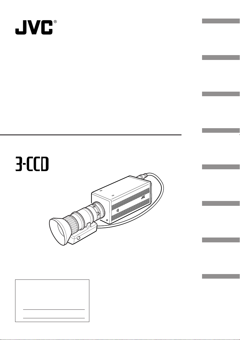
Digital Camera
Digitale Kamera
Caméra numérique
INSTRUCTIONS
KY-F70B
Illustration with optional lens attachment.
BEDIENUNGSANLEITUNG
MANUEL D’INSTRUCTIONS
C-MOUNT
DIGITAL
CAMERA
Settings and
adjustments
for recording
Basic operations
Various
recording
methods
KY-F70B
Menu screen
settings
Connecting
to a PC
For Customer Use:
Enter below the Serial No. which is
located on the unit. Retain this
information for future reference.
Model No. KY-F70B
Serial No.
Others
This instruction book is made from 100%
recycled paper.
SC96973-002
Page 2

IMPORTANT SAFEGUARDS
1. Read all of these instructions.
2. Save these instructions for later use.
3. All warnings on the product and in the operating instructions should be adhered to.
4. Unplug this appliance system from the wall outlet before cleaning. Do not use liquid
cleaners or aerosol cleaners. Use a damp cloth for cleaning.
5. Do not use attachments not recommended by the appliance manufacturer as they may
cause hazards.
6. Do not use this appliance near water - for example, near a bathtub, washbowl, kitchen
sink, or laundry tub, in a wet basement, or near a swimming pool, etc.
7. Do not place this appliance on an unstable cart, stand, or table. The
appliance may fall, causing serious injury to a child or adult, and
serious damage to the appliance.
Use only with a cart or stand recommended by the manufacturer, or
sold with the appliance. Wall or shelf mounting should follow the
manufacturer’s instructions, and should use a mounting kit approved
by the manufacturer. An appliance and cart combination should be
moved with care.
Quick stops, excessive force, and uneven surfaces may cause the
appliance and cart combination to overturn.
8. Slots and openings in the cabinet and the back or bottom are provided for ventilation,
and to insure reliable operation of the appliance and to protect it from overheating,
these openings must not be blocked or covered. The openings should never be blocked
by placing the appliance on a bed, sofa, rug, or other similar surface.
This appliance should never be placed near or over a radiator or heat register. This
appliance should not be placed in a built-in installation such as a bookcase unless
proper ventilation is provided.
9. This appliance should be operated only from the type of power source indicated on the
marking label. If you are not sure of the type of power supplied to your home, consult
your dealer or local power company. For appliance designed to operate from battery
power, refer to the operating instructions.
10. This appliance system is equipped with a 3-wire grounding type plug (a plug having a
third (grounding) pin). This plug will only fit into a grounding-type power outlet. This is a
safety feature. If you are unable to insert the plug into the outlet, contact your electrician
to replace your obsolete outlet. Do not defeat the safety purpose of the grounding plug.
11. For added protection for this product during a lightning storm, or when it is left unattended
and unused for long periods of time, unplug it from the wall outlet and disconnect the
antenna or cable system. This will prevent damage to the product due to lightning and
power-line surges.
12. Do not allow anything to rest on the power cord. Do not locate this appliance where the
cord will be abused by persons walking on it.
I
PORTABLE CART WARNING
(symbol provided by RET AC)
S3126A
Page 3

13. Follow all warnings and instructions marked on the appliance.
14. Do not overload wall outlets and extension cords as this can result in fire or electric
shock.
15. Never push objects of any kind into his appliance through cabinet slots as they mat
touch dangerous voltage points or short out parts that could result in a fire or electric
shock. Never spill liquid of any kind on the appliance.
16. Do not attempt to service this appliance yourself as opening or removing covers may
expose you to dangerous voltage or other hazards. Refer all servicing to qualified service
personnel.
17. Unplug his appliance from the wall outlet and refer servicing to qualified service personnel
under following conditions:
a. When the power cord or plug is damaged or frayed.
b. If liquid has been spilled into the appliance.
c. If the appliance has been exposed to rain or water.
d. If the appliance does not operate normally by following the operating instructions.
Adjust only those controls that are covered by the operating instructions as improper
adjustment of other controls may result in damage and will often require extensive
work by a qualified technician to restore the appliance to normal operation.
e. If the appliance has been dropped or the cabinet has been damaged.
f. When the appliance exhibits a distinct change in performance - this indicates a need
for service.
18. When replacement parts are required, be sure the service technician has used
replacement parts specified by the manufacturer that have the same characteristics as
the original part. Unauthorized substitutions may result in fire, electric shock, or other
hazards.
19. Upon completion of any service or repairs to this appliance, ask the service technician
to perform routine safety checks to determine that the appliance is in safe operating
condition.
(FOR USA AND CANADA) Note for Accessory options.
AA-P700MDU AC Adaptor is designed to use in Hospital or other
Medical usage.
AA-P700U AC Adaptor is designed to use for non Medical usage.
Please use for appropriate AC Adaptor for your system.
Mitsubishi printer CP-700DSU/E, CP-770DW, CP800DW are
not complying the UL-2601 safety standard on the date of this
booklet printed. The refer please read CAUTION for ACCESSORY
of the manufacture.
II
Page 4

JVC Sales Office
1. JVC PROFESSIONAL PRODUCTS (U.K.) LIMITED
ULLSWATER HOUSE, KENDAL AVENUE
LONDON, W3 0XA, UNITED KINGDOM
TEL : 020 8896 6000
2. JVC PROFESSIONAL PRODUCTS GMBH
GRÜENER WEG 12, 61169 FRIEDBERG / HESSEN GERMANY
TEL : (06031)6050
3. JVC PROFESSIONAL PRODUCTS ITALIA S.p.A.
VIA MARIO PANNUNZIO 4, 20156 MILANO, ITALY
TEL : (02)38.05.01
4. JVC FRANCE S.A.
1, AVENUE EIFFEL 78422 CARRIERES-SUR-SEINE, CEDEX FRANCE
TEL : 33.1.61.04.11.64.
5. JVC ESPAÑA S.A.
CTRA GRACIA MANRESA,KM 14 750 EDIFICIO CAN CASTANYER
08190 SANT CUGAT DEL VALLES (BARCELONA) SPAIN
TEL : (93)5653210
6. JVC BELGIUM S.A./N.V.
RUE DE LA PETITE LLE 3, KLEIN-EILANDSTRAAT,
BRUXELLES 1070 BRUSSEL, BELGIUM
TEL : (02)529-4211
7. JVC NEDERLAND B.V.
JVC PLEIN DE HEYDERWEG 2, 2314 XZ LEIDEN, NEDERLAND
TEL : (071)5453333
8. JVC SVENSKA AB
VEDDESTAVAGEN 15, S-175 62 JARFALLA-STOCKHOLM, SWEDEN
TEL : (08)7950400
9. JVC NORGE A/S
P.O.BOX 2012, POSTTERMINALEN 3103, TONSBERG, NORWAY
TEL : (333)61600
III
Page 5

10. JVC DENMARK A/S
HELGESHOJ ALLE 30 DK-2630, TASTRUP, DENMARK
TEL : (43)509000
11. SPITZER ELECTRONIC AG
MUHLEMATTSTRASSE 13, 4104 OBERWIL, SWITZERLAND
TEL : 0614051111
12. OY HEDPRO AB
LAUTTASAARENTIE 50, FIN-00200 HELSINKI, FINLAND
TEL : 35896828244
13. ELECTROINDUSTRIAL HELLAS S.A.
62, PIRAEUS AVE, 183 46 MOSCHATO, ATHENS, GREECE
TEL : (01)4832855
14. ORIELA S.A.
CAMPO STA. CLARA 160-A, 1100 LISBOA PORTUGAL
TEL : 351-1-882-3382
15. FACO HF
FAXAFEN 12, P.O.BOX 442, 108 108 REYKAJVIK, ICELAND
TEL : 91-588-3050
IV
Page 6
Thank you for purchasing the JVC KY-F70B
Digital Camera.
These instructions are for KY-F70BU.
SAFETY PRECAUTIONS
The instructions are given in three languages:
English from page E2 to E72
German from page G2 to G72
French from page F2 to F72
FOR USA AND CANADA
CAUTION
RISK OF ELECTRIC SHOCK
DO NOT OPEN
CAUTION: TO REDUCE THE RISK OF ELECTRIC SHOCK,
DO NOT REMOVE COVER (OR BACK).
NO USER SERVICEABLE PARTS INSIDE.
REFER SERVICING TO QUALIFIED SERVICE
PERSONNEL.
The lightning flash with arrowhead symbol,
within an equilateral triangle is intended to
alert the user to the presence of uninsulated “dangerous voltage” within the product’s
enclosure that may be of sufficient magnitude to constitute a risk of electric shock to
persons.
The exclamation point within an equilateral
triangle is intended to alert the user to the
presence of important operating and maintenance (servicing) instructions in the literature accompanying the appliance.
Information for USA
This device complies with Part 15 of the FCC Rules.
Changes or modifications not approved by JVC could
void the user’s authority to operate the equipment.
INFORMATION (FOR CANADA)
RENSEIGNEMENT (POUR CANADA)
• This Class B digital apparatus complies with Canadian
ICES-003.
• Cet appareil numérique de la classe B est conforme
à la norme NMB-003 du Canada.
Changes or modifications not approved by JVC could
void the user’s authority to operate the equipment.
WARNING:
TO REDUCE THE RISK OF FIRE OR ELECTRIC SHOCK, DO NOT EXPOSE THIS APPLIANCE TO RAIN OR MOISTURE.
This unit should be used with 12V DC only.
CAUTION:
To prevent electric shocks and fire hazards, do NOT
use any other power source.
CAUTION:
To prevent electric shock, do not open the cabinet. No
user serviceable parts inside. Refer servicing to qualified service personnel.
Due to design modifications, data given in this instruction book are subject to possible change without prior notice.
This unit is designed for professional use only.
WARNING ON LITHIUM BATTERY
The battery used in this device may present a
fire or chemical burn hazard if mistreated. Do not
recharge, disassemble, heat avobe 100°C or
incinerate.
Replace battery with Panasonic (Matsushita
Electric).
CR2025, use of another battery may present a
risk of fire or explosion.
• Dispose of used battery promptly.
• Keep away from children.
Do not disassemble and do not dispose of in fire.
•
E2
Page 7
For Sweden
VARNING
Explosionsfara vid felaktigt batteribyte.
Använd samma batterityp eller en ekvivalent typ
som rekommenderas av apparattillverkaren.
Kassera använt batteri enligt fabrikantens
instruktion.
For Denmark
ADVARSELI
Lithiumbatteri – Eksplosionsfare ved fejlagtig
håndtering.
Udskiftning må kun ske med batteri af samme
fabrikat og type.
Lever det brugte batteri tilbage til leverandøren.
For Norway
ADVARSEL
Lithiumbatteri – Eksplosjonsfare.
Ved utskifting benyttes kun batteri som anbefalt
av apparatfabrikanten.
Brukt batteri returneres apparatieverandøren.
For Finland
VAROITUS
Paristo voi räjähtää, jos se on virheellisesti
asennettu.
Vaihda paristo ainoastaan laltevalmistajan
suoaittelemaan tyyppiin. Hävitä käytetty paristo
valmistajan ohjeiden mukaisesti.
This equipment is in conformity with the provisions and protection requirements of the corresponding European Directives. This equipment is designed for professional video appliances
and can be used in the following environments.
• residential area (in houses) or rural area
• commercial and light industry; e.g. offices or theatres
• urban outdoors
In order to keep the best performance and furthermore for electromagnetic compatibility we
recommend to use cables not exceeding the following length:
Port Cable Length Port Cable Length
DC IN Exclusive Cable 2 meters MONITOR Monitor Cable 2 meters
LENS Cable of LENS 0.4 meter SCSI Cable for SCSI 3 meters
REMOTE Single wire 3 meters
Caution : Where there are strong electromagnetic waves or magnetism, for
example near a radio or TV transmitter, transformer, motor, etc., the
picture may be disturbed. In such case, please keep the apparatus away
from the sources of the disturbance.
KY-F70B is designed and operated for non patient equipment when used in the hospital or
other medical environments.
KY-F70B and AA-P700EG are tested and complied in accordance with IEC 601-1 safety
standards.
The use of accessory equipment not complying with the equivalent safety requirements of
this equipment may lead to reduce level of safety of the resulting system.
Consideration relating to the choice shall include:
Evidence that the safety certification of the accessory has been performed in accordance
to the appropriate IEC 601-1 and/or IEC 601-1-1 harmonized National Standards.
For inquiry, contact:
JVC PROFESSIONAL PRODUCTS (U.K.) LIMITED
ULLSWATER HOUSE, KENDAL AVENUE
LONDON, W3 0XA, UNITED KINGDOM
TEL : (0181)896-6000
E3
Page 8

Table of Contents
1. Introduction
Features ........................................................................................................................... 6
Accessories and attachments .......................................................................................... 6
Cautionary notes for the correct usage of this product .................................................... 7
Part names and their functions ........................................................................................8
Pin configurations of connectors ....................................................................................12
2. Before recording
Basic system 1 ...............................................................................................................14
Basic system 2 ...............................................................................................................15
Inserting the lithium battery ............................................................................................ 16
Mounting the lens ...........................................................................................................17
Connecting power .......................................................................................................... 18
Connecting a monitor .....................................................................................................19
®
Connecting an MO/Zip
Connecting a printer ....................................................................................................... 21
Mounting the camera ..................................................................................................... 22
Fall prevention ................................................................................................................ 23
3. Settings and adjustments for recording
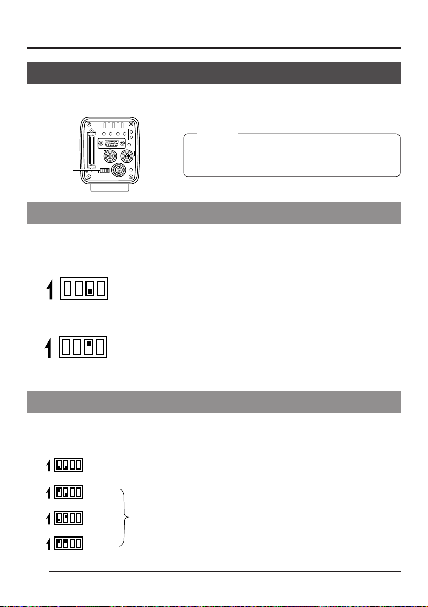
Setting the dip switches ................................................................................................. 24
Monitor output settings ...............................................................................................24
SCSI ID settings .........................................................................................................24
Menu settings .................................................................................................................25
VGA mode settings .................................................................................................... 25
Lens settings ..............................................................................................................25
Time and date settings ...................................................................................................26
Monitor adjustment ......................................................................................................... 28
Focus adjustment ...........................................................................................................29
White balance adjustment ..............................................................................................30
White shading adjustment ..............................................................................................32
White spot compensation ...............................................................................................34
drive .........................................................................................20
4. Basic operations
Recording images to the main unit memory .................................................................. 36
Playing back images from the memory ..........................................................................37
Returning to the REC mode .......................................................................................37
Saving images from the memory to an MO/Zip
E4
®
disk .................................................... 38
Page 9

Outputting images from the memory to a printer ........................................................... 39
Clearing images from the memory (PLAY/FREEZE menu screen)................................ 40
Clearing images from the memory (REC menu screen) ................................................ 41
5. Various recording methods
Recording a PC monitor .................................................................................................42
Outputting negative images ........................................................................................... 43
Synchronizing flash and FREEZE ..................................................................................44
6. Menu screen settings
Menu screen flow ...........................................................................................................46
Setting procedure ...........................................................................................................48
About the submenu screens of the REC MENU ............................................................ 50
EXPOSURE screen ....................................................................................................... 50
WHITE BALANCE screen ..............................................................................................53
FREEZE screen ............................................................................................................. 55
PROCESS (1/3) screen ................................................................................................. 55
PROCESS (2/3) screen ................................................................................................. 57
PROCESS (3/3) screen ................................................................................................. 58
SYSTEM SETTING screen ............................................................................................59
PLAY/FREEZE MENU screen........................................................................................ 61
REC MENU (QUICK) screen ......................................................................................... 62
Resetting settings (PLAY/FREEZE MENU screen)........................................................ 64
Resetting settings (REC MENU screen) ........................................................................ 65
7. Connecting to a PC
Capturing images using the provided software (KY-SCSI) .............................................66
Capturing images using commercially available software ..............................................67
Capturing images using the image capture board ......................................................... 68
8. Others
About ALC and EEI operations ......................................................................................70
Specifications .................................................................................................................71
Characters and symbols used in this instruction book
CAUTION Cautionary notes concerning operation of the unit
MEMO Reference such as restrictions of features, etc.
Reference page or item
E5
Page 10
1. Introduction
Features
● This digital camera uses three 1.45 million pixel 1/2 inch 3-CCD.
● Newly developed 1/2 inch C mount Dichroic prism for the colour separation prism.
● The semi-animation of 1360 × 1024 pixels can be output with analog signal (7.5 frames/sec-
ond) and the still picture of 1360 × 1024 pixels can be captured.
● Image capturing capability using a capture board since video signals are processed in realtime by the built-in DSP and outputted as RGB analog signals of 7.5 frames/sec.
● Monitor output can be scan-converted to 640 × 480 pixels for output to a VGA monitor.
● Using the provided special application software [KY-SCSI] allows connection of a personal
computer via SCSI connection for remote control, display of preview image and capture of still
images.
● Output digital still images to an MO drive, Zip
tion.
● Remotely control your PC using RS-232C connection. (software not included)
Accessories and attachments
®
drive or compatible printer using SCSI connec-
0
2
2
R
5
C
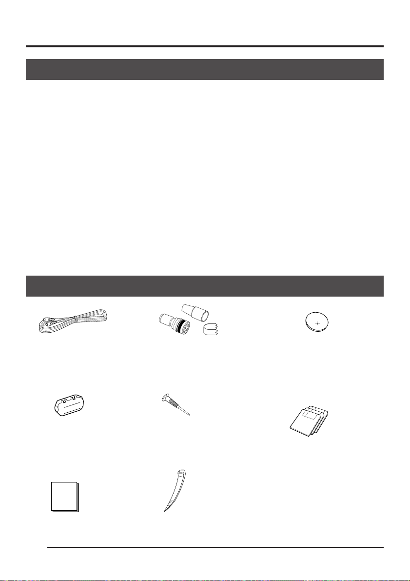
Power cable (2 m)
For connecting with AC
adapter 8-pin cable
( page 18)
Clamp filter
For power cable
( page 18)
Instruction book
E6
Remote plug (10-pin)
REMOTE terminal plug
( page 12)
Mini screwdriver
For replacing battery
( page 16)
Wire clamp (5 units)
For clamping rear cables, etc.
Battery (CR2025)
For time and date backup
( page 16)
Replace the battery once two
year.
Floppy disk (3 disks)
Special application software
[KY-SCSI] and TWAIN driver
For details, see the “Readme.txt”
file of the software
( page 66)
Page 11

Cautionary notes for the correct usage of this product
• Before recording an important event, etc., always check to make sure that this product is
working properly.
• We are not liable for any missed recordings caused by malfunction of this unit, etc.
Phenomena unique to CCD
• Smearing and blooming
When using CCD to record a bright light source, a smearing effect may occur running a
white line vertical to the light source. In addition, a blooming effect may also occur when the
light source is extremely bright, spreading light to the source surroundings.
• Line distortion
Line and patterns may appear distorted when recorded.
• White spots
White spots may appear on the screen when operating under high temperatures. Always
use the product under recommended ambient temperatures.
White spots may also appear at a slow shutter speed setting (1/8 s or higher).
To reduce this phenomenon, this product is provided with at built-in white spot compensation function. ( page 34)
Cautionary notes
• Influence of strong electric waves and magnets
Screen noise and discolouration may occur when using the product near antennas of radios and televisions or near transformers, monitors, etc. with strong magnetic force.
• Compatible lenses ( page 17 Mounting the lens)
Although the lens mount of this product is a type C mount, take caution as there are restrictions on the lenses that can be used.
This product is not equipped with a back-focus adjustment feature. Please use a lens
equipped with the back-focus adjustment feature.
• To save electricity, turn off the system when not in use.
Cleaning
When clean the equipment please use dry cleaning cloth or wet cleaning cloth with small
amount of alcohol.
Do not spill any liquid into KY-F70B.
E7
Page 12
1. Introduction (continued)
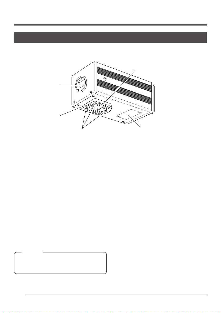
Part names and their functions
[Front and bottom]
C-MOUNT
CAMERADIGITAL
KY
-F70B
쐃 Lens mount
Although the lens mount conforms to the
type C mount lens, there are restrictions
on the lenses that can be used.
Mounting the lens ( page 17)
쐇 Camera mounting bracket
Although the mounting bracket is mounted
on the bottom of the camera when shipped,
the bracket can also be mounted on the
top of the camera.
Mounting the camera ( page 22)
쐋 Locking screws for the camera
mounting bracket
(M2.6 × 6mm, 3 units)
CAUTION
Always use the attached screws. Using screws
that exceed 6mm may result in malfunction of
the unit.
쐏 Screw holes for mounting the
camera (1/4-inch)
Used when mounting the camera to a fixer
or rotating platform.
쐄 Lithium battery compartment
Used to compartment the lithium battery
for time and date backup. The lithium battery is not installed when shipped.
Please install the attached lithium battery
(CR2025) before use.
Inserting the lithium battery ( page 16)
E8
Page 13
[Rear]
SCSI
UPMENU
MONITOR
REMOTE
ON 1 2 3 4
SEE INSTRUCTION MANUAL
AW/SELSEND
DC IN
MODE
SETDOWN
REC
PLAY
FREEZE
LENS
POWER
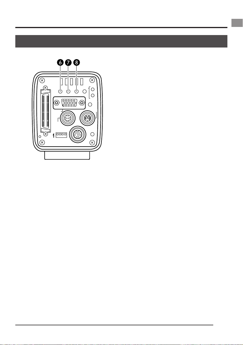
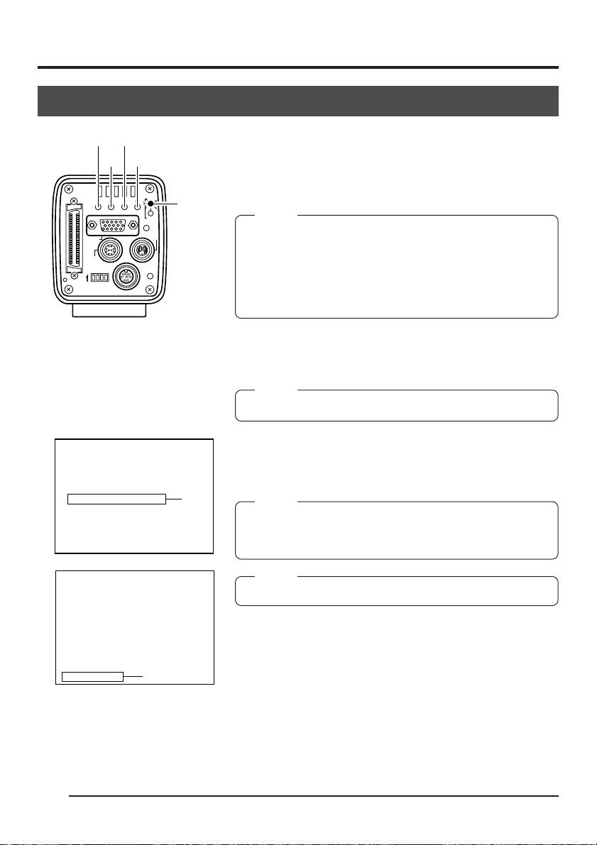
쐂 MENU button
Press this button to output the menu screen
from the MONITOR terminal.
Press the button once more to clear the
menu screen.
Setting in the menu screen ( page 46)
쐆 SEND/UP button
● Press this button to output the same still
image* that is being outputted to the
MONITOR terminal to an MO/Zip
or printer.
Save images in memory to an MO/Zip
( page 38)
Output images in memory to a printer
( page 39)
* A still image refers to an image recorded
by pressing the FREEZE button while in
the REC mode or an image being played
back in the PLAY mode.
®
drive
®
disk
● While the menu screen is being displayed, press this button selected item
up.
While an item is selected, use this button to change the set value.
Menu screen flow ( page 46)
쐊 AW/SEL/DOWN button
● [AW (Auto White)]
Press this button to adjust the white balance when the light source of the subject is changed.
White balance adjustment ( page 30)
● [SEL (Select)]
Pressing this button each time while in
the PLAY mode will switch to the previous image in memory.
* The PLAY mode refers to the condition
which the unit is playing back recorded
images from the memory.
Playing back images from memory
( page 37)
● [DOWN]
While the menu screen is being displayed, press this button selected item
down.
While an item is selected, use this button to change the set value.
Menu screen flow ( page 46)
E9
Page 14
1. Introduction (continued)
Part names and their functions (continued)
[Rear (continued)]
Ventilation hole
SCSI
SEE INSTRUCTION MANUAL
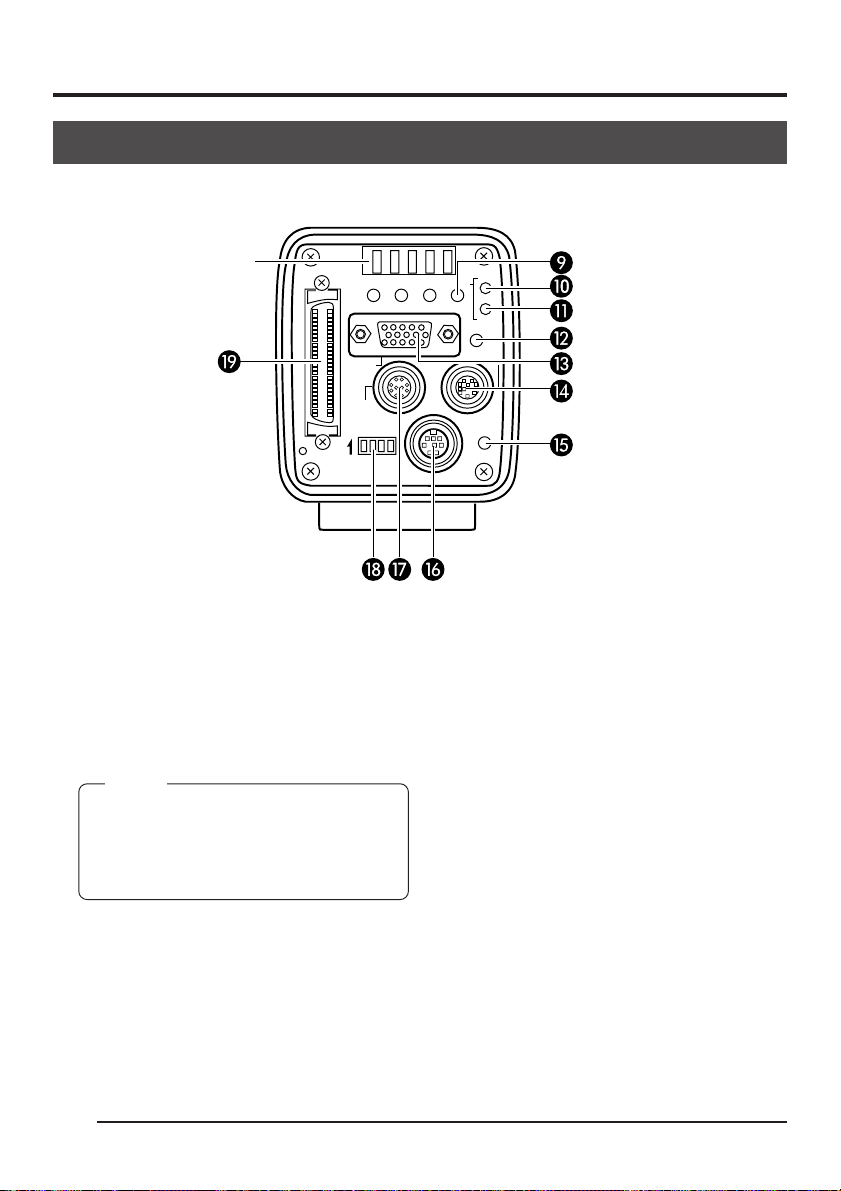
쐎 MODE/SET button
● [MODE]
Pressing this button each time will switch
between the REC (record)* and PLAY
(playback) modes.
* REC mode is the condition which the unit
has either captured an image or is ready
to write an image to the main unit memory.
MEMO
The default mode when the power is turned
on is REC.
If this button is pressed in the condition in
which there is no playback image stored in
the memory, “NO PICTURE” is displayed.
Recording images to the main unit memory
( page 36)
Playing back images from the memory
( page 37)
● [SET]
While the menu screen is being displayed,
use this button to select a submenu or
confirm a selected item or set value.
Setting in the menu screen ( page 46)
E10
MONITOR
REMOTE
ON 1 2 3 4
REC
MODE
AW/SELSEND
UPMENU
SETDOWN
PLAY
FREEZE
LENS
DC IN
POWER
쐅 REC display lamp
This lamp lights when in the REC* mode.
During FREEZE, this display lamp will flash.
* During the REC mode, camera images
are outputted to the MONITOR terminal.
Pressing the FREEZE button at this time
will save the image to the main unit
memory.
Recording images to the main unit memory
( page 36)
쐈 PLAY display lamp
This lamp lights when in the PLAY* mode.
* During the PLAY mode, images saved in
the main unit memory are played back
by outputting to the MONITOR terminal.
Playing back images from the memory
( page 37)
Page 15

쐉 FREEZE button
While in the REC mode, press this button
to capture a still image (freeze) of the images being outputted through the MONITOR terminal. At the same time, the still
image is saved to the main unit memory.
Pressing this button once more will cancel
the still image and return to the camera
images.
Saving images to the main unit memory
( page 36)
MEMO
You can also set the unit to automatically cancel the still image.
FREEZE screen, CANCEL item ( page 55)
씈 MONITOR output terminal
(D-sub 15-pin, female)
Used to connect to a VGA monitor or SXGA
compatible capture board.
The default setting is set to VGA monitor
compatible. To change the setting from VGA
mode to SXGA mode, change the dip
switch settings.
Pin configuration of connectors ( page
13)
Setting the monitor ( page 24)
● When in the SXGA mode, images of
1360 × 1024 pixles (7.5 frames/sec.) are
outputted.
● For the VGA mode, you can select between the FINE mode of 640 × 480 pixels (7.5 frames/sec.) or DRAFT mode of
640 × 240 pixels (30 frames/sec.) in the
menu screen.
Setting the VGA mode ( page 25)
씉 LENS connection terminal
Used to connect the lens cable.
Pin configuration of connectors ( page
12)
Mounting the lens ( page 17)
씊 POWER display lamp
This lamp lights when the power of the main
unit is on.
씋 DC IN power input terminal
(Mini DIN 8-pin, female)
Main unit power supply (DC 12V) is supplied through this terminal.
For the power supply, use the AA-P700 AC
adapter.
Pin configuration of connectors ( page
12)
Connecting power ( page 18)
씌 REMOTE terminal
(Metal 10-pin, female)
Used to connect external devices such as
a freeze switch or flash unit.
Pin configuration of connectors ( page
12)
Basic system 2 ( page 15)
5. Various recording methods ( page 44)
씍 Dip switches
Used to set the SCSI ID, monitor and output colour bar.
SCSI ID setting ( page 24)
Monitor output setting ( page 24)
Monitor adjustment ( page 28)
씎 SCSI terminal
(Half-pitch 50-pin, female)
Used to directly output to an MO drive or
printer.
The default setting of the SCSI ID is 7.
Change the SCSI ID setting when connecting to a PC, etc. (SCSI-2)
Pin configuration of connectors ( page
13)
Connecting an MO/Zip
Connecting a printer ( page 21)
SCSI ID Setting ( page 24)
Connecting to a PC ( page 66)
®
drive ( page 20)
E11
Page 16

1. Introduction (continued)
KY-F70B
C Mos IC
Pin configurations of connectors
Power terminal (Mini DIN 8-pin, female)
7
8
5
2
6
3
4
1
Pin no. Signal name
1NC
2 GND
3NC
4NC
5 GND
6 12V
7NC
8 12V
Lens terminal (Metal 12-pin, female)
10
9
8
7
6
12
Pin no. Signal name
1NC
2 FREEZE
3 GND
4NC
5 IRIS CONTROL
6 12V DC
7 IRIS POSITION
8 IRIS AUTO /MANU
9 to 12 NC
1
2
3
4
11
5
Remote terminal (Metal 10-pin, female)
FREEZE
WEN
FLASH
* However, insert a diode as shown in the dia-
8
7
10
6
5
1
2
9
3
4
Pin no. Signal name
1 A. WHITE L active Zi=22k Ω
2 FREEZE L active Zi=100k Ω
3
WEN L active Zo=22 Ω 3.3V(p-p)
4 FLASH
5 SEND
6 RS-SDI
7 RS-SDO
8 GND
9 12V
10 OPERATION
CAUTION
• Consult your JVC dealer concerning the remote terminal connection.
• Remote cable must use shielded cable.
Outer shield of remote cable must to connect
10-pin connector outer metal shell.
Terminal
name
I/O
IN
• 5V CMOS
• Schmidt Trigger
• Pull-up to 5V at
100k Ω
OUT
• 3.3V (p-p)
negative polarity
OUT
• Open collector
Conditions
• Contact point
recommended
• Maximum rated
voltage: 5.3V
• H level: 3.5 ~ 5.0V
• L level: 0 ~ 0.8V
• CMOS (5V): OK*
• TLL not possible
• Pulse width:
130 µs or higher
• Output only when
in the SXGA mode
• Maximum rated
current: 150mA
• Maximum rated
voltage: 12V
gram below.
E12
Page 17
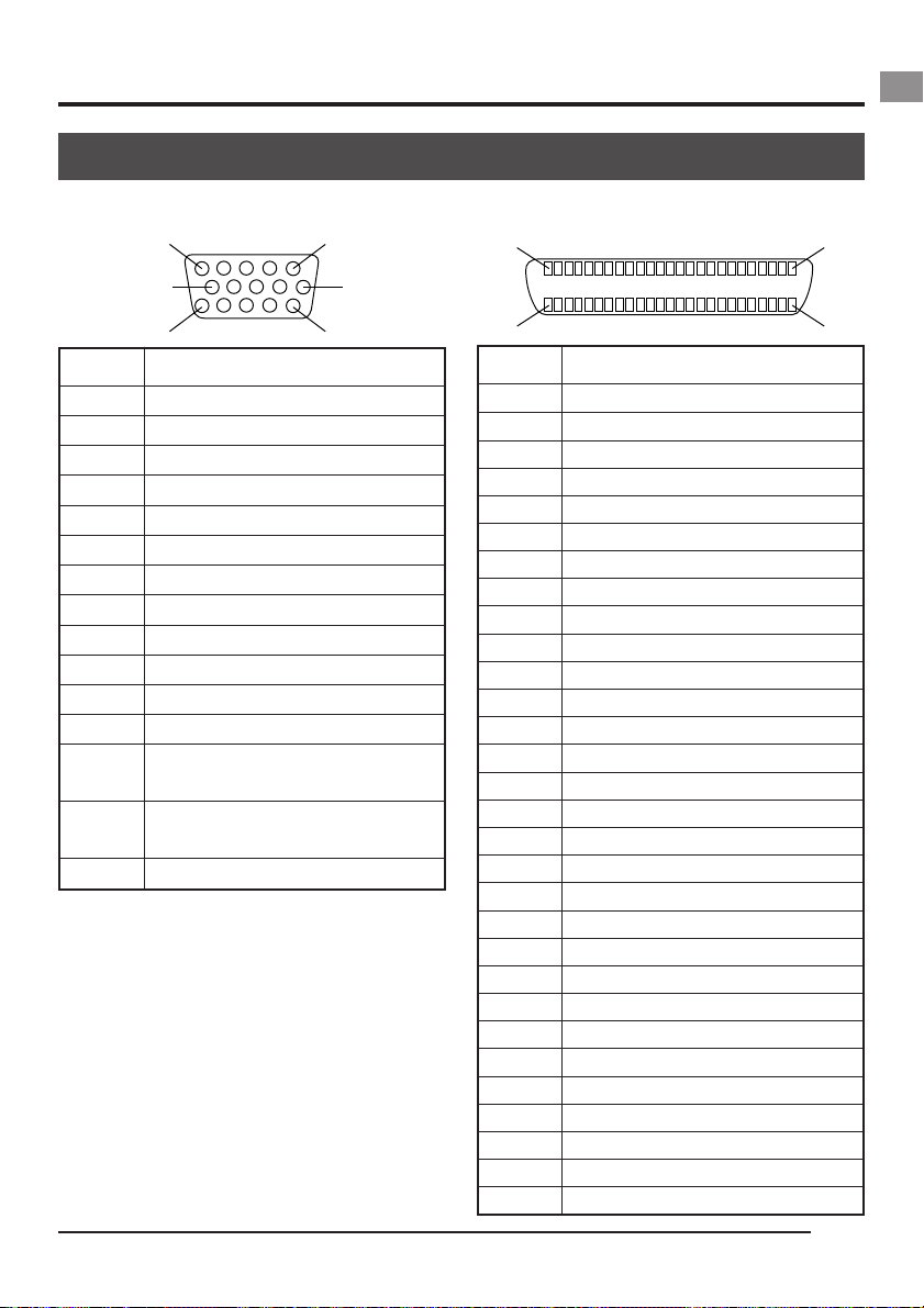
Monitor terminal (D-sub 15-pin, female)
15
SCSI terminal (Half-pitch 50-pin, female)
25
1
10
15
6
11
Pin no. Signal name
1 R OUT 700mV
2 G OUT 700mV
3 B OUT 700mV
(p-p)
(p-p)
(p-p)
, 75 Ω
, 75 Ω
, 75 Ω
4NC
5NC
6 R GND
7 G GND
8 B GND
9NC
10 GND
11 GND
12 NC
13 Hs (3.3V(p-p) negative polarity
Zo=22 Ω)
14 Vs (3.3V(p-p) negative polarity
Zo=22 Ω)
15 NC
2650
Pin no. Signal name
1 ~ 11 GND
12 GND
13 NC
14 GND
15 ~ 25 GND
26 DB 0
27 DB 1
28 DB 2
29 DB 3
30 DB 4
31 DB 5
32 DB 6
33 DB 7
34 DBP
35 GND
36 GND
37 GND
38 TERMPWR; (input only)
39 GND
40 GND
41 ATN
42 GND
43 BSY
44 ACK
45 RST
46 MSG
47 SEL
48 CD
49 REQ
50 I/O
E13
Page 18
2. Before recording
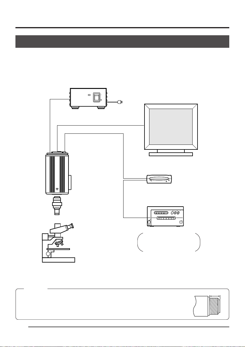
Basic system 1
While checking the images from the camera on the monitor, output the images to an MO disk,
®
Zip
disk or printer.
Connect to the
power supply
( page 18)
MONITOR VIDEO IN
DC IN
KY-F70B
CAMERADIGITAL
C-MOUNT
AC adapter
SCSI
Microscope
adapter
AA-P700
POWER
ON
OFF
AC ADAPTER AA-P700
AC
Connect the PC monitor (VGA)
( page 19)
VGA monitor
Connect the MO/Zip
MO drive
®
or Zip
ALARM SHEET
POWER
drive
PAPER
drive ( page 20)
CP700DSA
MITSUBISHI
ONLINECOPY
& CUTPAPER FEED
DATA
OPEN
Connect the printer
( page 21)
Compatible Printer
(Mitsubishi CP-700DSU/E)
CP-770DW
CP-800DW
®
• Be sure to terminate the last device on the SCSI bus.
• For the power supply, always use the AA-P700 AC adapter.
CAUTION
Use a 1/2 inch C mount microscope adapter compatible to the used microscope.
To avoid damage to the unit, always use an adapter that is 4mm or less from
the lens mount side.
E14
4mm or less
Adapter
Page 19
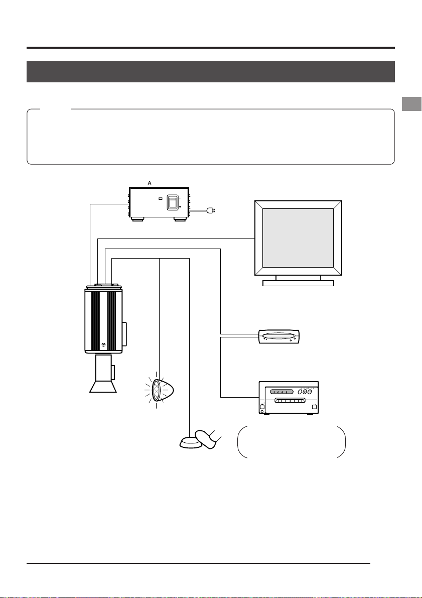
Basic system 2
This is a system to record with this camera using a flash timed by an external freeze switch.
MEMO
Use the following setting for flash connection:
IRIS MODE: MANUAL ( page 50)
WHITE BAL: MANUAL ( page 53)
ABL: Set in MASTER BLACK ( page 56, 57)
AA-P700
AC ADAPTER AA-P700
POWER
ON
OFF
AC100V
DC IN
Mount the lens
( page 17)
MONITOR
SCSI
REMOTE
KY-F70B
CAMERADIGITAL
C-MOUNT
AC adapter
Flash
Freeze switch
VGA monitor
MO drive unit
CP700DSA
MITSUBISHI
ONLINECOPY
& CUTPAPER FEED
PAPER
ALARM SHEET
DATA
POWER
OPEN
Compatible Printer
(Mitsubishi CP-700DSU/E)
CP-770DW
CP-800DW
• Be sure to terminate the last device on the SCSI bus.
E15
Page 20
2. Before recording (continued)
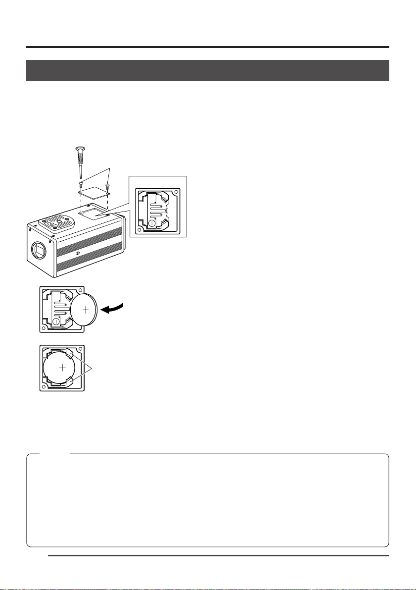
Inserting the lithium battery
The lithium battery is used to back up the time and date data.
Install the lithium battery (CR2025) before using the unit.
Replace the battery once two year.
If the BATTERY EMPTY message appears when turning on the power, replace the battery with
a fresh lithium battery.
<
Install
1.
2.
>
Mini screwdriver (attached)
Screws
DIG
ITAL
CAMERA
KY-F70B
C
-M
O
U
N
T
5
2
0
2
R
C
Battery compartment
Remove the screws (2 units) using the attached mini screwdriver, then open the cover.
Completely insert the lithium battery in the direction of the arrow with the + side facing up.
3.
5
2
0
2
R
C
4.
Replace the cover and retighten the screws.
Holders
Make sure that the battery is securely in position by the holders as shown in the diagram.
(To remove the battery, follow the procedure in reverse.)
MEMO
• The time and date will not be displayed correctly when the battery is not installed. When replacing the
lithium battery, reset the time and date.
Setting the time and date ( page 26)
• A BATTERY EMPTY message will appear immediately after replacing the battery and turning on the
power. This is not a malfunction. If the message continuously appears after turning on the power the
second time, consult your JVC dealer.
• The BATTERY EMPTY message will not appear when turning on the power immediately after turning
off the unit. Wait at least 20 seconds before turning the power back on.
E16
Page 21
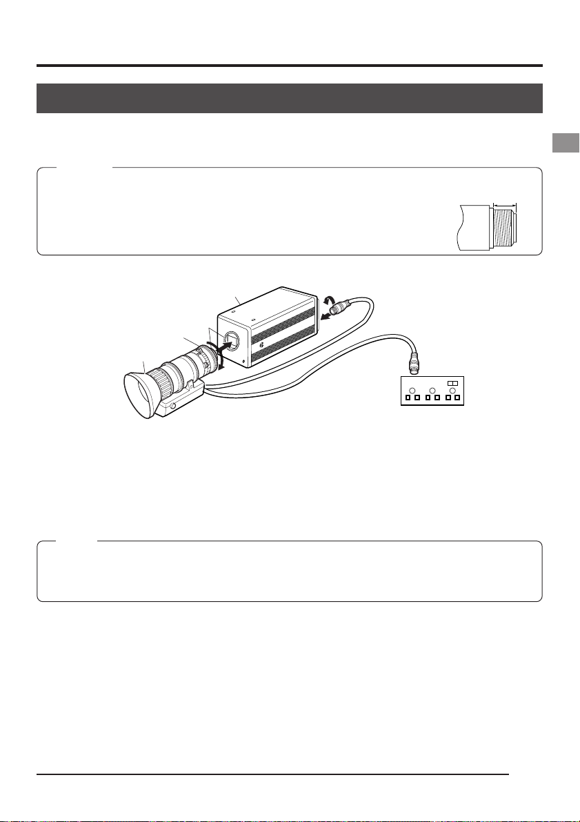
Mounting the lens
Follow the procedure shown below when mounting an auto-iris lens. For further details, see the
instruction manual of the lens and lens remote control.
CAUTION
• Perform mounting of the lens with the power of the camera turned OFF. Mounting with the power on
could result in damage.
• Lens is not included with this unit.
To avoid damaging the main unit, make sure that the lens mount of the lens to be
used is 4mm or less.
3.
Camera head
Lock
Male
4mm or less
Lens
Thread section
Mount clamp ring
Lens
Compatible
zoom lens
FUJINON
S14×7.3DA-D24
1.
Remove the lens mount cap. At this time, take caution so that dust do not enter inside the
C-MOUNT
2.
B
0
7
-F
Y
K
CAMERA
DIGITAL
4.
Lock
Female
Lens remote control
Compatible lens remote control
FJINON, RMD-10, RMD-20
mount.
2.
To mount the lens, lightly press the thread section of the lens mount onto the thread section
of the main unit, then turn the mount clamp ring slowly clockwise until it is securely tightened.
MEMO
To change the position of the lens rotation:
햲 First, turn the mount clamp ring counterclockwise (1/4 turns) with the lens facing you.
햳 Slowly turn the lens and after adjusting the position, retighten the mount clamp ring.
3.
Insert the camera cable of the lens into the lens connection terminal on the rear of the main
unit, then securely lock.
The iris control is made automatically from the camera.
When using a manual iris lens, set the IRIS MODE to MANUAL ( page 50).
4.
When using the lens remote control, connect the lens control cable (female) to the remote
control.
When operating the lens iris manually by lens remote control connection, set IRIS MODE to
manual. ( page 50)
E17
Page 22
2. Before recording (continued)
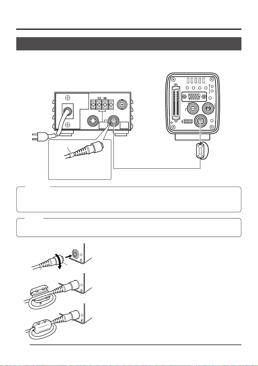
Connecting power
Between the 8 pin DC IN terminal on the rear of the main unit and the 8 pin TO CAMERA
terminal of the AC adapter (AA-P700) connect the power cable (2m) which is provided.
AA-P700
DC 12V=OUTPUT
EITHER
OUTPUT
MAX 1.25A
TO CAMERAS(Y/C) OUTPUT
VIDEO OUTPUT
SEE INSTRUCTION
MANUAL
SCSI
MONITOR
REMOTE
ON 1 2 3 4
SEE INSTRUCTION MANUAL
REC
MODE
AW/SELSEND
UPMENU
SETDOWN
PLAY
FREEZE
LENS
DC IN
POWER
AC adapter
AC
White marking
Provided
Clamp filter
Connect the end with the
Provided power cable
white marking to the AC
adapter.
CAUTION
• Be sure to use the AA-P700 power supply.
• Before connecting power cable, make sure that the power switch on the AA-P700 is set to OFF.
Connecting with the power switch on may result in camera malfunction.
MEMO
• Wait at least 10 seconds before turning the power switch back on, when it has just been turned off.
• Turning the power switch on and off quickly may cause malfunctions, such as failure to boot, etc.
Figure 1
DC IN
PO
W
ER
After inserting the plug completely, tighten the secur-
ing ring. (Figure 1)
Make sure white indication of power cable comes to
AA-P700 side.
To minimise emission of unwanted electrical waves,
Figure 2
Plug
Ring
D
C
IN
PO
W
ER
mount certainly the provided clamp filter as shown in
D
C
IN
PO
W
ER
Figure 2 and 3 on the left.
Wind the power cable once around the clamp filter.
Figure 3
Ensure that the clamp filter is mounted as close to
the camera as possible as shown in the diagram.
E18
Page 23
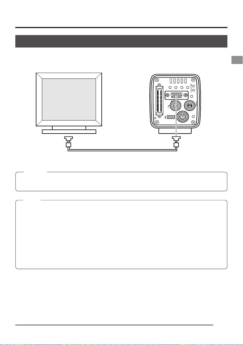
Connecting a monitor
Connect the PC monitor (VGA) to the MONITOR terminal on the rear of the main unit.
SCSI
MONITOR
REMOTE
ON 1 2 3 4
SEE INSTRUCTION MANUAL
REC
MODE
AW/SELSEND
UPMENU
SETDOWN
PLAY
FREEZE
LENS
DC IN
POWER
MONITOR terminal
CAUTION
• Before connecting, make sure that the power of all systems are turned off. Connecting with the power
turned on may result in malfunction.
MEMO
• The monitor cable must use clump filter for both ends to minimize emission of unwanted electrical
waves. (Commercially available VGA video cable is recommended)
• For the pin assignment, see page 13 Pin configuration of connectors
• Monitor conditions:
fH: 31.47 kHz
fV: 59.94 Hz
Sync signal: H/V separate, TTL negative polarity
• Dip switch setting ( page 24)
VGA mode (set dip switch No. 3 to OFF)
Do not connect the unit to a VGA monitor directly when in the SXGA mode (dip switch No. 3 ON)
E19
Page 24

2. Before recording (continued)
Connecting an MO/Zip® drive
It is possible to output image data stored in the main unit memory to an MO drive or a Zip® drive.
( Page 38 Saving images from the memory to an MO/Zip
CAUTION
Before connecting, make sure that the power of all systems are turned off. Connecting with the power turned on
may result in malfunction.
®
The MO/Zip
drive must be equipped with a terminator
power supply.
®
Recommended Zip
iomega Zip
®
connection)
drive:
250 (for SCSI
®
disk)
Dip switches
SCSI
MONITOR
REMOTE
ON 1 2 3 4
SEE INSTRUCTION MANUAL
SCSI terminal
REC
MODE
AW/SELSEND
SETDOWN
UPMENU
PLAY
FREEZE
LENS
DC IN
POWER
• Be sure to terminate the last device on the SCSI bus.
To directly connect the MO drive to the main unit, set the dip switches on the rear of the main unit
as shown below.
ON 1 2 3 4
(ID : 7)
CAUTION
Set the ID of the MO drive side to other than 7.
MEMO
®
• Turn on the camera power after turning on the MO/Zip
era power when turning the MO/Zip
®
drive power off.
drive power. Furthermore, reinsert the cam-
• Use a formatted DOS/V disk.
®
• Connecting two or more MO/Zip
Neither is it possible to connect an MO drive and a Zip
• The image data outputted to an MO/Zip
drives at the same time is not possible.
®
drive unit will be 1360 × 1024 pixels, regardless whether the
®
drive at the same time.
mode is VGA or SXGA, or whether the VGA mode is set to FINE or DRAFT.
• The maximum allowed length of the SCSI cable is 3m.
• It is not possible to simultaneously output the image data to a printer and MO/Zip
• The image data will be save as uncompressed TIF files (one file approx. 4 megabytes).
E20
®
drive.
Page 25
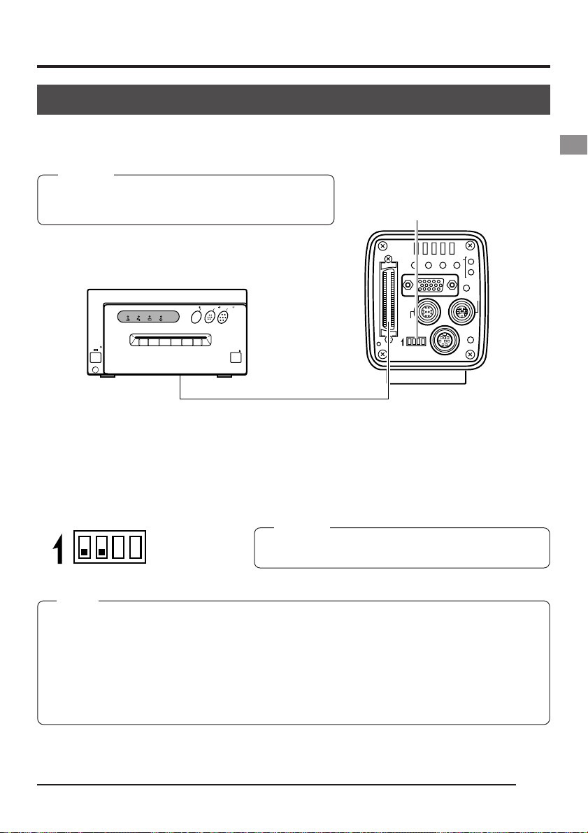
Connecting a printer
It is possible to directly output image data stored in the main unit memory to a printer.
( page 39 Outputting images from the memory to a printer)
CAUTION
Before connecting, make sure that the power of all systems are turned off. Connecting with the power turned on
may result in malfunction.
Dip switches
Use the following printer.
Mitsubishi: CP-700DSU/E, CP-770DW, CP-800DW
CP700DSA
MITSUBISHI
]
ONLINECOPY
PAPER
ALARM SHEET
DATA
POWER
& CUTPAPER FEED
OPEN
SCSI
MONITOR
REMOTE
ON 1 2 3 4
SEE INSTRUCTION MANUAL
REC
MODE
AW/SELSEND
SETDOWN
UPMENU
PLAY
FREEZE
LENS
DC IN
POWER
SCSI terminal
• Be sure to terminate the last device on the SCSI bus.
When directly connecting the main unit to a printer, set the dip switches on the rear of the main
unit as shown below.
ON 1 2 3 4
(ID : 7)
MEMO
• Turn on the camera power after turning on the printer power.
• Connecting two or more printers at the same time is not possible.
• The image data outputted to a printer will be 1312 × 1024 pixels, regardless whether the mode is
VGA or SXGA, or whether the VGA mode is set to FINE or DRAFT.
• The maximum allowed length of the SCSI cable is 3m.
• When connecting an MO/Zip
• It is not possible to simultaneously output the image data to a printer and MO/Zip
®
drive to a PC, separate setting of the SCSI ID is required.
CAUTION
Set the ID of the printer side to other than 7.
®
drive.
E21
Page 26
2. Before recording (continued)
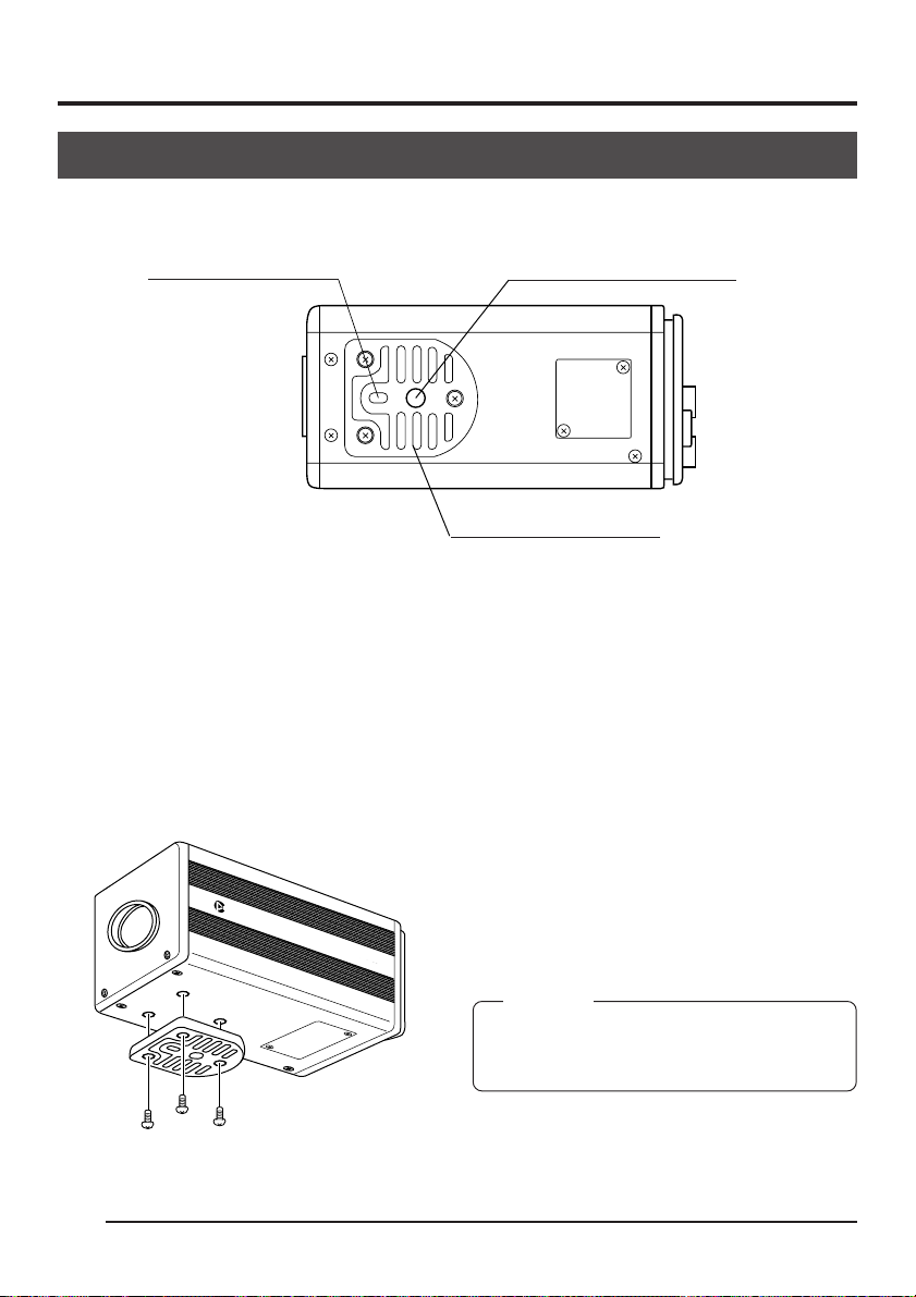
Mounting the camera
<
Mounting method
Rotation prevention hole
>
Camera mounting screw hole
Camera mounting bracket
● When mounting the camera, use the camera mount screw hole located on the camera mounting bracket.
● When mounting the camera, use the rotation prevention hole to prevent the unit from falling
and securely mount the unit.
<
Changing the camera mounting bracket position
>
E22
C-MOUNT
DIGITAL
When shipped, the camera mounting bracket
is mounted on the bottom of the unit. To mount
it on the top of the unit, simply remove the 3
locking screws holding the camera mounting
CAM
ERA
KY-F70B
bracket.
CAUTION
Always use the attached screws. Using screws
that exceed 6mm may result in malfunction of
the unit.
Page 27

Fall prevention
Fall prevention
wire chain
6mm
Camera head
KY-F70B
CAMERADIGITAL
C-MOUNT
MEMO
• Special attention is required when mounting the unit to the wall or ceiling. Rather
than attempting to do it yourself, request a qualified person to perform such installation. Falling of the unit may result in bodily injury.
• To prevent the unit from falling, connect the unit to a strong surface with a wire
chain, etc. When connecting such chain, use the bracket locking screw hole on the
side which the camera mounting bracket is not mounted. (M2.6 × 6mm)
Take special caution to the length of the optional wire as well.
• For the fall-preventive wire, use the one with the strength that is more than 10 times
of a mass including the lens.
E23
Page 28
3. Settings and adjustments for recording
Setting the dip switches
The type of PC monitor to use and the ID during SCSI connection are set using the dip switches.
Dip switches
SCSI
MONITOR
REMOTE
ON 1 2 3 4
SEE INSTRUCTION MANUAL
REC
MODE
AW/SELSEND
SETDOWN
UPMENU
PLAY
FREEZE
LENS
DC IN
POWER
CAUTION
Turn the power off before setting the dip switches. Setting
the switches with the power on will not change the settings.
Monitor output settings
Dip switch no. 3 is set depending on whether using a system which uses a commercially available VGA monitor or a system which uses a capture board. <Default setting: OFF
ON 1 2 3 4
VGA output setting
>
Set when directly connecting a VGA monitor to the MONITOR terminal on the rear of the main unit.
Set to OFF
SXGA output setting
ON 1 2 3 4
Set for systems using a capture board.
The signal from the MONITOR terminal on the rear of the main unit
is inputted through the analog input compatible video capture board.
Set to ON
( Page 68 Capturing images using the image capture board)
SCSI ID settings
DiP switches 1 and 2 are set depending on the used system to set the SCSI ID. <Default ID: 7
ON 1 2 3 4
ON 1 2 3 4
ID=7
ID=6
Set when connecting a printer or MO drive unit directly to the main
unit. When making this setting, the main unit will become the initiator.
Set when exporting images to a PC.
ON 1 2 3 4
ID=5
ON 1 2 3 4
ID=4
Make sure that the ID numbers of the connecting devices are not
the same.
When making this setting, the PC will become the initiator and the
main unit will become the target.
( Page 66 Connecting to a PC)
E24
>
Page 29

Menu settings
The settings for the VGA mode and lens are made on the menu screen.
The menu screen is outputted through the VGA monitor.
VGA mode settings
Set to output either semi-animation (7.5 frame/sec.) of 640 × 480 pixels or full-motion video (30
frames/sec.) of 640 × 240 pixels to the VGA monitor.
--- ETTING ---SYSTEM S
ON SCREEN
FRZ D I SPL AY
ITY
PR IOR
MON I T
OR
AREA
BAR LEVEL
NEGA
SYNC ON G
MENU RE
S
ET
VIDEO ME
MOR
ITMEADJUST
MEMORY NUM
::O
N
:
DISK
:FINE
:NARROW
:0.7V
:OFF
:OFF
..
Y
..
RCLEA ..
Set MONITOR in the SYSTEM SETTING screen.
( Page 59)
FINE: Semi-animation (update rate 7.5 frames/sec.) of
640 × 480 pixels
DRAFT: Full-motion video (update rate 30 frames/sec. of
640 × 240 pixels
(Default setting: FINE)
MEMO
• This menu item will be displayed with ------------ when set to the SXGA mode by the rear dip switches,
disabling changes.
• Setting the shutter speed slower than the time interval (update rate) for screen output will slow the
update rate according to the shutter speed.
Lens settings
Set according to whether the used lens to be used is an auto-iris lens or a manual lens.
--- ---EXPOSURE
IRIS MODE : AU
AE LEVEL
IRIS LEVEL
IRIS DETECT
I RI S AREA
SHUTT ER
SPEED
LEVEL
ITY
SENS I T I V
ALC MAX
:0
:---:NORM1AL
:FULL
:STEP
:1/8s
:ISO
TO
P:STE
00
400:ISO
Set the IRIS MODE on the EXPOSURE screen.
( Page 50)
AUTO: Set when using an auto-iris lens
MANUAL: Set when using a manual lens, using an autoiris lens in MANUAL or no lens.
(Default setting: AUTO)
E25
Page 30
3. Settings and adjustments for recording (continued)
Time and date settings
DOWN
MENU
UP
SCSI
UPMENU
MONITOR
REMOTE
ON 1 2 3 4
SEE INSTRUCTION MANUAL
MODE/SET
REC
MODE
AW/SELSEND
SETDOWN
PLAY
FREEZE
LENS
DC IN
POWER
REC lamp
1.
Press the MODE button to enter the REC mode (REC
lamp on), then press and hold the MENU button for at
least 2 seconds to display the REC MENU screen.
( page 10 MODE button)
MEMO
• When the power is turned on, the mode will be the REC
mode.
• If the button is pressed for less than 2 seconds, the REC
MENU (QUICK) screen will appear. ( Page 49)
• To switch from the PLAY mode to the REC mode, press the
MODE button to light up the REC lamp.
2.
Press the UP or DOWN button to select 5. SYSTEM
SETTING, then press the SET button. The SYSTEM
SETTING screen will appear.
MEMO
When selected, item display will become purple.
1 :EXPOSURE
2 :WHI TE BA LANCE . .
3:FREEZE..
4 : P ROCES S . .
5 :SYS TEM SETT ING . .
REC MENU screen
--- ETTING ---SYSTEM S
ON SCRE EN
FRZ D I SPLAY
PR IOR
MON I T OR
AREA
BAR L EVEL
NEGA
SYNC GON
MENU RE
VIDEO ME
ITME ADJUST
E26
REC--- MENU ---
..
ITY
..
S
ET
MOR
Y
MEMOR Y NUM
::ON
:
DISK
:FINE
:NARROW
:0.7V
:OFF
:OFF
RCLEA ..
Purple
Purple
3.
Press the UP or DOWN button to select TIME ADJUST.
Next, press the SET button to display the TIME ADJUST screen.
MEMO
The TIME ADJUST screen can also be displayed by selecting
TIME ADJUST in the SYSTEM SETTING screen of the PLAY/
FREEZE MENU screen.
MEMO
When selected, the TIME ADJUST display will become purple.
Page 31

SYSTEM SETTING screen
--- TIME ADJUST ---
ADJ UST T IME
1999 /1 / 1 0 : 00 :
ADJ UST [ UP]
SET [ SET ]
•
EX I T [ MENU ]
TIME ADJUST screen
TIME AOKDJUST
OK display screen
00
[DOWN]
4.
The year will be displayed in purple to indicate that it
can be changed. Press the UP or DOWN button to set
the year.
5.
When the year setting is completed, press the SET button. The year display will return to white and the month
will be displayed in purple to indicate that it can be
changed. In the same manner as above, press the UP
or DOWN button to set the month.
6.
Set the day, hour and minute in the same manner. The
seconds display will display 00. The clock will start when
the 00 is displayed in purple and the SET button is
pressed. Press the SET button when the actual time
reaches 00 seconds.
7.
OK will be displayed for approximately 3 seconds and
the unit will return to the SYSTEN SETTING screen.
8.
Press the MENU button twice to return to the normal
screen.
MEMO
When setting the time and date, always set the seconds (00).
Pressing the MENU button before setting the seconds will not change the set values.
E27
Page 32

3. Settings and adjustments for recording (continued)
Monitor adjustment
The colour contrast and brightness are adjusted whilst, built-in colour bar signals of the camera
are being displayed on the PC monitor.
MONITOR terminal
SCSI
MONITOR
REMOTE
ON 1 2 3 4
SEE INSTRUCTION MANUAL
Dip switches
REC
MODE
AW/SELSEND
SETDOWN
UPMENU
PLAY
FREEZE
LENS
DC IN
POWER
1.
According to the system, set the MONITOR mode to
VGA.
ON 1 2 3 4
2.
Connect the VGA monitor to the MONITOR terminal.
3.
Set dip switches 4 on the rear of the camera to ON.
Set dip switch no. 3 located on the rear
of the camera to OFF.
ON 1 2 3 4
4.
Turn the camera power to on.
5.
Adjust the VGA monitor.
MEMO
• For adjustment of the monitor, see the instruction manual of
the monitor.
• The default value of the peak level is set to 0.7 V. To change
the setting to 0.58V, select BAR LEVEL in the SYSTEM SETTING screen. ( Page 60)
• It is not possible to switch between the REC/PLAY modes
while the colour bar is displayed.
• Image data cannot be output to an MO/ Zip
or PC while the colour bar is displayed.
®
drive, printer
E28
Page 33

Focus adjustment
Because the camera has no built-in back focus adjustment device of its own, make proper backfocus adjustments with a back-focus adjusting ring on the lens side.
Male
Focus ring
Female
When it is difficult to focus, temporarily adjust the shutter speed at a higher rate, then open the
lens iris for easier focusing.
The default setting of the shutter speed is 1/8 s. If proving difficult to focus, change temporarily
change the shutter speed to 1/30 s as per the procedure given below.
1.
Press the MODE button to enter REC mode (REC lamp
on). Next, lightly press the MENU button to display the
REC MENU (QUICK) screen.
( Page 10 MODE/SET button)
2.
Press the UP or DOWN button to select SHUTTER item,
REC--- MENU(QUICK)---
AE LEVEL
IRIS LEVEL
SHUTT ER :
SPEED
SENS I T IV I TY
LEVEL : I SO1 00
ALC MAX : I SO40 0
PRI OR IT Y : D I SK
REC MENU (QUICK) screen
:
----
:
S0TE
:1/ 03
:STEP
P
s
then press the SET button.
The set value of SHUTTER item will be displayed in purple.
3.
Press the UP or DOWN button to select the SHUTTER
item to STEP, then press the SET button.
By way of confirmation. The STEP display will become
white.
4.
Press the DOWN button to select SHUTTER SPEED,
then press the SET button.
The set value of SHUTTER SPEED will be displayed in
purple.
5.
Press the UP or DOWN button to select the value to
1/30 s, then press the SET button. By way of confirmation, the set value of 1/30 s will be displayed in white.
6.
Press the MENU button to return to the normal screen.
Note
Pressing the MENU button without having pressed the SET button will not confirm the new value and
the unit will revert to the previous setting.
E29
Page 34

3. Settings and adjustments for recording (continued)
White balance adjustment
Since the colour of light (light temperature) changes depending on the light source, readjust the
white balance (AUTO WHITE) when the light source of the object changes.
DOWN
MENU
UP
MODE/SET
SCSI
MONITOR
REMOTE
ON 1 2 3 4
SEE INSTRUCTION MANUAL
1 :EXPOSURE. .
2:WHITE BALANCE..
3:FREEZE..
4 :PROCESS. .
5 :SYS TEM SETT ING . .
MODE
AW/SELSEND
SETDOWN
UPMENU
DC IN
REC--- MENU---
REC MENU screen
Menu item
COL OR T EMP
WH I TE BA L ::AUTO
LEVEL ( R)
LEVEL ( B )
SHADING
LEVEL ( R)
LEVEL (G )
LEVEL ( B )
Set value
-- ---CE-WHI TE BA LAN
MODE
WHITE BALANCE screen
E30
REC
PLAY
FREEZE
POWER
3200K
:0
:0
:OFF
:
:
:
REC lamp
LENS
1.
Press the MODE button to enter the REC mode (REC
lamp on), then press and hold the MENU button for at
least 2 seconds to display the REC MENU screen.
( page 10 MODE button)
(If the button is pressed for less than 2 seconds, the
REC MENU (QUICK) screen will appear. Page 49)
2.
Press the UP or DOWN button to select 2. WHITE BALANCE (the text will be displayed in purple when selected), then press the SET button.
The WHITE BALANCE screen will appear.
3.
Press the UP or DOWN button to select COLOR TEMP
(the text will be displayed in purple when selected), then
press the SET button.
The set value will be displayed in purple, indicating that
it can be changed.
4.
Press the UP or DOWN button to select the setting depending on the usage environment.
3200K: when using low temperature lighting such as a
halogen lamp, etc.
5200K: when using high temperature lighting under
the sunlight, etc.
Pressing the SET button will register the setting in the
main unit memory. The set value will be displayed in
white.
MEMO
Pressing the MENU button without pressing the SET button
will not register the set value and the unit will return to the
setting prior to the change.
5.
Press the UP/DOWN and SET buttons to set WHITE
BAL in the WHITE BALANCE screen to AUTO.
6.
After pressing the MENU button twice to return to the
normal screen, place a white object with the same lighting conditions as the object to record, then zoom in to
display white near the center of the screen (more than
80% area of screen).
Page 35

AW
SCSI
MONITOR
REMOTE
ON 1 2 3 4
SEE INSTRUCTION MANUAL
REC
MODE
AW/SELSEND
SETDOWN
UPMENU
PLAY
FREEZE
LENS
DC IN
POWER
Auto-white operation area
7.
Press the AW (Auto White) button.
● When auto white is in operation, the auto-white op-
eration area and AUTO WHITE OPERATION will be
displayed on the monitor screen.
● When the white balance is successfully set, AUTO
WHITE OK will appear for about 3 seconds on the
screen and the unit will return to the normal screen.
MEMO
• When setting the VGA mode to FINE, using the SXGA mode
or setting the unit to a slow shutter speed, the white balance operation may take some time before completion.
• With the factory setting, it may take up to 13 seconds depending on the subject. (When setting the shutter speed to
1 s takes maximum of 1 minute 45 seconds.)
AUTO WHITE
OPERATION
● Error display
When the auto white balance cannot be set, one of
the following error messages will appear and the unit
will return to the normal screen.
Auto white in operation
NG: OBJECT (bad object)
Displayed when the object consists of little whiteness
or when the colour temperature is not correct.
Change to a white object and redo the white balance.
ERROR: LOW LIGHT (shortage of light)
WHAUTO TIE
OK
Displayed when the lighting is too dark. Brighten the
lighting and redo the white balance.
ERROR: OVER LIGHT (excessive light)
• Displayed when the lighting is too bright. Close the
Auto white operation completed
MEMO
• When the colour temperature of the subject changes as the darkness increases, do not change the
illumination. Instead, narrow the lens iris, and take the white balance again by pressing the AW
(Auto White) button.
• When a shutter speed exceeding 1 sec is used, it is not possible to launch the auto white balance
function.
Temporarily return the shutter setting to below 1 sec and launch the auto white balance function, or
set the WHITE BAL item to MANUAL or PRESET.
lens iris or lower the brightness and redo the white
balance.
E31
Page 36

3. Settings and adjustments for recording (continued)
White shading adjustment
Even if the white balance is successfully achieved in the center of the screen, there may be
unequal colouring at the top and bottom of the screen, resulting in the colour of green and
magenta becoming discoloured. This is due to the characteristic of the lens and the adjustment
of this is called the white shading adjustment.
UP
DOWN
MENU
MODE/SET
SCSI
MONITOR
REMOTE
ON 1 2 3 4
SEE INSTRUCTION MANUAL
1 :EXPOSURE. .
2:WHITE BALANCE..
3:FREEZE..
4 :PROCESS. .
5 :SYS TEM SETT ING . .
REC
MODE
AW/SELSEND
SETDOWN
UPMENU
PLAY
FREEZE
LENS
DC IN
POWER
REC--- MENU ---
REC MENU screen 1.
REC lamp
Perform the following after adjusting the white balance.
1.
Press the MODE button to enter the REC mode (REC
lamp on), then press and hold the MENU button for at
least 2 seconds to display the REC MENU screen.
( page 10 MODE button)
(If the button is pressed for less than 2 seconds, the
REC MENU (QUICK) screen will appear. Page 49)
2.
Press the UP or DOWN button, select 2. WHITE BALANCE (the text will be displayed in purple when selected), then press the SET button.
The WHITE BALANCE screen will appear.
3.
Press the UP/DOWN and SET buttons to set SHADING MODE in the WHITE BALANCE screen to ADJUST.
4.
Use the UP or DOWN button to select LEVEL (R),
LEVEL (G) and (B).
-- ---CE-WHI TE BA LAN
COLOR TEMP
WHITE BAL
LEVEL ( R)
LEVEL ( B )
SHADING MODE
LEVEL ( R)
LEVEL (G )
LEVEL ( B )
WHITE BALANCE screen
E32
3200K
::AUTO
:0
:0
:OFF
:
:
:
2
.
Page 37

-- ---CE-WHI TE BA LAN
COLOR TEMP
WH I TE BA L ::AUTO
LEVEL ( R)
LEVEL ( B )
SHA DING
LEVEL ( R)
LEVEL (G )
LEVEL ( B )
MODE
3200K
:0
:0
:ADJU
:0
:0
:0
WHITE BALANCE screen 3.
-- ---CE-WHI TE BA LAN
COLOR TEMP
WH I TE BA L ::AUTO
LEVEL ( R)
LEVEL ( B )
SHAD ING
LEVEL ( R)
Purple
LEVEL (G )
LEVEL ( B )
MODE
3200K
:0
:0
:ADJU
:0
:0
:0
WHITE BALANCE screen
-- ---CE-WHI TE BA LAN
COLOR TEMP
WH I TE BA L ::AUTO
LEVEL ( R)
LEVEL ( B )
SHAD ING
LEVEL ( R)
LEVEL (G )
LEVEL ( B )
MODE
3200K
:0
:0
:ADJU
:0
:0
:0
5.
While watching the monitor screen, change the value
of LEVEL (R), LEVEL (G) and LEVEL (B) using the UP
and DOWN buttons.
Increasing the number of each setting increases the
Purple
ST
colors on the top and decreases the colors on the bottom.
<
Variable range: –128 ~ 127
6.
After setting each value, press the SET button to regis-
>
ter the setting to memory.
MEMO
• Pressing the MENU button without pressing SET will return
the setting to the original values without registering to the
memory.
ST
7.
Press the MENU button twice to return to the normal
screen.
4
.
8.
When white shading adjustment is completed, redo the
white balance adjustment.
( page 30 White balance adjustment)
ST
Purple
WHITE BALANCE screen
5
.
E33
Page 38

3. Settings and adjustments for recording (continued)
P IX EL CHECK
OK
White spot compensation
One of the inherent, general characteristics of CCDs is that white spots may appear in the image
at slow shutter speeds or during shooting at high temperatures.
To moderate this phenomenon, this camera is provided with a white spot compensation function.
How to use
White spot detection
Because the number of spots and their size differ with the temperature and shutter speed, etc., it is necessary to
detect the positions of the white spots under the conditions of use before the white spot compensation is used.
DOWN
MENU
UP
MODE/SET
SCSI
MONITOR
REMOTE
ON 1 2 3 4
SEE INSTRUCTION MANUAL
1 :EXPOSURE. .
2:WHITE BALANCE. .
3:FREEZE..
4 :PROCESS. .
5 :SYST EM SETT I NG. .
MODE
AW/SELSEND
UPMENU
DC IN
REC--- MENU ---
SETDOWN
FREEZE
POWER
REC
PLAY
LENS
REC lamp
1.
Press the MODE button to enter the REC mode (REC
lamp on).
2.
Set the conditions of use (ambient temperature, shutter
speed, etc.) in the camera.
3.
Close the lens iris, etc. to prevent light from entering the
CCD.
4.
Press and hold the MENU button for at least 2 seconds
to display the REC MENU. Press the UP or DOWN button to select 4. PROCESS (the text will be displayed in
purple when selected), and then press the SET button.
The PROCESS screen will appear.
5.
Press the UP or DOWN button to select the PIXEL
CHECK in the PROCESS (2/3) screen. When the SET
button is pressed, the PIXEL CHECK screen appears.
6.
When the SET button is pressed, detection of the posi-
REC MENU screen
-- ---)-PROCESS ( 2/ 3
FL ARE( R)
FL ARE( B ) :
ABL
LEVEL
IPXEL COM
PIXE CHECK. .L
:
0
0
::OR
NALM
––––
O:FF
P
.
tions of white spots start. The detection may take several minutes.
7.
When the detection is completed, PIXEL CHECK OK is
displayed for about 3 second before the MENU screen
returns.
PROCESS (2/3) screen
P IX EL CHECK
OK ?
OK : [ SET ]
CANCEL: [ MENU ]
PLEASE CLOSE
E34
THE NLE S IRI S
PIXEL CHECK screen Screen during detection
P IX EL CHECK
RAOPE T IO N
Screen when detection is completed
Page 39

White spot compensation
P I XEL CHECK
NG
To compensate for the detected white spots, set the PIXEL COMP to ON.
( page 57 PIXEL COMP.)
MEMO
• The camera’s white spot compensation function cannot compensate completely for all white spots.
White spot detection and compensation by this camera must be performed under the following conditions. White spot compensation is not possible under other conditions. Even when these conditions are met, the properties of the
white spots may prevent compensation.
Detection and compensation area: Area of 1024X1024 pixels at
the center of the screen.
No. of detections and compensations: Within a total of 15 spots.
• The screen shown on the right may appear if light enters the CCD
while white spot detection is being performed, or due to the conditions of the white spots. In this case, confirm that light is not
entering the CCD. If light is not entering the CCD but the screen
nevertheless remain displayed, accelerate the shutter one step
and perform the detection again.
• When white spot compensation is carried out, the compensation
of the pixel data is performed based on surrounding pixel data, which means that accurate data may
not be obtained in case of an image with fine details.
• The result of the white spot detection is retained until the next white spot detection is performed.
E35
Page 40

4. Basic operations
Recording images to the main unit memory
The camera’s built-in memory has storage capacity for 5 images in the VGA mode and for 4
images in the SXGA mode. The image size to be recorded is 1360 × 1024 pixels in both modes
of SXGA and VGA. When the memory is full, a new image sent to memory will replace the oldest
of the stored images.
SCSI
UPMENU
MONITOR
REMOTE
ON 1 2 3 4
SEE INSTRUCTION MANUAL
FREEZE display
MODE
MODE
AW/SELSEND
DC IN
SETDOWN
FREEZE
POWER
REC
PLAY
LENS
REC lamp
FREEZE
ZEFREE
1.
Press the MODE button to enter the REC mode.
The REC lamp will light. ( page 10 MODE button)
MEMO
The unit will automatically enter the REC mode when the power
is turned on.
2.
Press the FREEZE button.
An image output via the MONITOR terminal will be
grabbed and stored in the camera’s memory.
At this time the REC LED will flash and FREEZE will
appear on the screen. To stop this message appearing,
set FRZ DISPLAY to OFF. ( page 59)
3.
Cancel FREEZE
Press the FREEZE button a second time to cancel the
still image.
MEMO
It is possible to set the unit so that the still image is automatically cancelled. Set CANCEL in the FREEZE screen to AUTO
(1 s), (3 s), (5 s). ( Page 55)
4.
Output the image to an MO drive or printer, as necessary.
( Page 38 Saving images from the memory to an MO/
®
Zip
disk
)
( Page 39 Outputting images from the memory to a
printer )
CAUTION
Images stored in memory will be deleted when the power is turned off.
E36
Page 41

Playing back images from the memory
It is possible to play back images stored in the camera’s memory. When in the VGA mode,
images will be displayed in 640 × 480 pixels, regardless of whether in the FINE or DRAFT mode.
1.
Press the MODE button to enter the PLAY mode.
The PLAY lamp will light and the latest image stored
will be displayed on the monitor.
( page 10 MODE button)
● At this time, the memory image no. will be displayed
at the lower right corner of the screen.
MEMO
• It is not possible to enter the PLAY mode directly from the
FREEZE mode. First cancel the freeze before entering the
PLAY mode.
• The character display contents of the monitor screen can
be changed by selecting ON SCREEN in the SYSTEM SETTING screen. ( Page 59)
2.
Pressing the SEL button will switch in sequence from
latest image to the previously Stored images.
SCSI
UPMENU
MONITOR
REMOTE
ON 1 2 3 4
SEE INSTRUCTION MANUAL
SEL
AW/SELSEND
DC IN
MODE
REC
MODE
SETDOWN
PLAY
FREEZE
LENS
POWER
PLAY lamp
3.
Images can also be output from memory to an MO/Zip
drive or printer.
(
page 38 Saving images from the memory to an MO/Zip® disk )
( page 39 Outputting images from the memory to a printer
Returning to the REC mode
To return to the REC mode after displaying captured images, press the MODE button to light up the REC lamp.
SCSI
UPMENU
MONITOR
REMOTE
ON 1 2 3 4
SEE INSTRUCTION MANUAL
MODE
MODE
AW/SELSEND
DC IN
SETDOWN
FREEZE
POWER
REC
PLAY
LENS
REC lamp
®
)
E37
Page 42

4. Basic operations (continued)
Saving images from the memory to an MO/Zip® disk
It is possible to transfer images stored in the camera’s memory to an MO/Zip® drive via the SCSI
terminal when in the FREEZE or PLAY mode. Use a formatted DOS/V disk.
SCSI
terminal
Display example when an
MO disk is used.
Output confirmation
Output completed
SEND
MENU
SCSI
AW/SELSEND
UPMENU
MONITOR
REMOTE
DC IN
ON 1 2 3 4
SEE INSTRUCTION MANUAL
Dip switches
ETOWR I T MO
FILE
SCSI output mark
CCAEPT
F:70_NAME
Number of recordable
shots remaining
SCSI output image mark
ETOWR I T MO
OK
NAMF I L E E: 0_7F000IFT1.
MODE
MODE
SETDOWN
PLAY
FREEZE
ON 1 2 3 4
POWER
Undefined
REC
LENS
Set to either the FREEZE ( page 36) or PLAY (
page 37) mode.
1.
Check to make sure that dip switches 1 and 2 are set to
OFF as shown in the diagram on the left.
2.
Press the SEND button. The data will be sent to the MO
®
) disk and a WRITE TO MO (ZIP) ACCEPT FILE
(Zip
NAME: F70_.TIF message will appear for approximately 3 seconds on the monitor connected to the
MONITOR terminal.
At this time an SCSI output mark will appear.
MEMO
• Pressing the SEND button during printing will display
F70_????.TIF. For the file name, check the name displayed
after saving to the disk.
3.
When data is successfully written to the MO (Zip®),
WRITE TO MO (ZIP) OK FILE NAME:F70_.TIF
T0001.
IF
will appear for approximately 3 seconds. (each indicates a number)
4.
If data is not successfully written to the MO (Zip®), one
of the following error messages will appear for approximately 3 seconds.
ERROR : SCSI (check the cable)
ERROR : WRITE (write error)
ERROR : FORMAT (format the disk)
ERROR : DISKFULL (disk is full)
ERROR : DIRECTRYFULL (directory error)
ERROR : READ (read error)
ERROR : MO (Other MO error)
ERROR : ZIP (Other ZIP error)
BUFFER IS FULL :
When sending more than 32 images, no. 33 and
after will be displayed.
ALL VIDEO MEMORY IS FULL :
When the SCSI output mark is , the display is
made when pressing the FREEZE button.
E38
Page 43

Outputting images from the memory to a printer
Use a compatible printer. ( Page 21)
It is possible to directly output images stored in the camera’s memory to a printer connected via
the SCSI terminal when in the FREEZE or PLAY mode.
Set to either the FREEZE ( page 36) or PLAY (
PRINT OU
ACCEPT
T
page 37) mode.
1.
Check to make sure that dip switches 1 and 2 are set to
OFF as shown in the diagram on the left ( page 38).
Print confirmation
SCSI Output mark
Number of recordable
shots remaining
SCSI output image mark
2.
Press the SEND button. The data will be sent to the
printer and a PRINTOUT ACCEPT message will appear for approximately 3 seconds on the monitor connected to the MONITOR terminal.
At this time, SCSI output mark will appear.
3.
After data is successfully outputted to the printer, PRINT
OUT OK will appear for approximately 3 seconds.
4.
PRINOKTOUT
If data is not successfully outputted to the printer, one
of the following error messages will appear for approximately 3 seconds.
Print completed
ERROR : SCSI (check the cable)
ERROR : PRINTER (printer error)
MEMO
• Do not turn off the power of the main unit or other connected devices when the SCSI output mark is
displayed.
• Set the SCSI ID of the MO/Zip
• If both MO/Zip
by selecting PRIORITY in the SYSTEM SETTING screen. ( Page 59; default setting: DISK)
• Do not connect devices other than printers MO drives and Zip
correct output will not be achieved. In addition, the connectable number of devices are one printer
and one MO drive, or one printer and one Zip
®
drive and printer are connected to the SCSI terminal, select which source to output to
®
drive or printer to other than 7.
®
drive.
®
drive to the SCSI terminal since
E39
Page 44

4. Basic operations (continued)
Clearing images from the memory
(PLAY/FREEZE menu screen)
This function will clear all images stored in the main unit memory.
DOWN
MENU
UP
MODE/SET
1.
Press the MODE button to enter the PLAY mode (PLAY
LED on), then press the MENU button to display the
PLAY/FREEZE MENU screen ( page 10 MODE
SCSI
MONITOR
REMOTE
ON 1 2 3 4
SEE INSTRUCTION MANUAL
ON SCREEN
PR IOR I T Y ::DISK
BAR L EVEL
MENU RESET . .
V IDEO MEMORY C LEAR . .
TIME ADJUST. .
REC
MODE
AW/SELSEND
SETDOWN
UPMENU
DC IN
LAY--- ---P/FREEZEMENU
PLAY
FREEZE
LENS
POWER
MEMORY NUM
:0.7V
PLAY lamp
PLAY/FREEZE mode menu screen
button).
MEMO
• Pressing the MENU button in the FREEZE screen of the
REC mode will also display the PLAY/FREEZE MENU
screen.
2.
Press the UP or DOWN button , select VIDEO MEMORY
CLEAR (displayed in purple when selected), then press
the SET button to display the VIDEO MEMORY CLEAR
screen.
MEMO
To cancel, press the MENU button to return to the MENU screen
without clearing the images.
3.
Pressing the SET button will clear the memory of the
stored contents.
OMEVIDE MORY LEARC
When completed, VIDEO MEMORY CLEAR OK will appear for approximately 3 seconds and the normal screen
OK : [ SE T ]
CANCEL: [ MENU ]
VIDEO MEMORY CLEAR screen
OMEVIDE MOOKRY LE ARC
will return in the case of the FREEZE condition.
MEMO
• If the entire memory is erased during the PLAY mode, there
will remain no screen to be played back. Therefore, the unit
will enter the REC mode. Furthermore, the MENU screen
will disappear, returning to the normal screen.
• Pressing the SET button while in a REC mode other than
the FREEZE mode will display the VIDEO MEMORY CLEAR
OK message for approximately 3 seconds before the MENU
screen returns. To return to the normal screen, press the
MENU button again.
E40
Memory cleared
Page 45

Clearing images from the memory (REC menu screen)
DOWN
MENU
UP
SCSI
UPMENU
MONITOR
REMOTE
ON 1 2 3 4
SEE INSTRUCTION MANUAL
MODE/SET
REC
MODE
AW/SELSEND
SETDOWN
PLAY
FREEZE
LENS
DC IN
POWER
REC lamp
1.
Press the MODE button to enter the REC mode (REC
lamp on), then press the MENU button for more than 2
secondes to display the REC menu screen ( page
10 MODE button).
2.
Press the UP or DOWN button, select 5. SYSTEM SETTING (displayed in purple when selected), then press
the SET button to display the SYSTEM SETTING
screen.
REC--- MENU---
1 :EXPOSURE. .
2:WHITE BALANCE..
3:FREEZE..
4 :PROCESS. .
5 :SYS TEM SETT ING . .
REC NENU screen
--- ETTING ---SYSTEM S
ON SCREEN
FRZ D ISP LAY
ITY
PR IOR
MON I T
OR
AREA
BAR L EVEL
NEGA
SYNC ON G
MENU RE
VIDEO ME
ITME ADJUST
S
ET
MOR
MEMORY NUM
::ON
:
DISK
:
FINE
:NARROW
:0.7V
:OFF
:OFF
..
Y
..
RCLEA ..
SYSTEM SETTING screen
OMEVIDE MORY LEARC
OK : [ SE T ]
CANCEL: [ MENU ]
3.
Press the UP or DOWN button to select VIDEO
MEMORY CLEAR, then press the SET button to display the VIDEO MEMORY CLEAR screen.
MEMO
To cancel, press the MENU button to return to the MENU screen
without clearing the images.
4.
Pressing the SET button will clear the memory of the
stored contents.
When completed, VIDEO MEMORY CLEAR OK will appear for approximately 3 seconds and the unit will return to the 5. SYSTEM SETTING screen.
5.
Press the MENU button twice to return to the normal
screen.
OMEVIDE MOOKRY LE ARC
VIDEO MEMORY CLEAR screen
Memory cleared
E41
Page 46

5. Various recording methods
Recording a PC monitor
Horizontal line noise will appear on the screen when attempting to record images on a PC
monitor or display. To clear this noise, the main unit shutter speed must be adjusted with scan
speed of the monitor.
1.
Press the MODE button to enter the REC mode (REC
lamp on), then lightly press the MENU button to display
the REC quick menu screen. ( page 10 MODE button)
2.
Press the UP or DOWN button to select SHUTTER, then
press SET (The set value of SHUTTER item will be displayed in purple).
3.
Use the UP or DOWN button to change the set value to
V. SCAN, then press the SET button (The set value of
SHUTTER item will return to white).
4.
Next, press the UP or DOWN button to select SHUTTER SPEED, then press the SET button.
5.
Press either UP or DOWN to change the shutter speed.
When a black bar can be seen on the screen:
decrease the shutter speed by pressing the DOWN
button.
When a white bar can be seen on the screen:
increase the shutter speed by pressing the UP button.
6.
Press the SET button when the bar is at its minimum.
Data is registered to the main unit memory.
MEMO
Pressing the MENU button without pressing the SET button
will return the unit to its previous settings without confirming
the changes.
PC monitor
Menu item Set value
REC--- MENU(QUICK)---
AE LEVEL 0
I R I S LEVEL 1 2 -8
SHUTT ER :
SPEED 1 / 30 . 0 s
SENSITIVITY
LEVEL : I SO1 00
ALC MAX :
PRIO RI TY : MO
REC quick menu screen
:
:
V. SC AN
:
:STEP
I
I
SO400
Bar
7.
Press the MENU button to return to the normal screen.
MEMO
• The vertical scan frequency differs depending on the PC type and the horizontal bar may not be
completely cleared away. The frequency may also change depending on the software used.
E42
Page 47

Outputting negative images
It is possible to change the video signal which is output from the camera via MONITOR terminal
from positive to negative video.
1.
DOWN
MENU
UP
MODE/SET
SCSI
MONITOR
REMOTE
ON 1 2 3 4
SEE INSTRUCTION MANUAL
REC
MODE
AW/SELSEND
SETDOWN
UPMENU
PLAY
FREEZE
DC IN
POWER
MONITOR terminal
REC--- MENU---
1 :EXPOSURE. .
2:WHITE BALANCE..
3:FREEZE..
4 :PROCESS. .
5 :SYS TEM SETT ING . .
REC lamp
LENS
Press the MODE button to enter the REC mode (REC
lamp on), then press the MENU button for at least 2
seconds to display the REC MENU screen.
2.
Use the UP or DOWN button to select 5. SYSTEM SETTING (displayed in purple when selected), then press
the SET button.
The SYSTEM SETTING screen will appear.
3.
Press the UP or DOWN button to select NEGA (NEGA
will be displayed in purple when selected), then press
the SET button.
The set value will be displayed in purple, indicating that
it can be changed.
4.
Press the UP or DOWN button to set the value to ON.
The outputted image will be the negative image.
5.
Pressing the SET button will register the setting to the
memory.
REC MENU screen
Menu item
--- ETTING ---SYSTEM S
ON SCREEN
FRZ DI SPLAY
ITY
PR IOR
MON I T
OR
AREA
BAR L EVEL
NEGA
SYNC GON
MENU RE
VIDEO ME
ITME ADJUST
..
S
ET
MOR
Y
SYSTEM SETTING screen
Set value
:
MEMOR Y NUM
ON
:
:
DISK
:
FINE
:NARROW
:0.7V
:ON
:OFF
RCL EA ..
MEMO
Pressing the MENU button without pressing the SET button
will return the unit to its previous settings without confirming the changes.
6.
Press the MENU button twice to return to the normal
screen.
E43
Page 48

5. Various recording methods (continued)
Synchronizing flash and FREEZE
To activate the flash when inputting FREEZE, use the FLASH signal of the REMOTE terminal.
The REMOTE terminal located in the rear is also used to freeze an image by means of an
external device other than the FREEZE button itself on the rear panel.
Pin configurations of connectors ( page 12).
When other shutter mode than RANDOM is selected ( page 51, 62 SHUTTER item)
● In response to FREEZE input, KY-F70B outputs a flash signal for the CCD accumulation
period of the next frame.
● The time required for flash output from FREEZE input depends on the timing of the FREEZE
input and shutter speed. In addition, the pulse length of the flash output differs depending on
the shutter speed.
● Since the diagram below is the timing chart when in the SXGA mode, CCD OUT and MONITOR OUT are synchronous. However, the timing of MONITOR OUT will be asynchronous with
CCD OUT when in the VGA mode and there will also be no WEN output.
● When in the VGA mode, FREEZE input is ignored until the FREEZE screen is completely
displayed on the monitor.
● Even in the SXGA mode, FREEZE input interval for high speed shutter has to be at a minimum of 3 frames (405ms).
● When the FREEZE cancel mode is set to MANUAL, the FREEZE input for FREEZE cancellation will not output a FLASH signal or WEN.
Timing chart (SXGA mode)
FREEZE
(Internal)
(CCD accumulation period)
FLASH
MONITOR
E44
VD
EXP
CCD
OUT
OUT
WEN
Page 49

When the shutter mode is RANDOM
• CCD accumulation is performed in sync with the FREEZE input, and this period is output as
the FLASH signal.
• At the same shutter speeds the delay from the FREEZE input to the FLASH output is almost
uniform as shown in Table A below. Also, the pulse width of the FLASH output differs with the
shutter speed.
• The diagram shown below is the timing chart for the SXGA mode, meaning that the CCD OUT
and MONITOR OUT are synchronous. In the VGA mode, however, the MONITOR OUT timing
is asynchronous with the CCD OUT and WEN is not output.
• In the VGA mode, FREEZE input is not accepted until the FREEZE screen is completely
displayed on the monitor.
• Even in the SXGA mode, the FREEZE input interval is restricted as shown in Table B. Do not
input at a shorter interval than the minimum interval shown in the table.
B
FREEZE
Shutter
speedADelay [ms]
1/8s
0.203 ± 0.063
1/15s
0.203 ± 0.063
1/30s
0.203 ± 0.063
1/60s
0.203 ± 0.063
1/125s
0.203 ± 0.063
1/250s
2.953 ± 0.063
1/500s
4.953 ± 0.063
1/1000s
5.953 ± 0.063
1/2000s
6.453 ± 0.063
B
Minimum
FREEZE
interval [ms]
395
337
304
287
278
277
277
277
277
VD (internal)
EXP (CCD
accumulation
period)
FLASH
OCD
OUT
MONITOR
OUT
A
WEN
MEMO
• If the shutter mode is set to RANDOM during the VGA DRAFT mode, it automatically switches to the
VGA FINE mode, and returns to the original when the shutter mode is again set to another setting
than RANDOM.
• In the condition where the shutter mode is RANDOM, the image quality may deteriorate at the time of
FREEZE as noise may be applied or white spots may appear.
E45
Page 50

6. Menu screen settings
Menu screen flow
There are 3 types of menu screens: PLAY/FREEZE MENU screen, REC MENU (QUICK) screen
and REC MENU screen.
MEMO
• Pressing the MENU button while in any of the menu
Normal screen
Lightly press the
MENU button (less
than 2 seconds)
while in the REC
mode.
REC--- ---MENU ( QU IC K )
AE LEVEL 0
I RI S LEVEL 1 28
SHUTTER :
SPEED
SENS I TI V I TY
LEVEL : I SO100
ALC MAX : ISO400
PRIOR ITY :D I SK
:
:
STEP
:1/8
:STEP
s
REC quick menu screen
Normal screen
Press the MENU
button while in the
PLAY mode or
FREEZE mode.
screens will return the unit to the previous screen.
• Press the MENU button for more than 2 seconds while in
the REC mode will display not the REC quick menu but
the REC normal menu screen.
• The MENU RESET screen, VIDEO MEMORY CLEAR
screen, TIME ADJUST screen can all be accessed from
the PLAY/FREEZE menu screen or REC normal menu
screen.
MENU RESET
OK?
OK : [ SET ]
CANCEL: [ MENU ]
MENU RESET screen
ON SCREEN
PR IOR IT :
BAR LEVEL
MENU RESET . .
VIDEO MEMORYCLEAR. .
T IME ADJUST. .
PLAY/FREEZE menu
E46
LAY/--- ---P FRE EZE M ENU
:
MEMORY NUM
DISK
:0.7V
screen
OMEVIDE MORY LEARC
OK?
OK : [ SET ]
CANCEL: [ MENU ]
VIDEO MEMORY CLEAR
screen
--- TIME ADJUST ---
ADJUST T IME
1999/ 12 /31 23 :59 :
ADJUST [UP]
SET Z [ SET ]
EX IT [ MENU]
00
[DOWN]
TIME ADJUST screen
Page 51

--- ---
EXPOSURE
IRIS MODE
AE LEVEL :
IRIS LEVEL
IRIS DETECT
I RI S AREA
SHUTTER
SPEED
SENSI T IV
LEVEL
ALC MAX
ITY
:
AUTO
:
128
:NORM
:FULL
:STEP
:1/8s
:ISO
0
AL
P:STE
1
00
400:ISO
EXPOSURE screen
-- ---CE-WHI TE BA LAN
COL OR TEMP
WH I T E B A L ::AUTO
LEVEL (R )
LEVEL ( B)
SHADING MODE
LEVEL (R )
LEVEL (G )
LEVEL ( B)
3200K
:0
0
:
:OFF
:
:
:
WHITE BALANCE screen
Normal screen
Press the MENU button
for at least 2 seconds
while in the REC mode.
REC--- MENU ---
1 : EXPOSURE. .
2 :WHI TE BALANCE . .
3:FREEZE..
4:PROCESS..
5 :SYST EM SETT ING . .
REC normal menu screen
---FREEZE---
CANCEL : MANUAL
FREEZE screen
-- ---)-PROCE SS ( 1 / 3
DETA I L
LEVEL ::0
LEVEL DE
AGMMA
LEVEL
ONISESUP.
AMSTER
P
BL
ACK 0
ADJUST
0.
::0%
NORM05AL
::.4
:
OFF
PROCESS screen
--- ETTING ---SYSTEM S
ON SCREEN
FRZ DI SPLAY
PR IOR
MON I T
AREA
BAR LEVEL
NEGA
SYNC ON G
MENU RE
VIDEO ME
ITMEADJUST
:
MEMORY NUM
ON
:
:
ITY
DISK
:FINE
OR
:NARROW
:0.7V
:OFF
:OFF
..
S
ET
RCL EA ..
MOR
Y
..
SYSTEM SETTING screen
• When a remote control unit is
connected, the items that can be
operated by the remote control unit will
be displayed as REMOTE on the
MENU screen, making it impossible to
operate by the camera.
3/3
2/3
• On the PROCESS screen, if all the
items in the page can be operated by a
remote control unit, the screen of the
page will not be displayed.
E47
Page 52

6. Menu screen settings (continued)
Setting procedure
DOWN
MENU
UP
MODE/SET
SCSI
MONITOR
REMOTE
ON 1 2 3 4
SEE INSTRUCTION MANUAL
REC
MODE
AW/SELSEND
SETDOWN
UPMENU
DC IN
FREEZE
POWER
REC lamp
PLAY
LENS
Menu item
REC--- MENU ---
1 :EXPOSURE. .
2:WHITE BALANCE..
3:FREEZE..
4 :PROCESS. .
5 :SYS TEM SETT ING . .
REC normal menu screen
Menu item
--- ---EXPOSUR E
IRIS MODE
AE LEVEL :
IRIS LEVEL
IRIS DETECT
IRIS AREA
SHUTT ER
SPEED
LEVEL
ITY
SENSITIV
ALC MAX
Set value
:
AUTO
0
128
:
:NORM
AL
:FULL
:STEP
:1/8s
P:STE
1
00
:ISO
400:ISO
EXPOSURE menu (example)
Submenu screen
REC MENU screen
1.
Press the MODE button to enter the REC mode (REC
lamp on), then press and hold the MENU for at least 2
seconds to display the REC MENU screen.
( page 10 MODE button)
(If the MENU button is not pressed long enough, the
REC mode quick menu will appear. In this case, press
the MENU button to return to the normal screen, then
press and hold the MENU button for at least 2 seconds.)
2.
Press the UP or DOWN button to select a menu item
(the menu item will be displayed in purple when selected), then press the SET button to display the
submenu screen.
3.
In the submenu screen, press the UP or DOWN button
in the same manner as above to select a submenu item,
then press the SET button. The setting will be confirmed
and registered to the memory.
The set value will be displayed in purple, indicating that
it can be changed.
4.
Use the UP and DOWN buttons to change to set value,
then press the SET button to confirm (the set value will
return to white).
MEMO
• Continuous pressing of the UP or DOWN button will change
the set value in increment of 10. Use this feature when making large changes in value.
• Pressing the MENU button without pressing the SET button
will return the setting to the previous value without making
changes.
E48
5.
Press the MENU button twice to return to the normal
screen.
Page 53

Y/FPLA--- ---REEZ E MEN U
ON SCREEN
O
PR
I
RITY
BAR L EVEL
MENU RESET . .
V IDEO MEMORY C LEAR . .
TIME ADJUST. .
MEM OR Y N UM
::DISK
:0.7V
PLAY/FREEZE MENU screen
1.
Press the MODE button to enter the PLAY mode, then
press the MENU button to display the PLAY/FREEZE
menu screen. ( page 10 MODE button)
PLAY/FREEZE menu screen
---REC MENU(QUICK)---
AE LEVEL
I R I S LEVEL
SHUTT ER :
SPEED
SENS I T I VI TY
LEVEL
ALC MAX : I SO40 0
O
PR
I
RITY
:
0
:
STEP
s
:1/8
: STEP
:ISO100
:DISK
REC quick menu screen
2~5.
Follow the steps described in the REC normal
screen menu.
MEMO
• Pressing the MENU button in the freeze mode will also display the PLAY/FREEZE MENU screen.
REC MENU (QUICK) screen
1.
Press the MODE button to enter the REC mode (RED
lamp on), then lightly press the MENU button to display
the REC quick menu screen.
(If the MENU button is pressed for more than 2 seconds, the REC normal menu will appear. In this case,
press the MENU button once to return to the normal
screen, then press the MENU lightly.)
( page 10 MODE button)
2~5.
Follow the steps described in the REC normal
screen menu.
E49
Page 54

6. Menu screen settings (continued)
About the submenu screens of the REC MENU
1 : EXPOSURE: ................. Used for video level related settings such as iris, shutter, sensitivity,
etc. ( page 50)
2 : WHITE BALANCE: ........ Used to make settings for colour temperature, white balance, shad-
ing compensation, etc. ( page 53)
3 : FREEZE: ....................... Used to set the cancel method when using the FREEZE function.
( page 55)
4 : PROCESS (1/3): ........... Used to set the detail compensation, gamma and master black.
( page 55)
(2/3): ...........
(3/3): ........... Used to set the colour matrix.
5 : SYSTEM SETTING: ...... Used when executing screen display, VGA mode switch and time
Used to set the flare compensation and ABL (Auto Black Level), etc.
date setting. ( page 59)
EXPOSURE screen
Menu item
IRIS MODE
AE LEVEL
IRIS LEVEL
E50
Function/variable range
Set depending on the used lens
AUTO: when using an auto-iris lens
MANUAL: when using the auto-iris lens in MANUAL, us-
ing a manual iris lens, no lens or using the lens
remote control
Used to adjust the video level when using auto iris, ALC
and EEI.
Raise the level: increase the number
Lower the level: decrease the number
[Variable range: –128 ~ 127]
MEMO
”----“ is displayed when auto iris, ALC, and EEI are all set to
not work.
Used to set the iris level when the IRIS MODE is set to
MANUAL.
Open iris: increase the number
Close iris: decrease the number
[Variable range: 0 ~ 255]
Default value
AUTO
0
128
Page 55

EXPOSURE screen (continued)
Menu item
IRIS DETECT
IRIS AREA
SHUTTER
Function/variable range
Default value
Used to change the set value of the detection level of auto iris.
NORMAL: normal position
PEAK: detects the peak brightness level for better
view of highly bright objects.
AVG: detects the average brightness for better view
of objects.
Used to set the detection area for auto iris. Set according
to the user requirement.
FULL
Detection
area
MEMO
When selecting the detection area, the area is actually displayed on the screen. At this time, the auto-iris will not function.
SQUARE
Detection
area
SPOT
Detection area
CIRCLE
Detection
area
Used to set the shutter mode.
STEP: the shutter speed can be changed using the
SPEED submenu item.
V.SCAN: used to clear the horizontal line noise when re-
cording a PC monitor by adjusting the scan
speed of the camera to that of the monitor.
The shutter can be changed in detail using the
SPEED submenu item. ( Page 42 Recording
a PC monitor)
RANDOM
: Used to synchronize the CCD accumulation tim-
ing with the FREEZE input. ( page 45)
The shutter speed can be changed using the
SPEED submenu item.
EEI: Used to automatically change the shutter speed
depending on the object brightness.
(max: 1/2384.7s)
OFF: • 1/30 s when VGA is set to the DRAFT mode
• 1/7.5 s when VGA is set to the FINE mode
• 1/7.5 s when in the SXGA mode
NORMAL
FULL
STEP
E51
Page 56

6. Menu screen settings (continued)
EXPOSURE screen (continued)
Menu item
SHUTTER
SPEED
SENSITIVITY
Function/variable range
The shutter sped can be changed when the shutter is set
to STEP, V.SCAN or RANDOM.
[STEP variable range: 4 s, 2.8 s, 2 s, 1.4 s, 1 s, 1/2 s, 1/4 s,
1/8 s, 1/15 s, 1/30 s, 1/60 s, 1/125 s,
1/250 s, 1/500 s, 1/1000 s, 1/2000 s]
[V.SCAN variable range: 1/30s ~ 1/5906.8s]
[RANDOM variable range: 1/8 s, 1/15 s, 1/30 s, 1/60 s, 1/125 s,
1/250 s, 1/500 s, 1/1000 s, 1/2000 s]
MEMO
• When the shutter speed is slower than 1/4 s (1/15 s in the
VGA DRAFT mode), the screen update rate becomes
longer in correspondence with the shutter speed, and time
will be required for the following operations.
Auto white, auto iris, ALC
If the shutter speed is set at 1.4 s or slower, these operations behave as follows.
Auto white :
Auto iris : Stops at the iris value at that time.
ALC : Stops at the sensitivity at that time.
To use a shutter speed of 1.4 s or slower, use with the
following settings selected:
IRIS MODE : MANUAL
SENSITIVITY
• There may be shortage of light when increasing the shutter speed. In this case, adjust the iris or sensitivity. Special attention is required for the picture quality when raising the sensitivity since images may show artefacts.
Auto white balance function cannot be started.
( page 30 White balance adjustment)
: STEP or V.SENS
Used to set the sensitivity mode.
STEP: the sensitivity can be changed by means of the
LEVEL submenu item.
ALC: the sensitivity si automatically changed by the
ambient brightness. Maximum sensitivity is set
in the next ALC MAX menu item.
V.SENS: the sensitivity can be set in detail using the
LEVEL submenu item.
Default value
STEP: 1/8 s
V.SCAN:
1/30 s
RANDOM:
1/125 s
STEP
LEVEL
ALC MAX
E52
The sensitivity can be changed when the sensitivity mode
is set to STEP or V.SENS.
[STEP variable range: ISO100, ISO200, ISO400]
[V.SENS variable range: ISO100 ~ ISO400]
This can be set when the sensitivity mode is set to ALC.
Used to set the maximum sensitivity of ALC, which automatically switches the sensitivity depending on the brightness.
[Variable range: ISO200, ISO400]
STEP:
ISO100
V. SENS:
ISO100
ISO400
Page 57

EXPOSURE screen (continued)
Menu item
COLOR TEMP
Used to set the basic colour temperature of the white balance.
3200K: for use under low colour temperature such as
halogen lamps, etc.
5200K: for use under high colour temperature such as
the sunlight, etc.
Function/variable range
WHITE BALANCE screen
Menu item
WHITE BAL
Used to set the white balance mode.
PRESET: the white balance is locked to the selected
AUTO: The camera makes its own adjustment accord-
MANUAL: the white balance can be changed using
Function/variable range
COLOR TEMP setting.
ing to prevailing lighting condition.
( Page 30 White balance adjustment)
Fine adjustment can be made for the white
balanced using LEVEL (R) and LEVEL (B).
LEVEL (R) and LEVEL (B).
Default value
3200K
Default value
AUTO
LEVEL (R)
LEVEL (B)
The colour red of the white balance can be adjusted when
WHITE BAL is set to AUTO or MANUAL.
Increase the number: deeper reds on the screen
Decrease the number: paler reds on the screen
[Variable range during AUTO: –32 ~ 31]
[Variable range during MANUAL: 0 ~ 255]
The colour blue of the white balance can be adjusted when
WHITE BAL is set to AUTO or MANUAL.
Increase the number: deeper blues on the screen
Decrease the number: paler blues on the screen
[Variable range during AUTO: –32 ~ 31]
[Variable range during MANUAL: 0 ~ 255]
AUTO : 0
MANUAL :
128
AUTO : 0
MANUAL :
128
E53
Page 58

6. Menu screen settings (continued)
WHITE BALANCE screen (continued)
Menu item
Function/variable range
Colour temperatures when setting COLOR TEMP and WHITE BALANCE
COLOR
TEMP
3200K
5200K
SHADING
MODE
WHITE
BALANCE
PRESET
AUTO
MANUAL
PRESET
AUTO
MANUAL
2000K
Used to set whether to perform white shading adjustment.
OFF: no white shading adjustment
Colour temperature
3200K 5200K 15000K
ADJUST: the white shading can be adjusted.
White shading adjustment ( page 32)
LEVEL (R)
The colour red of the white shading is adjusted only when
SHADING MODE is set to ADJUST.
Increase the number: paler red at the bottom of the
screen and deeper red at the top.
Decrease the number: paler red at the top of the screen
and deeper red at the bottom.
[Variable range: –128 ~ 127]
LEVEL (G)
The colour green of the white shading is adjusted only
when SHADING MODE is set to ADJUST.
Increase the number: paler green at the bottom of the
screen and deeper green at the top.
Decrease the number: paler green at the top of the screen
and deeper green at the bottom.
[Variable range: –128 ~ 127]
Default value
OFF
0
0
E54
LEVEL (B)
The colour blue of the white shading is adjusted only when
SHADING MODE is set to ADJUST.
Increase the number: paler blue at the bottom of the
screen and deeper blue at the top.
Decrease the number: paler blue at the top of the screen
and deeper blue at the bottom.
[Variable range: –128 ~ 127]
0
Page 59

FREEZE screen
Menu item
CANCEL
Used to set the cancellation method of freeze.
MANUAL: freeze is cancelled by pressing the FREEZE
button.
AUTO: freeze is automatically cancelled.
(1s)
(3s)
(5s)
The figures in parentheses denote the approximate time (sec) until automatic release.
Pressing the FREEZE button before automatically cancel will repeat the freeze.
PROCESS (1/3) screen
Menu item
DETAIL
LEVEL
Used to set whether to emphasize details.
ADJUST: changes the detail emphasis
OFF: no detail emphasis
The emphasis level of the detail is adjusted when DETAIL
is set to ADJUST.
Sharpen the detail: increase the number
Soften the detail: decease the number
[Variable range: –7 ~ 7]
Function/variable range
Function/variable range
Default value
MANUAL
Default value
ADJUST
0
LEVEL DEP
Adjusted when you want to reduce noise in black areas.
Noise in black areas is reduced because the frequency
characteristics of areas where the image signal level falls
below this set value are lowered. However, fine details in
areas falling below the set value will be lost.
[Variable range when ON: 0.0% ~ 28.5% (changeable in
0.5 steps)]
MEMO
The setting value is the value to be set for the input signal
level before GAMMA compensation.
0.0%
E55
Page 60

6. Menu screen settings (continued)
PROCESS (1/3) screen (continued)
Menu item
GAMMA
LEVEL
NOISE SUP.
Function/variable range
Used to set whether the gamma curve to determine the
reproduction of black is to be the standard value or
customised.
NORMAL: the gamma curve is set using the standard
value (0.45)
ADJUST: set when changing the gamma curve
The gamma curve can be adjusted only when GAMMA is
set to ADJUST.
Increase the number: Improves the gradation of bright
areas. However, the gradation of
black becomes poorer.
Decrease the number: Improves the gradation of black
areas. However, the gradation of
bright areas becomes poorer.
[Variable range: 0.35 ~ 1.00 (21 steps)]
Used to reduce noise in the video signal.
OFF : Noise reduction is not performed.
LOW/MIDDLE/HIGH :
Noise reduction is performed.
Amount of reduction is increased in the order
of LOW → MIDDLE → HIGH.
MEMO
Note that details in fine sections of the image may get
lost as the noise reduction amount is increased.
Default value
NORMAL
0.45
OFF
MASTER BLACK
E56
Used to adjust the pedestal level (master black), which is
normally set to zero which is the standard black of the
capped lens. To see more detail in black area, increase
the pedestal level which brightens the entire screen.
Increase the pedestal level: increase the number
Decrease the pedestal level: decrease the number
[Variable range: –99 ~ 99]
0
Page 61

PROCESS (2/3) screen
Menu item
FLARE (R)
FLARE (B)
ABL
LEVEL
Function/variable range
Rch compensation of the black level when flaring effect
occurs and the entire screen becomes washed out from
the light entering the lens reflecting diffusely. Perform this
function along with FLARE (B).
Deeper red: increase the number
Paler red: decrease the number
[Variable range: –128 ~ 127]
Bch compensation of the black level when flaring effect
occurs and the entire screen becomes washed out from
the light entering the lens reflecting diffusely. Perform this
function along with FLARE (R).
Deeper blue: increase the number
Paler blue: decrease the number
[Variable range: –128 ~ 127]
Used to set whether to automatically adjust the black level
of the video when recording. Adjust when the black level
of the video during recording fluctuates.
NORMAL: executes ABL (Auto Black Level) adjustment
using a fixed value.
ADJUST: the compensation of the ABL adjustment can
be changed using the LEVEL submenu item
below.
The black level can be adjusted only when ABL is set to
ADJUST.
Decrease the black level (higher compensation):
increase the number
Increase the black level (lower compensation):
decrease the number
[Variable range: –25 ~ 25]
Default value
0
0
NORMAL
0
PIXEL COMP.
PIXEL
CHECK
Setting for deciding whether or not white spot compensation should be performed.
OFF: White spot compensation is not performed.
ON: White spot compensation is performed. ( page 34)
For detection of positions of white spots.
( page 34 White spot compensation)
OFF
E57
Page 62

6. Menu screen settings (continued)
PROCESS (3/3) screen
Menu item
COLOR
MATRIX
R–G
R–B
G–R (+)
G–R (–)
G–B (+)
G–B (–)
B–R
Function/variable range
Used to set whether or not colour matrix values remain
standard.
OFF: the standard value of the colour matrix is used.
ADJUST: the colour matrix becomes available for change.
The following adjustments can only be made
with this setting.
Used to adjust the R–G signal (0 ~ 25%)
[Variable range: 0 ~ 31]
Used to adjust the R–B signal (0 ~ 25%)
[Variable range: 0 ~ 31]
Used to adjust the G–R (+) signal (0 ~ 25%)
[Variable range: 0 ~ 31]
Used to adjust the G–R (–) signal (0 ~ 25%)
[Variable range: 0 ~ 31]
Used to adjust the G–B (+) signal (0 ~ 25%)
[Variable range: 0 ~ 31]
Used to adjust the G–B (–) signal (0 ~ 25%)
[Variable range: 0 ~ 31]
Used to adjust the B–R signal (0 ~ 25%)
[Variable range: 0 ~ 31]
Default value
OFF
12
12
8
3
8
3
2
E58
B–G (+)
B–G (–)
Used to adjust the B–G (+) signal (0 ~ 25%)
[Variable range: 0 ~ 31]
Used to adjust the B–G (–) signal (0 ~ 25%)
[Variable range: 0 ~ 31]
0
17
Page 63

SYSTEM SETTING screen
Menu item
ON SCREEN
FRZ DISPLAY
PRIORITY
MONITOR
Function/variable range
Used to set the text which is displayed in the video signal
output to the MONITOR terminal.
Default value
MEMORY
NUM
ALC EEI: displays the ALC and EEI status during
REC mode and the iris value during
AUTO IRIS mode.
MEMORY NUM: displays the memory image number
during the PLAY mode.
BOTH: displays both conditions during REC
mode, and displays memory image
number during PLAY mode.
OFF: no text is displayed for either REC mode
or PLAY mode.
MEMO
"----" is shown in cases when ALC, EEI, and AUTO IRIS all fail to function.
Used to set whether to display FREEZE on the screen
ON
when in operation.
ON: displays FREEZE on the screen
OFF: no display
Used to set which device has output priority when both
printer and MO or Zip
®
drive are connected.
DISK
PRINTER: output priority is given to the printer.
DISK: output priority is given to the MO or Zip® drive.
Use to set the resolution of the image displayed on the
FINE
monitor in the VGA mode.
FINE: 640 × 480 pixels (the image is updated 7.5 times
per second)
DRAFT: 640 × 240 pixels (however, the image is updated
30 times per second)
MEMO
•
This menu item cannot be selected when the unit is set the SXGA mode
using the dip switches located on the rear.
(--------- is displayed)
• When set to DRAFT, it automatically switches to the FINE mode when the
following settings are made, and returns to the original setting when set to
a setting other than the following.
When the shutter mode is set to RANDOM.
When the shutter speed is set to 1.4 s or slower.
• When switching between FINE and DRAFT, the image shown on the screen
may be disturbed momentarily.
E59
Page 64

6. Menu screen settings (continued)
SYSTEM SETTING screen (continued)
Menu item
MONITOR
AREA
BAR LEVEL
NEGA
SYNC ON G
Function/variable range
Used to select the image range to be displayed on the
monitor in the VGA mode.
NARROW : About 94% of the entire image’s vertical
and horizontal range is displayed.
FULL :
MEMO
• When set to FULL, the display of the image at the time of
FREEZE is delayed. Also, diagonal lines in the monitor
image may appear jagged.
•
No matter which setting is selected, the resolution of the
actual recorded image remains unchanged at 1360 × 1024.
Almost 100% of the entire image is displayed.
Used to set the level of the colour bar signal output from
the MONITOR terminal of this unit.
0.7V: outputs 0.7V colour bar signals
0.58V: outputs 0.58V colour bar signals
It is possible to change the output signals to the MONITOR terminal to negative signals.
ON: outputs negative signals
OFF: does not output negative signals
Used to set whether or not a synchronizing signal should
be superimposed on the green (G) channel of the video
signal output through the MONITOR output terminal.
OFF: Synchronizing signal not superimposed.
ON: Synchronizing signal superimposed.
MEMO
• MENU RESET does not return this setting to default value.
• Even when this setting is set to OFF, the synchronizing
signal can be superimposed on the G channel by turning
ON the unit while the SET button is pressed. (Released
when the power is turned off.)
Default value
NARROW
0.7V
OFF
OFF
MENU RESET
VIDEO MEMORY
CLEAR
TIME ADJUST
E60
Initializes all menu screen settings other than the time and date and
SYNC ON G item.
Resetting settings ( page 64)
Clears all images stored in the main unit memory.
Clearing all images from the memory ( page 40)
Calls the time and date setting screen.
Setting the time and date ( page 26)
Page 65

PLAY/FREEZE MENU screen
Menu item
ON SCREEN
PRIORITY
BAR LEVEL
Function/variable range
Used to set the text whitch is displayed in the video signal
output to the MONITOR terminal.
ALC EEI: displays the ALC and EEI status during
REC mode and the iris value during
AUTO IRIS mode.
MEMORY NUM: displays the memory image number
during the PLAY mode.
BOTH: displays both sensitivity during REC
mode and memory image number during PLAY mode.
OFF: no text is displayed for either REC mode
or PLAY mode.
MEMO
"----" is shown in cases when ALC, EEI, and AUTO IRIS all
fail to function.
Used to set which device has output priority when both
printer and MO or Zip
®
drive are connected.
PRINTER: output priority is given to the printer.
MO: output priority is given to the MO or Zip® drive.
Used to set the level of the colour bar signal outputted
from the MONITOR terminal of this unit.
0.7V: outputs 0.7V colour bar signals
0.58V: outputs 0.58V colour bar signals
Default value
MEMORY
NUM
DISK
0.7V
MENU RESET
VIDEO MEMORY
CLEAR
TIME ADJUST
Initializes all menu switch settings other than the time, date SYNC ON G.
Resetting settings ( page 64)
Clears all images stored in the main unit memory.
Clearing all images from the memory ( page 40)
Calls the time and date setting screen.
Setting the time and date ( page 26)
E61
Page 66

6. Menu screen settings (continued)
REC MENU (QUICK) screen
Menu item
AE LEVEL
IRIS LEVEL
SHUTTER
Function/variable range
Used to adjust the video level when using auto iris, ALC
and EEI.
Raise the level: increase the number
Lower the level: decrease the number
[Variable range: –128 ~ 127]
MEMO
”----“ is displayed when auto iris, ALC, and EEI are all set to
not work.
Used to set the iris level when the IRIS MODE is set to
MANUAL.
Open iris: increase the number
Close iris: decrease the number
[Variable range: 0 ~ 255]
Used to set the shutter mode.
STEP: the shutter speed can be changed using the
V.SCAN: used to clear the horizontal line noise when re-
RANDOM
EEI: Used to automatically change the shutter speed
OFF: • 1/30 s when VGA is set to the DRAFT mode
SPEED submenu item.
cording a PC monitor by adjusting scan speed
of the camera to that of the monitor.
The shutter can be changed in detail using the
SPEED submenu item. (Recording a PC monitor ( page 42))
: Used to synchronize the CCD accumulation
timing with the FREEZE input. ( page 45)
The shutter speed can be changed using the
SPEED submenu item.
depending on the object brightness.
(max: 1/2384.7 s)
• 1/7.5 s when VGA is set to the FINE mode
• 1/7.5 s when in the SXGA mode
Default value
0
128
STEP
E62
SPEED
The shutter sped can be changed when the shutter is set
to STEP, V.SCAN or RANDOM.
[STEP variable range: 4 s, 2.8 s, 2 s, 1.4 s, 1s, 1/2 s, 1/4 s,
1/8 s, 1/15 s, 1/30 s, 1/60 s, 1/125 s,
1/250 s, 1/500 s, 1/1000 s, 1/2000 s]
[V.SCAN variable range: 1/30 s ~ 1/5906.8 s]
[RANDOM variable range: 1/8 s, 1/15 s, 1/30 s, 1/60 s, 1/125 s,
1/250 s, 1/500 s, 1/1000 s, 1/2000 s]
STEP : 1/8
V. SCAN :
1/30 s
RANDOM:
1/250 s
Page 67

Menu item
SPEED
Function/variable range
MEMO
• When the shutter speed is slower than 1/4 s (1/15 s in the
VGA DRAFT mode), the screen update rate becomes
longer in correspondence with the shutter speed, and time
will be required for the following operations.
Auto white, auto iris, ALC
If the shutter speed is set at 1.4 s or slower, these operations behave as follows.
Auto white :
Auto iris : Stops at the iris value at that time.
ALC : Stops at the sensitivity at that time.
To use a shutter speed of 1.4 s or slower, use with the
following settings selected:
IRIS MODE : MANUAL
SENSITIVITY
• There may be shortage of light when increasing the shutter speed. In this case, adjust the iris or sensitivity. Special attention is required for the picture quality when raising the sensitivity since images may show artefacts.
Auto white balance function cannot be started.
( page 30 White balance adjustment)
: STEP or V.SENS
Default value
SENSITIVITY
LEVEL
ALC MAX
PRIORITY
Used to set the sensitivity mode.
STEP: the sensitivity can be changed by means of the
LEVEL submenu item.
ALS: the sensitivity si automatically changed by the
ambient brightness. Maximum sensitivity is set
in the next ALC MAX menu item.
V.SENS: the sensitivity can be set in detail using the
LEVEL submenu item.
The sensitivity can be changed when the sensitivity mode
is set to STEP or V.SENS.
[STEP variable range: ISO100, ISO200, ISO400]
[V.SENS variable range: ISO100 ~ ISO400]
This can be set when the sensitivity mode is set to ALC.
Used to set the maximum sensitivity of ALC, which automatically switches the sensitivity depending on the brightness.
[Variable range: ISO200, ISO400]
Used to set which device has output priority when both
printer and MO or Zip
PRINTER: output priority is given to the printer.
DISK: output priority is given to the MO or Zip
®
drive are connected.
®
drive.
STEP
STEP:
ISO100
V.SENS:
ISO100
ISO400
DISK
E63
Page 68

6. Menu screen settings (continued)
Resetting settings (PLAY/FREEZE MENU screen)
This function is used to initialize all settings other than the time and date and SYNC ON G item.
DOWN
MENU
UP
SCSI
UPMENU
MONITOR
REMOTE
ON 1 2 3 4
SEE INSTRUCTION MANUAL
MODE/SET
REC
MODE
AW/SELSEND
SETDOWN
PLAY
FREEZE
LENS
DC IN
POWER
PLAY lamp
1.
Press the MODE button to enter the PLAY mode (PLAY
lamp on), then press the MENU button to display the
PLAY/FREEZE menu screen.
( page 10 MODE button)
2.
Press the DOWN button to select MENU RESET (displayed in purple when selected), then press the SET
button.
The MENU RESET screen will appear.
LAY/---P FREEZE MENU---
ON SCREEN
PR IOR IT Y ::DISK
BAR L EVEL
MENU RESET . .
V IDEO MEMORY C LEAR . .
TIME ADJUST..
MEMORY NUM
:0.7V
PLAY/FREEZE menu screen
MENU RESET
OK ?
OK : [ SE T ]
CANCEL: [ MENU ]
MENU RESET screen
MENU RESET
OK
Reset completed
3.
Press the SET button to initialize all settings other than
the values set in the TIME ADJUST screen and SYNC
ON G item.
4.
At this time, a MENU RESET OK message will appear
for 3 seconds, then the unit will return to the PLAY/
FREEZE menu screen.
5.
Press the MENU button once more to return to the normal screen.
E64
Page 69

Resetting settings (REC MENU screen)
This function is used to initialize all settings other than the time and date and SYNC ON G item.
DOWN
MENU
UP
MODE/SET
SCSI
MONITOR
REMOTE
ON 1 2 3 4
SEE INSTRUCTION MANUAL
1 :EXPOSURE. .
2:WHITE BALANCE..
3:FREEZE..
4 :PROCESS. .
5 :SYSTEM SETT ING. .
REC NENU screen
--- ETTING ---SYSTEM S
ON SCREEN
FRZ D ISP LAY
ITY
PR IOR
MON I T
OR
AREA
BAR L EVEL
NEGA
SYNC ON G
MENU RE
VIDEO ME
ITME ADJUST
MODE
AW/SELSEND
SETDOWN
UPMENU
FREEZE
DC IN
POWER
REC--- MENU---
MEMORY NUM
::ON
:
:
:NARROW
:0.7V
:OFF
:OFF
..
S
ET
MOR
Y
..
REC
PLAY
LENS
DISK
FINE
REC lamp
RCLEA ..
SYSTEM SETTING screen
1.
Press the MODE button to enter the REC mode (REC
lamp on), then press the MENU button for more than 2
secondes to display the REC menu screen.
( page 10 MODE button)
2.
Press the UP or DOWN button to select 5. SYSTEM
SETTING, then press the SET button to display the
SYSTEM SETTING screen.
3.
Press the UP or DOWN button to select MENU RESET
(displayed in purple when selected), then press the SET
button.
The MENU RESET screen will appear.
4.
Press the SET button to initialize all settings other than
the values set in the TIME ADJUST screen and SYNC
ON G item.
5.
At this time, a MENU RESET OK message will appear
for 3 seconds, then the unit will return to the SYSTEM
SETTING screen.
6.
Press the MENU button twice to return to the normal
screen.
MENU RESET
OK ?
OK : [ SE T ]
CANCEL: [ MENU ]
MENU RESET
OK
MENU RESET screen Reset compleated
E65
Page 70

7. Connecting to a PC
Capturing images using the provided software (KY-SCSI)
The provided software (KY-SCSI) is an application for capturing images on a PC. Using this
application, the image can be captured using just one SCSI cable while camera operations
(freeze, white balance adjustment, etc.) can also be performed from the PC. Both preview and
capturing can be performed using just one monitor. When connecting the hardware, you will
have to purchase a separate SCSI board and SCSI cable.
PC operating system
AA-P700
AC ADAPTER AA-P700
POWER
ON
OFF
AC adapter
DC IN
AC
KY-F70
CAMERADIGITAL
KY-F70B
C-MOUNT
Microscope
adapter
SCSI port
SCSI-2 cable
(Within 3 m)
Windows® 95B (OSR2)/98/NT4.0
(Does not work under Windows® 95A.)
Result of capturing
KY-SCSI
SCSI
card
PC
Preview window
The compatible SCSI board is ADAPTEC AHA-2940AU.
Items to be prepared
Name Designation Remark
SCSI board AHA-2940AU ADAPTEC Inc.
50-pin HD SCSI cable (male - male) ——— Within 3 m
Image software KY-SCSI software Provided with the camera
MEMO
• As the KY-SCSI utilizes the ASPI manager it will not operate if a SCSI board not compatible with
ASPI is used. (Recommended SCSI board: AHA-2940AU (Adaptec Inc.)
• Connect the camera and SCSI board using a one-to-one connection. Correct operation may be
impeded if connected with other equipment in a daisy chain.
(To use other SCSI equipment at the same time, use a separate SCSI board.)
• Set the SCSI ID to a number other than that of the SCSI board (other than 7).
• Set the monitor output mode to the SXGA mode. ( page 24)
• For details read the Readme.txt file on the floppy disk.
E66
Page 71

Capturing images using commercially available software
Adobe® Photoshop® (Photoshop LE), etc. are commercially available graphic software applications for capturing images. The provided TWAIN driver is used for capturing images. When connecting the hardware, you will have to purchase a separate SCSI board and SCSI cable.
Preview window
AC adapter
MONITOR terminal
SCSI port
Microscope
adapter
VGA cable
Adobe Photoshop
image software
Result of capturing
SCSI
card
PC
TWAIN
driver
SCSI-2 cable
(Within 3 m)
The compatible SCSI board is ADAPTEC AHA-2940AU.
Items to be prepared
Name Designation Remark
SCSI board AHA-2940AU ADAPTEC Inc.
50-pin HD SCSI cable (male - male) ——— Within 3 m
Image software Adobe Photoshop Ver. 5.0/5.5
TWAIN driver KY-FU.ds Provided
MEMO
• As the TWAIN driver utilizes the ASPI manager it will not operate if a SCSI board not compatible with
ASPI is used.
• Connect the camera and SCSI board using a one-to-one connection. Correct operation may be
impeded if connected with other equipment in a daisy chain.
(To use other SCSI equipment at the same time, use a separate SCSI board.)
• Set the SCSI ID to a number other than that of the SCSI board (other than 7). ( page 24)
• Set the monitor output mode to the VGA mode. ( page 24)
• For description of the installation method, read the Readme.txt file on the provided floppy disk.
• Operation is not guaranteed for all TWAIN compliant applications. Correct operation may not be
obtainable if other software than Adobe® Photoshop® 5.0/5.5 is used.
PC operating system
Windows® 95B (OSR2)/98/
NT4.0
(Does not work under the Windows® 95A.)
E67
Page 72

7. Connecting to a PC (continued)
Capturing images using the image capture board
By employing a capture board, the SXGA size image from the camera can be displayed directly
on the PC screen. This enables capturing of images while observing the camera images or still
pictures on the display monitor of the PC.
AA-P700
AC ADAPTER AA-P700
POWER
ON
OFF
AC adapter
DC IN
AC
SCSI board
KY-F70
CAMERADIGITAL
C-MOUNT
Exclusive software
KY-F70B
PC
Microscope
adapter
SCSI-2
Capture
board
Cable
Capture board
Matrox Meteor 2-MC/4
Items to be prepared
Name Designation Remark
Capture board Meteor 2-MC/4 MATROX
Software Intellicam (Provided with MIL-Lite) MATROX
MEMO
• To display the entire image (1360 × 1024 pixels) of the camera's output video on the PC monitor, the
PC's video circuit and the PC monitor's resolution must be higher than this (1600 × 1200 pixels, etc.).
• In this system, use with the camera set to the SXGA mode. ( page 24)
• Also refer to the instruction manual for the capture board.
E68
Page 73

Capturing images using the image capture board (continued)
(Refer to the following timing diagram for the setting of the capture board.)
Video signal
Sync signal
Dot clock : 14.31818 MHz
Horizontal frequency : 8.00 kHz
Vertical frequency : 7.49 Hz
A : Front porch
B : Synch signal width
C : Back porch
No. of bits
H
V
µs 3.9111 6.7048 19.416 30.032 94.984 125.02
No. of lines
ms 2.0003 1.1251 2.3753 5.5007 128.02 133.52
E
D
F
B
AC
D : Blanking time
E : Video signal interval
F : Cycle
AB C D EF
56 96 278 430 1360 1790
16 9 19 44 1024 1068
E69
Page 74

8. Others
About ALC and EEI operations
ALC stands for Automatic Level Control and EEI for Extended Electronic Iris. ( page 51, 52)
By making the respective settings, the Automatic Level Control (ALC) will operate under dark
lighting, and the electronic shutter (EEI) will operate under bright lighting. Furthermore, setting
the IRIS mode to AUTO will synchronize sensitivity, iris and electronic shutter so that an appropriate signal level can be acquired automatically at all times.
The ALC mode increases sensitivity from 0dB (ISO100) to +12dB (ISO400) under dark lighting
and the EEI mode automatically adjusts the electronic shutter within the range of 1/7.5 s to
1/2384.7 s (calculated value) when in FINE under bright lighting (1/30.2 s to 1/2384.7 s for DRAFT).
In other words, the signal level is adjusted in the range of 2 graduations of the aperture under
dark lighting and 8 graduations when in FINE under bright lighting (6 graduations in DRAFT).
When the IRIS mode is set to manual, the sensitivity and electronic shutter change continuously
whilst the iris setting stays fixed. ( page 50 IRIS MODE)
This feature holds the advantage of being able to record under changing light conditions without
the depth of field altering.
MEMO
• The status of ALC and EEI can be displayed on the screen. ( page 57 ON SCREEN)
• When EEI is used, the amount of change in one step of the signal level will be large and the precision
becomes bad as the shutter speed is faster.
Operational range
Light: lx
4 8
E70
16 31 63 125 250 500 1000 2000 4000 8000 16000
1/7.5ISO100
FINE
ALC EEI
ISO400 ISO200
F2.8 F4 F5.6 F8 F11 F16
ISO100
DRAFT
ALC EEI
ISO400 ISO200
F2.8 F4 F5.6 F8 F11 F12
1/15 1/30 1/60 1/120 1/2384.7
6400032000
640000
1/30.2
1/60 1/120 1/2384.7
Page 75

Specifications
Imaging device: 1/2 inch IT CCD × 3
Scanning type: Progressive
Available pixels: 1.45 million pixels (1392 (H) × 1040 (V))
Effective no. of pixels: 1360 × 1024
Colour separation: Dichroic prism
Aspect ratio: Approx. 4:3
V.SCAN speed: 1/30 s to 1/5906.8 s
Detail compensation: both H and V dual-edged
Lens mount: C mount
Analog output: R/G/B signal: 0.7V (p-p), 75 Ω
Output signals: a 1360 × 1024 pixels, 7.5 frames/sec.
(Select from a, b or c) b 640 × 480 pixels, 60 frames/sec.
(refresh rate: 7.5 frames/sec., vertical resolution of 480 lines)
c 640 × 280 pixels, 60 frames/sec.
(refresh rate: 30 frames/sec., vertical resolution of 240 lines)
Synchronization: internal
Sync signal output:
SCSI output: SCSI-2, 50-pin half-pitch SCSI connector
Output modes: Can switch between target and initiator
Built-in framestore capacity: 5 incompressed images at SXGA resolution or 4 when output
Operating temperature range:
Input voltage: DC 12V
Power consumption: Max. 15W
Mass: Approx. 850g
Hs, Vs 3.3V (p-p) negative polarity or SYNC ON GREEN 0.3V (p-p)
signal is a
0°C to 40°C (with humidity of less than 80%RH)
Connectable PC models: PC/AT compatible machines (DOS/V) complying with
the following conditions.
Item When using KY-SCSI When using TWAIN driver
CPU Pentium® 133 MHz or higher Pentium® 166 MHz or higher
OS Windows® 95 (OSR2)/98/NT4.0
Memory 64 MB or more built-in 32 MB or more built-in (64 MB or more recommended)
Hard disk 20 MB or more empty space 100 MB or more empty space
SCSI board Adaptec Inc. AHA-2940AU
Video board Resolution of 800 x 600 or higher, full-color display (Video RAM 4 MB or more recommended)
E71
Page 76

Specifications
External dimensions (unit: mm)
70
150
1
142.5
88
80
C-MOUNT
41.5
14
Design and specifications are subject to change without notice.
CAMERADIGITAL
1/4 inch screw
KY-F70B
Windows
Other company names and product names are trademark or registered trademark of their respective
owners.
®
is a registered trademark Microsoft Corporation of America and others.
E72
Page 77

Digitale Kamera
KY-F70B BEDIENUNGSANLEITUNG
Einleitung
Vor der
Aufnahme
Einstellungen
für die
Aufnahme
Grundbetrieb
Verschiedene
Aufnahmemethoden
Menübildschirm-
Einstellungen
Anschließen an
einen Computer
Sonstiges
Page 78

Wir danken Ihnen für den Kauf der Digitalkamera
KY-F70B von JVC.
SAFETY PRECAUTIONS
WARNUNG:
SETZEN SIE DIESES GERÄT NICHT REGEN
ODER FEUCHTIGKEIT AUS, UM DIE GEFAHR
VON FEUER ODER ELEKTRISCHEM SCHLAG
ZU VERMEIDEN.
Dieses Gerät sollte nur mit 12 V Gleichstrom verwendet
werden.
ACHTUNG:
Verwenden Sie zur Vermeidung von elektrischem Schlag
und Feuer keine andere Stromversorgung.
ACHTUNG:
Öffnen Sie das Gehäuse nicht, um die Gefahr von
elektrischem Schlag zu vermeiden. Im Inneren sind keine
Teile, die durch den Benutzer gewartet werden können.
Bedienungsanleitung in drei Sprachen:
Englisch: Seite E2 bis E72
Deutsch: Seite G2 bis G72
Franzosisch: Seite F2 bis F72
G2
Änderungen der in dieser Bedienungsanleitung
gegebenen Daten auf Grund von
Entwurfsänderungen bleiben jederzeit vorbehalten.
Dieses Gerät ist nur für professionelle Verwendung entworfen.
Page 79

Diese Gerät entspricht allen in den betreffenden europäischen Richtlinien festgelegten
Regelungen und Schutzvorschriften. Diese Gerät entsprich allen in den betreffen den
europäischen Richtlinien festgelegten Regelungen und Schutzvorschriften. Dieses Gerät ist für
professionelle Videoausrüstungen vorgesehen und kann in den nachfolgend aufgeführten
Umgebungen verwendet werden:
• In Wohngebieten (im Geräudeinnern) oder auf dem Land
•
In Geschäftsgebieten und Gebieten mit leichter Industrie, z.B. Büros oder Filmtheater
• Im Freien innerhalb von Städten
Um eine optimale Leistung zu garantieren und um elektromagnetische Störungen zu
vermeiden, wird empfohlen, daß die verwendeten Kabel die nachstehend angegebenen
Länge nicht überschreiten:
Anschluß Kabel Länge Anschluß Kabel Länge
DC IN Spezialkabel 2 meter MONITOR Monitorkbel 2 meter
LENS Objektivkabel 0.4 meter SCSI Kabel für SCSI 3 meter
REMOTE Eindrähtig 3 meter
Vorsicht : Bei starken elektromagnetischen Wellen oder Magnetismus, wie z.B. in
Nähe von Radio- oder Fernsehsendern, Transformatoren, Motoren, usw.,
könnten das Bild gestört werden. In solch einem Fall, das Gerät von der
Störquelle entfernt halten.
KY-F70B ist bei Verwendung in einem Krankenhaus oder einer anderen medizinischen
Umgebung für den Betrieb mit nicht mit den Patienten zusamenhängender Ausrüstung
entworfen.
KY-70B und AA-P700EG haben die Prüfung entsprechend der IEC-Sicherheitsnorm 601-1
bestanden.
Die Verwendung von Zubehör, das nicht den Sicherheitsanforderungen für diese Ausrüstung
entspricht, kann den Sicherheitspegel für das resultierende System herabsetzen.
Bei der Auswahl ist der folgende Punkt zu berücksichtigen:
Beweis, daß die Sicherheitsbescheinigung für das Zubehör in Übereinstimmung mit dem
entsprechenden harmonisierten nationalen Standard IEC 601-1 und/oder IEC601-1-1
durchgeführt worden ist.
Wenden Sie sich für Anfragen an:
JVC PROFESSIONAL PRODUCTS (U.K.) LIMITED
ULLSWATER HOUSE, KENDAL AVENUE
LONDON, W3 0XA, UNITED KINGDOM
TEL : (0181)896-6000
G3
Page 80

Inhaltsverzeichnis
1. Einleitung
Eigenschaften .................................................................................................................. 6
Zubehör und Zusatzgeräte ...............................................................................................6
Vorsichtshinweise für korrekte Verwendung dieses Erzeugnisses ...................................7
Namen und Funktionen der Teile ..................................................................................... 8
Stiftbelegung der Anschlüsse......................................................................................... 12
2. Vor der Aufnahme
Grundsystem 1 ............................................................................................................... 14
Grundsystem 2 ............................................................................................................... 15
Einlegen der Lithium-Batterie ......................................................................................... 16
Anbringen des Objektivs ................................................................................................17
Anschließen an die Stromversorgung ............................................................................18
Anschließen eines Monitors ...........................................................................................19
Anschließen an ein MO/Zip
Anschließen an einen Drucker .......................................................................................21
Anbringen der Kamera ...................................................................................................22
Verhütung von Herunterfallen.........................................................................................23
3. Einstellungen für die Aufnahme
DIP-Schaltereinstellung.................................................................................................. 24
Monitor-Ausgangseinstellungen .................................................................................24
SCSI-ID-Einstellungen ............................................................................................... 24
Menüeinstellungen .........................................................................................................25
Einstellung des VGA-Modus ...................................................................................... 25
Objektiveinstellungen .................................................................................................25
Einstellung von Zeit und Datum ..................................................................................... 26
Monitoreinstellung ..........................................................................................................28
Fokussieren .................................................................................................................... 29
Weißabgleich ................................................................................................................. 30
Weißwert-Korrektur ........................................................................................................ 32
Weißpunktausgleich .......................................................................................................34
®
-Laufwerk ..........................................................................20
4. Grundbetrieb
Aufnahme von Bildern zum Speicher der Haupteinheit ................................................. 36
Wiedergabe von im Speicher gespeicherten Bildern .....................................................37
Rückkehr zum Aufnahmemodus (REC) .....................................................................37
Speichern von Bildern vom Speicher zu einem MO/Zip
G4
®
-Laufwerk ............................... 38
Page 81

Ausgabe von Bildern vom Speicher zu einem Drucker ..................................................39
Löschen vom im Speicher gespeicherten Bildern (Menübildschirm PLAY/FREEZE) ....40
Löschen von Bildern aus dem Speicher (Menübildschirm REC) ................................... 41
5. Verschiedene Aufnahmemethoden
Aufnahme von einem Computer-Monitor .......................................................................42
Ausgabe von Negativbildern .......................................................................................... 43
Blitzsynchronisation und Standbild (FREEZE) ...............................................................44
6. Menübildschirm-Einstellungen
Menübildschirm-Ablauf................................................................................................... 46
Einstellverfahren............................................................................................................. 48
Zu den Untermenü-Bildschirmen des Bildschirms REC MENU .....................................50
Bildschirm EXPOSURE ................................................................................................. 50
Bildschirm WHITE BALANCE ........................................................................................ 53
Bildschirm FREEZE ....................................................................................................... 55
Bildschirm PROCESS (1/3)............................................................................................ 55
Bildschirm PROCESS (2/3)............................................................................................ 57
Bildschirm PROCESS (3/3)............................................................................................ 58
Bildschirm SYSTEM SETTING ......................................................................................59
Bildschirm PLAY/FREEZE ............................................................................................. 61
Bildschirm REC MENU (QUICK).................................................................................... 62
Rückstellen von Einstellungen (Bildschirm PLAY/FREEZE MENU)............................... 64
Rückstellen von Einstellungen (Bildschirm REC MENU) ...............................................65
7. Anschließen an einen Computer
Einfangen von Bildern mit der mitgelieferten Software (KY-SCSI) .................................66
Einfangen von Bildern mit kommerziell erhältlicher Software ....................................... 67
Einfangen von Bildern mit einem Video-Capture-Board ................................................ 68
8. Sonstiges
ALC- und EEI-Betrieb.....................................................................................................70
Technische Daten ........................................................................................................... 71
In dieser Bedienungsanleitung verwendete Zeichen und Symbole
ACHTUNG Vorsichtshinweise zum Betrieb des Gerätes
MEMO Hinweise auf Einschränkungen der Funktionen, der technischen Daten usw.
Bezugsseite oder Bezugspunkt
G5
Page 82

1. Einleitung
Eigenschaften
● Diese Digitalkamera verwendet drei 1/2-Zoll-3-CCDs mit 1,45 Millionen Pixeln.
● Neu entwickelte 1/2-Zoll-C-Fassung mit dichroitischem Prisma als Farbtrennungsprisma.
● Die Halbanimation von 1360 × 1024 Pixeln kann mit einem Analogsignal (7,5 Bilder/Sekunde)
ausgegeben werden, und Standbilder von 1360 × 1024 Pixeln können eingefangen werden.
●
Digitale Bildaufzeichnung unter Verwendung einer
eingebauten DSP in Echtzeit verarbeitet und als RGB-Analogsignale von 7,5 Bildern/sec ausgegeben werden.
● Der Monitorausgang kann durch Abtastung auf 640 × 480 Pixel für Abgabe zu einem VGA-
Monitor umgewandelt werden.
● Verwendung der mitgelieferten besonderen Anwendungssoftware [KY-SCSI] erlaubt den
Anschluß eines Computers über einen SCSI-Anschluß für Fernsteuerung, Anzeige von
Vorschaubildern und Einfangen von Standbildern.
● Ausgabe von digitalen Standbildern zu einem MO-Laufwerk, einem Zip
kompatiblen Drucker unter Verwendung des SCSI-Anschlusses.
● Fernsteuerung Ihres Computers über den RS-232C-Anschluß (Software nicht mitgeliefert).
Zubehör und Zusatzgeräte
Videodigtizerkarte,
da die Videosignale durch den
®
-Laufwerk oder einem
0
2
2
R
5
C
Netzkabel (2 m)
Für Anschluß an ein Netzgerät
8-stiftiges Kabel
( Seite 18)
Klemmfilter
Für das Netzkabel
( Seite 18)
Bedienungsanleitung
Drahtklemme (5 Stück)
Zum Festklemmen hinterer
Kabel usw.
G6
Fernbedienungsstecker (10 Stifte)
Stecker für den Anschluß
REMOTE ( Seite 12)
Miniaturschraubenzieher
Zum Auswechseln der
Batterie ( Seite 16)
Besondere
Anwendungssoftware
[KY-SCSI] und TWAIN-Treiber
Beziehen Sie sich für
Einzelheiten auf die mit der
Software mitgelieferte Datei
“Readme.txt”. ( Seite 66)
Batterie (CR2025)
Für Netzausfallschutz für
Zeit und Datum ( Seite 16)
Wechseln Sie die Batterie
alle zwei Jahre aus.
Disketten
(3 Disketten)
Page 83

Vorsichtshinweise für korrekte Verwendung dieses Erzeugnisses
• Stellen Sie vor der Aufnahme wichtiger Ereignisse usw. immer sicher, daß dieses Erzeugnis
richtig funktioniert.
• Wir sind nicht für durch Fehlfunktion dieses Gerätes verursachte verpaßte Aufnahmen
usw. verantwortlich.
Für CCD charakteristische Erscheinungen
• Schmieren und Fahnenziehen
Bei Verwendung von CCD zur Aufnahme einer hellen Lichtquelle kann es zu weißen Linien
senkrecht zur Lichtquelle kommen (Schmieren). Weiterhin kann es bei einer sehr hellen
Lichtquelle auch zu Fahnenziehen kommen, wobei sich das Licht um die Lichtquelle herum
ausbreitet.
• Linienverzerrung
Linien und Muster können bei der Aufnahme verzerrt erscheinen.
• Weiße Punkte
Bei Betrieb unter hohen Temperaturen können weiße Punkte auf dem Bildschirm erscheinen
Verwenden Sie das Erzeugnis immer unter den empfohlenen Umgebungstemperaturen.
Weiße Punkte können auch bei langer Verschlußzeit (1/8 s oder länger) auftreten.
Zur Verringerung dieser Erscheinung hat dieses Erzeugnis eine eingebaute Funktion zum
Ausgleich von weißen Punkten. ( Seite 34)
Vorsichtshinweise
• Einfluß von starken elektrischen Wellen oder Magnetismus
Bei Verwendung des Erzeugnisses in der Nähe von Radio- oder Fernsehantennen oder in
der Nähe von Transformatoren, Monitoren usw. mit einem starken Magnetfeld kann es auf
dem Bildschirm zu Störungen und Verfärbung kommen.
• Kompatible Objektive ( Seite 17 Anbringen des Objektives)
Obwohl die Objektivfassung dieses Erzeugnisses eine typische C-Fassung ist, ist zu
beachten, daß es Begrenzungen für die verwendbaren Objektive gibt.
Dieses Erzeugnis hat keine Vorrichtung zur Einstellung der Bildschnittweite. Bitte verwenden
Sie ein mit einer Vorrichtung zur Einstellung der Bildschnittweite ausgerüstetes Objektiv.
• Schalten Sie das System aus, wenn es nicht verwendet wird, um Strom zu sparen.
.
Reinigen
Zum Reinigen der Ausrüstung bitte einen trockenen Reinigungslappen oder einen mit etwas
Alkohol angefeuchteten feuchten Reinigungslappen verwenden.
Lassen Sie keine Feuchtigkeit in die KY-F70B geraten.
G7
Page 84

1. Einleitung (fortgesetzt)
Namen und Funktionen der Teile
[Vorderseite und Unterseite]
C-MOUNT
CAMERADIGITAL
K
Y
-F70B
쐃 Objektivfassung
Obwohl die Objektivfassung eine CFassung ist, gibt es Einschränkungen für
die verwendbaren Objektive.
Anbringen des Objektivs ( Seite 17)
쐇 Kamerahalterung
Die Kamerahalterung ist beim Versand an
der Unterseite der Kamera angebracht,
kann aber auch auf der Oberseite der
Kamera angebracht werden.
Anbringen der Kamera ( Seite 22)
쐋
Stellschrauben für die Kamerahalterung
(M2,6 × 6 mm, 3 Stück)
ACHTUNG
Unbedingt die mitgelieferten Schrauben
verwenden. Verwendung von Schrauben mit
einer Länge von mehr als 6 mm kann
Fehlfunktion des Gerätes verursachen.
쐏 Gewindelöcher für Anbringen
der Kamera (1/4 Zoll)
Für Anbringen der Kamera an einer
Einspannvorrichtung oder einem Drehkopf.
쐄 Lithium-Batteriefach
Für Aufnahme der Lithium-Batterie zum
Schutz von Datum und Zeit bei Netzausfall.
Beim Versand ist keine Lithium-Batterie
installiert.
Bitte installieren Sie die mitgelieferte
Lithium-Batterie (CR2025) vor der
Verwendung.
Einlegen der Lithium-Batteri ( Seite 16)
G8
Page 85

[Rückseite]
SCSI
UPMENU
MONITOR
REMOTE
ON 1 2 3 4
SEE INSTRUCTION MANUAL
AW/SELSEND
DC IN
MODE
SETDOWN
REC
PLAY
FREEZE
LENS
POWER
쐂 Taste MENU
Drücken Sie diese Taste, um den
Menübildschirm vom Anschluß MONITOR
auszugeben.
Drücken Sie diese Taste erneut, um den
Menübildschirm zu löschen.
Einstellungen am Menübildschirm
( Seite 46)
쐆 Taste SEND/UP
●
Drücken Sie diese Taste, um das gleiche
Standbild*, das zum Anschluß MONITOR
ausgegeben wird, zu einem MO/Zip
Laufwerk oder einem Drucker auszugeben.
Speichern von gespeicherten Bildern auf
einem MO/Zip
Ausgabe von gespeicherten Bildern zu
einem Drucker ( Seite 39)
* Ein Standbild ist ein durch Druck auf die
Taste FREEZE in Aufnahmemodus
(REC) aufgenommenes oder ein
in Wiedergabemodus (PLAY)
wiedergegebenes Bild.
®
-Laufwerk ( Seite 38)
● Wenn diese Taste gedrückt wird, während
der Menübildschirm angezeigt wird, so
wird der im Menü gewählte Punkt nach
oben bewegt.
Bei gewähltem Punkt dient diese Taste
zum Ändern des Einstellwertes.
Menübildschirm-Ablauf ( Seite 46)
쐊 Taste AW/SEL/DOWN
● [AW (automatischer Weißabgleich)]
Drücken Sie diese Taste, um den
Weißabgleich einzustellen, wenn sich die
Lichtquelle für das Aufnahmeobjekt
geändert hat.
Weißabgleich-Einstellung ( Seite 30)
● [SEL (Select = Wahl)]
Bei jedem Druck auf diese Taste in
Wiedergabemodus wird zum vorher
gespeicherten Objekt umgeschaltet.
* Der Wiedergabemodus (PLAY) ist der
Zustand, in dem das Gerät im Speicher
gespeicherte Bilder wiedergibt.
Wiedergabe von gespeicherten Bildern
( Seite 37)
● [DOWN]
Wenn diese Taste gedrü ckt wird,
während der Menübildschirm angezeigt
®
-
wird, so wird der im Menü gewählte Punkt
nach unten bewegt.
Bei gewähltem Punkt dient diese Taste
zum Ändern des Einstellwertes.
Menübildschirm-Ablauf ( Seite 46)
G9
Page 86

1. Einleitung (fortgesetzt)
Namen und Funktionen der Teile (fortgesetzt)
[Rückseite (fortgesetzt)]
Ventilationsöffnung
SCSI
MONITOR
REC
MODE
AW/SELSEND
SETDOWN
UPMENU
FREEZE
PLAY
LENS
쐎 Taste MODE/SET
● [MODE]
Bei jedem Druck auf diese Taste wird
zwischen Aufnahmemodus (REC)* und
Wiedergabemodus (PLAY)
umgeschaltet.
*
Aufnahmemodus (REC) ist der Zustand, in
dem das Gerät entweder ein Bild
aufgenommen hat oder bereit ist, ein Bild
zum Speicher der Haupteinheit zu schreiben.
MEMO
Der Vorgabemodus beim Einschalten ist
Aufnahme (REC).
Wenn diese Taste gedrückt wird, während
kein Wiedergabebild im Speicher
gespeichert ist, wird “NO PICTURE” (Kein
Bild) angezeigt.
Aufnahme von Bildern zum Speicher der
Haupteinheit ( Seite 36)
Wiedergabe von gespeicherten Bildern
( Seite 37)
● [SET]
Verwenden Sie diese Taste bei
wiedergegebenem Menübildschirm zur
Wahl eines Untermenüs oder zur
Bestätigung eines gewählten Punktes
oder eines Einstellwertes.
G10
REMOTE
ON 1 2 3 4
SEE INSTRUCTION MANUAL
DC IN
Einstellungen am Menübildschirm
( Seite 46)
쐅 Anzeigelampe REC
Diese Lampe leuchtet im Aufnahmemodus
(REC)*. Während Standbild (FREEZE)
blinkt diese Lampe.
* Im Aufnahmemodus (REC) werden
쐈 Anzeigelampe PLAY
Diese Lampe leuchtet im Wiedergabemodus
(PLAY)*.
* Im Wiedergabemodus (PLAY) werden im
Wiedergabe von gespeicherten Bildern
( Seite 37)
POWER
Kamerabilder zum Anschluß Monitor
abgegeben. Durch Druck auf die Taste
FREEZE zu dieser Zeit wird das Bild im
Speicher der Haupteinheit gespeichert.
Aufzeichnung von Bildern zum Speicher
der Haupteinheit ( Seite 36)
Speicher der Haupteinheit gespeicherte
Bilder durch Abgabe zum Anschluß
MONITOR wiedergegeben.
Page 87

쐉 Taste FREEZE
Drücken Sie diese Taste in Aufnahmemodus
(REC), um ein Standbild des am Anschluß
MONITOR abgegebenen Bildes
einzufangen. Gleichzeitig wird das
Standbild im Speicher der Haupteinheit
gespeichert. Durch erneuten Druck auf
diese Taste wird die Standbildfunktion
ausgeschaltet und zum Kamerabild
zurückgekehrt.
Speichern von Bildern im Speicher der
Haupteinheit ( Seite 36)
MEMO
Sie können die Kamera auch für automatisches
Annullieren des Standbildes einstellen.
Bildschirm FREEZE, Punkt CANCEL
( Seite 55)
씈 Anschluß MONITOR
(15-stiftige D-Sub-Buchse)
Für Anschluß an einen VGA-Monitor oder
eine mit SXGA kompatible Videodigitizerkarte.
Die Vorgabeeinstellung ist für einen VGAkompatiblen Monitor. Ändern Sie die DIPSchaltereinstellung, um von VGA-Modus zu
SXGA-Modus umzuschalten.
Stiftbelegung der Anschlüsse ( Seite 13)
Einstellen des Monitors ( Seite 24)
● In SXGA-Modus werden Bilder von 1360
× 1024 Pixeln (7,5 Bilder/sec) abgegeben.
● Für VGA-Modus können Sie auf dem
Menübildschirm zwischen Feinmodus
(FINE) mit 640 × 480 Pixeln (7,5 Bilder/
sec) und Entwurfsmodus (DRAFT) mit
640 × 240 Pixeln (30 Bilder/sec.) wählen.
Einstellen des VGA-Modus ( Seite 25)
씉 Anschluß LENS
Zum Anschließen des Objektivkabels.
Stiftbelegung der Anschlüsse ( Seite 12)
Anbringen des Objektivs t ( Seite 17)
씊 Anzeigelampe POWER
Diese Lampe leuchtet, wenn die
Stromversorgung der Haupteinheit
eingeschaltet ist.
씋 Gleichstromanschluß DC IN
(8-stiftige Mini-DIN-Buchse)
Die Haupteinheit wird über diesen
Anschluß mit Strom (12 V Gs) versorgt.
Verwenden Sie zur Stromversorgung das
Netzgerät AA-P700.
Stiftbelegung der Anschlüsse ( Seite 12)
Anschließen an die Stromversorgung
( Seite 18)
씌 Anschluß REMOTE
(10-stiftige Metallbuchse)
Zum Anschluß von externen Geräten wie
Standbildschalter oder Blitzgerät.
Stiftbelegung der Anschlüsse ( Seite 12)
Grundsystem 2 ( Seite 15)
5. Verschiedene Aufnahmemethoden
( Seite 44)
씍 DIP-Schalter
Zum Einstellen von SCSI-ID, Monitor und
Ausgabe eines Testbildes.
Einstellen der SCSI-ID ( Seite 24)
Einstellen des Monitorausgangs ( Seite
24)
Einstellen des Monitors ( Seite 28)
씎 Anschluß SCSI
(50 Stifte, halbe Teilung, Buchse)
Für direkte Abgabe an ein MO-Laufwerk
oder einen Drucker.
Die voreingestellte SCSI-ID ist 7. Ändern
Sie die SCSI-ID bei Anschluß an einen
Computer usw. (SCSI-2)
Stiftbelegung der Anschlüsse ( Seite 13)
Anschluß an ein MO/Zip
( Seite 20)
Anschließen an einen Drucker ( Seite
21)
Einstellen der SCSI-ID ( Seite 24)
Anschließen an einen Computer ( Seite
66)
®
-Laufwerk
G11
Page 88

KY-F70B
C Mos IC
1. Einleitung (fortgesetzt)
Stiftbelegung der Anschlüsse
Stromanschluß (8-stiftige Mini-DIN-Buchse)
7
8
5
2
6
3
4
1
Objektivanschluß (12-stiftige Metallbuchse)
Stift Nr. Signalname
Stift Nr. Signalname
1NC
2 GND
3NC
4NC
5 GND
6 12V
7NC
8 12V
Fernbedienungsanschluß (10-stiftige Metallbuchse)
10
9
8
7
6
12
1
2
3
4
11
5
Wenden Sie sich für den Fernbedienungsanschluß
an Ihren JVC-Händler.
Als Fernbedienungskabel muß ein abgeschirmtes
Kabel verwendet werden.
Die äußere Abschirmung des Fernbedienungskabels
muß an die äußere Metallhülle des 10-stiftigen
Anschlusses angeschlossen werden.
Klemmenname
FREEZE
Stift Nr. Signalname
1NC
2 FREEZE
3 GND
WEN
4NC
5 IRIS CONTROL
FLASH
6 12V DC
7 IRIS POSITION
8 IRIS AUTO /MANU
*
Schieben Sie jedoch wie im folgenden
Diagramm gezeigt eine Diode ein.
9 bis 12 NC
7
10
6
5
2
9
3
4
1
8
1 A.WHITE, L-aktiv, Zi = 22 kΩ
2 FREEZE, L-aktiv, Zi = 100 kΩ
3
WEN, L-aktiv, Zo = 22 Ω, 3,3 V (p-p)
4 FLASH
5 SEND
6 RS-SDI
7 RS-SDO
8 GND
9 12V
10 OPERATION
ACHTUNG
I/O
IN
• 5V CMOS
• Schmitt-Trigger
• Anheben zu 5 V
durch 100 kΩ
OUT
• 3,3 V (p-p)
negative Polarität
OUT
• Offener Kollektor
Bedingungen
•
Kontakt empfohlen
•
Maximale
Nennspannung: 5,3 V
• Hochpegel: 3,5 ~
5,0 V
Tiefpegel: 0 ~ 0,8 V
•
• CMOS (5 V): OK*
• TLL nicht möglich
• Impulsbreite:
130 µs oder
größer
• Ausgang nur in
SXGA-Modus
•
Maximaler
Nennstrom: 150 mA
•
Maximale
Nennspannung:
12 V
G12
Page 89

Monitoranschluß (15-stiftige D-Sub-Buchse)
15
SCSI-Anschluß (50-stiftige Buchse mit halber Teilung)
25
1
10
15
Stift Nr. Signalname
1 R OUT 700mV (p-p), 75 Ω
2 G OUT 700mV (p-p), 75 Ω
3 B OUT 700mV (p-p), 75 Ω
4NC
5NC
6 R GND
7 G GND
8 B GND
9NC
10 GND
11 GND
12 NC
13
Hs (3,3 V (p-p) negative Polarität,
Zo = 22 Ω)
14
Vs (3,3 V (p-p) negative Polarität,
Zo = 22 Ω)
15 NC
11
6
2650
Stift Nr. Signalname
1 ~ 11 GND
12 GND
13 NC
14 GND
15 ~ 25 GND
26 DB 0
27 DB 1
28 DB 2
29 DB 3
30 DB 4
31 DB 5
32 DB 6
33 DB 7
34 DBP
35 GND
36 GND
37 GND
38 TERMPWR (nur Eingang)
39 GND
40 GND
41 ATN
42 GND
43 BSY
44 ACK
45 RST
46 MSG
47 SEL
48 CD
49 REQ
50 I/O
G13
Page 90

2. Vor der Aufnahme
Grundsystem 1
Die Bilder von der Kamera werden auf dem Monitor überprüft und dann zu einem MO-Laufwerk,
einem Zip
An die Stromversorgung
anschließen. ( Seite 18)
®
-Laufwerk oder einem Drucker ausgegeben.
AA-P700
AC ADAPTER AA-P700
POWER
ON
OFF
AC
Netzgerät
MONITOR VIDEO IN
SCSI
DC IN
KY-F70B
CAMERADIGITAL
C-MOUNT
Mikroskopadapter
Den PC Monitor anschließen (VGA).
( Seite 19)
VGA-Monitor
Das MO/Zip
anschileßen. ( Seite 20)
MO-Laufwerk oder
®
Zip
-Laufwerk
CP700DSA
MITSUBISHI
ONLINECOPY
& CUTPAPER FEED
PAPER
ALARM SHEET
DATA
POWER
Den Drucker
anschließen.
OPEN
( Seite 21)
Kompatibler Drucker
MITSUBISHI CP-700DSU/E
CP-770DW
CP-800DW
®
-Laufwerk
• Das letzte Gerät der SCSI-Kette muß mit einem Abschlußwiderstand versehen werden.
• Verwenden Sie für die Stromversorgung immer das Netzgerät AA-P700.
ACHTUNG
Verwenden Sie einen mit dem verwendeten Mikroskop kompatiblen
Mikroskopadapter mit einer 1/2-Zoll-C-Fassung.
Verwenden Sie zur Vermeidung von Beschädigung des Gerätes immer einen
Adapter mit einer Länge von 4 mm oder weniger von der Objektivfassungsseite.
4 mm oder weniger
Adapter
G14
Page 91

Grundsystem 2
Dies ist ein System für Aufnahmen mit der Kamera unter Verwendung eines durch einen externen
Standbildschalter gesteuerten Blitzgerätes.
MEMO
Verwenden Sie die folgende Einstellung für Blitzanschluß:
IRIS MODE: MANUAL ( Seite 50)
WHITE BAL: MANUAL ( Seite 53)
ABL: Auf MASTER BLACK stellen. ( Seite 56, 57)
AA-P700
AC ADAPTER AA-P700
POWER
ON
OFF
AC100V
MONITOR
Netzgerät
SCSI
REMOTE
DC IN
VGA-Monitor
MO-Laufwerk
CP700DSAMITSUBISHI
& CUTPAPER FEED
PAPER
ALARM SHEET
DATA
POWER
Kompatibler Drucker
ONLINECOPY
OPEN
Das Objektiv
anbringen.
( Seite 17)
KY-F70B
CAMERADIGITAL
C-MOUNT
Blitzlicht
MITSUBISHI CP-700DSU/E)
CP-770DW
Standbildschalter
CP-800DW
• Das letzte Gerät der SCSI-Kette muß mit einem Abschlußwiderstand versehen werden.
G15
Page 92

2. Vor der Aufnahme (fortgesetzt)
Einlegen der Lithium-Batterie
Die Lithium-Batterie wird verwendet, um das Datum und die Zeit bei Stromausfall zu sichern.
Installieren Sie die Lithiumbatterie (CR2025), bevor Sie das Gerät verwenden.
Wechseln Sie die Batterie alle zwei Jahre aus.
Wenn beim Einschalten der Stromversorgung die Meldung BATTERY EMPTY erscheint, so
ersetzen Sie die Batterie durch eine neue Lithiumbatterie.
<
Installieren
>
1.
Schrauben
Batteriefach
Miniaturschraubenzieher (mitgeliefert)
BATTERY EMPTY
DIGITAL
CAMERA
KY-F70B
C
-M
O
U
N
T
Entfernen Sie die zwei Schrauben mit dem mitgelieferten
Display-Beispiel
Miniaturschraubenzieher und öffnen Sie dann das Fach.
2.
5
2
0
2
R
C
3.
5
2
0
2
R
C
4.
Bringen Sie den Deckel wieder an und ziehen Sie die Schrauben an.
MEMO
• Die Zeit und das Datum werden nicht korrekt angezeigt, wenn die Batterie nicht installiert ist. Stellen
Sie nach dem Auswechseln der Lithiumbatterie die Zeit und das Datum wieder richtig ein.
Einstellen von Zeit und Datum ( Seite 26)
• Direkt nach dem Auswechseln der Batterie und dem Einschalten der Stromversorgung erscheint die
Meldung BATTERY EMPTY. Dies ist keine Fehlfunktion. Wenn diese Meldung weiterhin auch nach
einem zweiten Einschalten erscheint, so wenden Sie sich an Ihren JVC-Händler.
• Die Meldung BATTERY EMPTY erscheint nicht, wenn die Stromversorgung direkt nach dem
Ausschalten des Gerätes eingeschaltet wird. Warten Sie mindestens 20 Sekunden, bevor Sie die
Stromversorgung wieder einschalten.
Halter
Schieben Sie die Lithiumbatterie mit der Plusseite nach oben
bis zum Anschlag in das Batteriefach.
Stellen Sie sicher, daß die Batterie wie in der Abbildung gezeigt
sicher durch die Halter gehalten wird.
(Verfahren Sie in entgegengesetzter Weise, um die Batterie
zu entfernen.)
G16
Page 93

Anbringen des Objektivs
Verfahren Sie zum Anbringen eines Objektivs mit automatischer Blende wie folgt. Beziehen Sie
sich für weitere Einzelheiten auf die Bedienungsanleitung für das Objektiv und für die
Objektivfernbedienung.
ACHTUNG
• Das Objektiv bei ausgeschalteter Kamera anbringen. Anbringen bei
eingeschalteter Kamera kann Beschädigung verursachen.
• Mit diesem Gerät wird kein Objektiv mitgeliefert.
Stellen Sie zur Verhütung von Beschädigung der Haupteinheit sicher, daß die
verwendete Objektivfassung eine Gewindelänge von 4 mm oder weniger hat.
3.
Kamerakopf
Verriegeln.
Stecker
Fassungsklemmring
Kompatibles
Gewindeabschnitt
Objektiv
2.
C-MOUNT
B
0
7
-F
Y
K
A
R
E
M
A
C
L
ITA
IG
D
4.
Verriegeln.
Buchse
Zoom-Objektiv
FUJINON
S14×7.3DA-D24
Objektivfernsteuerung
Kompatible Objektivfernbedienung
FUJINON RMD-10, RMD-20
1.
Entfernen Sie die Kappe von der Objektivfassung. Achten Sie hierbei darauf, daß kein Staub
in die Fassung eintritt.
2.
Bringen Sie das Gewinde der Objektivfassung in Eingriff mit dem Gewinde des Kamerakopfes und
drehen Sie dann den Fassungsklemmring langsam im Uhrzeigersinn, bis er fest angezogen ist.
MEMO
Ändern der Drehungsposition des Objektivs:
햲 Drehen Sie zuerst den Fassungsklemmring gegen den Uhrzeigersinn (1/4 Drehung), während das
Objektiv auf Sie gerichtet ist.
햳 Drehen Sie dann das Objektiv langsam zur gewünschten Position, und ziehen Sie dann den
Fassungsklemmring wieder fest an.
4 mm oder weniger
Objektiv
3.
Schließen Sie das Kamerakabel des Objektivs an den Objektivanschluß auf der Rückseite
der Haupteinheit an und verriegeln Sie es.
Die Blende wird automatisch durch die Kamera gesteuert.
Stellen Sie bei Verwendung eines Objektivs mit manueller Blende den Blendenmodus (IRIS
MODE) auf MANUAL ( Seite 50).
4.
Schließen Sie bei Verwendung einer Objektivfernsteuerung das Objektivsteuerkabel (Buchse)
an die Fernsteuerung an.
Stellen Sie IRIS MODE auf MANUAL, wenn die Objektivblende manuell über die
Fernbedienung eingestellt werden soll. ( Seite 50)
G17
Page 94

2. Vor der Aufnahme (fortgesetzt)
Anschließen an die Stromversorgung
Schließen Sie den 8-stiftigen Anschluß DC IN an der Rückseite der Haupteinheit mit dem
mitgelieferten Netzkabels (2 m) an den 8-stiftigen Anschluß TO CAMERA des Netzgerätes (AAP700) an.
SCSI
AA-P700
DC 12V=OUTPUT
EITHER
OUTPUT
MAX 1.25A
TO CAMERAS(Y/C) OUTPUT
VIDEO OUTPUT
SEE INSTRUCTION
MANUAL
MONITOR
REMOTE
ON 1 2 3 4
SEE INSTRUCTION MANUAL
Netzgerät
Weiße Markierung
AC
Mitgeliefertes Gleichstrom-
Das Ende mit der weißen
Markierung an das
Netzgerät anschließen.
Netzkabels
ACHTUNG
• Unbedingt die Stromversorgung AA-P700 verwenden.
•
Stellen Sie vor dem Anschluß des Netzkabels sicher, daß der Hauptschalter des AA-P700 auf OFF steht.
Anschließen bei eingeschaltetem Stromversorgungsschalter kann zu Fehlfunktionen der Kamera führen.
UPMENU
AW/SELSEND
DC IN
MODE
SETDOWN
REC
PLAY
FREEZE
LENS
POWER
Klemmfilter
(mitgeliefert)
MEMO
• Warten Sie nach dem Ausschalten mindestens 10 Sekunden, bevor Sie den Hauptschalter wieder
einschalten.
•
Zu schnelles Einschalten nach dem Ausschalten kann zu Fehlfunktionen wie Startversagen usw. führen.
Abb. 1
DC IN
PO
W
ER
Sichern Sie den Stecker nach völligem Einschieben
durch Drehen des Rings. (Abb. 1)
Sicherstellen, daß die weiße Anzeige des Netzkabels
Abb. 2
Stecker
Ring
DC IN
PO
W
ER
zur Seite der AA-P700 kommt.
Um ungewünschte elektrische Wellen auf ein Mini-
mum zu bringen, den mitgelieferten Klemmfilter wie
in Abb. 2 und 3 auf der linken Seite gezeigt sicher
anbringen.
Das Netzkabels einmal um den Klemmfilter wickeln.
Sicherstellen, daß der Klemmfilter wie in der
Abbildung gezeigt so nahe wie möglich an der Kamera
Abb. 3
DC IN
PO
W
ER
angebracht ist.
G18
Page 95

Anschließen eines Monitors
Schließen Sie einen Computer-Monitor (VGA) an den Anschluß MONITOR an der Rückseite
der Haupteinheit an.
SCSI
MONITOR
REMOTE
ON 1 2 3 4
SEE INSTRUCTION MANUAL
REC
MODE
AW/SELSEND
SETDOWN
UPMENU
PLAY
FREEZE
LENS
DC IN
POWER
Anschluß MONITOR
ACHTUNG
Stellen Sie vor dem Anschließen sicher, daß die Stromversorgung für alle Systeme ausgeschaltet ist.
Anschließen bei eingeschalteter Stromversorgung kann zu Fehlfunktionen führen.
MEMO
• Das Monitorkabel muß Klemmfilter an beiden Enden verwenden, um ungewünschte elektrische Wellen
auf ein Minimum zu bringen. (Ein handelsübliches VGA-Videokabel wird empfohlen.)
• Beziehen Sie sich für die Stiftbelegung auf Seite 13 "Stiftbelegung der Anschlüsse"
• Monitorbedingungen:
fH: 31,47 kHz
fV: 59,94 Hz
Synchronisationssignal: H/V separat, TTL negative Polarität
• DIP-Schaltereinstellung ( Seite 24)
VGA-Modus (DIP-Schalter Nr. 3 auf OFF stellen)
Das Gerät nicht direkt an einen VGA-Monitor anschließen, wenn es im SXGA-Modus ist (DIP-Schalter
Nr. 3 auf ON).
G19
Page 96

2. Vor der Aufnahme (fortgesetzt)
Anschließen an ein MO/Zip®-Laufwerk
Die im Speicher des Gerätes gespeicherten Bilddaten können zu einem MO-Laufwerk oder
einem Zip
einem MO/Zip
Das MO/Zip
Stromversorgung ausgerüstet sein.
®
-Laufwerk ausgegeben werden. ( Seite 38 Speichern von Bildern vom Speicher zu
®
-Laufwerk)
ACHTUNG
Stellen Sie vor dem Anschließen sicher, daß die
Stromversorgung für alle Systeme ausgeschaltet ist.
Anschließen bei eingeschalteter Stromversorgung kann
zu Fehlfunktionen führen.
®
-Laufwerk muß mit einer Terminierungs-
Empfohlenes Zip
Iomega Zip
®
-Laufwerk:
®
250 (für SCSI-
Anschluß)
DIP-Schalter
SCSI
SEE INSTRUCTION MANUAL
MONITOR
REMOTE
ON 1 2 3 4
AW/SELSEND
UPMENU
DC IN
SCSI-Anschluß
MODE
SETDOWN
REC
PLAY
FREEZE
LENS
POWER
• Das letzte Gerät der SCSI-Kette muß mit einem Abschlußwiderstand versehen werden.
Stellen Sie für direkten Anschluß eines MO-Laufwerks an die Haupteinheit die DIP-Schalter an
der Rückseite der Haupteinheit wie nachfolgend gezeigt ein.
ON 1 2 3 4
(ID : 7)
ACHTUNG
Stellen Sie die ID des MO-Laufwerks auf einen
anderen Wert als 7 ein.
MEMO
• Schalten Sie die Stromversorgung der Kamera nach dem Einschalten der Stromversorgung für das
®
-Laufwerk ein. Schalten Sie beim Ausschalten der Stromversorgung für das MO/Zip®-Laufwerk
MO/Zip
die Stromversorgung der Kamera aus und wieder ein.
• Verwenden Sie eine für DOS formatierte.
• Es ist auch nicht möglich, gleichzeitig ein MO-Laufwerk und ein Zip
• Die zu einem MO/Zip
®
-Laufwerk ausgegebenen Bilddaten haben 1360 × 1024 Pixel, unabhängig
®
-Laufwerk anzuschließen.
davon, ob VGA- oder SXGA-Modus verwendet wird, oder ob der VGA-Modus auf FINE (Fein) oder
DRAFT (Grob) eingestellt ist.
• Die maximal zulässige Länge für das SCSI-Kabel ist 3 m.
• Es ist nicht möglich, die Bilddaten gleichzeitig zu einem MO/Zip
®
-Laufwerk und zu einem Drucker
auszugeben.
• Die Bilddaten werden als nicht komprimierte TIF-Dateien gespeichert (eine Datei hat etwa
4 Megabyte)
.
G20
Page 97

Anschließen an einen Drucker
Im Speicher der Haupteinheit gespeicherte Bilddaten können direkt zu einem Drucker ausgegeben
werden. ( Seite 39 Ausgabe von Bildern vom Speicher zu einem Drucker)
ACHTUNG
Stellen Sie vor dem Anschließen sicher, daß die
Stromversorgung für alle Systeme ausgeschaltet ist.
Anschließen bei eingeschalteter Stromversorgung kann
zu Fehlfunktionen führen.
DIP-Schalter
Verwenden Sie den folgenden Drucker.
Mitsubishi: CP-700DSU/E, CP-770DW, CP-800DW
CP700DSA
MITSUBISHI
]
ONLINECOPY
PAPER
ALARM SHEET
DATA
POWER
& CUTPAPER FEED
OPEN
SCSI
UPMENU
MONITOR
REMOTE
ON 1 2 3 4
SEE INSTRUCTION MANUAL
AW/SELSEND
DC IN
MODE
SETDOWN
REC
PLAY
FREEZE
POWER
LENS
SCSI-Anschluß
• Das letzte Gerät der SCSI-Kette muß mit einem Abschlußwiderstand versehen werden.
Stellen Sie für direkten Anschluß eines Druckers an die Haupteinheit die DIP-Schalter an der
Rückseite der Haupteinheit wie nachfolgend gezeigt ein.
ON 1 2 3 4
(ID : 7)
ACHTUNG
Stellen Sie die ID des Druckers auf einen anderen
Wert als 7 ein.
MEMO
• Die Stromversorgung vor dem Einschalten der Stromversorgung für das Hauptgerät einschalten.
• Gleichzeitiger Anschluß von zwei oder mehr Druckern ist nicht möglich.
• Die zu einem Drucker ausgegebenen Bilddaten haben 1360 × 1024 Pixel, unabhängig davon, ob
VGA- oder SXGA-Modus verwendet wird, oder ob der VGA-Modus auf FINE (Fein) oder DRAFT
(Grob) eingestellt ist.
• Die maximal zulässige Länge für das SCSI-Kabel ist 3 m.
• Beim Anschluß eines MO/Zip
erforderlich.
• Es ist nicht möglich, die Bilddaten gleichzeitig zu einem MO/Zip
auszugeben.
®
-Laufwerks an einen Computer ist separate Einstellung der SCSI-ID
®
-Laufwerk und zu einem Drucker
G21
Page 98

2. Vor der Aufnahme (fortgesetzt)
Anbringen der Kamera
<
Anbringungsmethode
Loch zur Verhütung von Verdrehen
>
Stativgewinde
Kamerahalterung
● Verwenden Sie zum Anbringen der Kamera das Stativgewinde der Kamerahalterung.
● Verwenden Sie beim Anbringen der Kamera das Loch zur Verhütung von Verdrehen, um ein
Herabfallen zu verhüten, und befestigen Sie die Kamera sicher.
<
Umsetzen der Kamerahalterung
>
G22
C-MOUNT
Beim Versand ist die Kamerahalterung an der
Unterseite des Gerätes angebracht. Entfernen
Sie einfach die drei Halteschrauben der
D
IG
ITA
L
CAM
ERA
K
Y
-F70B
Kamerahalterung, wenn die Kamerahalterung
an der Oberseite des Gerätes angebracht
werden soll.
ACHTUNG
Unbedingt die mitgelieferten Schrauben
verwenden. Verwendung von Schrauben mit
einer Länge von mehr als 6 mm kann
Fehlfunktion des Gerätes verursachen.
Page 99

Verhütung von Herunterfallen
FallverhütungsDrahtkette
6mm
Kamerakopf
KY-F70B
CAMERADIGITAL
C-MOUNT
MEMO
• Besondere Vorsicht ist erforderlich, wenn das Gerät an einer Wand oder einer Decke
installiert werden soll. Wenden Sie sich für eine solche Installation lieber an eine
qualifizierte Person, anstatt es selbst zu versuchen. Ein Herabfallen des Gerätes
kann Körperverletzungen verursachen.
• Verbinden Sie das Gerät zum Verhüten von Herunterfallen mit einem Drahtseil
usw. mit einer festen Oberfläche. Verwenden Sie zum Anschließen eines solchen
Drahtseils eins der Halterungsschraubenlöcher auf der Seite, auf der die Halterung
nicht angebracht ist. (M2,6 × 6 mm)
Auch besonders auf die Länge der optionalen Drähte achten.
• Verwenden Sie für den Fallschutzdraht einen Draht mit einer Stärke von mehr als
dem 10-fachen der Masse, einschließlich dem Objektiv.
G23
Page 100

3. Einstellungen für die Aufnahme
DIP-Schaltereinstellung
Der Typ des verwendeten Computer-Monitors und die ID-Nummer bei SCSI-Anschluß werden
mit dem DIP-Schalter eingestellt.
SCSI
MONITOR
REMOTE
DIP-Schalter
ON 1 2 3 4
SEE INSTRUCTION MANUAL
Monitor-Ausgangseinstellungen
Der DIP-Schalter Nr. 3 wird entsprechend der Verwendung eines im Handel erhältlichen VGA- oder
eines Systems mit Verwendung einer Videodigitizerkarte eingestellt. <Vorgabeeinstellung: Aus>
REC
MODE
AW/SELSEND
SETDOWN
UPMENU
PLAY
FREEZE
LENS
DC IN
POWER
ACHTUNG
Schalten Sie vor der DIP-Schaltereinstellung die
Stromversorgung aus. Schaltereinstellung bei
eingeschalteter Stromversorgung ändert die Einstellung
nicht.
ON 1 2 3 4
VGA-Ausgangseinstellung
Bei direktem Anschluß eines VGA-Monitors an den Anschluß MONITOR auf der Rückseite der Haupteinheit einstellen.
Auf OFF stellen.
SXGA-Ausgangseinstellung
ON 1 2 3 4
Für Systeme mit einer Videodigitizerkarte einstellen.
Das Signal vom Anschluß MONITOR auf der Rückseite der
Haupteinheit wird über eine mit Analogeingang kompatible
Auf ON stellen.
Videodigitizerkarte eingegeben.
( 68 Einfangen von Bildern mit einem Video-Capture-Board)
SCSI-ID-Einstellungen
Die DIP-Schalter Nr. 1 und 2 werden entsprechend dem verwendeten System zur Einstellung
der SCSI-ID verwendet. <Vorgabe-ID: 7>
G24
ON 1 2 3 4
ON 1 2 3 4
ON 1 2 3 4
ON 1 2 3 4
ID=7
ID=6
ID=5
ID=4
Bei direktem Anschluß eines Druckers oder eines MO-Laufwerks
an die Haupteinheit einstellen. Wenn diese Einstellung gemacht
wird, wird das Hauptgerät zum Initiator.
Bei Export von Bildern zu einem Computer einstellen.
Stellen Sie sicher, daß alle angeschlossenen Geräte verschiedene
ID-Nummern haben.
Bei dieser Einstellung wird der Computer zum Host (Initiator) und
die Haupteinheit zum Ziel.
( Seite 66 “Anschluß an einen Computer”)
 Loading...