

Page 1

Digital Camera
Model KY-F70 INSTRUCTIONS
Introduction
Before recording
Settings and
adjustments
for recording
Basic operations
Various
recording
methods
Illustration with optional lens attachment.
For Customer Use:
Enter below the Serial No. which is
located on the unit. Retain this
information for future reference.
Model No. KY-F70
Serial No.
KY-F70
CAMERADIGITAL
C-MOUNT
This instruction book is made from 100%
recycled paper.
SC96847-001
Menu screen
settings
Connecting
to a PC
Others
Page 2
Thank you for purchasing the JVC KY-F70
Digital Camera.
The instructions are given in three languages:
English from page 2 to 35
German from page 36 to 69
French from page 70 to 103
@@@@@@
SAFETY PRECAUTIONS
Bedienungsanleitung in drei Sprachen:
Englisch: Seite 2 bis 35
Deutsch: Seite 36 bis 69
Franzosisch: Seite 70 bis 103
Les explications techniques sont données:
Anglais, pages 2 to 35
Allemand, pages 36 to 69
Français, pages 70 to 103
FOR USA AND CANADA
CAUTION
RISK OF ELECTRIC SHOCK
DO NOT OPEN
CAUTION: TO REDUC E THE RISK OF ELECTRIC SHOCK,
DO NOT REMOVE COVER (OR BACK).
NO USER SERVICEABLE PARTS INSIDE.
REFER SERVICING T O QU ALIFIED SER VICE
PERSONNEL.
The lightning flash with arrowhead symbol,
within an equilateral triangle is intended to
alert the user to the presence of uninsulated “dangerous voltage” within the product’ s
enclosure that may be of sufficient magnitude to constitute a risk of electric shock to
persons.
The exclamation point within an equilateral
triangle is intended to alert the user to the
presence of important operating and maintenance (servicing) instructions in the literature accompanying the appliance.
Information for USA
This device complies with Part 15 of the FCC Rules.
Changes or modifications not approved by JVC could
void the user’s authority to operate the equipment.
INFORMATION (FOR CANADA)
RENSEIGNEMENT (POUR CANADA)
• This Class B digital apparatus complies with Canadian
ICES-003.
• Cet appareil numérique de la classe B est conforme
à la norme NMB-003 du Canada.
Changes or modifications not approved by JVC could
void the user’s authority to operate the equipment.
WARNING:
TO REDUCE THE RISK OF FIRE OR ELECTRIC SHOCK, DO NOT EXPOSE THIS APPLIANCE TO RAIN OR MOISTURE.
This unit should be used with 12V DC only.
CAUTION:
To prevent electric shocks and fire hazards, do NOT
use any other power source.
CAUTION:
To prevent electric shock, do not open the cabinet. No
user serviceable parts inside. Refer servicing to qualified service personnel.
Due to design modifications, data given in this instruction book are subject to possible change without prior notice.
This unit is designed for professional use only.
E2
Page 3

WARNING ON LITHIUM BATTERY
The battery used in this device may present a
fire or chemical burn hazard if mistreated. Do not
recharge, disassemble, heat avobe 100°C or
incinerate.
Replace battery with Panasonic (Matsushita
Electric).
CR2032, use of another battery may present a
risk of fire or explosion.
• Dispose of used battery promptly.
• Keep away from children.
•
Do not disassemble and do not dispose of in fire.
For Sweden
VARNING
Explosionsfara vid felaktigt batteribyte.
Använd samma batterityp eller en ekvivalent typ
som rekommenderas av apparattillverkaren.
Kassera använt batteri enligt fabrikantens
instruktion.
For Norway
ADVARSEL
Lithiumbatteri – Eksplosjonsfare.
Ved utskifting benyttes kun batteri som anbefalt
av apparatfabrikanten.
Brukt batteri returneres apparatieverandøren.
For Denmark
ADVARSELI
Lithiumbatteri – Eksplosionsfare ved fejlagtig
håndtering.
Udskiftning må kun ske med batteri af samme
fabrikat og type.
Lever det brugte batteri tilbage til leverandøren.
For Finland
VAROITUS
Paristo voi räjähtää, jos se on virheellisesti
asennettu.
Vaihda paristo ainoastaan laltevalmistajan
suoaittelemaan tyyppiin. Hävitä käytetty paristo
valmistajan ohjeiden mukaisesti.
E3
Page 4

Table of Contents
1. Introduction
Features ...........................................................................................................................6
Accessories and attachments ..........................................................................................6
Cautionary notes for the correct usage of this product ....................................................7
Part names and their functions ........................................................................................8
Explanation of terminals.................................................................................................12
2. Before recording
Basic system 1 ...............................................................................................................14
@@@@@@
Basic system 2 ...............................................................................................................15
Inserting the lithium battery ............................................................................................16
Mounting the lens...........................................................................................................17
Connecting the power ....................................................................................................18
Connecting a monitor .....................................................................................................19
Connecting an MO drive unit..........................................................................................20
Connecting a printer.......................................................................................................21
Mounting the camera .....................................................................................................22
Fall prevention................................................................................................................23
3. Settings and adjustments for recording
Setting the dip switches (Monitor, SCSI ID) ...................................................................24
Menu settings (VGA model, Lens) .................................................................................25
Time and date settings...................................................................................................26
Monitor adjustment.........................................................................................................28
Focus adjustment...........................................................................................................29
White balance adjustment..............................................................................................30
White shading adjustment..............................................................................................32
4. Basic operations
Recording images to the main unit memory ..................................................................34
Playing back images from the memory ..........................................................................35
Saving images from the memory to an MO disk ............................................................36
Outputting images from the memory to a printer ...........................................................37
Clearing images from the memory .................................................................................38
E4
Page 5

5. Various recording methods
Recording a PC monitor.................................................................................................40
Outputting negative images ...........................................................................................41
Synchronizing flash and FREEZE..................................................................................42
About ALC and EEI operations ......................................................................................43
6. Menu screen settings
Menu screen flow ...........................................................................................................44
Setting procedure...........................................................................................................46
EXPOSURE screen .......................................................................................................48
WHITE BALANCE screen ..............................................................................................51
FREEZE screen .............................................................................................................53
PROCESS screen..........................................................................................................53
SYSTEM SETTING screen ............................................................................................57
Menu screen of the PLAY mode.....................................................................................59
REC mode quick menu screen ......................................................................................60
Resetting settings...........................................................................................................62
7. Connecting to a PC
Compatible systems 1....................................................................................................64
Compatible systems 2....................................................................................................65
8. Others
Specifications .................................................................................................................66
Characters and symbols used in this instruction book
CAUTION Cautionary notes concerning operation of the unit
MEMO Reference such as restrictions of features, etc.
Z Reference page or item
E5
Page 6
1. Introduction
Features
● This digital camera uses three 1.45 million pixel 1/2 inch IT CDD.
● Newly developed 1/2 inch C mount Dichroic prism for the color separation prism.
● Capable of recording semi-animation (7.5 frames per second) and still images at resolution of
1360 × 1024 pixels.
● Image capturing capability using a capture board since video signals are processed in realtime by the built-in DSP and outputted as RGN analog signals of 7.5 frames/sec.
● Monitor output can be scan-converted to 640 × 480 pixels for output to a VGA monitor.
● 30 frame/sec. output capability to even a VGA real-time monitor (Draft mode).
@@@@@@
● Output digital still images to an MO drive or recommended printer using SCSI connection.
● Export digital still images to a PC using SCSI connection.
● Remotely control your PC using RS-232C connection.
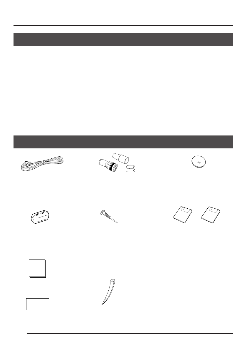
Accessories and attachments
0
2
2
R
5
C
Power cable (2 m)
For connecting with AC
adapter 8-pin cable
( Z page 18)
Ferrite core
For power cable
( Z page 18)
Instruction book
Warranty card
E6
Remote plug (10-pin)
REMOTE terminal plug
( Z page 12)
Mini screwdriver
For replacing battery
( Z page 16)
Wire clamp (5 units)
For clamping rear cables, etc.
Battery
For time and date backup
( Z page 16)
PC software (2 types)
• Remote control software
(For controlling the main unit
with a PC)
• SCSI import plug-in software
(For importing still images to
a PC)
For details, see the instructions
attached with the software.
( Z page 64)
Page 7

Cautionary notes for the correct usage of this product
• Before recording an important event, etc., always check to make sure that this product is
working properly.
• We are not liable for any missed recordings caused by malfunction of this unit, etc.
m Phenomena unique to CCD
• Smearing and blooming
When using CCD to record a bright light source, a smearing effect may occur running a
white line parallel to the light source. In addition, a b looming eff ect ma y also occur when the
light source is extremely bright, spreading light to the source surroundings.
• Line distortion
Line and patterns may appear distorted when recorded.
• White dots
White dots may appear on the screen when operating under high temperatures. Always
use the product under recommended ambient temperatures.
m Cautionary notes
• Influence of strong electric waves and magnets
Screen noise and discoloration may occur when using the product near antennas of radios
and televisions or near transformers, monitors, etc. with strong magnetic force.
• Compatible lenses ( Z page 17)
Although the lens mount of this product is a type C mount, take caution as there are restrictions on the lenses that can be used.
This product is not equipped with a back-focus adjustment feature. Please use a lens
equipped with the back-focus adjustment feature.
• Caring of the product (always turn off the power before cleaning)
Wipe the product with a soft cloth.
Do not use paint thinner or benzine as it may melt or discolor the surface.
For stubborn dirt, wipe with a cloth dampened with water-diluted neutral detergent, then
dry wipe.
m This product is a Type II information processing device (information processing device for use
in residential areas or nearby areas) conforms to the VCCI (Voluntary Control Council for
Interference by Information Technology Equipment) standards for the purpose of preventing
electrical interference in residential areas.
Howev er, using the product near televisions and radios may cause interference of reception.
Please read the instructions carefully for the correct usage.
E7
Page 8
1. Introduction (continued)
Part names and their functions
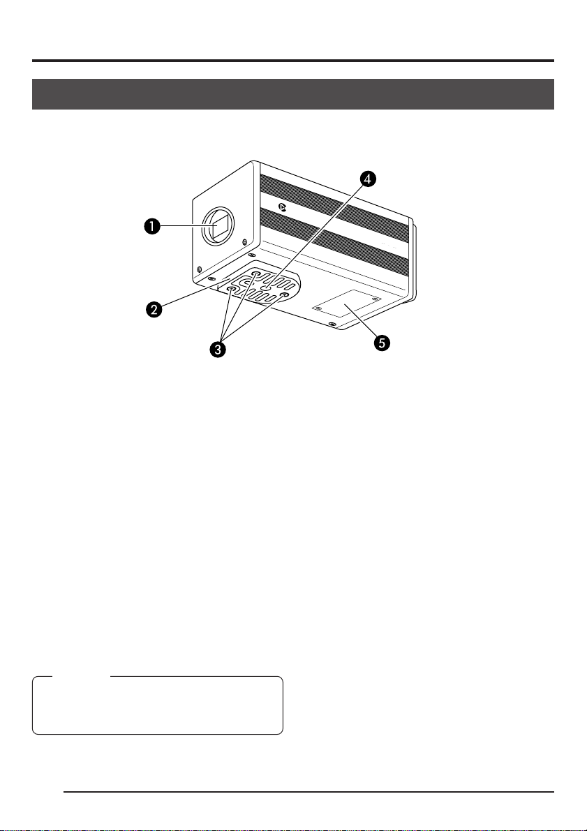
[Front and bottom]
C-MOUNT
@@@@@@
^ Lens mount
Although the lens mount conforms to the
type C mount lens, there are restrictions
on the lenses that can be used.
Mounting the lens ( Z page 17)
_ Camera mounting bracket
Although the mounting bracket is mounted
on the bottom of the camera when shipped,
the bracket can also be mounted on the
top of the camera.
Mounting the camera ( Z page 22)
` Locking screws for the camera
mounting bracket
(M2.6 × 6mm, 3 units)
CAMERADIGITAL
KY-F70
a Screw holes for mounting the
camera (1/4-inch)
Used when mounting the camera to a fixer
or rotating platform.
b Lithium battery case
Used to case the lithium battery for time
and date backup. The lithium battery is not
installed when shipped.
Please install the attached lithium battery
(CR2032) before use.
Inserting the lithium battery ( Z page 16)
CAUTION
Always use the attached screws. Using screws
that exceed 6mm may result in malfunction of
the unit.
E8
Page 9
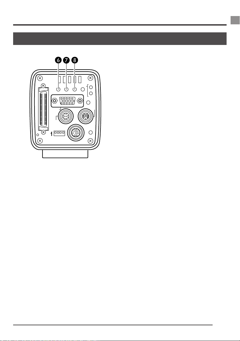
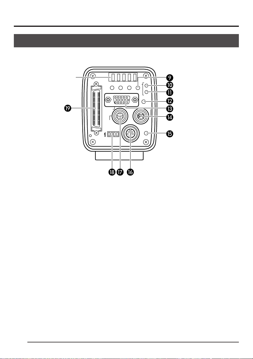
[Rear]
SCSI
AW/SELSEND
UPMENU
MONITOR
REMOTE
ON 1 2 3 4
SEE INSTRUCTION MANUAL
DC IN
MODE
SETDOWN
REC
PLAY
FREEZE
LENS
POWER
c MENU button
Press this button to output the menu screen
from the MONITOR terminal.
Press the button once more to clear the
menu screen.
Setting in the menu screen ( Z page 44)
d SEND/UP button
● Press this button to output the same still
image* that is being outputted to the
MONITOR terminal to an MO drive or
printer.
Save images in memory to an MO disk ( Z
page 36)
Output images in memory to a printer ( Z
page 37)
* A still image refers to an image recorded
by pressing the FREEZE button while in
the REC mode or an image being played
back in the PLAY mode.
● While the menu screen is being displayed, press this button selected item
up.
While an item is selected, use this button to change the set value.
Setting in the menu screen ( Z page 44)
e AW/SEL/DOWN button
● [AW (Auto White)]
Press this button to adjust the white balance when the light source of the subject is changed.
White balance adjustment ( Z page 28)
● [SEL (Select)]
Pressing this button each time while in
the PLAY mode will switch to the previous image in memory.
* The PLAY mode refers to the condition
which the unit is playing back recorded
images from the memory.
Playing back images from memory ( Z
page 33)
● [DOWN]
While the menu screen is being displayed, press this button selected item
down.
While an item is selected, use this button to change the set value.
Setting in the menu screen ( Z page 44)
E9
Page 10
1. Introduction (continued)
Part names and their functions (continued)
[Rear (continued)]
Ventilation hole
SCSI
@@@@@@
SEE INSTRUCTION MANUAL
f MODE/SET button
● [MODE]
Pressing this button each time will switch
between the REC (record)* and PLAY
(playback) modes. The default mode
when the power is turned on is REC.
* REC mode is the condition which the unit
has either captured an image or is ready
to write an image to the main unit memory.
Recording images to the main unit memory
( Z page 34)
Playing back images from the memory
( Z page 35)
● [SET]
While the menu screen is being displayed,
use this button to select a submenu or
confirm a selected item or set value.
Setting in the menu screen ( Z page 44)
MONITOR
REMOTE
ON 1 2 3 4
REC
MODE
AW/SELSEND
SETDOWN
UPMENU
DC IN
PLAY
FREEZE
LENS
POWER
g REC display lamp
This lamp lights when in the REC* mode.
During FREEZE, this display lamp will flash.
* During the REC mode, camera images
are outputted to the MONITOR terminal.
Pressing the FREEZE button at this time
will save the image to the main unit
memory.
h PLAY display lamp
This lamp lights when in the PLAY* mode.
* During the PLAY mode, images sav ed in
the main unit memory are played back
by outputting to the MONITOR terminal.
Playing back images from the memory ( Z
page 35)
E10
Page 11

i FREEZE button
While in the REC mode, press this button
to capture a still image (freeze) of the images being outputted through the MONITOR terminal. At the same time, the still
image is saved to the main unit memory.
Pressing this button once more will cancel
the still image and return to the camera
images.
Saving images to the main unit memory
( Z page 34)
MEMO
You can also set the unit to automatically cancel the still image after 5 seconds.
FREEZE screen, CANCEL screen ( Z page 53)
j MONITOR output terminal
(D-sub 15-pin, female)
Used to connect to a V GA monitor or SXGA
compatible capture board.
The default setting is set to VGA monitor
compatible. To change the setting from VGA
mode to SXGA mode, change the dip
switch settings.
Setting the monitor ( Z page 24)
● When in the SXGA mode, images of
1360 × 1024 pixles (7.5 frames/sec.) are
outputted.
● For the VGA mode, you can select between the FINE mode of 640 × 480 pixels (7.5 frames/sec.) or DRAFT mode of
640 × 240 pixels (30 frames/sec.) in the
menu screen.
Setting the VGA mode ( Z page 25)
k LENS connection terminal
Used to connect the lens cable.
Mounting the lens ( Z page 17)
l POWER display lamp
This lamp lights when the power of the main
unit is on.
m DC IN power input terminal
(Mini DIN 8-pin, female)
Main unit power supply (DC 12V) is supplied through this terminal.
For the power supply, use the AA-P700 AC
adapter.
Connecting the power ( Z page 18)
n REMOTE terminal
(Metal 10-pin, female)
Used to connect external devices such as
a freeze switch or flash unit.
5. Various recording methods ( Z page 40)
o Dip switches
Used to set the SCSI ID ( Z page 24) and
monitor ( Z page 24), and output color bar
( Z page 28).
p SCSI terminal
(Half-pitch 50-pin × 2)
Used to directly output to an MO drive ( Z
page 20) or printer ( Z page 21).
The default setting of the SCSI ID is 7.
Change the SCSI ID setting when connecting to a PC, etc.
Connecting to a PC ( Z page 64)
E11
Page 12
1. Introduction (continued)
6
7
8
2
1
9
3
4
12
5
10
11
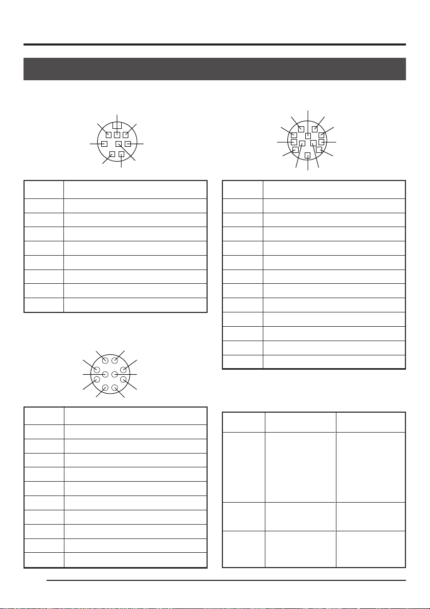
Explanation of terminals
Po wer terminal (Mini DIN 8-pin, f emale)
7
8
5
2
@@@@@@
6
3
4
1
Pin no. Signal name
1NC
2 GND
3NC
4NC
5 GND
6 12V
7NC
8 12V
Remoter terminal (Metal 10-pin, female)
8
7
10
6
5
1
2
9
3
4
Lens terminal (Metal 12-pin, female)
Pin no. Signal name
1NC
2
3 GND
4NC
5 IRIS CONTROL
6 12V DC
7 IRIS POSITION
8 IRIS AUTO /MANU
9NC
10 NC
11 NC
12 NC
Pin no. Signal name
1 A. WHITE active Zi=22k Ω
2 FREEZE L active Zi=100k Ω
3
WEN L active Zo=100 Ω 3V(p-p)
4 FLASH
5 SEND (PRINT)
6 RS-SDI
7 RS-SDO
8 GND
9 12V
10 OPERATION
E12
Terminal
name
FREEZE
WEN
FLASH
I/O
IN
• 5V CMOS
• Schmidt T rigger
• Pull-up to 5V at
100k Ω
• Input capacity
0.1 µF
OUT
• 3.3V (p-p)
negative polarity
OUT
• Open collector
Conditions
• Contact point
recommended
• Rated voltage:
5.3V
• H level: 3.5 ~ 5.0V
• L level: 0 ~ 0.8V
• CMOS (5V): OK
• TLL not possible
• Output only when
in the SXGA mode
• Rated current:
150mA
• Rated voltage:
12V
Page 13
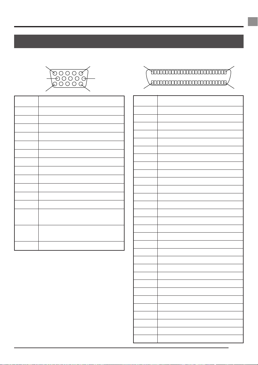
Monitor terminal (D-sub 15-pin, female)
15
SCSI terminal (Half-pitch 50-pin, female)
25
1
10
15
6
11
Pin no. Signal name
1 R OUT 700mV, 75 Ω
2 G OUT 700mV, 75 Ω
3 B OUT 700mV, 75 Ω
4 GND
5NC
6 R GND
7 G GND
8 B GND
9NC
10 GND
11 GND
12 NC
13 Hs (3V(p-p) negative polarity
Zo=100 Ω)
14 Vs (3V(p-p) negative polarity
Zo=100 Ω)
15 NC
2650
Pin no. Signal name
1 ~ 11 GND
12 GND
13 NC
14 GND
15 ~ 25 GND
26 DB 0
27 DB 1
28 DB 2
29 DB 3
30 DB 4
31 DB 5
32 DB 6
33 DB 7
34 DBP
35 GND
36 GND
37 GND
38 VC +5 (input only)
39 GND
40 GND
41 ATN
42 GND
43 BSY
44 ACK
45 RST
46 MSG
47 SEL
48 CD
49 REQ
50 I/O
E13
Page 14
2. Before recording
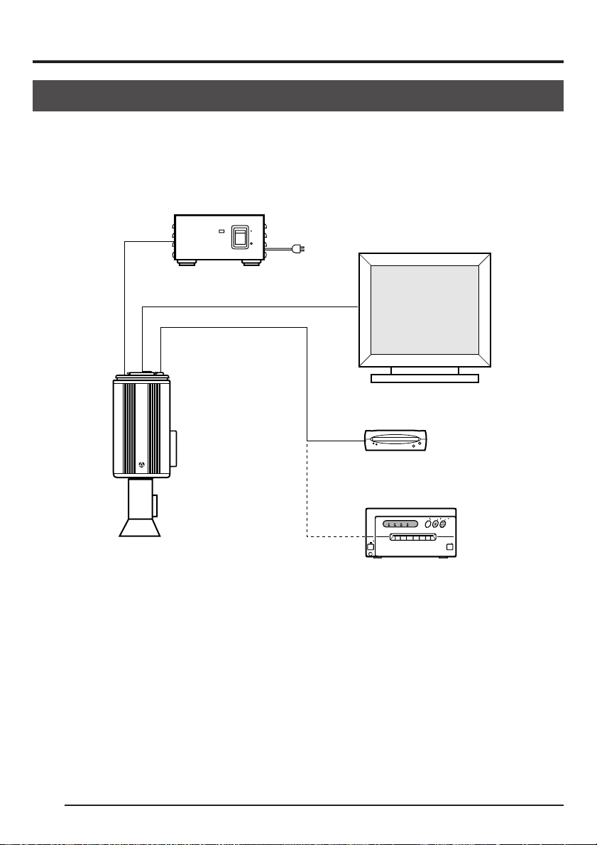
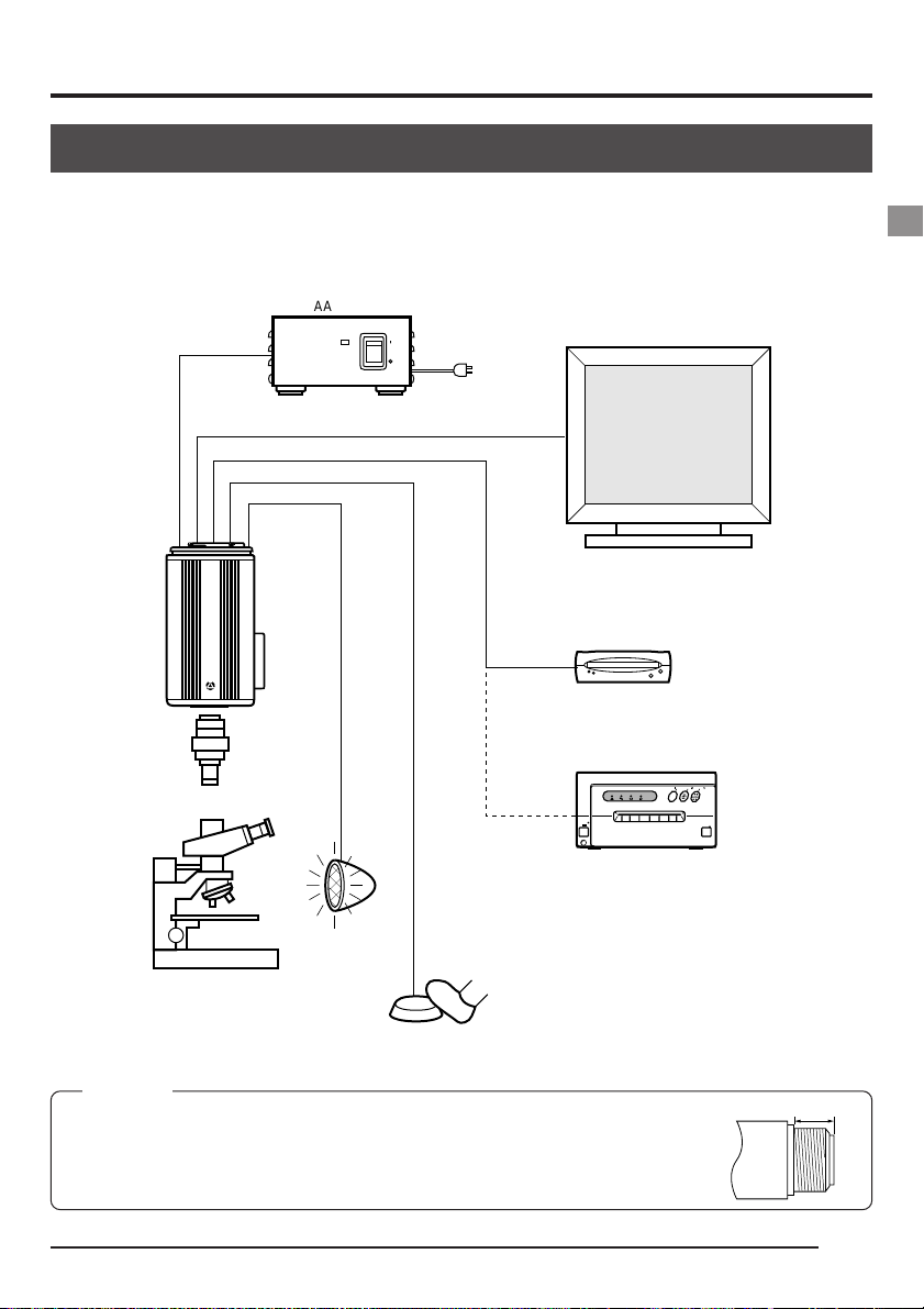
Basic system 1
While checking the images from the camera on the monitor , output the images to an MO disk or
printer.
Connect to the
power supply
( Z page 18)
@@@@@@
MONITOR VIDEO IN
DC IN
KY-F70
CAMERADIGITAL
C-MOUNT
AA-P700
AC adapter
SCSI
Mount the lens
( Z page 17)
POWER
ON
OFF
AC ADAPTER AA-P700
AC
Connect the monitor
( Z page 19)
VGA monitor
Connect the MO drive
unit ( Z page 20)
MO disk drive
CP700DSAMITSUBISHI
]
PAPER
ALARM SHEET
POWER
ONLINECOPY & CUTPAPER FEED
DATA
OPEN
Printer
(recommended: Mitsubishi CP700DSA)
Connect the printer
( Z page 21)
For the power supply, always use the AA-P700 AC adapter.
E14
Page 15
Basic system 2
This is a system to record with this camera using a flash timed by an external freeze switch.
AA-P700
AC ADAPTER AA-P700
POWER
ON
OFF
AC
Model name
DC IN
MONITOR
SCSI
REMOTE
KY-F70
CAMERADIGITAL
C-MOUNT
Microscope
adapter
REMOTE
AC adapter
Flash
Freeze switch
VGA monitor
MO disk drive
PAPER
ALARM SHEET
DATA
POWER
Printer
CP700DSAMITSUBISHI
]
ONLINECOPY & CUTPAPER FEED
OPEN
CAUTION
Use a 1/2 inch mount microscope adapter.
To avoid damage to the unit, always use an adapter that is 4mm or less from
the lens mount side.
4mm or less
Lens
E15
Page 16
2. Before recording (continued)
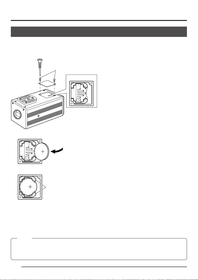
Inserting the lithium battery
The lithium battery is used to back up the time and date data.
Install the lithium battery before using the unit.
<
Install
>
1.
@@@@@@
C-MOUNT
2.
5
2
0
2
R
C
3.
5
2
0
2
R
C
Mini screwdriver (attached)
Screws
Battery compartment
CAMERADIGITAL
KY-F70
Remove the screws (2 units) using the attached mini screwdriver, then open the cover.
Completely insert the lithium battery in the direction of the arrow with the + side facing up.
Make sure that the battery is securely in position by the hold-
Holders
ers as shown in the diagram.
(To remove the battery, follow the procedure in reverse.)
4.
Replace the cover and retighten the screws.
MEMO
The time and date will not be displayed correctly when the battery is not installed. When replacing the
lithium battery, reset the time and date.
Setting the time and date ( Z page 26)
E16
Page 17
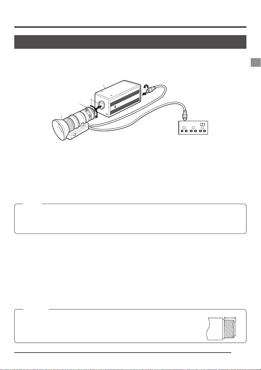
Mounting the lens
Follow the procedure shown belo w when mounting an auto-iris lens. For further details, see the
instruction manual of the lens.
Camera head
Thread section
Mount clamp ring
Lens
1.
Remove the lens mount cap. At this time, take caution so that dust do not enter inside the
C-MOUNT
2.
Male
3.
KY-F70
CAMERADIGITAL
Female
Lens remote control
mount.
2.
To mount the lens, lightly press the thread section of the lens mount onto the thread section
of the main unit, then turn the mount clamp ring slowly clockwise until it is securely tight-
ened.
MEMO
To change the position of the lens rotation:
~ First, turn the mount clamp ring counterclockwise (1/4 turns) with the lens facing you.
Ä Slowly turn the lens and after adjusting the position, retighten the mount clamp ring.
3.
Insert the camera cable of the lens into the lens connection terminal on the rear of the main
unit, then securely fasten.
The iris control is made automatically from the camera.
* When using a manual iris lens, set the IRIS MODE to MANUAL (see Z page 48).
4.
When using the lens remote control, connect the lens control cable (female) to the remote
control.
CAUTION
Lens is not included with this unit.
To avoid damaging the main unit, make sure that the lens mount of the lens to be
used is 4mm or less.
4mm or less
Lens
E17
Page 18
2. Before recording (continued)
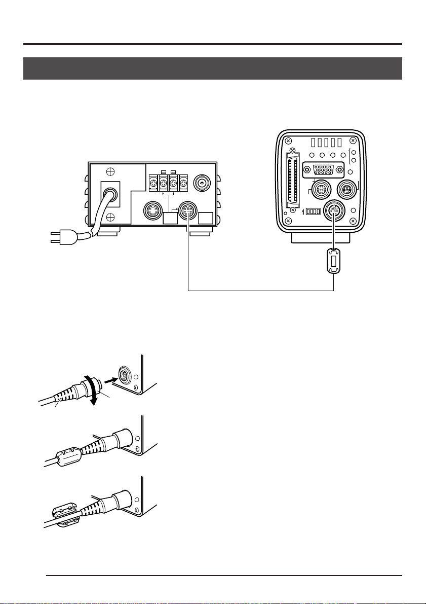
Connecting the power
Connect the DC IN terminal on the rear of the main unit and the TO CAMERA terminal of the A C
adapter (AA-P700) with the attached power supply cable (2m).
@@@@@@
AC 100V
AA-P700
DC 12V=OUTPUT
EITHER
OUTPUT
MAX 1.25A
TO CAMERAS(Y/C) OUTPUT
VIDEO OUTPUT
SEE INSTRUCTION
MANUAL
SCSI
MONITOR
REMOTE
ON 1 2 3 4
SEE INSTRUCTION MANUAL
REC
MODE
AW/SELSEND
SETDOWN
UPMENU
PLAY
FREEZE
LENS
DC IN
POWER
AC adapter
AC
Clamp filter
Attached power supply cable
Before connecting, make sure that the power switch of the AA-P700 is set to OFF. Connecting
with the power turned on may result in malfunction.
Plug
Ring
DC IN
DC IN
POWER
POWER
After inserting the plug completely, securely fasten by
turning the ring.
T o reduce emission of unw anted electrical waves , mount
the attached ferrite core as shown in the diagram on
the left.
E18
DC IN
POWER
Mount the ferrite core as close to the main unit as possible as shown in the diagram.
Connect the plug to the AC adapter side in the same
manner.
Page 19
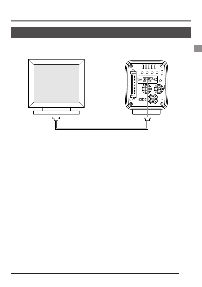
Connecting a monitor
Connect the PC monitor (VGA) to the MONITOR terminal on the rear of the main unit.
SCSI
UPMENU
MONITOR
REMOTE
ON 1 2 3 4
SEE INSTRUCTION MANUAL
AW/SELSEND
DC IN
MODE
SETDOWN
REC
PLAY
FREEZE
POWER
LENS
MONITOR terminal
● Before connecting, make sure that the power of all systems are turned off. Connecting with the
power turned on may result in malfunction.
● For the connector, commercially available VGA video cable is recommended.
● For the pin assignment, see page 13 Explanation of terminals
E19
Page 20
2. Before recording (continued)
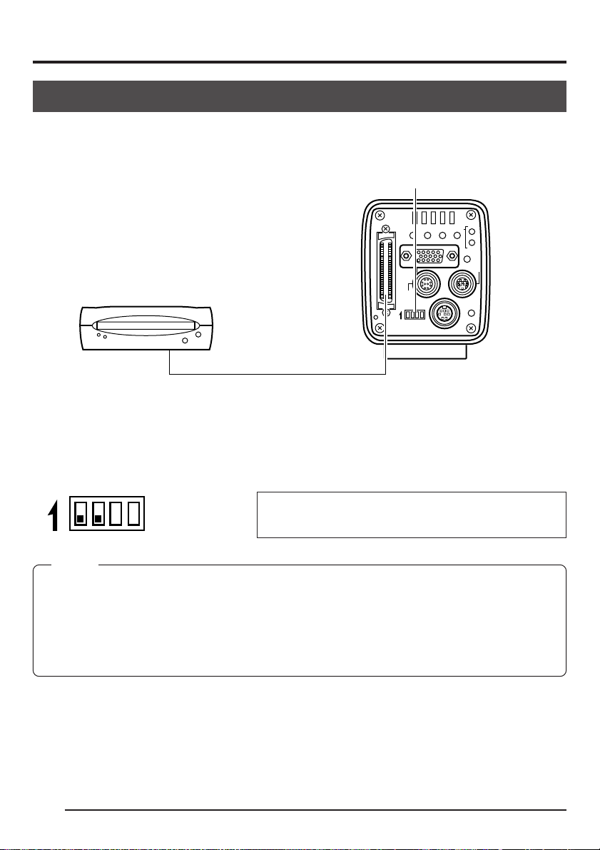
Connecting an MO drive unit
It is possible to output image data stored in the main unit memory to an MO drive unit. ( Z Page
36 Saving images from the memory to an MO disk)
Dip switches
@@@@@@
SCSI
UPMENU
MONITOR
REMOTE
ON 1 2 3 4
SEE INSTRUCTION MANUAL
AW/SELSEND
DC IN
MODE
SETDOWN
REC
PLAY
FREEZE
POWER
LENS
SCSI terminal
To directly connect the MO drive to the main unit, set the dip s witches on the rear of the main unit
as shown below.
ON 1 2 3 4
(SCSI : 7)
MEMO
• The image data outputted to an MO drive will be 1360 × 1024 pixels, regardless whether the monitor
in use is VGA or SXGA, or whether the VGA mode is set to FINE or DRAFT.
• The maximum allowed length of the SCSI cable is 3m.
• When connecting an MO drive to a PC, separate setting of the SCSI ID is required.
( Z Page 64 7. Connecting to a PC)
• It is not possible to simultaneously output the image data to a printer and MO drive.
Do not set the ID of the MO drive side to other than
7.
E20
Page 21
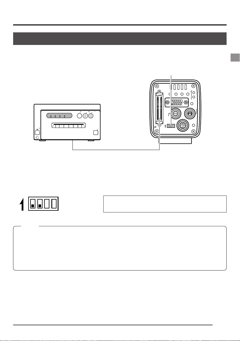
Connecting a printer
It is possible to directly output image data stored in the main unit memory to a printer. ( Z page
37 Outputting images from the memory to a printer)
Dip switches
SCSI
UPMENU
CP700DSA
MITSUBISHI
]
ONLINECOPY
PAPER
ALARM SHEET
DATA
POWER
& CUTPAPER FEED
OPEN
MONITOR
REMOTE
ON 1 2 3 4
SEE INSTRUCTION MANUAL
AW/SELSEND
DC IN
MODE
SETDOWN
REC
PLAY
FREEZE
POWER
LENS
SCSI terminal
When directly connecting the main unit to a printer, set the dip s witches on the rear of the main
unit as shown below.
ON 1 2 3 4
(SCSI : 7)
MEMO
• The image data outputted to a printer will be 1360 × 1024 pixels, regardless whether the monitor in
use is VGA or SXGA, or whether the VGA mode is set to FINE or DRAFT.
• The maximum allowed length of the SCSI cable is 3m.
• When connecting an MO drive to a PC, separate setting of the SCSI ID is required.
( Z Page 64 7. Connecting to a PC)
• It is not possible to simultaneously output the image data to a printer and MO drive.
Set the ID of the printer side to other than 7.
E21
Page 22

2. Before recording (continued)
Mounting the camera
<
Mounting method
Rotation prevention hole
>
Camera mounting screw hole
@@@@@@
Camera mounting bracket
● When mounting the camera, use the camera mount screw hole located on the camera mounting bracket.
● When mounting the camera, use the rotation prevention hole to prevent the unit from falling
and securely mount the unit.
<
Changing the camera mounting bracket position
>
E22
C-MOUNT
When shipped, the camera mounting bracket
is mounted on the bottom of the unit. To mount
it on the top of the unit, simply remove the 3
locking screws holding the camera mounting
CAMERADIGITAL
KY-F70
bracket.
CAUTION
Always use the screws mounted on the main
unit. Using screws that exceed 6mm in length
may result in damage to the unit.
Page 23

Fall prevention
Fall pre vention
wire chain
6mm
Camera head
C-MOUNT
CAMERADIGITAL
KY-F70
Notes
● Special attention is required when mounting the unit to the wall or ceiling.
Rather than attempting to do it yourself, request a qualified person to
perform such installation. Falling of the unit may result in bodily injury.
● To prevent the unit from falling, connect the unit to a strong surface with a
wire chain, etc. When connecting such chain, use the brac ket locking scre w
hole on the side which the camera mounting bracket is not mounted.
(M2.6 × 6mm)
Take special caution to the length of the wire as well.
E23
Page 24

3. Settings and adjustments for recording
Setting the dip switches
The type of PC monitor to use and the ID during SCSI connection are set using the dip switches.
SCSI
MONITOR
REMOTE
Dip switches
@@@@@@
ON 1 2 3 4
SEE INSTRUCTION MANUAL
REC
MODE
AW/SELSEND
SETDOWN
UPMENU
PLAY
FREEZE
LENS
DC IN
POWER
MEMO
Turn the power off before setting the dip s witches . Setting
the switches with the power on will not change the settings.
Monitor settings
Dip switch no. 3 is set depending on whether the PC monitor being used is a VGA monitor or a
SXGA monitor. <Default setting: OFF
ON 1 2 3 4
VGA output terminal
>
Set when directly connecting a VGA monitor to the MONITOR terminal on the rear of the main unit.
Set to OFF
SXGA output setting
ON 1 2 3 4
Set for systems using a SXGA monitor.
The signal from the MONITOR terminal on the rear of the main unit
is inputted through the analog input compatible video capture board.
Set to ON
( Z Page 65 Compatible systems 2)
SCSI ID settings
Sid switches 1 and 2 are set depending on the used system to set the SCSI ID. <Default ID: 7
ON 1 2 3 4
ON 1 2 3 4
ID=7
ID=6
Set when connecting a printer or MO drive directly to the main unit.
When making this setting, the main unit will become the host (initiator).
Set when exporting images to a PC.
ON 1 2 3 4
ID=5
ON 1 2 3 4
ID=4
Make sure that the ID numbers of the connecting devices are not
the same.
When making this setting, the PC will become the host (initiator)
and the main unit will become the target.
( Z Page 64 Connecting to a PC)
E24
>
Page 25

Menu settings
VGA mode and lens settings are made from the menu screen.
VGA mode settings
Set whether to output semi-animation (7.5 frame/sec.) of 640 × 480 pixels or full-motion video
(30 frames/sec.) of 640 × 240 pixels to the connected VGA monitor.
--- ETTING ---SYSTEM S
ON SCREEN
FRZ DI SPL AY
SEND PR I OR
MON I TOR
BAR LEVEL
NEGA
MENU RE
S
ET
VIDEO ME
MOR
ITMEADJUST
MEMORY NUM
::O
N
ITY
:MO
:FINE
:0.7V
:OFF
..
Y
RCLEA ..
Set MONITOR in the SYSTEM SETTING screen.
FINE: Semi-animation (7.5 frames/sec.) of 640 × 480
pixels
DRAFT: Full-motion video (30 frames/sec. of 640 × 240
pixels
(Default setting: DRAFT)
MEMO
This menu item will be displayed with ———— when set to the SXGA mode by the rear dip switches,
disabling changes.
Lens settings
Set whether the used lens is an auto-iris lens or a manual lens.
--- ---EXPOSURE
IRIS MODE : AU
AE LEVEL
IRIS LEVEL
IRIS DETECT
IRIS AREA
SHUTT ER
SPEED
LEVEL
ITY
SENCET I V
ALC MAX
:0
:128
:NORM1AL
:FULL
:STEP
:1/8
:ISO
TO
P:STE
00
400:ISO
Set IRIS MODE in the EXPOSURE screen.
AUTO: Set when using an auto-iris lens
MANU: Set when using a manual lens or no lens.
(Default setting: AUTO)
E25
Page 26

3. Settings and adjustments for recording (continued)
Time and date settings
DOWN
MENU
UP
MODE/SET
SCSI
MONITOR
@@@@@@
REMOTE
ON 1 2 3 4
SEE INSTRUCTION MANUAL
ON SCREEN
PRI OR ITY
SEND
BAR L EVE L
MENU RESET . .
V I DEO MEMORY CLEAR . .
T IME ADJUST. .
REC
MODE
AW/SELSEND
SETDOWN
UPMENU
PLAY
FREEZE
LENS
DC IN
POWER
TEMSYS--- MENU ---
MEMORY N
::MO
:0.7V
PLAY menu screen
PLAY
U
M
1.
Press the MODE button to enter the PLAY mode (PLAY
LED on), then press the MENU button. The PLAY menu
screen will be outputted through the MONITOR terminal.
2.
Press either the UP or DOWN button and select TIME
ADJUST (when selected, the TIME ADJUST displa y will
become purple). Next, press the SET button to display
the TIME ADJUST screen.
(The TIME ADJUST screen can also be displayed by
selecting TIME ADJUST in the SYSTEM SETTING
screen of the REC mode.)
3.
The year will be displayed in purple to indicate that it
can be changed. Press the UP or DOWN button to set
the year.
4.
When the year setting is completed, press the SET button. The year displa y will return to white and the month
will be displayed in purple to indicate that it can be
changed. In the same manner as above, press the UP
or DOWN button to set the month.
--- TIME ADJUST ---
ADJUST T I ME
1999/12/31 23:59:
ADJUST [UP ]
SET [SET ]
•
EXI T [ MENU]
TIME ADJUST screen
E26
[DOWN]
5.
Set the day, hour and minute in the same manner. The
seconds display will display 00. The clock will start when
the 00 is displayed in purple and the SET button is
00
pressed. Press the SET button when the actual time
reaches 00 seconds.
Page 27

6.
OK will be displayed for approximately 3 seconds and
--- TIME AOKDJUST ---
OK display screen
MEMO
When setting the time and date, always set the seconds (00).
Pressing the MENU button before setting the seconds will not change the set values.
the unit will return to the menu screen.
E27
Page 28

3. Settings and adjustments for recording (continued)
Monitor adjustment
The color contrast, brightness, etc. are adjusted by sending built-in color bar signals of the main
unit to the PC monitor.
MONITOR terminal
SCSI
@@@@@@
MONITOR
REMOTE
ON 1 2 3 4
SEE INSTRUCTION MANUAL
Dip switches
REC
MODE
AW/SELSEND
SETDOWN
UPMENU
PLAY
FREEZE
DC IN
POWER
LENS
1.
Depending on the system, set the MONITOR mode to
VGA or SXGA.
(Set using the main unit dip switches)
Monitor settings ( Z page 24)
2.
Connect the monitor and MONITOR terminal.
3.
Set dip switches 3 and 4 on the rear of the main unit to
ON.
ON 1 2 3 4
MEMO
Turn the power off before setting the dip switches. Setting the
switches with the power on will not change the settings.
4.
Turn the main unit power on.
5.
Adjust the video monitor.
MEMO
• For the adjustment method, see the instruction manual of
the video monitor.
• The peak level of the color bar is et to 0.7V. To change the
setting to 0.58V, select BAR LEVEL in the SYSTEM SETTING screen ( Z Page 58).
E28
6.
When completed, turn off the system power., then set
dip switch 4 to OFF.
Page 29

Focus adjustment
This unit is not equipped with a back-focus feature. Adjust the back focus using the lens.
Male
KY-F70
CAMERADIGITAL
Focus ring
Shutter speed
REC--- MENU(QUICK)---
AE LEVEL
IRIS LEVEL
SHUTERE :
SPEED
SENS I T I V I TY
LEVEL : I SO100
ALC MAX : I SO4 0 0
SEND PRIORITY: MO
:
128
:
S0TE
:1/3
: STEP
P
0
REC mode quick menu screen
C-MOUNT
Female
The default setting of the main unit shutter speed is 1/8.
When difficult to focus, change the shutter speed to 1/30
using the procedure given below.
1.
Press the MODE button to enter the REC mode (REC
LED on). Ne xt, lightly press the MENU b utton to displa y
the REC mode quick menu screen.
2.
Press the DOWN and SET buttons to change SHUTTER to STEP.
3.
Press the DOWN button to select SHUTTER SPEED,
then press the SET button.
1/8 will be displayed in purple, indicating that it can be
changed.
4.
Press the UP or DOWN button to change the value to
1/30, then press the SET button. When confirmed, the
set value of 1/30 will be displayed in white.
MEMO
At this time, pressing the MENU button without pressing the
SET button will not confirm the set value and the unit will return to the setting prior to the change.
5.
Press the MENU button to return to the normal screen.
E29
Page 30

3. Settings and adjustments for recording (continued)
White balance adjustment
Since the color of light (light temperature) changes depending on the light source, readjust the
white balance (AUTO WHITE) when the light source of the object changes.
DOWN
MENU
UP
MODE/SET
SCSI
@@@@@@
MONITOR
REMOTE
ON 1 2 3 4
SEE INSTRUCTION MANUAL
1 : EXPOSURE . .
2 :WHI TE BALANCE. .
3 : FREEZE . .
4 : PROCESS . .
5 : SYSTEM SETT I NG. .
REC
MODE
AW/SELSEND
SETDOWN
UPMENU
PLAY
FREEZE
LENS
DC IN
POWER
REC--- MENU---
REC MENU screen
Menu item
COLOR TEMP
WH I T E B A L ::AUTO
LEVEL (R)
LEVEL ( B )
SHANDI NG
LEVEL (R)
LEVEL ( G )
LEVEL ( B )
Set value
-- ---CE-WHI TE BALAN
MODE
3200K
:0
:0
:OFF
:
:
:
REC LED
1.
Press the MODE button to enter the REC mode (REC
LED on), then press and hold the MENU button for at
least 2 seconds to display the REC MENU screen.
(If the button is pressed for less than 2 seconds, the
REC mode quick menu will appear. Z Page 47)
2.
Press the DOWN button, select 2. WHITE BALANCE
(the text will be display ed in purple when selected), then
press the SET button.
The WHITE BALANCE screen will appear.
3.
Press the UP or DOWN button to select COLOR TEMP
(the text will be display ed in purple when selected), then
press the SET button.
The set value will be display ed in purple, indicating that
it can be changed.
4.
Press the UP or DOWN button to select the setting depending on the usage environment.
3200K: when using low temperature lighting such as a
halogen lamp, etc.
5200K: when using high temperature lighting such as
the sun, etc.
Pressing the SET button will register the setting in the
main unit memory.
MEMO
Pressing the MENU button without pressing the SET button
will not register the set value and the unit will return to the
setting prior to the change.
WHITE BALANCE screen
E30
5.
Press the UP/DOWN and SET buttons to set WHITE
BAL in the WHITE BALANCE screen to AUTO.
Page 31

AW
SCSI
MONITOR
REMOTE
ON 1 2 3 4
SEE INSTRUCTION MANUAL
AW/SELSEND
UPMENU
DC IN
WHIAUTO ET
RATOPE ION
REC
MODE
SETDOWN
PLAY
FREEZE
LENS
POWER
Auto white in operation
WHAUTO TIE
OK
6.
After pressing the MENU button twice to return to the
normal screen, place a white object with the same lighting conditions as the object to record, then zoom in to
display white on the screen.
7.
Press the AW (Auto White) button.
● When auto white is in operation, OPERATION will be
displayed on the monitor screen.
● When the white balance is successfully set, OK will
appear on the screen and the unit will return to the
normal screen.
MEMO
When setting the VGA mode to FINE, using the SXGA mode
or setting the unit to a slow shutter speed, the white balance
operation may take some time before completion.
● Error display
When the auto white balance cannot be set, one of
the following error messages will appear and the unit
will return to the normal screen.
NG: OBJECT (bad object)
Displayed when the object consists of little whiteness
or when the color temperature is not correct.
Change to a white object and redo the white balance.
Auto white operation completed
ERROR: LOW LIGHT (shortage of light)
Displayed when the lighting is too dark. Brighten the
lighting and redo the white balance.
ERROR: OVER LIGHT (excessive light)
• Displayed when the lighting is too bright. Lo w er the
brightness and redo the white balance.
• If the color temperature of the object changes when
darkening the lighting, redo the white balance after
pressing the AW button on the panel.
E31
Page 32

3. Settings and adjustments for recording (continued)
White shading adjustment
Even if the white balance is successfully achieved in the center of the screen, there may be
times when white balance cannot be achieved at the top and bottom of the screen, resulting in
the color of green and magenta becoming discolored. This is due to the characteristic of the lens
and the adjustment of this is called the white shading adjustment.
DOWN
MENU
@@@@@@
SCSI
MONITOR
REMOTE
ON 1 2 3 4
SEE INSTRUCTION MANUAL
1 : EXPOSURE . .
2 :WHI TE BALANCE. .
3 : FREEZE . .
4 : PROCESS . .
5 : SYSTEM SETT I NG. .
SET
REC
MODE
AW/SELSEND
SETDOWN
UPMENU
PLAY
FREEZE
LENS
DC IN
POWER
REC--- MENU ---
REC MENU screen
REC LED
Perform the following after adjusting the white balance.
1.
Press the MODE button to enter the REC mode (REC
LED on), then press and hold the MENU button for at
least 2 seconds to display the REC MENU screen.
(If the button is pressed for less than 2 seconds, the
REC mode quick menu will appear. Z Page 38)
2.
Press the DOWN button, select 2. WHITE BALANCE
(the text will be display ed in purple when selected), then
press the SET button.
The WHITE BALANCE screen will appear.
3.
Press the UP/DOWN and SET buttons to set SHADING MODE in the WHITE BALANCE screen to ADJUST.
The set value will be display ed in purple, indicating that
it can be adjusted.
E32
Page 33

-- ---CE-WHI TE BALAN
COLOR TEMP
WH I T E B A L ::AUTO
LEVEL (R)
LEVEL ( B )
SHANDI NG
LEVEL (R)
LEVEL (G )
LEVEL ( B )
MODE
3200K
:0
:0
:ADJUST
:0
:0
:0
WHITE BALANCE screen
4.
While watching the monitor screen, change LEVEL (R),
LEVEL (G) and LEEL (B) using the UP and DOWN
buttons.
For each item, the color at the bottom weakens and the
color at the top strengthens as the number becomes
larger
<
Variable range: –128 ~ 127
5.
When the adjustments of all channels (R, G and B chan-
>
nels) are completed, redo the white balance adjustment.
E33
Page 34

4. Basic operations
Recording images to the main unit memory
The main unit is capable of storing 5 images in the VGA mode and 4 images in the SXGA mode
to the main unit memory.
Exceeding the maximum number of images stored will replace the oldest image with the latest.
1.
MODE
SCSI
@@@@@@
MONITOR
REMOTE
ON 1 2 3 4
SEE INSTRUCTION MANUAL
REC
MODE
AW/SELSEND
SETDOWN
UPMENU
PLAY
FREEZE
LENS
DC IN
POWER
REC LED
FREEZE
Press the MODE button to enter the REC mode.
The REC LED will light.
MEMO
The unit will automatically enter the REC mode when the power
is turned on.
2.
Press the FREEZE button.
Images outputted through the MONITOR terminal will
become a still image and stored in the main unit memory .
In addition, the REC LED will flash.
At this time, FREEZE will appear in the screen. To disable the message from appearing, set FRZ DISPLAY
to OFF ( Z page 57).
MEMO
The character display contents of the monitor screen can be
changed by selecting ON SCREEN in the SYSTEM SETTING
screen. ( Z Page 57)
ZEFREE
FREEZE display
3.
Cancel FREEZE
Press the FREEZE button once more to cancel the still
image.
MEMO
It is possible to set the unit so that the still image is automatically cancelled after 5 seconds. Set CANCEL in the FREEZE
screen to AUTO. ( Z Page 53)
4.
Output the image to an MO drive or printer, as necessary.
( Z Pages 36 and 37)
CAUTION
Images stored in memory will be deleted when the power is turned off.
E34
Page 35

Playing back images from the memory
It is possible to play back images stored in the main unit memory. When in the VGA mode,
images will be displayed in 640 × 480 pix els, regardless of whether in the FINE or DRAFT mode .
1.
Press the MODE button to enter the PLAY mode.
The PLAY LED will light and the latest image stored will
be displayed on the monitor.
● At this time, the memory image no. will be displayed
at the bottom right of the screen.
MEMO
The character display contents of the monitor screen can be
changed by selecting ON SCREEN in the SYSTEM SETTING
screen. ( Z Page 57)
2.
Pressing the SEL button each time will switch the from
latest image to the others recorded previously in order.
3.
Images for playback can also be outputted to an MO
drive or printer ( Z pages 36 and 37).
SCSI
UPMENU
MONITOR
REMOTE
ON 1 2 3 4
SEE INSTRUCTION MANUAL
SEL
AW/SELSEND
DC IN
MODE
REC
MODE
SETDOWN
PLAY
FREEZE
LENS
POWER
PLAY LED
Returning to the REC mode
To return to the REC mode when displaying images, press
the MODE button to light the REC LED.
SCSI
UPMENU
MONITOR
REMOTE
ON 1 2 3 4
SEE INSTRUCTION MANUAL
MODE
MODE
AW/SELSEND
SETDOWN
DC IN
REC
PLAY
FREEZE
POWER
REC LED
LENS
E35
Page 36

4. Basic operations (continued)
Saving images from the memory to an MO disk
It is possible to save images stored in the main unit memory to an MO drive connected via the
SCSI terminal when in the FREEZE or PLAY mode.
(To output to an MO drive connected to a PC, see Page 64 7. Connecting to a PC)
SEND
MENU
@@@@@@
SCSI
terminal
SCSI
MONITOR
REMOTE
ON 1 2 3 4
SEE INSTRUCTION MANUAL
Dip switches
OK : "MODE
CANCEL: "MENU "
Output confirmation
Output in operation
MODE
AW/SELSEND
UPMENU
DC IN
ETOWR I T MO
OK?
ETOWR I T MO
AT I OOPER N
REC
MODE
SETDOWN
PLAY
FREEZE
LENS
ON 1 2 3 4
POWER
Undefined
"
m Set to either the FREEZE or PLAY mode.
1.
Check to make sure that dip switches 1 and 2 are set to
OFF as shown in the diagram on the left.
2.
Press the SEND button. WRITE TO MO OK? message
will appear on the monitor connected to the MONITOR
terminal.
3.
To write to the MO, press the MODE button (to cancel,
press the MENU button). While in operation, WRITE T O
MO OPERATION will appear for approximately 3 seconds.
4.
When data is successfully written to the MO, WRITE
TO MO OK FILE NAME: F70MMMM.TIF will appear for
approximately 3 seconds. (each M indicates a number)
5.
When data is not successfully written to the MO, one of
the following error messages will appear for approximately 3 seconds.
ERROR : SCSI (check the cable)
ERROR : WRITE (write error)
ERROR : FORMAT (format the disk)
ERROR : DISK (bad MO disk)
ERROR : DIRECTRY (directory error)
ERROR : READ (read error)
ERROR : MO (Other MO disk error)
Output completed
E36
ETOWR I T MO
OK
NAMFILE :E07F000IFT1.
Page 37

Outputting images from the memory to a printer
Use a printer with an SCSI input terminal.
It is possible to directly output images stored in the main unit memory to a printer connected via
the SCSI terminal when in the FREEZE or PLAY mode.
(To output to a printer connected to a PC, see Page 64 7. Connecting to a PC)
m Set to either the FREEZE or PLAY mode.
1.
Check to make sure that dip switches 1 and 2 are set to
OFF as shown in the diagram on the left ( Z page 36).
2.
Press the SEND button. PRINT OK? message will appear on the monitor connected to the MONITOR terminal.
3.
To pr int, press the MODE button (to cancel, press the
MENU button).
While in data is being written, PRINT OUT OPERA TION
will appear for approximately 3 seconds.
4.
When data is successfully outputted to the printer,
PRINT OUT will appear for approximately 3 seconds.
5.
When data is not successfully outputted to the printer,
one of the following error messages will appear f or approximately 3 seconds.
ERROR : SCSI (check the cable)
ERROR : PRINTER (printer error)
Print confirmationPrint in operation
PRINT
OK?
OK : "MODE "
CANCEL: "MENU "
P
RINRTTOUT
AION
OPE
PRINOKTOUT
Print completed
MEMO
• Set the SCSI ID of the MO drive or printer to other than 7.
• IF both MO drive and printer are connected to the SCSI terminal, select which source to output to by
selecting SEND PRIORITY in the SYSTEM SETTING screen ( Z Page 57; default setting: MO).
• Do not connect devices other than printers and MO drives to the SCSI terminal since correct output
will not be achieved. In addition, only one output device may be connected per one unit.
E37
Page 38

4. Basic operations (continued)
Clearing images from the memory
This function will clear all images stored in the main unit memory.
DOWN
MENU
UP
MODE/SET
SCSI
@@@@@@
MONITOR
REMOTE
ON 1 2 3 4
SEE INSTRUCTION MANUAL
ON SCREEN
SEND PRIORIT::MO
BAR L EVE L
MENU RESET . .
V I DEO MEMORY CL EAR . .
T IME ADJUST. .
REC
MODE
AW/SELSEND
SETDOWN
UPMENU
PLAY
FREEZE
LENS
DC IN
POWER
-LAY--- ---P / FREEZE MENU
MEMORY NUM
:0.7V
PLAY mode menu screen
PLAY LED
1.
Press the MODE button to enter the PLAY mode (PLAY
LED on), then press the MENU button to display the
MENU screen.
2.
Press the DOWN button , select VIDEO MEMORY
CLEAR (displayed in purple when selected), then press
the SET button to display the VIDEO MEMORY CLEAR
screen.
(The same screen can also be displayed by selecting 5.
SYSTEM SETTING in the REC menu then selecting
VIDEO MEMORY CLEAR.)
OMEV I DE MORY LEARC
OK?
OK : [ SET ]
CANCEL: [MENU ]
VIDEO MEMORY CLEAR screen
SET button
OM
EVIDE MORTRY LEAR
C
AION
OPE
Clearing memory
E38
3.
Press the SET button to clear all images stored in the
internal memory. During operation, VIDEO MEMORY
CLEAR OPERATION will be displayed.
MEMO
T o cancel, press the MENU button to return to the MENU screen
without clearing the images.
Page 39

OMEVIDE MOOKRY LEARC
Memory cleared
4.
When completed, VIDEO MEMOR Y CLEAR OK will appear for approximately 3 seconds and the unit will return to the MENU screen.
MEMO
After clearing the entire memory in the PLAY mode, the unit
will automatically enter the REC mode since no images will be
available for playback.
5.
Press the MENU button once more to return to the normal screen.
E39
Page 40

5. Various recording methods
Recording a PC monitor
Horizontal line noise will appear on the screen when attempting to record images on a PC
monitor or display. To clear this noise, the main unit shutter speed must be adjusted with scan
speed of the monitor.
1.
Press the MODE button to enter the REC mode (REC
LED on), then lightly press the MENU button to display
@@@@@@
PC monitor
REC--- MENU(QUICK)---
AE LEVEL 0
IRIS LEVEL 128
SHUTERE :
SPEED
SENS I T I V I TY
LEVEL : I S O100
ALC MAX :
SEND PRIORITY: MO
:
:
V.SCAN
:1 3
:S/TEP
I
I
SO400
0
Bar
the REC quick menu screen.
2.
Press the DOWN button to select SHUTTER, then press
SET (SHUTTER will be displayed in purple).
3.
Use the DOWN button to change the set value to V.
SCAN, then press the SET button (SHUTTER will return to white).
4.
Next, press the DOWN button to select SHUTTER
SPEED, then press the SET button.
5.
Press either UP or DOWN to change the shutter speed.
When a black bar can be seen on the screen:
decrease the shutter speed by pressing the DOWN
button.
When a white bar can be seen on the screen:
increase the shutter speed by pressing the UP b utton.
REC quick menu screen
MEMO
• The vertical scan frequency differs depending on the PC type and the bar may not be completely
cleared away. The frequency may also change depending on the software used.
6.
Press the SET button when the bar is at its minimum.
MEMO
At this time, pressing the MENU button will return the unit to its
previous settings without confirming the changes.
7.
Press the MENU button to return to the normal screen.
E40
Page 41

Outputting negative images
It is possible to change the video signal outputted through the MONITOR terminal of this unit as
negative video.
1.
DOWN
MENU
UP
MODE/SET
SCSI
MONITOR
REMOTE
ON 1 2 3 4
SEE INSTRUCTION MANUAL
REC
MODE
AW/SELSEND
SETDOWN
UPMENU
PLAY
FREEZE
DC IN
POWER
MONITOR terminal
--- REC MENU ---
1 : EXPOSURE . .
2 :WHI TE BALANCE. .
3 : FREEZE . .
4 : PROCESS . .
5 : SYSTEM SETT I NG. .
REC LED
LENS
Press the MODE button to enter the REC mode (REC
LED on), then press the MENU button to display the
REC MENU screen.
2.
Use the DOWN button to select 5. SYSTEM SETTING
(displayed in purple when selected), then press the SET
button.
The SYSTEM SETTING screen will appear.
3.
Press the DOWN button to select NEGA (NEGA will be
displayed in purple when selected), then press the SET
button.
The set value will be display ed in purple, indicating that
it can be changed.
4.
Press the DOWN button to set the value to ON.
The output video will be negative video.
REC MENU screen
Menu item
--- ETTING ---SYSTEM S
ON SCREEN
FRZ DI SP L AY
SEND PRIO R
MON I TO R
BAR L EVE L
NEGA
MENU RE
VIDEO ME
ITMEADJUST
ITY
..
S
ET
MOR
Y
SYSTEM SETTING screen
OFF
::O
N
:MO
:FINE
:0.7V
:ON
Set value
RCLEA ..
E41
Page 42

5. Various recording methods (continued)
Synchronizing flash and FREEZE
To activate the flash when inputting FREEZE, use the REMOTE terminal.
The REMOTE terminal located in the rear is also used to freeze an image using an external
device other than the FREEZE button on the rear of the main unit.
Explanation of terminals ( Z page 12)
● In response to FREEZE input, KY-F70 outputs a flash signal for the CCD accumulation period
of the next frame.
● The time required for flash output from FREEZE input depends on the timing of the FREEZE
@@@@@@
input and shutter speed. In addition, the pulse length of the flash output differs depending on
the shutter speed.
● The slow shutter will also be used when the unit is in the SXGA mode or FINE mode of the
VGA mode with shutter speed of 1/7.5 sec. or slower, or when in the DRAFT mode of the VGA
mode with shutter speed of 1/30 sec. or slower.
● Since the above diagram is the timing chart when in the SXGA mode, CCD OUT and ANALOG OUT are synchronous. However, the timing of ANALOG OUT will be asynchronous with
CCD OUT when in the VGA mode and there will also be no WEN output.
● When in the VGA mode, FREEZE input is ignored until the FREEZE screen is completely
displayed on the monitor.
● Even for the SXGA mode, FREEZE input f or continuous frames are not recognized and FREEZE
input interval for high speed shutters also require a minimum of 2 frames (270ms).
● When the FREEZE cancel mode is set to MANUAL, the FREEZE input for FREEZE cancellation will not output a FLASH signal or WEN.
E42
Timing chart (SXGA mode)
FREEZE
VD
(Internal)
(CCD accumulation period)
(CCD accumulation period)
EXP
FLASH
CCD
OUT
ANALOG
OUT
WEN
FREEZE
VD
(Internal)
EXP
FLASH
CCD
OUT
ANALOG
OUT
WEN
a. High speed shutter only
b. Combined with slow shutter
Page 43

About ALC and EEI operations
ALC refers to Automatic Level Control and EEI refers to shutter iris control.
The Automatic Lev el Control (ALC) oper ates under dark lighting and the electronic shutter (EEI)
operates under bright lighting. Furthermore, setting the IRIS mode to AUTO will synchronize
sensitivity, iris and electronic shutter and appropriate signal level can be acquired automatically
at all times.
The ALC mode increases sensitivity from 0dB (ISO100) to +12dB (ISO400) under dark lighting
and the EEI mode automatically adjusts the electronic shutter within the range of 1/7.5 to 1/
255.1 (calculated value) when in FINE under bright lighting (1/30.2 to 1/255.1 for DRAFT). In
other words, the signal lev el is adjusted in the range of 2 g raduations of the aperture under dark
lighting and 5 graduations when in FINE under bright lighting. When the iris is set to manual, the
sensitivity and electronic shutter are continuously changed without changing the iris setting.
This feature holds the advantage of being ab le to record under changing light conditions without
changing the depth of field.
Operational range
Light 1×
16 32
62.5 125 - - - 250 500 1000 2000 4000 8000
3200016000
FINE
ISO400 ISO200
ALC EEI
1/15 1/30 1/60 1/120 1/240
F1.4 F2 F2.8 F4 F5.6 F8 F11 F16
DRAFT
ALC EEI
ISO400 ISO200
F1.4 F2 F2.8 F4 F5.6 F8 F11 F12
1/60 1/120 1/240
E43
Page 44

6. Menu screen settings
Menu screen flow
There are 3 types of menu screens: PLAY menu screen, REC quick menu screen and REC
normal menu screen.
MEMO
• Pressing the MENU button while in any of the menu
Normal screen
Lightly press the
@@@@@@
MENU button (less
than 2 seconds)
while in the REC
mode.
REC--- ---MENU ( QU I CK )
AE LEVEL 0
IRIS LEVEL 128
SHUTERE :
SPEED
SENS I T I V I TY
LEVEL : I SO10 0
ALC MAX : I SO400
SEND PRIORI TY : M O
:
:
STEP
:1/8
: STEP
REC quick menu screen
screens will return the unit to the previous screen.
• Press the MENU button for more than 2 seconds while in
the REC mode will display not the REC quick menu but
the REC normal menu screen.
• The MENU RESET screen, MEMORY CLEAR screen,
TIME ADJUST screen can all be accessed from the PLA Y
menu screen of REC normal menu screen.
E44
Normal screen
Press the MENU
button while in the
PLAY mode or
FREEZE mode.
LAY/--- ---P FREEZE MENU
ON SCREEN
SEND PRIORIT::MO
BAR LEVEL
MENU RESET. .
V I DEO MEMORY CLEAR . .
T IME ADJUST. .
MEMORY NUM
:0.7V
PLAY menu screen
MENU RESET
OK?
[
SET ]
OK :
CANCEL: [ MENU ]
MENU RESET screen
OMEVI DE MORY LEARC
OK?
OK : [ SET ]
CANCEL: [ MENU ]
MEMORY CLEAR screen
--- TIME ADJUST ---
ADJUST TIME
1999/12/31 23:59:
ADJUST [ UP]
E
[SET]
SET
EX I T [ MENU]
00
[DOWN]
TIME ADJUST screen
Page 45

--- ---EXPOSURE
IRIS MODE
AE LEVEL ::0
IRIS LEVEL
IRIS DETECT
IRIS AREA
SHUTTER
SPEED
ITY
SENCETI V
LEVEL
ALC MAX
AUTO
:128
:NORM
:FULL
:STEP
:1/8
:ISO
AL
P:STE
1
00
400:ISO
EXPOSURE screen
-- ---CE-WHI TE BA L AN
COLOR TEMP
WH I TE B A L ::AUTO
LEVEL (R )
LEVEL (B )
SHAND I NG
LEVEL (R )
LEVEL (G )
LEVEL (B )
MODE
3200K
:0
:0
:OFF
:
:
:
WHITE BALANCE screen
---FREEZE---
CANCEL :MANUAL
FREEZE screen
BL
C
P
ACK 0
(1/3
ADJUST
HH
:IG
0.
::0%
NORMAL
:
:
-- ---)-PROCESS
DETAI L
LEVEL ::0
H FREQUEN Y
LEVEL DE
AGMMA
LEVEL
AM STER
Normal screen
Press the MENU button
for at least 2 seconds
while in the REC mode.
REC--- MENU ---
1 : EXPOSURE . .
2 :WHITE BALANCE . .
3 : FREEZ E . .
4 : PROCESS . .
5 : SYSTEM SETT I NG. .
REC normal menu screen
3/3
2/3
PROCESS screen
--- ETTING ---SYSTEM S
ON SCREEN
FRZ DI SP L AY
SEND PRIOR
MON I TOR
BAR LEVEL
NEGA
MENU RE
VIDEO ME
ITMEADJUST
S
ET
MOR
MEMORY NUM
::ON
:MO
ITY
:FINE
:0.7V
:OFF
..
Y
RCLEA ..
SYSTEM SETTING screen
E45
Page 46

6. Menu screen settings (continued)
Setting procedure
DOWN
MENU
UP
MODE/SET
SCSI
MONITOR
@@@@@@
REMOTE
ON 1 2 3 4
SEE INSTRUCTION MANUAL
REC
MODE
AW/SELSEND
SETDOWN
UPMENU
PLAY
FREEZE
LENS
DC IN
POWER
Menu item
REC--- MENU ---
1 : EXPOSURE . .
2 :WHI TE BALANCE. .
3 : FREEZE . .
4 : PROCESS . .
5 : SYSTEM SETT I NG. .
REC normal menu screen
Menu item
--- ---EXPOSURE
IRIS MODE
AE LEVEL ::0
IRIS LEVEL
IRIS DETECT
IRIS AREA
SHUTT ER
SPEED
LEVEL
ITY
SENCET I V
ALC MAX
Set value
: 128
:NORM
:FULL
:STEP
:1/8
:ISO
REC LED
AUTO
AL
P:STE
1
00
400:ISO
REC normal menu screen
1.
Press the MODE button to enter the REC mode (REC
LED on), then press and hold the MENU for at least 2
seconds to display the REC normal menu screen. (If
the MENU button is not pressed long enough, the REC
mode quick menu will appear. In this case, press the
MENU button to return to the normal screen, then press
and hold the MENU button for at least 2 seconds.)
2.
Press the UP or DOWN button to select a menu item
(the menu item will be displayed in purple when selected), then press the SET button to display the
submenu screen.
3.
In the submenu screen, press the UP or DOWN button
in the same manner as above to select a submenu item,
then press the SET button.
The set value will be display ed in purple, indicating that
it can be changed.
4.
Use the UP and DOWN buttons to change to set v alue ,
then press the SET button to confirm (the set value will
return to white).
Pressing the UP or DOWN button increments the set
value in unit of 10. Use this feature when making large
changes in value.
MEMO
Pressing the MENU button at this time will return the setting to
the previous value without making changes.
Submenu screen (example)
EXPOSURE menu
E46
5.
Press the MENU button to return to the menu screen.
Page 47

Y/FPLA--- ---REEZE MENU
ON SCREEN
SEND PR
BAR L EVE L
MENU RESET . .
V I DEO MEMORY CL EAR . .
T IME ADJUST. .
I
O
RITY
MEMORY NUM
::MO
:0.7V
PLAY menu screen
PLAY menu screen
1.
Enter the PLA Y or FREEZE mode, then press the MENU
button to display the PLAY menu screen.
2~5.
Follow the steps described in the REC normal
screen menu.
---REC MENU(QUICK)---
AE LEVEL
IRIS LEVEL
SHUTT ER :
LEVEL
SENS I T I V I TY
SPEED : ISO1 00
ALC MAX : I SO4 0 0
:
0
:
128
STEP
:1/8
: STEP
REC quick menu screen
1.
Press the MODE button to enter the REC mode (RED
LED on), then lightly press the MENU button to display
the REC quick menu screen.
(If the MENU button is pressed for more than 2 seconds, the REC normal menu will appear. In this case,
REC quick menu screen
press the MENU button to return to the normal screen,
then press the MENU lightly.)
2~5.
Follow the steps described in the REC normal
screen menu.
About the submenu screens of the normal REC menu
1 : EXPOSURE: ................. Used for video level related settings such as iris, shutter, sensitivity,
etc. ( Z page 48)
2 : WHITE BALANCE: ........ Used to make settings for color temperature, white balance, shad-
ing compensation, etc. ( Z page 51)
3 : FREEZE: ....................... Used to set the cancel method when using the FREEZE function.
( Z page 53)
4 : PROCESS (1/3):........... Used to set the detail compensation, gamma and master black.
( Z page 53)
(2/3): ........... Used to set the flare compensation and ABL.
(3/3): ........... Used to set the color matrix.
5 : SYSTEM SETTING: ...... Used when executing screen display, VGA mode s witch and initial-
ization. ( Z page 57)
E47
Page 48

6. Menu screen settings (continued)
EXPOSURE screen
Menu item
IRIS MODE
AE LEVEL
@@@@@@
IRIS LEVEL
IRIS DETECT
Function/variable range
Set depending on the used lens
AUTO: when using an auto-iris lens
MANUAL: when using a manual iris lens or no lens
Used to adjust the video level when using auto iris, ALC
and EEI.
Raise the level: increase the number
Lower the level: decrease the number
[Variable range: –128 ~ 127]
Used to set the iris level when the IRIS MODE is set to
MANUAL.
Open iris: increase the number
Close iris: decrease the number
[Variable range: 0 ~ 255]
Used to change the set value of the detection lev el during
auto iris.
NORMAL: normal position
PEAK: detects the peak brightness level for better
view of highly bright objects.
AVG: detects the average brightness f or better vie w
of objects.
Default value
ATUO
0
128
NORMAL
IRIS AREA
E48
Used to set the detection area during auto iris. Set according to the usage condition.
FULL
Detection area Detection area Detection area Detection area
MEMO
When selecting the detection area, the area is displayed on
the screen.
SQUARE
SPOT
CIRCLE
FULL
Page 49

EXPOSURE screen (continued)
Menu item
SHUTTER
SPEED
Function/variable range
Used to set the shutter mode.
STEP: the shutter speed can be changed using the
SPEED submenu item.
V.SCAN: used to clear the horizontal line noise when re-
cording a PC monitor by adjusting to the scan
speed of the monitor.
The shutter can be changed in detail using the
LEVEL submenu item. ( Z Page 42 Recording
a PC monitor)
EEI: Used to automatically change the shutter speed
depending on the object brightness.
(max: 1/1920)
OFF: • 1/30 when VGA is set to the DRAFT mode
• 1/7.5 when VGA is set to the FINE mode
• 1/7.5 when in the SXGA mode
The shutter sped can be changed when the shutter is set
to STEP or V.SCAN.
[STEP variable range: 1/1, 1/2, 1/4, 1/8, 1/15, 1/30, 1/60,
1/125, 1/250, 1/500, 1/1000,
1/2000]
[V.SCAN variable range: 1/30, ~ 1/5906. 8]
MEMO
• In areas which the power supply frequency is 50Hz, setting the unit to 1/100 can reduce flickering when recording under florescent lighting.
• There may be shortage of light when increasing the shutter speed. In this case, adjust the iris or sensitivity. Special attention is required for the picture quality when raising the sensitivity since images may become distorted.
Default value
STEP
STEP: 1/8
V.SCAN:
1/30
E49
Page 50

6. Menu screen settings (continued)
EXPOSURE screen (continued)
Menu item
SENSITIVITY
@@@@@@
LEVEL
ALC MAX
Function/variable range
Used to set the sensitivity mode.
STEP: the sensitivity can be changed using the LEVEL
submenu item.
ALS: the sensitivity si automatically changed by the
brightness. Maximum sensitivity is set in the ne xt
ALC MAX menu item.
V.SENS: the sensitivity can be set in detail using the
LEVEL submenu item.
The sensitivity can be changed when the sensitivity mode
is set to STEP or V.SENS.
[STEP variable range: ISO100, ISO200, ISO400]
[V.SENS variable range: ISO100 ~ ISO400]
This can be set when the sensitivity mode is set to ALC.
Used to set the maximum sensitivity of ALC, which automatically switches the sensitivity depending on the brightness.
[Variable range: ISO200, ISO400]
Default value
STEP
STEP:
ISO100
V. SENS:
ISO100
ISO400
E50
Page 51

WHITE BALANCE screen
Menu item
COLOR TEMP
WHITE BAL
LEVEL (R)
Function/variable range
Used to set the basic color temperature of the white balance.
3200K: for use under low color temperature such as halo-
gen lamps, etc.
5200K: for use under high color temperature such as the
sunlight, etc.
Used to set the white balance mode.
PRESET: the white balance is locked to the COLOR
TEMP setting.
(3200K:141/5200K:101)
AUTO: Used when adjusting the white balance. ( Z
Page 30 White balance adjustment)
Fine adjustment can be made for the white
balanced using LEVEL (R) and LEVEL (B).
MANUAL: the white balance can be changed using
LEVEL (R) and LEVEL (B).
The color red of the white balance can be adjusted when
WHITE BALANCE is set to AUTO or MANUAL.
Increase the number: stronger red on the screen
Decrease the number: weaker red on the screen
[Variable range during AUTO: –32 ~ 31]
[Variable range during MANUAL: 0 ~ 255]
Default value
3200K
AUTO
AUTO : 0
MANUAL :
128
LEVEL (B)
The color blue of the white balance can be adjusted when
WHITE BALANCE is set to AUTO or MANUAL.
Increase the number: stronger blue on the screen
Decrease the number: weaker blue on the screen
[Variable range during AUTO: –32 ~ 31]
[Variable range during MANUAL: 0 ~ 255]
AUTO : 0
MANUAL :
128
E51
Page 52

6. Menu screen settings (continued)
WHITE BALANCE screen (continued)
Menu item
Function/variable range
Color temperatures when setting COLOR TEMP and WHITE BALANCE
COLOR
TEMP
3200K
@@@@@@
5200K
WHITE
BALANCE
PRESET
AUTO
MANUAL
PRESET
AUTO
MANUAL
SHADING
MODE
2000K
Used to set whether to perform white shading adjustment.
OFF: no white shading adjustment
Color temperature
3200K 5200K 15000K
ADJUST: the white shading can be adjusted.
White shading adjustment ( Z page 32)
LEVEL (R)
The color red of the white shading is adjusted only when
SHADING MODE is set to ADJUST.
Increase the number: weaker red at the bottom of the
screen and stronger red at the top.
Decrease the number: weaker red at the top of the screen
and stronger red at the bottom.
[Variable range: –128 ~ 127]
LEVEL (G)
The color green of the white shading is adjusted only when
SHADING MODE is set to ADJUST.
Increase the number: weaker green at the bottom of the
screen and stronger green at the top .
Decrease the number: weaker green at the top of the screen
and stronger green at the bottom.
[Variable range: –128 ~ 127]
Default value
OFF
0
0
E52
LEVEL (B)
The color blue of the white shading is adjusted only when
SHADING MODE is set to ADJUST.
Increase the number: weaker blue at the bottom of the
screen and stronger blue at the top.
Decrease the number: weak e r blue at the top of the screen
and stronger blue at the bottom.
[Variable range: –128 ~ 127]
0
Page 53

FREEZE screen
Menu item
CANCEL
Used to set the cancellation method of FREEZE.
MANUAL: freeze is cancelled by pressing the FREEZE
button.
AUTO: freeze is automatically cancelled after 5 sec-
onds.
PROCESS (1/3) screen
Menu item
DETAIL
LEVEL
H
FREQUENCY
Used to set whether to emphasize details.
ADJUST: changes the detail emphasis
OFF: no detail emphasis
The emphasis level of the detail is adjusted when DETAIL
is set to ADJUST.
Sharpen the detail: increase the number
Soften the detail: decease the number
[Variable range: –7 ~ 7]
Used to change the frequency of the detail emphasis when
DETAIL is set to ADJUST.
HIGH: increases the frequency of the detail emphasis.
Used when recording objects with detailed patterns.
LOW: decreases the frequency of the detail emphasis.
Used when recording objects with large patterns.
Function/variable range
Function/variable range
Default value
MANUAL
Default value
ADJUST
0
HIGH
LEVEL DEP
This can be set when DETAIL is set to ADJUST.
Depending on the detail emphasis, noise may increase in
black areas. To reduce the amount of noise in black areas, set the video level in this menu which does not emphasize the detail.
[Variable range when ON: 0.0% ~ 28.5% (0.5 steps)]
0.0%
E53
Page 54

6. Menu screen settings (continued)
PROCESS (1/3) screen (continued)
Menu item
GAMMA
@@@@@@
LEVEL
MASTER BLACK
Function/variable range
Used to set whether the gamma curve to determine the
reproduction of black is to be set using the standard value
or available for change.
NORMAL: the gamma curve is set using the standard
value (0.45)
ADJUST: set when changing the gamma curve
The gamma curve can be adjusted only when GAMMA is
set to ADJUST.
Increase the number: improves the reproduction of
black. However, the reproduction
quality of bright areas becomes
lower.
Decrease the number: improves the reproduction of
bright areas. However, the reproduction quality of black becomes
lower.
[Variable range: 0.35 ~ 1.00 (21 steps)]
Used to adjust the pedestal level (master b lack), which is
the standard black during lens cap. To view black areas,
increase the pedestal level to brighten the entire screen.
Increase the pedestal level: increase the number
Decrease the pedestal level: decrease the number
[Variable range: –99 ~ 99]
Default value
NORMAL
0.45
0
E54
Page 55

PROCESS (2/3) screen
Menu item
FLARE (R)
FLARE (B)
ABL
Function/variable range
Rch compensation of the black level when flaring effect
occurs and the entire screen becomes washed out from
the light entering the lens reflecting diffusely . Perform this
function along with FLARE (B).
Stronger red: increase the number
Weaker red: decrease the number
[Variable range: –128 ~ 127]
Bch compensation of the black level when flaring effect
occurs and the entire screen becomes washed out from
the light entering the lens reflecting diffusely . Perform this
function along with FLARE (R).
Stronger blue: increase the number
Weaker blue: decrease the number
[Variable range: –128 ~ 127]
Used to set whether to automatically adjust the black le vel
of the video when recording. Adjust when the black level
of the video during recording fluctuates.
NORMAL: executes ABL (Auto Black Level) adjustment
using a fixed value.
ADJUST: the compensation of the ABL adjustment can
be changed using the LEVEL submenu item
below.
Default value
0
0
NORMAL
LEVEL
The black level can be adjusted only when ABL is set to
ADJUST.
Decrease the black level (higher compensation):
increase the number
Increase the black level (lower compensation):
decrease the number
[Variable range: –25 ~ 25]
0
E55
Page 56

6. Menu screen settings (continued)
PROCESS (2/3) screen (continued)
Menu item
COLOR
MATRIX
@@@@@@
R–G
R–B
G–R (+)
G–R (–)
G–B (+)
G–B (–)
Function/variable range
Used to set whether to change the color matrix or use the
standard value.
OFF: the standard value of the color matrix is used.
ADJUST: the color matrix becomes available for change.
The following adjustments can only be made
with this setting.
Used to adjust the R–G signal (0 ~ 25%)
[Variable range: 0 ~ 31]
Used to adjust the R–B signal (0 ~ 25%)
[Variable range: 0 ~ 31]
Used to adjust the G–R (+) signal (0 ~ 25%)
[Variable range: 0 ~ 31]
Used to adjust the G–R (–1) signal (0 ~ 25%)
[Variable range: 0 ~ 31]
Used to adjust the G–B (+) signal (0 ~ 25%)
[Variable range: 0 ~ 31]
Used to adjust the G–B (–) signal (0 ~ 25%)
[Variable range: 0 ~ 31]
Default value
OFF
12
12
8
3
8
3
E56
B–R
B–G (+)
B–G (–)
Used to adjust the B–R signal (0 ~ 25%)
[Variable range: 0 ~ 31]
Used to adjust the B–G (+) signal (0 ~ 25%)
[Variable range: 0 ~ 31]
Used to adjust the B–G (–) signal (0 ~ 25%)
[Variable range: 0 ~ 31]
2
0
17
Page 57

SYSTEM SETTING screen
Menu item
ON SCREEN
FRZ DISPLAY
SEND PRIOIRTY
MONITOR
Function/variable range
Used to set the text to display in the video signal outputted to the MONITOR terminal.
ALC EEI: displays ALC and EEI status during the
REC mode.
MEMORY NUM: displays the memory image number
during the PLAY mode.
BOTH: displays both sensitivity during REC
mode and memory image number during PLAY mode.
OFF: no te xt i s display ed for either REC mode
or PLAY mode.
Used to set whether to display FREEZE on the screen
when in operation.
ON: displays FREEZE on the screen
OFF: no display
Used to set which device has output priority when both
printer and MO drive are connected.
PRINTER: output priority is given to the printer.
MO: output priority is given to the MO drive.
Used to set the video resolution outputted when in the
VGA mode.
FINE: 640 × 480 pixels (however, video is outputted in
7.5 frames per second)
DRAFT: 640 × 240 pix els (video is outputted in 30 frames
per second)
Default value
MEMORY
NUM
ON
MO
FINE
MEMO
This menu item cannot be selected when the unit is set the
SXGA mode using the dip switches located on the rear.
(--------- is displayed)
E57
Page 58

6. Menu screen settings (continued)
SYSTEM SETTING screen (continued)
Menu item
BAR LEVEL
NEGA
@@@@@@
MENU RESET
VIDEO MEMORY
CLEAR
TIME ADJUST
Function/variable range
Used to set the level of the color bar signal outputted from
the MONITOR terminal of this unit.
0.7V: outputs 0.7V color bar signals
0.58V: outputs 0.58V color bar signals
It is possible to change the outputted signals to the MONI-
TOR terminal to negative signals.
ON: outputs negative signals
OFF: does not output negative signals
Initializes all menu switch settings other than the time and date.
Resetting settings ( Z page 62)
Clears all images stored in the main unit memory.
Clearing all images from the memory ( Z page 38)
Calls the time and date setting screen.
Setting the time and date ( Z page 26)
Default value
0.7V
OFF
E58
Page 59

Menu screen of the PLAY mode
Menu item
ON SCREEN
SEND PRIORYTY
BAR LEVEL
MENU RESET
Function/variable range
Used to set the text to display in the video signal outputted to the MONITOR terminal.
ALC EEI: displays ALC and EEI status during the
REC mode.
MEMORY NUM: displays the memory image number
during the PLAY mode.
BOTH: displays both sensitivity during REC
mode and memory image number during PLAY mode.
OFF: no te xt i s display ed for either REC mode
or PLAY mode.
Used to set which device has output priority when both
printer and MO drive are connected.
PRINTER: output priority is given to the printer.
MO: output priority is given to the MO drive.
Used to set the level of the color bar signal outputted from
the MONITOR terminal of this unit.
0.7V: outputs 0.7V color bar signals
0.58V: outputs 0.58V color bar signals
Initializes all menu switch settings other than the time and date.
Resetting settings ( Z page 62)
Default value
MEMORY
NUM
MO
0.7V
VIDEO ME.MORY
CLEAR
TIME ADJUST
Clears all images stored in the main unit memory.
Clearing all images from the memory ( Z page 38)
Calls the time and date setting screen.
Setting the time and date ( Z page 26)
E59
Page 60

6. Menu screen settings (continued)
REC mode quick menu screen
Menu item
AE LEVEL
@@@@@@
IRIS LEVEL
SHUTTER
Function/variable range
Used to adjust the video level when using auto iris, ALC
and EEI.
Raise the level: increase the number
Lower the level: decrease the number
[Variable range: –128 ~ 127]
Used to set the iris level when the IRIS MODE is set to
MANUAL.
Open iris: increase the number
Close iris: decrease the number
[Variable range: 0 ~ 255]
Used to set the shutter mode.
STEP: the shutter speed can be changed using the
SPEED submenu item.
V.SCAN: used to clear the horizontal line noise when re-
cording a PC monitor by adjusting to the scan
speed of the monitor.
The shutter can be changed in detail using the
LEVEL submenu item. (Recording a PC monitor ( Z page 42))
EEI: Used to automatically change the shutter speed
depending on the object brightness.
(max: 1/255.1)
OFF: • 1/30 when VGA is set to the DRAFT mode
• 1/7.5 when VGA is set to the FINE mode
• 1/7.5 when in the SXGA mode
Default value
0
128
STEP
E60
SPEED
The shutter sped can be changed when the shutter is set
to STEP or V.SCAN.
[STEP variable range: 1/1, 1/2, 1/4, 1/8, 1/15, 1/30,
1/60, 1/125, 1/250, 1/500,
1/1000, 1/2000]
[V.SCAN variable range: 1/30, ~ 1/5906. 8]
STEP : 1/8
V. SCAN :
1/30
Page 61

Menu item
SPEED
Function/variable range
MEMO
• In areas which the power supply frequency is 50Hz, setting the unit to 1/100 can reduce flickering when recording under florescent lighting.
• There may be shortage of light when increasing the shutter speed. In this case, adjust the iris or sensitivity. Special attention is required for the picture quality when raising the sensitivity since images may become distorted.
Default value
SENSITIVITY
LEVEL
ALC MAX
Used to set the sensitivity mode.
STEP: the sensitivity can be changed using the LEVEL
submenu item.
ALS: the sensitivity si automatically changed by the
brightness. Maximum sensitivity is set in the ne xt
ALC MAX menu item.
V.SENS: the sensitivity can be set in detail using the
LEVEL submenu item.
The sensitivity can be changed when the sensitivity mode
is set to STEP or V.SENS.
[STEP variable range: ISO100, ISO200, ISO400]
[V.SENS variable range: ISO100 ~ ISO400]
This can be set when the sensitivity mode is set to ALC.
Used to set the maximum sensitivity of ALC, which automatically switches the sensitivity depending on the brightness.
[Variable range: ISO200, ISO400]
STEP
STEP:
ISO100
V.SENS:
ISO100
ISO400
E61
Page 62

6. Menu screen settings (continued)
Resetting settings
This function is used to initialize all settings other than the time and date.
DOWN
MENU
UP
MODE/SET
SCSI
@@@@@@
MONITOR
REMOTE
ON 1 2 3 4
SEE INSTRUCTION MANUAL
ON SCREEN
SEND PRIORIT::MO
BAR L EVE L
MENU RESET . .
V I DEO MEMORY CL EAR . .
T IME ADJUST. .
REC
MODE
AW/SELSEND
SETDOWN
UPMENU
PLAY
FREEZE
LENS
DC IN
POWER
LAY/---P FREEZE MENU---
MEMORY NUM
:0.7V
PLAY LED
1.
Press the MODE button to enter the PLAY mode (PLAY
LED on), then press the MENU button to display the
MENU screen.
PLAY menu screen
OK : [ SET ]
CANCEL: [MENU ]
MENU RESET screen
E62
MENU RESET
OK?
SET button
MENU RESET
OPE A I ONRT
Resetting
2.
Press the DOWN button to select MENU RESET (displayed in purple when selected), then press the SET
button.
The MENU RESET screen will appear.
(The MENU RESET screen can also be displayed by
selecting 5. SYSTEM SETTING in the REC mode , then
selecting MENU RESET.)
3.
Press the SET button to initialize all settings other than
the values set in the TIME ADJUST screen.
At this time, MENU RESET OPERATION message will
appear.
Page 63

MENU RESET
OK
Reset completed
4.
When all values are reset to their default settings, MENU
RESET OK message will appear for 3 seconds, then
the unit will return to the MENU screen.
5.
Press the MENU once more to return to the normal
screen.
E63
Page 64

7. Connecting to a PC
Compatible systems 1
With SCSI connection, still images of the main unit can be exported to a PC while checking the
recorded images on a VGA monitor.
● The main unit can be controlled from the PC. For this system, the PC is the host (initiator) and
the main unit (digital camera) is the target.
● Images exported to a PC can be processed using the Photoshop application software.
AA-P700
AC ADAPTER AA-P700
@@@@@@
POWER
ON
OFF
AC
AC adapter
RS-232C
SCSI-2
RGB, Hs, Vs
DC IN
POWER
PAPER
ALARM SHEET
DATA
Printer
PC
CP700DSA
MITSUBISHI
]
ONLINECOPY & CUTPAPER FEED
OPEN
MEMO
• Set the SCSI ID dip switch of
the main unit to other than 7
( Z page 24).
KY-F70
CAMERADIGITAL
C-MOUNT
MO disk drive
(Recommended:
Mitsubishi P700-DSA)
• Do not use identical IDs for
the setting ID.
• The maximum allowed length of the
SCSI terminal cable
VGA monitor
is 3m.
* For this system, the attached camera remote control software and the SCSI capture plug-in
software must be installed to the PC. For details , see the attached instructions of the software .
mCamera remote control software
• GUI control
• RS-232C
• SCSI control compatible
E64
mSCSI capture plug-in software
• Photoshop compatible
• Windows compatible
• Twain compatible
Page 65

Compatible systems 2
It is possible to process SXGA compatible images of this unit directly on a PC using a capture
board. Images can be processed while viewing still images and camera video of this unit on a
PC monitor.
● Images can be checked on a SXGA monitor when using an SXGA compatible capture board.
● Images can be checked on a VGA monitor when using a VGA compatible capture board.
AA-P700
AC ADAPTER AA-P700
POWER
ON
OFF
AC adapter
Analog RGB, WEN, Hs, Vs, RS-232C
AC
KY-F70
CAMERADIGITAL
C-MOUNT
Capture board
MO disk drive
CP700DSA
MITSUBISHI
]
ONLINECOPY & CUTPAPER FEED
PAPER
ALARM SHEET
DATA
MEMO
• Set the SCSI ID dip switch of
the main unit to other than 7
( Z page 24).
POWER
Printer
Flash
OPEN
• Do not use identical IDs for
the setting ID.
Freeze switch
* For this system, the attached camera remote control software must be installed to the PC. For
details, see the attached instructions of the software.
E65
Page 66

8. Others
Specifications
Imaging device: 1/2 inch IT CCD × 3
Scanning method: Progressive scanning
Available no. of pixels: 1.45 million pixels (1392 (H) × 1040 (V))
Effective no. of pixels: 1360 × 1024
Color separation method: Dichroic prism method
@@@@@@
Aspect ratio: 4:3
V.SCAN: 1/30 ~ 1/5906.8
Detail compensation method: both H and V
Lens mount: C mount
Analog output: R/G/B signal: 0.7V (p-p), 7.5 Ω
Output signals: ~ 1360 × 1024 pixels, 7.5 frames/sec.
(Choice of 1) Ä 640 × 480 pixels, 60 frames/sec.
(screen update rate: 7.5 frames/sec., v ertical resolution of 480
lines)
Å 640 × 280 pixels, 60 frames/sec.
(screen update rate: 30 frames/sec., v ertical resolution of 240
lines)
Synchronization method: internal synchronization
Sync signal output: Hs, Vs 3V (p-p) negative polarity
Digital output: SCSI-2, 50-pin half-pitch SCSI connector
Output modes: Can switch between target and initiator
Continuous no. of recording: 5 (4 when output mode is ~)
Input power supply voltage: DC 12V (DC 10.5V to 15V )
Power consumption: Approx. 15W
Weight: Approx. 850g
E66
Page 67

External dimensions (unit: mm)
70
150
1
142.5
88
80
C-MOUNT
41.5
14
Design and specifications are subject to change without notice.
CAMERADIGITAL
1/4 inch screw
KY-F70
E67
Page 68

VICTOR COMPANY OF JAPAN, LIMITED
is a registered trademark owned by VICTOR COMPANY OF JAPAN, LTD.
is a registered trademark in Japan, the U.S.A., the U.K. and many other countries.
© 1999 VICTOR COMPANY OF JAPAN, LIMITED
Printed in Japan
SL96172
 Loading...