

Page 1
COLOUR VIDEO CAMERA
FARBVIDEOKAMERA
APPAREIL VIDEO EN COULEURS
INSTRUCTION MANUAL
KY-F560
BEDIENUNGSANLEITUNG
A
R
E
M
A
C
O
E
ID
V
R
O
L
O
C
EnglishFrançais Deutsch
MODE D’EMPLOI
KY-F560
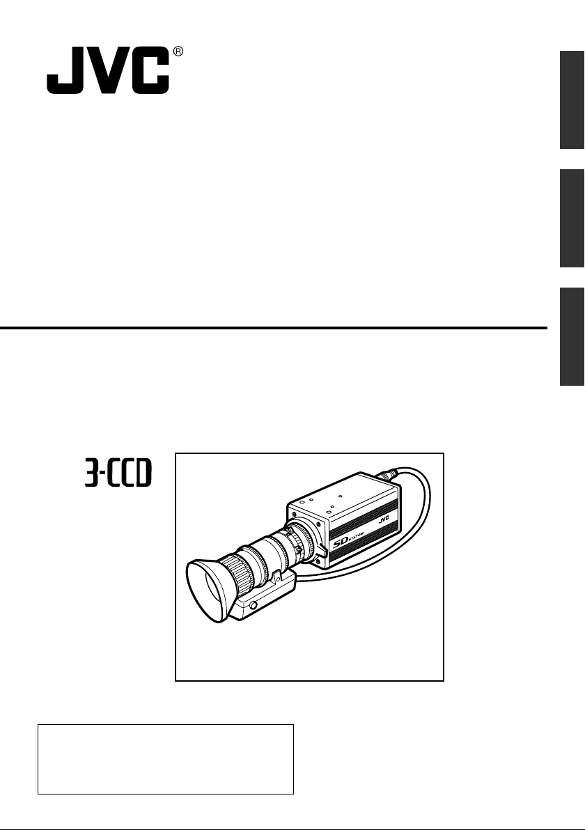
*Illustration with optional lens attachment.
*Illustration mit montiertem optionalem Objektiv.
*Illustration avec objectif optionnel.
Thank you for purchasing this JVC product.
Before operating this unit, please read the
instructions carefully to ensure the best
possible performance.
LWT0164-001A
Page 2

Supplement
This equipment is in conformity with the provisions and protection requirements of the
corresponding European Directives. This equipment is designed for professional video appliances and can be used in the following environments:
5
Residential (including both of the location type class 1 and 2 found in IEC 1000-2-5)
5
Commercial and light industrial (including, for example, theatres)
5
Urban outdoors (based on the definition of location type class 6 in IEC 1000-2-5)
This apparatus is designed for rack mounting or is used close to other apparatus.
In order to keep the best performance and furthermore for electromagnetic compatibility
we recommend to use cables not exceeding the following lengths:
Port Cable Length
LENS Exclusive Cable 0.4 meters
VIDEO OUT Coaxial Cable 5 meters
GENLOCK IN Coaxial Cable 5 meters
REMOTE Exclusive Cable 5 meters
DC IN Exclusive Cable 2 meters
Caution:
5 Where there are strong electromagnetic waves or magnetism, for example near a radio or TV
transmitter, transformer, motor, etc., the picture and sound may be disturbed. In such a case,
please keep the apparatus away from the sources of the disturbance.
E-2
Page 3

SAFETY PRECAUTIONS
WARNING:
TO REDUCE THE RISK OF FIRE OR
ELECTRIC SHOCK, DO NOT EXPOSE
THIS APPLIANCE TO RAIN OR
MOISTURE.
This unit should be used with 12 V DC
only.
CAUTION:
To prevent electric shocks and fire
hazards, do NOT use any other power
source.
Note:
The rating plate (serial number plate) is on
bottom cabinet.
CAUTION
To prevent electric shock, do not open the
cabinet. No user serviceable parts inside. Refer
servicing to qualified service personnel.
English
E-3
Page 4

Thank you for purchasing this product.
These instructions are for KY-F560E.
Contents
1. Getting Started
Features ............................................................................................................................................... 6
Points to Note During Use .................................................................................................................... 7
Part Names and Functions ................................................................................................................... 8
Description of Terminals ..................................................................................................................... 11
2. Preparation Before Shooting
Basic System ...................................................................................................................................... 12
Applied System ................................................................................................................................... 13
Mounting the Lens .............................................................................................................................. 14
Connecting the Power Supply ............................................................................................................ 15
Mounting the Camera ......................................................................................................................... 16
Precautions to Prevent Camera From Falling .................................................................................... 17
3. Setting and Adjustment During Shooting
External Monitor Adjustment .............................................................................................................. 18
Back Focus Adjustment ...................................................................................................................... 19
White Balance Adjustment ................................................................................................................. 20
White Shading Adjustment ................................................................................................................. 22
4. Various Modes of Shooting
Shooting the Computer Monitor .......................................................................................................... 24
Output of Negative Image ................................................................................................................... 25
White Spot Correction ........................................................................................................................ 26
E-4
Page 5

5. Setting Via the Menu Screen
Flow of Menu Screens ........................................................................................................................ 28
Setting Procedures ............................................................................................................................. 30
“EXPOSURE” Screen ......................................................................................................................... 31
“ADVANCED EXPOSURE” Screen .................................................................................................... 33
“WHITE BALANCE” Screen................................................................................................................ 34
“PROCESS (1/2)” Screen ................................................................................................................... 36
“PROCESS (2/2)” Screen ................................................................................................................... 38
“MATRIX ADJUST” Screen ................................................................................................................ 40
“SYSTEM” Screen .............................................................................................................................. 41
“FILE MANAGE” Screen ..................................................................................................................... 42
6. Others
Connecting the Remote Control Unit ..................................................................................................44
Connecting Optional Devices ............................................................................................................. 46
Specifications ..................................................................................................................................... 47
English
Notations and Symbols Used in This Manual
Caution
Note
☞
All product names in this manual are trademarks or registered trademarks of their respective companies.
Marks such as ™, ® and © are not used in this manual.
Precautions during operation are stated.
Restrictions of functions and specifications are stated for reference purposes.
Indicates the page and item to refer to.
E-5
Page 6

1.Getting Started
Features
● Supersensitive and high-performance camera that realizes a horizontal resolution of 850 lines and F13/
2000 lx via three and a half inch CCD and 12-bit DSP processing.
Enables camera control and hence offers a wide range of uses via use of cameras for high resolution
monitoring, relay, data transmission, weddings and conventions with a swivel base.
● Miniature Camera that Employs Bayonet Mount
Employment of bayonet mount and 1/2-inch colour separation optics, and compact design through highdensity mounting of the newly developed IC.
● Automatic Switching between Internal Sync/External Sync
Employs automatic switching between internal/external sync, which is useful for switching between multiple cameras or system upgrade via connection with other devices.
● EBU-compliant Built-in Colour Bars Generator
Colour monitor can be adjusted with ease with the use of EBU colour bars.
● Variable Scan Shutter
Eliminates flicker when shooting screen pictures other than PAL, such as computer screens.
● Equipped with White Shading Function
Corrects colour shading triggered by optical characteristics.
● Black Stretch/Black Compress Feature
Stretches or compresses the gain of the dark section in an image to adjust the tone of that section.
● Negative
Used for special purposes such as shooting using films.
● AE (Automatic Exposure)
5 selectable modes in the AE area that are useful when there is a difference in brightness between the
object and its surroundings.
In addition, exposure settings can also be performed according to shooting conditions via selection of AE
level adjustment or photometry detection.
● Built-in White Spot Correction Feature
● Equipped with Remote Terminal
Supports remote control via the remote control unit (sold separately).
● Equipped with Expansion Slot
System upgrade via connection of optional devices (sold separately) is possible.
E-6
Page 7

Points to Note During Use
• For important shootings, perform trials in advance to ensure that they are properly recorded.
• We will not compensate for contents lost due to the malfunction of this unit.
Characteristic CCD Phenomena
• Smear and Blooming
When shooting a bright light source, the CCD may induce white streaks (smear) in the vertical direction of the light source. When the light source is extremely bright, light of the surroundings may
expand (blooming).
• Aliasing
Note that a jagged effect may occur when shooting striped patterns or lines.
• White spot
Operating this unit under a high temperature may give rise to white spots in the image. Ensure to use
this unit within the specified range (–5˚C to 40˚C).
This unit comes with the white spot correction feature that helps to reduce this phenomenon.
☞ Page 26
Precautions During Handling
• Strong Electromagnetic Waves or Magnetism
When placed near radios or TV transmitters, or transformers and monitors that emit strong magnetism, noise or colour change may occur in the image. Ensure that this unit is kept away from the above
during use.
• Compatible Lens ☞ Page 14 ‘Mounting the Lens’
Lens mount of this unit makes use of bayonet mount and there are restrictions on the type of lens to
be used.
Pay attention to their performance and dimensions when lenses other than those specified are used.
• Cleaning the Body of this Unit (Turn off the power before cleaning.)
Wipe using a soft cloth.
Do not wipe with thinner or benzene. These may corrode or tarnish the surface.
When it is extremely dirty, wipe using a neutral detergent diluted with water, follow by wiping with a
dry cloth.
• When not in use, turn off the power of the system to reduce power consumption.
• Do not mount unit at locations that emit radiation, X-rays or corrosive gases.
English
E-7
Page 8
1. Getting Started (continued)
Part Names and Functions
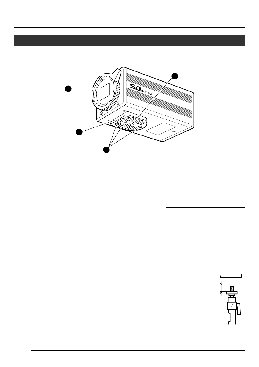
Front / Bottom
1
2
3
COLO
R VIDEO CAM
4
ERA
KY-F560
1 Lens Mounting Ring/Lens Lock
Lever
When dismounting the lens, do so by holding
the lens and turning the lens lock lever in the
anti-clockwise direction.
When mounting the lens, check that the guide
pins of the lens are aligned, followed by turning
the lens lock lever in the clockwise direction to
fasten.
☞ Page 14 ‘Mounting the Lens’
2 Camera Mounting Bracket
This is attached to the bottom face of the camera when supplied. Mount it to the top surface
according to the conditions of use. Mount the
fastening screws for the camera mounting
bracket 3 to the screw holes on the top surface.
☞ Page 16 ‘Mounting the Camera’
E-8
3 Fastening Screws for Camera
Mounting Bracket
(M2.6 x 6 mm, 3 pcs)
Caution
Make sure to use screws that are supplied with
this unit.
Use of screws that are 6 mm or longer in length
may give rise to malfunction of the unit.
4 Camera Mounting Screw Holes
(1/4-20UNC)
Use when mounting this unit
to fixer or swivel bases.
(Use screws that are 7 mm
or shorter in length.)
7mm
and
below
Page 9
Part Names and Functions (continued)
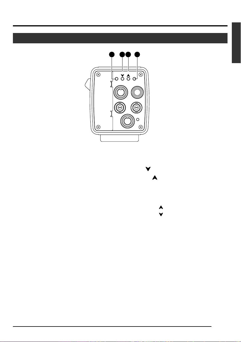
Back
5 [MENU] Menu Button
Press this button for 1-2 seconds. Menu screen
will be output from the [VIDEO OUT] terminal.
Press the button for 1-2 seconds again to clear
the menu screen.
☞ Page 30 ‘Setting Procedures’
6 [SET] Set Button
When the menu screen is displayed, use it to
select a submenu or to confirm a selected item
or set value.
☞ Page 30 ‘Setting Procedures’
5 87 6
AW
BARS
MENU
GENLOCK IN
DC IN
SEE INSTRUCTION MANUAL
REMOTE
SET
LENS
VIDEO OUT
POWER
7 [AW/ ] Auto White/Down Button
8 [BARS/ ] Colour Bars/Up Button
When menu screen is displayed
Press these buttons to move between selection items on the menu screen.
Use the [ ] button to move upwards.
Use the [ ] button to move downwards.
Used for altering the set values when an item
is being selected.
When the menu screen is off
● Press the [AW] button to adjust the white
balance.
☞ Page 20 ‘White Balance Adjustment’
● Press the [BARS] button to switch between the colour bars output and camera
image output.
● Use this button when adjusting the monitor or when recording colour bars signal.
☞ Page 18 ‘External Monitor Adjustment’
English
E-9
Page 10
1. Getting Started (continued)
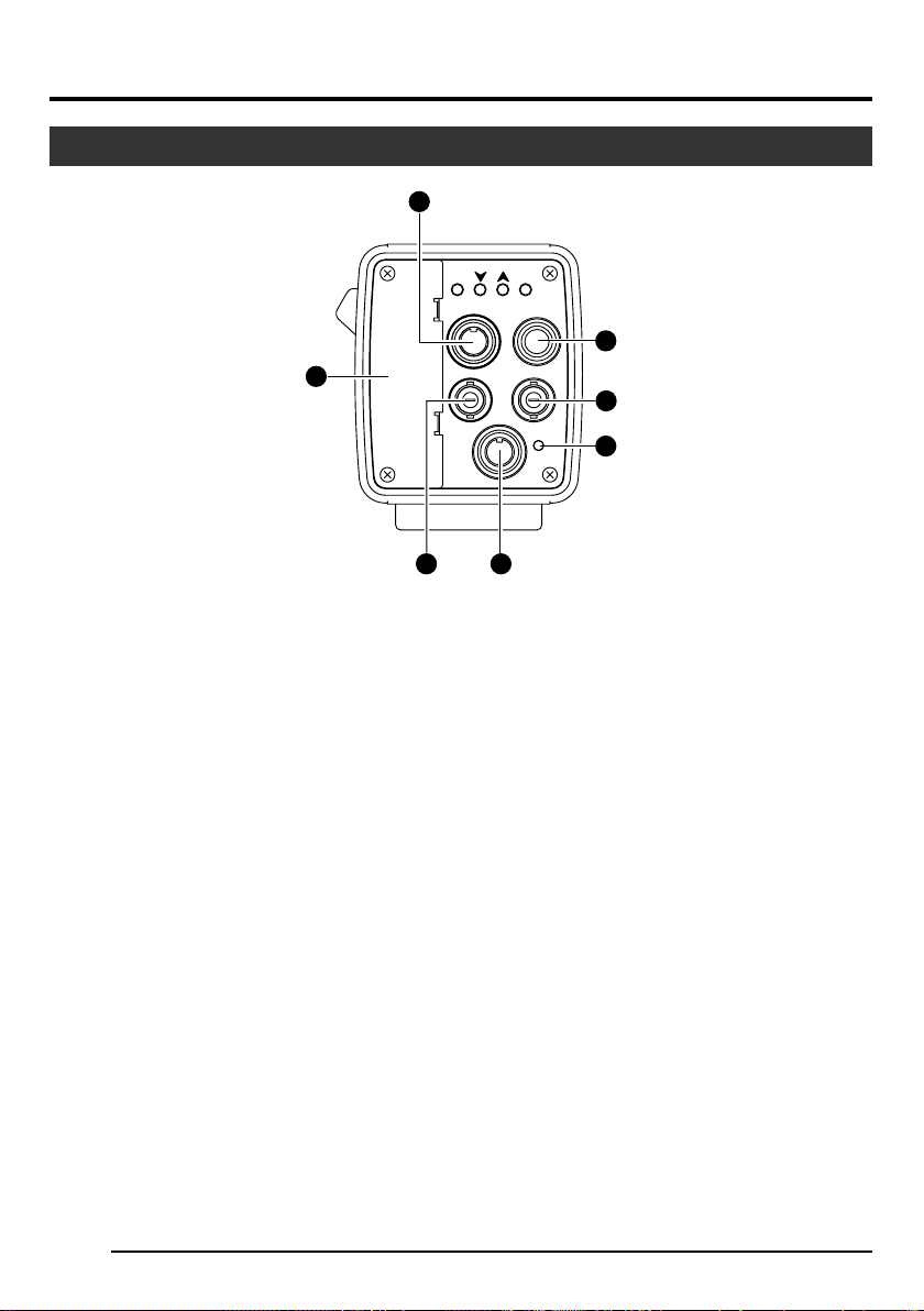
Part Names and Functions (continued)
Back
15
9
14
9 [REMOTE] Remote Terminal
(Mini DIN 6 Pin, Female)
Terminal for connection to remote control unit
(RM-LP55 or RM-LP57, both sold separately).
☞ Page 11 ‘Description of Terminals’
☞ Page 44 ‘Connecting the Remote Control
Unit’
0 [LENS] Lens Connection Terminal
Connect the lens cable.
☞ Page 11 ‘Description of Terminals’
☞ Page 14 ‘Mounting the Lens’
! [VIDEO OUT] Video Signal Output
Terminal
Output terminal for composite video signals.
Connect to video input terminals such as monitors or switchers.
@ [POWER] Power Indicator Light
Lights up when power is supplied to this unit.
AW
BARS
MENU
GENLOCK IN
DC IN
SEE INSTRUCTION MANUAL
REMOTE
13
SET
LENS
VIDEO OUT
POWER
10
11
12
# [DC IN] Power Input Terminal
(Mini DIN 8 Pin, Female)
Power of this unit (DC 12 V) is supplied through
this terminal.
Use an AC adaptor (AA-P700) for the power
supply.
☞ Page 11 ‘Description of Terminals’
☞ Page 15 ‘Connecting the Power Supply’
$
[GENLOCK IN] External Sync Signal
Input Terminal
Reference signal input terminal for synchronization with this unit.
Inputs composite video signals or black burst
signals.
% Slot Cover for Option Cards
Remove the cover to install the option card.
☞ Page 46 ‘Connecting Optional Devices’
Please consult your JVC-authorized dealer on
optional devices.
E-10
Page 11
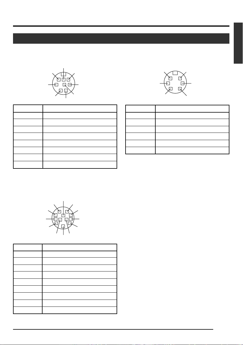
Description of Terminals
Power Input Terminal (Mini DIN 8 Pin,
Female)
Pin No.
1
2
3
4
5
6
7
8
7
8
5
2
NC
GND
NC
NC
GND
+ 12 V Input
NC
+ 12 V Input
6
3
4
1
Signal
Lens Connection Terminal (Metal 12
Pin, Female)
10
9
8
7
6
12
1
2
3
4
11
5
Remote Terminal (Mini DIN 6 Pin,
Female)
6
4
2
Pin No.
1
2
3
4
5
6
GND
OPERATE (L:ON)
GND
SID2(TX)
SID1(RX)
+ 9 V Output
Notes
• Please consult your JVC-authorized dealer on
connection of remote terminals.
• Ensure to use cables that are shielded.
5
3
1
Signal
English
Pin No.
1
2
3
4
5
6
7
8
9~12
Signal
LENS RET
NC
GND
LENS AUTO
IRIS CONTROL
+ 12 V Output
IRIS POSITION
IRIS A/R
NC
E-11
Page 12
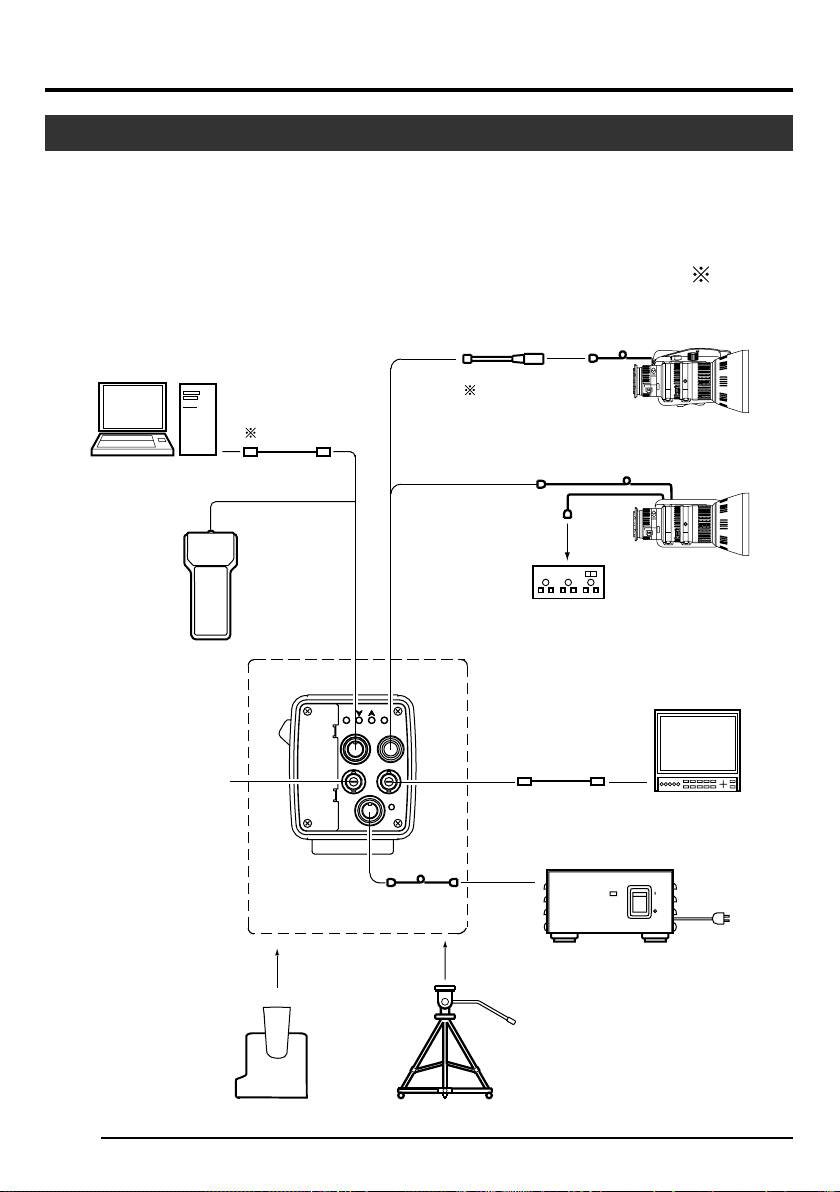
2. Preparation Before Shooting
Basic System
The diagram below illustrates connection of a basic system.
When connecting
• Perform this when the unit is off.
• Read the instruction manual of the unit before performing it.
• Consult your JVC-authorized dealer on details of the equipment in use of cables with the mark.
PC
RS-232C PC
CAMERA CONTROL
REMOTE
CONTROL UNIT
RM-LP55
RM-LP57
Sync Signals
(Composite Video
Signals or Black
Burst Signals)
VC-P893
AW
BARS
MENU
SET
REMOTE
LENS
VIDEO OUT
GENLOCK IN
DC IN
POWER
SEE INSTRUCTION MANUAL
KY-F560
POWER CORD (2 m)
STANDARD PACKAGE
LENS CABLE
ECE-R22
8P8P
LENS REMOTE
CONTROL
(FUJINON)
RMD-10
RMD-20
BNC CABLE
MD
CONTROL
CABLE
(CANON)
TCR-101F
POWER
MACRO
ZOOM LENS
S17 x 6.6BRM (FUJINON)
YH16 x 7K12U (CANON)
MACRO
MD ZOOM LENS
S16 x 7.3BMD (FUJINON)
YH16 x 7BKTS (CANON)
MONITOR
AC ADAPTER AA-P700
ON
OFF
AC120 V
E-12
PAN
AND
TILT
UNIT
TRIPOD
TP-P300
DOLLY
TP-P205
AC POWER ADAPTER
AA-P700
Page 13
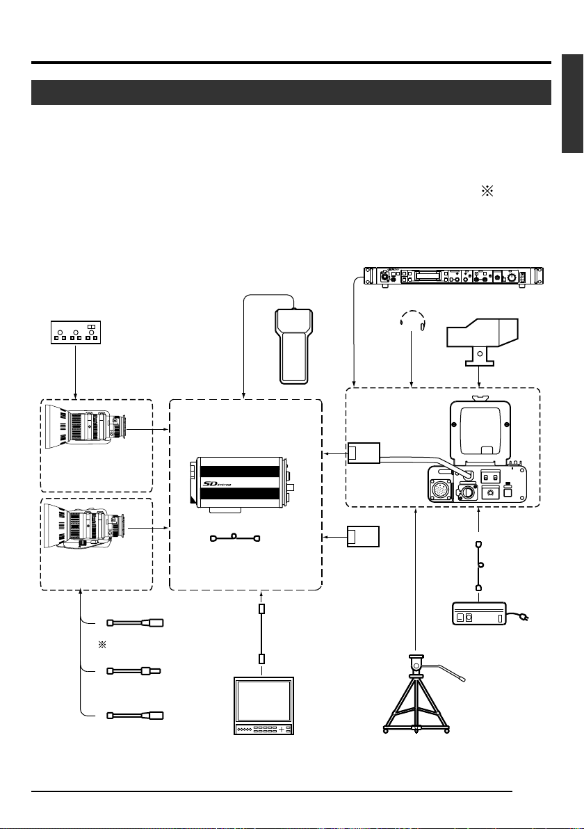
Applied System
The diagram below illustrates connection of an applied system.
When connecting
• Perform this when the unit is off.
• Read the instruction manual of the unit before performing it.
• Consult your JVC-authorized dealer on details of the equipment in use of cables with the mark.
CAMERA REMOTE CONTROL UNIT
CALLTALLY
FULL AUTO F1
SHUTTER
BARS
F2
GAIN
INTERCOM
LEVEL
HEAD SET
STUDIO KIT
KA-F5602
KA-F5603
SDI OUTPUT
CARD
KA-F5601
RM-P210
MENU/SHUTTER GAIN
F3
SHUTTER
PUSH-ON
MENU
F4
DOWN UP
PUSH
REMOTE CONTROL UNIT RM-P210
WHITE MASTER BLACK
PAINT AUTO
STEP
W.BAL
HIGH
B
VARIABLE
MID
A
PUSH-ON
BR
PRESET
LOW
DOWN UP
VIEWFINDER
VF-P400
INCOM MIC
ON
CARBON
OFF
DYNAMIC
INTERCOM
INCOM LEVEL
MAXMIN
4P
VC-710 (5 m
4P
IRIS
AUTO
MANU
CLOSE OPEN
VF
CALL
LENS REMOTE CONTROL
(FUJINON)
RMD-10
RMD-20
MACRO
MD ZOOM LENS
S16 x 7.3BMD (FUJINON)
YH16 x 7BKTS (CANON)
MACRO
ZOOM LENS
S17 x 6.6BRM (FUJINON)
YH16 x 7K12U (CANON)
(CANON)
TCR-101F
COLOUR VIDEO CAMERA
POWER CORD (2 m)
KY-F560
STANDARD PACKAGE
REMOTE
CONTROL UNIT
RM-LP55
RM-LP57
COLOR VIDEO CAMERA KY-F560
8P8P
English
POWER
I
O
)
ECE-R22
LENS CABLE
ZOOM SERVO UNIT
HZ-ZS13B
FOCUS MANUAL UNIT
HZ-FM13 (FUJINON)
HZ-FM15 (CANON)
BNC CABLE
MONITOR
TRIPOD
TP-P300
DOLLY
TP-P205
AC
AC POWER ADAPTER
AA-P250
E-13
Page 14

2. Preparation Before Shooting (continued)
Mounting the Lens
Follow the procedures below when mounting the auto iris lens.
Refer to the ‘instruction manual’ for the lens and lens remote control as well.
AW
BARS
MENU
Lens
Pin
MACRO
Hole
1.
2.
3.
Lens Cable
Lever for securing the lens
Compatible MD Zoom Lens
S16 x 7.3 BMD (Fujinon)
YH16 x 7 BKTS (Canon)
5.
Control Cable
1.
Loosen by turning the lens lock lever in the anti-clockwise direction.
2.
Mount upon ensuring that the pin and mounting hole of the lens are aligned.
3.
Fasten by turning the lens lock lever in the clockwise direction.
4.
Plug the lens cable into the [LENS] terminal at the back of the unit and ensure that it is locked.
5.
When connecting to the lens remote control, connect the cable (female) for controlling the lens to the
remote control.
Lock (Female)
Lens Remote
REMOTE
GENLOCK IN
DC IN
SEE INSTRUCTION MANUAL
Control
SET
LENS
VIDEO OUT
POWER
Lock (Male)
4.
Compatible Lens
Remote Control
(Fujinon)
RMD-10
RMD-20
(Canon)
TCR-101F
Note
When connecting the manual iris lens or lens remote control to operate the lens iris manually, set the “IRIS
MODE” item to “MANUAL”.
☞ Page 31 ‘ “IRIS MODE” Item on “EXPOSURE” Screen’
Caution
• Perform this when the unit is off.
Connecting with the power on may give rise to malfunction of the unit.
• When removing the lens mount cap, ensure that no foreign substances are inside the mount.
• Lenses are not supplied with this unit. Make sure to use lenses that are compatible with this unit.
E-14
Page 15
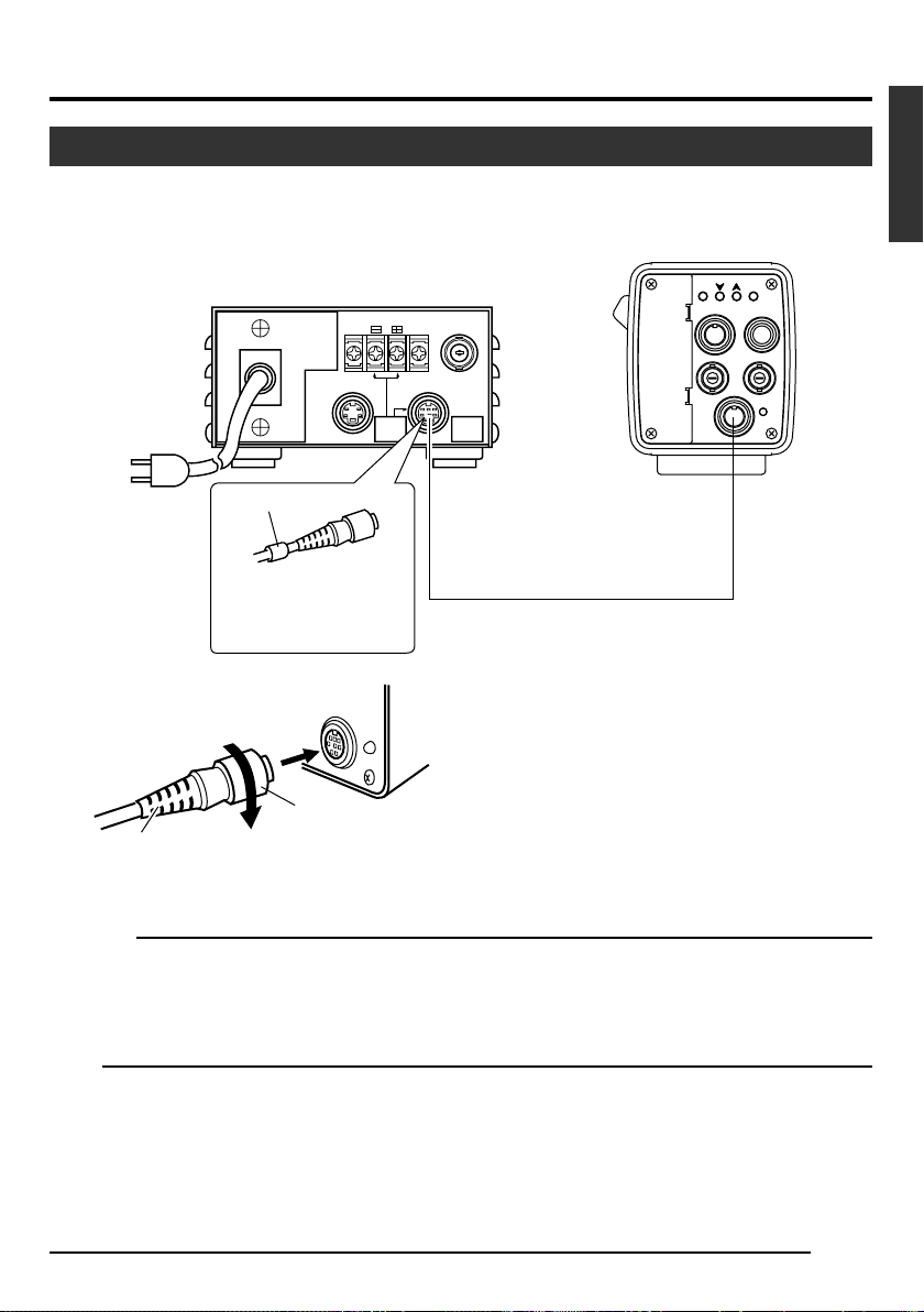
Connecting the Power Supply
Connect the [DC IN] terminal at the back of this unit to the [TO CAMERA] terminal of the AC adaptor (AAP700) using the power cable supplied (2 m).
AW
BARS
MENU
REMOTE
GENLOCK IN
DC IN
SEE INSTRUCTION MANUAL
Terminal
SET
LENS
VIDEO OUT
POWER
[DC IN]
AC 120 V
AA-P700 AC Adaptor
DC 12V=OUTPUT
AC 100V
EITHER
OUTPUT
MAX 1.25A
White Marking
Connect the end with
white marking to the AC
VIDEO OUTPUT
TO CAMERAS(Y/C) OUTPUT
SEE INSTRUCTION
MANUAL
[TO CAMERA] Terminal
Power Cable (2 m)
(accessories)
adaptor.
DC IN
POWER
● Insert plug fully, turn ring and ensure that it is fastened.
Connect the plug in the same way at the AC adaptor's
end.
Ring
Plug
English
Caution
Ensure to make use of AA-P700 for the power supply.
When connecting, ensure that power switch of AA-P700 is turned OFF. Connecting with the power on may
give rise to malfunction of the equipment.
Note
Allow a 10 second interval after switching off the power before turning on again. If the power switch is turned
ON and OFF too soon, malfunctioning such as startup failure may occur.
E-15
Page 16

2. Preparation Before Shooting (continued)
Mounting the Camera
<Mounting Procedures>
Anti-rotation Hole
Screw Hole for Mounting Camera
• To mount this unit, make use of the screw holes
• When mounting this unit, make use of the anti-
Camera Mounting Bracket
<Changing the Camera Mounting Bracket>
Camera Mounting Bracket is mounted to the bottom
surface of the camera when supplied. To mount it to
the top surface, do so by removing the 3 fastening
screws of the camera mounting bracket.
COLOR VIDEO CAMERA
KY-F560
Caution
Make sure to use screws supplied with this unit. Use
of screws that are 6 mm or longer in length may give
rise to malfunction of the unit.
for mounting the camera on the camera mounting
bracket.
rotation hole to prevent it from falling.
E-16
Page 17

Precautions to Prevent Camera From Falling
Safety cable to Prevent
Falling of Equipment
6 mm
English
Camera Head
COLOR VIDEO CAMERA
KY-F560
Caution
● Special attention is required when mounting to the wall or ceiling. Get a
contractor to perform the work and avoid doing it on your own. Unit may
fall off and cause injuries or accidents.
● Mount the unit to a secure place using safety cable to prevent it from falling. To mount, make use of the bracket fastening screw holes on the face
without the camera mounting bracket. (M2.6 x 6 mm)
Pay attention also to the length of the cable.
● Strength of cable to prevent falling of unit shall be at least 10 times greater
than the total mass of the camera and lens.
E-17
Page 18

3. Setting and Adjustment During Shooting
External Monitor Adjustment
Display the built-in colour bars signal at the camera on the monitor to perform colour/contrast/brightness
adjustment.
1.
2.
[BARS] button
AW
MENU
REMOTE
GENLOCK IN
DC IN
SEE INSTRUCTION MANUAL
BARS
SET
LENS
VIDEO OUT
POWER
1.
Connect the colour video monitor to the [VIDEO OUT] of this
unit.
2.
Press the [BARS] button to output the colour bars signal (EBUcompliant colour bars).
3.
With the colour bars displayed, turn [BLUE CHECK] at the monitor to ON.
Screen turns into a monochrome of blue and colour bars appear as blue stripes.
4.
Turn the [CHROMA] adjustment knob on the monitor and adjust colour bars 1 and 7 to the same brightness level.
5.
With [BLUE CHECK] in the ON mode, turn the [PHASE] adjustment knob on the monitor to adjust colour bars 3 and 5 to
the same brightness level.
6.
If brightness of colour bars 1 and 7 vary upon [PHASE] adjustment, repeat chroma adjustment as in step 4..
7.
Turn [BLUE CHECK] at the monitor to OFF and return to the
normal screen (R, G and B are all displayed).
3.~7.
White
Yellow
Cyan
Green
Magenta
Red
Blue
12345678
E-18
Black
Page 19

Back Focus Adjustment
When the lens is mounted for the first time, adjust back focus of the lens if the focus for telephoto/wide angle
during zoom is not aligned.
• Check whether the macro ring has been moved before adjustment. If so, restore the macro fixing knob
to the original position.
• Place the camera at a distance of 3 m or further away from the object.
The best will be to use the Siemens Star Chart as the object.
4., 6.
3. 5.
RET
WT
M
A
1.
MACRO
Zoom Lens
1.
Set iris mode switch of lens to M (manual).
2.
Set zoom mode switch to M (manual).
3.
Turn to open the iris ring.
Adjust illumination to obtain the proper image level.
4.
Turn the zoom lever to adjust lens to the greatest telephoto
position.
5.
Turn the focus ring and align focus on the object.
6.
Adjust lens to the widest angle position.
7.
Loosen the fastening screw for the back focus ring.
8.
Focus on the same object and select a position for which focus
is best aligned, followed by fastening the back focus ring.
9.
Repeat steps
for both telephoto and wide angle.
10.
Tighten fastening screw for back focus ring securely.
4. ~ 8.
for about three times until focus is aligned
English
2. 7., 8.,
10.
Siemens Star Chart (Object)
Power Zoom Lens
There is no manual mode for power zoom lens. Connect the
lens remote control.
Adjustment Procedures
To adjust, follow steps
For more details, please refer to the instruction manual for the
lens or lens remote control.
3. ~10.
above.
E-19
Page 20

MENU
AW
BARS
SET
LENS
REMOTE
GENLOCK IN
VIDEO OUT
3. Setting and Adjustment During Shooting (continued)
White Balance Adjustment
Colour of light (colour temperature) may vary with light sources. When light source for illumination of object
is changed, adjust white balance (AUTO WHITE) again. Do not place strong reflectors such as metals near
the object. This may cause error in achieving white balance.
[ /AW]
[ ]
[MENU]
Item
-- ---CE-WHI TE BALA N
WH I T E
LEVEL(R)
LEVEL(B)
SHADING
LEVEL(R)
LEVEL(G )
LEVEL(B)
PAGE BACK
CEBALAN
[SET]
Set Value
AUTO1
0
0
TPRESE
- - - - - -
- - - - - -
- - - - - -
“WHITE BALANCE” Screen
Auto White Operation Area
WHIAUTO E1T
RATOPE ION
Auto White Operation
Activated
White balance adjustment includes Auto White, Full-time Auto White
(FAW), manual and preset.
Setting procedures for Auto White
(“AUTO1”,“AUTO2”)
1.
Press the [MENU] button for 1-2 seconds.
The “MENU” screen will be displayed.
2.
Use the [ / ] buttons to select “WHITE BALANCE..”, then
press the [SET] button.
The “WHITE BALANCE” screen will be displayed.
3.
Use the [ / ] buttons to select “WHITE BALANCE”, then press
the [SET] button.
The set value displayed will start to blink.
4.
Use the [ / ] buttons to select “AUTO1” or “AUTO2”, then
press the [SET] button.
5.
Press the [MENU] button for 1-2 seconds.
The normal screen will be displayed.
Note
Upon returning to the normal screen, place a white object with
the same illumination conditions as the object, zoom in to the
white portion at the center of the screen (above 80% within the
area).
6.
Press the [AW](Auto White) button.
● When auto white is activated, the auto white operation area
and “AUTO WHITE1 OPERATION” are displayed on the
monitor.
● When white balance is achieved “AUTO WHITE1 OK” will
be displayed for about 3 seconds before returning to the
normal screen.
WHAUTO TIE1
OK
Auto White Operation Ends
E-20
Page 21

White Balance Adjustment (continued)
O WH AUT ITE
1
G:OBNJ E CT
Object Error
O WH AUT ITE
1
R:LOERRO W L I T GH
Insufficient Illumination
O WH AUT ITE
1
R:OVERROE R L HT IG
Excessive Illumination
Error Display
When auto white adjustment is not correctly ended, the following
message will be displayed for about 3 seconds.
● “NG:OBJECT” (Object Error)
Displayed when there is little white colour in the object or when
colour temperature is not appropriate.
Change to a white object and perform procedures again to
achieve white balance.
● “ERROR:LOW LIGHT” (Insufficient Illumination)
Displayed when illumination is too dark. Brighten the illumination and perform procedures again to achieve white balance.
● “ERROR:OVER LIGHT” (Excessive Illumination)
Displayed when illumination is too bright. Darken the illumination and perform procedures again to achieve white balance.
English
Full-time Auto White (FAW) Function
Automatic adjustment of white balance according to different illumination conditions.
This mode is useful when there is no time to readjust white balance or when camera is frequently moved to
locations with different illumination conditions.
● However, white balance cannot be properly achieved in cases that are beyond the adjustable range of the
full-time auto white function, such as when there is only one colour or little white colour in the object.
● Precision of FAW deteriorates when compared with manual white balance.
● When power is turned on in the FAW mode, it takes about 10 seconds for the FAW automatic adjustment
to end.
E-21
Page 22

MENU
AW
BARS
SET
LENS
REMOTE
GENLOCK IN
VIDEO OUT
3. Setting and Adjustment During Shooting (continued)
White Shading Adjustment
There are cases when white balance is achieved for the center of the screen but not for the upper and lower
ends, hence causing other colours to appear with green or magenta. This is brought about by the lens
characteristics. The process of rectifying this is known as white shading.
[MENU]
1.
--- MENU ---
EXPOSURE . .
WH I T E B ALANCE. .
PROCE SS . .
SYSTEM. .
FILE M
ANAGE
EX I T
“MENU” Screen
2.
-- ---CE-WHI TE BALA N
WH I T E
LEVEL(R)
LEVEL(B)
SHADING
LEVEL(R)
LEVEL(G )
LEVEL(B)
BACKPAGE
[ ]
..
CEBALAN
[ ]
[SET]
0
0
- - - - - -
- - - - - -
- - - - - -
Perform the following setting upon adjusting white balance.
☞ Page 20
1.
Press the [MENU] button for 1-2 seconds.
The “MENU” screen will be displayed.
2.
Use the [ / ] buttons to select “WHITE BALANCE..”, then
press the [SET] button.
The “WHITE BALANCE” screen will be displayed.
3.
Use the [ / ] buttons to select “SHADING”, then press the
[SET] button.
The set value starts blinking and adjustment is possible.
4.
Use the [ / ] buttons to set value to “MANUAL”, then press
the [SET] button.
LMANUA
TPRESE
“WHITE BALANCE” Screen
3. 4.
E-22
-- ---CE-WHI TE BALA N
WH I T E
LEVEL(R)
LEVEL(B)
SHADING
LEVEL(R)
LEVEL(G )
LEVEL(B)
CEBALAN
BACKPAGE
LMANUA
0
0
LMANUA
0
0
0
Blinking
Page 23

White Shading Adjustment (continued)
5. 6.
-- ---CE-WHI TE BALA N
WH I T E
LEVEL(R)
LEVEL(B)
SHADING
LEVEL(R)
LEVEL(G )
LEVEL(B)
7.
-- ---CE-WHI TE BALA N
WH I T E
LEVEL(R)
LEVEL(B)
SHADING
LEVEL(R)
LEVEL(G )
LEVEL(B)
Blinking
5.
Use the [ / ] buttons to select items for “LEVEL(R)”,
English
“LEVEL(G)” and “LEVEL(B)”, then press the [SET] button.
CEBALAN
BACKPAGE
LMANUA
0
0
LMANUA
0
0
0
The set value starts blinking and adjustment is possible.
6.
Refer to the monitor to adjust values for “LEVEL(R)”,
“LEVEL(G)” and “LEVEL(B)” using the [ / ] buttons.
As each of the set values get bigger, the colour at the lower
end of the screen lightens while that at the upper end darkens.
{Variable Values: –128 - +127}
7.
Upon changing the set values, press the [SET] button to record
them in the memory of this unit.
8.
Press the [MENU] button for 1-2 seconds.
CEBALAN
BACKPAGE
LMANUA
0
0
LMANUA
10
0
0
The normal screen will be displayed.
9.
Upon completing white shading adjustment, perform white balance adjustment again.
☞ Page 20 ‘White Balance Adjustment’
E-23
Page 24

4. Various Modes of Shooting
Shooting the Computer Monitor
When shooting images of computer monitors or displays, horizontal bands will appear on the screen. To
eliminate the bands, it will be necessary to align the shutter speed with the scanning frequency of the
monitor.
1.
Press the [MENU] button for 1-2 seconds.
The “MENU” screen will be displayed.
2.
Use the [ / ] buttons to select “EXPOSURE..”, then press
the [SET] button.
3.
Use the [ / ] buttons to select “SHUTTER”, then press the
[SET] button.
The set value starts blinking and adjustment is possible.
4.
Use the [ / ] buttons to set value to “V.SCAN”, then press
the [SET] button.
5.
Use the [ / ] buttons to select “LEVEL”, then press the [SET]
button.
6.
Use the [ / ] buttons to adjust the shutter speed. Pay attention to the screen
If black bands are visible : use the [ ] button to lower the shut-
ter speed
If white bands are visible : use the [ ] button to increase the
shutter speed
7.
When bands are decreased to the minimum, press the [SET]
button. This will be recorded in the memory of the unit.
8.
Press the [MENU] button for 1-2 seconds.
The normal screen will be displayed.
Computer Monitor
3. 4.
--- ---EXPOSURE
IRIS MODE
MA LAUN
GA I N
LEVEL
ELEV L
SHUTTER
LEVEL
EXPOSURE
ADVANCED
BACKPAGE
“EXPOSURE” Screen
..
AUTO
- - - - - -
STE P
0dB
STEP
NO LAMR
Band
5. 6.
--- ---EXPOSURE
IRIS MODE AU
MA LAUN
ELEV L
SHUTTER
LEVEL
ADVANCED
BACKPAGE
LEVEL
EXPOSURE
GA I N
Note
Vertical scanning frequency may vary with computer types and there are cases when bands may not be fully
eliminated. In addition, frequency may also differ depending on the software used.
E-24
- - - - - -
STEP
V. SCAN
1/50s
..
TO
0dB
Page 25

Output of Negative Image
MENU
AW
BARS
SET
LENS
REMOTE
GENLOCK IN
VIDEO OUT
It is possible to convert video signals output from the [VIDEO OUT] terminal of this unit into negative images.
[MENU]
[ ]
[ ]
[SET]
1.
Press the [MENU] button for 1-2 seconds.
The “MENU” screen will be displayed.
2.
Use the [ / ] buttons to select “SYSTEM..”, then press the
[SET] button.
The “SYSTEM” screen will be displayed.
3.
Use the [ / ] buttons to select “NEGATIVE”, then press the
[SET] button.
The set value starts blinking and adjustment is possible.
4.
Use the [ / ] buttons to set value to “ON”, then press the
2. 3.
ASPECT RA
NEG
H PHA0SE
SC COARSE
SC FINE
PAGE
--- ---SYSTEM
AOFFTIVE
BACK
TIO
PENIPXEL COM
4:3
CANCEL
0
0
Blinking
[SET] button.
This will be recorded in the memory of the this unit.
Ouput image will be converted to negative images.
5.
Press the [MENU] button for 1-2 seconds.
The normal screen will be displayed.
“SYSTEM” Screen
4. 5.
--- ---SYSTEM
ASPECT RA
NEG
H PHA0SE
SC COARSE
SC FINE
PAGE
AONTIVE
BACK
TIO
PENIPXEL COM
4:3
CANCEL
0
0
English
“SYSTEM” Screen
E-25
Page 26

4. Various Modes of Shooting (continued)
MENU
AW
BARS
SET
LENS
REMOTE
GENLOCK IN
VIDEO OUT
White Spot Correction
As a peculiar common characteristic of CCD, white spots may appear on the screen when operated under
high temperature.
This unit comes with a white spot correction feature to reduce this phenomenon.
How To Use
Detection of White Spots
The quantity and size of white spots differ with the temperature and shutter speed during use. Before
using the white spot correction feature, it will thus be necessary to detect the position of the white spots
under the conditions of use.
[MENU]
2. 3.
--- ---SYSTEM
ASPECT RA
NEG
AT IVE
H PHA0SE
SC COARSE
SC FINE
PAGE
BACK
“SYSTEM” Screen
4. 5.
--- ---SYSTEM
ASPECT RA
NEG
AT IVE
H PHA0SE
SC COARSE
SC FINE
PAGE
BACK
TIO
PENIPXEL COM
TIO
PENIPXEL COM
[ ]
[ ]
4:3
FOF
CANCEL
0
0
4:3
FOF
EXECUTE
0
0
[SET]
Blinking
Blinking
Preparation
• Set the conditions of use (ambient temperature, shutter speed,
etc.) in this unit.
• Turn on the power of the camera and leave it on for at least 2
hours.
• Close the lens iris to ensure that no light enters the CCD.
Operation
1.
Press the [MENU] button for 1-2 seconds.
The “MENU” screen will be displayed.
2.
Use the [ / ] buttons to select “SYSTEM..”, then press the
[SET] button.
The “SYSTEM” screen will be displayed.
3.
Use the [ / ] buttons to select “PIXEL COMPEN”, then press
the [SET] button.
The “CANCEL” value starts blinking and adjustment is possible.
4.
Use the [ / ] buttons to select “EXECUTE” and press the
[SET] button to start the white spot detection.
Detection process may take a few minutes to complete.
5.
Upon completing detection,“Detection Completed” screen will
be displayed.
6.
Turn on the power again.
Allow a 10 seconds interval after switching off the power before turning on again.
When power is turned on, white spots will be corrected.
“SYSTEM” Screen
E-26
Page 27

White Spot Correction (continued)
PIXEL COMPEN
OK
TURN POWER OFF
AND ON AGAIN
PIXEL COMPEN
ERROR : COUNT OVER
TURN POWER OFF
AND ON AGAIN
PIXEL COMPEN
ERROR : LENS NOT CLOSED?
PIXEL COMPEN
ERROR : COUNT OVER
TURN POWER OFF
AND ON AGAIN
White Spot Correction Messages
Detecting Screen
PIXEL COMPEN
EXECUTING
PIXEL COMPEN
ERROR : LENS NOT CLOSED?
Detection Error Screen
Detection Completed Screen
Notes
• The white spot correction feature of this unit does not correct all white spots. Detection and correction of
white spots by this unit is performed under the following conditions. White
spot correction will not be performed under conditions beyond those
stated. In cases where conditions are fulfilled, correction may not be successfully performed depending on the nature of the white spots.
In such case, perform the detection again until white spots are detected.
Consult your JVC authorized dealer if white spots cannot be corrected.
Quantity of Detection/Correction: 32 or less
• The screen on the right may be displayed during detection of white spots
in cases when light enters the CCD during detection or depending on the
condition of white spots. In this case, check if there is light entering the
CCD. If the screen is displayed despite that no light enters the CCD,
increase the shutter speed by 1 step and perform detection again.
• During white spot correction, pixel data is obtained via interpolation of
pixel information from the surroundings. Thus data may not be accurate
for fine images.
• Results of white spot detection will be stored until the next detection is
performed.
• During white spot detection, operation via the remote control will be disabled.
E-27
English
Page 28

5. Setting Via the Menu Screen
Flow of Menu Screens
The menu screen is made up of multiple layers of menu screens as illustrated in the diagram below.
Select the menu screen for setting at the MAIN MENU screen according to function and usage, and perform
setting accordingly.
Cursor
EXPOSURE . .
WH I T E B ALANCE. .
PROCESS . .
SYSTEM . .
FILE M
EX I T
MAIN MENU
--- MENU ---
..
ANAGE
Normal Screen
--- ---EXPOSURE
IRIS MODE
MA LAUN
LEVEL
GA I N
ELEV L
SHUTTER
LEVEL
EXPOSURE
ADVANCED
BACKPAGE
-- ---CE-WHI TE BALA N
LEVEL(R)
LEVEL( B)
SHADING
LEVEL(R)
LEVEL(G )
LEVEL( B)
PAGE BACK
---)PROCESS( 1 / 2
SAMTERBL
DETA LI
LEVEL
LAACEN
V/H B
FR
EEUNQYC
RESOLUT I ON
V.
KNEE
IP
HWITECL
LEVEL
NEXT PAGE . .
PAGE BACK
--- ---SYSTEM
ASPECT RA
NEG
AT IVE
H PHA0SE
SC COARSE
SC F INE
PAGE
BACK
AUTO
- - - - - -
STE P
STEP
NO LAMR
..
CEBALANWH I T E
AUTO1
0
0
PRESET
- - - - - -
- - - - - -
- - - - - -
ACK 0
TIO
4:3
CANCEL
PENIPXEL COM
0
0
0d
NO
0
0
LOW
ORNALM
081%
UTAO
- - - - - -
FOF
☞ Page 31
B
☞ Page 34
☞ Page 36
☞ Page 41
E-28
--- ---
FILE MA
LOAD F I LE A
LOAD
STOREEFILE A
STOR
RESETTFILE A
RESE
BACKPAGE
NAGE
☞ Page 42
CANCEL
CANCEL
CANCEL
Page 29

Flow of Menu Screens (continued)
--- ---
ADVANCED
ALC L I
EE I MIL
AE ELEV L
AE DETEC
AE
-- ---)-PROCESS ( 2/ 2
CINEMA
COLO M AT R I XR
ADJUST
GAMMA
LEVEL
BL ACK
FLARE
MASTER
FLARE(R)
FLARE(B)
PAGE BACK
BACKPAGE
MIT
AARE
..
..
IT
T
EXPOSURE
+18
1/ 002
NO LAMR
OFF
ON
dB
0
NORMAL
TASDA
N
RD
ANMALU
0
ORNALM
0
0
0
☞ Page 33
☞ Page 33
☞ Page 38
•
Press the [MENU] button for
1-2 seconds.
The normal screen will be displayed.
• When the remote control is connected, items that
can be operated via the remote control will be displayed as “REMOTE” on the menu screen. Operation of these items via the camera unit will be
disabled.
English
--- ---
RGAIN 0
RR TATOION
GGAIN 0
GR TATOION
BGAIN 0
BR TATOION
MATR I X
BACKPAGE
A
DJUST
☞ Page 40
0
0
0
E-29
Page 30

5. Setting Via the Menu Screen (continued)
MENU
AW
BARS
SET
LENS
REMOTE
GENLOCK IN
VIDEO OUT
Setting Procedures
The various functions of this unit can be set using the menu screen. Settings will be stored in the memory of
this unit and will remain recorded when the power is turned off.
1.
Press the [MENU] button for 1-2 seconds.
The “MENU” screen will be displayed.
2.
Use the [ / ] buttons to select an item, followed by pressing
the [SET] button. The submenu screen will be displayed.
3.
For the submenu screens, similarly, use the [ / ] buttons to
select an item, then press the [SET] button.
The set value starts blinking and adjustment is possible.
4.
Use the [ / ] buttons to alter the set value, followed by pressing the [SET] button. Set value will be confirmed and recorded
in the memory of this unit.
Note
If there is a huge difference in the magnitude of value to be set,
press and hold the [ / ] buttons to speed up the change.
Use this when making a significant change to the set value.
5.
Press the [MENU] button for 1-2 seconds.
The normal screen will be displayed.
[MENU]
1.
--- MENU ---
EXPOSURE . .
WH I T E B ALANCE. .
PROCE SS . .
SYSTEM. .
FILE M
ANAGE
EX I T
[ ]
[ ]
[SET]
..
“MENU” Screen
2.
--- ---EXPOSURE
IRIS MODE
MA LAUN
LEVEL
GA I N
ELEV L
SHUTTER
LEVEL
EXPOSURE
ADVANCED
BACKPAGE
“EXPOSURE” Screen (Example)
(Submenu Screen)
E-30
AUTO
- - - - - -
STE P
0dB
STEP
NO LAMR
..
Page 31

“EXPOSURE” Screen
Settings in bold are factory settings
Item
“IRIS MODE”
“MANUAL
LEVEL”
“GAIN”
“LEVEL”
Switch according to the lens in use.
“AUTO” : When using auto iris lens
“MANUAL” : When using manual iris lens
For setting the iris level when “IRIS MODE” is set to “MANUAL”.
Increase value : Opens the iris.
Decrease value : Closes iris.
{Variable Values : 0 - 128 - 255}
Note
When “IRIS MODE” is set to “AUTO”, “MANUAL LEVEL” item selection will be
disabled. (Displayed as “- - - - - -”)
For switching the electric sensitivity mode.
“STEP” : Gain boost level can be altered using the “LEVEL” item.
“V.GAIN” : Gain boost level can be fine-tuned using the “LEVEL” item.
“ALC” : Alters gain boost level automatically according to the
Gain boost level can be altered when gain boost mode is set as “STEP” or “V.GAIN”.
{Variable “STEP” Values: –3, 0, +3, +6, +9, +12, +15, +18dB, LOLUX}
{Variable “V.GAIN” Values: –3 - 0 - 18dB 0.2dB Step}
Note
When “GAIN” is set to “ALC”, “LEVEL” item selection will be disabled.
(Displayed as “- - - - - -”)
English
Function/Variable Values
brightness.
Set the maximum value at the “ALC LIMIT” item. ☞ Page 33
E-31
Page 32

5. Setting Via the Menu Screen (continued)
“EXPOSURE” Screen (continued)
Settings in bold are factory settings
Item
“SHUTTER”
“LEVEL”
“ADVANCED
EXPOSURE”
“PAGE BACK”
Function/Variable Values
For switching the shutter mode.
“STEP” : Shutter speed can be altered using the “LEVEL” item.
“V.SCAN” : Align scan speed of monitor to eliminate horizontal lines that
appear when shooting the computer monitor. Shutter can be
fine-tuned using the “LEVEL” item.
☞ Page 24 ‘Shooting the Computer Monitor’
“EEI” : Adjusts shutter speed automatically according to brightness
of object. (Maximum value: 1/960)
Set the maximum value at the “EEI LIMIT” item. ☞ Page 33
{Variable “STEP” Values : NORMAL (1/50), 1/120, 1/250, 1/500, 1/1000, 1/2000,
1/4000, 1/10000}
{“V.SCAN” variable : approx. 1/50 ~ approx. 1/10000}
Notes
• When “SHUTTER” is set to “EEI”, “LEVEL” item selection will be disabled. (Dis-
played as “- - - - - -”)
• There will be insufficient light intensity if the shutter speed is increased and
adjustment of lens iris and gain will be necessary. Attention shall be paid to the
picture quality when gain boost is increased as this increases the sensitivity
and screen may become grainy as a result.
Invokes the “ADVANCED EXPOSURE” screen.
☞ Page 33 ‘“ADVANCED EXPOSURE” Screen’
Press the [SET] button to return to the “MENU” screen when cursor is at this
position.
E-32
Page 33

“ADVANCED EXPOSURE” Screen
Settings in bold are factory settings
Item
“ALC LIMIT”
“EEI LIMIT”
“AE LEVEL”
“AE DETECT”
“AE AREA..”
For setting the maximum “ALC” value that triggers automatic switching of gain
boost level according to the brightness.
{Variable Values: +9,+12,+15,+18dB}
For setting the maximum shutter speed when shutter mode is set to “EEI”.
“1/200” : Set as 1/200 seconds.
“1/400” : Set as 1/400 seconds.
“1/800” : Set as 1/800 seconds.
For adjusting the image level when using auto iris, “ALC” or “EEI”.
Increase value : Increases level.
Decrease value : Decreases level.
{Variable Values : –5 - 0 - +5}
Selects the detection method of the detection area when auto iris, “ALC” or
“EEI” is used.
“NORMAL” : Normal Position
“PEAK” : Detects the maximum brightness value (peak level) to
“AVG” : Detects the average brightness value (average) to
Invokes the “AE AREA” screen.
For selecting the detection area of the image level when using auto iris, “ALC”
or “EEI”.
Detection Area
Function/Variable Values
enhance visibility of objects with high luminance.
enhance visibility of objects with high luminance.
“SQUARE”
Detection Area
Detection Area
English
“CIRCLE”“FULL”“SPOT”“NORMAL”
Detection Area
Detection Area
“PAGE BACK”
Note
Auto iris, “ALC” and “EEI” operations stop when the detection area is displayed.
Press the [SET] button to return to the “EXPOSURE” screen when cursor is at
this position.
Note
The “AE LEVEL”, “AE DETECT” and “AE AREA” items cannot be selected when operation of auto iris,
“ALC” and “EEI” are set as disabled.
The “AE LEVEL” and “AE DETECT” items are displayed as “- - - - - -”.
E-33
Page 34

5. Setting Via the Menu Screen (continued)
“WHITE BALANCE” Screen
Settings in bold are factory settings
Item
“WHITE
BALANCE”
“LEVEL(R)”
“LEVEL(B)”
For setting the white balance mode.
“AUTO 1” : Set to this to enable automatic adjustment of white balance.
“AUTO 2” AUTO 2 Equipped with 2 modes (“AUTO 1” and “AUTO 2”).
☞ Page 20 ‘White Balance Adjustment’
“LEVEL(R)” and “LEVEL(B)” items allow fine-tuning of white
colour upon achieving white balance.
“FAW” : Automatic adjustment of white balance according to different
illumination conditions.
“MANUAL” : Manual adjustment of white balance.
Can be altered using the “LEVEL(R)” and “LEVEL(B)” items.
“PRESET” : Fixes white balance at 3200 K.
For adjusting the reddishness of white balance when “WHITE BALANCE” is set to
“AUTO” or “MANUAL”.
Increase value : Increases reddishness on screen.
Decrease value : Decreases reddishness on screen.
{Variable Values During “AUTO”: –32 - 0 - +31}
{Variable Values During “MANUAL”: 0 - 128 - 255}
For adjusting the bluishness of white balance when “WHITE BALANCE” is set to
“AUTO” or “MANUAL”.
Increase value : Increases bluishness on screen.
Decrease value : Decreases bluishness on screen.
{Variable Values During “AUTO”: –32 - 0 - +31}
{Variable Values During “MANUAL”: 0 - 128 - 255}
Function/Variable Values
Note
Selection of “LEVEL(R)” and “LEVEL(B)” items is disabled when the “WHITE BALANCE” item is set to
“PRESET”. (Displayed as “- - - - - -”)
E-34
Page 35

“WHITE BALANCE” Screen (continued)
Settings in bold are factory settings
Item
“SHADING”
“LEVEL(R)”
“LEVEL(G)”
“LEVEL(B)”
“PAGE BACK”
For setting whether to perform white shading adjustment.
“PRESET” : White shading adjustment disabled.
“MANUAL” : White shading adjustment enabled.
☞ Page 22 ‘White Shading Adjustment’
For adjusting reddishness of white shading only when the “SHADING” item is set
to “MANUAL”.
Increase value : Decreases reddishness at lower end and increases
Decrease value : Decreases reddishness at upper end and increases
{Variable Values : –128 - 0 - +127}
For adjusting greenishness of white shading only when the “SHADING” item is set
to “MANUAL”.
Increase value : Decreases greenishness at lower end and increases
Decrease value : Decreases greenishness at upper end and increases
{Variable Values : –128 - 0 - +127}
For adjusting bluishness of white shading only when the “SHADING” item is set to
“MANUAL”.
Increase value : Decreases bluishness at lower end and increases bluishness
Decrease value : Decreases bluishness at upper end and increases bluishness
{Variable Values : –128 - 0 - +127}
Press the [SET] button to return to the “MENU” screen when cursor is at this
position.
English
Function/Variable Values
reddishness at upper end of screen.
reddishness at lower end of screen.
greenishness at upper end of screen.
greenishness at lower end of screen.
at upper end of screen.
at lower end of screen.
Note
Selection of “LEVEL(R)”, “LEVEL(G)” and “LEVEL(B)” items is disabled when the “SHADING” item is set to
“PRESET”. (Displayed as “- - - - - -”)
E-35
Page 36

5. Setting Via the Menu Screen (continued)
“PROCESS (1/2)” Screen
Settings in bold are factory settings
Item
“MASTER
BLACK”
“DETAIL”
“LEVEL”
“V/H BALANCE”
“FREQUENCY”
“V.RESOLUTION”
Function/Variable Values
For adjusting the pedestal level (master black), which is based on the black colour
when the lens cap is being put on. To view the black portion, increase the pedestal level to brighten the entire screen.
Increase value : Increases pedestal
Decrease value : Decreases pedestal
{Variable Values : –10 - 0 - +10}
For setting whether to highlight the contour (detail).
“ON” : Highlight of contour enabled.
“OFF” : Highlight of contour disabled.
“LEVEL”, “V/H BALANCE”, “FREQUENCY” items are
displayed as “- - - - - -”.
Caution
When “LOLUX” is activated, the adjustment feature will not work even if the menu
operation under “DETAIL” item is performed.
For setting highlight level of contour (detail) when “DETAIL” is set to “ON”.
Increase value : Sharpens contour.
Decrease value : Softens contour.
{Variable Values : –10 - 0 - +10}
For setting whether to emphasize the horizontal (H) or vertical (V) direction during
contour highlight (detail) when “DETAIL” is set to “ON”.
Increase value : Emphasize on H direction.
Decrease value : Emphasize on V direction.
{Variable Values : –5- 0 - +5}
For altering the frequency for contour highlight (detail) when “DETAIL” is set to
“ON”. Set this according to the object.
“LOW” : Lowers the frequency for contour highlight.
Use this when shooting objects with large patterns.
“MIDDLE” : Sets the frequency for contour highlight to standard.
“HIGH” : Increases the frequency for contour highlight.
Use this when shooting objects with fine patterns.
For increasing the vertical resolution.
“NORMAL” : Vertical resolution of approx. 380 lines
“V.MAX” : Vertical resolution of approx. 450 lines
Caution
In the case of “V.MAX”, colours may be found on the brighter portions of the object
depending on its colour temperature. In addition, there will be more residual images.
E-36
Page 37

“PROCESS (1/2)” Screen (continued)
Settings in bold are factory settings
Item
“WHITE CLIP”
“KNEE”
“LEVEL”
“NEXT PAGE”
“PAGE BACK”
For setting a white clipping point for video signals of a high luminance level.
“108%” : Enable white clipping at point where luminance level is 108%.
“100%” : Enable white clipping at point where luminance level is 100%.
For setting whether to automatically or manually perform the “KNEE” operation,
which compresses video signals that are beyond a certain level in order to show
the gradation of the highlighted portion. To double-check gradation of the bright
portion, set to “MANUAL” and adjust knee point manually.
“AUTO” : Adjusts luminance level automatically.
“MANUAL” : Luminance level can be altered using the “LEVEL” item.
For setting the starting point of knee compression (knee point).
Increase value : Increases the knee point level.
Decrease value : Decreases the knee point level.
The smaller the value, the more readily visible is the gradation of high luminance
levels.
{Variable Values: 80, 85, 90, 95, 100%}
Note
When in the “AUTO” mode, the “KNEE” item is displayed as “- - - - - -”.
Press the [SET] button to invoke the “PROCESS (2/2)” screen when the cursor is
at this position.
☞ Page 38 ‘PROCESS (2/2) Screen’
Press the [SET] button to return to the “MENU” screen when cursor is at this
position.
Function/Variable Values
“KNEE” Function
When aligning brightness level to the person in front of a high luminance background during shooting, the
background will blurred with white. In this case, use the knee function to obtain a clear background.
It will be effective to make use of this function under the following circumstances.
● When shooting a person indoors and view outside the window at the same time
● When shooting a person under a shade on a fine day
● When shooting a high-contrast scene
English
Caution
If the high-luminance section of a fast-moving body such as a car under sunlight is shot, the knee function
may cause brightness of the entire screen to change according to the motion of the object. In this case, set
the “KNEE” item to “MANUAL” during shooting.
E-37
Page 38

5. Setting Via the Menu Screen (continued)
“PROCESS (2/2)” Screen
Settings in bold are factory settings
Item
“CINEMA”
“COLOR
MATRIX”
“ADJUST..”
“GAMMA”
“LEVEL”
“OFF” : Disabled.
“ON” : Switches to a gamma curve that is similar to the screen
characteristics of movies.
Colour matrix switches to the “CINEMA” mode.
For setting colour matrix.
“OFF” : Disabled.
“STANDARD” : Sets to standard colour matrix.
“WARM” : Sets to a reddish tone.
“EXT1-3” : Sets to a colour matrix other than those above.
Select according to your preference.
“MANUAL” : Sets colour matrix to the manual adjustment mode.
Note
When the “CINEMA” item is set to “ON”, “(CINEMA)” is displayed and setting is
disabled. (“EXT2” is equivalent to the “CINEMA” mode.)
This can be selected only when the “COLOR MATRIX” item is set to “MANUAL”.
Press the [SET] button to invoke the “MATRIX ADJUST” screen.
☞ Page 40 ‘MATRIX ADJUST Screen’
For adjusting the gamma curve that determines the reproducibility of black colour.
“OFF” : Disables gamma curve adjustment.
“MANUAL” : Amount of gamma curve adjustment can be altered using the
“LEVEL” item.
“CINEMA” : Switches to a gamma curve that is similar to the screen
characteristics of movies.
Note
When the “CINEMA” item is set to “ON”, “(CINEMA)” is displayed and setting is
disabled.
Gamma curve adjustment is enabled only when the “GAMMA” item is set to
“MANUAL”.
Increase value : Enhances gradation of black. However, gradation of bright
portions will deteriorate.
Decrease value : Enhances gradation of bright portions. However, gradation of
black will deteriorate.
{Variable Values : –5 - 0 - +5}
Note
Displayed as “- - - - - -” when the “GAMMA” item is set to “OFF” or “CINEMA”.
Function/Variable Values
E-38
Page 39

“PROCESS (2/2)” Screen (continued)
Settings in bold are factory settings
Item
“BLACK”
“FLARE”
“MASTER”
“FLARE(R)”
“FLARE(B)”
“PAGE BACK”
For switching gain of the dark portions. Switch via the video signals to be shot.
“NORMAL” : Standard mode
“STRETCH” : Stretches only the darker portions of the signal, thus
“COMPRESS” : Compresses gain of the black portion to add contrast in the
For correcting the black level when light that enters the lens reflects irregularly
and hence causing flare, where colour appears on the black portion.
“OFF” : Correction disabled.
“ON” : Correction enabled.
Performs correction on the entire black level.
Increase value : Increases black level.
Decrease value : Reduces black level.
{Variable Values : –10 - 0 - +10}
For correcting Rch of black level in accordance with the luminance level when
light that enters the lens reflects irregularly, hence causing flare that turns the
entire screen whitish. Perform this together with FLARE(B).
Increase value : Increases the black level of Rch to enhance the reddishness.
Decrease value : Decreases the black level of Rch to reduce the reddishness.
{Variable Values : –10 - 0 - +10}
For correcting Bch of black level in accordance with the luminance level when
light that enters the lens reflects irregularly, hence causing flare that turns the
entire screen whitish. Perform this together with FLARE(R).
Increase value : Increases the black level of Bch to enhance the bluishness.
Decrease value : Decreases the black level of Bch to reduce the bluishness.
{Variable Values : –10 - 0 - +10}
Press the [SET] button to return to the “PROCESS(1/2)” screen when cursor is at
this position.
English
Function/Variable Values
emphasizing the light and shade of the darker portions.
case when image shot is bright and with little contrast.
Note
Selection of “MASTER”, “FLARE(R)” and “FLARE(B)” items is disabled when the “FLARE” item is set to
“OFF”. (Displayed as “- - - - - -”)
E-39
Page 40

5. Setting Via the Menu Screen (continued)
“MATRIX ADJUST” Screen
Settings in bold are factory settings
Item
“R GAIN”
“R ROTATION”
“G GAIN”
“G ROTATION”
“B GAIN”
“B ROTATION”
“PAGE BACK”
Function/Variable Values
For manually adjusting the shading of the R axis of the colour matrix (red and
cyan).
Increase value : Enhances red and cyan.
Decrease value : Reduces red and cyan.
{Variable Values : –3 - 0 - +3}
For manually adjusting the colour phase of the R axis of the colour matrix (red and
cyan).
Increase value : Increases yellowishness of red colour and bluishness of cyan
colour.
Decrease value : Increases bluishness of red colour and greenishness of cyan
colour.
{Variable Values : –3 - 0 - +3}
For manually adjusting the shading of the G axis of the colour matrix (green and
magenta).
Increase value : Enhances green and magenta.
Decrease value : Reduces green and magenta.
{Variable Values : –3 - 0 - +3}
For manually adjusting the colour phase of the G axis of the colour matrix (green
and magenta).
Increase value : Increases bluishness of green colour and reddishness of
magenta colour.
Decrease value : Increases yellowishness of green colour and bluishness of
magenta colour.
{Variable Values : –3 - 0 - +3}
For manually adjusting the shading of the B axis of the colour matrix (blue and
yellow).
Increase value : Enhances blue and yellow.
Decrease value : Reduces blue and yellow.
{Variable Values : –3 - 0 - +3}
For manually adjusting the colour phase of the B axis of the colour matrix (blue
and yellow).
Increase value : Increases reddishness of blue colour and greenishness of
yellow colour.
Decrease value : Increases greenishness of blue colour and reddishness of
yellow colour.
{Variable Values : –3 - 0 - +3}
Press the [SET] button to return to the “PROCESS(2/2)” screen when cursor is at
this position.
E-40
Page 41

“SYSTEM” Screen
Settings in bold are factory settings
Item
“ASPECT
RATIO”
“NEGATIVE”
“PIXEL
COMPEN”
“H PHASE”
“SC COARSE”
“SC FINE”
“PAGE BACK”
For setting the screen size for recorded video signals.
“4:3” : Image output at aspect ratio of 4:3.
“16:9” : Image output at aspect ratio of 16:9.
Signals output from the [VIDEO OUT] terminal can be output as negative signals.
“ON” : Outputs negative signals.
“OFF” : Outputs normal video signals.
For setting whether to perform white spot correction.
“CANCEL” : Do not perform white spot correction.
“EXECUTE” : Perform white spot correction.
☞ Page 26 ‘White Spot Correction’
Adjust the horizontal (H) phase of this unit with respect to signals input to the
[GENLOCK IN] terminal (external sync signals).
Increase value : Adjusts horizontal phase back.
Decrease value : Adjusts horizontal phase ahead.
{Variable Values : –128 - 0 - +127}
Coarse tune the subcarrier (SC) phase of this unit with respect to signals input to
the [GENLOCK IN] terminal (external sync signals).
Increase value : Adjusts phase back.
Decrease value : Adjusts phase ahead.
{Variable Values : 0˚, 90˚, 180˚, 270˚}
Fine tune the subcarrier (SC) phase of this unit with respect to signals input to the
[GENLOCK IN] terminal (external sync signals).
Increase value : Adjusts phase back.
Decrease value : Adjusts phase ahead.
{Variable Values : –128 - 0 - +127}
Press the [SET] button to return to the “MENU” screen when cursor is at this
position.
English
Function/Variable Values
The vertical resolution deteriorates as compared to the
images of 4:3.
E-41
Page 42

5. Setting Via the Menu Screen (continued)
“FILE MANAGE” Screen
The following can be performed on the “FILE MANAGE” screen.
• Saving menu settings in 3 types of files (A, B and C).
• Retrieving stored files (A, B and C).
• Resetting menu settings to factory settings.
1. 2.
--- MENU ---
EXPOSURE . .
WH I T E B ALANCE. .
PROCE SS . .
SYSTEM. .
FILE M
EX I T
ANAGE
..
“MENU” Screen
1. 2.
--- ---
FILE MA
LOAD F I LE A
LOAD
STOREEFILE A
STOR
RESETTFILE A
RESE
BACKPAGE
NAGE
“FILE MANAGE” Screen
3.
--- ---
LOAD F I LE A
LOAD
STOREEFILE A
STOR
RESETTFILE A
RESE
BACKPAGE
FILE MA
NAGE
Blinking
CANCEL
CANCEL
CANCEL
Blinking
CANCEL
CANCEL
CANCEL
Display the “FILE MANAGE” screen.
1.
Press the [MENU] button for 1-2 seconds.
The “MENU” screen will be displayed.
2.
Use the [ / ] buttons to select “FILE MANAGE..”, then press the
[SET] button.
The “FILE MANAGE” screen will be displayed.
Save the set value.
1.
Use the [ / ] buttons to select “STORE FILE”, then press the
[SET] button.
The set value displayed will start to blink.
2.
Use the [ / ] buttons to select “A”,“B” and “C”, then press the
[SET] button.
3.
Use the [ / ] buttons to select “STORE”, then press the [SET]
button.
“CANCEL” will start to blink.
4.
Use the [ / ] buttons to select “EXECUTE”, followed by pressing
the [SET] button to save the menu settings in the selected file destination.
5.
Press the [MENU] button for 1-2 seconds.
The normal screen will be displayed.
4.
--- ---
FILE MA
LOAD F I LE A
LOAD
STOREEFILE A
STOR
RESETTFILE A
RESE
BACKPAGE
E-42
Blinking
NAGE
CANCEL
EXECUTE
CANCEL
Page 43

“FILE MANAGE” Screen (continued)
1. 2.
--- ---
FILE MA
LOAD F I LE A
LOAD
STOREEFILE A
STOR
RESETTFILE A
RESE
BACKPAGE
3. 4.
--- ---
FILE MA
LOAD F I LE A
LOAD
STOREEFILE A
STOR
RESETTFILE A
RESE
BACKPAGE
1. 2.
--- ---
FILE MA
LOAD F I LE A
LOAD
STOREEFILE A
STOR
RESETTFILE A
RESE
BACKPAGE
NAGE
NAGE
NAGE
Blinking
CANCEL
CANCEL
CANCEL
Blinking
EXECUTE
CANCEL
CANCEL
Blinking
CANCEL
CANCEL
CANCEL
Retrieve file.
1.
Use the [ / ] buttons to select “LOAD FILE”, then press the [SET]
button.
The set value displayed will start to blink.
2.
Use the [ / ] buttons to select “A”,“B” and “C”, then press the
[SET] button.
3.
Use the [ / ] buttons to select “LOAD”, then press the [SET] button.
“CANCEL” will start to blink.
4.
Use the [ / ] buttons to select “EXECUTE”, followed by pressing
the [SET] button to retrieve the menu settings from the selected file
destination.
Reset the set value.
1.
Use the [ / ] buttons to select “RESET FILE”, then press the
[SET] button.
The set value displayed will start to blink.
2.
Use the [ / ] buttons to select select a file to reset, then press
the [SET] button.
“A”, “B”, “C”, “CURRENT” (Current Set Value)
3.
Use the [ / ] buttons to select “RESET”, then press the [SET]
button.
“CANCEL” will start to blink.
4.
Use the [ / ] buttons to select “EXECUTE” and press the [SET]
button to reset the set value.
English
3. 4.
--- ---
FILE MA
LOAD F I LE A
LOAD
STOREEFILE A
STOR
RESETTFILE A
RESE
BACKPAGE
NAGE
CANCEL
CANCEL
EXECUTE
Blinking
Note
Resetting the stored files (“A”, “B” and “C”) will not reset the current set
value.
To reset the current set value, select “CURRENT”.
E-43
Page 44

RM-LP55
REMOTE CONTROL UNIT
FUNC 1 FUNC 2
W.PAINT
GAIN
SHUTTER
IRIS MANU OPERATE
MENU
FUNC 1
FUNC 2
ENTER
/SET
FILE
W.BAL GAIN
SHUTTER
FOCUS
NEAR
FAR
ZOOM
WIDE
TELE
SLOW
FAST
6. Others
Connecting the Remote Control Unit
Menu function of the camera can be set using the remote control unit (RM-LP55 AND RM-LP57). (For
further details, please refer to the instruction manual of the remote control.)
RM-LP55
AW
BARS
MENU
SET
REMOTE
LENS
VIDEO OUT
GENLOCK IN
DC IN
SEE INSTRUCTION MANUAL
POWER
[MENU§/∫]
When operating the menu function of this unit from RM-LP55
Set the “CAMERA TYPE” setting no. of RM-LP55 to “3”.
Connection
Connect cable of the remote control unit to the
[REMOTE] terminal of this unit.
Operation
1.
Press the [ENTER/SET] and [FAR] buttons at
the same time when turning the [OPERATE]
switch to [ON].
Display on LCD screen will be as shown in the
following diagram.
AUTO IRIS LEVEL
2.
Use the [MENU§/∫] buttons to display the
“CAMERA TYPE” setting screen.
Display on LCD screen will be as shown in the
following diagram.
CAMERA TYPE
E-44
ON
1
Camera Type
Setting No.
3.
Use the [FUNC2§/∫] buttons to set the camera
type setting no. to “3”.
4.
Pressing the [ENTER/SET] button returns to the
normal mode of use after “INITIALIZE” is displayed.
Notes
● In the case when the menu function of this unit is
identical to the remote control unit, the switch function of the remote control will override that of this
unit.
● FOCUS and ZOOM cannot be adjusted using the
remote control unit.
● When connected to RM-LP55, even if the
“V.SCAN” under “SHUTTER” item is set to 1/50.0,
the camera will operate based on 1/50.1.
As such, the image level will change if the “STEP”
mode under “SHUTTER” item is changed from
NORMAL (1/50) to “V.SCAN”.
[FUNC2§/∫]
[ENTER/SET]
[FAR]
Page 45

List of Remote Control Unit Functions
Function
MODE
NEGA
CONTOUR
GAMMA
MASTER BLACK
IRIS
IRIS DETECT
WHITE BALANCE
WHITE PAINT
GAIN
SHUTTER
TITLE DISPLAY
POSITION
TITLE SETTING
DATA
FILE
D-SUB OUT
H.PHASE
SC COARSE
SC FINE
ZOOM
FOCUS
HI-RESO
WHITE SHADING
This unit
BARS, CAM, NEGA
}
ON (LEVEL) , OFF
LEVEL
AUTO (LEVEL), MANU
NORMAL, PEAK, AVG
AUTO1, AUTO2, FAW,
MANUAL, PRESET
AUTO1, AUTO2
–3,0,6,9,12,18dB,
ALC, ALC+EEI,
LOLUX
NORMAL,1/120, 1/250,1/500,
1/1000, 1/2000,V.SCAN, EEI
LEVEL
0˚, 90˚, 180˚, 270˚
Operation From RM-LP55
English
Operation From RM-LP57
CAM,BARS
ON (LEVEL) , OFF
AUTO (LEVEL), MANU
AUTO1, AUTO2, FAW
AUTO1, AUTO2
0,6,9,12,18dB,
ALC/ALC+EEI
NORMAL,1/120,1/250,1/500,
1/1000,1/2000, EEI
0˚, 90˚, 180˚, 270˚
... Function available
... Function not available
... Equivalent to V.RESOLUTION
NORMAL : HI-RESO OFF
V.MAX: HI-RESO ON
E-45
Page 46

6. Others (continued)
Connecting Optional Devices
This unit comes with an option card slot. System expansion via connection of optional devices (sold separately)
is possible.
For further details on connection and setting, please refer to the instruction manual for the corresponding
optional devices.
ı
Å
ı
AW
BARS
MENU
REMOTE
VIDEO OUT
GENLOCK IN
DC IN
SEE INSTRUCTION MANUAL
SET
LENS
POWER
1.
Remove the 2 ı screws for mounting the slot cover
Å to remove the slot cover.
2.
Insert the option card into the unit.
3.
Use the 2 ı screws removed in Step 1. to mount
the option card to this unit.
Caution
For mounting of optional devices, please consult your
JVC-authorized dealer.
Installation of Option Card
E-46
Page 47

Specifications
Image Pickup Device : 1/2" IT CCD x 3
Scan Mode : Interlace
Effective Pixel Nos. : 440,000 Pixels (752 (H) x 582 (V))
Lens Mount : 1/2" Bayonet Mount
Colour Separation System : F1.4 3-colour Separation Prism
Aspect Ratio : 4:3
Horizontal Resolution : Y: 850 lines and above
Registration : 0.05 % (or less) of entire zone (exlcuding lens distortion)
Sensitivity : F13 2000 lx
Practical Minimum Illuminance : 0.7 lx (F1.4, during LOLUX)
When Gain is 30 dB (calculated value)
Output Signal : Composite: 1 V (p-p), 75 ¸
Unbalance (BNC)
Dynamic Range : 400 % and above
S / N : 62 dB
Gain Boost : –3/0/+3/+6/+9/+12/+15/+18 dB/ALC/LOLUX
Electronic Shutter : STEP : NORMAL(1/50),1/120,1/250,1/500,1/1000, 1/4000,1/10000 s
Variable Scan : V.SCAN: approx. 1/50 s - approx. 1/10000 s
Quantization : RGB 12 bits each
Contour Correction System : H/V: Effective for both
Sync System : Internal Sync / External Sync (VBS or BB)
H PHASE and SC PHASE adjustable
CCD White Flaw Correction : Switchable between ON/OFF
White Balance : MANUAL, AUTO1, AUTO2, PRESET, FAW
Compliance Range: 2300 K - 10000 K
Temperature Range During Use : –5 ˚C to 40 ˚C (Humidity of 80 % or lower)
Input Supply Voltage : DC 12 V (when using AA-P700)
Power Consumption : DC 12 V 0.8 A (camera unit only)
Dimension : (W)70 mm x (H)80 mm x (D)155.2 mm
(Does not include connector)
Mass : 840 g
Accessories and Attachments : Power Cord (8P, 2 m) x 1
Instruction Manual x 1
English
English
E-47
Page 48

6. Others (continued)
Specifications (continued)
Dimensional Drawing (Unit: mm)
80
70
80
88
48
Specifications and appearance of this unit are subject to change for further improvement without prior
notice.
12.4
1
47
166.8
142.8
COLOR VIDEO CAMERA KY-F560
14
1/4-inch Screw
E-48
 Loading...