

Page 1

MA235200512
SERVICE MANUAL
CD/CASSETTE RECEIVER
KW-XC400,KW-XC407
KW-XC400
KW-XC407
KW-XC400
Area suffix
J ------------- Northern America
KW-XC407
Area suffix
EE -------- Russian Federation
Lead free solder used in the board (material : Sn-Ag-Cu, melting point : 219 Centigrade)
TABLE OF CONTENTS
1 PRECAUTIONS . . . . . . . . . . . . . . . . . . . . . . . . . . . . . . . . . . . . . . . . . . . . . . . . . . . . . . . . . . . . . . . . . . . . . . . 1-4
2 SPECIFIC SERVICE INSTRUCTIONS . . . . . . . . . . . . . . . . . . . . . . . . . . . . . . . . . . . . . . . . . . . . . . . . . . . . . . 1-6
3 DISASSEMBLY . . . . . . . . . . . . . . . . . . . . . . . . . . . . . . . . . . . . . . . . . . . . . . . . . . . . . . . . . . . . . . . . . . . . . . . 1-7
4 ADJUSTMENT . . . . . . . . . . . . . . . . . . . . . . . . . . . . . . . . . . . . . . . . . . . . . . . . . . . . . . . . . . . . . . . . . . . . . . . 1-13
5 TROUBLESHOOTING . . . . . . . . . . . . . . . . . . . . . . . . . . . . . . . . . . . . . . . . . . . . . . . . . . . . . . . . . . . . . . . . . 1-16
COPYRIGHT © 2005 Victor Company of Japan, Limited
No.MA235
2005/12
Page 2
SPECIFICATION
KW-XC400
AUDIO AMPLIFIER SECTION
Power Output 18 W RMS
Signal to Noise Ratio 80 dBA (reference: 1 W into 4
Load Impedance 4
Equalizer Control Range Low ±12 dB (60 Hz, 80 Hz, 100 Hz, 120 Hz)
Mid ±12 dB
High ±12 dB (8 kHz, 10 kHz, 12 kHz, 15 kHz)
Frequency Response 40 Hz to 20 000 Hz
Line-Out Level/Impedance 2.0 V/20 k
Output Impedance 1 k
Other Terminals CD changer, AUX (auxiliary) input jack, Steering wheel remote input
Frequency Range FM 87.5 MHz to 107.9 MHz (with channel interval set to 100 kHz or 200 kHz)
AM 530 kHz to 1 710 kHz (with channel interval set to 10 kHz)
FM Tuner Usable Sensitivity 11.3 dBf (1.0
50 dB Quieting Sensitivity 16.3 dBf (1.8
Alternate Channel Selectivity (400 kHz) 65 dB
Frequency Response 40 Hz to 15 000 Hz
Stereo Separation 35 dB
Capture Ratio 1.5 dB
AM Tuner Sensitivity 20
Selectivity 35 dB
CD PLAYER SECTION
Type Compact disc player
Signal Detection System Non-contact optical pickup (semiconductor laser)
Number of Channels 2 channels (stereo)
Frequency Response 5 Hz to 20 000 Hz
Dynamic Range 96 dB
Signal-to-Noise Ratio 98 dB
Wow and Flutter Less than measurable limit
MP3 Decoding Format MPEG1/2 Audio Layer 3
WMA (Windows Media® Audio) Decoding Format Max. Bit Rate: 192 kbps
CASSETTE DECK SECTION
Wow and Flutter 0.1 % (WRMS)
Fast-Wind Time 100 sec. (C-60)
Frequency Response 30 Hz to 16 000 Hz (Normal tape)
Signal-to-Noise Ratio
(Normal tape)
Stereo Separation 40 dB
Power Requirement Operating Voltage DC 14.4 V (11 V to 16 V allowance)
Grounding System Negative ground
Allowable Operating Temperature 0
Dimensions (W
Mass (approx.) 2.3 kg (5.1 lbs) (excluding accessories)
× H × D) Installation Size (approx.) 178 mm × 100 mm × 158 mm (7-1/16" × 3-15/16" × 6-1/4")
Dolby B NR ON 65 dB
Dolby B NR OFF 56 dB
Set Size (approx.) 178 mm
Ω (4 Ω to 8 Ω allowance)
Ω
TUNER SECTION
87.5 MHz to 108.0 MHz (with channel interval set to 50 kHz)
531 kHz to 1 602 kHz (with channel interval set to 9 kHz)
µV
Max. Bit Rate: 320 kbps
GENERAL
°C to +40°C (32°F to 104°F)
× 4 Channels at 4 Ω and [< or =] 1% THD+N
Ω)
Ω load (full scale)
µV/75 Ω)
µV/75 Ω)
× 100 mm × 175 mm (7-1/16" × 3-15/16" × 6-15/16")
Design and specifications are subject to change without notice.
1-2 (No.MA235)
Page 3

KW-XC407
AUDIO AMPLIFIER SECTION
Maximum Power Output Front 50 W per channel
Rear 50 W per channel
Continuous Power Output
(RMS)
Load Impedance 4
Equalizer Control Range Low ±12 dB (60 Hz, 80 Hz, 100 Hz, 120 Hz)
Frequency Response 40 Hz to 20 000 Hz
Signal-to-Noise Ratio 70 dB
Line-Out Level/Impedance 2.0 V/20 k
Output Impedance 1 k
Other terminals CD changer, AUX (auxiliary) input jack
Frequency Range FM 87.5 MHz to 108.0 MHz
FM Tuner Usable Sensitivity 11.3 dBf (1.0
AM Tuner Sensitivity 20
Type Compact disc player
Signal Detection System Non-contact optical pickup (semiconductor laser)
Number of Channels 2 channels (stereo)
Frequency Response 5 Hz to 20 000 Hz
Dynamic Range 96 dB
Signal-to-Noise Ratio 98 dB
Wow and Flutter Less than measurable limit
MP3 Decoding Format MPEG1/2 Audio Layer 3
WMA (Windows Media® Audio) Decoding Format Max. Bit Rate: 192 kbps
Wow and Flutter 0.1 % (WRMS)
Fast-Wind Time 100 sec. (C-60)
Frequency Response 30 Hz to 16 000 Hz (Normal tape)
Signal-to-Noise Ratio
(Normal tape)
Stereo Separation 40 dB
Power Requirement Operating Voltage DC 14.4 V (11 V to 16 V allowance)
Grounding System Negative ground
Allowable Operating Temperature 0
Dimensions (W
Mass (approx.) 2.3 kg (excluding accessories)
× H × D) Installation Size (approx.) 178 mm × 100 mm × 158 mm
Front 19 W per channel into 4
monic distortion.
Rear 19 W per channel into 4 Ω, 40 Hz to 20 000 Hz at no more than 0.8% total har-
monic distortion.
Ω (4 Ω to 8 Ω allowance)
Mid ±12 dB
High ±12 dB (8 kHz, 10 kHz, 12 kHz, 15 kHz)
Ω load (full scale)
Ω
TUNER SECTION
AM 531 kHz to 1 602 kHz
µV/75 Ω)
50 dB Quieting Sensitivity 16.3 dBf (1.8
Alternate Channel Selectivity (400 kHz) 65 dB
Frequency Response 40 Hz to 15 000 Hz
Stereo Separation 30 dB
Capture Ratio 1.5 dB
µV/75 Ω)
µV
Selectivity 35 dB
CD PLAYER SECTION
Max. Bit Rate: 320 kbps
CASSETTE DECK SECTION
Dolby B NR ON 65 dB
Dolby B NR OFF 56 dB
GENERAL
°C to +40°C
Set Size (approx.) 178 mm
× 100 mm × 175 mm
Ω, 40 Hz to 20 000 Hz at no more than 0.8% total har-
Design and specifications are subject to change without notice.
(No.MA235)1-3
Page 4
1.1 Safety Precautions
SECTION 1
PRECAUTIONS
!
!
Burrs formed during molding may be left over on some parts of the chassis. Therefore,
pay attention to such burrs in the case of preforming repair of this system.
Please use enough caution not to see the beam directly or touch it in case of an
adjustment or operation check.
1-4 (No.MA235)
Page 5
1.2 Preventing static electricity
Electrostatic discharge (ESD), which occurs when static electricity stored in the body, fabric, etc. is discharged, can destroy the laser
diode in the traverse unit (optical pickup). Take care to prevent this when performing repairs.
1.2.1 Grounding to prevent damage by static electricity
Static electricity in the work area can destroy the optical pickup (laser diode) in devices such as CD players.
Be careful to use proper grounding in the area where repairs are being performed.
(1) Ground the workbench
Ground the workbench by laying conductive material (such as a conductive sheet) or an iron plate over it before placing the
traverse unit (optical pickup) on it.
(2) Ground yourself
Use an anti-static wrist strap to release any static electricity built up in your body.
(caption)
Anti-static wrist strap
1M
Conductive material
(conductive sheet) or iron plate
(3) Handling the optical pickup
• In order to maintain quality during transport and before installation, both sides of the laser diode on the replacement optical
pickup are shorted. After replacement, return the shorted parts to their original condition.
(Refer to the text.)
• Do not use a tester to check the condition of the laser diode in the optical pickup. The tester's internal power source can easily
destroy the laser diode.
1.3 Handling the traverse unit (optical pickup)
(1) Do not subject the traverse unit (optical pickup) to strong shocks, as it is a sensitive, complex unit.
(2) Cut off the shorted part of the flexible cable using nippers, etc. after replacing the optical pickup. For specific details, refer to the
replacement procedure in the text. Remove the anti-static pin when replacing the traverse unit. Be careful not to take too long a
time when attaching it to the connector.
(3) Handle the flexible cable carefully as it may break when subjected to strong force.
(4) It is not possible to adjust the semi-fixed resistor that adjusts the laser power. Do not turn it.
1.4 Attention when traverse unit is decomposed
*Please refer to "Disassembly method" in the text for the CD pickup unit.
• Apply solder to the short land before the flexible wire is disconnected from the connector on the CD pickup unit.
(If the flexible wire is disconnected without applying solder, the CD pickup may be destroyed by static electricity.)
• In the assembly, be sure to remove solder from the short land after connecting the flexible wire.
Short-circuit point
(Soldering)
Flexible wire
Pickup
(No.MA235)1-5
Page 6

SECTION 2
SPECIFIC SERVICE INSTRUCTIONS
2.1 CD mechanism and Cassette mechanism
For the CD mechanism, please refer the mechanism manual TN2001-1013 (No.MY001).
For the Cassette mechanism, please refer the mechanism manual CDS-802JE3 (No.MY002).
1-6 (No.MA235)
Page 7

SECTION 3
DISASSEMBLY
3.1 Main body section
3.1.1 Removing the front panel assembly
(See Figs.1 and 2)
(1) From the both side of the main body, remove the two
screws A attaching the front panel assembly. (See Figs.1
and 2.)
(2) Release the four joints a and remove the front panel as-
sembly in the direction of the arrow. (See Figs.1 and 2.)
Front panel assembly
a
A
Fig.1
Front panel assembly
a
A
Fig.2
(No.MA235)1-7
Page 8
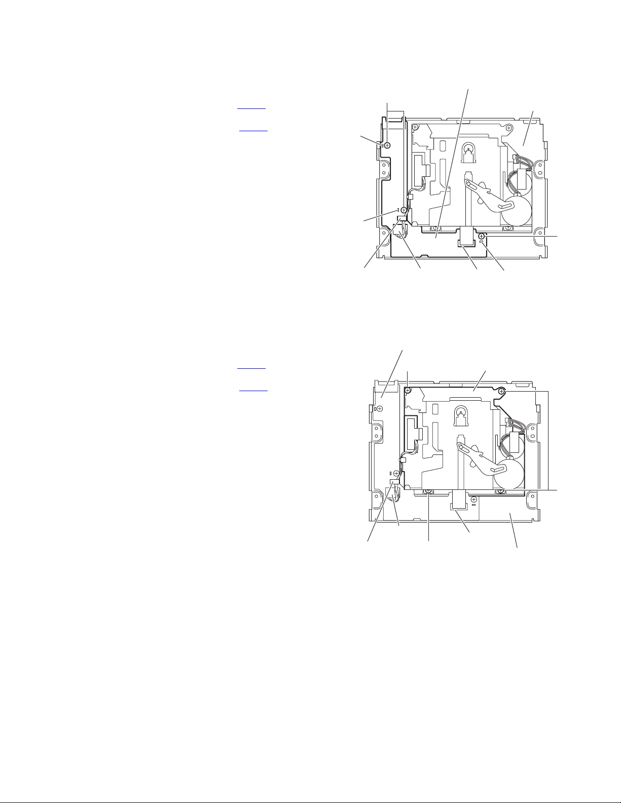
3.1.2 Removing the heat sink
(See Figs.3 and 4)
(1) From the back side of the main body, remove the six
screws B attaching the heat sink. (See Fig.3.)
(2) Remove the heat sink from the main body.
Note:
• Before attaching the heat sink, attach the cooling rubbers on
the power amplifier IC. (See Fig.4)
• When attaching the heat sink, set the projections b on the
rear bracket in the holes of the heat sink. (See Fig.3.)
3.1.3 Removing the rear bracket
(See Fig.4)
• Remove the heat sink.
(1) From the back side of the main body, remove the seven
screws C, two screws D and screw E attaching the rear
bracket.
(2) Remove the rear bracket from the main body.
Rear bracket
B
C
B
B
Fig.3
Cooling rubbers
Heat sink
bb
CD
3.1.4 Removing the bottom chassis assembly
(See Fig.5)
• Remove the front panel assembly, heat sink and rear bracket.
(1) From the bottom side of the main body, remove the four
screws F attaching the bottom chassis assembly.
(2) Take out the bottom chassis assembly from the main body.
Reference:
When attaching the bottom chassis assembly, set the projections c of the main body in the holes of the bottom chassis assembly.
C
Rear bracket
Bottom chassis assembly
Power amplifier IC
Fig.4
E
C
FF
1-8 (No.MA235)
c
Fig.5
Page 9
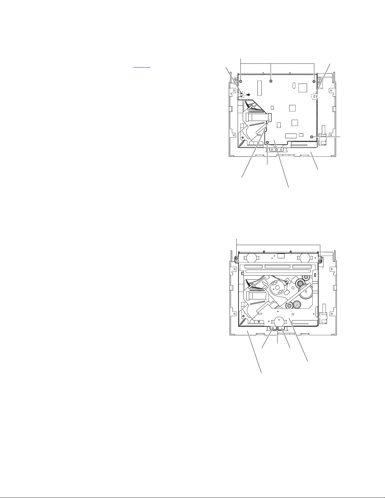
3.1.5 Removing the cassette mechanism control board
(See Fig.6)
• Remove the front panel assembly, heat sink, rear bracket and
bottom chassis assembly.
(1) From the inside of the bottom chassis assembly, discon-
nect the card wire from the connector CN403
sette mechanism control board.
(2) Disconnect the wire from the connector CN402
sette mechanism control board.
(3) Remove the three screws G attaching the cassette mech-
anism control board.
(4) Take out the cassette mechanism control board from the
bottom chassis assembly.
Reference:
• When attaching the cassette mechanism control board, set
the projections d of the bottom chassis assembly in the
holes of the cassette mechanism control board.
• After attaching the cassette mechanism control board, fix
the wire with the wire clamp as before.
on the cas-
on the cas-
Cassette mechanism control board
G
d
d
Bottom chassis assembly
G
3.1.6 Removing the cassette mechanism assembly
(See Fig.7)
• Remove the front panel assembly, heat sink, rear bracket and
bottom chassis assembly.
(1) From the inside of the bottom chassis assembly, discon-
nect the card wire from the connector CN403
sette mechanism control board.
(2) Disconnect the wire from the connector CN402 on the cas-
sette mechanism control board.
(3) Remove the four screws H attaching the cassette mecha-
nism assembly.
Reference:
After attaching the cassette mechanism control board, fix the
wire with the wire clamp as before.
on the cas-
Wire clamp
Cassette mechanism control board
H
CN402
Wire clamp
H
CN403CN402
Fig.6
Cassette mechanism assembly
CN403
Bottom chassis assembly
d
H
Fig.7
(No.MA235)1-9
Page 10

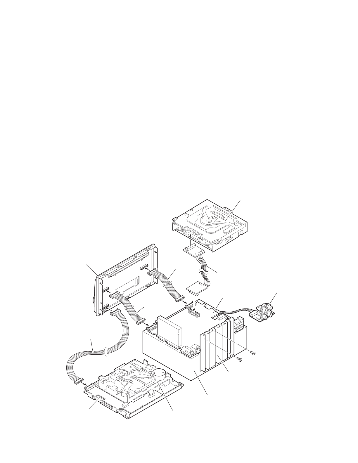
3.1.7 Removing the func board
(See Fig.8)
• Remove the front panel assembly, heat sink, rear bracket and
bottom chassis assembly.
(1) From the bottom side of the main body, disconnect the wire
from the connector CN321
(2) Remove the screw J and take out the func board from the
main body.
3.1.8 Removing the middle chassis assembly
(See Fig.8)
• Remove the front panel assembly, heat sink, rear bracket and
bottom chassis assembly.
(1) From the bottom side of the main body, remove the four
screws K attaching the middle chassis assembly.
(2) Disconnect the connector CN705
middle chassis assembly from the CD mechanism assembly in an upward direction.
on the func board.
of the main board on the
Middle chassis assembly
Main board
CN705
KK
3.1.9 Removing the main board
(See Fig.9)
• Remove the front panel assembly, heat sink, rear bracket, bot-
tom chassis assembly and middle chassis assembly.
(1) From the top side of the middle chassis assembly, discon-
nect the wire from the connector CN323
(2) Remove the four screws M attaching the main board on the
middle chassis.
(3) Remove the main board from the middle chassis.
Reference:
When attaching the main board, set the projections e of the
middle chassis in the holes of the main board.
on the main board.
M
CN321
J
e
Func board
Fig.8
Main board
CN323
e
M
1-10 (No.MA235)
M
Middle chassis
Fig.9
Page 11
3.1.10 Removing the CD mechanism control board
(See Fig.10)
• Remove the front panel assembly, heat sink, rear bracket, bot-
tom chassis assembly and middle chassis assembly.
(1) From the inside of the top chassis assembly, disconnect
the card wire from the connector CN601
anism control board.
(2) Remove the five screws N attaching the CD mechanism
control board.
(3) Lift the CD mechanism control board to remove the joint f
and remove the joint g in the direction of the arrow.
on the CD mech-
N
g
f
N
3.1.11 Removing the CD mechanism assembly
(See Fig.11)
• Remove the front panel assembly, heat sink, rear bracket, bot-
tom chassis assembly, middle chassis assembly and CD
mechanism control board.
(1) From the inside of the top chassis assembly, remove the
three screws P attaching the CD mechanism assembly.
(2) Take out the CD mechanism assembly from the top chas-
sis.
Reference:
When attaching the CD mechanism assembly, set the projections h of the top chassis assembly in the holes of the CD
mechanism assembly.
CN601
P
N
CD mechanism control board
h h
Top chassis assembly
Fig.10
P
CD mechanism assembly
Top chassis assembly
Fig.11
(No.MA235)1-11
Page 12

3.1.12 Removing the switch board
(See Fig.12)
• Remove the front panel assembly.
(1) From the inside of front panel assembly, remove the eight
screws Q attaching the switch board.
(2) Remove the volume knob from the front side of the front
panel assembly in the direction of the arrow while lifting the
switch board little by little.
(3) Release the sections j while extending the lower section of
the front panel assembly in the direction of the arrow and
take out the switch board.
Front panel assembly
Switch board
Q
QQ
Front panel assembly
Volume knob
j
Fig.12
1-12 (No.MA235)
Page 13

SECTION 4
ADJUSTMENT
4.1 Adjustment method
Test instruments required for adjustment
(1) Digital oscilloscope (100MHz)
(2) Frequency counter meter
(3) Electric voltmeter
(4) Wow & flutter meter
(5) Test tapes
• VT724...........................For DOLBY level measurement
• VT739..............For playback frequency measurement
• VT712....For wow flutter & tape speed measurement
• VT703........................For head azimuth measurement
(6) Torque gauge............................Cassette type for CTG-N
(Mechanism adjustment)
(7) Laser power meter(Reader:LP800102)
(8) Prove for MD (Reader:LP8010-02)
(9) Pre masterd disc (TGYS-1)
(10)Test disc (JVC:CTS1000)
Measuring conditions (Amplifier section)
• Power supply voltage.............. DC14.4V (11V to 16V allowance)
• Load impedance............ 4Ω (4Ω to 8Ω allowance)
• Line out level/Impedance..............1.0V/20k load (250 nWb/m)
Standard volume position
Balance and Bass, Treble volume, Fader : Center (Indication "0")
Loudness, Dolby NR, Sound, Cruise : Off
Volume position is about 2V at speaker output with following
conditions, Playback the test tape VT721.
AM mode 999kHz/62dB, INT/400Hz, 30%
modulation signal on receiving.
FM mono mode 97.9MHz/66dB, INT/400Hz, 22.5kHz
deviation pilot off mono
FM stereo mode 1kHz, 67.5kHz dev. pilot 7.5kHz dev.
Output level 0dB (1µV,50Ω/open terminal)
(No.MA235)1-13
Page 14
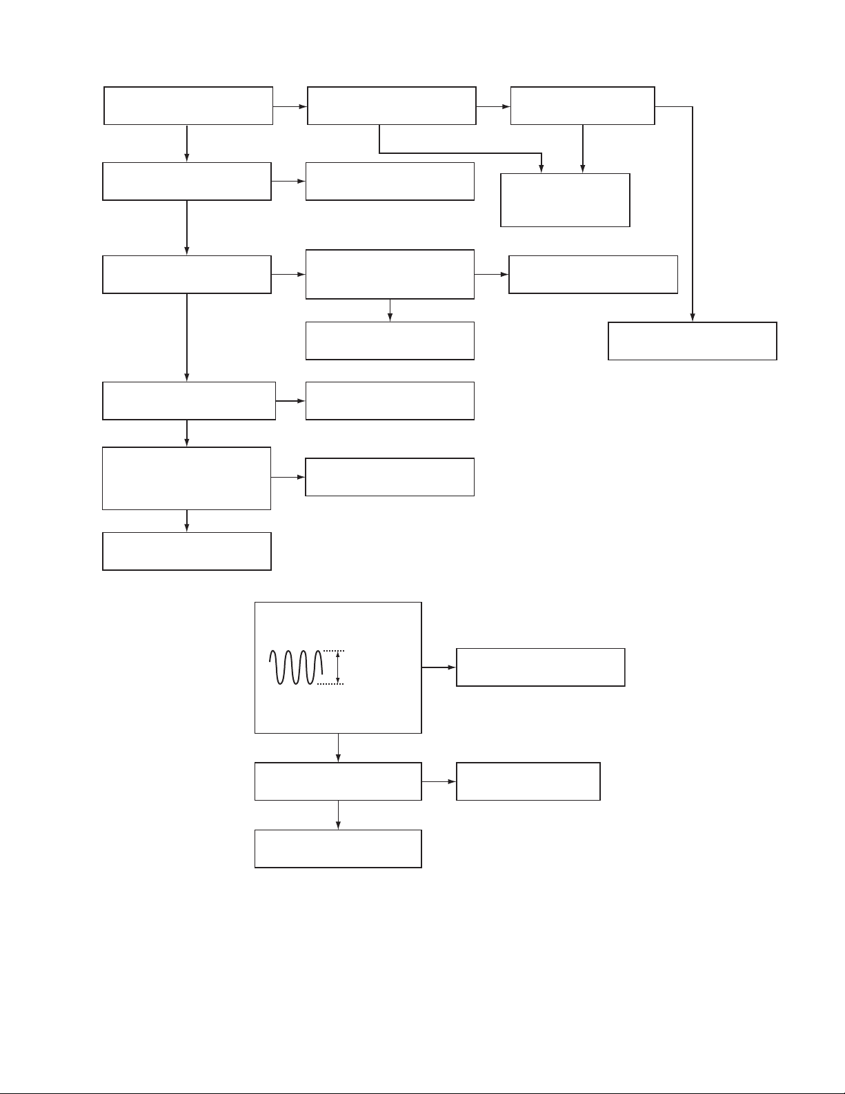
Information for using a car audio service jig
(1) We're advancing efforts to make our extension cords common for all car audio products.
Please use this type of extension cord as follows.
(2) As a U-shape type top cover is employed, this type of extension cord is needed to check operation of the mechanism assembly
after disassembly.
(3) Extension cord : EXTSH002-22P ( 22 pin extension cord ) For connection between the mechanism assembly and main board.
EXTXC004-20P ( 20 pin extension cord ) For connection between the front panel assembly and main board.
EXTXC004-16P ( 16 pin extension cord ) For connection between the front panel assembly and main board.
EXTXC004-16P ( 16 pin extension cord ) For connection between the front panel assembly and cassette mechanism assembly.
(4) Check for mechanism driving section such as motor ,etc.
Disassembly method
(1) Remove the front panel assembly.
(2) Remove the heat sink.
(3) Remove the rear bracket.
(4) Remove the bottom chassis assembly and middle chassis assembly.
(5) Remove the main board.
(6) Remove the CD mechanism assembly.
(7) Reattach the heat sink with two screws to the main board. (Refer to Disassembly method.)
(8) Connect the main board, front panel assembly, bottom chassis assembly and CD mechanism assembly with the extension
cords.
CAUTION :
Be sure to attach a heat sink on the power amplifier IC of a main board when supplying the power.
If voltage is applied without attaching the heat sink, the
power amplifier IC will be destroyed by heat.
CD mechanism assembly
Front panel assembly
EXTXC004-16P
Bottom chassis assembly
EXTXC004-20P
EXTXC004-16P
Cassette mechanism assembly
EXTSH002-22P
Main board
Heat sink
*The box etc. is used as a stand.
Func board
1-14 (No.MA235)
Page 15

4.2 Service mode
Set up
Press POWER ON [SEL] [POWER] [CD EJECT] together more than 2 sec.
UP,DW button to select
SEL button to determination
DEL EPROM EEPROM clear
CD ERROR CD error history call change by FF button E1 to TOTAL
DEL CD CD error history clear
MAIN TEMP Templature indication of main board
VERSION Micon version indication
For next operation, service mode is stop automaticaly.
1. No input signal (key operation) more than 5 sec.
2. press other key without SEL,UP,DOWN.
3. ACC to OFF.
(No.MA235)1-15
Page 16

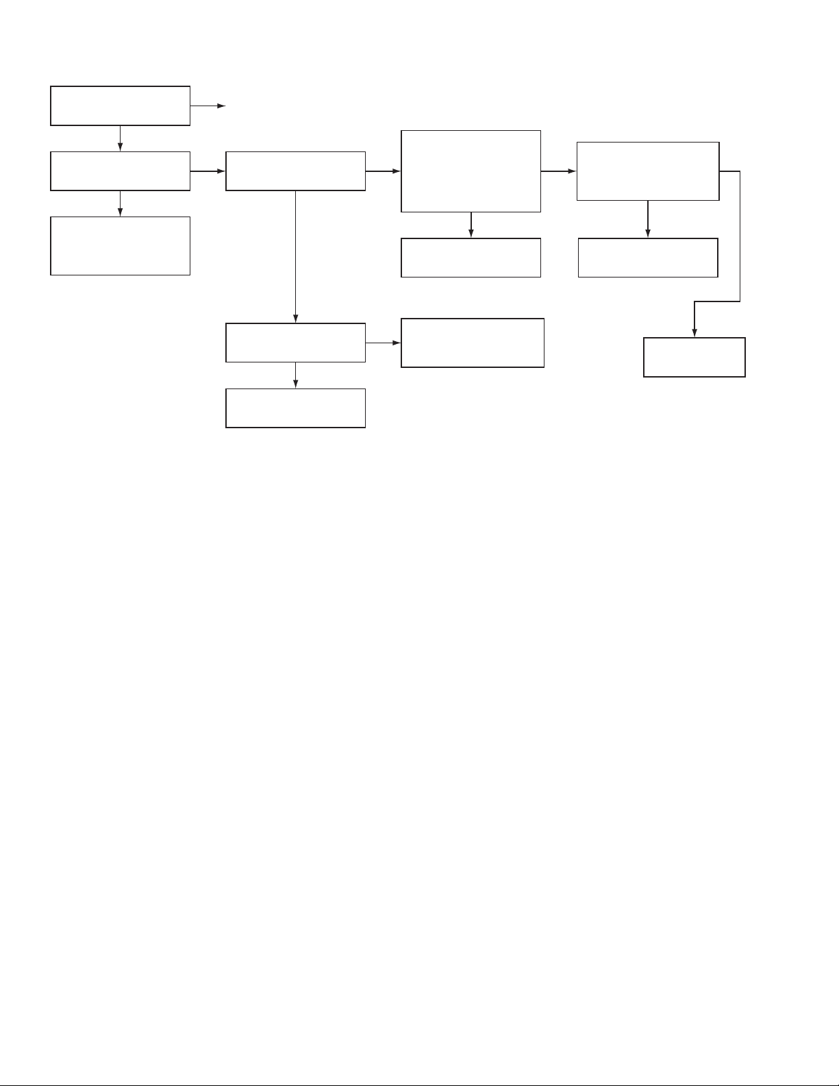
5.1 Feed section
SECTION 5
TROUBLESHOOTING
Is the voltage present at both
sides of the feed motor?
Is the voltage output at pin 17
and pin 18 of IC681?
Is the voltage input at pin 24
of IC681?
Is the voltage output at pin 40
of IC621?
Is the power supply present
at pin 6, pin 15, pin 25, pin 39,
pin 43, pin 48, pin 51 and pin
64 of IC621?
Check the connections of
CD8V power supply.
5.2 Focus section
NO
NO
NO
NO
NO
YES
YES
YES YES
YES
YES
Check the feed motor.
Check the connections
between the feed motor and
IC681.
Is the power supply present
at pin 10, pin 19 and pin 28
of IC681?
NO
Check the connections of
CD8V power supply.
Check the connections
between IC681 and IC621.
Check IC621.
Check IC681.
When the lens is moving:
4V
Does the S-search waveform
appear at IC681 pin 13 and
pin 14?
NO
Is the voltage input at pin 1
and pin 2 of IC681?
NO
Is the voltage output at pin 33
of IC621?
NO
Is the power supply present
at pin 6, pin 15, pin 25, pin 39,
pin 43, pin 48, pin 51 and pin
64 of IC621?
NO
YES
Check the pickup and
its connections.
Is the power supply present
YES YES
at pin 10, pin 19 and pin 28
of IC681?
NO
Check the connections of
CD8V power supply.
YES
Check the connections
between IC681 and IC621.
YES
Check IC621.
Check IC681.
Check the connections of
CD8V power supply.
1-16 (No.MA235)
Page 17
5.3 Spindle section
Is the disk rotated?
NO
Is the voltage output at pin 15
and pin 16 of IC681?
NO
Is the voltage input at pin 26
of IC681?
NO
Is the voltage output at pin 41
of IC621?
NO
Is the power supply present
at pin 6, pin 15, pin 25, pin 39,
pin 43, pin 48, pin 51 and pin
64 of IC621?
NO
YES
Does the RF signal appear at
YES
pin 19 of IC601?
YES
Check the spindle motor and
its wiring.
Is the power supply present
YES YES
at pin 10, pin 19 and pin 28
of IC681?
NO
Check the connections of
CD8V power supply.
YES
Check the connections
between IC681 and IC621.
YES
Check IC621.
Is the RF waveform at pin
19 of IC601 distorted?
NONO
Check the circuits in
the vicinity of IC601
or the pickup.
Check IC681.
YES
Proceed to the Tracking
section
Check the connections of
CD8V power supply.
5.4 Tracking section
When the disc is rotated
at first:
Approx. 1.2V
Is the tracking error signal
output at pin 11 of IC601?
NO
Check the circuits in IC601 or
the vicinity of IC601.
NO
Replace IC601 or repair the
malfunction connection point
YES
YES
Check the pickup and
its connections.
Check IC601.
(No.MA235)1-17
Page 18
5.5 Signal processing section
Is the sound output from
both channels (L, R)?
NO
No sound from either
channel.
NO
Compare the L-ch and
R-ch to locate the
defective point.
YES
Normal
YES
Is 9V present at pin 40
of IC151?
Is 9V present at pin 10
of IC901?
Check IC901 and its
peripheral circuits.
NO
NO
Is the audio signal
(including sampling
YES YES
output components)
output to pins 1 and 7 of
IC572 during playback?
NO
Check IC572 and its
peripheral circuits.
Check the connections
YES
between pin 40 of IC151
and pin 10 of IC901.
Is the audio signal output
at pin 36 and pin 37 of
IC151 during playback?
NO
Check IC151 and its
peripheral circuits.
YES
Check the power
amplifier IC181.
1-18 (No.MA235)
Page 19

5.6 Maintenance of laser pickup
(1) Cleaning the pick up lens
Before you replace the pick up, please try to clean the lens
with a alcohol soaked cotton swab.
(2) Life of the laser diode
When the life of the laser diode has expired, the following
symptoms will appear.
• The level of RF output (EFM output: amplitude of eye
pattern) will be low.
5.7 Replacement of laser pickup
Turn of the power switch and, disconnect the
power cord.
Replace the pickup with a normal one. (Refer
to "Removing the pickup unit" on the previous page.)
Is RF output
1.3 0.4Vp-p?
NO
Replace it.
YES
OK
(3) Semi-fixed resistor on the APC PC board
The semi-fixed resistor on the APC printed circuit board
which is attached to the pickup is used to adjust the laser
power.Since this adjustment should be performed to match
the characteristics of the whole optical block, do not touch
the semi-fixed resistor.
If the laser power is lower than the specified value, the laser diode is almost worn out, and the laser pickup should
be replaced. If the semi-fixed resistor is adjusted while the
pickup is functioning normally, the laser pickup may be
damaged due to excessive current.
Plug the power cord in, and turn the power on.
At this time, check that the laser emits for about
seconds and the objective lens moves up and down.
Note: Do not observe the laser beam directly.
Play a disc.
Check the eye-pattern at
pin 19 of IC601.
Finish.
(No.MA235)1-19
Page 20
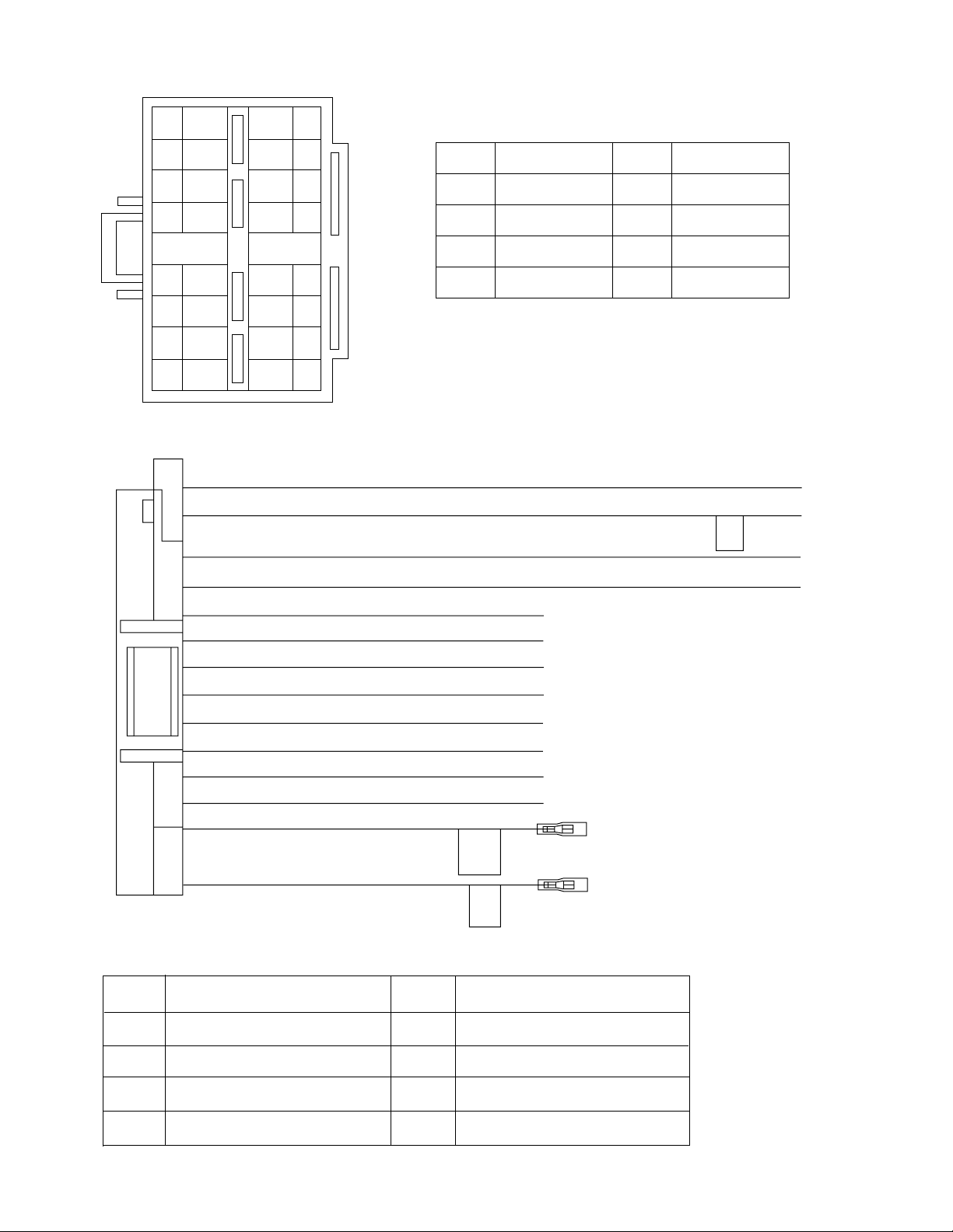
5.8 16 PIN CORD DIAGRAM
BK
8
RD
7
YL
16
15
OR/WH
BK
Black
GN
Green
6
5
4
3
2
1
BL/WH
BL
WH
GN
VI
GY
16 YL
8 BK
7 RD
15 OR/WH
3 GN
11 GN/BK
2 VI
14
NC
NC
13
WH/BK
12
GN/BK
11
10
VI/BK
GY/BK
9
MEMORY
GND
ACC
ILL
RL+
RL-
RR+
RD
BL
Red
Blue
WH White
VI Violet
GY
YL
Gray
Yellow
OR Orange
GND
RR
FR
FL
RL
REMOTE
10 VI/BK
4 WH
12 WH/BK
1 GY
9 GY/BK
5 BL/WH
6 BL
Rear Right
Front Right
Front Left
Rear Left
Remote out
RR-
FL+
FL-
FR+
FR-
REMOTE
ANT
ANT
ACC
ILL
GND
MEMORY
REMOTE
OUTPUT
ONLY
POWER
ANTENNA
Auto Antenna
ACC Line
Illuminations Control
Ground
Memory Backup Battery+
1-20 (No.MA235)
Page 21

(No.MA235)1-21
Page 22

Victor Company of Japan, Limited
Mobile Entertainment Business Group Mobile Entertainment Category 10-1,1chome,Ohwatari-machi,Maebashi-city,371-8543,Japan
(No.MA235)
Printed in Japan
VPT
Page 23
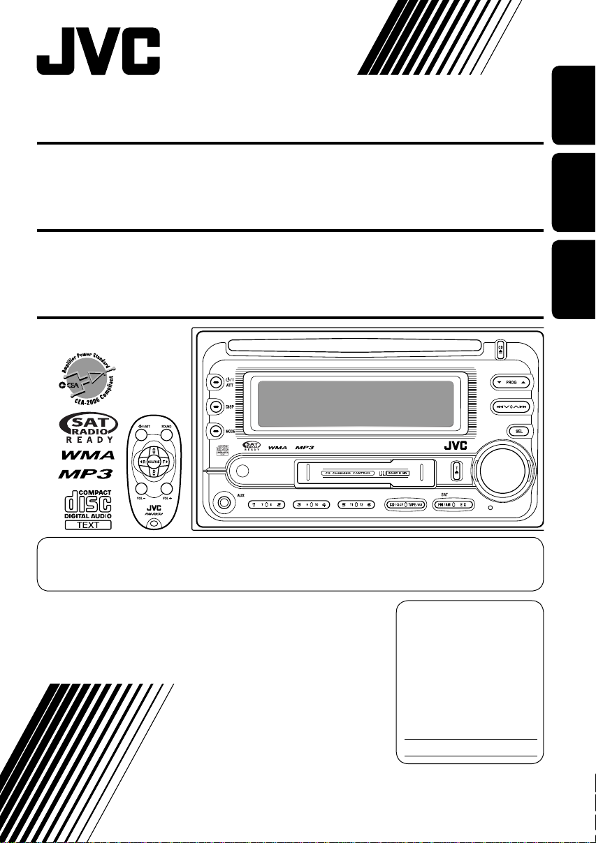
CD/CASSETTE RECEIVER KW-XC410/KW-XC400
ENGLISH
RECEPTOR CON CD/CASSETTE KW-XC410/KW-XC400
RECEPTEUR CD/CASSETTE KW-XC410/KW-XC400
For canceling the display demonstration, see page 8.
Para cancelar la demostración en pantalla, consulte la página 8.
Pour annuler la démonstration des affichages, référez-vous à la page 8.
For installation and connections, refer to the separate manual.
Para la instalación y las conexiones, refiérase al manual separado.
Pour l’installation et les raccordements, se référer au manuel séparé.
INSTRUCTIONS
MANUAL DE INSTRUCCIONES
MANUEL D’INSTRUCTIONS
For customer Use:
Enter below the Model
No. and Serial No. which
are located on the top or
bottom of the cabinet.
Retain this information
for future reference.
Model No.
Serial No.
ESPAÑOL
FRANÇAIS
GET0320-001B
[J]
Page 24

Thank you for purchasing a JVC product.
Please read all instructions carefully before operation, to ensure your complete understanding and to
obtain the best possible performance from the unit.
ENGLISH
INFORMATION (For U.S.A.)
This equipment has been tested and found to comply with the limits for a Class B digital device,
pursuant to Part 15 of the FCC Rules. These limits are designed to provide reasonable protection
against harmful interference in a residential installation. This equipment generates, uses, and can
radiate radio frequency energy and, if not installed and used in accordance with the instructions,
may cause harmful interference to radio communications. However, there is no guarantee that
interference will not occur in a particular installation. If this equipment does cause harmful
interference to radio or television reception, which can be determined by turning the equipment
off and on, the user is encouraged to try to correct the interference by one or more of the
following measures:
– Reorient or relocate the receiving antenna.
– Increase the separation between the equipment and receiver.
– Connect the equipment into an outlet on a circuit different from that to which the receiver is
connected.
– Consult the dealer or an experienced radio/TV technician for help.
IMPORTANT FOR LASER PRODUCTS
1. CLASS 1 LASER PRODUCT
2. CAUTION: Do not open the top cover. There are no user serviceable parts inside the unit; leave
all servicing to qualified service personnel.
3. CAUTION: Visible and invisible laser radiation when open and interlock failed or defeated.
Avoid direct exposure to beam.
Warning:
If you need to operate the unit while driving,
be sure to look ahead carefully or you may
be involved in a traffic accident.
How to reset your unit
This will reset the microcomputer. Your
preset adjustments will also be erased.
2
Caution on volume setting:
Discs produce very little noise compared
with other sources. Lower the volume
before playing a disc to avoid damaging
the speakers by the sudden increase of the
output level.
How to forcibly eject a disc
If a disc cannot be recognized or cannot be
ejected, eject the disc as follows.
• If this does not work, reset your unit.
• Be careful not to drop the disc when it
ejects.
Page 25

Contents
How to reset your unit ........................... 2
How to forcibly eject a disc ................... 2
How to read this manual ........................ 4
How to use the MODE button ............... 4
Control panel —
KW-XC410/KW-XC400 ............... 5
Parts identification ................................. 5
Remote controller — RM-RK50
Main elements and features ................... 6
... 6
Getting started ....................... 7
Basic operations .................................. 7
Canceling the display demonstrations ... 8
Setting the clock .................................... 8
Radio operations ................... 9
Listening to the radio ........................... 9
Storing stations in memory .................... 9
Listening to a preset station ................... 10
Scanning broadcast stations ................... 10
Assigning titles to the stations ............... 11
Disc operations ...................... 12
Playing a disc in the unit ..................... 12
Playing discs in the CD changer ........... 13
Other main functions ............................. 15
Changing the display information ......... 15
Selecting the playback modes ................ 16
Tape operations ..................... 17
Playing a tape ..................................... 17
Finding the beginning of a tune ............. 17
Other convenient tape functions ............ 17
Sound adjustments ................ 18
Selecting preset sound modes
(EQ: equalizer) ................................. 18
Adjusting the sound ............................... 18
Storing your own sound adjustments ..... 19
General settings — PSM ......... 20
Basic procedure ..................................... 20
External component operations
... 23
Playing an external component ............ 23
Satellite radio operations ....... 24
Listening to the SIRIUS Satellite radio... 25
Listening to the XM Satellite radio ....... 25
Storing channels in memory .................. 26
Listening to a preset channel ................. 26
Maintenance .......................... 27
Handling discs ....................................... 27
Handling cassettes ................................. 27
More about this unit ............... 28
Troubleshooting ..................... 31
ENGLISH
For safety....
• Do not raise the volume level too much, as
this will block outside sounds, making driving
dangerous.
• Stop the car before performing any
complicated operations.
Specifications ......................... 33
Temperature inside the car....
If you have parked the car for a long time in
hot or cold weather, wait until the temperature
in the car becomes normal before operating the
unit.
3
Page 26
How to read this manual
The following methods are used to make the
explanations simple and easy-to-understand:
• Some related tips and notes are explained in
ENGLISH
“More about this unit” (see pages 28 – 30).
• Button operations are mainly explained with
the illustrations as follows:
Press briefly.
How to use the MODE button
Press MODE repeatedly to select the different
functions available during play.
Time countdown indicator
Press repeatedly.
Press either one.
Press and hold until
your desired response
begins.
Press and hold both
buttons at the same
time.
The following marks are used to indicate...
: Built-in CD player operations.
: External CD changer operations.
This unit is equipped with the steering
wheel remote control function.
• See the Installation/Connection Manual
(separate volume) for connection.
Ex.: When “SSM” is selected
While listening to the radio:
• You cannot select “SSM” or “SCAN”
if you are listening to the station stored
in the EX (extra) button, see page 10 for
details.
SSM SCAN MONO
Canceled
(Station frequency)*
While listening to a disc:
–10 +10
(Track no. and
Elapsed playing time)*
While listening to a tape:
DOLBY B B.SKIP REPEAT
While adjusting the sound mode:
• Pressing MODE allows you to store the
adjusted sound mode into memory. (See
page 19 for details.)
REPEAT RANDOM
Canceled
Canceled
(Playback direction)*
INTRO
* Depending on the level meter setting. (See
page 20 for details.)
4
Page 27
Control panel — KW-XC410/KW-XC400
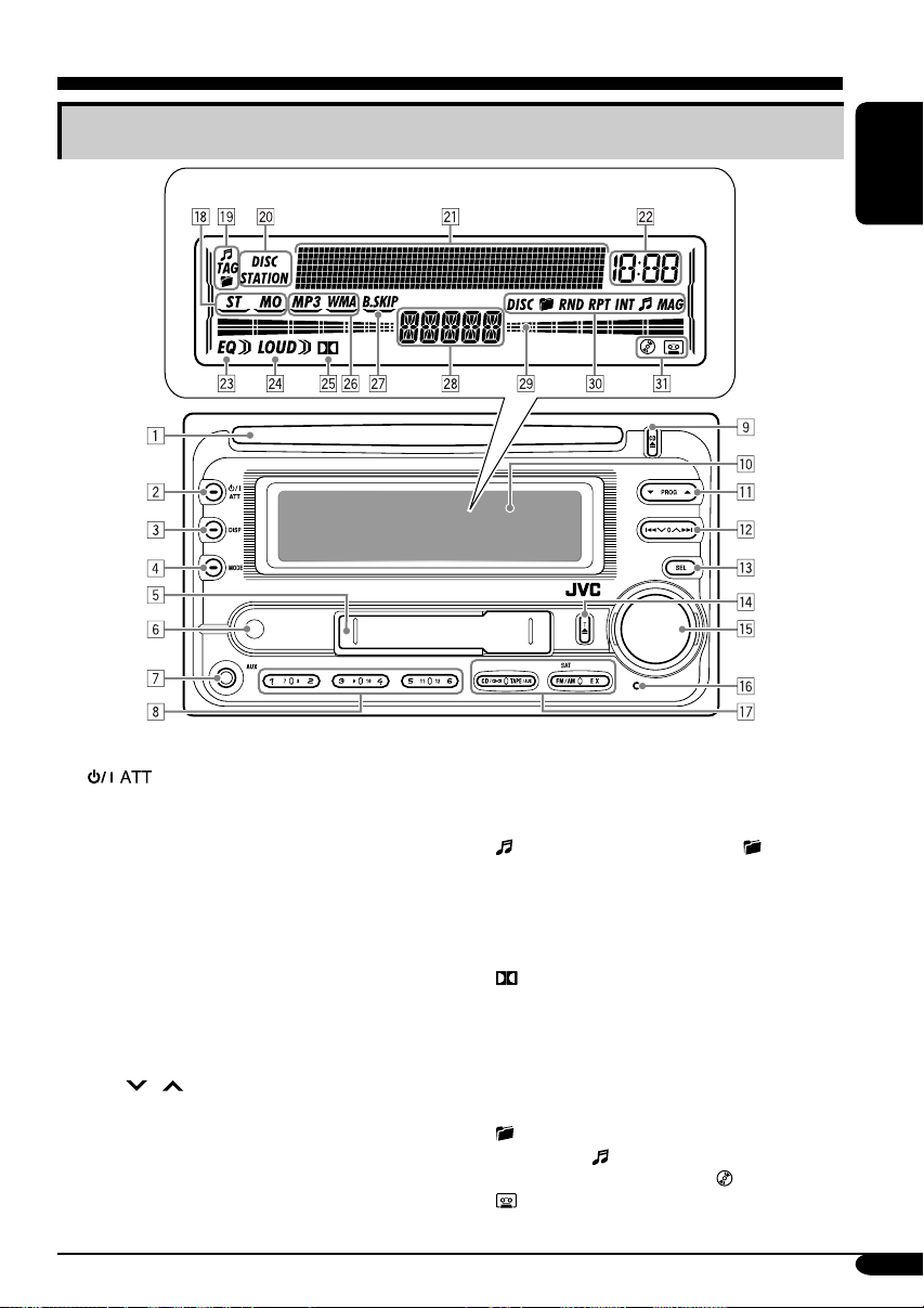
Parts identification
Display window
ENGLISH
1 Loading slot
2
3 DISP (display) button
4 MODE button
5 Cassette compartment
6 Remote sensor
• DO NOT expose the remote sensor to
7 AUX (auxiliary) input jack
8 Number buttons
9 CD 0 (CD eject) button
p Display window
q 5 (up) / ∞ (down) buttons
PROG (program) 5 / ∞ buttons
w 4
e SEL (select) button
r T 0 (tape eject) button
t Control dial
y Reset button
u Source buttons—CD/CD-CH, TAPE/AUX,
(standby/on attenuator) button
strong light (direct sunlight or artificial
lighting).
/ ¢ buttons
FM/AM SAT (satellite), EX (extra)
Display window
i Tuner reception indicators—ST (stereo),
MO (monaural)
o Disc information indicators—
(track/file), TAG (ID3 Tag), (folder)
; Text name indicators—DISC, STATION
a Main display, level meter
s Clock indicator
d EQ (equalizer) indicator
f LOUD (loudness) indicator
g
(Dolby B NR) indicator
h Playback disc indicators—MP3, WMA
j B.SKIP (blank skip) indicator
k Source display
l Level meter, volume meter, time countdown
indicator
/ Playback mode indicators—DISC,
(folder), RND (random), RPT (repeat),
INT (intro),
z Loaded source indicators—
(tape)
(track/file), MAG (magazine)
(disc),
5
Page 28
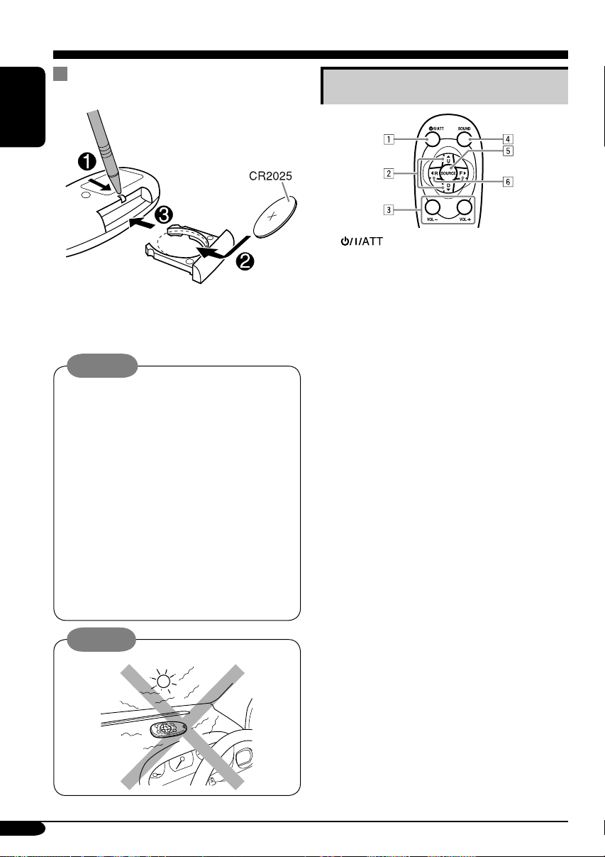
Remote controller — RM-RK50
Installing the lithium coin battery
(CR2025)
ENGLISH
• When operating, aim the remote controller
directly at the remote sensor on the unit.
Make sure there is no obstacle in between.
Warning:
• Do not install any battery other than
CR2025 or its equivalent; otherwise, it
may explode.
• Store the battery in a place where children
cannot reach to avoid risk of accident.
• To prevent the battery from over-heating,
cracking, or starting a fire:
– Do not recharge, short, disassemble,
heat the battery, or dispose of it in a fire.
– Do not leave the battery with other
metallic materials.
– Do not poke the battery with tweezers or
similar tools.
– Wrap the battery with tape and insulate
when throwing away or saving it.
Caution:
Main elements and features
1 (standby/on/attenuator) button
•
Turns the power on if pressed briefly or
attenuates the sound when the power is on.
• Turns the power off if pressed and held.
2 5 U (up) / D (down) ∞ buttons
•
Changes the FM/AM bands with 5 U only.
•
Changes the preset stations with D ∞ only.
• Changes the folder of the MP3/WMA
discs.
•
Changes the tape directions with 5 U only.
• While playing an MP3 disc on an
MP3-compatible CD changer:
– Changes the disc if pressed briefly.
– Changes the folder if pressed and held.
• While listening to the satellite
(SIRIUS or XM) radio:
– Changes the categories.
3 VOL – / VOL + buttons
• Adjusts the volume level.
4 SOUND button
• Selects the sound mode (EQ: equalizer).
5 SOURCE button
• Selects the source.
6 2 R (reverse) / F (forward) 3 buttons
• Searches for stations if pressed briefly.
• Fast-forwards or reverses the track if
pressed and held.
• Changes the tracks of the disc if pressed
briefly.
• Fast-forwards or reverses the tape if
pressed and held.*
• Finds the beginning of a tune (MMS)
while listening to a tape if pressed
briefly.*
• While listening to the satellite radio:
– Changes the channels if pressed briefly.
– Changes the channels rapidly if pressed
and held.
* To release these operations, press 5 U.
Playback resumes.
6
Page 29
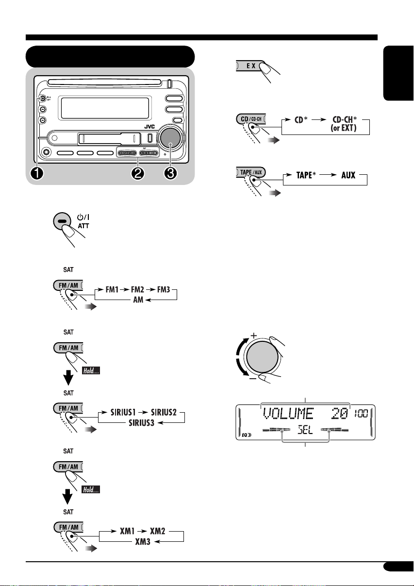
Getting started
Basic operations
~ Turn on the power.
Ÿ For FM/AM tuner
For SIRIUS Satellite radio*
For your favorite station
• Stored your favorite
station, see page 10
for details.
For CD/CD-CH
For TAPE/AUX
• Select “CD-CH” when using an Apple
iPod is a trademark of Apple
* You cannot select these sources if they
®
iPod
or a JVC D. player (see page 23).
Computer, Inc., registered in the U.S.
and other countries.
are not ready or not connected.
! Adjust the volume.
ENGLISH
For XM Satellite radio*
Volume level appears.
Volume level indicator
⁄ Adjust the sound as you want.
(See pages 18 and 19.)
7
Page 30
To drop the volume in a moment (ATT)
To restore the sound, press
it again.
ENGLISH
4 Finish the procedure.
To turn off the power
Canceling the display
demonstrations
If no operations are done for about 20 seconds,
display demonstration starts.
[Initial: DEMO ON] —see page 20.
1
2
To activate the display demonstration
In step 3 above...
Setting the clock
1
Set the hour and minute.
2
1 Select “CLOCK HOUR,” then
adjust the hour.
2 Select “CLOCK MIN,” (minute)
then adjust the minute.
3
3 Finish the procedure.
8
Page 31

Radio operations
Listening to the radio
~
Lights up when receiving an FM stereo
broadcast with sufficient signal strength.
Selected band appears.
2 Select the desired station frequencies.
ENGLISH
When an FM stereo broadcast is hard to
receive
1
2
Lights up when monaural mode is activated.
Reception improves, but stereo effect will
be lost.
To restore the stereo effect, repeat the same
procedure. Then, in step 2, select “MONO
OFF.”
Ÿ Start searching for a station.
When a station is received, searching
stops.
To stop searching, press the same
button again.
To tune in to a station manually
In step Ÿ above...
1
Storing stations in memory
You can preset six stations for each band.
FM station automatic presetting —
SSM (Strong-station Sequential
Memory)
1
Select the FM band (FM1 – FM3)
you want to store into.
To be continued....
9
Page 32

2
ENGLISH
3
“SSM” flashes, then disappears when
automatic presetting is over.
Local FM stations with the strongest signals are
searched and stored automatically in the FM
band.
Manual presetting
Ex.: Storing FM station of 92.5 MHz into the
preset number 4 of the FM1 band.
1
Listening to a preset station
1
2 Select the preset station (1 – 6) you
want.
or
To tune in to your favorite station (EX)
If you press the button
again, the previous source
will be played back again.
2
3
Preset number flashes for a while.
Storing your favorite station into the
EX (extra) button
Ex.: Storing your favorite FM station of
92.5 MHz into the EX button
While listening to an FM station, tune in
to your favorite station, then....
10
Scanning broadcast stations
1
2 Start scanning.
Each time a broadcast is tuned in, scanning
stops for about 5 seconds (tuned frequency
appears on the display), and you can check
what program is now being broadcast.
3 Start listening to the program.
Page 33

Assigning titles to the stations
You can assign titles to 30 station frequencies
(including both FM and AM). Each station
name can be assigned up to 10 characters.
However, you cannot assign title to the station
frequency stored in the EX button.
1 Tune in to the station you would like
to assign a title to.
2 Enter the assigning mode.
4 Finish the procedure.
ENGLISH
To erase the entire title
In step 3 on the left...
To change the information shown on the
display
3 Assign a title.
1 Select a character set.
2 Select a character.
3 Move to the next (or previous)
character position.
Station frequency
(and Preset no.)
* If no title is assigned, “NO NAME” appears
for a while.
Assigned title*
Available characters
Upper case
Lower case
Numbers and symbols
4 Repeat steps 1 to 3 until you
finish entering the title.
11
Page 34

Disc operations
Playing a disc in the unit
ENGLISH
All tracks will be played repeatedly until
you change the source or eject the disc.
• When inserting an MP3 or a WMA disc:
Total folder
number
Total file
number
• When inserting an audio CD or a CD Text
disc:
Total track number
of the inserted disc
Total playing time
of the inserted disc
CD Text: Disc title/performer =
Track title appears automatically
(see page 15).
Current track
number*
Elapsed playing
2
time
2
*
To stop play and eject the disc
The source changes to the last
selected source.
12
Disc information appears
automatically (see page 15).
Current track
number*
Elapsed playing
2
time
2
*
1
Either the MP3 or WMA indicator lights up
*
depending on the detected file.
2
*
Depending on the level meter setting. (See
page 20 for details.)
Page 35

Playing discs in the CD changer
All disc in the magazine will be played
repeatedly until you change the source.
• Ejecting the magazine will also stop playing.
About the CD changer
It is recommended to use a JVC MP3compatible CD changer with your unit.
• You can also connect other CH-X series
CD changers (except CH-X99 and
CH-X100). However, they are not
compatible with MP3 discs, so you cannot
play back MP3 discs.
• You cannot play any WMA disc in the CD
changer.
• You cannot use the KD-MK series CD
changers with this unit.
• Disc text information recorded in the CD
Text can be displayed when a JVC CD
Text compatible CD changer is connected.
~
If you have changed “EXT INPUT”
*
setting to “EXT INPUT”(see page
22), you cannot select the CD
changer.
Ÿ Select a disc.
For disc number from 01 – 06:
For disc number from 07 – 12:
Selected disc number
Track number
ENGLISH
For connection, see Installation/Connection
Manual (separate volume).
13
Page 36

• When the current disc is an MP3 disc:
ENGLISH
To fast-forward or reverse the track
Folder name*
1
Disc information appears
automatically (see page 15).
Current track
number*
Elapsed playing
2
time*
2
• When the current disc is an audio CD or a
CD Text disc:
CD Text: Disc title/performer =
Track title appears automatically
(see page 15).
Current track
number
2
*
Elapsed playing
2
time
*
To go to the next or previous tracks
To go to the next or previous folders for
MP3 and WMA discs
(For MP3/WMA
discs)
(For MP3 discs)
To locate a particular track (for CD) or
folder (for MP3 or WMA discs) directly
To select a number from 01 – 06:
To select a number from 07 – 12:
1
*
“ROOT” appears if no folder is included in
the disc.
2
*
Depending on the level meter setting. (See
page 20 for details.)
14
• To use folder search on MP3/WMA discs, it
is required that folders are assigned with
2-digit numbers at the beginning of their
folder names—01, 02, 03, and so on.
To select a particular track in a folder (for
MP3 or WMA disc):
Page 37

Other main functions
Skipping a track quickly during play
Changing the display information
ENGLISH
Only possible on JVC
MP3-compatible CD changer
• For MP3 or WMA disc, you can skip a track
within the same folder.
Ex.: To select track 32 while playing track 6
1
2
First time you press 5 / ∞ button, the track
skips to the nearest higher or lower track
with a track number of multiple ten (ex.
10th, 20th, 30th).
Then each time you press the button, you
can skip 10 tracks.
• After the last track, the first track will be
selected and vice versa.
–10 +10
3
While playing an audio CD or a CD
Text
While playing an MP3 or a WMA disc
• When “TAG DISP” is set to
“TAG ON” (see page 22)
• When “TAG DISP” is set to
“TAG OFF”
Prohibiting disc ejection
You can lock a disc in the loading slot.
To cancel the prohibition, repeat the same
procedure.
: Current track/file number and
Elapsed playing time
3
*
If the current disc is an audio CD,
“NO NAME” appears.
4
*
If an MP3/WMA file does not have ID3 tags,
folder name and file name appear. In this
case, the TAG indicator will not light up.
15
Page 38

Selecting the playback modes
You can use only one of the following playback modes at a time.
ENGLISH
Select your desired playback mode.
1 2
Repeat play
Ex.: When “TRACK RPT” is selected
Random play
Ex.: When “DISC RND” is selected
Intro scan
Ex.: When “TRACK INT” is selected
Mode Plays repeatedly
TRACK RPT : The current track.
• RPT and
FOLDER RPT*
•
DISC RPT*
1
: All tracks of the current folder.
and RPT light up.
2
: All tracks of the current disc.
light up.
• DISC and RPT light up.
REPEAT OFF : Cancels.
Mode Plays at random
FOLDER RND*1: All tracks of the current folder,
then tracks of the next folder and so
on.
•
DISC RND : All tracks of the current disc.
• DISC and RND light up.
MAG RND*
2
• RND and MAG light up.
RANDOM OFF : Cancels.
Mode
TRACK INT : All tracks of the current disc.
• INT and
FOLDER INT*
•
DISC INT*
• DISC and INT light up.
INTRO OFF : Cancels.
2
and RND light up.
: All tracks of the inserted discs.
Plays the beginning 15 seconds of...
1
: The first track of every folder of
the current disc.
and INT light up.
: The first tracks of the inserted
discs.
light up.
1
*
Only while playing an MP3 disc or a WMA disc.
2
*
Only while playing discs in the CD changer.
16
Page 39

Tape operations
Playing a tape
Playback starts automatically. When one
side of the tape reaches its end during play,
the other side of the tape automatically
starts playing. (Auto Reverse)
To change the playback direction
FWD PLAY
(Forward play)
To stop play and eject the cassette
The source changes to the last
selected source.
REV PLAY
(Reverse play)
Finding the beginning of a tune
Multi Music Scan (MMS) allows you to
automatically start playback from the beginning
of a specified tune.
Specify the tune you want to locate
(how many tunes ahead of or before the
current tune)
When the beginning
of the specified tune is
located, playback starts
automatically.
3
*
Goes back to the beginning of the current
tune.
Other convenient tape functions
1
ENGLISH
To fast-forward or rewind a tape
When the tape reaches its
end while fast-forwarding,
the tape direction will change
automatically.
To stop fast-forwarding or rewinding, press
the PROG button.
Prohibiting tape ejection
You can lock a tape in the loading slot.
To cancel the prohibition, repeat the same
procedure.
2
• To turn on or off Dolby B NR*
( lights up on the display)
• To skip blank portions on the tape
( lights up on the display)
• To play the current tune repeatedly
( lights up on the display)
*4 Manufactured under license from Dolby
Laboratories. “Dolby” and the doubleD symbol are trademarks of Dolby
Laboratories.
4
17
Page 40

Sound adjustments
Selecting preset sound modes
(EQ: equalizer)
ENGLISH
You can select a preset sound mode suitable to
the music genre.
~
Ÿ
FLAT O Hard Rock O R & B O
POP O JAZZ O DanceMusic O
Country O Reggae O Classic O
USER 1 O USER 2 O USER 3 O
(back to the beginning)
To select the sound mode directly
You can select the sound mode directly using
the remote controller.
Adjusting the sound
You can adjust the sound characteristics to your
preference.
1
2
Indication Range
1
FADER*
Adjust the front and rear
speaker balance.
BAL (balance)
Adjust the left and right
speaker balance.
LOUD
(loudness)
Boost low and high
frequencies to produce a
well-balanced sound at low
volume level.
VOLUME*
Adjust the volume.
*1 If you are using a two-speaker system, set
*
*
2
the fader level to “00.”
2
Normally the control dial works as the
volume control. So you do not have to select
“VOLUME” to adjust the volume level.
3
Depending on the amplifier gain control
setting. (See page 22 for details.)
R06 (Rear only)
to
F06 (Front only)
L06 (Left only)
to
R06 (Right only)
LOUD ON
LOUD OFF
00 (min.) to
30 or 50 (max.)*
3
18
Page 41

Storing your own sound
adjustments
4 Adjust the selected sound elements
while the indication on step 3 is
shown.
You can adjust the sound modes and store your
own adjustments in memory.
1
2 Select one of the sound mode to
adjust.
Ex.: When “JAZZ” is selected
3 Select the sound elements to adjust
while the selected sound mode is
shown.
Indication
LEVEL –06
(min.) to
+06
(max.)
FREQ 60Hz
80Hz
100Hz
120Hz
WIDTH 1 (min.)
to
4 (max.)
Preset values
LOW MID HIGH
–06
(min.) to
+06
(max.)
1 (min.)
to
2 (max.)
–06
(min.) to
+06
(max.)
8kHz
10kHz
12kHz
15kHz
5 Repeat steps 3 and 4 to set (or
adjust) the other sound elements.
6 Select one of the user sound modes
(USER 1, USER 2, USER 3).
ENGLISH
LOW LEVEL O LOW FREQ. O
LOW WIDTH O MID LEVEL O
MID WIDTH O HIGH LEVEL O
HIGH FREQ. O (back to the
beginning)
• (LOW, MID, HIGH) LEVEL:
Adjust the enhancement level.
• (LOW, HIGH) FREQ:
Select the center frequency to adjust.
• (LOW, MID) WIDTH :
Select the band width level.
7 Store the adjustments.
“MEMORY” appears for a
while.
19
Page 42

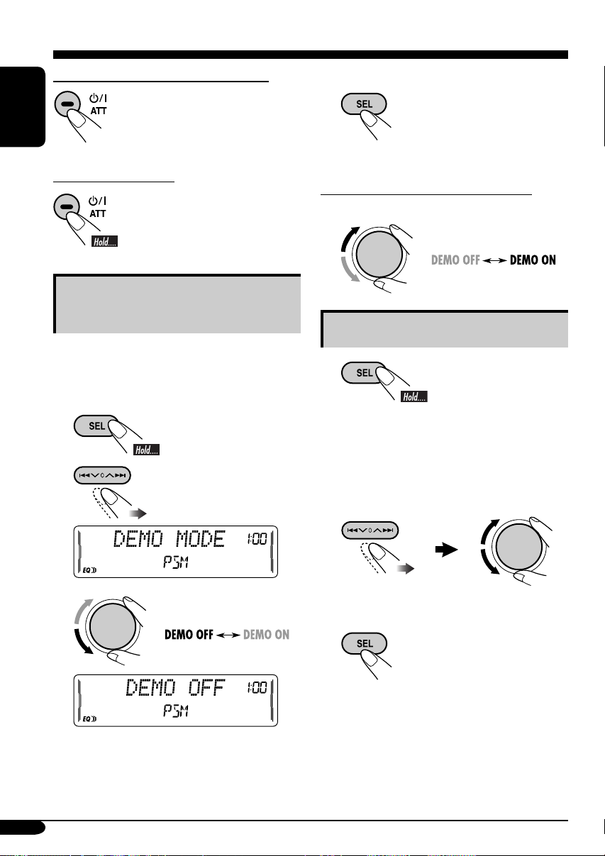
General settings — PSM
Basic procedure
3 Adjust the PSM item selected.
You can change PSM (Preferred Setting Mode)
items (except “SID”) listed in the table that
ENGLISH
follows.
1
2 Select a PSM item.
Indications Selectable settings, [reference page]
DEMO MODE
Display
demonstration
CLOCK HOUR
Hour adjustment
CLOCK MIN
Minute adjustment
CLOCK DISP
Clock display
LEVELMETER
Audio level meter
DEMO ON : [Initial]; Display demonstration will be activated
DEMO OFF : Cancels.
1 – 12, [8]
[Initial: 1 (1:00)]
00 – 59, [8]
[Initial: 00 (1:00)]
CLOCK ON : Clock time is shown on the display at all times even
CLOCK OFF : [Initial];
You can select one of the four different level meter patterns or a
demonstration of all the patterns.
LEVEL ALL [Initial] O LEVEL 1 O LEVEL 2 O LEVEL 3 O
LEVEL 4 O LEVEL OFF (canceled) O (back to the beginning)
LEVEL ALL : Demonstrates all the level meter patterns, each for
4 Repeat steps 2 and 3 to adjust the
5 Finish the procedure.
automatically if no operation is done for about
20 seconds, [8].
when the unit is turned off.
on
. If the unit is turned off,
the clock time for about 5 seconds.
about 20 seconds.
other PSM items if necessary.
Clock time is shown
when the unit is turned
pressing DISP will show
20
Page 43

Indications Selectable settings, [reference page]
3
1, *2
1, *2
4
*
1
AUTO : [Initial]; The built-in clock is automatically adjusted using
the clock data provided via the satellite radio channel.
OFF : Cancels.
Select your residential area from one of the following time zones for clock
adjustment.
EASTERN [Initial] “ ATLAN TIC “ NEWFOUND (Newfoundland)
“ ALASKA “ PACIFIC “ MOUNTAIN “ CENTRAL “ (back to
the beginning).
Activate this if your residential area is subject to DST.
ON : [Initial]; Activates daylight savings time.
OFF : Cancels.
The 12-digit SIRIUS identification number scrolls on the display
5 seconds after “SID” is selected, [24].
AUTO : [Initial]; Dims the display when you turn on the headlights.
ON : Activates dimmer.
OFF : Cancels
1 – 10 : Adjust the display contrast to make the display indications
clear and legible.
[Initial: 5]
ONCE : [Initial]; Scrolls the disc information once.
AUTO : Repeats scrolling (5-second intervals in between).
OFF : Cancels.
• Pressing DISP for more than one second can scroll the display regardless
of the setting.
CLK ADJ*
Clock
adjustment
T-ZO NE*
Time zone
DST*
Daylight saving
time
SID*
SIRIUS® ID
DIMMER
Dimmer
CONTRAST
Display contrast
SCROLL
Scroll
ENGLISH
1
*
Displayed only when SIRIUS Satellite radio or XM Satellite radio is connected.
2
*
Displayed only when “CLK ADJ” is set to “AUTO.”
3
*
Displayed only when SIRIUS Satellite radio is connected.
4
*
Some characters or symbols will not be shown correctly (and will be blanked) or substituted on
the display.
21
Page 44

Indications Selectable settings, [reference page]
EXT INPUT*
External input
ENGLISH
AUX ADJUST
Auxiliary input
level adjustment
TAG DISP
Tag display
AMP GAIN
Amplifier gain
control
IF FILTER
IF filter
AREA
Tuner channel
interval
1
*
Cannot be selected if the source is “CD-CH” or “EXT.”
1
CHANGER : [Initial]; To use a JVC CD changer, [13], an Apple iPod
or a JVC D. player, [23], a JVC compatible satellite
(SIRIUS/XM) tuner, [24].
EXT INPUT : To use another external component, [23].
AUX ADJ 00 – AUX ADJ 05: Adjust the auxiliary input level
accordingly, to avoid the sudden increase of the output
level when changing the source from external component
connected to the AUX input jack on the control panel.
[Initial: AUX ADJ 00]
TAG ON : [Initial]; Shows the ID3 tag while playing MP3/WMA
tracks, [15].
TAG OFF : Cancels.
You can change the maximum volume level of this unit.
LOW PWR : VOLUME 00 – VOLUME 30 (Select this if the
maximum power of the speaker is less than 50 W to avoid
damaging the speaker.)
HIGH PWR : [Initial]; VOLUME 00 – VOLUME 50
AUTO : [Initial]; Increases the tuner selectivity to reduce
interference noises between close stations. (Stereo effect
may be lost.)
WIDE : Subject to the interference noises from adjacent stations,
but sound quality will not be degraded and maintains the
stereo effect.
AREA US : [Initial]; Select this when using the unit in North or
South America except for Middle South America.
(FM: 200 kHz; AM: 10 kHz)
AREA EU : Select this when using the unit in any other area than
North, Middle South, and South America. (FM: 50 kHz—
manual tuning, 100 kHz—auto search; AM: 9 kHz)
AREA SA : Select this when using the unit in Middle South America.
(FM: 100 kHz; AM: 10 kHz)
22
Page 45

External component operations
This unit is ready for operating an Apple
®
iPod
or a JVC D. player from the control
panel.
• For details, refer also to the manual
supplied with the interface adapter
®
for iPod
KS-PD500.
—KS-PD100 or D. player—
Playing an external component
You can connect an external component to....
• CD changer jack on the rear using:
– Line Input Adapter—KS-U57 (not
supplied) or AUX Input Adapter—
KS-U58 (not supplied) for any other
components (except iPod or D. player).
– Interface adapter for iPod
(not supplied) for controlling iPod.
– D. player interface adapter—KS-PD500
(not supplied) for controlling D. player.
• AUX (auxiliary) input jack on the control
panel.
For connection, see Installation/Connection
Manual (separate volume).
®
—KS-PD100
~ For selecting the external
component connected to....
• AUX input jack
ENGLISH
• CD changer jack on the rear
using KS-U57 or KS-U58
If “EXT” does not appear, see page
22 and select the external input
(EXT INPUT).
• CD changer jack on the rear
using interface adapter for iPod
—KS-PD100 or for D. player—
KS-PD500
Ÿ Turn on the connected component
and start playing the source.
! Adjust the volume.
⁄ Adjust the sound as you want.
(See pages 18 and 19.)
23
Page 46

Satellite radio operations
This unit is Satellite (SAT) Radio Ready–
compatible with both SIRIUS Satellite radio
and XM Satellite radio.
ENGLISH
Before operating your satellite radio:
• For connection, see Installation/
Connection Manual (separate volume).
• Refer also to the Instructions supplied
with your SIRIUS Satellite radio or XM
Satellite radio.
• “SIRIUS” and the SIRIUS dog logo are
registered trademarks of SIRIUS Satellite
Radio Inc.
• XM and its corresponding logos are
registered trademarks of XM Satellite
Radio Inc.
• “SAT Radio,” the SAT Radio logo and all
related marks are trademarks of SIRIUS
Satellite Radio Inc., and XM Satellite
Radio, Inc.
Listening to the satellite radio
Connect either one of the following (separately
purchased) to the CD changer jack on the rear
of this unit.
• JVC SIRIUS radio DLP—Down Link
Processor, for listening to the SIRIUS
Satellite radio.
• XMDirect™ Universal Tuner Box
using a JVC Smart Digital Adapter—
XMDJVC100 (not supplied), for listening to
the XM Satellite radio.
Activate your SIRIUS subscription after
connection:
1
2
JVC DLP starts updating all the SIRIUS
channels.
Once completed, JVC DLP tunes in to the
preset channel, CH184.
3
Check your SIRIUS ID, see page 21.
4 Contact SIRIUS on the internet at
<http://activate.siriusradio.com/> to
activate your subscription, or you
can call SIRIUS toll-free at
1-888-539-SIRIUS (7474).
“SUB UPDT PRESS ANY KEY” scrolls
on the display once subscription has been
completed.
GCI (Global Control Information) update:
• If channels are updated after subscription,
updating starts automatically.
“UPDATING” flashes and no sound can be
heard.
• Update takes a few minutes to complete.
• During update, you cannot operate your
satellite radio.
24
Activate your XM subscription after
connection:
• Only Channel 0, 1, and 247 are available
before activation.
1
Page 47
2
Selecting a particular category (SPORTS,
ENTERTAINMENT, etc.) allows you to
enjoy only the channels from the selected
category.
ENGLISH
3 Select a channel for listening.
XMDirect™ Universal Tuner Box starts
updating all the XM channels. “Channel 1”
is tuned in automatically.
3
Check your XM Satellite radio ID
labelled on the casing of the
XMDirect™ Universal Tuner Box, or
tune in to “Channel 0” (see page 26).
4 Contact XM Satellite radio on
the internet at <http://xmradio.
com/activation/> to activate your
subscription, or you can call
1-800-XM-RADIO (1-800-967-2346).
Once completed, the unit tunes in to one
of the available channels (Channel 4 or
higher).
Listening to the
SIRIUS Satellite radio
1
2 Select a category.
You can tune in to all the channels of every
category by selecting “ALL.”
Holding the button changes the channels
rapidly.
• When changing the category or channel,
invalid and unsubscribed channels are
skipped.
Listening to the
XM Satellite radio
1
2 Select a channel for listening.
Holding the button changes the channels
rapidly.
Category/channel search
You can search for programs by category
(Category Search) or channel number (Channel
Search).
• In Category Search, you can tune in to the
channels of the selected category. Category
Search begins from the currently selected
channel. The selected channel number flashes
on the display.
• In Channel Search, you can tune in to all
the channels (including non-categorised
channels).
To be continued...
25
Page 48

1 Select a category (Category Search).
ENGLISH
2 Select a channel for listening.
Current channel number
Ex.: When you select ”COUNTRY”
for Category Search
If no operation is done for about
7 seconds, Category Search is canceled.
In Channel Search, channel name and
channel number appear on the display
during search.
• While searching, invalid and unsubscribed
channels are skipped.
Storing channels in memory
You can preset six channels for each band.
Ex.: Storing a channel into preset number 4.
1 Tune in to a channel you want.
2
Preset number flashes for
a while.
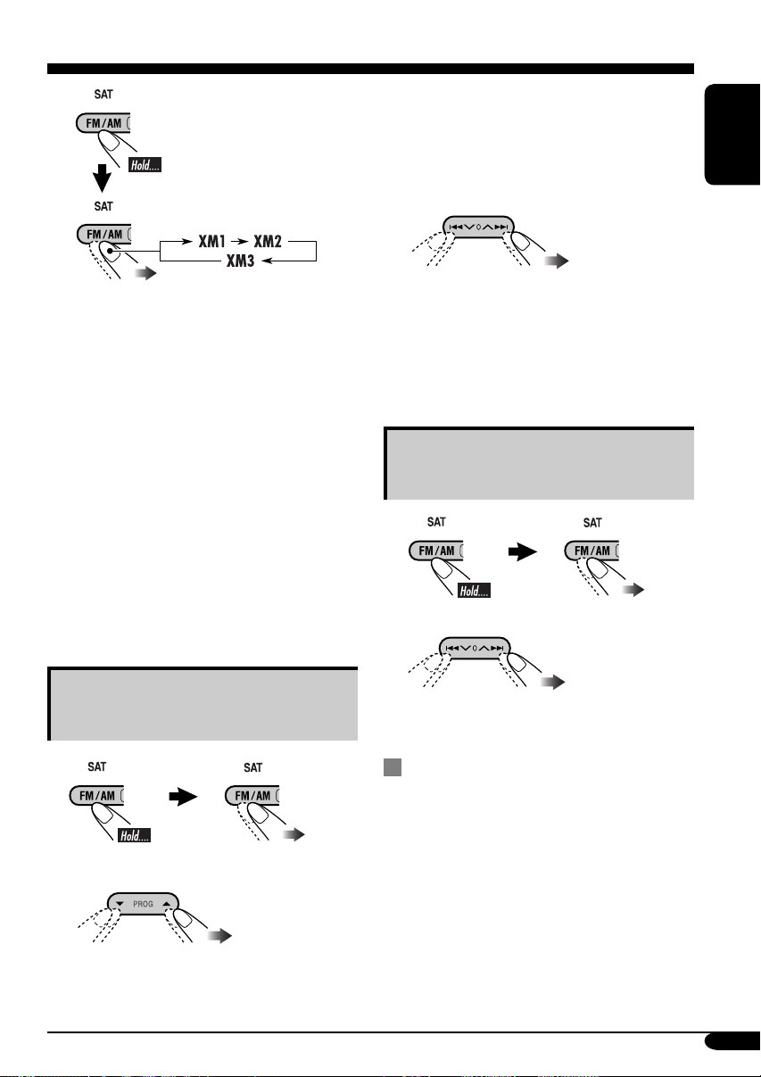
Listening to a preset channel
1 Select either SIRIUS Satellite radio
or XM Satellite radio.
2 Select the preset channel (1 – 6) you
want.
Checking the XM Satellite radio ID
While selecting “XM1,” “XM2,” or
“XM3,” select “Channel 0.”
The display alternately shows “RADIO ID” and
the 8-digit (alphanumeric) ID number.
To cancel the ID number display, select any
channel other than “Channel 0.”
26
To change the display information while
listening to a channel
Category name = Channel name = Artist name
= Composer name* = Song/program name/title
=
(back to the beginning)
* Only for SIRIUS Satellite radio.
Page 49

Maintenance
Handling discs
Moisture condensation
Moisture may condense on the lens inside the
CD player in the following cases:
• After starting the heater in the car.
• If it becomes very humid inside the car.
Should this occur, the CD player may
malfunction. In this case, eject the disc and
leave the unit turned on for a few hours until the
moisture evaporates.
How to handle discs
When removing a disc from
its case, press down the center
holder of the case and lift the
disc out, holding it by the edges.
• Always hold the disc by the
edges. Do not touch its recording surface.
When storing a disc into its case, gently insert
the disc around the center holder (with the
printed surface facing up).
• Make sure to store discs into the cases after
use.
Center holder
Do not use the following discs:
Warped
disc
Sticker
Disc
Handling cassettes
To clean the head
ENGLISH
Sticker
residue
Stick-on
label
To keep discs clean
A dirty disc may not play correctly.
If a disc does become dirty, wipe
it with a soft cloth in a straight line
from center to edge.
• Do not use any solvent (for example,
conventional record cleaner, spray, thinner,
benzine, etc.) to clean discs.
To play new discs
New discs may have some rough
spots around the inner and outer
edges. If such a disc is used, this
unit may reject the disc.
To remove these rough spots, rub the edges
with a pencil or ball-point pen, etc.
• Clean the heads after every 10 hours of use
using a wet-type head cleaning tape (available
at an audio store).
When the head becomes dirty, you may
realize the following symptoms:
– Sound quality is reduced.
– Sound level decreases.
– Sound drops out.
• Do not touch the highly-polished head with
any metallic or magnetic tools.
To keep the tape clean
• Always store the cassettes in their storage
cases after use.
• Do not store cassettes in the following places:
– Subject to direct sunlight
– With high humidity
– At extremely hot temperatures
27
Page 50

More about this unit
Basic operations
Turning on the power
• By pressing the source buttons on the unit,
you can also turn on the power. If the source
ENGLISH
is ready, playback also starts.
Turning off the power
• If you turn off the ignition key without
turning off this unit, the unit will
automatically turn on when you turn on the
ignition key next time. If the last selected
source is ready for playback (ex. a disc
or a tape is in the unit), playback starts
automatically.
• If you turn off the power while listening to a
disc, disc play will start from where playback
has been stopped previously, next time you
turn on the power.
Selecting the sources
• When no disc or cassette is loaded in the unit,
“CD” or “TAPE” cannot be selected.
• “SIRIUS,” “XM,” or “CD-CH” cannot be
selected when the target component is not
connected.
Tuner operations
Storing stations in memory
• During SSM search...
– All previously stored stations are erased and
stations are stored newly.
– Received stations are preset in No. 1 (lowest
frequency) to No. 6 (highest frequency).
– When SSM is over, the station stored in
No. 1 will be automatically tuned in.
• When storing a station manually, the
previously preset station is erased when
a new station is stored in the same preset
number.
Disc operations
Caution for DualDisc playback
• The Non-DVD side of a “DualDisc” does
not comply with the “Compact Disc Digital
Audio” standard. Therefore, the use of NonDVD side of a DualDisc on this product may
not be recommended.
General
• MP3 and WMA (Windows Media® Audio)
“tracks” (words “file” and “track” are used
interchangeably) are recorded in “folders.”
• This unit has been designed to reproduce
CDs/CD Texts, and CD-Rs (Recordable)/
CD-RWs (Rewritable) in audio CD (CD-DA),
MP3 and WMA format.
• When a disc has been loaded, selecting “CD”
for the playback source starts disc play.
Inserting a disc
• When a disc is inserted upside down, the disc
automatically ejects and the unit starts playing
the last selected source.
• Do not insert 8 cm (3-3/16”) discs (single
CD) and unusual shape discs (heart, flower,
etc.) into the loading slot.
Playing a disc
• While fast-forwarding or reversing on an MP3
or WMA disc, you can only hear intermittent
sounds.
28
Page 51

Playing a CD-R or CD-RW
• Use only “finalized” CD-Rs or CD-RWs.
• This unit can play back only files of the same
type which are first detected if a disc includes
both audio CD (CD-DA) files and
MP3/WMA files.
• This unit can play back multi-session discs;
however, unclosed sessions will be skipped
while playing.
• Some CD-Rs or CD-RWs may not play
back on this unit because of their disc
characteristics, or for the following reasons:
– Discs are dirty or scratched.
– Moisture condensation occurs on the lens
inside the unit.
– The pickup lens inside the unit is dirty.
– CD-R/CD-RW on which the files are
written with “Packet Write” method.
– There are improper recording conditions
(missing data, etc.) or media conditions
(stained, scratched, warped, etc.).
• CD-RWs may require a longer readout time
since the reflectance of CD-RWs is lower
than that of regular CDs.
• Do not use the following CD-Rs or CD-RWs:
– Discs with stickers, labels, or protective seal
stuck to the surface.
– Discs on which labels can be directly
printed by an ink jet printer.
Using these discs under high temperatures
or high humidity may cause malfunctions or
damage to the unit.
Playing an MP3/WMA disc
• This unit can play back MP3/WMA files
with the extension code <.mp3> or <.wma>
(regardless of the letter case—upper/lower).
• This unit can show the names of albums,
artists (performer), and ID3 Tag (Version 1.0,
1.1, 2.2, 2.3, or 2.4) for MP3 files and for
WMA files.
• This unit can display only one-byte
characters. No other characters can be
correctly displayed (see page 11).
• This unit can play back MP3/WMA files
meeting the conditions below:
– Bit rate: 8 kbps — 320 kbps
– Sampling frequency:
48 kHz, 44.1 kHz, 32 kHz (for MPEG-1)
24 kHz, 22.05 kHz, 16 kHz (for MPEG-2)
48 kHz, 44.1 kHz, 32 kHz (for WMA)
– Disc format: ISO 9660 Level 1/ Level 2,
Romeo, Joliet, Windows long file name
• The maximum number of characters for file/
folder names vary among the disc format used
(includes 4 extension characters—<.mp3> or
<.wma>).
– ISO 9660 Level 1: up to 12 characters
– ISO 9660 Level 2: up to 31 characters
– Romeo*: up to 128 (72) characters
– Joliet*: up to 64 (36) characters
– Windows long file name*: up to 128 (72)
characters
* The parenthetic figure is the maximum
number of characters for file/folder names
in case the total number of files and folders
is 313 or more.
• This unit can recognize a total of 512 files, of
200 folders, and of 8 hierarchies.
• This unit can play back files recorded in VBR
(variable bit rate).
Files recorded in VBR have a discrepancy
in elapsed time display, and do not show the
actual elapsed time. This difference becomes
noticeable especially after performing the
search function.
• This unit cannot play back the following files:
– MP3 files encoded with MP3i and
MP3 PRO format.
– MP3 files encoded in an unappropriated
format.
– MP3 files encoded with Layer 1/2.
– WMA files encoded with lossless,
professional, and voice format.
– WMA files which are not based upon
Windows Media
– WMA files copy-protected with DRM.
– Files which have the data such as WAVE,
ATRAC3, etc.
• The search function works but search speed is
not constant.
®
Audio.
To be continued....
ENGLISH
29
Page 52

Changing the source
• If you change the source, playback also stops
(without ejecting the disc).
Next time you select “CD” or “CD-CH” for
ENGLISH
the playback source, disc play starts from
where it has been stopped previously.
Ejecting a disc
• If the ejected disc is not removed within
15 seconds, the disc is automatically inserted
again into the loading slot to protect it from
dust. (Disc will not play this time.)
Tape operations
Playing a tape
• While locating a specified tune:
– If the tape is rewound to its beginning,
playback starts from the beginning of that
side.
– If the tape is fast-forwarded to the end, it is
reversed and played from the beginning of
the other side.
• In the following cases, Multi Music Scan
(MMS), Blank Skip, and Repeat Play may not
operate correctly:
– Tapes with tunes having long pianissimo
passages (very quiet parts) or non-recorded
portions.
– Tapes with short non-recorded sections.
– Tapes with high level noise or humming
between tunes.
– The Dolby NR setting does not match. For
example, if the tape is recorded with the
Dolby C NR.
• Do not use the following tape:
– Dirty or dusty tapes.
– Cassette with peeling labels.
– Loose tape which may become entangled
with the mechanism.
Changing the source
• If you change the source, playback also stops
(without ejecting the cassette).
Ignition key-off release
• When you turn off the ignition key with
a cassette in the compartment, the unit
automatically releases the tape from its head.
General settings—PSM
• If you change the “TAG DISP” setting from
“TAG OFF” to “TAG ON” while playing
MP3/WMA file, the tag display will be
activated when the next file starts playing.
• If you change the “AMP GAIN” setting
from “HIGH PWR” to “LOW PWR”
while the volume level is set higher than
“VOLUME 30,” the unit automatically
changes the volume level to “VOLUME 30.”
Other main functions
• If you try to assign a title to the 31st station
frequency, “NAME FULL” flashes. Delete
unwanted titles before assignment.
Satellite radio operations
• You can also connect the JVC SIRIUS radio
PnP (Plug and Play), using the JVC SIRIUS
radio adapter, KS-U100K (not supplied) to the
CD changer jack on the rear.
By turning on the power of the unit, you
can turn on/off the JVC PnP. However, you
cannot control it from this unit.
• To know more about SIRIUS Satellite radio
or to sign up, visit «http://www.sirius.com».
• For the latest channel listings and
programming information, or to sign up
for XM Satellite radio, visit «http://www.
xmradio.com».
• Microsoft and Windows Media are either registered trademarks or trademarks of Microsoft
Corporation in the United States and/or other countries.
30
Page 53

Troubleshooting
What appears to be trouble is not always serious. Check the following points before calling a service
center.
Symptoms Remedies/Causes
• Sound cannot be heard from the
speakers.
General
• The unit does not work at all. Reset the unit (see page 2).
• SSM automatic presetting does not
work.
FM/AM
• Static noise while listening to the radio. Connect the antenna firmly.
• Disc cannot be played back. Insert the disc correctly.
• CD-R/CD-RW cannot be played back.
• Tracks on the CD-R/CD-RW cannot be
skipped.
• Disc can be neither played back nor
ejected.
• Disc sound is sometimes interrupted. • Stop playback while driving on rough roads.
Disc playback
• “NO DISC” appears on the display. Insert a correct disc into the loading slot.
• Disc cannot be played back. • Use a disc with MP3/WMA tracks recorded in
• Noise is generated. Skip to another track or change the disc. (Do not
• A longer readout time is required
(“CHECK” keeps flashing on the
display).
MP3/WMA playback
• Tracks do not play back in the order
you have intended them to play.
• Elapsed playing time is not correct. This sometimes occurs during play. This is caused
• “NO FILES” appears on the display. Insert a disc that contains MP3/WMA tracks.
• A cassette cannot be inserted. Insert the cassette with the exposed tape facing
• Cassette can be neither played back nor
ejected.
• “NO TAPE” appears on the display. Insert a cassette correctly.
• Cassette tapes become hot. This is not a malfunction.
Tape playback
• Tape sound is at very low level and
sound quality is degraded.
• Adjust the volume to the optimum level.
• Check the cords and connections.
Store stations manually.
• Insert a finalized CD-R/CD-RW.
•
Finalize the CD-R/CD-RW with the component
which you used for recording.
• Unlock the disc (see page 15).
• Eject the disc forcibly (see page 2).
• Use an unscratched disc.
• Check the cords and connections.
the format compliant with ISO 9660 Level 1,
Level 2, Romeo, or Joliet.
• Add the extension code <.mp3> or <.wma> to
the file names.
add the extension code <.mp3> or <.wma> to
non-MP3 or WMA tracks.)
Do not use too many hierarchies and folders.
Playback order is determined when the files are
recorded.
by how the tracks are recorded on the disc.
right.
Unlock the cassette (see page 17).
Clean the tape head using a head cleaning tape.
ENGLISH
To be continued....
31
Page 54

Symptoms
Remedies/Causes
• “NO DISC” appears on the display.
ENGLISH
• “NO MAG” appears on the display. Insert the magazine.
• “RESET 8” appears on the display. Connect this unit and the CD changer correctly
CD changer
• “RESET 1” – “RESET 7” appears on
• The CD changer does not work at all. Reset the unit (see page 2).
• “CALL 1-888-539-SIRIUS TO
• No sound can be heard.
“UPDATING” appears on the
• Either “NO SIGNAL” scrolls or
• Either “NO ANTENNA” scrolls or
• “NO CH” appears on the display for
• “NO (information)*” scrolls on the
Satellite radio
• “---” appears on the display while
• “---” appears on the display for
• “OFF AIR” appears on the display
• “LOADING” appears on the display
• “RESET 8” appears on the display.
• Satellite radio does not work at all.
the display.
SUBSCRIBE” scrolls on the display
while listening to the SIRIUS
Satellite radio.
display.
“NO SIGNL” appears on the display.
“ANTENNA” appears on the display.
about 5 seconds, then returns to the
previous display while listening to
the SIRIUS Satellite radio.
display while listening to the SIRIUS
Satellite radio.
listening to the XM Satellite radio.
about 2 seconds, then returns to the
previous channel while listening to
the XM Satellite radio.
while listening to the XM Satellite
radio.
while listening to the XM Satellite
radio.
Insert a disc into the magazine.
and press the reset button of the CD changer.
Press the reset button of the CD changer.
Starts subscribing SIRIUS Satellite radio
(see page 24).
The unit is updating the channel information and
it takes a few minutes to complete.
Move to an area where signals are stronger.
Connect the antenna firmly.
No broadcast on the selected channel.
Select another channel or continue listening to the
previous channel.
No text information for the selected channel.
Selected channel is no longer available or is
unauthorized.
Select another channel or continue listening to the
previous channel.
Selected channel is not broadcasting at this time.
Select another channel or continue listening to the
previous channel.
The unit is loading the channel information
and audio. Text information are temporarily
unavailable.
Reconnect this unit and the satellite radio
correctly and press the reset button of this unit.
* NO CATEGORY, NO ARTIST, NO COMPOSER, and NO SONG/PROGRAM
32
Page 55

Specifications
AUDIO AMPLIFIER SECTION
Power Output:
18 W RMS × 4 Channels at 4 Ω
and ≤ 1% THD+N
Signal to Noise Ratio:
80 dBA (reference: 1 W into 4 Ω)
Load Impedance: 4 Ω (4 Ω to 8 Ω allowance)
Equalizer Control Range:
Low: ±12 dB (60 Hz, 80 Hz, 100 Hz, 120 Hz)
Mid: ±12 dB
High: ±12 dB (8 kHz, 10 kHz, 12 kHz, 15 kHz)
Frequency Response: 40 Hz to 20 000 Hz
Line-Out Level/Impedance:
2.0 V/20 kΩ load (full scale)
Output Impedance: 1 kΩ
Other Terminals: CD changer, AUX
(auxiliary) input jack,
Steering wheel remote input
TUNER SECTION
Frequency Range:
FM: 87.5 MHz to 107.9 MHz
(with channel interval set to 100 kHz
or 200 kHz)
87.5 MHz to 108.0 MHz
(with channel interval set to 50 kHz)
AM: 530 kHz to 1 710 kHz
(with channel interval set to 10 kHz)
531 kHz to 1 602 kHz
(with channel interval set to 9 kHz)
[FM Tuner]
Usable Sensitivity: 11.3 dBf (1.0 µV/75 Ω)
50 dB Quieting Sensitivity:
16.3 dBf (1.8 µV/75 Ω)
Alternate Channel Selectivity (400 kHz): 65 dB
Frequency Response: 40 Hz to 15 000 Hz
Stereo Separation: 35 dB
Capture Ratio: 1.5 dB
[AM Tuner]
Sensitivity: 20 µV
Selectivity: 35 dB
CD PLAYER SECTION
Type: Compact disc player
Signal Detection System: Non-contact optical
pickup (semiconductor laser)
Number of Channels: 2 channels (stereo)
Frequency Response: 5 Hz to 20 000 Hz
Dynamic Range: 96 dB
Signal-to-Noise Ratio: 98 dB
Wow and Flutter: Less than measurable limit
MP3 Decoding Format:
MPEG1/2 Audio Layer 3
Max. Bit Rate: 320 kbps
WMA (Windows Media
Format:
Max. Bit Rate: 192 kbps
®
Audio) Decoding
CASSETTE DECK SECTION
Wow and Flutter: 0.1 % (WRMS)
Fast-Wind Time: 100 sec. (C-60)
Frequency Response: 30 Hz to 16 000 Hz
(Normal tape)
Signal-to-Noise Ratio: (Normal tape)
Dolby B NR ON: 65 dB
Dolby B NR OFF: 56 dB
Stereo Separation: 40 dB
GENERAL
Power Requirement:
Operating Voltage:
DC 14.4 V (11 V to 16 V allowance)
Grounding System: Negative ground
Allowable Operating Temperature:
0°C to +40°C (32°F to 104°F)
Dimensions (W × H × D):
Installation Size (approx.):
178 mm × 100 mm × 158 mm
(7-1/16" × 3-15/16" × 6-1/4")
Set Size (approx.):
178 mm × 100 mm × 175 mm
(7-1/16" × 3-15/16" × 6-15/16")
Mass (approx.):
2.3 kg (5.1 lbs) (excluding accessories)
Design and specifications are subject to change
without notice.
If a kit is necessary for your car, consult
your telephone directory for the nearest car
audio speciality shop.
ENGLISH
33
Page 56

Having TROUBLE with operation?
Please reset your unit
Refer to page of How to reset your unit
Still having trouble??
USA ONLY
Call 1-800-252-5722
http://www.jvc.com
We can help you!
EN, SP, FR
© 2005 Victor Company of Japan, Limited
1105DTSMDTJEIN
Page 57

GET0320-002B
[J]
KW-XC410/KW-XC400
Installation/Connection Manual
Manual de instalación/conexión
Manuel d’installation/raccordement
1105DTSMDTJEIN
EN, SP, FR
© 2005 Victor Company of Japan, Limited
ENGLISH
This unit is designed to operate on 12 V DC, NEGATIVE ground
electrical systems. If your vehicle does not have this system, a
voltage inverter is required, which can be purchased at JVC car audio
dealers.
Parts list for installation and connection
The following parts are provided for this unit. After checking them,
please set them correctly.
Flat countersunk screws—M5 × 8 mm (M5 × 3/8")
Tornillos de cabeza avellanada plana—M5 × 8 mm (M5 × 3/8 pulgada)
Vis plat à tête fraisée—M5 × 8 mm (M5 × 3/8 pouces)
Binding screws—M5 × 8 mm (M5 × 3/8")
Tornillos de fijación—M5 × 8 mm (M5 × 3/8 pulgada)
Vis de serrage—M5 × 8 mm (M5 × 3/8 pouces)
ESPAÑOL
Esta unidad está diseñada para funcionar con 12 V de CC, con
sistemas eléctricos de masa NEGATIVA. Si su vehículo no posee
este sistema, será necesario un inversor de tensión, que puede ser
adquirido en los concesionarios de JVC de equipos de audio para
automóviles.
Lista de piezas para instalación y conexión
Con esta unidad se suministran las siguientes piezas. Después de
inspeccionarlas, colóquelas correctamente.
Power cord
Cordón de alimentación
Cordon d’alimentation
Battery
Pila
Pile
FRANÇAIS
Cet appareil est conçu pour fonctionner sur des sources de courant
continu de 12 V à masse NEGATIVE. Si votre véhicule n’offre pas ce
type d’alimentation, il vous faut un convertisseur de tension, que vous
pouvez acheter chez un revendeur d’autoradios JVC.
Liste des pièces pour l’installation et raccordement
Les pièces suivantes sont fournies avec cet appareil. Après vérification,
veuillez les placer correctement.
Remote controller
Control remoto
Télécommade
Plate for use with a Nissan car
Placa para usar con un automóvil Nissan
Plaque à utiliser avec une voiture Nissan
When installating the unit in a Nissan car
Cuando instale la unidad en un automóvil Nissan
Lors de l’installation de l’appareil dans une
voiture Nissan
Fix the supplied plate as illustrated.
Fije la placa suministrada de la manera indicada en la ilustración.
Fixez la plaque fournie comme montré sur l’illustration.
PRECAUTIONS on power supply and speaker
connections:
• DO NOT connect the speaker leads of the power cord to the
car battery; otherwise, the unit will be seriously damaged.
• BEFORE connecting the speaker leads of the power cord to the
speakers, check the speaker wiring in your car.
PRECAUCIONES sobre las conexiones de la fuente
de alimentación y de los altavoces:
• NO conecte los conductores de altavoz del cable de
alimentación a la batería de automóvil, pues podrían
producirse graves daños en la unidad.
• ANTES de conectar a los altavoces los conductores de altavoz del
cable de alimentación, verifique el conexionado de altavoz de su
automóvil.
Plate for use with a Nissan car
Placa para usar con un automóvil Nissan
Plaque à utiliser avec une voiture Nissan
PRECAUTIONS sur l’alimentation et la connexion
des enceintes:
• NE CONNECTEZ PAS les fils d’enceintes du cordon
d’alimentation à la batterie; sinon, l’appareil serait
sérieusement endommagé.
• AVANT de connecter les fils d’enceintes du cordon d’alimentation
aux enceintes, vérifiez le câblage des enceintes de votre voiture.
TROUBLESHOOTING
• The fuse blows.
* Are the red and black leads connected correctly?
• Power cannot be turned on.
* Is the yellow lead connected?
• No sound from the speakers.
* Is the speaker output lead short-circuited?
• Sound is distorted.
* Is the speaker output lead grounded?
* Are the “–” terminals of L and R speakers grounded in common?
• Noise interfere with sounds.
* Is the rear ground terminal connected to the car’s chassis using
shorter and thicker cords?
• This unit becomes hot.
* Is the speaker output lead grounded?
* Are the “–” terminals of L and R speakers grounded in common?
• This unit does not work at all.
* Have you reset your unit?
LOCALIZACION DE AVERIAS
• El fusible se quema.
* ¿Están los conductores rojo y negro correctamente conectados?
• No es posible conectar la alimentación.
* ¿Está el cable amarillo conectado?
• No sale sonido de los altavoces.
*
¿Está el cable de salida del altavoz cortocircuitado?
• El sonido presenta distorsión.
* ¿Está el cable de salida del altavoz conectado a masa?
* ¿Están los terminales “–” de los altavoces L y R conectados a una
masa común?
• Perturbación de ruido.
* ¿El terminal de tierra trasero está conectado al chasis del automóvil
utilizando los cordones más corto y más grueso?
• La unidad se calienta.
* ¿Está el cable de salida del altavoz conectado a masa?
* ¿Están los terminales “–” de los altavoces L y R conectados a una
masa común?
• Este receptor no funciona en absoluto.
* ¿Reinicializó el receptor?
1
EN CAS DE DIFFICULTES
• Le fusible saute.
* Les fils rouge et noir sont-ils racordés correctement?
• L’appareil ne peut pas être mise sous tension.
* Le fil jaune est-elle raccordée?
• Pas de son des enceintes.
* Le fil de sortie d’enceinte est-il court-circuité?
• Le son est déformé.
* Le fil de sortie d’enceinte est-il à la masse?
* Les bornes “–” des enceintes gauche et droit sont-elles mises ensemble
à la masse?
• Interférence avec les sons.
* La prise arrière de mise à la terre est-elle connectée au châssis de la
voiture avec un cordon court et épais?
• L’appareil devient chaud.
* Le fil de sortie d’enceinte est-il à la masse?
* Les bornes “–” des enceintes gauche et droit sont-elles mises ensemble
à la masse?
• Cet appareil ne fonctionne pas du tout.
* Avez-vous réinitialisé votre appareil?
Page 58

INSTALLATION
INSTALACION (MONTAJE EN EL
INSTALLATION (MONTAGE
(IN-DASH MOUNTING)
The following illustration shows a typical installation. However, you
should make adjustments corresponding to your specific car. In this
case consult the manual included with the installation kit (option).
In some case, depending of the type and the model of your car, it is
not possible to install the unit into the center console. If you have any
questions or require information regarding installation kits, consult
your JVC car audio dealers or a company supplying kits.
• If you are not sure how to install this unit correctly, have it installed
by a qualified technician.
Before installing the unit
• When mounting the unit, be sure to use the screws provided, as
instructed. If other screws are used, there is a possibility that parts
could become loose or damaged.
• When tightening screws or bolts be careful not to pinch any
connection cord.
1 Remove the audio system originally installed together with the
mounting brackets.
Note: Be sure to keep all the screws and parts removed from
your car for future use.
2 Attach the mounting brackets (removed from the car), to this
unit (see below).
3 Connect the wires (see diagram ).
4 Fix this unit to the car using the screws removed in step 1.
• See “Caution” below.
The following example shown is for installation in a Toyota
car. For more details, consult your JVC car audio dealer.
TABLERO DE INSTRUMENTOS)
La siguiente ilustración muestra una instalación típica. Sin embargo, deberá
realizar los ajustes que correspondan a su automóvil. En tal caso, consulte el
manual entregado con el kit de instalación (opción).
En algunos casos, y dependiendo del tipo y modelo de su automóvil, es
posible que no se pueda instalar esta unidad en la consola central.
Si tiene alguna pregunta o necesita información acerca de las herramientas
para instalación, consulte con su concesionario de JVC de equipos de audio
para automóviles o a una compañía que suministra tales herramientas.
• Si usted no está seguro de cómo instalar correctamente la unidad,
hágala instalar por un técnico cualificado.
Antes de instalar la unidad
• Al instalar la unidad, asegúrese de usar los tornillos suministrados, tal
como se especifica. Si utiliza otros tornillos, puede suceder que las
piezas se aflojen o dañen.
• Al apretar los tornillos o los pernos, tenga cuidado de no pillar
ningún cable de conexión.
1 Desmonte el sistema de audio instalado originalmente junto con
los soportes de montaje.
Nota: Asegúrese de guardar todos los tornillos y piezas quitados
de su vehículo para poderlos usar en el futuro.
2 Fije los soportes de montaje (removidos del vehículo) a esta unidad
(véase abajo).
3 Conecte los cables (véase el diagrama ).
4
Fije esta unidad al automóvil usando los tornillos quitados en el paso 1.
• Véase “Precaución” más abajo.
El ejemplo siguiente muestra la instalación de un automóvil
Toyota. Para mayor información, consulte con su concesionario
car audio JVC.
DANS LE TABLEAU DE BORD)
L’illustration suivante est un exemple d’installation typique.
Cependant, vous devez réaliser les ajustements correspondant à
votre propre voiture. Dans ce cas, consultez le manuel fourni avec le
kit d’installation (optionnel). Dans certains cas, en fonction du type
de modèle de votre voiture, il n’est pas possible d’installer l’appareil
dans la console centrale. Si vous avez des questions ou avez besoin
d’information sur des kits d’installation, consulter votre revendeur
d’autoradios JVC ou une compagnie d’approvisionnement
• Si l’on n’est pas sûr de pouvoir installer correctement cet appareil, le
faire installer par un technicien qualifié.
Avant d’installer l’appareil
• Lors du montage de l’appareil, assurez-vous d’utiliser les vis fournies
de la façon indiquée. Si vous utilisez d’autres vis, certaines pièces
peuvent devenir lâches ou être endommagées.
• Lors du serrage de vis ou de boulons, faites attention de ne pas pincer
de cordon de connexion.
1 Retirez le système audio d’origine installé en même temps que les
supports de montage.
Remarque: Assurez-vous de conserver toutes les vis et pièces détachées
de votre voiture pour une utilisation dans le future.
2 Fixez les supports de montage (retirés de la voiture) à cet appareil
(voir ci-dessous).
3 Connectez le fils (voir le diagramme ).
4 Fixez cet appareil à la voiture en utilisant les vis retirées à l’étape 1.
• Référez-vous aux “Précautions” ci-dessous.
Les exemples montrés ci-dessous correspondent à une
installation dans une voiture Toyota. Pour plus de détails,
consultez votre revendeur autoradio JVC.
Securely connect the ground wire to the metal body of the car
using the screw originally fixed to the metal body of the car.
Conecte firmemente el cable de tierra a la carrocería metálica
del automóvil usando el tornillo instalado originalmente en la
misma.
Connectez solidement le fil de mise à la masse au châssis
métallique de la voiture en utilisant une vis fixée à l’origine au
châssis métallique de la voiture.
Mounting bracket removed from the car
Soporte de montaje removido del automóvil
Support de montage retiré de la voiture
Screws supplied for this unit
Tornillos suministrados para esta unidad
Vis fournis avec cet appareil
Screws supplied for this unit:
Tornillos suministrados para esta unidad:
Vis fournis avec cet appareil:
Select the proper screw type, fitting to your car.
Seleccione el tipo de rosca correcto, adecuado a su automóvil.
Choisissez le type de vis correct, en fonction de votre voiture.
Caution:
To install the mounting brackets to the unit, use only the
suppliead screws—M5 × 8 mm (M5 × 3/8"). If you use any
screw longer than 8 mm (3/8"), the unit can be damaged.
Mounting bracket removed from the car
Soporte de montaje removido del automóvil
Support de montage retiré de la voiture
Screw removed from the car in step 1
Tornillo removido del automóvil en el paso 1
Vis retiré de la voiture à l’étape 1
Binding screws—M5 × 8 mm (M5 × 3/8")
Tornillos de fijación—M5 × 8 mm (M5 × 3/8 pulgada)
Vis de serrage—M5 × 8 mm (M5 × 3/8 pouces)
Precaución:
Para instalar los soportes de montaje en la unidad, utilice solamente
los tornillos suministrados—M5 × 8 mm (M5 × 3/8 pulgada).
l uso de cualquier tornillo de más de 8 mm (3/8 pulgada), de largo
puede producir daños a la unidad.
Screws supplied for this unit
Tornillos suministrados para esta unidad
Vis fournis avec cet appareil
Flat countersunk screws—M5 × 8 mm (M5 × 3/8")
Tornillos de cabeza avellanada plana
—M5 × 8 mm (M5 × 3/8 pulgada)
Vis plat à tête fraisée—M5 × 8 mm (M5 × 3/8 pouces)
Précautions:
Pour installer les supports de montage sur l’appareil, utilisez
uniquementles vis fournis—M5 × 8 mm (M5 × 3/8 pouces).
Si vous utilisez une vis plus longue que 8 mm (3/8 pouces),
l’appareil peut être endommagé.
If there is an interfering tab on the mounting bracket, bent it flat.
Si hay alguna lengüeta que interfiere con el soporte de montaje, dóblela hasta
que quede plana.
S’il y a une languette gênante sur le support de montage, aplatissez-la.
ELECTRICAL CONNECTIONS
To prevent short circuits, we recommend that you disconnect the
battery’s negative terminal and make all electrical connections before
installing the unit.
• Be sure to ground this unit to the car’s chassis again after
installation.
Notes:
• Replace the fuse with one of the specified rating. If the fuse blows
frequently, consult your JVC car audio dealer.
• If noise is a problem...
This unit incorporates a noise filter in the power circuit. However,
with some vehicles, clicking or other unwanted noise may occur. If
this happens, connect the unit’s rear ground terminal to the car’s
chassis using shorter and thicker cords, such as copper braiding or
gauge wire. If noise still persists, consult your JVC car audio dealer.
• It is recommended to connect to the speakers with maximum
power of more than 50 W (both at the rear and at the front, with an
impedance of 4 Ω to 8 Ω). If the maximum power is less than
50 W, change “AMP GAIN” setting to prevent the speakers from
being damaged (see page 22 of the INSTRUCTIONS).
• The heat sink becomes very hot after use. Be careful not to touch it
when removing this unit.
Rear view
Heat sink
Sumidero térmico
Dissipateur de chaleur
Vista trasera
Vue arrière
CONEXIONES ELECTRICAS
Para evitar cortocircuitos, recomendamos que desconecte el terminal
negativo de la batería y que efectúe todas las conexiones eléctricas
antes de instalar la unidad.
• Asegúrese de volver a conectar a masa esta unidad al chasis
del automóvil después de la instalación.
Notas:
• Reemplace el fusible por uno con la corriente especificada. Si el
fusible se quemase frecuentemente consulte con su concesionario
de JVC de equipos de audio para automóviles.
• Si el ruido es un problema...
Esta unidad incorpora un filtro de ruido en el circuito de
alimentación. Sin embargo, en algunos vehículos, pueden
producirse chasquidos u otros ruidos indeseables. En tal caso,
conecte el terminal de tierra trasero de la unidad al chasis
del automóvil utilizando cables más cortos y gruesos, como por
ejemplo, cables de cobre estañado o conductor. Si los ruidos
persisten, consulte con su concesionario car audio JVC.
• Se recomienda conectar los altavoces con una potencia máxima
de más de 50 W (tanto atrás como adelante, con una impedancia
de 4 Ω a 8 Ω). Si la potencia máxima es de menos de 50 W, cambie
“AMP GAIN” para evitar daños en los altavoces (consulte la página 22
del MANUAL DE INSTRUCCIONES).
• El sumidero térmico estará muy caliente después del uso. Asegúrese
de no tocarlo al desmontar esta unidad.
2
Install the unit at an angle of less than 30°.
Instale la unidad a un ángulo de menos de 30˚.
Installez l’appareil avec un angle de moins de 30˚.
Less than 30˚
Menos de 30˚.
Moins de 30˚.
RACCORDEMENTS ELECTRIQUES
Pour éviter tout court-circuit, nous vous recommandons de débrancher
la borne négative de la batterie et d’effectuer tous les raccordements
électriques avant d’installer l’appareil.
• Assurez-vous de raccorder de nouveau la mise à la masse de
cet appareil au châssis de la voiture après l’installation.
Remarques:
• Remplacer le fusible par un de la valeur précisée. Si le fusible saute
souvent, consulter votre revendeur d’autoradios JVC.
• Si du bruit se produit...
Cet appareil intègre un filtre anti-bruit dans le circuit d’alimentation.
Cependant, avec certains véhicules, un clic ou un autre bruit gênant
peut se produire. Si cela se produit, connectez la prise de mise à la
masse située à l’arrière de l’appareil au châssis de la voiture en
utilisant un cordon court et épais, tel qu’une tresse en cuivre ou un fil
de calibrage. Si le bruit persiste, consultez votre revendeur autoradio
JVC.
• Il est recommandé de connecter des enceintes avec une puissance de
plus de 50 W (les enceintes arrière et les enceintes avant, avec une
impédance comprise entre 4 Ω et 8 Ω). Si la puissance maximum est
inférieure à 50 W, changez “AMP GAIN” pour éviter d’endommager
vos enceintes (voir page 22 du MANUAL D’INSTRUCTIONS).
• Le dissipateur de chaleur devient très chaud après usage. Faire
attention de ne pas le toucher en retirant cet appareil.
Page 59

ENGLISH
Typical connections / Conexiones tipicas / Raccordements typiques
A
Before connecting: Check the wiring in the vehicle carefully.
Incorrect connection may cause serious damage to this unit.
The leads of the power cord and those of the connector from the car
body may be different in color.
1 Connect the colored leads of the power cord in the order
specified in the illustration below.
2 Connect the antenna cord.
3 Finally connect the wiring harness to the unit.
ESPAÑOL FRANÇAIS
Antes de la conexión: Verifique atentamente el conexionado del
vehículo. Una conexión incorrecta podría producir daños graves en la
unidad.
Los cordones del cable de alimentación y los del conector procedentes
de la carrocería del automóvil podrían ser de diferentes en color.
1 Conecte los conductores de color del cable de alimentación en el
orden especificado en la ilustración de abajo.
2 Conecte el cable de antena.
3 Por último, conecte el cable de alimentación a la unidad.
Avant de commencer la connexion: Vérifiez attentivement
le câblage du véhicule. Une connexion incorrecte peut endommager
sérieusement l’appareil.
Le fil du cordon d’alimentation et ceux desconnecteurs du châssis de la
voiture peuvent être différents en couleur.
1 Connectez les fils colorés du cordon d’alimentation dans l’ordre
spécifié sur l’illustration ci-dessous.
2 Connectez le cordon d’antenne.
3 Finalement, connectez le faisceau de fils à l’appareil.
To steering wheel remote
controller (see diagram
A los control remoto del volante
de dirección (véase el diagra )
Aux télécommande de volant
(voir le diagramm )
To external component
(see diagram
A los componentes externos
(véase el diagrama )
Aux appareils extérieurs
(voir le diagramme )
2
*
Before checking the operation of this unit prior to installation,
this lead must be connected, otherwise power cannot be turned
on.
2
*
Antes de comprobar el funcionamiento de esta unidad previa a
de la instalación, es necesario conectar este cable, de lo contrario
no se podrá conectar la alimentación.
2
*
Pour vérifier le fonctionnement de cet appareil avant installation,
ce fil doit être raccordé, sinon l’appareil ne peut pas être mis sous
tension.
)
)
Black
Negro
Noir
2
Yellow
*
2
Amarillo*
2
Jaune*
Red
Rojo
Rouge
Blue with white stripe
Azul con rayas blancas
Bleu avec bande blanche
Orange with white stripe
Naranja con rayas blancas
Orange avec bande blanche
To metallic body or chassis of the car
A un cuerpo metálico o chasis del automóvil
Vers corps métallique ou châssis de la voiture
To a live terminal in the fuse block connecting to the car battery (bypassing the
ignition switch) (constant 12 V)
A un terminal activo del bloque de fusibles conectado a la batería del automóvil
(desviando el interruptor de encendido) (12 V constantes)
A une borne sous tension du porte-fusible connectée à la batterie de la voiture
(en dérivant l’interrupteur d’allumage) (12 V constant)
15 A fuse
Fusible de 15 A
Fusible 15 A
Line out (see diagram
Salida de línea (véase
diagrama )
Sortie de ligne (voir le
diagramme )
To an accessory terminal in the fuse block
A un terminal accesorio del bloque de fusibles
Vers borne accessoire du porte-fusible
)
1
*
Not supplied for this unit.
1
*
No suministrado con esta unidad.
1
*
Non fourni avec cet appareil.
To the remote lead of other equipment or automatic antenna if any (200 mA max.)
Al conductor remoto de otro equipo o de la antena automática, si hubiere
(máx. 200 mA)
Au fil de télécommande de l’autre appareil ou à l’antenne automatique s’il y en a une
(200 mA max.)
To car light control switch
Al interruptor de control de las luces del automóvil
À l’interrupteur d’éclairage de la voiture
Ignition switch
Interruptor de encendido
Interrupteur d’allumage
Fuse block
Bloque de fusibles
Porte-fusible
White with black stripe
Blanco con rayas negras
Blanc avec bande noire
Connecting the external amplifier / Conexión al amplificador externo / Connexion d’un amplificateur extérieur
B
You can connect amplifiers to upgrade your car stereo system.
• Connect the remote lead (blue with white stripe) to the remote
lead of the other equipment so that it can be controlled through
this unit.
• Disconnect the speakers from this unit, connect them to the
amplifier. Leave the speaker leads of this unit unused.
Rear speakers
Altavoces posteriores
Enceintes arrière
JVC Amplifier
Amplificador de JVC
JVC Amplificateur
Front speakers
Altavoces delanteros
Enceintes avant
JVC Amplifier
Amplificador de JVC
JVC Amplificateur
White
Blanco
Blanc
Left speaker (front)
Altavoz izquierdo (delantero)
Enceinte gauche (avant)
Gray with black stripe
Gris con rayas negras
Gris avec bande noire
Usted podrá conectar amplificadores para mejorar el sistema estéreo
de su automóvil.
• Conecte el conductor remoto (azul con rayas blancas) al conductor
remoto del otro equipo para poderlo controlar a través de esta
unidad.
• Desconecte los altavoces de esta unidad y conéctelos al
amplificador. Los cables de los altavoces de esta unidad
quedan sin usar.
Remote lead
Cable remoto
Fil d’alimentation à distance
Remote lead (Blue with white stripe)
Cable remoto (Azul con rayas blancas)
Fil d’alimentation à distance
(Bleu avec bande blanche)
Gray
Gris
Gris
Right speaker (front)
Altavoz derecho (delantero)
Enceinte droit (avant)
Front speakers
Altavoces delanteros
Enceintes avant
Green with black stripe
Verde con rayas negras
Vert avec bande noire
Y-connector (not supplied for this unit)
Conector en Y (no suministrado con esta unidad)
Connecteur Y (non fourni avec cet appareil)
To the remote lead of other equipment or
automatic antenna if any
Al conductor remoto de otro equipo o de
la antena automática, si hubiere
Au fil de télécommande de l’autre appareil
ou à l’antenne automatique s’il y en a une
Green
Verde
Vert
Left speaker (rear)
Altavoz izquierdo (trasero)
Enceinte gauche (arrière)
Purple with black stripe
Púrpura con rayas negras
Violet avec bande noire
Vous pouvez connecter des amplificateurs pour améliorer votre
système autoradio.
• Connectez le fil de commande à distance (bleu avec bande blanche)
au fil de commande à distance de l’autre appareil de façon qu’il
puisse être commandé via cet appareil.
• Déconnectez les enceintes de cet appareil et connectez-les
à l’amplificateur. Laissez les fils d’enceintes de cet appareil
inutilisés.
3
*
Firmly attach the ground wire to the metallic body
or to the chassis of the car—to the place uncoated
with paint (if coated with paint, remove the paint
before attaching the wire). Failure to do so may
cause damage to the unit.
3
*
Fije firmemente el cable de tierra a la carrocería
metálica o al chasis—a un lugar no cubierto
con pintura (si está cubierto con pintura, quítela
antes de fijar el cable). De lo contrario, se podrían
producir daños en la unidad.
3
*
Attachez solidement le fil de mise à la masse au
châssis métallique de la voiture—à un endroit qui
n’est pas recouvert de peinture (s’il est recouvert
de peinture, enlevez d’abord la peinture avant
d’attacher le fil). L’appareil peut être endommagé si
cela n’est pas fait correctement.
4
*
Signal cord (not supplied for this unit)
4
*
Cable de señal (no suministrado con esta unidad)
4
*
Cordon de signal (non fourni avec cet appareil)
Purple
Púrpura
Violet
Right speaker (rear)
Altavoz derecho (trasero)
Enceinte droit (arrière)
Connecting to the steering wheel remote controller / Conexión al control remoto del volante de dirección / Connexion de la télécommande
C
de volant
If your car is equipped with the steering wheel remote controller, you can operate this unit using the controller. To
do it, a JVC’s OE remote adapter (not supplied) which matches with your car is required. Consult your JVC car
Steering wheel remote input
Entrada del control remoto del volante de dirección
Entrée de la télécommande de volant
OE remote adapter (not supplied)
Adaptador para control remoto OE (no suministrado)
Adaptateur pour télécommande au volant (non fourni)
audio dealer for details.
Si su vehículo está equipado con control remoto en el volante de dirección, podrá hacer funcionar este receptor
utilizando dicho control. Para ello, se requiere un adaptador para control remoto OE de JVC (no suministrado) que
corresponda con su vehículo. Para mayor información, consulte con su concesionario car audio de JVC.
Si votre voiture est munie d’une télécommande de volant, vous pouvez commander cet autoradio en utilisant la
télécommande. Pour le faire, un adaptateur pour télécommande au volant JVC (non fourni) correspondant à votre
Steering wheel remote controller (equipped in the car)
Control remoto del volante de dirección (equipado en el vehículo)
Télécommande de volant (installée dans la voiture)
voiture est nécessaire. Consultez votre revendeur d’autoradio JVC pour les détails.
3
Page 60

Connecting other external components / Conexión de otros componentes externos / Connexion d’un autre appareil extérieur
D
• Set “EXT INPUT” to “CHANGER” (See page 22 of the INSTRUCTIONS.) / Ajuste “EXT INPUT” a “CHANGER” (Consulte la página 22 del MANUAL DE INSTRUCCIONES.) / Réglez “EXT INPUT” sur “CHANGER” (Voir la
page 22 du MANUEL D’INSTRUCTIONS.)
JVC CD changer, SIRIUS Satellite radio, XM Satellite radio, Apple iPod®, or JVC D. player / Cambiador de CD de JVC, radio satelital SIRIUS, radio satelital XM,
iPod® de Apple o reproductor JVC D. / Changeur de CD JVC, radio satellite SIRIUS, radio satellite XM, iPod® Apple ou lecteur D. JVC
You can connect these components in series as illustrated below.
• For listening to the SIRIUS Satellite radio, connect a JVC DLP
—Down Link Processor (separately purchased) to this unit.
• The iPod*⁵ or D. player can be connected using an interface
adapter (not supplied)—KS-PD100 (for iPod) or KS-PD500 (for
D. player).
CD changer jack
Jack para el cambiador
de CD
Prise du changeur CD
• For listening to the XM Satellite radio, you can also connect XMDirectTM Universal Tuner Box (separately purchased) through this unit using JVC
Smart Digital Adapter—XMDJVC100 (not supplied).
• Para escuchar la radio satelital XM, también puede conectar el Sintonizador universal XMDirect™ (adquirido por separado) al receptor mediante un
adaptador Smart Digital XMDJVC100 de JVC (no suministrado).
• Pour écouter la radio satellite XM, vous pouvez aussi connecter le tuner universel XMDirect
numérique intelligent JVC—XMDJVC100 (non fourni).
To CD changer, KS-PD100,
or KS-PD500
Al cambiador de CD,
KS-PD100 o KS-PD500
Au changeur de CD,
KS-PD100 ou KS-PD500
Estos componentes se pueden conectar en serie, tal como se muestra
en la ilustración de abajo.
• Para escuchar la radio satelital SIRIUS, conecte un DLP (Down Link
Processor) de JVC (adquirido por separado) al receptor.
• Puede conectar el iPod*
5
o el reproductor D. usando un adaptador
de interfaz (no suministrado)—KS-PD100 (para iPod) o KS-PD500
(para el reproductor D.).
JVC DLP
DLP JVC
Processeur DLP JVC
JVC CD changer
Cambiador de CD de JVC
Changeur de CD JVC
XMDirectTM Universal Tuner Box
Sintonizador universal XMDirect
Tuner universel XMDirect
Vous pouvez connecter ces appareils en série comme montrée sur
l’illustration.
•
Pour écouter la radio satellite SIRIUS, connectez un processeur DLP JVC
—Processeur de signaux satellite-terre (vendu séparément) à cet appareil.
• Le iPod*5 ou le lecteur D. peut être connecté en utilisant un
adaptateur d’interface (non fourni)—KS-PD100 (pour iPod) ou
KS-PD500 (pour le lecteur D.).
Apple iPod (separately purchased)
Apple iPod (adquirido separadamente)
iPod Apple (vendu séparément)
or
o
ou
TM
(vendu séparément) à cet appareil en utilisant l’adaptateur
Antenna (supplied with XMDirect
Antena (suministrada con el Sintonizador universal XMDirect
Antenne (fournie avec le tuner universel XMDirect
TM
JVC D. player (separately purchased)
Reproductor D. JVC (adquirido
separadamente)
Lecteur D. JVC (vendu séparément)
TM
Universal Tuner Box)
™
TM
™)
)
CD changer jack
Jack para el cambiador
de CD
Prise du changeur CD
CAUTION / PRECAUCION / PRECAUTION:
• Before connecting the external components,
make sure that the unit is turned off.
• Antes de conectar los componentes externos,
asegúrese de que la unidad esté apagada.
• Avant de connecter les appareils extérieurs,
assurez-vous que l’appareil est hors tension.
JVC DLP
DLP JVC
Processeur DLP JVC
5
*
iPod is a trademark of Apple Computer, Inc.,
registered in the U.S. and other countries.
5
*
iPod es una marca comercial de Apple
Computer, Inc., registrada en los EE.UU. y
otros países.
5
*
iPod est une marque de commerce d’Apple
Computer, Inc., enregistrée aux États-Unis et
dans les autres pays.
or
o
ou
JVC CD changer
Cambiador de CD de JVC
Changeur de CD JVC
XMDirectTM Universal Tuner Box
Sintonizador universal XMDirect
Tuner universel XMDirect
6
*
Signal cord supplied with your JVC
CD changer or DLP
6
*
Cable de señal suministrado con su
cambiador de CD o DLP JVC
6
*
Cordon de signal fourni avec votre
changeur de CD ou processeur DLP JVC
Apple iPod (separately purchased)
Apple iPod (adquirido separadamente)
iPod Apple (vendu séparément)
or
o
ou
Antenna (supplied with XMDirectTM Universal Tuner Box)
Antena (suministrada con el Sintonizador universal XMDirect™)
Antenne (fournie avec le tuner universel XMDirectTM)
™
TM
7
*
Signal cord supplied with your
Smart Digital Adapter
7
*
Cable de señal suministrado con
el adaptador Smart Digital
7
*
Cordon de signal fourni avec votre
adaptateur numérique intelligent
JVC D. player (separately purchased)
Reproductor D. JVC (adquirido
separadamente)
Lecteur D. JVC (vendu séparément)
8
*
Audio signal cord supplied with
your Smart Digital Adapter
8
*
Cable de señal de audio suministrado
con el adaptador Smart Digital
8
*
Cordon audio fourni avec votre
adaptateur numérique intelligent
• Set “EXT INPUT” to “EXT INPUT” (See page 22 of the INSTRUCTIONS.) / Ajuste “EXT INPUT” a “EXT INPUT” (Consulte la página 22 del MANUAL DE INSTRUCCIONES.) / Réglez “EXT INPUT” sur “EXT INPUT” (Voir
la page 22 du MANUEL D’INSTRUCTIONS.)
JVC PnP (Plug and Play) / PnP (“Plug and Play”) JVC / PnP (“Plug and Play”) JVC
You can also connect JVC PnP through this unit using JVC SIRIUS radio adapter,
KS-U100K (not supplied).
• Turning on/off the unit can also turns on/off the JVC PnP.
También podrá conectar la PnP JVC a través de este receptor utilizando el adaptador
para radio SIRIUS JVC, KS-U100K (no suministrado).
• Al encender/apagar el receptor también se enciende/apaga la PnP JVC.
Vous pouvez aussi connecter le PnP JVC à cet autoradio en utilisant l’adaptateur de
radio SIRIUS JVC KS-U100K (non fourni).
•
Mettre sous/hors tension l’autoradio peut aussi mettre sous/hors tension le PnP JVC.
CD changer jack
Jack para el cambiador de CD
Prise du changeur CD
Stereo mini plug
Miniclavija estéreo
Fiche stéré mini
DC power plug
Clavija de alimentación de CC
Fiche d’alimentation CC
To headphones jack
Al jack para auriculares
À la prise du casque d’écoute
To DC IN jack
Al jack DC IN
À la prise DC IN
Other external component / Otro componente externo / Autre appareil extérieur
External component
Componente exterior
Appareil extérieur
CD changer jack
Jack para el cambiador de CD
Prise du changeur CD
External component
Componente exterior
Appareil extérieur
9
*
Line Input Adapter KS-U57 (not supplied for this unit)
9
*
Adaptador de entrada de línea KS-U57 (no suministrado con esta unidad)
9
*
Adaptateur d’entrée de ligne KS-U57 (non fourni avec cet appareil)
3.5 mm stereo mini plug
Miniclavija estéreo de 3,5 mm
Mini fiche stéréo de 3,5 mm
4
10
*
AUX Input Adapter KS-U58 (not supplied for this unit)
10
*
Adaptador de entrada AUX KS-U58 (no suministrado con esta unidad)
10
*
Adaptateur d’entrée AUX KS-U58 (non fourni avec cet autoradio)
Page 61

CD/CASSETTE RECEIVER
ПРИЕМНИК С ПРОИГРЫВАТЕЛЕМ КОМПАКТ-ДИСКОВ
И КАССЕТ
KW-XC407
В соответствии с Законом Российской Федерации “О защите прав потре бителей” срок службы
(годности) данного товара “по истечении которого он может представлять опасность для жизни,
здоровья потребителя, причинять вред его имуществу или окружающей среде” составляет семь (7)
лет со дня производства. Этот срок является временем, в течение которого потребитель данного
товара может безопасно им пользоваться при условии соблюдения ин струк ции по эксплуатации
данного товара, проводя необходимое обслуживание, включающее замену расходных материалов
и/или соответствующее ремонтное обеспечение в специализированном сервисном центре.
Дополнительные косметические материалы к данному товару, поставляе мые вместе с ним, могут
храниться в течение двух (2) лет со дня его производства.
Срок службы (годности), кроме срока хранения дополнительных космети ческих материалов,
упомянутых в предыдущих двух пунктах, не затрагивает никаких других прав потребителя, в
частности, гарантийного свидетельства JVC, которое он может получить в соответствии с законом о
правах потребителя или других законов, связанных с ним.
ENGLISHРУCCKИЙ
For canceling the display demonstration, see page 8.
Информацию об отмене демонстрации функций дисплея см. на стр. 8.
For installation and connections, refer to the separate manual.
Указания по установке и выполнению соединений приводятся в отдельной инструкции.
INSTRUCTIONS
ИНСТРУКЦИИ ПО ЭКСПЛУАТАЦИИ
GET0329-001A
[EE]
Page 62

Thank you for purchasing a JVC product.
Please read all instructions carefully before operation, to ensure your complete understanding and to
obtain the best possible performance from the unit.
ENGLISH
IMPORTANT FOR LASER PRODUCTS
1. CLASS 1 LASER PRODUCT
2. CAUTION: Do not open the top cover. There are no user serviceable parts inside the unit; leave
all servicing to qualified service personnel.
3. CAUTION: Visible and invisible laser radiation when open and interlock failed or defeated.
Avoid direct exposure to beam.
4. REPRODUCTION OF LABEL: CAUTION LABEL, PLACED OUTSIDE THE UNIT.
Warning:
If you need to operate the unit while driving,
be sure to look ahead carefully or you may
be involved in a traffic accident.
How to reset your unit
This will reset the microcomputer. Your
preset adjustments will also be erased.
Caution on volume setting:
Discs produce very little noise compared
with other sources. Lower the volume
before playing a disc to avoid damaging
the speakers by the sudden increase of the
output level.
How to forcibly eject a disc
If a disc cannot be recognized or cannot be
ejected, eject the disc as follows.
• If this does not work, reset your unit.
• Be careful not to drop the disc when it
ejects.
2
Page 63

Contents
How to reset your unit ........................... 2
How to forcibly eject a disc ................... 2
How to read this manual ........................ 4
How to use the MODE button ............... 4
Control panel —
Parts identification ................................. 5
Remote controller — RM-RK50
Main elements and features ................... 6
KW-XC407
....... 5
... 6
Getting started ....................... 7
Basic operations .................................. 7
Canceling the display demonstrations ... 8
Setting the clock .................................... 8
Radio operations ................... 9
Listening to the radio ........................... 9
Storing stations in memory .................... 9
Listening to a preset station ................... 10
Scanning broadcast stations ................... 10
Assigning titles to the stations ............... 11
Disc operations ...................... 12
Playing a disc in the unit ..................... 12
Playing discs in the CD changer ........... 13
Other main functions ............................. 15
Changing the display information ......... 15
Selecting the playback modes ................ 16
Tape operations ..................... 17
Playing a tape ..................................... 17
Finding the beginning of a tune ............. 17
Other convenient tape functions ............ 17
Sound adjustments ................ 18
Selecting preset sound modes
(EQ: equalizer) ................................. 18
Adjusting the sound ............................... 18
Storing your own sound adjustments ..... 19
General settings — PSM ......... 20
Basic procedure ..................................... 20
External component operations
... 22
Playing an external component ............ 22
Maintenance .......................... 23
Handling discs ....................................... 23
Handling cassettes ................................. 23
More about this unit ............... 24
Troubleshooting ..................... 27
Specifications ......................... 29
ENGLISH
For safety....
• Do not raise the volume level too much, as
this will block outside sounds, making driving
dangerous.
• Stop the car before performing any
complicated operations.
Temperature inside the car....
If you have parked the car for a long time in
hot or cold weather, wait until the temperature
in the car becomes normal before operating the
unit.
3
Page 64

How to read this manual
The following methods are used to make the
explanations simple and easy-to-understand:
• Some related tips and notes are explained in
ENGLISH
“More about this unit” (see pages 24 – 26).
• Button operations are mainly explained with
the illustrations as follows:
Press briefly.
How to use the MODE button
Press MODE repeatedly to select the different
functions available during play.
Time countdown indicator
Press repeatedly.
Press either one.
Press and hold until
your desired response
begins.
Press and hold both
buttons at the same
time.
The following marks are used to indicate...
: Built-in CD player operations.
: External CD changer operations.
This unit is equipped with the steering
wheel remote control function.
• For connection, see the Installation/
Connection Manual (separate volume).
Ex.: When “SSM” is selected
While listening to the radio:
• You cannot select “SSM” or “SCAN”
if you are listening to the station stored
in the EX (extra) button, see page 10 for
details.
SSM SCAN MONO
Canceled
(Station frequency)*
While listening to a disc:
–10 +10
(Track no. and
Elapsed playing time)*
While listening to a tape:
DOLBY B B.SKIP REPEAT
While adjusting the sound mode:
• Pressing MODE allows you to store the
adjusted sound mode into memory. (See
page 19 for details.)
REPEAT RANDOM
Canceled
Canceled
(Playback direction)*
INTRO
* Depending on the level meter setting. (See
page 20 for details.)
4
Page 65

Control panel — KW-XC407
Parts identification
Display window
1 Loading slot
2
3 DISP (display) button
4 MODE button
5 Cassette compartment
6 Remote sensor
• DO NOT expose the remote sensor to
7 AUX (auxiliary) input jack
8 Number buttons
9 CD 0 (CD eject) button
p Display window
q 5 (up) / ∞ (down) buttons
PROG (program) 5 / ∞ buttons
w 4
e SEL (select) button
r T 0 (tape eject) button
t Control dial
y Reset button
u Source buttons—CD/CD-CH, TAPE/AUX,
FM/AM, EX (extra)
(standby/on attenuator) button
strong light (direct sunlight or artificial
lighting).
/ ¢ buttons
Display window
i Tuner reception indicators—ST (stereo),
MO (monaural)
o Disc information indicators—
(track/file), TAG (ID3 Tag), (folder)
; Text name indicators—DISC, STATION
a Main display, level meter
s Clock indicator
d EQ (equalizer) indicator
f LOUD (loudness) indicator
g
(Dolby B NR) indicator
h Playback disc indicators—MP3, WMA
j B.SKIP (blank skip) indicator
k Source display
l Level meter, volume meter, time countdown
indicator
/ Playback mode indicators—DISC,
(folder), RND (random),
RPT (repeat), INT (intro),
MAG (magazine)
z Loaded source indicators—
(tape)
(track/file),
(disc),
ENGLISH
5
Page 66

Remote controller — RM-RK50
Installing the lithium coin battery
(CR2025)
ENGLISH
• When operating, aim the remote controller
directly at the remote sensor on the unit.
Make sure there is no obstacle in between.
Warning:
• Do not install any battery other than
CR2025 or its equivalent; otherwise, it
may explode.
• Store the battery in a place where children
cannot reach to avoid risk of accident.
• To prevent the battery from over-heating,
cracking, or starting a fire:
– Do not recharge, short, disassemble,
heat the battery, or dispose of it in a fire.
– Do not leave the battery with other
metallic materials.
– Do not poke the battery with tweezers or
similar tools.
– Wrap the battery with tape and insulate
when throwing away or saving it.
Caution:
Main elements and features
1 (standby/on/attenuator) button
•
Turns the power on if pressed briefly or
attenuates the sound when the power is on.
• Turns the power off if pressed and held.
2 5 U (up) / D (down) ∞ buttons
•
Changes the FM/AM bands with 5 U only.
•
Changes the preset stations with D ∞ only.
• Changes the folder of the MP3/WMA
discs.
•
Changes the tape directions with 5 U only.
• While playing an MP3 disc on an
MP3-compatible CD changer:
– Changes the disc if pressed briefly.
– Changes the folder if pressed and held.
3 VOL – / VOL + buttons
• Adjusts the volume level.
4 SOUND button
• Selects the sound mode (EQ: equalizer).
5 SOURCE button
• Selects the source.
6 2 R (reverse) / F (forward) 3 buttons
• Searches for stations if pressed briefly.
• Fast-forwards or reverses the track if
pressed and held.
• Changes the tracks of the disc if pressed
briefly.
• Fast-forwards or reverses the tape if
pressed and held.*
• Finds the beginning of a tune (MMS)
while listening to a tape if pressed
briefly.*
* To release these operations, press 5 U.
Playback resumes.
6
Page 67

Getting started
Basic operations
~ Turn on the power.
Ÿ For FM/AM tuner
For your favorite station
• Stored your favorite
station, see page 10 for
details.
For TAPE/AUX
ENGLISH
* You cannot select these sources if they
are not ready.
! Adjust the volume.
Volume level appears.
Volume level indicator
⁄ Adjust the sound as you want.
(See pages 18 and 19.)
To drop the volume in a moment (ATT)
To restore the sound, press
it again.
For CD/CD-CH
• Select “CD-CH” when using an Apple
iPod is a trademark of Apple Computer,
®
iPod
or a JVC D. player (see page 22).
Inc., registered in the U.S. and other
countries.
To turn off the power
7
Page 68

Canceling the display
demonstrations
ENGLISH
If no operations are done for about 20 seconds,
display demonstration starts.
[Initial: DEMO ON] —see page 20.
1
2
3
Setting the clock
1
2
Set the hour and minute.
1 Select “CLOCK HOUR,” then
adjust the hour.
2 Select “CLOCK MIN,” (minute)
then adjust the minute.
3 Finish the procedure.
4
Finish the procedure.
To activate the display demonstration
In step 3 above...
8
Page 69

Radio operations
Listening to the radio
~
Lights up when receiving an FM stereo
broadcast with sufficient signal strength.
Selected band appears.
Ÿ Start searching for a station.
2 Select the desired station frequencies.
ENGLISH
When an FM stereo broadcast is hard to
receive
1
2
Lights up when monaural mode is activated.
Reception improves, but stereo effect will
be lost.
To restore the stereo effect, repeat the same
procedure. Then, in step 2, select “MONO
OFF.”
When a station is received, searching
stops.
To stop searching, press the same
button again.
To tune in to a station manually
In step Ÿ above...
1
Storing stations in memory
You can preset six stations for each band.
FM station automatic presetting —
SSM (Strong-station Sequential
Memory)
1
Select the FM band (FM1 – FM3)
you want to store into.
To be continued....
9
Page 70

2
ENGLISH
3
“SSM” flashes, then disappears when
automatic presetting is over.
Local FM stations with the strongest signals are
searched and stored automatically in the FM
band.
Manual presetting
Ex.: Storing FM station of 92.5 MHz into the
preset number 4 of the FM1 band.
1
2
Listening to a preset station
1
2 Select the preset station (1 – 6) you
want.
or
To tune in to your favorite station (EX)
If you press the button
again, the previous source
will be played back again.
3
Preset number flashes for a while.
Storing your favorite station into the
EX (extra) button
Ex.: Storing your favorite FM station of
92.5 MHz into the EX button
While listening to an FM station, tune in
to your favorite station, then....
10
Scanning broadcast stations
1
2 Start scanning.
Each time a broadcast is tuned in, scanning
stops for about 5 seconds (tuned frequency
appears on the display), and you can check
what program is now being broadcast.
3 Start listening to the program.
Page 71

Assigning titles to the stations
You can assign titles to 30 station frequencies
(including both FM and AM). Each station
name can be assigned up to 10 characters.
However, you cannot assign title to the station
frequency stored in the EX button.
4 Repeat steps 1 to 3 until you
finish entering the title.
4 Finish the procedure.
ENGLISH
1 Tune in to the station you would like
to assign a title to.
2 Enter the assigning mode.
3 Assign a title.
1 Select a character set.
2 Select a character.
To erase the entire title
In step 3 on the left...
To change the information shown on the
display
Station frequency
(and Preset no.)
* If no title is assigned, “NO NAME” appears
for a while.
Assigned title*
Available characters
Upper case
Lower case
3 Move to the next (or previous)
character position.
Numbers and symbols
11
Page 72

Disc operations
Playing a disc in the unit
ENGLISH
All tracks will be played repeatedly until
you change the source or eject the disc.
• When inserting an MP3 or a WMA disc:
Total folder
number
Total file
number
• When inserting an audio CD or a CD Text
disc:
Total track number
of the inserted disc
Total playing time
of the inserted disc
CD Text: Disc title/performer =
Track title appears automatically
(see page 15).
Current track
number*
Elapsed playing
2
time
2
*
To stop play and eject the disc
The source changes to the last
selected source.
12
Disc information appears
automatically (see page 15).
Current track
number
2
*
Elapsed playing
2
time
*
1
Either the MP3 or WMA indicator lights up
*
depending on the detected file.
2
*
Depending on the level meter setting. (See
page 20 for details.)
Page 73

Playing discs in the CD changer
About the CD changer
It is recommended to use a JVC MP3compatible CD changer with your unit.
• You can also connect other CH-X series
CD changers (except CH-X99 and
CH-X100). However, they are not
compatible with MP3 discs, so you cannot
play back MP3 discs.
• You cannot play any WMA disc in the CD
changer.
• You cannot use the KD-MK series CD
changers with this unit.
• Disc text information recorded in the CD
Text can be displayed when a JVC CD
Text compatible CD changer is connected.
All tracks of the inserted discs in the magazine
will be played repeatedly until you change
the source or eject the magazine from the CD
changer.
~
If you have changed “EXT INPUT”
*
setting to “EXT INPUT” (see page
21), you cannot select the CD
changer.
See also page 22 for using iPod or
JVC D. player.
Ÿ Select a disc.
For disc number from 01 – 06:
For disc number from 07 – 12:
ENGLISH
For connection, see Installation/Connection
Manual (separate volume).
Selected disc number
Track number
13
Page 74

• When the current disc is an MP3 disc:
ENGLISH
To fast-forward or reverse the track
Folder name*
1
Disc information appears
automatically (see page 15).
Current track
number*
Elapsed playing
2
time*
2
• When the current disc is an audio CD or a
CD Text disc:
CD Text: Disc title/performer =
Track title appears automatically
(see page 15).
Current track
number*
Elapsed playing
2
time*
2
To go to the next or previous tracks
To go to the next or previous folders (for
MP3 and WMA discs)
(For MP3/WMA
discs)
(For MP3 discs)
To locate a particular track (for CD) or
folder (for MP3 or WMA discs) directly
To select a number from 01 – 06:
To select a number from 07 – 12:
1
*
“ROOT” appears if no folder is included in
the disc.
2
*
Depending on the level meter setting. (See
page 20 for details.)
14
• To use folder search on MP3/WMA discs, it
is required that folders are assigned with
2-digit numbers at the beginning of their
folder names—01, 02, 03, and so on.
To select a particular track in a folder (for
MP3 or WMA disc):
Page 75

Other main functions
Skipping a track quickly during play
Changing the display information
ENGLISH
Only possible on JVC
MP3-compatible CD changer
• For MP3 or WMA disc, you can skip a track
within the same folder.
Ex.: To select track 32 while playing track 6
1
2
First time you press 5 / ∞ button, the track
skips to the nearest higher or lower track
with a track number of multiple ten (ex.
10th, 20th, 30th).
Then each time you press the button, you
can skip 10 tracks.
• After the last track, the first track will be
selected and vice versa.
–10 +10
3
While playing an audio CD or a CD
Text
While playing an MP3 or WMA disc
• When “TAG DISP” is set to
“TAG ON” (see page 21)
• When “TAG DISP” is set to
“TAG OFF”
Prohibiting disc ejection
You can lock a disc in the loading slot.
To cancel the prohibition, repeat the same
procedure.
: Current track/file number and
Elapsed playing time
3
*
If the current disc is an audio CD,
“NO NAME” appears.
4
*
If an MP3/WMA file does not have ID3 tags,
folder name and file name appear. In this
case, the TAG indicator will not light up.
15
Page 76
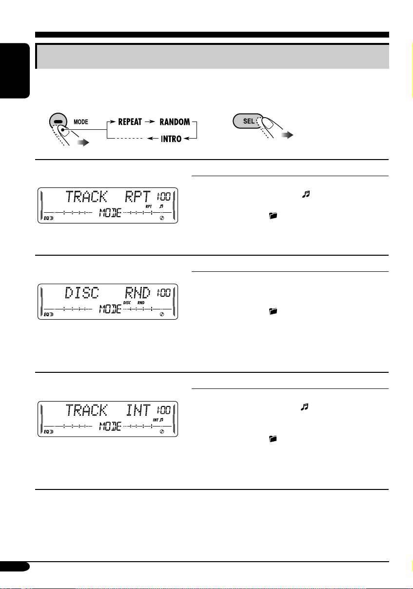
Selecting the playback modes
You can use only one of the following playback modes at a time.
ENGLISH
Select your desired playback mode.
1 2
Repeat play
Ex.: When “TRACK RPT” is selected
Random play
Ex.: When “DISC RND” is selected
Intro scan
Ex.: When “TRACK INT” is selected
Mode Plays repeatedly
TRACK RPT : The current track.
• RPT and
FOLDER RPT*
•
DISC RPT*
1
: All tracks of the current folder.
and RPT light up.
2
: All tracks of the current disc.
light up.
• DISC and RPT light up.
REPEAT OFF : Cancels.
Mode Plays at random
FOLDER RND*1: All tracks of the current folder,
then tracks of the next folder and so
on.
•
DISC RND : All tracks of the current disc.
• DISC and RND light up.
MAG RND*
2
• RND and MAG light up.
RANDOM OFF : Cancels.
Mode
TRACK INT : All tracks of the current disc.
• INT and
FOLDER INT*
•
DISC INT*
• DISC and INT light up.
INTRO OFF : Cancels.
2
and RND light up.
: All tracks of the inserted discs.
Plays the beginning 15 seconds of...
1
: The first track of every folder of
the current disc.
and INT light up.
: The first tracks of the inserted
discs.
light up.
1
*
Only while playing an MP3 disc or WMA disc.
2
*
Only while playing discs in the CD changer.
16
Page 77

Tape operations
Playing a tape
Playback starts automatically. When one
side of the tape reaches its end during play,
the other side of the tape automatically
starts playing. (Auto Reverse)
To change the playback direction
FWD PLAY
(Forward play)
To stop play and eject the cassette
The source changes to the last
selected source.
REV PLAY
(Reverse play)
Finding the beginning of a tune
Multi Music Scan (MMS) allows you to
automatically start playback from the beginning
of a specified tune.
Specify the tune you want to locate
(how many tunes ahead of or before the
current tune)
When the beginning
of the specified tune is
located, playback starts
automatically.
3
*
Goes back to the beginning of the current
tune.
Other convenient tape functions
1
ENGLISH
To fast-forward or rewind a tape
When the tape reaches its
end while fast-forwarding,
the tape direction will change
automatically.
To stop fast-forwarding or rewinding, press
the PROG button.
Prohibiting tape ejection
You can lock a tape in the loading slot.
To cancel the prohibition, repeat the same
procedure.
2
• To turn on or off Dolby B NR*
( lights up on the display)
• To skip blank portions on the tape
( lights up on the display)
• To play the current tune repeatedly
( lights up on the display)
*4 Manufactured under license from Dolby
Laboratories. “Dolby” and the doubleD symbol are trademarks of Dolby
Laboratories.
4
17
Page 78

Sound adjustments
Selecting preset sound modes
(EQ: equalizer)
ENGLISH
You can select a preset sound mode suitable to
the music genre.
~
Ÿ
FLAT O Hard Rock O R & B O
POP O JAZZ O DanceMusic O
Country O Reggae O Classic O
USER 1 O USER 2 O USER 3 O
(back to the beginning)
To select the sound mode directly
You can select the sound mode directly using
the remote controller.
Adjusting the sound
You can adjust the sound characteristics to your
preference.
1
2
Indication Range
1
FADER*
Adjust the front and rear
speaker balance.
BAL (balance)
Adjust the left and right
speaker balance.
LOUD
(loudness)
Boost low and high
frequencies to produce a
well-balanced sound at low
volume level.
VOLUME*
Adjust the volume.
*1 If you are using a two-speaker system, set
*
*
2
the fader level to “00.”
2
Normally the control dial works as the
volume control. So you do not have to select
“VOLUME” to adjust the volume level.
3
Depending on the amplifier gain control
setting. (See page 21 for details.)
R06 (Rear only)
to
F06 (Front only)
L06 (Left only)
to
R06 (Right only)
LOUD ON
LOUD OFF
00 (min.) to
30 or 50 (max.)*
3
18
Page 79

Storing your own sound
adjustments
4 Adjust the selected sound elements
while the indication on step 3 is
shown.
You can adjust the sound modes and store your
own adjustments in memory.
1
2 Select one of the sound mode to
adjust.
Ex.: When “JAZZ” is selected
3 Select the sound elements to adjust
while the selected sound mode is
shown.
Indication
LEVEL –06
(min.) to
+06
(max.)
FREQ 60Hz
80Hz
100Hz
120Hz
WIDTH 1 (min.)
to
4 (max.)
Preset values
LOW MID HIGH
–06
(min.) to
+06
(max.)
1 (min.)
to
2 (max.)
–06
(min.) to
+06
(max.)
8kHz
10kHz
12kHz
15kHz
5 Repeat steps 3 and 4 to set (or
adjust) the other sound elements.
6 Select one of the user sound modes
(USER 1, USER 2, USER 3).
ENGLISH
LOW LEVEL O LOW FREQ. O
LOW WIDTH O MID LEVEL O
MID WIDTH O HIGH LEVEL O
HIGH FREQ. O (back to the
beginning)
• (LOW, MID, HIGH) LEVEL:
Adjust the enhancement level.
• (LOW, HIGH) FREQ:
Select the center frequency to adjust.
• (LOW, MID) WIDTH :
Select the band width level.
7 Store the adjustments.
“MEMORY” appears for a
while.
19
Page 80

General settings — PSM
Basic procedure
3 Adjust the PSM item selected.
You can change PSM (Preferred Setting Mode)
items listed in the table that follows.
ENGLISH
1
4 Repeat steps 2 and 3 to adjust the
2 Select a PSM item.
5 Finish the procedure.
Indications Selectable settings, [reference page]
DEMO MODE
Display
demonstration
CLOCK HOUR
Hour adjustment
CLOCK MIN
Minute adjustment
CLOCK DISP
Clock display
LEVELMETER
Audio level meter
DEMO ON : [Initial]; Display demonstration will be activated
DEMO OFF : Cancels.
1 – 12, [8]
[Initial: 1 (1:00)]
00 – 59, [8]
[Initial: 00 (1:00)]
CLOCK ON : Clock time is shown on the display at all times even
CLOCK OFF : [Initial];
You can select one of the four different level meter patterns or a
demonstration of all the patterns.
LEVEL ALL [Initial] O LEVEL 1 O LEVEL 2 O LEVEL 3 O
LEVEL 4 O LEVEL OFF (canceled) O (back to the beginning)
LEVEL ALL : Demonstrates all the level meter patterns, each for
LEVEL 1 LEVEL 2
automatically if no operation is done for about
20 seconds, [8].
when the unit is turned off.
on
. If the unit is turned off,
the clock time for about 5 seconds.
about 20 seconds.
other PSM items if necessary.
Clock time is shown
when the unit is turned
pressing DISP will show
20
LEVEL 3 LEVEL 4
Page 81

Indications Selectable settings, [reference page]
DIMMER
Dimmer
CONTRAST
Display contrast
TEL
Telephone muting
SCROLL*
1
Scroll
EXT INPUT*
2
External input
AUX ADJUST
Auxiliary input
level adjustment
TAG DISP
Tag display
AMP GAIN
Amplifier gain
control
IF FILTER
IF filter
1
*
Some characters or symbols will not be shown correctly (or will be blanked) on the display.
2
*
Cannot be selected if the source is “CD-CH” or “EXT.”
AUTO : [Initial]; Dims the display when you turn on the
headlights.
ON : Activates dimmer.
OFF : Cancels.
1 – 10 : Adjust the display contrast to make the display indications
clear and legible.
[Initial: 5]
MUTING1/MUTING2: Select either one which mutes the sounds while
using the cellular phone.
OFF: [Initial]; Cancels.
ONCE : [Initial]; Scrolls the disc information once.
AUTO :
Repeats scrolling (5-second intervals in between).
OFF : Cancels.
• Pressing DISP for more than one second can scroll the display regardless
of the setting.
CHANGER : [Initial]; To use a JVC CD changer [13], an Apple iPod,
or a JVC D. player [22].
EXT INPUT : To use another external component, [22].
AUX ADJ 00 – AUX ADJ 05: Adjust the auxiliary input level
accordingly, to avoid the sudden increase of the output
level when changing the source from external component
connected to the AUX input jack on the control panel.
[Initial: AUX ADJ 00]
TAG ON : [Initial]; Shows the ID3 tag while playing MP3/WMA
tracks, [15].
TAG OFF : Cancels.
You can change the maximum volume level of this unit.
LOW PWR : VOLUME 00 – VOLUME 30 (Select this if the
maximum power of the speaker is less than 50 W to avoid
damaging the speaker.)
HIGH PWR : [Initial]; VOLUME 00 – VOLUME 50
AUTO : [Initial]; Increases the tuner selectivity to reduce noise
interference between the stations. (Stereo effect will also
be lost.)
WIDE : Subject to noise interference from adjacent stations, but
sound quality will not be degraded and will retain the
stereo effect.
ENGLISH
21
Page 82

External component operations
This unit is ready for any Apple iPod® or
JVC D. player control interface.
• For details, refer also to the manual
supplied with the interface adapter
ENGLISH
®
for iPod
KS-PD500.
—KS-PD100 or D. player—
Playing an external component
You can connect an external component to....
• CD changer jack on the rear using:
– Line Input Adapter—KS-U57 (not
supplied) or AUX Input Adapter—KS-U58
(not supplied) for any other components
(except iPod or D. player).
– Interface adapter for iPod
(not supplied) for controlling iPod.
– D. player interface adapter—KS-PD500
(not supplied) for controlling D. player.
• AUX (auxiliary) input jack on the control
panel.
For connection, see Installation/Connection
Manual (separate volume).
®
—KS-PD100
~ For selecting the external
component connected to....
• AUX input jack
• CD changer jack on the rear
using KS-U57 or KS-U58
If “EXT” does not appear, see page
21 and select the external input
(EXT INPUT).
• CD changer jack on the rear
using interface adapter for iPod
—KS-PD100 or for D. player—
KS-PD500
Ÿ Turn on the connected component
and start playing the source.
! Adjust the volume.
⁄ Adjust the sound as you want.
(See pages 18 and 19.)
22
Page 83

Maintenance
Handling discs
Moisture condensation
Moisture may condense on the lens inside the
CD player in the following cases:
• After starting the heater in the car.
• If it becomes very humid inside the car.
Should this occur, the CD player may
malfunction. In this case, eject the disc and
leave the unit turned on for a few hours until the
moisture evaporates.
How to handle discs
When removing a disc from
its case, press down the center
holder of the case and lift the
disc out, holding it by the edges.
• Always hold the disc by the
edges. Do not touch its recording surface.
When storing a disc into its case, gently insert
the disc around the center holder (with the
printed surface facing up).
• Make sure to store discs into the cases after
use.
Center holder
Do not use the following discs:
Warped
disc
Sticker
Disc
Handling cassettes
To clean the head
ENGLISH
Sticker
residue
Stick-on
label
To keep discs clean
A dirty disc may not play correctly.
If a disc does become dirty, wipe
it with a soft cloth in a straight line
from center to edge.
• Do not use any solvent (for example,
conventional record cleaner, spray, thinner,
benzine, etc.) to clean discs.
To play new discs
New discs may have some rough
spots around the inner and outer
edges. If such a disc is used, this
unit may reject the disc.
To remove these rough spots, rub the edges
with a pencil or ball-point pen, etc.
• Clean the heads after every 10 hours of use
using a wet-type head cleaning tape (available
at an audio store).
When the head becomes dirty, you may
realize the following symptoms:
– Sound quality is reduced.
– Sound level decreases.
– Sound drops out.
• Do not touch the highly-polished head with
any metallic or magnetic tools.
To keep the tape clean
• Always store the cassettes in their storage
cases after use.
• Do not store cassettes in the following places:
– Subject to direct sunlight
– With high humidity
– At extremely hot temperatures
23
Page 84

More about this unit
Basic operations
Turning on the power
• By pressing the source buttons on the unit,
you can also turn on the power. If the source
ENGLISH
is ready, playback also starts.
Turning off the power
• If you turn off the ignition key without
turning off this unit, the unit will
automatically turn on when you turn on the
ignition key next time. If the last selected
source is ready for playback (ex. a disc
or a tape is in the unit), playback starts
automatically.
• If you turn off the power while listening to a
disc, disc play will start from where playback
has been stopped previously, next time you
turn on the power.
Selecting the sources
• When no disc or cassette is loaded in the unit,
“CD” or “TAPE” cannot be selected.
• Without connecting to the CD changer,
“CD-CH” cannot be selected.
Tuner operations
Storing stations in memory
• During SSM search...
– All previously stored stations are erased and
stations are stored newly.
– Received stations are preset in No. 1 (lowest
frequency) to No. 6 (highest frequency).
– When SSM is over, the station stored in
No. 1 will be automatically tuned in.
• When storing a station manually, a previously
preset station is erased when a new station is
stored in the same preset number.
Disc operations
Caution for DualDisc playback
• The Non-DVD side of a “DualDisc” does
not comply with the “Compact Disc Digital
Audio” standard. Therefore, the use of NonDVD side of a DualDisc on this product may
not be recommended.
General
• MP3 and WMA (Windows Media® Audio)
“tracks” (words “file” and “track” are used
interchangeably) are recorded in “folders.”
• This unit has been designed to reproduce
CDs/CD Texts, and CD-Rs (Recordable)/
CD-RWs (Rewritable) in audio CD (CD-DA),
MP3 and WMA format.
• When a disc has been loaded, selecting “CD”
for the playback source starts disc play.
Inserting a disc
• When a disc is inserted upside down, the disc
automatically ejects and the unit starts playing
the last selected source.
• Do not insert 8 cm discs (single CD) and
unusual shape discs (heart, flower, etc.) into
the loading slot.
Playing a disc
• While fast-forwarding or reversing on an MP3
or WMA disc, you can only hear intermittent
sounds.
Playing a CD-R or CD-RW
• Use only “finalized” CD-Rs or CD-RWs.
• This unit can play back only the files of the
same type which is first detected if a disc
includes both audio CD (CD-DA) files and
MP3/WMA files.
• This unit can play back multi-session discs;
however, unclosed sessions will be skipped
while playing.
24
Page 85

• Some CD-Rs or CD-RWs may not play
back on this unit because of their disc
characteristics, and for the following causes:
– Discs are dirty or scratched.
– Moisture condensation occurs on the lens
inside the unit.
– The pickup lens inside the unit is dirty.
– CD-R/CD-RW on which the files are
written with “Packet Write” method.
– There are improper recording conditions
(missing data, etc.) or media conditions
(stain, scratch, warp, etc.).
• CD-RWs may require a longer readout time
since the reflectance of CD-RWs is lower
than that of regular CDs.
• Do not use the following CD-Rs or CD-RWs:
– Discs with stickers, labels, or protective seal
stuck to the surface.
– Discs on which labels can be directly
printed by an ink jet printer.
Using these discs under high temperatures
or high humidity may cause malfunctions or
damages to the unit.
Playing an MP3/WMA disc
• This unit can play back MP3/WMA files
with the extension code <.mp3> or <.wma>
(regardless of the letter case—upper/lower).
• This unit can show the names of albums,
artists (performer), and ID3 Tag (Version 1.0,
1.1, 2.2, 2.3, or 2.4) for MP3 files and for
WMA files.
• This unit can display only one-byte
characters. No other characters can be
correctly displayed (see page 11).
• This unit can play back MP3/WMA files
meeting the conditions below:
– Bit rate: 8 kbps — 320 kbps
– Sampling frequency:
48 kHz, 44.1 kHz, 32 kHz (for MPEG-1)
24 kHz, 22.05 kHz, 16 kHz (for MPEG-2)
48 kHz, 44.1 kHz, 32 kHz (for WMA)
– Disc format: ISO 9660 Level 1/ Level 2,
Romeo, Joliet, Windows long file name
• The maximum number of characters for file/
folder names vary among the disc format used
(includes 4 extension characters—<.mp3> or
<.wma>).
– ISO 9660 Level 1: up to 12 characters
– ISO 9660 Level 2: up to 31 characters
– Romeo*: up to 128 (72) characters
– Joliet*: up to 64 (36) characters
– Windows long file name*: up to 128 (72)
characters
* The parenthetic figure is the maximum
number of characters for file/folder names
in case the total number of files and folders
is 313 or more.
• This unit can recognize the total of 512 files,
of 200 folders, and of 8 hierarchies.
• This unit can play back the files recorded in
VBR (variable bit rate).
The files recorded in VBR have a discrepancy
in elapsed time display, and do not show the
actual elapsed time. This difference becomes
noticeable especially after performing the
search function.
• This unit cannot play back the following files:
– MP3 files encoded with MP3i and
MP3 PRO format.
– MP3 files encoded in an unappropriated
format.
– MP3 files encoded with Layer 1/2.
– WMA files encoded with lossless,
professional, and voice format.
– WMA files which are not based upon
Windows Media
– WMA files copy-protected with DRM.
– Files which have the data such as WAVE,
ATRAC3, etc.
• The search function works but search speed is
not constant.
®
Audio.
ENGLISH
To be continued....
25
Page 86

Changing the source
• If you change the source, playback also stops
(without ejecting the disc).
Next time you select “CD” or “CD-CH” for
ENGLISH
the playback source, disc play starts from
where it has been stopped previously.
Ejecting a disc
• If the ejected disc is not removed within
15 seconds, the disc is automatically inserted
again into the loading slot to protect it from
dust. (Disc will not play this time.)
Tape operations
Playing a tape
• While locating a specified tune:
– If the tape is rewound to its beginning,
playback starts from the beginning of that
side.
– If the tape is fast-forwarded to the end, it is
reversed and played from the beginning of
the other side.
• In the following cases, Multi Music Scan
(MMS), Blank Skip, and Repeat Play may not
operate correctly:
– Tapes with tunes having long pianissimo
passages (very quiet parts) or non-recorded
portions.
– Tapes with short non-recorded sections.
– Tapes with high level noise or humming
between tunes.
– The Dolby NR setting does not match. For
example, if the tape is recorded with the
Dolby C NR.
• Do not use the following tape:
– Dirty or dusty tapes.
– Cassette with peeling labels.
– Loose tape which may become entangled
with the mechanism.
Changing the source
• If you change the source, playback also stops
(without ejecting the cassette).
Ignition key-off release
• When you turn off the ignition key with
a cassette in the compartment, the unit
automatically releases the tape from its head.
General settings—PSM
• If you change the “TAG DISP” setting from
“TAG OFF” to “TAG ON” while playing
MP3/WMA file, the tag display will be
activated when the next file starts playing.
• If you change the “AMP GAIN” setting
from “HIGH PWR” to “LOW PWR”
while the volume level is set higher than
“VOLUME 30,” the unit automatically
changes the volume level to “VOLUME 30.”
Other main functions
• If you try to assign a title to the 31st station
frequency, “NAME FULL” flashes. Delete
unwanted titles before assignment.
Available characters on the display
These characters (including the Roman
alphabets) can use to show other information
such as disc title/performer on the display.
Russian letters
Upper case
Lower case
Numbers and symbols
26
Page 87

Troubleshooting
What appears to be trouble is not always serious. Check the following points before calling a service
center.
Symptoms Remedies/Causes
• Sound cannot be heard from the
speakers.
General
• The unit does not work at all. Reset the unit (see page 2).
• SSM automatic presetting does not
work.
FM/AM
• Static noise while listening to the radio. Connect the aerial firmly.
• Disc cannot be played back. Insert the disc correctly.
• CD-R/CD-RW cannot be played back.
• Tracks on the CD-R/CD-RW cannot be
skipped.
• Disc can be neither played back nor
ejected.
Disc playback
• Disc sound is sometimes interrupted. • Stop playback while driving on rough roads.
• “NO DISC” appears on the display. Insert a correct disc into the loading slot.
• Disc cannot be played back. • Use a disc with MP3/WMA tracks recorded in
• Adjust the volume to the optimum level.
• Check the cords and connections.
Store stations manually.
• Insert a finalized CD-R/CD-RW.
•
Finalize the CD-R/CD-RW with the component
which you used for recording.
• Unlock the disc (see page 15).
• Eject the disc forcibly (see page 2).
• Use an unscratched disc.
• Check the cords and connections.
the format compliant with ISO 9660 Level 1,
Level 2, Romeo, or Joliet.
• Add the extension code <.mp3> or <.wma> to
the file names.
ENGLISH
• Noise is generated. Skip to another track or change the disc. (Do not
add the extension code <.mp3> or <.wma> to
MP3/WMA playback
• A longer readout time is required
(“CHECK” keeps flashing on the
display).
non-MP3 or WMA tracks.)
Do not use too many hierarchies and folders.
To be continued....
27
Page 88

Symptoms Remedies/Causes
• Tracks do not play back in the order
ENGLISH
• Elapsed playing time is not correct. This sometimes occurs during play. This is caused
• “NO FILES” appears on the display. Insert a disc that contains MP3/WMA tracks.
MP3/WMA playback
• Correct characters are not displayed
• A cassette cannot be inserted. Insert the cassette with the exposed tape facing
• Cassette can be neither played back nor
• “NO TAPE” appears on the display. Insert a cassette correctly.
Tape playback
• Cassette tapes become hot. This is not a malfunction.
• Tape sound is at very low level and
• “NO DISC” appears on the display.
• “NO MAG” appears on the display. Insert the magazine.
• “RESET 8” appears on the display. Connect this unit and the CD changer correctly
CD changer
• “RESET 1” – “RESET 7” appears on
you have intended them to play.
(e.g. album name).
ejected.
sound quality is degraded.
the display.
Playback order is determined when the files are
recorded.
by how the tracks are recorded on the disc.
This unit can only display alphabets (upper/lower
case), numbers, and a limited number of symbols.
right.
Unlock the cassette (see page 17).
Clean the tape head using a head cleaning tape.
Insert a disc into the magazine.
and press the reset button of the CD changer.
Press the reset button of the CD changer.
• The CD changer does not work at all. Reset the unit (see page 2).
• Microsoft and Windows Media are either registered trademarks or trademarks of Microsoft
Corporation in the United States and/or other countries.
28
Page 89

Specifications
AUDIO AMPLIFIER SECTION
Maximum Power Output:
Front: 50 W per channel
Rear: 50 W per channel
Continuous Power Output (RMS):
Front: 19 W per channel into 4 Ω, 40 Hz
to 20 000 Hz at no more than 0.8%
total harmonic distortion.
Rear: 19 W per channel into 4 Ω, 40 Hz
to 20 000 Hz at no more than 0.8%
total harmonic distortion.
Load Impedance: 4 Ω (4 Ω to 8 Ω allowance)
Equalizer Control Range:
Low: ±12 dB (60 Hz, 80 Hz, 100 Hz, 120 Hz)
Mid: ±12 dB
High: ±12 dB (8 kHz, 10 kHz, 12 kHz, 15 kHz)
Frequency Response: 40 Hz to 20 000 Hz
Signal-to-Noise Ratio: 70 dB
Line-Out Level/Impedance:
2.0 V/20 kΩ load (full scale)
Output Impedance: 1 kΩ
Other terminals: CD changer, AUX (auxiliary)
input jack
TUNER SECTION
Frequency Range:
FM: 87.5 MHz to 108.0 MHz
AM: 531 kHz to 1 602 kHz
[FM Tuner]
Usable Sensitivity: 11.3 dBf (1.0 µV/75 Ω)
50 dB Quieting Sensitivity:
16.3 dBf (1.8 µV/75 Ω)
Alternate Channel Selectivity (400 kHz): 65 dB
Frequency Response: 40 Hz to 15 000 Hz
Stereo Separation: 30 dB
Capture Ratio: 1.5 dB
[AM Tuner]
Sensitivity: 20 µV
Selectivity: 35 dB
CD PLAYER SECTION
Type: Compact disc player
Signal Detection System: Non-contact optical
pickup (semiconductor laser)
Number of Channels: 2 channels (stereo)
Frequency Response: 5 Hz to 20 000 Hz
Dynamic Range: 96 dB
Signal-to-Noise Ratio: 98 dB
Wow and Flutter: Less than measurable limit
MP3 Decoding Format:
MPEG1/2 Audio Layer 3
Max. Bit Rate: 320 kbps
WMA (Windows Media
Format:
Max. Bit Rate: 192 kbps
®
Audio) Decoding
CASSETTE DECK SECTION
Wow and Flutter: 0.1 % (WRMS)
Fast-Wind Time: 100 sec. (C-60)
Frequency Response: 30 Hz to 16 000 Hz
(Normal tape)
Signal-to-Noise Ratio: (Normal tape)
Dolby B NR ON: 65 dB
Dolby B NR OFF: 56 dB
Stereo Separation: 40 dB
GENERAL
Power Requirement:
Operating Voltage:
DC 14.4 V (11 V to 16 V allowance)
Grounding System: Negative ground
Allowable Operating Temperature:
0°C to +40°C
Dimensions (W × H × D):
Installation Size (approx.):
178 mm × 100 mm × 158 mm
Set Size (approx.):
178 mm × 100 mm × 175 mm
Mass (approx.):
2.3 kg (excluding accessories)
ENGLISH
Design and specifications are subject to change
without notice.
29
Page 90

Having TROUBLE with operation?
Please reset your unit
Refer to page of How to reset your unit
Затруднения при эксплуатации?
Пожалуйста, перезагрузите Ваше устройство
Для получения информации о перезагрузке Вашего устройства
обратитесь на соответствующую страницу
EN, RU
© 2005 Victor Company of Japan, Limited
1005DTSMDTJEIN
Page 91

KW-XC407
Installation/Connection Manual
Руководство по установке/подключению
GET0329-002A
[EE]
ENGLISH
This unit is designed to operate on 12 V DC, NEGATIVE ground electrical systems. If your
vehicle does not have this system, a voltage inverter is required, which can be purchased at
JVC IN-CAR ENTERTAINMENT dealers.
Parts list for installation and connection
The following parts are provided for this unit.
After checking them, please set them correctly.
Flat countersunk screws (M5 x 8 mm)
Болт с плоской потайной головкой (M5 x 8 mm)
1005DTSMDTJEIN
EN, RU
© 2005 Victor Company of Japan, Limited
РУССКИЙ
Это устройство разработано для эксплуатации на 12 В постоянного напряжения с
минусом на массе. Если Ваш автомобиль не имеет этой системы, требуется инвертор
напряжения, который может быть приобретен у дилера автомобилнего специалиста
JVC IN-CAR ENTERTAINMENT.
Список деталей для установки и подключения
Следующие детали поставлены в комплекте с устройством.
После проверки комплектации, пожалуйста, установите их правильно.
Power cord
Binding screws (M5 x 8 mm)
Зажимной болт (M5 x 8 mm)
Кабель питания
When installating the unit in a Nissan car
Установка устройства в автомобиле марки Nissan
Fix the supplied plate as illustrated.
Закрепите прилагаемую пластину, как показано на
рисунке.
PRECAUTIONS on power supply and speaker connections:
• DO NOT connect the speaker leads of the power cord to the car battery; otherwise,
the unit will be seriously damaged.
• BEFORE connecting the speaker leads of the power cord to the speakers, check the
speaker wiring in your car.
Battery
Бaтapeйкa
Remote controller
диcтaнциoннoго yпpaвлeния
Plate for use with a Nissan car
Пластина для автомобилей марки
Nissan
Plate for use with a Nissan car
Пластина для автомобилей марки
Nissan
ПРЕДОСТЕРЕЖЕНИЯ по питанию и подключению громкоговорителей:
• НЕ подключайте провода громкоговорителей к аккумулятору автомобиля,
иначе устройство будет повреждено.
• ПЕРЕД подключением проводов громкоговорителей к кабелю питания
громкоговорителя проверьте схему соединений громкоговорителей в Вашем
автомобиле.
TROUBLESHOOTING
• The fuse blows.
* Are the red and black leads connected correctly?
• Power cannot be turned on.
* Is the yellow lead connected?
• No sound from the speakers.
* Is the speaker output lead short-circuited?
• Sound is distorted.
* Is the speaker output lead grounded?
* Are the “–” terminals of L and R speakers grounded in common?
• Noise interfere with sounds.
* Is the rear ground terminal connected to the car’s chassis using shorter and thicker cords?
• Unit becomes hot.
* Is the speaker output lead grounded?
* Are the “–” terminals of L and R speakers grounded in common?
• This unit does not work at all.
* Have you reset your unit?
BЫЯВЛЕНИЕ НЕИСПРАВНОСТЕЙ
• Сработал предохранитель.
* Правильно ли подключены черный и красный провода?
• Питание не включается.
* Подключен ли желтый провод?
• Звук не выводится через громкоговорители.
* Нет ли короткого замыкания на кабеле выхода громкоговорителей?
• Звук искажен.
* Заземлен ли провод выхода громкоговорителей?
* Заземлены ли разъемы “–” правого (R) и левого (L) громкоговорителей?
• Шум мешает звучанию.
* Соединен ли находящийся сзади зажим заземления с шасси автомобиля с помощью
более короткого и тонкого шнуров?
• Устройство нагревается.
* Заземлен ли провод выхода громкоговорителей?
* Заземлены ли разъемы “–” правого (R) и левого (L) громкоговорителей?
• Приемник не работает.
* Выполнена ли перенастройка приемника?
1
Page 92

INSTALLATION (IN-DASH MOUNTING)
УСТАНОВКА (УСТАНОВКА В ПРИБОРНУЮ ПАНЕЛЬ)
The following illustration shows a typical installation. However, you should make adjustments
corresponding to your specific car. In this case consult the manual included with the installation
kit (option).
In some case, depending of the type and the model of your car, it is not possible to install the
unit into the center console.
If you have any questions or require information regarding installation kits, consult your
JVC IN-CAR ENTERTAINMENT or a company supplying kits.
• If you are not sure how to install this unit correctly, have it installed by a qualified technician.
Before installing the unit
• When mounting the unit, be sure to use the screws provided, as instructed. If other screws are
used, there is a possibility that parts could become loose or damaged.
• When tightening screws or bolts be careful not to pinch any connection cord.
1 Remove the audio system originally installed together with the mounting brackets.
Note: Be sure to keep all the screws and parts removed from your car for future use.
2 Attach the mounting brackets (removed from the car), to this unit (see below).
3 Connect the wires (see diagram ).
4 Fix this unit to the car using the screws removed in step 1.
• See “Caution” below.
На следующей иллюстрации показана типовая установка. Однако возможны
дополнительные регулировки в соответствии с определенным автомобилем. В этом
случае обратитесь к руководству, включенному в монтажный комплект (поставляется
отдельно).
В некоторых случаях, в зависимости от типа и модели автомобиля, устройство можно
установить на центральной панели.
При появлении вопросов или при необходимости получения информации относительно
монтажных комплектов обратитесь к поставщику автомобильных аудиосистем компании
JVC IN-CAR ENTERTAINMENT или в компанию, поставляющую монтажные комплекты.
• Если Вы не знаете точно, как следует устанавливать это устройство, обратитесь к
квалифицированному специалисту.
Перед установкой устройства
• При установке устройства используйте только прилагаемые болты в соответствии
с инструкцией. В случае использования других болтов существует вероятность, что
детали могут быть потеряны или повреждены.
• Аккуратно затягивайте болты, чтобы не пережать соединительные кабели.
1 Извлеките первоначально установленную аудиосистему вместе с крепежными
скобами.
Примечание: Убедитесь в том, что все болты и детали системы извлечены из
автомобиля для будущего использования.
2 Прикрепите крепежные скобы, извлеченные из автомобиля, к данному устройству
(см. ниже).
3 Подключите провода (см. схему ).
4 Закрепите данное устройство в автомобиле с помощью болтов, извлеченных в
действии 1.
• См. предостережение ниже.
The following example shown is for installation in a Toyota car.
For more details, consult your JVC IN-CAR ENTERTAINMENT dealer.
Securely connect the ground wire to the metal body
of the car using the screw originally fixed to the metal
body of the car.
Плотно прикрепите заземляющий провод к
металлическим частям автомобиля с помощью
уже имеющихся там болтов.
Mounting bracket removed from the car
Извлеченные из автомобиля
крепежные скобы
Screws supplied for this unit
Болты, поставляемые с
данным устройством
Screws supplied for this unit:
Болты, поставляемые с данным устройством:
Select the proper screw type, fitting to your car.
Подберите подходящий для автомобиля тип болта.
На следующем рисунке показана установка устройства в автомобиле
марки Toyota.
За более подробной информацией обратитесь к поставщику
автомобильных аудиосистем компании JVC IN-CAR ENTERTAINMENT.
Mounting bracket removed from the car
Извлеченные из автомобиля крепежные
скобы
Binding screws (M5 x 8 mm)
Зажимной болт (M5 x 8 mm)
Screws supplied for this unit
Болты, поставляемые с данным
устройством
Screw removed from the car in step 1
Болты, извлеченные из автомобиля в
автомобиля в действии 1
Flat countersunk screws (M5 x 8 mm)
Болт с плоской потайной головкой
(M5 x 8 mm)
Caution:
To install the mounting brackets to the unit, use only the supplied screws (M5 x 8 mm).
If you use any screw longer than 8 mm, the unit can be damaged.
If there is an interfering tab on the mounting bracket, bent it flat.
Если на крепежных скобах есть мешающие установке уголковые
фиксаторы, разогните их.
ELECTRICAL CONNECTIONS
To prevent short circuits, we recommend that you disconnect the battery’s negative terminal and
make all electrical connections before installing the unit.
• Be sure to ground this unit to the car’s chassis again after installation.
Notes:
• Replace the fuse with one of the specified rating. If the fuse blows frequently, consult your
JVC IN-CAR ENTERTAINMENT dealer.
• If noise is a problem...
This unit incorporates a noise filter in the power circuit. However, with some vehicles, clicking
or other unwanted noise may occur. If this happens, connect the unit’s rear ground terminal
(see connection diagram) to the car’s chassis using shorter and thicker cords, such as copper
braiding or gauge wire. If noise still persists, consult your JVC IN-CAR ENTERTAINMENT
dealer.
• It is recommended to connect to the speakers with maximum power of more than 50 W (both
at the rear and at the front, with an impedance of 4 Ω to 8 Ω). If the maximum power is less
than 50 W, change “AMP GAIN” setting to prevent the speakers from being damaged (see
page 21 of the INSTRUCTIONS).
• The heat sink becomes very hot after use. Be careful not to touch it when removing this unit.
Rear view
Вид сзади
Heat sink
Радиатор
предостережение
Для прикрепления крепежных скоб к устройству используйте только прилагаемые
болты (M5 x 8 мм). Использование любых болтов длиной более 8 мм может
привести к повреждению устройства.
Install the unit at an angle of less than 30°.
Установите устройство под углом менее 30°.
Less than 30˚
Менее 30°
ЭЛЕКТРИЧЕСКИЕ ПОДКЛЮЧЕНИЯ
Для предотвращения коротких замыканий мы рекомендуем Вам отсоединить
отрицательный разъем аккумулятора и осуществить все подключения перед установкой
устройства.
• После установки обязательно заземлите данное устройство на шасси
автомобиля.
Примечания:
• Заменяйте предохранитель другим предохранителем указанного класса. Если
предохранитель сгорает слишком часто, обратитесь к дилеру
JVC IN-CAR ENTERTAINMENT.
• При появлении сильных помех...
Это устройство оснащено фильтром помех в цепи питания. Однако в некоторых
случаях возможно появление щелчков и других нежелательных помех. В этом случае
подключите задний разъем заземления этого устройства (см. схему подключения
ниже) к шасси автомобиля при помощи более коротких и толстых проводов. Если
помехи не исчезают, обратитесь к дилеру JVC IN-CAR ENTERTAINMENT.
• Рекомендуется подключать динамики с максимальной мощностью более 50 Вт (к
задней и передней панели устройства, с полным сопротивлением от 4 Ω до 8 Ω). Если
максимальная мощность динамиков менее 50 Вт, перейдите в режим “AMP GAIN”,
чтобы предотвратить их повреждение (см. стр. 21 ИНСТРУКЦИИ ПО ЭКСПЛУАТАЦИИ).
• Радиатор во время использования сильно нагревается. Старайтесь его не трогать во
время удаления устройства.
2
Page 93

E
F
B
D
H
G
A
C
N
J
I
K
M
L
P
O
ENGLISH
РУССКИЙ
If your car is equipped with the ISO connector /
A
Если автомобиль оснащен разъемом ISO
• Connect the ISO connectors as illustrated.
• Подключите разъемы ISO, как показано на рисунке.
From the car body
От корпуса автомобиля
ISO connector of the supplied power cord
Разъем ISO шнура питания, входящего в
комплект поставки
View from the lead side
Вид со стороны выводов
For some VW/Audi or Opel (Vauxhall) automobile / Для некоторых автомобилей VW/Audi или Opel
(Vauxhall)
You may need to modify the wiring of the supplied power cord as illustrated.
• Contact your authorized car dealer before installing this unit.
Возможно, потребуется изменить схему соединений для прилагаемого шнура питания, как показано на рисунке.
• Перед установкой приемника обратитесь к авторизованному агенту по продажам автомобильных систем.
Original wiring /
Исходная схема соединений
ISO connector
Разъем ISO
Y: Yellow
Желтый
Use modified wiring
Если приемник не включается, используйте преобразованную схему
соединений 2.
R: Red
Красный
Modified wiring 1 /
Преобразованная схема соединений 1
2
if the unit does not turn on.
Modified wiring 2 /
Преобразованная схема соединений 2
Connections without using the ISO connectors / Подключение без использования разъемов ISO
B
Before connecting: Check the wiring in the vehicle carefully. Incorrect connection may cause
serious damage to this unit.
The leads of the power cord and those of the connector from the car body may be different in
color.
1 Cut the ISO connector.
2 Connect the colored leads of the power cord in the order specified in the illustration below.
3 Connect the aerial cord.
4 Finally connect the wiring harness to the unit.
To steering wheel remote controller (see diagram
К рулевому пульту дистанционного управления (см. схему
To CD changer, Apple iPod,
JVC D.player, or another external
component (see diagram
К устройству автоматической
смены компакт-дисков, Apple
iPod, проигрывателю JVC D. или
другому внешнему устройству
(см. схему )
)
Black
Черный
Перед началом подключений: Тщательно проверьте проводку в автомобиле.
Неправильное подключение может привести к серьезному повреждению устройства.
Жилы силового кабеля и жилы соединителя от кузова автомобиля могут быть разного
цвета.
1 Обрежьте разъем ISO.
2 Подсоедините цветные провода шнура питания в указанном ниже порядке.
3 Подключите кабель антенны.
4 В последнюю очередь подключите электропроводку к устройству.
)
15 A fuse
Предохранитель 15 A
Line out (see diagram )
К выходу (см. схему )
To metallic body or chassis of the car
К металлическому корпусу или шасси автомобиля
)
1
*
Not included for this unit
1
*
Не входит в комплект
Ignition switch
Переключатель зажигания
*2
Before checking the operation of this unit prior to
installation, this lead must be connected, otherwise
power cannot be turned on.
*2 Перед проверкой работы устройства
подключите этот провод, иначе питание не
включится.
2
Yellow
*
Желтый*
Red
Красный
Blue with white stripe
Синий с белой полосой
Orange with white stripe
Оранжевый с белой полосой
Brown
Коричневый
2
To a live terminal in the fuse block connecting to the car battery
(bypassing the ignition switch) (constant 12 V)
К разъему фазы в блоке предохранителя (минуя блок зажигания)
(постоянный 12 В)
Fuse block
Блок предохранителя
To an accessory terminal in the fuse block
К вспомогательному разъему в блоке предохранителя
To the remote lead of other equipment or power aerial if any (200 mA max.)
К удаленному проводу другого оборудования или антенны (макс. 200 мА)
To car light control switch
К контрольному переключателю освещения автомобиля
To cellular phone system
К системе сотового телефона
White with black stripe
Белый с черной
полосой
White
Белый
Left speaker (front)
Левый громкоговоритель
(передний)
Gray with black stripe
Серый с черной полосой
Gray
Серый
Right speaker (front)
Правый громкоговоритель
(передний)
Green with black stripe
Зеленый с черной полосо
3
Green
Зеленый
Left speaker (rear)
Левый громкоговоритель
(задний)
Purple with black stripe
Пурпурный с черной
полосой
Purple
Пурпурный
Right speaker (rear)
Правый громкоговоритель
(задний)
Page 94

C
Connecting the external amplifiers / Подключение внешних усилителей
You can connect amplifiers to upgrade your car stereo system.
• Connect the remote lead (blue with white stripe) to the remote lead of the other equipment
so that it can be controlled through this unit.
• Disconnect the speakers from this unit, connect them to the amplifier. Leave the
speaker leads of this unit unused.
Можно подключить усилители для обновления автомобильной стереосистемы.
• Подсоедините провод внешнего устройства (синий с белой полосой) к проводу
внешнего устройства другого оборудования так, чтобы им можно было управлять с
этого устройства.
• Отсоедините громкоговорители от данного устройства, подключите их
к усилителю. Оставьте провода громкоговорителей данного устройства
неиспользованными.
Rear speakers
Задние
громкоговорители
JVC Amplifier
JVC-усилитель
Front speakers
Передние
громкоговорители
JVC Amplifier
JVC-усилитель
Remote lead
Провод внешнего устройства
Remote lead (Blue with white stripe)
Провод внешнего устройства (Синий с белой полосой)
Y-connector (not supplied for this unit)
Разъем Y (не входит в комплект)
To the remote lead of other equipment or power aerial if any
К удаленному проводу другого оборудования или антенны
Front speakers (see diagram
Передние громкоговорители (см. схему )
Rear speakers
Задние громкоговорители
)
3
*
Firmly attach the ground wire to the
metallic body or to the chassis of the
car—to the place uncoated with paint (if
5
*
Cut the rear speaker leads of the
car’s ISO connector and connect
them to the amplifier.
5
*
Отрежьте провода задних
громкоговорителей разъема
ISO и подсоеди ните их к
усилителю.
coated with paint, remove the paint before
attaching the wire). Failure to do so may
cause damage to the unit.
3
*
Плотно прикрепите заземляющий
провод к металлическому кузову
или шасси автомобиля—в месте, не
покрытом краской (если оно покрыто
краской, удалите краску перед тем, как
прикреплять провод). Невыполнение
этого требования может привести к
повреждению данного устройства.
D
Connecting the external components / Подключение внешних устройств
• Set “EXT INPUT” to “CHANGER” (see page 21 of the INSTRUCTIONS). /
ЭКСПЛУАТАЦИИ).
Для параметра “EXT INPUT” установите значение “CHANGER” (см. стр. 21 ИНСТРУКЦИИ ПО
CD Changer / Проигрыватель нескольких компакт-дисков
CD changer jack
Разъем
устройства
автоматической
смены компактдисков
CAUTION / ПРЕДОСТЕРЕЖЕНИЕ
:
• Before connecting the CD changer, make sure the unit is turned off.
• Перед подключением устройства автоматической смены
компакт-дисков, что приемник отключен.
6
*
Connecting cord supplied for your CD changer
6
*
Подключение кабеля, входящего в комплект поставки
устройства автоматической смены компакт-дисков
JVC CD changer
Проигрыватель нескольких
компакт-дисков JVC
4
*
Signal cord (not supplied for this unit)
4
*
Кабель сигнала (не входит в комплект)
Apple iPod® or JVC D. player / проигрыватель Apple iPod® или JVC D.
You can connect an iPod or a D. player using an interface adapter (not supplied)—KS-PD100 (for
iPod) or KS-PD500 (for D. player).
Можно подключить проигрыватель iPod или D. с помощью интерфейсного адаптера (не входит
в комплект поставки)—KS-PD100 (для iPod) или KS-PD500 (для проигрывателя D.).
iPod is a trademark of Apple Computer, Inc.,
registered in the U.S. and other countries.
iPod является торговой маркой Apple Computer,
Inc., зарегистрированной в США и других
странах.
CD changer jack
Разъем устройства
автоматической
смены компактдисков
Apple iPod
(separately purchased)
Apple iPod
(продается отдельно)
JVC D. player
(separately purchased)
Проигрыватель JVC D.
(продается отдельно)
• Set “EXT INPUT” to “EXT INPUT” (see page 21 of the INSTRUCTIONS). /
ЭКСПЛУАТАЦИИ).
Для параметра “EXT INPUT” установите значение “EXT INPUT” (см. стр. 21 ИНСТРУКЦИИ ПО
External Component / Внешнее устройство
You can connect an external component
using a line input adapter, KS-U57 (not
supplied) or AUX input adapter, KS-U58
(not supplied).
Можно подключить внешнее устройство
с помощью линейного адаптера
входа KS-U57 (не входят в комплект
поставки) или адаптера входа для
подключения внешних устройств
(AUX) KS-U58 (не входят в комплект
поставки).
Connecting to the steering wheel remote controller / Подключение к рулевому пульту дистанционного управления
E
If your car is equipped with the steering wheel remote controller, you can operate this unit
using the controller. To do it, a JVC’s OE remote adapter (not supplied) which matches with
your car is required. Consult your JVC IN-CAR ENTERTAINMENT dealer for details.
Если автомобиль оборудован рулевым пультом дистанционного управления, его можно
использовать для управления данным устройством. Для этого необходим адаптер
рулевого пульта дистанционного управления JVC OE (не поставляется), подходящий
для Вашего автомобиля. За более подробной информацией обратитесь к поставщику
автомобильных аудиосистем компании JVC IN-CAR ENTERTAINMENT.
CD changer jack
Разъем устройства
автоматической
смены компакт-
дисков
External component
Внешнее устройство
3.5 mm stereo mini plug
Мини-разъем стерео-3,5
Steering wheel remote input
Вход рулевого пульта
дистанционного управления
Steering wheel remote controller (equipped in the car)
Рулевой пульт дистанционного управления
(устанавливаемый в автомобиле)
External component
Внешнее устройство
7
*
Signal cord (not supplied for this unit)
7
*
Кабель сигнала (не входит в комплект)
OE remote adapter (not supplied)
Aдаптер рулевого пульта дистанционного
управления OE (не поставляется)
4
Page 95

SCHEMATIC DIAGRAMS
CD/CASSETTE RECEIVER
KW-XC400,KW-XC407
CD-ROM No.SML200512
KW-XC400
KW-XC407
KW-XC400
Area suffix
J ------------- Northern America
KW-XC407
Area suffix
EE -------- Russian Federation
Lead free solder used in the board (material : Sn-Ag-Cu, melting point : 219 Centigrade)
Contents
Block diagram
Standard schematic diagrams
Printed circuit boards
COPYRIGHT 2005 Victor Company of Japan, Limited.
2-1
2-3
2-19 to 25
No.MA235SCH
2005/12
Page 96

Safety precaution
!
!
Burrs formed during molding may be left over on some parts of the chassis. Therefore,
pay attention to such burrs in the case of preforming repair of this system.
Please use enough caution not to see the beam directly or touch it in case of an
adjustment or operation check.
Page 97

< MEMO >
Page 98

Block diagram
R
/
PICK UP
LOAD/FEED
MOTOR
SPINDLE
MOTOR
REST SW
SW1,SW2
VA,VB,VE,VF
MD,LD,VREF
FOCUS+
FOCUSTRACKING+
TRACKING-
LOAD/FEED+
LOAD/FEED-
SPINDLE+
SPINDLE-
REST
SW1,SW2
CN001
CD servo control section
CN601
VA,VB
VE,VF
LD,MD
VREF
FOCUS+
FOCUSTRACKING+
TRACKINGSPINDLE+
SPINDLELOAD/FEED+
LOAD/FEED-
IC601
CD RF
RFGC,RF
RFRP,FE
SEL,TEB
RFDC
IC621
D.SERVO
SW1,SW2,REST
IOP
RWSEL
IC681
CD
DRIVER
FMO
FOO
DMO
TRO
&
DSP
CDON
LOAD
LD/FE
BUS0
BUS1
BUS2
BUS3
BUCK
CCE
DSPRST
DATA
LRCK
BCK
LRCK
BCK
IC501
CPU
SDA
SCL
MP3DA
MP3CK
IC652
MP3 DEC
SDO
IC571
24Bit DAC
PICTCLK,PICTDI
CDMUTE,CDREQ
B.DET,P.DET
CDRESET
BUSSI
BUSSO
BUSIO
/BUSIO
BUSCLK
IC503
J-BUS
BUFF
IC502
EEPROM
VOUTL
VOUTR
IC572
CD LPF
B
B
2-1
ANT
CD-CH
Main amplifier section
J1
CN902
CH-L,CH-R
TU1
FM/AM
TUNER
SCK
SI/SO
JVC BUS
IC781
TU-L
TU-R
PLLCE,PLLDO,PLLCK
PLLDI,MRC,SD/ST
SMETER,CFSEL
SDA
IC702
SCL
EEPROM
BUSINT,BUSI/O
BUSSCK,BUSSO
IC701
CPU
CDREQ,CDMUTE
CDRESET,PS2
POWER
EVOLDA
EVOLCK
RESET
SI/SO
SCK
CSTREQ
CSTMUTE
IC703
RESET
TU-L/
CH-L
Page 99

Cassette mechanism control section
T
CN403
TDI
REQ
TAPEIN
MODE
REEL
STANDBY
SUBMO+
SUBMO-
IC402
MOTOR
DRIVER
SUBMO+
BUSSI/SO
503
BUSCLK
BUS
PREQ
P.DET
A.MUTE
IC431
CPU
SUBMO-
FF
FF/REW
MSIN
HEAD SEL
IC461
J-BUS
SCK,SI/SO
CN401
CASSETTE MECHA
CN402
FWD-L,FWD-R
REW-L,REW-R
IC401
HEAD AMP
Lch
Rch
M
572
LPF
EQ
UTE
TU-L/R
CH-L/R
CD.L-CH
CD.R-CH
CN501
CN705
CD-L
CD-R
E.VOLME
IC151
AUX_L,AUX_R
TAPE-L
TAPE-R
CN803
CN802
CN702
IC802
REMOCON
REMOTE
CN801
CN701
EN851
ENCODER
VOL1
VOL2
D811 to D839
LCDRST,LCDDA
LCDSCK,LCDCE
KEY0 to KEY2
VOL1,VOL2
REMOCON
LCDILL,RESET
AUX_L
AUX_R
KEYILL
LED
to
each
block
LCD and user control keys section
S851 to S870
SW
KEY0
KEY1
KEY2
S871
RESET
OUTFL+/OUTFR+/OUTRL+/OUTRR+/-
IC901
REGULATOR
LCDDATA
LCDRESET
LCDSCK
LCDCE
RESET
POWER
CN323
IC181
AMP
LCD1
IC801
LCD
DRIVER
CN322
SEG1 to SEG62
COM1 to COM10
AUX_L
AUX_R
FRONT L+/FRONT R+/REAR L+/REAR R+/-
ACC
REMOTE
AUTO ANT
PJ801
AUX IN
J321
LINE OUT
CN901
SPK
BATT
2-2
Page 100

Standard schematic diagrams
Main amplifier section (For KW-XC400)
QAU0403-001
TU1
J1
QNB0190-001
L1
4.7u
47/10
220/10
0.01
47/10
0.01
1SS355W-X
1SS355W-X
D1
C2
C3
C4
D2
Q1
2SA1365/F/-X
D3
CN705
QGB2027M4-22S
RT1N141C-X
(SHEET 2)
0.01
C733
Q706
RT1N141C-X
0.01
0.01
Q705
RT1N441C-X
C730
C731
QGB1004K1-20
CN701
(SHEET 4)
D715
D713
D702
D703
D704
D705
D706
D707
D716
D714
CN703
QGF0501F1-06X
UDZW6.2B-X
(SHEET 4)
0.01
0.01
0.01
0.11k0.1
0.01
CN702
C723
C724
C720
C725
C722
QGB1004K1-16
R748
R749
0.01
C732
D708
C726C7C727
CD-L
CD-R
CDMUTE
Q708
RT1N141C-X
CDREQ
Q707
0
0
VDD5V
CD8V
L703
47u
POWER
CDRESET
Q704
RT1N141C-X
TEMP
KEY0
KEY1
KEY2
LCDILL
KEYILL
LCDCE
LCDSCK
LCDDA
ACC5V
RESET
REMOCON
LCDRST
AUX_R
AUX_G
0
AUX_L
D709
D710
D711
D712
R757
TAPE-L
TAPE-R
CD8V
CSTREQ
SI/SO
CSTMUTE
0.1
CSTRST
Q703
RT1N141C-X
SI/SO
SCK
Q2
2SA1365/F/-X
R1
10k
R3
10k
1k
R4
MC2838-X
R2
2.2k
GND
SCK
PS2
14V
0.1
C728
SI
SO
GND
9V
14V
LCDILL
KEYILL
ANT
POWER
CDMUTE
CDRESET
CSTMUTE
CSTRST
L702
47u
0.01
C721
Q3
RT1N141C-X
470P
C719
2SA1365/F/-X
47k
R764
47k
R777
Q702
RT1N441C-X
Q904
C715
0.01
R916
2.2k
Q905
RT1N141C-X
R770
R772
R774
R735
R736
R759
R773
R771
R719
C5
C1
C11
0.01
22
10
R5
R6
SW5V
0.01
C718
47k
R915
47k
47k
R760
R769
R767
R761
R762
R763
R765
R766
R768
47k
47k
47k
R775
47k
47k
R776
R778
R779
47k
47k
47k
UPD784217AGCXXX
PS2
CN704
QGA2006F1-02
CFSEL
4.7
R7
0.022
0.022
C101
C201
100P
C735
1k
1k
1k
1k
1k
1k
1k
47k
1k
1k
10k
IC701
MA8062/M/-X
D717
27
47k
R9
R8
QTE1H56-105Z
C102
C202
QTE1H56-105Z
100P
C707
R718
100/10
C6
PLLCE
0.01
C12
100P
C716
PLLDO
0.01
CD-L
CD-R
AUX_R
QTE1H55-225Z
QTE1H55-225Z
C251
C151
0.01
0.01
C157
C158
R980
12k
0.22
C974
MRC
AUX_G
33k
R256
C263
4.7/251k4.7/25
UDZW5.1B-X
D974
L701
47u
RT1N141C-X
R156
C162
47/6.3
C708
Q941
AUX_L
33k
4.7/25
C259
0.22
0.012
QTE1C56-106Z
C163
C161
C260
LEVEL
220/10
R708
2.2k
C915
TU-L
CH-L
TU-R
QTE1H56-225Z
2.2/50
QTE1H56-225Z
C152
C252
PLLCK
MRC
2.2/50
0.1
C256
0.1
D971
MC2838-X
R711
R713
R721
R717
R715
Q701
RT1N441C-X
C253
C154
2.2/50
C254
2.2/50
C155C156
R151R152
220P
47k
4.7k
R252
R251
C255
47k
4.7k
220P
R976
12k
Q971
R974
180k
2SC3928A/QR/-X
C971
1/50
R977
47
22k
47k
R975
R973
SI
SO
IC702
BR24L16F-W-X
R746
270
R747
10k
R745
1k
R744
1k
R743
10K
R742
2.2k
R741
2.2k
R740
2.2k
R739
RA701
1K
1k
R734
1k
R733
47K
R732
47k
R730
1K
R728
1k
R727
1k
R726
10k
R724
10k
R722
0
R731
47k
R729
3.3k
R723
47k
47k
3.3k
47k
47k
PS2
0.1/50
100/10
C9
C8
SD/ST
PLLDI
10k
R10
R101
R201
39K
330P
R11
C10
D4
1SS355W-X
2.2K22K
1SS355W-X
0.01
220/10
D718
C717
C712
SMETER
8.2K
8.2K
39k
6.8K
6.8K
820P
820P
R13
R202
R102
C203
C103
100P
C736
SD/ST
TELM
TEL-M
LCDRST
2.2K
1k
R756
R758
0
L704
4.7u
R702
R705
820
10M
R704
47k
X702X701
R703
R701
8P
QAX0401-001
QAX0617-001Z
27P
27P
C703
C702
C701
MUTE
CFSEL
1k1k1k
47K
47K
R754
R751
R753
R752
R755
1k
1K
0.01
0.01
R712
R710
R709
C705
C706
22P
C704
REMOCON
BUSINT
ACC5V
TU-L
TU-R
R971
R972
PLLDI
PLLCK
PLLDO
1k
1K
RA702
R750
1k1k10k
100
R706
R714
R716
RESET
CDREQ
CSTREQ
PLLCE
R720
KEY0
CH-R
TAPE-L
TAPE-R
GND
220K
220K
C153
0.01
0.01
C258
C257
D973
C973
CRS03-W
0.047
270
3.3k
R725
1k
R978
C972
EVOLCK
EVOLDA
LCDCE
LCDSCK
LCDDA
BUSI/O
BUSSCK
BUSSO
SI/SO
DIMOUT
DIMIN
LEVEL
TEMP
1SS355W-X
D972
22/16
KEY2
KEY1
120K
R979
C714
0.1
C710
220/10
SMETER
C711
220/10
C713
0.047
2-3
 Loading...