

Page 1

SECTION 4
24
C331
11/10
22201816
WF25
C329
0.1/50
C330
0.1/50
R344
47K
R343
18K
R345
10K
R346
15K
Measurement point
Waveform number
CHARTS AND DIAGRAMS
NOTES OF SCHEMATIC DIAGRAM
Safety precautions
The Components identified by the symbol are
critical for safety. For continued safety, replace safety
critical components only with manufacturer's recommended parts.
1. Units of components on the schematic diagram
Unless otherwise specified.
1) All resistance values are in ohm, 1/6 W, 1/8 W (refer to
parts list).
Chip resistors are 1/16 W.
K or k: k (1000 ), M: M (1000k )
2) All capacitance values are in µF, (P: PF).
3) All inductance values are in µH, (m: mH).
4) All diodes are 1SS133, MA165 or 1N4148M (refer to parts
list).
2. Indications of control voltage
AUX : Active at high
AUX or AUX(L) : Active at low
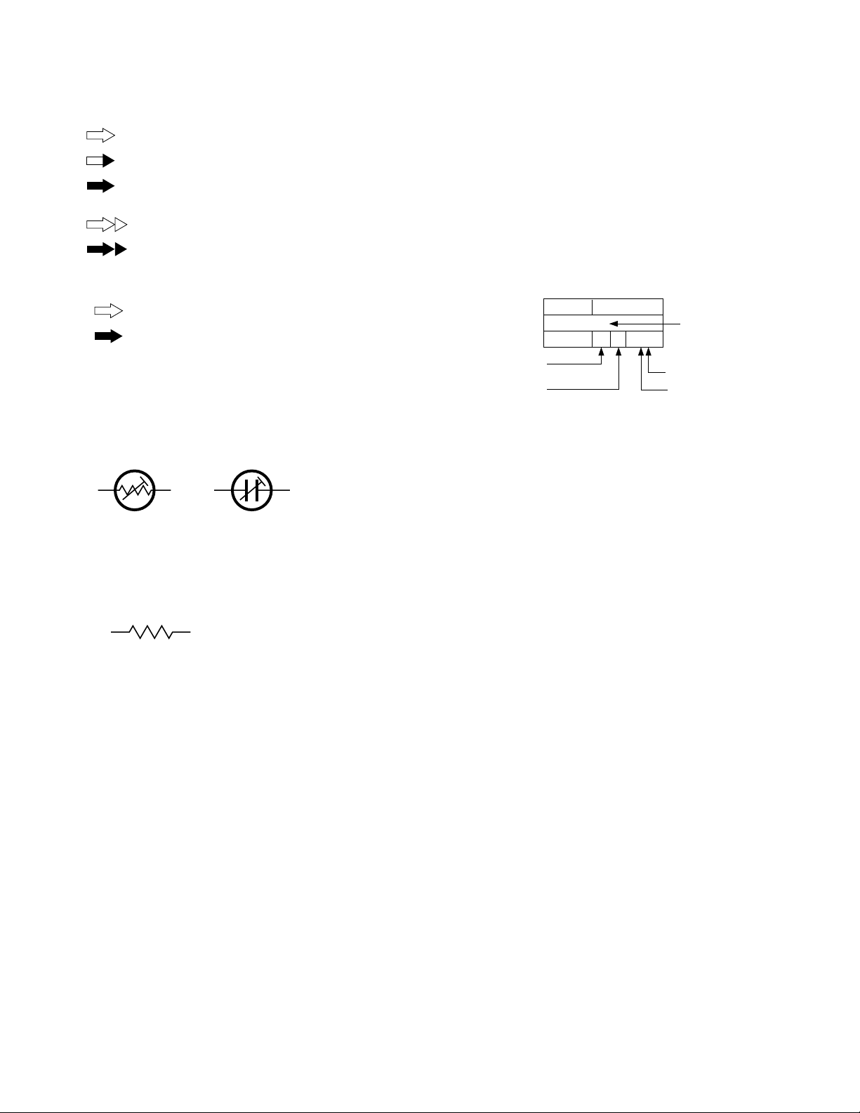
3. Interpreting Connector indications
1
2
Removable connector
3
1
2
Wire soldered directly on board
3
4) Indication on schematic diagram
Voltage Indications for REC and PB mode on the schematic diagram are as shown below.
REC mode
12 3
2.5
(5.0)
PB mode
1.8
PB and REC modes
(Voltage of PB and REC modes
are the same)
Note: If the voltages are not indicated on the schematic
diagram, refer to the voltage charts.
5. Waveform measurement
1) Video circuits
REC : Colour bar signal in SP mode, normal VHS mode
PB : Alignment tape, colour bar SP mode, normal VHS
mode
2) Audio circuits
REC : 1KHz, –8 dBs sine wave signal in SP mode, normal
VHS mode
PB : REC then playback it
3) Movie Camera circuits
Measured using a correctly illuminated gray scale or colour
bar test chatrs in the E-E mode
4) Indication on schematic diagram
Waveform indications on the schematic diagram are as
shown below.
1
Non-removable Board connector
2
3
1
2
4
Board to Board
3
Connected pattern on board
The arrows indicate signal path
4. Voltage measurement
1) Video circuits
REC : Colour bar signal in SP mode, normal VHS mode
PB : Alignment tape, colour bar SP mode, normal VHS
mode
— : Unmeasurable or unnecessary to measure
2) Audio circuits
REC : 1KHz, –8 dBs sine wave signal in SP mode, Nor-
mal VHS mode
PB : REC then playback it
3) Movie Camera circuits
Measured using a correctly illuminated gray scale or colour
bar test charts in the E-E mode
5) Waveform indications
Waveform number
WF25
REC/PB 1.2 Vp-p
50 mV/2 msec/DIV
Oscilloscope Volts and Time/Division, Probe 10 : 1
Mode : REC or PB modes
Waveform name or
measurement point
ALC OUT
Level : 1.2 Vp-p
4-1
Page 2
6. Signal path Symbols
The arrows indicate the signal path as follows.
Playback signal path
Playback and recording signal path
Recording signal path
(including E-E signal path)
Capstan servo path
CIRCUIT BOARD NOTES
1. Foil and Component sides
1) Foil side (B side) :
Parts on the foil side seen from foil face (pattern face)
are indicated.
2) Component side (A side) :
Parts on the component side seen from component face
(parts face) indicated.
Drum servo path
(Example)
R-Y
Playback R-Y signal path
Y
Recording Y signal path
7. Indication of the parts for adjustments
The parts for the adjustments are surrounded with the circle as
shown below.
8. Indication of the parts not mounted on the circuit board
“OPEN” is indicated by the parts not mounted on the circuit
board.
R216
OPEN
2. Parts location guides
Parts location are indicated by guide scale on the circuit board.
REF No. LOCATION
Category: IC
Horizontal “A” zone
Vertical “6” zone
(A : Component side)
(D : Discrete component)
B : Foil side
C : Chip component
IC
IC101 B C 6 A
Note:
For general information in service manual, please refer
to the Service Manual of GENERAL INFORMATION Edition 4 No. 82054D (January 1994).
4-2
Page 3
4.1 BOARD INTERCONNECTIONS
5
)
A
(
(
ENABLE MOD OUT
Page 4-13
)
4
(
VIDEO/AUDIO Page 4-5
(
SYSCON Page 4-7
(
SW.REG Page 4-9
(
TERMINAL Page 4-11
)
)
)
)
3
CAP CTL V
2
LP/EP LP/EP
1
p20175001a rev0
ABCD EFGH
4-3 4-4
Page 4
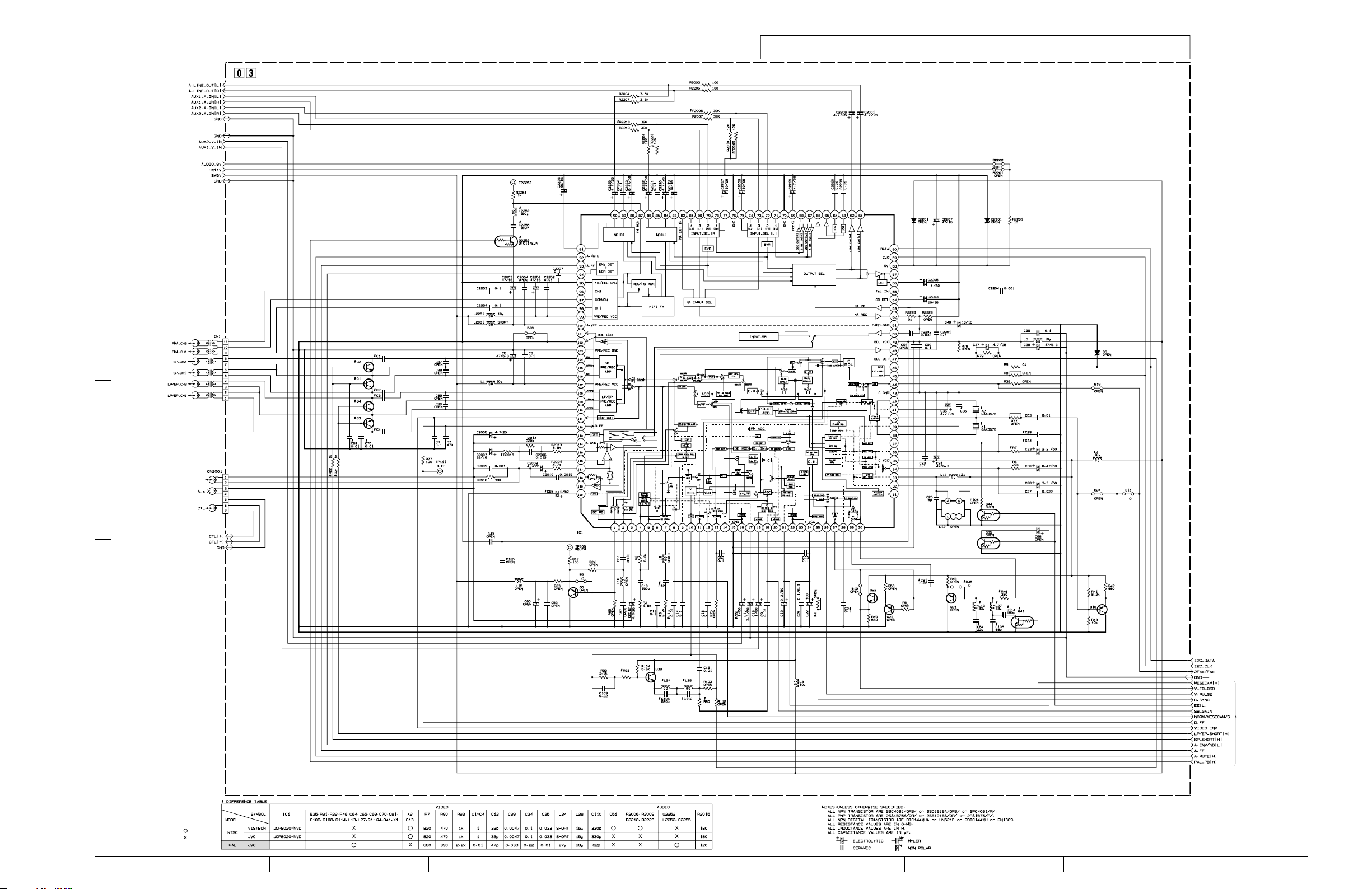
4.2 MAIN(VIDEO/AUDIO)SCHEMATIC DIAGRAM
The Parts Number,value and rated voltage etc. in the Schematic Diagram are for references only.
Note :
When replacing the parts,refer to the Parts List.
TO TERMINAL
MAIN(VIDEO/AUDIO
)
5
TO SW.REG
4
TO U.DRUM
HIFI MODEL HIFI MODEL
3
TO A/C HEAD
CN1
P/R
TO SYSCON
0
0
0
2
TO SYSCON
TO SW.REG
TO SYSCON
1
: Used
: Not used
JCP8020-MSD-2
4-5 4-6
p10294001a rev1.1
HGFEDCBA
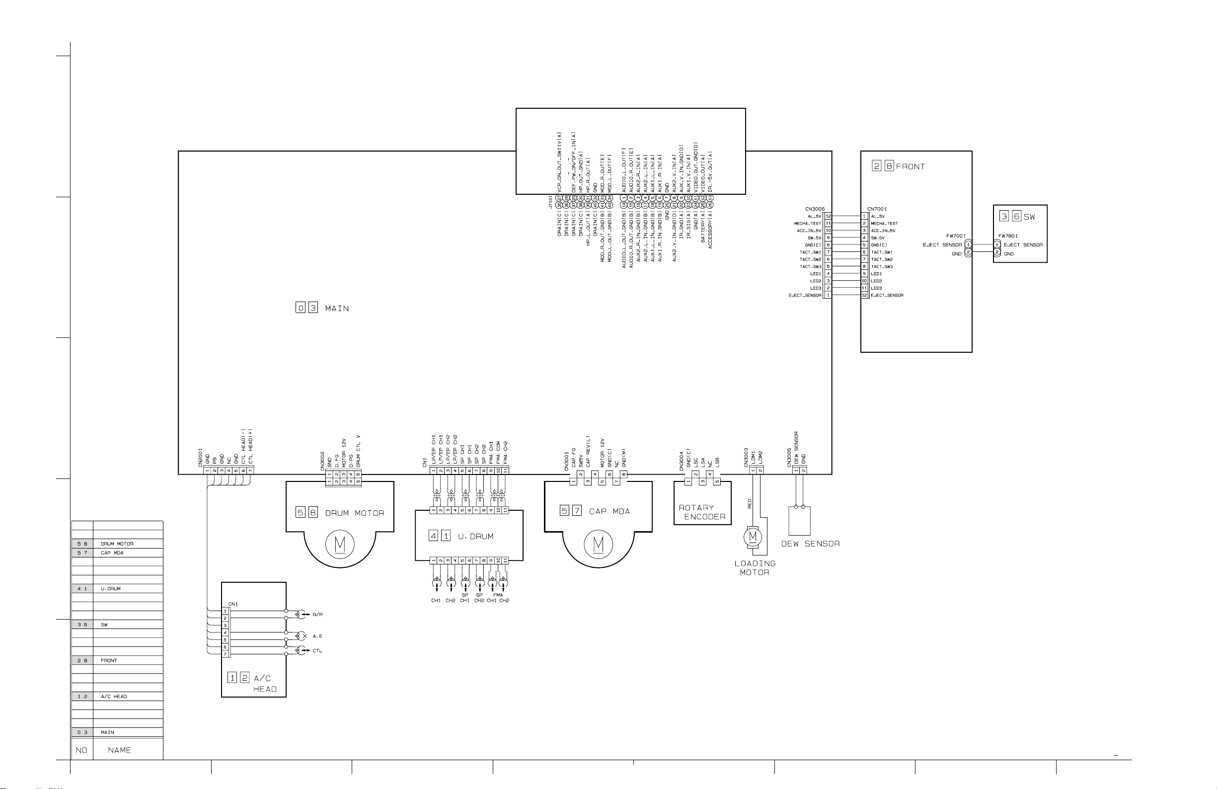
Page 5
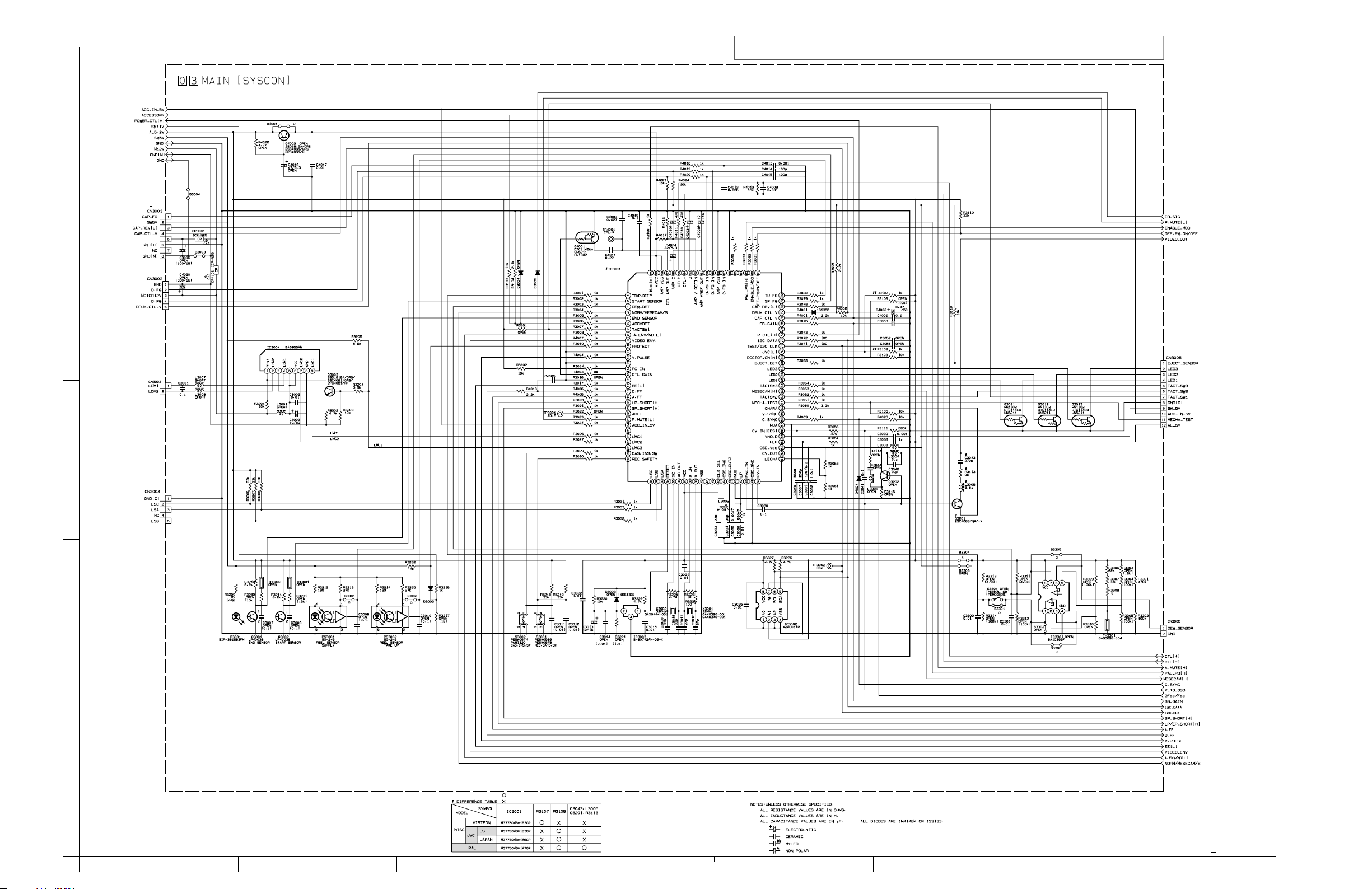
4.3
MAIN(SYSCON)SCHEMATIC DIAGRAM
The Parts Number,value and rated voltage etc. in the Schematic Diagram are for references only.
Note :
When replacing the parts,refer to the Parts List.
TO SW.REG
0
5
TO CAP MDA
MONITOR 12V
TO DRUM MOTOR
SHORT
TO TERMINAL
OPEN
4
TO FRONT
CN7001
TO LOADING MOTOR
3
TO ROTARY ENCORDER
2.2
0
0
2
0
0
0
TO DEW SENSOR
0
TO VIDEO/AUDIO
1
: Used
: Not used
p10295001a rev1.1
ABCD EFGH
4-7 4-8
Page 6

4.4
MAIN(SW.REG)SCHEMATIC DIAGRAM
The Parts Number,value and rated voltage etc. in the Schematic Diagram are for references only.
Note :
When replacing the parts,refer to the Parts List.
MAIN(SW.REG
)
TO SYSCON
5
R5056
47
TO SYSCON
OPEN
TO TERMINAL
TO VIDEO/AUDIO
4
TO VIDEO/AUDIO
TO TERMINAL
,
SYSCON
22/63
TO VIDEO/AUDIO,SYSCON
TERMINAL
,
TO TERMINAL
3
TO SYSCON
,
22/63
TO VIDEO/AUDIO,SYSCON
TERMINAL
2
10k
: Used
: Not used
TO SYSCON
TO TERMINAL
TO SYSCON
1
p30076001a rev0.1
4-9 4-10
HGFEDCBA
Page 7

4.5
MAIN(TERMINAL)SCHEMATIC DIAGRAM
The Parts Number,value and rated voltage etc. in the Schematic Diagram are for references only.
Note :
When replacing the parts,refer to the Parts List.
MAIN(TERMINAL
)
TO VIDEO/AUDIO
5
TO SW.REG
TO VIDEO/AUDIO
TO SYSCON
TO SW.REG
OPEN
4
TO SW.REG
TO SYSCON
TO SW.REG
3
SHORT
SHORT
2
: Used
1
ABCD EFGH
: Not used
p20176001a rev1
4-11 4-12
Page 8

4.6 FRONT SCHEMATIC DIAGRAM
The Parts Number,value and rated voltage etc. in the Schematic Diagram are for references only.
5
Note :
When replacing the parts,refer to the Parts List.
TO SYSCON
CN3006
4
3
TO SW
FW7801
2
: Used
: Not used
1
4-13 4-14
p30075001a rev0
HGFEDCBA
Page 9

4.7 WAVEFORMS 4.8 VOLTAGE CHARTS
<VIDEO/AUDIO>
< SYSCON >
WF1
50 mV/0.5 msec/DIV
CN3001-1
CAP_FG
PB 2.1 Vp-p
< VIDEO >
WF1
PB 2.2 Vp-p
50 mV/20 µsec/DIV
< AUDIO >
WF1
PB 0.9 Vp-p
20 mV/0.5 msec/DIV
IC1-27
IC1-62
WF2
CN3002-4
PB 4.5 Vp-p
0.2V/10 msec/DIV
WF2
PB 0.64 Vp-p
20 mV/20 µsec/DIV
WF2
PB 0.72 Vp-p
20 mV/0.5 msec/DIV
D.PG
IC1-30
IC1-48
WF3
CN3002-2
PB 4.6 Vp-p
0.1 V/0.5 msec/DIV
WF3
PB 0.4 Vp-p
20 mV/5 msec/DIV
WF3
PB 0.8 Vp-p
50 mV/5 msec/DIV
D.FG
TP106
PB FM
TP2253
A.FM
WF4
PB 3.5 Vp-p
50 mV/10 msec/DIV
WF4
PB 3.2 Vp-p
0.1 V/10 msec/DIV
TP4001
CTL.P
TP111
D.FF
WF5
IC3001-58
PB 4.2 Vp-p
0.1 V/20 µsec/DIV
WF5
PB 0.52 Vp-p
20 mV/20 µsec/DIV
C.SYNC
IC1-13
WF6
IC3001-50
PB 2.2 Vp-p
50 mV/20 µsec/DIV
WF6
PB 0.48 Vp-p
20 mV/20 µsec/DIV
4-15 4-16
CV_IN
IC1-11
MODE
PIN NO.
IC1
PLAY
12.1
22.9
32.6
41.5
51.5
62.2
70
80
93.1
10 2.4
11 0
12 0
13 0
14 2.4
15 0
16 0
17 1.4
18 2.8
19 0
20 2.8
21 1.9
22 0
23 2.9
24 4.9
25 0.3
26 0
27 0
28 2.4
29 1.9
30 2.2
31 0
32 2.7
33 4.9
34 2.4
35 4.9
36 2.7
37 2.3
38 39 1.2
40 41 2.6
42 43 0
44 2.2
45 4.7
46 4.7
47 2.9
48 2.6
49 4.9
50 2.5
51 2.9
52 2.3
53 2.3
54 2.5
55 2.2
56 0.4
57 2.3
58 8.8
59 4.7
60 4.7
61 4.4
62 4.5
63 2.3
64 2.3
65 0.8
66 0.6
67 8.7
68 8.6
69 2.3
70 0
71 3.5
72 0.2
73 0.2
74 2.3
75 2.6
76 0
77 2.6
78 3.5
79 0.2
80 0.2
81 2.2
82 0.8
83 0
84 2.3
85 2.3
86 2.3
87 1.7
88 2.3
89 2.3
90 2.3
91 0.1
92 0
93 2.4
94 1.9
95 0
96 2.3
97 2.3
98 2.3
99 4.9
100 4.9
MODE
PIN NO.
IC3001
PLAY
101 0
102 0
103 0
104 2.3
105 2.2
106 2.2
107 4.9
108 0
109 0
110 0
111 3. 0
112 2.5
113 0.5
114 0
115 2.6
116 2.5
117 2.5
118 0
119 2.5
120 0
1 3.9
2 4.7
30
40
5 4.7
6 2.5
7 4.8
8 1.8
9 3.0
10 4.9
11 0
12 0
13 0
14 4.8
15 4.8
16 0
17 4.8
18 2.4
19 2.4
20 0
21 0
22 0
23 4.8
24 4.3
25 0
26 0
27 0
28 0
29 0
30 4.8
31 4.8
32 0
33 4.8
34 35 36 37 4.9
38 39 40 0
41 42 43 4.9
44 2.3
45 2.3
46 0
47 1.3
48 2.2
49 0
50 1.7
51 2.5
52 1.7
53 4.9
54 2.0
55 0.3
56 1.8
57 0
58 0.3
59 0
60 0
61 4.9
62 4.8
63 0
64 4.8
65 4.8
66 0
67 4.8
68 4.9
69 0
70 4.9
71 4.7
72 4.7
73 4.8
74 0
75 0
76 2.5
77 1.1
78 4.8
79 80 -
MODE
PIN NO.
IC3002
IC3003
IC3004
IC5001
IC5002
IC7101
CN1
CN2001
CN3001
CN3002
PLAY
81 4.8
82 0
83 0
84 0
85 0
86 0
87 2.4
88 0
89 0
90 0.6
91 2.4
92 2.4
93 1.0
94 2.4
95 2.4
96 2.4
97 2.4
98 4.9
99 4.8
100 0
10
230
40
5 4.7
6 4.8
70
8 4.8
12 4.8
30
1 11.2
2 0.8
30
4 0.7
5 11.3
6 11.2
70
80
90
1 1.3
20
3 3.6
4 11.6
5 8.8
1 0.3
2 4.8
3 4.8
40
5 4.7
6 4.6
7 0.8
8 11.6
1 5.2
2 5.1
3 5.1
40
5 5.1
6 5.1
7 5.1
8 10.3
10
20
30
40
5 2.2
6 2.2
7 2.2
8 2.2
9 2.3
10 2.3
11 2.3
10
20
30
40
50
6 2.4
7 2.4
1 2.5
2 4.9
3 4.8
4 2.4
5 11.3
60
70
80
10
2 2.3
3 11.3
4 0.5
MODE
PIN NO.
CN3003
CN3004
CN3005
CN3006
PLAY
5 1.5
1 0.6
2 0.6
10
2 4.8
3 4.8
40
50
10
20
1 4.9
20
3 4.3
40
5 4.9
6 4.9
7 4.8
80
9 4.9
10 4.4
11 4.9
12 4.8
<FRONT>
MODE
PIN NO.
CN7001
FW7001
PLAY
1 4.8
2 4.9
3 4.4
4 4.9
50
6 4.8
7 4.9
8 4.9
90
10 4.3
11 0
12 4.9
1 4.9
20
<SW>
MODE
PIN NO.
FW7801
PLAY
1 4.9
20
Page 10

4.9 MAIN,FRONT AND SW CIRCUIT BOARDS
,
LPB10120-001C
36 SW03 MAIN,28 FRONT
CAUTION :
TF
FOR CONTINUED PROTECTION AGAINST FIRE HAZARD,REPLACE ONLY WITH SAME TYPE AND RATED FUSE(S).
FOR CONTINUED PROTECTION AGAINST FIRE HAZARD,REPLACE ONLY WITH SAME TYPE CP(S)MANUFACTURED BY ROHM.
ATTENTION :
REPLACER PAR DES FUSIBLE DE MEME TYPE.
MAIN/FORNT PWB ASS'YLPA10120 -
1
2
FW7801
SW PWB ASS'Y
LPA10120 C3
S7801
36
S7006
CN7001
PAU S E
S7004
POWER
12
11
2
1
2
FW7001
1
B7001
SPEAKER
POWER
D7006
R7016
R7017
R7007
TP7001
MECHA TEST
GND
TP7002
D7004
R7006
PAU S E
SPEAKER
B7002
R7014
B7003
Q7001Q7002
R4021
D5051
CN3002
1
2
C4020
B3004
ICP-N25
20N1500
CP4101
L3001
B3003
WR5 WR3
R5051
L3008
L3007
C7101
Q7102
5
4
R7115
R3201
1
IC3004
C3002
9
R4024
Q3002
START
SENSOR
R7116
W2
C3001
Q3003
C3003
2
Q7101
C7104
R3202
CN3003
1
R7117
R7118
C7103
R3203
L7101
ZZ1
R7167
R7166
R7165
R7164
R7114
C7102
R7113
13
R7101
C7163
12
R7104
C7161
B7101
R7102
C7164
5
4
R7162
23 22 21242526
R7169
R7105
R7168
C7160
9
WR4
R7163
R7112
20 19 18
R7107
R7103
C7166
C7165
8
1
C7112
R7160
C7162
IC7103
567811
W3
W11
W9
W8
43
R7110
R7161
R7171
W10
1617 15 14
34
2110
17
CN2001
R7170
Q7109
R112
R7109
W30
C110
Q23
R7106
L28
C15
C23
CP3001
ICP-N25
20N1500
R103
L24
Q7108
R7108
ZZ4
R49
R90
C22
R7183
L15
L2
C28
R6
X2
D3001
C12
C14
R37
B7112
Q7112
CN3005
TP2253
R7182
21
TP106
PB FM
W13
W14
C57
Q5
L16
R23
R2
C38
C37
R1
R24
R12
C61
C10
IC1
31
WR1
WR2
C39
R79
R2228
R78
C125
L5
C2203
C11
C59
C60
30
C27
C25
L11
L12
W12
C32
X1
R36
B19
C2201
R8
B11
R9
C97
2829
CN3001
1
R92
C36
L27
Q21
Q44
R7181
C99
W4
R7
W24
35
27
R105
L4
R3209
4
8
C33
C17
C35
ZZ2
C30
Q7111
C13
C51
C34
R41
R42
R3
C29
C53
R43
C2204
C31
Q10
B24
J7101
38 37 36
39404142
30
3233
31
R7111
Q7106
C7106
Q7107
C3006
5
R93
Q38
R104
C109
WR2
C106
R75
C62
C16
C18
W6
R5
R50
W7
C19
C21
W5
C24
L3
B12
R48
Q22
C9
R4
R46
C81
B35
C64
L13
C98
Q35
B5
60
C40
C2202
C2009
1
C2209
C2210
R2229
C2205
WR3
R2016
R65
C65
TP4001
CTL.PA.FM
C2007
R2015
C2008
B7111
C2006
R2014
120
C2001
C2207
TP111
D.FF
61
ZZ5
C2005
C2010
R2003
R2004
R2013
R2024
D6
C2002
C2215
W15
R2207
D2101
W25
R77
Q3
C2012
C4
2
C90
90
C2208
1
C7
C89
WR1
B28
91
C2217
R2006
R2201
R2206
C8
Q4
C70
C43
D2201
CN1
C3
C2224
R2223
C7146
C5
R2009
11
10
Q1
C2
C87C88
C2226
C69
C2251
R2224
R2007
R2010
R3302
R3301
Q2
W22
W28
C6
C2252
C2219
R2218
TH3301
R3310
R3305
C1
C2254
C7126
R3303
R22
R2219
C7125
C7145
W19
L2251
C2253
C2227
C2225
C2220
R3308
B3306
4
5
R3304
C2003
C2223
R3309
R21
B3305
L2252
C2222
1
R3311
R3313
8
L2001
IC3301
R3306
W20
C2004
L1
C2255
R2251
C2221
R3307
R3312
B2201
W21
C3301
C3302
Q2252
R3314
R7132
R7131
B3302
B3301
S3301
ZZ3
B7122
R7120
C7121
R7123
1
R7124
IC7101
R7126
8
R7130
R7129
B7121
C7124
R7133
R7140
B7142
14
W16
R7144
8
R7153
C7144
B7141
R3232
R3217
R7143
IC7102
R7151
R7152
ZZ6
R3216
C7143
D3002
C7120
C7141
TP5002
W18
W17
R7121
4
R7122
R7125
C7122
5
C7142
R7142
R7141
R7146
5
R7148
R7149
R7150
Q3001
END SENSOR
GND
C7123
C7140
R7145
R7127
R7128
R7147
C3037
C3038
R3113
L5006
W26
R4012
R3056
C3039
R3054
L3003
3
R4011
C3040
R5010
L5007
D5006
R4010
R3114
L3005
C4009
81
80
C3044
D5006
R4017
C4003
R3085
R4026
R4009
D5007
R3072
R3060
D4004
L3006
D5010
C5013
C4010
R3071
C3052
C3051
D3004
R3101
C3008
R3211
PLAY/PAUSE
D7003
R7013
PLAY/PAUSE
REW
R7001
FF
STOP/EJECT
FF
D7002
STOP/EJECT
D7005
R7003
D7001
R7002
REW
LPB10120 -001C
R7011
R7012
R7015
R7005
MAIN/FRONT PWB
S7003
S7001
S7002
S7005
V1
R3231
TH3001
WR5
S3002
CASS
B5003
CN3004
R3206
ZZ7
R3218
C3011
L5001
W1
R5032
R4013
D5001
R5030
R4003
5
R3208
R5031
B5004
R3027
R3204
C5001
R3029
R3205
R3207
Q5007
R3214
C5002
C5019
C5018
R5052
C5052
WR4
20N1500
D5008
R5028
C3010
R3215
C5051
ICP-N25
CP5002
R3102
D5009
R3103
D3005
C4005
R3016
R3024R3026
PS3002
45
31
R3031
21
B3002
R3033
IC5001
R5055
R5054
3
1
4
5
B5002
R5056
R5042
VA5001
Q5001
C5003
CP5001
ICP-N25
20N1500
L5002
Q5002
B
L5005
E
R5002
R5029
C4016
R3104
R3014
R4004
R4005
R4006
TP3001
R3032
R5053
D5041 R5043
ADLE
C5053
Q5008
C5007
C3013
D3003
C3014
C5054
C5004
R3022
R3030
Q5041
B
E
D5004
R5004
R3020
C3022
R5041
R5044
R5006
R5007
Q5003
R5003
R3021
R3007
IC3003
3
R3221
C5005
R5008
8
R5022
R4022
R3220
R3222
L5003
1
C5008
R3006
R3010
R3017
1
C3036
R5005
C5014
W29
W23
ZZ8
C5012
Q4002
R3003
C3015
C3020
C3016
C3035
R3047
R5013
R5018
R5025
R3004
R3023
R3225
C3034
IC5002
4
R5011
5
X3002
C3018
D5005
R5020
R3001
R4007
31
C3017
C5006
R5012
R5021
R3005
IC3001
30
X3001
L3002
C3033
R5024
C3021
D5003
B4001
R3008
R3224
C5011
R5014
C4017
R3002
R3223
R5023
C5020
E
50
R3111
C3030
C3041
C5009
R5019
Q4001
C4019
R5015
R3100
R3051
L3004
B
C4007
C4011
1
C3042
B5001
B5005
Q5004
R5016
R3053
C3032
C3043
R5009
R5017
51
C3031
Q3202
R3115
VR5001
SW5V
1
100
W27
2
Q5005
C4004
R3080
R3063
R3062
R3061
R3105
L5004
L5008
R4020
R3079
R3064
Q3201
R5027
R4016
C4015
R3109
C5015
C4008
C4013
C4014
D4001
R3078
R3068
R4019
R4001
C3009
Q3013
Q3011
R5026
C5016
C4012
B3001
R3213
Q3012
R3107
C108
Q5006
R4018
R3083
R3075
2
R3108
R3106
Q41
C114
C5010
C5017
R4002
C4001
R3073
C3053
D5002
C5017
R3082
3
1
TP3002
R3081
R3112
5
4
C4002
R4025
IC3002
R3110
4
5
R3226
B2202
PS3001
C5021
R3212
1
8
R3227
C3025
12
R3230
C3007
B3303
R3210
TH3002
B3304
ZZ9
2
1
S3001
REC SAFE
C3012
R3219
CN3006
11
4-17 4-18
Page 11

MAINCOMPONENT PARTS LOCATION GUIDE
REF.NO. LOCATION REF.NO. LOCATION REF.NO. LOCATION REF.NO. LOCATION REF.NO. LOCATION REF.NO. LOCATION REF.NO. LOCATION REF.NO. LOCATION
CAPACITOR
C1 B C 12N
C2 B C 12M
C3 B C 12M
C4 B C 11N
C5 A D 12M
C6 B C 12M
C7 B C 11N
C8 B C 12N
C9 B C 7L
C10 B C 10M
C11 B C 9M
C12 B C 8M
C13 B C 8M
C14 B C 9M
C15 B C 6M
C16 B C 7M
C17 A D 8L
C18 A D 7L
C19 A D 7L
C21 B C 7L
C22 A D 6K
C23 B C 6L
C24 B C 7K
C25 B C 9L
C27 B C 9L
C28 A D 8L
C29 B C 8K
C30 A D 8L
C31 A D 8K
C32 B C 8K
C33 A D 8K
C34 B C 8K
C35 B C 8K
C36 A D 7K
C37 A D 9J
C38 A D 9K
C39 B C 9K
C40 A D 10K
C43 B C 12M
C51 A D 8L
C53 B C 8J
C57 B C 9N
C59 B C 9M
C60 B C 9M
C61 B C 9N
C62 B C 7M
C64 B C 7K
C65 A D 10N
C69 B C 12N
C70 B C 12N
C81 B C 7K
C87 B C 12M
C88 B C 12M
C89 B C 12N
C90 B C 11M
C97 B C 9J
C98 B C 7J
C99 B C 7L
C106 B C 6M
C108 B C 12D
C109 B C 7M
C110 B C 6M
C114 B C 12D
C125 B C 10J
C2001 A D 11J
C2002 A D 11K
C2003 A D 13M
C2004 B C 14M
C2005 A D 11N
C2006 B C 11N
C2007 A D 11N
C2008 A D 10N
C2009 B C 10N
C2010 B C 11M
C2012 A D 11N
C2201 B C 9J
C2202 B C 9J
C2203 A D 9I
C2204 B C 8J
C2205 A D 10I
C2207 A D 11J
C2208 A D 11J
C2209 B C 10J
C2210 B C 10J
C2215 A D 11K
C2217 A D 12K
C2219 A D 13K
C2220 A D 13K
C2221 B C 13L
C2222 A D 13K
C2223 A D 13L
C2224 B C 12L
C2225 A D 13L
C2226 A D 12L
C2227 B C 13L
C2251 A D 12M
C2252 A D 13M
C2253 B C 13M
C2254 B C 13M
C2255 B C 14M
C3001 B C 2O
C3002 B C 2K
C3003 A D 2K
C3006 A D 7M
C3007 B C 15H
C3008 B C 2H
C3009 B C 12F
C3010 B C 6F
C3011 B C 3C
C3012 B C 15B
C3013 A D 7F
C3014 B C 7F
C3015 B C 8F
C3016 B C 8E
C3017 B C 9E
C3018 B C 8F
C3020 B C 8F
C3021 B C 8E
C3022 B C 7E
C3025 B C 13E
C3030 B C 9D
C3031 A D 10E
C3032 B C 10E
C3033 B C 8E
C3034 B C 8E
C3035 B C 8E
C3036 B C 8E
C3037 B C 10E
C3038 B C 10E
C3039 B C 10E
C3040 B C 10E
C3041 B C 9D
C3042 B C 10D
C3043 B C 10D
C3044 B C 11E
C3051 B C 11F
C3052 B C 11F
C3053 B C 13F
C3301 B C 14O
C3302 B C 14N
C4001 B C 13G
C4002 A D 13G
C4003 A D 11H
C4004 A D 11H
C4005 A D 6G
C4007 B C 10H
C4008 A D 12H
C4009 B C 10H
C4010 A D 11H
C4011 B C 10H
C4012 B C 12H
C4013 B C 12H
C4014 B C 12H
C4015 B C 11H
C4016 A D 7H
C4017 B C 9H
C4019 B C 9H
C4020 A D 2L
C5001 A D 5B
C5002 A D 5B
C5003 A D 6B
C5004 B C 7B
C5005 B C 7B
C5006 A D 8B
C5007 A D 7B
C5008 B C 7A
C5009 A D 9B
C5010 A D 12B
C5011 A D 9A
C5012 B C 8A
C5013 A D 11A
C5014 B C 7A
C5015 A D 12A
C5016 A D 12A
C5017 A D 12B
C5018 B C
13BDAC5021
4A
4ACBC5019
9BDAC5020
CONNECTOR
DIODE
IC
JACK
COIL
15MDAC7120
15MDAC7121
16LDAC7122
16KDAC7123
15KDAC7124
13KDAC7125
12KDAC7126
16KDAC7140
15KDAC7141
16KDAC7142
13KDAC7145
12KDAC7146
12ODACN1
15ADACN3006
12GCBD4001
11ECBD4004
12BDAD5002
10ADAD5006
11ADAD5007
11BDAD5010
10LCBIC1
10FCBIC3001
13EDAIC3002
13OCBIC3301
15LDAIC7101
15KDAIC7102
14MDAL1
5CDAC5051
5CCBC5052
6CDAC5053
7CCBC5054
2MDAC7101
2MCBC7102
2LDAC7103
2LCBC7104
7NCBC7106
5PCBC7112
16JDAC7143
15JDAC7144
4MDAC7160
4MDAC7161
5MDAC7162
3NDAC7163
4NDAC7164
4NDAC7165
4NDAC7166
6ODACN2001
7NDACN3001
1MDACN3002
3ODACN3003
4FDACN3004
9ODACN3005
11IDAD6
11JDAD2101
12JDAD2201
15IDAD3002
7FDAD3003
5HDAD3004
6HDAD3005
4BDAD5001
9BDAD5003
7BDAD5004
8BDAD5005
5ADAD5008
5BDAD5009
6CDAD5041
2PDAD5051
7FCBIC3003
2LDAIC3004
6CCBIC5001
7BDAIC5002
4MDAIC7103
5PDAJ7101
8MDAL2
6JDAL3
8JDAL4
9LDAL11
8KDAL12
7JDAL13
8NDAL15
9NDAL16
8IDAD3001
9IDAL5
TRANSISTOR
RESISTOR
7MDAL24
7KDAL27
6MDAL28
14NDAL2001
13MDAL2251
14LDAL2252
2LDAL3001
8EDAL3002
10EDAL3003
10EDAL3004
10DDAL3005
11DDAL3006
2NDAL3007
2ODAL3008
4BDAL5001
6BDAL5002
7BDAL5003
11BDAL5004
5BDAL5005
10ADAL5006
10BDAL5007
11BDAL5008
3LDAL7101
12NCBQ1
12NCBQ2
12NCBQ3
12NCBQ4
10NCBQ5
8JCBQ10
7KCBQ21
7KCBQ22
6KCBQ23
7JCBQ35
6MCBQ38
12DCBQ41
7JCBQ44
14MCBQ2252
16IDAQ3001
1IDAQ3002
2LCBQ3003
12ECBQ3011
12ECBQ3012
12ECBQ3013
11DCBQ3201
10DCBQ3202
9HCBQ4001
8HCBQ4002
6BCBQ5001
6ADAQ5002
7ACBQ5003
9ADAQ5004
10ACBQ5005
12BCBQ5006
5ACBQ5007
6BCBQ5008
7BDAQ5041
2MCBQ7101
2MCBQ7102
7NCBQ7106
6NCBQ7107
5NCBQ7108
5NCBQ7109
8PCBQ7111
9PCBQ7112
10MCBR1
9MCBR2
8MCBR3
7LCBR4
6KCBR5
8LCBR6
8KCBR7
9JCBR8
9JCBR9
9NCBR12
13NCBR21
12NCBR22
9NCBR23
10NCBR24
9JCBR36
8KCBR37
8JCBR41
8JCBR42
8JCBR43
7KCBR46
7KCBR48
6KCBR49
6KCBR50
10NCBR65
7MCBR75
11NCBR77
9JCBR78
9JCBR79
6LCBR90
7MCBR92
7MCBR93
6MCBR103
7MCBR104
8KCBR105
6MCBR112
11JCBR2003
11JCBR2004
12KCBR2006
12KCBR2007
12KCBR2009
12KCBR2010
11NCBR2013
11NCBR2014
11NCBR2015
10NCBR2016
11NCBR2024
12JDAR2201
11JCBR2206
11JCBR2207
12KCBR2218
13KCBR2219
12KCBR2223
12KCBR2224
10JCBR2228
10JCBR2229
14LCBR2251
8HCBR3001
9HCBR3002
8HCBR3003
8HCBR3004
9HCBR3005
8HCBR3006
8GCBR3007
9GCBR3008
8GCBR3010
7HCBR3014
6GCBR3016
8GCBR3017
7GCBR3020
7GCBR3021
7GCBR3022
8GCBR3023
5GCBR3024
6GCBR3026
5GCBR3027
5GCBR3029
7FCBR3030
6FCBR3031
6FCBR3032
6FCBR3033
8DCBR3047
9ECBR3051
10ECBR3053
10ECBR3054
10ECBR3056
11ECBR3060
11ECBR3061
11ECBR3062
11ECBR3063
11ECBR3064
12ECBR3068
11FCBR3071
11FCBR3072
12GCBR3073
12GCBR3075
12GCBR3078
11GCBR3079
11GCBR3080
13HCBR3081
12HCBR3082
12HCBR3083
11GCBR3085
10HCBR3100
5HCBR3101
5HCBR3102
6HCBR3103
7HCBR3104
11ECBR3105
12ECBR3106
12ECBR3107
12ECBR3108
11FDAR3109
13GDAR3110
9DCBR3111
13HCBR3112
10DCBR3113
10ECBR3114
10DCBR3115
2LCBR3201
2KCBR3202
2KCBR3203
5GCBR3204
5FCBR3205
3ECBR3206
5FCBR3207
4FCBR3208
8IDAR3209
16HCBR3210
2HCBR3211
13FCBR3212
12FCBR3213
5FCBR3214
6FCBR3215
15ICBR3216
15ICBR3217
3CCBR3218
14BCBR3219
7ECBR3220
7FCBR3221
8FCBR3222
9ECBR3223
9FCBR3224
8FCBR3225
13ECBR3226
13ECBR3227
16HCBR3230
2HCBR3231
15ICBR3232
13OCBR3301
13OCBR3302
13OCBR3303
13NCBR3304
13OCBR3305
14OCBR3306
14OCBR3307
14OCBR3308
13OCBR3309
13OCBR3310
14NCBR3311
14OCBR3312
14NCBR3313
14NCBR3314
12GCBR4001
13GCBR4002
4HCBR4003
7GCBR4004
7GCBR4005
7GCBR4006
8GCBR4007
11ECBR4009
10HCBR4010
10HCBR4011
10HCBR4012
5GCBR4013
11HCBR4016
11HCBR4017
12HCBR4018
12HCBR4019
11HCBR4020
1LCBR4021
7HCBR4022
2JCBR4024
13GCBR4025
11ECBR4026
6ACBR5002
7ACBR5003
7ACBR5004
8ACBR5005
7BCBR5006
7ACBR5007
7BCBR5008
10BCBR5009
10BCBR5010
8ACBR5011
8ACBR5012
8BCBR5013
9ACBR5014
9ACBR5015
9ACBR5016
10ACBR5017
8ACBR5018
9BCBR5019
8ACBR5020
SWITCH
8ACBR5021
TESTPOINT
7ACBR5022
9BCBR5023
8ACBR5024
8ACBR5025
12ADAR5026
12BCBR5027
5ACBR5028
5ACBR5029
4ACBR5030
5BDAR5031
4ADAR5032
7BCBR5041
6CCBR5042
7CDAR5043
7BCBR5044
2PDAR5051
5DCBR5052
6CCBR5053
6DCBR5054
6DCBR5055
6BDAR5056
3OCBR7101
4OCBR7102
4OCBR7103
4OCBR7104
4OCBR7105
6NCBR7106
4NCBR7107
5NCBR7108
6NCBR7109
5OCBR7110
7NCBR7111
5PCBR7112
3MCBR7113
3MCBR7114
2MDAR7115
2MCBR7116
2MCBR7117
2MCBR7118
15MCBR7120
16MCBR7121
16MCBR7122
15MCBR7123
15LCBR7124
16LCBR7125
16LCBR7126
16LCBR7127
16LCBR7128
16LCBR7129
15LCBR7130
15LCBR7131
15LCBR7132
15KCBR7133
15KCBR7140
16KCBR7141
16KCBR7142
15KCBR7143
15JCBR7144
16JCBR7145
16JCBR7146
16JCBR7147
16JCBR7148
16JCBR7149
16JCBR7150
15JCBR7151
15JCBR7152
15JCBR7153
5OCBR7160
5NCBR7161
4MCBR7162
4MCBR7163
3MCBR7164
3MCBR7165
3MCBR7166
3NCBR7167
4NCBR7168
4NCBR7169
5OCBR7170
5NCBR7171
8ODAR7181
9PCBR7182
8PDAR7183
5BDAVA5001
10BDAVR5001
14BDAS3001
3CDAS3002
14NDAS3301
OTHER
10ODATP106
11ODATP111
10ODATP2253
13EDATP3002
10ODATP4001
16PDATP5002
13FDAPS3001
10KDAWR1
10PDAWR3
CPU PIN FUNCTION4.10
<SYSCON IC3001>
PIN NO. LABEL IN/OUT FUNCTION
1 TEMP_DET IN TEMPERATURE DETECTION SIGNAL
2 START SENSOR IN START SENSOR
7GDATP3001
6MDACP3001
2JDACP4101
6BDACP5001
5BDACP5002
6FDAPS3002
9KDAWR2
4ODAWR4
2BDAWR5
9KDAX1
8JDAX2
8FDAX3001
8FDAX3002
3 DEW_DET IN CONDENSATION SENSOR SIGNAL
4 NORM/MESECAM/S IN NORMAL MODE:L
5 END SENSOR IN END SENSOR
6 ACCVDET IN ACCESSORY VOLTAGE DETECT
7 TACTSW1 IN “REW,FF,PLAY,SPEAKER SWITCH INPUT”
8 A.ENV/ND(L) IN AUDIO PB FM ENV. INPUT/NON HiFi MODE:L
9 VIDEO ENV. IN
AUTO TRACKING DETECT/INPUT THE AVERAGE OF PLAYBACK
VIDEO SIGNAL
10 PROTECT IN DETECTION SIGNAL FOR SW POWER SUPPLY
11 - - NC
12 V.PULSE OUT V.PULSE ADDITION TIMING CONTROL
13 - - NC
14 RC IN IN REMOTE CONTROL DATA INPUT
15 CTL GAIN OUT CONTROL AMP OUT FREQUENCY RESPONSE SWITCHING
16 - - NC
17 EE(L) - NC
18 D.FF OUT “VIDEO PB FM(CH1,CH2) SWITCHING PULSE”
19 A.FF OUT AUDIO FF OUTPUT
20 LP_SHORT(H) - NC
21 SP_SHORT(H) - NC
22 ADLE - NC
23 P.MUTE(L) OUT PICTURE MUTE CONTROL (MUTE:H)
24 ACC_IN_5V - 5V
25 - - NC
26 LMC1 OUT LOADING MOTOR DRIVE(1)
27 LMC2 OUT LOADING MOTOR DRIVE(2)
28 LMC3 OUT LOADING MOTOR DRIVE(3)
29 CAS.INS.SW IN CASSETTE TAPE LOAD SWITCH (CASS IN:L)
30 REC SAFETY IN REC SAFETY SWITCH DETECT (SW ON:L)
31 LSC IN MECHANISM MODE DETECT(C)
32 LSB IN MECHANISM MODE DETECT(B)
33 LSA IN MECHANISM MODE DETECT(A)
34 RESET(L) - RESET (RESET:L)
35 XC IN - TIMER CLOCK (32.768kHz)
36 XC OUT - TIMER CLOCK (32.768kHz)
37 VCC - SYSTEM POWER
38 X IN - SYSTEM CLOCK (12MHz)
39 X OUT - SYSTEM CLOCK (12MHz)
40 VSS - GND
41 - - NC
42 - - NC
43 CLK SEL - CONNECT THE VCC (Hi)
44 OSC_IN2 IN CLOCK INPUT FOR OSD CHARACTER
45 OSC_OUT2 OUT CLOCK OUTPUT FOR OSD CHARACTER
46 NUB - CONNECT THE VSS
47 LP IN FILTER INPUT FOR INTERNAL SYNCHRONIZING SIGNAL
48 Fsc_IN IN FSC SIGNAL INPUT FOR OSD
49 OSC_GND - GND FOR OSD
50 CV_IN IN COMPOSITE VIDEO SIGNAL INPUT
PIN NO. LABEL IN/OUT FUNCTIONPIN NO. LABEL IN/OUT FUNCTION
51 LECHA IN WHITH PEAK LEVEL OF COMPOSITE VIDEO SIGNAL INPUT
52 CV_OUT OUT COMPOSITE VIDEO SIGNAL OUTPUT
53 OSD_Vcc - SYSTEM POWER FOR OSD
54 HLF IN LPF CONNECT TERMINAL FOR CLOSED CAPTION DECODER
55 VHOLD IN
CAPACITOR CONNECT TERMINAL FOR CLOSED CAPTION
DECODER REFERENCE VOLT
56 CV_IN(EDS) IN COMPOSITE VIDEO SIGNAL INPUT (FOR EDS)
57 NUA - CONNECT THE VSS
58 C.SYNC IN COMPOSITE SYNC
59 V_SYNC - NC
60 CHARA OUT CHARACTER DATA OUTPUT
61 MECHA_TEST OUT MECHANISM TEST MODE OUTPUT
62 TACTSW2 IN STOP/EJECT SWITCH INPUT
63 MESECAM(H) OUT MESE CAM: H
64 TACTSW3 IN POWER SWITCH INPUT
65 LED1 OUT SPEAKER LED (SPEAKER ON:L)
66 LED2 OUT POWER SW INPUT (STADBY:L)
67 LED3 OUT POWER SW INPUT (POWER ON:L)
68 EJECT_DET IN EJECT SENSOR INPUT
69 DOCTOR_ON(H) - NC
70 JVC(L) IN JVC MODEL:L
71 TEST/I2C_CLK OUT MECHANISM TEST MODE/I2C DATA TRANSFER CLOCK
72 I2C_DATA IN/OUT I2C DATA INPUT/OUTPUT
73 P CTL(H) OUT POWER ON/OFF CONTROL (POWER ON:H)
74 - NC
75 SB_GAIN OUT
VOLTAGE CONTROL SIGNAL FOR VIDEO FREQUENCY
RESPONSE
76 CAP CTL V OUT CAPSTAN MOTOR CONTROL
77 DRUM CTL V OUT DRUM MOTOR CONTROL
78 CAP REV(L) OUT CAPSTAN MOTOR REVERSE CONTROL (FWD:H/REV:L)
79 SP FG IN
80 TU FG IN
DETECTION SIGNAL FOR SUPPLY REEL ROTATION/TAPE REMAIN
DETECTION SIGNAL FOR TAKE-UP REEL ROTATION/TAPE
REMAIN
81 DEF_PWON/OFF IN DEFAULT POWER ON/OFF (ON: L)
82 ENABLE_MOD OUT FM MODULATOR POWER CONTROL (ON: H)
83 PAL_PB(H) OUT PAL FM (PB ON: H)
84 - NC
85 - NC
86 - NC
87 C.FG IN IN CAPSTAN FG PULSE INPUT
88 AMP VSS - GND
89 D.FG IN IN DRUM FG PULSE INPUT
90 D.PG IN IN DRUM PICKUP PULSE INPUT (SWITCHING PULSE)
91 AMP VREF OUT OUT CTL PULSE AMP CIRCUIT REFERENCE VOLTAGE OUTPUT
92 AMP VREF IN IN CTL PULSE AMP CIRCUIT REFERENCE VOLTAGE INPUT
93 C - NC
94 CTL- IN/OUT CTL(-) SIGNAL
95 CTL+ IN/OUT CTL(+) SIGNAL
96 AMP C IN CAPACITOR CONNECT TERMINAL FOR CTL AMP CIRCUIT
97 CTL AMP OUT OUT CTL PULSE OUTPUT
98 AMP VCC - SYSTEM POWER
99 AVCC - SYSTEM POWER FOR ANALOG CIRCUIT
100 A.MUTE(H) OUT AUDIO MUTE CONTROL (MUTE:H)
CONNECTOR
DIODE
13BDACN7001
6BDAD7001
4BDAD7002
TRANSISTOR
FRONT AND SWCOMPONENT PARTS LOCATION GUIDE
8BDAD7003
10BDAD7004
2BDAD7005
15BDAD7006
14ACBQ7001
RESISTOR
14ACBQ7002
4ADAR7001
3BDAR7002
7ADAR7003
2ADAR7005
14ADAR7006
14BDAR7007
5ADAR7011
4ADAR7012
7ADAR7013
10ADAR7014
SWITCH
2ADAR7015
15ADAR7016
14BDAR7017
6BDAS7001
4BDAS7002
8BDAS7003
TESTPOINT
10BDAS7004
2BDAS7005
15BDAS7006
10BDAS7801
OTHER
12ADATP7001
11BDATP7002
13BDAFW7001
LOCATIONREF.NO.LOCATIONREF.NO.LOCATIONREF.NO.LOCATIONREF.NO.LOCATIONREF.NO.LOCATIONREF.NO.LOCATIONREF.NO.LOCATIONREF.NO.
11BDAFW7801
4-19 4-20
Page 12

4.11 SYSTEM CONTROL BLOCK DIAGRAM
03
MAIN(SYSCON
)
IC3001
(
SYSTEM CONTROL MICRO PROCESSOR
)
5
XC IN
X OUT
XIN
RESET
LED3
LED2
LED1
36
X3002
TIMER CLOCK
(
)
AL5.2V
32KHz
X3001
MAIN SYSTEM
CLOCK
(
)
12MHz
S3001 REC SAFETY SW
SENSOR
SENSOR
1
Q3013
SW
END
START
RESET
3
Q3001
Q3002
2
IC3003
(
RESET
SW
AL5.2V
)
Q3012
SW
Q3011
CN3006
1
EJECT SENSOR
LED3
2
LED2
3
LED1
4
TACT SW3
5
TACT SW2
6
7
TACT SW1
11
MECHA TEST
TO FRONT
CN7001
35
39
38
30
5
2
34
68
67
66
65
64
62
7
61
CAP MD A
M
CAP CTL V
CAP REV(L
CAP FG
CN3001
4
3
)
1
76
78
87
CAP CTL V
CAP REV(L
C.FG IN
)
XC OUT
WF1
CN3004
5
3
WF2
WF3
IC3004
(
LOADING MO TOR
VOLTAGE CONTR OL
2
4
77
DRUM CTL V
90
D.PG IN
89
D.FG IN
PS3001
PHOTO
SENSOR
)
7
LMC2LDM2
9
LMC1LDM1
1
Vref
PS3002
PHOTO
SENSOR
DRIVE VOLTAGE
CONTROL
Q3003
79
SP FG
80
TU FG
27
LMC2
26
LMC1
28
LMC3
32
LSB
33
LSA
31
LSC
REC SAFETY
END SENSOR
START SENSOR
EJECT DET
TACTSW3
TACTSW2
TACTSW1
MECHA TEST
DRUM MO TOR
CN1
5
4
2
DRUM CTL V
D.PG
D.FG
CN3002
5
4
2
M
4
LOADING MOTOR
LSB
LSA
LSC
CN3003
2
1
2
LDM2
M
3
ROTARY
ENCODER
LDM1
2
1
A/C HEAD
CTL
2
1
A/C HEAD
TO
VIDEO/AUDIO
CN1
6
7
TP4001
CTL.P
WF4
CN2001
CTL HEAD(-
CTL HEAD(+
)
6
)
7
D.FF
V.PULSE
VIDEO ENV VIDEO ENV.
V TO OSD
WF6
Note : For the waveforms in this block diagram,refer to page 4-15.
97
CTL AMP OUT
94
CTL-
95
CTL+
18
D.FF
12
V.PULSE
9
50
CV IN
CV OUT
P.MUTE(L
A.MUTE(H
C.SYNC
A ENV/ND(L
A.FF
I2C DATA
TEST/I2C CLK
P CTL(H
52
23
)
100
)
VIDEO OUT
)
P.MUTE(L
A.MUTE(H
)
TO TERMINAL
WF5
58
8
)
19
72
71
6
SCL
5
SDA
IC3002
(
SERIAL MEMORY
)
A.MUTE(H
C.SYNC
A.ENV/ND(L
A.FF
I2C DATA
I2C CLK
)
)
TO
VIDEO/AUDIO
TO
73
)
SW.REG
POWER CTL(H
)
4-21 4-22
HGFEDCBA
Page 13

4.12 VIDEO BLOCK DIAGRAM
)
TO
SYSCON
03
MAIN(VIDEO,TERMINAL
2Fsc/Fsc
5
V.PULSE
V TO OSD
C.SYNC
I2C DATA
I2C CLK
VIDEO OUT
)
P.MUTE(L
Q7101
Q7102
PICTURE
MUTE CTL
NO
4
USED
26
29
6dB AMP
C.SQUELCH
3
25
Clamp
21
2
J7101
)
VIDEO OUT(A
AUX1 V IN(A
AUX2 V IN(A
12
)
10
8
)
NOT
USED
USED
22
ATT
(
-10dB
20
TNO
ATT
(
-10dB
18
ATT
(
-10dB
16
ATT
(
-10dB
46
DATA
45
CLK
1
T
WF1
SQUELCH
)
)
)
)
I2C
Interface
CLEAR
SYNC
Y
BUF
27
6dB AMP
LIMITER
Sync.Sep.
P
R
Q22
WHITE
APT CTL
Video
AGC
NO
USED
30
C.K
B.E
B.D
LEVEL
ADJ
TP106
PB FM
T
PN
C.K
MIX
NOT
USED
WF2
BDL
LPF
C
EXT
INT
C
L-SECAML-SECAM
PILOT
ADD
REC
AGC Det
PB ALC
D.E.
N.C.
Y
YNR
Y
BDL
Y
BDL
Clamp
LPF
10
11
Y
FILTER
WF3
12
C
VCA
BDL
R
Y
DO
/REC
C
R
P
SQPB
EQ
P
R
RP
P
CLPF
RP
Main
Conv1
P
C
N.L.
De.Emph
SQPBSQPB
P
Y
WF5
N.L.
Emph
FBC/ALC
Y
Clamp
ETET
Y
LEVEL
Det1
LEVEL
Det2
CLPF
Main
Conv2
P
RR
BPF
DO
R
6121314
WF6
Delay
DO
Det
ET
LPF
2fsc VCO
fH LOCK CTL
Color Killer
APC
SW
Pulse
Gen.
TRAP
G
EQ
DLIM
DeMOD
Y
Sub LPF
Main
De.Emph
RP
Y.LPF
PR
ID Det.
ACC Det
CTL TRAP
fH HPF
P
R
34 42
R
P
PB
REC
APC
APC
1/2
Phase SW.
ACC
LPF
COMP
.
SEP
SQPB
SQPB
DL
SQPB
7
FILTER
DOWN
Conv
4Phase
Gen.
P
R
P
EQ
CR Det
2fsc
REC
AFC
HPF
.
2M LPF
L-SECAM
L-SECAM
FM A GC
DET
PB/REC
Discri
1/2
2FL VCO
Main Emph
Carrier Offset
W.C/D.C
IC1
(
VIDEO & AUDIO
SIGNAL PROCESSOR
X2
629
TRAP
BUF
40
X-tal
VCO/OSC
REC
MUTE
Q10
P
R
Y
REC
Filter
FM MOD
fo/Dev Adj
S-DET
YCA
(LP)
SP
EP
NOT
USED
38
8
55
fSC IN
Head SW1
Head SW2
HPF
SECAM
DET
CH2
CH1
CH2
CH1
)
TP111
D.FF
TO
SYSCON
D.FF
VIDEO ENV
NOT
USED
NOT
USED
WF4
NOT
USED
D.FF CTL
ENV DET
ME
TANC
DET
Comp
DET
112
111
120
101
104
SP2
+
SP2
SP1
EP2
EP1
-
-
+
+
-
-
+
SP1
EP2
EP1
105
106
108
109
CN1
U.
DRUM
8
7
6
5
4
3
2
1
7
6
5
4
3
2
1
VIDEO
HEAD
88
SP CH2
7
6
SP CH1
5
4
EP(LP)CH2
3
2
EP(LP)CH1
1
110
NOT
USED
OT
SYSCON
NOR M / MESECAM / S
Note : For the waveforms in this block diagram,refer to page 4-15.
ABCD EFGH
4-23 4-24
Page 14

4.13 AUDIO BLOCK DIAGRAM
5
AUX2 R IN(A
AUX1 R IN(A
AUDIO R OUT(E
AUDIO L OUT(F
AUX2 L IN(A
AUX1 L IN(A
4
3
2
)
)
)
)
)
)
J7101
3
6
2
1
4
5
30
MAIN(VIDEO/AUDIO
)
IC1
NOT
USED
NO T
USED
USED
USED
NOT
USED
WF1
NOT
NOT
(
VIDEO & AUDIO SIGNAL PROCESSOR
+
77
TU
78
FR
68
67
64
63
65
66
82
73
74
75
79
80
81
57
53
62
61
52
71
72
L1
L2
)
DEC(R
)
DEC(L
MIX
NA IN
LINE OUT(R
LINE OUT(L
NA REC
)
LOG(L
)
LOG(R
NA EXT IN
TU
FR
L1
L2
R
L
MIX
)
R
)
L
NORMAL
INPUT
SELECT
R
L
INPUT
SELECT
(
R-CH
INPUT
SELECT
(
L-CH
)
OUTPUT
SELECT
)
NA PB
RCH
RCH
LCH
LCH
EVR
EVR
R
L
NOISE
REDUCTION
(
)
R-CH
NOISE
REDUCTION
(
)
L-CH
DET
VCA
+
INPUT
SELECT
50
HIFI
HIFI
)
92
HIFI
FM
P
R
REC/PB
MON
LOGIC
ENV DET
NOR DET
PRE/REC AMP
COMMON
SP ON
-
+
PRE AMP
REC ON
EP(LP)ON
A.MUTE(H
DATA
CLK
+
CH1
CH2
A.FF
)
93
60
59
94
TP2253
A.FM
87
98
97
96
115
116
117
118
NOT
USED
FILTER
+
WF3
NOT
USED
CN1
9
10
11
CN2001
4
3
2
1
A.MUTE(H
A.FF
I2C DATA
I2C CLK
A.ENV/ND(L
CN1
4
3
2
1
)
)
U.DRUM
9
10
11
21
A/C HEAD
TO
SYSCON
9
10
11
AUDIO HEAD
FMA CH1
FMA CH2
A.ERASE
REC/PB
NOT
USED
WF2
48
REC
EQ
119
NOT
USED
1
Note : For the waveforms in this block diagram,refer to page 4-15.
4-25 4-26
(
Sanwa)-V13D1
HGFEDCBA
 Loading...