

Page 1
SERVICE MANUAL
CASSETTE RECEIVER
4984620036
KS-FX921
SOUND
ATT
U
SOURCE
F
R
D
VOL
VOL
Area Suffix
U --------------------- Other Areas
TABLE OF CONTENTS
1 Precaution . . . . . . . . . . . . . . . . . . . . . . . . . . . . . . . . . . . . . . . . . . . . . . . . . . . . . . . . . . . . . . . . . . . . . . . . . . . 1-3
2 Disassembly method . . . . . . . . . . . . . . . . . . . . . . . . . . . . . . . . . . . . . . . . . . . . . . . . . . . . . . . . . . . . . . . . . . 1-4
3 Adjustment. . . . . . . . . . . . . . . . . . . . . . . . . . . . . . . . . . . . . . . . . . . . . . . . . . . . . . . . . . . . . . . . . . . . . . . . . . 1-19
4 Description of major ICs. . . . . . . . . . . . . . . . . . . . . . . . . . . . . . . . . . . . . . . . . . . . . . . . . . . . . . . . . . . . . . . 1-23
COPYRIGHT © 2003 VICTOR COMPANY OF JAPAN, LIMITED
No.49846
2003/5
Page 2
SPECIFICATION
AUDIO AMPLIFIER
SECTION
TUNER SECTION Frequency Range FM 87.5 MHz to 108.0 MHz
CASSETTE DECK
SECTION
GENERAL Power Requirement Operating Voltage DC 14.4 V(11 V to 16 V allowance)
Maximum Power Output Front 50 W per channel
Rear 50 W per channel
Continuous Power Output (RMS) Front 19 W per channel into 4 Ω 40 Hz to
20 000 Hz at no more than 0.8% total
harmonic distortion.
Rear 19 W per channel into 4 Ω 40 Hz to
20 000 Hz at no more than 0.8% total
harmonic distortion.
Load Impedance 4 Ω (4 Ω to 8 Ω allowance)
Tone Control Range Bass ±10 dB at 100 Hz
Treble ±9 dB at 10 kHz
Frequency Response 40 Hz to 20 000 Hz
Signal-to-Noise Ratio 7 0 dB
Line-Out Level/Impedance 2.0 V/20 kΩ load (250 nWb/m)
AM 531 kHz to 1 602 kHz
[FM Tuner] Usable Sensitivity 11.3 dBf (1.0 ΩV/75 Ω)
50 dB Quieting Sensitivity 16.3 dBf (1.8 ΩV/75 Ω)
Alternate Channel Selectivity (400 kHz) 65 dB
Frequency Response 40 Hz to 15 000 Hz
Stereo Separation 35 dB
Capture Ratio 1.5 dB
[AM Tuner] Sensitivity 20 ΩV
Selectivity 35 dB
Wow & Flutter 0.11% (WRMS)
Fast-Wind Time 100 sec. (C-60)
Frequency Response (Dolby B NR OFF) 30 Hz to 16 000 Hz (Normal tape)
Signal-to-Noise Ratio 56 dB (Normal tape)
(Dolby B NR ON) 65 dB
(Dolby B NR OFF) 56 dB
Stereo Separation 40 dB
Grounding System Negative ground
Allowable Operating Temperature 0ºC to +40ºC
Dimensions (W × H × D) Installation Size (approx.) 182 mm ×52 mm ×150 mm
Panel Size (approx.) 188 mm × 58 mm × 12 mm
Mass (approx.) 1.5 kg (excluding accessories)
Design and specifications are subject to change without notice.
1-2 (No.49846)
Page 3

1.1 Safety Precautions
SECTION 1
Precaution
!
Burrs formed during molding may be left over on some parts of the chassis. Therefore,
pay attention to such burrs in the case of preforming repair of this system.
(No.49846)1-3
Page 4
SECTION 2
Front chassis assembly
Disassembly method
2.1 Main body
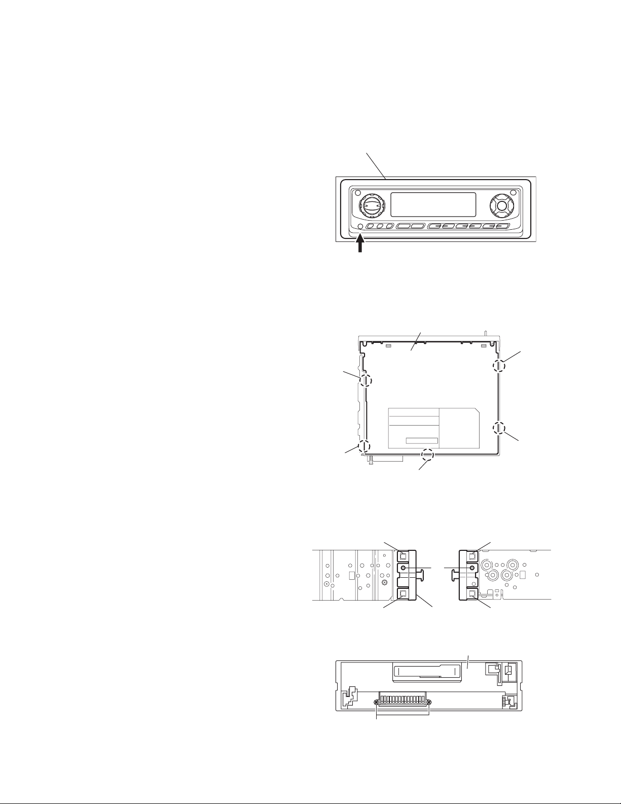
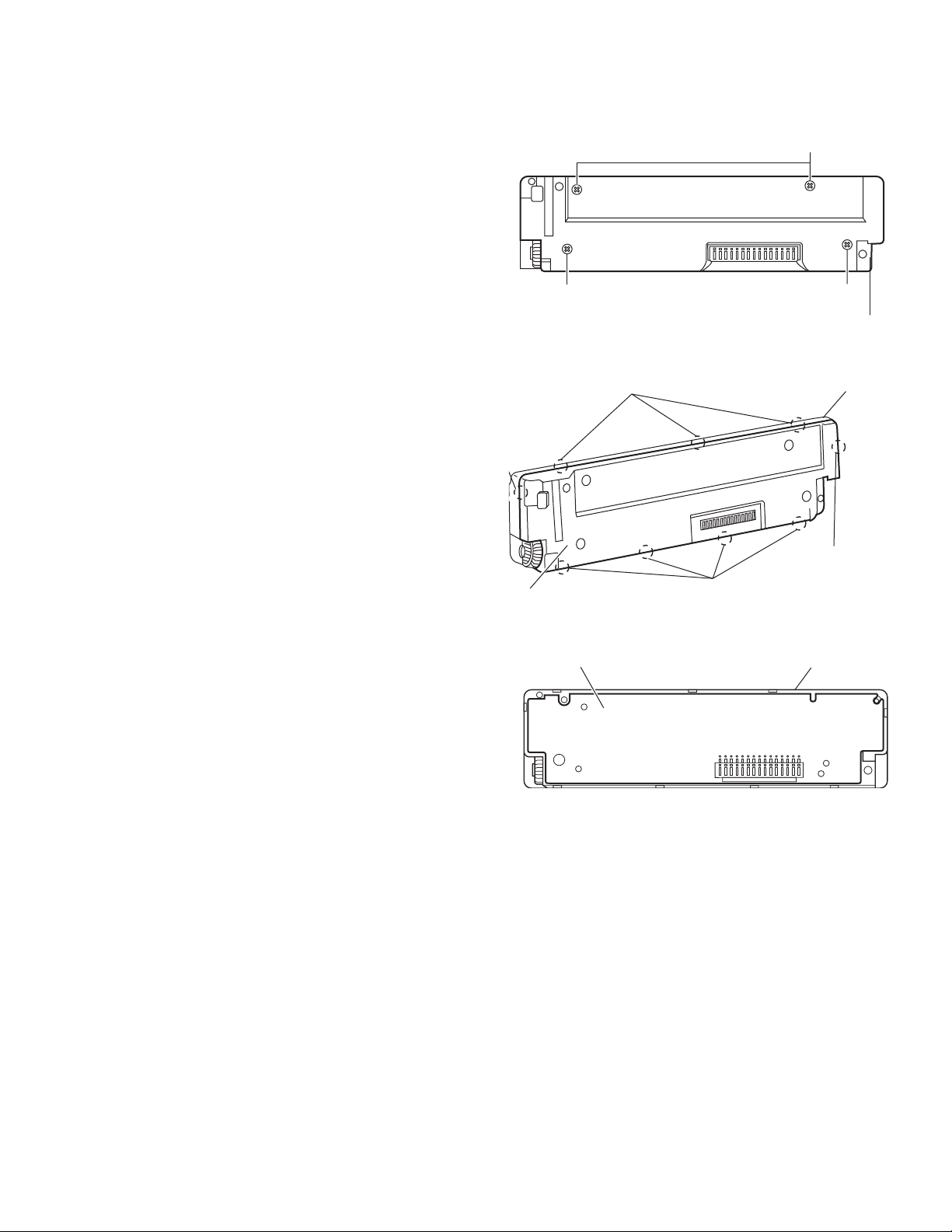
2.1.1 Removing the front panel assembly
(See Fig.1)
(1) Press the rele ase button and remove the front panel as-
sembly.
2.1.2 Removing the bottom cover
(See Fig.2)
• Prior to performing the following procedures, remove the fro nt
panel assembly.
(1) Turn the main body upside down.
(2) Insert a screwdriver under the joints to release the two
joints a on the left side, two joints b on the right side and
joint c on the back side of the main body, then remove the
bottom cover from the main body.
CAUTION:
When releasing the joints using a screwdriver, do not damage
the main board.
Front panel assembly
Release button
Fig.1
Bottom cover
Joint b
Joint a
2.1.3 Removing the front chassis assembly
(See Figs.3 and 4)
• Prior to performing the following procedures, remove the fro nt
panel assembly and bottom cover.
(1) Remo ve the two screws A on the both sides of the main
body. (See Fig.3.)
(2) Remove th e two screws B on the front side of the main
body. (See Fig.4.)
(3) Release the two joints d and two joints e on the both sides
of the main body, then remove the front chassis assembly
toward the front. (See Fig.3.)
Joint a
Joint d
Joint d
B
Joint c
Fig.2
A
Front chassis
Fig.3
Joint b
Joint e
Joint e
1-4 (No.49846)
Fig.4
Page 5
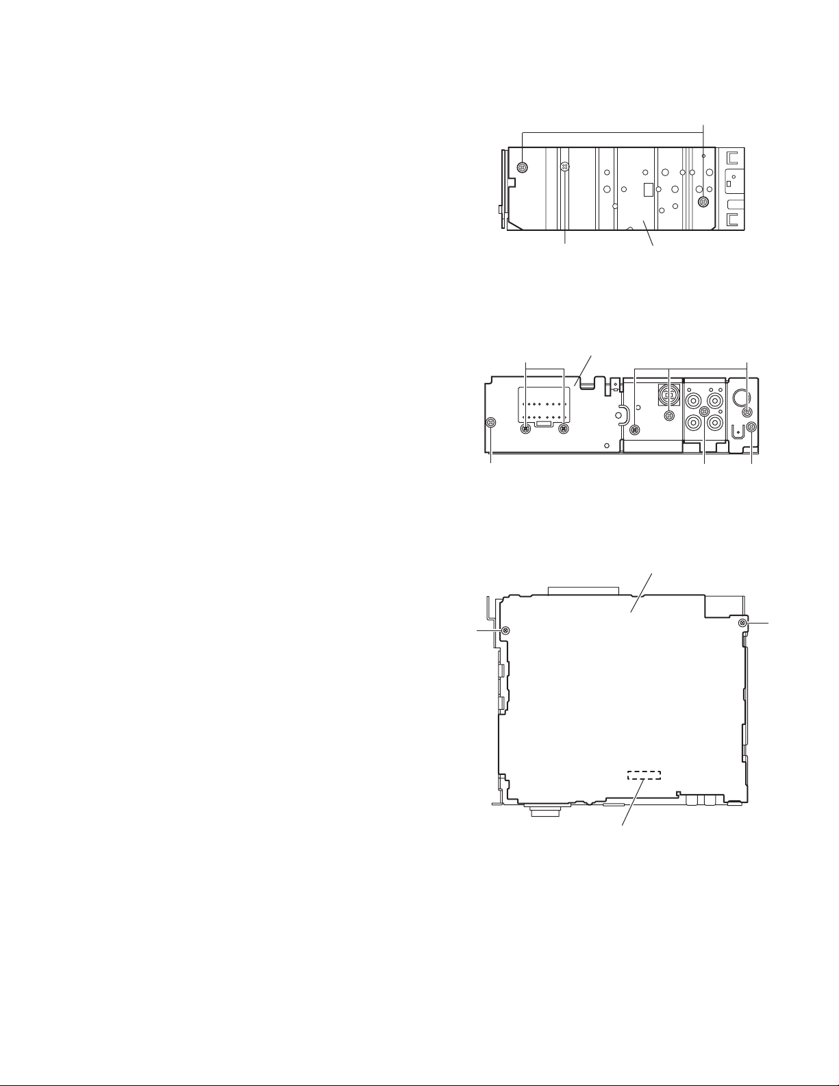
2.1.4 Removing the heat sink
(See Fig.5)
• Prior to performing the following procedure, remove the front
panel assembly.
(1) Remove the two screws C and screw D attaching the heat
sink on the left side of the main body, and remove the heat
sink.
C
2.1.5 Removing the rear panel
(See Fig.6)
• Prior to performing the following procedure, remove the front
panel assembly and bottom cover.
(1) Remove the two screws E, three screws F and three
screws G attaching the rear panel on the back side of the
main body.
2.1.6 Removing the main board
(See Fig.7)
• Prior to performing the following procedures, remove the front
panel assembly, bottom cover, front chassis assembly, heat
sink and rear panel.
(1) Remove the two screws H attaching the main board on the
top chassis.
(2) Disconn ect the connector CP701 on the main board from
the cassette mechanism assembly.
D
F
Rear bracket
EE
H
Heat sink
Fig.5
G
F
Fig.6
Main board
H
CP701
Fig.7
(No.49846)1-5
Page 6

2.1.7 Removing the cassette mechanism assembly
(See Fig.8)
• Prior to performing the following procedures, remove the fro nt
panel assembly, bottom cover, front chassis assembly, heat
sink, rear panel and main board.
(1) Disconnect the wire from the connector CN402 on the
mecha board.
(2) Disconnect the card wire from the connector CN403 on the
mecha board.
(3) Remove the four screws J attaching the cassette mecha-
nism assembly to the top chassis, take out the cassette
mechanism assembly.
Cassette mechanism assembly
H
H
2.1.8 Removing the mecha board
(See Fig.9)
• Prior to performing the following procedures, remove the fro nt
panel assembly, bottom cover, front chassis assembly, heat
sink, rear panel and main board.
(1) Disconnect the wire from the connector CN402 on the
mecha board.
(2) Disconnect the card wire from the connector CN403 on the
mecha board.
(3) Remove the screw K attaching the mecha board.
(4) Bend the hook f in the direction of the arrow 1 and move the
mecha board in the direction of the arrow 2.
(5) Remove the mech a board from the mecha bracket (L) of
the top chassis.
H H
Top chassis
Fig.8
CN402
J
CN401
Fig.9
Mecha board
CN403
1-6 (No.49846)
Page 7
2.1.9 Removing the front board
m
(See Figs.10 to 12)
• Prior to performing the following procedures, remove the front
panel assembly.
(1) Remove the four screws L attaching the rear cover on the
back side of the front panel assembly. (See Fig.10.)
(2) Rele ase the nine joints g, the front panel assembly and
rear cover become separate. (See Fig.11.)
(3) Remove the front board from the front panel assembly.
(See Fig.12.)
L
t g
ar cover
Front board
L
Joints
L
Rear cover
Fig.10
g
Joints g
Fig.11
Front panel assembly
Front panel asse
Joint g
Fig.12
(No.49846)1-7
Page 8

2.2 Cassette mechanism assembly
r
REFERENCE:
Prior to performing the following procedures, turn the mode
gear on the bottom of the body until the respective part comes
to the EJECT position (Refer to Fig.1).
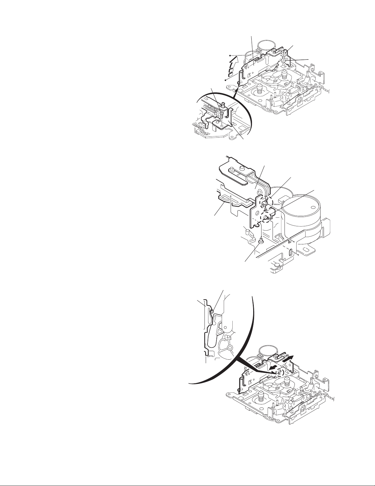
2.2.1 Removing the cassette guide
(See Fig.2)
(1) Turn the mode gear to set to RVS play or subsequent
mode.
(2) Remove the cassette guide from the main chassis while re-
leasing each two joint tabs a in the direction of the arrow.
Mode gea
Fig.1
Cassette guide
2.2.2 Removing the load arm
(See Fig.3)
(1) Remove the E-washer attaching the load arm.
(2) Move the load arm in the direction of the arrow and release
the joint b on the cassette catch.
Load arm
E-washer
Tab a
Tab a
Fig.2
Joint b
Fig.3
1-8 (No.49846)
Page 9

2.2.3 Removing the cassette hanger assembly / cassette holder
r
(See Fig.4 to 7)
(1) Check the mode is set to EJECT. Push down the front part
of the cassette holder and move in the directi on of the arrow to release the joint c.
(2) Move th e rear part of the cassette hanger assembly in the
direction of the arrow to release it from the two joint bosses
d.
(3) Release the holder stabilizer spring from the h ooks e and
f, then pull out from the cassette hanger assembly.
(4) Bri ng up the rear side of the cassette hanger assembly to
release the joint g and h.
(5) Pull ou t the cassette catch from the cassette hanger as-
sembly.
Cassette holder assembly
Side bracket
Joints c
Cassette holder assembly
Fig.4
Boss d
Cassette hanger
assembly
Boss d
Cassette stabilizer spring
Hook e
Cassette holder
assembly
Hook g
Cassette hange
assembly
Hook f
Fig.5
Cassette hanger
assembly
Hook h
Fig.6
Cassette hanger assembly
Cassette catch
Cassette holder assembly
Fig.7
(No.49846)1-9
Page 10
2.2.4 Removing the side bracket assembly
(See Fig.8 to 10)
(1) Remove the screw A attaching the side bracket assembly.
(2) Detach the front side of the side bracket assembly upward
and pull out forward to release the joint i and j in the rear.
CAUTION:
When reassembling, make sure that the boss k of the
main chassis is set in the notch of the load rack under the
side bracket assembly. Do not reattach the load rack on
the boss k.
CAUTION:
After reattaching the side bracket assembly, confirm operation.
Side bracket assembly
Joint i
Joint j
A
Side bracket assembly
Fig.8
Side bracket assembly
Joint i
Joint j
Load rack
Load rack
Boss k
Fig.9
Boss k
1-10 (No.49846)
Fig.10
Page 11
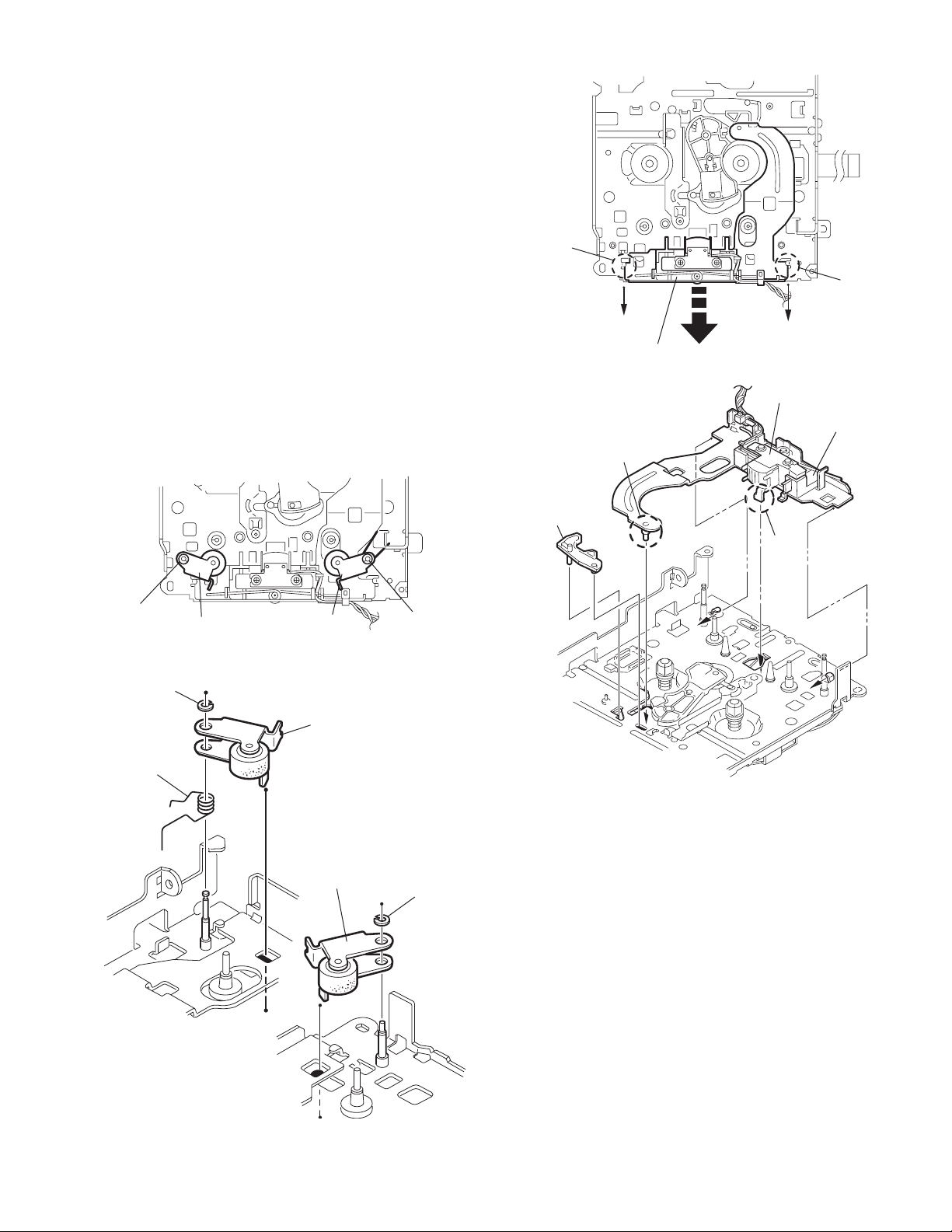
2.2.5 Removing the pinch arm (F) assembly
r
(See Fig.11 and 12)
(1) Remove the polywasher and pull out the pinch arm (F) as-
sembly.
(2) Remove the compul sion spring.
2.2.6 Removing the pinch arm (R) assembly
(See Fig.11 and 12)
(1) Remove the polywasher and pull out the pinch arm (R) as-
sembly.
2.2.7 Removing the slide chassis assembly
(See Fig.13 and 14)
REFERENCE:
It is not necessary to remove the head and the tape guide.
(1) Move th e slid e chassis assembly in the di recti on of the ar-
row to release the two joints l and remove from the main
chassis.
(2) Remove the rack link.
CAUTION:
When reassembling, first reattach the rack link, and next
fit the boss m and hook n of the slide chassis assembly
to the hole of the main chassis, and engage the two joints
l.
Joint l
Joint l
Slide chassis assembly
Fig.13
Head
Tape guide
Boss m
Rack link
Hook n
Polywasher
Polywasher
Compulsion
spring
Pinch arm
(R) assembly
Pinch arm
(F) assembly
Fig.11
Pinch arm (F) assembly
Pinch arm
(R) assembly
Polywashe
Fig.14
Polywasher
Fig.12
(No.49846)1-11
Page 12

2.2.8 Removing the head / tape guide
(See Fig.16 and 17)
REFERENCE:
It is not necessary to remove the slide chassis assembly.
(1) Remov e the band attaching the wire to the head.
(2) Remove the two screws B, the head and the head support
spring.
(3) Remove the pinch arm spring from the tape guide.
(4) Remove the tape guide and the pinch spring arm.
CAUTION:
When reattaching the pinch arm spring, set both end of
it to the pinch spring arm (remarked o).
CAUTION:
When reattaching the head, set the wires into the groove
of the tape guide (Fig.16).
2.2.9 Removing the flywheel assembly (F) & (R)
(See Fig.18 and 19)
REFERENCE:
It is not necessary to remove the slide chassis assembly.
(1) Remove the belt at the bottom.
(2) Remove the two polywashers on the upper side.
(3) Pull out each flywheel assembly downward.
B
Slide chassis assembly
Flywheel assembly (F)
Flywheel assembly (R)
Belt
Fig.17
Polywasher
Polywasher
Head
Head support spring
Tape guide
o
Pinch spring arm
Head
Fig.15
Tape guide
B
Pinch arm spring
Flywheel assembly (F)
Flywheel assembly (R)
Fig.18
o
1-12 (No.49846)
Slid chassis assembly
Fig.16
Page 13
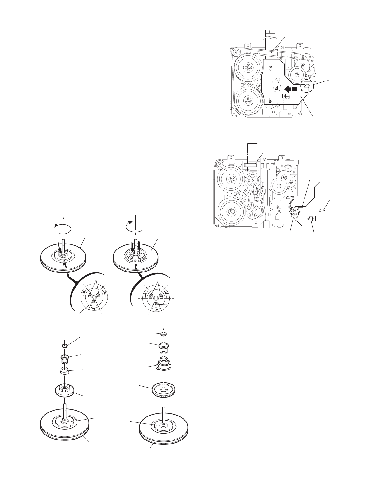
2.2.10 Disassembling the flywheel assembly (F)
r
(See Fig.19 and 20)
(1) Push and turn counterclockwise the spring holder (F) to re-
lease the three joints p on the bottom of the flywheel.
(2) The spring holder (F), the TU spring and the friction gear
play come off.
(3) Remove the pol ywasher and felt.
2.2.11 Disassembling the flywheel assembly (R)
(See Fig.19 and 20)
(1) Push an d turn clockwise the spring holder (R) to release
the three joints q on the bottom of the flywheel.
(2) The spring holder (R), the FF spring and the friction gear
FF come off.
(3) Remove the pol ywasher and the felt.
2.2.12 Removing the reel board
(See Fig.21 and 22)
(1) Remove the tw o screws C attaching the reel board.
(2) Move the reel board in the direction of the arrow to release
the joint r.
(3) Unsol der the wires if necessary.
CAUTION:
When reattaching, confirm operation of the MODE
switch and the ST-BY switch.The mode position between EJECT and ST-BY is optimum for reattaching.Connect the card wire extending from the reel board
to the FFC pad before reattaching the reel board.
FFC pad
C
Joint
Reel board
C
Fig.21
FFC pad
CT-1 switch
MODE switch
Flywheel
assembly (F)
Joint p
Joints p
Fig.19
Polywasher
Spring holder (R)
Spring holder (F)
TU spring
Friction gear FF
Friction gear play
Polywasher
FF spring
Flywheel
assembly (R)
Joints q
Joint q
Soldering
ST-BY switch
Fig.22
Felt
Flywheel assembly (F)
Fig.20
Felt
Flywheel assembly (R)
(No.49846)1-13
Page 14

2.2.13 Removing the gear base arm / gear base link assembly
(See Fig.23 to 25)
(1) Move the gear base arm in the direction of th e arrow.
(2) Insert a slo tted screwdriver to the gear base spring under
the gear base arm, and release the gear base arm upward
from the boss on the gear base assembly.
(3) Remove the gear base arm from the main chassis while re-
leasing the two joints s.
(4) Move the gear base link assemby in the direction of the ar-
row to release the two joints t.
REFERENCE:
When reattaching the gear base arm, make sure that the
boss on the gear base assembly is inside the gear base
spring.
2.2.14 Removing the FFC pad
(See Fig.25 and 27)
(1) Push each joint hook u of the FFC pad and remove toward
the bottom.
Gear base
link assembly
Gear base spring
Joint t
Joint t
Gear base arm
Joints s
Hook u
FFC pad
Hook u
Fig.23
Gear base arm
Gear base link
assembly
Screwdriver
Fig.24
Gear base arm
1-14 (No.49846)
FFC pad
Fig.25
Page 15

2.2.15 Removing the mode gear
r
r
(See Fig.26 and 29)
(1) Remove the polywasher on the bottom and pull out the
mode gear.
2.2.16 Removing the mode switch actuator
(See Fig.26, 27 and 29)
(1) Pull out the mode switch actuator at the bottom.
REFERENCE:
When reattaching the mode switch actuator to the main
chassis, make sure to set on the shaft and insert v into
the slot w.
2.2.17 Removing the direction link / direction plate
(See Fig.27 to 29)
(1) Remove the pol ywasher attaching the direction link.
(2) Bri ng up the direction link to release the three joints x, y
and z at a time.
(3) Move the di recti on pla te in the directio n o f the arrow to re-
lease the two joints a’.
REFERENCE:
When reattaching the direction plate, engage the two
joints a’ and move in the direction of the arrow (Refer to
Fig.28).
REFERENCE:
When reattaching the direction link, move the di rection
plate in the direction of the arrow and engage the three
joint x, y and z at a time (Refer to Fig.29).
2.2.18 Removing the mode rack assembly
(See Fig.27 and 28)
(1) Move the mode rack assembly in the direction of the arrow
to release the two joints b’ and the joint c’.
REFERENCE:
When reattaching, set the two b’ on the bottom of the
mode rack assembly into the slots of the main chassis
and move in the direction of the arrow (See Fig.28).
Direction plate
Direction plate
Joints a'
Joint z
Direction link
Direction plate
Mode switch actuator
Direction link
Fig.26
Slot w
Joint y
Polywasher
Fig.27
Mode rack assembly
Joint b'
Mode gear
Polywashe
Mode rack assembly
Joint x
Joint b'
Joint c'
Joints a'
Fig.28
Direction link
Mode switch actuator
Polywasher
v
Mode gea
Direction plate
Mode rack assembly
Fig.29
(No.49846)1-15
Page 16

2.2.19 Removing the gear base assembly / take up gear / reflector gear
r
(See Fig.30 to 32)
(1) Push in the pin d’ of the gear base assembly on the upper
side of the body and move the reflector gear toward the
bottom, then pull out.
(2) Remove the polywasher on the bottom and pull out the
take up gear.
(3) Move the gear base assembly in the direction of the arrow
to release it from the two slots e’ of the main chassis.
REFERENCE:
The parts are damaged when removed. Please replace
with new ones.
2.2.20 Removing the reel driver / reel spindle
(See Fig.32)
(1) Draw out the reel driver from the shaft on the main chassis
and remove the reel driver spring and the reel spindle respectively.
CAUTION:
The reel driver is damaged when removed. Please replace with a new one.
Gear base assembly
Pin d'
Polywasher
Slot e'
Slot e'
Fig.30
Take up gear
Reflector gear
Reel driver
Reel driver spring
Reel spindle
Main chassis
Reflector gear
Fig.31
Reel driver
Reel driver spring
Reel spindle
Gear base assembly
Slots e’
Take up gea
Polywasher
Fig.32
1-16 (No.49846)
Page 17

2.2.21 Removing the side bracket assembly
(See Fig.33 to 37)
(1) Remove the eje ct cam plate spring.
(2) Push the joi nt f’ through the slot to remove the load rack
downward.
(3) Mov e the eject cam limiter in the direction of the arrow to
release it from the boss g’ of the side bracket assembly and
from the two joints h’.
(4) Move the eject cam plate in the direction of the arrow to re-
lease the joint i’.
CAUTION:
When reassembling, confirm operation of each part before reattaching the eject cam plate spring.
Joint f'
Side bracket assembly
Boss g'
Eject cam plate
Fig.36
Side bracket assembly
Joint i'
Eject cam plate spring
Side bracket assembly
Joint h'
Side bracket
assembly
Boss g'
Boss g'
Load rack
Fig.33
Eject cam limiter
Joint f'
Fig.34
Eject cam limiter
Eject cam plate
Joint i'
Fig.37
Joint h'
Load rack
Joint h'
Eject cam plate
Fig.35
Joint h'
(No.49846)1-17
Page 18

2.2.22 Removing the main motor assembly / sub motor assembly
r
r
r
(See Fig.38 to 40)
(1) Remove the belt at the bottom.
(2) Remov e the polywasher and pull out the mode gear.
(3) Pull out the reduction gear (B).
(4) Remov e the polywasher and pull out the reduction gear
(A).
(5) Remove the two screws attaching the main motor assem-
bly.
(6) Remove the two screws E attaching the sub motor assem-
bly.
(7) Unsolder the wires on the reel board if necessary.
CAUTION:
When reassembling, adjust the length of the wires extending from the sub motor asswmbly by attaching them
to the side of the sub motor assembly with the wires extending from the main motor assembly using a spacer.
Belt
Reduction gear (B)
Reduction gear (B)
E
Mode gear
Polywasher
Fig.38
Main motor
D
assembly
Reduction
gear (A)
Polywashe
Sub moto
assembly
E
Polywasher
Reduction gear (A)
D
Spacer
Main motor assembly
Sub motor assembly
Fig.39
Main motor assembly
Sub motor assembly
Fig.40
Space
1-18 (No.49846)
Page 19

PARTS LIST
[ KS-FX921 ]
* All printed circuit boards and its assemblies are not available as service parts.
Area suffix
KS-FX921
U --------------------- Other Areas
- Contents -
Exploded view of general assembly and parts list (Block No.M1)
Cassette mechanism assembly and parts list (Block No.MP)
Electrical parts list (Block No.01~03)
Packing materials and accessories parts list (Block No.M3)
3- 2
3- 4
3- 8
3-12
No. 49846 3-1
Page 20

KS-FX921
Exploded view of general assmbly and parts list
14
71
72
74
B
A
Main board
15
34
31 24
26
20
21
32
33
28
30
37
27
23 35
15
38
29
25
36
57
22
59
11
19
57
76
77
78
75
14
73
69
70
9
13
16
13
Block No.
67
64
10
M
68
61
M
1
M
65
63
62
LCD1
66
18
19
A
7
8
B
2
5
Mecha control
board
12
1
4
12
17
57
58
12
3
6
4
4
56
Front board
12
43
55
4
54
51
56
45
50
79
44
50
47
46
53
60
52
49
39
40
48
42
41
3-2
Page 21

General assembly
Block No. [M][1][M][M]
Symbol No.
1 FSYH4036-050 SHEET
2 GE20136-001A MECHA BKT(L)
3 FSKL2002-002 MECHA BKT(R)
4 QYSDST2606Z SCREW 2.6mm x 6mm(x4)
5 QYSDST2606Z SCREW 2.6mm x 6mm
6 LV40847-002A SPACER
7 GE10043-011A TOP CHASIS
8 GE40135-001A EARTH PLATE
9 GE30938-003A HEAT SINK
10 GE30393-001A BOTTOM COVER
11 FSMA3005-001 INSULATOR
12 QYSDST2604Z SCREW 2.6mm x 4mm(x4)
13 FSKZ4005-001 SCREW (x2)
14 QYSDST2604Z SCREW 2.6mm x 4mm(x2)
15 QYSDST2606Z SCREW 2.6mm x 6mm(x2)
16 QYSDST2610Z SCREW 2.6mm x 10mm
17 QYSDSF2006M SCREW 2mm x 6mm(x2)
18 GE10064-002A FRONT CHASSIS
19 QYSDST2004M MINI SCREW 2mm x 4mm(x2)
20 VJK3707-001 LIGHT LENS
21 QYSPSGU1745N MINI SCREW 1.7mm x 4.5mm(x2)
22 GE30378-002A OPEN LEVER
23 FSKS3015-001 LOCK LEVER(O.L)
24 VKS3798-002 RELEASE LEVER
25 GE30379-001A LOCK LEVER(TOP)
26 VKS3794-003 LOCK LEVER(L)
27 VKS3795-002 LOCK LEVER(R)
28 VKS5563-001 GEAR
29 VKZ4786-002 OIL DAMPER
30 FSKW4012-001 T.SPRING
31 GE40144-003A T.SPRING
32 VKW5262-001 T.SPRING
33 QYSDSF2006M SCREW 2mm x 6mm
34 VKW5263-002 T.SPRING
35 VKZ4777-001 MINI SCREW
36 GE40164-001A T.SPRING
37 FSJC3014-001 CASS LID
38 VKW4947-002 DOOR SPRING
39 GE10044-014A FRONT PANEL
40 GE30855-003A FINDER ASSY
41 GE30840-002A SEL BTN
42 FSYH4036-032 SHEET
43 GE30537-001A POWER BUTTON
44 GE20124-007A D.FUNC BUTTON
45 GE30581-006A NAV UP BTN
46 GE30582-001A NAV DN BTN
47 GE40148-002A NAV CAP
48 GE40132-001A VOL KNOB
49 GE20129-001A PRESET BUTTON
50 FSYH4036-069 SHEET (x2)
51 GE30387-002A RIM LENS
52 GE30538-003A EJECT BUTTON
53 VKW3001-330 COMP.SPRING
54 GE30547-001A DETACH BUTTON
55 VKW3001-330 COMP.SPRING
56 FSYH4036-081 SPACE R (x3)
57 VKZ4777-001 MINI SCREW (x4)
58 GE10045-001A REAR COVER
59 FSYH4036-035 SHEET
60 GE30389-001A LCD CASE
61 FSJK3028-001 LCD LENS
62 GE40146-001A LIGHTING SHEET
63 FSYH4061-002 LIGHTING SHEET
64 FSKS3013-001 LENS CASE
65 GE30708-001A NAME PLATE
66 QLD0257-001 LCD MODULE
67 QNZ0449-001 RUBBER CONNE
68 QNZ0450-001 RUBBER CONNE
69 QMFZ047-150-T FUSE 15A
70 GE40172-002A IC BRACKET
71 GE40103-002A REG BRACKET
72 GE40107-002A HEAT SINK
Part No. Part Name Description Local
Symbol No.
73 GE30912-002A REAR BRACKET
74 QYSDST2606Z SCREW 2.6mm x 6mm
75 QYSDSF2606Z SCREW 2.6mm x 6mm(x2)
76 QYSDSF2606Z SCREW 2.6mm x 6mm
77 QYSDST2606Z SCREW 2.6mm x 6mm
78 QYSDST2606Z SCREW 2.6mm x 6mm
79 FSKS3017-002 LED HOLDER
Part No. Part Name Description Local
KS-FX921
3-3
Page 22

KS-FX921
Cassette mechanism assembly and parts list
116
27
108
59
24
CDS-802JE3
28
64
Block No.
4
M
M
M
P
94
7
33
10
93
17
45
65
11
106
16
44
111
34
117
37
111
43
40
114
46
39
47
66
38
22
3
66
38
32
51
21
67
114
5
110
31
1
42
61
49
113
109
50
23
63
96
73
91
25
62
35
75
114
26
6
109
2
113
41
60
48
3-4
82
87
84
107
83
86
107
85
111
13
74
72
12
71
Page 23

Cassette mechanism
Block No. [M][P][M][M]
Symbol No.
1 X-0802-1009S MAIN CHASSIS AS
2 X-0802-1002S SLIDE CHASSIS A
3 X-0802-1003S SIDE BKT ASSY
4 X-0802-1004S CASSETTE HANGER
5 X-0802-1005S PINCH ARM F ASS
6 X-0802-1006S PINCH ARM R ASS
7 X-0802-1007S GEARBASE LINK A
10 X-0802-2001S MODE RACK ASSY
11 X-0802-2002S GEAR BASE ASSY
12 1-0802-6001S FLYWHEEL ASSY F
13 1-0802-6002S FLYWHEEL ASSY R
16 X-0802-7002S SUB MOTOR ASSY
17 X-0802-7004S MAIN MOTOR ASSY
21 1-0802-1002S DIRECTION PLATE
22 1-0802-1005S DIRECTION LINK
23 1-0802-1006S CASSETTE HOLDER
24 1-0802-1011S EJECT CAM LIMIT
25 1-0802-1012S HEAD SUPT SPG
26 1-0802-1013S PINCH SPG ARM
27 1-0802-1014S LOAD ARM
28 1-0802-1015S EJECT CAM PLATE
31 1-0101-2056S IDLE PULLEY(A1)
32 1-0802-2001S CASSETTE GUIDE
33 1-0802-2004S GEAR BASE ARM
34 1-0802-2006S LOAD RACK
35 1-0802-2007S TAPE GUIDE
37 1-0802-2009S REDUCTION GEARA
38 1-0802-2010S REEL SPINDLE (x2)
39 1-0802-2011S REEL DRIVER (x2)
40 1-0802-2012S REDUCTION GEARB
41 1-0802-2013S SPG HOLDER F
42 1-0802-2014S SPG HOLDER R
43 1-0802-2015S MODE GEAR
44 1-0802-2016S TAKE UP GEAR
45 1-0802-2017S REFLECTOR GEAR
46 1-0802-2018S RACK LINK
47 1-0802-2019S MODE SW ACTUATR
48 1-0802-2020S FRICTION GEARPL
49 1-0802-2021S FRICTION GEARFF
50 1-0802-2022S CASSETTE CATCH
51 1-0802-2026S FFC PAD
59 1-0802-4001S EJECT CAM PL SP
60 1-0802-4002S TU SPG
61 1-0802-4003S FF SPG
62 1-0802-4004S PINCH ARM SPG
63 1-0802-4005S HOLDER STAB SPG
64 1-0802-4006S HOLDER CUSH SPG
65 1-0802-4007S GEAR BASE SPG
66 1-0802-4008S REEL DRIVER SPG (x2)
67 1-0802-4013S COMPULSION SPG
71 1-0802-5001S BELT
72 1-0802-5002S FELT 7.5*18.5*1
73 1-0802-5003S AZIMUTH SCREW (x2)
74 1-0802-5004S FELT 11*18.5*1
75 1-0050-5023S WTRE CLAMPER
82 1-0802-7001S REEL PCB DL
83 1-0802-7010S
84 1-0802-7003S SW(MICMPU11750)
85 1-0802-7016S FLAT CABLE 10P
86 1-0801-7024S PHOTO SENSOR
87 1-0802-7009S SW(MICMPU12370)
91 1-0802-7007S
93 1-0801-7009-0S M.MOTOR WIRE B
94 1-0801-7009-1S M.MOTOR WIRE R
96 1-0802-7017S JOINT WIRE ASSY
106 2-1032-0025-C2S SCREW (x2)
107 2-13S2-0025-P2S +PLAIN SCR M2 (x2)
108 2-1112-6035-C2S +PLAIN SCR M2.6
109 2-1816-0032-E8S MYLAR WASHER(S) (x2)
110 2-1812-0032-D2S PSW-S 1.2
111 1-0036-5024S PSW(REEL) (x3)
113 2-1821-0040-D1S POLY WASHER (x2)
114 2-1821-0040-D2S PSW-S 2.1 (x3)
116 2-1711-5040-16S E RING
Part No. Part Name Description Local
SW(MATSUCHITA ESE22)
HEAD(MITSUMI P-5344)
Symbol No.
117 2-1031-7030-C2S SCREW (x2)
Part No. Part Name Description Local
KS-FX921
3-5
Page 24

KS-FX921
Grease point 1/2
FG-84M
MEA-512R
MEN-223
SW-902
CFD-409
CFD-250H
EP-56
SW-474B
1
2
3
3-6
5
6
4
Page 25

Grease point 2/2
7
KS-FX921
10
21
27
11
24
28
12
13
33
35
41
39
44
46
42
62
3-7
Page 26

KS-FX921
Electrical parts list
Main board
Symbol No.
IC161 TEA6320T-X IC
IC301 LA47505 IC
IC701 UPD178078GF-618 IC
IC801 HD74HC126FP-X IC
IC901 AN80T05 IC
IC902 KIA7810PI IC
Q1 2SB709A/R/-X TRANSISTOR
Q2 2SB624/4/-X TRANSISTOR
Q3 UN2211-X TRANSISTOR
Q4 UN2211-X TRANSISTOR
Q5 UN2211-X TRANSISTOR
Q31 2SC2412K/R/-X TRANSISTOR
Q32 2SC2412K/R/-X TRANSISTOR
Q241 2SD601A/R/-X TRANSISTOR
Q301 UN2211-X TRANSISTOR
Q321 2SD1781K/QR/-X TRANSISTOR
Q331 2SD1781K/QR/-X TRANSISTOR
Q341 2SD1781K/QR/-X TRANSISTOR
Q351 2SD1781K/QR/-X TRANSISTOR
Q701 2SC2412K/R/-X TRANSISTOR
Q781 UN 2111-X TRANSISTOR
Q782 UN 2111-X TRANSISTOR
Q881 UN2211-X TRANSISTOR
Q891 UN2211-X TRANSISTOR
Q901 2SA1037AK/RS/-X TRANSISTOR
Q902 UN2211-X TRANSISTOR
Q903 UN 2111-X TRANSISTOR
Q904 UN2211-X TRANSISTOR
Q905 2SA1855/RST/-T TRANSISTOR
Q906 UN2211-X TRANSISTOR
Q907 2SA1037AK/RS/-X TRANSISTOR
Q976 2SA1037AK/RS/-X TRANSISTOR
Q977 UN2211-X TRANSISTOR
D1 1SS355-X SI DIODE
D2 1SS355-X SI DIODE
D3 1SS355-X SI DIODE
D4 1SS355-X SI DIODE
D31 UDZS9.1B-X Z DIODE
D32 1SS355-X SI DIODE
D241 1SS355-X SI DIODE
D242 RB160M-30-X SB DIODE
D243 UDZS5.1B-X Z DIODE
D310 1SS355-X SI DIODE
D321 1SS355-X SI DIODE
D331 1SS355-X SI DIODE
D341 1SS355-X SI DIODE
D351 1SS355-X SI DIODE
D701 UDZS6.2B-X Z DIODE
D705 UDZS6.2B-X Z DIODE
D706 UDZS6.2B-X Z DIODE
D707 UDZS6.2B-X Z DIODE
D708 UDZS6.2B-X Z DIODE
D709 UDZS6.2B-X Z DIODE
D710 UDZS6.2B-X Z DIODE
D711 UDZS6.2B-X Z DIODE
D712 UDZS6.2B-X Z DIODE
D713 UDZS6.2B-X Z DIODE
D715 UDZS6.2B-X Z DIODE
D753 SLR-56MC3F LED
D781 1SS355-X SI DIODE
D782 UDZS11B-X Z DIODE
D891 1SS355-X SI DIODE
D892 1SS355-X SI DIODE
D901 1N5401-F64 DIODE
D903 RB160M-30-X SB DIODE
D904 RB160M-30-X SB DIODE
D906 RB160M-30-X SB DIODE
D907 RB160M-30-X SB DIODE
D908 1SS355-X SI DIODE
D909 1SS355-X SI DIODE
Part No. Part Name Description Local
Block No. [0][1][0][0]
Symbol No.
C1 QERF1CM-106Z E CAPACITOR 10uF 16V M
C2 QERF1CM-106Z E CAPACITOR 10uF 16V M
C4 NCB31EK-223X C CAPACIT O R 0.022uF 25V K
C6 NCB31CK-103X C CAPACITOR 0.01uF 16V K
C8 NCS31HJ-121X C CAPACITOR 120pF 50V J
C9 QERF1HM-104Z E CAPACITOR 0.1uF 50V M
C10 NCS31HJ-102X C CAPACITOR 1000pF 50V J
C13 QERF1AM-227Z E CAPACITOR 220uF 10V M
C31 QERF1HM-104Z E CAPACITOR 0.1uF 50V M
C32 QERF1HM-104Z E CAPACITOR 0.1uF 50V M
C33 QERF1HM-225Z E CAPACITOR 2.2uF 50V M
C34 NCS31HJ-102X C CAPACITOR 1000pF 50V J
C35 QERF1AM-227Z E CAPACITOR 220uF 10V M
C81 NCB31EK-223X C CAPACITOR 0.022uF 25V K
C82 QERF1HM-105Z E CAPACITOR 1uF 50V M
C91 NCB31EK-223X C CAPACITOR 0.022uF 25V K
C92 QERF1HM-105Z E CAPACITOR 1uF 50V M
C162 QERF1HM-105Z E CAPACITOR 1uF 50V M
C163 QERF1HM-105Z E CAPACITOR 1uF 50V M
C164 NCB31HK-822X C CAPACITOR 8200pF 50V K
C165 NCB21CK-184X C CAP ACITOR 0.18uF 16V K
C166 NCB31AK-224X C CAPACITOR 0.22uF 10V K
C167 NCB31CK-333X C CAP ACITOR 0.033uF 16V K
C168 NCB31HK-562X C CAPACITOR 5600pF 50V K
C172 QERF1HM-105Z E CAPACITOR 1uF 50V M
C173 QERF1HM-105Z E CAPACITOR 1uF 50V M
C174 NCB31HK-822X C CAPACITOR 8200pF 50V K
C175 NCB21CK-184X C CAP ACITOR 0.18uF 16V K
C176 NCB31AK-224X C CAPACITOR 0.22uF 10V K
C177 NCB31CK-333X C CAP ACITOR 0.033uF 16V K
C178 NCB31HK-562X C CAPACITOR 5600pF 50V K
C181 QERF1HM-225Z E CAPACITOR 2.2uF 50V M
C182 QERF1HM-225Z E CAPACITOR 2.2uF 50V M
C191 QERF1HM-225Z E CAPACITOR 2.2uF 50V M
C192 QERF1HM-225Z E CAPACITOR 2.2uF 50V M
C195 QERF1CM-476Z E CAPACITOR 47uF 16V M
C196 QERF1AM-107Z E CAPACITOR 100uF 10V M
C197 QERF1AM-107Z E CAPACITOR 100uF 10V M
C198 NCB31CK-103X C CAP ACITOR 0.01uF 16V K
C241 QERF1HM-105Z E CAPACITOR 1uF 50V M
C242 QERF1CM-226Z E CAPACITOR 22uF 16V M
C243 NCB31EK-473X C CAPACITOR 0.047uF 25V K
C244 QERF1HM-224Z E CAPACITOR 0.22uF 50V M
C301 QERF1CM-476Z E CAPACITOR 47uF 16V M
C302 QERF1HM-105Z E CAPACITOR 1uF 50V M
C303 QERF1EM-475Z E CAPACITOR 4.7uF 25V M
C304 NCB31HK-223X C CAP ACITOR 0.022uF 50V K
C305 QCS31HJ-471Z C CAPACITOR 470pF 50V J
C313 QERF1HM-474Z E CAPACITOR 0.47uF 50V M
C314 QERF1HM-474Z E CAPACITOR 0.47uF 50V M
C315 QERF1CM-226Z E CAPACITOR 22uF 16V M
C316 NCB31EK-104X C CAPACITOR 0.1uF 25V K
C317 NCB31EK-104X C CAPACITOR 0.1uF 25V K
C318 NCB31EK-104X C CAPACITOR 0.1uF 25V K
C319 NCB31EK-104X C CAPACITOR 0.1uF 25V K
C321 NCS31HJ-471X C CAPACITOR 470pF 50V J
C322 QFVD1HJ-224Z MF CAPA CITOR 0.22uF 50V J
C331 NCS31HJ-471X C CAPACITOR 470pF 50V J
C332 QFVD1HJ-224Z MF CAPA CITOR 0.22uF 50V J
C341 NCS31HJ-471X C CAPACITOR 470pF 50V J
C342 QFVD1HJ-224Z MF CAPA CITOR 0.22uF 50V J
C351 NCS31HJ-471X C CAPACITOR 470pF 50V J
C352 QFVD1HJ-224Z MF CAPA CITOR 0.22uF 50V J
C361 NCB31HK-223X C CAP ACITOR 0.022uF 50V K
C362 NCB31HK-223X C CAP ACITOR 0.022uF 50V K
C701 NCB31EK-104X C CAPACITOR 0.1uF 25V K
C703 NDC31HJ-220X C CAPACITOR 22pF 50V J
C704 NDC31HJ-270X C CAPACITOR 27pF 50V J
C706 NCB31EK-104X C CAPACITOR 0.1uF 25V K
C707 NCB31EK-104X C CAPACITOR 0.1uF 25V K
C708 NCB31AK-224X C CAPACITOR 0.22uF 10V K
C710 QERF1AM-107Z E CAPACITOR 100uF 10V M
C712 NCB31EK-104X C CAPACITOR 0.1uF 25V K
C713 NCB21EK-224X C CAPACITOR 0.22uF 25V K
C714 NCB31EK-104X C CAPACITOR 0.1uF 25V K
Part No. Part Name Description Local
3-8
Page 27

Symbol No.
Part No. Part Name Description Local
Symbol No.
KS-FX921
Part No. Part Name Description Local
C781 QERF1AM-227Z E CAPACITOR 220uF 10V M
C782 QERF1CM-476Z E CAPACITOR 47uF 16V M
C801 NCB31EK-473X C CAPACITOR 0.047uF 25V K
C881 QERF1CM-226Z E CAPACITOR 22uF 16V M
C891 NCB31EK-104X C CAPACITOR 0.1uF 25V K
C901 QEZ0622-338 E CAPACITOR 3300uF
C902 QERF1CM-106Z E CAPACITOR 10uF 16V M
C903 QERF1AM-227Z E CAPACITOR 220uF 10V M
C904 QERF1AM-227Z E CAPACITOR 220uF 10V M
C905 QERF1CM-106Z E CAPACITOR 10uF 16V M
C906 QERF1CM-106Z E CAPACITOR 10uF 16V M
C907 QERF1CM-106Z E CAPACITOR 10uF 16V M
C908 NCS31HJ-471X C CAPACITOR 470pF 50V J
C909 NCB31EK-104X C CAPACITOR 0.1uF 25V K
C910 NCB21CK-334X C CAPACITOR 0.33uF 16V K
C911 NCB31EK-104X C CAPACITOR 0.1uF 25V K
C912 QERF1AM-227Z E CAPACITOR 220uF 10V M
C913 NCB31EK-104X C CAPACITOR 0.1uF 25V K
C914 QERF1CM-106Z E CAPACITOR 10uF 16V M
C917 QERF1CM-106Z E CAPACITOR 10uF 16V M
R1 NRSA63J-100X MG RESISTOR 10Ω 1/16W J
R2 NRSA63J-103X MG RESISTOR 10kΩ 1/16W J
R3 NRSA63J-103X MG RESISTOR 10kΩ 1/16W J
R4 NRSA63J-222X MG RESISTOR 2.2kΩ 1/16W J
R5 NRSA63J-102X MG RESISTOR 1kΩ 1/16W J
R6 NRSA63J-0R0X MG RESISTOR 0Ω 1/16W J
R7 NRSA63J-103X MG RESISTOR 10kΩ 1/16W J
R8 NRSA63J-822X MG RESISTOR 8.2kΩ 1/16W J
R9 NRSA63J-223X MG RESISTOR 22kΩ 1/16W J
R13 NRSA63J-103X MG RESISTOR 10kΩ 1/16W J
R22 NRS181J-0R0X MG RESISTOR 0Ω 1/8W J
R24 NRSA63J-0R0X MG RESISTOR 0Ω 1/16W J
R25 NRS181J-6R8X MG RESISTOR 6.8Ω 1/8W J
R26 NRS181J-0R0X MG RESISTOR 0Ω 1/8W J
R31 NRSA02J-102X MG RESISTOR 1kΩ 1/10W J
R32 NRSA63J-102X MG RESISTOR 1kΩ 1/16W J
R33 NRSA63J-102X MG RESISTOR 1kΩ 1/16W J
R34 NRSA02J-103X MG RESISTOR 10kΩ 1/10W J
R35 NRSA63J-152X MG RESISTOR 1.5kΩ 1/16W J
R36 NRSA02J-471X MG RESISTOR 470Ω 1/10W J
R81 NRSA63J-122X MG RESISTOR 1.2kΩ 1/16W J
R82 NRSA63J-472X MG RESISTOR 4.7kΩ 1/16W J
R91 NRSA63J-122X MG RESISTOR 1.2kΩ 1/16W J
R92 NRSA63J-472X MG RESISTOR 4.7kΩ 1/16W J
R161 NRSA63J-223X MG RESISTOR 22kΩ 1/16W J
R162 NRSA63J-222X MG RESISTOR 2.2kΩ 1/16W J
R165 NRSA63J-473X MG RESISTOR 47kΩ 1/16W J
R166 NRSA63J-473X MG RESISTOR 47kΩ 1/16W J
R171 NRSA63J-223X MG RESISTOR 22k
R172 NRSA63J-222X MG RESISTOR 2.2kΩ 1/16W J
R175 NRSA63J-473X MG RESISTOR 47k
R176 NRSA63J-473X MG RESISTOR 47k
R177 NRS181J-100X MG RESISTOR 10Ω 1/8W J
R241 NRSA63J-154X MG RESISTOR 150k
R242 NRSA63J-154X MG RESISTOR 150k
R243 NRSA63J-184X MG RESISTOR 180kΩ 1/16W J
R244 NRSA63J-183X MG RESISTOR 18k
R245 NRSA63J-123X MG RESISTOR 12kΩ 1/16W J
R246 NRSA63J-470X MG RESISTOR 47
R247 NRSA63J-102X MG RESISTOR 1k
R248 NRSA63J-683X MG RESISTOR 68kΩ 1/16W J
R249 NRSA63J-473X MG RESISTOR 47k
R250 NRSA63J-221X MG RESISTOR 220
R303 NRSA63J-103X MG RESISTOR 10kΩ 1/16W J
R305 NRSA63J-103X MG RESISTOR 10k
R321 NRSA63J-273X MG RESISTOR 27k
R323 NRSA02J-102X MG RESISTOR 1k
R324 NRSA02J-101X MG RESISTOR 100
R325 NRSA63J-222X MG RESISTOR 2.2kΩ 1/16W J
R331 NRSA63J-273X MG RESISTOR 27k
R333 NRSA02J-102X MG RESISTOR 1k
R334 NRSA02J-101X MG RESISTOR 100Ω 1/10W J
R335 NRSA63J-222X MG RESISTOR 2.2k
R341 NRSA63J-273X MG RESISTOR 27k
R343 NRSA02J-102X MG RESISTOR 1kΩ 1/10W J
R344 NRSA02J-101X MG RESISTOR 100
R345 NRSA63J-222X MG RESISTOR 2.2k
Ω
1/16W J
Ω
1/16W J
Ω
1/16W J
Ω
1/16W J
Ω
1/16W J
Ω
1/16W J
Ω
1/16W J
Ω
1/16W J
Ω
1/16W J
Ω
1/16W J
Ω
1/16W J
Ω
1/16W J
Ω
1/10W J
Ω
1/10W J
Ω
1/16W J
Ω
1/10W J
Ω
1/16W J
Ω
1/16W J
Ω
1/10W J
Ω
1/16W J
R351 NRSA63J-273X MG RESISTOR 27kΩ 1/16W J
R353 NRSA02J-102X MG RESISTOR 1kΩ 1/10W J
R354 NRSA02J-101X MG RESISTOR 100Ω 1/10W J
R355 NRSA63J-222X MG RESISTOR 2.2kΩ 1/16W J
R702 NRSA63J-473X MG RESISTOR 47kΩ 1/16W J
R703 NRSA63J-473X MG RESISTOR 47k
R704 NRSA63J-472X MG RESISTOR 4.7k
R705 NRSA63J-472X MG RESISTOR 4.7kΩ 1/16W J
R706 NRSA63J-472X MG RESISTOR 4.7kΩ 1/16W J
R707 NRSA63J-472X MG RESISTOR 4.7kΩ 1/16W J
R708 NRSA63J-332X MG RESISTOR 3.3kΩ 1/16W J
R709 NRSA63J-332X MG RESISTOR 3.3kΩ 1/16W J
R710 NRSA63J-473X MG RESISTOR 47kΩ 1/16W J
R711 NRSA63J-563X MG RESISTOR 56kΩ 1/16W J
R712 NRSA63J-472X MG RESISTOR 4.7kΩ 1/16W J
R713 NRSA63J-472X MG RESISTOR 4.7kΩ 1/16W J
R714 NRSA63J-472X MG RESISTOR 4.7kΩ 1/16W J
R717 NRSA63J-473X MG RESISTOR 47kΩ 1/16W J
R718 NRSA63J-683X MG RESISTOR 68kΩ 1/16W J
R719 NRSA63J-103X MG RESISTOR 10kΩ 1/16W J
R720 NRSA63J-103X MG RESISTOR 10k
R721 NRSA63J-103X MG RESISTOR 10k
R723 NRSA63J-103X MG RESISTOR 10kΩ 1/16W J
R724 NRSA63J-0R0X MG RESISTOR 0Ω 1/16W J
R725 NRSA63J-473X MG RESISTOR 47kΩ 1/16W J
R726 NRSA63J-472X MG RESISTOR 4.7kΩ 1/16W J
R727 NRSA63J-473X MG RESISTOR 47kΩ 1/16W J
R731 NRSA63J-473X MG RESISTOR 47kΩ 1/16W J
R732 NRSA63J-472X MG RESISTOR 4.7kΩ 1/16W J
R733 NRSA63J-472X MG RESISTOR 4.7kΩ 1/16W J
R734 NRSA63J-472X MG RESISTOR 4.7kΩ 1/16W J
R735 NRSA63J-103X MG RESISTOR 10kΩ 1/16W J
R736 NRSA63J-103X MG RESISTOR 10kΩ 1/16W J
R739 NRSA63J-103X MG RESISTOR 10kΩ 1/16W J
R741 NRSA63J-473X MG RESISTOR 47kΩ 1/16W J
R742 NRSA63J-473X MG RESISTOR 47kΩ 1/16W J
R743 NRSA63J-473X MG RESISTOR 47kΩ 1/16W J
R744 NRSA63J-101X MG RESISTOR 100Ω 1/16W J
R746 NRSA63J-473X MG RESISTOR 47kΩ 1/16W J
R752 NRSA63J-0R0X MG RESISTOR 0Ω 1/16W J
R753 NRS181J-511X MG RESISTOR 510Ω 1/8W J
R755 NRSA63J-103X MG RESISTOR 10kΩ 1/16W J
R756 NRSA63J-473X MG RESISTOR 47kΩ 1/16W J
R757 NRSA63J-473X MG RESISTOR 47kΩ 1/16W J
R758 NRSA63J-104X MG RESISTOR 100kΩ 1/16W J
R801 NRSA63J-104X MG RESISTOR 100kΩ 1/16W J
R802 NRSA63J-104X MG RESISTOR 100kΩ 1/16W J
R803 NRSA63J-101X MG RESISTOR 100Ω 1/16W J
R804 NRSA63J-334X MG RESISTOR 330kΩ 1/16W J
R805 NRSA63J-334X MG RESISTOR 330k
R806 NRSA63J-104X MG RESISTOR 100kΩ 1/16W J
R807 NRSA63J-101X MG RESISTOR 100
R808 NRSA63J-223X MG RESISTOR 22k
R809 NRSA63J-103X MG RESISTOR 10kΩ 1/16W J
R810 NRSA63J-104X MG RESISTOR 100k
R881 NRSA63J-472X MG RESISTOR 4.7k
R882 NRSA63J-473X MG RESISTOR 47kΩ 1/16W J
R891 NRSA63J-102X MG RESISTOR 1k
R892 NRSA63J-473X MG RESISTOR 47kΩ 1/16W J
R901 QRE142J-470X C RESISTOR 47
R902 NRSA02J-682X MG RESISTOR 6.8k
R903 NRSA02J-113X MG RESISTOR 11kΩ 1/10W J
R904 NRSA63J-473X MG RESISTOR 47k
R905 NRSA63J-102X MG RESISTOR 1k
R906 NRSA63J-473X MG RESISTOR 47kΩ 1/16W J
R907 NRSA63J-102X MG RESISTOR 1k
R908 NRSA63J-473X MG RESISTOR 47k
R909 NRSA63J-102X MG RESISTOR 1k
R910 NRSA63J-103X MG RESISTOR 10k
R911 NRSA63J-101X MG RESISTOR 100Ω 1/16W J
R912 NRSA63J-0R0X MG RESISTOR 0
R913 NRS181J-222X MG RESISTOR 2.2k
R914 NRS181J-222X MG RESISTOR 2.2kΩ 1/8W J
R976 NRSA02J-123X MG RESISTOR 12k
R977 NRSA02J-273X MG RESISTOR 27k
L1 QQL244J-4R7Z INDUCTIOR 4.7uH J
L901 QQR0703-001 CHOKE COIL
Ω
1/16W J
Ω
1/16W J
Ω
1/16W J
Ω
1/16W J
Ω
1/16W J
Ω
1/16W J
Ω
1/16W J
Ω
1/16W J
Ω
1/16W J
Ω
1/16W J
Ω
1/4W J
Ω
1/10W J
Ω
1/16W J
Ω
1/16W J
Ω
1/16W J
Ω
1/16W J
Ω
1/16W J
Ω
1/16W J
Ω
1/16W J
Ω
1/8W J
Ω
1/10W J
Ω
1/10W J
3-9
Page 28

KS-FX921
Symbol No.
Part No. Part Name Description Local
Symbol No.
Part No. Part Name Description Local
L902 QQL244J-470Z COIL 47uH J
CJ321 QNN0490-001 PIN JACK
CN701 QNZ0007-002 CAR CONNECTOR
CN901 QNZ0611-001 16P CONNECTOR
CP401 QGB1214J1-18S CONNECTOR B-B (1-18)
J1 QNB0100-002 CAR ANT JACK
J801 QNZ0095-001 CONNECTOR
S701 QSQ1A11-V06Z TACT SW I/M
S702 QSW0451-001 DETECT SW
S703 QSW0451-001 DETECT SW
TU1 QAU0281-001 TUNER PACK
X701 QAX0406-001Z CRYSTAL 4.500MHz
Front board
Block No. [0][2][0][0]
Symbol No.
IC601 LC75873NW IC
IC602 GP1UM261XK IR DETECT UNIT 38kHz
Q641 2SB624/4/-X TRANSISTOR
Q642 UN2211-X TRANSISTOR
D601 SML-310LT/MN/-X LED
D602 LNJ308G81/1-3/X LED
D603 LNJ308G81/1-3/X LED
D604 LNJ308G81/1-3/X LED
D605 LNJ308G81/1-3/X LED
D606 LNJ308G81/1-3/X LED
D607 LNJ308G81/1-3/X LED
D608 LNJ308G81/1-3/X LED
D609 LNJ308G81/1-3/X LED
D610 CL-190UB-X-X BLUE LED
D611 CL-190UB-X-X BLUE LED
D612 LNJ308G81/1-3/X LED
D613 LNJ308G81/1-3/X LED
D614 LNJ308G81/1-3/X LED
D615 LNJ308G81/1-3/X LED
D616 LNJ308G81/1-3/X LED
D617 LNJ308G81/1-3/X LED
D618 LNJ308G81/1-3/X LED
D619 LNJ308G81/1-3/X LED
D620 LNJ308G81/1-3/X LED
D621 LNJ308G81/1-3/X LED
D622 LNJ308G81/1-3/X LED
D623 LNJ308G81/1-3/X LED
D624 LNJ308G81/1-3/X LED
D625 LNJ308G81/1-3/X LED
D641 NSPW310BS/BRS/ LED
D642 NSPW310BS/BRS/ LED
D643 NSPW310BS/BRS/ LED
D651 UDZS5.1B-X Z DIODE
D652 1SS355-X SI DIODE
D653 1SS355-X SI DIODE
D654 1SS355-X SI DIODE
D655 1SS355-X SI DIODE
D656 1SS355-X SI DIODE
D657 1SS355-X SI DIODE
D658 1SS355-X SI DIODE
D659 UDZS5.6B-X Z DIODE 1.5kΩ 1/10W J
C601 NBE20JM-475X TA E CAPACITOR 4.7uF 6.3V M
C602 NCB31HK-103X C CAPACITOR 0.01uF 50V K
C603 NCS31HJ-221X C CAPACITOR 220pF 50V J
C604 NCB31AK-224X C CAPACITOR 0.22uF 10V K
C605 NCB31AK-224X C CAPACITOR 0.22uF 10V K
C606 NCB31EK-104X C CAPACITOR 0.1uF 25V K
R601 NRSA63J-821X MG RESISTOR 820
R602 NRSA63J-821X MG RESISTOR 820Ω 1/16W J
R603 NRSA63J-122X MG RESISTOR 1.2k
R604 NRSA63J-182X MG RESISTOR 1.8k
Part No. Part Name Description Local
Ω
1/16W J
Ω
1/16W J
Ω
1/16W J
R605 NRSA63J-272X MG RESIS TOR 2.7kΩ 1/16W J
R606 NRSA63J-392X MG RESIS TOR 3.9kΩ 1/16W J
R607 NRSA63J-821X MG RESIS TOR 820Ω 1/16W J
R608 NRSA63J-821X MG RESIS TOR 820Ω 1/16W J
R609 NRSA63J-122X MG RESIS TOR 1.2kΩ 1/16W J
R610 NRSA63J-182X MG RESIS TOR 1.8k
R611 NRSA63J-272X MG RESIS TOR 2.7k
R612 NRSA63J-821X MG RESIS TOR 820Ω 1/16W J
R613 NRSA63J-821X MG RESIS TOR 820Ω 1/16W J
R614 NRSA63J-122X MG RESIS TOR 1.2kΩ 1/16W J
R620 NRS181J-821X MG RESISTOR 820Ω 1/8W J
R621 NRSA02J-122X MG RESIS TOR 1.2kΩ 1/10W J
R622 NRSA02J-122X MG RESIS TOR 1.2kΩ 1/10W J
R623 NRSA02J-122X MG RESIS TOR 1.2kΩ 1/10W J
R624 NRSA02J-122X MG RESIS TOR 1.2kΩ 1/10W J
R625 NRSA02J-561X MG RESIS TOR 560Ω 1/10W J
R626 NRSA02J-561X MG RESIS TOR 560Ω 1/10W J
R627 NRSA02J-511X MG RESISTOR 510Ω 1/10W J
R628 NRSA02J-511X MG RESISTOR 510Ω 1/10W J
R629 NRSA02J-561X MG RESIS TOR 560Ω 1/10W J
R630 NRSA02J-561X MG RESIS TOR 560
R631 NRSA02J-561X MG RESIS TOR 560
R632 NRSA02J-561X MG RESIS TOR 560Ω 1/10W J
R633 NRSA02J-122X MG RESIS TOR 1.2kΩ 1/10W J
R634 NRSA02J-122X MG RESIS TOR 1.2kΩ 1/10W J
R635 NRSA02J-122X MG RESIS TOR 1.2kΩ 1/10W J
R636 NRSA02J-122X MG RESIS TOR 1.2kΩ 1/10W J
R637 NRSA02J-561X MG RESIS TOR 560Ω 1/10W J
R638 NRSA02J-561X MG RESIS TOR 560Ω 1/10W J
R639 NRSA02J-182X MG RESIS TOR 1.8kΩ 1/10W J
R640 NRSA02J-182X MG RESIS TOR 1.8kΩ 1/10W J
R641 NRS181J-431X MG RESISTOR 430Ω 1/8W J
R642 NRS181J-431X MG RESISTOR 430Ω 1/8W J
R643 NRS181J-431X MG RESISTOR 430Ω 1/8W J
R644 NRS181J-471X MG RESISTOR 470Ω 1/8W J
R645 NRSA63J-473X MG RESIS TOR 47kΩ 1/16W J
R646 NRS181J-102X MG RESISTOR 1kΩ 1/8W J
R650 NRSA63J-101X MG RESIS TOR 100Ω 1/16W J
R651 NRSA63J-473X MG RESIS TOR 47kΩ 1/16W J
R652 NRSA63J-473X MG RESIS TOR 47kΩ 1/16W J
R653 NRS181J-102X MG RESISTOR 1kΩ 1/8W J
R654 NRSA63J-221X MG RESIS TOR 220Ω 1/16W J
R655 NRSA63J-394X MG RESIS TOR 390kΩ 1/16W J
R656 NRSA63J-334X MG RESIS TOR 330kΩ 1/16W J
R657 NRSA63J-103X MG RESIS TOR 10kΩ 1/16W J
R658 NRSA63J-103X MG RESIS TOR 10kΩ 1/16W J
R659 NRSA63J-103X MG RESIS TOR 10kΩ 1/16W J
R660 NRSA63J-103X MG RESIS TOR 10kΩ 1/16W J
R661 NRSA63J-470X MG RESIS TOR 47Ω 1/16W J
R662 NRSA63J-332X MG RESIS TOR 3.3k
R663 NRSA63J-332X MG RESIS TOR 3.3kΩ 1/16W J
R664 NRSA63J-332X MG RESIS TOR 3.3k
CN601 QNZ0006-001 CAR CONNECTOR
EN601 QSW0793-001 ROTARY ENCODER
S601 NSW0124-001X TA CT SW
S602 NSW0124-001X TA CT SW
S603 NSW0124-001X TA CT SW
S604 NSW0124-001X TA CT SW
S605 NSW0124-001X TA CT SW
S606 NSW0124-001X TA CT SW
S607 NSW0124-001X TA CT SW
S608 NSW0124-001X TA CT SW
S609 NSW0124-001X TA CT SW
S610 NSW0124-001X TA CT SW
S611 NSW0124-001X TA CT SW
S612 NSW0124-001X TA CT SW
S613 NSW0124-001X TA CT SW
S614 NSW0124-001X TA CT SW
S615 NSW0124-001X TA CT SW
S616 NSW0124-001X TA CT SW
S617 NSW0124-001X TA CT SW
Ω
1/16W J
Ω
1/16W J
Ω
1/10W J
Ω
1/10W J
Ω
1/16W J
Ω
1/16W J
3-10
Page 29

Mecha control board
Block No. [0][3][0][0]
Symbol No.
IC401 CXA2560Q IC
IC402 LB1641 IC
Q402 UN2211-X TRANSISTOR
Q403 2SB1322/RS/-T TRANSISTOR
D401 MA3047/H/-X Z DIODE
D402 1A3G-T1 SI DIODE
C401 NDC31HJ-101X C CAPACITOR 100pF 50V J
C402 NDC31HJ-101X C CAPACITOR 100pF 50V J
C403 NDC31HJ-101X C CAPACITOR 100pF 50V J
C404 NDC31HJ-101X C CAPACITOR 100pF 50V J
C405 NDC31HJ-101X C CAPACITOR 100pF 50V J
C406 NDC31HJ-101X C CAPACITOR 100pF 50V J
C407 NDC31HJ-101X C CAPACITOR 100pF 50V J
C408 NDC31HJ-101X C CAPACITOR 100pF 50V J
C409 QEKJ1CM-226Z E CAPACITOR 22uF 16V M
C410 QFV61HJ-153Z MF CAPACITOR 0.015uF 50V J
C411 QFV61HJ-153Z MF CAPACITOR 0.015uF 50V J
C412 NCB31EK-104X C CAPACITOR 0.1uF 25V K
C413 NCB31EK-104X C CAPACITOR 0.1uF 25V K
C414 QEKJ1CM-226Z E CAPACITOR 22uF 16V M
C415 NCB31EK-103X C CAPACITOR 0.01uF 25V K
C416 QFVD1HJ-104Z MF CAPACITOR 0.1uF 50V J
C417 QFVD1HJ-104Z MF CAPACITOR 0.1uF 50V J
C418 NDC31HJ-221X C CAPACITOR 220pF 50V J
C419 QEKJ1HM-474Z E CAPACITOR 0.47uF 50V M
C421 NCB31HK-183X C CAPACITOR 0.018uF 50V K
C422 NCB31EK-104X C CAPACITOR 0.1uF 25V K
C423 QERF1CM-106Z E CAPACITOR 10uF 16V M
C424 NCB31EK-104X C CAPACITOR 0.1uF 25V K
C425 NCB31HK-103X C CAPACITOR 0.01uF 50V K
R401 NRS181J-681X MG RESISTOR 680Ω 1/8W J
R402 NRSA63J-104X MG RESISTOR 100kΩ 1/16W J
R403 NRSA63J-104X MG RESISTOR 100kΩ 1/16W J
R404 NRSA63J-104X MG RESISTOR 100kΩ 1/16W J
R405 NRSA63J-104X MG RESISTOR 100kΩ 1/16W J
R406 NRSA63J-181X MG RESISTOR 180Ω 1/16W J
R407 NRSA63J-181X MG RESISTOR 180Ω 1/16W J
R412 NRSA02J-101X MG RESISTOR 100Ω 1/10W J
R413 NRSA63J-183X MG RESISTOR 18kΩ 1/16W J
R414 NRSA63J-392X MG RESISTOR 3.9kΩ 1/16W J
R415 NRSA63J-223X MG RESISTOR 22kΩ 1/16W J
R416 NRSA63J-155X MG RESISTOR 1.5M
R417 NRSA63J-103X MG RESISTOR 10kΩ 1/16W J
R418 NRSA63J-153X MG RESISTOR 15k
R422 NRSA02J-332X MG RESISTOR 3.3k
R423 NRS181J-473X MG RESISTOR 47kΩ 1/8W J
R424 NRSA02J-332X MG RESISTOR 3.3k
R425 NRS181J-330X MG RESISTOR 33
VR401 QVP0009-333Z TRIM RESISTOR 33k
VR402 QVP0009-333Z TRIM RESISTOR 33k
CN401 QGB1214K1-18S CONNECTOR B-B (1-18)
CN402 QGA2001C1-06 CONNECTOR W-B (1-6)
CN403 QGF1219F1-10S CONNECTOR FFC/FPC (1-10)
Part No. Part Name Description Local
Ω
1/16W J
Ω
1/16W J
Ω
1/10W J
Ω
1/10W J
Ω
1/8W J
Ω
Ω
KS-FX921
3-11
Page 30

KS-FX921
Packing materials and accessories parts list
P6
Block No.
P1
A1
A2
P7
M
3
M
M
P7
A10
KIT
A3A4
:
A9
P2
A6A5 A7
P5
A13
P3
A11
A12
3-12
P4
A8
Page 31

Packing and accessories
Block No. [M][3][M][M]
Symbol No.
Part No. Part Name Description Local
A 1 GET0128-001A INST BOOK ENG ARA CHI THA
A 2 GET0128-002A INSTALL MANUAL ENG ARA CHI THA
A 3 VKZ4027-202 PLUG NUT
A 4 VKH4871-001SS M OU NT BOLT
A 5 VKZ4328-001 LOCK NUT
A 6 WNS5000Z WASHER
A 7 GE40130-001A HOOK (x2)
A 8 FSJB3001-30C HARD CASE
A 9 GE20137-003A MOUNTING SLEEVE
A 10 GE20149-007A TRIM PLATE
A 11 RM-RK50 REMOCON UNIT
A 12 ------------------- BATTERY
A 13 QAM0308-001 16 CORD ASSY
KIT KSFX480K-SCR EW1 SCREW PARTS KIT A3 to A7
P 1 FSPG4002-001 POLY BAG
P 2 QPA00801205 POLY BAG 8cm x 12cm
P 3 QPA01003003 POLY BAG 10cm x 30cm
P 4 FSYH4036-068 SHEET
P 5 QPC03004315P POLY BAG 30cm x 43cm
P 6 GE30709-001A CARTON
P 7 GE10070-001A EPS CUSHION
KS-FX921
3-13
Page 32

KS-FX921
SCHEMATIC DIAGRAMS
CASSETTE RECEIVER
KS-FX921
CD-ROM No.SML200305
Contents
Block diagram
Standard schematic diagrams
Printed circuit boards
SOUND
ATT
U
SOURCE
F
R
D
VOL
VOL
Area Suffix
U --------------------- Other Areas
2-1
2-2
2-5 to 7
COPYRIGHT 2003 VICTOR COMPANY OF JAPAN, LTD.
No.49846SCH
2003/05
Page 33

KS-FX921
Safety precaution
!
Burrs formed during molding may be left over on some parts of the chassis. Therefore,
pay attention to such burrs in the case of preforming repair of this system.
2-4
Page 34

Block diagram
KS-FX921
LINE OUT
5
TU.L
TU.R
J1
ANT
TU1
FM/AM
TUNER
IC161
TAPE.L
PHOTO
PHOTO
REEL
4
MAIN
MOTOR
SUB
MOTOR
3
SWITCH
REEL
MOTOR
SUBMO+
SUBMO -
TAPE IN
STAND BY
MODE
CN403 CN402
SUBMO+
SUBMO -
MOTOR
REEL
MODE
TAPEIN
STANDBY
IC401
HEAD
IC402
MOTOR
DRIVER
SUBMO+
SUBMO -
Lch
Rch
FF/REW
MSOUT
F/R
DOLBY
CN401
AMP
FWD L,FWD R
P. B .
REW L,REW R
TAPE.R
CP401
FF/REW
MS,F/R
DOLBY
MOTOR
SUBMO+
SUBMOTAPEIN
STDBY
MODE
REEL
HEAD
MONO
SD/ST
S.METER
AM/FM
IFC
FMOSC
EQ
IC701
MICON
JBUS.SI
JBUS.SO
JBUS.IO
JBUS.INT
JBUS.SCK
IC801
E.VOLUME
SCL
SDA
CH.L
CH.R
J-BUS
CJ321
FRONT LEFT
FRONT RIGHT
REAR LEFT
REAR RIGHT
REGULATOR
OUTLF
OUTRF
OUTLR
OUTRR
IC901
IC301
POWER AMP
LFOUT+
LFOUTLROUT+
LROUTRFOUT+
RFOUTRROUT+
RROUT-
2
REMOCON
LCDDA
LCDCL
LCDCE
KEY0 to KEY2
COM1 to COM3
S1 to S68
LCD1
KEY0 to KEY2 REMOCON
KEY MTRIX
S601 to S617
IC601
LCD
DRIVER
IC602
REMOCON
RECEIVER
LCDDA
LCDCL
LCDCE
ENC1,ENC2
EN601
ENCODER
CN601
CN701
SI/SO
SCK
CJ 801
CD-CH
EACH BLOCK
CN901
SKP
BATT
1
AB CD E F G
2-1
Page 35

Standard schematic diagrams
Main amp section
TU1
QAU0281-001
5
4
QNB0100-002
J1
L1
4.7uH
1SS355-X
D1
R31
1k 10k
R32
1k
0.1/50
0.1/50
C32
C31
1SS355-X
D2
R33
1k
C34
0.001
Q32
2SC2412K/R/-X
C33
2.2/50
Q31
R24
0
10
0.022
10/16
C2
C4
R1
Q1
2SB709A/R/-X
R34
R2
10k
470
R36
UDZS9.1B-X
220/10
D4
D3
1SS355-X
C35
R35
1.5k
EO
1SS355-X
D31
D32
R4
2.2k
1SS355-X
Q2
2SB624/4/-X
R5
KS-FX921
R91
1.2k
C92
1.2k
C82
R81
8.2k
R8R9
10k
0.01
0
10/16
0
R23
C1
R6
R22
0
R3
10k
1k
Q3
UN2211-X
FMOSC
FM/AM
10K
120p
C8
R7
R13
Q5
UN2211-X
0
R21
SEEK
IFC
C6
R26
0
IFC.CONT
Q4
0.001
220/10
UN2211-X
22k
S.METER
C10
C13
R25
6.8
SD/ST
MONO
4.7k
4.7k
0.022
0.022
0.1/50
C9
C81
C91
R82
R92
E.CLK
1/50
E.DATA
1/50
TU.R
TU.L
A.GND
CH.L
TAPE.L
TU.L
TU.R
TAPE.R
CH.R
C162
C172
TEA6320T-X
1/50
C195
1/50
IC161
C163
1/50
C173
1/50
47/16
C174 C164
R171 R161
C196
100/10
R162
0.18
C165
0.22 0.22
0.18
C175
C176 C166
0.0082 0.0082
22k 22k
2.2k 2.2k
R172
KS-FX921
C167
0.033
C177
0.033
C182
C181
2.2/50
2.2/50
C168
2.2/50
C178
C191
C192
2.2/50
0.0056 0.0056
10
47k
C197
R175
R177
CJ321
QNN0490-001
C362
R345
2.2k
R355
2.2k
R325
2.2k
R335
2.2k
R334
R324
R354
R344
R331
R351
R341
R321
2SD1781K/QR/-X
1SS355-X
1SS355-X
1SS355-X
1SS355-X
100
100
100
100
27k
27k
27k
27k
D341
D351
D321
D331
UN2111-X
Q782
1k
R333
1k
R323
1k
47k
R165
0.01
C198
R176
100/10
R353
47k
R166
47k
1k
R343
Q351 Q341Q331 Q321
1SS355-X
C782
0.022
C361
0.022
0.22
C332
C313
0.47/50
0.22
C352
0.22
C342
0.22
C322
470p
470p
470p
470p
C341
C351
C331
C321
D310
UN2111-X
Q781
UN2211-X
UDZS11B-X
D781
1SS355-X
220/10
C781
47/16
D782
4.7/25
C303
R305
C319
10K
0.1
R302
220k
R303
10k
Q301
IC301
LA47505
C314
0.47/50
47/16
470p
0.022
C304
C301
C305
C318
0.1
1/50
22/16
C315
C302
C316
C317
0.1
0.1
PCNT5V
9V
1SS355-X
Q977
PCNT5V
PCNT5V
47k
1k
R891
R882
Q881
UN2211-X
R881
IC901
10/16
C906
Q976
2SA1037AK/RS/-X
10/16
C905
4.7k
C881
22/16
R976
12K
R977
27k
D907
RB160M-30-X
D903
RB160M-30-X
220/10
10/16
C914
C904
C916
10/16
D892
D891
1SS355-X
0.1
C891
AN80T05
0
R912
10/16
C907
Q907
C901
3300/16
D901
1N5401-F64
QQR0703-001
L901
CN901
QNZ0611-001
R901
47
C902
10/16
6.8k
R902
R903
F1
11k
C913
C909
D904
RB160M-30-X
R910
2.2k
2.2k
RB160M-30-X
C917
D906
R913
R914
10/16
QMFZ047-150-T
0.1
0.1
10k
QAM0308-001
Front signal
Rear signal
C713
PCNT14V
CP401
QGB1214J1-18S
To
Head amp section
CN401
3
CN701
QNZ0007-002
To
LCD & Key control section
CN601
UDZS6.2B-X
UDZS6.2B-X
UDZS6.2B-X
UDZS6.2B-X
2
QNZ0095-001
D705
D706
D707
D708
J801
UDZS6.2B-X
UDZS6.2B-X
D709
D710
UDZS6.2B-X
UDZS6.2B-X
D711
D712
CH.R
A.GND
CH.L
REMOCON
UDZS6.2B-X
D713
R801
R802
R803
STDBY
TAPEIN
SUBMO+
SUBMO-
TAPE.L
A.GND
TAPE.R
DOLBY
FF/REW
MOTOR
JOG1
JOG0
LCDCE
LCDDA
LCDCL
KEY2
KEY1
KEY0
R804
MODE
REEL
MS
F/R
100k
100k
100
330k
HD74HC126FP-X
PCNT14V
UDZS6.2B-X
D715
C801
R809
IC801
10V
9V
JBUS.INT
ACC5V
ILL10V
Vdd5V
PCNT14V
510
R753
0.1
0.1
D753
SLR-56MC3F
C707
C706
MEMORY
PCNT14V
JBUS.SI
JBUS.SO
0.047
JBUS.IO
10K
Vdd5V
JBUS.INT
100k
R810
JBUS.SCK
100
22k
R807
R808
330k
100k
R805
R806
AMVCC
FMVCC
R731
47K
R729
47K
JOG1
JOG0
Vdd
1
9V
MOTOR
S702
10k
R723
FM/AM
QSW0451-001
R752
MONO
SD/ST
0
10k
R719
KEY0
IFC.CONT
LCDCL
LCDDA
LCDCE
QSW0451-001
RX
TX
3.3k
3.3k
R708
R709
2SC2412K/R/-X
REEL9VMODEMSDOLBY
IC701
47k
R754
SUBMO+
10k
R755
SUBMO-
PCNT5V
47k
R756
4.7k
4.7k
4.7k
R732
R733
R734
FF/REW
F/R
S703
REMOCON
47k
R746
47k
R725
4.7k
R726
47k
R727
R730
47K
R728
47K
UPD178078GF-618
R735
10k
R736
10k
GND
100K
R758
4.7k
4.7k
4.7k
STDBY
TAPEIN
R704
JBUS.IO
R705
JBUS.SI
R706
JBUS.SO
4.7k
R707
Q701
JBUS.SCK
47k
R702
47k
R703
47k
R710
56k
R711
4.7k
R712
4.7k
R713
4.7k
R714
47K
R757
0.22
R751
0
D701
UDZS6.2B-X
RESET
Vpp
R743
10k
R721
10k
R720
KEY1
KEY2
QSQ1A11-V06Z
100
R744
47k
C712
10k
R739
R741
R742
X701
C703
QAX0406-001Z
R724
0 27p
C704
0.1
C701
100/10
C710
0.22
C708
R717
R718
S701
0.1
EO
47k
FMOSC
IFC
47k
SEEK
22p
X1
S.METER
47k
68K
9V
2SA1855/RST/-T
C910
0.33
UN2211-X
Q905
47k
R908
47k
R250
220
R909
68k
Q906
D243
UN2211-X
UDZS5.1B-X
R248
Q901
R904
1k
R905
Q902
R892Q891
1K
UN2211-X
470p
C908
UN2211-X
D908
1SS355-X
D909
1SS355-X
47k
220/10
220/10
C912
C903
2SA1037AK/RS/-X
0.1
C714
PCNT14V
Vdd5V
ILL10V
10V
9V
Vdd5V
PCNT5V
ACC5V
PCNT5V
AMVCC
FMVCC
MEMORY
180k
12k1k
R243
R245R247
150k
150k
C241
R241
R242
1/50
47k
R249
KIA7810PI
R911
100
2SD601A/R/-X
D242
RB160M-30-X
C243
Q241
0.047
0.22/50
0.22
47
D241
R246
18k
R244
IC902
UN2111-X
1SS355-X
22/16
C242
C244
C245
0.1
C911
L902
47uH
Q903
2SA1037AK/RS/-X
47k
R906
1k
R907
Q904
UN2211-X
Tuner signal
TAPE signal
CD changer signal
Parts are safety assurance parts.
When replacing those parts make
sure to use the specified one.
2-2
HAB C DE FG
Page 36

KS-FX921
LCD & Key control section
5
S28
S27
S26
S31
S30
S29
S37
S36
S35
S34
S33
S32
S43
S42
S41
S40
S39
S38
S49
S48
S47
S46
S45
S44
S55
S54
S52
S51
S50
S53
S61
S60
S59
S58
S57
S56
S67
S66
S65
S64
S63
S62
COM2
COM1
S68
COM3
LCD1
4
IC602
GP1UM261XK
R660
LCD1
S1
510
R628
D610
D611
S2
S3
S4
S5S6S7
560
R629
560
R630
D612
D613
D614
560
R631
QLD0257-001
560
1.2k
R632
R633
D615
D616D617
1.2k
R634
1.2k01.2k
R635
D618
D619
R636
560
R637
D620
D621
560
R638
D623D624 D622
R680
S68
1.8k
1.8k
R640
R639
D625
QSW0793-001
R641
430
D641
NSPW310BS/BRS/
EN601
R642
430
D642
NSPW310BS/BRS/
R643
430
D643
NSPW310BS/BRS/
R650
Q641
Q642
100
R652
47k
R651
R644
470
2SB624/4/-X
1k
R646
UN2211-X
S61
ENC2
ENC1
47k
KEY1
KEY2
KEY0
10V
ACC5V
1SS355-X
1SS355-X
D654
D653
LCDCE
LCDCL
LCDDA
R645
47k
1SS355-X
1SS355-X
D656
D657
R653
1k
1SS355-X
D655
1SS355-X
R655
D658
D651
R654
220
UDZS5.1B-X
390k
4.7/6.3
C601
330k
R656
1SS355-X
D652
C602
C603
S62
S63
S64
S65
S66
S67
COM1
COM2
COM3
0.01
220p
R659R658R657
10k10k10k
C605
0.22
C604
0.22
S1
S3
S2
S4S5S6S7S8S9S10
IC601
LC75873NW
S11
S12
S13
S14
S15
S16
S17
S18
S19
S20
S21
D659
S41
S40
S39
S38
S37
S36
S35
S34
S33
S32
S31
S30
S29
S28
S27
S26
S25
S24
S23
S22
S42
S43
S44
S45
S46
S47
S48
S49
S50
S51
S52
S53
S54
S55
S56
S57
S58
S59
S60
S25
S24
S23
S22
S21
S20
S19
S18
S17
S16
S15
S14
S13
S8
S12S9S11
S10
3
R605
R606
3.9k
2.7k
S607
S606
R611 R610 R607
2.7k 1.8k 820
R601R602R603R604
8208201.2k1.8k
S601
S602S603S604S605
D601
1.2k
R620
1.2k
R621
R622
820
R608R609
8201.2k
S610
S611S612S613
R613R614
8201.2k
S616S617
S609
S615
R612
S608
820
S614
SML-310LT/MN/-X
D602
D603
1.2k
R623
1.2k
R624
D604
D605
D606
560
R625
560
R626
510
R627
D607
D608
D609
0.1
UDZS5.6B-X
C606
D660
R681
0
R661
10k
47
QNZ0006-001
ACC5V
REMOCON
10V
ENC1
ENC2
LCDCE
LCDDA
LCDCL
KEY2
KEY1
KEY0
CN601
R662
R663
R664
3.3k
3.3k
3.3k
To
Main amp section
CN701
2
1
AB CD E F G
2-3
Page 37

Head amp section
KS-FX921
KS-FX921
5
680
R401
CN403
QGF1219F1-10S
24k
R406 R407
0.015
C411
0.015
C410
R408
R409
12k
24k
R410
12k
R411
33k
VR402
33k
VR401
22/16
C414
18k
0.1
0.10.1
C413C412
R413
C417
IC401
CXA2560Q
10k
R417
3.9k
R414
0.1
220p
C416
C418
0.47/50
C419
100
R412
4
100p
C408
C407
100p
100k
R405
C409
22/16
100p
100p
C406
C405
180 180
QGA2001C1-06
CN402
3
100k
100k
100p
C401
100k
R402
100p
C402
R403
100p
C403
R404
100p
C404
2
Q403
2SB1322/RS/-T
1A3G-T1
D402
R418
15k
22k
R415
0.018
C421
3.3k
R422
47k
Q402
UN2211-X
R416
1.5M
0.1
C422
R423
C415
0.01
IC402
D401
MA3047/H/-X
3.3k
R424
LB1641
10/16
C423
C425
0.01
0.1
C424
33
R425
CN401
QGB1214K1-18S
To
Main amp section CN701
TAPE signal
1
2-4
HAB C DE FG
Page 38

Printed circuit boards
Main board
5
C901
B51
4
C302
IC301
3
C315
B451
B153
C301
B52
C305
C782
C303
CN901
B401
C314
C313
C881
C781
C244
C242
C322
C342
C352
C332
R901
B55
D901
B155
B156
B157
B158
B159
C241
C197
C902
B204
C903
C192
C912
Forward side
L901
C907
C905
B154
C181
C182
C191
B203
C906
C914
KS-FX921
IC901
B56
CP401
B151
C916
B202
B201
C196
B102
C917
C904
C162
C163
C173
C172
C195
B54
J801
B101
C35
C33
CJ321
B402
C82
C92
C31
C32
C2
C1
J1
L1
TU1
B53
Q905
2
S702
IC902
L902
CN701
B103
D753
X701
C710
C13
C9
S703
S701
1
AB C
2-5
Page 39

KS-FX921
Main board
R702
R703
Q701
X1
R806
C801
R809
C173
R711
C172
R710
D753
C917
C916
C162
C163
IC161
C195
GND
R753
Reverse side
C914
C196
C176
C174
VPP
R739
R741
R742
R162
R161
C164
B803
IC901
C904
R725
C906
C165
C166
IC701
C713
Q902
R752
C175
C167
R171
R755
R912
C168
R172
R754
R746
R751
L901
C907
C177
R756
D901
D908
R905
R719
Q901
C181
TX
C905
D909
R731
R729
C715
R727
Q904
R904
R726
Q907
C182
C178
D713
D903
R175
RX
D904
C912
R166
R242
R241
C191
R730
R712
D712
R903
R902
C192
R165
R728
L902
D711
R906
R176
Q903
C198
R720
D710
R907
C909
R177
R914
R913
C903
C241
D709
R901
VDD
D708
C902
C197
R714
R721
R713
C913
Q241
R244
R249
R733 R734
D907
R351
R243
D707
R245
R732
R321
R341
C243
D706
R735
R910
C352
C332
R331
C242
D243
R736
C707
D906
R246
D241
R758
R911
C322
R882
R302
C908
R757
C706
R247
D242
D715
C342
C244
Q906
Q977
D705
R881
CN701
C881
Q881
C245
R248
R977
C321
R250
C341
C891
CN901
C331
D891
C351
D892
IC902
C313
C781
R909
R976
R908
Q976
Q891
C314
C315
C911
D782
Q905
R303
C910
C305
R891
C301
C782
C303
R305
C901
Q781
R892
C302
Q782
D781
D310
S702
C304
C316
C317
C318
C319
IC301
Q301
5
J1
CJ321
R344
R354
B800
C361
Q341
Q351
R343
R345
R353
R355
L1
D341
4
TU1
3
2
D351
R31
C34
R34
Q31
Q32
C32
Q3
C363
C31
C2
C4
R6
C1
R5
R81
C81
R91
C91
R9
C6
R13
Q4
Q5
C9
R4
R8
R32
R1
D4
C712
R744
D701
R24
R82
R33
R7
C8
S701
B802
R92
C35
C33
D3
C82
C92
R743
D321
D331
Q2
C714
C13
D1
D2
C10
S703
R324
B801
Q321 Q331
D31
D32
R36
R35
R23
Q1
R2
R25
R26
R22
R706
R3
R707
R717
R723
RESET
R807
C710
R803
R804
R801
R21
C362
R323
IC801
R334
R325
R718
J801
R335
R704
C704
R333
C708
C701
B804
R808
B805
R705
R724
R802
R708
R709
X701
CP401
C703
R810
R805
2-6
1
AB CD
Page 40

Front board
KS-FX921
Forward side
S615
EN601
S608
D606
D605
D607
D604
R650
S601
D608
D603
S616
D609
R614
S617
D610
S602
R601
D611
R602
R608
D612
S609
D613
S610
R609
R610
D614
S614
D602
R612
R613
D601
5
S611
LCD1
D641
D642
D643
IC602
R611
S612
D615 D616
S607
D622
D620
S613
D618
D623
D617
S604
S606
S603
D619
D621
R640
D624
D625
S605
R639
4
Reverse side
D642
R632
C606
R631
D641
D643
R642
R641
R643
R680
R661
C604
C601
R659
C605
D652
R658
R655
R657
IC601
CN601
R681
D660
R664
D658
D656
D657
R663
R662
D655
D653
D654
R654
R653
R652
R651
R656
C603
C602
D651
R660
R629
R630
Q641
R645
R604
R606
R636
Q642
R635
D659
R637
R638
R644
IC602
R646
R633
R634
R603
R605
3
R607
R627
R623
EN601
R624
R628
R625
R626
R620
R621
R622
2
Mecha board
R411
VR402
B409
R426
C423
R425
D401
R424
IC402
C413
B407
C425
R410
Q401
C424
B406
D402
R401
R416
C419
C422
C414
B408
C421
B403
C416
R420
Q403
B413
R417
R415
B410
C415
B411
C418
R414
R418
R413
C417
R412
B404
CJ403
C412
B412
IC401
B405
R409
C411
B402
R423
VR401
C410
CJ401
R408
B401
C409
C405
R407
C406
C408
C402
R406
C407
R403
R405
C403
R402
C404
R404
C401
R422
Q402
1
AB C
2-7
Page 41

KS-FX921
VICTOR COMPANY OF JAPAN, LIMITED
AV & MULTIMEDIA COMPANY 10-1,1Chome,Ohwatari-machi,Maebashi-city,371-8543,Japan
(No.49846SCH)
Printed in Japan
2003/05
 Loading...