

JVC KS-AX6700 Service Manual
SERVICE MANUAL
POWER AMPLIFIER
KS-AX6700
KS-AX6700KS-AX6700
Caution
If electricity is connected during disassembly, it must be a no load current. If it is load
current, be sure to attach a heat sink to the power-amp IC. This will be damaged if the
above precautions are not followed, as it does not have a sub heat sink attached to it.
Contents
Safety Precaution
Location of main parts
Removal of main parts
Adjustment method
Wire connection diagram
1-2
1-3
1-5
1-8
1-9
Areas suffix
J -------- Nothem America
E ----- Continental Europe
This service manual is printed on 100% recycled paper.
COPYRIGHT 2000 VICTOR COMPANY OF JAPAN, LTD.
No. 49559
Jun. 2000

KS-AX6700
Safety precaution
CAUTION
!
Burrs formed during molding may be left over on some parts of the chassis. Therefore,
pay attention to such burrs in the case of preforming repair of this system.
1-2
KS-AX6700
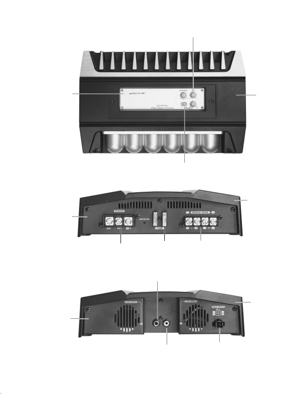
Location of main parts
Control panel
Volume knob
Heat sink
Switch knob
Rear panel
Front panel
Input for power
Fuse
Low input(R)
Heat sink
Output terminal
Heat sink
Low input(L)
High input connector
1-3
 Loading...