

Page 1
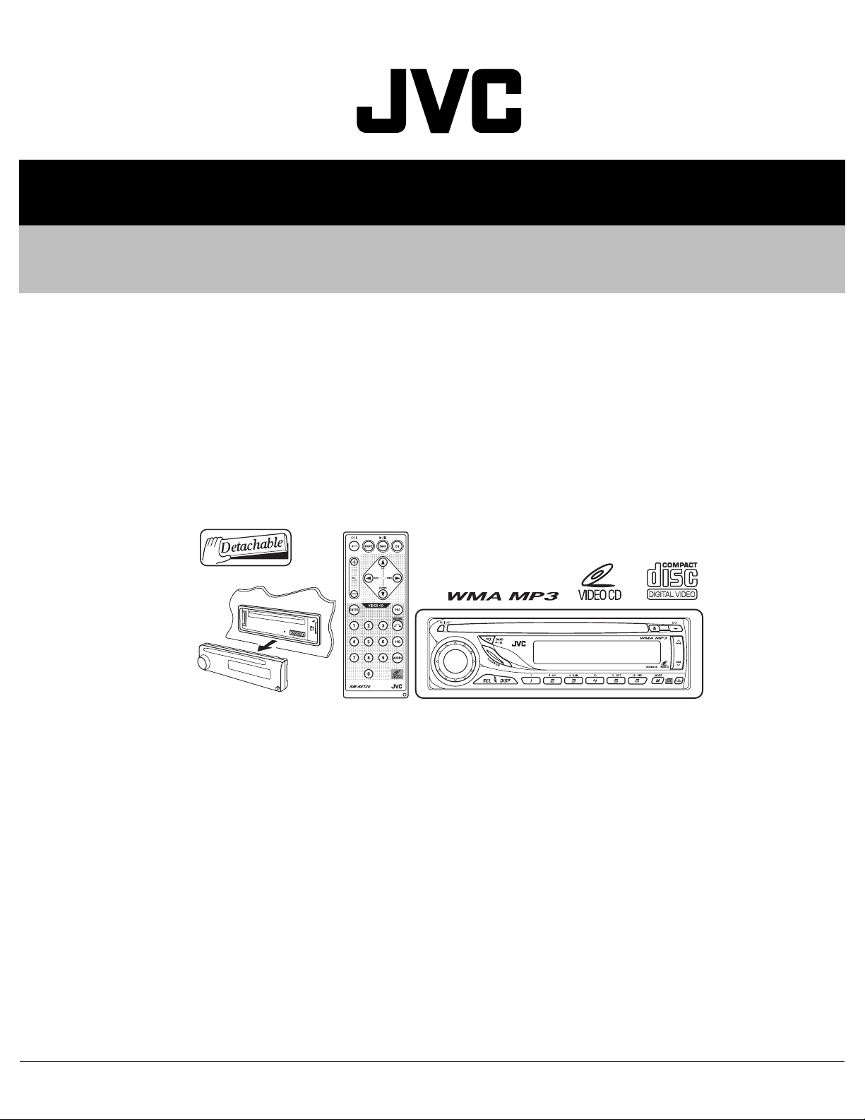
SERVICE MANUAL
VCD/CD RECEIVER
MA25620063
KD-SV3204UI,KD-SV3205U,
KD-SV3205UN,KD-SV3205UT,
KD-SV3205UH
Lead free solder used in the board (material : Sn-Ag-Cu, melting point : 219 Centigrade)
TABLE OF CONTENTS
1 PRECAUTIONS . . . . . . . . . . . . . . . . . . . . . . . . . . . . . . . . . . . . . . . . . . . . . . . . . . . . . . . . . . . . . . . . . . . . . . . 1-3
2 SPECIFIC SERVICE INSTRUCTIONS . . . . . . . . . . . . . . . . . . . . . . . . . . . . . . . . . . . . . . . . . . . . . . . . . . . . . . 1-6
3 DISASSEMBLY . . . . . . . . . . . . . . . . . . . . . . . . . . . . . . . . . . . . . . . . . . . . . . . . . . . . . . . . . . . . . . . . . . . . . . . 1-7
4 ADJUSTMENT . . . . . . . . . . . . . . . . . . . . . . . . . . . . . . . . . . . . . . . . . . . . . . . . . . . . . . . . . . . . . . . . . . . . . . . 1-11
5 TROUBLESHOOTING . . . . . . . . . . . . . . . . . . . . . . . . . . . . . . . . . . . . . . . . . . . . . . . . . . . . . . . . . . . . . . . . . 1-13
COPYRIGHT © 2006 Victor Company of Japan, Limited
No.MA256
2006/3
Page 2

SPECIFICATION
AUDIO AMPLIFIER SECTION
Maximum Power Output Front 50 W per channel
Rear 50 W per channel
Continuous Power Output
(RMS)
Load Impedance 4 Ω (4 Ω to 8 Ω allowance)
Tone Control Range Bass ±10 dB at 100 Hz
Frequency Response 40 Hz to 20 000 Hz
Signal-to-Noise Ratio 70 dB
Line-Out Level/Impedance 2.5 V/20 kΩ load (full scale)
Output Impedance 1 kΩ
Other Terminal LINE IN, CD changer
Color system PAL/NTSC
Video output (composite) 1 Vp-p/75 Ω
Frequency Range FM 87.5 MHz to 108.0 MHz
FM Tuner Usable Sensitivity 11.3 dBf (1.0 µV/75 Ω)
AM Tuner Sensitivity 20 µV
Type Compact disc player
Signal Detection System Non-contact optical pickup (semiconductor laser)
Number of Channels 2 channels (stereo)
Frequency Response 5 Hz to 20 000 Hz
Dynamic Range 96 dB
Signal-to-Noise Ratio 98 dB
Wow and Flutter Less than measurable limit
MP3 Decoding Format MPEG1/2 Audio Layer 3
WMA (Windows Media® Audio) Decoding Format Max. Bit Rate: 192 kbps
Power Requirement Operating Voltage:
Grounding System Negative ground
Allowable Operating Temperature 0°C to +40°C
Dimensions (W × H × D) Installation Size (approx.) 182 mm × 52 mm × 150 mm
Mass (approx.) 1.4 kg (excluding accessories)
Front 19 W per channel into 4 Ω, 40 Hz to 20 000 Hz at no more than
0.8% total harmonic distortion.
Rear 19 W per channel into 4 Ω, 40 Hz to 20 000 Hz at no more than
0.8% total harmonic distortion.
Treble ±10 dB at 10 kHz
VIDEO SECTION
TUNER SECTION
AM 531 kHz to 1 602 kHz
50 dB Quieting Sensitivity 16.3 dBf (1.8 µV/75 Ω)
Alternate Channel Selectivity (400 kHz) 65 dB
Frequency Response 40 Hz to 15 000 Hz
Stereo Separation 30 dB
Selectivity 35 dB
VCD/CD PLAYER SECTION
Max. Bit Rate: 320 kbps
GENERAL
Panel Size (approx.) 188 mm × 58 mm × 11 mm
Design and specifications are subject to change without notice.
1-2 (No.MA256)
Page 3
1.1 Safety Precautions
SECTION 1
PRECAUTIONS
!
!
Burrs formed during molding may be left over on some parts of the chassis. Therefore,
pay attention to such burrs in the case of preforming repair of this system.
Please use enough caution not to see the beam directly or touch it in case of an
adjustment or operation check.
(No.MA256)1-3
Page 4
1.2 Preventing static electricity
Electrostatic discharge (ESD), which occurs when static electricity stored in the body, fabric, etc. is discharged, can destroy the laser
diode in the traverse unit (optical pickup). Take care to prevent this when performing repairs.
1.2.1 Grounding to prevent damage by static electricity
Static electricity in the work area can destroy the optical pickup (laser diode) in devices such as laser products.
Be careful to use proper grounding in the area where repairs are being performed.
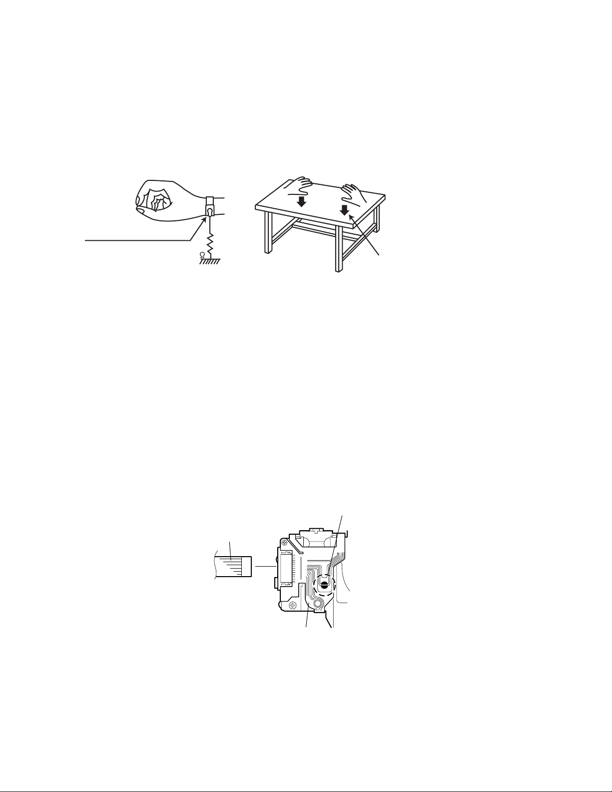
(1) Ground the workbench
Ground the workbench by laying conductive material (such as a conductive sheet) or an iron plate over it before placing the
traverse unit (optical pickup) on it.
(2) Ground yourself
Use an anti-static wrist strap to release any static electricity built up in your body.
(caption)
Anti-static wrist strap
1M
Conductive material
(conductive sheet) or iron plate
(3) Handling the optical pickup
• In order to maintain quality during transport and before installation, both sides of the laser diode on the replacement optical
pickup are shorted. After replacement, return the shorted parts to their original condition.
(Refer to the text.)
• Do not use a tester to check the condition of the laser diode in the optical pickup. The tester's internal power source can easily
destroy the laser diode.
1.3 Handling the traverse unit (optical pickup)
(1) Do not subject the traverse unit (optical pickup) to strong shocks, as it is a sensitive, complex unit.
(2) Cut off the shorted part of the flexible cable using nippers, etc. after replacing the optical pickup. For specific details, refer to the
replacement procedure in the text. Remove the anti-static pin when replacing the traverse unit. Be careful not to take too long a
time when attaching it to the connector.
(3) Handle the flexible cable carefully as it may break when subjected to strong force.
(4) It is not possible to adjust the semi-fixed resistor that adjusts the laser power. Do not turn it.
1.4 Attention when traverse unit is decomposed
*Please refer to "Disassembly method" in the text for the pickup unit.
• Apply solder to the short land before the flexible wire is disconnected from the connector on the pickup unit.
(If the flexible wire is disconnected without applying solder, the pickup may be destroyed by static electricity.)
• In the assembly, be sure to remove solder from the short land after connecting the flexible wire.
Short-circuit point
(Soldering)
Flexible wire
1-4 (No.MA256)
Pickup
Page 5
1.5 Important for laser products
!
1.CLASS 1 LASER PRODUCT
2.DANGER : Invisible laser radiation when open and inter
lock failed or defeated. Avoid direct exposure to beam.
3.CAUTION : There are no serviceable parts inside the
Laser Unit. Do not disassemble the Laser Unit. Replace
the complete Laser Unit if it malfunctions.
4.CAUTION : The CD,MD and DVD player uses invisible
laser radiation and is equipped with safety switches which
prevent emission of radiation when the drawer is open and
the safety interlocks have failed or are defeated. It is
dangerous to defeat the safety switches.
5.CAUTION : If safety switches malfunction, the laser is able
to function.
6.CAUTION : Use of controls, adjustments or performance of
procedures other than those specified here in may result in
hazardous radiation exposure.
Please use enough caution not to
see the beam directly or touch it
in case of an adjustment or operation
check.
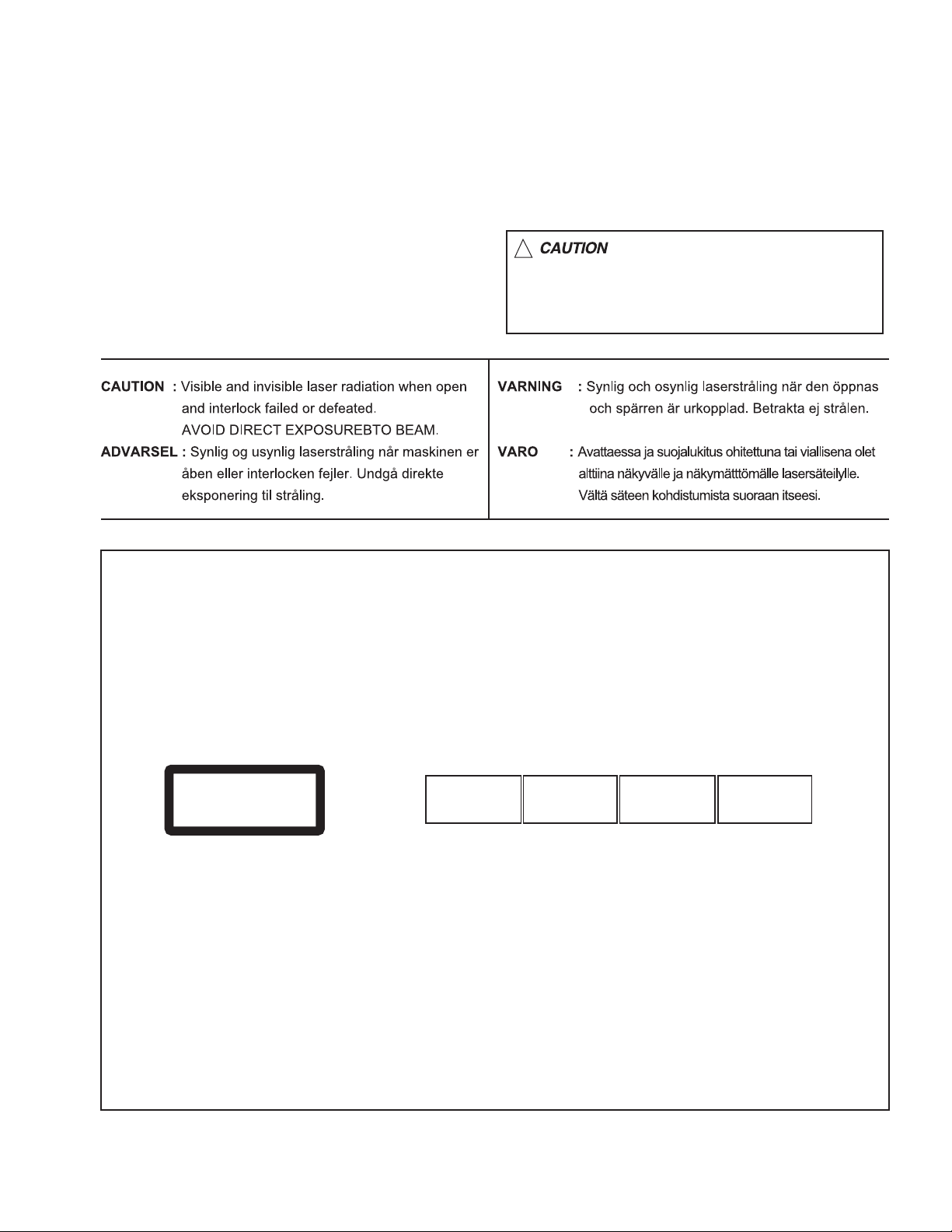
REPRODUCTION AND POSITION OF LABELS
WARNING LABEL
CAUTION : Visible and Invisible
CLASS 1
LASER PRODUCT
laser radiation when open and
interlock failed or defeated.
AVOID DIRECT EXPOSURE TO
BEAM. (e)
ADVARSEL : Synlig og usynlig
laserstråling når maskinen er
åben eller interlocken fejeler.
Undgå direkte eksponering til
stråling. (d)
VARNING : Synlig och
osynling laserstrålning när
den öppnas och spärren är
urkopplad. Betrakta ej
strålen. (s)
VARO : Avattaessa ja suojalukitus
ohitettuna tai viallisena olet alttiina
näkyvälle ja näkymättömälle
lasersäteilylle. Vältä säteen
kohdistumista suoraan itseesi. (f)
(No.MA256)1-5
Page 6

SECTION 2
SPECIFIC SERVICE INSTRUCTIONS
This service manual does not describe SPECIFIC SERVICE INSTRUCTIONS.
1-6 (No.MA256)
Page 7
SECTION 3
DISASSEMBLY
3.1 Main body section
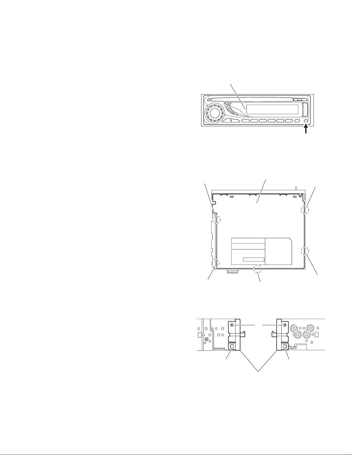
3.1.1 Removing the front panel assembly
(See Fig.1)
Push the detach button in the lower right part of the front panel
assembly and remove the front panel assembly.
3.1.2 Removing the bottom cover
(See Fig.2)
(1) Turn the main body up side down.
(2) Insert a screwdriver under the joints to release the two
joints a on the left side, tow joints b on the right side and
joint c on the back side of the main body, then remove the
bottom cover from the main body.
Note:
When releasing the joints using a screwdriver, do not damage
the main board.
Front panel assembly
a
Detach button
Fig.1
Bottom cover
b
3.1.3 Removing the front chassis assembly
(See Fig.3)
• Remove the front panel assembly and bottom cover.
(1) Remove the two screws A on the both sides of the main
body.
(2) Release the one joint d and one joint e on the both sides of
the main body, then remove the front chassis assembly toward the front.
a
c
Fig.2
b
A
d
Front chassis assembly
Fig.3
e
(No.MA256)1-7
Page 8
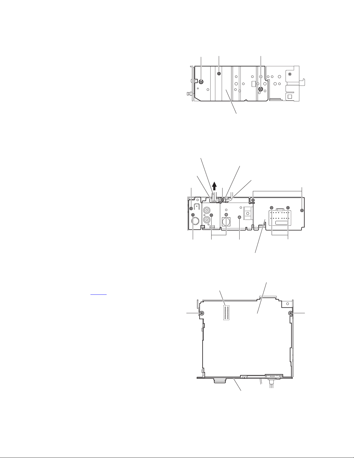
3.1.4 Removing the side panel
(See Fig.4)
Reference:
Remove the front panel assembly as required.
(1) Remove the one screw B and two screws C attaching the
side panel on the left side of the main body.
(2) Remove the side panel from the main body.
3.1.5 Removing the rear bracket
(See Fig.5)
• Remove the bottom cover.
(1) Remove the three screws D, one screw D', four screws E
and two screws F attaching the rear bracket on the back
side of the main body.
Reference:
When attaching the screw D', attach the wire holder of
the VIDEO OUT cable with it as before.
(2) Remove the LINE IN cable in the direction of the arrow from
the slot of the rear bracket.
(3) Remove the rear bracket.
C
LINE IN cable
Slot
B
Side panel
Wire holder
D'
C
Fig.4
VIDEO OUT cable
DD
3.1.6 Removing the main board
(See Fig.5 and 6)
• Remove the front panel assembly, bottom cover, front chassis
assembly and side panel.
(1) Remove the three screws D and one screw D' attaching the
rear bracket on the back side of the main body. (See Fig.5)
Reference:
When attaching the screw D', attach the wire holder of
the DVD OUT cable with it as before.
(2) Remove the two screws G attaching the main board. (See
Fig.6)
(3) Disconnect the connector CN301
the main body and take out the main board with the rear
bracket. (See Fig.6)
Reference:
Remove the rear bracket from the main body as required.
on the main board from
G
E
CN301
F
Rear bracket
Fig.5
Main board
EF
G
1-8 (No.MA256)
Rear bracket
Fig.6
Page 9
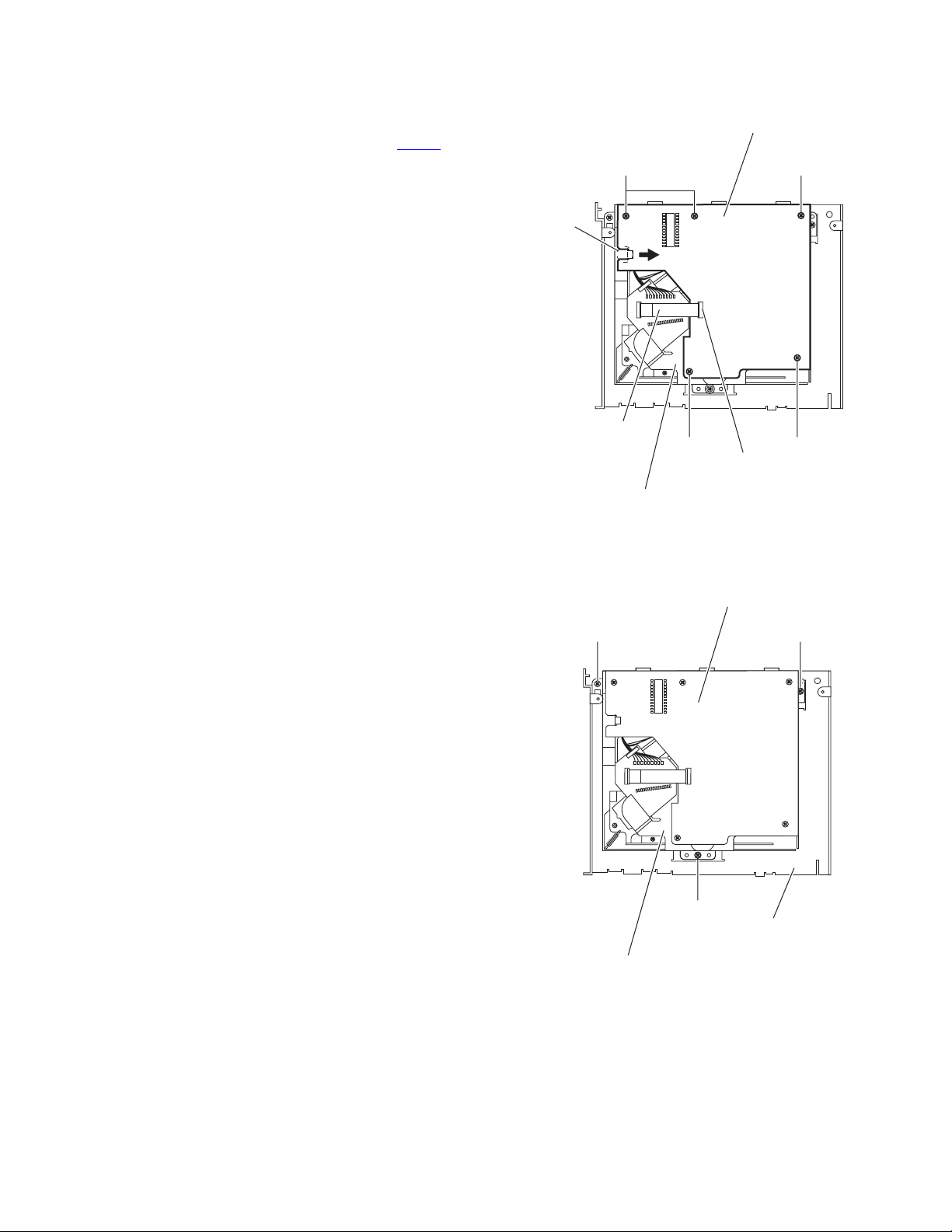
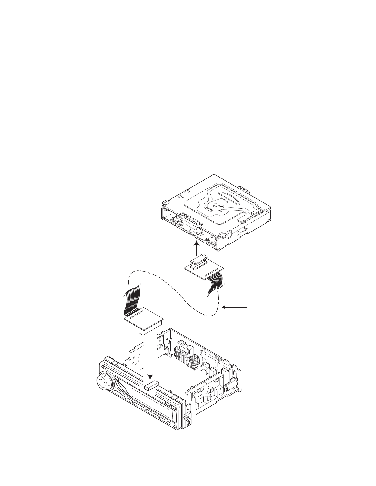
3.1.7 Removing the mechanism control board
(See Fig.7)
• Remove the front panel assembly, bottom cover, front chassis
assembly, side panel and main board.
(1) Disconnect the card wire from the connector CN601
mechanism control board.
(2) Remove the five screws H attaching the mechanism con-
trol board on the CD mechanism assembly.
(3) Remove the joint f in the direction of the arrow and take out
the mechanism control board from the CD mechanism assembly.
3.1.8 Removing the CD mechanism assembly
(See Fig.8)
• Remove the front panel assembly, bottom cover, front chassis
assembly, side panel and main board.
Reference:
Remove the mechanism control board as required.
(1) Remove the three screws J attaching the CD mechanism
assembly on the top chassis.
(2) Take out the CD mechanism assembly.
on the
Mechanism control board
H
f
Card wire
H
CD mechanism assembly
Mechanism control board
J
Fig.7
CN601
H
H
J
J
CD mechanism assembly
Fig.8
Top chassis
(No.MA256)1-9
Page 10
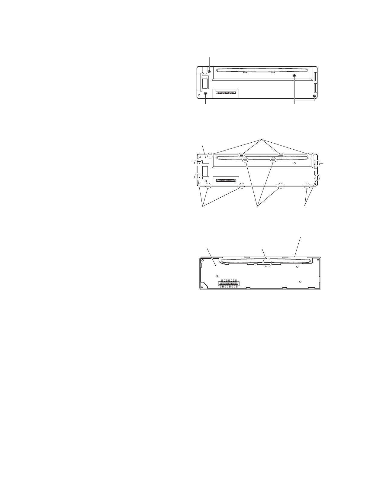
3.1.9 Removing the switch board
(See Fig.9 to 11)
• Remove the front panel assembly.
(1) Remove the four screws K on the back side of the front
panel assembly. (See Fig.9)
(2) Release the fourteen joints g and remove the rear cover.
(See Fig.10)
(3) Release the joint h and take out the switch board from the
front panel assembly. (See Fig.11)
K
K
Fig.9
g
Rear cover
g
g g
Switch board
g
Fig.10
Front panel assembly
h
K
g
3.2 CD mechanism section
For the CD mechanism section, please refer CD mechanism manual TN2001-1077 (No.MY001).
1-10 (No.MA256)
Fig.11
Page 11
SECTION 4
ADJUSTMENT
4.1 Adjustment method
Test instruments required for adjustment
(1) Digital oscilloscope (100MHz)
(2) Electric voltmeter
(3) Digital tester
(4) Tracking offset meter
(5) Test Disc JVC :CTS-1000
(6) Extension cable for check
EXTSH002-22P × 1
Standard volume position
Balance and Bass &Treble volume : lndication"0"
Loudness : OFF
How to connect the extension cable for adjusting
Caution:
Be sure to attach the heat sink and rear bracket onto the power amplifier IC and regulator IC respectively, before supply the power.
If voltage is applied without attaching these parts, the power amplifier IC and regulator IC will be destroyed by heat.
Standard measuring conditions
Power supply voltage DC14.4V(11 to 16V)
Load impedance 20KΩ(2 Speakers connection)
Output Level Line out 2.0V (Vol. MAX)
Dummy load
Exclusive dummy load should be used for AM,and FM. For FM
dummy load,there is a loss of 6dB between SSG output and
antenna input.The loss of 6dB need not be considered since
direct reading of figures are applied in this working standard.
EXTSH002-22P
(No.MA256)1-11
Page 12
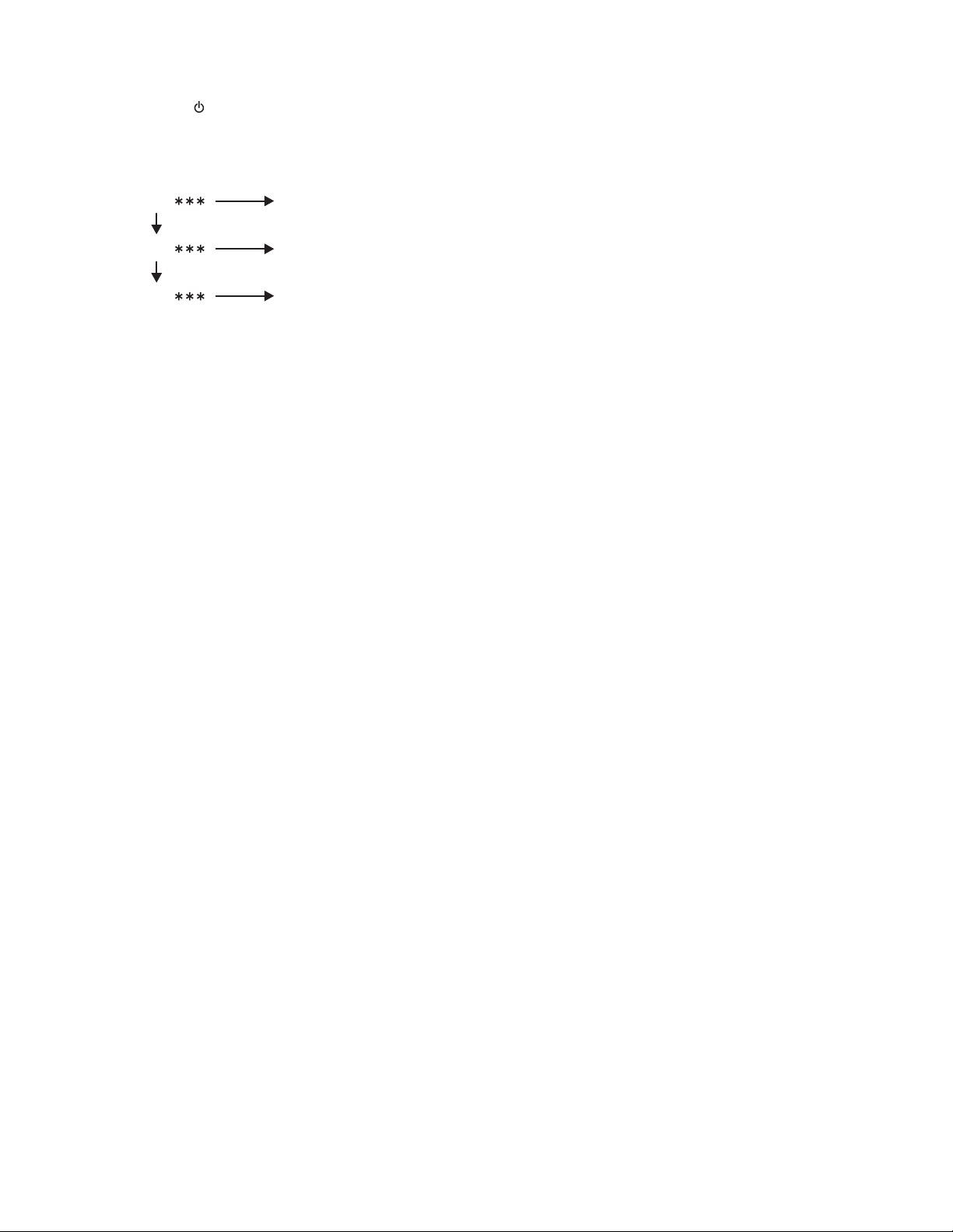
4.2 Confirmation method of a microcomputer version
1. Press the [ / I /ATT ] button.
2. Set this set at tuner mode.
3. Keep this state more than 2 seconds while continuing pressing the [BAND] button and [2] button sequentially.
4. It is displayed as follows by a display window.
MA Main micon version
CD CD micon version
CH CH micon version (It is displayed only in changer connection.)
Change each indication with the [SKIP] button.
1-12 (No.MA256)
Page 13

SECTION 5
TROUBLESHOOTING
5.1 Maintenance of laser pickup
(1) Cleaning the pick up lens
Before you replace the pick up, please try to clean the lens
with a alcohol soaked cotton swab.
(2) Life of the laser diode
When the life of the laser diode has expired, the following
symptoms will appear.
• The level of RF output (EFM output: amplitude of eye
pattern) will be low.
Is RF output
1.3 0.4Vp-p?
YES
O.K
(3) Semi-fixed resistor on the APC PC board
The semi-fixed resistor on the APC printed circuit board
which is attached to the pickup is used to adjust the laser
power.Since this adjustment should be performed to match
the characteristics of the whole optical block, do not touch
the semi-fixed resistor.
If the laser power is lower than the specified value, the laser diode is almost worn out, and the laser pickup should
be replaced. If the semi-fixed resistor is adjusted while the
pickup is functioning normally, the laser pickup may be
damaged due to excessive current.
NO
Replace it.
5.2 Replacement of laser pickup
5.2 Replacement of laser pickup
Turn off the power switch and,disconnect the
power cord from the ac outlet.
Replace the pickup with a normal one.(Refer
to "Pickup Removal" on the previous page)
Plug the power cord in,and turn the power on.
At this time,check that the laser emits for
about 3seconds and the objective lens moves
up and down.
Note: Do not observe the laser beam directly.
Play a disc.
Check the eye-pattern at RF test point.
Finish.
(No.MA256)1-13
Page 14

5.3 16 PIN CORD DIAGRAM
8
7
6
5
4
3
2
1
BK
RD
BL
BL/WH
WH
GN
VI
GY
14 YG
16 YL
8 BK
7 RD
5 BL/WH
YL
NC
YG
BR
WH/BK
GN/BK
VI/BK
GY/BK
16
15
14
13
12
11
10
9
PARKING
MEMORY
GND
ACC
REMOTE
BK
RD
BL
WH
BR
Black
Red
Blue
White
Brown
GN
VI
GY
YL
YG
GND
Green
Violet
Gray
Yellow
Yellow Green
PARKING
BRAKE
3 GN
11 GN/BK
2 VI
10 VI/BK
4 WH
12 WH/BK
1 GY
9 GY/BK
6 BL
13 BR
RR
FR
FL
Rear Right
Front Right
Front Left
RL+
RL-
RR+
RR-
FL+
FL-
FR+
FR-
ANT
TEL
REMOTE OUT
TEL MUTING
ANT
ACC
TEL
POWER ANTENNA
Auto Antenna
ACC Line
Telephone Muting
1-14 (No.MA256)
RL
REMOTE
Rear Left
Remote
GND
MEMORY
PARKING
Ground
Memory Backup Battery+
Parking Brake
Page 15

(No.MA256)1-15
Page 16

Victor Company of Japan, Limited
Mobile Entertainment Business Group Mobile Entertainment Category 10-1,1chome,Ohwatari-machi,Maebashi-city,Gumma-ken, 371-8543,Japan
(No.MA256)
Printed in Japan
VPT
Page 17

SCHEMATIC DIAGRAMS
VCD/CD RECEIVER
KD-SV3204UI,KD-SV3205U,
KD-SV3205UN,KD-SV3205UT
KD-SV3205UH
CD-ROM No.SML200603
Lead free solder used in the board (material : Sn-Ag-Cu, melting point : 219 Centigrade)
Contents
Block diagram
Standard schematic diagrams
Printed circuit boards
COPYRIGHT 2006 Victor Company of Japan, Limited.
2-1
2-2
2-5 to 6
No.MA256SCH
2006/3
Page 18

Safety precaution
!
!
Burrs formed during molding may be left over on some parts of the chassis. Therefore,
pay attention to such burrs in the case of preforming repair of this system.
Please use enough caution not to see the beam directly or touch it in case of an
adjustment or operation check.
Page 19

Block diagram
REST
LOAD/FEED
MOTOR
SPNDLE
MOTOR
PICK UP
&
FOCUS/
TRACKING
COIL
SW
SW1
SW2
CN001
REST
LOAD/FEED+
LOAD/FEED-
SPINDLE+
SPINDLE-
SW1,SW2
VA,VB,VE,VF
MD,LD
FOCUS+
FOCUSTRACKING+
TRACKING-
Video CD/CD servo control section
CN601
VA,VB
VE,VF
MD,LD
FOCUS+
FOCUSTRACKING+
TRACKINGSPINDLE+
SPINDLELOAD/FEED+
LOAD/FEED-
REST
SW1,SW2
IC601
CD RF
RFGC,RF
RFRP,FE
SEL,TEB
RFDC, TE
IC621
D.SERVO
& DSP
DMO
FMO
TRO
FOO
IC681
CD DRIVER
LOAD
LD/FE
IOP
RWSEL
IC200
DRAM
IC202
EEPROM
BUS0
BUS1
BUS2
BUS3
BUCK
CCE
DSPRST
IOP
RWSEL
AD0 to AD9
DB0 to DB15
WE#,RAS#
CAS
LD0 to LD7
LA0 to LA18
LWR#,LOE#
CS3#
CD-DATA
CD-LRCK
CD-BCK
HOST-DT
DSA-ACK
DSA-DATA
DSA-STB
ESS-ACK
HOST-STB
ESS-DT
ESSRST
CDON
IC571
DAC
IC201
VCD
DECODER
IC502
EEPROM
IC501
CPU
DATA
LRCK
MCLK
BCK
LD0 to LD7
LWR#,CS0#
SDA
SCL
AOTL+,AOTLAOTR+,AOTR-
VOUT
BUSSI
BUSSO
BUSIO
/BUSIO
BUSSCK
CD LPF
SDTI
CCLK
CSN
DACRST
IC203
DATA
LATCH
IC503
JBUS
BUFF
IC572
CD.LCH
CD.RCH
SUSSI/SO
BUSCLK
CDMUTE
CDREQ
B.DET
P. DE T
CDRESET
LINE IN
CABLE
CN501
ANT
Main amplifier section
CN302
CN301
Q701 to Q705
J1
LI.LI
LI.RI
SW
IC302
LINE IN
CDMUTE
CDREQ
B.DET
P.DET
CDRESET
/CDMUTE
/CDREQ
PS2
POWER
/CDRESET
AMP
TU1
FM/AM
TUNER PACK
VOUT
FM/AM
FM.OSC
IFCCONT
IFC,EO
AGC
S.METER
SD/ST
MONO
VIDEO
CD.LCH
CD.RCH
TU.LCH
TU.RCH
IC301
E.VOL
SDA
SCL
CH.L
CH.R
MICON.MUTE
IC550
DRIVER
Q341,Q351
Q361,Q371
LINE
MUTING
FLO,FRO
RLO,RRO
IC321
POWER
AMP
MUTE
Q321
MUTE
Q861
MUTING
ON3.3V,VDD,SW5V
CD8V,AUDIO9V,ILM10V
EACH
BLOCK
IC901,IC932
REGULATOR
ANTCTRL
LF+, LFLR+, LRRF+, RFRR+, RR-
ACC
REMOTE
ANT REMOTE
TEL MUTING
Q904
Q905
CJ702
VIDEO OUT
CABLE
CJ341
FRONT/REAR
LINE OUT
CN901
SPEAKER
BATTERY
CORD
LCD and key control section
S1 to S52
LCD1
LCD MODULE
COM1 to COM3
D630 to D649
D652,D653
LIGHTING
DISPLAY
IC661
LCD
DRIVER
LCD.SCK
LCD.SO
LCD.CE
Q670,Q671
DIMMER
CONT.
DIMOUT
JS686
ENCODER
ENC1
ENC2
S601 to S616
KEY0 to KEY2
KEY
MATRIX
IC681
REMOCON
RECEIVER
REMOCON
CJ601
LCD.SCK
LCD.SO
LCD.CE
KEY0 to KEY2
DIMOUT
REMOCON
CN701
ENC1
ENC2
IC701
u-COM
RESET
S701
RESET
SW
SI
BUSCLK
SI, SO, I/O,INT, SCK
IC801
JVC BUS
PARKING BRAKE
SI/SO
CH.SCK
TELMUTE
MUTECONT
PARKING BRAKE
Q963
EXT
J801
CHANGER
2-1
Page 20

Standard schematic diagrams
Main section
J1
QNB0190-001
1.5k
QGB2027M4-22S
CN301
CN701
QGZ1601J1-15
CDREQ
CDMUTE
CJ702
QGA2501F1-02
C384
0.047
R774
C772
R773
2.2/50
C773
0.001
Q772
2SC3928A/QR/-X
C5004
1.5
120
1k
R5501
R5503
P.DET
B.DET
CDRESET
Q703
RT1N141C-X
C719
0.1
C716
C717
D701
C718
0.47
0.47
0.47
UDZW6.2B-X
Q702
Q701 Q704 Q705
RT1N141C-X
RT1N141C-X
C728 C729C730
0.01 0.010.01
D703
D705
D702
D706
D704
D707
UDZW6.2B-X
UDZW6.2B-X
UDZW6.2B-X
UDZW6.2B-X
UDZW6.2B-X
1k
K5308
NQR0007-002X
QQR0797-002
IC550
MM1510XN-X
C5001
220/10
C5002
0.047
D709
D708
UDZW6.2B-X
UDZW6.2B-X
R772
10k
Q771
2SC3928A/QR/-X
LF501
UDZW6.8B-X
R733 R734
47k 47k
RT1N141C-X
UDZW6.2B-X
D710
QSW1049-001Z
UDZW6.2B-X
UDZW6.2B-X
C5305
68p
D5301
R5505
C5003
220/10
RT1N141C-X
UDZW6.2B-X
D711
S701
D750
C771
75
D771
220/10
L5501
4.7
BUSCLK
/CDMUTE
/CDREQ
POWER
/CDRESET
CD.RCH
CD.LCH
DETACH
REMOCON
ENC1
ENC2
DIMOUT
LCD.SCK
LCD.SO
LCD.CE
R750
39
R771
0
UDZW10B-X
R5504
1k
R5502
10
SI
PS2
KEY0
KEY1
KEY2
0.1
C731
0.047
C737
CH.R
CH.L
VIDEO
TU1
QAU0312-001
MC2838-X
UDZS4.7B-X
470
D861
R861
CH.R
A.GND
CD.RCH
C301
2SC3928A/QR/-X
Q902
R910
47k
R914R913
1k47k
D914
MC2836-X
Q905
RT1N141C-X
Q861
RT1P141C-X
220/6.3
D866
C861
C862
CD.LCH
QTE1H55-225Z
C401
QTE1H55-225Z
C314
R909
27k
2SA1530A/QR/-X
220/10
C911
0.1
C919
MUTE
MC2836-X
0.082
MICON.MUTE
C410
2.2/50
C312
QTE1C56-476Z
0.22
Q903
IC932
BA33BC0FP-X
0.1
C933
FRO
FLO
MUTE
RRO
RLO
CH.L
C311
C411
QTE1A56-107Z
2.2/50
0.1
C313
R907
39k
R908
68k
0.47
C934
100/10
L1
4.7
R2
1k
1k
R3
47
C802
EO
C554
2.2
C552
470p
LEVEL
S.METER
C721
0.1
C722
0.1
C723
22p
X701
QAX0406-001Z
C724
22p
IFCCONT
IFC
FM.OSC
EO
VIDEO
C720
0.01
REMOCON
0.01
0
R1
Q3
2SA1530A/QR/-X
MC2838-X
MM1565AF-X
IC701
UPD178078GF-723
R715
R716
J801
QNZ0095-001
1SS355W-X
D1
D5
IC551
X1
10k
47k
VPP
RESET
1SS355W-X
D2
R5
47k
0.01
C3
R6
3.3k
C553
47/10
C4
2SA1365/F/-X
1
0.47/50
C1
4.7k
R717
0.022
C2
Q1
R8
4.7k
Q2
RT1N141C-X
/CDREQ
/CDMUTE
220/10
0.1/50
0.047
220/10
R4
0.012
47/10
C13
R7
47k
FM/AM
R712
4.7k
R713
4.7k
R714
4.7k
/CDRESET
R802
47K
C6
12
R9
KEY2
22k
R711
0.012
C84
C94
C8
C5
C7
0.01
C14
C12
0.01
120p
10k
C10
R11
12
R10
Q4
RT1N141C-X
IFC
FM.OSC
IFCCONT
KEY0
KEY1
ENC2
ENC1
DIMOUT
22k
22k
1k1k47k
R710
R709
R737
R738
R736
47k
R718
R806
R805
100k 1k
R804
22k
R803
100
HD74HC126FP-X
47k
R739
C83
10k
R12
AGC
IC801
C93
27k
10k
R13
R14
1SS355W-X
D3
100K
LCD.CE
3.3k
R706
10k
R15
S.METER
LCD.SCK
3.3k
R705
RXDO
FM/AM
QTE1H56-105Z
C81
R201
R101
C91
QTE1H56-105Z
R16
330p
C11
SD/ST
SCL
LCD.SO
270
3.3k
R703
R704
R740
TXDO
SD/ST
0
SDA
270
R702
47k
MONO
R810
100
C801
0.047
AGC
SI
R808
1.8k
1.8k
Q5
RT1N141C-X
MONO
0
R728
330
10k
R92
S0
R809
22k
R801
47k
10k
R82
TU.LCH
I/O
4.7k
R729
0.0068
C92
TU.RCH
SO
SCK
4.7k
R730
LEVEL
4.7k
R731
R807
100K
0.0068
C82
SI
0
R732
QTE1H56-105Z
C101
R247
56k
INT
R725
R724
R723
R726
R722
R721
R720
R719
SCK
C803
QTE1H56-105Z
0.1/50
C9
C201
C244
D242
0.22/50
2.2k
1k
1K
1.2k
1.2k
47k
47k
47k
C243D243
0.0471SS355W-X
R246
1SS355W-X
R811
R244
12k
Q241
R245
100
2SC3928A/R/-X
C242
1k
R735
R701
R707
100k
R708
R727
R249
180k
R242
22k
22/16
4.7k
4.7k
VDDVSS
C727
220p
DETACH
1k
POWER
MUTECONT
1k
TELMUTE
C726
0.01
C725
220/10
C732
220/10
ANTCTRL
BUSCLKA.GND
D867
470
R862
C241
1/50
D251
D241
1SS355W-X
TU.LCH
L701
R251
220k
TU.RCHMICON.MUTE
4.7
MUTECONT
RT1N141C-X
Q904
1SS355W-X
R241
220k
C918
0.1
R248
47k
PS2
SI
SO
TELMUTE
I/O
INT
SCK
C412C413
1SS355W-X
1SS355W-X
1SS355W-X
1SS355W-X
2.2/502.2/50
C402 C302
RT1N141C-X
C931
D341
D351
D361
D371
R301
22k
0.0082 0.0082
R401
22k
R966
47k
Q963
D903
1SS355W-X
D931
1A3G-T1
D932
1A3G-T1
R342
1k
R352
1k
R341
2.2k
R351
2.2k
KTD1304-X
KTD1304-X
R361
2.2k
R371
2.2k
R362
1k
R372
1k
R302
2.2k
C303
0.22
C304
0.22
C404
0.22
C403
0.22
TEA6320T-X
R402
2.2k
R975
4.7k
10k
R967
C370
10/16
R905
100K
100/10
R904
C932
R377
R379
C379
IC301
1SS355W-X
4.7k
Q351
Q361
47/16
R381
10k
47k
R303
C307
QTE1E56-475Z
47k
R403
22/16
4.7k
C905
R903
KTD1304-X
Q371
KTD1304-X
R385
10k 10k
47k
R304
C308
QTE1E56-475Z
QTE1E56-475Z
C309
C408
C407
QTE1A56-107Z
QTE1E56-475Z
47k
R404
C915
2.2/50
0.1
22/16
9.1k
C904
R901
C906
R386
R387
R382
R383
SDA
C310
R2S25400DS-E
22/16
C903
Q341
R374
10k
10k10k
R378
10k 10k
R380
0.022
47/6.3
C377
C375
C376
47/6.3
R388
10k
C305
0.033
C306
C405
0.0056 0.0056
0.033
C406
D906
0.01
100/10
100/10
0.01
C907
C909
C910
C908
R343
100
R307
1k
R308
1k
R408
1k
R407
1k
0.1
C914
R911
C902
0.01
C901
3300/16
QQR0703-001
D901
L901
C382
100p
C319
100p
C320
C420C419
100p100p
2.2k
1N5401-F64
0.01
C912
0.1
C341
0.082
C361 CJ341
0.047
C378
180p
R384
470
C381
0.047
D992
CRS03-W
C964
100p
C963
100p
C962
100p
C961
100p
C966
100p
C965
100p
C968
100p
C967
100p
D995
CRS03-W
RR+
MUTE
2.2k
R950
RF+
RR+
LR+
LF+
RF-
RR-
LR-
LF-
C917
10/16
10k
10k
10k
FLO
0.01
D904
CRS03-W
IC302
RLO
IC901
C371
22/6.3
C372
10/16
R375R376
NJM4565V-X
C373
10/16
C374
22/6.3
FRO
SCL
D905
CRS03-W
R902
C916
2.2/50
R353
100
R363
100
R373
100
LI.RI
100k100k
LI.G
LI.LI
RRO
C334
0.47
C335
0.47
C435
0.47
C434
0.47
Parts are safety assurance parts.
When replacing those parts make
QNN0773-001
CN302
QGA2006C1-04
IC321
LR-
LF+
LF-
LR+
C331
0.022
QTE1C57-107Z
C332
C439
4700p
C333
C438
4700p
C433
4700p
C437
C432
C436
4700p
RF+
RR-
RF-
R323
1k
D908
CRS03-W
R912
10k
C329
QNZ0611-001
D907
C427
2.2/50
QTE1C56-226Z
4.7/25
1000P
D321
1SS355W-X
CN901
CRS03-W
C321
C328
0.022
C330
C338
TB2904HQ
1k
R322
R321
47k
R325
0
Q321
RT1N141C-X
4.7/50
C327
sure to use the specified one.
2-2
Page 21

CD section
0.01
C612
QGF0501F8-22X
CN601
VA
VF
VE
VREF
VB
R615
MD
150
FOCUS+
FOCUSTRACKING+
TRACKINGSPINDLESPINDLE+
REST
SW2
SW1
LOAD/FEED-
LOAD/FEED+
0.01
C613
DB9
DB5
DB3
DB7
DB15
DB13
0.1
C201
100k
L200
47u
VGND
Q200
RT1N141C-X
TMP91CY22FG6H96
R229
DB14
IC501
DB11
DB12
DB10
DB8
DB6
DB4
DB2
R242
R241
R240
C203
0.1
0.1
0.1
510
R232
C213
C215
C224
C501
0.0033
1k
R501
CDON
1k
R502
CDREQ
1k
100
R503
R306
ESSRST
CDMUTE
47/16
47k
R304
ESS-DT
0
RFRP
0.1
SEL
2SA1947/E/-X
Q601
TRO
47/6.3
R631
47/6.3
C685
C686
R690
33k
R689
12k
R685
6.8k
R687
6.8k
56k
R609
TEB
C604
0.01
FOO
100
R630
FOCUS+
FOCUSTRACKING+
TRACKING-
C637
C636
C632
C631
100
R686
R688
R607
R634
R633
R632
1.8k
FE
C606
47/6.3
82k
R608
820
0.047
0.047
470p
470p
0
0
0
C623
R624
5.6k
47/6.3
TRO
12k
FOO
VREF
DMO
C690
10/6.3
C682
4.7/35
C683
0.1
C684
47/16
C607
RWSEL
RFDC
TE
C605
0.0068
0.047
C635
C630
R629
10k
C627
R628
R626
47p
R625
C628
0
B681
1SR154-400-X
D682
47/16
C693
47/16
C694
CDON
0.01
0.047
C634
0.033
C629
0.01
C625
C616
10/6.3
0.047
C633
SEL
TEB
RFGC
TE
RFDC
FE
RFRP
0.033
RF
C626
0.0027
0.01
1.5M
C624
470k
R627
47k
C514
C508
0.01
IOP
IC502
BR24L01AFV-W-X
0.015
15k
IC200
IC41LV16100S50T
ESSRST
HOST-DT
DACRST
CSN
CCLK
SDTI
DSA-ACK
DSA-DATA
DSA-STB
VOUT
CDON
Q501
RT1P141C-X
R539
47k
R542
R543
R544
R545
C509
0.01
R549
4.7k
4.7k
R550
8.2k
R548
R525
100k
NAD0028-103X
0.01
C510
TH501
D200
1SS374-X
L202
2.2u
470p
C222
R227
L201
P.DET
R516
R540
47k
10k
330
330
10k
R200
R243
R201
R244
R233
R213
R214
R215
R202
R203
R245
R246
R247
C208
R234
R235
R204
R236
R248
470p
C223
0
47u
RT1P141C-X
1k
BOOT
Q201
0.1
75
R230
8VDET
BUSSCK
R210
0.01
C219
75
R231
10k
10k
1k
10k
10k
1k
1k
10k
1k
47/6.3
C200
C211
0.1
RF
R610R611R612R614
10010k2k15k
C609
22
R605
R606
27p
NAX0375-001X
0.01
R623
C621
CD-DATA
C603
0.1
22
RFGC
100/6.3
FMO
DMO
C638
100
100
R635
R636
L621
2SB1184/QR/-X
Q681
C608
C639
0.01
47u
C622
R613
68p
C611
1k
C610
5p
IC601
TA2157FN-X
82k
4.7k
R641
0.01
C646
R682
R681
6.8k
R683
6.8k
R601
82k
R602
330k
R603
330k
R604
0.01
C601
C602
R616
47/6.3
10k
27p
C100
C101
0.01
47/6.3
100p
X571
L622
47u
C643
0.01
10k
R642
47/6.3
0.33
C644
C645
R252
R253
FMO
2.2K
3.9k
R684
15k
R691
0
B682
LOAD
LD/FE
10K
C687
C688
C642
IC621
TC94A14FA
10K
10K
R254
C641
C640
R100
R621
CD-BCK
0
1M
R637
474747
R622
CD-LRCK
IC681
BA5830FP-X
VB
VA
VF
VE
MD
IOP
LD
C614
NI
BUS0
BUS1
BUS2
BUS3
BUCK
CCE
DSPRST
4.7k
4.7k
4.7k
R638
R639
R640
L623
47u
SPINDLE+
SPINDLELOAD/FEED+
LOAD/FEED-
CN502
QGF0501F1-08X
RESET
BUSSCK
BOOT
BUSSI
BUSSO
DB1
DB0
C204
C216
47k
R303
HOST-STB
DB15
0.1
0.1
SW2
DB13
DB14
1k1k1k
R237
R238
ESS-ACK
C507
47k
R507
REST
RAS#
WE#
DB12
R239
HOST-STB
0.0027
47k
R506
ESS-ACK
AD9
DB11
R249
ESS-DT
47k
R302
AD8
DB9
DB10
10k
R250
R205
BUSIO
HOST-DT
AD7
AD0
/BUSIO
100
R534
47k
R301
AD6
AD5
AD4
0.1
C202
AD2
AD3
AD1
DB8
DB7
DB6
DB5
DB4
DB3
DB2
DB1
DB0
AD8
AD7
AD6
AD5
AD4
0.1
C214
CS0#
CS3#
LD0
LD1
LD2
LD3
LD4
LD5
LD6
LD7
47k
R524
R526
R523
R522
R521
R520
R519
R518
R517
R513
1k
C503
270p
100/6.3
LOAD
100
R533
LWR#
LD/FE
1k
R532
LOE#
RWSEL
47k
R531
BUSSO
47k
R530
BUSSI
47k
R528
R529
BUSSCK
R527
C502
AD3
AD2
R307
R308
R309
R509
R512
R511
NAX0385-001X
R510
100
C504
R508
AD1
R515
R514
LA17
LA16
AD0
LA0
100
100
100
100
100
100
100
47k
47k
X501
22P
47k
LA15
LA14
AD9
WE#
LA1
LA2
DSPRST
CCE
BUCK
BUS0
BUS1
BUS2
BUS3
DSA-DATA
DSA-ACK
DSA-STB
47k
47k
47k
47k
47k
1k
CDRESET
C505
C506
LA0
SW1
B.DET
LA13
RAS#
LA3
LD7
LA12
IC201
ES3890FF
LA4
22P
0.01
RESET
LD6
LD5
LD4
LD3
LD2
47k
LA9
LA11
LWR#
LA10
0.1
C205
680
R211
R219
100k
LA5
CDON
CDON
R206
R207
4.7k
R223
R220
0.1
NAX0550-001X
X200
L501
47u
C512
100/6.3
C513
0.01
C511
BUSSO
6.8k 3.9k
C551
BUSSI
BUSIO
/BUSIO
BUSSCK
LA18
LA19
SA16M90TFIR1CV3
0
R212
C207
0.1
4.7k
4.7k
R222
R221
CD-BCK
CD-DATA
CD-LRCK
LA19
LA18
LA17
LA16
LA15
LA14
LA13
LA12
LA11
LA10
LA9
LA8
C210
LA7
LA6
C689
100/6.3
C220
18p
15p
C221
0.1
R561
R568
R563
0.01
IC503
R569
1k
R570
1k
R553
18k
33k
R554
LD0
LD1
LOE#
LA8
LA7
LA6
LA5
LA4
IC202
4.7k
R209
R218
R224
R251
IC303
NJM2885DL1-26-W
100/6.3
C405
NJU7241F33-X
IC504
100k
1k
R562
SN74AHCT126PW-X
100k
R551
CS3#
LA3
LA1
IC204
SN74AHC1G32DC-X
C209
LA2
0.1
47/6.3
C218
C212
0.1
IC203
SN74LV273APW-X
DACRST
CSN
CCLK
SDTI
C481
100/6.3NI0.01
R560
100
R555
0.1
MCLK
DATA
LRCK
C401
BCK
100
IC571
AK4385ET-X
330p
R584
C584
12k
R586
43k
Q304
2SB1184/QR/-X
R300
47k
470
R305
Q302
RT1N141C-X
0
R559
47u
L502
CRS03-W
R556
0
100k
R558
R597
12k
D506
B501
47
47
47
47
C404
C402
0.01
100k
R552
C582
120p
4.7/35
CD.R-CH
8VDET
Q502
0
R557
120p
C588
C590
C594
RT1N141C-X
100k
R599
43k
C406
100/6.3
0.01
LD0
47k
R582
IC572
NJM4580V-X
R588
R592
R590
C596
C599
0.01
LD1
0.1
C573
R595
47/6.3
C595
R225
000
LD2
47k
R226
LD3
47/6.3
C574
12k
C593
0.01
R228
LD4
LD5
L572
47u
C597
47K
12k
4.7
R593
C217
R208
0
LD6
LD7
RT1P141C-X
R481
39
D481
UDZW5.1B-X
1000p
1000p
C598
C581
120p
120p
C587
43k
R585
47K
R587
47/6.347/6.3
C591C592
12K
R591
12K
R589
CD.L-CH
CD.L-CH
CD.R-CH
9V
ON3.3V
CDMUTE
CDREQ
CDRESET
B.DET
P.DET
BUSSI/SO
BUSCLK
CD5V
CD8V
CN501
QGB2027LA-22X
R596
LWR#
12k
12k
R583
CSN
CCLK
SDTI
DACRST
CS0#
Q571
Q572
RT1N141C-X
R594
47k
43k
4.7/35
R598
C589
CDON
R581
47k
330p
C583
2-3
Page 22

LCD & Keey control section
S601
IC681
RPM7338-V4
C682
D681
0.012
UDZW6.2B-X
C681
R682
LCD1
QLD0387-001
R602R603R604
R605
2.7k
S602
R609
R610
2.7k
R608
1.8k
1.2k
S611S612
S610
R613
1.2k
S616
8201.2k1.8k
R612
R607
820
820
R601
KEY2
820
S606
S605S604S603
R606
KEY1
820
S607
S608S609
R611
KEY0
820
S613S614S615
R630
820
D630
S4
S3
S5
S1
D631
D635
470
R631
R632
B635
0
B634
0
R635
S13
S12
S11
S10S9S8S7S6
D632
D633
B633
0
D634
R636
S19
S18
S17
S16
S15
S14
B636
0
D644
470
R633
R634
S25
S24
S23
S22
S21
S20
D640
D636
D637
330
R637
S26
R638
S31
S30
S29
S28
S27
330
R639
S32
D641
D638
D639
S37
S36
S35
S34
S33
330
R640
R641
S43
S42S2S41
S40
S39
S38
D645
D643
D642
470
R642
R643
S49
S48
S47
S46
S45
S44
D647
D646
R644
COM1
S52
S51
S50
COM2
COM3
S51
S52
R661
2.2K
470
R645
D649
D648
R646
D652
NSPW310BS/BRST/
560
R650
R649
Q670
D653
NSPW310BS/BRST/
2SA1365/F/-X
560
Q671
R670
470
1K
R672
RT1N141C-X
R671
R662
2.2K
R664
10K
47K
180K
D661
1SS355W-X
R663
C662
680p
C661
10/6.3
DIMOUT
IC661
PT6523LQ-L
D662
UDZW5.1B-X
R665
51K
LCD.CE
LCD.SCK
LCD.SO
C663
0.022
R666
R667
R668
COM1
COM2
COM3
10K
10K
10K
4.7/6.3
10K
R681
470
S44
S45
S46
S47
S48
S49
S50
INH
OSC
CE
CLK
DATA
S3S4S5S6S7S8S9
S2
R687
47K
R688
47K
C686
0.022
S35
S36
S37
S40
S41
S42
S43
S38
S39
S10
S11S1S12
S13
JS686
QSW0976-001
100
R686
C687
0.022
C664
0.1
S33
S34
S32
S31
S30
S29
S28
S27
S26
S25
S24
S23
S22
S21
S20
S19
S18
S17
S14
S15
S16
QGZ1601K1-15S
CJ601
10V
REMOCON
ENC1
ENC2
DIMOUT
LCD.SCK
LCD.SO
LCD.CE
KEY0
KEY1
KEY2
2-4
Page 23

Printed circuit boards
Main board
C901
B351
B352
IC321
C321
C5003
L5501
C5001
Lead free solder used in the board (material : Sn-Ag-Cu, melting point : 219 Centigrade)
Forward side Reverse side
IC901
C915
L901
CN901
B353
C964
C963
C962
D992
CJ702
IC550
IC551
C934
C5004
C965
C961
C328
LF501
C968
D995
C967
C966
C427
C370
D901
C327
C916
C338
C334
C335
C434
C861
D932
C435
C408
PP1
C309
C308
C732
CN301
D931
C917
R902
C911
R322
R321
Q321
D321
R325
C311
C407
C307
L701
IC801
C803
R801
R809
R810
C412
C725
R730
R806
R732
C907
C910
R905
C906
R904
C905
C909
C904
PP2
C312
C313
C314
R811
R804
R728
C401
IC301
C410
C301
R740
R807
R808
R729
S701
C903
C908
C377
IC302
C413
C411
R739
C242
C241
IC701
R750
R737
R736
R738
CJ341
C374
X701
D351
R16
R351
C373
D711
Q351
D341
C371 C372
C771
C14
C101
C201
D710
J801
PP3
C375
C379
C244
D904
J1
Q341
Q361
Q371
CN302
R341
D371
D361
R361
R371
TU1
L1
C13
C772
C4
C8
C91
C81
CN701
C1
C5
C9
J1
CJ341
C361
R362
R363
R372
C381
C6
C2
C3
C1
C7
C5
R4
C83
C84
C94
C93
C9
Q4
R11
Q5
R373
CN302
B360
TU1
C372
C373
L1
D1
D2
C13
R3
R773
C773
Q772
Q771
C4
R774
R6
D5
C8
R2
R101
C91
C81
C11
D3
C717
C718
D701
R352
R353
R343
R342
R375
R387
R376
R382
C771
R772
D771
R771
C772
Q1
R1
R92
C12
C14
C92
C101
R82
C201
C82
R201
R13
R12
C10
R14
R717
C716
CN701
J801
C341
C802
C371
R386
C374
R380
R383
R384
C378
Q2
R379
R388
R8
R7
R5
R9
Q3
R10
R246
R247
Q241
R248
R245
D243
R15
X701
C723
C731
R712
R704
R706
R705
C903
C908
R374
R385
R378
C375
C379
R377
R244
C242
R709
R249
C244
C241
R726
RESET
VPP
X1
C724
R715
C726
C720
C721
R713
R711
R710
R714
R703
R735
IC901
C909
C904
C377
C413
C376
C401
R381
C411
C404 C405
C243
R242
D242
C410
D251
D241
C301
R5501
R241
RXDO
TXDO
R716
R718
R721
R720
R723
C722
R702
R701
C384
D750
S701
C915
R911
D905
L701
Q902
C725
R401R402
C402
D903
R902
R910
C310
C304 C305
R302
R727
R708
R707
R802
R950
L901
C436
D901
C916
R308
C407
R403
R304
R303
C306
C307
SI
R733
R734
Q705
C728
R731
R803
Q704
Q702
C919
C327
C338
R323
R307
C334C335
R408
C434
C435
R407
D861
R861
C408
D866
R862
C862
R404
C309
R966
R967
R975
D906
C308
R914
R913
C732
C386
C738
C719
Q701
Q703
C730
CN301
C729
D931
D932
D908
D907
R912
C917
C905
C911
R901
R903
R908
R907
R909
Q903
C312
C311
C406
C403
R251
C303
C412
C302
R301
R719
GND
R722
R724
R725
VDD
C727
S0
SCK
R805
C801
D707
D706
D704
D708
D703
D705
D709
D702
CN901
C437
C438
C439
C914
C427
C328
Q861
C383
D867
C861
C370
Q963
Q904
Q905
CJ702
LF501
C382
R5504
C5305
D5301
R5503
C5004
IC932
C933
D914
C918
C901
C902
C912
C330
C332
C333
C319
C320
C433
C419
C329
C420
C432
C321
IC321
C331
K5308
R5505
C5003
C5002
L5501
C5001
C553
C931
C934
C737
R5502
C554
C552
Switch board
D630
S613
D635
JS686
R634
R633
R611
B636
B633
B634
D631
S612
Lead free solder used in the board (material : Sn-Ag-Cu, melting point : 219 Centigrade)
Forward side Reverse side
D644
D
6
3
4
R635
R636
D
6
3
B635
R637
D637
R638
R610
IC681
S614
D
3
6
3
2
D652D653
S
6
0
1
R604
R605
D636
LCD1
S602
D640
S611
R639
R609
R640
D638D639
R607
R608
S609S610
D641 D642
S608
R606
R641
S603 S604
R642
R602
D643
R603
D649
D645
S607
D648
S606
S615
D646
R613
D647
S616
S605
R612
R601
C664
R643
R644
R645
R646
CJ601
IC661
C663
C662
R665
R667
R666
R668
D652D653
R649
R650
C661
R663
D661
R664
681
IC
R630
JS686
R631
D681
D662
R670
R661
R662
R682
C681
C682
R681
Q670
R688
Q671
R672
C687
R671
R686
R632
R687
C686
2-5
Page 24

CD mechanism control board
Forward side Reverse side
Lead free solder used in the board (material : Sn-Ag-Cu, melting point : 219 Centigrade)
R682
R684
C683
R683
R691
R681
B682
R638
R520
D682
C694
C693
R639
R519
C682
R640
R518
R641
R642
R517
C687C688
C691
C644
R521
R522
Q681
C690
R523
C684
R630
R631
C101
X571
IC681
C630
R634
C638
R635
R637
C685 C686
R685
R690
C605
R633
L621
R608
R632
C603
C636
C692
C100
R686R687
C606
R689
R100
L622
L623
R688
C637
C635
C631
C622
R605
R606
C634
C632
R636
C640
C642
C641
Q601
C633
C616
R629
C629
IC621
R616
C639
R532
C607
R607
C646
R525
R533R534
CN601
C643
R626
C623
C645
R625
C621
IC601
R609
C627C628
C608
C626
R627
C609
R610
C503
C624
R628
C625
R602
R603
R604
C602
C610
R611
C612
R614
R613
X501
R624
C613
R623
R615
R601
C601
R612
C611
C505
R509
R512
C506
TH501
C604
R542
R545
R622
C504
R510
R526
R524
C209
R508
C502
IC501
R527 R528
IC502
R543
R252
R253
R254
R530
R529
R568
R515
R506
R544
R531
R507
R514
C510
R513
R206
C218
R212 R207
R561
R621
L501
R562
C508
C507
R569
R563
R540
R553
R570
C512
R548
R554
R503
R501
R516
R552
R555
C501
C513
R549
R550
R223
R222
R221
R220
Q501
R557
R556
R560
IC504
C207
L502
C511
IC202
C596
IC203
C210
C509
C587
C583
C589
C595
R502
R585
R593
R300
C212
C593
C590
R583
R551
R559
R511
R305
IC204
IC201
C201
C588
C599
IC572
R596
R588
R587
C551
R558
IC503
C406
Q302
X200
C217
C220 C221
R211
R592
R219
R590
R581
R594
R208
C581
R598
C582
R225
C591
C573
R226
R215
C592
Q304
R228
R245
C401
R246
C214
C574
C597
C598
R591
R589
R247
R205
C222
B502
C404
R250
R303
R302
R307
R309
R308
R301
C584
R586
L202
C223
IC303
R249
C203C204C205
R304
R584
D506
C481
Q201
C594
R582
R595
R599
R597
IC571
C216
C211
C202
IC200
R238
R237
R236
R235
R234
R233
R210
R239
B501
C402
Q200
L201
C208
L200
C689
Q502
Q571
L572
R306
R539
R224
R218
R251
R209
CN501
R240
C219
D481
C213
C215
R232
R248
R204
R203
R202
R214
R213
R244
R201
R243
R200
R242
R241
Q572
R481
R229
C224
C200
D200
R231
C405
R227
R230
CN502
2-6
Page 25

< MEMO >
Page 26

Victor Company of Japan, Limited
Mobile Entertainment Business Group Mobile Entertainment Category 10-1,1chome,Ohwatari-machi,Maebashi-city,Gumma-ken,371-8543,Japan
(No.MA256SCH)
Printed in Japan
VPT
Page 27

PARTS LIST
KD-SV3204UI,KD-SV3205U,KD-SV3205UN
KD-SV3205UT,KD-SV3205UH
* All printed circuit boards and its assemblies are not available as service parts.
* Please refer to the mechanism manual (model TN2001-1077, No.MY001)
for the CD mechanism.
MA256
- Contents -
Exploded view of general assembly and parts list (Block No.M1)
Electrical parts list (Block No.01~03)
Packing materials and accessories parts list (Block No.M3)
3- 2
3- 5
3-12
3-1
Page 28

Exploded view of general assembly and parts list
B
6
3
Block No.
M
M
1
M
5
8
5
3
D
B
4
c
4
4
12
H
2
KD-SV3205UT
61
1
D
A
c
47
11
CD mecha board
46
31
11
32
45
22
11
21
23
24
20
25
30
60
28
27 26
29
10
19
34
Switch
board
17
1
34
33
35
3-2
Page 29

3205UT
1
A
6
56
6
E
53
F
57
55
6
58
H
51
G
A
54
a
52
59
G
B
a
Main board
b
49
9
F
b
E
50
48
7
33
34
17
16
37
18
13
38
10
14
36
44
40
15
42
39
41
35
43
3-3
Page 30

General Assembly
Symbol No. Part No. Part Name Description Local
1 GE10136-002A TOP CHASSIS
2 GE40135-001A EARTH PLATE
3 GE31894-001A HEAT SINK
4 QYSDST2604ZA TAP SCREW M2.6 x 4mm(x3)
5 GE40235-001A SCREW (x2)
6 QYSDST2604ZA TAP SCREW M2.6 x 4mm(x3)
7 GE40235-004A SCREW (x2)
8 QYSDST2610ZA TAP SCREW M2.6 x 10mm
9 QYSDST2604ZA TAP SCREW M2.6 x 4mm
10 QYSDST2004ZA TAP SCREW M2 x 4mm(x2)
11 QYSDST2004ZA TAP SCREW M2 x 4mm(x5)
12 FSYH4036-100 SHEET
13 GE10137-001A FRONT CHASSIS
14 GE31569-002A LOCK LEVER
15 GE40269-001A TORSION SPRING
16 GE31978-001A RLS KNOB
17 GE30999-003A COMP.SPRING
18 GE40294-002A BLIND
19 FSYH4036-098 SHEET
20 GE10139-034A FRONT PANEL SV3204UI
20 GE10139-035A FRONT PANEL
21 GE31967-013A FINDER ASSY
22 GE31968-002A POWER BUTTON
23 GE31969-001A SRC BUTTON
24 GE31970-001A SEL BUTTON
25 GE40218-045A SHEET
26 GE20188-001A PRESET BUTTON
27 GE31971-001A SEARCH BUTTON
28 GE31972-001A DETACH BUTTON
29 GE40202-013A COMP.SPRING
30 GE31973-001A EJECT BUTTON
31 GE40296-005A VOL KNOB ASSY
32 GE40323-003A SHEET
33 GE10140-002A REAR COVER
34 VKZ4777-010 MINI SCREW (x4)
35 GE31975-001A LCD CASE
36 GE31977-001A LENS CASE
37 GE31976-001A LCD LENS
38 GE40297-001A LIGHTING SHEET
39 GE31895-001A BOTTOM COVER
40 GE31984-001A INSULATOR
41 GE32032-001A NAME PLATE SV3204UI
41 GE32029-001A NAME PLATE
42 LV41843-002A LASER CAUTION
43 QLD0387-001 LCD MODULE
44 QNZ0823-001 LCD CONNECTOR
45 LV43385-001A INSULATOR
46 QUQL05-2207AE-E FFC WIRE 22pin 7cm
47 VYSH101-009 SPACER
48 QAM0685-001 LINE IN CABLE
49 QAM0676-001 VIDEO CABLE
50 VYTA500-001 PIN CAP (x2)
51 QMFZ047-150-T FUSE 15A
52 GE31571-007A REAR BRACKET
53 QYSDST2606ZA TAP SCREW M2.6 x 6mm
54 QYSDST2606ZA TAP SCREW M2.6 x 6mm
55 QYSDSF2606ZA TAP SCREW M2.6 x 6mm
56 QYSDSF2606ZA TAP SCREW M2.6 x 6mm(x2)
57 QYSDST2606ZA TAP SCREW M2.6 x 6mm
58 GE40172-004A IC BRACKET
59 GE40124-002A REG BRACKET
60 GE30854-001A LED HOLDER
61 GE31574-026A UT LABEL SV3205UT
Block No. [M][1][M][M]
SV3205U,SV3205UN,SV3205UT,
SV3205UH
SV3205U,SV3205UN,SV3205UT,
SV3205UH
3-4
Page 31

Electrical parts list
Main board
Block No. [0][1]
Symbol No.
IC301 TEA6320T-X IC
IC302 NJM4565V-X IC
IC321 TB2904HQ IC
IC550 MM1510XN-X IC
IC551 MM1565AF-X IC
IC701 UPD178078GF-723 IC
IC801 HD74HC126FP-X IC
IC901 R2S25400DS-E REGULATOR IC
IC932 BA33BC0FP-X IC
Q1 2SA1365/F/-X TRANSISTOR
Q2 RT1N141C-X DIGI TRANSISTOR
Q3 2SA1530A/QR/-X TRANSISTOR
Q4 RT1N141C-X DIGI TRANSISTOR
Q5 RT1N141C-X DIGI TRANSISTOR
Q321 RT1N141C-X DIGI TRANSISTOR
Q361 KTD1304-X TRANSISTOR
Q371 KTD1304-X TRANSISTOR
Q701 RT1N141C-X DIGI TRANSISTOR
Q702 RT1N141C-X DIGI TRANSISTOR
Q703 RT1N141C-X DIGI TRANSISTOR
Q704 RT1N141C-X DIGI TRANSISTOR
Q705 RT1N141C-X DIGI TRANSISTOR
Q771 2SC3928A/QR/-X TRANSISTOR
Q772 2SC3928A/QR/-X TRANSISTOR
Q861 RT1P141C-X DIGI TRANSISTOR
Q902 2SC3928A/QR/-X TRANSISTOR
Q903 2SA1530A/QR/-X TRANSISTOR
Q904 RT1N141C-X DIGI TRANSISTOR
Q963 RT1N141C-X DIGI TRANSISTOR
D1 1SS355W-X DIODE C.M
D2 1SS355W-X DIODE C.M
D3 1SS355W-X DIODE C.M
D5 MC2838-X DIODE
D321 1SS355W-X DIODE C.M
D361 1SS355W-X DIODE C.M
D371 1SS355W-X DIODE C.M
D701 UDZW6.2B-X Z DIODE
D702 UDZW6.2B-X Z DIODE
D703 UDZW6.2B-X Z DIODE
D704 UDZW6.2B-X Z DIODE
D705 UDZW6.2B-X Z DIODE
D706 UDZW6.2B-X Z DIODE
D707 UDZW6.2B-X Z DIODE
D708 UDZW6.2B-X Z DIODE
D709 UDZW6.2B-X Z DIODE
D710 UDZW6.2B-X Z DIODE
D711 UDZW6.2B-X Z DIODE
D750 UDZW6.2B-X Z DIODE
D861 UDZS4.7B-X Z DIODE
D866 MC2836-X DIODE
D867 MC2838-X DIODE
D901 1N5401-F64 SI DIODE
D903 1SS355W-X DIODE C.M
D904 CRS03-W SB DIODE
D905 CRS03-W SB DIODE
D906 1SS355W-X DIODE C.M
D907 CRS03-W SB DIODE
D908 CRS03-W SB DIODE
D914 MC2836-X DIODE
D931 1A3G-T1 SI DIODE
D932 1A3G-T1 SI DIODE
D992 CRS03-W SB DIODE
D995 CRS03-W SB DIODE
D5301 UDZW6.8B-X Z DIODE
C1 QERF1HM-474Z E CAPACITOR 0.47uF 50V M
C2 NCB31EK-223X C CAPACITOR 0.022uF 25V K
C3 NCB31HK-103X C CAPACITOR 0.01uF 50V K
C4 QERF1AM-476Z E CAPACITOR 47uF 10V M
C5 QERF1HM-104Z E CAPACITOR 0.1uF 50V M
Part No. Part Name Description Local
Symbol No.
C6 NCB31EK-473X C CAPACITOR 0.047uF 25V K
C7 NCB31HK-103X C CAPACITOR 0.01uF 50V K
C8 QERF1AM-227Z E CAPACITOR 220uF 10V M
C9 QERF1HM-104Z E CAPACITOR 0.1uF 50V M
C10 NDC31HJ-121X C CAPACITOR 120pF 50V J
C11 NCB31HK-331X C CAPACITOR 330pF 50V K
C12 NCB31HK-103X C CAPACITOR 0.01uF 50V K
C13 QERF1AM-476Z E CAPACITOR 47uF 10V M
C14 QERF1AM-227Z E CAPACITOR 220uF 10V M
C81 QTE1H56-105Z E CAPACITOR 1uF 50V
C82 NCB31HK-682X C CAPACITOR 6800pF 50V K
C84 NCB31HK-123X C CAPACITOR 0.012uF 50V K
C91 QTE1H56-105Z E CAPACITOR 1uF 50V
C92 NCB31HK-682X C CAPACITOR 6800pF 50V K
C94 NCB31HK-123X C CAPACITOR 0.012uF 50V K
C101 QTE1H56-105Z E CAPACITOR 1uF 50V
C201 QTE1H56-105Z E CAPACITOR 1uF 50V
C301 QTE1H55-225Z E CAPACITOR 2.2uF 50V
C302 NCB31HK-822X C CAPACITOR 8200pF 50V K
C303 NCB31AK-224X C CAPACITOR 0.22uF 10V K
C304 NCB31AK-224X C CAPACITOR 0.22uF 10V K
C305 NCB21EK-333X C CAPACITOR 0.033uF 25V K
C306 NCB31HK-562X C CAPACITOR 5600pF 50V K
C307 QTE1E56-475Z E CAPACITOR 4.7uF 25V
C308 QTE1E56-475Z E CAPACITOR 4.7uF 25V
C309 QTE1A56-107Z E CAPACITOR 100uF 10V
C310 NCB31HK-103X C CAPACITOR 0.01uF 50V K
C311 QTE1A56-107Z E CAPACITOR 100uF 10V
C312 QTE1C56-476Z E CAPACITOR 47uF 16V
C313 NCB31HK-104X C CAPACITOR 0.1uF 50V K
C314 NCB31AK-224X C CAPACITOR 0.22uF 10V K
C319 NDC31HJ-101X C CAPACITOR 100pF 50V J
C320 NDC31HJ-101X C CAPACITOR 100pF 50V J
C321 QTE1C57-107Z E CAPACITOR 100uF 16V
C327 QEKJ1HM-475Z E CAPACITOR 4.7uF 50V M
C328 QTE1C56-226Z E CAPACITOR 22uF 16V
C329 NCS31HJ-102X C CAPACITOR 1000pF 50V J
C330 NCB31HK-223X C CAPACITOR 0.022uF 50V K
C331 NCB31HK-223X C CAPACITOR 0.022uF 50V K
C332 NCB31HK-472X C CAPACITOR 4700pF 50V K
C333 NCB31HK-472X C CAPACITOR 4700pF 50V K
C334 QFV91HJ-474Z MF CAPACITOR 0.47uF 50V J
C335 QFV91HJ-474Z MF CAPACITOR 0.47uF 50V J
C338 QERF1EM-475Z E CAPACITOR 4.7uF 25V M
C341 NCB31EK-823X C CAPACITOR 0.082uF 25V K
C361 NCB21HK-473X C CAPACITOR 0.047uF 50V K
C370 QERF1CM-106Z E CAPACITOR 10uF 16V M
C371 QERF0JM-226Z E CAPACITOR 22uF 6.3V M
C372 QERF1CM-106Z E CAPACITOR 10uF 16V M
C373 QERF1CM-106Z E CAPACITOR 10uF 16V M
C374 QERF0JM-226Z E CAPACITOR 22uF 6.3V M
C375 QERF0JM-476Z E CAPACITOR 47uF 6.3V M
C376 NCB31HK-223X C CAPACITOR 0.022uF 50V K
C377 QERF1CM-476Z E CAPACITOR 47uF 16V M
C378 NDC31HJ-181X C CAPACITOR 180pF 50V J
C379 QERF0JM-476Z E CAPACITOR 47uF 6.3V M
C381 NCB31HK-473X C CAPACITOR 0.047uF 50V K
C382 NCB31HK-103X C CAPACITOR 0.01uF 50V K
C384 NCB31HK-473X C CAPACITOR 0.047uF 50V K
C401 QTE1H55-225Z E CAPACITOR 2.2uF 50V
C402 NCB31HK-822X C CAPACITOR 8200pF 50V K
C403 NCB31AK-224X C CAPACITOR 0.22uF 10V K
C404 NCB31AK-224X C CAPACITOR 0.22uF 10V K
C405 NCB21EK-333X C CAPACITOR 0.033uF 25V K
C406 NCB31HK-562X C CAPACITOR 5600pF 50V K
C407 QTE1E56-475Z E CAPACITOR 4.7uF 25V
C408 QTE1E56-475Z E CAPACITOR 4.7uF 25V
C410 QERF1HM-225Z E CAPACITOR 2.2uF 50V M
C411 QERF1HM-225Z E CAPACITOR 2.2uF 50V M
C412 QERF1HM-225Z E CAPACITOR 2.2uF 50V M
C413 QERF1HM-225Z E CAPACITOR 2.2uF 50V M
C419 NDC31HJ-101X C CAPACITOR 100pF 50V J
C420 NDC31HJ-101X C CAPACITOR 100pF 50V J
C427 QEKJ1HM-225Z E CAPACITOR 2.2uF 50V M
C432 NCB31HK-472X C CAPACITOR 4700pF 50V K
C433 NCB31HK-472X C CAPACITOR 4700pF 50V K
Part No. Part Name Description Local
3-5
Page 32

Symbol No.
Part No. Part Name Description Local
Symbol No.
Part No. Part Name Description Local
C434 QFV91HJ-474Z MF CAPACITOR 0.47uF 50V J
C435 QFV91HJ-474Z MF CAPACITOR 0.47uF 50V J
C552 NDC31HJ-471X C CAPACITOR 470pF 50V J
C553 NCB30JK-105X C CAPACITOR 1uF 6.3V K
C554 NCB21AK-225X C CAPACITOR 2.2uF 10V K
C716 NCB31AK-474X C CAPACITOR 0.47uF 10V K
C717 NCB31AK-474X C CAPACITOR 0.47uF 10V K
C718 NCB31AK-474X C CAPACITOR 0.47uF 10V K
C719 NCB31EK-104X C CAPACITOR 0.1uF 25V K
C720 NCB31HK-103X C CAPACITOR 0.01uF 50V K
C721 NCB31CK-104X C CAPACITOR 0.1uF 16V K
C722 NCB31CK-104X C CAPACITOR 0.1uF 16V K
C723 NDC31HJ-220X C CAPACITOR 22pF 50V J
C724 NDC31HJ-220X C CAPACITOR 22pF 50V J
C725 QERF1AM-227Z E CAPACITOR 220uF 10V M
C726 NCB31HK-103X C CAPACITOR 0.01uF 50V K
C727 NDC31HJ-221X C CAPACITOR 220pF 50V J
C728 NCB31HK-103X C CAPACITOR 0.01uF 50V K
C729 NCB31HK-103X C CAPACITOR 0.01uF 50V K
C730 NCB31HK-103X C CAPACITOR 0.01uF 50V K
C731 NCB31HK-104X C CAPACITOR 0.1uF 50V K
C732 QERF1AM-227Z E CAPACITOR 220uF 10V M
C737 NCB31CK-473X C CAPACITOR 0.047uF 16V K
C771 QERF1AM-227Z E CAPACITOR 220uF 10V M
C772 QERF1HM-225Z E CAPACITOR 2.2uF 50V M
C773 NCS31HJ-102X C CAPACITOR 1000pF 50V J
C801 NCB31CK-473X C CAPACITOR 0.047uF 16V K
C802 NCB31HK-103X C CAPACITOR 0.01uF 50V K
C861 QEKJ0JM-227Z E CAPACITOR 220uF 6.3V M
C862 NCB31EK-823X C CAPACITOR 0.082uF 25V K
C901 QEZ0723-338 E CAPACITOR 3300uF
C902 NCB31HK-103X C CAPACITOR 0.01uF 50V K
C903 QEKJ1CM-226Z E CAPACITOR 22uF 16V M
C904 QERF1CM-226Z E CAPACITOR 22uF 16V M
C905 QERF1CM-226Z E CAPACITOR 22uF 16V M
C906 NCB31EK-104X C CAPACITOR 0.1uF 25V K
C907 NCB31HK-103X C CAPACITOR 0.01uF 50V K
C908 QERF1AM-107Z E CAPACITOR 100uF 10V M
C909 QERF1AM-107Z E CAPACITOR 100uF 10V M
C910 NCB31HK-103X C CAPACITOR 0.01uF 50V K
C911 QERF1AM-227Z E CAPACITOR 220uF 10V M
C912 NCB31CK-104X C CAPACITOR 0.1uF 16V K
C914 NCB31EK-104X C CAPACITOR 0.1uF 25V K
C915 QERF1HM-225Z E CAPACITOR 2.2uF 50V M
C916 QERF1HM-225Z E CAPACITOR 2.2uF 50V M
C917 QERF1CM-106Z E CAPACITOR 10uF 16V M
C919 NCB31EK-104X C CAPACITOR 0.1uF 25V K
C931 NCB31AK-474X C CAPACITOR 0.47uF 10V K
C933 NCB31HK-104X C CAPACITOR 0.1uF 50V K
C961 NDC31HJ-101X C CAPACITOR 100pF 50V J
C962 NDC31HJ-101X C CAPACITOR 100pF 50V J
C963 NDC31HJ-101X C CAPACITOR 100pF 50V J
C964 NDC31HJ-101X C CAPACITOR 100pF 50V J
C965 NDC31HJ-101X C CAPACITOR 100pF 50V J
C966 NDC31HJ-101X C CAPACITOR 100pF 50V J
C967 NDC31HJ-101X C CAPACITOR 100pF 50V J
C968 NDC31HJ-101X C CAPACITOR 100pF 50V J
C5001 QERF1AM-227Z E CAPACITOR 220uF 10V M
C5002 NCB31EK-473X C CAPACITOR 0.047uF 25V K
C5003 QERF1AM-227Z E CAPACITOR 220uF 10V M
C5004 QCZ0202-155Z C CAPACITOR 1.5uF 25V Z
C5305 NDC31HJ-680X C CAPACITOR 68pF 50V J
Ω
R1 NRS181J-0R0X MG RESISTOR 0
R2 NRSA63J-102X MG RESISTOR 1k
R3 NRSA63J-102X MG RESISTOR 1k
R4 NRSA63J-470X MG RESISTOR 47
R5 NRSA63J-473X MG RESISTOR 47k
R6 NRSA63J-332X MG RESISTOR 3.3k
R7 NRSA63J-473X MG RESISTOR 47k
R8 NRSA63J-472X MG RESISTOR 4.7k
R9 NRS181J-120X MG RESISTOR 12
R11 NRSA63J-103X MG RESISTOR 10k
R12 NRSA63J-103X MG RESISTOR 10k
R13 NRSA63J-103X MG RESISTOR 10k
R14 NRSA63J-273X MG RESISTOR 27k
R16 NRS181J-0R0X MG RESISTOR 0
R82 NRSA63J-103X MG RESISTOR 10k
1/8W J
Ω
1/16W J
Ω
1/16W J
Ω
1/16W J
Ω
Ω
Ω
Ω
Ω
1/8W J
Ω
Ω
Ω
Ω
Ω
1/8W J
Ω
1/16W J
1/16W J
1/16W J
1/16W J
1/16W J
1/16W J
1/16W J
1/16W J
1/16W J
R92 NRSA63J-103X MG RESISTOR 10kΩ 1/16W J
R101 NRSA63J-182X MG RESISTOR 1.8k
R201 NRSA63J-182X MG RESISTOR 1.8k
R247 NRSA63J-563X MG RESISTOR 56k
R301 NRSA63J-223X MG RESISTOR 22k
R302 NRSA63J-222X MG RESISTOR 2.2k
R303 NRSA63J-473X MG RESISTOR 47k
R304 NRSA63J-473X MG RESISTOR 47k
R307 NRSA63J-102X MG RESISTOR 1k
R308 NRSA63J-102X MG RESISTOR 1k
R321 NRSA63J-473X MG RESISTOR 47k
R322 NRSA63J-102X MG RESISTOR 1k
R323 NRSA63J-102X MG RESISTOR 1k
R325 NRSA63J-0R0X MG RESISTOR 0
R361 NRSA63J-222X MG RESISTOR 2.2k
R362 NRSA63J-102X MG RESISTOR 1k
R363 NRSA63J-101X MG RESISTOR 100
R371 NRSA63J-222X MG RESISTOR 2.2k
R372 NRSA63J-102X MG RESISTOR 1k
R373 NRSA63J-101X MG RESISTOR 100
R374 NRSA63J-103X MG RESISTOR 10k
R375 NRSA63J-104X MG RESISTOR 100k
R376 NRSA63J-104X MG RESISTOR 100k
R377 NRSA63J-103X MG RESISTOR 10k
R378 NRSA63J-103X MG RESISTOR 10k
R379 NRSA63J-103X MG RESISTOR 10k
R380 NRSA63J-103X MG RESISTOR 10k
R381 NRSA63J-103X MG RESISTOR 10k
R382 NRSA63J-103X MG RESISTOR 10k
R383 NRSA63J-103X MG RESISTOR 10k
R384 NRSA63J-471X MG RESISTOR 470
R385 NRSA63J-103X MG RESISTOR 10k
R386 NRSA63J-103X MG RESISTOR 10k
R387 NRSA63J-103X MG RESISTOR 10k
R388 NRSA63J-103X MG RESISTOR 10k
R401 NRSA63J-223X MG RESISTOR 22k
R402 NRSA63J-222X MG RESISTOR 2.2k
R403 NRSA63J-473X MG RESISTOR 47k
R404 NRSA63J-473X MG RESISTOR 47k
R407 NRSA63J-102X MG RESISTOR 1k
R408 NRSA63J-102X MG RESISTOR 1k
R702 NRSA63J-271X MG RESISTOR 270
R703 NRSA63J-271X MG RESISTOR 270
R704 NRSA63J-332X MG RESISTOR 3.3k
R705 NRSA63J-332X MG RESISTOR 3.3k
R706 NRSA63J-332X MG RESISTOR 3.3k
R707 NRSA63J-104X MG RESISTOR 100k
R708 NRSA63J-102X MG RESISTOR 1k
R709 NRSA63J-223X MG RESISTOR 22k
R710 NRSA63J-223X MG RESISTOR 22k
R711 NRSA63J-223X MG RESISTOR 22k
R712 NRSA63J-472X MG RESISTOR 4.7k
R713 NRSA63J-472X MG RESISTOR 4.7k
R714 NRSA63J-472X MG RESISTOR 4.7k
R715 NRSA63J-103X MG RESISTOR 10k
R716 NRSA63J-473X MG RESISTOR 47k
R717 NRSA63J-472X MG RESISTOR 4.7k
R718 NRSA63J-473X MG RESISTOR 47k
R719 NRSA63J-473X MG RESISTOR 47k
R720 NRSA63J-473X MG RESISTOR 47k
R721 NRSA63J-473X MG RESISTOR 47k
R722 NRSA63J-122X MG RESISTOR 1.2k
R723 NRSA63J-102X MG RESISTOR 1k
R724 NRSA63J-102X MG RESISTOR 1k
R725 NRSA63J-222X MG RESISTOR 2.2k
R726 NRSA63J-122X MG RESISTOR 1.2k
R727 NRSA63J-102X MG RESISTOR 1k
R728 NRSA63J-0R0X MG RESISTOR 0
R729 NRSA63J-472X MG RESISTOR 4.7k
R730 NRSA63J-472X MG RESISTOR 4.7k
R731 NRSA63J-472X MG RESISTOR 4.7k
R732 NRSA63J-0R0X MG RESISTOR 0
R733 NRSA63J-473X MG RESISTOR 47k
R734 NRSA63J-473X MG RESISTOR 47k
R736 NRSA63J-473X MG RESISTOR 47k
R737 NRSA63J-102X MG RESISTOR 1k
R738 NRSA63J-102X MG RESISTOR 1k
R739 NRSA63J-473X MG RESISTOR 47k
Ω
1/16W J
Ω
1/16W J
Ω
1/16W J
Ω
1/16W J
Ω
1/16W J
Ω
1/16W J
Ω
1/16W J
Ω
1/16W J
Ω
1/16W J
Ω
1/16W J
Ω
1/16W J
Ω
1/16W J
Ω
1/16W J
Ω
1/16W J
Ω
1/16W J
Ω
1/16W J
Ω
1/16W J
Ω
1/16W J
Ω
1/16W J
Ω
1/16W J
Ω
Ω
Ω
1/16W J
Ω
1/16W J
Ω
1/16W J
Ω
1/16W J
Ω
1/16W J
Ω
1/16W J
Ω
1/16W J
Ω
1/16W J
Ω
1/16W J
Ω
1/16W J
Ω
1/16W J
Ω
1/16W J
Ω
1/16W J
Ω
1/16W J
Ω
1/16W J
Ω
1/16W J
Ω
1/16W J
Ω
1/16W J
Ω
1/16W J
Ω
1/16W J
Ω
1/16W J
Ω
1/16W J
Ω
1/16W J
Ω
Ω
1/16W J
Ω
1/16W J
Ω
1/16W J
Ω
1/16W J
Ω
1/16W J
Ω
1/16W J
Ω
1/16W J
Ω
1/16W J
Ω
1/16W J
Ω
1/16W J
Ω
1/16W J
Ω
1/16W J
Ω
1/16W J
Ω
1/16W J
Ω
1/16W J
Ω
1/16W J
Ω
1/16W J
Ω
1/16W J
Ω
1/16W J
Ω
1/16W J
Ω
1/16W J
Ω
1/16W J
Ω
1/16W J
Ω
1/16W J
Ω
1/16W J
Ω
1/16W J
Ω
1/16W J
Ω
1/16W J
Ω
1/16W J
Ω
1/16W J
Ω
1/16W J
1/16W J
1/16W J
1/16W J
3-6
Page 33

Symbol No.
Part No. Part Name Description Local
Symbol No.
Part No. Part Name Description Local
R740 NRSA63J-473X MG RESISTOR 47kΩ 1/16W J
R750 NRSA63J-390X MG RESISTOR 39
R771 NRS181J-0R0X MG RESISTOR 0
R772 NRSA63J-103X MG RESISTOR 10k
R773 NRSA63J-102X MG RESISTOR 1k
R774 NRSA63J-152X MG RESISTOR 1.5k
R801 NRSA63J-473X MG RESISTOR 47k
R802 NRSA63J-473X MG RESISTOR 47k
R803 NRSA63J-101X MG RESISTOR 100
R804 NRSA63J-223X MG RESISTOR 22k
R805 NRSA63J-104X MG RESISTOR 100k
R806 NRSA63J-103X MG RESISTOR 10k
R807 NRSA63J-104X MG RESISTOR 100k
R808 NRSA63J-331X MG RESISTOR 330
R809 NRSA63J-223X MG RESISTOR 22k
R810 NRSA63J-101X MG RESISTOR 100
R861 NRSA63J-471X MG RESISTOR 470
R862 NRSA63J-471X MG RESISTOR 470
R901 NRSA63J-912X MG RESISTOR 9.1k
R902 QRE142J-102X C RESISTOR 1k
R903 NRSA63J-472X MG RESISTOR 4.7k
R904 NRSA63J-104X MG RESISTOR 100k
R905 NRSA63J-472X MG RESISTOR 4.7k
R907 NRSA63J-393X MG RESISTOR 39k
R908 NRSA63J-683X MG RESISTOR 68k
R909 NRSA63J-273X MG RESISTOR 27k
R910 NRSA63J-473X MG RESISTOR 47k
R911 NRS181J-222X MG RESISTOR 2.2k
R912 NRSA63J-103X MG RESISTOR 10k
R913 NRSA63J-473X MG RESISTOR 47k
R914 NRSA63J-102X MG RESISTOR 1k
R950 NRS181J-222X MG RESISTOR 2.2k
R966 NRSA63J-473X MG RESISTOR 47k
R967 NRSA63J-103X MG RESISTOR 10k
R975 NRSA63J-472X MG RESISTOR 4.7k
R5501 NRSA63J-102X MG RESISTOR 1k
R5502 NRSA63J-100X MG RESISTOR 10
R5503 NRSA63J-121X MG RESISTOR 120
R5504 NRSA63J-102X MG RESISTOR 1k
R5505 NRSA63J-750X MG RESISTOR 75
L1 QQL244K-4R7Z COIL 4.7uH K
L701 QQL244K-4R7Z COIL 4.7uH K
L901 QQR0703-001 CHOKE COIL
L5501 QQL244K-4R7Z COIL 4.7uH K
CJ341 QNN0773-001 PIN JACK
CJ702 QGA2501F1-02 CONNECTOR W-B (1-2)
CN301 QGB2027M4-22S CONNECTOR B-B (1-22)
CN302 QGA2006C1-04 CONNECTOR W-B (1-4)
CN701 QGZ1601J1-15 CONNECTOR (1-15)
CN901 QNZ0611-001 16P CONNECTOR
J1 QNB0190-001 ANTENNA JACK
J801 QNZ0095-001 CONNECTOR
K5308 NQR0007-002X FERRITE BEADS
LF501 QQR0797-002 COIL
PP1 QZW0010-001 STYLE PIN
PP2 QZW0010-001 STYLE PIN
PP3 QZW0010-001 STYLE PIN
S701 QSW1049-001Z TACT SW
TU1 QAU0312-001 TUNER PACK
X701 QAX0406-001Z CRYSTAL 4.500MHz
Ω
1/16W J
Ω
1/8W J
Ω
1/16W J
Ω
1/16W J
Ω
Ω
1/16W J
Ω
1/16W J
Ω
1/16W J
Ω
1/16W J
Ω
Ω
1/16W J
Ω
Ω
1/16W J
Ω
1/16W J
Ω
1/16W J
Ω
1/16W J
Ω
1/16W J
Ω
Ω
1/4W J
Ω
Ω
Ω
Ω
1/16W J
Ω
1/16W J
Ω
1/16W J
Ω
1/16W J
Ω
Ω
1/16W J
Ω
1/16W J
Ω
1/16W J
Ω
Ω
1/16W J
Ω
1/16W J
Ω
Ω
1/16W J
Ω
1/16W J
Ω
1/16W J
Ω
1/16W J
Ω
1/16W J
Switch board
Block No. [0][2]
Symbol No.
IC661 PT6523LQ-L LCD DRIVER
IC681 RPM7338-V4 RM.RECEIVER
Q670 2SA1365/F/-X TRANSISTOR
Q671 RT1N141C-X DIGI TRANSISTOR
Part No. Part Name Description Local
1/16W J
1/16W J
1/16W J
1/16W J
1/16W J
1/16W J
1/16W J
1/8W J
1/8W J
1/16W J
D630 SML-310LT/MN/-X LED
D631 SML-310VT/JK/-X LED
D633 SML-310VT/JK/-X LED
D635 SML-310VT/JK/-X LED
D636 SML-310VT/JK/-X LED
D637 SML-310VT/JK/-X LED
D638 SML-310VT/JK/-X LED
D639 SML-310VT/JK/-X LED
D640 SML-310VT/JK/-X LED
D641 SML-310VT/JK/-X LED
D642 SML-310VT/JK/-X LED
D643 SML-310VT/JK/-X LED
D644 SML-310VT/JK/-X LED
D645 SML-310VT/JK/-X LED
D646 SML-310VT/JK/-X LED
D647 SML-310VT/JK/-X LED
D648 SML-310VT/JK/-X LED
D649 SML-310VT/JK/-X LED
D652 NSPW310BS/BRST/ LED
D653 NSPW310BS/BRST/ LED
D661 1SS355W-X DIODE C.M
D662 UDZW5.1B-X SI DIODE
D681 UDZW6.2B-X Z DIODE
C661 NBE20JM-106X TA E CAPACITOR 10uF 6.3V M
C662 NCS31HJ-681X C CAPACITOR 680pF 50V J
C663 NCB31HK-223X C CAPACITOR 0.022uF 50V K
C681 NBE20JM-475X TA E CAPACITOR 4.7uF 6.3V M
C682 NCB31HK-123X C CAPACITOR 0.012uF 50V K
C686 NCB31HK-223X C CAPACITOR 0.022uF 50V K
C687 NCB31HK-223X C CAPACITOR 0.022uF 50V K
Ω
R601 NRSA63J-821X MG RESISTOR 820
R602 NRSA63J-821X MG RESISTOR 820
R603 NRSA63J-122X MG RESISTOR 1.2k
R604 NRSA63J-182X MG RESISTOR 1.8k
R605 NRSA63J-272X MG RESISTOR 2.7k
R606 NRSA63J-821X MG RESISTOR 820
R607 NRSA63J-821X MG RESISTOR 820
R608 NRSA63J-122X MG RESISTOR 1.2k
R609 NRSA63J-182X MG RESISTOR 1.8k
R610 NRSA63J-272X MG RESISTOR 2.7k
R611 NRSA63J-821X MG RESISTOR 820
R612 NRSA63J-821X MG RESISTOR 820
R613 NRSA63J-122X MG RESISTOR 1.2k
R630 NRSA63J-821X MG RESISTOR 820
R631 NRSA63J-471X MG RESISTOR 470
R633 NRSA63J-471X MG RESISTOR 470
R637 NRSA63J-331X MG RESISTOR 330
R639 NRSA63J-331X MG RESISTOR 330
R641 NRSA63J-331X MG RESISTOR 330
R643 NRSA63J-471X MG RESISTOR 470
R645 NRSA63J-471X MG RESISTOR 470
R649 NRS181J-561X MG RESISTOR 560
R650 NRS181J-561X MG RESISTOR 560
R661 NRSA63J-222X MG RESISTOR 2.2k
R662 NRSA63J-222X MG RESISTOR 2.2k
R663 NRSA63J-184X MG RESISTOR 180k
R664 NRSA63J-103X MG RESISTOR 10k
R665 NRSA63J-513X MG RESISTOR 51k
R666 NRSA63J-103X MG RESISTOR 10k
R667 NRSA63J-103X MG RESISTOR 10k
R668 NRSA63J-103X MG RESISTOR 10k
R670 NRS181J-471X MG RESISTOR 470
R671 NRSA63J-473X MG RESISTOR 47k
R672 NRS181J-102X MG RESISTOR 1k
R681 NRSA63J-471X MG RESISTOR 470
R682 NRSA63J-103X MG RESISTOR 10k
R686 NRSA63J-101X MG RESISTOR 100
CJ601 QGZ1601K1-15S CONNECTOR (1-15)
JS686 QSW0976-001 ROTARY ENCODER
S601 NSW0124-001X TACT SW
S602 NSW0124-001X TACT SW
S603 NSW0124-001X TACT SW
S604 NSW0124-001X TACT SW
S605 NSW0124-001X TACT SW
S606 NSW0124-001X TACT SW
1/16W J
Ω
1/16W J
Ω
Ω
Ω
Ω
1/16W J
Ω
1/16W J
Ω
Ω
Ω
Ω
1/16W J
Ω
1/16W J
Ω
Ω
1/16W J
Ω
1/16W J
Ω
1/16W J
Ω
1/16W J
Ω
1/16W J
Ω
1/16W J
Ω
1/16W J
Ω
1/16W J
Ω
1/8W J
Ω
1/8W J
Ω
Ω
Ω
Ω
1/16W J
Ω
1/16W J
Ω
1/16W J
Ω
1/16W J
Ω
1/16W J
Ω
1/8W J
Ω
1/16W J
Ω
1/8W J
Ω
1/16W J
Ω
1/16W J
Ω
1/16W J
1/16W J
1/16W J
1/16W J
1/16W J
1/16W J
1/16W J
1/16W J
1/16W J
1/16W J
1/16W J
3-7
Page 34

Symbol No.
Part No. Part Name Description Local
Symbol No.
Part No. Part Name Description Local
S607 NSW0124-001X TACT SW
S608 NSW0124-001X TACT SW
S609 NSW0124-001X TACT SW
S610 NSW0124-001X TACT SW
S611 NSW0124-001X TACT SW
S612 NSW0124-001X TACT SW
S613 NSW0124-001X TACT SW
S614 NSW0124-001X TACT SW
S615 NSW0124-001X TACT SW
S616 NSW0124-001X TACT SW
CD mecha board
Block No. [0][3]
Symbol No.
IC200 IC41LV16100S50T IC
IC201 ES3890FF IC
IC202 SA16M90TFIR1CV3 IC (PROGRAMMED)
IC203 SN74LV273APW-X IC
IC204 SN74AHC1G32DC-X IC
IC303 NJM2885DL1-26-W IC
IC501 TMP91CY22FG6H96 IC
IC502 BR24L01AFV-W-X IC(DIGITAL)
IC503 SN74AHCT126PW-X IC(DIGITAL)
IC504 NJU7241F33-X IC
IC571 AK4385ET-X IC
IC572 NJM4580V-X IC
IC601 TA2157FN-X RF AMP IC
IC621 TC94A14FA IC
IC681 BA5830FP-X IC
Q200 RT1N141C-X DIGI TRANSISTOR
Q201 RT1P141C-X DIGI TRANSISTOR
Q302 RT1N141C-X DIGI TRANSISTOR
Q304 2SB1184/QR/-X POW TRANSISTOR
Q501 RT1P141C-X DIGI TRANSISTOR
Q502 RT1N141C-X DIGI TRANSISTOR
Q571 RT1P141C-X DIGI TRANSISTOR
Q572 RT1N141C-X DIGI TRANSISTOR
Q601 2SA1947/E/-X TRANSISTOR
Q681 2SB1184/QR/-X POW TRANSISTOR
D200 1SS374-X DIODE
D481 UDZW5.1B-X SI DIODE
D506 CRS03-W SB DIODE
D682 1SR154-400-X SI DIODE
C100 NDC31HJ-270X C CAPACITOR 27pF 50V J
C101 NDC31HJ-270X C CAPACITOR 27pF 50V J
C200 NEAG0JM-476X E CAPACITOR 47uF 6.3V M
C201 NCB31CK-104X C CAPACITOR 0.1uF 16V K
C202 NCB31CK-104X C CAPACITOR 0.1uF 16V K
C203 NCB31CK-104X C CAPACITOR 0.1uF 16V K
C204 NCB31CK-104X C CAPACITOR 0.1uF 16V K
C205 NCB31CK-104X C CAPACITOR 0.1uF 16V K
C207 NCB31CK-104X C CAPACITOR 0.1uF 16V K
C208 NCB31CK-104X C CAPACITOR 0.1uF 16V K
C209 NCB31CK-104X C CAPACITOR 0.1uF 16V K
C210 NCB31CK-104X C CAPACITOR 0.1uF 16V K
C211 NCB31CK-104X C CAPACITOR 0.1uF 16V K
C212 NCB31CK-104X C CAPACITOR 0.1uF 16V K
C213 NCB31CK-104X C CAPACITOR 0.1uF 16V K
C214 NCB31CK-104X C CAPACITOR 0.1uF 16V K
C215 NCB31CK-104X C CAPACITOR 0.1uF 16V K
C216 NCB31CK-104X C CAPACITOR 0.1uF 16V K
C218 NEAG0JM-476X E CAPACITOR 47uF 6.3V M
C219 NCB31HK-103X C CAPACITOR 0.01uF 50V K
C220 NDC31HJ-180X C CAPACITOR 18pF 50V J
C221 NDC31HJ-150X C CAPACITOR 15pF 50V J
C222 NDC31HJ-471X C CAPACITOR 470pF 50V J
C223 NDC31HJ-471X C CAPACITOR 470pF 50V J
C224 NEAG1CM-476X E CAPACITOR 47uF 16V M
C401 NCB31HK-103X C CAPACITOR 0.01uF 50V K
Part No. Part Name Description Local
C402 NCB31HK-103X C CAPACITOR 0.01uF 50V K
C404 NEAG0JM-107X E CAPACITOR 100uF 6.3V M
C405 NEAG0JM-107X E CAPACITOR 100uF 6.3V M
C406 NEAG0JM-107X E CAPACITOR 100uF 6.3V M
C481 NCB31EK-104X C CAPACITOR 0.1uF 25V K
C501 NCB31HK-332X C CAPACITOR 3300pF 50V K
C502 NCB31HK-271X C CAPACITOR 270pF 50V K
C503 NEAG0JM-107X E CAPACITOR 100uF 6.3V M
C504 NDC31HJ-220X C CAPACITOR 22pF 50V J
C505 NDC31HJ-220X C CAPACITOR 22pF 50V J
C506 NCB31HK-103X C CAPACITOR 0.01uF 50V K
C507 NCB31HK-272X C CAPACITOR 2700pF 50V K
C508 NCB31HK-103X C CAPACITOR 0.01uF 50V K
C509 NCB31HK-103X C CAPACITOR 0.01uF 50V K
C510 NCB31HK-103X C CAPACITOR 0.01uF 50V K
C511 NCB31CK-104X C CAPACITOR 0.1uF 16V K
C512 NEAG0JM-107X E CAPACITOR 100uF 6.3V M
C513 NCB31HK-103X C CAPACITOR 0.01uF 50V K
C551 NCB31HK-103X C CAPACITOR 0.01uF 50V K
C573 NCB31CK-104X C CAPACITOR 0.1uF 16V K
C574 NEAG0JM-476X E CAPACITOR 47uF 6.3V M
C581 NDC31HJ-121X C CAPACITOR 120pF 50V J
C582 NDC31HJ-121X C CAPACITOR 120pF 50V J
C583 NCS31HJ-331X C CAPACITOR 330pF 50V J
C584 NCS31HJ-331X C CAPACITOR 330pF 50V J
C587 NDC31HJ-121X C CAPACITOR 120pF 50V J
C588 NDC31HJ-121X C CAPACITOR 120pF 50V J
C589 NEAG1VM-475X E CAPACITOR 4.7uF 35V M
C590 NEAG1VM-475X E CAPACITOR 4.7uF 35V M
C591 NEAG0JM-476X E CAPACITOR 47uF 6.3V M
C592 NEAG0JM-476X E CAPACITOR 47uF 6.3V M
C593 NEAG0JM-476X E CAPACITOR 47uF 6.3V M
C594 NCB31HK-103X C CAPACITOR 0.01uF 50V K
C595 NCB31HK-103X C CAPACITOR 0.01uF 50V K
C596 NCB31HK-103X C CAPACITOR 0.01uF 50V K
C597 NCS31HJ-102X C CAPACITOR 1000pF 50V J
C598 NCS31HJ-102X C CAPACITOR 1000pF 50V J
C601 NEAG0JM-476X E CAPACITOR 47uF 6.3V M
C602 NCB31HK-103X C CAPACITOR 0.01uF 50V K
C603 NEAG0JM-107X E CAPACITOR 100uF 6.3V M
C604 NCB31HK-103X C CAPACITOR 0.01uF 50V K
C605 NCB31HK-682X C CAPACITOR 6800pF 50V K
C606 NEAG0JM-476X E CAPACITOR 47uF 6.3V M
C607 NCB31HK-103X C CAPACITOR 0.01uF 50V K
C608 NCB31CK-104X C CAPACITOR 0.1uF 16V K
C609 NCB31CK-104X C CAPACITOR 0.1uF 16V K
C610 NDC31HJ-5R0X C CAPACITOR 5pF 50V J
C611 NDC31HJ-680X C CAPACITOR 68pF 50V J
C612 NCB31HK-103X C CAPACITOR 0.01uF 50V K
C613 NCB31HK-103X C CAPACITOR 0.01uF 50V K
C616 NBE20JM-106X TA E CAPACITOR 10uF 6.3V M
C621 NCB31HK-103X C CAPACITOR 0.01uF 50V K
C622 NEAG0JM-476X E CAPACITOR 47uF 6.3V M
C623 NDC31HJ-470X C CAPACITOR 47pF 50V J
C624 NCB31HK-153X C CAPACITOR 0.015uF 50V K
C625 NCB31HK-103X C CAPACITOR 0.01uF 50V K
C626 NCB31HK-272X C CAPACITOR 2700pF 50V K
C627 NCB31HK-103X C CAPACITOR 0.01uF 50V K
C628 NEAG0JM-476X E CAPACITOR 47uF 6.3V M
C629 NCB31EK-333X C CAPACITOR 0.033uF 25V K
C630 NCB31EK-333X C CAPACITOR 0.033uF 25V K
C631 NDC31HJ-471X C CAPACITOR 470pF 50V J
C632 NDC31HJ-471X C CAPACITOR 470pF 50V J
C633 NCB31CK-473X C CAPACITOR 0.047uF 16V K
C634 NCB31CK-473X C CAPACITOR 0.047uF 16V K
C635 NCB31CK-473X C CAPACITOR 0.047uF 16V K
C636 NCB31CK-473X C CAPACITOR 0.047uF 16V K
C637 NCB31CK-473X C CAPACITOR 0.047uF 16V K
C638 NCB31HK-103X C CAPACITOR 0.01uF 50V K
C639 NEAG0JM-476X E CAPACITOR 47uF 6.3V M
C640 NCB31HK-103X C CAPACITOR 0.01uF 50V K
C641 NEAG0JM-476X E CAPACITOR 47uF 6.3V M
C642 NDC31HJ-101X C CAPACITOR 100pF 50V J
C643 NCB31HK-103X C CAPACITOR 0.01uF 50V K
C644 NCB31AK-334X C CAPACITOR 0.33uF 10V K
C645 NEAG0JM-476X E CAPACITOR 47uF 6.3V M
C646 NCB31HK-103X C CAPACITOR 0.01uF 50V K
C682 NEAG1VM-475X E CAPACITOR 4.7uF 35V M
3-8
Page 35

Symbol No.
Part No. Part Name Description Local
Symbol No.
Part No. Part Name Description Local
C683 NCB31CK-104X C CAPACITOR 0.1uF 16V K
C684 NEAG1CM-476X E CAPACITOR 47uF 16V M
C689 NEAG0JM-107X E CAPACITOR 100uF 6.3V M
C690 NBE20JM-106X TA E CAPACITOR 10uF 6.3V M
C693 NEAG1CM-476X E CAPACITOR 47uF 16V M
C694 NEAG1CM-476X E CAPACITOR 47uF 16V M
Ω
R100 NRSA63J-0R0X MG RESISTOR 0
R200 NRSA63J-103X MG RESISTOR 10k
R201 NRSA63J-103X MG RESISTOR 10k
R202 NRSA63J-103X MG RESISTOR 10k
R203 NRSA63J-103X MG RESISTOR 10k
R204 NRSA63J-103X MG RESISTOR 10k
R205 NRSA63J-103X MG RESISTOR 10k
R206 NRSA63J-473X MG RESISTOR 47k
R208 NRSA63J-0R0X MG RESISTOR 0
R209 NRSA63J-470X MG RESISTOR 47
R210 NRSA63J-104X MG RESISTOR 100k
R211 NRSA63J-681X MG RESISTOR 680
R212 NRSA63J-0R0X MG RESISTOR 0
R218 NRSA63J-470X MG RESISTOR 47
R219 NRSA63J-104X MG RESISTOR 100k
R220 NRSA63J-472X MG RESISTOR 4.7k
R221 NRSA63J-472X MG RESISTOR 4.7k
R222 NRSA63J-472X MG RESISTOR 4.7k
R223 NRSA63J-472X MG RESISTOR 4.7k
R224 NRSA63J-470X MG RESISTOR 47
R225 NRSA63J-0R0X MG RESISTOR 0
R226 NRSA63J-0R0X MG RESISTOR 0
R227 NRS181J-0R0X MG RESISTOR 0
R228 NRSA63J-0R0X MG RESISTOR 0
R229 NRS181J-0R0X MG RESISTOR 0
R230 NRSA63J-750X MG RESISTOR 75
R231 NRSA63J-750X MG RESISTOR 75
R232 NRSA63J-511X MG RESISTOR 510
R233 NRSA63J-102X MG RESISTOR 1k
R234 NRSA63J-102X MG RESISTOR 1k
R235 NRSA63J-102X MG RESISTOR 1k
R236 NRSA63J-102X MG RESISTOR 1k
R237 NRSA63J-102X MG RESISTOR 1k
R238 NRSA63J-102X MG RESISTOR 1k
R239 NRSA63J-102X MG RESISTOR 1k
R251 NRSA63J-470X MG RESISTOR 47
R252 NRSA63J-103X MG RESISTOR 10k
R253 NRSA63J-103X MG RESISTOR 10k
R254 NRSA63J-103X MG RESISTOR 10k
R300 NRSA63J-473X MG RESISTOR 47k
R301 NRSA63J-473X MG RESISTOR 47k
R302 NRSA63J-473X MG RESISTOR 47k
R303 NRSA63J-473X MG RESISTOR 47k
R304 NRSA63J-473X MG RESISTOR 47k
R305 NRSA63J-471X MG RESISTOR 470
R306 NRSA63J-101X MG RESISTOR 100
R307 NRSA63J-473X MG RESISTOR 47k
R308 NRSA63J-473X MG RESISTOR 47k
R309 NRSA63J-473X MG RESISTOR 47k
R481 NRSA02J-390X MG RESISTOR 39
R501 NRSA63J-102X MG RESISTOR 1k
R502 NRSA63J-102X MG RESISTOR 1k
R503 NRSA63J-102X MG RESISTOR 1k
R506 NRSA63J-473X MG RESISTOR 47k
R507 NRSA63J-473X MG RESISTOR 47k
R508 NRSA63J-473X MG RESISTOR 47k
R509 NRSA63J-473X MG RESISTOR 47k
R510 NRSA63J-101X MG RESISTOR 100
R511 NRSA63J-102X MG RESISTOR 1k
R512 NRSA63J-473X MG RESISTOR 47k
R513 NRSA63J-102X MG RESISTOR 1k
R514 NRSA63J-473X MG RESISTOR 47k
R515 NRSA63J-473X MG RESISTOR 47k
R516 NRSA63J-102X MG RESISTOR 1k
R517 NRSA63J-101X MG RESISTOR 100
R518 NRSA63J-101X MG RESISTOR 100
R519 NRSA63J-101X MG RESISTOR 100
R520 NRSA63J-101X MG RESISTOR 100
R521 NRSA63J-101X MG RESISTOR 100
R522 NRSA63J-101X MG RESISTOR 100
R523 NRSA63J-101X MG RESISTOR 100
1/16W J
Ω
1/16W J
Ω
1/16W J
Ω
1/16W J
Ω
1/16W J
Ω
1/16W J
Ω
1/16W J
Ω
1/16W J
Ω
1/16W J
Ω
1/16W J
Ω
Ω
1/16W J
Ω
1/16W J
Ω
1/16W J
Ω
Ω
Ω
Ω
Ω
Ω
1/16W J
Ω
1/16W J
Ω
1/16W J
Ω
1/8W J
Ω
1/16W J
Ω
1/8W J
Ω
1/16W J
Ω
1/16W J
Ω
1/16W J
Ω
1/16W J
Ω
1/16W J
Ω
1/16W J
Ω
1/16W J
Ω
1/16W J
Ω
1/16W J
Ω
1/16W J
Ω
1/16W J
Ω
1/16W J
Ω
1/16W J
Ω
1/16W J
Ω
1/16W J
Ω
1/16W J
Ω
1/16W J
Ω
1/16W J
Ω
1/16W J
Ω
1/16W J
Ω
1/16W J
Ω
1/16W J
Ω
1/16W J
Ω
1/16W J
Ω
1/10W J
Ω
1/16W J
Ω
1/16W J
Ω
1/16W J
Ω
1/16W J
Ω
1/16W J
Ω
1/16W J
Ω
1/16W J
Ω
1/16W J
Ω
1/16W J
Ω
1/16W J
Ω
1/16W J
Ω
1/16W J
Ω
1/16W J
Ω
1/16W J
Ω
1/16W J
Ω
1/16W J
Ω
1/16W J
Ω
1/16W J
Ω
1/16W J
Ω
1/16W J
Ω
1/16W J
1/16W J
1/16W J
1/16W J
1/16W J
1/16W J
1/16W J
R525 NRSA63J-104X MG RESISTOR 100kΩ 1/16W J
R526 NRSA63J-473X MG RESISTOR 47k
R528 NRSA63J-473X MG RESISTOR 47k
R530 NRSA63J-473X MG RESISTOR 47k
R531 NRSA63J-473X MG RESISTOR 47k
R532 NRSA63J-102X MG RESISTOR 1k
R533 NRSA63J-101X MG RESISTOR 100
R534 NRSA63J-101X MG RESISTOR 100
R539 NRSA63J-473X MG RESISTOR 47k
R540 NRSA63J-473X MG RESISTOR 47k
R542 NRSA63J-103X MG RESISTOR 10k
R543 NRSA63J-331X MG RESISTOR 330
R544 NRSA63J-331X MG RESISTOR 330
R545 NRSA63J-103X MG RESISTOR 10k
R548 NRSA63J-822X MG RESISTOR 8.2k
R549 NRSA63J-472X MG RESISTOR 4.7k
R550 NRSA63J-472X MG RESISTOR 4.7k
R551 NRSA63J-104X MG RESISTOR 100k
R552 NRSA63J-104X MG RESISTOR 100k
R553 NRSA63J-183X MG RESISTOR 18k
R554 NRSA63J-333X MG RESISTOR 33k
R555 NRSA63J-101X MG RESISTOR 100
R556 NRSA63J-0R0X MG RESISTOR 0
R557 NRSA63J-104X MG RESISTOR 100k
R558 NRSA63J-104X MG RESISTOR 100k
R559 NRSA63J-0R0X MG RESISTOR 0
R560 NRSA63J-101X MG RESISTOR 100
R561 NRSA63J-104X MG RESISTOR 100k
R562 NRSA63J-392X MG RESISTOR 3.9k
R563 NRSA63J-682X MG RESISTOR 6.8k
R568 NRSA63J-102X MG RESISTOR 1k
R569 NRSA63J-102X MG RESISTOR 1k
R570 NRSA63J-102X MG RESISTOR 1k
R581 NRSA63J-473X MG RESISTOR 47k
R582 NRSA63J-473X MG RESISTOR 47k
R583 NRSA63J-123X MG RESISTOR 12k
R584 NRSA63J-123X MG RESISTOR 12k
R585 NRSA63J-433X MG RESISTOR 43k
R586 NRSA63J-433X MG RESISTOR 43k
R587 NRSA63J-473X MG RESISTOR 47k
R588 NRSA63J-473X MG RESISTOR 47k
R589 NRSA63J-123X MG RESISTOR 12k
R590 NRSA63J-123X MG RESISTOR 12k
R591 NRSA63J-123X MG RESISTOR 12k
R592 NRSA63J-123X MG RESISTOR 12k
R593 NRSA63J-4R7X MG RESISTOR 4.7
R594 NRSA63J-473X MG RESISTOR 47k
R595 NRSA63J-473X MG RESISTOR 47k
R596 NRSA63J-123X MG RESISTOR 12k
R597 NRSA63J-123X MG RESISTOR 12k
R598 NRSA63J-433X MG RESISTOR 43k
R599 NRSA63J-433X MG RESISTOR 43k
R601 NRSA63J-823X MG RESISTOR 82k
R602 NRSA63J-823X MG RESISTOR 82k
R603 NRSA63J-334X MG RESISTOR 330k
R604 NRSA63J-334X MG RESISTOR 330k
R605 NRSA63J-220X MG RESISTOR 22
R606 NRSA63J-220X MG RESISTOR 22
R607 NRSA63J-823X MG RESISTOR 82k
R608 NRSA63J-821X MG RESISTOR 820
R609 NRSA63J-563X MG RESISTOR 56k
R610 NRSA63J-101X MG RESISTOR 100
R611 NRSA63J-103X MG RESISTOR 10k
R612 NRSA63J-202X MG RESISTOR 2k
R613 NRSA63J-102X MG RESISTOR 1k
R614 NRSA63J-153X MG RESISTOR 15k
R615 NRSA63J-151X MG RESISTOR 150
R616 NRSA63J-103X MG RESISTOR 10k
R621 NRSA63J-470X MG RESISTOR 47
R622 NRSA63J-470X MG RESISTOR 47
R623 NRSA63J-470X MG RESISTOR 47
R624 NRSA63J-562X MG RESISTOR 5.6k
R625 NRSA63J-473X MG RESISTOR 47k
R626 NRSA63J-474X MG RESISTOR 470k
R627 NRSA63J-153X MG RESISTOR 15k
R628 NRSA63J-155X MG RESISTOR 1.5M
R629 NRSA63J-103X MG RESISTOR 10k
R630 NRSA63J-101X MG RESISTOR 100
Ω
1/16W J
Ω
1/16W J
Ω
1/16W J
Ω
1/16W J
Ω
1/16W J
Ω
Ω
Ω
1/16W J
Ω
1/16W J
Ω
1/16W J
Ω
Ω
Ω
1/16W J
Ω
Ω
Ω
Ω
Ω
Ω
1/16W J
Ω
1/16W J
Ω
Ω
1/16W J
Ω
Ω
Ω
1/16W J
Ω
Ω
Ω
Ω
Ω
1/16W J
Ω
1/16W J
Ω
1/16W J
Ω
1/16W J
Ω
1/16W J
Ω
1/16W J
Ω
1/16W J
Ω
1/16W J
Ω
1/16W J
Ω
1/16W J
Ω
1/16W J
Ω
1/16W J
Ω
1/16W J
Ω
1/16W J
Ω
1/16W J
Ω
1/16W J
Ω
1/16W J
Ω
1/16W J
Ω
1/16W J
Ω
1/16W J
Ω
1/16W J
Ω
1/16W J
Ω
1/16W J
Ω
1/16W J
Ω
Ω
Ω
1/16W J
Ω
1/16W J
Ω
1/16W J
Ω
Ω
1/16W J
Ω
Ω
1/16W J
Ω
1/16W J
Ω
1/16W J
Ω
1/16W J
Ω
Ω
1/16W J
Ω
1/16W J
Ω
1/16W J
Ω
1/16W J
Ω
Ω
1/16W J
Ω
Ω
1/16W J
Ω
Ω
1/16W J
Ω
1/16W J
1/16W J
1/16W J
1/16W J
1/16W J
1/16W J
1/16W J
1/16W J
1/16W J
1/16W J
1/16W J
1/16W J
1/16W J
1/16W J
1/16W J
1/16W J
1/16W J
1/16W J
1/16W J
1/16W J
1/16W J
1/16W J
1/16W J
1/16W J
1/16W J
3-9
Page 36

Symbol No.
Part No. Part Name Description Local
R631 NRSA63J-101X MG RESISTOR 100Ω 1/16W J
R632 NRSA63J-0R0X MG RESISTOR 0
R633 NRSA63J-0R0X MG RESISTOR 0
R634 NRSA63J-0R0X MG RESISTOR 0
R635 NRSA63J-101X MG RESISTOR 100
R636 NRSA63J-101X MG RESISTOR 100
R637 NRSA63J-105X MG RESISTOR 1M
R638 NRSA63J-472X MG RESISTOR 4.7k
R639 NRSA63J-472X MG RESISTOR 4.7k
R640 NRSA63J-472X MG RESISTOR 4.7k
R641 NRSA63J-472X MG RESISTOR 4.7k
R642 NRSA63J-103X MG RESISTOR 10k
R681 NRSA63J-682X MG RESISTOR 6.8k
R682 NRSA63J-222X MG RESISTOR 2.2k
R683 NRSA63J-682X MG RESISTOR 6.8k
R684 NRSA63J-392X MG RESISTOR 3.9k
R685 NRSA63J-682X MG RESISTOR 6.8k
R686 NRSA63J-123X MG RESISTOR 12k
R687 NRSA63J-682X MG RESISTOR 6.8k
R688 NRSA63J-182X MG RESISTOR 1.8k
R689 NRSA63J-123X MG RESISTOR 12k
R690 NRSA63J-333X MG RESISTOR 33k
R691 NRSA63J-153X MG RESISTOR 15k
L200 NQL114K-470X COIL 47uH K
L201 NQL114K-470X COIL 47uH K
L202 NQL114M-2R2X COIL 2.2uH M
L501 NQL114K-470X COIL 47uH K
L502 NQL114K-470X COIL 47uH K
L572 NQL114K-470X COIL 47uH K
L621 NQL114K-470X COIL 47uH K
L622 NQL114K-470X COIL 47uH K
L623 NQL114K-470X COIL 47uH K
CN501 QGB2027LA-22X CONNECTOR B-B (1-22)
CN601 QGF0501F8-22X CONNECTOR FFC/FPC (1-22)
TH501 NAD0028-103X N THERMISTOR 10k
X200 NAX0550-001X CRYSTAL 27.000MHz
X501 NAX0385-001X CRYSTAL 24.576MHz
X571 NAX0375-001X CRYSTAL 16.9344MHz
Ω
1/16W J
Ω
1/16W J
Ω
1/16W J
Ω
1/16W J
Ω
1/16W J
Ω
1/16W J
Ω
Ω
Ω
Ω
Ω
1/16W J
Ω
Ω
Ω
Ω
Ω
Ω
1/16W J
Ω
Ω
Ω
1/16W J
Ω
1/16W J
Ω
1/16W J
Ω
1/16W J
1/16W J
1/16W J
1/16W J
1/16W J
1/16W J
1/16W J
1/16W J
1/16W J
1/16W J
1/16W J
3-10
Page 37

<MEMO>
3-11
Page 38

Packing materials and accessories parts list
Block No.
M
3
M
M
P1
P3
A1A2
KD-SV3204UI
KD-SV3205UN,UT,UH
A10
P5
P3
A1A2
A16
A17A18
KD-SV3205U
A9
P5
P2
KIT :
P3
KD-SV3205U
A15
A13
P4
A3 A4
A6 A7A5A8
A12
A14
P7
P6
A11
3-12
Page 39

Packing and Accessories
Block No. [M][3][M][M]
Symbol No. Part No. Part Name Description Local
A 1 GET0348-001A INST BOOK ENG SV3204UI
A 1 GET0347-001A INST BOOK ENG THA SV3205U,SV3205UH
A 1 GET0347-004A INST BOOK ENG INA SV3205UN
A 1 GET0347-005A INST BOOK ENG CHI(TAIWAN) SV3205UT
A 2 GET0348-002A INSTALL MANUAL SV3204UI
A 2 GET0347-006A INSTALL MANUAL SV3205U,SV3205UH
A 2 GET0347-009A INSTALL MANUAL SV3205UN
A 2 GET0347-010A INSTALL MANUAL SV3205UT
A 3 VKZ4027-202 PLUG NUT
A 4 VKH4871-003 MOUNT BOLT
A 5 VKZ4328-003 LOCK NUT
A 6 QYWWS53A008ZA WASHER 0mm/5.3mm x
A 7 GE40130-002A HOOK (x2)
A 8 LV41478-002A CORD CONNECTOR
A 9 GE20137-003A MOUNTING SLEEVE
A 10 GE20135-010A TRIM PLATE SV3204UI
A 10 GE20135-003A TRIM PLATE
A 11 FSJB3002-30C HARD CASE
A 12 RM-RK120 REMOCON
A 13 ------------ BATTERY
A 14 QAM0462-002 CAR CABLE
A 15 GET0347-002A INST BOOK KOR CHI(TAIWAN) ARA PER SV3205U
A 16 GET0347-003A INST BOOK RUS SV3205U
A 17 GET0347-007A INSTALL MANUAL SV3205U
A 18 GET0347-008A INSTALL MANUAL SV3205U
KIT SRW-ADV6160J SCREW PARTS KIT A3 A4 A5 A6 A7 A8
P 1 GE32033-001A CARTON SV3204UI
P 1 GE32030-001A CARTON
P 2 QPC03004315P POLY BAG 30cm x 43cm
P 3 FSPG4002-001 POLY BAG
P 3 FSPG4002-001 POLY BAG (x2) SV3205U
P 4 QPA00801205 POLY BAG 8cm x 12cm
P 5 GE10070-003A EPS CUSHION
P 6 QPC01002515 POLY BAG 10cm x 25cm
P 7 QPA01003003 POLY BAG 10cm x 30cm
SV3205U,SV3205UN,SV3205UT,
SV3205UH
SV3205U,SV3205UN,SV3205UT,
SV3205UH
SV3204UI,SV3205UN,SV3205UT,
SV3205UH
3-13
 Loading...