

Page 1
SERVICE MANUAL
HDD NAVIGATION / DVD RECEIVER
MA16120056
KD-NX901
Area suffix
E ------------- Southern Europe
Lead free solder used in the board (material : Sn-Ag-Cu, melting point : 219 Centigrade)
TABLE OF CONTENTS
1 PRECAUTIONS . . . . . . . . . . . . . . . . . . . . . . . . . . . . . . . . . . . . . . . . . . . . . . . . . . . . . . . . . . . . . . . . . . . . . . . 1-4
2 SPECIFIC SERVICE INSTRUCTIONS . . . . . . . . . . . . . . . . . . . . . . . . . . . . . . . . . . . . . . . . . . . . . . . . . . . . . . 1-7
3 DISASSEMBLY . . . . . . . . . . . . . . . . . . . . . . . . . . . . . . . . . . . . . . . . . . . . . . . . . . . . . . . . . . . . . . . . . . . . . . . 1-8
4 ADJUSTMENT . . . . . . . . . . . . . . . . . . . . . . . . . . . . . . . . . . . . . . . . . . . . . . . . . . . . . . . . . . . . . . . . . . . . . . . 1-26
5 TROUBLESHOOTING . . . . . . . . . . . . . . . . . . . . . . . . . . . . . . . . . . . . . . . . . . . . . . . . . . . . . . . . . . . . . . . . . 1-33
COPYRIGHT © 2005 Victor Company of Japan, Limited
No.MA161
2005/6
Page 2
SPECIFICATION
NAVIGATION SYSTEM
System & Service L1, C/A code
Global Positioning System
Standard Positioning Service
Reception System 15-channel multi-channel reception system
Reception Frequency 1 575.42 MHz
Sensitivity -130 dBm
Update Rate 1/second, continuous
GPS Antenna Polarization Right Handed Circular Polarization
Dimensions (approx.) 30.4 mm × 11.7 mm × 35.5 mm (W × H × D)
Cable (approx.) 5.0 m
Attachment mat size (approx.) 70 mm × 70 mm
AUDIO AMPLIFIER SECTION
Maximum Power Output Front 50 W per channel
Rear 50 W per channel
Continuous Power Output (RMS) Front 20 W per channel into 4 Ω, 40 Hz to 20 000 Hz at no more
than 0.8% total harmonic distortion.
Rear 20 W per channel into 4 Ω, 40 Hz to 20 000 Hz at no more
than 0.8% total harmonic distortion.
Load Impedance 4 Ω (4 Ω to 8 Ω allowance)
Equalizer Control Range Frequencies 60 Hz, 150 Hz, 400 Hz, 1 kHz, 2.4 kHz, 6 kHz, 12 kHz
Level ±10 dB
Signal-to-Noise Ratio 70 dB
Audio output level Digital (DIGITAL OUT: Optical) Signal wave length: 660 nm
Output level: -21 dBm to -15 dBm
Line-Out Level/Impedance 2.0 V/20 kΩ load (full scale) Output Impedance: 1 kΩ
Color system PAL
Video output (composite) 1 Vp-p/75 Ω
Other Terminals SUBWOOFER OUT,CD changer
Steering wheel remote input
TUNER SECTION
Frequency Range FM 87.5 MHz to 108.0 MHz
AM (MW) 522 kHz to 1 620 kHz
(LW) 144 kHz to 279 kHz
FM Tuner Usable Sensitivity 11.3 dBf (1.0 µV/75 Ω)
50 dB Quieting Sensitivity 16.3 dBf (1.8 µV/75 Ω)
Alternate Channel Selectivity (400 kHz) 65 dB
Frequency Response 40 Hz to 15 000 Hz
Stereo Separation 40 dB
Capture Ratio 1.5 dB
MW Tuner Sensitivity 20 µV
Selectivity 65 dB
LW Tuner Sensitivity 50 µV
1-2 (No.MA161)
Page 3
DVD/CD PLAYER SECTION
Signal Detection System Non-contact optical pickup (semiconductor laser)
Number of Channels 2 channels (stereo)
Frequency Response DVD, fs=48 kHz/96 kHz 16 Hz to 20 000 Hz
VCD/CD 16 Hz to 20 000 Hz
Dynamic Range 96 dB
Signal-to-Noise Ratio 98 dB
Wow and Flutter Less than measurable limit
MP3 (MPEG Audio Layer 3) Max. Bit Rate 320 Kbps
WMA (Windows Media Audio) Max. Bit Rate 192 Kbps
HDD/SD SECTION
MP3 (MPEG Audio Layer 3) Max. Bit Rate 320 kbps
WMA (Windows Media Audio) Max. Bit Rate 192 kbps
GENERAL
Power Requirement Operating Voltage DC 14.4 V (11 V to 16 V allowance)
Grounding System Negative ground
Allowable Operating Temperature 0°C to +40°C
Allowable Operating Altitude -300 m to +3000 m
Dimensions (W × H × D) Installation Size (approx.) 182 mm × 52 mm × 159 mm
Panel Size (approx.) 188 mm × 58 mm × 13 mm
Mass (approx.) 2.1 kg (excluding accessories)
Design and specifications are subject to change without notice.
(No.MA161)1-3
Page 4
SECTION 3
DISASSEMBLY
3.1 Main body section
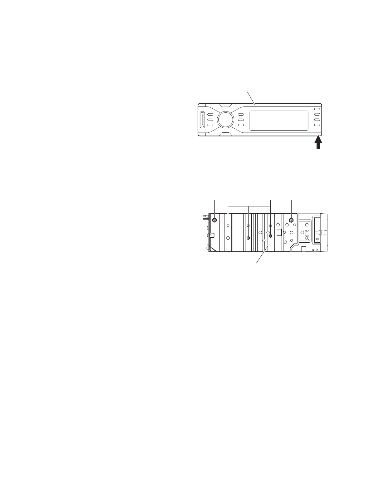
3.1.1 Removing the front panel assembly
(See Fig1)
(1) Push the detach button in the lower right part of the front
panel assembly.
(2) Remove the front panel assembly.
3.1.2 Removing the heat sink
(See Fig.2)
(1) From the left side of the main body, remove the two screws
A and three screws B attaching the heat sink.
Front panel assembly
Detach button
Fig.1
AAB
Heat sink
Fig.2
1-8 (No.MA161)
Page 5
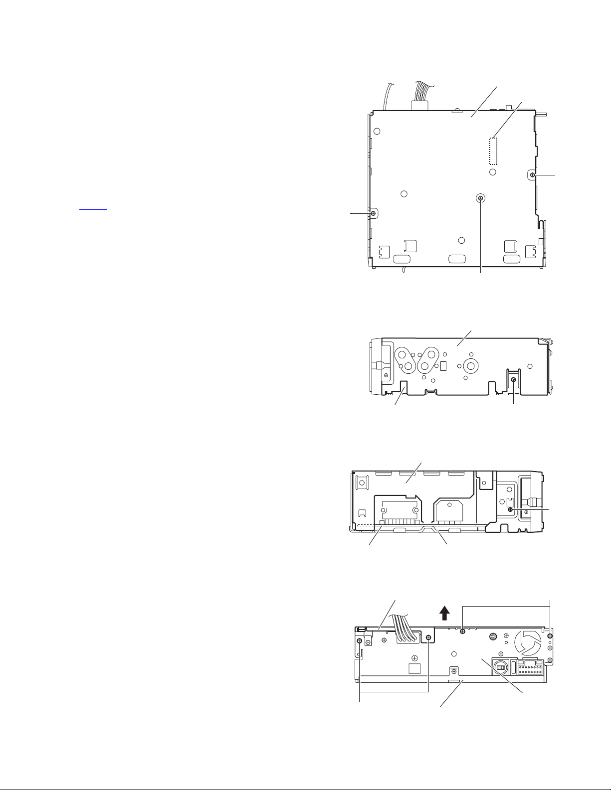
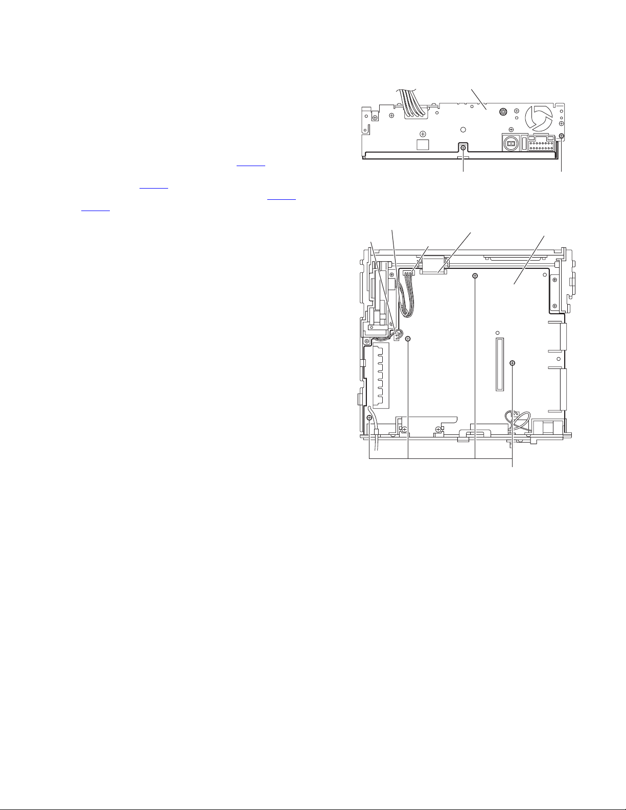
3.1.3 Removing the top chassis assembly
(See Figs.3 to 6)
• Prior to performing the following procedure, remove the front
panel assembly, heat sink.
Reference:
Remove the front panel assembly as required.
(1) From the bottom side of the main body, remove the two
screws C and screw D attaching the top chassis assembly
to the bottom chassis assembly. (See Fig.3)
(2) From the both and rear sides of the main body, remove the
six screws E attaching the top chassis assembly to the bottom chassis assembly. (See Figs.4 to 6)
(3) Lift the top chassis assembly in the direction of the arrow,
and disconnect top chassis assembly from the connector
on the main board. (See Figs.3 and 6)
CN601
(4) Take out the top chassis assembly from the bottom chassis
assembly.
Bottom chassis assembly
CN601
C
C
D
Fig.3
Top chassis assembly
Bottom chassis assembly
Top chassis assembly
Main board
Top chassis assembly
E
Bottom chassis assembly
Bottom chassis assembly
E
Fig.4
E
Fig.5
E
Rear bracket
Fig.6
(No.MA161)1-9
Page 6
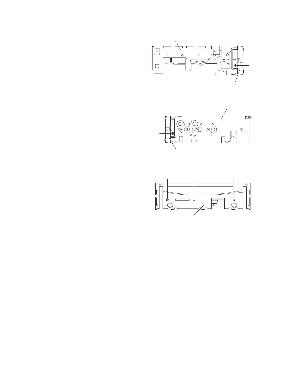
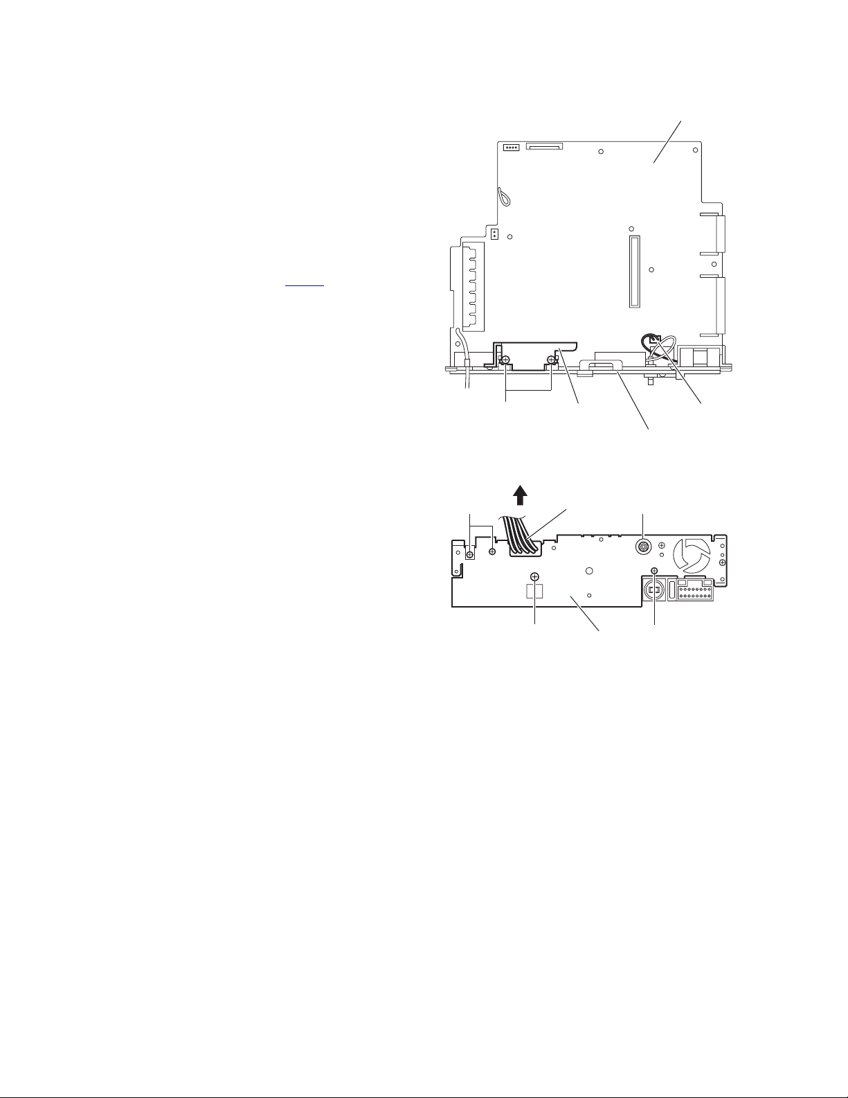
3.1.4 Removing the front chassis assembly
(See Figs.7 to 9)
• Prior to performing the following procedure, remove the front
panel assembly, heat sink and top chassis assembly.
(1) From the both sides of the top chassis assembly, remove
the two screws F attaching the front chassis assembly.
(See Figs.7 and 8)
(2) From the front sides of the top chassis assembly, remove
the three screws G attaching the front chassis assembly.
(See Fig.9)
(3) Take out the front chassis assembly from the top chassis.
Top chassis assembly
F
Front chassis
Fig.7
Top chassis assembly
F
Front chassis
Fig.8
Front chassis assembly
Fig.9
G
1-10 (No.MA161)
Page 7
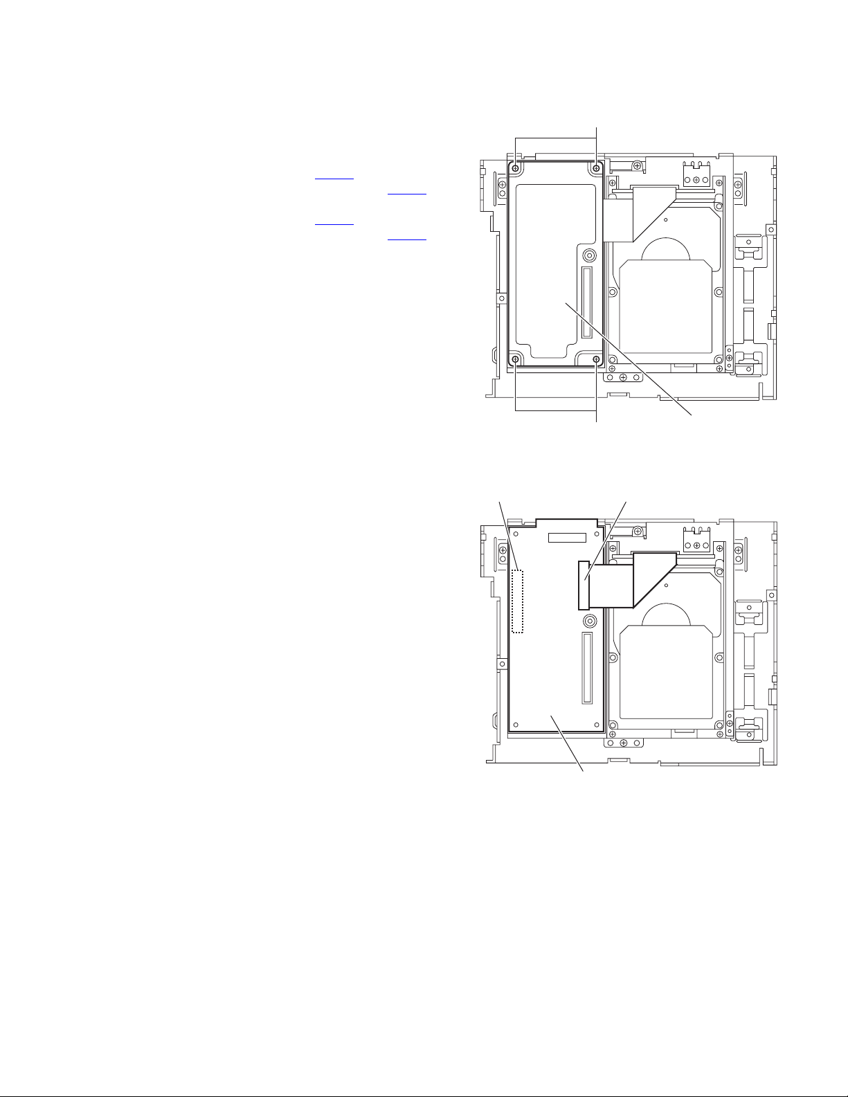
3.1.5 Removing the CPU board
(See Figs.10 and 11)
• Prior to performing the following procedure, remove the front
panel assembly, heat sink and top chassis assembly.
(1) From the inside of the top chassis assembly, remove the
four screws H attaching the CPU case (bottom). (See
Fig.10)
(2) Release the lock of the connector CN561
board, disconnect the card wire from the connector CN561
(See Fig.11)
(3) Release the lock of the connector CN531
board, disconnect the card wire from the connector CN531
(See Fig.11)
(4) Take out the CPU board from the top chassis assembly.
on the CPU
on the CPU
H
.
.
CPU case(botom)
H
Fig.10
CN531
CN561
CPU board
Fig.11
(No.MA161)1-11
Page 8
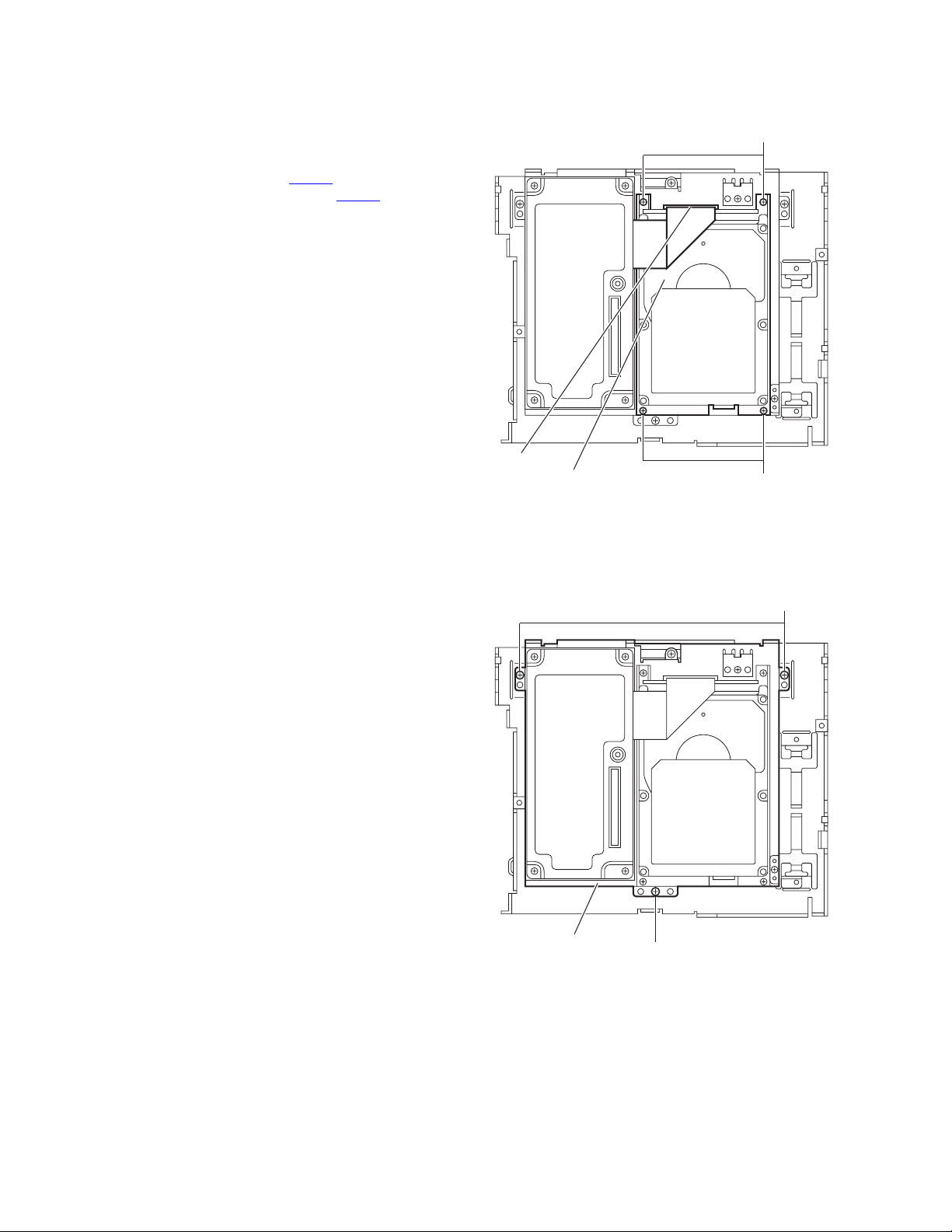
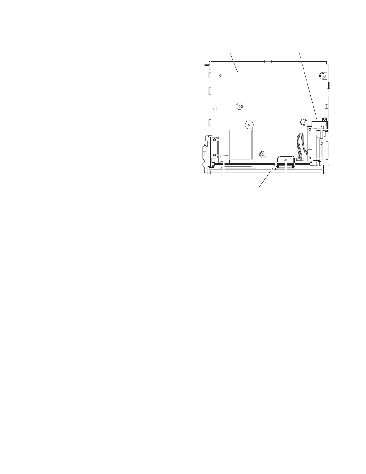
3.1.6 Removing the HDD
(See Fig.12)
• Prior to performing the following procedure, remove the front
panel assembly, heat sink and top chassis assembly.
(1) From the inside of the top chassis assembly, remove the
four screws J attaching the HDD.
(2) Release the lock of the connector CN562
connect the card wire from the connector CN562.
(3) Take out the HDD from the top chassis assembly.
3.1.7 Removing the DVD
(See Fig.13)
• Prior to performing the following procedure, remove the front
panel assembly, heat sink, front chassis assembly and top
chassis assembly.
(1) From the inside of the top chassis assembly, remove the
three screws K attaching the DVD.
(2) Take out the DVD from the top chassis assembly.
on the HDD, dis-
CN562
HDD
J
J
Fig.12
K
1-12 (No.MA161)
DVD
K
Fig.13
Page 9
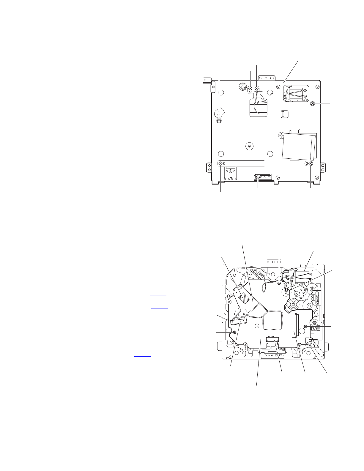
3.1.8 Removing the main board
(See Figs.14 and 15)
• Prior to performing the following procedure, remove the front
panel assembly, heat sink and top chassis assembly.
(1) From the rear side of the bottom chassis assembly, remove
the screws M and N attaching the rear bracket to the bottom chassis assembly. (See Fig.14)
(2) From the top side of the bottom chassis assembly, remove
the four screws P attaching the main board to the bottom
chassis assembly. (See Fig.15)
(3) Release the stopper of the connector CN751
board in an upward direction, disconnect the card wire from
the connector CN751
(4) Disconnect the wire from the connectors CN391 and
on the main board. (See Fig.15)
CN705
Reference:
After connecting the wires, fix the wires with the wire
holder.
(5) Take out the main board from the bottom chassis assem-
bly.
. (See Fig.15)
on the main
Wire holder
CN391
CN705
Rear bracket
MN
Fig.14
CN751
Main board
Fig.15
P
(No.MA161)1-13
Page 10
3.1.9 Removing the rear bracket
(See Figs.16 and 17)
• Prior to performing the following procedure, remove the front
panel assembly, heat sink, top chassis assembly and main
board.
(1) Remove the two screws Q attaching the wire holder to the
rear bracket. (Figs.16)
(2) From the rear side of the main board, remove the wires
from the rear bracket in the direction of the arrow. (See
Fig.17)
(3) Remove the two screws R and screws S and U attaching
the rear bracket to the main board. (Figs.17)
(4) Remove the nut T attaching the GPS antenna terminal.
(See Fig.17)
(5) Disconnect the wire from the connector CN381
board. (See Fig.16)
(6) Take out the main board from the bottom chassis assem-
bly.
on the main
Main board
Q
R T
Wire holder
Wire
Rear bracket
S
Rear bracket
Fig.16
Fig.17
CN381
U
1-14 (No.MA161)
Page 11
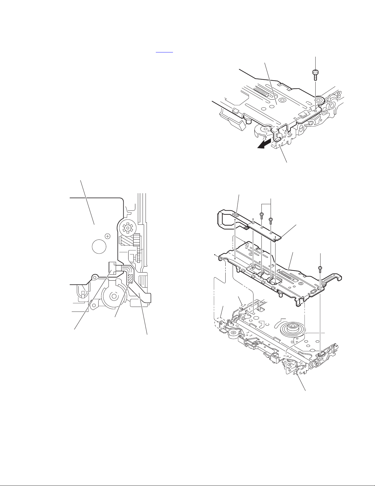
3.1.10 Removing the gear bracket unit
(See Fig.18)
• Prior to performing the following procedure, remove the front
panel assembly, heat sink, top chassis assembly and main
board.
(1) From the top side of the bottom chassis assembly, remove
the screw V attaching the FPC guide.
(2) Remove the five screws W attaching the gear bracket unit
to the bottom chassis.
Reference:
When attaching the screws V and W, apply a locking
agent them.
(3) Take out the gear bracket unit from the bottom chassis.
Bottom chassis Gear bracket unit
W
FPC guide
Fig.18
V
W
(No.MA161)1-15
Page 12
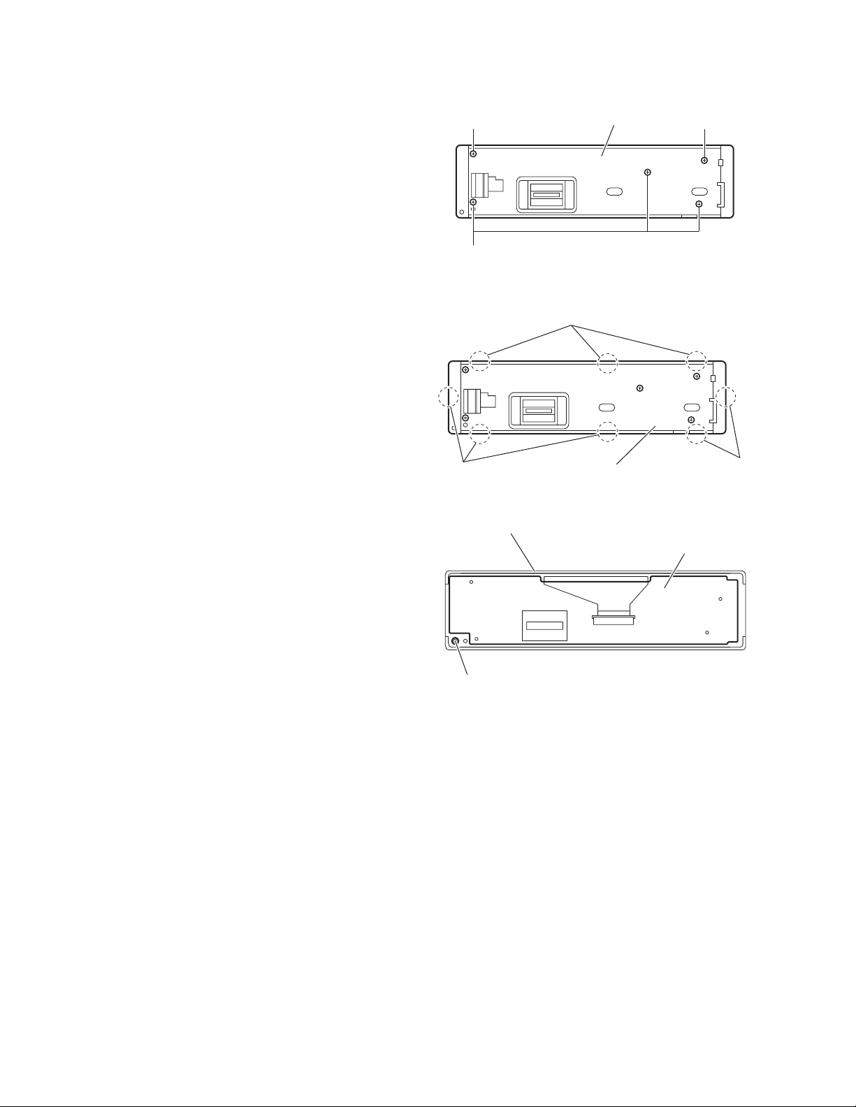
3.1.11 Removing the switch board
(See Figs.19 to 21)
• Prior to performing the following procedure, remove the front
panel assembly.
(1) From the rear side of the front panel assembly, remove the
five screws X attaching the rear cover assembly to the front
panel assembly. (See Fig.19)
(2) Release the eight joints a of the front panel assembly and
remove the rear cover assembly. (See Fig.20)
(3) Take out the switch board from the front panel assembly.
(See Fig.21)
Caution:
Take care not to lose the spring.
X
X
Rear cover assembly
Fig.19
Joints a
X
Joints a
Front panel assembly
Comp. spring
Rear cover assembly
Fig.20
Switch board
Fig.21
Joints a
1-16 (No.MA161)
Page 13
3.2 DVD mechanism assembly
3.2.1 Removing the chassis assembly
(See Fig.1)
(1) Remove the screw A attaching the lug wire.
(2) Remove the six screws B attaching the chassis assembly.
(3) Remove the chassis assembly.
B
B
A
Chassis assembly
B
3.2.2 Removing the mechanism control board
(See Fig.2)
Caution:
Before disconnecting the flexible wire extending from the DVD
pickup, solder the short-circuit point on the flexible wire using
a grounding soldering iron. If you do not follow this instruction,
the DVD pickup may be damaged.
(1) Turn over the body, and solder the short-circuit points on
the flexible wire extending from the DVD pickup.
(2) Disconnect the flexible wire from connector CN101
mechanism control board.
(3) Disconnect the card wire from connector CN201
mechanism control board.
(4) Disconnect the flexible wire from connector CN202
mechanism control board.
(5) Unsolder two soldered points a on the mechanism control
board and remove the wire extending from the feed motor.
(6) Remove the two screws C and screw D attaching the
mechanism control board.
Caution:
• As the flexible wire to be connected to CN101
attach it to the mechanism control board using a double
tape.
• After reassembling, unsolder the short-circuit points.
on the
on the
on the
, make sure to
Flexible wire
Double tape
CN101
C
Short-circuit points
Fig.1
C
Feed motor
CN401CN201
a
D
CN202
Mechanism control board
Fig.2
(No.MA161)1-17
Page 14
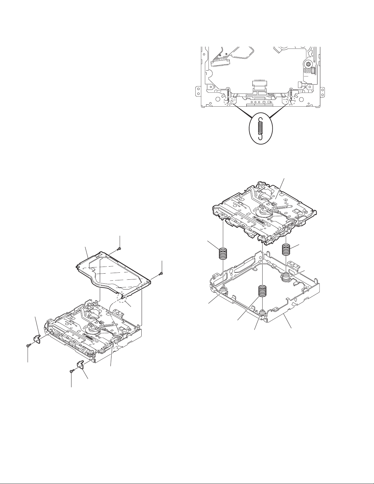
3.2.3 Removing the top cover
(See Fig.3)
(1) Remove the two screws E attaching the top cover on the
back of the body.
(2) Remove the top cover upward.
Reference:
When reassembling, set part b of the top cover under the
bending part c of the chassis frame.
3.2.4 Removing the mechanism section
(See Figs.3 to 5)
• Remove the top cover.
(1) From the bottom of the body, remove the screw E attaching
the lug wire. (See Fig.3)
(2) Remove the two screws F attaching the right and left stop-
pers on the front side. (See Fig.3)
(3) Remove the two floating springs on the bottom of the body.
(See Fig.4)
(4) Move the mechanism section upward and remove from the
chassis frame.
The three damper springs come off from the dampers.
(See Fig.5)
Caution:
• When reassembling, reattach the damper spring to the
damper respectively and insert the three shafts on the bottom of the mechanism to the dampers.
• Before inserting the shaft to the dampers, apply IPA to the
hole of damper.
Floating spring
Fig.4
Mechanism section
Stopper
F
Top cover
Stopper
F
Fig.3
E
E
b
c
Damper SP.(F)
(Silver)
Damper (F)
(Black)
Damper SP.(F)
(Silver)
Damper (F)
(Black)
Fig.5
Damper SP.(R)
(Red)
Damper (R)
(Purple)
Chassis frame
1-18 (No.MA161)
Page 15
3.2.5 Removing the clamper unit
(See Figs. 6 to 10)
• Remove the top cover and the mechanism section.
(1) Remove the clamper2 spring on the bottom of the mecha-
nism section. (See Figs.6.and 10)
(2) Release the part d of the clamper spring from the bending
part of the chassis base assembly. (See Fig.8)
(3) Move the clamper unit in the direction of the arrow and turn.
Release the two joints e and f, then remove the clamper
unit upward. (See Fig.6)
Clamper unit
3.2.6 Reattaching the clamper unit
(See Figs. 6 to 10)
(1) Attach the clamper spring to the clamper unit. (See Fig.9)
(2) Move the clamper unit to set the side joints e and f to each
boss of the chassis base assembly. Make sure that part g
is inserted to the notch of the chassis base assembly. (See
Figs.6 and 10)
(3) Move the part d of the clamper spring to the outside of the
bending part of the chassis base assembly. (See Fig.8)
(4) Attach the clamper2 spring to the chassis base assembly.
(See Figs.6 and 7)
Caution:
When reattaching, temporarily hook the end of the clamper
spring as shown in the figure to make the work easy. (See
Fig.9)
Clamper spring
f
Clamper2 spring
Chassis base assembly
Clamper2 spring
g
e
Fig.6
Chassis base assembly
Fig.7
(No.MA161)1-19
Page 16
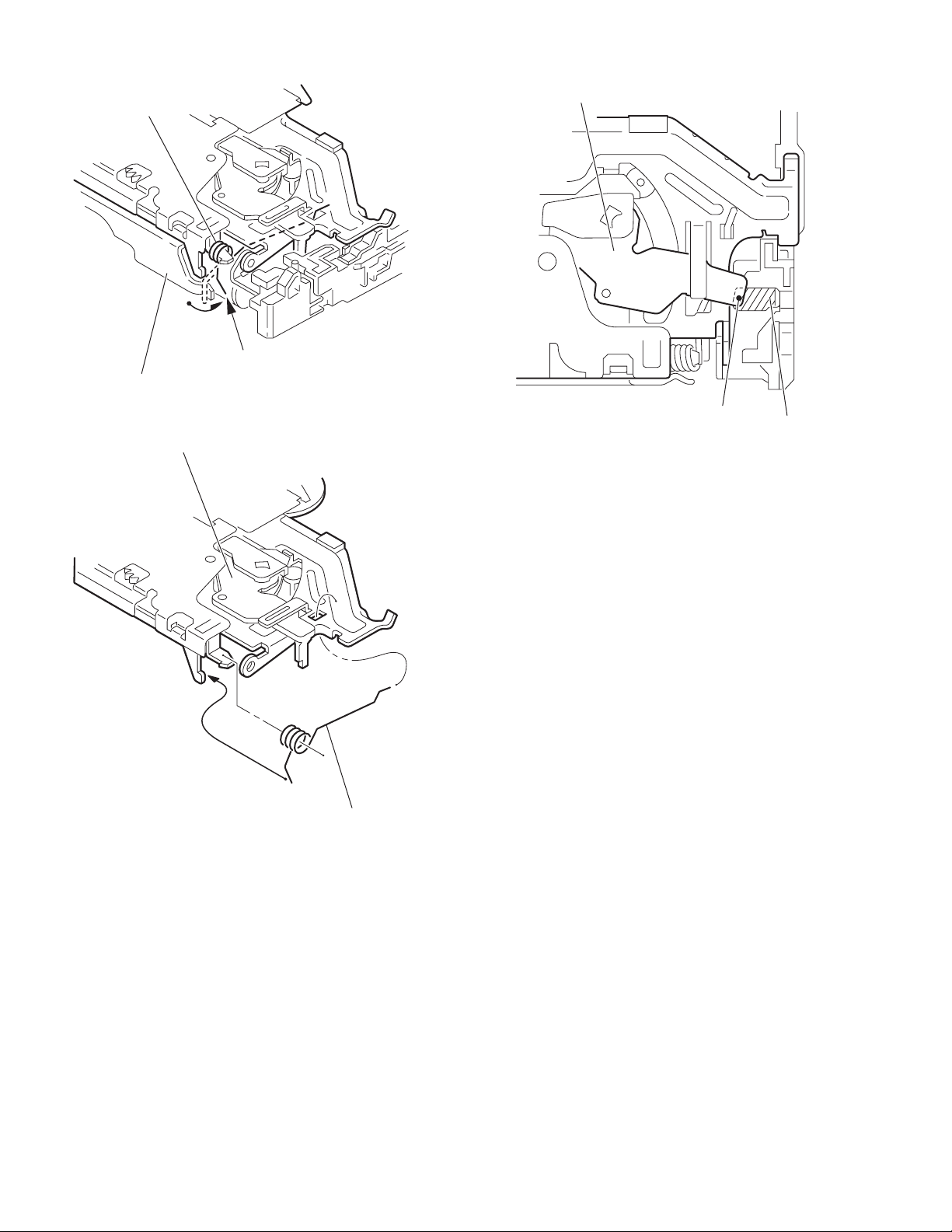
Clamper spring
Chassis base assembly
Clamper unit
d
Clamper unit
Fig.8
Fig.9
Clamper spring
Fig.10
g
Notch
1-20 (No.MA161)
Page 17
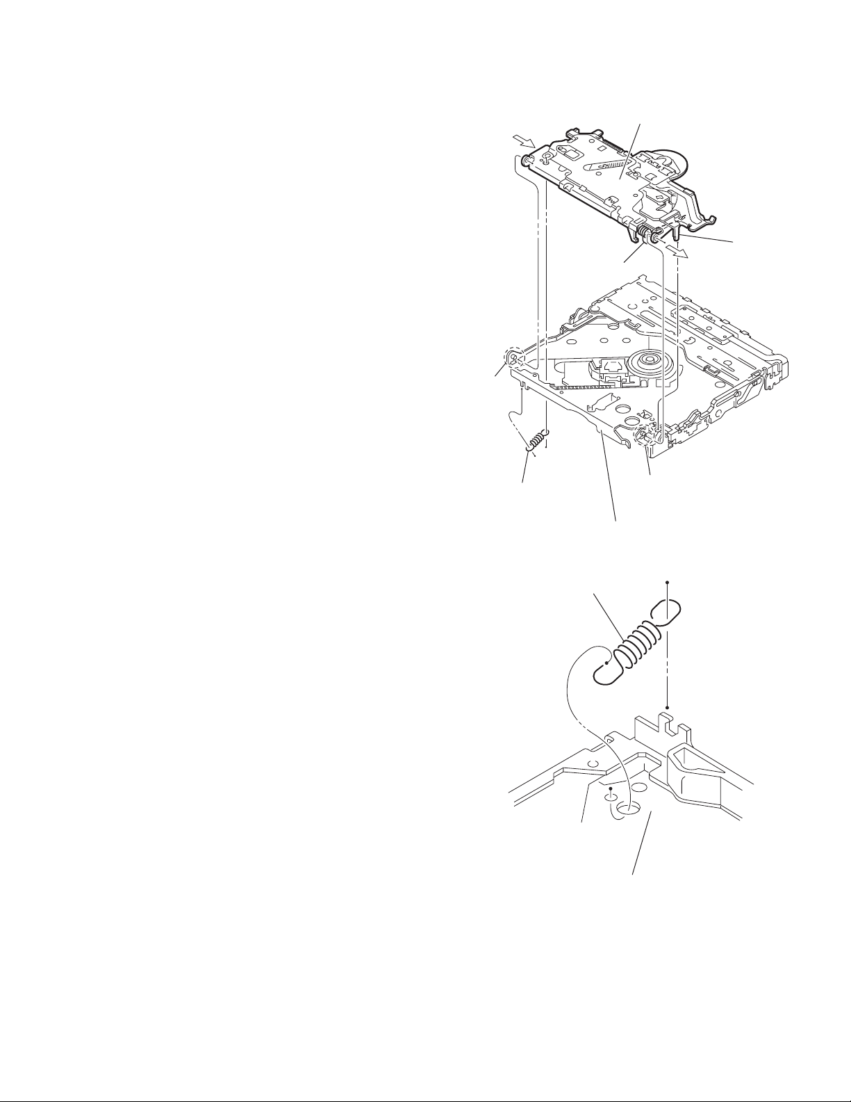
3.2.7 Removing the front unit
(See Figs.11 to 13)
• Remove the top cover and the mechanism section.
(1) Disconnect the flexible wire from connector CN202
mechanism control board at the bottom of the body. (See
Fig.11)
(2) Remove the screw G attaching the front unit on the top of
the body. (See Fig.12)
(3) Move the front unit toward the front to release joint h, and
release two joints j and k on the right side of the chassis
base assembly. Then remove the front unit upward. (See
Figs.12 and 13)
(4) Remove the two screws H attaching the switch board. (See
Fig.13)
Reference:
You can remove the switch board only without removing the
front unit.
Caution:
When reassembling, attach the flexible wire extending from
the switch board using the double tape. (See Figs.11 and 13)
Mechanism control board
on the
G
Front unit
h
Fig.12
CN202
Double tape
Fig.11
Flexible wire
Double tape
k
j
H
Switch board
Front unit
G
Fig.13
h
(No.MA161)1-21
Page 18
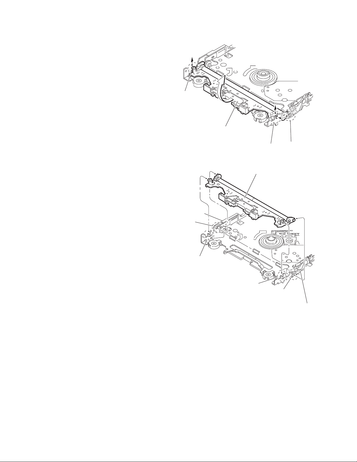
3.2.8 Removing the loading arm assembly
(See Figs.14 and 15)
• Remove the top cover, the mechanism section and the front
unit.
(1) From the top of the body, move the loading arm assembly
from the front side upward, and release the bosses from
the right and left joints m and n of the chassis base assembly.
(2) Release the boss from notch p of the connect arm on the
right side of the body, and release the boss from notch q of
the slide cam assembly on the left side.
n
Loading arm assembly
Side cam
assembly
q
n
m
Fig.14
Loading arm assembly
m
p
p
Connect arm
1-22 (No.MA161)
Fig.15
Page 19

3.2.9 Removing the rod (L)(R) and roller assembly
r
(See Figs.16 and 17)
• Remove the top cover, the mechanism section, the front unit
and the loading arm assembly.
(1) Release the rod (L) and (R) from the joints r at the bottom
of the loading arm assembly (See Fig.16)
(2) Remove the roller assembly from the loading arm assem-
bly. (See Fig.17)
(3) Remove the two collars and washer from the roller assem-
bly. (See Fig.17)
Caution:
After attaching the loading arm assembly to the roller assembly, attach the rod (L) and (R). Attach the rods to the right and
left collars of the roller. (See Fig.16)
When reattaching the rod (L) and (R) to the loading arm assembly, engage each joint as shown in Fig.15. As joints r of the
rod (L), let the rod through r before reattaching it.
Collar
Collar
Rod(R) Rod(L)
r
r
Collar
Rod(L)
Rod(R)
r
Loading arm assembly
Fig.16
Roller assembly
Loading arm assembly
r
Rod(L)
r
Collar
Washer
Rod(R)
Fig.17
(No.MA161)1-23
Page 20

3.2.10 Removing the DVD pickup assembly
(See Figs.18 to 20)
• Remove the mechanism control board.
(1) From the bottom of the body, turn the feed gear in the di-
rection of the arrow to move the DVD pickup outwards.
(See Fig.18)
(2) Remove the screw J attaching the thrust spring. (See
Fig.18)
(3) Remove the DVD pickup assembly upward on the L.S.gear
side and release from sub shaft at joint s Move the lead
screw of the DVD pickup assembly in the direction of the
arrow to release from joint t. (See Fig.19)
Caution:
• When releasing the lead screw at joint t, the L.S.collar
comes off at the end of the lead screw.
When reassembling, reattach the L.S.collar to the lead
screw and engage joint t. (See Fig.19)
• When reattaching the L.S.collar, reattach it to the point
s of the lead screw, and to the rod (M).
Make sure that the L.S.collar is set on the rod (M)
spring. (See Fig.19)
(4) Remove the screw K attaching the rack spring and rack
plate on the DVD pickup. (See Fig.20)
(5) Pull out the lead screw. (See Fig.20)
Caution:
Perform adjustment after replacing the pickup.
DVD Pickup assembly
DVD Pickup assembly
Feed gear
Thrust spring
Fig.18
L.S.collar
t
J
Rod(M)
Lead screw
Sub shaft
L.S.collar
s
Rack spring
Rack plate
DVD Pickup
L.S.gear
Fig.19
K
Lead screw
Fig.20
1-24 (No.MA161)
Page 21

3.2.11 Removing the spindle motor
r
(See Fig.21)
• Remove the mechanism control board.
Remove the two screws M attaching the spindle motor on the
bottom of the body.
Caution:
Perform adjustment when reattaching the spindle motor.
3.2.12 Removing the feed motor assembly
(See Figs.22 and 23)
• Remove the mechanism control board.
(1) Remove the feed TRI. spring on the bottom of the body.
(See Fig.22)
(2) Remove the two screws N attaching the feed motor assem-
bly. (See Fig.22)
(3) Remove the slit washer from the motor H. assembly and
pull out the worm wheel. (See Fig.23)
(4) Remove the two screws P attaching the feed motor. (See
Fig.23)
Spindle motor
M
Fig.21
Feed TRI. spring
N
Feed motor assembly
Fig.22
Slit washer
Worm wheel
Feed moto
P
Motor H. assembly
Fig.23
(No.MA161)1-25
Page 22

SECTION 4
ADJUSTMENT
4.1 Test instruments required for adjustment
(1) Digital oscilloscope (100MHz)
(2) Jitter meter
(3) Digital tester
(4) Electric voltmeter
(5) Tracking offset meter
(6) Test Disc : VT501 or VT502
(7) Extension studs : STDV001-3P
4.3 Connection method
Connection procedure
(1) Attach the front chassis assembly to the main board.
(2) Connect the front panel assembly to the main board.
(3) Attach the heat sink and rear bracket to the main board.
(4) Attach the extension studs to the DVD mechanism assembly.
(5) Attach the CPU board and HDD assembly with a card wire to the main board connecter.
(6) Connect the card wire from the CPU board to the DVD mechanism assembly.
DVD mechanism assembly
4.2 Standard measuring conditions
Power supply voltage DC14.4V(11 to 16V)
Load impedance 4Ω
Output Level 20kΩ
Caution:
Be sure to attach the heat sink and rear bracket onto the power
amplifier IC and regulator IC respectively, before supply the
power. If voltage is applied without attaching these parts, the
power amplifier IC and regulator IC will be destroyed by heat.
Extension studs
STDV001-3P
Heat sink
CPU board
Main board
Rear bracket
Isolator (cardboard etc.)
HDD assembly
1-26 (No.MA161)
Page 23

4.4 Jitter value conversion table
Indicated
on the LCD
EF56
EF22
EEEE
EEBA
EE86
EE52
EE1E
EDEA
EDB6
ED82
ED4E
ED1A
ECE6
ECB2
EC7E
EC4A
EC16
EBE2
EBAE
EB7A
EB46
EB12
EADE
EAAA
EA76
EA42
EA0E
E9DA
E9A6
JIT OUT JIT OUT JIT OUT
4.7
4.8
4.9
5.0
5.1
5.2
5.3
5.4
5.5
5.6
5.7
5.8
5.9
6.0
6.1
6.2
6.3
6.4
6.5
6.6
6.7
6.8
6.9
7.0
7.1
7.2
7.3
7.4
7.5
Indicated
on the LCD
E972
E93E
E90A
E8D6
E8A2
E86E
E83A
E806
E7D2
E79E
E76A
E736
E702
E6CE
E69A
E666
E632
E5FE
E5CA
E596
E562
E52E
E4FA
E4C6
E492
E45E
E42A
E3F6
E3C2
7.6
7.7
7.8
7.9
8.0
8.1
8.2
8.3
8.4
8.5
8.6
8.7
8.8
8.9
9.0
9.1
9.2
9.3
9.4
9.5
9.6
9.7
9.8
9.9
10.0
10.1
10.2
10.3
10.4
Indicated
on the LCD
E38E
E35A
E326
E2F2
E2BE
E28A
E256
E222
E1EE
E1BA
E186
E152
E11E
E0EA
E0B6
E082
E04E
E01A
DFE6
DFB2
DF7E
DF4A
DF16
DEE2
DEAE
DE7A
DE46
DE12
DDDE
10.5
10.6
10.7
10.8
10.9
11.0
11.1
11.2
11.3
11.4
11.5
11.6
11.7
11.8
11.9
12.0
12.1
12.2
12.3
12.4
12.5
12.6
12.7
12.8
12.9
13.0
13.1
13.2
13.3
Indicated
on the LCD
DDAA
DD76
DD42
DD0E
DCDA
DCA6
DC72
DC3E
DC0A
DBD6
DBA2
DB6E
DB3A
DB06
DAD2
DA9E
DA6A
DA36
DA02
D9CE
D99A
D966
D932
D8FE
D8CA
D896
D862
JIT OUT
13.4
13.5
13.6
13.7
13.8
13.9
14.0
14.1
14.2
14.3
14.4
14.5
14.6
14.7
14.8
14.9
15.0
15.1
15.2
15.3
15.4
15.5
15.6
15.7
15.8
15.9
16.0
(No.MA161)1-27
Page 24

4.5 Service mode
Note: After initialized should push the [RESET] key,
or should pull out a power code 30 seconds or more, and should surely reset a main unit.
Note: Do not turn off the power. The unit will not restart.
Note: Do not turn off the power. The unit will not restart.
Note
The new HDD of factory shipments is blank.
When exchanging new HDD at repair,
it needs copy of data from the master HDD by the HDD copy machine.
SOURCE
Setup to the service mode
Turn on the power.
Select to the [TUNER] source.
Press the key [SEL] [POWER] [SOURCE] over the two seconds.
MENU
1.Sensor Check 4.Tuner Adjustment 1.Version Check 4.Data Clear 1.DVD Area/Region 4.TMC Check Mode
2.Initial All 5.DVD Mecha Init 2.Firmware Update 5.Running Mode 2.DVD Check Mode 5.Self Check
3.GPS Init Check 6.GYRO Adjustment 3.Data Read 6.HDD Format 3.DVD NTSC/PAL 6.Full Clear
*Change the menu items rotate control dial.
*Select the mode push the [1] to [6] key.
*The [DISP/BACK] key is return of item.
1-28 (No.MA161)
SEL
POWER
CONTROL DIAL/OK
Service Mode Service Mode Service Mode
Sensor Check Indicate the sensors information
Spd pls : ** Spd pls: Speed pulse value
Gyro :**** . **
GPS : ********/********
Prk SW : 01 ON
Rvs SW : 00 F
Initial All
Initialize factory setup data.
GPS Init Check
Tuner Adjustment
DVD Mecha Init
GYRO Adjustment
Version Check
Main Ver :X. XXX YY Version of main microcomputer and ROM correction.
FP Ver :X XXX YY
Navi Ver :XXX Version of navigation microcomputer.
DVD Ver :XXXX Version of DVD unit.
DB Ver :EuropeX. X. X. X Version of map database.
Version Check
Firmware Update
Rewriting the firmware of the navigation microcomputer. Procedure is the following.
1) Making of SD card for Update.
(SD card writer is connected with a personal computer, and software is copied.)
(1) SD card prepares 32 M bytes or more.
(2) Select the [FAT] file system. Format option is standard. Quick format is not chosen.
(3) Copy the firmware file to the route directory.
2)Updating
Form updating from the DVD-R/RW of the navigation microcomputer.
1) Making of the update disk.
2)Update
A
Sensor DATA
Tuner preset
User entry name
Error log
Note: After initialized should push the [RESET] key,
or should pull out a power code 30 seconds or more, and should surely reset a main unit.
Only the factory setup.
No use.
Only the factory setup.
No use.
Only the factory setup.
No use.
Only the factory setup.
No use.
(1) Insert the updated SD card.
(2) Select the [Firmware Update] from service mode.
(3) Press the [OK] key after [Firmware Update Start OK ? ] displayed.
(4) Flashing display the [Firmware Update Now Updating] in updating. It take about five minutes.
Note: Do not turn off the power. The unit will not restart.
(5) Power supply is shut off and supply again, it is automatically after update.
(6) Extract the SD card.
(1) Preparing of the DVD-R or DBD-RW.
Note: Do not use CD-R,CD-RW,DVD+R,DVD+RW.
(2) Make the [JVCDBUpdate] name folder.
Make the [FWUpdate] name folder in the [JVCDBUpdate] .
(3) Move to the two provide data fail to [FWUpdate] folder.
(4) Disk writing by the [Disk at once].
(1) Loading to updated disk.
(2) Press the [OK] key after [Firmware Update Start OK ? ] displayed.
(3) Flashing display the [Firmware Update Now Updating] in updating. It take about five minutes.
Note: Do not turn off the power. The unit will not restart.
(4) Power supply is shut off and supply again, it is automatically after update.
(5) Eject the disk after the [Please Eject] displayed.
For example, if 100Hz rectangle wave signal inputted from an oscillator,
it will become the display of [A0] etc.
Gyro : Output value from inside gyro
If a main unit is turned to right or left, a value will change.
GPS : Latitude and longitude value from GPS antenna.
Only of navigable area.
Prk SW: Detect the parking brake
01:ON
00:OFF
Rvs SW: Detect the reverse
01: BACK
00:FORWARD
Version of panel microcomputer and ROM correction.
Page 25

A
Note: After initialized should push the [RESET] key,
or should pull out a power code 30 seconds or more, and should surely reset a main unit.
Note: After formatted should push the [RESET] key,
or should pull out a power code 30 seconds or more, and should surely reset a main unit.
Note: After formatted should push the [RESET] key,
or should pull out a power code 30 seconds or more, and should surely reset a main unit.
Note: After self checked should push the [RESET] key,
or should pull out a power code 30 seconds or more, and should surely reset a main unit.
Note: After cleared should push the [RESET] key,
or should pull out a power code 30 seconds or more, and should surely reset a main unit.
Data Read Error History
1.Error History 1.DVD Error 4.System Error
2.Temperature 2.CDCH Error
3.GYRO adjust value 3.Panel Mecha Err
Error logs and data display
Data Clear
1.DVD Err Clr 4.Initial Name & DVD
2.CDCH Err Clr 5.Initial GYROData DVD Err Clr Clear of DVD error log.
3.P-Mecha Err Clr 6.Initial All
Running Mode (For technical examination)
HDD Format
1.Music Srv Format
2.SYS Data Format Music Srv Format All formatting of the HDD music data area.
DVD Area/Region Area suffix is [E]. Region [2] fixed.
DVD Check Mode
Press Any Key *Refer to DVD CHECK MODE.
DVD NTSC/PAL (For technical examination)
Data Read Mode Error History
Temperature Temperature data. (For technical examination)
GYRO Adjust Value
GYRO Adjust - OK GYRO adjusting value
Offset :XXXX
Factor :XX. XX
Data Clear Mode CDCH Err Clr Clear of CDCH error log.
P-Mecha Err Clear of control panel mechanism error.
Initial Name & DVD
Clear the user entry information, initialize the DVD error log and DVD menu setting value.
Initial GYROdata Initialize the GYRO value of the factory setup data.
Initial All Initialize factory setup data.
Note: After initialized should push the [RESET] key,
or should pull out a power code 30 seconds or more, and should surely reset a main unit.
HDD Format Mode
DVD Check Mode
Note: After formatted should push the [RESET] key,
or should pull out a power code 30 seconds or more, and should surely reset a main unit.
SYS Data Format All formatting of the VAVI (addres ets.) system recording data.
Note: After formatted should push the [RESET] key,
or should pull out a power code 30 seconds or more, and should surely reset a main unit.
DVD Error Error log of DVD.
E-1 :****** E02 :******
E-2 :****** E03 :******
E-3 :****** E04 :******
E01 :****** E05 :******
DVD Error
CDCH Error Error log of CDCH.
E-1 :****** E02 :******
E-2 :****** E03 :******
E-3 :****** E04 :******
E01 :****** E05 :******
CDCH Error
P-Mecha Error Error log of control panel mechanism.
E-1 :****** E02 :******
E-2 :****** E03 :******
E-3 :****** E04 :******
E01 :****** E05 :******
P-Mecha Error
System Error Error log of navigation microcomputer system.
TOTAL ERROR :** Total error counts.
E-1 : [E-1] is newly data.
E-2 : Error content
E-3 :
System Error
(For technical examination)
GYRO Adjust Value
(Not clear the servo learning data.)
00 :no error
Navi+Ent :HDD,SD system error.
Navi :Navigation system error.
Ent :HDD,SD system error.
SCI :Navigation microcomputer system error.
TMC Check Mode TMC Signal Check (Using factory setup)
TMC Info Mode (For technical examination)
Self Check Self check as following
Self Check OK ! GYRO check
ERROR XXXX Check of GYRO data in state of rest.
Self Check Check of GYRO data in AD value.
Full Clear Continuously execute of the [Initial All] and [HDD Sev Format].
(Using factory setup)
Note: After cleared should push the [RESET] key,
or should pull out a power code 30 seconds or more, and should surely reset a main unit.
GPS check
Check of GPS output.
Check of UART output form GPS unit.
HDD check
Check of R/W on the HDD.
Error code
0004: GYRO error Trouble of GYRO
0005: GPS error Trouble of GPS unit
0007: HDD error Trouble of HDD
Note: After self checked should push the [RESET] key,
or should pull out a power code 30 seconds or more, and should surely reset a main unit.
(No.MA161)1-29
Page 26

4.6 NAVI engineer mode
Setup to the NAVI engineer mode
Turn on the power. Select to the [NAVI] mode
Press the key [SEL] [NAVI/AV] [OK] over the two seconds.
MENU
1.DIL FILE COPY 4.GPS RAW DATA
2.NAVILOG COPY 5.SIMULATION DIL FILE COPY (For technical examination)
3.SENSOR DATA 6.SYS_DATA COPY Copy the log data file to SD card.
NAVI ENGINEERING
NAVILOG COPY Copy log data to SD card at navigation guidance.
SENSOR DATA
GPS LAW DATA (No use)
SIMULATION Change ON/OFF of the simulation mode.
(Using troubleshooting to the designer)
Learning Level:* Level(0-4)
Gyro:**** Gyro value (0000-4096)
**cm/pls: Centimeter per one pulse
Speed:**km/h Speed
**,*pps Pulse count of speed
Backgear:****** Direction
Low or High Position of back gear
GPS SAT:* Receive count of GPS saterite
HDOP:*,* HDOP value(0.0-99.9)
Simulation mode : Using simulate with out sensor.
(It can use uncompleted Vp calibration.)
Display the sub menu after select the [SIMULATION]
1.OFF
2.ON
SIMULATION
Display after ON select.
SIMULATION MODE
JVC
The origin in simulation mode is determined as follows by language setup.
Language Origin
DANSK Copenhagen
DEUTSH Berlin
ENGLAND UK London
ENGLAND US London
ESPANOL Madrid
FRANCAIS Paris
ITALIANO Roma
NEDERLANDS Amsterdam
SVENSKA Stockholm
*Resetting the SIMULATION mode by the [ACC off] or power off or [RESET].
SYS_DATA COPY (For technical examination)
1-30 (No.MA161)
Page 27

4.7 ROM correction of the main microcomputer and panel microcomputer
The RAM correction of the main microcomputer and panel microcomputer from the CD-R/RW or DVD-R/RW.
4.7.1 Making the disk for ROM correction
(1) Prepare the CD-R or CD-RW or DVD-R or DVD-RW.
Note:
Do not use DVD+R and DVD+RW.
(2) The two provided files put into the [ROOT].
Do not make file folder.
(3) The disk write by the [Disk at once].
4.7.2 ROM correction
(1) Loading the ROM correction disk.
(2) Displayed the [ROM CORR] in updating.
It takes about ten minutes.
Note:
Do not turn off the power. The unit will not restart.
(3) Eject the disk after [OK xxxx Please Eject] displayed.
Note:
The numbers [xxxx] for microcomputer management within factory.
(4) After the ROM correction, should reset a main unit.
(No.MA161)1-31
Page 28

4.8 DVD unit check mode
When change the item must be press the [OK] key up to the execute.
Check item list
No. A/D key DVD unit operation LCD indication and contents
[1]
1
[2]
2
[3]
3
[4]
4
[5]
5
[6]
6
Rotate
7
control dial to
clockwise
Rotate
8
control dial to
counterclockwise
[SOURCE]
9
[MODE]
10
Start at normal speed
(After start, it is measured JITTER on the
internal position)
Tracking off on the outermost position of CD
Tracking off on the innermost position of CD
CD_LD lights and laser current is displayed
DVD_LD lights and laser current is displayed
DVD x1 jitter measuring mode
(for use in mechanism measurement)
Indication of EEPROM contents
(0x00-0xFF)
Indication of EEPROM contents
(0x00-0xFF)
Initialize of EEPROM contents
Indication of temperature
CURRENT:
JITTER:
CURRENT:
JITTER:
CURRENT:
JITTER:
CURRENT:
JITTER:
ADDRES:
DATA:
ADDRES:
DATA:
TEMP DATA:
Laser current value
Jitter value
For EF phase
For EF phase
Laser current value
Jitter value
Laser current value
Jitter value
Laser current value
Jitter value
EEPROM address
EEPROM contents
EEPROM address
EEPROM contents
Temperature
[DISP]
11
[TP]
12
[OK]
13
[OK]
14
(Press two seconds)
[EJECT]
15
[EJECT]
16
Note
Press key [1] before press the key [2] or [3] .
Press key [DISP] before the key [1] or [OK] pressed and confirm the indication of jitter value on the LCD.
No.6 item is only of first layer on DVD disk. Even other disks start of first layer on DVD disk.
When No.1 or No.13 item key pushed after jitter indication, a focus jump is executed.
(Only second layer of DVD disk)
Stop a disk before OPEN, CLOSE for all means. (OPEN and CLOSE are not executed in a disk rotate.)
The check mode can be exited either by pressing the [POWER] key or resetting the unit.
Search & jitter measurement to an appointed
position of DVD
Setting of MONITOR terminal
DVD normal speed start up
(After start, it is measured JITTER on the
internal position)
Disc stopped & LD-OFF
OPEN
CLOSE
PLACE:
JITTER:
DATA:
CURRENT:
JITTER
CHECK
CHECK
CHECK
0x00--0x06
(Measuring position with VT-501)
Jitter value
0x00-0x0c
Laser current value
Jitter value
1-32 (No.MA161)
Page 29

5.1 16PIN CORD DIAGRAM
SECTION 5
TROUBLESHOOTING
GN
GN/BK
VI/BK
VI
PK
BL/WH
RD
BK
YL
RD
BL/WH
OR/WH
WH
WH/BK
GY/BK
GY
BR
VI/WH
OR/WH
YL
MEMORY
VI/WH
PK
BK
BR TEL
BK
RD
BL
WH
BR
L.GN
Choking Coil
ACC
REMOTE
REVERS
SPEED
GND
ILL
Black
Red
Blue
White
Brown
Light Green
GN
VI
GY
YL
OR
PK
Green
Violet
Gray
Yellow
Orange
Pink
RD
PK
VI/WH
BL/WH
RD
YL
RD
BL/WH
VI/WH
PK
BR
YL
OR/WH
BK
RR
FR
FL
RL
REMOTE
ILL
VI
VI/BK
GY
GY/BK FR-
WH
WH/BK
GN RL+
GN/BK
L.GN
Rear Right
Front Right
Front Left
Rear Left
Remote
Illuminations Control
RR+
RR-
FR+
FL+
FL-
RL-
PARKING
ACC
TEL
GND
MEMORY
PARKING
ANT
ACC Line
Telephone Muting
Ground
Memory Backup Battery+
Parking Brake
Auto Antenna
VI
GY
WH
GN
VI/BK
GY/BK
WH/BK
GN/BK
REVERS
Revers Gear Signal Lead
SPEED
Speed Signal Lead
(No.MA161)1-33
Page 30

SCHEMATIC DIAGRAMS
HDD NAVIGATION/DVD RECEIVER
KD-NX901
CD-ROM No.SML200506
Area suffix
E ------------- Southern Europe
Lead free solder used in the board (material : Sn-Ag-Cu, melting point : 219 Centigrade)
Contents
Block diagram
Standard schematic diagrams
Printed circuit boards
COPYRIGHT 2005 Victor Company of Japan, Limited.
2-1
2-2
2-8 to 11
No.MA161SCH
2005/6
Page 31

Block diagram
FOCUS
&
TRACKING
COIL
PICK UP
LOAD&FEED
MOTOR
SPINDLE
MOTOR
SW1 to SW3
LCD
DISPLAY
DVD section
CN101
A,B,C,D,E,F,F1CD,F2CD,F1DVD,F2DVD
VREFH,HANGUP,RF+,RF-,LPC1,LPC2
CPU section
A2 to A23
D0 to D31
-WE0/DQM0
-WE2/-DQM2
-RD/-CASS
-CS0
IC521
FLASH
ROM
IC522
FLASH
IC71
RDS
ROM
IC541
DSP
DETOUT
PLLDI2
PLLCE2
PLLDA2
PLLK2
RDSDA2
RDSSCK2
LD+
Q101
Q102
LD+
Q103
Q104
F+,FT+,T-
FLM+
M
M
FLM-
H1+,H1H2+,H2H3+,H3-
CN201
SM1 to SM3
VH
IC201
DRIVER
IC251
SP MOTOR
DRIVER
IC399
SDRAM
IC398
FLASH ROM
CN202
SW1 to SW3
SW4,TRVSW
SW4,SW5
LPCO1
DVDLDCUR
LPCO2
CDLDCUR
/DRVMUTE
TRDRV
FODRV
VHALF2
TRSDRV
DRVCONT
LM
SBRK
SPDRV
/SPMUTE
FG
MA0 to MA11
MDQ0 to MDQ15
DQM0,DQM1
BA0,BA1,MCK
NWE,NCSM
NCAS,NRAS
EXADT0 to EXADT15
EXADR16 to EZADR20
EXDAT0 to EXDAT15
NEXOE,NEXCE
NEXWE,/FL_RST
TRVSW
SW2,SW3
SW1,SW4
IC301
DV2.1
ERROR
AVR TM
STVLD
STCLK
STD0 to STD7
STENA
DAC4OUT
IECOUT
EJREQ
LRMUTE
UCS,SCS
SACK,SCLK
U2SDT,S2UDT
CPURST
EPDI
EPDO
EPSK
EPCS
IC481
EPROM
CN401
ANT
IC501
CPU
SCS
SACK
-UCS
RXD2,TXD2
TXD,RXD
SCK,-NAVI_ACK
-MAIN_REQ
SYS_MUTE
-ADC_CS,RVS
-RESET
CN531
SW1,SW4,DAC4OUT,SPDIF,LRMUTE,SDO0,EJECT
Main section
J1
TU1
DVD_DATA
DVD_WS
DVD_BCK
LRCKA
BCLKA
SDO0
FM/AM
TUNER
IC11
-IRL0 to -IRL3,SPD_OUT,CKOUT
-MICS
-MILP
MIACK
END_DEC
DETECTER
TU2
FM TMC
TUNER
DSPNIT,SD,BUSENABLE,DSP_SDA
DSP_SCK,RFON,RDS_SDA,RDS_SCK
BUS3
A5 to A10,A12
D0 to D15
-RD/-CASS
-WE0/-DQM0
LRCKA,BCLAK
SDATA_0
GATE,-MICK
DSP_RST
DSP_REQ
END-DEC
BUS2
STD[0] to STD[7]
STVALID,STCLK
SRST,S2UDT
STEN,-
U2SDT,-UCS,SCLK
CN501
CN601
SW1,SW4,NAVI_RXD
NAVI_TXD,NAVIDACK
NAVI_SCK,MAIN_REQ
NAVIACK,NAVIRST
SD_SW,EJ,SDIN
EJ,SDIN
IC702
EPROM
-CS4
IC531
ASIC
ADC_CLK
ADC_DATA
ADC_CS
A2 to A16
D0 to D31
-WE0/DQM0
-WE2/-DQM2
RD/-WR
-RD/-CASS
-RAS,-CS3
CKE,CKIO
DQM1,DQM3
-SD_RET
-SD_IRQ
BUS2
MCLK,BCLKB
SDDATA_1,LRCKB
-CODEC_RST
BUS1
ADC_CLK,ADC_DATA
VG_FLMUTE
VG_FRMUTE
GPS_TX,GPS_RX
PPS,SPD_IN
-RESET
LRCKA,BCLKA
STD[4] to [6]
IC603
AD CONVERTER
PM+
PM-
IC701
CPU
PIMKICK
CODE1 to 3
BUSSCK,BUSINT
-BUSI/O,BUSI/O
BUSSO,BUSSI
IC512
SDRAM
IC511
SDRAM
-WE0/-DQM0
-RD/-CASS
CKIO,-CS_SD
IC551
SD CARD
VOICEOUT
PPS,RXD2
TXD2
SPDIF
A5 to 11
D0 to D15
VOICEGUIDE
IC602
GYRO SENCER
IC601
GPS RECIVER
IC462
OPTICAL JACK
IC391
MOTOR
DRIVER
IC781
JVC BUS
A5 to A7
D0 to D15
-HDD_CS0
-HDD_CS1
-ATA_RDY
-ATA_RET
-ATAIRQ
IC591
DAC
-DIOR
-DIOW
SI/SO
SCK
CH-L
CH-R
CN561
CN705CN391
CN902
CN562
CN563
FRONT
PANE L
DRIVE
CHANGER
TO
HDD
DSP
FRONT LINE OUT
LCD & Key switch section
EN832
ENCODER
OCS,CS,RES
CN851
RS,WR,RD
DB0 to 7
S8301 to S8316
KEY MATRIX
KEY0
KEY1
KEY2
ENC1
ENC2
REMOCON PS2-LCD
IC841
REMOCON
FLASH ROM
A0 to A20
D0 to D7
WE,RE,CSO
IC821
IC801
CPU
KEADATA
DISPSCK
SBD,STB
SBRST
S.T.REMOCON
DISPCE
DISPDATA
D8601 to D8613
D8619 to D8622
LIGHTING
DISPLAY
CN801
CN751
PICT_TXD
PICT_RXD
DAC4OUT
VOICEOUT
VG_FRMUTE
VG_FLMUTE
DAC_FL
DAC_FR
IC401
SERECTER
SBRST,DISPSCK,DISPDATA,DISPCE,DETACH,KEYDATA,PS2
IC451
DRIVER
IC 111
SW
SUB OUT
FL
RL
FR
RR
V-FL
V-FR
IC121
AMP
IC221
AMP
FLOUT
RLOUT
FROUT
RROUT
IC101
LPF
FL
FR
RL
RR
E.VOLUME
IC102
IC951
POWER
AMP
EACH BLOCK
PBRK,S.T.REMOCON
FLOUT,FROUT
VIDEO_OUT
SUB WOOFER OUT
RLOUT,RROUT
FR+,FR-,,FL+,FLRL+,RL-,RR+,RR-
IC901
REGULATOR
CN752
VIDEO OUT
STEERINGREMOTE
PARKING BREAK
CN121
REAR LINE OUT
SUB WOOFER OUT
CN901
SPEAKER
BATTERY
2-1
Page 32

Standard schematic diagrams
Main section (1/2)
CN601
RFON
PLLDI2
PLLCE2
PLLDA2
PLLCK2
RDSDA2
RDSSCK2
SD
SM2
PMKICK
PM+
PM-
BUSENABLE
RST_7730
DSP_SCK
DSP_SDA
RDS_SDA
RDS_SCK
4.5V
ON3.3V
SW
V-FL
V-FR
VOICEOUT
FL
FR
RL
To SHEET 2
RR
VG_FRMUTE
VG_FLMUTE
DSPINIT
VOLDA
VOLCK
VOL-MUTE
CH.L
CH.R
DVD_DATA
DVD_BCK
DVD_WS
SDO0
LRCKA
BCLKA
9V
ON5V
CD8V
LED
GND
CN751
QGF1041C1-16W
16
15
14
13
12
11
10
CN801 (SHEET 6)
R7503
9
8
7
6
5
4
3
2
1
TP73
D7501 MA8056/M/-X
D7502 MA8056/M/-X
D7503 MA8056/M/-X
D7504 MA8056/M/-X
D7505 MA8056/M/-X
D7506 MA8056/M/-X
1k
D7507 MA8056/M/-X
QGB0812L2-90X
C617 100P
D7508 MA8056/M/-X
123456789
R647 100
R648 100
R632 100
PICTTXD
SW4
SW1
C618 100P
HDD5V
CPU3.3V
BUP3.3V
PPS
RXD2
TXD2
RVS
BSIGNAL
SPD_IN
SPULSE
ADC_CLK
ADC_DATA
ADC_CS
PLLDI2
PLLCE2
PLLDA2
PLLCK2
RDSDA2
RDSSCK2
PMKICK
BUSENABLE
RST_7730
DSP_SCK
DSP_SDA
RDS_SDA
RDS_SCK
ON3.3V
VOICEOUT
VG_FRMUTE
VG_FLMUTE
DSPINIT
VOLDA
VOLCK
VOL-MUTE
DVD_DATA
DVD_BCK
DVD_WS
LRCKA
BCLKA
S.T.REMOCON
PANEL3.3V
SBRST
PICT_TXD
ACC5V
PICT_RXD
D7509 MA8056/M/-X
D7510 MA8056/M/-X
RFON
SM2
PM+
PM-
4.5V
V-FL
V-FR
CH.L
CH.R
SDO0
ON5V
CD8V
LED
2.2kR7501
101112131415161718192021222324252627282930313233343536373839404142434445464748495051525354555657585960616263646566676869707172737475767778798081828384858687888990
C9722
10/10
R631 100
PICT_RXD
SD
SW
FL
FR
RL
RR
9V
TP6
TP7
R604 100
NAVI_RXD
DISPSCK
DISPDATA
KEYDATA
R651
DISPCE
DETACH
R603 100
NAVI_TXD
R650
R615
47k
R611
47k
0
100PC611
PS2
10V
R602 100
-NAVIACK
SM2
R601 100
NAVI_SCK
100PC612
R607 39
NAVI_RST
0
IC601
QAU0397-001
2SB709A/Q/-X
DOUTMUTE
NAVI_RST
LCDON
FAN
R608 100
R644 100
R643 100
R642 100
R641 100
R640 100
MAIN_REQ
DVD_WS
DVD_BCK
DVD_DATA
LRCKA
BCLKA
PPS3VBU4TXD05RXD06VCC7VANT8RXD19NC10GND
1NC2
0V
3.3V
3.3V
3.3V
3.3V-1.0V
0.1
47/6.3C601
C613
Q601
0V 3.3V
3.3V
R612
22k
22k
R614
R613
10k
D601
MA111-X
C7027
47/6.3
C7005
0.1
R7095
6.8k
R7096
3.9k
C7028
470P
IC702
EPROM
BR24L32F-W-X
47k
C7017
R7502
R639 100
SDO0
5.0V
0.047C602
2SB709A/Q/-X
R7091
0V0V3.3V
GND3A22A11A0
4
0V0V0V
0.047
R652 100
SPD_IN
3.3V
10k
R610
Q602
0V 3.3V
R617
D602
LRMUTE
R7087 1k
270
6
SCL5SDA
R653 100
R646 100
RVS
-SYS_MUTE
0V
3.3V
R616
22k
R618
MA111-X
R7071
FLMD1
VMUTE
PON
MUTE
AMPK
LED
ANT_CTL
DIM
ILL
TEL
SUBM
NAD0028-103X
3.3V
8
7
VDD
WPIN
0V
PST9121N-X
0V
0V
R645 100
R638 100
R634 1k
R635 1k
AGND
VOICEOUT
VG_FRMUTE
VG_FLMUTE
LRMUTE
L601 47
22k
10k
R658 100
SYSCON
IC701
UPD703263YGC305
4.7k
10kR7069
1kR7107
470
R461
39R7070
1kR7072
1kR7106
1kR7075
1kR7077
R7078
1k
R7110
1k
1kR7080
1kR7081
1kR7082 1kR7032
1kR7085
1kR7083
47kR7105
270R7089
10kR7090
47kR7092
1kR7094
TH701
R7108
1k
8.2k
0.047C7018
R7097
C7029 100P
ON3.3V
IC721
3.3V
1
5
NC
VCC
2
SUB
3.3V
3
GND4OUT
C9723
R649 100
0.047
GND
GND
DAC4OUT
SPDIF
CPU3.3V
D
IC602
QAL0690-001
OUT2NC3GND4VCC5GND6GND
1
0V0V0V
2.5V
5.0V
100k
C622 0.001
R628
IC603
3.3V
0.2V
3.3V
2.5V
456
VINSCLK
0V
GNDCSSDATA
5.0V
123
VDD
AD7920BKS-X
R659 100
R660 100
VF_CTL
VOLDA
VOLCK
SD_SW
RST_7730
VOL-MUTE
R7114
0V
0V
0V
3.3V
3.3V
3.3V
3.3V
0V
0V
0V
3.3V
0V
3.3V
0V
3.3V
0V
3.3V
3.3V
0V
0V
0V
0.6V
1.1V
47k
76 PDL5/FLMD1
77 VMUTE
78 DOUT MUTE
79 -NAVI_RESET
80 PON MAIN
81 PON CPU
82 MUTING
83 LCD ON
84 DVD ON
85 FAN
86 AMP KILL
87 LED
88 ANT CONT
89 DIM-OUT
90 DIM-IN
91 TEL-MUTING
92 SUB MUTING
93 STAGE1
94 LRMUTE
95 E2PROM-CLK
96 E2PROM-DO
97 E2PROM-DI
98 TEST
99 TMC SM
100
TEMP
47kR7201
220R7064
1kR7066
1kR7068
1k
220R7065
R7067
3.3V
0V
3.3V
3.3V
3.3V
3.3V0V0V0V0V
71
73
74
75
SD_SW
VOL DA72VOL CK
VOL-MUTE
RESET 7730
AVREF02AVSS3BUSENABLE4RDS SDA5AVREF16PS17DETACH8IC/FLMD09VDD10REGC11VSS12X113X214-RESET15XT116XT217DISP CE18RDS-SCK19RDS-SCK220BUS-INT21KEY DATA22KEY DATA223DISP DA24DISP SCK25BUS-SO
1
0V
0V
3.3V
0.3V
3.3V
3.2V
1kR7002
1kR7001
1kR7005
BUSENABLE
RDS_SDA
2.2kR7202
MA111-X
R7004
0.1C7202
27k
D7201
47k
C7201
47/6.3
R7003
To CN501 (SHEET 3)
C9720
10/10
C9721
R606 100
R605 100
R630 100
0.047
TXD2
RXD2
PPS
CPU3.3V
HDD5V
IC981
BD9781HFP-W
VIN2SW3RT4GND5FB6INV7EN/SYNC
1
5.1V
1.0V0V1.5V
14.0V
C9804 0.1
R9801 240k
10
C9802
L9801
RB050L-40-X
PLLCK2
PLLDI2
2.2kR7059
2.2kR7060
3.1V
64
65
PLL-DI2
PLL-CLK2
2.6V0V1.2V
R7010
10M
NAX0729-001X
X7001
15P
C7001
5MHz 32.768kHz
PLLDA2
2.2kR7057
3.3V0V0V
1.2V
R7009
C7002
820
15P
PICT_TXD
PLLCE2
2.2kR7056
3.3V
SBRST
PICTTXD
HS
61NC62
PLL-CE263PLL-DO2
1.2V
QAX0401-001
C7003
33
D9802
IC703
SN74LV125APW-X
SW4
MAIN_REQ
1k
100R7055
2.3V
2.8V0V0V0V3.1V
60
MAIN REQ
1.2V0V1.6V
1kR7008
DISPCE
R7011
10M
X7002
10P
QGF0503C1-09V
C605
10/16
69
C606
0V
1kR7006
ACC5V
0.1
BVSS70BVDD
PBRK
C7024
100P
1kR7063
68
PARKING BRAKE
0V
3.3V
10kR7007
0.1C7009
SD
10kR7061
66SD67
AFCK
4.7/10C7006
C9732
47/16
C607
0.1
1.6V
1.0V
C9805
4700P
150k
R9802
300k
R9803 47k
R9810
R9804 10k
C9803
220/6.3
C7022
0.001
0V0V0V0V0V0V0V
7654321
GND
0V
0V0V0V
PS2
SDIN
NAVI_SCK
-NAVIACK
100
1kR7051
1kR7052
R7050
R71021kR7103
55
57
58
PS259SW4
SD CARD
NAVI SCK56NAVI ACK
2.5V0V3.1V
1kR7014
1kR7013
1kR7015
R7017 100
R7016
KEYDATA
RDS_SCK
BUSINT
RDSSCK2
HS
47k
R7012
C7026 47/6.3
10P
C7004
CN703
NAVI_TXD
100
R7049
0.1V
3.1V
100
R7101
1k
GND
M
C9801 47/16
D7002
MA111-X
R7099
39k
SW1
NAVI_RXD
1k
1k
R7048
R7104
2.9V
52
53
NAVI SI54NAVI SO
0V
R7018 100
R7019 100
DISPSCK
DISPDATA
FLMD1
0.1C7008
GND
FLMD1HSVDD
141312111098
2.9V
51
MSW1
3.3V
3.3V
CPU3.3V
R7112
R7058
0V
1kR7020
BUSSO
C9729
10/10
C9730
0.047
C9724
10/10
C9725
0.047
C9811 33/25
VDD
NC
Vf CTL
RESET
HDD5V
HDD5V
IC982
BD9781HFP-W
VIN2SW3RT4GND5FB6INV7EN/SYNC
1
3.4V
14.0V
C9809 0.1
10
C9807
L9802
RB050L-40-X
D9803
Q7002
UN2213-X
0V
3.3V
4.7k
R7098
0.01
C7019
NAVI_RST
8.2kR7053
8.2kR7054
47k
10k
C7023 100P
0V
50PM1
0V
49PM0
3.3V
48PMKICK
1.6V
47
2.6V
46RDS DA2
0V
45BEEP
3.1V
44DSP SCK
3.1V
43DSP SDA
0V
42RS232C CLK
0V
41RS232C TXD
0V
40RS232C RXD
0V
39EJECT
3.3V
38RFON
0V
37DSP INITIAL
0V
36MAP RXD
0V
35MAP TXD
3.3V
34EVDD
0V
33EVSS
0V
32PSW CODE3
3.1V
31PSW CODE2
3.1V
30PSW CODE1
0V
29BUS-I/O
3.3V
28-BUS-I/O
0V
27BUS-SCK
0V
26BUS-SI
C7025 47/6.3
SCKSISO
123456789
C9726
10/10
C9727
0.047
HDD5V
1.0V0V1.0V
R9805 240k
33
0V
ON3.3V
C7021
0.047
C7020
0.01
R7045
R7043
R9809
R7041
R7040
R7037
R7036
R7109
R7046
CODE3
4
PARKING BREAK
IC462
L461
D461
K461
IC461
SN74AHC1G08V-X
DAC4OUT
SPDIF
9V
GND
DOUTMUTE
C9713 0.047
C9706 22/6.3
Q909
UN2111-X
0V
0V
0V
3.3V
141312111098
0V
0V
0V
0V
0V
47/10
C7802
1
0V
R464
1
R463
10
R462
11.9V
0V
45
VCC
123
0V
0V
3.3V
IC974
BA33BC0FP-X
GND3OUT
1IN2
5.0V0V3.3V
100/6.3C9710
C9711 100/6.3
5.7V
0V
2SB709A/Q/-X
ANT
PS
BUSSO
1k
D7801 MA111-X
R7813
R7810
0.047C7801
VIN2VCC3GND
5.0V
470
C463 0.01
C462 0.01
C461 22P
GND
5.7V
6.3V
R7814
R7812
100k
100
0V
C466
0.01
C465
22P
C464
47/10
K462
NQR0007-002X
L451
R451
CD8V
0.1C9712
ON3.3V
15k
R908
6.3V
Q903
47k
R909
SI/SO
BUSSI
3.9k
6.8k
100k
R7815
R7811
K451
R452
47/16
C451
C452 0.047
C453
220/4
9.0V
0.4V0V
47
IC451
GND6PS
4IN5
MM1510XN-X
10
0.3V
C454
4.7
180
R454
C457
100P
C2212
R2212 1k
RR
10k
4.7/10
C2211
4.7/10
FR
V-FR
C2213
0.47
C1213
0.47
V-FL
FL
C1211
4.7/10
4.5V
R2225 330k
R1225 330k
C1212
R1212
RL
10k
4.7/10
ACC5V
14V
9V
ON5V
CD8V
R661 100
R657 100
R633 100
R654 100
CPU3.3V
SD_SWEJSDIN
ADC_CLK
CD8V
HDD5V
BA15BC0FP-X
C7030 220/4
C7031 330/4
47
L7001
47L7501
Q907
UN2111-X
5.7V
0V
5.7V
Q908
UN2211-X
0V
POWERON
BUSI/O
1k
J-BUS BUFF
IC781
R7809
SN74AHCT126PW-X
0V
0V
0V
0V
0V
0V
0V 0V
7654321
GND
GP1FA513TZ0F
R655 100
R656 100
ADC_DATA
ADC_CS
IC972
1IN2
3.3V0V1.5V
CPU1.5V
C9705 100/6.3
UN2211-X
ANT_CTL
VDD
3.3V
Q910
NQR0007-002X
RB160M-30-X
NQR0007-002X
GND3OUT
C616
C9731
47/16
C9728
C614
0.047
0.1
CD8V
ON5V
1.3V
1.6V
D9801 RB050L-40-X
C9810
4700P
150k
R9806
30k
R9807
R9811 100k
R9808 10k
C9808
220/6.3
0V
PS
6.3V
0V
Q7001
UN2213-X
R7021
100k
2.2k
PM+
2.2kR7044
PM-
2.2k
PMKICK
VF_CTL
1k
RDSDA2
1k
BUZZER
1k
220R7039
DSP_SCK
220R7038
DSP_SDA
TP35
1k
TP34
100
TP33
1kR7035
EJ
1k
1kR7034
RFON
DSPINIT
1kR7033
TP4
TP3
1kR7031
1kR7027
CODE3
CODE2
1kR7026
CODE1
1kR7025
1kR7024
BUSI/O
1kR7023
-BUSI/O
1kR7022
BUSSCK
BUSSI
1k
R7028
220k
R7029
220k
CODE1
CODE2
ON3.3V
R7030
220k
R7905
14V
3.3k
1/50
0
R7906
13.6V
C7905
BUZZER
0V
Q7905
0V
UN2211-X
BZ795
NAN0004-001X
47/6.3
C609
CPU3.3V
VDD3.3V
PANEL3.3V
0.1
CPU1.5V
IC973
BD3930FP-X
1IN2
13.6V
C9707 47/16
C7016
470P
0.01
100P
C7502
C7503
R7806
6.8k
R7801
100k
R7803
100k
R7808
100k
C615
47/6.3
C608
0.1
CPU3.3V
GND3OUT
0V
3.3V
1SR154-400-X
C9708 100/6.3
C7007 220/4
C7010
C7011
C7012 220/4
C7015
0.01
47/6.3
C7501
3.3V
BUSSCK
BUSINT
R7807
3.9k
R7805
D9702
C9709 0.1
220/4
220/4
0V
PON
SCK
-BUSI/O
1kR7802
0
R7804
100
L-CH R-CHGND
C7521
470P
D7521
47/10C2201
1k
10/16
C1202
1k
-SYS_MUTE
MA8047/M/-X
47/10C1201
Q943
UN2211-X
C916
100P
R7521
S.T.REMOCON
150kR2220
R2219
150kR1219
R1220
0V
1k
UN2211-X
150k
150k
CN752
8
QGA2501C1-08
D907
MA111-X
R920
4.7k
10k
R919
1.7V
R918
0V0V
47k
Q906
PBRK
R2216
GND
5.1V
R2215
10k
R1215
0V 0V
GND
5.1V
R1216
10k
VOL-MUTE
0
R942
3.3V
0V
0.4V
1
0V
VMUTE
NQR0201-004X
75
R453
SAG2OUT3VCC
R2211
10k
R2213
10k
R1213
10k
R1211
10k
1k
1234567
R921
0
C456
220/4
D2201
MA8051/M/-X
R2201
D1201
MA8051/M/-X
R1201
IC901 HA13166
EXT2ANT3ACC4VDD5SW5V6ACC5V7ANT CTRL8MEMORY9DSP3.3V109V11CTRL12CD8V13AJ14ILMI15GND
1
4.4V
5.7V
5.0V
5.1V
3.3V
9.0V
5.7V
5.7V
14.3V
22/16C905
0.01C907
0.1C906
0.01C904
22/16C911
POWERON
ANT
CH.L
8.8V
AGND
8.1V
10k
R928
1k
R929
0.1V
CH.R
0V
BUP3.3V
13.6V
13.6V
0.1C909
47kR906
10/16C908
10/16C910
C930 0.01
8.8V
LCDON
Q921
2SB1132/QR/-W
3.3V
Q922
UN2211-X
10k
5.1V
5.1V
10k
5.1V
5.1V
MUTE
8.0V
22/16C903
R1502
R2502
ON3.3V
+
-
R2217
1k
+
-
R1218
1k
D943 MA111-X
1.3V
R903
0
0
R1254 180R1252 820
Q1252
2SD2114K/VW/-X
0V 0V 0V 0V
10k
R1256
D1252 MA111-X
R2218
C2216 1
5.1V
5.1V
1234
-
+
VCC
8765
5.1V
9.0V9.0V
C2215 1
R1217
1k
5.1V
5.1V
1234
-
+
VCC
8765
5.1V
ON3.3V
UN2113-X
Q942
D942 MA111-X
3.3V
C942
100/6.3
0V
REGURATOR
8.8V
R905
5.6k
1kR904
22/16
C902
100k
R1501
100kR2501
C1215
1
C1216
1
MUTE
0V
10k
1.3V
8.8V
Q902
C1501
2SD2114K/VW/-X
Q2252
0V0V
10k
R2256
D2252 MA111-X
IC221
NJM4580V-X
C2202
10/16
IC121
NJM4580V-X
0V
11.1V3.3V
D941
Q901
UN2111-X
8.8V
8.8V
0V
UN2211-X
0.1
4
5
6
SUB OUT
3.3V
R2224
47k
R2223
47k
R1223
47k
R1224
47k
1k
FAN
C381
R383
D381
MA8091/L/-X
3.0V
IC111
D905
3.0V
0V
0V
4321
GND
NJM4565V-X
5678
4.5V
R1101
47k
3.3V
0V
SUBM
100PC2220
100PC2219
100PC1219
100PC1220
1k
Q954
UN2113-X
0V11.1V
14.3V
C960
47/16
47k
R915
Q904
2SD601A/R/-X
3.3V
0V
0V
0.01C913
RB160M-30-X
Q381
2SD2391/PQ/-W
14.1V 8.6V
9.2V
0.01
9.2V
1.0V
Q382
9.2V
UN2111-X
0
10/20C382
MA8120/M/-X
47k
R384
UN2211-X
0V
4.5V
4.5V
0.0022
R1111
100k
C1112
0.033
10/16C914
UN2113-X
0V
820R1251
820R2251
C1104
0.018
4.5V
4.5V
C1103
2.2kR951
2SD601A/R/-X
R914
10k
10/20C383
Q386
3.3V
3.3V
R2254 180R2252 820
Q941
UN2111-X
13.6V
MA8110/M/-X
0V
7
8
C2258
100P
C1259
100P
C1258
100P
SW
SBRST
C941
ON3.3V
SI/SO
1
2
3
CN902
QNZ0095-001
47/16
FROUT
FLOUT
RLOUT
AMPK
ILL
TEL
DIM
RLOUT
RROUT
10kR1103
D1104
MA111-X
RROUT
FROUT
FLOUT
47kR2222
47kR2221
47kR1221 10/10C1106
47kR1222
R917
0V
0V
2.2/50C912
10kR901
RB160M-30-X
4.7kR902
UN2211-X
FAN
SCK
Q384
UN2211-X Q385
10kR1104
R1102
UN2111-X
C1110
100/6.3
D952
MA8110/M/-X
47k
R916
D906
MA152WA-X
2.6V
Q905
UN2211-X
L902 100
D904
RB160M-30-X
D382
3.3V
Q383
R382
470
D384
0V
100k
R1107
100k
Q1110
1C2218
1C2217
1C1217
1C1218
R7113
-
1.0V1.0V
0V
Parts are safety assurance parts.
When replacing those parts make
R954
47k
MA111-X
UN2213-X
Q953
Q1251
2SD2114K/VW/-X
Q2251
2SD2114K/VW/-X
0V
R1106
10k
R2255
47k
C1105
1
D2251
4.5V
MA111-X
10kR1105
VCC
9.0V
UN2211-X
D953
R955
47k
0V
100kR913
QGA2001C1-02
R1109
47k
R1108
0V
D1103
MA111-X
C1107
10/16
Q952
4.6V
27kR952
0V
0V
Q951
0V
0V
3.7V
R956
150k
1k
R953
C955
2.2/50
3.7V
0V
BSIGNAL
2.2kR912
2.2kR911
0.1C915
CN381
1
2
NOTES
C384 1
1. VOLTAGES ARE DC-MEASURED WITH A DIGITAL VOLT METER
WITHOUT INPUT SIGNAL CONDITION---FM MODE.
2. UNLESS OTHERWISE SPECIFIED.
ALL RESISTORS ARE 1/10W +5% METAL GLAZE RESISTOR.
ALL CAPACITORS ARE 50V OR 25V CERAMIC CAPACITOR.
ALL RESISTANCE VALUES ARE IN OHM.
ALL CAPACITANCE VALUES ARE IN uF(P=pF).
ALL E.CAPACITORS ARE SHOWN IN THE FORM OF
CAPACITANCE(uF)/RATED VOLTAGE(V).
0V
0V
0V
10k
R1255
D1251
MA111-X
820
Q1101
2SD2114K/VW/-X
0V
0V
22/16C951
C901
3300/16
D901
1N5404-TU-15
SPULSE
FUSE
15A
C1257 100P
C2250 100P
C1256
C1111 100P
C1109
180R1253
CN121
QGA2501C1-06
1
L-CH
2
GND
3
R-CH
4
GND
5
SUB WOOFER OUT
6
REAR
LINE OUT
180R2253
100P
0.047C1255
0.047C1108
100P
0V
0V
R1110
180
R1113
4.7k
POWER AMP
C969 47/16
FR-FR-
FR+FR+
C952
0.22
RR-RR-
RR+
C953
10/16
C954
2.2/50
RL+
RL-
C950
47/16
FL+
FL-
C970
0.047
FR-
FR+
FL-
101112131415161718
IC951
TB2906HQ
0V
1
GND
2
GND
7.0V
3
OUT1-
4.6V
4
STBY
7.0V
5
OUT1+
14.3V
6
VCC
7.0V
7
OUT2-
0V
8
GND
7.0V
9
OUT2+
8.8V
REF
10
3.8V
IN2
11
3.8V
IN1
12
0V
SGND
13
3.8V
IN4
14
3.8V
IN3
15
3.8V
AC GND
16
7.0V
OUT3+
17
0V
GND
18
7.0V
OUT3-
19
14.3V
VCC
20
7.0V
OUT4+
21
3.8V
MUTE
22
7.0V
OUT4-
23
0V
GND
24
HSB
25
RR+
RL-
RL+
RR-
FL+
100PC961
100PC962
100PC963
100PC964
100PC965
100PC966
100PC967
100PC968
GND
8
9
1234567
CN901
QNZ0607-001
FRONT LINEOUT
STEERINGREMOTE
VIDEO OUT
sure to use the specified one.
CN705
QGA2001C1-04
123
LVB10525
2-2
SHEET 1
Page 33

Main section (1/2)
QAM0747-001
J1
1000PC8
0R6
C10
Q2
2SC4083/N/-X
0
C9
1.5k
1AM
2FM
3GND
4AGC_BUFF
5KAGC1
68.5V
75V_dig
8GND
9N.C.
10ADDRSEL_1
11BUSENABLE
12AF_sample1
13AF_hold1
14SDA_DICE
15SCL_DICE
16GND
17IF_AGC_LSB_1
18IF_AGC_MSB_1
19D1_1
20D1_2
21N.C.
1000P
0
R16
10L1
0R33
0R34
C32
47/16
C34
47/16
5.0V
5.0V
Q31
4.3V
2SB624/4/-X
22
22
1k
R44
0.1V
3.0V
R41
R42
Q32
0V
UN2211-X
2kR7
4.1V
2kR8
TUNER PACK
QAU0324-002
8.2V
3.3V
R9
1000P
R10
TU1
D2
MA8056/M/-X
D1
MA8056/M/-X
C45
390P
L6 1.8
L7
R43
10k
FM TMC
QAU0396-001
1000PC13
C178
22/6.3
R129
3.3V_ana
TUNER
TU2
1 FM ANT
2 GND
3 S.METER
4 GND
5 FM Vcc
6 DET OUT
7 SD/ST
8 PLL Vdd
9 PLL Vss(2nd)
10 DI
11 CE
12 DO
13 CL
C84
100P
PLLDI2
PLLCE2
PLLDA2
1000PC12
39kR73
C83 100P
47kR75
DSPINIT
SD
100R147
100R146
100R145
C144
100P
100PC143
1/16C137
10
L120 47
3.3V_dig
L107
R128
NQR0129-003X
100R141
100R140
100R137
100R136
100R135
10k
C2001
0.0033
C1101
UN2211-X
IC71
SAA6579T-X
C1001
0.0033
Q101
SM2
0.0033
0V
0.047C72
47/16C71
C76
560P
2.6V
2.5V0V5.0V5.0V
87654321
CIN
TEST
MODE SCOUT
0V0V0V
0R76
0.01C77
C1002
4.7/10
C2002
4.7/10
3.3V
0V
PLLCK2
R70 22
9V
22R71
R72
ON3.3V
100
100/6.3C73
C81
C82
100P
0.01
C74
4.7/10
R74
2.5V
MUX
OSCI
2.3V
RDS_SDA
RDS_SCK
0.022
2.5V
2.6V
R78
22PC79
DVD_DATA
DVD_BCK
SDO0
LRCKA
BCLKA
DAC_FL
DAC_FR
VREF
OSCO
2.2k
27PC80
DVD_WS
SW
2.2k
2.6V
DATA
T57
161514131211109
2.5V
R79
X71
NAX0748-001X
QUAL
CLK
2.2k
4.332MHz
RDSDA2
RDSSCK2
ON3.3V
C75
GND
VDD
VDD
GND
47/10C78
4.7/10C1102
RST_7730
R1001
20k
820PC1004
820PC2004
R2001
20k
4321
IC101
NJM4580V-X
R2002
12k
C1009
100P
LPF
R1003
30k
R1002
C1006
12k
120P
0.0V
4.5V
4.5V
4.5V
GND
VCC
4.5V
R2003
8765
4.5V
4.5V
9.0V
C2006
120P
C1010
30k
47/16
C1007 1
C1011
10/16
10k
10k
R1006
R1005
47/10
C1008
47/10
C2008
10k
10k
R2006
R2005
C2007 1
470
470
R7505
R7504
D7511
3.8V
0V
C4101 1
56k
R4202
0V
3.0V
Q4202
UN2215-X
0V
SML-310LT/MN/-X
Q7501
UN2211-X
0V
R4101
0
CN391
QGA2501C1-02
150k
R4103
E-VOL
IC102
BD3805F-X
0V
1
AGND
4.5V 3.3V
2
FIL
4.5V
3
AP1
4.5V
4
AN
4.5V
5
AP2
4.5V
6
B1 Lch
4.5V
7
B2 Rch
4.5V
8
C1
4.5V
9
C2
4.5V
D1
10
4.5V
D2
11
IC391
BA6956AN
VREF2OUT23RNF4OUT15VM6VCC7FIN8GND9RIN
1
4.0V
2
1
0.4V0V8.0V
R391
C393
0.1
1k
D391
UDZS3.9B-X
C4102 0.1
IC401
CD4066BPW-X
5.0V
VDD
5.0V
5.0V
0V
0V
0V
7654321
GND
C4201
0.1
DSPINIT
PLLDI2
0V
DGND
22
SDA
21
3.3V
SCL
20
3.3V
MUTE
19
SEL
18
ADJ
17
VCC
16
OUTF1
15
OUTR1
14
OUTF2
13
OUTR2
12
10kR1012
0V
39kR1011
0.7V
9.0V
4.5V
4.5V
4.5V
4.5V
10/16C1012
0.1C1013
0R1013
0R1014
PLLCE2
PLLDA2
PLLCK2
RDSDA2
RDSSCK2
SD
SM2
RFON
FL
BUSENABLE
RL
RDS_SDA
FR
RDS_SCK
RR
DSP_SDA
DSP_SCK
4.7kR1015
ON3.3V
ON3.3V
RST_7730
DVD_DATA
DVD_WS
DVD_BCK
SDO0
LRCKA
BCLKA
SW
RL
RR
FL
FR
DSPINIT
PLLDI2
PLLCE2
PLLDA2
PLLCK2
RDSDA2
RDSSCK2
SD
SM2
RFON
BUSENABLE
RDS_SDA
RDS_SCK
DSP_SDA
DSP_SCK
ON3.3V
RST_7730
DVD_DATA
DVD_WS
DVD_BCK
SDO0
LRCKA
BCLKA
SW
VOLDA
VOLCK
VOL-MUTE
RL
RR
FL
FR
To SHEET 1
0V0V0V
0.4V
8.0V
0V
0.047
C392
9.0V
0V
0V
5.0V
5.0V
5.0V
8 9 10 11 12 13 14
2.8V
Q391
UN2211-X
0V
C391 10/16
56k
R4102
Q4102
UN2215-X
0V
3.0V
0V
PM-
CD8V
PM+
PMKICK
9V
GND
ON5V
LED
CH.L
CH.R
GND
VOICEOUT
4.5V
PM-
CD8V
PM+
PMKICK
9V
GND
ON5V
LED
CH.L
CH.R
GND
VOICEOUT
4.5V
VG_FLMUTE
V-FR
V-FL
VG_FRMUTE
LVB10525
BUSENABLE
RFON
ON3.3V
DSP_SDA
DSP_SCK
R2
R3
L8
3.3
3.9k
C4
1000P
8.2V
Q1
2SC4083/N/-X
C1 82P
2.2V
1.4V
1.5kR4
150R1
1000PC5
SAF7730HV/N114F
C174 22/6.3
10PC161
X101
NAX0749-001X
10PC162
41.6MHz
C164
47/6.3
0.1
C163
C166
C165
L110
NQR0129-003X
3.3V_ana
180P
0.01
47/6.3C170
C168
100P
0.1C173
0.001C42
0.001C43
47/6.3C172
L109
NQR0129-003X
100R31
C171
0.1
27kR39
27k
100
100R38
C167
R37
1.8
390P
R40
VDD_1.8_B
0
C6
1000P
L5
2
1346
NQR0557-001X
15PC7
VDD_1.8_A
AF_sample2
AF_hold2
IC11
106
107
108
AGC1_1
109
AGC1_2
0V
0V
0V
0V
0.047C159
1.9V
1.9V
0.047C160
0V
0V
0V
0.9V
L108
1.0V
2.2
1.9V
0.7V
C169
0V
3.3V
0.1
2.9V
0V
1.3V
1.5V
1.5V
TDSP_IOF10
110
AGC2_1
111
AGC2_2
112
TDSP_IOF11
113
TDSP_IOF12
114
ADSP_IOF4
115
SD_IBOC_OUT_I
116
SD_IBOC_OUT_Q
117
WS_IBOC_OUT
118
BCK_IBOC_OUT
119
RESERVED_2
120
RESERVED_3
121
VSSS6
122
VDD_MEM2
123
SCL_DICE
124
SDA_DICE
125
VDDD4
126
VSSS4
127
DICE2_CLK
128
DICE2_CKLN
129
VSSQ4
130
VSS_OSC
131
OSC_IN
132
OSC_OUT
133
VDD_OSC
134
KAGC1
135
KAGC2
136
IFAD_N1
137
IFAD_P1
138
VSS_IFAD
139
VDD_IFAD
140
VIFADP
141
VIFADN
142
VIFADBG
143
IFAD_P2
144
IFAD_N2
VDDA_1V82AUX_R3AUX_R_GND4AUX_L_GND5AUX_L6TAPE_R(CDCH-R)7TAPE_L(CDCH-L)8VADCP9VDD_ADC10VADCN11VREFAD12CD_R13CD_R_GND14CD_L_GND15CD_L16PHONE_IN17PHONE_GND18NAV19NAV_GND20VDDD121VSSS122TRSTN23TCK24TDO25TDI26TMS27A028SCL29SDA30GAPREG31CONREG32FEBREG33VDD_REG34SPDIF_IN135VSS_SPDIF36SPDIF_IN2
1
1.9V
0.1C102
47/6.3C101
L102
NQR0129-003X
3.9kR2504
3.9kR1504
3.3V
105
TDSP_IOF9
C14
10
0
0V
TDSP_IOF5
3.1V
10R102
1.6V
1.6V
C106
0.047
22/6.3
C105
0.1
C180
0.1
C104
C107 220/4
0.047C157
C175 22/6.3
1.9V
0V
94
96
VDDD395VSSS3
TDSP_IOF197TDSP_IOF298TDSP_IOF399TDSP_IOF4
1.6V
1.6V
1.6V
1.6V
0.022C158
0V
4.0V
100
101
102
103
104
VSSQ3
VDDQ4
TDSP_IOF6
TDSP_IOF7
TDSP_IOF8
1.6V
3.1V0V1.6V
0.1
C179
C103
100/6.3
100R101
C2503
100P
C1503
100P
10kR1503
10kR2503
3.3V
91
ADSP_IOF1092ADSP_IOF1193ADSP_IOF12
1.6V
1.6V
0.047C156
C176 22/6.3
3.3V0V0V0V0V0V0V0V0V
86
88
ADSP_IOF789ADSP_IOF890ADSP_IOF9
0V0V0V0V0V
1.6V
1.9V
0.047C114
VSSQ287VDDQ3
85
SD_HOST_IN5
84
SD_HOST_IN4
100PC116
100PC117
83
SD_HOST_IN3
82
SD_HOST_IN2
0V
R119
80
81
SD_HOST_IN1
3.1V
2.2k
BCK_HOST
3.1V
R1650R166
79
1.3V
4.7/6.3C115
R120
78
WS_HOST
SD_HOST_OUT4
2.3V
2.2k
76
77
SD_HOST_OUT3
1.9V
3.3V
0V
75
SD_HOST_OUT1
SD_HOST_OUT2
1.7V0V1.7V
0V
73
WS_IN474SD_IN4
C123
0.1
C122
47/6.3
3.3V_ana
3.3V_dig
C11
1000P
72BCK_IN4
71ADSP_IOF6
70ADSP_IOF5
69VDDQ2
68VSSQ1
67SD_IN3
66WS_IN3
65BCK_IN3
64SD_IN2
63WS_IN2
62BCK_IN2
61VSSS5
60VDD_MEM1
59RDS_DATA2
58RDS_CLK2
57RDS_DATA1
56RDS_CLK1
55VSSS2
54VDDD2
53SD_IN1
52WS_IN1
51BCK_IN1
50TEST1
49RESETN
48FS_SYS
47VDDQ1
46DAC_CENTER
45DAC_SUBW
44DAC_FL
43DAC_FR
42VDD_DAC
41VDACN
40VDACP
39DAC_RL
38DAC_RR
37VDD_SPDIF
PHK04P02T-X
3.3V
3.3V
3.3V
2.3V
R17
0
R11
0
0V
3.3V
0V
0V
0V
0V
0V
3.3V
3.3V
0V
1.9V
1.6V
1.6V
0V
1.9V
0V
1.6V
1.6V
3.3V
3.3V
1.7V
1.7V
3.3V
0V
3.3V
1.7V
3.3V
C181 22/6.3
IC12
1.8V
REG
4321
2k
R12
8.2V
4.1V
Q3
2SC4083/N/-X
3.3V
0
R14
2kR13
1.5kR15
3.3V_dig
0.022C152
100R144
100R143
100R142
0.047C145
C177 22/6.3
100R139
100R138
0.047C142
100R134
100R133
100R132
470PC138
0.022C136
C135
0.047
L130 47
C129
C134
100/6.3
0.1
C127
C128
100/6.3
0.1
0.033C126
VDD_1.8_A
47/6.3C124
VDD_1.8_B
1.9V
8765
1.9V
1.9V
1.9V
0R123
0R124
C182
47/6.3
NOTES
C1502 1
C2502 1
CH.R
CH.L
10k
10k
47k
47k
UN2211
DTC114EKA
UN2213
1. VOLTAGES ARE DC-MEASURED WITH A DIGITAL VOLT METER WITHOUT INPUT SIGNAL
CONDITION---FM MODE.
2. UNLESS OTHERWISE SPECIFIED.
ALL RESISTORS ARE 1/10W +5% METAL GLAZE RESISTOR.
ALL CAPACITORS ARE 50V OR 25V CERAMIC CAPACITOR.
ALL RESISTANCE VALUES ARE IN OHM.
ALL CAPACITANCE VALUES ARE IN uF(P=pF)
ALL E.CAPACITORS ARE SHOWN IN THE FORM OF CAPACITANCE(uF)/RATED VOLTAGE(V)
SHEET 2
2-3
Page 34

CPU section (1/2)
CN501
QGB0812M2-90X
1
2
3
4
5
6
7
8
9
10
11
12
13
14
15
16
17
18
19
20
21
22
23
24
25
26
27
28
29
30
31
32
33
34
35
36
37
38
39
40
41
42
43
44
45
46
47
48
49
50
51
52
To CN601 (SHEET 1)
53
54
55
56
57
58
59
60
61
62
63
64
65
66
67
68
69
70
71
72
73
74
75
76
77
78
79
80
81
82
83
84
85
86
87
88
89
90
R5708 100
R5709 100
R5710 100
R5711 100
R5712 100
R5713 47
R5714 100
R5715
R5716
R5717 100
R5718
L5701 1.8
R5720
R5721 100
R5722 100
R5723
R5728 0
R5701 100
R5702 100
R5705 100
R5706 100
R5707 100
R5729
100
R5724 100
R5725 100
R5726 100
R5727 100
C5317
SDRAM
IC511
1C5101
0.1
C5028
0.1
C5029
K4S561632E-UC75
3.3V
VDD
2.9V
DQ0
3.3V
VDDQ
2.9V
DQ1
2.9V
DQ2
0V
VSSQ
2.9V
DQ3
2.9V
DQ4
3.3V
VDDQ
2.9V
DQ5
2.9V
DQ6
0V
VSSQ
2.9V
DQ7
3.3V
VDD
3.0V
LDQM
3.3V
-WE
3.3V
-CAS
3.3V
-RAS
2.9V
-CS
0.4V
BA0
0.4V
BA1
3.3V
A10
0.1V
A0
0.4V
A1
0.4V
A2
1.5V
A3
2625242322212019181716151413121110987654321
3.3V
VDD VSS
27
R5017
SPD_OUT
TXD
A18
A19
A20
A21
A22
A23
0.1
C5031
0.1
C5032
C5033
0.1
10/16
C5006
10/16
C5007
10/16
C5008
CKOUT
SL1
0V
VSS VDD
2.9V
DQ15
53 54
0V
VSSQ
2.9V
DQ14
2.9V
DQ13
C5108 0.1
3.3V
VDDQ
2.9V
DQ12
2.9V
DQ11
0V
VSSQ
2.9V
DQ10
2.9V
DQ9
C5107 0.1
3.3V
VDDQ
2.9V
DQ8
0V
VSS
NC
2.9V
UDQM
2.7V
CLK
3.3V
CKE
0V
A12
0V
A11
0V
A9
1.5V
A8
1.5V
A7
1.5V
A6
1.5V
A5
1.5V
A4
0V
28 29 30 31 32 33 34 35 36 37 38 39 40 41 42 43 44 45 46 47 48 49 50 51 52
100/6.3
10kR5014
10kR5009
3.3kR5011
2.2kR5013
CPU
IC501
10kR5020
10kR5015
10kR5016
3.3k
3.3kR5018
10kR5021
C5030
0.1
TP21
10kR5022
10kR5023
10kR5024
10kR5025
10
10R5027
10R5026
R5028
100/6.3
C5002
3.3V
157
XTAL2
3.3V
158
EXTAL2
0V
159
VSS_RTC
3.3V
160
VDD_RTC
3.3V
161
CA
0V
162
VSS
3.3V
163
VDDQ
0V
164
CTS2
0V
165
SPEED_PULSE
0V
166
MD8/RTS2
2.9V
167
TXD
3.3V
168
MRESET
1.4V
169
VDD
0V
170
VSS
0V
171
A18
0.2V
172
A19
0.7V
173
A20
0.4V
174
A21
0.4V
175
A22
0.4V
176
A23
3.3V
177
VDDQ
0V
178
VSSQ
0.4V
179
A24
180
A25
3.3V
181
MD3
3.3V
182
MD4
3.3V
183
MD5
184
DACK0
185
DACK1
186
A0
3.3V
187
VDDQ
0V
188
VSSQ
189
A1
190
STATUS0
191
STATUS1
3.3V
192
MD6
193
ASEBRK/BRKACK
194
TDO
1.4V
195
VDD
0V
196
VSS
197
TMS
198
TCK
199
TDI
3.3V
200
TRST
3.3V
201
VDD_PLL2
0V
202
VSS_PLL2
3.3V
203
VDD_PLL1
0V
204
VSS_PLL1
3.3V
205
VDD_CPG
0V
206
VSS_CPG
207
XTAL
1.7V
208
EXTAL
12345678910111213141516171819202122232425262728293031323334353637383940414243444546474849505152
0V
TP11
-RDY
100kR5002
0.001C5001
0.1C5003
100/6.3
C5004
C5103 0.1
D0
C5104 0.1
D1
D2
D3
D4
C5105 0.1
D5
D6
D7
C5106 0.1
-WE0/DQM0
RD/-WR
-RD/-CASS
-RAS
A15
A16
A12
A2
A3
A4
A5
SW1
SW4
RXD2
TXD2
TXD
RXD
-NAVI_ACK
SCK
-RESET
-MAIN_REQ
STD[6]
100
STD[5]
100
STD[4]
LRCKA
100
BCLKA
SDO0
100
SPD_IN
RVS
SYS_MUTE
100
LRMUTE
GND
VOICEOUT
VG_FRMUTE
VG_FLMUTE
VGND
DAC4OUT
CPU3.3V
SPDIF
CPU3.3V
GPS_TX
GPS_RX
PPS
HDD5V
GND
HDD5V
HDD5V
HDD5V
CD8V
ON5V
SHUTTER
EJECT
SDIN
ADC_CLK
ADC_DATA
-ADC_CS
C5109 0.1
D15
D16
C5110 0.1
D14
D17
D13
D18
D12
D19
D11
D20
C5111 0.1
D10
D21
D9
D22
D8
D23
C5112 0.1
-WE2/DQM2
DQM1
RD/-WR
CKIO
-RD/-CASS
CKE
-RAS
-CS3-CS3
A14
A13
A15
A11
A16
A10
A12
A9
A2
A8
A3
A7
A4
A6
A5
C5115
-IRL3
-IRL2
3.3V
NMI
IRL3
RDY
RESET
3.3V
-CS0
-RESET
0.1C5005
1C5102
SCK
RXD2
TXD2
-IRL1
-IRL0
0.1
C5027
100
100
R5010
R5012
0V
3.3V
3.3V
3.3V
3.3V
3.3V0V3.3V0V0V
VDDQ
VSSQ
IRL0
IRL1
IRL2
MD0/SCK
MD1/TXD2
MD2/RXD2
CS1
CS4
CS5
CS6BSVDDQ
CS0
3.3V
3.3V
-CS1
VSSQ
0V0V0V
3.3V
3.3V
TP12
-CS4
R5029
C5009 0.1
IC512
K4S561632E-UC75
3.3V
2.9V
DQ0
3.3V
VDDQ
2.9V
DQ1
2.9V
DQ2
0V
VSSQ
2.9V
DQ3
2.9V
DQ4
3.3V
VDDQ
2.7V
DQ5
2.7V
DQ6
0V
VSSQ
2.7V
DQ7
3.3V
VDD
3.0V
LDQM
3.3V
-WE
3.3V
-CAS
3.3V
-RAS
2.9V
-CS
0.4V
BA0
0.4V
BA1
3.3V
A10
0.1V
A0
0.4V
A1
0.4V
A2
1.5V
A3
2625242322212019181716151413121110987654321
3.3V
VDD VSS
27
0.1
C5026
TP20
1.4V
D62
VDD
VSS
D63
ID_DATA
TP18
TP19
3.3V
3.3V
D61
ID_CLK
ID_LOAD
R5008
D60
10k
3.3V0V3.3V
UPDATE
0V
VSS
2.7V
DQ15
53 54
0V
VSSQ
2.9V
DQ14
2.9V
DQ13
3.3V
VDDQ
2.7V
DQ12
2.9V
DQ11
0V
VSSQ
2.9V
DQ10
2.7V
DQ9
3.3V
VDDQ
2.9V
DQ8
0V
VSS
NC
2.9V
UDQM
2.7V
CLK
3.3V
CKE
0V
A12
0V
A11
0V
A9
1.5V
A8
1.5V
A7
1.5V
A6
1.5V
A5
1.5V
A4
0V
28 29 30 31 32 33 34 35 36 37 38 39 40 41 42 43 44 45 46 47 48 49 50 51 52
0.1
C5025
SL2
D58
D52
D59
VDDQ
VSSQ
SH7750R SH4R CPU 200MHz BUS 33.3MHz
HD6417750RF200D
P15
VDD
VSS
P14
SCS
P13
ADC_CS
MAIN_REQ
SYS_MUTE
VDDQ
VSSQ
NAVI_ACK
SYS_MUTE
C5011 0.1
END_DEC
3.1V0V3.3V0V3.3V
1k
TP16
R5030
-NAVI_ACK
END_DEC
P10
MIACK
SACK
0V
0V
1.4V
3.3V0V3.3V
2.3V0V3.3V0V3.3V
TP13
TP14
10k
10k
R5003
-MAIN_REQ
SCS
-ADC_CS
SACK
C5010 0.1
C5113 0.1
C5114 0.1
D57
D53
MIACK
RVS
-MICS
RVS
D54
MICS
DQM3
CKIO
D56
UCS
3.3V
-UCS
D31
D30
D29
D28
D27
D26
D25
D24
CKE
A14
A13
A11
A10
A9
A8
A7
A6
D55
MILP
3.3V
-MILP
C5024
0.1
D16
D31
0V
3.3V
2.7V
D31
VDDQ
VSSQ
VDDQ
VSSQ
D15D0D14D1D13D2VDD
3.3V0V2.9V
D0
D15
R5004
C5012 0.1
ASIC
IC531
JCV8013
D0
-RD/-CASS
-WE0/DQM0
C5318
0.1
-CS1
C5319
0.1
C5320
0.1
RXD
0.1
0.1
C5022
C5023
D17
D29
D18
D28
D19
D27
D26
D30
2.9V
1.4V
2.9V
2.9V
2.9V
2.9V0V2.7V
2.9V0V3.3V
D19
D28
VDD
VSS
D18
D29
D17
D30
D16
VSS
D12D3VDDQ
2.9V
2.9V
2.9V
2.9V
2.9V
1.4V0V2.9V
2.9V
D3
D12
D13
D14
D2
D1
10k
C5013 0.1
D20
2.9V
2.9V
D27
VDDQ
VSSQ
VSSQ
D11D4D10D5D9D6BACK
3.3V0V2.9V
2.9V
C5014 0.1
D25
D21
10kR5007
10kR5006
2.9V
2.7V
2.7V
3.3V
3.3V
0.1V
105106107108109110111112113114115116117118119120121122123124125126127128129130131132133134135136137138139140141142143144145146147148149150151152153154155156
RXD
D25
D21
D26
D20
DREQ0
DREQ1
2.9V
2.9V
2.9V
2.9V
D9D5D10D4D11
D6
WE7/DQM7
WE6/DQM6
WE2/DQM2
RD/CASS
WE0/DQM0
WE4/DQM4
WE5/DQM5
BREQ
3.3V
10kR5005
2.7V
104
D22
2.9V
103
D24
2.7V
102
D23
101
0V
100
VSSQ
VDDQ
DQM3
RD/WR
RAS
VSS
VDD
CS2
CS3
VSSQ
VDDQ
DRAK0
DRAK1
A2
A3
A4
A5
A6
VSSQ
VDDQ
CKIO
A7
A8
A9
A10
A11
A12
VSSQ
VDDQ
A13
A14
VSS
VDD
A15
A16
A17
DQM1
VSSQ
VDDQ
CKE
D7
D8
C5021 0.1
3.3V
99
98
2.9V
97
-WE2/DQM2
3.0V
96
3.3V
95
-RD/-CASS
3.3V
94
3.3V
93
0V
92
C5020 0.1
1.4V
91
TP17
3.3V
90
2.9V
89
0V
88
C5019 0.1
3.3V
87
86
85
0.1V
84
0.4V
83
0.4V
82
1.5V
81
1.5V
80
0V
79
C5018 0.1
3.3V
78
2.7V
77
1.5V
76
1.5V
75
1.5V
74
1.5V
73
0V
72
3.3V
71
0V
70
C5017 0.1
3.3V
69
0V
68
0V
67
0V
66
C5016 0.1
1.4V
65
0.4V
64
0.4V
63
0V
62
-WE0/DQM0
3.0V
61
2.9V
60
59
58
0V
57
C5015 0.1
3.3V
56
3.3V
55
2.9V
54
2.9V
53
C5321
0.1
-RDY
D22
D24
D23
DQM3
RD/-WR
-RAS
-CS3
A2
A3
A4
A5
A6
CKIO
A7
A8
A9
A10
A11
A12
A13
A14
A15
A16
A17
DQM1
CKE
D7
D8
1. VOLTAGES ARE DC-MEASURED WITH A DIGITAL VOLT METER WITHOUT INPUT SIGNAL.
2. UNLESS OTHERWISE SPECIFIED.
CKOUT
-RESET
A17
A16
A15
A14
A13
A12
A11
A10
A23
A22
-WE0/DQM0
0.1C5201
A21
A20
A19
A9
A8
A7
A6
A5
A4
A3
NOTES
CONDITION --- FM MODE,
ALL RESISTORS ARE 1/10W OR 1/8W 5% METAL GLAZE RESISTOR.
ALL CAPACITORS ARE 50V OR 25V CERAMIC CAPACITOR OR 50V MYLAR CAPACITOR.
ALL RESISTANCE VALUES ARE IN OHM( ).
ALL CAPACITANCE VALUES ARE IN F(P=pF).
ALL E.CAPACITORS ARE SHOWN IN THE FORM OF CAPACITANCE( F) /RATED VOLTAGE (V).
-DIOR
-DIOW
-HDD_CS0
-HDD_CS1
A10
A9
A8
A7
A6
A5
A12
-CS_SD
-CS4
SPD_OUT
SPD_IN
PPS
ATA_RDY
R5301
SG64M90TFIR71A
0V
0.4V
0.4V
0V
0V
3.3V
0V
1.5V
0.4V
0.4V
3.0V
3.3V
0V
3.3V
0.4V
0.7V
0.2V
1.5V
1.5V
1.5V
1.5V
1.5V
0.4V
0.4V
24 23 22 21 20 19 18 17 16 15 14 13 12 11 10 9 8 7 6 5 4 3 2 1
2.9V
109
D0
3.3V
110
CS_DVD_IN
3.3V
111
RD
3.0V
112
WE0
3.3V
113
AVDD3
0V
114
AVSS1
3.3V
115
CS1
3.3V
116
DIOR
0V
117
VSS
3.3V
118
DIOW
3.3V
119
ATA_CS0
3.3V
120
ATA_CS1
1.5V
121
A6
1.5V
122
A5
3.3V
123
AVDD4
1.5V
124
A4
3.3V
125
SMCK
3.3V
126
VDD
0V
127
VSS
1.5V
128
A3
1.5V
129
A2
1.5V
130
A1
3.3V
131
XTST
3.3V
132
A8
3.3V
133
CS_SD
3.3V
134
CS_DVD_OUT
3.3V
135
CS4
0V
136
SP_OUT
3.3V
137
AVDD5
0V
138
VSS
0V
139
SP_IN
0V
140
PPS
0V
141
EXT2_RDY
3.3V
142
PPS_CLR
3.3V
143
ATA_RDY
144
PPS
C5301
C5302
10k
100/6.3
0.1
IC521
A15
A14
A13
A12
A11
A10
A9
A8
A21
A20
WE
RESET
ACC
WP
A19
A18
A17
A7
A6
A5
A4
A3
A2
A1
0.1
D9D8D7
D5
D3D2D1
D6
D4
2.9V0V3.3V
2.9V
2.9V
2.9V0V2.9V
2.9V
2.9V
2.9V
2.9V
103D4104
105
106D3107D2108
D1
AVDD2
AVSS0
VDD2RDY_OUT3SD_RDY4ISA_RDY5XSM6EXT1_RDY7CKOUT8VPDIN9VSS10XTAL11AVDD012EXTAL13MST14TMODE[1]15TMODE[0]16AVDD17AVSS18VDD(PLL)19VSS(PLL)20RESET21STVALID22STD[7]23STD[6]24STD[5]25STD[4]26STD[3]27STD[2]28STD[1]29STD[0]30VSS31STCLK32NC33STEN34MAIN_REQ35END_DEC36UCS
1
3.3V
5.0V0V1.7V0V3.3V
100k
R5605
HDD5V
C5303
10P
X5301
NAX0288-001X
33.8688MHz
C5304
10P
97D998D899D7100D6101D5102
VSS
0V
0V
3.3V
1.7V
3.3V
1.7V
C5311
0.1
CKOUT
R5303
470
FlashROM
A18
0V
A16
484746454443424140393837363534333231302928272625
3.3V
VCCQ
0V
VSS
2.9V
DQ15
2.9V
DQ7
2.9V
DQ14
2.9V
DQ6
2.9V
DQ13
2.9V
DQ5
2.9V
DQ12
2.9V
DQ4
3.3V
VCC
2.9V
DQ11
2.9V
DQ3
2.9V
DQ10
2.9V
DQ2
2.9V
DQ9
2.9V
DQ1
2.9V
DQ8
2.9V
DQ0
3.3V
0E
0V
VSS
3.3V
CE
0.1V
A0
C5203 1
C5204
0.1
D15
D7
D14
D6
D13
D5
D12
D4
D11
D3
D10
D2
D9
D1
D8
D0
-RD/-CASS
R5201
0
A2
C5316
0.1
D13
D11
D10
D14
D12
2.9V
2.9V
2.9V
2.9V
2.9V0V3.3V
ASIC JCV8013
0V0V0V
3.3V0V3.3V0V3.3V
C5312
C5313
0.1
0.1
A17
0V
A16
0.4V
A15
0.4V
A14
0V
A13
0V
A12
3.3V
A11
0V
A10
1.5V
A23
0.4V
A22
0.4V
-WE2/DQM2
3.0V
3.3V
0V
3.3V
A21
0.4V
A20
0.7V
A19
0.2V
A9
1.5V
A8
1.5V
A7
1.5V
A6
1.5V
A5
1.5V
A4
0.4V
A3
0.4V
0.1C5202
C5205 0.1
D15
0
R5316
DSPREQ
2.9V
3.3V0V0V
86
87
88
89
D1590VDD91VSS92D1493D1394D1295D1196D10
DSPREQ
SDATA_2
EXT_MCLK
0V
0V
3.3V
STD[6]
STD[7]
STVALID
IC522
SG64M90TFIR71B
A15
A14
A13
A12
A11
A10
A9
A8
A21
A20
WE
RESET
ACC
WP
A19
A18
A17
A7
A6
A5
A4
A3
A2
A1
24 23 22 21 20 19 18 17 16 15 14 13 12 11 10 9 8 7 6 5 4 3 2 1
MCLK
GPS_TX
GPS_RX
SDATA_1
SDATA_0
3.3V-1.0V
1.7V
3.3V0V0V0V0V
80
81
82
83
84
VSS
TXD85RXD
MCLK
SDATA_1
0V0V0V0V0V0V0V0V0V
3.3V
STD[0]
STD[1]
STD[2]
STD[3]
STD[4]
STD[5]
A16
VCCQ
VSS
DQ15
DQ7
DQ14
DQ6
DQ13
DQ5
DQ12
DQ4
VCC
DQ11
DQ3
DQ10
DQ2
DQ9
DQ1
DQ8
DQ0
0E
VSS
CE
A0
SDATA_0
R5315
10k
-ATA_RST
10k
R5314
-DSP_RST
-SD_RST
100
-SD_IRQ
END_DEC
STD[6]
LRCKA
BCLKA
10k
R5309
-SRST
10k
R5308
C5315 0.1
C5314
MIDIO
0.1
-MICK
ADC_DATA
ADC_CLK
S2UDT
U2SDT
SCLK
-IRL0
-IRL1
-IRL2
-IRL3
-MAIN_REQ
GATE
LRCKA
BCLKA
BCLKB
LRCKB
1.7V
1.7V
1.7V
1.7V
3.3V
79
VDD
GATE
LRCKA76BCLKA77LRCKB78BCLKB
ATA_RST
2.3V
3.3V
3.3V
-UCS
STEN
STCLK
END_DEC
A18
0V
484746454443424140393837363534333231302928272625
3.3V
0V
D31
2.7V
D23
2.7V
D30
2.9V
D22
2.7V
D29
2.9V
D21
2.7V
D28
2.7V
D20
2.9V
3.3V
D27
2.9V
D19
2.9V
D26
2.9V
D18
2.9V
D25
2.7V
D17
2.9V
D24
2.9V
D16
2.9V
-RD/-CASS
3.3V
0V
R5202
-CS0-CS0
3.3V
0
A2
0.1V
3.3V
73
74
75
10k
10k
R5312
R5313
3.3V
72ISA_RST
3.3V
71DSP_RST
-CODEC_RST
3.3V
70CODEC_RST
3.3V
69SD_RST
3.3V
68SRST
TP1
3.3V
67GPIO6
0V
66VSS
TP2
3.3V
65GPIO7
VG_FLMUTE
3.3V
64GPIO8
VG_FRMUTE
3.3V
63GPIO9
62GPIO10
61GPIO11
3.3V
60AVDD1
59GPIO12
58GPIO13
TP5
0V
57GPIO14
TP6
0V
56GPIO15
0V
55VSS
3.3V
54VDD
2.2k
R5305
3.3V
53MIDO
R5304 1k
3.3V
52MIDI
3.3V
51MICK
50SDATA_OUT1
0.3V
49ADC_DATA
3.3V
48ADC_CLK
3.3V
47S2UDT
3.3V
46U2SDT
0V
45VSS
R5317
3.3V
44SCLK
3.3V
43INT_0
3.3V
42INT_1
3.3V
41INT_2
3.3V
40INT_3
3.3V
39SD_IRQ
0V
38ATA_IRQ
0V
37ISA_IRQ
47k
R5606
-ATA_IRQ
-UCS
SDO0
SDIN
-MICS
-MILP
MIACK
HDD5V
STD[5]
STD[4]
C5206
0.1
C5207
1
GND
CD8V
HDD5V
HDD5V
GND
HDD5V
CPU3.3V
VGND
DAC4OUT
SW1
SW4
-UCS
LRMUTE
-SRST
S2UDT
U2SDT
SCLK
SACK
SCS
-UCS
SPDIF
CPU3.3V
STD[7]
STEN
STD[6]
STD[5]
STD[4]
STD[3]
STD[2]
STD[1]
STD[0]
STCLK
STVALID
EJECT
CN531
QGF0534F1-60X
1
2
3
4
5
6
7
8
9
10
11
12
13
14
15
16
17
18
19
20
21
22
23
24
25
26
27
28
29
30
31
32
33
34
35
36
37
38
To CN401 (SHEET 5)
39
40
41
42
43
44
45
46
47
48
49
50
51
52
53
54
55
56
57
58
59
60
HDD5V
BUS1
3.3V
1.5V
GND
BUS2
BUS3
SDIN
-MICS
-MILP
To SHEET 4
MIACK
SDO0
LVB10526-A1
SHEET 3
2-4
Page 35

CPU section (2/2)
MCLK
BCLKB
SDATA_1
LRCKB
-CODEC_RST
R5901 22
R5902 100
R5903 100
R5904 100
R5905 100
DAC for VOICEGUIDE
IC591
AK4384ET-X
1.7V
1
MCLK
1.7V
2
BICK
0V
3
SDTI
1.7V
4
LRCK
3.3V
5
PDN
0V
6
SMUTE
0V
7
ACKS
0V
8
DIF0
AOUTL
AOUTR
DZFL
16
DZFR
15
5.0V
VDD
14
0V
VSS
13
2.5V
VCOM
12
2.5V
11
10
5.0V
9
P/S
C5902
0.1
C5901
10/16
C5903
C5904
10/16
1
0
100P
R5906
C5905
HDD
NNZ0127-001
2
4
6
8
10
12
14
16
18
20
22
24
26
28
30
32
34
36
38
40
42
44
46
48
50
CN563
11
13
15
17
19
21
23
25
27
29
31
33
35
37
39
41
43
45
47
49
1
3
5
7
D7
9
D8
D6
D9
D5
D10
D4
D11
D3
D12
D2
D13
D1
D14
D0
D15
C5605
100/6.3
C5606
100/6.3
LVB10526-A2
CN562
QGF0534F1-50X
10
11
12
13
14
15
16
17
18
19
20
21
22
23
24
25
26
27
28
29
30
31
32
33
34
35
36
37
38
39
40
41
42
43
44
45
46
47
48
49
50
ON5V
SD Card
IFATA
CN561
QGF0534F1-50X
1
2
3
4
5
6
7
8
9
1
2
3
4
5
6
7
8
9
10
11
12
13
14
15
16
17
18
19
20
21
22
23
24
25
26
27
28
29
30
31
32
33
34
35
36
37
38
39
40
41
42
43
44
45
46
47
48
49
50
-ATA_RST
R5601
5.6k
-DIOR
-DIOW
ATA_RDY
-ATA_IRQ
R5604
10k
-HDD_CS0
-HDD_CS1
C5602 0.1
C5601
C5603 220/6.3
C5604 220/6.3
220/6.3
D0
D1
D2
D3
D4
D5
D6
D7
D8
D9
D10
D11
D12
D13
D14
D15
R5602
1k
R5603
10k
A6
A5
A7
A11
A10
A9
A8
A7
A6
A5
-RD/-CASS
IC551
MN5774
C5504
0.1
C5503
10/16
3.3V0V3.3V
3.3V0V0V
32
33
34
36
VDD
SDCMD
0V
0V
0V
3.3V
0V
1.5V
1.5V
1.5V
1.5V
1.5V
1.5V
3.3V
37 VSS
38 DMAACK
39 MINTESTY
40 XSTANDBY
41 MNA7
42 MNA6
43 MNA5
44 MNA4
45 MNA3
46 MNA2
47 MNA1
48 XMNRE
SDDAT335SDDAT2
XMNWE2XRST3MND154MND145MND136MND127MND118MND109MND910MND811MND712MND6
1
3.0V
3.3V
2.9V
2.9V
2.9V
D13
D14
D15
-WE0/DQM0
100k
R5519
C5507 0.1
3.3V
3.3V
28
30
31
VDD
VSS
CDCLK
2.9V
2.9V
2.9V
D11
D12
D5501 RB160M-30-X
3.3V
3.3V
3.3V
25
26
SDWP27SDCO
DMAIRQ
SDDAT129SDDAT0
2.9V
2.9V
2.9V
2.9V
D6D7D8D9D10
3.3V
24XMNIRQ
23XMNDK
3.3V
22VDD
2.7V
21MCLK
0V
20VSS
3.3V
19XMNCS
2.9V
18MND0
2.9V
17MND1
2.9V
16MND2
2.9V
15MND3
2.9V
14MND4
2.9V
13MND5
C5501 0.001
C5508
0.1
-SD_IRQ
-CS_SD
CKIO
-SD_RST
D0
D1
D2
SDIN
D3
D4
D5
NOTES
10k
10k
47k
47k
UN2211
DTC114EKA
UN2213
1. VOLTAGES ARE DC-MEASURED WITH A DIGITAL VOLT METER WITHOUT INPUT SIGNAL
CONDITION---FM MODE.
2. UNLESS OTHERWISE SPECIFIED.
ALL RESISTORS ARE 1/10W +5% METAL GLAZE RESISTOR.
ALL CAPACITORS ARE 50V OR 25V CERAMIC CAPACITOR.
ALL RESISTANCE VALUES ARE IN OHM.
ALL CAPACITANCE VALUES ARE IN uF(P=pF)
ALL E.CAPACITORS ARE SHOWN IN THE FORM OF CAPACITANCE(uF)/RATED VOLTAGE(V)
VOICEOUT
GND
C5505 10/16
C5506
0.1
R5517
22k
3.3V
R5502
R5516
R5506
R5508
R5510
R5512
R5514
R5513
R5511
R5509
R5507
R5505
R5515
R5503
R5501
3.3V
47k
18k
18k
18k
18k
18k
470k
22
22
22
22
22
22
100
100
2.6V
Q5501
2SB624/4/-X
R5518
1.8k
3.3V
CN551
NNZ0128-001X
1 SDOAT3
2 SDCMD
3 VSS
4 VDD
5 SDCLK
6 VSS
7 SDOAT0
8 SDOAT1
9 SDOAT2
10 CDET
11 SW COM
12 WPT
13 GND
14 GND
15 SHUTTER
16 GND
17 GND
0.1V
0V
Q5502
UN2213-X
CKOUT
R5407
0V
1.4V
1.7V1.4V
123
GND
IC542
45
HD74ALVC1G00VSX
0.7V
22
R5408
22
VCC
C5407
0.1
C5405
C5406
0.1
2200P
R5406
220
DSP
MP3 Decoder
IC541
TC94A34FG-002
49
50
51
52
53
0V
54 VSS
1.4V
55 VDD
56
1.4V
57 VDDX
58
0.7V
59 XI
0V
60 VSSX
0V
61 TEST
0V
62 MIMD
0V
63 VSSP
0.8V
64 VCOi
C5401 1
1
C5404
3.3V
41
42
434445464748
VDDT
VDDP2/RESET3STANDBY4/MICS5/MILP6MIDIO7/MICK8MIACK9VDDT10VSS11SDO0
1
0V
1.4V
3.3V
3.3V
3.3V
3.3V
3.3V
3.3V
22k
-MICS
-MILP
MIACK
-MICK
MIDIO
-DSP_RST
R5401
C5402
1
SRMSTB
1.4V0V3.3V
40
3.3V
VDDM
END_DEC
C5408
END DECODE
0V
SDO0
R5402 100
DSPREQ
0.1
373839
12 13 14
3.3V
REQ
SDI015BCKIA16LRCKIA
0V
100
R5403
SDATA_0
BCLKA
33343536
32
31
30
29
28
27
26
25
24
0V
23VSS
GATE
0V
22GATE
1.4V
21VDD
C5403
20
1.7V
1
19LRCKIB
1.7V
18BCKIB
17SDI1
1.7V
1.7V
100
100
R5404
R5405
LRCKA
-MICS
-MILP
MIACK
SDO0
SDIN
HDD5V
BUS1
3.3V
1.5V
GND
BUS2
BUS3
SDIN
-MICS
-MILP
MIACK
SDO0
SHUTTER
To SHEET 3
LVB10526-A1
SHEET 4
2-5
Page 36

DVD section
QAL0647-001
4.74XL
CD
LDG
LD+
F1
Vcc=5V
F
GND
E
Vref=2.2V
F2
Imon
TA
TB
TC
TD
Imon
Vcc=5V
Vref=2.2V
GND
RFP
RFN
F1
F2
SW H/L
LD+
GND(LDG/HFM)
HFM Vcc(3.3V)
DVD
QGF0522F1-30W
Fo-
Tr-
Tr+
Fo+
QGF1038F1-11X
SPDM3
SPDM2
SPDM1
H3-
H3+
VC-
H1+
H1-
VC+
H2+
H2-
SW1
DGND
SW2
DGND
SW3
CN101
30
29
28
27
26
25
24
23
22
21
20
19
18
17
16
15
14
13
12
11
10
9
8
7
6
5
4
3
2
1
CN201
11
10
9
8
7
6
5
4
3
2
1
CN202
QGF0523F1-05W
5
4
3
2
1
C107
0.1/16
R101
0
MUTE
H
H
LL
C112
0.1/16
C113
0.1/16
R1220R123
0
R1190R120
0
C103
0.1/16
C104
0.1/16
TP2
TP1
CNT
H
L
HL
FLM+
TP201
TP202
FLM-
SW4
NSW0184-001X
SW5
NSW0183-001X
TP29
TP28
TP26
TP5
TP4
TP3
CH1-3 CH4
MUTE OFF
MUTE OFF
MUTE ON
MUTE ON
TP33
TP32
TP31
TP40
TP41
SW1
SW2 SW3
REST
FLASH ROM
IC398
SG32M90TFIR34A
EXADT15
1.2V
A16
0.9V
1.6V
1.3V
1.2V
1.7V
1.9V
1.2V
0V
0.2V
3.2V
3.2V 3.2V
47kR396
3.2V
0.2V
0.5V
1.5V
1.2V
1.5V
2.0V
1.8V
2.0V
1.6V
24 23 22 21 20 19 18 17 16 15 14 13 12 11 10 9 8 7 6 5 4 3 2 1
F1CD
F
E
F2CD
LPC2
A
B
C
D
LPC1
VREFH
NQR0007-002X
RF+
RF-
F1DVD
F2DVD
HAGUP
NQR0007-002X
C111
0.1/16
D5V
0R233
C254
47R260
10/10
SBRK
SBRK
A15
A14
*/BYTE
A13
A12
A11
A10
A9
A8
A19
NC(A20)
/WE
NC(/RST)
NC(VPP)
NC
NC(R//B)
A18
A17
A7
A6
A5
A4
A3
A2A1/CE
16M ROM
LOW
K101
K102
F-
M5V
1
R201
C201
100/16
14 13 12 11 10 9 8 7 6 5 4 3 2 129
M9V
C211
2.7kR231
6.8kR235
4.9V
0V
GND
C253
0.1/16
14 13 12 11 10 9 8 7 6 5 4 3 2 129
SPDRV
M9V
C252
C255
100/16
GND
VSS
D15
D7
D14
D6
D13
D5
D12
D4
VCC
D11
D3
D10
D2
D9
D1
D8
D0
/OE
VSS
A0
0V
2.2V
VO2+
VO3+
0V
Q231
DTC114EE-X
4.9V
VCC
VM
8.0V
3.2V3.1V
Q105
DTA114EE-X
F+T-T+
2.1V
VO2-
VO3-
100/16
0.047C256
0V
MODE
ECR
1.6V
R257
0.1/16
SPDRV
2.1V
3.9V
0.7V
CNF
1.4V
EXADT14
EXADT13
EXADT12
EXADT11
EXADT10
EXADT9
EXADT8
EXADR19
EXADR20
NEXWE
/FL_RST
EXADR18
EXADR17
EXADT7
EXADT6
EXADT5
EXADT4
EXADT3
EXADT2
EXADT1
TP22
TP21
TP24
0R102
TP8
TP7
TP6
LM ON
FEED ON
LM ON
MUTE ON
TP51
TP52
TP36
TP35
TP34
TP39
TP37
TP38
L-ENDSWGND
TP14
TP15
TP20
TP16
TP17
TP18
TP19
C101
0.1/16
C102
0.1/16
33R126
F-
T-
T+
F+
TP9
TP11
TP12
TP10
PLAY
LOADING/EJECT
STOP
SM3
SM2
SM1
H3-
H3+
VH
H1+
H1-
H2+
H2-
SW1
SW2
SW3
SW4
TRVSW
GND
P3.3V
K399
NQR0502-001X
C397
22/6.3
EXADR16
0V
484746454443424140393837363534333231302928272625
0R399
3.2V 3.1V
0V
EXDAT15
0.3V
EXDAT7
3.0V
EXDAT14
3.0V
EXDAT6
0.9V
EXDAT13
0.9V
EXDAT5
0.9V
EXDAT12
0.9V
EXDAT4
1.1V
EXDAT11
1.3V
EXDAT3
1.3V
EXDAT10
1.0V
EXDAT2
1.2V
EXDAT9
1.1V
EXDAT1
0.8V
EXDAT8
1.0V
EXDAT0
1.1V
NEXOE
0.8V
0V
NEXCE
0.8V
EXADT0
1.7V
C396
0.1/16
DVDLDCUR
27
1/2W
R105
R104
30k
3.8V
3.2V
24k
R103
Q101
2.2V
2SB1424/R/-W
2SC4617/R/-X
S3.3V
C203
270P
R203
30k
C202
0.1/16
0V
2.2V
4.9V
3.2V
0V
1.6V
1.6V
GND
VO1-
VO1+VO4+
MUTE
OPIN1-
OPOUT1
POWVCC1
IC201
BA5835FM-X
DRIVER
GND
VO4-
POWVCC2
CNT
LDIN
OPOUTSL
30
0V0V0V
4.9V
0.1/16
GND
H.EJECT
L.LOARDING
0.1/16
0V0V0V
5.7V
GND
CP1
IC251
BD6671FM-X
SP MOTOR
DRIVER
A3
RNF1
30
3.1V
R259
10k
10k
C267
0.01
/SPMUTE
1.6V
R221
C221
0.022
H3+
H3-
C257
0
R253
1.7V
H3-
GSW
RNF1
A2
0V
3.1V
R251
0.47
3.9V
15kR232
390kR234
0.1/16C266
12.3V
VG
PS
EC
3.2V
0
/SPMUTE
8.0V
C212
C265
10.3V
CP2
RNF2
0V0V0V
R252
SDRAM
C399
0.1/16
MDQ0
C392
0.1/16
MDQ1
MDQ2
MDQ3
MDQ4
C391
0.1/16
MDQ5
MDQ6
MDQ7
C398
DQM0
0.1/16
NWE
NCAS
NRAS
NCSM
BA0
BA1
MA10
MA0
MA1
MA2
C395
0.1/16
GND
LPCO1
CDLDCUR
0
R110
470
C106
47/10
R113
R108
2.2
R106
R112
30k
4.8V
R107
100
0.5V
3.2V
Q102
24kR111
1.8V
1.2V
330
R109
C204
150P
R202
47k
15kR219
18kR220
1.6V
1.6V
1.6V
1.6V
1.6V
VR
OPIN1+
OPIN2+
OPIN2-
OPOUT2
OPOUT3
OPIN3-
OPIN3+
PREVCC
OPINSL-
2827262524232221201918171615
8.0V
1.6V
1.6V
C213
0.1/16
TRSDRV
R222
10k
10k
H2-
H1-
H2+
H1+
0.001
0.001
C258
0.001
C259
2.9V
1.7V
2.9V
4.1V
4.1V
H3+
H2-
H2+
H1-
H1+
FG3
VH
FG
VM
A1
2827262524232221201918171615
8.0V
3.1V
0.9V
2.1V
47R256
R254
10k
20kR255
C264
C251
0.1/16
1/2W
0.01
IC399 K4S281632F-UC75
3.2V
VDD
3.1V
DQ0
3.2V
VDDQ
DQ1
3.0V
DQ2
0V
VSSQ
3.1V
DQ3
3.1V
DQ4
3.2V
VDDQ
3.0V
DQ5
3.1V
DQ6
0V
VSSQ
3.0V
DQ7
3.2V
VDD
2.9V
LDMQ
3.2V
WE
3.2V
CAS
3.1V
RAS
3.1V
CS
1.4V
BA0
0.3V
BA1
0V
A10/AP
0V
A0
0V
A1
0V
A2
0V
26 25 24 23 22 21 20 19 18 17 16 15 14 13 12 11 10 9 8 7 6 5 4 3 2 1
3.2V
27
27
470
C108
1/2W
47/10
R116
2.2
R114
R115
4.8V
100
Q103
2SB1424/R/-W
4.8V
Q104
2SC4617/R/-X
0V
R117
GND
TDRV
27kR205
FDRV
27kR204
VHALF2
R223
0
VH
SM1
SM2
SM3
MDQ6
0V
VSS
DQ15
VSSQ
DQ14
DQ13
VDDQ
DQ12
DQ11
VSSQ
DQ10
DQ9
VDDQ
DQ8
VSS
N.C/RFU
UDQM
CLK
CKE
N.C
A11
A9
A8
A7
A6
A5
A4A3
VSSVDD
S5V
LPCO2
1R125
0
R118
S5V
47/10C105
0V
330
/HFMON
/DRVMUTE
0R207
TRDRV
0R206
FODRV
0R211
VHALF2
MDQ15
3.0V
53 54
0V
3.0V
3.1V
C393
3.2V
0.1/16
3.1V
3.0V
0V
3.1V
3.0V
3.2V
3.1V
0V
C384
0.1/16
3.0V
1.5V
3.2V
0V
0V
0.1V
1.1V
1.2V
0V
0V
0V
28 29 30 31 32 33 34 35 36 37 38 39 40 41 42 43 44 45 46 47 48 49 50 51 52
1/2W
P3.3V
MDQ14
MDQ13
MDQ12
MDQ11
MDQ10
MDQ9
MDQ8
DQM1
MCK
MDQ9
MDQ5
MA11
MA9
MDQ10
MA8
MDQ4
MA7
MA6
MDQ11
MA5
MDQ3
MA4
MDQ12
MDQ2
MA3
MDQ13
MDQ1
MDQ14
MDQ0
MDQ15
NEXWE
R321
EXADR20
0
NEXWE
EXADT0
EXADT4
EXADT8
EXADT12
EXADR16
EXADR18
EXADT14
EXADT10
EXADT6
EXADT2
NEXCE
EXADT1
EXADT5
EXADT9
EXADT13
EXADR17
EXADR19
EXADT15
EXADT11
EXADT7
EXADT3
NEXOE
EPCS
EPSK
EPDI
EPDO
1
MDQ9
2
MDQ5
0V
3
VSS
4
MDQ10
C1
0.1/16
5
MDQ4
3.2V
6
VDD33
7
MDQ11
8
MDQ3
0V
9
VSS
MDQ12
10
C2
0.1/16
MDQ2
11
3.2V
VDD33
12
MDQ13
13
MDQ1
14
MDQ14
15
0V
VSS
16
MDQ0
17
C307
0.1/16
MDQ15
18
3.2V
VDD33
19
0V
VSS
20
EXADR20
21
NEXWE
22
EXADT0
23
C3
0.1/16
EXADT4
24
EXADT8
25
1.2V
VDD12
26
EXADT12
27
3.2V
VDD33
28
C4
0V
0.1/16
VSS
29
EXADR16
30
EXADR18
31
EXADT14
32
EXADT10
33
3.2V
VDD33
34
C5
0V
0.1/16
VSS
35
EXADT6
36
EXADT2
37
NEXCE
38
EXADT1
39
EXADT5
40
EXADT9
41
EXADT13
42
EXADR17
43
1.2V
VDD12
44
C6
0.1/16
EXADR19
45
EXADT15
46
EXADT11
47
3.2V
VDD33
48
C7
0V
VSS
49
0.1/16
EXADT7
50
ECADT3
51
NEXOE
52
P15
53
P14
54
0R322
0V
P13
55
P12
56
P11
57
P10
58
P9
59
P8
60
P7
61
3.2V
VDD33
62
0V
MM0D
63
0V
VSS
64
GND
C8
0.1/16
TRSDRV
R384
R385
1k
1k
DRVCONT
C371
1/16
LM
10k
R390
/FL_RST
EJREQ
C310
10k
R309
R323
0
DQM1
0.1/16
C21
0V
3.2V
252
253
254
255
256
VSS
MDQ6
MDQ8
MDQ7
VDD33
P6P5P4P3P2P1P0FGNRST
6566676869707172737475767778798081828384858687888990919293949596979899
3.2V
3.2V
3.2V
3.2V
3.3V
3.3V
100R354
100R353
TUBUYAKI
10k
R370
1000P
S2UDT
SCS
U2SDT
SACK
SCLK
NRAS
NCAS
DQM0
27
R303
0.1/16
C20
0V
0V0V3.2V
244
245
246
247
248
249
250
251
VSS
NWE
VSS
DQM1
DQM0
NCSA
NRSA
VDD33
VSS
DRV0
DRV1
DRV2
0V0V0V0V0V0V0V
3.2V
3.2V
1.6V
1.6V
1.4V
10kR258
10kR224
0.01
C222
C268
0.015
22k
R308
100R380
/HFMON
SPDRV
TRSDRV
FG
HAGUP
CPURST
242
243
MCK
VSS
DRV3
DRV4
3.2V
/SPMUTE
TRVSW
NWE
MDQ7
MDQ8
BA0
NCSM
0.1/16
C19
3.2V
240
241
MCKI
NCSM
DRV5
DRV6
3.2V
BA1
MA11
0.1/16
C18
1.2V
0V
3.2V
232
233
234
235
236
237
238
239
MA9
VSS
BA0
MAB
BA1
MA11
VDD33
VDD12
DRV7
DRV8
VDD33
P16
P17
VSS
MONI7(SW1)
VDD12
3.2V
3.2V
3.2V
1.2V
3.2V
TP313
C308
C309
0.1/16
0.1/16
MONI7
100R329
100R328
47kR349
DRVCONTLM/DRVMUTE
Q302
DTC144EE-X
3.2V
0V
SW3
SW4
SW4
MA8
MA9
MCK
MA10
0.1/16
C17
0V
229
230
231
VSS
MA10
VDD33
MN2DS0003AA-H
MONI6(SW2)
MONI5(SW3)
MONI4(SW4)
0V
3.2V
TP303
TP312
MONI6
MONI5
100R327
100R326
DTC144EE-X
SW2
SW1
MA1
MA6
MA0
MA7
0.1/16
C16
3.2V
225
226
227
228
MA7
MA0
MA6
VDD33
IC301
DV2.1
VSS
MONI3
MONI2
MONI1
0V
0V0V0V
0V
TP302
TP309
TP308
TP307
MONI4
MONI3
MONI2
MONI1
P3.3V
47kR348
47kR347
47kR346
Q301
0V
4.6V
0V0V
SW1
MA3
MA4
MA2
MA5
0V
223
224
MA1
MA5
MONI0
AVDDD
3.2V
0.7V
C335
TP306
0.1/16
MONI0
0R314
0.033C331
DQM2
DQM3
EXDAT5
EXDAT11
198
199
200
MDQ20
MDQ27
MDQ21
VREFL5
AVSSB
LPC1
121
122
123
0V0V0V
0.2V
LPC1
EXDAT10
LPCO1
EXDAT7
EXDAT6
EXDAT9
0.1/16
C11
3.2V
193
194
195
196
197
MDQ26
VDD33
MDQ22
MDQ25
MDQ23
MDQ24
192
0V
VSS
191
3.2V
VDD33
190
3.2V
TRCST
189
0V
TRCDATA3
188
0V
TRCDATA2
187
0V
TRCDATA1
186
0V
TRCDATA0
185
3.2V
TRCCLK
184
3.2V
EXTRG1
183
3.2V
SDDATA
182
3.2V
EXTRG0
181
3.2V
SCLOCK
180
0V
VSS
179
3.2V
VDD33
178
1.6V
IECOUT
177
1.2V
ADOUT0
176
0V
ADOUT1
175
0V
ADOUT2
174
0V
VSS
173
1.2V
VDD12
172
1.2V
ADOUT3
171
1.6V
SRCK
170
1.6V
LRCK
169
0V
EXTCK
168
3.2V
VDD33
167
1.5V
OSCO
166
1.5V
OSCI
165
0V
VSS
164
1.5V
DACCK
163
0V
AVSSG
162
3.2V
AVDDG
161
0V
AVSSE
160
3.2V
AVDDE
159
0.8V
DAC5OUT
158
0V
AVSSF
157
0.4V
DAC4OUT
156
2.1V
COMP
155
1.2V
IREF1
154
1.2V
VREF
153
0.2V
DAC3OUT
152
0.2V
DAC2OUT
151
3.2V
AVDDF
150
0.2V
DAC1OUT
149
1.7V
PWM0
148
1.6V
PWM1
147
1.6V
AD4 VCOF
146
0V
AVSSH
145
2.0V
VREFH10
144
1.7V
AD0
143
1.1V
VREFL10
142
3.2V
AVDDH
141
1.6V
AD1
140
2.2V
AD2
139
2.3V
VIN1
138
2.3V
VIN2
137
2.3V
VIN3
136
2.3V
VIN4
135
2.4V
VIN5
134
2.4V
VIN6
133
2.2V
VIN7
132
2.2V
VIN8
131
2.2V
VIN9
130
2.2V
VIN10
129
LPC01
LPC2
LPC02
VREFH
VHALF
124
125
126
127
128
VHALF
0V
1.2V
2.2V
1/16C340
1/16C324
LPCO2
LPC2
VREFH
EXDAT0
EXDAT15
0.1/16
C15
0.1/16
C14
0V
1.2V
3.2V
211
212
213
214
215
216
217
218
219
220
221
222
VSS
MA2
MA4
VSS
MA3
VSS
DQM2
DQM3
VDD12
VDD33
MDQ16
MDQ31
PLFIL1
AVSSD
VREFH7
VREFM7
VREFL7
CCAPA
AVSSC
CDATA
AVDDC
AMNMONI1
AMNMONI2
100
101
102
103
0V
2.3V
2.0V
1.8V
0.1/16C334
0.1/16C333
0.1/16
C332
GND
UCS
RFINN
104
105
106
107
108
109
110
0V
1.8V
0.2V
0.0056C338
1.8V
1.8V
3.2V
2.0V
2.0V
C330
TP314
TP315
0.1/16
0R313
0.1/16C348
0.1/16C350
0.018C337
150R363
150R364
RF+
RF-
EXDAT12
EXDAT13
EXDAT14
0.1/16
C12
0.1/16
C13
0V0V0V
3.2V
210
MDQ17
MDQ33
RFINP
VIN6RF
111
1.1V
0.1/16C352
3.2V
201
202
203
204
205
206
207
208
209
VSS
MDQ30
VIN5RF
112
113
1.1V
0.1/16C351
VSS
MDQ18
MDQ29
MDQ19
MDQ28
VDD33
VIN4RF
VIN3RF
VIN2RF
VIN1RF
AVDDB
VREFH5
VREFM5
114
115
116
117
118
119
120
1.8V
1.6V
1.6V
1.6V
1.6V
1.4V
1.6V
3.2V
C349
0.1/16
0.1/16C319
0.1/16C347
0.1/16C320
0.1/16C321
0.1/16C322
0.1/16C323
0.1/16C314
0
R312
EXDAT4
EXDAT3
EXDAT2
EXDAT1
LRMUTE
IC481
BR93L66F-W-X
10k
C481
R481
FG
FG
EPCS
EPSK
0.1/16
PE
NC
8765
0V
VCC
CS
SK
4321
0V
GND
EPDO
0.3V
DO
EPDI
0V0V
DI
3.2V
0R403
GND
0R402
AGND
C405
0
C404
0
EPDI
P3.3V
EXDAT8
C10
0.1/16
TP325
C315
0.1/16
C311
0.1/16
C9
0.1/16
1.8L305
C313
0.1/16
C339
0.1/16
160R325
1/16C341
30kR340
75R350
75R359
75R360
20kR208
22kR209
1/16C356
C317
0.1/16
0.1/16
C316
D1.2V
C369
R3071kR306
C312
1/16
0.1/16C305
47/6.3C302
47/6.3
1k
K425 NQL093K-1R8X
K427 NQR0022-005X
K428 NQR0022-005X
K429 NQR0022-005X
R351
1M
R352
C205
680P
16kR333
NAD0025-103X
R492
4.7k
C491
0.1/16
NQR0502-001X
R365
2k
R366
R319
1k
0R362
0.1/16C318
C206
560P
TH491
TP491
K301
910
22k
150R334
150R335
150R336
150R337
0R338
0R339
120R394
120R393
0R392
0R391
TEMPDET
22k
R317
1.8L306
1.8L307
X351
NAX0730-001X
R491
0R315
0R316
10L303
33kR318
10k
1/16
C366
TP320
TP319
R300
R301
1.2V
0.8V
3.2V 0V
R332
3.2V
1k
TP317
TP318
10PC325
10PC326
K311
NQR0129-002X
FODRV
TRDRV
S5V
DVDLDCUR
CDLDCUR
A
B
C
D
F1DVD
F2DVD
F1CD
F2CD
E
F
S3.3V
220/4
C301
GND
0
0
IC302
BA00HC5WF-X
Vo
PVcc
PVcc
ADJ
Vcc
4321
EN
TP316
3.2V
8765
3.2V
GND
0V
GND
EJREQ
UCS
K401 NQR0022-005X
SCS
K402 NQR0022-005X
SACK
K403 NQR0022-005X
SCLK
K404 NQR0022-005X
U2SDT
K405 NQR0022-005X
S2UDT
K406 NQR0022-005X
CPURST
K407 NQR0022-005X
LRMUTE
K441 NQR0022-005X
AGND
SW4
K451 NQR0022-005X
SW1
K452 NQR0022-005X
GND
K601
NQR0022-005X
0R6060R605
C365
0.1/16
TP321
TP322
K432 NQR0022-005X
D3.3V
D3.3V
0R441
0R442
S3.3V
S5V
GND
D3.3V
0
0
R355
R356
D3.3V
C364
47/6.3
TP323
TP324
GND
CN402
QGF0522F1-06W
6
GND
5
SDATA
4
GND
3
SCLK
2
RESET
1
VCC
CN401
QGF0534F1-60X
1
DGND
NQR0022-005X
K420
K421
K422
K423
K424
K426
C454
GND
0.1/16C451
D5V
M5V
M9V
2
EJREQ
3
ERROR(TRCDATA3)
4
AVRTM(TRCDATA2)
5
STVLD(TRCDATA1)
6
STCLK(TRCDATA0)
7
STD0(IECOUT)
NQR0022-005X
8
STD1(ADOUT0)
9
STD2(ADOUT1)
10
STD3(ADOUT2)
11
0K430
0K431
0K433
0.1/16
STD4(ADOUT3)
12
STD5(SRCK)
13
STD6(LRCK)
14
STENA(EXTCK)
15
ST7(DACCK)
TP417
16
D3.3V
17
D3.3V
TP416
18
D3.3V
19
D3.3V
C453
0.1/16
10L451
0.1/16C452
GND
TP420
20
DGND
21
DGND
TP422
22
TX
23
DGND
24
DGND
TP425
25
UCS
TP426
26
SCS
TP427
27
SACK
TP428
28
SCLK
TP429
29
U2SDT
TP430
30
S2UDT
TP431
31
CPURST
TP432
32
LRMUTE
TP433
33
A5V
TP434
34
A9V
TP435
35
L-CH
TP436
36
AGND
TP437
37
R-CH
38
AGND
TP439
39
SW4
TP440
40
SW1
TP441
41
VGND
TP442
42
DAC4OUT
43
VGND
TP444
44
S3.3V
45
S3.3V
TP446
46
S5V
47
S5V
48
SGND
49
SGND
50
SGND
51
SGND
52
D5V
53
M5V
54
M5V
55
M9V
56
M9V
57
MGND
58
MGND
59
MGND
60
MGND
To CN531 (SHEET 3)
TP448
TP452
TP453
TP455
TP457
LVB10515
NOTES
1. VOLTAGES ARE DC-MEASURED WITH A DIGITAL VOLT METER WITHOUT INPUT SIGNAL
CONDITION --- DVD MODE.
2.
UNLESS OTHERWISE SPECIFIED.
ALL RESISTORS ARE 1/10W +5% METAL GLAZE RESISTOR.
ALL CAPACITORS ARE 50V OR 25V CERAMIC CAPACITOR.
ALL RESISTANCE VALUES ARE IN OHM.
ALL CAPACITANCE VALUES ARE IN uF(P=pF)
ALL E.CAPACITORS ARE SHOWN IN THE FORM OF CAPACITANCE(uF)/RATED VOLTAGE(V)
SHEET 5
2-6
Page 37

LCD & Key switch section
KEYIN
Q8301
2SB709A/QR/-X
R8319
47k
Q8302
2SB709A/QR/-X
R8320
47k
Q8303
2SB709A/QR/-X
R8321
47k
A2A3A4A5A6A7A8
22A321A420A519A618A717
24A123
A2
A0
26CE25
RE
CS0
D0
A1
A18
A1716A18
D1
CN851
QGF0523F1-35W
1
2
3
4
5
6
7
8
9
10
11
12
13
14
15
16
17
18
19
20
21
22
23
24
25
26
27
28
29
30
31
32
33
34
35
D8301
MA111-X
470kR8322
D8302
OSC
CS
MA111-X
RES
RS
WR
RD
DB0
D8303
DB1
MA111-X
DB2
DB3
DB4
DB5
DB6
DB7
47/6.3C8501
C8502
1C8503
0.047
1C8504
1C8505
1C8506
1C8507
1C8508
C8516 1
1C8509
C8517 1
1C8510
C8518 1
1C8511
C8519 1
1C8512
C8520 1
1C8513
C8521 1
1C8514
0.047C8205
0.047
C8515
6
EN832
QSW1025-001
OK
54
DSIP/BACK
A19
S8309
MODE
S8316 S8315
SEL
WE
15
14NC13NC12
11WE10
RY/BY
RESET
S8310
VOL -
R8316
NC(A20)
R8305
R8306
820
1.5k
S8311 S8302
A20
9
560
8A87A96
A19
S8305
6
A9
A10
A11
R8304
R8303
560
390
S8304
NAVI/AV
R8310
R8309
560
390
S8308 S8306
VOL +
R8315
390
A12
A13
A14
A15
A16A17
A105A114A123A132A141A15
R8302
270
S8303
3
R8308
270
S8307
EJECT
R8314
S8314 S8313 S8312
270
4
2.2kR8201
IC821
Q1238Q437VCC36Q1135Q334Q1033Q232Q931Q130Q829Q028OE27GND
40Q539
0.047
C8204
D2
A1647BYTE46GND45Q15/A-144Q743Q1442Q641Q13
SA16M90TFIR11A
48
470P
47/6.3C8202
C8203
A0
D7A0D6A1D5A2D4A3D3
LCDRST
SOURCE
132
R8301
R8313
300
1kR8111
4.7/6.3C8111
SBRST
LVB10527
RED LEDWHITE LEDBACK LIGHT
560
560
560
560
560
R8103
470k
R8624
D8621
R8623
R8622
NSCW017/B5ST/-X
470kR8102
560
R8621
D8620
NSCW017/B5ST/-X
L8101
47
WR
CS
SBD
SBT
47kR8066
47kR8065
1.5kR8063
ENC2
ENC1
NSW0206-001X
RESET
MA152WA-X
1
RST2VDD
GND
3NC4
KEY0
22k
R8071
DISPCE
KEY1
REMOCON
S.T.REMOCON
KEYIN
D0
KEY2
D1
D2
D3
D4
D5
IC812
D6
D7
DB0
DB1
DB2
0.047C8112
DB3
DB4
DB5
DB6
DB7
47kR8113
D8112 MA111-X
S8111
R8070 1k
R8073 2.2k
C8010
0.047
S8301
300
12POWER
R8307
300
TP5
D8111
1.5kR8064
1kR8067
76 DISPCE
1kR8068
77 REMOCON
78 SD-SW
79 S.T. REMOCON
80 KEY IN
47kR8072
81 ADSEP
82 RST
83 VDD
330R8074
84 D0
330R8075
85 D1
330R8076
86 D2
330R8077
87 D3
330R8078
88 D4
330R8079
89 D5
330R8080 330R8030
90 D6
330R8081
91 D7
92 VSS
1kR8082
93 LCDDB0
1kR8083
94 LCDDB1
1kR8084
95 LCDDB2
1kR8085
96 LCDDB3
1kR8086
97 LCDDB4
1kR8087
98 LCDDB5
1kR8088
99 LCDDB6
1kR8089
100
LCDDB7
MN102H60KDY
IC801
KEYDATA
DISPSCK
DISPDATA
1kR8056
1kR8059
1kR8058
1kR8055
L8001 1.8
71
72
73
75
NMI
SIFDA74SIFCK
DISPCLK
KEYDATA(RX)
DISPDATA(TX)
RES2RE3WE4NC5NC6CS17COLOR28COLOR39ENC110ENC211COLOR112WORD13A014A115A216A317VDD18NC19VSS20XI21XO22VDD23OSCI24OSCO25MODE
1
330R8003
330R8002
330R8006
1kR8001
KEY2
KEY1
KEY0
10kR8052
10kR8054
10kR8053
10kR8051
57CS58
66
67NC68NC69NC70
VDD
1kR8009
1kR8010
60NC61
VOL159VOL2
AGND62KEY063KEY164KEY265KEY3
330R8012
330R8015
330R8013
330R8014
330R8016
IC-PST3424U-X
R8090
10k
WE
RE
RES
R8017
10k
47k
R8092
R8018
47k
ENC1
ENC2
CS0
47/6.3
C8001
OSC
R8626
DISPCE
DISPDATA
DISPSCK
LCDRST
R8101
47/6.3C8104
R8625
D8622
NSCW017/B5ST/-X
Q8101
2SD601A/R/-X
100k
0.047
C8009
330R8045
330R8044
330R8043
53WR54
55
51
AVDD
PICTDI52LCDCLK
SIR-RX56SIR-TX
0R8019
123
0.047
NAX0652-001X
C8002
X8001
1.5kR8062
TH801
NAD0028-103X
50RS
49RD
48PON
47THERMAL
46ANA
45A21
44A20
43AGND
42A19
41A18
40A17
39A16
38A15
37A14
36A13
35A12
34AVDD
33A11
32A10
31A9
30A8
29A7
28A6
27A5
26A4
25MHz
330R8042
1kR8041
8.2kR8040
1kR8039
330R8037
330R8036
330R8035
330R8034
330R8033
330R8032
330R8031
330R8029
330R8028
330R8027
330R8026
330R8025
330R8024
330R8023
330R8022
330R8021
47kR8020
RS
RD
A20
A19
A18
A17
A16
A15
A14
A13
A12
C8008
A11
470P
A10
A9
A8
A7
A6
A5
A4
560
560
R8619
R8620
D8619
0.01C8103
NSCW017/B5ST/-X
PS2_LCD
PANEL3.3V
10/6.3
C8102
1k
D8613
R86151kR8616
S30AW0A03/5B3-X
1k
R86131kR86141kR86111kR8612
D8612
S30AW0A03/5B3-X
D8011 MA8056/M/-X
D8010 MA8056/M/-X
D8009 MA8056/M/-X
D8008 MA8056/M/-X
D8007 MA8056/M/-X
1.2kR8607
D8607
SML-310LT/MN/-X
D8608
SML-310LT/MN/-X
KEYDATA
1.2kR8605
1.2kR8606
D8605
D8606
10V
1.2kR8604
SML-310LT/MN/-X
SML-310LT/MN/-X
SBD
DISPSCK
10111213141516
D8603
SML-310LT/MN/-X
D8604
SML-310LT/MN/-X
PS2_LCD
SBT
D8611
S30AW0A03/5B3-X
1.2kR8610
D8609
D8610
1.2kR8609
SML-310LT/MN/-X
SML-310LT/MN/-X
1.2kR8608
1.2kR8602
1.2kR8603
CN751
(SHEET 1)
NOTES
1. VOLTAGES ARE DC-MEASURED WITH A DIGITAL VOLT METER WITHOUT INPUT SIGNAL
CONDITION---FM MODE.
2. UNLESS OTHERWISE SPECIFIED.
ALL RESISTORS ARE 1/10W +5% METAL GLAZE RESISTOR.
ALL CAPACITORS ARE 50V OR 25V CERAMIC CAPACITOR.
ALL RESISTANCE VALUES ARE IN OHM.
ALL CAPACITANCE VALUES ARE IN uF(P=pF)
ALL E.CAPACITORS ARE SHOWN IN THE FORM OF CAPACITANCE(uF)/RATED VOLTAGE(V)
1.2kR8601
D8601
SML-310LT/MN/-X
D8602
SML-310LT/MN/-X
ACC5V
SBRST
PANEL3.3V
Q8601
UN2211-X
R8631
S.T.REMOCON
10V
R8660
Q8602
UN2211-X
D8618
D8632
SML-310LT/MN/-X
SML-310LT/MN/-X
1.2k
1.2k
R8632
D8006 MA8056/M/-X
D8005 MA8056/M/-X
D8002 MA8056/M/-X
D8001 MA8056/M/-X
123456789
NNZ0098-003X
CN801
10k
IC841
GP1UX511RK
VCC
GND
OUT
123
R8404
33k
REMOCON
ACC5V
R8401
0
R8403
47
47kR8402
10/10C8401
SHEET 6
2-7
Page 38

Printed circuit boards
Main board
IC951
IC901
Lead free solder used in the board (material : Sn-Ag-Cu, melting point : 219 Centigrade)
CN902
D963
CN901
R904
C904
R906
C906
C907
C909
C970
C959
C958
C957
C956
C952
D968
C968
C967
D967
D961
C961
C962
D962
C902
C903
C963
C964
D964
D966
C966
C965
D965
C960
TH701
Q7905
C7905
L902
C954
C953
R7097
R7906
BZ795
C950
C905
R7905
C951
C955
C911
C908
C910
C9812
C969
L9801
D9801
R383
R616
R615
C912
C914
R382
C382
R905
R903
R612
R611
D383
C9801
Q901
Q902
C9803
R1502
C384
R1501
C1219
C2219
R384
C1501
Q382
C1220
C2220
Q381
D384
R2501
CN381
D381
R2502
L9703
L9702
L9701
L9707
Q384
Q385
Q386
R618
C9710
C7030
C607
C9731
C616
R617
C9711
C383
C615
C9726
R613
C9729
C9724
R614
C9811
C9706
D901
C9732
C614
Q976
C9808
C9705
C9707C9708
C7007
VA901
L9802
C941
C942
C1110
C7010
C7012
C7011
C901
CN601
Q941
R631
R648
R647
R630
C9722
Q943
Forward side Reverse side
R628
C9721
R649C9723
R605
R639
R641
R642
R643
R608
R604
R606
R941
D941
IC461
R637
R636
R635
R634
R638
R645
R646
C9720
L9704
Q942
D907
R915
R916
R917
D906
R920
Q7501
R7505
IC401
R1002
R1003
R1001
C1004
C461
C462
C463
R463
L9706
C618
C617
Q1110
R919
L9705
R607
R601
R603
D7801
R918
R7504
D461
R4103
C4201
C4101
R4101
R455
R454
IC101
Q906
D944
C1008
R2002
R2003
R2001
C2004
D943
R462
K461L461
Q904
Q905
D7511
C4102
C1009
C7802
R7802
C464
R464
L601
K451
C455
R1201
D1201
R1006
C1006
C7801
R942
C7019
Q7002
R7801
IC601
C453
C1215
R1221
R7815
R7803
C454
C1201
C1011
R1005
R135
R136
R137
R140
R141
R145
R146
R147
R7814
C606
C456
L451
C622
C605
R1254 R2254
R1256 R2256
C451
R451
C457
C1010
R132
R133
R134
R138
R139
R142
R143
R144
C7021
R7813
IC781
IC703
R7069
R7107
R7075
R7076
R7106
C7031
Q1252
R7812
R7077
C1216
IC102
R7058
R461
R2006
C2008
C2006
R7054
R7053
R7070
R7078
R7072
R7080
C916
R921
IC121
R7048
R7049
R7050
R7052
R7055
R7056
R7059
R7060
R7061
R7062
R7063
R7064
R7065
R7066
R7067
R7114
R7073
R7081
IC603
Q2252
R1222
C1202
R2005
C1001
R7047
R7082
R7068
C2001
R7085
C7521
R2222
C127
R7083
R7521
D2252
IC221
C1012
R7089
D7521
D1252
Q1251
R7090
R7104
K462
Q2251
C2216
C1101
R7045
R7051
R7094
C465
C181
L130
R7044
R7103
R7057
D7510
R7108
C466
R7043
R7102
CN751
L120
C129
IC602
R7042
D7508
C2215
R7041
D7507
C126
C2202
IC12
R7040
D7506
R2221
R7039
D7505
R7038
IC701
D7504
R2201
C124
R7037
D7503
D2201
IC11
R7036
D7502
C123
R7035
D7501
R1105
C2201
C115
R7034
IC462
R1106
C1112
C122
R7033
R7091
C1258 C1259
CN752
C1104
IC111
R1107
R1101
C103
C105
C114
R7032
R7031
R7027
R7095
R7096
C1107
R7026
R7024
C1105
R7025
C1103
R7023
R7010
C2258
R1111
R7022
D7509
R7046
C7025
L7001
C107
R7030
R7020
R7019
R7018
C7502
R1255
D1251
R1108
C102
C160
R7029
X71
C170
R7028
C7503
C73
R7101
R7016
R7807
X7001
C101
Q391
C71
C164
X101
C7018
C7501
C72
CN121
D2251
D1103
C172
TU2
R17
R73
R12
R15
R14
C13
C12
C81
C82
C2250
C83
C1111
PP1
L5
R2
R72
C44
C6
L8
R3
C4
R391
CN391
C36
C391
R7
C10
C34
C393
Q1
R4
C5
C7
R8
R5
C8
R6
C32
C31
Q33
C392
IC391
C1257
C1255
C1256
R2255
R1113
IC71
C78
C84
C1108
C1109
R75
R40
R39
R33
R34
L6
L7
R38
R37
R48
R47
R7017
R7015
R7014
D391
R7013
R7008
R7012
R7011
R7007
R7009
R7006
R7005
R7004
R7002
R7001
X7002
IC721
R7201
C7201
D7201
R7202
IC702
L7501
CN705
TU2
R1
R71
Q3
C1
R11
R13
R70
TU1
C11
J1
L1
D1
D2
R32
C45
C38
C39
C40
C41
J1
TU1
C9
R10
R41
R42
C33
C35
CN121
R1110
R2253
R1253
R1251
Q1101
C14
Q2
R43
R1109
R16
R76
IC391
Q32
CN391
X7002
CN705
C79
R78
C77
C75
C74
C76
R79
C2503
C42
C43
C173
C171
R31
C162
C163
L108
C161
C7029
PP1
C7002
R7003
R7502
C7202
R9
Q31
R44
R2251
C1503
C7001
C7006
C7005
R7092
R74
C80
C7017
R7093
R2503
R2504
C7003
R7088
R2252
R1503
R1504
C7004
R7087
C7028
R7086
C2502
C174
R1252
R7105
TP73
R1104
R1103
IC462
R124
C452
C158
C7026
CN752
C1106
C175
IC451
C1502
C157
C7015
C7008
D1101
C179
R7503
C180
C176
TP7 TP6
C159
C182
Q101
R7113
CN703
R452
R1102
R7501
R453
C166
C1102
C156
C165
C125
C7016
L109
C7027
C169
C167
C2213
C7034
C168
L110
C2211
C116
R166
R7109
Q7001
C7033
L102
R165
C7009
R7110
C7032
R101
R2225
C128
C117
R102
C134
C106
C104
IC602
R123
R9809
R7071
R119
R2217
R2215
R2219
R2211
R2213
C135
R120
R129
C2007
C1013
C7023
C7024
R2218
R2216
R2220
R2212
R2214
C2212
R1011
R128
R7112
C2214
R1012
C137
C177
C138
C7020
R7099
D7002
C142
C145
C152
C178
R7021
R7111
C7022
C136
C7804
C2002
R7810
R7804
R7098
R660
R1013
L107
C7803
R659
R1014
R1015
C1007
R658
R7811
C610
R621
R1218
R1216
R1220
R1212
R1214
C1214
C1212
R4202
R4102
C1002
C139
C140
C141
C143
C144
C146
C147
C148
C1211
R4152
R4252
C1213
R7806
D9803
IC601
R1225
R7805
C9809
R9805
R7808
Q973
R1217
R1215
R1219
R1211
R1213
R602
R7809
C613
R644
R632
C601
R9705
C9810
R640
R9806
R9808
D1104
R9807
D942
R9811
Q974
R610
C602
R9706
R661
R657
R633
R654
R655
R656
C9807
R652
D901
R9711
C9730
C9725
C9727
C9728
R653
C9713
C9709
IC982
C608
Q4152
Q4102
Q4202
Q4252
C609
IC973
C901
IC972
CN902
Q971
R9703
R9709
CN381
C9802
D9702
R9707
R9708
R909
R908
Q972
Q975
C2217
IC981
C2218
R9704
C611
R9710
C9712
R650
C1218
C1217
C381
R933
C612
IC974
R651
Q383
Q910
Q601
Q903
R1223
Q907
R2224
D601
R9812
R913
R2223
R9813
D382
R1224
D953
D602
Q908
R930
D9802
R914
Q909
R929
R928
D904
D905
Q953
Q602
Q922
C9804
R9801
Q921
D952
R902
R901
C915
R952
R956
R954
C913
R951
R955
R953
C9805
R9802
Q954
Q951
R912
R911
R9804
R9803
CN901
IC951
Q952
IC901
R9810
2-8
Page 39

CPU board
Lead free solder used in the board (material : Sn-Ag-Cu, melting point : 219 Centigrade)
Forward side
R5009
C5026
C5027
CN551
C5602
R5503
C5401
R5401
C5402
R5402
R5403
R5404
R5405
R5517
Q5501
R5518
Q5502
R5505
R5507
R5407
C5406
R5509
R5406
C5601
C5506
R5506
R5501
C5405
C5505
R5508
R5514
R5510
C5603
IC542
R5513
C5403
C5503
C5604
C5407
R5408
CN531
R5015
C5028
R5016
C5029
IC541
C5404
C5408
TP21
R5026
C5006
C5007
R5027
C5008
R5028
R5017
R5018
C5031
R5022
C5002
R5021
R5023
R5024
C5032
R5025
R5725
TP18
TP19
R5020
C5033
C5003
C5733
TP20
C5030
C5001
R5726
C5734
C5735
C5732
R5724
R5014
R5727
R5012
R5010
R5013
R5001
R5011
R5002
C5009
R5029
C5010
R5008
C5025
C5024
C5023
C5022
R5007
R5006
IC501
R5005
C5013
C5019
C5017
C5014
C5903
C5021
TP17
C5020
C5015
R5728
C5902
R5906
C5018
C5016
C5718
C5901
R5003
R5722
R5710
R5708
R5709
C5011
R5901
R5902
R5903
R5904
R5905
R5712
R5711
R5004
R5714
R5713
C5012
R5716
R5715
R5718
L5701
R5717
C5904
IC591
R5720
R5721
C5905
R5723
CN571
C5736
C5502
C5508
C5737
R5606
EP3
EP4
R5605
R5502
D5501
IC551
R5519
R5504
C5609
CN561
C5501
C5507
R5511
R5512
R5604
R5515
R5516
R5603
C5504
C5319
C5320
C5321
R5602
C5301
C5317
C5318
C5303
R5601
X5301
C5316
R5316
C5304
R5315
R5321
C5315
C5302
R5030
R5301
R5302
IC531
TP5
C5311
R5314
R5313
R5312
R5311
TP6
R5303
C5312
CN563
Reverse side
CN501
C5738
R5729
C5730
C5204
C5313
R5310
TP1
R5309
R5308
R5307
R5306
C5314
R5305
R5304
R5317
C5731
TP2
C5203
R5201
IC521
C5201
C5729
IC522
C5728
C5005
C5004
C5206 C5207
C5205
C5202
C5727
C5115
R5202
C5103
C5104
C5113
C5105
C5114
C5106
C5109
C5110
C5108
C5111
C5107
C5112
IC511
C5701
C5703
C5702
C5102
IC512
C5101
C5704
EP2
C5705
C5706
R5701
R5702
R5703
R5704
C5726
C5725
C5724
EP1
C5707
C5709
C5708
C5711
C5710
C5713
C5712
C5720
C5721
C5722
C5723
R5707
R5706
R5705
C5715
C5714
C5717
C5716
C5719
C5605
C5607
C5606
CN562
2-9
Page 40

Front end board
IC303
R255
C264
R251
Lead free solder used in the board (material : Sn-Ag-Cu, melting point : 219 Centigrade)
Forward side
R435
SW4
R431
K407
D101
Q105
Q103
R433
B204
C421
R422
IC411
IC401
C453
C531
R536
R537
R355
K405
R356
K441
K403
K401
K402
R305
R361
L307
R345
K431
K430
K433
C454
R358
R357
K426
C302
C305
L306
R390
R389
C20
R303
C18
C15
C21
C2
L305
SW5
C397
K399
C398
C22C23
C384
R321
R322
R314
R353
R354
R380
R312
R313
C349
C330
C331
C332
C333
C334
C335
C337
C338
R108
R118
R110
R107
Q102
Q104
R109
C359
C108
R113
R106
R105
R364
R363
Q101
R111R112
C106
C358
R104
R103
R125
C105
R117
C103
K102
C431
R438
C433
R437
R436
R432
R434
C432
K445
C533
C521
C451
C301
R377
R378
C452
R376
R374
R344
L301
R341
R330
R348
R492
R201
R328
C340
R491
R21
R347
C317
C491
R442
R327
TH491
K444
R441
R538
K451
K452
K406
K404
R331
R349
R329
Q301
R346
R326
R325
C9
R362
R359
R350
R340
R360
C318
R342
C111
R126
C104
R101
C113
R116
R114
C101
R115
C107
C366
R522
C532
R531
R534
R532
R533
R535
K301
L451
C361
R301
R300
R387
R310
C360
R302
C263
R233
R388
C380
R386
IC304
C313
R315
R316
C339
C260C261
R253
R379
C262
C254
C252
C253
R235
Q231
R234
R232
R231
C213
C211
C201
R23
IC398
EPDI
C481
Reverse side
R403
C404
C403
C405
L-END
R402
R404
SWGND
LRCLK
DCLK DDATA
BCK
AOUT3
C402
PCMCLK
CN403
CN401
REST
R308
R24
C394
C393
B205
TP201 TP202
C395
C1
IC399
IC301
C307
C391
C3
C4
C5
C392
C6
C399
C7
K420
TP323
C16
C17C19
R411
K443
C412
C422
C411
R421
R521
C401
TP435
C522
R401
K442
TP433
TP416
TP417
K421
K422
K423
K424
TP322
TP324
C11C12
K434
C13C14
TP321
TP325
R399
TP314
TP491
C314
C347
C350
C348
C319
TP5
R207
TP7
R370
R372
R373
C8
R323
R324
C396
R397
R398
C310
R309
IC481
R481
R396
R304
C308
TUBUYAKI
R258
C268
R224
C222
TP422
K427
R381
C309
R383
R382
C351
C352
R393
R394
TP22
TP28
TP420
TP426
TP425
TP427
K428
K429
K432
K425
TP313
R320
R371
LRMUTE
TP312
TP302
TP303
TP309
C322
C344
C320
C321
C323
C343
C345
C346
C109C110
R334
R335
R336
R337
R338
R339
R391
R392
R120
R121
R123
R124
TP10
TP18
TP20
TP26
TP9
R119
R122
TP17
TP19
TP24
TP428
TP429
Q302
TP315
TP11
TP306
TP430
TP432
TP431
TP440
TP307
TP308
TP12
TP439
CN101
B201
B202
SW1
SW2
SW3
B203
TP436
TP437
TP452
TP455
TP434
TP446
R604
TP444
TP448
TP453
C603
TP442
K601
R602
TP320
TP441
L602
R369
B601
TP319
C10
R319
L601
R317
C602
R601
C315
R367
C601
TP317
R306
R307
R603
C311
TP41
TP40
C325
R351
X351
R352
C342
C341
C312
C316
R384
C371
R385
R211
TP8
C204
R204
R206
R102
C112
C102
TP6
CN201
C326
K311
TP37
L303
TP38
L302
C258
C356
C257
TP34
TP35
C324
R318
C266
SBRK
L304
R333
C206
R208
C205
R209
C265
C256
R210
R219
R220
R205
TDRV
R202
R203
C203
C202
FDRV
TP14
TP2
TP3
C208
TP15
C207
TP4
TP1
TP16
TP52
R22
TP21
TP29
K101
CN202
C364
C365
IC302
C367
TP457
C259
TP51
R366R365
C368
R332
C369
R260
TP39
R606R605
C303
C362
C269
CN402
TP316
TP318
TP36
FG
R254
R256
C251
TP32
C267
TP33
TP31
IC251
/SPMUTE
SPDRV
R252
R257
R259
C255
C221
TRSDRV
R221
R223
R222
C212
C209
IC201
2-10
Page 41

Switch board
Lead free solder used in the board (material : Sn-Ag-Cu, melting point : 219 Centigrade)
Forward side
D8616
D8613
D8617
R8610
R8609
R8629
R8630
R8615
R8616
R8320
R8310
S8310
R8628
R8627
S8307
R8309
S8305
R8306
R8602
S8309
R8305
R8308
D8602
R8304
S8308
R8601
D8609
R8319
Q8301
D8302
D8632
R8321
CN802
D8611
Q8302
D8601
S8311
S8316
D8618
Q8303
Q8601
R8091
D8301
D8303
R8404
R8632
R8062
R8303
TH801
R8040
D8401
R8038
R8039
R8042
R8401
R8017
R8402
R8302
IC801
R8041
R8064
R8403
R8631
R8604
R8603
C8008
R8020
S8303
R8019
IC841
D8603
D8610
S8111
X8001
R8051
C8401
R8611
S8306
R8612
EN832
R8613
R8614
S8304
D8612
R8322
R8063
R8069
EN832
R8307
R8660
Q8602
R8018
C8009 R8032
C8002
R8053
R8045
IC841
D8604
S8301
S8302
R8012
R8052
R8301
C8001
R8046
R8092
R8010
R8054
R8044
R8009
R8043
R8047
R8055
R8028
R8027
R8026
R8025
R8006
R8024
C8010
R8001
R8004
R8031
R8030
R8029
R8023
R8003
R8022
R8002
D8621
R8623
R8624
R8021
R8036
R8005
R8033
R8037
R8070
R8071
R8090
C8205
R8015
R8014
R8068
C8505
C8506
R8016
R8067
C8508
Reverse side
R8089
R8087
R8085
R8083
R8080
R8079
R8088
R8086
R8078
R8084
R8074
R8082
R8072
C8111
R8201
R8642
R8035
R8073
R8058
R8057
R8056
R8059
C8112
IC812
C8503
D8112
R8113
R8081
C8502
R8034
CN851
C8501
C8504
R8075
R8076
R8077
R8013
R8065
C8515
C8516
R8066
D8620
C8509
C8802
C8517
C8510
C8518
C8511
R8641
C8519
C8512
R8622
D8011
D8009
C8507
C8520
C8513
R8621
D8010
C8521
C8514
C8803
R8625
C8801
D8008
D8006
R8626
D8007
R8643
R8204
D8004
D8005
D8003
R8203
CN801
IC821
D8622
D8002
D8001
C8102
R8111
C8103
L8101
D8111
C8104
C8204
D8619
Q8201
C8202
C8203
R8619
R8620
R8640
C8201
R8202
Q8101
R8103
R8316
R8102
R8101
R8608
R8607
R8315
S8315
S8312
D8606
R8313
R8314
D8605
S8313
S8314
D8608
D8607
R8606
R8605
2-11
Page 42

Exploded view of general assembly and parts list
g
1
7
Block No.
69
69
63
71
70
59
60
67
68
A
C
35
38
B
37
36
36
M
M
1
M
56
23
F
F'
15
L
62
61
88
64
44
CPU board
89
54
46
45
55
91
39
58
E
K
h
40
5
40
52
i
D
K
L
63
i
53
f
43
58
102
47
43
97
58
113
43
99
96
42
46
f
g
41
43
55
90
92
86
84
94
3-2
79
73
80
75
83
82
76
74
77
78
72
87
81
81
85
93
Switch board
106
98
101
103
Page 43

23
9
29
10
a
119
118
14
F
F'
18
16
13
21
120
B
125
34
127
9
15
11
25
24
17
12
G
G'
20
8
A
d
116
H
32
123
121
34
124
J
111
111
66
111
122
57
48
h
115
33
117
51
40
Main board
51
a
49
g
32
50
b
c
6
30
5
50
114
19
J
31
112
32
3
G
126
b
2
2
4
c
1
9
F
22
95
100
65
106
101
107
107
107
19
28
D
C
F'
G'
E
26
H
67
103
65
109
108
3-3
104
105
27
22
7
65
110
Page 44

General Assembly
Symbol No. Part No. Part Name Description Local
1 GE20156-001A GEAR BKT UNIT
2 LV40865-002A MINI SCREW (x3)
3 LV40847-002A SPACER
4 FSYH4036-100 SHEET
5 GE30968-002A LEVER BKT UNIT
6 LV40865-002A MINI SCREW (x2)
7 GE30964-003A LOWER LEVER ASS
8 LV35330-001A FRONT BKT ASSY
9 QNZ0664-003 CAR CONNECTOR
10 QAL0587-001 FPC
11 QYSPSGU2040MA TAP SCREW M2 x 4mm(x2)
12 LV35484-001A DETACH LEVER
13 GE30973-001A KICK LEVER
14 LV35381-001A SD GUIDE
15 VKZ4777-009 MINI SCREW (x2)
16 GE40192-002A SHAFT
17 QYWDL123525 SLIT WASHER 3.5mm/1.2mm x 0.25mm(x2)
18 GE40193-002A SHAFT
19 QYWDL215025 SLIT WASHER 5mm/2.1mm x 0.25mm(x2)
20 GE40194-001A T SPRING
21 GE40195-002A T SPRING
22 LV42181-002A SPECIAL SCREW (x2)
23 GE40218-009A SHEET (x2)
24 LV40848-059A SPACER(P)
25 LV43971-001A ABSORBER
26 LV10971-001A BOTTOM CHASSIS
27 GE30974-001A FPC GUIDE
28 LV40865-002A MINI SCREW
29 FSYH4036-100 SHEET
30 LV44079-001A COOLING RUBBER
31 LV35327-001A INSULATER
32 LV41200-004A SPECIAL SCREW (x4)
33 LV36216-001A CONTACT PLATE
34 LV41200-004A SPECIAL SCREW (x2)
35 LV10970-002A TOP CHASSIS
36 LV35751-001A EARTH SPRING (x2)
37 QYSDST2604ZA TAP SCREW M2.6 x 4mm(x2)
38 LV40848-061A SPACER(P)
39 LV40849-011A SPACER(R) (x2)
40 LV44221-001A PROTECT SHEET (x2)
41 LV35323-001A C CHASSIS ASSY
42 LV44224-001A SHEET(A)
43 QYSDST2003ZA TAP SCREW M2 x 3mm(x6)
44 LV21828-001A CPU CASE(TOP)
45 LV44225-001A SHEET(B)
46 VKZ4539-055 MINI SCREW (x4)
47 QYSDST2003ZA TAP SCREW M2 x 3mm
48 LV35320-001A HDD BRACKET
49 QAL0673-001 HDD
50 LV44056-001A SPECAL SCREW (x4)
51 VKZ4539-055 MINI SCREW (x4)
52 LV44008-001A HDD EARTH
53 VKZ4539-055 MINI SCREW
54 LV21829-001A CPU CASE(BOTTOM
55 VKZ4539-055 MINI SCREW (x4)
56 LV34460-001A INSULATOR
57 LV21894-001A MECHA COVER
58 QYSDST2604ZA TAP SCREW M2.6 x 4mm(x3)
59 LV35325-005A F.CHASSIS ASSY
60 GE40156-001A BLIND
61 GE40196-002A ABSORBER (x2)
62 LV44324-001A FELT SPACER (x2)
63 QYSPSP2003MA SCREW M2 x 3mm(x2)
64 LV43819-003A SPECAL SCREW (x3)
65 GE40235-001A SCREW (x3)
66 LV41200-004A SPECIAL SCREW (x4)
67 LV41200-004A SPECIAL SCREW (x2)
68 LV35331-002A HEAT SINK
69 GE40235-001A SCREW (x2)
70 QYSDST2614ZA TAP SCREW M2.6 x 14mm(x2)
71 QYSDST2614ZA TAP SCREW M2.6 x 14mm
72 LV35542-002A FRONT PANEL ASSY
73 LV35513-002A FINDER(L)
74 LV21876-002A FINDER(R)
Block No. [M][1][M][M]
3-4
Page 45

Symbol No. Part No. Part Name Description Local
75 LV35515-001A KNOB RING
76 LV40848-057A SPACER(P) (x2)
77 LV35516-004A DETACH BUTTON
78 LV44055-001A COMPRESSION SPRING
79 LV35545-001A VOL. RUBBER
80 LV35547-001A VOL.KNOB ASSY
81 LV35508-001A SOURCE WALL (x2)
82 LV35517-007A BUTTON EJECT
83 LV35518-006A BUTTON POWER
84 LV35519-001A PRESET BTN(L)
85 LV35520-001A PRESET BTN(R)
86 LV35521-001A BUTTON SELECT
87 LV35541-002A RESET BUTTON
88 LV35522-001A EJECT BASE
89 LV35523-001A POWER BASE
90 LV35507-001A VOLUME BUTTON
91 LV40847-021A SPACER(H)
92 LV35506-001A VOLUME WALL
93 QLD0344-001 LCD MODULE
94 LV35458-001A LCD CASE
95 LV21877-001A LCD HOLDER
96 LV35514-004A LCD LENS
97 LV44060-001A LCD FILTER
98 LV43912-001A SHEET
99 LV44061-002A LENS SHEET
100 LV44062-002A COLOR FILTER
101 LV40848-034A SPACER(P)
102 LV40846-036A SPACER(F)
103 LV43084-001A DOUBLE FACE
104 LV43889-001A SW PWB SHEET
105 LV10988-002A REAR COVER
106 LV40848-058A SPACER(P)
107 VKZ4777-006 MINI SCREW (x5)
108 LV35550-001A NAME PLATE
109 LV41843-002A LASER CAUTION
110 GE40218-011A SHEET
111 GE40101-001A PIN CAP (x7)
112 QJJ010-040904-E SIN CR C-C WIR
113 QUQF05-6018AC FFC WIRE 60pin 18cm
114 QUQ105-5010BD FFC WIRE 50pin 10cm
115 LV43968-001A IC BRACKET(REG)
116 LV43967-001A IC BRACKET
117 QMFZ039-150-T FUSE 15A
118 QAR0353-001 FAN
119 LV43966-001A FAN BRACKET
120 LV35321-001A REAR BRACKET
121 LV35406-001A WIRE COVER
122 QAM0695-001 PIN CABLE
123 LV41200-004A SPECIAL SCREW (x3)
124 QYSDSF3008ZA TAP SCREW M3 x 8mm
125 LV41200-004A SPECIAL SCREW (x2)
126 LV41200-004A SPECIAL SCREW
127 LV41200-004A SPECIAL SCREW
3-5
Page 46

DVD mechanism assembly and parts list
Grease
=
JVS-1003
=
=
JVG-31N
=
=
1401C
34
32
62
D
10
17
16
13
MOBIL-1
JC-803B
29
30
36
56
G
53
55
12
8
16
35
17
54
52
H
50
K
5
51
D
48
63
49
12
10
8
93
47
45
94
27
33
F
10
INSIDE
28
11
46
9
97
44
FMU-JD3-1D
95
96
92
B
29
23
3
60
61
75
5
15
91
90
88
31
34
24
C
57
G
59
58
21
AFTER SET PICK UP SA.
APPLY GREASE
7420
77
67
78
A
4
69
b
Block No.
M
M
M
J
18
14
18
BACK SIDE
A
6
7
87
89
37
22
B
19
38
c
43
65
64
c
40
43
39
41
42
E
H
K
D
J
26
F
3
71
73
72
83
25
76
79
80
85
86
E
81
70
a
86
84
66
68
86
J
98
2
1
82
a
1
3-6
The parts without symbol number are not service.
Page 47

DVD mechanism
Symbol No. Part No. Part Name Description Local
1 VKZ4539-056 MINI SCREW (x2)
2 QYSPSFT2040ZA TAP SCREW M2 x 4mm
3 LV43481-001A COOLING RUBBER (x2)
4 LV10674-003A CHASSIS FRAME
5 LV30225-0J6A SPACER (x2)
6 VKZ4539-056 MINI SCREW
7 VYSA1R4-056 SPACER
8 LV33684-001A DAMPER(F) (x2)
9 LV33685-001A DAMPER(R)
10 QYSDST2005ZA TAP SCREW M2 x 5mm(x3)
11 LV43039-001A DAMPER SP.(R)
12 LV43040-001A DAMPER SP.(F) (x2)
13 LV43041-001A FLOATING SPRING (x2)
14 LV10675-001A TOP COVER
15 LV30225-0J5A SPACER
16 VKZ4539-056 MINI SCREW (x2)
17 LV33669-001A STOPPER (x2)
18 VKZ4539-056 MINI SCREW (x2)
19 LV21297-002A CHAS. BASE ASSY
20 LV33608-001A GEAR HOLDER
21 VKZ4539-056 MINI SCREW
22 LV43561-002A ABSORBER
23 LV30225-0J5A SPACER
24 LV33683-003A SLIDE CAM ASSY
25 LV33610-001A FLOATING ARM
26 LV33611-001A CONNECT ARM
27 LV33678-003A LOADING A. ASSY
28 LV43049-001A LOADING SHAFT
29 LV43052-003A ROLLER (x2)
30 LV33612-001A LOADING GEAR
31 QYWFM124013 WASHER 4mm/1.2mm x 0.13mm
32 LV43053-002A ROD(L)
33 LV43054-003A ROD(R)
34 LV43001-001A COLLAR (x2)
35 LV21285-002A PROTECTOR
36 LV43055-001A PROTECTOR SP.
37 QAR0144-003 MOTOR
38 LV43002-002A WORM GEAR
39 QYSPSPT2025MA SCREW M2 x 2.5mm(x2)
40 LV33679-001A MOTOR H. ASSY
41 LV33614-002A WORM WHEEL
42 QYWDL1230250 SLIT WASHER 3mm/1.2mm x 0.25mm
43 VKZ4539-056 MINI SCREW (x2)
44 LV33615-001A GEAR 2
45 LV43057-003A IDLER ARM ASSY
46 QYWDL1635252 SLIT WASHER 3.5mm/1.6mm x 0.25mm
47 LV21286-001A CONTROL CAM
48 QYWDL1230196 SLIT WASHER 3mm/1.2mm x 0.19mm
49 LV33616-001A LOAD.LOCK LEVER
50 LV43060-001A CAM SPRING
51 LV43005-001A GEAR 4
52 LV43006-001A GEAR 5
53 LV33617-001A GEAR 6
54 LV33618-002A LOADING G. ARM
55 QYWDL1635252 SLIT WASHER 3.5mm/1.6mm x 0.25mm
56 LV43007-001A GEAR 7
57 LV33619-002A GEAR 8
58 LV42132-001A E RING
59 QYWFM215013 WASHER 5mm/2.1mm x 0.13mm
60 LV33620-001A GEAR 9
61 LV43008-001A GEAR10
62 LV43061-001A LOAD SPRING
63 LV33621-001A FEED GEAR
64 LV33622-001A TRIGGER ARM
65 LV43062-001A FEED TRI.SPRING
66 QAR0240-001 SPINDLE MOTOR
67 LV21287-002A SPINDLE BASE
68 LV44169-001A SPECIAL SCREW (x2)
69 VKZ4539-056 MINI SCREW (x2)
70 QAL0647-003 DVD PICK UP
71 LV33623-002A RACK PLATE
72 LV43009-001A RACK SPRING
73 QYSPSPT1740NA SCREW M1.7 x 4mm
74 LV43037-001A LEAD SCREW
Block No. [M][J][M][M]
3-7
Page 48

Symbol No. Part No. Part Name Description Local
75 LV43010-001A L.S.GEAR
76 LV43063-001A L.S.COLLAR
77 LV43011-001A THRUST SPRING
78 QYSPSFT2040ZA TAP SCREW M2 x 4mm
79 LV33624-001A HOLDER(M)
80 VKZ4539-056 MINI SCREW (x2)
81 LV21288-001A HOLDER(S)
82 VKZ4539-056 MINI SCREW (x2)
83 LV43064-001A ROD(M)
84 LV43065-001A ROD(S)
85 LV43066-001A SUB SHAFT
86 VKZ4730-002 SPECIAL SCREW (x3)
87 LV21298-007A CLAMPER UNIT
88 LV43070-001A CLAMPER SPRING
89 LV43355-001A CLAMPER2 SPRING
90 LV30225-0J6A SPACER
91 LV21299-006A FRONT UNIT
92 VKZ4539-056 MINI SCREW
93 LVB30012-001A SW FPC
94 NSW0187-001 SWITCH
95 NSW0187-001 SWITCH
96 NSW0187-001 SWITCH
97 VKZ4539-055 MINI SCREW (x2)
98 LV44232-001A GRAPHITE SHEET
3-8
Page 49

Electrical parts list
Main board
Symbol No.
Part No. Part Name Description Local
Block No. [0][1]
Symbol No.
Q7002 UN2213-X DIGI TRANSISTOR
Q7501 UN2211-X TRANSISTOR
Q7905 UN2211-X TRANSISTOR
Part No. Part Name Description Local
IC11 SAF7730HV/N114F IC
IC12 PHK04P02T-X POWER MOS FET
IC71 SAA6579T-X IC
IC101 NJM4580V-X IC
IC102 BD3805F-X IC
IC111 NJM4565V-X IC
IC121 NJM4580V-X IC
IC221 NJM4580V-X IC
IC391 BA6956AN IC
IC401 CD4066BPW-X IC
IC451 MM1510XN-X IC
IC461 SN74AHC1G08V-X IC
IC462 GP1FA513TZ0F OPTICAL JACK
IC601 QAU0397-001 GPS RECEIVER
IC602 QAL0690-001 GYRO SENSOR
IC603 AD7920BKS-X A/D CONVETER
IC701 UPD703263YGC305 IC(MCU)
IC702 BR24L32F-W-X IC
IC703 SN74LV125APW-X IC
IC721 PST9121N-X IC
IC781 SN74AHCT126PW-X IC(DIGITAL)
IC901 HA13166 IC
IC951 TB2906HQ IC
IC972 BA15BC0FP-X IC
IC973 BD3930FP-X IC
IC974 BA33BC0FP-X IC
IC981 BD9781HFP-W IC
IC982 BD9781HFP-W IC
Q1 2SC4083/N/-X TRANSISTOR
Q2 2SC4083/N/-X TRANSISTOR
Q3 2SC4083/N/-X TRANSISTOR
Q31 2SB624/4/-X TRANSISTOR
Q32 UN2211-X TRANSISTOR
Q101 UN2211-X TRANSISTOR
Q381 2SD2391/PQ/-W TRANSISTOR
Q382 UN2111-X TRANSISTOR
Q383 UN2211-X TRANSISTOR
Q384 UN2211-X TRANSISTOR
Q385 UN2211-X TRANSISTOR
Q386 UN2113-X TRANSISTOR
Q391 UN2211-X TRANSISTOR
Q601 2SB709A/Q/-X TRANSISTOR
Q602 2SB709A/Q/-X TRANSISTOR
Q901 UN2111-X TRANSISTOR
Q902 UN2211-X TRANSISTOR
Q903 2SB709A/Q/-X TRANSISTOR
Q904 2SD601A/R/-X TRANSISTOR
Q905 UN2211-X TRANSISTOR
Q906 UN2211-X TRANSISTOR
Q907 UN2111-X TRANSISTOR
Q908 UN2211-X TRANSISTOR
Q909 UN2111-X TRANSISTOR
Q910 UN2211-X TRANSISTOR
Q921 2SB1132/QR/-W TRANSISTOR
Q922 UN2211-X TRANSISTOR
Q941 UN2111-X TRANSISTOR
Q942 UN2113-X TRANSISTOR
Q943 UN2211-X TRANSISTOR
Q951 2SD601A/R/-X TRANSISTOR
Q952 UN2211-X TRANSISTOR
Q953 UN2213-X DIGI TRANSISTOR
Q954 UN2113-X TRANSISTOR
Q1101 2SD2114K/VW/-X TRANSISTOR
Q1110 UN2111-X TRANSISTOR
Q1251 2SD2114K/VW/-X TRANSISTOR
Q1252 2SD2114K/VW/-X TRANSISTOR
Q2251 2SD2114K/VW/-X TRANSISTOR
Q2252 2SD2114K/VW/-X TRANSISTOR
Q4102 UN2215-X TRANSISTOR
Q4202 UN2215-X TRANSISTOR
Q7001 UN2213-X DIGI TRANSISTOR
D1 MA8056/M/-X Z DIODE
D2 MA8056/M/-X Z DIODE
D381 MA8120/M/-X Z DIODE
D382 RB160M-30-X SB DIODE
D384 MA8091/L/-X Z DIODE
D391 UDZS3.9B-X Z DIODE
D461 RB160M-30-X SB DIODE
D601 MA111-X SI DIODE
D602 MA111-X SI DIODE
D901 1N5404-TU-15 DIODE
D904 RB160M-30-X SB DIODE
D905 RB160M-30-X SB DIODE
D906 MA152WA-X DIODE
D907 MA111-X SI DIODE
D941 MA8110/M/-X Z DIODE
D942 MA111-X SI DIODE
D943 MA111-X SI DIODE
D952 MA8110/M/-X Z DIODE
D953 MA111-X SI DIODE
D1103 MA111-X SI DIODE
D1104 MA111-X SI DIODE
D1201 MA8051/M/-X Z DIODE
D1251 MA111-X SI DIODE
D1252 MA111-X SI DIODE
D2201 MA8051/M/-X Z DIODE
D2251 MA111-X SI DIODE
D2252 MA111-X SI DIODE
D7002 MA111-X SI DIODE
D7201 MA111-X SI DIODE
D7501 MA8056/M/-X Z DIODE
D7502 MA8056/M/-X Z DIODE
D7503 MA8056/M/-X Z DIODE
D7504 MA8056/M/-X Z DIODE
D7505 MA8056/M/-X Z DIODE
D7506 MA8056/M/-X Z DIODE
D7507 MA8056/M/-X Z DIODE
D7508 MA8056/M/-X Z DIODE
D7509 MA8056/M/-X Z DIODE
D7510 MA8056/M/-X Z DIODE
D7511 SML-310LT/MN/-X LED
D7521 MA8047/M/-X Z DIODE
D7801 MA111-X SI DIODE
D9702 1SR154-400-X DIODE
D9801 RB050L-40-X DIODE
D9802 RB050L-40-X DIODE
D9803 RB050L-40-X DIODE
C1 NDC31HJ-820X C CAPACITOR 82pF 50V J
C4 NCB31HK-102X C CAPACITOR 1000pF 50V K
C5 NCB31HK-102X C CAPACITOR 1000pF 50V K
C6 NCB31HK-102X C CAPACITOR 1000pF 50V K
C7 NDC31HJ-150X C CAPACITOR 15pF 50V J
C8 NCB31HK-102X C CAPACITOR 1000pF 50V K
C9 NCB31HK-102X C CAPACITOR 1000pF 50V K
C10 NCB31HK-102X C CAPACITOR 1000pF 50V K
C11 NCB31HK-102X C CAPACITOR 1000pF 50V K
C12 NCB31HK-102X C CAPACITOR 1000pF 50V K
C13 NCB31HK-102X C CAPACITOR 1000pF 50V K
C14 NCJ11EK-106X-R C CAPA
C32 NBE51CM-476X TA E CAPACITOR 47uF 16V M
C34 NBE51CM-476X TA E CAPACITOR 47uF 16V M
C42 NCB31HK-102X C CAPACITOR 1000pF 50V K
C43 NCB31HK-102X C CAPACITOR 1000pF 50V K
C45 NDC31HJ-391X C CAPACITOR 390pF 50V J
C71 NBE51CM-476X TA E CAPACITOR 47uF 16V M
C72 NCB31EK-473X C CAPACITOR 0.047uF 25V K
C73 NBE50JM-107X TA E CAPACITOR 100uF 6.3V M
C74 NBE21AM-475X TA E CAPACITOR 4.7uF 10V M
C75 NCB31EK-223X C CAPACITOR 0.022uF 25V K
C76 NCS31HJ-561X C CAPACITOR 560pF 50V J
C77 NCB31HK-103X C CAPACITOR 0.01uF 50V K
C78 NBE41AM-476X TA E CAPACITOR 47uF 10V M
3-9
Page 50

Symbol No.
Part No. Part Name Description Local
Symbol No.
Part No. Part Name Description Local
C79 NDC31HJ-220X C CAPACITOR 22pF 50V J
C80 NDC31HJ-270X C CAPACITOR 27pF 50V J
C81 NDC31HJ-101X C CAPACITOR 100pF 50V J
C82 NCB31HK-103X C CAPACITOR 0.01uF 50V K
C83 NDC31HJ-101X C CAPACITOR 100pF 50V J
C84 NDC31HJ-101X C CAPACITOR 100pF 50V J
C101 NBE40JM-476X TA E CAPACITOR 47uF 6.3V M
C102 NCB31CK-104X C CAPACITOR 0.1uF 16V K
C103 NBE50JM-107X TA E CAPACITOR 100uF 6.3V M
C104 NCB31CK-104X C CAPACITOR 0.1uF 16V K
C105 NBE20JM-226X TA E CAPACITOR 22uF 6.3V M
C106 NCB31EK-473X C CAPACITOR 0.047uF 25V K
C107 NBE40GM-227X TA E CAPACITOR 220uF 4V M
C114 NCB31EK-473X C CAPACITOR 0.047uF 25V K
C115 NBE20JM-475X TA E CAPACITOR 4.7uF 6.3V M
C116 NDC31HJ-101X C CAPACITOR 100pF 50V J
C117 NDC31HJ-101X C CAPACITOR 100pF 50V J
C122 NBE40JM-476X TA E CAPACITOR 47uF 6.3V M
C123 NCB31CK-104X C CAPACITOR 0.1uF 16V K
C124 NBE40JM-476X TA E CAPACITOR 47uF 6.3V M
C126 NCB31EK-333X C CAPACITOR 0.033uF 25V K
C127 NBE50JM-107X TA E CAPACITOR 100uF 6.3V M
C128 NCB31CK-104X C CAPACITOR 0.1uF 16V K
C129 NBE50JM-107X TA E CAPACITOR 100uF 6.3V M
C134 NCB31CK-104X C CAPACITOR 0.1uF 16V K
C135 NCB31EK-473X C CAPACITOR 0.047uF 25V K
C136 NCB31EK-223X C CAPACITOR 0.022uF 25V K
C137 NBE21CM-105X TA E CAPACITOR 1uF 16V M
C138 NDC31HJ-471X C CAPACITOR 470pF 50V J
C142 NCB31EK-473X C CAPACITOR 0.047uF 25V K
C143 NDC31HJ-101X C CAPACITOR 100pF 50V J
C144 NDC31HJ-101X C CAPACITOR 100pF 50V J
C145 NCB31EK-473X C CAPACITOR 0.047uF 25V K
C152 NCB31EK-223X C CAPACITOR 0.022uF 25V K
C156 NCB31EK-473X C CAPACITOR 0.047uF 25V K
C157 NCB31EK-473X C CAPACITOR 0.047uF 25V K
C158 NCB31EK-223X C CAPACITOR 0.022uF 25V K
C159 NCB31EK-473X C CAPACITOR 0.047uF 25V K
C160 NCB31EK-473X C CAPACITOR 0.047uF 25V K
C161 NDC31HJ-100X C CAPACITOR 10pF 50V J
C162 NDC31HJ-100X C CAPACITOR 10pF 50V J
C163 NCB31HK-103X C CAPACITOR 0.01uF 50V K
C164 NBE40JM-476X TA E CAPACITOR 47uF 6.3V M
C165 NCB31CK-104X C CAPACITOR 0.1uF 16V K
C166 NDC31HJ-181X C CAPACITOR 180pF 50V J
C167 NDC31HJ-391X C CAPACITOR 390pF 50V J
C168 NDC31HJ-101X C CAPACITOR 100pF 50V J
C169 NCB31CK-104X C CAPACITOR 0.1uF 16V K
C170 NBE40JM-476X TA E CAPACITOR 47uF 6.3V M
C171 NCB31CK-104X C CAPACITOR 0.1uF 16V K
C172 NBE40JM-476X TA E CAPACITOR 47uF 6.3V M
C173 NCB31CK-104X C CAPACITOR 0.1uF 16V K
C174 NBE20JM-226X TA E CAPACITOR 22uF 6.3V M
C175 NBE20JM-226X TA E CAPACITOR 22uF 6.3V M
C176 NBE20JM-226X TA E CAPACITOR 22uF 6.3V M
C177 NBE20JM-226X TA E CAPACITOR 22uF 6.3V M
C178 NBE20JM-226X TA E CAPACITOR 22uF 6.3V M
C179 NCB31CK-104X C CAPACITOR 0.1uF 16V K
C180 NCB31CK-104X C CAPACITOR 0.1uF 16V K
C181 NBE20JM-226X TA E CAPACITOR 22uF 6.3V M
C182 NBE40JM-476X TA E CAPACITOR 47uF 6.3V M
C381 NCB31HK-103X C CAPACITOR 0.01uF 50V K
C382 NBE41DM-106X TA E CAPACITOR 10uF 20V M
C383 NBE41DM-106X TA E CAPACITOR 10uF 20V M
C384 NCB31CK-105X C CAPACITOR 1uF 16V K
C391 NBE41CM-106X TA E CAPACITOR 10uF 16V M
C392 NCB31EK-473X C CAPACITOR 0.047uF 25V K
C393 NCB31CK-104X C CAPACITOR 0.1uF 16V K
C451 NBE51CM-476X TA E CAPACITOR 47uF 16V M
C452 NCB31EK-473X C CAPACITOR 0.047uF 25V K
C453 NBE40GM-227X TA E CAPACITOR 220uF 4V M
C454 NCB20JM-475X C CAPACITOR 4.7uF 6.3V M
C456 NBE40GM-227X TA E CAPACITOR 220uF 4V M
C457 NDC31HJ-101X C CAPACITOR 100pF 50V J
C461 NDC31HJ-220X C CAPACITOR 22pF 50V J
C462 NCB31HK-103X C CAPACITOR 0.01uF 50V K
C463 NCB31HK-103X C CAPACITOR 0.01uF 50V K
C464 NBE41AM-476X TA E CAPACITOR 47uF 10V M
C465 NDC31HJ-220X C CAPACITOR 22pF 50V J
C466 NCB31HK-103X C CAPACITOR 0.01uF 50V K
C601 NBE40JM-476X TA E CAPACITOR 47uF 6.3V M
C602 NCB31EK-473X C CAPACITOR 0.047uF 25V K
C605 NBE41CM-106X TA E CAPACITOR 10uF 16V M
C606 NCB31CK-104X C CAPACITOR 0.1uF 16V K
C607 NCB31CK-104X C CAPACITOR 0.1uF 16V K
C608 NCB31CK-104X C CAPACITOR 0.1uF 16V K
C609 NCB31CK-104X C CAPACITOR 0.1uF 16V K
C611 NDC31HJ-101X C CAPACITOR 100pF 50V J
C612 NDC31HJ-101X C CAPACITOR 100pF 50V J
C613 NCB31CK-104X C CAPACITOR 0.1uF 16V K
C614 NCB31CK-104X C CAPACITOR 0.1uF 16V K
C615 NBE40JM-476X TA E CAPACITOR 47uF 6.3V M
C616 NBE40JM-476X TA E CAPACITOR 47uF 6.3V M
C617 NDC31HJ-101X C CAPACITOR 100pF 50V J
C618 NDC31HJ-101X C CAPACITOR 100pF 50V J
C622 NCB31HK-102X C CAPACITOR 1000pF 50V K
C901 QEZ0722-338 E CAPACITOR 3300uF
C902 NEAG1CM-226X E CAPACITOR 22uF 16V M
C903 NEAG1CM-226X E CAPACITOR 22uF 16V M
C904 NCB31HK-103X C CAPACITOR 0.01uF 50V K
C905 NEAG1CM-226X E CAPACITOR 22uF 16V M
C906 NCB31CK-104X C CAPACITOR 0.1uF 16V K
C907 NCB31HK-103X C CAPACITOR 0.01uF 50V K
C908 NEAG1CM-106X E CAPACITOR 10uF 16V M
C909 NCB31CK-104X C CAPACITOR 0.1uF 16V K
C910 NEAG1CM-106X E CAPACITOR 10uF 16V M
C911 NEAG1CM-226X E CAPACITOR 22uF 16V M
C912 NEAG1HM-225X E CAPACITOR 2.2uF 50V M
C913 NCB31HK-103X C CAPACITOR 0.01uF 50V K
C914 NEAG1CM-106X E CAPACITOR 10uF 16V M
C915 NCB31CK-104X C CAPACITOR 0.1uF 16V K
C916 NDC31HJ-101X C CAPACITOR 100pF 50V J
C930 NCB31HK-103X C CAPACITOR 0.01uF 50V K
C941 NEAG1CM-476X E CAPACITOR 47uF 16V M
C942 NEAG0JM-107X E CAPACITOR 100uF 6.3V M
C950 NEAG1CM-476X E CAPACITOR 47uF 16V M
C951 NEAG1CM-226X E CAPACITOR 22uF 16V M
C952 NCB31CK-224X C CAPACITOR 0.22uF 16V K
C953 NEAG1CM-106X E CAPACITOR 10uF 16V M
C954 NEAG1HM-225X E CAPACITOR 2.2uF 50V M
C955 NEAG1HM-225X E CAPACITOR 2.2uF 50V M
C960 NEAG1CM-476X E CAPACITOR 47uF 16V M
C961 NDC31HJ-101X C CAPACITOR 100pF 50V J
C962 NDC31HJ-101X C CAPACITOR 100pF 50V J
C963 NDC31HJ-101X C CAPACITOR 100pF 50V J
C964 NDC31HJ-101X C CAPACITOR 100pF 50V J
C965 NDC31HJ-101X C CAPACITOR 100pF 50V J
C966 NDC31HJ-101X C CAPACITOR 100pF 50V J
C967 NDC31HJ-101X C CAPACITOR 100pF 50V J
C968 NDC31HJ-101X C CAPACITOR 100pF 50V J
C969 NEAG1CM-476X E CAPACITOR 47uF 16V M
C970 NCB31EK-473X C CAPACITOR 0.047uF 25V K
C1001 NCB31HK-332X C CAPACITOR 3300pF 50V K
C1002 NBE21AM-475X TA E CAPACITOR 4.7uF 10V M
C1004 NDC31HJ-821X C CAPACITOR 820pF 50V J
C1006 NDC31HJ-121X C CAPACITOR 120pF 50V J
C1007 NFV81CM-105X MF CAPACITOR 1uF 16V M
C1008 NBE41AM-476X TA E CAPACITOR 47uF 10V M
C1009 NDC31HJ-101X C CAPACITOR 100pF 50V J
C1010 NBE51CM-476X TA E CAPACITOR 47uF 16V M
C1011 NBE41CM-106X TA E CAPACITOR 10uF 16V M
C1012 NBE41CM-106X TA E CAPACITOR 10uF 16V M
C1013 NCB31CK-104X C CAPACITOR 0.1uF 16V K
C1101 NCB31HK-332X C CAPACITOR 3300pF 50V K
C1102 NBE21AM-475X TA E CAPACITOR 4.7uF 10V M
C1103 NCB31HK-222X C CAPACITOR 2200pF 50V K
C1104 NCB31EK-183X C CAPACITOR 0.018uF 25V K
C1105 NFV81CM-105X MF CAPACITOR 1uF 16V M
C1106 NBE21AM-106X TA E CAPACITOR 10uF 10V M
C1107 NBE41CM-106X TA E CAPACITOR 10uF 16V M
C1108 NCB31EK-473X C CAPACITOR 0.047uF 25V K
C1109 NDC31HJ-101X C CAPACITOR 100pF 50V J
C1110 NEAG0JM-107X E CAPACITOR 100uF 6.3V M
C1111 NDC31HJ-101X C CAPACITOR 100pF 50V J
C1112 NCB31EK-333X C CAPACITOR 0.033uF 25V K
C1201 NBE41AM-476X TA E CAPACITOR 47uF 10V M
3-10
Page 51

Symbol No.
Part No. Part Name Description Local
Symbol No.
Part No. Part Name Description Local
C1202 NBE41CM-106X TA E CAPACITOR 10uF 16V M
C1211 NBE21AM-475X TA E CAPACITOR 4.7uF 10V M
C1212 NBE21AM-475X TA E CAPACITOR 4.7uF 10V M
C1213 NCB31AK-474X C CAPACITOR 0.47uF 10V K
C1215 NFV81CM-105X MF CAPACITOR 1uF 16V M
C1216 NFV81CM-105X MF CAPACITOR 1uF 16V M
C1217 NFV81CM-105X MF CAPACITOR 1uF 16V M
C1218 NFV81CM-105X MF CAPACITOR 1uF 16V M
C1219 NDC31HJ-101X C CAPACITOR 100pF 50V J
C1220 NDC31HJ-101X C CAPACITOR 100pF 50V J
C1255 NCB31EK-473X C CAPACITOR 0.047uF 25V K
C1256 NDC31HJ-101X C CAPACITOR 100pF 50V J
C1257 NDC31HJ-101X C CAPACITOR 100pF 50V J
C1258 NDC31HJ-101X C CAPACITOR 100pF 50V J
C1259 NDC31HJ-101X C CAPACITOR 100pF 50V J
C1501 NCB31CK-104X C CAPACITOR 0.1uF 16V K
C1502 NFV81CM-105X MF CAPACITOR 1uF 16V M
C1503 NDC31HJ-101X C CAPACITOR 100pF 50V J
C2001 NCB31HK-332X C CAPACITOR 3300pF 50V K
C2002 NBE21AM-475X TA E CAPACITOR 4.7uF 10V M
C2004 NDC31HJ-821X C CAPACITOR 820pF 50V J
C2006 NDC31HJ-121X C CAPACITOR 120pF 50V J
C2007 NFV81CM-105X MF CAPACITOR 1uF 16V M
C2008 NBE41AM-476X TA E CAPACITOR 47uF 10V M
C2201 NBE41AM-476X TA E CAPACITOR 47uF 10V M
C2202 NBE41CM-106X TA E CAPACITOR 10uF 16V M
C2211 NBE21AM-475X TA E CAPACITOR 4.7uF 10V M
C2212 NBE21AM-475X TA E CAPACITOR 4.7uF 10V M
C2213 NCB31AK-474X C CAPACITOR 0.47uF 10V K
C2215 NFV81CM-105X MF CAPACITOR 1uF 16V M
C2216 NFV81CM-105X MF CAPACITOR 1uF 16V M
C2217 NFV81CM-105X MF CAPACITOR 1uF 16V M
C2218 NFV81CM-105X MF CAPACITOR 1uF 16V M
C2219 NDC31HJ-101X C CAPACITOR 100pF 50V J
C2220 NDC31HJ-101X C CAPACITOR 100pF 50V J
C2250 NDC31HJ-101X C CAPACITOR 100pF 50V J
C2258 NDC31HJ-101X C CAPACITOR 100pF 50V J
C2502 NFV81CM-105X MF CAPACITOR 1uF 16V M
C2503 NDC31HJ-101X C CAPACITOR 100pF 50V J
C4101 NCB31CK-105X C CAPACITOR 1uF 16V K
C4102 NCB31CK-104X C CAPACITOR 0.1uF 16V K
C4201 NCB31CK-104X C CAPACITOR 0.1uF 16V K
C7001 NDC31HJ-150X C CAPACITOR 15pF 50V J
C7002 NDC31HJ-150X C CAPACITOR 15pF 50V J
C7003 NDC31HJ-100X C CAPACITOR 10pF 50V J
C7004 NDC31HJ-100X C CAPACITOR 10pF 50V J
C7005 NCB31CK-104X C CAPACITOR 0.1uF 16V K
C7006 NBE41AM-475X TA E CAPACITOR 4.7uF 10V M
C7007 NEAG0GM-227X E CAPACITOR 220uF 4V M
C7008 NCB31CK-104X C CAPACITOR 0.1uF 16V K
C7009 NCB31CK-104X C CAPACITOR 0.1uF 16V K
C7010 NEAG0GM-227X E CAPACITOR 220uF 4V M
C7011 NEAG0GM-227X E CAPACITOR 220uF 4V M
C7012 NEAG0GM-227X E CAPACITOR 220uF 4V M
C7015 NCB31HK-103X C CAPACITOR 0.01uF 50V K
C7016 NDC31HJ-471X C CAPACITOR 470pF 50V J
C7017 NCB31EK-473X C CAPACITOR 0.047uF 25V K
C7018 NCB31EK-473X C CAPACITOR 0.047uF 25V K
C7019 NCB31HK-103X C CAPACITOR 0.01uF 50V K
C7020 NCB31HK-103X C CAPACITOR 0.01uF 50V K
C7021 NCB31EK-473X C CAPACITOR 0.047uF 25V K
C7022 NCB31HK-102X C CAPACITOR 1000pF 50V K
C7023 NDC31HJ-101X C CAPACITOR 100pF 50V J
C7024 NDC31HJ-101X C CAPACITOR 100pF 50V J
C7025 NBE40JM-476X TA E CAPACITOR 47uF 6.3V M
C7026 NBE40JM-476X TA E CAPACITOR 47uF 6.3V M
C7027 NBE40JM-476X TA E CAPACITOR 47uF 6.3V M
C7028 NDC31HJ-471X C CAPACITOR 470pF 50V J
C7029 NDC31HJ-101X C CAPACITOR 100pF 50V J
C7030 NEAG0GM-227X E CAPACITOR 220uF 4V M
C7031 NEAF0GM-337X E CAPACITOR 330uF 4V M
C7201 NBE40JM-476X TA E CAPACITOR 47uF 6.3V M
C7202 NCB31CK-104X C CAPACITOR 0.1uF 16V K
C7501 NBE40JM-476X TA E CAPACITOR 47uF 6.3V M
C7502 NCB31HK-103X C CAPACITOR 0.01uF 50V K
C7503 NDC31HJ-101X C CAPACITOR 100pF 50V J
C7521 NDC31HJ-471X C CAPACITOR 470pF 50V J
C7801 NCB31EK-473X C CAPACITOR 0.047uF 25V K
C7802 NBE41AM-476X TA E CAPACITOR 47uF 10V M
C7905 NEAG1HM-105X E CAPACITOR 1uF 50V M
C9705 NEAG0JM-107X E CAPACITOR 100uF 6.3V M
C9706 NEAG0JM-226X E CAPACITOR 22uF 6.3V M
C9707 NEAG1CM-476X E CAPACITOR 47uF 16V M
C9708 NEAG0JM-107X E CAPACITOR 100uF 6.3V M
C9709 NCB31CK-104X C CAPACITOR 0.1uF 16V K
C9710 NEAG0JM-107X E CAPACITOR 100uF 6.3V M
C9711 NEAG0JM-107X E CAPACITOR 100uF 6.3V M
C9712 NCB31CK-104X C CAPACITOR 0.1uF 16V K
C9713 NCB31EK-473X C CAPACITOR 0.047uF 25V K
C9720 NBE41AM-106X TA E CAPACITOR 10uF 10V M
C9721 NCB31EK-473X C CAPACITOR 0.047uF 25V K
C9722 NBE41AM-106X TA E CAPACITOR 10uF 10V M
C9723 NCB31EK-473X C CAPACITOR 0.047uF 25V K
C9724 NBE41AM-106X TA E CAPACITOR 10uF 10V M
C9725 NCB31EK-473X C CAPACITOR 0.047uF 25V K
C9726 NBE41AM-106X TA E CAPACITOR 10uF 10V M
C9727 NCB31EK-473X C CAPACITOR 0.047uF 25V K
C9728 NCB31EK-473X C CAPACITOR 0.047uF 25V K
C9729 NBE41AM-106X TA E CAPACITOR 10uF 10V M
C9730 NCB31EK-473X C CAPACITOR 0.047uF 25V K
C9731 NBE51CM-476X TA E CAPACITOR 47uF 16V M
C9732 NBE51CM-476X TA E CAPACITOR 47uF 16V M
C9801 NEAG1CM-476X E CAPACITOR 47uF 16V M
C9802 NCJ11EK-106X-R C CAPA
C9803 NBZ0022-227X IC 220uF
C9804 NCB31CK-104X C CAPACITOR 0.1uF 16V K
C9805 NCB31HK-472X C CAPACITOR 4700pF 50V K
C9807 NCJ11EK-106X-R C CAPA
C9808 NBZ0022-227X IC 220uF
C9809 NCB31CK-104X C CAPACITOR 0.1uF 16V K
C9810 NCB31HK-472X C CAPACITOR 4700pF 50V K
C9811 NBZ0021-336X C CAPACITOR 33uF
Ω
R1 NRSA63J-151X MG RESISTOR 150
R2 NRSA63J-0R0X MG RESISTOR 0
R3 NRSA63J-392X MG RESISTOR 3.9k
R4 NRSA63J-152X MG RESISTOR 1.5k
R6 NRSA63J-0R0X MG RESISTOR 0
R7 NRSA63J-202X MG RESISTOR 2k
R8 NRSA63J-202X MG RESISTOR 2k
R9 NRSA63J-0R0X MG RESISTOR 0
R10 NRSA63J-152X MG RESISTOR 1.5k
R11 NRSA63J-0R0X MG RESISTOR 0
R12 NRSA63J-202X MG RESISTOR 2k
R13 NRSA63J-202X MG RESISTOR 2k
R14 NRSA63J-0R0X MG RESISTOR 0
R15 NRSA63J-152X MG RESISTOR 1.5k
R16 NRSA63J-0R0X MG RESISTOR 0
R17 NRSA63J-0R0X MG RESISTOR 0
R31 NRSA63J-101X MG RESISTOR 100
R33 NRSA63J-0R0X MG RESISTOR 0
R34 NRSA63J-0R0X MG RESISTOR 0
R37 NRSA63J-101X MG RESISTOR 100
R38 NRSA63J-101X MG RESISTOR 100
R39 NRSA63J-273X MG RESISTOR 27k
R40 NRSA63J-273X MG RESISTOR 27k
R41 NRSA63J-220X MG RESISTOR 22
R42 NRSA63J-220X MG RESISTOR 22
R43 NRSA63J-103X MG RESISTOR 10k
R44 NRSA63J-102X MG RESISTOR 1k
R70 NRSA63J-220X MG RESISTOR 22
R71 NRSA63J-220X MG RESISTOR 22
R72 NRSA63J-101X MG RESISTOR 100
R73 NRSA63J-393X MG RESISTOR 39k
R74 NRSA63J-222X MG RESISTOR 2.2k
R75 NRSA63J-473X MG RESISTOR 47k
R76 NRSA63J-0R0X MG RESISTOR 0
R78 NRSA63J-222X MG RESISTOR 2.2k
R79 NRSA63J-222X MG RESISTOR 2.2k
R101 NRSA63J-101X MG RESISTOR 100
R102 NRSA63J-100X MG RESISTOR 10
R119 NRSA63J-222X MG RESISTOR 2.2k
R120 NRSA63J-222X MG RESISTOR 2.2k
R123 NRSA63J-0R0X MG RESISTOR 0
R124 NRSA63J-0R0X MG RESISTOR 0
R128 NRSA63J-103X MG RESISTOR 10k
Ω
1/16W J
Ω
Ω
Ω
1/16W J
Ω
1/16W J
Ω
1/16W J
Ω
1/16W J
Ω
Ω
1/16W J
Ω
1/16W J
Ω
1/16W J
Ω
1/16W J
Ω
Ω
1/16W J
Ω
1/16W J
Ω
Ω
1/16W J
Ω
1/16W J
Ω
Ω
Ω
1/16W J
Ω
1/16W J
Ω
1/16W J
Ω
1/16W J
Ω
1/16W J
Ω
1/16W J
Ω
1/16W J
Ω
1/16W J
Ω
Ω
1/16W J
Ω
Ω
1/16W J
Ω
1/16W J
Ω
Ω
Ω
Ω
1/16W J
Ω
Ω
Ω
1/16W J
Ω
1/16W J
Ω
1/16W J
1/16W J
1/16W J
1/16W J
1/16W J
1/16W J
1/16W J
1/16W J
1/16W J
1/16W J
1/16W J
1/16W J
1/16W J
1/16W J
1/16W J
1/16W J
3-11
Page 52

Symbol No.
Part No. Part Name Description Local
Symbol No.
Part No. Part Name Description Local
R129 NRSA63J-100X MG RESISTOR 10Ω 1/16W J
R132 NRSA63J-101X MG RESISTOR 100
R133 NRSA63J-101X MG RESISTOR 100
R134 NRSA63J-101X MG RESISTOR 100
R135 NRSA63J-101X MG RESISTOR 100
R136 NRSA63J-101X MG RESISTOR 100
R137 NRSA63J-101X MG RESISTOR 100
R138 NRSA63J-101X MG RESISTOR 100
R139 NRSA63J-101X MG RESISTOR 100
R140 NRSA63J-101X MG RESISTOR 100
R141 NRSA63J-101X MG RESISTOR 100
R142 NRSA63J-101X MG RESISTOR 100
R143 NRSA63J-101X MG RESISTOR 100
R144 NRSA63J-101X MG RESISTOR 100
R145 NRSA63J-101X MG RESISTOR 100
R146 NRSA63J-101X MG RESISTOR 100
R147 NRSA63J-101X MG RESISTOR 100
R165 NRSA63J-0R0X MG RESISTOR 0
R166 NRSA63J-0R0X MG RESISTOR 0
R382 NRSA63J-471X MG RESISTOR 470
R383 NRSA63J-0R0X MG RESISTOR 0
R384 NRSA63J-473X MG RESISTOR 47k
R391 NRSA63J-102X MG RESISTOR 1k
R451 NRSA63J-100X MG RESISTOR 10
R452 NRSA63J-750X MG RESISTOR 75
R453 NRSA63J-102X MG RESISTOR 1k
R454 NRSA63J-181X MG RESISTOR 180
R461 NRSA63J-471X MG RESISTOR 470
R462 NRSA63J-100X MG RESISTOR 10
R463 NRSA63J-471X MG RESISTOR 470
R464 NRSA63J-1R0X MG RESISTOR 1
R601 NRSA63J-101X MG RESISTOR 100
R602 NRSA63J-101X MG RESISTOR 100
R603 NRSA63J-101X MG RESISTOR 100
R604 NRSA63J-101X MG RESISTOR 100
R605 NRSA63J-101X MG RESISTOR 100
R606 NRSA63J-101X MG RESISTOR 100
R607 NRSA63J-390X MG RESISTOR 39
R608 NRSA63J-101X MG RESISTOR 100
R610 NRSA63J-103X MG RESISTOR 10k
R611 NRSA63J-473X MG RESISTOR 47k
R612 NRSA63J-223X MG RESISTOR 22k
R613 NRSA63J-103X MG RESISTOR 10k
R614 NRSA63J-223X MG RESISTOR 22k
R615 NRSA63J-102X MG RESISTOR 1k
R616 NRSA63J-223X MG RESISTOR 22k
R617 NRSA63J-223X MG RESISTOR 22k
R618 NRSA63J-103X MG RESISTOR 10k
R628 NRSA63J-104X MG RESISTOR 100k
R630 NRSA63J-101X MG RESISTOR 100
R631 NRSA63J-101X MG RESISTOR 100
R632 NRSA63J-101X MG RESISTOR 100
R633 NRSA63J-101X MG RESISTOR 100
R634 NRSA63J-102X MG RESISTOR 1k
R635 NRSA63J-102X MG RESISTOR 1k
R638 NRSA63J-101X MG RESISTOR 100
R639 NRSA63J-101X MG RESISTOR 100
R640 NRSA63J-101X MG RESISTOR 100
R641 NRSA63J-101X MG RESISTOR 100
R642 NRSA63J-101X MG RESISTOR 100
R643 NRSA63J-101X MG RESISTOR 100
R644 NRSA63J-101X MG RESISTOR 100
R645 NRSA63J-101X MG RESISTOR 100
R646 NRSA63J-101X MG RESISTOR 100
R647 NRSA63J-101X MG RESISTOR 100
R648 NRSA63J-101X MG RESISTOR 100
R649 NRSA63J-101X MG RESISTOR 100
R650 NRSA63J-0R0X MG RESISTOR 0
R651 NRSA63J-0R0X MG RESISTOR 0
R652 NRSA63J-473X MG RESISTOR 47k
R653 NRSA63J-101X MG RESISTOR 100
R654 NRSA63J-101X MG RESISTOR 100
R655 NRSA63J-101X MG RESISTOR 100
R656 NRSA63J-101X MG RESISTOR 100
R657 NRSA63J-101X MG RESISTOR 100
R658 NRSA63J-101X MG RESISTOR 100
R659 NRSA63J-101X MG RESISTOR 100
R660 NRSA63J-101X MG RESISTOR 100
Ω
1/16W J
Ω
1/16W J
Ω
1/16W J
Ω
1/16W J
Ω
1/16W J
Ω
1/16W J
Ω
1/16W J
Ω
1/16W J
Ω
1/16W J
Ω
1/16W J
Ω
1/16W J
Ω
1/16W J
Ω
1/16W J
Ω
1/16W J
Ω
1/16W J
Ω
1/16W J
Ω
1/16W J
Ω
1/16W J
Ω
1/16W J
Ω
1/16W J
Ω
1/16W J
Ω
1/16W J
Ω
1/16W J
Ω
1/16W J
Ω
1/16W J
Ω
1/16W J
Ω
1/16W J
Ω
1/16W J
Ω
1/16W J
Ω
1/16W J
Ω
1/16W J
Ω
1/16W J
Ω
1/16W J
Ω
1/16W J
Ω
1/16W J
Ω
1/16W J
Ω
1/16W J
Ω
1/16W J
Ω
1/16W J
Ω
1/16W J
Ω
1/16W J
Ω
1/16W J
Ω
1/16W J
Ω
1/16W J
Ω
1/16W J
Ω
1/16W J
Ω
1/16W J
Ω
Ω
1/16W J
Ω
1/16W J
Ω
1/16W J
Ω
1/16W J
Ω
1/16W J
Ω
1/16W J
Ω
1/16W J
Ω
1/16W J
Ω
1/16W J
Ω
1/16W J
Ω
1/16W J
Ω
1/16W J
Ω
1/16W J
Ω
1/16W J
Ω
1/16W J
Ω
1/16W J
Ω
1/16W J
Ω
1/16W J
Ω
1/16W J
Ω
1/16W J
Ω
1/16W J
Ω
1/16W J
Ω
1/16W J
Ω
1/16W J
Ω
1/16W J
Ω
1/16W J
Ω
1/16W J
Ω
1/16W J
Ω
1/16W J
1/16W J
R661 NRSA63J-101X MG RESISTOR 100Ω 1/16W J
R901 NRSA63J-103X MG RESISTOR 10k
R902 NRSA63J-472X MG RESISTOR 4.7k
R903 NRSA63J-562X MG RESISTOR 5.6k
R904 NRSA63J-102X MG RESISTOR 1k
R905 NRSA63J-103X MG RESISTOR 10k
R906 NRSA63J-473X MG RESISTOR 47k
R908 NRSA63J-153X MG RESISTOR 15k
R909 NRSA63J-473X MG RESISTOR 47k
R911 NRS181J-222X MG RESISTOR 2.2k
R912 NRS181J-222X MG RESISTOR 2.2k
R913 NRSA63J-104X MG RESISTOR 100k
R914 NRSA63J-103X MG RESISTOR 10k
R915 NRSA63J-473X MG RESISTOR 47k
R916 NRSA63J-102X MG RESISTOR 1k
R917 NRSA63J-473X MG RESISTOR 47k
R918 NRSA63J-473X MG RESISTOR 47k
R919 NRSA63J-103X MG RESISTOR 10k
R920 NRSA63J-472X MG RESISTOR 4.7k
R921 NRSA63J-0R0X MG RESISTOR 0
R928 NRSA63J-103X MG RESISTOR 10k
R929 NRSA63J-102X MG RESISTOR 1k
R942 NRSA63J-0R0X MG RESISTOR 0
R951 NRSA63J-222X MG RESISTOR 2.2k
R952 NRSA63J-273X MG RESISTOR 27k
R953 NRSA63J-102X MG RESISTOR 1k
R954 NRSA63J-473X MG RESISTOR 47k
R955 NRSA63J-473X MG RESISTOR 47k
R956 NRSA63J-154X MG RESISTOR 150k
R1001 NRSA63J-203X MG RESISTOR 20k
R1002 NRSA63J-123X MG RESISTOR 12k
R1003 NRSA63J-303X MG RESISTOR 30k
R1005 NRSA63J-103X MG RESISTOR 10k
R1006 NRSA63J-103X MG RESISTOR 10k
R1011 NRSA63J-393X MG RESISTOR 39k
R1012 NRSA63J-103X MG RESISTOR 10k
R1013 NRSA63J-0R0X MG RESISTOR 0
R1014 NRSA63J-0R0X MG RESISTOR 0
R1015 NRSA63J-472X MG RESISTOR 4.7k
R1101 NRSA63J-473X MG RESISTOR 47k
R1102 NRSA63J-104X MG RESISTOR 100k
R1103 NRSA63J-103X MG RESISTOR 10k
R1104 NRSA63J-103X MG RESISTOR 10k
R1105 NRSA63J-103X MG RESISTOR 10k
R1106 NRSA63J-473X MG RESISTOR 47k
R1107 NRSA63J-104X MG RESISTOR 100k
R1108 NRSA63J-473X MG RESISTOR 47k
R1109 NRSA63J-821X MG RESISTOR 820
R1110 NRSA63J-181X MG RESISTOR 180
R1111 NRSA63J-104X MG RESISTOR 100k
R1113 NRSA63J-472X MG RESISTOR 4.7k
R1201 NRSA63J-102X MG RESISTOR 1k
R1211 NRSA63J-103X MG RESISTOR 10k
R1212 NRSA63J-103X MG RESISTOR 10k
R1213 NRSA63J-103X MG RESISTOR 10k
R1215 NRSA63J-103X MG RESISTOR 10k
R1216 NRSA63J-103X MG RESISTOR 10k
R1217 NRSA63J-102X MG RESISTOR 1k
R1218 NRSA63J-102X MG RESISTOR 1k
R1219 NRSA63J-154X MG RESISTOR 150k
R1220 NRSA63J-154X MG RESISTOR 150k
R1221 NRSA63J-473X MG RESISTOR 47k
R1222 NRSA63J-473X MG RESISTOR 47k
R1223 NRSA63J-473X MG RESISTOR 47k
R1224 NRSA63J-473X MG RESISTOR 47k
R1225 NRSA63J-334X MG RESISTOR 330k
R1251 NRSA63J-821X MG RESISTOR 820
R1252 NRSA63J-821X MG RESISTOR 820
R1253 NRSA63J-181X MG RESISTOR 180
R1254 NRSA63J-181X MG RESISTOR 180
R1255 NRSA63J-103X MG RESISTOR 10k
R1256 NRSA63J-103X MG RESISTOR 10k
R1501 NRSA63J-104X MG RESISTOR 100k
R1502 NRSA63J-0R0X MG RESISTOR 0
R1503 NRSA63J-103X MG RESISTOR 10k
R1504 NRSA63J-392X MG RESISTOR 3.9k
R2001 NRSA63J-203X MG RESISTOR 20k
R2002 NRSA63J-123X MG RESISTOR 12k
Ω
1/16W J
Ω
1/16W J
Ω
1/16W J
Ω
1/16W J
Ω
1/16W J
Ω
1/16W J
Ω
1/16W J
Ω
1/16W J
Ω
1/8W J
Ω
1/8W J
Ω
Ω
1/16W J
Ω
1/16W J
Ω
1/16W J
Ω
1/16W J
Ω
1/16W J
Ω
1/16W J
Ω
1/16W J
Ω
1/16W J
Ω
1/16W J
Ω
1/16W J
Ω
1/16W J
Ω
1/16W J
Ω
1/16W J
Ω
1/16W J
Ω
1/16W J
Ω
1/16W J
Ω
Ω
1/16W J
Ω
1/16W J
Ω
1/16W J
Ω
1/16W J
Ω
1/16W J
Ω
1/16W J
Ω
1/16W J
Ω
1/16W J
Ω
1/16W J
Ω
1/16W J
Ω
1/16W J
Ω
Ω
1/16W J
Ω
1/16W J
Ω
1/16W J
Ω
1/16W J
Ω
Ω
1/16W J
Ω
1/16W J
Ω
1/16W J
Ω
Ω
1/16W J
Ω
1/16W J
Ω
1/16W J
Ω
1/16W J
Ω
1/16W J
Ω
1/16W J
Ω
1/16W J
Ω
1/16W J
Ω
1/16W J
Ω
Ω
Ω
1/16W J
Ω
1/16W J
Ω
1/16W J
Ω
1/16W J
Ω
Ω
1/16W J
Ω
1/16W J
Ω
1/16W J
Ω
1/16W J
Ω
1/16W J
Ω
1/16W J
Ω
Ω
1/16W J
Ω
1/16W J
Ω
1/16W J
Ω
1/16W J
Ω
1/16W J
1/16W J
1/16W J
1/16W J
1/16W J
1/16W J
1/16W J
1/16W J
1/16W J
1/16W J
3-12
Page 53

Symbol No.
Part No. Part Name Description Local
Symbol No.
Part No. Part Name Description Local
R2003 NRSA63J-303X MG RESISTOR 30kΩ 1/16W J
R2005 NRSA63J-103X MG RESISTOR 10k
R2006 NRSA63J-103X MG RESISTOR 10k
R2201 NRSA63J-102X MG RESISTOR 1k
R2211 NRSA63J-103X MG RESISTOR 10k
R2212 NRSA63J-103X MG RESISTOR 10k
R2213 NRSA63J-103X MG RESISTOR 10k
R2215 NRSA63J-103X MG RESISTOR 10k
R2216 NRSA63J-103X MG RESISTOR 10k
R2217 NRSA63J-102X MG RESISTOR 1k
R2218 NRSA63J-102X MG RESISTOR 1k
R2219 NRSA63J-154X MG RESISTOR 150k
R2220 NRSA63J-154X MG RESISTOR 150k
R2221 NRSA63J-473X MG RESISTOR 47k
R2222 NRSA63J-473X MG RESISTOR 47k
R2223 NRSA63J-473X MG RESISTOR 47k
R2224 NRSA63J-473X MG RESISTOR 47k
R2225 NRSA63J-334X MG RESISTOR 330k
R2251 NRSA63J-821X MG RESISTOR 820
R2252 NRSA63J-821X MG RESISTOR 820
R2253 NRSA63J-181X MG RESISTOR 180
R2254 NRSA63J-181X MG RESISTOR 180
R2255 NRSA63J-103X MG RESISTOR 10k
R2256 NRSA63J-103X MG RESISTOR 10k
R2501 NRSA63J-104X MG RESISTOR 100k
R2502 NRSA63J-0R0X MG RESISTOR 0
R2503 NRSA63J-103X MG RESISTOR 10k
R2504 NRSA63J-392X MG RESISTOR 3.9k
R4101 NRSA63J-0R0X MG RESISTOR 0
R4102 NRSA63J-563X MG RESISTOR 56k
R4103 NRSA63J-154X MG RESISTOR 150k
R4202 NRSA63J-563X MG RESISTOR 56k
R7001 NRSA63J-102X MG RESISTOR 1k
R7002 NRSA63J-102X MG RESISTOR 1k
R7003 NRSA63J-473X MG RESISTOR 47k
R7004 NRSA63J-273X MG RESISTOR 27k
R7005 NRSA63J-102X MG RESISTOR 1k
R7006 NRSA63J-102X MG RESISTOR 1k
R7007 NRSA63J-103X MG RESISTOR 10k
R7008 NRSA63J-102X MG RESISTOR 1k
R7009 NRSA63J-821X MG RESISTOR 820
R7010 NRSA63J-106X MG RESISTOR 10M
R7011 NRSA63J-106X MG RESISTOR 10M
R7012 NRSA63J-473X MG RESISTOR 47k
R7013 NRSA63J-102X MG RESISTOR 1k
R7014 NRSA63J-102X MG RESISTOR 1k
R7015 NRSA63J-102X MG RESISTOR 1k
R7016 NRSA63J-102X MG RESISTOR 1k
R7017 NRSA63J-101X MG RESISTOR 100
R7018 NRSA63J-101X MG RESISTOR 100
R7019 NRSA63J-101X MG RESISTOR 100
R7020 NRSA63J-102X MG RESISTOR 1k
R7021 NRSA63J-104X MG RESISTOR 100k
R7022 NRSA63J-102X MG RESISTOR 1k
R7023 NRSA63J-102X MG RESISTOR 1k
R7024 NRSA63J-102X MG RESISTOR 1k
R7025 NRSA63J-102X MG RESISTOR 1k
R7026 NRSA63J-102X MG RESISTOR 1k
R7027 NRSA63J-102X MG RESISTOR 1k
R7028 NRSA63J-224X MG RESISTOR 220k
R7029 NRSA63J-224X MG RESISTOR 220k
R7030 NRSA63J-224X MG RESISTOR 220k
R7031 NRSA63J-102X MG RESISTOR 1k
R7032 NRSA63J-102X MG RESISTOR 1k
R7033 NRSA63J-102X MG RESISTOR 1k
R7034 NRSA63J-102X MG RESISTOR 1k
R7035 NRSA63J-102X MG RESISTOR 1k
R7036 NRSA63J-101X MG RESISTOR 100
R7037 NRSA63J-102X MG RESISTOR 1k
R7038 NRSA63J-221X MG RESISTOR 220
R7039 NRSA63J-221X MG RESISTOR 220
R7040 NRSA63J-102X MG RESISTOR 1k
R7041 NRSA63J-102X MG RESISTOR 1k
R7043 NRSA63J-222X MG RESISTOR 2.2k
R7044 NRSA63J-222X MG RESISTOR 2.2k
R7045 NRSA63J-222X MG RESISTOR 2.2k
R7046 NRSA63J-102X MG RESISTOR 1k
R7048 NRSA63J-102X MG RESISTOR 1k
Ω
1/16W J
Ω
1/16W J
Ω
1/16W J
Ω
1/16W J
Ω
1/16W J
Ω
1/16W J
Ω
1/16W J
Ω
1/16W J
Ω
1/16W J
Ω
1/16W J
Ω
Ω
Ω
1/16W J
Ω
1/16W J
Ω
1/16W J
Ω
1/16W J
Ω
Ω
1/16W J
Ω
1/16W J
Ω
1/16W J
Ω
1/16W J
Ω
1/16W J
Ω
1/16W J
Ω
Ω
1/16W J
Ω
1/16W J
Ω
Ω
1/16W J
Ω
1/16W J
Ω
Ω
1/16W J
Ω
1/16W J
Ω
1/16W J
Ω
1/16W J
Ω
1/16W J
Ω
1/16W J
Ω
1/16W J
Ω
1/16W J
Ω
1/16W J
Ω
1/16W J
Ω
Ω
Ω
1/16W J
Ω
1/16W J
Ω
1/16W J
Ω
1/16W J
Ω
1/16W J
Ω
1/16W J
Ω
1/16W J
Ω
1/16W J
Ω
1/16W J
Ω
Ω
1/16W J
Ω
1/16W J
Ω
1/16W J
Ω
1/16W J
Ω
1/16W J
Ω
1/16W J
Ω
Ω
Ω
Ω
1/16W J
Ω
1/16W J
Ω
1/16W J
Ω
1/16W J
Ω
1/16W J
Ω
1/16W J
Ω
1/16W J
Ω
1/16W J
Ω
1/16W J
Ω
1/16W J
Ω
1/16W J
Ω
Ω
Ω
Ω
1/16W J
Ω
1/16W J
1/16W J
1/16W J
1/16W J
1/16W J
1/16W J
1/16W J
1/16W J
1/16W J
1/16W J
1/16W J
1/16W J
1/16W J
1/16W J
1/16W J
1/16W J
R7049 NRSA63J-101X MG RESISTOR 100Ω 1/16W J
R7050 NRSA63J-101X MG RESISTOR 100
R7051 NRSA63J-102X MG RESISTOR 1k
R7052 NRSA63J-102X MG RESISTOR 1k
R7053 NRSA63J-822X MG RESISTOR 8.2k
R7054 NRSA63J-822X MG RESISTOR 8.2k
R7055 NRSA63J-101X MG RESISTOR 100
R7056 NRSA63J-222X MG RESISTOR 2.2k
R7057 NRSA63J-222X MG RESISTOR 2.2k
R7058 NRSA63J-103X MG RESISTOR 10k
R7059 NRSA63J-222X MG RESISTOR 2.2k
R7060 NRSA63J-222X MG RESISTOR 2.2k
R7061 NRSA63J-103X MG RESISTOR 10k
R7063 NRSA63J-102X MG RESISTOR 1k
R7064 NRSA63J-221X MG RESISTOR 220
R7065 NRSA63J-221X MG RESISTOR 220
R7066 NRSA63J-102X MG RESISTOR 1k
R7067 NRSA63J-102X MG RESISTOR 1k
R7068 NRSA63J-102X MG RESISTOR 1k
R7069 NRSA63J-103X MG RESISTOR 10k
R7070 NRSA63J-390X MG RESISTOR 39
R7071 NRSA63J-472X MG RESISTOR 4.7k
R7072 NRSA63J-102X MG RESISTOR 1k
R7075 NRSA63J-102X MG RESISTOR 1k
R7077 NRSA63J-102X MG RESISTOR 1k
R7078 NRSA63J-102X MG RESISTOR 1k
R7080 NRSA63J-102X MG RESISTOR 1k
R7081 NRSA63J-102X MG RESISTOR 1k
R7082 NRSA63J-102X MG RESISTOR 1k
R7083 NRSA63J-102X MG RESISTOR 1k
R7085 NRSA63J-102X MG RESISTOR 1k
R7087 NRSA63J-102X MG RESISTOR 1k
R7089 NRSA63J-271X MG RESISTOR 270
R7090 NRSA63J-103X MG RESISTOR 10k
R7091 NRSA63J-271X MG RESISTOR 270
R7092 NRSA63J-473X MG RESISTOR 47k
R7094 NRSA63J-102X MG RESISTOR 1k
R7095 NRSA63J-682X MG RESISTOR 6.8k
R7096 NRSA63J-392X MG RESISTOR 3.9k
R7097 NRSA63J-822X MG RESISTOR 8.2k
R7098 NRSA63J-472X MG RESISTOR 4.7k
R7099 NRSA63J-393X MG RESISTOR 39k
R7101 NRSA63J-101X MG RESISTOR 100
R7102 NRSA63J-102X MG RESISTOR 1k
R7103 NRSA63J-102X MG RESISTOR 1k
R7104 NRSA63J-102X MG RESISTOR 1k
R7105 NRSA63J-473X MG RESISTOR 47k
R7106 NRSA63J-102X MG RESISTOR 1k
R7107 NRSA63J-102X MG RESISTOR 1k
R7108 NRSA63J-102X MG RESISTOR 1k
R7109 NRSA63J-102X MG RESISTOR 1k
R7110 NRSA63J-102X MG RESISTOR 1k
R7112 NRSA63J-473X MG RESISTOR 47k
R7113 NRSA63J-102X MG RESISTOR 1k
R7114 NRSA63J-473X MG RESISTOR 47k
R7201 NRSA63J-473X MG RESISTOR 47k
R7202 NRSA63J-222X MG RESISTOR 2.2k
R7501 NRSA63J-222X MG RESISTOR 2.2k
R7502 NRSA63J-473X MG RESISTOR 47k
R7503 NRSA63J-102X MG RESISTOR 1k
R7504 NRSA63J-471X MG RESISTOR 470
R7505 NRSA63J-471X MG RESISTOR 470
R7521 NRSA63J-102X MG RESISTOR 1k
R7801 NRSA63J-104X MG RESISTOR 100k
R7802 NRSA63J-102X MG RESISTOR 1k
R7803 NRSA63J-104X MG RESISTOR 100k
R7804 NRSA63J-101X MG RESISTOR 100
R7805 NRSA63J-392X MG RESISTOR 3.9k
R7806 NRSA63J-682X MG RESISTOR 6.8k
R7807 NRSA63J-0R0X MG RESISTOR 0
R7808 NRSA63J-104X MG RESISTOR 100k
R7809 NRSA63J-102X MG RESISTOR 1k
R7810 NRSA63J-101X MG RESISTOR 100
R7811 NRSA63J-104X MG RESISTOR 100k
R7812 NRSA63J-104X MG RESISTOR 100k
R7813 NRSA63J-102X MG RESISTOR 1k
R7814 NRSA63J-392X MG RESISTOR 3.9k
R7815 NRSA63J-682X MG RESISTOR 6.8k
Ω
Ω
1/16W J
Ω
1/16W J
Ω
Ω
Ω
Ω
Ω
Ω
1/16W J
Ω
Ω
Ω
1/16W J
Ω
1/16W J
Ω
Ω
Ω
1/16W J
Ω
1/16W J
Ω
1/16W J
Ω
1/16W J
Ω
1/16W J
Ω
Ω
1/16W J
Ω
1/16W J
Ω
1/16W J
Ω
1/16W J
Ω
1/16W J
Ω
1/16W J
Ω
1/16W J
Ω
1/16W J
Ω
1/16W J
Ω
1/16W J
Ω
Ω
1/16W J
Ω
Ω
1/16W J
Ω
1/16W J
Ω
Ω
Ω
Ω
Ω
1/16W J
Ω
Ω
1/16W J
Ω
1/16W J
Ω
1/16W J
Ω
1/16W J
Ω
1/16W J
Ω
1/16W J
Ω
1/16W J
Ω
1/16W J
Ω
1/16W J
Ω
1/16W J
Ω
1/16W J
Ω
1/16W J
Ω
1/16W J
Ω
Ω
Ω
1/16W J
Ω
1/16W J
Ω
Ω
Ω
1/16W J
Ω
Ω
1/16W J
Ω
Ω
Ω
Ω
Ω
1/16W J
Ω
Ω
1/16W J
Ω
Ω
Ω
Ω
1/16W J
Ω
Ω
1/16W J
1/16W J
1/16W J
1/16W J
1/16W J
1/16W J
1/16W J
1/16W J
1/16W J
1/16W J
1/16W J
1/16W J
1/16W J
1/16W J
1/16W J
1/16W J
1/16W J
1/16W J
1/16W J
1/16W J
1/16W J
1/16W J
1/16W J
1/16W J
1/16W J
1/16W J
1/16W J
1/16W J
1/16W J
1/16W J
1/16W J
1/16W J
1/16W J
3-13
Page 54

Symbol No.
Part No. Part Name Description Local
Symbol No.
Part No. Part Name Description Local
R7905 NRSA63J-332X MG RESISTOR 3.3kΩ 1/16W J
R7906 NRSA63J-0R0X MG RESISTOR 0
R9801 NRSA63D-244X MG RESISTOR 240k
R9802 NRSA63J-154X MG RESISTOR 150k
R9803 NRSA63D-473X MG RESISTOR 47k
R9804 NRSA63D-103X MG RESISTOR 10k
R9805 NRSA63D-244X MG RESISTOR 240k
R9806 NRSA63J-154X MG RESISTOR 150k
R9807 NRSA63D-303X MG RESISTOR 30k
R9808 NRSA63D-103X MG RESISTOR 10k
R9809 NRSA63J-102X MG RESISTOR 1k
R9810 NRSA63D-304X MG RESISTOR 300k
R9811 NRSA63D-104X MG RESISTOR 100k
L1 NQL114K-100X COIL 10uH K
L5 NQR0557-001X COIL
L6 NQL093K-1R8X COIL 1.8uH K
L7 NQL093K-1R8X COIL 1.8uH K
L8 NQL093K-3R3X COIL 3.3uH K
L102 NQR0129-003X FERRITE BEADS
L107 NQR0129-003X FERRITE BEADS
L108 NQL093K-2R2X COIL 2.2uH K
L109 NQR0129-003X FERRITE BEADS
L110 NQR0129-003X FERRITE BEADS
L120 NQL114K-470X COIL 47uH K
L130 NQL114K-470X COIL 47uH K
L451 NQL114K-470X COIL 47uH K
L461 NQR0007-002X FERRITE BEADS
L601 NQL114K-470X COIL 47uH K
L902 NQL114K-101X COIL 100uH K
L7001 NQL114K-470X COIL 47uH K
L7501 NQL114K-470X COIL 47uH K
L9801 NQLA4EM-330X COIL 33uH M
L9802 NQLA4EM-330X COIL 33uH M
BZ795 NAN0004-001X BUZZER
CN121 QGA2501C1-06 CONNECTOR W-B (1-6)
CN381 QGA2001C1-02 CONNECTOR W-B (1-2)
CN391 QGA2501C1-02 CONNECTOR W-B (1-2)
CN601 QGB0812L2-90X CONNECTOR B-B (1-90)
CN703 QGF0503C1-09V CONNECTOR FFC/FPC (1-9)
CN705 QGA2001C1-04 CONNECTOR W-B (1-4)
CN751 QGF1041C1-16W CONNECTOR FFC/FPC (1-16)
CN752 QGA2501C1-08 CONNECTOR W-B (1-8)
CN901 QNZ0607-001 CAR CONNECTOR
CN902 QNZ0095-001 CONNECTOR
J1 QAM0747-001 CAR CABLE
K451 NQR0201-004X FERRITE BEADS
K461 NQR0007-002X FERRITE BEADS
K462 NQR0007-002X FERRITE BEADS
PP1 QZW0010-001 STYLE PIN
TH701 NAD0028-103X N THERMISTOR 10k
TU1 QAU0324-002 TUNER PUCK
TU2 QAU0396-001 TUNER
X71 NAX0748-001X CRYSTAL
X101 NAX0749-001X CRYSTAL
X7001 NAX0729-001X CRYSTAL
X7002 QAX0401-001 CRYSTAL 32.768KHz
Ω
1/16W J
Ω
Ω
Ω
1/16W D
Ω
1/16W D
Ω
Ω
Ω
1/16W D
Ω
1/16W D
Ω
1/16W J
Ω
Ω
Ω
1/16W D
1/16W J
1/16W D
1/16W J
1/16W D
1/16W D
Switch board
Block No. [0][2]
Symbol No.
IC801 MN102H60KDY IC
IC812 IC-PST3424U-X IC
IC821 SA16M90TFIR11A IC(PROGRAMED)
IC841 GP1UX511RK RM.RECEIVER
Q8101 2SD601A/R/-X TRANSISTOR
Q8301 2SB709A/QR/-X TRANSISTOR
Q8302 2SB709A/QR/-X TRANSISTOR
Q8303 2SB709A/QR/-X TRANSISTOR
Q8601 UN2211-X TRANSISTOR
Part No. Part Name Description Local
Q8602 UN2211-X TRANSISTOR
D8001 MA8056/M/-X Z DIODE
D8002 MA8056/M/-X Z DIODE
D8003 MA8056/M/-X Z DIODE
D8004 MA8056/M/-X Z DIODE
D8005 MA8056/M/-X Z DIODE
D8006 MA8056/M/-X Z DIODE
D8007 MA8056/M/-X Z DIODE
D8008 MA8056/M/-X Z DIODE
D8009 MA8056/M/-X Z DIODE
D8010 MA8056/M/-X Z DIODE
D8011 MA8056/M/-X Z DIODE
D8111 MA152WA-X DIODE
D8112 MA111-X SI DIODE
D8301 MA111-X SI DIODE
D8302 MA111-X SI DIODE
D8303 MA111-X SI DIODE
D8601 SML-310LT/MN/-X LED
D8602 SML-310LT/MN/-X LED
D8603 SML-310LT/MN/-X LED
D8604 SML-310LT/MN/-X LED
D8605 SML-310LT/MN/-X LED
D8606 SML-310LT/MN/-X LED
D8607 SML-310LT/MN/-X LED
D8608 SML-310LT/MN/-X LED
D8609 SML-310LT/MN/-X LED
D8610 SML-310LT/MN/-X LED
D8611 S30AW0A03/5B3-X LED
D8612 S30AW0A03/5B3-X LED
D8613 S30AW0A03/5B3-X LED
D8618 SML-310LT/MN/-X LED
D8619 NSCW017/B5ST/-X LED
D8620 NSCW017/B5ST/-X LED
D8621 NSCW017/B5ST/-X LED
D8622 NSCW017/B5ST/-X LED
D8632 SML-310LT/MN/-X LED
C8001 NBE20JM-476X TA E CAPACITOR 47uF 6.3V M
C8002 NCB31EK-473X C CAPACITOR 0.047uF 25V K
C8008 NDC31HJ-471X C CAPACITOR 470pF 50V J
C8009 NCB31EK-473X C CAPACITOR 0.047uF 25V K
C8010 NCB31EK-473X C CAPACITOR 0.047uF 25V K
C8102 NBE20JM-106X TA E CAPACITOR 10uF 6.3V M
C8103 NCB31HK-103X C CAPACITOR 0.01uF 50V K
C8104 NBE20JM-476X TA E CAPACITOR 47uF 6.3V M
C8111 NBE20JM-475X TA E CAPACITOR 4.7uF 6.3V M
C8112 NCB31EK-473X C CAPACITOR 0.047uF 25V K
C8202 NBE20JM-476X TA E CAPACITOR 47uF 6.3V M
C8203 NDC31HJ-471X C CAPACITOR 470pF 50V J
C8204 NCB31EK-473X C CAPACITOR 0.047uF 25V K
C8205 NCB31EK-473X C CAPACITOR 0.047uF 25V K
C8401 NBE21AM-106X TA E CAPACITOR 10uF 10V M
C8501 NBE20JM-476X TA E CAPACITOR 47uF 6.3V M
C8502 NCB31EK-473X C CAPACITOR 0.047uF 25V K
C8503 NCB11EM-105X C CAPACITOR 1uF 25V M
C8504 NCJ31CK-105X-A C CAPACITOR
C8505 NCJ31CK-105X-A C CAPACITOR
C8506 NCJ31CK-105X-A C CAPACITOR
C8507 NCB11EM-105X C CAPACITOR 1uF 25V M
C8508 NCJ31CK-105X-A C CAPACITOR
C8509 NCB11EM-105X C CAPACITOR 1uF 25V M
C8510 NCJ31CK-105X-A C CAPACITOR
C8511 NCJ31CK-105X-A C CAPACITOR
C8512 NCJ31CK-105X-A C CAPACITOR
C8513 NCJ31CK-105X-A C CAPACITOR
C8514 NCJ31CK-105X-A C CAPACITOR
C8515 NCB31EK-473X C CAPACITOR 0.047uF 25V K
C8516 NCB11EM-105X C CAPACITOR 1uF 25V M
C8517 NCJ31CK-105X-A C CAPACITOR
C8518 NCJ31CK-105X-A C CAPACITOR
C8519 NCJ31CK-105X-A C CAPACITOR
C8520 NCJ31CK-105X-A C CAPACITOR
C8521 NCJ31CK-105X-A C CAPACITOR
Ω
R8001 NRSA63J-102X MG RESISTOR 1k
R8002 NRSA63J-331X MG RESISTOR 330
R8003 NRSA63J-331X MG RESISTOR 330
1/16W J
Ω
1/16W J
Ω
1/16W J
3-14
Page 55

Symbol No.
Part No. Part Name Description Local
Symbol No.
Part No. Part Name Description Local
R8006 NRSA63J-331X MG RESISTOR 330Ω 1/16W J
R8009 NRSA63J-102X MG RESISTOR 1k
R8010 NRSA63J-102X MG RESISTOR 1k
R8012 NRSA63J-331X MG RESISTOR 330
R8013 NRSA63J-331X MG RESISTOR 330
R8014 NRSA63J-331X MG RESISTOR 330
R8015 NRSA63J-331X MG RESISTOR 330
R8016 NRSA63J-331X MG RESISTOR 330
R8017 NRSA63J-473X MG RESISTOR 47k
R8018 NRSA63J-473X MG RESISTOR 47k
R8019 NRSA63J-0R0X MG RESISTOR 0
R8020 NRSA63J-473X MG RESISTOR 47k
R8021 NRSA63J-331X MG RESISTOR 330
R8022 NRSA63J-331X MG RESISTOR 330
R8023 NRSA63J-331X MG RESISTOR 330
R8024 NRSA63J-331X MG RESISTOR 330
R8025 NRSA63J-331X MG RESISTOR 330
R8026 NRSA63J-331X MG RESISTOR 330
R8027 NRSA63J-331X MG RESISTOR 330
R8028 NRSA63J-331X MG RESISTOR 330
R8029 NRSA63J-331X MG RESISTOR 330
R8030 NRSA63J-331X MG RESISTOR 330
R8031 NRSA63J-331X MG RESISTOR 330
R8032 NRSA63J-331X MG RESISTOR 330
R8033 NRSA63J-331X MG RESISTOR 330
R8034 NRSA63J-331X MG RESISTOR 330
R8035 NRSA63J-331X MG RESISTOR 330
R8036 NRSA63J-331X MG RESISTOR 330
R8037 NRSA63J-331X MG RESISTOR 330
R8039 NRSA63J-102X MG RESISTOR 1k
R8040 NRSA63J-822X MG RESISTOR 8.2k
R8041 NRSA63J-102X MG RESISTOR 1k
R8042 NRSA63J-331X MG RESISTOR 330
R8043 NRSA63J-331X MG RESISTOR 330
R8044 NRSA63J-331X MG RESISTOR 330
R8045 NRSA63J-331X MG RESISTOR 330
R8051 NRSA63J-103X MG RESISTOR 10k
R8052 NRSA63J-103X MG RESISTOR 10k
R8053 NRSA63J-103X MG RESISTOR 10k
R8054 NRSA63J-103X MG RESISTOR 10k
R8055 NRSA63J-102X MG RESISTOR 1k
R8056 NRSA63J-102X MG RESISTOR 1k
R8058 NRSA63J-102X MG RESISTOR 1k
R8059 NRSA63J-102X MG RESISTOR 1k
R8062 NRSA63J-152X MG RESISTOR 1.5k
R8063 NRSA63J-152X MG RESISTOR 1.5k
R8064 NRSA63J-152X MG RESISTOR 1.5k
R8065 NRSA63J-473X MG RESISTOR 47k
R8066 NRSA63J-473X MG RESISTOR 47k
R8067 NRSA63J-102X MG RESISTOR 1k
R8068 NRSA63J-102X MG RESISTOR 1k
R8070 NRSA63J-102X MG RESISTOR 1k
R8071 NRSA63J-223X MG RESISTOR 22k
R8072 NRSA63J-473X MG RESISTOR 47k
R8073 NRSA63J-222X MG RESISTOR 2.2k
R8074 NRSA63J-331X MG RESISTOR 330
R8075 NRSA63J-331X MG RESISTOR 330
R8076 NRSA63J-331X MG RESISTOR 330
R8077 NRSA63J-331X MG RESISTOR 330
R8078 NRSA63J-331X MG RESISTOR 330
R8079 NRSA63J-331X MG RESISTOR 330
R8080 NRSA63J-331X MG RESISTOR 330
R8081 NRSA63J-331X MG RESISTOR 330
R8082 NRSA63J-102X MG RESISTOR 1k
R8083 NRSA63J-102X MG RESISTOR 1k
R8084 NRSA63J-102X MG RESISTOR 1k
R8085 NRSA63J-102X MG RESISTOR 1k
R8086 NRSA63J-102X MG RESISTOR 1k
R8087 NRSA63J-102X MG RESISTOR 1k
R8088 NRSA63J-102X MG RESISTOR 1k
R8089 NRSA63J-102X MG RESISTOR 1k
R8090 NRSA63J-103X MG RESISTOR 10k
R8092 NRSA63J-103X MG RESISTOR 10k
R8101 NRSA63J-104X MG RESISTOR 100k
R8102 NRSA63J-474X MG RESISTOR 470k
R8103 NRSA63J-474X MG RESISTOR 470k
R8111 NRSA63J-102X MG RESISTOR 1k
R8113 NRSA63J-473X MG RESISTOR 47k
Ω
1/16W J
Ω
1/16W J
Ω
1/16W J
Ω
1/16W J
Ω
1/16W J
Ω
1/16W J
Ω
1/16W J
Ω
1/16W J
Ω
1/16W J
Ω
1/16W J
Ω
1/16W J
Ω
1/16W J
Ω
1/16W J
Ω
1/16W J
Ω
1/16W J
Ω
1/16W J
Ω
1/16W J
Ω
1/16W J
Ω
1/16W J
Ω
1/16W J
Ω
1/16W J
Ω
1/16W J
Ω
1/16W J
Ω
1/16W J
Ω
1/16W J
Ω
1/16W J
Ω
1/16W J
Ω
1/16W J
Ω
1/16W J
Ω
Ω
1/16W J
Ω
1/16W J
Ω
1/16W J
Ω
1/16W J
Ω
1/16W J
Ω
1/16W J
Ω
1/16W J
Ω
1/16W J
Ω
1/16W J
Ω
1/16W J
Ω
1/16W J
Ω
1/16W J
Ω
1/16W J
Ω
Ω
Ω
Ω
1/16W J
Ω
1/16W J
Ω
1/16W J
Ω
1/16W J
Ω
1/16W J
Ω
1/16W J
Ω
1/16W J
Ω
Ω
1/16W J
Ω
1/16W J
Ω
1/16W J
Ω
1/16W J
Ω
1/16W J
Ω
1/16W J
Ω
1/16W J
Ω
1/16W J
Ω
1/16W J
Ω
1/16W J
Ω
1/16W J
Ω
1/16W J
Ω
1/16W J
Ω
1/16W J
Ω
1/16W J
Ω
1/16W J
Ω
1/16W J
Ω
1/16W J
Ω
Ω
Ω
Ω
1/16W J
Ω
1/16W J
1/16W J
1/16W J
1/16W J
1/16W J
1/16W J
1/16W J
1/16W J
1/16W J
R8201 NRSA63J-222X MG RESISTOR 2.2kΩ 1/16W J
R8301 NRSA63J-301X MG RESISTOR 300
R8302 NRSA63J-271X MG RESISTOR 270
R8303 NRSA63J-391X MG RESISTOR 390
R8304 NRSA63J-561X MG RESISTOR 560
R8305 NRSA63J-821X MG RESISTOR 820
R8306 NRSA63J-152X MG RESISTOR 1.5k
R8307 NRSA63J-301X MG RESISTOR 300
R8308 NRSA63J-271X MG RESISTOR 270
R8309 NRSA63J-391X MG RESISTOR 390
R8310 NRSA63J-561X MG RESISTOR 560
R8313 NRSA63J-301X MG RESISTOR 300
R8314 NRSA63J-271X MG RESISTOR 270
R8315 NRSA63J-391X MG RESISTOR 390
R8316 NRSA63J-561X MG RESISTOR 560
R8319 NRSA63J-473X MG RESISTOR 47k
R8320 NRSA63J-473X MG RESISTOR 47k
R8321 NRSA63J-473X MG RESISTOR 47k
R8322 NRSA63J-474X MG RESISTOR 470k
R8401 NRSA63J-0R0X MG RESISTOR 0
R8402 NRSA63J-473X MG RESISTOR 47k
R8403 NRSA63J-470X MG RESISTOR 47
R8404 NRSA63J-333X MG RESISTOR 33k
R8601 NRSA63J-122X MG RESISTOR 1.2k
R8602 NRSA63J-122X MG RESISTOR 1.2k
R8603 NRSA63J-122X MG RESISTOR 1.2k
R8604 NRSA63J-122X MG RESISTOR 1.2k
R8605 NRSA63J-122X MG RESISTOR 1.2k
R8606 NRSA63J-122X MG RESISTOR 1.2k
R8607 NRSA63J-122X MG RESISTOR 1.2k
R8608 NRSA63J-122X MG RESISTOR 1.2k
R8609 NRSA63J-122X MG RESISTOR 1.2k
R8610 NRSA63J-122X MG RESISTOR 1.2k
R8611 NRSA63J-102X MG RESISTOR 1k
R8612 NRSA63J-102X MG RESISTOR 1k
R8613 NRSA63J-102X MG RESISTOR 1k
R8614 NRSA63J-102X MG RESISTOR 1k
R8615 NRSA63J-102X MG RESISTOR 1k
R8616 NRSA63J-102X MG RESISTOR 1k
R8619 NRSA63J-561X MG RESISTOR 560
R8620 NRSA63J-561X MG RESISTOR 560
R8621 NRSA63J-561X MG RESISTOR 560
R8622 NRSA63J-561X MG RESISTOR 560
R8623 NRSA63J-561X MG RESISTOR 560
R8624 NRSA63J-561X MG RESISTOR 560
R8625 NRSA63J-561X MG RESISTOR 560
R8626 NRSA63J-561X MG RESISTOR 560
R8631 NRSA63J-122X MG RESISTOR 1.2k
R8632 NRSA63J-122X MG RESISTOR 1.2k
R8660 NRSA63J-103X MG RESISTOR 10k
L8001 NQL093K-1R8X COIL 1.8uH K
L8101 NQL114K-470X COIL 47uH K
CN801 NNZ0098-003X CAR CONNECTOR
CN851 QGF0523F1-35W CONNECTOR FFC/FPC (1-35)
EN832 QSW1025-001 ROTARY ENCODER
S8111 NSW0206-001X TACT SWITCH
S8301 NSW0246-001X TACT SW
S8302 NSW0246-001X TACT SW
S8303 NSW0246-001X TACT SW
S8304 NSW0206-001X TACT SWITCH
S8305 NSW0246-001X TACT SW
S8306 NSW0206-001X TACT SWITCH
S8307 NSW0246-001X TACT SW
S8308 NSW0206-001X TACT SWITCH
S8309 NSW0246-001X TACT SW
S8310 NSW0206-001X TACT SWITCH
S8311 NSW0246-001X TACT SW
S8312 NSW0246-001X TACT SW
S8313 NSW0246-001X TACT SW
S8314 NSW0246-001X TACT SW
S8315 NSW0246-001X TACT SW
S8316 NSW0246-001X TACT SW
TH801 NAD0028-103X N THERMISTOR 10k
X8001 NAX0652-001X C RESONATOR 25.000MHz
Ω
Ω
Ω
Ω
Ω
Ω
Ω
Ω
Ω
Ω
Ω
Ω
Ω
Ω
Ω
1/16W J
Ω
1/16W J
Ω
1/16W J
Ω
Ω
1/16W J
Ω
1/16W J
Ω
1/16W J
Ω
1/16W J
Ω
Ω
Ω
Ω
Ω
Ω
Ω
Ω
Ω
Ω
Ω
1/16W J
Ω
1/16W J
Ω
1/16W J
Ω
1/16W J
Ω
1/16W J
Ω
1/16W J
Ω
Ω
Ω
Ω
Ω
Ω
Ω
Ω
Ω
Ω
Ω
1/16W J
Ω
1/16W J
1/16W J
1/16W J
1/16W J
1/16W J
1/16W J
1/16W J
1/16W J
1/16W J
1/16W J
1/16W J
1/16W J
1/16W J
1/16W J
1/16W J
1/16W J
1/16W J
1/16W J
1/16W J
1/16W J
1/16W J
1/16W J
1/16W J
1/16W J
1/16W J
1/16W J
1/16W J
1/16W J
1/16W J
1/16W J
1/16W J
1/16W J
1/16W J
1/16W J
1/16W J
3-15
Page 56

CPU board
Block No. [0][3]
Symbol No.
IC501 HD6417750RF200D IC(MCU)
IC511 EDS2516APTA-75 IC
IC511 or K4S561632E-UC75 IC
IC511 or HY57V561620CTPH IC(DIGITAL)
IC512 EDS2516APTA-75 IC
IC512 or K4S561632E-UC75 IC
IC512 or HY57V561620CTPH IC(DIGITAL)
IC521 SG64M90TFIR73A IC(PROGRAMED)
IC522 SG64M90TFIR73B IC(PROGRAMED)
IC531 JCV8013 IC
IC541 TC94A34FG-002 IC
IC542 HD74ALVC1G00VSX IC
IC551 MN5774 IC
IC591 AK4384ET-X IC
Q5501 2SB624/4/-X TRANSISTOR
Q5502 UN2213-X DIGI TRANSISTOR
D5501 RB160M-30-X SB DIODE
C5001 NCB31HK-102X C CAPACITOR 1000pF 50V K
C5002 NBE40JM-107X TA E CAPACITOR 100uF 6.3V M
C5003 NCB31CK-104X C CAPACITOR 0.1uF 16V K
C5004 NBZ0020-107X E CAPACITOR 100uF
C5005 NCB31CK-104X C CAPACITOR 0.1uF 16V K
C5006 NBE41CM-106X TA E CAPACITOR 10uF 16V M
C5007 NBE41CM-106X TA E CAPACITOR 10uF 16V M
C5008 NBE41CM-106X TA E CAPACITOR 10uF 16V M
C5009 NCB31CK-104X C CAPACITOR 0.1uF 16V K
C5010 NCB31CK-104X C CAPACITOR 0.1uF 16V K
C5011 NCB31CK-104X C CAPACITOR 0.1uF 16V K
C5012 NCB31CK-104X C CAPACITOR 0.1uF 16V K
C5013 NCB31CK-104X C CAPACITOR 0.1uF 16V K
C5014 NCB31CK-104X C CAPACITOR 0.1uF 16V K
C5015 NCB31CK-104X C CAPACITOR 0.1uF 16V K
C5016 NCB31CK-104X C CAPACITOR 0.1uF 16V K
C5017 NCB31CK-104X C CAPACITOR 0.1uF 16V K
C5018 NCB31CK-104X C CAPACITOR 0.1uF 16V K
C5019 NCB31CK-104X C CAPACITOR 0.1uF 16V K
C5020 NCB31CK-104X C CAPACITOR 0.1uF 16V K
C5021 NCB31CK-104X C CAPACITOR 0.1uF 16V K
C5022 NCB31CK-104X C CAPACITOR 0.1uF 16V K
C5023 NCB31CK-104X C CAPACITOR 0.1uF 16V K
C5024 NCB31CK-104X C CAPACITOR 0.1uF 16V K
C5025 NCB31CK-104X C CAPACITOR 0.1uF 16V K
C5026 NCB31CK-104X C CAPACITOR 0.1uF 16V K
C5027 NCB31CK-104X C CAPACITOR 0.1uF 16V K
C5028 NCB31CK-104X C CAPACITOR 0.1uF 16V K
C5029 NCB31CK-104X C CAPACITOR 0.1uF 16V K
C5030 NCB31CK-104X C CAPACITOR 0.1uF 16V K
C5031 NCB31CK-104X C CAPACITOR 0.1uF 16V K
C5032 NCB31CK-104X C CAPACITOR 0.1uF 16V K
C5033 NCB31CK-104X C CAPACITOR 0.1uF 16V K
C5101 NCB31CK-105X C CAPACITOR 1uF 16V K
C5102 NCB31CK-105X C CAPACITOR 1uF 16V K
C5103 NCB31CK-104X C CAPACITOR 0.1uF 16V K
C5104 NCB31CK-104X C CAPACITOR 0.1uF 16V K
C5105 NCB31CK-104X C CAPACITOR 0.1uF 16V K
C5106 NCB31CK-104X C CAPACITOR 0.1uF 16V K
C5107 NCB31CK-104X C CAPACITOR 0.1uF 16V K
C5108 NCB31CK-104X C CAPACITOR 0.1uF 16V K
C5109 NCB31CK-104X C CAPACITOR 0.1uF 16V K
C5110 NCB31CK-104X C CAPACITOR 0.1uF 16V K
C5111 NCB31CK-104X C CAPACITOR 0.1uF 16V K
C5112 NCB31CK-104X C CAPACITOR 0.1uF 16V K
C5113 NCB31CK-104X C CAPACITOR 0.1uF 16V K
C5114 NCB31CK-104X C CAPACITOR 0.1uF 16V K
C5115 NBZ0020-107X E CAPACITOR 100uF
C5201 NCB31CK-104X C CAPACITOR 0.1uF 16V K
C5202 NCB31CK-104X C CAPACITOR 0.1uF 16V K
C5203 NCB31CK-105X C CAPACITOR 1uF 16V K
C5204 NCB31CK-104X C CAPACITOR 0.1uF 16V K
C5205 NCB31CK-104X C CAPACITOR 0.1uF 16V K
C5206 NCB31CK-104X C CAPACITOR 0.1uF 16V K
Part No. Part Name Description Local
Symbol No.
C5207 NCB31CK-105X C CAPACITOR 1uF 16V K
C5301 NBZ0020-107X E CAPACITOR 100uF
C5302 NCB31CK-104X C CAPACITOR 0.1uF 16V K
C5303 NDC31HJ-100X C CAPACITOR 10pF 50V J
C5304 NDC31HJ-100X C CAPACITOR 10pF 50V J
C5311 NCB31CK-104X C CAPACITOR 0.1uF 16V K
C5312 NCB31CK-104X C CAPACITOR 0.1uF 16V K
C5313 NCB31CK-104X C CAPACITOR 0.1uF 16V K
C5314 NCB31CK-104X C CAPACITOR 0.1uF 16V K
C5315 NCB31CK-104X C CAPACITOR 0.1uF 16V K
C5316 NCB31CK-104X C CAPACITOR 0.1uF 16V K
C5317 NCB31CK-104X C CAPACITOR 0.1uF 16V K
C5318 NCB31CK-104X C CAPACITOR 0.1uF 16V K
C5319 NCB31CK-104X C CAPACITOR 0.1uF 16V K
C5320 NCB31CK-104X C CAPACITOR 0.1uF 16V K
C5321 NCB31CK-104X C CAPACITOR 0.1uF 16V K
C5401 NCB31CK-105X C CAPACITOR 1uF 16V K
C5402 NCB31CK-105X C CAPACITOR 1uF 16V K
C5403 NCB31CK-105X C CAPACITOR 1uF 16V K
C5404 NCB31CK-105X C CAPACITOR 1uF 16V K
C5405 NCB31HK-222X C CAPACITOR 2200pF 50V K
C5406 NCB31CK-104X C CAPACITOR 0.1uF 16V K
C5407 NCB31CK-104X C CAPACITOR 0.1uF 16V K
C5408 NCB31CK-104X C CAPACITOR 0.1uF 16V K
C5501 NCB31HK-102X C CAPACITOR 1000pF 50V K
C5503 NBE41CM-106X TA E CAPACITOR 10uF 16V M
C5504 NCB31CK-104X C CAPACITOR 0.1uF 16V K
C5505 NBE41CM-106X TA E CAPACITOR 10uF 16V M
C5506 NCB31CK-104X C CAPACITOR 0.1uF 16V K
C5507 NCB31CK-104X C CAPACITOR 0.1uF 16V K
C5508 NCB31CK-104X C CAPACITOR 0.1uF 16V K
C5601 NBZ0022-227X IC 220uF
C5602 NCB31CK-104X C CAPACITOR 0.1uF 16V K
C5603 NBZ0022-227X IC 220uF
C5604 NBZ0022-227X IC 220uF
C5605 NBZ0020-107X E CAPACITOR 100uF
C5606 NBZ0020-107X E CAPACITOR 100uF
C5715 NCB31HK-103X C CAPACITOR 0.01uF 50V K
C5901 NBE41CM-106X TA E CAPACITOR 10uF 16V M
C5902 NCB31CK-104X C CAPACITOR 0.1uF 16V K
C5903 NBE41CM-106X TA E CAPACITOR 10uF 16V M
C5904 NCB31CK-105X C CAPACITOR 1uF 16V K
C5905 NDC31HJ-101X C CAPACITOR 100pF 50V J
R5002 NRSA63J-104X MG RESISTOR 100k
R5003 NRSA63J-103X MG RESISTOR 10k
R5004 NRSA63J-103X MG RESISTOR 10k
R5005 NRSA63J-103X MG RESISTOR 10k
R5006 NRSA63J-103X MG RESISTOR 10k
R5007 NRSA63J-103X MG RESISTOR 10k
R5008 NRSA63J-103X MG RESISTOR 10k
R5009 NRSA63J-103X MG RESISTOR 10k
R5010 NRSA63J-101X MG RESISTOR 100
R5011 NRSA63J-332X MG RESISTOR 3.3k
R5012 NRSA63J-101X MG RESISTOR 100
R5013 NRSA63J-222X MG RESISTOR 2.2k
R5014 NRSA63J-103X MG RESISTOR 10k
R5015 NRSA63J-103X MG RESISTOR 10k
R5016 NRSA63J-103X MG RESISTOR 10k
R5017 NRSA63J-332X MG RESISTOR 3.3k
R5018 NRSA63J-332X MG RESISTOR 3.3k
R5020 NRSA63J-103X MG RESISTOR 10k
R5021 NRSA63J-103X MG RESISTOR 10k
R5022 NRSA63J-103X MG RESISTOR 10k
R5023 NRSA63J-103X MG RESISTOR 10k
R5024 NRSA63J-103X MG RESISTOR 10k
R5025 NRSA63J-103X MG RESISTOR 10k
R5026 NRSA63J-100X MG RESISTOR 10
R5027 NRSA63J-100X MG RESISTOR 10
R5028 NRSA63J-100X MG RESISTOR 10
R5029 NRSA63J-103X MG RESISTOR 10k
R5030 NRSA63J-102X MG RESISTOR 1k
R5201 NRSA63J-0R0X MG RESISTOR 0
R5202 NRSA63J-0R0X MG RESISTOR 0
R5301 NRSA63J-103X MG RESISTOR 10k
R5303 NRSA63J-471X MG RESISTOR 470
R5304 NRSA63J-102X MG RESISTOR 1k
R5305 NRSA63J-222X MG RESISTOR 2.2k
Part No. Part Name Description Local
Ω
Ω
1/16W J
Ω
1/16W J
Ω
1/16W J
Ω
1/16W J
Ω
1/16W J
Ω
1/16W J
Ω
1/16W J
Ω
1/16W J
Ω
Ω
1/16W J
Ω
Ω
1/16W J
Ω
1/16W J
Ω
1/16W J
Ω
Ω
Ω
1/16W J
Ω
1/16W J
Ω
1/16W J
Ω
1/16W J
Ω
1/16W J
Ω
1/16W J
Ω
1/16W J
Ω
1/16W J
Ω
1/16W J
Ω
1/16W J
Ω
1/16W J
Ω
1/16W J
Ω
1/16W J
Ω
1/16W J
Ω
1/16W J
Ω
1/16W J
Ω
1/16W J
1/16W J
1/16W J
1/16W J
1/16W J
1/16W J
3-16
Page 57

Symbol No.
Part No. Part Name Description Local
Symbol No.
Part No. Part Name Description Local
R5308 NRSA63J-103X MG RESISTOR 10kΩ 1/16W J
R5309 NRSA63J-103X MG RESISTOR 10k
R5312 NRSA63J-103X MG RESISTOR 10k
R5313 NRSA63J-103X MG RESISTOR 10k
R5314 NRSA63J-103X MG RESISTOR 10k
R5315 NRSA63J-103X MG RESISTOR 10k
R5316 NRSA63J-0R0X MG RESISTOR 0
R5317 NRSA63J-101X MG RESISTOR 100
R5401 NRSA63J-223X MG RESISTOR 22k
R5402 NRSA63J-101X MG RESISTOR 100
R5403 NRSA63J-101X MG RESISTOR 100
R5404 NRSA63J-101X MG RESISTOR 100
R5405 NRSA63J-101X MG RESISTOR 100
R5406 NRSA63J-221X MG RESISTOR 220
R5407 NRSA63J-220X MG RESISTOR 22
R5408 NRSA63J-220X MG RESISTOR 22
R5501 NRSA63J-101X MG RESISTOR 100
R5502 NRSA63J-473X MG RESISTOR 47k
R5503 NRSA63J-101X MG RESISTOR 100
R5505 NRSA63J-220X MG RESISTOR 22
R5506 NRSA63J-183X MG RESISTOR 18k
R5507 NRSA63J-220X MG RESISTOR 22
R5508 NRSA63J-183X MG RESISTOR 18k
R5509 NRSA63J-220X MG RESISTOR 22
R5510 NRSA63J-183X MG RESISTOR 18k
R5511 NRSA63J-220X MG RESISTOR 22
R5512 NRSA63J-183X MG RESISTOR 18k
R5513 NRSA63J-220X MG RESISTOR 22
R5514 NRSA63J-474X MG RESISTOR 470k
R5515 NRSA63J-220X MG RESISTOR 22
R5516 NRSA63J-183X MG RESISTOR 18k
R5517 NRSA63J-223X MG RESISTOR 22k
R5518 NRSA63J-182X MG RESISTOR 1.8k
R5519 NRSA63J-104X MG RESISTOR 100k
R5601 NRSA63J-562X MG RESISTOR 5.6k
R5602 NRSA63J-102X MG RESISTOR 1k
R5603 NRSA63J-103X MG RESISTOR 10k
R5604 NRSA63J-103X MG RESISTOR 10k
R5605 NRSA63J-104X MG RESISTOR 100k
R5606 NRSA63J-473X MG RESISTOR 47k
R5701 NRSA63J-101X MG RESISTOR 100
R5702 NRSA63J-101X MG RESISTOR 100
R5705 NRSA63J-101X MG RESISTOR 100
R5706 NRSA63J-101X MG RESISTOR 100
R5707 NRSA63J-101X MG RESISTOR 100
R5708 NRSA63J-101X MG RESISTOR 100
R5709 NRSA63J-101X MG RESISTOR 100
R5710 NRSA63J-101X MG RESISTOR 100
R5711 NRSA63J-101X MG RESISTOR 100
R5712 NRSA63J-101X MG RESISTOR 100
R5713 NRSA63J-470X MG RESISTOR 47
R5714 NRSA63J-101X MG RESISTOR 100
R5715 NRSA63J-101X MG RESISTOR 100
R5716 NRSA63J-101X MG RESISTOR 100
R5717 NRSA63J-101X MG RESISTOR 100
R5718 NRSA63J-101X MG RESISTOR 100
R5720 NRSA63J-101X MG RESISTOR 100
R5721 NRSA63J-101X MG RESISTOR 100
R5722 NRSA63J-101X MG RESISTOR 100
R5723 NRSA63J-101X MG RESISTOR 100
R5724 NRSA63J-101X MG RESISTOR 100
R5725 NRSA63J-101X MG RESISTOR 100
R5726 NRSA63J-101X MG RESISTOR 100
R5727 NRSA63J-101X MG RESISTOR 100
R5728 NRSA63J-0R0X MG RESISTOR 0
R5729 NRSA63J-101X MG RESISTOR 100
R5901 NRSA63J-220X MG RESISTOR 22
R5902 NRSA63J-101X MG RESISTOR 100
R5903 NRSA63J-101X MG RESISTOR 100
R5904 NRSA63J-101X MG RESISTOR 100
R5905 NRSA63J-101X MG RESISTOR 100
R5906 NRSA63J-0R0X MG RESISTOR 0
L5701 NQL093K-1R8X COIL 1.8uH K
CN501 QGB0812M2-90X CONNECTOR B-B (1-90)
CN531 QGF0534F1-60X CONNECTOR FFC/FPC (1-60)
CN551 NNZ0128-001X SD CARD SOCKET
Ω
1/16W J
Ω
1/16W J
Ω
1/16W J
Ω
1/16W J
Ω
1/16W J
Ω
1/16W J
Ω
1/16W J
Ω
1/16W J
Ω
1/16W J
Ω
1/16W J
Ω
1/16W J
Ω
1/16W J
Ω
1/16W J
Ω
1/16W J
Ω
1/16W J
Ω
1/16W J
Ω
1/16W J
Ω
1/16W J
Ω
1/16W J
Ω
1/16W J
Ω
1/16W J
Ω
1/16W J
Ω
1/16W J
Ω
1/16W J
Ω
1/16W J
Ω
1/16W J
Ω
1/16W J
Ω
Ω
1/16W J
Ω
1/16W J
Ω
1/16W J
Ω
Ω
Ω
Ω
1/16W J
Ω
1/16W J
Ω
1/16W J
Ω
Ω
1/16W J
Ω
1/16W J
Ω
1/16W J
Ω
1/16W J
Ω
1/16W J
Ω
1/16W J
Ω
1/16W J
Ω
1/16W J
Ω
1/16W J
Ω
1/16W J
Ω
1/16W J
Ω
1/16W J
Ω
1/16W J
Ω
1/16W J
Ω
1/16W J
Ω
1/16W J
Ω
1/16W J
Ω
1/16W J
Ω
1/16W J
Ω
1/16W J
Ω
1/16W J
Ω
1/16W J
Ω
1/16W J
Ω
1/16W J
Ω
1/16W J
Ω
1/16W J
Ω
1/16W J
Ω
1/16W J
Ω
1/16W J
Ω
1/16W J
Ω
1/16W J
Ω
1/16W J
Ω
1/16W J
1/16W J
1/16W J
1/16W J
1/16W J
1/16W J
CN561 QGF0534F1-50X CONNECTOR FFC/FPC (1-50)
CN562 QGF0534F1-50X CONNECTOR FFC/FPC (1-50)
CN563 NNZ0127-001 HDD SOCKET
EP1 NNZ0129-001X EARTH TERMINAL
EP2 NNZ0129-001X EARTH TERMINAL
EP3 NNZ0129-001X EARTH TERMINAL
EP4 NNZ0129-001X EARTH TERMINAL
X5301 NAX0288-001X CRYSTAL
Front end board
Block No. [0][4]
Symbol No.
IC201 BA5835FM-X IC
IC251 BD6671FM-X IC
IC301 MN2DS0003AA-H IC
IC302 BA00HC5WF-X IC
IC398 SG32M90TFIR3 IC(MICRO C ROM)
IC399 K4S281632F-UC75 IC(DIGITAL)
IC399 or EDS1216AATA-75 IC(DIGITAL)
IC481 BR93L66F-W-X IC
Q101 2SB1424/R/-W TRANSISTOR
Q102 2SC4617/R/-X TRANSISTOR
Q103 2SB1424/R/-W TRANSISTOR
Q104 2SC4617/R/-X TRANSISTOR
Q105 DTA114EE-X DIGI TRANSISTOR
Q231 DTC114EE-X DIGI TRANSISTOR
Q301 DTC144EE-X DIGI TRANSISTOR
Q302 DTC144EE-X DIGI TRANSISTOR
C1 NCB31CK-104X C CAPACITOR 0.1uF 16V K
C2 NCB31CK-104X C CAPACITOR 0.1uF 16V K
C3 NCB31CK-104X C CAPACITOR 0.1uF 16V K
C4 NCB31CK-104X C CAPACITOR 0.1uF 16V K
C5 NCB31CK-104X C CAPACITOR 0.1uF 16V K
C6 NCB31CK-104X C CAPACITOR 0.1uF 16V K
C7 NCB31CK-104X C CAPACITOR 0.1uF 16V K
C8 NCB31CK-104X C CAPACITOR 0.1uF 16V K
C9 NCB31CK-104X C CAPACITOR 0.1uF 16V K
C10 NCB31CK-104X C CAPACITOR 0.1uF 16V K
C11 NCB31CK-104X C CAPACITOR 0.1uF 16V K
C12 NCB31CK-104X C CAPACITOR 0.1uF 16V K
C13 NCB31CK-104X C CAPACITOR 0.1uF 16V K
C14 NCB31CK-104X C CAPACITOR 0.1uF 16V K
C15 NCB31CK-104X C CAPACITOR 0.1uF 16V K
C16 NCB31CK-104X C CAPACITOR 0.1uF 16V K
C17 NCB31CK-104X C CAPACITOR 0.1uF 16V K
C18 NCB31CK-104X C CAPACITOR 0.1uF 16V K
C19 NCB31CK-104X C CAPACITOR 0.1uF 16V K
C20 NCB31CK-104X C CAPACITOR 0.1uF 16V K
C21 NCB31CK-104X C CAPACITOR 0.1uF 16V K
C101 NCB31CK-104X C CAPACITOR 0.1uF 16V K
C102 NCB31CK-104X C CAPACITOR 0.1uF 16V K
C103 NCB31CK-104X C CAPACITOR 0.1uF 16V K
C104 NCB31CK-104X C CAPACITOR 0.1uF 16V K
C105 NBE41AM-476X TA E CAPACITOR 47uF 10V M
C106 NBE41AM-476X TA E CAPACITOR 47uF 10V M
C107 NCB31CK-104X C CAPACITOR 0.1uF 16V K
C108 NBE41AM-476X TA E CAPACITOR 47uF 10V M
C111 NCB31CK-104X C CAPACITOR 0.1uF 16V K
C112 NCB31CK-104X C CAPACITOR 0.1uF 16V K
C113 NCB31CK-104X C CAPACITOR 0.1uF 16V K
C201 NEAF1CM-107X E CAPACITOR 100uF 16V M
C202 NCB31CK-104X C CAPACITOR 0.1uF 16V K
C203 NCS31HJ-271X C CAPACITOR 270pF 50V J
C204 NDC31HJ-151X C CAPACITOR 150pF 50V J
C205 NCB31HK-681X C CAPACITOR 680pF 50V K
C206 NCB31HK-561X C CAPACITOR 560pF 50V K
C211 NEAF1CM-107X E CAPACITOR 100uF 16V M
C212 NCB31CK-104X C CAPACITOR 0.1uF 16V K
C213 NCB31CK-104X C CAPACITOR 0.1uF 16V K
C221 NCB31HK-223X C CAPACITOR 0.022uF 50V K
Part No. Part Name Description Local
3-17
Page 58

Symbol No.
Part No. Part Name Description Local
Symbol No.
Part No. Part Name Description Local
C222 NCB31HK-103X C CAPACITOR 0.01uF 50V K
C251 NCB31CK-104X C CAPACITOR 0.1uF 16V K
C252 NEAF1CM-107X E CAPACITOR 100uF 16V M
C253 NCB31CK-104X C CAPACITOR 0.1uF 16V K
C254 NBE21AM-106X TA E CAPACITOR 10uF 10V M
C255 NCB31CK-104X C CAPACITOR 0.1uF 16V K
C256 NCB31CK-473X C CAPACITOR 0.047uF 16V K
C257 NCB31HK-102X C CAPACITOR 1000pF 50V K
C258 NCB31HK-102X C CAPACITOR 1000pF 50V K
C259 NCB31HK-102X C CAPACITOR 1000pF 50V K
C264 NCB31HK-103X C CAPACITOR 0.01uF 50V K
C265 NCB31CK-104X C CAPACITOR 0.1uF 16V K
C266 NCB31CK-104X C CAPACITOR 0.1uF 16V K
C267 NCB31HK-103X C CAPACITOR 0.01uF 50V K
C268 NCB31HK-153X C CAPACITOR 0.015uF 50V K
C301 NEAF0GM-227X E CAPACITOR 220uF 4V M
C302 NBE40JM-476X TA E CAPACITOR 47uF 6.3V M
C305 NCB31CK-104X C CAPACITOR 0.1uF 16V K
C307 NCB31CK-104X C CAPACITOR 0.1uF 16V K
C308 NCB31CK-104X C CAPACITOR 0.1uF 16V K
C309 NCB31CK-104X C CAPACITOR 0.1uF 16V K
C310 NCB31HK-102X C CAPACITOR 1000pF 50V K
C311 NCB31CK-104X C CAPACITOR 0.1uF 16V K
C312 NCB21CK-105X C CAPACITOR 1uF 16V K
C313 NCB31CK-104X C CAPACITOR 0.1uF 16V K
C314 NCB31CK-104X C CAPACITOR 0.1uF 16V K
C315 NCB31CK-104X C CAPACITOR 0.1uF 16V K
C316 NCB31CK-104X C CAPACITOR 0.1uF 16V K
C317 NCB31CK-104X C CAPACITOR 0.1uF 16V K
C318 NCB31CK-104X C CAPACITOR 0.1uF 16V K
C319 NCB31CK-104X C CAPACITOR 0.1uF 16V K
C320 NCB31CK-104X C CAPACITOR 0.1uF 16V K
C321 NCB31CK-104X C CAPACITOR 0.1uF 16V K
C322 NCB31CK-104X C CAPACITOR 0.1uF 16V K
C323 NCB31CK-104X C CAPACITOR 0.1uF 16V K
C324 NCB21CK-105X C CAPACITOR 1uF 16V K
C325 NDC31HJ-100X C CAPACITOR 10pF 50V J
C326 NDC31HJ-100X C CAPACITOR 10pF 50V J
C330 NCB31CK-104X C CAPACITOR 0.1uF 16V K
C331 NCB31CK-333X C CAPACITOR 0.033uF 16V K
C332 NCB31CK-104X C CAPACITOR 0.1uF 16V K
C333 NCB31CK-104X C CAPACITOR 0.1uF 16V K
C334 NCB31CK-104X C CAPACITOR 0.1uF 16V K
C335 NCB31CK-104X C CAPACITOR 0.1uF 16V K
C337 NCB31HK-183X C CAPACITOR 0.018uF 50V K
C338 NCB31HK-562X C CAPACITOR 5600pF 50V K
C339 NCB31CK-104X C CAPACITOR 0.1uF 16V K
C340 NCB21CK-105X C CAPACITOR 1uF 16V K
C341 NCB21CK-105X C CAPACITOR 1uF 16V K
C347 NCB31CK-104X C CAPACITOR 0.1uF 16V K
C348 NCB31CK-104X C CAPACITOR 0.1uF 16V K
C349 NCB31CK-104X C CAPACITOR 0.1uF 16V K
C350 NCB31CK-104X C CAPACITOR 0.1uF 16V K
C351 NCB31CK-104X C CAPACITOR 0.1uF 16V K
C352 NCB31CK-104X C CAPACITOR 0.1uF 16V K
C356 NCB21CK-105X C CAPACITOR 1uF 16V K
C364 NBE40JM-476X TA E CAPACITOR 47uF 6.3V M
C365 NCB31CK-104X C CAPACITOR 0.1uF 16V K
C366 NCB21CK-105X C CAPACITOR 1uF 16V K
C369 NBE40JM-476X TA E CAPACITOR 47uF 6.3V M
C371 NCB21CK-105X C CAPACITOR 1uF 16V K
C384 NCB31CK-104X C CAPACITOR 0.1uF 16V K
C391 NCB31CK-104X C CAPACITOR 0.1uF 16V K
C392 NCB31CK-104X C CAPACITOR 0.1uF 16V K
C393 NCB31CK-104X C CAPACITOR 0.1uF 16V K
C395 NCB31CK-104X C CAPACITOR 0.1uF 16V K
C396 NCB31CK-104X C CAPACITOR 0.1uF 16V K
C397 NBE20JM-226X TA E CAPACITOR 22uF 6.3V M
C398 NCB31CK-104X C CAPACITOR 0.1uF 16V K
C399 NCB31CK-104X C CAPACITOR 0.1uF 16V K
C404 NRSA63J-0R0X MG RESISTOR 0
C405 NRSA63J-0R0X MG RESISTOR 0
C451 NCB31CK-104X C CAPACITOR 0.1uF 16V K
C452 NCB31CK-104X C CAPACITOR 0.1uF 16V K
C453 NCB31CK-104X C CAPACITOR 0.1uF 16V K
C454 NCB31CK-104X C CAPACITOR 0.1uF 16V K
C481 NCB31CK-104X C CAPACITOR 0.1uF 16V K
C491 NCB31CK-104X C CAPACITOR 0.1uF 16V K
Ω
1/16W J
Ω
1/16W J
R101 NRSA63J-0R0X MG RESISTOR 0Ω 1/16W J
R102 NRSA63J-0R0X MG RESISTOR 0
R103 NRSA63J-243X MG RESISTOR 24k
R104 NRSA63J-303X MG RESISTOR 30k
R105 NRS125J-270X MG RESISTOR 27
R106 NRSA63J-2R2X MG RESISTOR 2.2
R107 NRSA63J-101X MG RESISTOR 100
R108 NRSA63J-471X MG RESISTOR 470
R109 NRSA63J-331X MG RESISTOR 330
R110 NRSA63J-0R0X MG RESISTOR 0
R111 NRSA63J-243X MG RESISTOR 24k
R112 NRSA63J-303X MG RESISTOR 30k
R113 NRS125J-270X MG RESISTOR 27
R114 NRSA63J-2R2X MG RESISTOR 2.2
R115 NRSA63J-101X MG RESISTOR 100
R116 NRSA63J-471X MG RESISTOR 470
R117 NRSA63J-331X MG RESISTOR 330
R118 NRSA63J-0R0X MG RESISTOR 0
R119 NRSA63J-0R0X MG RESISTOR 0
R120 NRSA63J-0R0X MG RESISTOR 0
R122 NRSA63J-0R0X MG RESISTOR 0
R123 NRSA63J-0R0X MG RESISTOR 0
R125 NRS125J-1R0X MG RESISTOR 1
R126 NRSA02J-330X MG RESISTOR 33
R201 NRS125J-1R0X MG RESISTOR 1
R202 NRSA63J-473X MG RESISTOR 47k
R203 NRSA63J-303X MG RESISTOR 30k
R204 NRSA63J-273X MG RESISTOR 27k
R205 NRSA63J-273X MG RESISTOR 27k
R206 NRSA63J-0R0X MG RESISTOR 0
R207 NRSA63J-0R0X MG RESISTOR 0
R208 NRSA63J-203X MG RESISTOR 20k
R209 NRSA63J-223X MG RESISTOR 22k
R211 NRSA63J-0R0X MG RESISTOR 0
R219 NRSA63J-153X MG RESISTOR 15k
R220 NRSA63J-183X MG RESISTOR 18k
R221 NRSA63J-103X MG RESISTOR 10k
R222 NRSA63J-103X MG RESISTOR 10k
R223 NRSA63J-0R0X MG RESISTOR 0
R224 NRSA63J-103X MG RESISTOR 10k
R231 NRSA63J-272X MG RESISTOR 2.7k
R232 NRSA63J-153X MG RESISTOR 15k
R233 NRSA63J-0R0X MG RESISTOR 0
R234 NRSA63J-394X MG RESISTOR 390k
R235 NRSA63J-682X MG RESISTOR 6.8k
R251 NRS125J-R47X MG RESISTOR 0.47
R252 NRSA63J-103X MG RESISTOR 10k
R253 NRSA63J-0R0X MG RESISTOR 0
R254 NRSA63J-103X MG RESISTOR 10k
R255 NRSA63J-203X MG RESISTOR 20k
R256 NRSA63J-470X MG RESISTOR 47
R257 NRSA63J-0R0X MG RESISTOR 0
R258 NRSA63J-103X MG RESISTOR 10k
R259 NRSA63J-103X MG RESISTOR 10k
R260 NRSA63J-470X MG RESISTOR 47
R300 NRSA63J-0R0X MG RESISTOR 0
R301 NRSA63J-0R0X MG RESISTOR 0
R303 NRSA63J-270X MG RESISTOR 27
R306 NRSA63J-102X MG RESISTOR 1k
R307 NRSA63J-102X MG RESISTOR 1k
R308 NRSA63J-223X MG RESISTOR 22k
R309 NRSA63J-103X MG RESISTOR 10k
R312 NRSA63J-0R0X MG RESISTOR 0
R313 NRSA63J-0R0X MG RESISTOR 0
R314 NRSA63J-0R0X MG RESISTOR 0
R315 NRSA63J-0R0X MG RESISTOR 0
R316 NRSA63J-0R0X MG RESISTOR 0
R317 NRSA63J-223X MG RESISTOR 22k
R318 NRSA63J-333X MG RESISTOR 33k
R319 NRSA63J-223X MG RESISTOR 22k
R321 NRSA63J-0R0X MG RESISTOR 0
R322 NRSA63J-0R0X MG RESISTOR 0
R323 NRSA63J-0R0X MG RESISTOR 0
R325 NRSA63J-161X MG RESISTOR 160
R326 NRSA63J-101X MG RESISTOR 100
R327 NRSA63J-101X MG RESISTOR 100
R328 NRSA63J-101X MG RESISTOR 100
Ω
1/16W J
Ω
1/16W J
Ω
1/16W J
Ω
1/2W J
Ω
1/16W J
Ω
1/16W J
Ω
1/16W J
Ω
1/16W J
Ω
1/16W J
Ω
1/16W J
Ω
1/16W J
Ω
1/2W J
Ω
1/16W J
Ω
1/16W J
Ω
1/16W J
Ω
1/16W J
Ω
1/16W J
Ω
1/16W J
Ω
1/16W J
Ω
1/16W J
Ω
1/16W J
Ω
1/2W J
Ω
1/10W J
Ω
1/2W J
Ω
1/16W J
Ω
1/16W J
Ω
1/16W J
Ω
1/16W J
Ω
1/16W J
Ω
1/16W J
Ω
1/16W J
Ω
1/16W J
Ω
1/16W J
Ω
1/16W J
Ω
1/16W J
Ω
1/16W J
Ω
1/16W J
Ω
1/16W J
Ω
1/16W J
Ω
1/16W J
Ω
1/16W J
Ω
1/16W J
Ω
Ω
1/16W J
Ω
Ω
1/16W J
Ω
1/16W J
Ω
1/16W J
Ω
1/16W J
Ω
1/16W J
Ω
1/16W J
Ω
1/16W J
Ω
1/16W J
Ω
1/16W J
Ω
1/16W J
Ω
1/16W J
Ω
1/16W J
Ω
1/16W J
Ω
1/16W J
Ω
1/16W J
Ω
1/16W J
Ω
1/16W J
Ω
1/16W J
Ω
1/16W J
Ω
1/16W J
Ω
1/16W J
Ω
1/16W J
Ω
1/16W J
Ω
1/16W J
Ω
1/16W J
Ω
1/16W J
Ω
1/16W J
Ω
1/16W J
Ω
1/16W J
Ω
1/16W J
Ω
1/16W J
1/16W J
1/2W J
3-18
Page 59

Symbol No.
Part No. Part Name Description Local
Symbol No.
Part No. Part Name Description Local
R329 NRSA63J-101X MG RESISTOR 100Ω 1/16W J
R332 NRSA63J-102X MG RESISTOR 1k
R333 NRSA63J-163X MG RESISTOR 16k
R334 NRSA63J-151X MG RESISTOR 150
R335 NRSA63J-151X MG RESISTOR 150
R336 NRSA63J-151X MG RESISTOR 150
R337 NRSA63J-151X MG RESISTOR 150
R338 NRSA63J-0R0X MG RESISTOR 0
R339 NRSA63J-0R0X MG RESISTOR 0
R340 NRSA63D-303X MG RESISTOR 30k
R346 NRSA63J-473X MG RESISTOR 47k
R347 NRSA63J-473X MG RESISTOR 47k
R348 NRSA63J-473X MG RESISTOR 47k
R349 NRSA63J-473X MG RESISTOR 47k
R350 NRSA63J-750X MG RESISTOR 75
R351 NRSA63J-102X MG RESISTOR 1k
R352 NRSA63J-105X MG RESISTOR 1M
R353 NRSA63J-101X MG RESISTOR 100
R354 NRSA63J-101X MG RESISTOR 100
R355 NRSA63J-0R0X MG RESISTOR 0
R356 NRSA63J-0R0X MG RESISTOR 0
R359 NRSA63J-750X MG RESISTOR 75
R360 NRSA63J-750X MG RESISTOR 75
R362 NRSA63J-0R0X MG RESISTOR 0
R363 NRSA63J-151X MG RESISTOR 150
R364 NRSA63J-151X MG RESISTOR 150
R365 NRSA63D-911X MG RESISTOR 910
R366 NRSA63D-202X MG RESISTOR 2k
R370 NRSA63J-103X MG RESISTOR 10k
R380 NRSA63J-101X MG RESISTOR 100
R384 NRSA63J-102X MG RESISTOR 1k
R385 NRSA63J-102X MG RESISTOR 1k
R390 NRSA63J-103X MG RESISTOR 10k
R391 NRSA63J-0R0X MG RESISTOR 0
R392 NRSA63J-0R0X MG RESISTOR 0
R393 NRSA63J-121X MG RESISTOR 120
R394 NRSA63J-121X MG RESISTOR 120
R396 NRSA63J-473X MG RESISTOR 47k
R399 NRSA63J-0R0X MG RESISTOR 0
R402 NRSA63J-0R0X MG RESISTOR 0
R403 NRSA63J-0R0X MG RESISTOR 0
R441 NRSA63J-0R0X MG RESISTOR 0
R442 NRSA63J-0R0X MG RESISTOR 0
R481 NRSA63J-103X MG RESISTOR 10k
R491 NRSA63J-103X MG RESISTOR 10k
R492 NRSA63J-472X MG RESISTOR 4.7k
R605 NRSA63J-0R0X MG RESISTOR 0
R606 NRSA63J-0R0X MG RESISTOR 0
Ω
1/16W J
Ω
1/16W J
Ω
1/16W J
Ω
1/16W J
Ω
1/16W J
Ω
1/16W J
Ω
1/16W J
Ω
1/16W J
Ω
1/16W D
Ω
1/16W J
Ω
1/16W J
Ω
1/16W J
Ω
1/16W J
Ω
1/16W J
Ω
1/16W J
Ω
1/16W J
Ω
1/16W J
Ω
1/16W J
Ω
1/16W J
Ω
1/16W J
Ω
1/16W J
Ω
1/16W J
Ω
1/16W J
Ω
1/16W J
Ω
1/16W J
Ω
1/16W D
Ω
1/16W D
Ω
1/16W J
Ω
1/16W J
Ω
1/16W J
Ω
1/16W J
Ω
1/16W J
Ω
1/16W J
Ω
1/16W J
Ω
1/16W J
Ω
1/16W J
Ω
1/16W J
Ω
1/16W J
Ω
1/16W J
Ω
1/16W J
Ω
1/16W J
Ω
1/16W J
Ω
1/16W J
Ω
1/16W J
Ω
Ω
1/16W J
Ω
1/16W J
1/16W J
K426 NQR0022-005X FERRITE BEADS
K427 NQR0022-005X FERRITE BEADS
K428 NQR0022-005X FERRITE BEADS
K429 NQR0022-005X FERRITE BEADS
K430 NRSA63J-0R0X MG RESISTOR 0
K431 NRSA63J-0R0X MG RESISTOR 0
K432 NQR0022-005X FERRITE BEADS
K433 NRSA63J-0R0X MG RESISTOR 0
K441 NQR0022-005X FERRITE BEADS
K451 NQR0022-005X FERRITE BEADS
K452 NQR0022-005X FERRITE BEADS
K601 NQR0022-005X FERRITE BEADS
SW4 NSW0184-001X DETECT SW
SW5 NSW0183-001X DETECT SW
TH491 NAD0025-103X N THERMISTOR 10k
X351 NAX0730-001X CRYSTAL
Ω
1/16W J
Ω
1/16W J
Ω
1/16W J
Ω
L303 NQL044K-100X COIL 0.26
L305 NQL093K-1R8X COIL 1.8uH K
L306 NQL093K-1R8X COIL 1.8uH K
L307 NQL093K-1R8X COIL 1.8uH K
L451 NQL044K-100X COIL 0.26
CN101 QGF0522F1-30W CONNECTOR FFC/FPC (1-30)
CN201 QGF1038F1-11X CONNECTOR FFC/FPC (1-11)
CN202 QGF0523F1-05W CONNECTOR FFC/FPC (1-5)
CN401 QGF0534F1-60X CONNECTOR FFC/FPC (1-60)
CN402 QGF0522F1-06W CONNECTOR FFC/FPC (1-6)
K101 NQR0007-002X FERRITE BEADS
K102 NQR0007-002X FERRITE BEADS
K301 NQR0502-001X FERRITE BEADS
K311 NQR0129-002X FERRITE BEADS
K399 NQR0502-001X FERRITE BEADS
K401 NQR0022-005X FERRITE BEADS
K402 NQR0022-005X FERRITE BEADS
K403 NQR0022-005X FERRITE BEADS
K404 NQR0022-005X FERRITE BEADS
K405 NQR0022-005X FERRITE BEADS
K406 NQR0022-005X FERRITE BEADS
K407 NQR0022-005X FERRITE BEADS
K420 NQR0022-005X FERRITE BEADS
K421 NQR0022-005X FERRITE BEADS
K422 NQR0022-005X FERRITE BEADS
K423 NQR0022-005X FERRITE BEADS
K424 NQR0022-005X FERRITE BEADS
K425 NQL093K-1R8X COIL 1.8uH K
Ω
10uH K
Ω
10uH K
3-19
Page 60

Packing materials and accessories parts list
No additional / supplemental order of WARRANTY CARDs are available
Block No.
M
3
M
M
P1
A1 A3 A4 A7
A9 A11 A12
P7
A20
P5
A21
P8
P1
A2 A5 A6
A8 A10
A24
A25
A23
A22
KIT :
P2
A13 A14 A15
A16 A17 A18
P6
P4
P3
A19
3-20
Page 61

Packing and Accessories
Symbol No. Part No. Part Name Description Local
A 1 LVT1294-001B INST BOOK ENG GER FRE DUT
A 2 LVT1294-002B INST BOOK SPA ITA SWE DAN
A 3 LVT1294-003A INSTALL MANUAL
A 4 LVT1294-004A INSTALL MANUAL
A 5 LVT1294-005A INSTALL MANUAL
A 6 LVT1294-006A INSTALL MANUAL
A 7 LV36145-002A ANGLE GAUGE
A 8 VND3046-001 SERIAL TICKET
A 9 VND3050-002 IDENTITY CARD
A 10 ------------ WARRANTY CARD BT-54026-1
A 11 LV36263-001A USER CARD
A 12 VND3046-001 SERIAL TICKET
A 13 VKZ4027-202 PLUG NUT
A 14 VKH4871-003SS MOUNT BOLT
A 15 VKZ4328-003 LOCK NUT
A 16 QYWSS50A010ZA WASHER 0.1mm/5mm x
A 17 GE40130-002A HOOK (x2)
A 18 LV41478-002A CORD CONNECTOR
A 19 FSJB3002-00F HARD CASE ASSY
A 20 GE20137-003A MOUNTING SLEEVE
A 21 LV21648-203A TRIM PLATE
A 22 RM-RK230 REMOCON
A 23 ------------ BATTERY
A 24 QAM0696-001 CAR CABLE
A 25 QAL0695-002 GPS ANTTENA
KIT SRW-NX901E SCREW PART KIT A13 A14 A15 A16 A17 A18
P 1 QPA01803205P POLY BAG 18cm x 32cm(x2)
P 2 QPA00801205 POLY BAG 8cm x 12cm
P 3 QPC01002515 POLY BAG 10cm x 25cm
P 4 QPA01003003 POLY BAG 10cm x 30cm
P 5 QPC03004315P POLY BAG 30cm x 43cm
P 6 LV35549-001A CARTON
P 7 LV10996-001A CUSHION(L)
P 8 LV10997-001A CUSHION)R)
Block No. [M][3][M][M]
3-21
 Loading...