

Page 1
MA143200412
SERVICE MANUAL
CD RECEIVER
KD-G456
Area suffix
UH---------------------- Thailand
TABLE OF CONTENTS
1 PRECAUTIONS . . . . . . . . . . . . . . . . . . . . . . . . . . . . . . . . . . . . . . . . . . . . . . . . . . . . . . . . . . . . . . . . . . . . . . . 1-3
2 SPECIFIC SERVICE INSTRUCTIONS . . . . . . . . . . . . . . . . . . . . . . . . . . . . . . . . . . . . . . . . . . . . . . . . . . . . . . 1-6
3 DISASSEMBLY . . . . . . . . . . . . . . . . . . . . . . . . . . . . . . . . . . . . . . . . . . . . . . . . . . . . . . . . . . . . . . . . . . . . . . . 1-7
4 ADJUSTMENT . . . . . . . . . . . . . . . . . . . . . . . . . . . . . . . . . . . . . . . . . . . . . . . . . . . . . . . . . . . . . . . . . . . . . . . 1-25
5 TROUBLESHOOTING . . . . . . . . . . . . . . . . . . . . . . . . . . . . . . . . . . . . . . . . . . . . . . . . . . . . . . . . . . . . . . . . . 1-26
COPYRIGHT © 2004 Victor Company of Japan, Limited
No.MA143
2004/12
Page 2

SPECIFICATION
AUDIO AMPLIFIER SECTION
Maximum Power Output Front 50 W per channel
Rear 50 W per channel
Continuous Power Output (RMS) Front 19 W per channel into 4 Ω 40 Hz to 20 000 Hz at no more
than 0.8% total harmonic distortion.
Rear 19 W per channel into 4 Ω 40 Hz to 20 000 Hz at no more
than 0.8% total harmonic distortion.
Load Impedance 4 Ω (4 Ω to 8 Ω allowance)
Tone Control Range Bass ±10 dB at 100 Hz
Treble ±10 dB at 100 Hz
Frequency Response 40 Hz to 20 000 Hz
Signal-to-Noise Ratio 70 dB
Line-Out Level/Impedance 2.0 V/20 kΩ load (full scale)
Output Impedance 1 kΩ
Output terminals CD changer
TUNER SECTION
Frequency Range FM 87.5 MHz to 108.0 MHz
AM 531 kHz to 1 602 kHz
FM Tuner Usable Sensitivity 11.3 dBf (1.0 µV/75 Ω)
50 dB Quieting Sensitivity 16.3 dBf (1.8 µV/75 Ω)
Alternate Channel Selectivity (400 kHz) 65 dB
Frequency Response 40 Hz to 15 000 Hz
Stereo Separation 35 dB
Capture Ratio 1.5 dB
AM Tuner Sensitivity 20 µV
Selectivity 35 dB
CD PLAYER SECTION
Type Compact disc player
Signal Detection System Non-contact optical pickup (semiconductor laser)
Number of channels 2 channels (stereo)
Frequency Response 5 Hz to 20 000 Hz
Dynamic Range 96 dB
Signal-to-Noise Ratio 98 dB
Wow and Flutter Less than measurable limit
MP3 decoding format MPEG 1/2 Audio Layer 3
Max. Bit Rate: 320 Kbps
GENERAL
Power Requirement Operating Voltage DC 14.4 V (11 V to 16 V allowance)
Grounding System Negative ground
Allowable Operating Temperature 0°C to +40°C
Dimensions (W × H × D) Installation Size (approx.) 182 mm × 52 mm × 150 mm
Panel Size (approx.) 188 mm × 58 mm × 11 mm
Mass (approx.) 1.4 kg (excluding accessories)
Design and specifications are subject to change without notice.
1-2 (No.MA143)
Page 3
1.1 Safety Precautions
SECTION 1
PRECAUTIONS
!
!
Burrs formed during molding may be left over on some parts of the chassis. Therefore,
pay attention to such burrs in the case of preforming repair of this system.
Please use enough caution not to see the beam directly or touch it in case of an
adjustment or operation check.
(No.MA143)1-3
Page 4

1.2 Preventing static electricity
Electrostatic discharge (ESD), which occurs when static electricity stored in the body, fabric, etc. is discharged, can destroy the laser
diode in the traverse unit (optical pickup). Take care to prevent this when performing repairs.
1.2.1 Grounding to prevent damage by static electricity
Static electricity in the work area can destroy the optical pickup (laser diode) in devices such as CD players.
Be careful to use proper grounding in the area where repairs are being performed.
(1) Ground the workbench
Ground the workbench by laying conductive material (such as a conductive sheet) or an iron plate over it before placing the
traverse unit (optical pickup) on it.
(2) Ground yourself
Use an anti-static wrist strap to release any static electricity built up in your body.
(caption)
Anti-static wrist strap
1M
Conductive material
(conductive sheet) or iron plate
(3) Handling the optical pickup
• In order to maintain quality during transport and before installation, both sides of the laser diode on the replacement optical
pickup are shorted. After replacement, return the shorted parts to their original condition.
(Refer to the text.)
• Do not use a tester to check the condition of the laser diode in the optical pickup. The tester's internal power source can easily
destroy the laser diode.
1.3 Handling the traverse unit (optical pickup)
(1) Do not subject the traverse unit (optical pickup) to strong shocks, as it is a sensitive, complex unit.
(2) Cut off the shorted part of the flexible cable using nippers, etc. after replacing the optical pickup. For specific details, refer to the
replacement procedure in the text. Remove the anti-static pin when replacing the traverse unit. Be careful not to take too long a
time when attaching it to the connector.
(3) Handle the flexible cable carefully as it may break when subjected to strong force.
(4) It is not possible to adjust the semi-fixed resistor that adjusts the laser power. Do not turn it.
1.4 Attention when traverse unit is decomposed
*Please refer to "Disassembly method" in the text for the CD pickup unit.
• Apply solder to the short land before the flexible wire is disconnected from the connector on the CD pickup unit.
(If the flexible wire is disconnected without applying solder, the CD pickup may be destroyed by static electricity.)
• In the assembly, be sure to remove solder from the short land after connecting the flexible wire.
Short-circuit point
(Soldering)
Flexible wire
1-4 (No.MA143)
Pickup
Page 5
1.5 Important for laser products
!
1.CLASS 1 LASER PRODUCT
2.DANGER : Invisible laser radiation when open and inter
lock failed or defeated. Avoid direct exposure to beam.
3.CAUTION : There are no serviceable parts inside the
Laser Unit. Do not disassemble the Laser Unit. Replace
the complete Laser Unit if it malfunctions.
4.CAUTION : The CD,MD and DVD player uses invisible
laser radiation and is equipped with safety switches which
prevent emission of radiation when the drawer is open and
the safety interlocks have failed or are defeated. It is
dangerous to defeat the safety switches.
5.CAUTION : If safety switches malfunction, the laser is able
to function.
6.CAUTION : Use of controls, adjustments or performance of
procedures other than those specified here in may result in
hazardous radiation exposure.
Please use enough caution not to
see the beam directly or touch it
in case of an adjustment or operation
check.
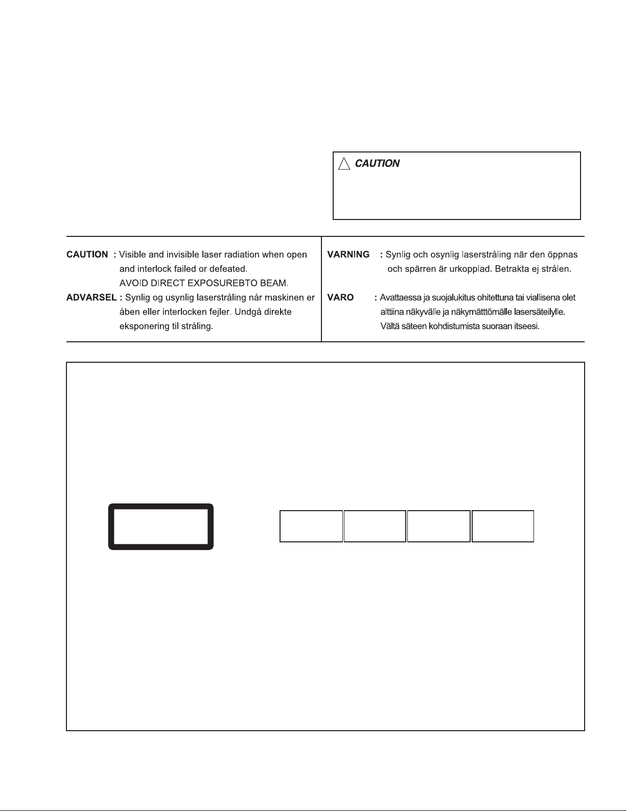
REPRODUCTION AND POSITION OF LABELS
WARNING LABEL
CAUTION : Visible and Invisible
CLASS 1
LASER PRODUCT
laser radiation when open and
interlock failed or defeated.
AVOID DIRECT EXPOSURE TO
BEAM. (e)
ADVARSEL : Synlig og usynlig
laserstråling når maskinen er
åben eller interlocken fejeler.
Undgå direkte eksponering til
stråling. (d)
VARNING : Synlig och
osynling laserstrålning när
den öppnas och spärren är
urkopplad. Betrakta ej
strålen. (s)
VARO : Avattaessa ja suojalukitus
ohitettuna tai viallisena olet alttiina
näkyvälle ja näkymättömälle
lasersäteilylle. Vältä säteen
kohdistumista suoraan itseesi. (f)
(No.MA143)1-5
Page 6

SECTION 2
SPECIFIC SERVICE INSTRUCTIONS
This service manual does not describe SPECIFIC SERVICE INSTRUCTIONS.
1-6 (No.MA143)
Page 7
SECTION 3
DISASSEMBLY
3.1 Main body section
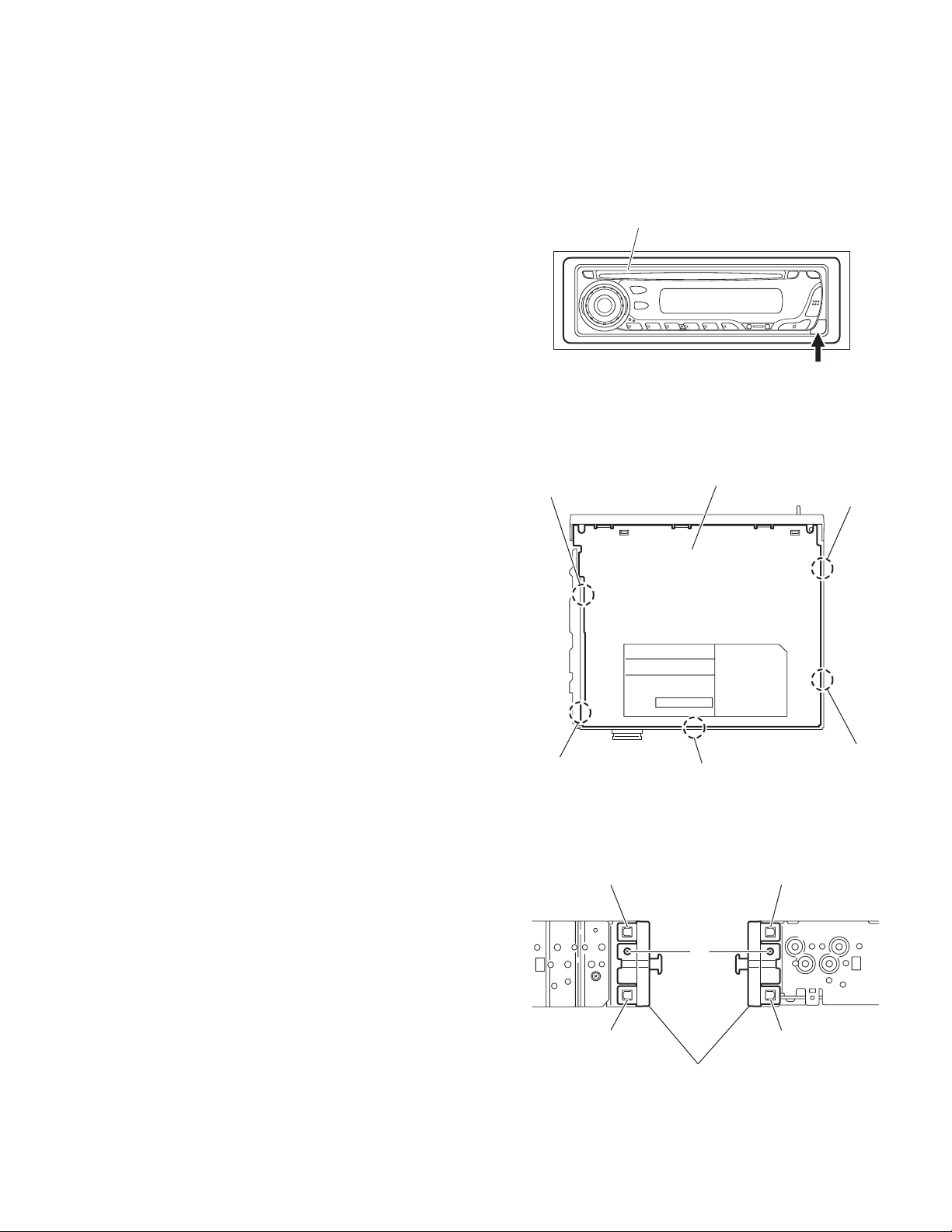
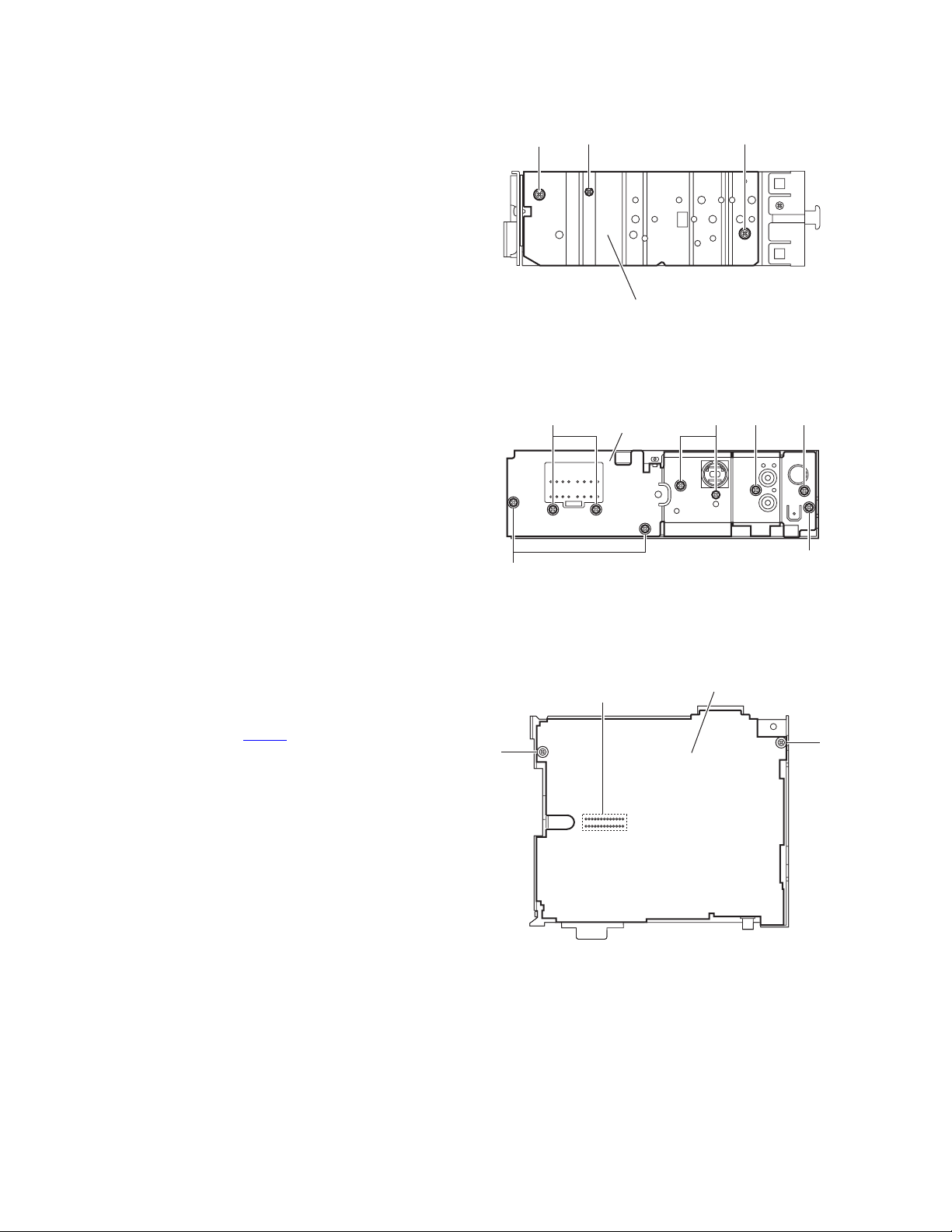
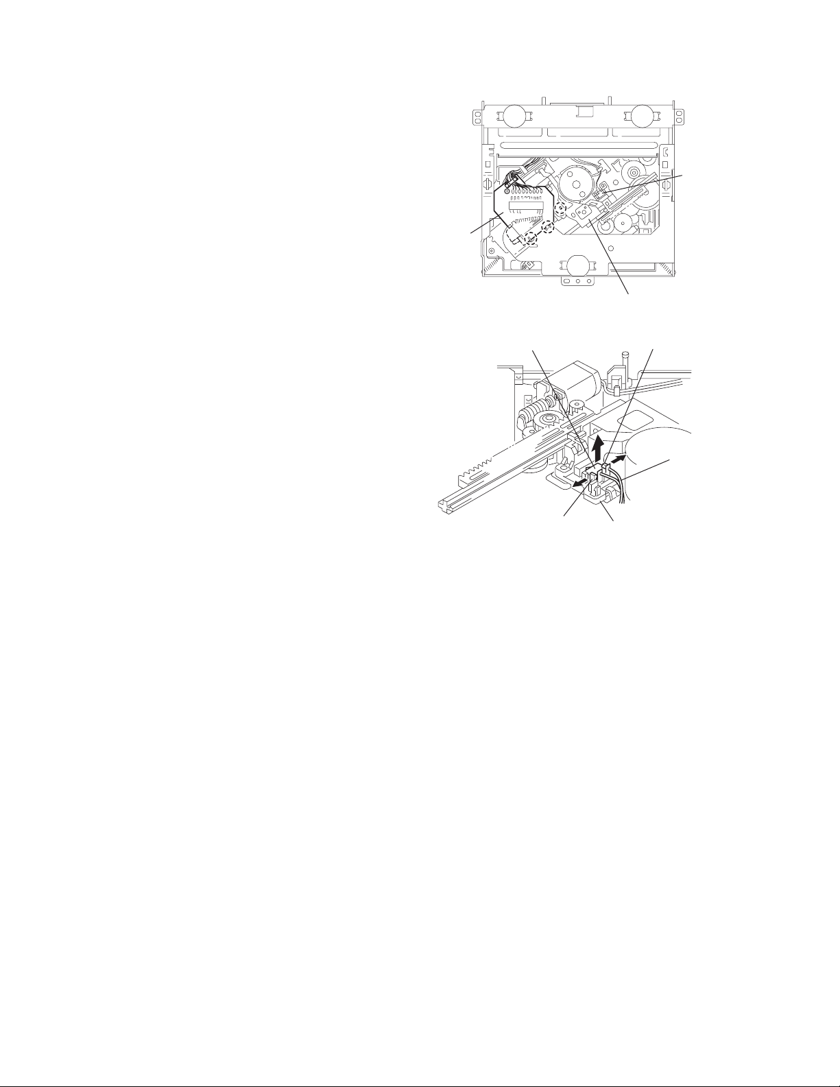
3.1.1 Removing the front panel assembly
(See Fig.1)
(1) Push the detach button in the lower right part of the front
panel assembly and remove the front panel assembly.
3.1.2 Removing the bottom cover
(See Fig.2)
(1) Turn the main body up side down.
(2) Insert a screwdriver under the joints to release the two
joints a on the left side, two joints b on the right side and
joint c on the back side of the main body, then remove the
bottom cover from the main body.
Note:
When releasing the joints using a screwdriver, do not damage
the main board.
Joint a
Front panel assembly
Detach button
Fig.1
Bottom cover
Joint b
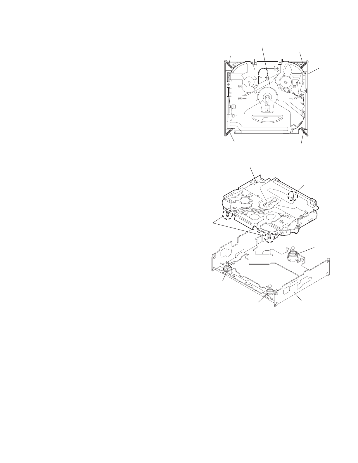
3.1.3 Removing the front chassis assembly
(See Fig.3)
• Prior to performing the following procedures, remove the front
panel assembly and bottom cover.
(1) Remove the two screws A on the both sides of the main
body.
(2) Release the two joints d and two joints e on the both sides
of the main body, then remove the front chassis assembly
toward the front.
Joint a
Joint c
Fig.2
Joint d Joint e
A
Joint d
Front chassis assembly
Fig.3
Joint e
Joint b
(No.MA143)1-7
Page 8
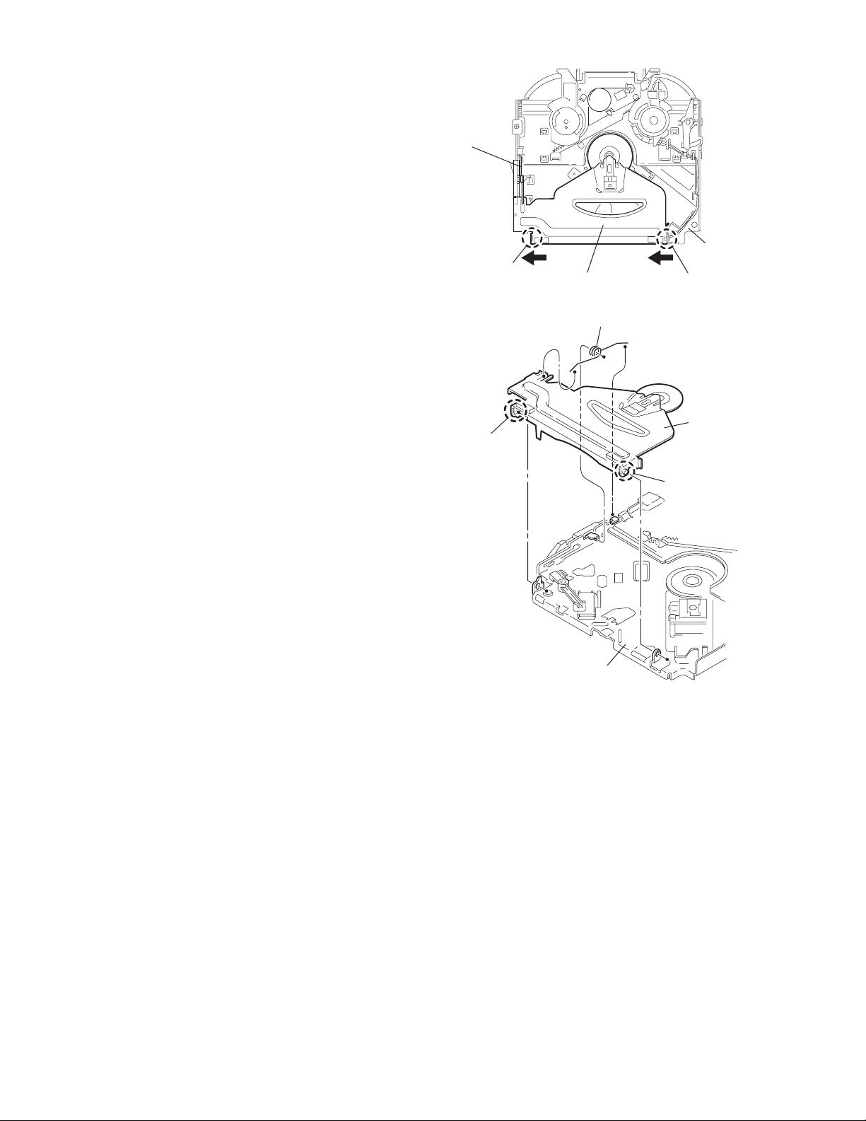
3.1.4 Removing the side panel
(See Fig.4)
• Prior to performing the following procedure, remove the front
panel assembly as required.
(1) Remove the screw B and two screws C attaching the side
panel on the left side of the main body, and take out the
side panel.
3.1.5 Removing the rear bracket
(See Fig.5)
• Prior to performing the following procedure, remove the bottom
cover.
(1) Remove the three screws D, three screws E and three
screws F attaching the rear bracket on the back side of the
main body.
(2) Take out the rear bracket.
F
C
E
C
B
Side panel
Fig.4
EF
Rear bracket
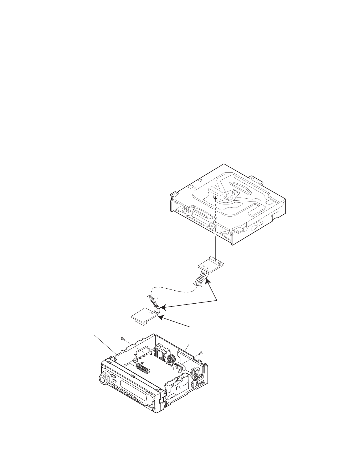
3.1.6 Removing the main board
(See Fig.6)
• Prior to performing the following procedures, remove the front
panel assembly, bottom cover, front chassis assembly, side
panel and rear bracket.
(1) Remove the two screws G attaching the main board.
(2) Disconnect the connector CN501
the main body and take out the main board.
on the main board from
G
D
D
Fig.5
Main board
CN501
G
Fig.6
1-8 (No.MA143)
Page 9
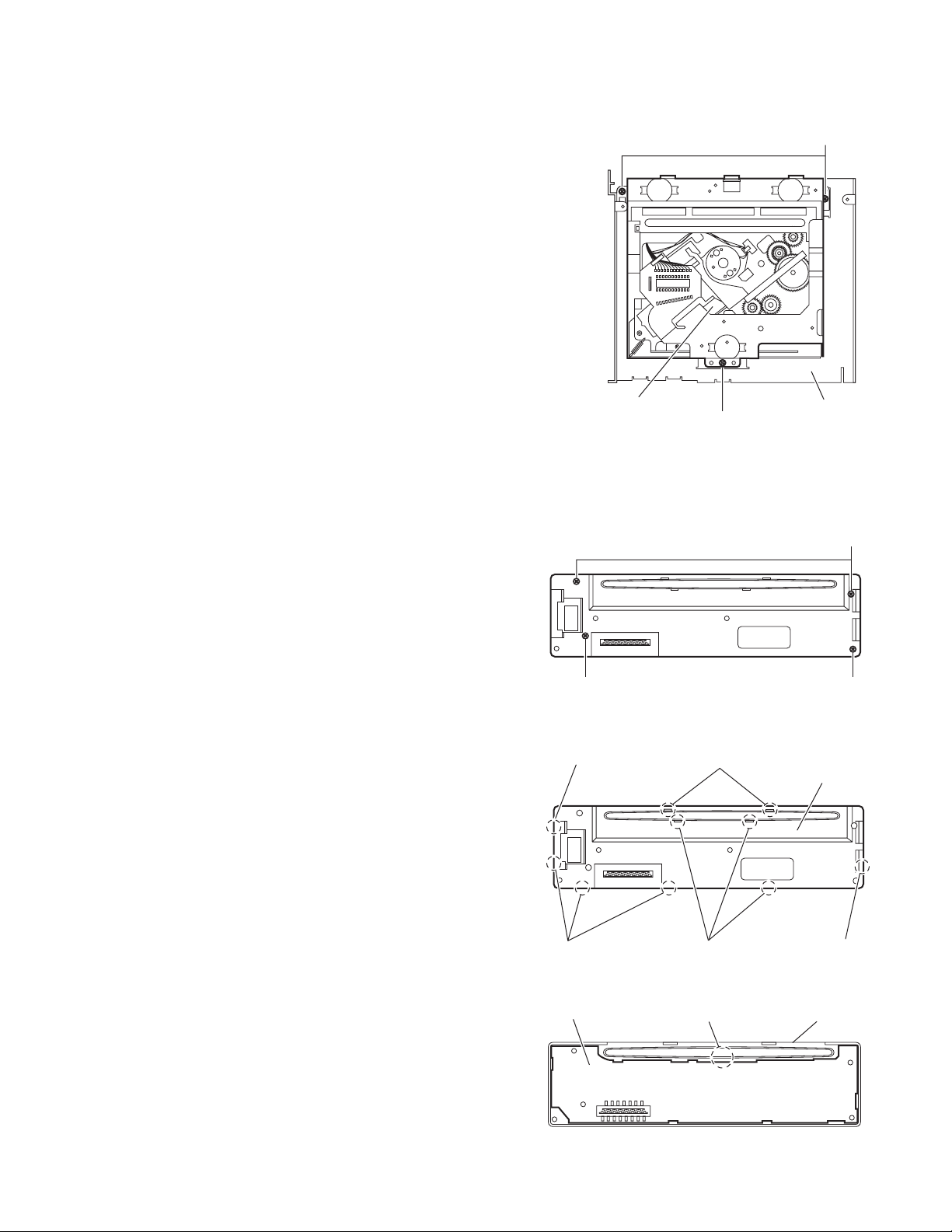
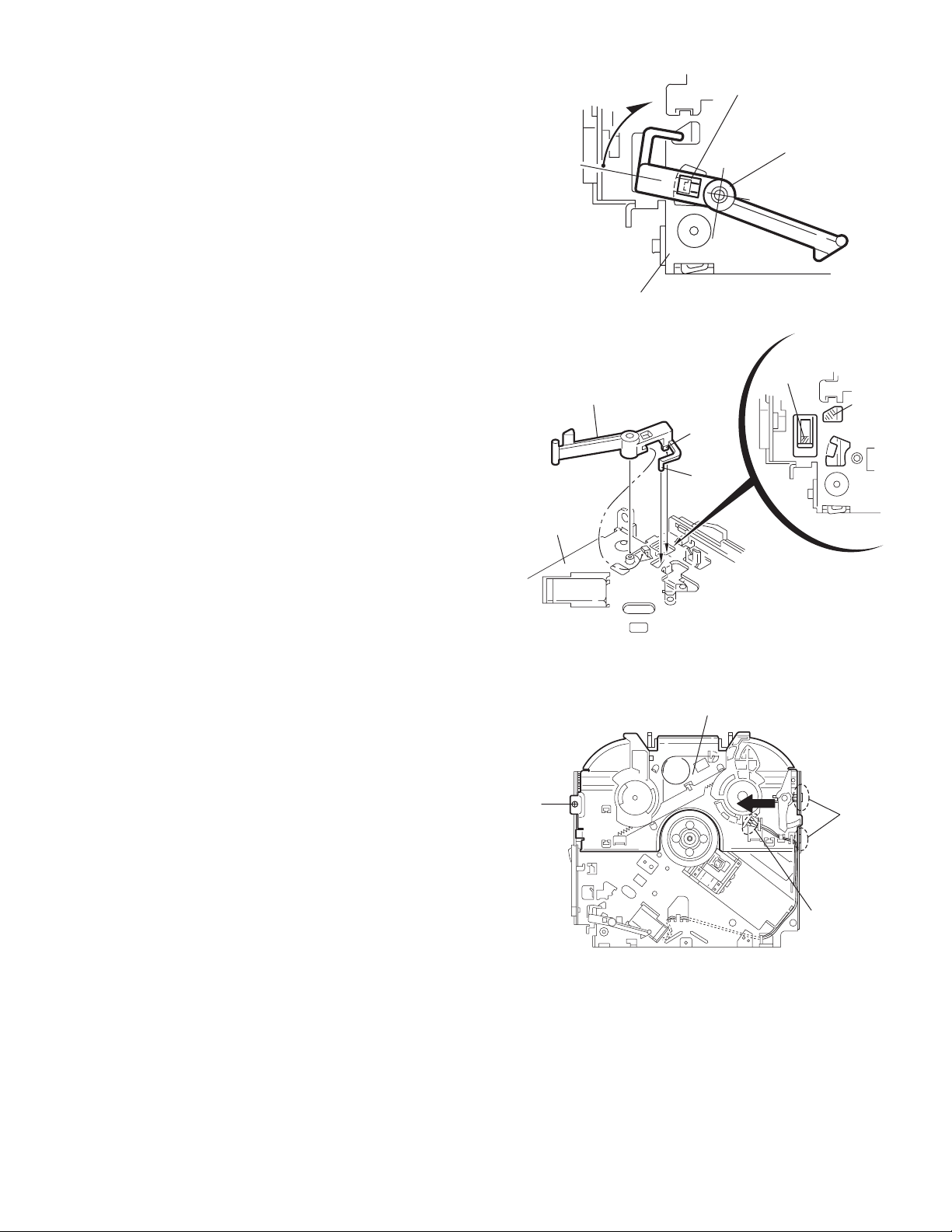
3.1.7 Removing the CD mechanism assembly
(See Fig. 7)
• Prior to performing the following procedure, remove the front
panel assembly, bottom cover, side panel, rear bracket and
main board.
• Remove the front chassis assembly as required.
(1) Remove the three screws H attaching the CD mechanism
assembly on the top chassis.
(2) Take out the CD mechanism assembly.
H
3.1.8 Removing the switch board
(See Figs.8 to 10)
• Prior to performing the following procedures, remove the front
panel assembly.
(1) Remove the four screws J on the back side of the front pan-
el assembly. (See Fig.8)
(2) Release the ten joints f and remove the rear cover. (See
Fig.9)
(3) Release the joint g and take out the switch board from the
front panel assembly. (See Fig.10)
CD mechanism assembly
J
Joint f
Top chassis
H
Fig.7
J
J
Fig.8
Joints f
Rear cover
Joints f
Switch board
Joints f
Fig.9
Joint g
Fig.10
Joint f
Front panel assembly
(No.MA143)1-9
Page 10
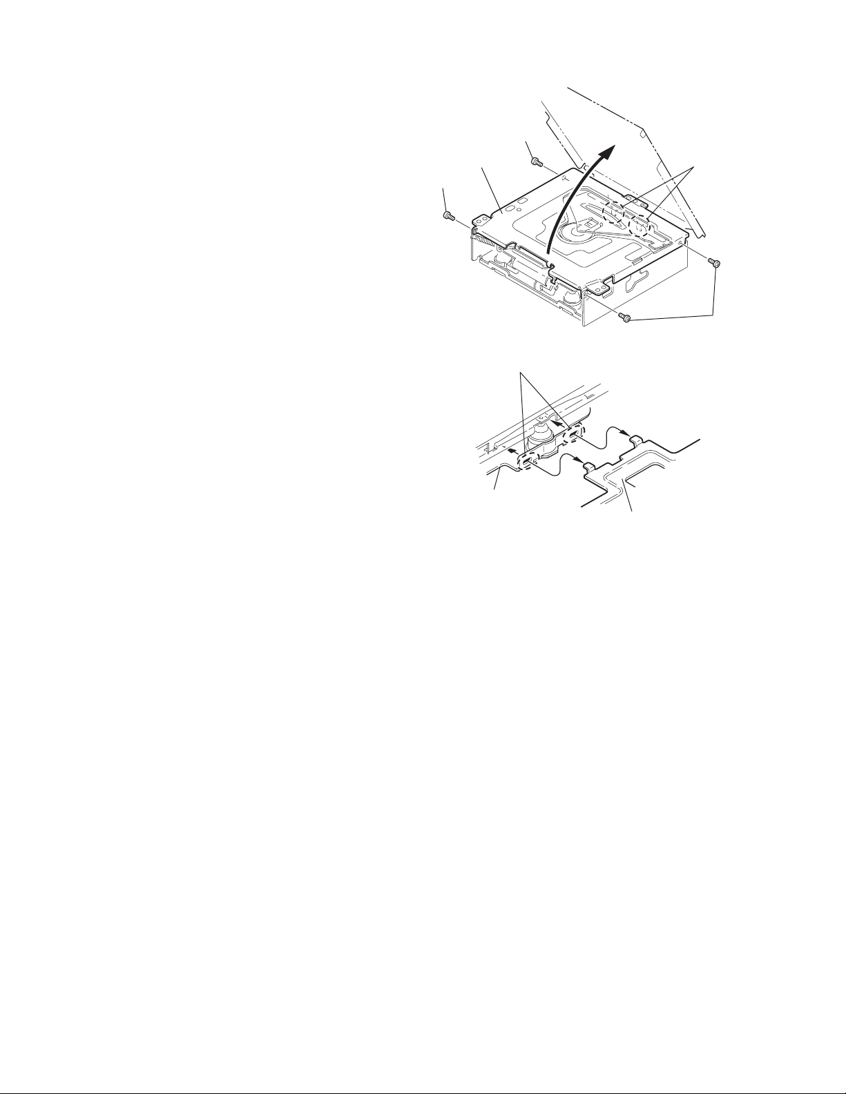
3.2 CD Mechanism Assembly
A
3.2.1 Removing the top cover
(See Figs.1 and 2)
(1) Remove the two screws A on the both side of the body.
(2) Lift the front side of the top cover and move the top cover
backward to release the two joints a.
Top cover
Joints a
A
Joints a
A
Fig.1
Fig.2
Top cover
1-10 (No.MA143)
Page 11
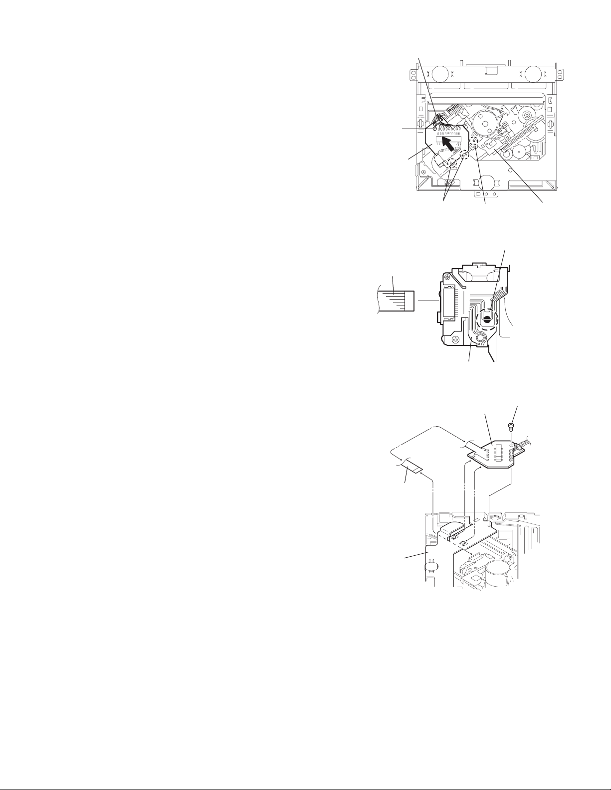
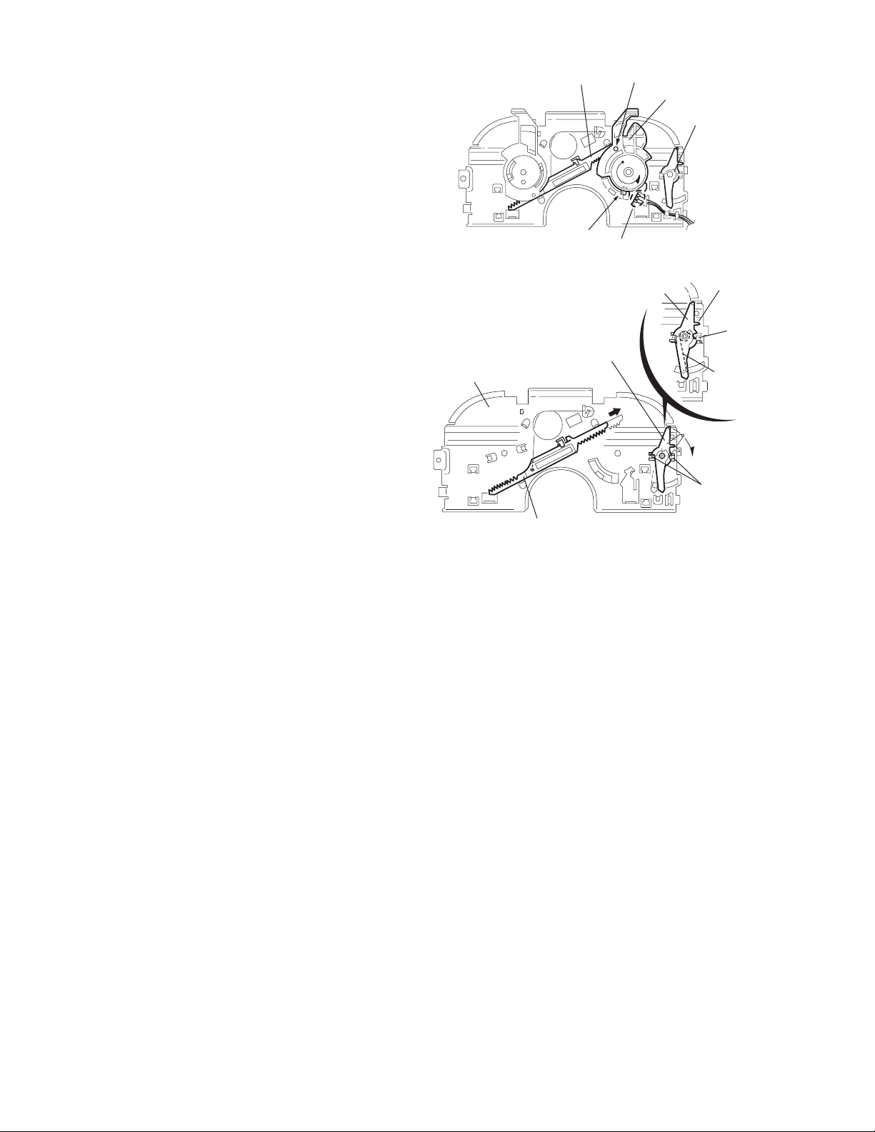
3.2.2 Removing the connector board
(See Figs.3 to 5)
CAUTION:
Before disconnecting the flexible wire from the pickup, solder
the short-circuit point on the pickup. No observance of this in-
struction may cause damage of the pickup.
(1) Remove the screw B fixing the connector board.
(2) Solder the short-circuit point on the connector board.
(3) Disconnect the flexible wire from the pickup.
(4) Move the connector board in the direction of the arrow to
release the two joints b.
(5) Unsolder the wire on the connector board if necessary.
CAUTION:
Unsolder the short-circuit point after reassembling.
B
Connector board
Flexible wire
Wires
Joints b
Short-circuit point
Fig.3
Short-circuit point
(Soldering)
Pickup
Flexible wire
Frame
Pickup
Fig.4
B
Connector board
Fig.5
(No.MA143)1-11
Page 12
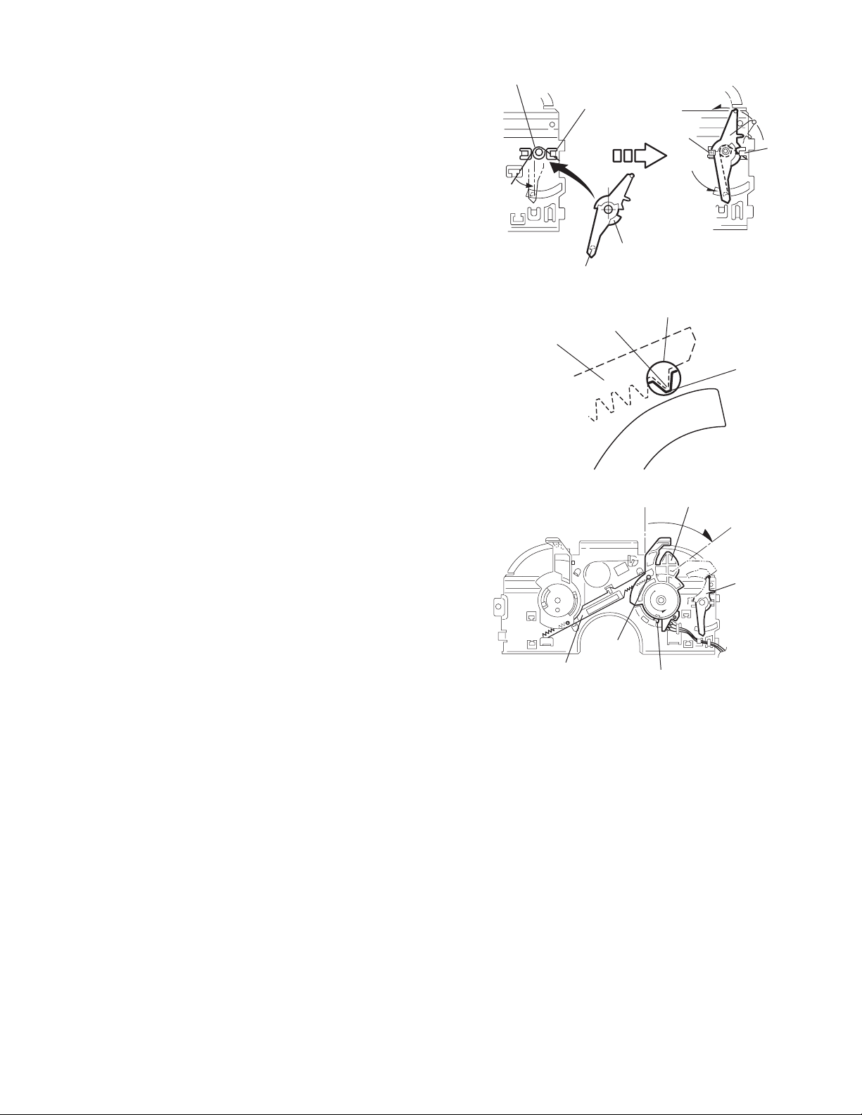
3.2.3 Removing the DET switch
(See Figs.6 and 7)
(1) Extend the two tabs c of the feed sw. holder and pull out
the switch.
(2) Unsolder the DET switch wire if necessary.
Connector
board
DET switch
DET switch
Pickup
Fig.6
Tab c
DET switch wire
Tab c
Feed sw. holder
Fig.7
1-12 (No.MA143)
Page 13
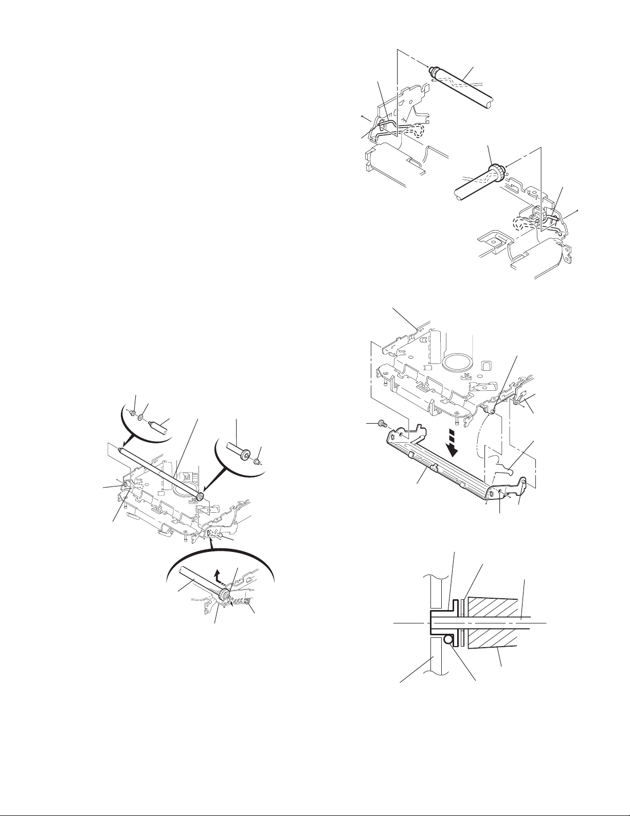
3.2.4 Removing the chassis unit
r
(See Figs.8 and 9)
• Prior to performing the following procedure, remove the top
cover and connector board.
(1) Remove the two suspension springs (L) and (R) attaching
the chassis unit to the frame.
CAUTION:
• The shape of the suspension spring (L) and (R) are different. Handle them with care.
• When reassembling, make sure that the three shafts
on the underside of the chassis unit are inserted to the
dampers certainly.
Suspension spring (R)
Chassis unit
Suspension spring (L)
Frame
Suspension spring (R)
Chassis unit
Shafts
Damper
Damper
Suspension spring (L)
Fig.8
Shaft
Dampe
Frame
Fig.9
(No.MA143)1-13
Page 14
3.2.5 Removing the clamper assembly
(See Figs.10 and 11)
• Prior to performing the following procedure, remove the top
cover.
(1) Remove the clamper arm spring.
(2) Move the clamper assembly in the direction of the arrow to
release the two joints d.
Clamper arm
spring
Joint d
Joint d
Clamper assembly
Fig.10
Clamper arm spring
Chassis rivet
assembly
Joint d
Clamper
assembly
Chassis rivet assembly
Fig.11
Joint d
1-14 (No.MA143)
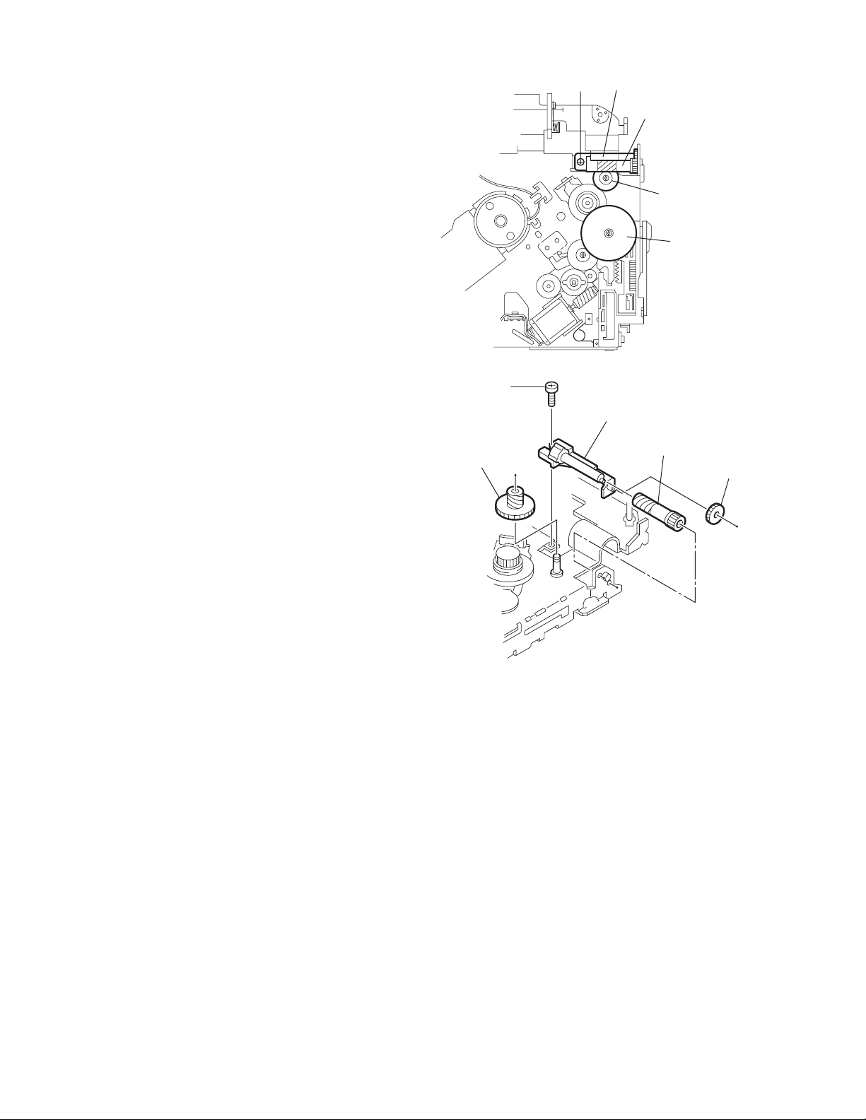
Page 15

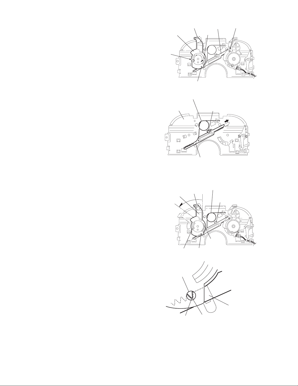
3.2.6 Removing the loading / feed motor assembly
(See Figs.12 and 13)
• Prior to performing the following procedure, remove the top
cover, connector board and chassis unit.
(1) Remove the screw C and move the loading / feed motor
assembly in the direction of the arrow to remove it from the
chassis rivet assembly.
(2) Disconnect the wire from the loading / feed motor assembly
if necessary.
CAUTION:
When reassembling, connect the wire from the loading /
feed motor assembly to the flame as shown in Fig.12.
Loading / feed motor assembly
Fig.12
Loading / feed motor assembly
C
Fig.13
(No.MA143)1-15
Page 16
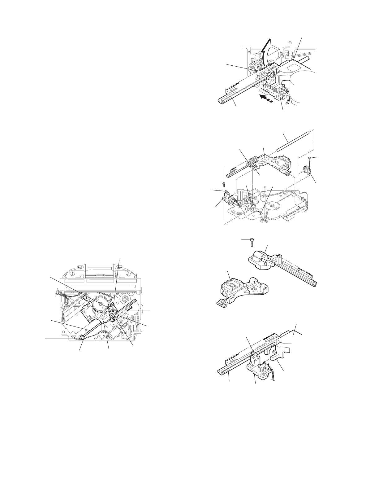
3.2.7 Removing the pickup unit
(See Figs.14 to 18)
• Prior to performing the following procedure, remove the top
cover, connector board and chassis unit.
(1) Remove the screw D and pull out the pu. shaft holder from
the pu. shaft.
(2) Remove the screw E attaching the feed sw. holder.
(3) Move the part e of the pickup unit upward with the pu. shaft
and the feed sw. holder, then release the joint f of the feed
sw. holder in the direction of the arrow. The joint g of the
pickup unit and the feed rack is released, and the feed sw.
holder comes off.
(4) Remove the pu. shaft from the pickup unit.
(5) Remove the screw F attaching the feed rack to the pickup
unit.
3.2.8 Reattaching the pickup unit
(See Figs.14 to 17)
(1) Reattach the feed rack to the pickup unit using the screw F.
(2) Reattach the feed sw. holder to the feed rack while setting
the joint g to the slot of the feed rack and setting the part f
of the feed rack to the switch of the feed sw. holder correctly.
(3) As the feed sw. holder is temporarily attached to the pickup
unit, set to the gear of the joint g and to the bending part of
the chassis (joint h) at a time.
CAUTION:
Make sure that the part i on the underside of the feed
rack is certainly inserted to the slot j of the change lock
lever.
(4) Reattach the feed sw. holder using the screw E.
(5) Reattach the pu. shaft to the pickup unit. Reattach the pu.
shaft holder to the pu. shaft using the screw D.
Feed sw. holder
Joint f
Joint g
Feed sw.
holder
Part e
Feed rack
Part i
E
Pickup unit
Slot j
F
Fig.15
Pu. shaft
Pickup unit
Joint f
Joint h
Fig.16
Feed rack
Pickup unit
Feed sw. holder
D
Pu. shaft
holder
Pu. shaft
D
Pu. shaft holder
1-16 (No.MA143)
Pickup unit
Fig.14
Part e
E
Joint g
Feed rack
Fig.17
Pickup unit
Joint g
Joint f
Feed sw. holder
Fig.18
Page 17
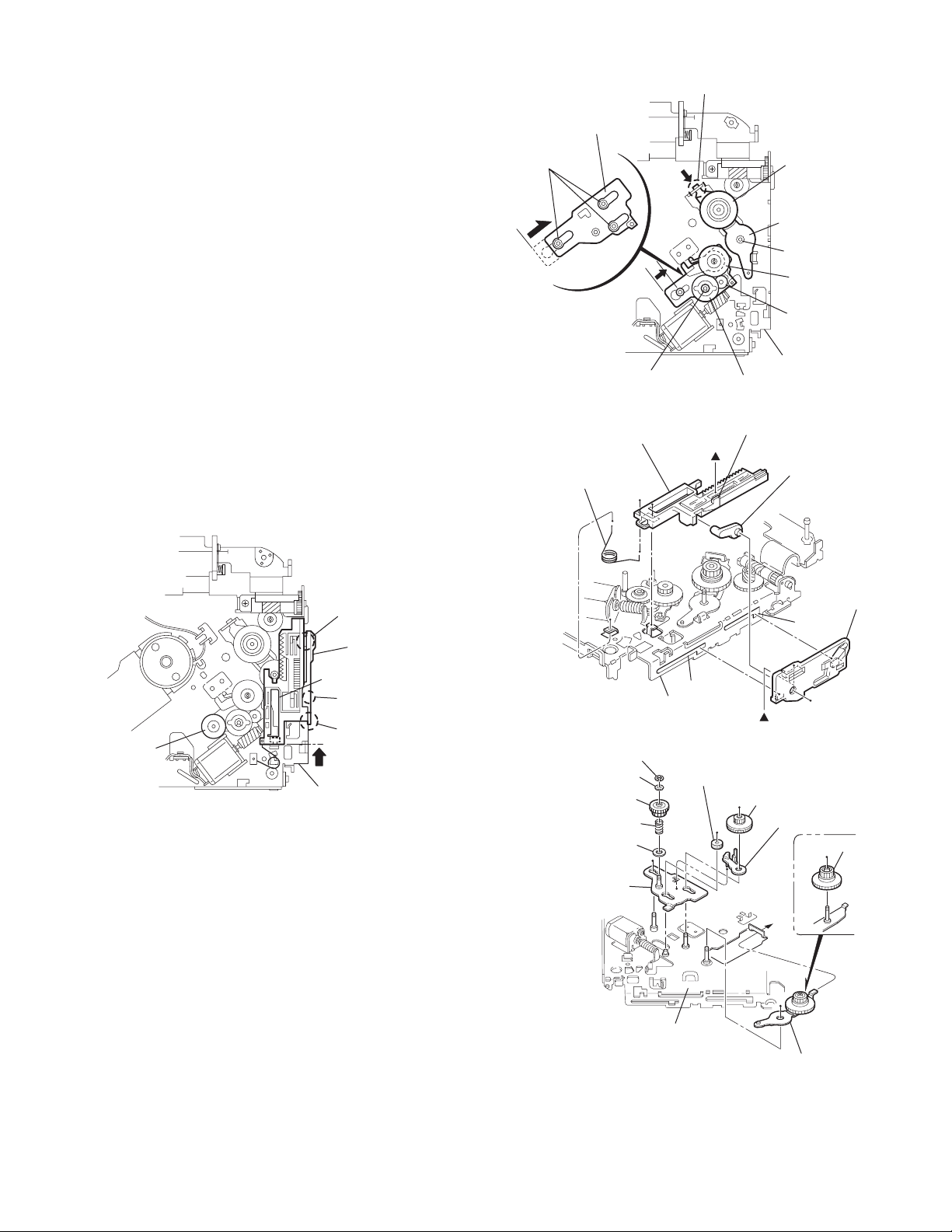
3.2.9 Removing the trigger arm
r
(See Figs.19 and 20)
• Prior to performing the following procedure, remove the top
cover, connector board and clamper unit.
(1) Turn the trigger arm in the direction of the arrow to release
the joint k and pull out upward.
CAUTION:
When reassembling, insert the part m and n of the trigger
arm into the part p and q at the slot of the chassis rivet
assembly respectively and join the joint k at a time.
Chassis rivet assembly
Trigger arm
Chassis rivet
assembly
Joint k
Trigger arm
Fig.19
Part p
Part q
Part m
Part n
3.2.10 Removing the top plate assembly
(See Fig.21)
• Prior to performing the following procedure, remove the top
cover, connector board, chassis unit, and clamper assembly.
(1) Remove the screw H.
(2) Move the top plate assembly in the direction of the arrow to
release the two joints r.
(3) Unsolder the wire marked s if necessary.
H
Fig.20
Top plate assembly
Joints
s
Fig.21
(No.MA143)1-17
Page 18
3.2.11 Removing the mode sw. / select lock arm
(See Figs.22 and 23)
• Prior to performing the following procedure, remove the top
plate assembly.
(1) Bring up the mode sw. to release from the link plate (joint t)
and turn in the direction of the arrow to release the joint u.
(2) Unsolder the wire of the mode sw. marked s if necessary.
(3) Turn the select lock arm in the direction of the arrow to re-
lease the two joints v.
(4) The select lock arm spring comes off the select lock arm at
the same time.
Top plate
Link plate
Joint u
Joint t
s
Fig.22
Select lock arm
Select lock arm
Mode sw.
Select lock arm
Top plate
Hook w
Select lock
arm spring
Link plate
Joints v
Fig.23
1-18 (No.MA143)
Page 19
3.2.12 Reassembling the mode sw. / select lock arm
(See Figs.24 to 26)
REFERENCE:
Reverse the above removing procedure.
(1) Reattach the select lock arm spring to the top plate and set
the shorter end of the select lock arm spring to the hook w
on the top plate.
(2) Set the other longer end of the select lock arm spring to the
boss x on the underside of the select lock arm, and join the
select lock arm to the slots (joint v). Turn the select lock
arm as shown in the figure.
(3) Reattach the mode sw. while setting the part t to the first
peak of the link plate gear, and join the joint u.
CAUTION:
When reattaching the mode sw., check if the points y and
z are correctly fitted and if each part operates properly.
Select lock arm spring
Hook w
Joint v
Joint v
Select lock arm
Boss x
Fig.24
Joint t
Point y
Link plate
Point z
Link plate
Fig.25
Mode sw.
Select
lock arm
Joint t
Joint u
Fig.26
(No.MA143)1-19
Page 20
3.2.13 Removing the select arm R / link plate
(See Figs.27 and 28)
• Prior to performing the following procedure, remove the top
plate assembly.
(1) Bring up the select arm R to release from the link plate
(joint a') and turn as shown in the figure to release the two
joints b' and joint c'.
(2) Move the link plate in the direction of the arrow to release
the joint d'. Remove the link plate spring at the same time.
REFERENCE:
Before removing the link plate, remove the mode sw..
Select arm R
Joint b'
Link plate spring
Joint c'
Joint a'
Link plate
Joint b'
Fig.27
Joint r
3.2.14 Reattaching the Select arm R / link plate
(See Figs.29 and 30)
REFERENCE:
Reverse the above removing procedure.
(1) Reattach the link plate spring.
(2) Reattach the link plate to the link plate spring while joining
them at joint d'.
(3) Reattach the joint a' of the select arm R to the first peak of
the link plate while joining the two joints b' with the slots.
Then turn the select arm R as shown in the figure. The top
plate is joined to the joint c'.
CAUTION:
When reattaching the select arm R, check if the points e'
and f' are correctly fitted and if each part operates properly.
Top plate
Select arm R
Joint b'
Joint d'
Link plate
Fig.28
Link plate spring
Joint c'
Joint d'
Joint b'
Joint a'
Fig.29
1-20 (No.MA143)
Joint a'
Point e'
Link plate
Point f'
Fig.30
Page 21
3.2.15 Removing the loading roller assembly
(See Figs.31 to 33)
• Prior to performing the following procedure, remove the
clamper assembly and top plate assembly.
(1) Push inward the loading roller assembly on the gear side
and detach it upward from the slot of the joint g' of the lock
arm rivet assembly.
(2) Detach the loading roller assembly from the slot of the joint
h' of the lock arm rivet assembly.
Roller guide
spring
Part k'
Loading roller assembly
Loading roller assembly
The roller guide comes off the gear section of the loading
roller assembly.
Remove the roller guide and the HL washer from the shaft
of the loading roller assembly.
(3) Remove the screw J attaching the lock arm rivet assembly.
(4) Push the shaft at the joint i' of the lock arm rivet assembly
inward to release the lock arm rivet assembly from the slot
of the L side plate.
(5) Extend the lock arm rivet assembly outward and release
the joint j' from the boss of the chassis rivet assembly. The
roller guide springs on both sides come off at the same
time.
CAUTION:
When reassembling, reattach the left and right roller
guide springs to the lock arm rivet assembly before reattaching the lock arm rivet assembly to the chassis rivet
assembly. Make sure to fit the part k' of the roller guide
spring inside of the roller guide. (Refer to Fig.34.)
Roller guide
HL washer
Loading roller assembly
Roller guide
Chassis rivet assembly
J
Roller guide
spring
Fig.32
Boss
L side plate
Roller guide spring
Joint h'
Roller guide spring
Loading roller assembly
Joint g'
Lock arm rivet assembly
Fig.31
Roller guide spring
Roller guide spring
Lock arm rivet assembly
Lock arm rivet assembly
Joint i'
Part j'
Fig.33
Roller guide
HL washer
Roller shaft assembly
Loading roller
Roller guide spring
Fig.34
(No.MA143)1-21
Page 22
3.2.16 Removing the loading gear 5, 6 and 7
(See Figs.35 and 36)
• Prior to performing the following procedure, remove the top
cover, chassis unit, pickup unit and top plate assembly.
(1) Remove the screw K attaching the loading gear bracket.
The loading gear 6 and 7 come off the loading gear bracket.
(2) Pull out the loading gear 5.
K
Loading gear bracket
K
Loading gear 6
Loading gear 5
Loading gear 3
Fig.35
Loading gear bracket
Loading gear 5
Loading gear 6
Loading gear 7
Fig.36
1-22 (No.MA143)
Page 23
3.2.17 Removing the gears
(See Figs.37 to 40)
• Prior to performing the following procedure, remove the top
cover, chassis unit, top plate assembly and pickup unit.
• Pull out the loading gear 3. (See Fig.35.)
(1) Pull out the feed gear.
(2) Move the loading plate assembly in the direction of the ar-
row to release the L side plate from the two slots m' of the
chassis rivet assembly. (See Fig.37.)
(3) Detach the loading plate assembly upward from the chas-
sis rivet assembly while releasing the joint n'. Remove the
slide hook and loading plate spring from the loading plate
assembly.
(4) Pull out the loading gear 2 and remove the change lock le-
ver.
(5) Remove the E ring and washer attaching the changer gear
2.
(6) The changer gear 2, change gear spring and adjusting
washer come off.
(7) Remove the loading gear 1.
(8) Move the change plate rivet assembly in the direction of the
arrow to release from the three shafts of the chassis rivet
assembly upward. (See Fig.38.)
(9) Detach the loading gear plate rivet assembly from the shaft
of the chassis rivet assembly upward while releasing the
joint p'. (See Figs.38 and 40.)
(10) Pull out the loading gear 4.
Change plate
rivet assembly
Shafts
E ring
Loading plate assembly
Loading plate spring
Joint p'
Loading gear 4
Loading gear plate
rivet assembly
Shaft
Loading gear 2
Loading gear 1
Chassis rivet assembly
Change gear 2
Fig.38
Joint n'
Slide hook
Feed gear
Fig.37
Slot m'
L side plate
Loading plate assembly
Joint n'
Slot m'
Chassis rivet assembly
Chassis rivet assembly
E ring
Washer
Change gear 2
Change gear spring
Adjusting washer
Change plate
rivet assembly
Chassis rivet assembly
L side plate
Slot m'
Slot m'
Fig.39
Loading gear 1
Loading gear 2
Change lock lever
Loading gear 4
Loading gear plate rivet assembly
Fig.40
(No.MA143)1-23
Page 24
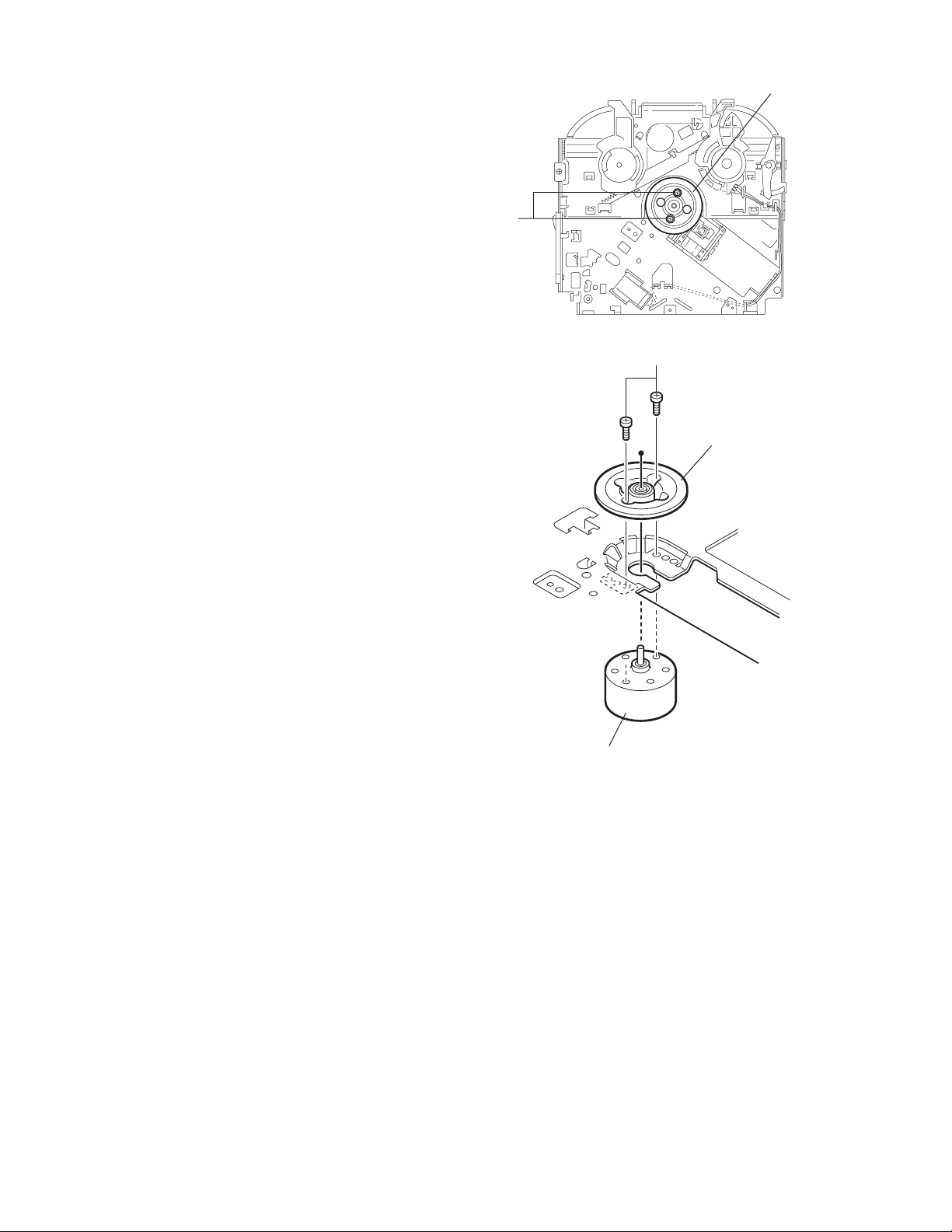
3.2.18 Removing the turn table / spindle motor
(See Figs.41 and 42)
• Prior to performing the following procedure, remove the top
cover, connector board, chassis unit and clamper assembly.
(1) Remove the two screws L attaching the spindle motor as-
sembly through the slot of the turn table on top of the body.
(2) Unsolder the wire on the connector board if necessary.
Turn table
L
Fig.41
L
Turn table
1-24 (No.MA143)
Spindle motor
Fig.42
Page 25
SECTION 4
ADJUSTMENT
4.1 Adjustment method
Test instruments required for adjustment
(1) Digital oscilloscope (100MHz)
(2) Electric voltmeter
(3) Digital tester
(4) Tracking offset meter
(5) Test Disc JVC :CTS-1000
(6) Extension cable for check
EXTSH002-22P × 1
Standard volume position
Balance and Bass &Treble volume : lndication"0"
Loudness : OFF
How to connect the extension cable for adjusting
Caution:
Be sure to attach the heat sink and rear bracket onto the power amplifier IC and regulator IC respectively, before supply the power.
If voltage is applied without attaching these parts, the power amplifier IC and regulator IC will be destroyed by heat.
Standard measuring conditions
Power supply voltage DC14.4V(11 to 16V)
Load impedance 20KΩ(2 Speakers connection)
Output Level Line out 2.0V (Vol. MAX)
Dummy load
Exclusive dummy load should be used for AM,and FM. For FM
dummy load,there is a loss of 6dB between SSG output and
antenna input.The loss of 6dB need not be considered since
direct reading of figures are applied in this working standard.
Heat sink
Extension cable
EXTSH002-22P
Rear bracket
(No.MA143)1-25
Page 26
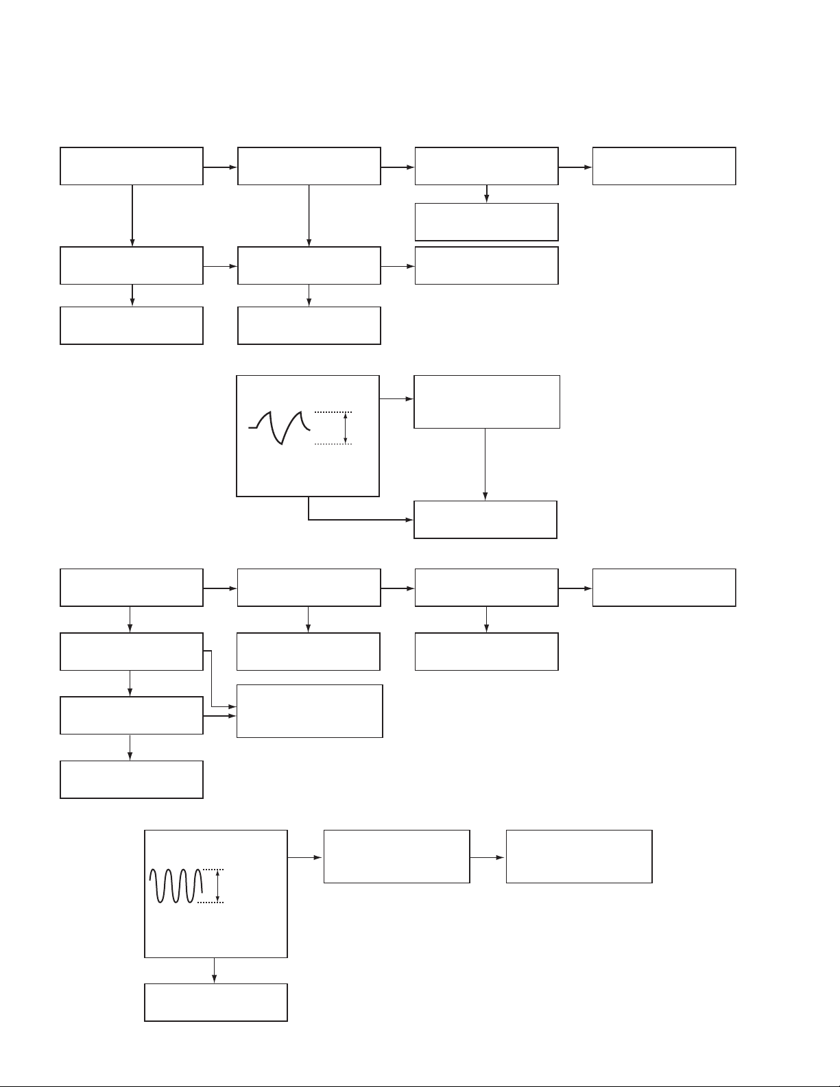
5.1 Feed section
SECTION 5
TROUBLESHOOTING
Is 5v or 0V at IC541
pin 40?
YES
Is 4V present at both
sides of the feed motor?
YES
Check the feed motor.
5.2 Focus section
5.3 Spindle section
NO
Is the wiring for IC541
pin 40 correct?
NO
Is 6V or 2V present at
IC501 pins 4 and 5?
Check IC501.
When the lens is
moving:
Does the S-search
waveform appear at
IC501 pins 8 and 9?
NO
NO
YES
4V
YES
YES
Is 5V present at IC501
pin 20?
Check the vicinity of
IC541.
Check the feed motor
connection wiring.
NO
Check the circuits in
the vicinity of IC501
pins 15 and 16.
Check the pickup and
its connections.
NO
Check CD8V.
YES
YES
Is the disk rotated?
YES
Does the RF signal
appear at RF test point?
YES
Is the RF waveform
at RF test point distorted?
YES
Proceed to the Tracking
section
5.4 Tracking section
When the disc is rotated
at first:
Is the tracking error
signal output at IC521
pin 11?
NO
Is 4V present between
IC501 pins 6 and 7?
Check the spindle motor
and its wiring.
NO
Check the circuits in
the vicinity of IC521 pins
2 to 12 or the pickup.
NO
NO
Approx. 1.2V
YES
NO
YES
Check the circuits in
the vicinity of IC521
pins 2 to 12.
Is 4V present at IC541
pin 41?
YES
Check the vicinity of
IC501.
NO
Check the pickup and
its connections.
NO
Check IC541.
1-26 (No.MA143)
Check IC541.
Page 27

5.5 Signal processing section
Is the sound output from
both channels (L, R)?
YES
Normal
NO
No sound from either
channel.
Is 9V present at IC161
pin 31?
Is the audio signal
(including sampling
output components)
output to IC581 pins 1
and 7 during playback?
Is the audio signal
output at IC161 pins 3
and 30 during playback?
YES
YES
YES
Compare the L-ch and
NO
R-ch to locate the
defective point.
NO
Is 9V present at IC901
pin 13?
Check the connection
between IC901 pin13
and IC161 pin31.
NO
Check IC581 and its
peripheral circuits.
NO
Check IC161 and its
peripheral circuits.
YES
NO
Check IC901 and its
peripheral circuits.
YES
Check the power amp.
IC301.
(No.MA143)1-27
Page 28
5.6 Maintenance of laser pickup
(1) Cleaning the pick up lens
Before you replace the pick up, please try to clean the lens
with a alcohol soaked cotton swab.
(2) Life of the laser diode
When the life of the laser diode has expired, the following
symptoms will appear.
• The level of RF output (EFM output: amplitude of eye
pattern) will be low.
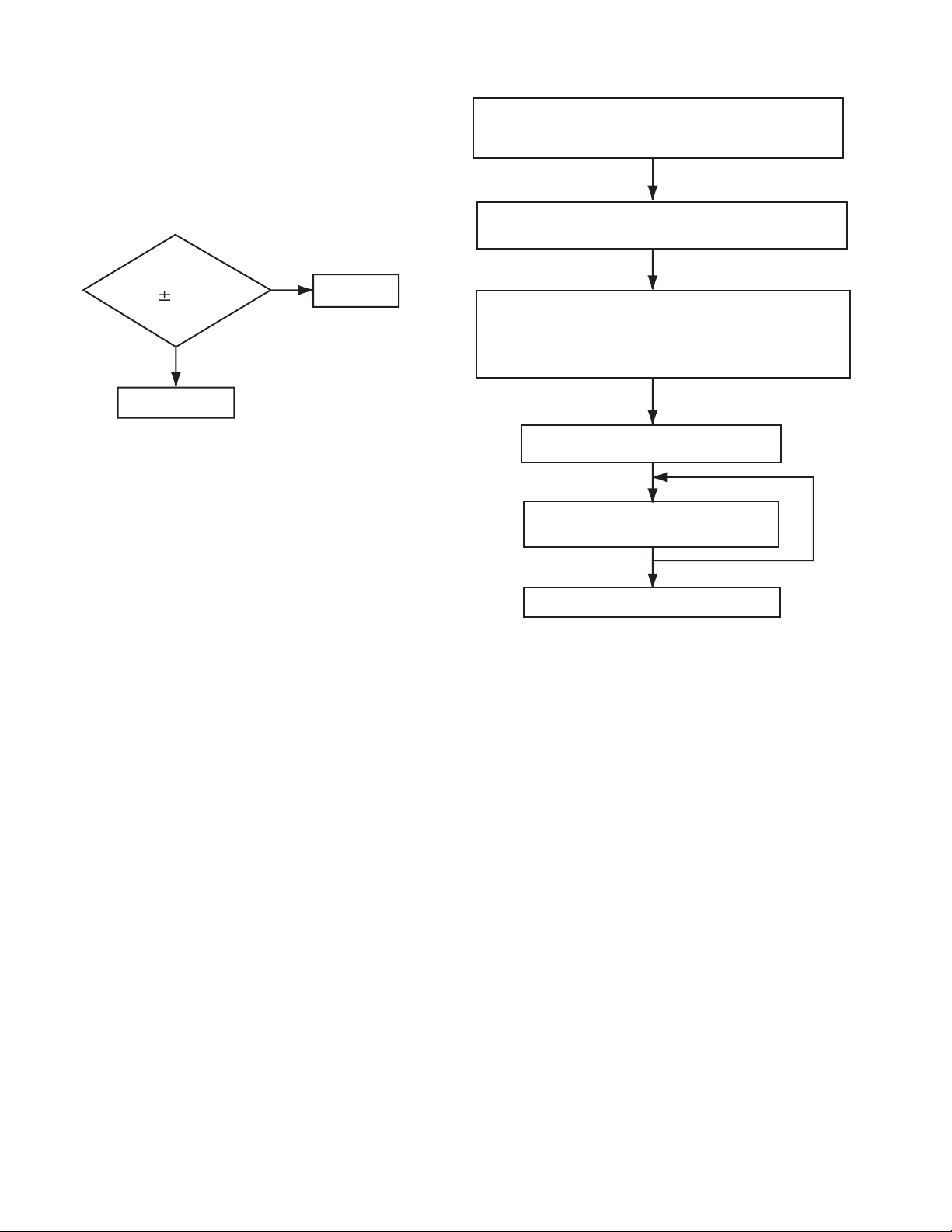
5.7 Replacement of laser pickup
Turn of the power switch and, disconnect the
power cord.
Replace the pickup with a normal one. (Refer
to "Removing the pickup unit" on the previous page.)
Is RF output
1.3 0.4Vp-p?
NO
Replace it.
YES
OK
(3) Semi-fixed resistor on the APC PC board
The semi-fixed resistor on the APC printed circuit board
which is attached to the pickup is used to adjust the laser
power.Since this adjustment should be performed to match
the characteristics of the whole optical block, do not touch
the semi-fixed resistor.
If the laser power is lower than the specified value, the laser diode is almost worn out, and the laser pickup should
be replaced. If the semi-fixed resistor is adjusted while the
pickup is functioning normally, the laser pickup may be
damaged due to excessive current.
Plug the power cord in, and turn the power on.
At this time, check that the laser emits for about
seconds and the objective lens moves up and down.
Note: Do not observe the laser beam directly.
Play a disc.
Check the eye-pattern at
RF test point.
Finish.
1-28 (No.MA143)
Page 29
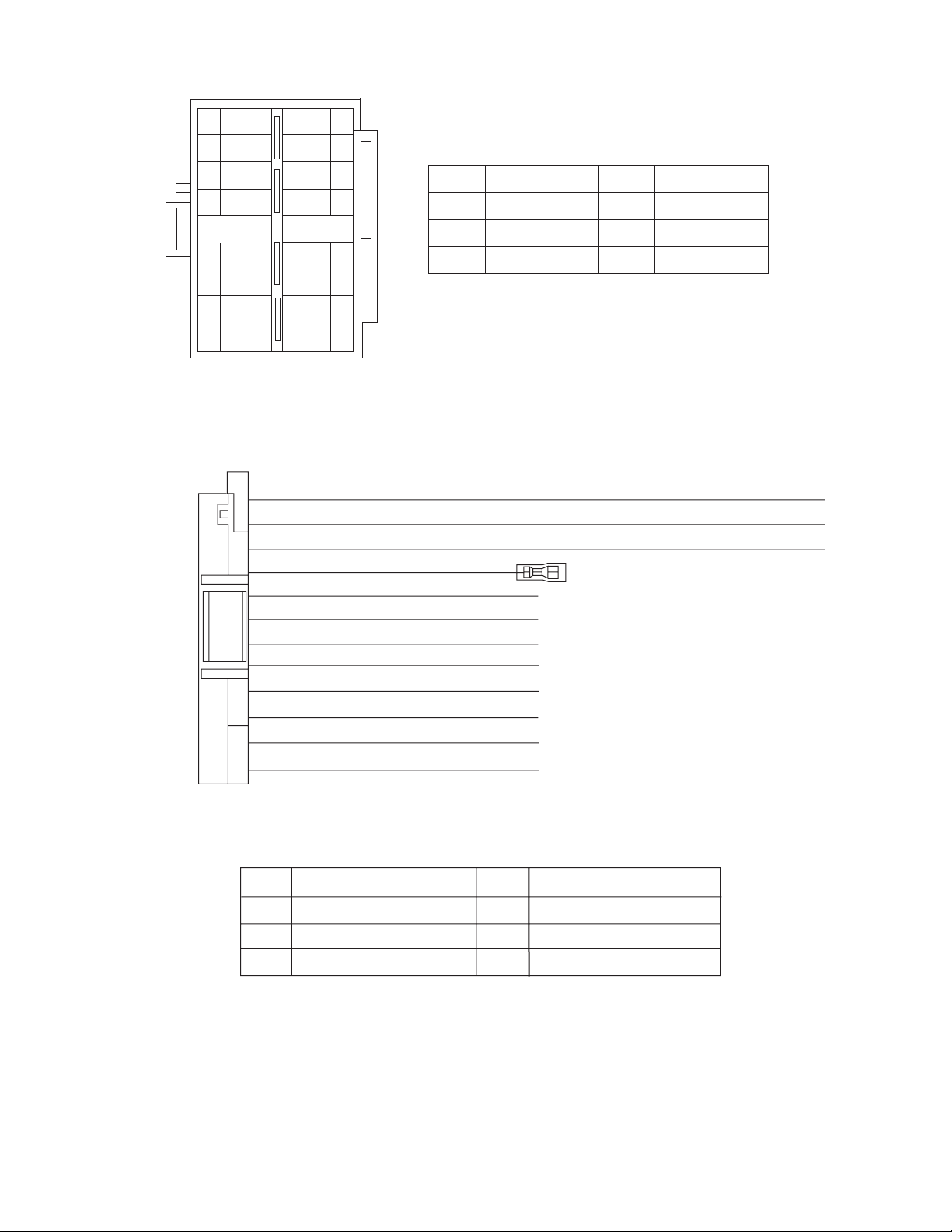
5.8 16 PIN CORD DIAGRAM
8
7
6
BL/WH
5
4
3
2
1
BK
RD
NC
WH
GN
VI
GY
WH/BK
GN/BK
VI/BK
GY/BK
16 YL
8 BK
7 RD
5 BL/WH REMOTE
4 WH
12 WH/BK
3 GN
11 GN/BK RL-
2 VI RR+
10 VI/BK
1 GY FR+
YL
NC
NC
NC
16
15
14
13
12
11
10
9
MEMORY
GND
ACC
FL+
FL-
RL+
RR-
BK
RD
BL
WH
Black
Red
Blue
White
GN
VI
GY
YL
Green
Violet
Gray
Yellow
9 GY/BK
RR
FR
FL
RL
Rear Right
Front Right
Front Left
Rear Left
FR-
REMOTE
ACC
MEMORY
GND
Remote out
ACC Line
Memory Backup Battery +
Ground
(No.MA143)1-29
Page 30

Victor Company of Japan, Limited
AV & MULTIMEDIA COMPANY CAR ELECTRONICS CATEGORY 10-1,1chome,Ohwatari-machi,Maebashi-city,371-8543,Japan
(No.MA143)
Printed in Japan
VPT
Page 31

CD RECEIVER KD-G456
‡§√◊ËÕ߇≈Ëπ CD KD-G456
ENGLISH
‰∑¬
For installation and connections, refer to the separate manual.
°√ÿ≥“¥Ÿ§ŸË¡◊Õ∑’Ë·¬°µË“ßÀ“° „π°“√µ‘¥µ—Èß·≈–°“√‡™◊ËÕ¡µËÕ
INSTRUCTIONS
§”·π–π”
GET0291-001A
[UH]
Page 32

¢ÈÕ¡Ÿ≈∑’˧«√∑√“∫‡°’ˬ«°—∫‡§√◊ËÕß√–∫∫‡≈‡´Õ√ÏÏ
1. º≈‘µ¿—≥±Ï‡§√◊ËÕß√–∫∫‡≈‡´Õ√Ï ™—Èπ 1
2. ¢ÈÕ§«√√–«—ß: ÀÈ“¡‡ª‘¥Ω“‡§√◊ËÕߥȓπ∫π ¿“¬„π‡§√◊ËÕßË«ππ’È ‰¡Ë¡’Ë«πª√–°Õ∫„¥Ê ∑’Ë®”‡ªÁπµÈÕ߇ª‘¥
‡æ◊ËÕµ√«®‡™Á§À√◊Õ´ËÕ¡ §«√„Àș˓ߺŸÈ‡™’ˬ«™“≠ ‡ªÁπºŸÈ√—∫º‘¥™Õ∫„π°“√´ËÕ¡‡§√◊ËÕß
3. ¢ÈÕ§«√√–«—ß: À“°‡ª‘¥‡§√◊ËÕß À√◊Õ‡¡◊ËÕµ—«≈ÁÕ§‡§√◊ËÕ߇’¬À√◊Õ™”√ÿ¥ ∑Ë“πÕ“®—¡º—‡¢È“°—∫·ß‡≈‡´Õ√Ï
∑’Ë¡Õ߇ÀÁπ·≈–‰¡Ë‡ÀÁπ¥È«¬µ“‡ª≈Ë“ §«√À≈’°‡≈’ˬߡ‘„ÀÈ—¡º—‚¥¬µ√ß °—∫·ß‡≈‡´Õ√Ï
4. °“√∑”©≈“°¢÷Èπ¡“„À¡Ë: ©≈“°√–∫ÿ¢ÈÕ§«√√–«—ß «“߉«È¥È“ππÕ°¢Õßµ—«‡§√◊ËÕß
‰∑¬
«‘∏’°“√µ—È߇§√◊ËÕß„À¡Ë
¢≥–°¥ªÿË¡ SEL (‡≈◊Õ°) §È“߉«È „ÀÈ°¥ (·µπ¥Ï∫“¬/‡ª‘¥‡§√◊ËÕß ‡∫“‡’¬ß≈ß) π“π 2 «‘π“∑’
§Õ¡æ‘«‡µÕ√Ï∑’ËÕ¬ŸË„π‡§√◊ËÕßÕ’°§√—ÈßÀπ÷Ëß
ªÿË¡
À¡“¬‡Àµÿ:
• §Ë“∑’Ë∑Ë“πµ—È߉«È≈Ë«ßÀπÈ“ ‡™Ëπ°“√µ—Èß∂“π’À√◊Õ°“√ª√—∫·µË߇’¬ß°Á®– ∂Ÿ°≈∫ÕÕ°‰ª¥È«¬
• ∂È“¡’·ºËπ´’¥’Õ¬ŸË ‡§√◊ËÕß®–¥’¥·ºËπ´’¥’ÕÕ°¡“ ‡¡◊ËÕ§ÿ≥µ—È߇§√◊ËÕß„À¡Ë √–«—ßլ˓∑”·ºËπ´’¥’À≈Ëπ
ªÿË¡ SEL (‡≈◊Õ°)
(·µπ¥Ï∫“¬/‡ª‘¥‡§√◊ËÕß ‡∫“‡’¬ß≈ß)
«‘∏’∫—ߧ—∫¥’¥·ºË𥑰ÏÕÕ°®“°‡§√◊ËÕß
¢≥–°¥ªÿË¡ (·µπ¥Ï∫“¬/‡ª‘¥‡§√◊ËÕß ‡∫“‡’¬ß≈ß) §È“߉«È „ÀÈ°¥ªÿË¡ 0 (¥’¥‡∑ªÕÕ°®“°‡§√◊ËÕß) π“π‡°‘π 2
«‘π“∑’ ®π°«Ë“·ºËπ¥‘°Ï®–¥’¥ÕÕ°®“°™ËÕß„Ë À“°‡§√◊ËÕ߉¡Ë√ŸÈ®—°·ºËπ¥‘°Ï À√◊Õ‰¡Ë“¡“√∂¥’¥·ºËπÕÕ°®“°‡§√◊ËÕ߉¥È
ªÿË¡ (·µπ¥Ï∫“¬/‡ª‘¥‡§√◊ËÕß ‡∫“‡’¬ß≈ß)
À¡“¬‡Àµÿ:
• À“°„™Èß“π‰¡Ë‰¥Èº≈ ¢Õ„ÀÈ≈Õßµ—È߇§√◊ËÕß„À¡Ë
•
√–«—ßլ˓∑”·ºË𥑰ÏÀ≈Ëπ ‡¡◊ËÕ¥’¥ÕÕ°®“°‡§√◊ËÕß
2
0 (¥’¥‡∑ªÕÕ°®“°‡§√◊ËÕß)
Page 33

¢Õ¢Õ∫æ√–§ÿ≥∑’ˇ≈◊Õ°´◊ÈÕº≈‘µ¿—≥±Ï¢Õß JVC °√ÿ≥“ÕË“π§”·π–π”∑—ÈßÀ¡¥‚¥¬≈–‡Õ’¬¥°ËÕπ°“√„™Èß“π
“√∫—≠
‡æ◊ËÕ„Àȇ¢È“„®™—¥‡®π ·≈–‡æ◊ËÕ„Àȉ¥È√—∫ª√–‘∑∏‘¿“æŸßÿ¥„π°“√„™Èß“πº≈‘µ¿—≥±Ï
«‘∏’°“√µ—È߇§√◊ËÕß„À¡É ................................................ 2
«‘∏’∫—ߧ—∫¥’¥·ºË𥑰ÏÕÕ°®“°‡§√◊ËÕß ....................... 2
«‘∏’„™ÈªÿË¡ MODE ................................................... 3
µ”·ÀπËߢÕߪÿË¡µË“ßÊ ........................................ 4
·ºß§«∫§ÿ¡
√’‚¡∑ §Õπ‚∑√≈ .............................................. 5
‡µ√’¬¡°“√„™È√’‚¡∑ §Õπ‚∑√≈ ............................... 6
.................................................... 4
°“√„™Èß“π‡∫◊ÈÕßµÈπ ............................................ 7
°“√‡ª‘¥‡§√◊ËÕß.................................................. 7
°“√µ—È߇«≈“ ..................................................... 8
°“√„™Èß“π«‘∑¬ÿ................................................... 9
°“√ø—ß«‘∑¬ÿ ..................................................... 9
°“√∫—π∑÷°∂“π’≈ß„πÀπË«¬§«“¡®”........................ 10
°“√√—∫§≈◊Ëπ∂“π’∑’˵—È߉«È≈Ë«ßÀπÈ“............................ 11
°“√„™Èß“π‡§√◊ËÕ߇≈Ëπ´’¥’ .................................... 12
°“√‡≈Ëπ´’¥’ ..................................................... 12
°“√§ÈπÀ“‡æ≈ßÀ√◊Õµ”·ÀπËß∑’˵ÈÕß°“√
∫π·ºËπ´’¥’ .................................................. 13
°“√‡≈◊Õ°‚À¡¥°“√‡≈Ëπ´’¥’ ................................... 14
°“√‡≈Ëπ CD Text ................................................... 15
°“√ÀÈ“¡¥’¥·ºË𥑰ÏÕÕ°®“°‡§√◊ËÕß ........................ 15
°“√∑”ß“π¢Õß MP3.................................................. 16
°“√‡≈Ëπ¥‘°Ï MP3 .................................................. 16
°“√§ÈπÀ“‰ø≈ÏÀ√◊Õµ”·ÀπËß∑’˵ÈÕß°“√ ∫π¥‘°Ï MP3 .... 17
°“√‡≈◊Õ°‚À¡¥°“√‡≈Ëπ MP3 .................................... 19
°“√ª√—∫·µË߇’¬ß .............................................. 20
°“√‡≈◊Õ°‚À¡¥µ—Èß‚ª√·°√¡‡’¬ß
(C-EQ: √Ÿª·∫∫Õ’§«Õ‰≈‡´Õ√Ï∑’ˇ≈◊Õ°‡Õß) ............. 20
°“√ª√—∫·µË߇’¬ß ............................................. 21
°“√∑”ß“π∑’Ë”§—≠լ˓ßÕ◊Ëπ ............................... 22
°“√‡ª≈’ˬπ§Ë“∑—Ë«‰ª (PSM) ................................. 22
°“√∂Õ¥·ºß§«∫§ÿ¡ .......................................... 24
°“√„™Èß“πµ—«‡ª≈’Ë¬π´’¥’ ..................................... 25
°“√‡≈Ëπ·ºËπ¥‘°Ï .............................................. 25
°“√‡≈◊Õ°‚À¡¥‡≈Ëπ´’¥’........................................ 28
°“√„™Èß“πÕÿª°√≥Ï¿“¬πÕ°
„™ÈÕÿª°√≥ÏÕ◊Ëπ°—∫‡§√◊ËÕß....................................... 29
............................... 29
¢ÈÕ¡Ÿ≈‡Ã‘Ë¡‡µ‘¡ .................................................... 30
°“√‡≈Ëπ·ºËπ CD-R À√◊Õ CD-RW ........................... 30
°“√‡≈Ëπ·ºËπ MP3 ................................................. 30
°“√·°Èª—≠À“‡∫◊ÈÕßµÈπ........................................ 31
°“√¥Ÿ·≈√—°…“ .................................................... 34
¢ÈÕ¡Ÿ≈®”‡æ“–..................................................... 35
«‘∏’„™ÈªÿË¡ MODE
∂È“°¥ªÿË¡ MODE ‡§√◊ËÕß®–‰ª∑’Ë‚À¡¥ø—ß°Ï™—Ëπ „π¢≥–∑’˪ÿË¡µ—«‡≈¢·≈–ªÿË¡ 5/∞ ®–∑”ÀπÈ“∑’ˇªÁπªÿË¡‡≈◊Õ°ø—ß°Ï™—Ëπ
µ—«Õ¬Ë“ß: ªÿË¡À¡“¬‡≈¢
2 ∑”ÀπÈ“∑’ˇªÁπªÿË¡ MO (‡’¬ß‡¥’¬«∏√√¡¥“)
‰∑¬
À“°µÈÕß°“√„ÀȪÿË¡‡À≈Ë“π’È°≈—∫‰ª∑”ÀπÈ“∑’ˇ¥‘¡Õ’°§√—ÈßÀ≈—ß®“°°¥ªÿË¡
«‡≈¢„¥Ê ®π°√–∑—Ëß‚À¡¥°“√∑”ß“πµË“ßÊ ∂Ÿ°≈∫ÕÕ°À¡¥
À“°°¥ªÿË¡‚À¡¥À√◊Õ MODE Õ’°§√—Èß °Á®–‡ªÁπ°“√¬°‡≈‘°‚À¡¥°“√∑”ß“π¥È«¬‡À¡◊Õπ°—π
•
(—≠≠“≥ “MODE” À“¬‰ª®“°ÀπÈ“ª—¥)
MODE „ÀÈ√Õ 5 «‘π“∑’‚¥¬¡‘µÈÕß°¥ªÿË¡µ—
°ËÕπ°“√„™È
Õÿ≥À¿Ÿ¡‘¿“¬„π√∂....
*
‡æ◊ËÕ§«“¡ª≈Õ¥¿—¬....
• ‰¡Ë§«√‡æ‘Ë¡√–¥—∫‡’¬ß¥—߇°‘π‰ª ‡æ√“–®–∑”„Àȉ¡Ë‰¥È¬‘π‡’¬ß®“°
¿“¬πÕ° ´÷ËßÕ“®‡°‘¥Õ—πµ√“¬¢≥–¢—∫√∂‰¥È
• §«√À¬ÿ¥√∂°ËÕπ°“√„™Èß“π∑’ˬÿË߬“°´—∫´ÈÕπ
*
À“°®Õ¥√∂∑‘È߉«È„π∑’Ë∑’Ë¡’Õ“°“»√ÈÕπÀ√◊ÕÀ𓫇ªÁπ‡«≈“π“π
§«√√Õ®π°«Ë“Õÿ≥À¿Ÿ¡‘¿“¬„π√∂°≈—∫ŸË√–¥—∫ª°µ‘°ËÕπ‡√‘Ë¡„™È
ß“π‡§√◊ËÕß
‰ø—≠≠“≥°“√π—∫∂Õ¬À≈—ß
3
Page 34

·ºß§«∫§ÿ¡
‰∑¬
µ”·ÀπËߢÕߪÿË¡µË“ßÊ
ÀπÈ“®Õ
1 ªÿË¡ (·µπ¥Ï∫“¬/‡ª‘¥‡§√◊ËÕß ‡∫“‡’¬ß≈ß)
2 ªÿË¡ SEL (‡≈◊Õ°)
3 ªÿË¡ CD CD-CH (‡§√◊ËÕ߇≈Ëπ´’¥’)
4
ªÿË¡ FM/AM
5 ™ËÕß„Ë·ºËπ
6 ÀπÈ“®Õ
7 ªÿË¡ 0 (¥’¥‡∑ªÕÕ°®“°‡§√◊ËÕß)
8 ªÿË¡ EQ (Õ’§«Õ‰≈‡´Õ√ú)
9 √’‚¡∑‡´Áπ‡´Õ√Ï
p ªÿË¡ 5 (¢÷Èπ)
ªÿË¡
+10
q ·ªÈπ§«∫§ÿ¡
w ªÿË¡µ—«‡≈¢
e ªÿË¡ MO (‡’¬ß‡¥’¬«∏√√¡¥“)
r ªÿË¡ SSM (®¥®”∂“π’‡√’¬ßµ“¡≈”¥—∫§«“¡·√ߢÕß—
≠≠“≥)
t ªÿË¡ RPT (´È”)
y ªÿË¡ RND (ÿË¡)
u ªÿË¡ MODE
i ªÿË¡ DISP (¿“æÀπÈ“®Õ)
o ªÿË¡ 4/¢
; ªÿË¡ („™È∂Õ¥·ºß§«∫§ÿ¡ÕÕ°)
a ªÿË¡ ∞ (≈ß)
ªÿË¡
4
–10
ÀπÈ“®Õ
s ‰ø—≠≠“≥°“√√—∫§≈◊Ëπ‡’¬ß
MO (‡’¬ß‡¥’¬«∏√√¡¥“), ST (‡’¬ß‡µÕ√‘‚Õ)
d ‰ø MP3
f ‰ø CH (‡§√◊ËÕ߇≈Ëπ´’¥’)
• ‰ø®–µ‘¥‡¡◊ËÕµËÕ°—∫´’¥’‡™π‡®Õ√Ï
‰ø CD
g
h ‰ø·¥ß√“¬°“√‡≈Ëπ/‚À¡¥
RND (ÿË¡) (·ºËπ) (‚ø≈‡¥Õ√Ï)
RPT (´È”)
j ‰ø LOUD (µ—Èߧ˓‡’¬ß¥—ß-‡∫“)
k ‰ø EQ (Õ’§«Õ‰≈‡´Õ√Ï)
l ‚À¡¥‡’¬ß (C-EQ:
√Ÿª·∫∫Õ’§«Õ‰≈‡´Õ√Ï∑’ˇ≈◊Õ°‡Õß)
ROCK, CLASSIC, POPS, HIP HOP, JAZZ,
USER
• ¬—ß∑”ÀπÈ“∑’Ë·¥ß‡«≈“π—∫∂Õ¬À≈—ߥȫ¬
/
—≠≠“≥·¥ß¢ÈÕ¡Ÿ≈¥‘°Ï
TAG (ID3 Tag), (‚ø≈‡¥Õ√Ï), (·∑√Á°/‰ø≈Ï)
z ®Õ¿“æÀ≈—°
x ·¥ß´Õ√Ï
‰ø·¥ß√–¥—∫‡’¬ß
c ‰ø Tr (·∑√Á°)
Page 35

√’‚¡∑ §Õπ‚∑√≈
1 • „™È°¥‡æ◊ËÕ‡ª‘¥‡§√◊ËÕß ¢≥–∑’ˇ§√◊ËÕߪ‘¥∑”ß“π
• „™È°¥‡æ◊ËÕª‘¥‡§√◊ËÕß ‚¥¬°¥§È“߉«È®π°√–∑—Ëߧ”
“SEE YOU” ª√“°Ø∫πÀπÈ“®Õ
• „™È°¥‡æ◊ËÕ≈¥√–¥—∫§«“¡¥—ߢÕ߇’¬ß™—Ë«§√“«
‚¥¬°¥·≈È«ª≈ËÕ¬
°¥Õ’°§√—Èß√–¥—∫§«“¡¥—ߢÕ߇’¬ß°Á®–°≈—∫‡À¡◊Õπ‡¥‘¡
2 •
„™È‡≈◊Õ°™Ë«ß§«“¡∂’Ë¢Õߧ≈◊Ëπ«‘∑¬ÿ ¢≥–ø—ß«‘∑¬ÿ ∑ÿ°§√
∑’Ë°¥ªÿË¡π’È ™Ë«ß§«“¡∂’Ë¢Õߧ≈◊Ëπ«‘∑¬ÿ®–
‡ª≈’Ë¬π‰ª‡√◊ËÕ¬Ê
• ¢È“¡°≈—∫‰ª∑’ˉø≈Ï·√°¢Õß‚ø≈‡¥Õ√Ï∂—¥‰ª¢≥–°”≈—
ßøߥ‘°Ï
MP3
‡¡◊ËÕ°¥ªÿË¡·µË≈–§√—Èß √–∫∫®–¬È“¬‰ª¬—ß‚ø≈‡¥Õ√Ï∂—
¥‰ª·≈–‡√‘Ë¡‡≈Ëπ‰ø≈Ï·√°¢Õß‚ø≈‡¥Õ√Ïπ—Èπ
• ¢≥–‡≈Ëπ·ºËπ MP3 „πµ—«‡ª≈’Ë¬π´’¥’´÷Ëß„™Èß“π‰¥È°—
∫·ºËπ MP3;
–
„™È¢È“¡‰ª¬—ߥ‘°Ï·ºËπ∂—¥‰ª‡¡◊ËÕ°¥·≈È«ª≈ËÕ¬
–„™È¢È“¡‰ª¬—ß‚ø≈‡¥Õ√Ï∂—¥‰ª‡¡◊ËÕ°¥§È“߉«È
À¡“¬‡Àµÿ:
¢≥–‡≈Ëπ·ºËπ´’¥’„πµ—«‡ª≈’Ë¬π´’¥’ ‡§√◊ËÕß®–
‡≈Ëπ¢È“¡‰ª¬—ß·ºËπ∂—¥‰ª‡¡Õ
3 •
„™È‡≈◊Õ°∂“π’«‘∑¬ÿ∑’ˉ¥Èµ—Èß‚ª√·°√¡‰«È·≈È« ¢≥–ø—ß«‘∑¬ÿ
∑ÿ°§√—Èß∑’Ë°¥ªÿË¡π’È À¡“¬‡≈¢∂“π’«‘∑¬ÿ®–‡æ‘Ë¡¢÷Èπ‡√◊ËÕ¬Ê
·≈–®–‡√‘Ë¡‡≈Ëπ√“¬°“√¢Õß∂“π’∑’ˇ≈◊Õ°‰«
• ¢È“¡°≈—∫‰ª∑’ˉø≈Ï·√°¢Õß‚ø≈‡¥Õ√Ï°ËÕπÀπÈ“¢≥–°”≈—
ßø—ߥ‘°Ï
MP3
‡¡◊ËÕ°¥ªÿË¡·µË≈–§√—Èß √–∫∫®–¬È“¬‰ª¬—
ß‚ø≈‡¥Õ√Ï°ËÕπÀπÈ“·≈–‡√‘Ë¡‡≈Ëπ‰ø≈Ï·√°¢Õß‚ø≈‡¥Õ√Ïπ—Èπ
• ¢≥–‡≈Ëπ·ºËπ MP3 „πµ—«‡ª≈’Ë¬π´’¥’´÷Ëß„™Èß“π‰¥È°—∫·ºËπ
MP3;
– „™È¢È“¡‰ª¬—ߥ‘°Ï·ºËπ°ËÕπÀπÈ“‡¡◊ËÕ°¥·≈È«ª≈ËÕ¬
– „™È¢È“¡‰ª¬—ß‚ø≈‡¥Õ√Ï°ËÕπÀπÈ“‡¡◊ËÕ°¥§È“߉«È
À¡“¬‡Àµÿ:
4
∑”ÀπÈ“∑’ˇ™Ëπ‡¥’¬«°—∫ÀπÈ“ª—¥§«∫§ÿ¡¢Õß™ÿ¥ª√–°Õ∫À≈—°
À¡“¬‡Àµÿ:
5
„™È‡≈◊Õ°‚À¡¥‡’¬ß (
¢≥–‡≈Ëπ·ºËπ´’¥’„πµ—«‡ª≈’Ë¬π´’¥’ ‡§√◊ËÕß®–
‡≈Ëπ¢È“¡‰ª¬—ß·ºËπ°ËÕπÀπÈ“‡¡Õ
ªÿË¡π’È®–‰¡Ë∑”ß“π”À√—∫°“√ª√—∫‚À¡¥µ—Èß √“¬°“√∑’Ë
µÈÕß°“√
C-EQ:
√Ÿª·∫∫Õ’§«Õ‰≈‡´Õ√Ï∑’ˇ≈◊Õ°‡Õß)
∑ÿ°§√—Èß∑’Ë°¥ªÿË¡π’È ‚À¡¥‡’¬ß (C-EQ) ®–‡ª≈’Ë¬π‰ª‡√◊ËÕ¬Ê
6 „™È‡≈◊Õ°·À≈Ëß„Àȇ’¬ß
∑ÿ°§√—Èß∑’Ë°¥ªÿË¡π’È ·À≈Ëß„Àȇ’¬ß®–‡ª≈’Ë¬π‰ª‡√◊ËÕ¬Ê
7 • „™È§ÈπÀ“∂“π’«‘∑¬ÿ ¢≥–ø—ß«‘∑¬ÿ
• „™È‡≈◊ËÕπÀ“‡æ≈ßÀ√◊Õ‰ø≈Ï∑’ËÕ¬ŸË¢È“ßÀπÈ“À√◊բȓßÀ≈—ß
ßô
լ˓ß√«¥‡√Á« ‚¥¬°¥§È“߉«È¢≥–ø—ß·ºË𥑰Ï
• „™È¢È“¡‰ª¬—ßµÈπ‡æ≈ßÀ√◊Õ‰ø≈Ï∂—¥‰ª À√◊Õ∂Õ¬°≈—∫‰ª¬—
ßµÈπ‡æ≈ߢÕ߇æ≈߇¥‘¡ (À√◊Õ∑’ˇæ‘Ëߺ˓π¡“)
‚¥¬°¥ªÿË¡π’ȇ撬ߗÈπÊ ¢≥–ø—ß·ºË𥑰Ï
È
‰∑¬
5
Page 36

‡µ√’¬¡°“√„™È√’‚¡∑ §Õπ‚∑√≈
°ËÕπ„™È√’‚¡∑§Õπ‚∑√≈:
• ¬◊Ëπ√’‚¡∑§Õπ‚∑√≈‰ª¬—ß√’‚¡∑‡´Áπ‡´Õ√Ï∑’ˇ§√◊ËÕß
լ˓„ÀÈ¡’«—µ∂ÿ¢«“ß√–À«Ë“ß°≈“ß
√’‚¡∑‡´Áπ‡´Õ√Ï
‰∑¬
3. ‡≈◊ËÕπË«π∑’Ë„Ë∂Ë“π°≈—∫‡¢È“∑’ˇ¥‘¡
‡≈◊ËÕπË«π∑’Ë„Ë∂Ë“π°≈—∫‡¢È“∑’ˇ¥‘¡¥È«¬°“√¥—π‡¢È“‰ª®π
‰¥È¬‘π‡’¬ß≈ÁÕ§
(¥È“πÀ≈—ß)
• լ˓„ÀÈ√’‚¡∑‡´Áπ‡´Õ√Ï¢Õ߇§√◊ËÕß‚¥π·ß®È“
(·ß·¥¥‚¥¬µ√ß À√◊Õ·ß®“°À≈Õ¥‰ø)
„Ë∂Ë“π
‡¡◊ËÕ√’‚¡∑§Õπ‚∑√≈‡√‘Ë¡§«∫§ÿ¡‰¥ÈπÈÕ¬≈ßÀ√◊Õ¥ÈÕ¬
ª√–‘∑∏‘¿“æ „Àȇª≈’ˬπ∂Ë“π„À¡Ë
1. ¥÷ßË«π∑’Ë „Ë∂Ë“πÕÕ°¡“
1)
„™Èª≈“¬ª“°°“≈Ÿ°≈◊ËπÀ√◊Õ¢Õß∑’Ë¡’≈—°…≥–∑’˧≈È“¬°—π
¥πË«π∑’Ë„Ë∂Ë“πÕÕ°¡“µ“¡∑‘»∑“ߢÕß≈Ÿ°»√∑’Ë·¥ß
„π√Ÿª
2) ¥÷ßË«π∑’Ë„Ë∂Ë“πÕÕ°¡“
(¥È“πÀ≈—ß)
2. „Ë∂Ë“π
‡≈◊ËÕπ∂Ë“π‡¢È“„π∑’Ë„Ë À—π¥È“π + ¢÷Èπ‡æ◊ËÕ„ÀÈ∂Ë“πµ‘¥π‘∑°—
∫∑’Ë„Ë
§”‡µ◊Õπ:
• §«√‡°Á∫∂Ë“π‰«È„π∑’Ë∑’ˇ¥Á°‡Õ◊ÈÕ¡‰¡Ë∂÷ß
À“°‡¥Á°°≈◊π∂Ë“π‡¢È“‰ª‚¥¬∫—߇Ց≠ „ÀÈ√’∫𔇥Á°Ëß·æ∑¬Ï∑—π∑’
• ‰¡Ë§«√™“√Ï® µ—¥ ∂Õ¥™‘ÈπË«πÀ√◊Õ‡Õ“‰ø≈π∂Ë“π
À√◊Õ‚¬π∂Ë“π‡¢È“°Õ߉ø
°“√°√–∑”‡™Ëππ’ÈÕ“®∑”„ÀÈ∂Ë“π√ÈÕπ ·µ°√–‡∫‘¥ À√◊Õµ‘¥‰ø‰¥È
• ‰¡Ë§«√«“ß∂Ë“π‰«È°—∫«—¥ÿ∑’Ë∑”®“°‚≈À–
°“√°√–∑”‡™Ëππ’ÈÕ“®∑”„ÀÈ∂Ë“π√ÈÕπ ·µ°√–‡∫‘¥ À√◊Õµ‘¥‰ø‰¥È
• ‡¡◊ËÕµÈÕß°“√∑‘ÈßÀ√◊Õ‡°Á∫∂Ë“π „ÀÈ„™È‡∑ªÀ√◊Õ‘Ëß∑’ˇªÁπ©π«π
АЛХАяИ¡∂Л“π‡’¬°ЛХπ ¡‘©–π—Иπ Х“®∑”„АИ∂Л“π√ИХπ ·µ°√–‡∫‘¥
А√◊Хµ‘¥‰ш¢чИπ‰¥И
• ‰¡Ë§«√„™È§’¡À√◊Õ«—¥ÿ„¥Ê ∑’Ë¡’≈—°…≥–§≈È“¬°—π·¬ß‡¢È“‰ª„π∂Ë“π
°“√°√–∑”‡™Ëππ’ÈÕ“®∑”„ÀÈ∂Ë“π√ÈÕπ ·µ°√–‡∫‘¥ À√◊Õµ‘¥‰ø‰¥È
¢ÈÕ§«√√–«—ß:
լ˓«“ß√’‚¡∑§Õπ‚∑√≈‰«È„π∑’Ë∑’Ë¡’·ß·¥¥ËÕß∂÷ß‚¥¬µ√ß ‡ªÁπ√–¬–
‡«≈“π“π (‡™Ëπ·ºßÀπÈ“√∂) ¡‘©–π—Èπ √’‚¡∑§Õπ‚∑√≈Õ“®™”√ÿ¥À√◊Õ‡
’¬À“¬‰¥È
∂Ë“π°ÈÕπ·∫π∑’Ë∑”®“°
≈‘‡∏’¬¡ (À¡“¬‡≈¢º≈‘µ¿—
≥±Ï:
CR2025)
6
Page 37

°“√„™Èß“π‡∫◊ÈÕßµÈπ
3
1
2
‰∑¬
°“√‡ª‘¥‡§√◊ËÕß
1
‡ª‘¥‡§√◊ËÕß
À¡“¬‡Àµÿ°“√„™Èß“π‚¥¬°¥ªÿË¡‡¥’¬«:
‡¡◊ËÕ‡≈◊Õ°„™Èß“π‡§√◊ËÕß√—∫«‘∑¬ÿ„π¢—ÈπµÕπ∑’Ë
µ“¡¢È“ß≈Ë“ßπ’È ‡§√◊ËÕß°Á®–‡ª‘¥‡Õß‚¥¬Õ—µ‚π¡—µ‘
‚¥¬‰¡ËµÈÕß°¥ªÿË¡π’ȇæ◊ËÕ‡ª‘¥‡§√◊ËÕß
2
‡≈◊Õ°„™Èß“π
°“√§ÈπÀ“§≈◊Ëπ«‘∑¬ÿ (FM À√◊Õ AM)
°√ÿ≥“¥ŸÀπÈ“ 9 – 11
°“√„™Èß“π‡§√◊ËÕ߇≈Ëπ´’¥’
°√ÿ≥“¥ŸÀπÈ“
°“√‡≈Ëπ·ºËπ MP3
°√ÿ≥“¥ŸÀπÈ“ 16 – 19
√‡ª≈’Ë¬π´’¥’
°√ÿ≥“¥ŸÀπÈ“ 25 – 28
°“√„™Èß“πÕÿª°√≥Ï¿“¬πÕ° (LINE IN)
°√ÿ≥“¥ŸÀπÈ“ 29
3
ª√—∫§«“¡¥—ߢÕ߇’¬ß
12 – 15
‡æ‘Ë¡§«“¡¥—ߢÕ߇’¬ß
≈¥§«“¡¥—ߢÕ߇’¬ß
√–¥—∫§«“¡¥—ߢÕ߇’¬ß®–ª√“°Ø¢÷Èπ
‰ø·¥ß√–¥—∫‡’¬ß
4
ª√—∫·µË߇’¬ßµ“¡µÈÕß°“√
2
(°√ÿ≥“¥ŸÀπÈ“ 20 – 21)
°“√≈¥§«“¡¥—ߢÕ߇’¬ß„π∑—π∑’
°¥ªÿË¡ —ÈπÊ ¢≥–ø—ß«‘∑¬ÿ™ËÕß„¥°Á‰¥È ‡§√◊ËÕßÀ¡“¬
“ATT” ®–°√–æ√‘∫¢÷Èπ∑’ËÀπÈ“®Õ ·≈È«√–¥—∫‡’¬ß®–≈¥≈ß
„π∑—π∑’ À“°®–∑”„Àȇ’¬ß¥—߇∑Ë“‡¥‘¡ „ÀÈ°¥ªÿË¡‡¥‘¡—ÈπÊ
Õ’°§√—Èß
•
À“°µÈÕß°“√√–¥—∫‡’¬ß°≈—∫§◊πŸË¿“懥‘¡
„ÀÈÀ¡ÿπ·ªÈπ§«∫§ÿ¡
«‘∏’ª‘¥‡§√◊ËÕß
°¥ªÿË¡ §È“߉«Èπ“π°«Ë“ 1 «‘π“∑’
“SEE YOU” ®–ª√“°Ø¢÷Èπ ®“°π—Èπ‡§√◊ËÕß°Á®–ª‘¥
• À“°ª‘¥‡§√◊ËÕߢ≥–°”≈—ßø
ß·ºËπ¥‘°Ï·≈È«µËÕ¡“‡ª‘¥‡§√◊ËÕß„À¡ËË
‡§√◊ËÕß®–‡√‘Ë¡‡≈Ëπ‡æ≈ßµËÕ®“°§√—Èß°ËÕπ∑’ËÀ¬ÿ¥‡≈Ëπ‰ª
¢âÕ§«√√–«—ß„π°“√ª√—∫§«“¡¥—߇’¬ß:
‡«≈“‡≈Ëπ¥‘°Ï ª°µ‘®–‡°‘¥‡’¬ß·∑√°πÈÕ¬¡“°‡¡◊ËÕ‡ª√’¬∫‡∑’¬∫°—∫
°“√‡≈Ëπլ˓ßÕ◊Ëπ ¬°µ—«Õ¬Ë“ß ¢≥–ø—ß«‘∑¬ÿ·≈È«ª√—∫§«“¡¥—ß
‡’¬ß‡æ‘Ë¡¢÷Èπ ®“°π—Èπ‡ª≈’Ë¬π¡“‡≈Ëπ¥‘°Ï §«“¡¥—ߢÕ߇’¬ß®–
‡æ‘Ë¡¢÷Èπլ˓ß√«¥‡√Á« ´÷ËßÕ“®¡’º≈∑”„ÀÈ≈”‚æ߇’¬‰¥È ¥—ßπ—Èπ
®÷ߧ«√≈¥§«“¡¥—ߢÕ߇’¬ß °ËÕπ∑’Ë®–‡ª≈’Ë¬π¡“‡≈Ëπ¥‘°Ï ®“°π—Èπ
®÷ߧËÕ¬Ê ª√—∫§«“¡¥—߇’¬ßµ“¡∑’˵ÈÕß°“√¢≥–∑’ˇ≈Ë𥑰Ï
7
Page 38

‰∑¬
°“√µ—È߇«≈“
1
°¥ªÿË¡ SEL (‡≈◊Õ°) §È“߉«È‡°‘π°«Ë“ 2
«‘π“∑’‡æ◊ËÕ„ÀÈ√“¬°“√„¥√“¬°“√Àπ÷Ëß
PSM ª√“°Ø∫πÀπÈ“ª—¥
¢Õß
:
PSM
‚ª√¥¥ŸÀπÈ“ 22)
(
2
µ—Èß™—Ë«‚¡ß
1 ‡≈◊Õ° “CLOCK H” (™—Ë«‚¡ß)
À“°‰¡Ë‰¥È·¥ßÕ¬ŸË∫πÀπÈ“®Õ
2 µ—Èß™—Ë«‚¡ß
12
3
µ—Èßπ“∑’
1 ‡≈◊Õ° “CLOCK M” (π“∑’)
2 µ—Èßπ“∑’
12
À“°µÈÕß°“√µ√«®¥Ÿ‡«≈“ª—®®ÿ∫—πÀ√◊Õ‡ª≈’ˬπ‚À¡¥ÀπÈ“®Õ
°¥ªÿË¡
DISP (¿“æÀπÈ“®Õ)
´È”À≈“¬Ê§√—Èß ·≈–∑ÿ°§√—È
ß∑’Ë∑Ë“π°¥ªÿË¡π’È ‚À¡¥·¥ß®–
‡ª≈’Ë¬π‰ªµ“¡¢È“ß≈Ë“ßπ’È:
• √–À«Ë“ß°“√„™Èß“π ‡§√◊ËÕß√—∫«‘∑¬ÿÿ:
§«“¡∂’Ë π“Ñ°“
• √–À«Ë“ß°“√‡≈Ë𥑰Ï:
√–¬–‡«≈“∑’ˉ¥È‡≈Ëπ
‡æ≈߉ª·≈È«
™◊ËÕ‡æ≈ß
™◊ËÕ¥‘°Ï/π—°√ÈÕß
π“Ñ°“
À¡“¬‡Àµÿ:
• „π¢≥–∑’ˇ≈Ëπ´’¥’‡æ≈ß·∫∫‡°Ë“ ®–¡’¢ÈÕ§«“¡ “
ª√“°Ø¢÷Èπ¡“·∑π™◊ËÕ¥‘°Ï/»‘≈ª‘π·≈–™◊ËÕ‡æ≈ß
• ”À√—∫°“√‡ª≈’ˬπ‚À¡¥·¥ß¢ÈÕ§«“¡„π °“√‡≈Ëπ
À√◊Õ¥‘°Ï
MP3
‚ª√¥¥ŸÀπÈ“ 15 ·≈– 17 ‡æ‘Ë¡‡µ‘¡
•
√–À«Ë“߇≈ËπÕÿª°√≥Ï¿“¬πÕ°
LINE IN π“Ñ°“
• ¢≥–ª‘¥‡§√◊ËÕß:
:
NO NAME
CD Text
”
‡§√◊ËÕß®–‡ª‘¥ ‡«≈“¢Õßπ“Ñ°“°Á®–ª√“°Ø¢÷Èπª√–¡“≥
5 «‘π“∑’·≈È«‡§√◊ËÕß°Á®–ª‘¥
4
‡√Á®‘Èπ°“√µ—Èߧ˓
8
Page 39

°“√„™Èß“π«‘∑¬ÿ
‰∑¬
°“√ø—ß«‘∑¬ÿ
§ÿ≥“¡“√∂§ÈπÀ“™ËÕß∂“π’«‘∑¬ÿ‰¥È¥È«¬µ—«‡ÕßÀ√◊եȫ¬√–
∫∫Õ—µ‚π¡—µ‘
°“√§ÈπÀ“™ËÕß∂“π’¥È«¬√–∫∫§ÈπÀ“
Õ—µ‚π¡—µÀ√◊Õ‘: À√◊ÕÕÕ‚µ‡´‘√Ï™
1
‡≈◊Õ°√–∫∫§≈◊Ëπ (FM1 – 3, AM)
∑ÿ°§√—Èß∑’Ë°¥ªÿË¡π’È
√–∫∫§≈◊Ëπ«‘∑¬ÿ®–‡ª≈’Ë¬π‰ª¥—ßπ’È:
®–«Ë“ߢ÷Èπ‡¡◊ËÕ‰¥È√—∫—≠≠“≥°√–®“¬‡’¬ß·∫∫
FM ‡µÕ√‘‚Õ∑’Ë¡’—≠≠“≥·√ßæÕ
·∫π¥Ï∑’Ë∑Ë“π‡≈◊Õ°®–ª√“°Ø¢÷Èπ
À¡“¬‡Àµÿ:
‡§√◊ËÕß√—∫§≈◊Ëπ«‘∑¬ÿπ’È¡’√–∫∫§≈◊Ëπ FM Õ¬ŸË 3 ·∫∫
(FM1, FM2 ·≈– FM3) “¡“√∂„™Èø—ß°“√
°√–®“¬‡’¬ß¢Õß√–∫∫
FM ™ËÕß„¥°Á‰¥È
À“°µÈÕß°“√À¬ÿ¥°“√§ÈπÀ“°ËÕπ®–‰¥È√—∫§≈◊Ëπ∂“π’
„ÀÈ°¥ªÿË¡‡¥‘¡∑’Ë∑Ë“π„™È„π°“√§ÈπÀ“
°“√§ÈπÀ“™ËÕß∂“π’¥È«¬µ—«‡ÕßÀ√◊Õ:
·¡ππ«≈‡´‘√Ï™
1
‡≈◊Õ°√–∫∫§≈◊Ëπ (FM1 – 3, AM)
∑ÿ°§√—Èß∑’Ë°¥ªÿË¡π’È
√–∫∫§≈◊Ëπ«‘∑¬ÿ®–‡ª≈’Ë¬π‰ª¥—ßπ’È:
À¡“¬‡Àµÿ:
‡§√◊ËÕß√—∫§≈◊Ëπ«‘∑¬ÿπ’È¡’√–∫∫§≈◊Ëπ FM Õ¬ŸË 3 ·∫∫
(FM1, FM2 ·≈– FM3) “¡“√∂„™Èø—ß°“√
°√–®“¬‡’¬ß¢Õß√–∫∫
2
°¥ªÿË¡ ¢ À√◊Õ 4
FM ™ËÕß„¥°Á‰¥È
§È“߉«È®π°«Ë“ “M” (§«∫§ÿ¡‡Õß) ®–
‡√‘Ë¡°–æ√‘∫ ∫πÀπÈ“®Õ
2
‡√‘Ë¡§ÈπÀ“∂“π’
‡æ◊ËÕ§ÈπÀ“∂“π’∑’Ë¡’§«“¡∂’Ë
∑’˟ߢ÷Èπ
‡æ◊ËÕ§ÈπÀ“∂“π’∑’Ë¡’§«“¡∂’Ë∑’˵˔≈ß
‡¡◊ËÕ√—∫§≈◊Ëπ∂“π’‰¥È·≈È« °“√§ÈπÀ“®–À¬ÿ¥
¡’µÉÕÀπâ“∂—¥‰ª
9
Page 40

‰∑¬
3
¢≥–∑’Ë “M” (§«∫§ÿ¡‡Õß) °”≈—ß°–
æ√‘∫Õ¬ŸË „ÀȪ√—∫§≈◊Ëπ«‘∑¬ÿ„Àȵ√ß°—∫
™ËÕß∂“π’∑’˵ÈÕß°“√
‡æ◊ËÕø—ß∂“π’∑’Ë¡’§«“¡∂’˟ߢ÷Èπ
‡æ◊ËÕø—ß∂“π’∑’Ë¡’§«“¡∂’˵˔≈ß
°“√∫—π∑÷°∂“π’≈ß„πÀπË«¬§«“¡®”
∑Ë“π“¡“√∂„™È«‘∏’„¥°Á‰¥È„π 2 «‘∏’π’È ‡æ◊ËÕ∫—π∑÷°§≈◊Ëπ∂“π’
«‘∑¬ÿ‰« „πÀπË«¬§«“¡®”
• µ—Èß∂“π’ FM ≈Ë«ßÀπÈ“‚¥¬Õ—µ‚π¡—µ‘: SSM
(Strong-station Sequential Memory
®¥®”∂“π’‡√’¬ßµ“¡≈”¥—∫§«“¡·√ߢÕß—≠≠“≥
•
°“√µ—Èß∂“π’≈Ë«ßÀπÈ“¥È«¬µ—«‡Õß∑—Èß∂“π’√–∫∫
°“√µ—Èß∂“π’
FM
≈Ë«ßÀπÈ“Õ—µ‚π¡—µ‘:
FM
)
·≈–√–∫∫
SSM
AM
• À“°ª≈ËÕ¬π‘È«®“°ªÿË¡∑’Ë°¥ ‚À¡¥°“√À“§≈◊Ëπ¥È«¬µ—
«‡Õß®–
À¬ÿ¥∑”ß“π‚¥¬Õ—µ‚π¡—µ‘ À≈—
ß®“°ºË“π‰ª·≈È«
• À“°°¥ªÿË¡§È“߉«È §«“¡∂’Ë®–‡ª≈’Ë¬π‰ª‡√◊ËÕ¬Ê
(™Ë«ßÀ˓ߧ◊Õ§√—Èß≈–
5 «‘π“∑’
50 kHz „π°√≥’∑’ˇªÁπ FM
·≈–§√—Èß≈– 9 kHz ”À√—∫§≈◊Ëπ AM) ®π°«Ë“®–
ª≈ËÕ¬¡◊Õ
‡¡◊ËÕ°“√°√–®“¬‡’¬ß‡µÕ√‘‚Õ FM √—∫
ø—߉¥È¬“°:
1 °¥ªÿË¡ MODE °“√‡æ◊ËÕ‡¢È“ŸË‚À¡¥
°“√∑”ß“π¢≥– ø—ß°“√°√–®“¬‡’¬ß√–∫∫
FM ‡µ√‘‚Õ ‰ø—≠≠“≥
2 °¥ªÿË¡ MO (‡’¬ß‡¥’¬«∏√√¡¥“) ¢≥–
“MODE” ¬—ß°√–æ√‘∫Õ¬ŸË∫πÀπÈ“®Õ
§”«Ë“Á
“MONO” ª√“°Ø¢÷Èπ∫πÀπÈ“®Õ
®π§”«Ë“
∑ÿ°§√—Èß∑’Ë°¥ªÿË¡π’È®–‡ªÁπ°“√‡ª‘¥À√◊Õª‘
¥‚À¡¥‡’¬ß‚¡‚π≈—∫‰ª¡
MO (‡’¬ß‡¥’¬«∏√√¡¥“)
‰ø
¢≥–‰ø·¥ß∂“π– MO ª√“°Ø¢÷Èπ∫πÀπÈ“®Õ
‡’¬ß∑’ˉ¥È¬‘π®–‡ªÁπ√–∫∫‡’¬ß‡¥’¬« ·µË°“√√—∫§≈◊Ëπ«‘∑¬ÿ®–¥’¢÷Èπ
10
“
§ÿ≥“¡“√∂µ—Èß∂“π’ FM „π∑ÈÕß∑’Ë≈Ë«ßÀπÈ“‰¥È 6 ∂“π’„π·µË≈–
√–∫∫§≈◊Ëπ FM ·µË≈–·∫∫ (
1
‡≈◊Õ°√–∫∫§≈◊Ëπ«‘∑¬ÿ (FM1 – 3) ∑’Ë
µÈÕß°“√®–∫—π∑÷°™ËÕß∂“π’
FM1, FM2
·≈–
FM3
FM ‡¢È“‰ª
)
∑ÿ°§√—Èß∑’Ë°¥ªÿË¡π’È
√–∫∫§≈◊Ëπ«‘∑¬ÿ®–‡ª≈’Ë¬π‰ª¥—ßπ’È:
2
°¥ªÿË¡ MODE ‡æ◊ËÕ‡¢È“ŸË‚À¡¥ø—ß°Ï™—Ëπ
3
°¥ªÿË¡ SSM §È“߉«Èª√–¡“≥ 2 «‘π“∑’
“SSM” ®–ª√“°Ø¢÷Èπ ·≈–À“¬‰ª‡¡◊ËÕ°“√
µ—Èß∂“π’≈Ë«ßÀπÈ“‡√Á®‘Èπ≈ß
FM ∑ÈÕß∂‘Ëπ∑’Ë¡’—≠≠“≥·√ß∑’Ëÿ¥®–∂Ÿ°§ÈπÀ“·≈–∫—
∂“π’
π∑÷°‚¥¬Õ—µ‚π¡—µ‘ ‰«È„πÀ¡“¬‡≈¢√–∫∫§≈◊Ëπ∑’ˇ≈◊Õ°‰«È
(FM1, FM2 À√◊Õ FM3) ∂“π’‡À≈Ë“π’È®–∂Ÿ°µ—È߉
«È≈Ë«ßÀπÈ“∑’˪ÿË¡À¡“¬‡≈¢‰¥È· °ËÀ¡“¬‡≈¢ 1 (§«“¡∂’˵˔ÿ¥)
®π∂÷ßÀ¡“¬‡≈¢ 6 (§«“¡∂’ËŸßÿ¥)
‡¡◊ËÕ°“√µ—Èß∂“π’≈Ë«ßÀπÈ“Õ—µ‚π¡—µ‘‡√Á®‘Èπ≈ß ∂“π’∑’Ë ∫—
π∑÷°‰«È∑’˪ÿË¡À¡“¬‡≈¢ 1 ®–√—∫‰¥È‚¥¬Õ—µ‚π¡—µ‘
Page 41

°“√µ—Èß∂“π’≈Ë«ßÀπÈ“¥È«¬µπ‡Õß
∑Ë“π“¡“√∂µ—Èß∂“π’’≈Ë«ßÀπÈ“‰¥È 6 ∂“π’ „π·µË≈–√–
(FM1, FM2, FM3 ·≈– AM) ‰¥È¥È«¬µπ‡Õß
∫∫§≈◊Ëπ
4
∑”´È”µ“¡¢—ÈπµÕπ¢È“ßµÈππ’È À“°µÈÕß°“√
∫—π∑÷°§≈◊Ëπ«‘∑¬ÿ§«“¡∂’ËÕ◊Ëπ‡¢È“„πªÿË¡µ—Èß
≈Ë«ßÀπÈ“À¡“¬‡≈¢
µ—«Õ¬Ë“ß: ∫—π∑÷°∂“π’
≈ß„πÀ¡“¬‡≈¢∑ µ—È߉«È≈Ë«ßÀπÈ“À¡“¬‡≈¢ 1
„π√–∫∫§≈◊Ëπ FM1
1
‡≈◊Õ°√–∫∫§≈◊Ëπ (FM1 – 3, AM) ∑’Ë
FM §≈◊Ëπ 92.5 MHz
µÈÕß°“√®–∫—π∑÷°§≈◊Ëπ∂“π’‡¢È“‰ª
( „πµ—«Õ¬Ë“ßπ’ȇ≈◊Õ°
2
ª√—∫§«“¡∂’Ë„Àȵ√ß°—∫∂“π’«‘∑¬ÿ
( „πµ—«Õ¬Ë“ßπ’È §◊Õ
‡æ◊ËÕø—ß∂“π’∑’Ë¡’§«“¡∂’˵˔≈ß
FM1)
∑ÿ°§√—Èß∑’Ë°¥ªÿË¡π’È
√–∫∫§≈◊Ëπ«‘∑¬ÿ®–‡ª≈’Ë¬π‰ª¥—ßπ’È:
92.5 MHz)
‡æ◊ËÕø—ß∂“π’∑’Ë¡’§«“¡∂’˟ߢ÷Èπ
À¡“¬‡Àµÿ:
• §≈◊Ëπ«‘∑¬ÿ∑’Ë∫—π∑÷°‡Õ“‰«È°ËÕπÀπÈ“π’È®–∂Ÿ°≈∫ÕÕ° À“°§≈◊Ëπ«‘∑¬ÿ§«“¡∂’Ë
„À¡Ë∂Ÿ°∫—π∑÷°‡¢È“„πªÿË¡µ—Èß≈Ë«ßÀπÈ“À¡“¬‡≈¢‡¥’¬«°—π
• À“°«ß®√‰øøÈ“¢ÕßÀπË«¬§«“¡®”∂Ÿ°µ—¥ (‡™Ëπ„π°√≥’‡ª≈’ˬπ∂Ë“π„À¡Ë)
§≈◊Ëπ«‘∑¬ÿ∑’Ë∫—π∑÷°‰«È®–∂Ÿ°≈∫ÕÕ° „π°√≥’π’È µÈÕß∫—π∑÷°§≈◊Ëπ«‘∑¬ÿ„À¡Ë
Õ’°§√—Èß
°“√√—∫§≈◊Ëπ∂“π’∑’˵—È߉«È≈Ë«ßÀπÈ“
§ÿ≥“¡“√∂ª√—∫§≈◊Ëπ‰ª¬—ß∂“π’’∑’˵—Èß
‰«È≈Ë«ßÀπÈ“‰¥Èլ˓ßßË“¬¥“¬
‚ª√¥®”‰«È«Ë“∑Ë“πµÈÕß∫—π∑÷°∂“π’‰«È°ËÕπ À“°¬—߉¡Ë‰¥È∫—
π∑÷°
°√ÿ≥“¥Ÿ ç°“√∫—π∑÷°∂“π’≈ß„πÀπË«¬§«“¡®”é ÀπÈ“
10
·≈–
11
1
‡≈◊Õ°√–∫∫§≈◊Ëπ (FM1 – 3, AM)
∑ÿ°§√—Èß∑’Ë°¥ªÿË¡π’È
√–∫∫§≈◊Ëπ«‘∑¬ÿ®–‡ª≈’Ë¬π‰ª¥—ßπ’È:
‰∑¬
3
°¥ªÿË¡À¡“¬‡≈¢§È“߉«È
( „πµ—«Õ¬Ë“ßπ’ȇ≈◊Õ° 1) π“π°«Ë“ 2 «‘π“∑’
À¡“¬‡≈¢∑’˵—Èß¡“®“°‚√ßß“π®–°√–æ√‘∫™—Ë«§√ŸË
2
‡≈◊Õ°À¡“¬‡≈¢ (1 – 6) ”À√—∫√—∫
§≈◊Ëπ∂“π’∑’˵ÈÕß°“√µ—È߉«È≈Ë«ßÀπÈ“
À¡“¬‡Àµÿ:
§ÿ≥“¡“√∂„™ÈªÿË¡ 5 (¢÷Èπ) À√◊Õ ∞ (≈ß) ∫π‡§√◊ËÕ߇æ◊ËÕ‡≈◊Õ°∂“π’∑’Ë
Õ¬ŸË∂—¥‰ªÀ√◊Õ∂“π’°ËÕπÀπÈ“π’È
∑ÿ°§√—Èß∑’Ë°¥ªÿË¡ 5 (¢÷Èπ) À√◊Õ ∞ (≈ß) ‡§√◊ËÕß®–√—∫§≈◊Ëπ«‘∑¬ÿ¢Õß∂“π’
∑
’˵—È߉«È„πªÿË¡∂—¥‰ª À√◊ÕªÿË¡°ËÕπÀπÈ“π’ô
11
Page 42

°“√„™Èß“π‡§√◊ËÕ߇≈Ëπ´’¥’
‰∑¬
‚ª√¥ÕË“π ç°“√∑”ß“π¢Õß MP3é „πÀπÈ“ 16 ∂÷ß 19
‡æ◊ËÕ∑√“∫∂÷ß«‘∏’‡≈Ëπ¥‘°Ï MP3
°“√‡≈Ëπ´’¥’
„Ë·ºËπ´’¥’≈ß„π™ËÕß„Ë
‡¡◊ËÕ‡ª‘¥‡§√◊ËÕß ‡§√◊ËÕß®–
¥÷ß·ºËπ
´’¥’‡¢È“‰ª·≈–‡√‘Ë¡‡≈Ëπ‚¥¬
Õ—µ‚π¡—µ‘
À¡“¬‡Àµÿ°“√„™Èß“π‚¥¬°¥ªÿË¡‡¥’¬«:
‡¡◊ËÕ¡’·ºËπ´’¥’Õ¬ŸË„π‡§√◊ËÕß „ÀÈ°¥ªÿË¡ CD À√◊Õ CD CD-CH ·≈È«‡ª‘¥
‡§√◊ËÕß®–‡≈Ëπ·ºËπ´’¥’‡Õß‚¥¬Õ—µ‚π¡—µ‘
‰ø
CD
À¡“¬‡Àµÿ:
• ‡¡◊ËÕ„Ë·ºËπ´’¥’°≈—∫¥È“𠧔«Ë“
·≈–·ºËπ´’¥’®–∂Ÿ°¥’¥ÕÕ°®“°‡§√◊ËÕß‚¥¬Õ—µ‚π¡—µ‘
•
∂È“‰¡Ë¡’·ºËπ´’¥’„π™ËÕ߇≈Ëπ´’¥’ §ÿ≥‰¡Ë“¡“√∂‡≈◊Õ°´’¥’‡ªÁπ·À≈Ë߇’¬ß‰¥È
“NO DISC”
µ—«Õ—°…√
• ∂È“¥‘°Ï‡ªÁπ CD Text ™◊ËÕ¥‘°Ï/™◊ËÕ»‘≈ª‘π·≈–™◊ËÕ‡æ≈ß®–
ª√“°Ø¢÷Èπ¡“‚¥¬Õ—µ‚π¡—µ‘
“
EJECT
”
®–ª√“°Ø∫πÀπÈ“®Õ
®–ª√“°Ø¢÷Èπ∫πÀπÈ“®Õ
°“√À¬ÿ¥‡≈Ëπ·≈–π”·ºËπ´’¥’ÕÕ°
„ÀÈ°¥∑’˪ÿË¡ 0
´’¥’®–À¬ÿ¥‡≈Ëπ ·≈–¥’¥ÕÕ°®“°™ËÕß‚¥¬Õ—µ‚π¡—µ ´Õ√Ï®–
‡ª≈’Ë¬π‰ª‡ªÁπ´Õ√Ï∑’ˇ≈◊Õ°‰«È°ËÕπÀπÈ“π’È
• À“°‡ª≈’ˬπ·À≈Ë߇’¬ß ‡§√◊ËÕß®–À¬ÿ¥‡≈Ëπ CD
(‚¥¬∑’Ë´’¥’®–‰¡Ë∂Ÿ°¥’¥ÕÕ°¡“ CD)
“CD”
„π§√—ÈßµËÕ‰ª∑’ˇ≈◊Õ°
CD
µËÕ®“°∑’ËÀ¬ÿ¥‡≈Ëπ‰«È§√—Èß°ËÕπ
‡ªÁπ·À≈Ë߇’¬ß ‡§√◊ËÕß®–‡√‘Ë¡‡≈Ëπ
‰ø—≠≠“≥·¥ß·À≈Ëß ‡’¬ßª—®®ÿ∫—π
‡«≈“∑íôßÀ¡¥∑’Ë„™È„π°“√‡≈Ëπ
·ºË𥑰Ï∑’ËÕ¬ŸË„π™ËÕß
√–¬–‡«≈“∑’ˉ¥È‡≈Ëπ‡æ≈߉ª·≈È«
®”π«π‡æ≈ß∑—ÈßÀ¡¥„
π·ºË𥑰Ï∑’ˇ≈ËπÕ¬ŸË
‡æ≈ß∑’ˇ≈ËπÕ¬ŸË
‡æ≈ß∑—ÈßÀ¡¥®–∂Ÿ°‡≈Ëπ´È”Õ’°§√—Èß®π°«Ë“§ÿ≥®–À¬ÿ¥‡≈Ëπ
12
À¡“¬‡Àµÿ:
• ¿“¬„π
15
«‘π“∑’ À“°‰¡ËÀ¬‘∫·ºËπ´’¥’∑’Ë¥’¥ÕÕ°¡“ ‡§√◊ËÕß®–¥÷ß·ºËπ
´’¥’°≈—∫‡¢È“™ËÕß‚¥¬Õ—µ‚π¡—µ‘‡æ◊ËÕªÈÕß°—π‰¡Ë„ÀÈ·ºËπ‚¥πΩÿËπ≈–ÕÕß
(‚¥¬‰¡Ë¡’°“√‡≈Ëπ¥‘°Ï„π®—ßÀ«–π’È)
• §ÿ≥“¡“√∂π”·ºËπ´’¥’ÕÕ°®“°‡§√◊ËÕ߉¥È·¡È«Ë“‡§√◊ËÕß®–ª‘¥Õ¬ŸË
Page 43

°“√§ÈπÀ“‡æ≈ßÀ√◊Õµ”·ÀπËß∑’˵ÈÕß°“√
∫π·ºËπ´’¥
°“√°√Õ‡æ≈߉ª¢È“ßÀπÈ“À√◊Õ°“√°√Õ‡æ≈߬ÈÕπÀ≈—ß
À“°µÈÕß°“√°√Õ‡æ≈߬ÈÕπÀ≈—ß „ÀÈ°¥ªÿË¡ 4
§È“߉«È¢≥–∑’ˇ≈Ëπ´’¥’
’
À“°µÈÕß°√Õ‡æ≈߉ª¢È“ßÀπÈ“ „ÀÈ°¥ªÿË¡
¢ §È“߉«È¢≥–∑’ˇ≈Ëπ´’¥’
°“√¢È“¡‡æ≈ß (ªÿË¡ +10 ·≈– –10)
1 °¥ªÿË¡ MODE ‡æ◊ËÕ‡¢È“ŸË‚À¡¥°“√∑”ß“π
¢≥–∑’ˇ≈Ëπ´’¥’Õ¬
2 °¥ªÿË¡ +10 À√◊Õ –10
ŸËŸË
‡æ◊Ëբȓ¡‰ª¢È“ßÀπÈ“ 10 ·∑√Á°*
‰ª¬—ß·∑√Á°ÿ¥∑È“¬
‡æ◊ËÕ¬ÈÕπÀ≈—߉ª
10 ·∑√Á°* ‰ª¬—
ß·∑√Á°·√°
‰∑¬
°“√‰ª¬—߇æ≈ß∂—¥‰ªÀ√◊Õ‡æ≈ß∑’˺˓π¡“
°¥ªÿË¡ ¢ ‡æ’¬ß—ÈπÊ ¢≥–
‡≈Ëπ´’¥’‡æ◊ËÕ‰ª¬—ß®ÿ¥‡√‘Ë¡µÈπ¢Õ߇æ≈ß∂—
¥‰ª À“°°¥ªÿË¡π’ÈÀ≈“¬§√—Èßµ‘¥µËÕ°—π
‡§√◊ËÕß®–°≈—∫‰ª¬—ßµÕπ‡√‘Ë¡µÈπ¢Õ߇æ≈ß∂—
¥‰ª·≈–‡√‘Ë¡‡≈Ëπ
4 ‡æ’¬ß—ÈπÊ ¢≥–‡≈Ëπ´’¥’‡æ◊ËÕ¬ÈÕπ°≈—∫‰ª¬—ß
°¥ªÿË¡
®ÿ¥‡√‘Ë¡µÈπ¢Õ߇æ≈ߪ—®®ÿ∫—π À“°°¥ªÿË¡π’ÈÀ≈“¬§√—Èßµ‘¥µËÕ°—
π‡§√◊ËÕß®–°≈—∫‰ª¬—ß®ÿ¥‡√‘Ë¡µÈπ¢Õ߇æ≈ß∑’ËºË“π¡“·≈–
‡√‘Ë¡‡≈Ëπ
°“√‰ª¬—߇æ≈ß∑’˵ÈÕß°“√‚¥¬µ√ß
„ÀÈ°¥ªÿË¡À¡“¬‡≈¢¢Õ߇æ≈ß∑’˵ÈÕß°“√‡√‘Ë¡‡≈Ëπ
• À“°µÈÕß°“√‡≈◊Õ°‡æ≈ßÀ¡“¬‡≈¢ 01 – 06
„ÀÈ°¥∑’˪ÿË¡ 1 (7) – 6 (12) ‡æ’¬ß—ÈπÊ
• À“°µÈÕß°“√‡≈◊Õ°‡æ≈ßÀ¡“¬‡≈¢ 07 – 12
„ÀÈ°¥∑’˪ÿË¡ 1 (7) – 6 (12) §È“߉«È‡°‘πÀπ÷Ëß«‘π“∑’
* §√—Èß·√°∑’Ë°¥ªÿË¡ +10 À√◊Õ –10 ‡§√◊ËÕß®–¢È“¡‰ª¬—
¢È“ßÀπÈ“À√◊բȓßÀ≈
߇æ≈ß
ß∑’Ë„°≈È∑’Ëÿ¥„π®”π«π∑’ˇæ‘Ë¡¢÷Èπ∑’≈–‘∫ (Õ“∑‘‡™Ëπ
10, 20, 30)
‡æ≈ß∑’Ë
¥—ßπ—Èπ ∑ÿ°§√—Èß∑’Ë°¥ªÿË¡π’ȇ§√◊ËÕß®–¢È“¡‰ª‰¥È∑’≈– 10 ‡æ≈ß
“ «‘∏’°“√„™ÈªÿË¡
(‚ª√¥¥Ÿ
• ‡¡◊ËÕ∂÷߇æ≈ßÿ¥∑È“¬ ‡§√◊ËÕß®–‡≈◊Õ°‡æ≈ß·√°µËÕ ·≈–
+10
·≈–
–10
” ¥È“π≈Ë“ß)
‡™Ëπ‡¥’¬«°—π ‡¡◊ËÕ∂÷߇æ≈ß·√° ‡§√◊ËÕß®–
‡≈◊Õ°‡æ≈ßÿ¥∑È“¬µËÕ
«‘∏’°“√„™ÈªÿË¡ +10 ·≈– –10
• µ—«Õ¬Ë“ß 1:‡¡◊ËÕµÈÕß°“√‡≈◊Õ°‡æ≈ß∑’Ë 32
¢≥–°”≈—߇≈Ëπ‡æ≈ß∑’Ë 6
(“¡§√—Èß)(Õߧ√—Èß)
·∑√Á§
6 \ 10 \ 20 \ 30 \ 31 \ 32
• µ—«Õ¬Ë“ß 2: ‡¡◊ËÕµÈÕß°“√‡≈◊Õ°‡æ≈ß∑’Ë 8
¢≥–°”≈—߇≈Ëπ‡æ≈ß∑’Ë 36
(“¡§√—Èß)
(Õߧ√—Èß)
·∑√Á§ 36 \ 30 \ 20 \ 10 \ 9 \ 8
13
Page 44

°“√‡≈◊Õ°‚À¡¥°“√‡≈Ëπ´’¥’
°“√‡≈Ëπ´’¥’·∫∫ÿË¡À¡“¬‡≈¢
(°“√‡≈Ëπ·∫∫ÿË¡)
§ÿ≥“¡“√∂ÿË¡‡≈Ëπ‡æ≈ß∑ÿ°‡æ≈ß∑’ËÕ¬ŸË„π¥‘°Ï‰¥È
1 °¥ªÿË¡ MODE ‡æ◊ËÕ‡¢È“ŸË‚À¡¥°“√∑”ß“π
‰∑¬
¢≥–∑’ˇ≈Ëπ´’¥’Õ¬
2 °¥ªÿË¡ RND (ÿË¡) ¢≥–∑’ˉø—≠≠“≥
“MODE” ¬—ß°√–æ√‘∫Õ¬ŸË µ—«¬ËÕ “DISC
RND” ®–ª√“°Æ∫πÀπÈ“ª—¥∑ÿ°§√—Èß
∑’Ë°¥ªÿË¡π’È ‚À¡¥ÿË¡‡≈Ëπ‡æ≈ß®–‡ª‘¥·≈–
ª‘¥≈—∫‰ª¡“
‰ø—≠≠“≥ RND ·≈– (·ºËπ)
°“√‡≈Ëπ´È” (‡≈Ëπ´È”‡æ≈߇¥‘¡)
§ÿ≥“¡“√∂‡≈Ëπ‡æ≈ߪ—®®ÿ∫—π´È”‰¥È
1 °¥ªÿË¡ MODE ‡æ◊ËÕ‡¢È“ŸË‚À¡¥°“√∑”ß“π
¢≥–∑’ˇ≈Ëπ´’¥’Õ¬ŸË
ŸË
2 °¥ªÿË¡ RPT (´È”) ¢≥–∑’ˉø—≠≠“≥
“MODE” ¬—ß°√–æ√‘∫Õ¬ŸË µ—«¬ËÕ
“TRK RPT” ®–«Ë“ߢ÷Èπ∫πÀπÈ“ª—¥
∑ÿ°§√—Èß∑’Ë°¥ªÿË¡π’È ‚À¡¥‡≈Ëπ‡æ≈ß´È”®–‡ª‘
·≈–ª‘¥≈—∫°—π‰ª
‰ø RPT
‡¡◊ËÕÕ¬ŸË„π√–∫∫°“√‡≈Ëπ·ºËπ¥‘°Ï·∫∫ÿË¡‡æ≈ß ‰ø—≠≠“≥
RND ·≈– ®–ª√“°Æ∫πÀπÈ“®Õ ‡æ≈ß∑’ˉ¥È√—
∫°“√‡≈◊Õ°·∫∫ÿË¡ ‡√‘Ë¡∫√√‡≈ß
‡¡◊ËÕ‡≈◊Õ°√–∫∫°“√‡≈Ëπ‡æ≈ß´È” ‰ø—≠≠“≥∑’˪ÿË¡
®–«Ë“ߢ÷Èπ∫πÀπÈ“ª—¥ ‡æ≈ß∑’ˇ≈ËπÕ¬ŸË¢≥–π—Èπ®–
∫√√‡≈ߴȔՒ°
RPT
14
Page 45

°“√‡≈Ëπ CD Text
°“√ÀÈ“¡¥’¥·ºË𥑰ÏÕÕ°®“°‡§√◊ËÕß
„π CD Text ®–¡’¢ÈÕ¡Ÿ≈‡°’ˬ«°—∫¥‘°Ï (‡™Ëπ ™◊ËÕ¥‘°Ï
™◊ËÕ»‘≈ª‘π ·≈–™◊ËÕ‡æ≈ß) ∫—π∑÷°‰«È ¢ÈÕ¡Ÿ≈‡À≈Ë“π’È®–
ª√“°Ø‚¥¬Õ—µ‚π¡—µ‘∫π ®Õ¿“懡◊ËÕ§ÿ≥‡ª‘¥‡≈Ëπ
À“°µÈÕß°“√‡ª≈’ˬπ¢ÈÕ¡Ÿ≈
„Àȇ≈◊Õ°‚À¡¥·¥ß¢ÈÕ§«“¡¢≥–°”≈—߇≈Ëπ
CD Text
CD Text
CD Text
¥È«¬µπ‡Õß
°¥ªÿË¡ DISP (¿“æÀπÈ“®Õ)
´È”À≈“¬Ê§√—Èß ·≈–∑ÿ°§√—È
ß∑’Ë∑Ë“π°¥ªÿË¡π’È ‚À¡¥·¥ß®–
‡ª≈’Ë¬π‰ªµ“¡¢È“ß≈Ë“ßπ’È:
™◊ËÕ¥‘°Ï / π—°√ÈÕß
™◊ËÕ‡æ≈ß
( ®–«Ë“ߢ÷Èπ∫πÀπÈ“ª—¥)
‡«≈“∑’ˉ∫È„π∑“√‡≈Ëπ
·≈–≈”¥—∫·∑√Á°ª—®®ÿ∫—π
π“Ñ°“ ·≈–≈”¥—∫·∑√Á°ª—®®ÿ∫—π
§ÿ≥“¡“√∂ªÈÕß°—π‰¡Ë„Àȇ§√◊ËÕ߇≈Ëπ¥—π·ºË𥑰ÏÕÕ°¡“ ·≈–
“¡“√∂≈ÁÕ°·ºËπ¥‘°Ï‰«È„π™ËÕß∫√√®ÿ¥‘°Ï‰¥
È
¢≥–°¥ªÿË¡ CD CD-CH „ÀÈ°¥ªÿË¡ 0
§È“߉«Èπ“π‡°‘π°«Ë“ 2 «‘π“∑’
¢ÈÕ§«“¡«Ë“ “EJECT” ®–°–æ√‘∫∫πÀπÈ“ª—¥ª√–¡“≥ 5
«‘π“∑’ ·ºËπ¥‘°Ï®–∂Ÿ°≈ÁÕ°‰«È·≈–‰¡Ë∂Ÿ°¥—πÕÕ°¡“
°“√¬°‡≈‘°°“√ÀÈ“¡¥’¥·ºËπ¥‘°Ï·≈–ª≈¥≈ÁÕ§·ºàπ´’¥’
¢≥–°¥ªÿË¡
π“π°«Ë“
®–ª√“°Ø¢÷Èπ∫π®Õ¿“æ ·≈–·ºËπ´’¥’®–¥’¥ÕÕ°®“°™ËÕß„Ë
CD CD-CH „ÀÈ°¥ªÿË¡ 0 §È“߉«ÈÕ’°§√—Èß
2 «‘π“∑’¢ÈÕ§«“¡ “EJECT”
‰∑¬
À¡“¬‡Àµÿ:
• ÀπÈ“ª—¥®–·¥ßº≈‰¡Ë‡°‘π 8 Õ—°¢√–µËÕ§√—Èß ·≈–®–‡≈◊ËÕπ®Õ≈ß
‰ª‡æ◊ËÕ·¥ß¢ÈÕ§«“¡∑’ˇ°‘π°«Ë“
“
«‘∏’°“√‡≈◊Õ°‚À¡¥°“√‡≈◊ËÕπ¥
Õ—°¢√–À√◊Õ—≠≈—°…≥Ï∫“ßµ—«®–‰¡Ë·¥ßº≈ (·≈–®–∂Ÿ°ª≈ËÕ¬„ÀÈ«Ë“ß)
∫πÀπÈ“ª—¥
(‡™Ëπ “ABCå!d#” ]“ABCA D ”)
• ‡¡◊ËÕ°¥ DISP (¿“æÀπÈ“®Õ) ¢≥–°”≈—߇≈Ëπ´’¥’®“°√–∫∫‡¥‘¡Ê ®–
¡’¢ÈÕ§«“¡
“NO NAME” ª√“°Ø¢÷Èπ¡“·∑π™◊ËÕ¥‘°Ï/»‘≈ª‘π·≈–
™◊ËÕ‡æ≈ß
• ‡¡◊ËÕª√“°Ø™◊ËÕ·∑√Á° ‰ø Tr ·≈–À¡“¬‡≈¢·∑√Á°ª—®®ÿ∫—π®–
ª√“°Ø¢÷Èπ∑’Ë¥È“π¢«“¢ÕßÀπÈ“®Õ
8 Õ—°¢√– ‚ª√¥¥Ÿ∑’Ë
◊Ÿ
—SCROLL” ∑’ËÀπÈ“ 23
15
Page 46

°“√∑”ß“π¢Õß MP3
ENGLISH
‰∑¬
¥Ÿ√“¬≈–‡Õ’¬¥‡æ‘Ë¡‡µ‘¡‡°’ˬ«°—∫ ç°“√„™Èß“π‡§√◊ËÕ߇≈Ëπ´’¥’é
µ—Èß·µË ÀπÈ“
°“√‡≈Ëπ¥‘°Ï MP3
„Ë¥‘°ú MP3 ≈ß„π™ËÕß„Ë¥‘°Ï
12 ∂÷ßÀπÈ“ 15
À¡“¬‡Àµÿ:
• ¥‘°Ï MP3 µÈÕß°“√‡«≈“„π°“√ÕË“π¡“°°«Ë“
(‡«≈“„π°“√ÕË“π®–·µ°µË“ß°—π‰ª ¢÷ÈπÕ¬ŸË°—∫§«“¡´—∫´ÈÕπ
¢Õߧ˓§Õπø‘°‡°Õ‡√™—π¢Õß‚ø≈‡¥Õ√Ï/‰ø≈Ï)
• ‡¡◊ËÕ‡§√◊ËÕ߇√‘Ë¡‡≈Ëπ‡æ≈ß ™◊ËÕ‚ø≈‡¥Õ√Ï·≈–™◊ËÕ‰ø≈Ï
ID3) ®–ª√“°Ø¢÷Èπ¡“‚¥¬Õ—µ‚π¡—µ‘
(À√◊Õ·∑Á°
(‚ª√¥¥Ÿ„πÀπÈ“
• ∂È“‡ª≈’ˬπ·À≈Ë߇’¬ßÀ√◊Õª‘¥‡§√◊ËÕ߇≈Ë𠇧√◊ËÕß®–À¬ÿ¥‡≈Ë𥑰Ï
(‚¥¬‰¡Ë¥—π·ºË𥑰ÏÕÕ°¡“)
‡¡◊ËÕ‡≈◊Õ°‡§√◊ËÕ߇≈Ëπ´’¥’‡ªÁπ·À≈Ë߇’¬ßÀ√◊Õ‡ª‘¥‡§√◊ËÕ߇≈Ëπ´’¥’„π
§√—ÈßµËÕ‰ª ¥‘°Ï®–‡√‘Ë¡‡≈ËπµËÕ®“°®ÿ¥∑’ËÀ¬ÿ¥‡≈Ëπ‰«È°ËÕπÀπÈ“π—Èπ
17)
À¡“¬‡Àµÿ°“√„™Èß“π‚¥¬°¥ªÿË¡‡¥’¬«:
¢≥–·ºËπ´’¥’Õ¬ŸË„π™ËÕß „ÀÈ°¥ªÿË¡ CD CD-CH ·≈È«‡ª‘¥ ‡§√◊ËÕß®–
‡≈Ëπ·ºËπ´’¥’‡Õß‚¥¬Õ—µ‚π¡—µ‘
CD
‰ø
‰ø—≠≠“≥·¥ß·À≈Ëß ‡’¬ßª—®®ÿ∫—π
‰ø MP3
®”π«π‚ø≈‡¥Õ√Ï∑—ÈßÀ¡¥
®”π«π‰ø≈Ï∑—ÈßÀ¡¥
µ—«Õ¬Ë“ß: ‡¡◊ËÕ¥‘°Ï¡’ 19 ‚ø≈‡¥Õ√Ï·≈–‰ø≈Ï MP3
144
‰ø≈
‡§√◊ËÕß®–‡≈Ëπ‡æ≈ß∑—ÈßÀ¡¥„π¥‘°Ï´È” ®π°«Ë“®–°¥ªÿË¡À¬ÿ¥
16
«‘∏’À¬ÿ¥‡≈Ëπ·≈–¥’¥·ºËπ´’¥’ÕÕ°
°¥ªÿË¡ 0
‡§√◊ËÕß®–À¬ÿ¥‡≈Ëπ ·≈–·ºËπ´’¥’®–¥’¥ÕÕ°®“°™ËÕ߄ˇÕß‚¥¬Õ—
µ‚π¡—µ‘
Page 47

°“√‡ª≈’ˬπ¢ÈÕ¡Ÿ≈∫πÀπÈ“ª—¥
¢≥–°”≈—߇≈Ëπ‰ø≈Ï
MP3
∑’Ë·¥ßÕ¬ŸË∫πÀπÈ“ª—¥‰¥
•
‡¡◊ËÕ
MP3
§ÿ≥“¡“√∂‡ª≈’ˬπ¢ÈÕ¡Ÿ≈¢Õߥ‘°Ï
È
°¥ªÿË¡ DISP (¿“æÀπÈ“®Õ) ´È”
∑ÿ°§√—Èß∑’Ë°¥ªÿË¡π’È ÀπÈ“®Õ®–‡ª≈’Ë¬π‰ª¥—ßπ’È:
“TAG DISP”
∂Ÿ°µ—Èߧ˓‡ªÁπ
(°“√µ—Èߧ˓‡√‘Ë¡µÈπ: ‚ª√¥¥Ÿ∑’ËÀπÈ“ 23)
™•ËÕÕ—••—È¡/•—°•ÈÕß
(
TAG
(
(
TAG
™•ËÕ‡æ•ß
™•ËÕ‚ø•‡¥Õ•
®–≈«Ë“ߢ÷È•••À•È“ª—¥
Ï*
)
®–≈«Ë“ߢ÷È•••À•È“ª—¥
(™•ËÕ‰ø•Ï*)
“TAG ON”
)
)
°“√§ÈπÀ“‰ø≈ÏÀ√◊Õµ”·ÀπËß∑’˵ÈÕß°“√
∫π¥‘°Ï MP3
«‘∏’‡≈◊ËÕπ‰ø≈ωª¢È“ßÀπÈ“À√◊Õ¬ÈÕπ°≈—∫
„ÀÈ°¥ªÿË¡
¢ §È“߉«È„π¢≥–
‡≈Ë𥑰
Ï
MP3
‡æ◊ËÕ„Àȇ§√◊ËÕ߇≈◊ËÕπ‰ø≈ωª¢È“ßÀπÈ“
լ˓ß√«¥‡√Á«
„ÀÈ°¥ 4 §È“߉«È ¢≥–‡≈Ëπ¥‘°Ï MP3
‡æ◊ËÕ„Àȇ§√◊ËÕ߬ÈÕπ‰ø≈Ï°≈—∫
À¡“¬‡Àµÿ:
„π√–À«Ë“ßπ’È §ÿ≥®–‰¥È¬‘π‡’¬ß¢“¥™Ë«ß‡ªÁπæ—°Ê ·≈
‡«≈“∑’Ë„™È„π°“√‡≈Ëπ∑’˪√“°Ø∫π®Õ·¥ßº≈°Á®–‡¥‘πÊ À¬ÿ¥Ê ‡™Ëπ°—π
«‘∏È“¡‰ª¬—߉ø≈Ï≈”¥—∫µËÕ‰ªÀ√◊Õ°ËÕπÀπÈ“π—Èπ
ENGLISH
‰∑¬
√–¬–‡«≈“∑’ˉ¥È‡≈Ëπ‡æ≈߉ª·≈È«
·≈–À¡“¬‡≈¢‰ø≈úª—®®ÿ∫—π
•“Ñ°“ ·•–À¡“¬‡•¢‰ø•úª—®®ÿ•—•
* ∂È“‰ø≈Ï MP3 ‰¡Ë¡’·∑Á° ID3 ‡§√◊ËÕß®–
·¥ß™◊ËÕ‚ø≈‡¥Õ√Ï·≈–™◊ËÕ‰ø≈Ï·∑π „π°√≥’π’È ‰ø—≠≠“≥
TAG ®–‰¡Ë«Ë“ߢ÷Èπ∫πÀπÈ“ª—¥
•
‡¡◊ËÕ
“TAG DISP”
√–¬–‡«≈“∑’ˉ¥È‡≈Ëπ‡æ≈߉ª·≈È«
•“Ñ°“ ·•–À¡“¬‡•¢‰ø•úª—®®ÿ•
∂Ÿ°µ—Èߧ˓‡ªÁπ
•ËÕ‚ø•‡¥Õ•
(
®–«Ë“ߢ÷È•••À•È“ª—¥
•ËÕ‰ø•Ï
()
®–«Ë“ߢ÷Èπ∫πÀπÈ“ª—¥
·≈–À¡“¬‡≈¢‰ø≈úª—®®ÿ∫—π
“TAG OFF”
Ï
)
—
À¡“¬‡Àµÿ:
• ÀπÈ“ª—¥®–·¥ßº≈‰¡Ë‡°‘π 8 Õ—°¢√–µËÕ§√—Èß ·≈–®–
‡≈◊ËÕπ®Õ≈ß ‰ª‡æ◊ËÕ·¥ß¢ÈÕ§«“¡∑’ˇ°‘π°«Ë“
“
«‘∏’°“√‡≈◊Õ°‚À¡¥°“√‡≈◊ËÕπ¥
• ‡¡◊ËÕ™◊ËÕ¢Õß‚ø≈‡¥Õ√ÏÀ√◊Õ‰ø≈Ϫ√“°Ø¢÷Èπ ‰ø Tr À√◊ÕÀ¡“¬‡≈¢‚
ø≈‡¥Õ√Ϫ—®®ÿ∫—π ®–ª√“°Ø¢÷Èπ∑’ËÀπÈ“®Õ¥È“π¢«“
◊Ÿ
—SCROLL
8 Õ—°¢√–
é
∑’ËÀπÈ“
‚ª√¥¥Ÿ∑’Ë
23
°¥ªÿË¡ ¢ ‰«È—ÈπÊ ¢≥–
‡≈Ëπ¥‘°Ï ‡æ◊Ëբȓ¡‰ª¬—
ß®ÿ¥‡√‘Ë¡µÈπ¢Õ߉ø≈Ï„π≈”¥—∫∂—
¥‰ª∑ÿ°§√—È
ß∑’Ë°¥ªÿË¡π’ȵ‘¥µËÕ°—𠇧√◊ËÕß®–
§ÈπÀ“®ÿ¥‡√‘Ë¡µÈπ¢Õ߉ø≈Ï„π≈”¥—∫∂—
¥‰ª ·≈–®–‡√‘Ë¡‡≈Ëπ
°¥ªÿË¡
4 ‡æ’¬ß—ÈπÊ ¢≥–‡≈Ëπ¥‘°Ï ‡æ◊Ëբȓ¡‰ª¬—
ß®ÿ¥‡√‘Ë¡µÈπ ¢Õ߉ø≈Ï°ËÕπÀπÈ“π’È ∑ÿ°§√—È
ß∑’Ë°¥ªÿË¡π’ȵ‘¥µËÕ°—𠇧√◊ËÕß®–
§ÈπÀ“®ÿ¥‡√‘Ë¡µÈπ¢Õ߉ø≈Ï°ËÕπÀπÈ“π’È ·≈–®–‡√‘Ë¡‡≈Ëπ
°“√‡¢È“∂÷߉ø≈Ï∑’˵ÈÕß°“√¿“¬„π‚ø≈‡¥Õ√Ϫ—
®®ÿ∫—πլ˓ß√«¥‡√Á« (ªÿË¡
1 °¥ªÿË¡ MODE ‡æ◊ËÕ‡¢È“ŸË‚À¡¥°“√∑”ß“π¢≥–°”≈—
Ï MP3
߇≈Ë𥑰
2 °¥ªÿË¡ +10 À√◊Õ –10
‡æ◊Ëբȓ¡‰ª¢È“ßÀπÈ“
߉ø≈Ïÿ¥∑È“¬
‡æ◊ËÕ¬ÈÕπÀ≈—߉ª
߉ø≈Ï·√°
+10 ·≈– –10)
10 ‰ø≈Ï* ‰ª¬—
10 ‰ø≈Ï* ‰ª¬—
¡’µÉÕÀπâ“∂—¥‰ª
17
Page 48

*
§√—Èß·√°∑’Ë°¥ªÿË¡
‰ø≈Ï∂
¥‰ªÀ√◊Õ‰ø≈Ï°ËÕπÀπÈ“∑’ËÕ¬ŸË„°≈Èÿ¥¥È«¬®”π«
+10
À√◊Õ
–10
π∑’ˇæ‘Ë¡¢÷Èπ∑’≈–‘∫ (Õ“∑‘‡™Ëπ ‡æ≈ß∑
¥—ßπ—Èπ ‡¡◊ËÕ°¥ªÿË¡·µË≈–§√—Èß ‡§√◊ËÕ߇≈Ëπ®–¢È“¡‰ª∑’≈– 10
ENGLISH
‰ø≈Ï (‚ª√¥¥Ÿ ç«‘∏’°“√„™ÈªÿË¡
• ‡¡◊Ëբȓ¡‰ª®π∂÷߉ø≈Ïÿ¥∑È“¬·≈È« ‡§√◊ËÕß®–
+10
‡≈◊Õ°‡≈Ëπ‰ø≈Ï·√°µËÕ„π∑—π∑’ ·≈–‡™Ëπ‡¥’¬«°—π
‡¡◊ËÕ‰ª∂÷߇æ≈ß·√° ‡§√◊ËÕß®–
‰∑¬
¢È“¡‰ª‡≈◊Õ°‡æ≈ßÿ¥∑È“¬µËÕ
«‘∏’°“√„™ÈªÿË¡ +10 ·≈– –10
• µ—«Õ¬Ë“ß
1
: À“°µÈÕß°“√‡≈◊Õ°‰ø≈Ï∑’Ë 32 ¢≥–°”≈—
߇≈Ëπ ‰ø≈Ï∑’Ë
6
‡§√◊ËÕß®–¢È“¡‰ª¬—ß
’Ë 10, 20, 30)
·≈–
–10
é ¥È“π≈Ë“ß)
°¥ªÿË¡À¡“¬‡≈¢∑’˵√ß°—∫À¡“¬‡≈¢‚ø≈‡¥Õ√χæ◊ËÕ‡√‘Ë¡‡≈Ëπ‰ø≈Ï·√°
„π‚ø≈‡¥Õ√Ï∑’ˇ≈◊Õ°
• À“°µÈÕß°“√‡≈◊Õ°‚ø≈‡¥Õ√ÏÀ¡“¬‡≈¢ 01 – 06:
„ÀÈ°¥ 1 (7) – 6 (12) —ÈπÊ
• À“°µÈÕß°“√‡≈◊Õ°‚ø≈‡¥Õ√ÏÀ¡“¬‡≈¢ 07 – 12:
„ÀÈ°¥ 1 (7) – 6 (12) §È“߉«Èπ“π‡°‘π°«Ë“Àπ÷Ëß«‘π“∑’
À¡“¬‡Àµÿ:
• ∂È“‰ø°√ æ√‘∫∫πÀπÈ“®Õ À≈—ß®“°‡≈◊Õ°‚ø≈‡¥Õ√Ï·≈È«
·¥ß«Ë“‚ø≈‡¥Õ√Ïπ—Èπ‰¡Ë¡’‰ø≈Ï
• §ÿ≥‰¡Ë“¡“√∂‡≈◊Õ°‚ø≈‡¥Õ√Ï∑’Ë¡’À¡“¬‡≈¢‡°‘π°«Ë“ 12 ‰¥È‚¥¬µ√ß
MP3 Õ¬ŸË
(Õߧ√—Èß)
‰ø≈Ï∑’Ë
• µ—«Õ¬Ë“ß
(“¡§√—Èß)
6
\ 10 \ 20 \ 30 \ 31 \ 32
2
: À“°µÈÕß°“√‡≈◊Õ°‰ø≈Ï∑’Ë 8 ¢≥–°”≈
߇≈Ëπ ‰ø≈Ï∑
’Ë 36
(“¡§√—Èß)(Õߧ√—Èß)
‰ø≈Ï∑’Ë 36 \ 30 \ 20 \ 10 \ 9 \ 8
«‘∏’°“√‡¢È“∂÷ß‚ø≈‡¥Õ√Ï∑’˵ÈÕß°“√‚¥¬µ√ß
‘Ëß”§—≠:
À“°µÈÕß°“√‡≈◊Õ°‚ø≈‡¥Õ√Ï∑’˵ÈÕß°“√‚¥¬µ√ß‚¥¬„™ÈªÿË¡
À¡“¬‡≈¢ µÈÕß°”Àπ¥‡≈¢Õßµ—
«·√°‰«È¢È“ßÀπÈ“™◊ËÕ‚ø≈‡¥Õ√Ï (“¡“√∂°”Àπ¥µ—
«‡≈¢‰¥È„π√–À«Ë“ß°“√∫—π∑÷°¢Õß
‡∑Ë“π—Èπ)
µ—«Õ¬Ë“ß: ∂È“™◊ËÕ‚ø≈‡¥Õ√Ï™◊ËÕ
= „ÀÈ°¥ 1 ‡æ◊ËÕ‰ª¬—ß‚ø≈‡¥Õ√Ï 01 ABC
∂È“™◊ËÕ‚ø≈‡¥Õ√ϧ◊Õ “1 ABC” °“√°¥‡≈¢
1 ®–‰¡ËËߺ≈µËÕ°“√∑”ß“π
∂È“™◊ËÕ‚ø≈‡¥Õ√ϧ◊Õ
= „ÀÈ°¥‡≈¢ 6 (12) §È“߉«È‡æ◊ËÕ‰ª¬—
ß‚ø≈‡¥Õ√Ï
CD-R ¢Õß CD-RW
“01 ABC”
“12 ABC”
12 ABC
À“°µÈÕß°“√‡≈◊Õ°‰ø≈Ï∑’˵ÈÕß°“√„π‚ø≈‡¥Õ√Ï „ÀÈ°¥
¢ À√◊Õ 4 À≈—ß®“°‡≈◊Õ°‚ø≈‡¥Õ√Ï
°“√¢È“¡‰ª¬—ß‚ø≈‡¥Õ√Ï∂—¥‰ªÀ√◊Õ‚ø≈‡¥Õ√Ï
°ËÕπÀπÈ“
°¥ªÿË¡ 5 (¢÷Èπ) ¢≥–°”≈—߇≈Ë𥑰Ï
MP3 ‡æ◊Ëբȓ¡‰ª¬—ß‚ø≈‡¥Õ√Ï∂—¥‰ª
‡¡◊ËÕ°¥ªÿˡլ˓ߵËÕ‡π◊ËÕß ‡§√◊ËÕ߇≈Ëπ®–
‰ªÀ¬ÿ¥Õ¬ŸË∑’Ë‚ø≈‡¥Õ√Ï∂—¥‰ª (·≈–
‡§√◊ËÕß®–‡√‘Ë¡‡≈Ëπ‰ø≈Ï·√°„π‚ø≈‡¥Õ√Ïπ—Èπ
∂È“¡’‰ø≈Ï∫—π∑÷°‡Õ“‰«È)
∞ (≈ß) ¢≥–°”≈—߇≈Ëπ¥‘°Ï MP3 ‡æ◊ËÕ°≈—∫‰ª¬—ß
°¥ªÿË¡
‚ø≈‡¥Õ√Ï°ËÕπÀπÈ“
‡¡◊ËÕ°¥ªÿˡլ˓ߵËÕ‡π◊ËÕß°—𠇧√◊ËÕ߇≈Ëπ® ‰ªÀ¬ÿ¥Õ¬ŸË∑’Ë‚ø≈‡¥Õ√Ï
°ËÕπÀπÈ“π’È (·≈–‡§√◊ËÕß®–‡√‘Ë¡‡≈Ëπ‰ø≈Ï·√°„π‚ø≈‡¥Õ√Ï ∂È“¡’
‰ø≈Ï∫—π∑÷°‡Õ“‰«È)
À¡“¬‡Àµÿ:
∂È“‚ø≈‡¥Õ√ω¡Ë¡’‰ø≈Ï MP3 ‡§√◊ËÕ߇≈Ëπ®–¢È“¡‚ø≈‡¥Õ√Ïπ—Èπ‰ª
18
Page 49

°“√‡≈◊Õ°‚À¡¥°“√‡≈Ëπ MP3
°“√‡≈Ëπ‰ø≈Ï·∫∫ÿË¡ (°“√‡≈Ëπ‚ø≈‡¥Õ√Ï·∫∫ÿË¡/
°“√‡≈Ëπ·ºËπ¥‘°Ï·∫∫ÿË¡)
§ÿ≥“¡“√∂ÿË¡‡≈Ëπ‰ø≈Ï∑—ÈßÀ¡¥„π‚ø≈‡¥Õ√Ϫ—®®ÿ∫—π
À√◊Õ‰ø≈Ï
∑—ÈßÀ¡¥„π·ºË𥑰
1
2 °¥ªÿË¡ RND (ÿË¡) ¢≥–∑’ˉø—≠≠“≥
Ï MP3
°¥ªÿË¡
MODE
‡æ◊ËÕ‡¢È“ŸË‚À¡¥°“√∑”ß“π
¢≥–°”≈—߇≈Ëπ¥‘°Ï MP3 ‰ø—≠≠“≥
“MODE” ¬—ß°–æ√‘∫Õ¬ŸË∫πÀπÈ“ª—¥
‡æ◊ËÕ„ÀÈ
“FLDR RND” À√◊Õ
“DISC RND” ª√“°Ø∫πÀπÈ“ª—¥
‡¡◊ËÕ°¥ªÿË¡·µË≈–§√—Èß ‚À¡¥°“√‡≈Ëπ·∫∫
ÿË¡®–‡ª≈’Ë¬π‰ª¥—ßµËÕ‰ªπ’È:
¬°‡≈‘°
«‘∏’‡≈Ëπ‰ø≈Ï´È”
(°“√‡≈Ëπ‡æ≈ß´È”/°“√‡≈Ëπ‚ø≈‡¥Õ√Ï´È”)
§ÿ≥“¡“√∂‡≈Ëπ´È”‰ø≈Ϫ—®®ÿ∫—πÀ√◊Õ‰ø≈Ï∑—ÈßÀ¡¥„π‚ø≈‡¥Õ√Ϫ—®®ÿ∫—π‰¥È
1 °¥ªÿË¡
MODE
‡æ◊ËÕ‡¢È“ŸË‚À¡¥°“√∑”ß“π¢
≥–°”≈—߇≈Ë𥑰Ï
2 °¥ªÿË¡ RPT (´È”) ¢≥–∑’ˉø—≠≠“≥
“
MODE
‡æ◊ËÕ„ÀÈ
RPT” ª√“°Ø∫πÀπÈ“ª—¥
MP3
‰ø—≠≠“≥
” ¬—ß°–æ√‘∫Õ¬ŸË∫πÀπÈ“ª—¥
“TRK RPT” À√◊Õ “FLDR
∑ÿ°§√—Èß∑’Ë°¥ªÿË¡π’È ‚À¡¥‡≈ËπÿË¡‡æ≈ß®–
‡ª≈’Ë¬π‰ª¥—ßπ’È
:
¬°‡≈‘°
‰ø RPT
ENGLISH
‰∑¬
µ—«Õ¬Ë“ß: ‡¡◊ËÕ§ÿ≥‡≈◊Õ°
‚À¡¥
FLDR RND
DISC RND
‰ø—≠≠“≥
RND ·≈– (‚ø≈‡¥Õ√Ï)
≠≠“≥
‰ø—≠≠“≥ RND
·≈–
®–«Ë“ߢ÷Èπ
“FLDR RND”
‰ø≈Ï∑’ˇ≈Ëπ·∫∫ÿË¡
∑’˫˓ߢ÷Èπ
‰ø≈Ï∑—ÈßÀ¡¥¢Õß‚ø≈‡¥Õ√Ï
ª—®®ÿ∫—π ®“°π—Èπ®–‡ªÁπ
‰ø≈Ï¢Õß‚ø≈‡¥Õ√Ï∂—¥‰ª
·≈–‡ªÁπ‡™Ëππ’ȉª‡√◊ËÕ¬Ê
‰ø—≠≠“≥ RND ∑ÿ°‰ø≈Ï∫𥑰å
·≈–
®–«Ë“ߢ÷Èπ
µ—«Õ¬Ë“ß: ‡¡◊ËÕ§ÿ≥‡≈◊Õ° “TRK RPT”
‚À¡¥ —≠≠“≥
‰ø≈Ï∑’ˇ≈Ëπ´È”
∑’˫˓ߢ÷Èπ
TRK RPT ‰ø RPT ‰ø≈Ϫ—®®ÿ∫—π
®–«Ë“ߢ÷Èπ (À√◊Õ‰ø≈Ï∑’˵ÈÕß°“√)
FLDR RPT
‰ø—≠≠“≥ ·≈–
RPT ®–«Ë“ߢ÷Èπ ª—®®ÿ∫—π (À√◊Õ‚ø≈‡¥Õ√
‰ø≈Ï∑—ÈßÀ¡¥„π‚ø≈‡¥Õ√Ï
∑’˵ÈÕß°“√)
19
Page 50

°“√ª√—∫·µË߇’¬ß
°“√‡≈◊Õ°‚À¡¥µ—Èß‚ª√·°√¡‡’¬ß
(C-EQ: √Ÿª·∫∫Õ’§«Õ‰≈‡´Õ√Ï∑’ˇ≈◊Õ°‡Õß)
ENGLISH
§ÿ≥“¡“√∂‡≈◊Õ°‚À¡¥µ—Èß‚ª√·°√¡‡’¬ß‰«È≈Ë«ßÀπÈ“‰¥È
C-EQ: √Ÿª·∫∫Õ’§«Õ‰≈‡´Õ√Ï∑’ˇ≈◊Õ°‡Õß) ‡æ◊ËÕ„ÀȇÀ¡“–°—
(
∫ª√–‡¿∑¢Õߥπµ√’
‡≈◊Õ°‚À¡¥‡’¬ßµ“¡∑’˵ÈÕß°“√
‰∑¬
√Ÿª·∫∫‰ø®–‡ª≈’Ë¬π‰ª ”À√—∫‡’¬ß·µË≈–
‚À¡¥ ¬°‡«Èπ‚À¡¥
∑ÿ°§√—Èß∑’Ë°¥ªÿË¡π’È‚À¡¥‡’¬ß®–
‡ª≈’Ë¬π‰ª¥—ßπ’È:
“USER”
‰ø—≠≠“≥ ”À√—∫:
USER (‚À¡¥‡’¬ß¢ +02 +01 OFF
§Ë“∑’˵—È߉«È≈Ë«ßÀπÈ“
BAS TRE LOUD
ÕߺŸÈ„™È)
ROCK ¥πµ√’√ÁÕ§À√◊Õ +03 +01 ON
¥‘‚°
CLASSIC ¥πµ√’§≈“‘° +01 –02 OFF
POPS ¥πµ√’‡∫“Ê +04 +01 OFF
HIP HOP ¥πµ√ø—ß°Ï +02 00 ON
À√◊Õ·√Á∫
JAZZ ¥πµ√’·®Í +02 +03 OFF
À¡“¬‡Àµÿ:
§ÿ≥“¡“√∂ª√—∫·µËß‚À¡¥‡’¬ß·µË≈–‚À¡¥‰¥Èµ“¡µÈÕß°“√ ‡¡◊ËÕª√—∫·µËß
·≈È« §Ë“∑’ˉ¥È®–∂Ÿ°∫—π∑÷°‰«È”À√—∫‚À¡¥‡’¬ß∑’ˇ≈◊Õ°Õ¬ŸË‚¥¬Õ—µ‚π¡—µ‘ ¥Ÿ
ç°“√ª√—∫·µË߇’¬ßé ÀπÈ“
21
20
µ—«Õ¬Ë“ß: ‡¡◊ËÕ§ÿ≥‡≈◊Õ° “ROCK”
Page 51

°“√ª√—∫·µË߇’¬ß
§ÿ≥“¡“√∂ª√—∫·µËߪ√–‡¿∑¢Õ߇’¬ß‰¥Èµ“¡„®™Õ∫
1
‡≈◊Õ°√“¬°“√∑’˵ÈÕß°“√ª√—∫·µËß
∑ÿ°§√—Èß∑’Ë°¥ªÿË¡π’È ª√–‡¿∑
¢Õ߇’¬ß°Á®–‡ª≈’ˬπ‰ª
µ“¡¢È“ß≈Ë“ßπ’È:
*1‡¡◊ËÕª√—∫·µË߇’¬ß∑ÿÈ¡ ‡’¬ß·À≈¡ À√◊Õ‡’¬ß¥—ß-‡∫“ §Ë“¥—ß°≈Ë“«®–∂Ÿ°∫—
π∑÷°‰«È”À√—∫‚À¡¥‡’¬ß∑’ˇ≈◊Õ°Õ¬ŸË
*2À“°§ÿ≥®–„™È√–∫∫Õß≈”‚æß „Àȵ—Èß√–¥—∫µ—«≈¥‡’¬ß‰«È∑’Ë “00”
3
ª°µ‘ªÿË¡§«∫§ÿ¡ ®–∑”ß“π‡ªÁπµ—«§«∫§ÿ¡√–¥—∫§«“¡¥—ߢÕ߇’¬ß¥È«¬
*
¥—ßπ—Èπ®÷߉¡Ë®”‡ªÁπµÈÕ߇≈◊Õ°
ߢÕ߇’¬ß
*4¢÷ÈπÕ¬ŸË°—∫°“√µ—Èß√–¥—∫§«∫§ÿ¡§«“¡·√ߢÕß
≠≠“≥®“°·Õ¡æ≈‘ø“ ¬‡ÕÕ√Ï (¥Ÿ√“¬≈–‡Õ’¬¥„πÀπÈ“
2
ª√—∫√–¥—∫‡’¬ß
(C-EQ) √«¡∑—Èß “USER”
“VOL”
‡æ◊ËÕª√—∫√–¥—∫§«“¡¥—
23)
ENGLISH
‰∑¬
BAS
(‡’¬ß∑ÿÈ¡)
VOL BALLOUD
TRE
(‡’¬ß·À≈¡)
(√–¥—∫‡’¬ß)
‰ø—≠≠“≥ ‡æ◊ËÕ: ¢Õ∫‡¢µ
1
BAS*
ª√—∫·µË߇’¬ß∑ÿÈ¡ –06 (µË”ÿ¥)
FAD
(µ—«≈¥‡’¬ß)
(§«“¡¡¥ÿ≈)(µ—Èߧ˓‡’¬ß¥—ß-‡∫“)
(‡’¬ß∑ÿÈ¡) |
+06 (Ÿßÿ¥)
1
TRE*
ª√—∫·µË߇’¬ß·À≈¡ –06 (µË”ÿ¥)
(‡’¬ß·À≈¡) |
+06 (Ÿßÿ¥)
2
FAD*
ª√—∫§«“¡¡¥ÿ≈¢Õß R06 (‡©æ“–¥È“πÀ≈—ß)
(µ—«≈¥‡’¬ß) ≈”‚æßÀπÈ“·≈–À≈—ß |
F06
(
‡©æ“–¥È“πÀπÈ“
BAL ª√—∫§«“¡¡¥ÿ≈¢Õß L06
(
‡©æ“–¥È“π´È“¬
(§«“¡¡¥ÿ≈) ≈”‚æß´È“¬·≈–¢«“ |
R06
(
‡©æ“–¥È“π¢«“
1
LOUD*
(µ—Èߧ˓‡’¬ß ‡æ◊ËÕ∑”„Àȇ’¬ß‡°‘¥
¥—ß-‡∫“) §«“¡¡¥ÿ≈ ≥
VOL*
‡√‘¡§«“¡∂’˵˔·≈–Ÿß
√–¥—∫‡’¬ß∑’˵˔
3
ª√—∫√–¥—∫‡’¬ß 00 (µË”ÿ¥)
LOUD ON
|
LOUD OFF
(√–¥—∫‡’¬ß) |
30
À√◊Õ 50 (Ÿßÿ¥)
‡¡◊ËÕµÈÕß°“√ª√—∫‡’¬ß„ÀÈ¥—ߢ÷È
πÀ√◊Õ‡ª‘¥‡’¬ß
‡¡◊ËÕµÈÕß°“√ª√—∫‡’¬ß„Àȇ∫“≈ß
À√◊Õª‘¥‡’¬ß
√Ÿª·∫∫‰ø®–‡ª≈’Ë¬π‰ªµ“¡∑’˧ÿ≥ª√—
∫‡’¬ß∑ÿÈ¡À√◊Õ‡’¬ß·À≈¡
µ—«Õ¬Ë“ß 1: ‡¡◊ËÕ§ÿ≥‡≈◊Õ° “TRE” (‡’¬ß·À≈¡)
LOUD (µ—Èߧ˓‡’¬ß¥—ß-‡∫“)
‰ø
)
)
)
µ—«Õ¬Ë“ß 2: ‡¡◊ËÕ§ÿ≥‡ª‘¥‚À¡¥‡’¬ß¥—ß-‡∫“
3
∑”´È”µ“¡¢—ÈπµÕπ 1 ·≈–
ª√—∫·µËß√“¬°“√Õ◊ËπÊ
«‘∏’µ—Èß‚À¡¥‡’¬ß·µË≈–‚À¡¥„ÀÈ°≈—∫‡ªÁπ§Ë“‡¥‘¡∑’˵—ß
4
*
‰«È‡¡◊ËÕº≈‘µ ∑”´È”¢—ÈπµÕπ‡¥‘¡ ·≈–°”Àπ¥§Ë“∑’˵—Èß
‰«È≈Ë«ßÀπÈ“„À¡ËÕ’°§√—Èßµ“¡∑’Ë·¥ß„π√“¬°“√ÀπÈ“
2
‡æ◊ËÕ‡≈◊Õ°
20
21
Page 52

°“√∑”ß“π∑’Ë”§—≠լ˓ßÕ◊Ëπ
°“√‡ª≈’ˬπ§Ë“∑—Ë«‰ª
(
PSM
)
3
ª√—∫‚ª√·°√¡¢Õß√“¬°“√‚À¡¥ À√◊Õ
PSM ∑’ˉ¥È‡≈◊Õ°‰«È·≈È«
§ÿ≥“¡“√∂‡ª≈’ˬπ√“¬°“√„πµ“√“ߥȓπ≈˓߉¥È
‚¥¬„™ÈªÿË¡§«∫§ÿ¡
ENGLISH
PSM (‚À¡¥µ—Èߧ˓µ“¡§«“¡™Õ∫)
¢—ÈπµÕπæ◊Èπ∞“π
1
°¥ªÿË¡ SEL (‡≈◊Õ°) §È“߉«È‡°‘π°«Ë“ 2
‰∑¬
«‘π“∑’‡æ◊ËÕ„ÀÈ√“¬°“√„¥√“¬°“√Àπ÷Ëß
PSM ª√“°Ø∫πÀπÈ“ª—¥
¢Õß
(¥Ÿ¥È“π≈Ë“ß)
2
‡≈◊Õ°√“¬°“√¢Õß PSM ∑’˵ÈÕß°“√ª√—∫
4
∑”´È”¢—ÈπµÕπ∑’Ë
√“¬°“√Õ◊ËπÊ ¢Õß
5
‡√Á®‘Èπ°“√µ—Èߧ˓
‡ª≈’ˬπ§Ë“
√“¬°“√‚À¡¥°“√µ—Èߧ˓¥È«¬µ—«‡Õß (PSM)
• ”À√—∫√“¬≈–‡Õ’¬¥°“√„™Èß“π¢Õß√“¬°“√ PSM ·µË≈–√“¬°“√ ‚ª√¥¥Ÿ„πÀπÈ“´÷Ëß√–∫ÿ‰«È·≈È«„πµ“√“ß
2
·≈– 3 ‡æ◊ËÕª√—∫
PSM ∂È“®”‡ª
Á
π
‰ø—≠≠“≥ §Ë“/√“¬°“√∑’ˇ≈◊Õ°‰¥È
CLOCK H °“√ª√—∫™—Ë«‚¡ß
CLOCK M °“√ª√—∫π“∑
DIMMER ‚À¡¥ª√—∫·ß≈—«
SCROLL ‚À¡¥‡≈◊ËÕπ¥Ÿ
*
EXT IN
TAG DISP ®Õ·¥ßº≈·∑Á°
AMP GAIN §«∫§ÿ¡§«“¡·√ߢÕß—
* ‡©æ“–”À√—∫√ÿËπ ®–·¥ß∫π®Õ¿“懩擖‡«≈“∑’ˇ≈◊Õ°´Õ√Ï„¥´Õ√ÏÀπ÷ËßµËÕ‰ªπ’ȇ∑Ë“π—Èπó FM, AM, ·≈–
22
Ë«πª√–°Õ∫¿“¬πÕ°
≠≠“≥®“°·Õ¡æ≈‘ø“¬‡ÕÕ√
Ï
ONCE AUTO
CHANGER LINE IN CHANGER 23
TAG OFF TAG ON TAG ON 23
LOW PWR HIGH PWR HIGH PWR 23
1 – 12
00 – 59
OFF ON OFF 23
OFF
§Ë“‡¥‘¡
∑’˵—È߉«È‡¡◊ËÕº≈‘µ
1 (1:00)
00 (1:00)
ONCE
CD
.
¥Ÿ∑’ËÀπÈ“
8
23
Page 53

«‘∏’‡≈◊Õ°‚À¡¥À√’Ë·ß◊—DIMMER
§ÿ≥“¡“√∂À√’Ë·ß∫π®Õ¿“æµÕπ°≈“ߧ◊π‰¥È (µ“¡µÈÕß°“√)
‡§√◊ËÕß®–ª‘¥‚À¡¥À√’Ë·ß¡“®“°‚√ßß“π
• OFF: ¬°‡≈‘°‚À¡¥À√’Ë·ß
• ON: ª‘¥„™È‚À¡¥À√’Ë·ß
«‘∏’°“√‡≈◊Õ°‚À¡¥°“√‡≈◊ËÕπ¥’Ÿ—SCROLL
§я≥“¡“√∂‡≈◊Х°‚А¡¥‡≈◊ЛХπ¥Ÿ‡ж◊ЛХ¥Ÿ¢ИХ¡Ÿ≈„π¥‘°П („π°√≥’∑’Л‰¡Л
“¡“√∂·¥Я¢ИХ¡Ÿ≈∑—ИЯА¡¥‰¥И¿“¬„π§√—ИЯ‡¥’¬«)
‡§√◊ЛХЯ∑’ЛжчЛЯХХ°®“°‚√ЯЯ“π®–µ—ИЯ§Л“°“√‡≈◊ЛХπ¥Ÿ‰«И∑’Л “ONCE”
• ONCE: ‡≈◊ËÕπ≈߇撬ßÀπ÷Ëߧ√—Èß
• AUTO: ‡≈◊ËÕπ≈ߴȔՒ°§√—Èß (‚¥¬¡’™Ë«ßÀË“ß 5 «‘π“∑’)
• OFF: ¬°‡≈‘°°“√‡≈◊ËÕπ¥Ÿ
À¡“¬‡Àµÿ:
·¡È«Ë“®–µ—Èߧ˓°“√‡≈◊ËÕπ¥Ÿ‰«È∑’Ë “OFF” §ÿ≥¬—ß“¡“√∂‡≈◊ËÕπ¥Ÿº≈
‰¥È¥È«¬°“√°¥
DISP (¿“æÀπÈ“®Õ) §È“߉«Èπ“π‡°‘π°«Ë“Àπ÷Ëß«‘π“∑
‡ª‘¥À√◊Õª‘¥‚À¡¥¢Õß°“√·¥ß¢ÈÕ¡Ÿ≈
—TAG DISP
·øÈ¡¢Õß MP3 ª√–°Õ∫¥È«¬¢ÈÕ¡Ÿ≈µË“ßÊ ‡√’¬°«Ë“ “ID3
Ta g” ´÷Ëß®–¡’™◊ËÕÕ—≈∫—È¡ ™◊ËÕ»‘≈ª‘π ™◊ËÕ‡æ≈ß ‡ªÁπµÈπ ∂Ÿ°∫—
π∑÷°‰«ô
¡’Õ¬ŸËÕß√ÿËπ ¥◊Õ√Ëÿπ ID3v1 (·∑Á° ID3 ‡«Õ√Ï™—Ëπ 1)
ID3v2 (·∑Á° ID3 ‡«Õ√Ï™—Ëπ 2) À“°∫—π∑÷°∑—Èß ID3v1
·≈–
·≈– ID3v2 ≈ß∫π¥‘°Ï ¢ÈÕ¡Ÿ≈ ID3v2 ®–ª√“°Ø¢÷Èπ
‡§√◊ËÕß∑’ËÕÕ°®“°‚√ßß“π®–‡≈◊Õ° “TAG ON” ‰«È·≈È«
• TAG OFF: ª‘¥‚À¡¥¢Õß°“√·¥ß¢ÈÕ¡Ÿ≈ ID3
¢≥–‡≈Ëπ‰ø≈Ï MP3 (®–·¥ß‡©æ“–™◊ËÕ
‚ø≈‡¥Õ√Ï·≈–™◊ËÕ‰ø≈χ∑Ë“π—Èπ)
• TAG ON: ‡ª‘¥‚À¡¥¢Õß°“√·¥ß¢ÈÕ¡Ÿ≈ ID3
¢≥–‡≈Ëπ‰ø≈Ï MP3
• ∂È“‰ø≈Ï MP3 ‰¡Ë¡’·∑Á° ID3 ™◊ËÕ
‚ø≈‡¥Õ√Ï·≈–™◊ËÕ‰ø≈Ï®–ª√“°Ø¢÷Èπ¡“
ENGLISH
‰∑¬
«‘∏’µ—Èß‚À¡¥„™ÈÕÿª°√≥ÏÕ◊Ëπ°—∫‡§√◊ËÕßÈ
—EXT IN
§ÿ≥“¡“√∂µËÕÕÿª°√≥Ï¿“¬πÕ°‡¢È“°—∫™ËÕ߇’¬∫¢Õßµ—
«‡ª≈’Ë¬π´’¥’∑’ËÕ¬ŸË¥È“πÀ≈—ß‚¥¬„™È“¬¢ÕßÕ–·¥ª‡µÕ√Ï √ÿËπ
KS-U57 (‰¡Ë√«¡Õ¬ŸË„π™ÿ¥Õÿª°√≥Ïπ’È)
‡’¬∫‡¢È“™ËÕߥ—ß°≈Ë“« À“°®–„™ÈÕÿª°√≥Ï¿“¬πÕ°‡ªÁπµ—
«‡≈ËπºË“π‡§√◊ËÕßπ’È µÈÕ߇≈◊Õ°Õÿª°√≥Ï∑’˵ÈÕß„™È§«∫§ŸË‰ª¥È«¬
´÷ËßÕ“®‡ªÁπµ—«‡ª≈’Ë¬π´’¥’ À√◊ÕÕÿª°√≥Ï¿“¬πÕ°
°ËÕπº≈‘µ¿—≥±ÏÕÕ°®“°‚√ßß“π‡§√◊ËÕß∑’Ë¡“®“°‚√ßß“π ®–
‡≈◊Õ°„Àȵ—«‡ª≈’Ë¬π´’¥’‡ªÁπË«πª√–°Õ∫¿“¬πÕ°Õ¬ŸË·≈È«
• CHANGER: °¥ªÿË¡π’È À“°µÈÕß„™Èµ—«‡ª≈’Ë¬π´’¥’
• LINE IN: °¥ªÿË¡π’È
À“°µÈÕß°“√„™ÈÕÿª°√≥Ï¿“¬πÕ°·∑πµ—
«‡ª≈’Ë¬π´’¥’
À¡“¬‡Àµÿ:
À“°µÈÕß°“√µËÕ“¬¢ÕßÕ–·¥ª‡µÕ√Ï √ÿËπ KS-U57 ·≈–
Õÿª°√≥Ï¿“¬πÕ°‡¢È“°—∫µ—«‡§√◊ËÕß ‚ª√¥¥Ÿ§ŸË¡◊Õ°“√µ‘¥µ—Èß·≈–
≈Ÿ¡’Õ¿“√µ‘¥µ—Èß (§π≈–‡≈Ë¡)
«‘∏’‡≈◊Õ°√–¥—∫°“√§«∫§ÿ¡§«“¡·√ߢÕß—
≠≠“≥®“°·Õ¡æ≈‘ø“¬‡ÕÕ√Ï
§ÿ≥“¡“√∂ª√—∫√–¥—∫‡’¬ßŸßÿ¥¢Õ߇§√◊ËÕ߉¥È
∂È“≈”‚æß¡’°”≈—ߢ—∫Ÿßÿ¥‰¡Ë‡°‘π
PWR
”
‡æ◊ËÕªÈÕß°—π‰¡Ë„Àȇ§√◊ËÕ߇’¬ ‡§√◊ËÕß®–µ—È߉«È∑’Ë
“
HIGH PWR” ¡“®“°‚√ßß“π
• LOW PWR: §ÿ≥“¡“√∂ª√—∫√–¥—∫§«“¡¥—ß®“°
“VOL 00” ‡ªÁπ “VOL 30” ‰¥È
À¡“¬‡Àµÿ:
∂È“§ÿ≥‡ª≈’Ë¬π®“° “HIGH PWR” ‡ªÁπ
“LOW PWR” µÕπø—߇’¬ßÕ¬ŸË∑’Ë√–¥—∫Ÿß°«Ë“
30 ‡§√◊ËÕß®–‡ª≈’ˬπ√–¥—∫§«“¡¥—߉ª∑’Ë “VOL
30” „ÀÈ‚¥¬Õ—µ‚π¡—µ‘
• HIGH PWR: §ÿ≥“¡“√∂ª√—∫√–¥—∫§«“¡¥—ß®“°
“VOL 00” ‡ªÁπ “VOL 50” ‰¥ôô
—AMP GAIN
50 W „Àȇ≈◊Õ° “LOW
23
Page 54

°“√∂Õ¥·ºß§«∫§ÿ¡
°“√„Ë·ºß§«∫§ÿ¡°≈—∫‡¢È“∑’Ë
§ÿ≥“¡“√∂∂Õ¥·ºß§«∫§ÿ¡ÕÕ°¡“‰¥È‡¡◊ËÕ®Õ¥√∂∑‘È߉«È
‡¡◊ËÕ∂Õ¥À√◊Õ„Ë·ºß§«∫§ÿ¡ √–«—ßլ˓„ÀÈ°√–∑∫°√–‡∑◊Õπ°—∫µ—
«‡™◊ËÕ¡µËÕ∑’ËÕ¬ŸË¥È“πÀ≈—ߢÕßÀπÈ“ª—¥·≈–∑’ËÕ¬ŸË„π∑’ˬ÷¥·ºß§«∫§ÿ¡
°“√∂Õ¥·ºß§«∫§ÿ¡
‰∑¬
°ËÕπ∑’Ë®–∂Õ¥·ºß§«∫§ÿ¡ÕÕ°µÈÕߪ‘¥‡§√◊ËÕ߇’¬°ËÕπ
1
ª≈¥≈ÁÕ§µ—«·ºß§«∫§ÿ¡
2
¬°·≈–¥÷ß·ºß§«∫§ÿ¡ÕÕ°®“°µ—߇§√◊ËÕß
1
π”·ºß§«∫§ÿ¡∑“ߥȓπ´È“¬ „ˇ¢È“‰ª„
π™ËÕ߬÷¥·ºß§«∫§ÿ¡∫πµ—«‡§√◊ËÕß
2
°¥∑“ß¥È“π¢«“¢ÕßÀπÈ“ª—¥ „ÀÈ≈ÁÕ§°—∫µ—
«‡§√◊ËÕß
24
3
π”·ºß§«∫§ÿ¡∑’Ë∂Õ¥ÕÕ°¡“‡°Á∫„Ë°≈ËÕß
∑’ˇµ√’¬¡‰«È „ÀÈ
Page 55

°“√„™Èß“πµ—«‡ª≈’Ë¬π´’¥’
‰∑¬
¢Õ·π–π”„ÀȵËÕ´’¥’‡™π‡®Õ√Ï∑’Ë“¡“√∂∑”ß“π√Ë«¡°—∫ JVC MP3
∫‡§√◊ËÕ߇≈Ëπ¢Õߧÿ≥‰¥È
‚¥¬°“√„™Èµ—«‡ª≈’Ë¬π´’¥’π’È §ÿ≥®–“¡“√∂‡≈Ëπ·ºËπ CD-R
(·ºËπ∑’Ë“¡“√∂∫—π∑÷°‰¥È) µÈπ©∫—∫ ·≈– CD-RW
(·ºËπ∑’Ë“¡“√∂‡¢’¬π∑—∫‰¥È) ‰¡Ë«Ë“®–∫—
π∑÷°„π√Ÿª·∫∫´’¥’‡æ≈ßÀ√◊Õ MP3
• §ÿ≥“¡“√∂µËÕµ—«‡ª≈’Ë¬π´’¥’√ÿËπ CH-X Õ◊ËπÊ ‰¥È (¬°‡«Èπ√ÿËπ
CH-X99 ·≈– CH-X100)
լ˓߉√°Áµ“¡ µ—«‡ª≈’Ë¬π´’¥’¥—ß°≈Ë“«Õ“®‰¡Ë“¡“√∂∑”ß“π√Ë«¡°—
∫¥‘°Ï MP3 ∑”„Àȧÿ≥‰¡Ë“¡“√∂‡≈Ëπ¥‘°Ï MP3 ‰¥È
• §ÿ≥‰¡Ë“¡“√∂„™Èµ—«‡ª≈’Ë¬π´’¥’√ÿËπ KD-MK °—∫‡§√◊ËÕ߇≈Ëππ’È
°ËÕπ„™Èß“πµ—«‡ª≈’Ë¬π´’¥’ §ÿ≥§«√®–:
• ÕË“π§ŸË¡◊Õ¢Õßµ—«‡ª≈’Ë¬π´’¥’
• ∂È“‰¡Ë¡’·ºËπ´’¥’Õ¬ŸË„π™ËÕß„Ë·ºËπ´’¥’À√◊Õ·ºËπ´’¥’«“ß
°≈—
∫¥È“πÕ¬ŸË §”«Ë“ “NO DISC” ª√“°Ø∫πÀπÈ“®Õ
À“°‡ªÁπ‡™Ëππ—Èπ„ÀÈπ”·ºËπ´’¥’ÕÕ°®“°™ËÕß„Ë
·≈È««“ß„ÀÈ∂Ÿ°µÈÕß
• ∂È“‰¡Ë¡’™ËÕß„Ë¥‘°ÏÕ¬ŸË„π‡§√◊ËÕ߇≈Ëπ´’¥’ §”«Ë“
®–ª√“°Ø¢÷Èπ∑’ËÀπÈ“®Õ ∂È“‡ªÁπ‡™Ëππ’È „ÀÈ„Ë™ËÕß„Ë¥‘°Ï
‡¢È“‰ª„π‡§√◊ËÕ߇≈Ëπ´’¥’
• À“°§” “RESET 1” ∂÷ß “RESET 8” ª√“°Ø∫π
®Õ¿“æ ·¥ß«Ë““¬‰ø∑’˵ËÕ√–À«Ë“߇§√◊ËÕ߇≈Ëππ’È°—∫µ—«‡ª≈’ˬπ
´’¥’‰¡Ë∂Ÿ°µÈÕßÀ√◊Õ‰¡Ë·πËπ À“°‡ªÁπ‡™Ëππ’È „Àȵ√«®¥Ÿ
°“√µËÕ“¬‰ø ·≈–
„ÀÈ·πË„®«Ë“‰¥ÈµËÕ“¬‰ø‡¢È“∑’Ë·πËπ¥’·≈È« ®“°π—È
π®÷ß°¥ªÿË¡µ—Èß‚ª√·°√¡„À¡Ë¢Õ߇§√◊ËÕ߇≈Ëπ´’¥’
“NO MAG”
°“√‡≈Ëπ·ºË𥑰Ï
‡≈◊Õ°µ—«‡ª≈’Ë¬π´’¥’
* ∂È“‡ª≈’ˬπ§Ë“ “EXT IN” ‰ª‡ªÁπ “LINE IN”
(‚ª√¥¥ŸÀπÈ“∑’Ë 23) §ÿ≥®–‰¡Ë“¡“√∂‡≈◊Õ°µ—«‡ª≈’Ë¬π´’¥’‰¥È
• À“°¥‘°Ï∑’Ë „ËÕ¬ŸË‡ªÁπ·ºËπ MP3:
‡§√◊ËÕß®–‡√‘Ë¡‡≈Ëπ®“°‚ø≈‡¥Õ√Ï·√°¢Õߥ‘°Ï∑’Ë„ËÕ¬ŸË∑—π∑’∑’˵√«®
Õ∫‰ø≈χ√Á®·≈È«
‰ø MP3
CD (CD-CH)
À¡“¬‡≈¢¥‘°Ï∑’ˇ≈◊Õ°
‰ø (‚ø≈‡¥Õ√Ï)
À¡“¬‡≈¢‚ø≈‡¥Õ√Ï∑’ˇ≈◊Õ°
À¡“¬‡Àµÿ:
™◊ËÕ‚ø≈‡¥Õ√Ï®–ª√“°Ø¢÷Èπ∫πÀπÈ“ª—¥·∑π “ROOT” À“°„𥑰Ï
MP3 ¡’‚ø≈‡¥Õ√ÏÕ¬ŸËÀπ÷Ëß‚ø≈‡¥Õ√Ï
25
Page 56

• À“°¥‘°Ï∑’Ë „ËÕ¬ŸË‡ªÁπ·ºËπ´’¥’:
‡§√◊ËÕß®–‡√‘Ë¡‡≈Ëπ®“°‡æ≈ß·√°¢Õߥ‘°Ïπ—Èπ
°“√‡≈◊Õ°·ºË𥑰Ï∑’˵ÈÕß°“√‚¥¬µ√ß
°¥ªÿË¡À¡“¬‡≈¢„Àȵ√ß°—∫À¡“¬‡≈¢¥‘°Ï ‡æ◊ËÕ‡√‘Ë¡‡≈Ëπ‡æ≈ß
(¢≥–∑’˵—«‡ª≈’Ë¬π´’¥’°”≈—߇≈Ëπ‡æ≈ß)
‰∑¬
À¡“¬‡≈¢¥‘°Ï∑’ˇ≈◊Õ°
√–¬–‡«≈“∑’ˉ¥È‡≈Ëπ‡æ≈߉ª·≈È« ‡æ≈ß∑’ˇ≈ËπÕ¬ŸË
À¡“¬‡Àµÿ:
• ‡«≈“°¥ CD CD-CH ‡§√◊ËÕß®–‡ª‘¥∑”ß“π‡Õß‚¥¬Õ—µ‚π¡—µ‘
®÷߉¡Ë®”‡ªÁπµÈÕß°¥ªÿË¡
• À“°‡ª≈’ˬπ·À≈Ëß„Àȇ’¬ß µ—«‡ª≈’Ë¬π´’¥’®–À¬ÿ¥∑”ß“π¥È«¬ ·≈–„π§√—Èß
µËÕ‰ª∑’ˇ≈◊Õ°µ—«‡ª≈’Ë¬π´’¥’‡ªÁπ·À≈Ë߇’¬ß µ—«‡ª≈’Ë¬π´’¥’®–
‡√‘Ë¡‡≈Ëπ·ºËπ¥‘°Ï®“°®ÿ¥∑’ˇ§¬À¬ÿ¥‡≈Ëπ°ËÕπÀπÈ“π’È
• ‡¡◊ËÕ§ÿ≥‡√‘Ë¡‡≈Ëπ¥‘°Ï CD Text À√◊Õ¥‘°Ï MP3 ¢ÈÕ¡Ÿ≈¢Õߥ‘°Ï®–
ª√“°Ø¢÷Èπ∫πÀπÈ“ª—¥‚¥¬Õ—µ‚π¡—µ
‡æ◊ËÕ‡ª‘¥„Àȇ§√◊ËÕß∑”ß“π
‘ (¥Ÿ„πÀπÈ“ 15 ∂÷ß 17)
• ‡≈◊Õ°·ºËπ´’¥’·ºËπ∑’Ë 01 – 06:
„ÀÈ°¥ 1 (7) – 6 (12) —ÈπÊ
• ‡≈◊Õ°·ºËπ´’¥’·ºËπ∑’Ë 07 – 12:
„ÀÈ°¥ 1 (7) – 6 (12) §È“߉«È‡°‘πÀπ÷Ëß«‘π“∑’
°“√‰ª¢È“ßÀπȓլ˓߇√Á«À√◊Õ°“√‡≈Ëπ¬ÈÕπ°≈—∫
°¥ªÿË¡ ¢ §È“߉«È¢≥–
‡≈Ëπ¥‘°Ï‡æ◊ËÕ§ÈπÀ“‡æ≈ß/
‰ø≈Ï∑’ËÕ¬ŸË¢È“ßÀπȓլ˓ß√«¥‡√Á«
°¥ªÿË¡
4 §È“߉«È¢≥–‡≈Ëπ¥‘°Ï‡æ◊ËÕ§ÈπÀ“‡æ≈ß/
‰ø≈Ï∑’˺˓π¡“լ˓ß√«¥‡√Á«
À¡“¬‡Àµÿ:
„π√–À«Ë“ßπ’È §ÿ≥®–‰¥È¬‘π‡’¬ß¢“¥™Ë«ß‡ªÁπæ—°Ê ·≈
(‡«≈“∑’Ë„™È„π°“√‡≈Ëπ∑’˪√“°Ø∫π®Õ·¥ßº≈°Á®–‡¥‘πÊ À¬ÿ¥Ê ‡™Ëπ°—π)
°“√‰ª¬—߇æ≈ß/ ‰ø≈Ï∑’ËÕ¬ŸË∂—¥‰ªÀ√◊Õ°ËÕπÀπÈ“
°¥ªÿË¡ ¢ ‡æ’¬ß—ÈπÊ
¢≥–‡≈Ëπ¥‘°Ï‡æ◊Ëբȓ¡‰ª¬—ß
®ÿ¥‡√‘Ë¡µÈπ¢Õ߇æ≈ß/‰ø≈Ï∂—¥‰ª
∑ÿ°§√—Èß∑’Ë°¥ªÿË¡π’ȵ‘¥µËÕ°—𠇧√◊ËÕß
®–‡≈◊ËÕπ‰ª¬—ß®ÿ¥‡√‘Ë¡µÈπ¢Õ߇æ≈ß/
‰ø≈Ï∂—¥‰ª·≈È«‡√‘Ë¡‡≈Ëπ
26
°¥ªÿË¡
4 —ÈπÊ ¢≥–‡≈Ëπ¥‘°Ï‡æ◊ËÕ¬ÈÕπ‰ª¬—ß®ÿ¥‡√‘Ë¡µÈπ
¢Õ߇æ≈ß/‰ø≈Ï∑’Ë°”≈—߇≈ËπÕ¬ŸË ∑ÿ°§√—Èß∑’Ë°¥ªÿË¡π’ȵ‘¥µËÕ°—π
‡§√◊ËÕß®–‡≈◊ËÕπ‰ª¬—ß®ÿ¥‡√‘Ë¡µÈπ¢Õ߇æ≈ß/
‰ø≈Ï°ËÕπÀπÈ“·≈È«‡√‘Ë¡‡≈Ëπ
Page 57

‡§√◊ËÕß®–∑”ß“π‡¡◊ËÕ„™Èµ—«‡ª≈’Ë¬π´’¥’∑’Ë“¡“√∂∑”ß“π√Ë«¡
°—∫ JVC MP3 ‡∑Ë“π—Èπ (√ÿËπ CH-X1500)
°“√‰ª¬—߇æ≈ß/ ‰ø≈Ïլ˓ß√«¥‡√Á«
(ªÿË¡
+10 ·≈– –10)
1 °¥ªÿË¡‚À¡¥À√◊Õ MODE ‡æ◊ËÕ‡¢È“ŸË‚À¡¥
°“√∑”ß“π¢≥–‡≈Ëπ·ºËπ´’¥
2 °¥ªÿË¡ +10 À√◊Õ –10
‡æ◊Ëբȓ¡‰ª¢È“ßÀπÈ“ 10 ‡æ≈ß/‰ø≈Ï*
‰ª¬—߇æ≈ß/‰ø≈Ïÿ¥∑È“¬
‡æ◊Ëբȓ¡¬ÈÕπÀ≈—߉ª 10 ‡æ≈ß/‰ø≈Ï*
‰ª¬—߇æ≈ß/‰ø≈Ï·√°
*
§√—Èß·√°∑’Ë°¥ªÿË¡
߇æ≈ߢȓß
(Õ“∑‘‡™Ëπ ‡æ≈ß∑’Ë 10, 20, 30)
®“°π—Èπ ‡¡◊ËÕ°¥ªÿË¡„π·µË≈–§√—Èß ‡§√◊ËÕß®–¢È“¡‰ª∑’≈– 10
‡æ≈ß/‰ø≈Ï (‚ª√¥¥Ÿ ç«‘∏’°“√„™ÈªÿË¡
• ‡¡◊ËÕ∂÷߇æ≈ßÿ¥∑È“¬ ‡§√◊ËÕß®–‡≈◊Õ°‡æ≈ß·√°µËÕ ·≈–‡™Ëπ
‡¥’¬«°—π ‡¡◊ËÕ∂÷߇æ≈ß·√° ‡§√◊ËÕß®–‡≈◊Õ°‡æ≈ßÿ¥∑È“¬µËÕ
À¡“¬‡Àµÿ:
À“°·ºË𥑰Ï∑’ˇª‘¥Õ¬ŸË‡ªÁπ·ºËπ MP3 ‰ø≈Ï®–¢È“¡‰ª¿“¬„π
‚ø≈‡¥Õ√χ¥’¬«°—π
+10
À√◊Õ
–10
§ÿ≥®–¢È“¡‰ª¬—
ÀπÈ“À√◊բȓßÀ≈—ß∑’Ë„°≈È∑’Ëÿ¥∑’ËÕ¬ŸË„πÀ≈—°‘∫
+10
·≈–
–10
é ¥È“π≈Ë“ß)
°“√¢È“¡‰ª¬—ß‚ø≈‡¥Õ√Ï∂—¥‰ªÀ√◊Õ°ËÕπÀπÈ“
(”À√—∫·ºËπ
°¥ªÿË¡ ∞ (≈ß) ¢≥–°”≈—߇≈Ëπ¥‘°Ï MP3 ‡æ◊ËÕ°≈—∫‰ª¬—ß
‚ø≈‡¥Õ√Ï°ËÕπÀπÈ“
‡¡◊ËÕ°¥ªÿˡլ˓ߵËÕ‡π◊ËÕß°—𠇧√◊ËÕ߇≈Ëπ®–‰ªÀ¬ÿ¥Õ¬ŸË∑’Ë‚ø≈‡¥Õ√Ï
°ËÕπÀπÈ“π’È ·≈–‡§√◊ËÕß®–‡√‘Ë¡‡≈Ëπ‰ø≈Ï·√°„π‚ø≈‡¥Õ√
MP3 ‡∑Ë“π—Èπ)
°¥ªÿË¡ 5 (¢÷Èπ) ¢≥–°”≈—߇≈Ëπ¥‘°Ï MP3
‡æ◊Ëբȓ¡‰ª¬—ß‚ø≈‡¥Õ√Ï∂—¥‰ª
‡¡◊ËÕ°¥ªÿˡլ˓ߵËÕ‡π◊ËÕß ‡§√◊ËÕ߇≈Ëπ®–
‰ªÀ¬ÿ¥Õ¬ŸË∑’Ë‚ø≈‡¥Õ√Ï∂—¥‰ª ·≈–‡§√◊ËÕß®–
‡√‘Ë¡‡≈Ëπ‰ø≈Ï·√°„π‚ø≈‡¥Õ√Ïπ—Èπ
°“√·¥ß¢ÈÕ¡Ÿ≈¢Õߥ‘°Ï”À√—∫ CD Text
·≈–¥‘°Ï MP3
¢ÈÕ¡Ÿ≈®–·¥ßº≈‰¥È‡¡◊ËÕ‡™◊ËÕ¡µËÕ°—∫µ—«‡ª≈’Ë¬π´’¥’ JVC ´÷Ëß¡’
§ÿ≥¡∫—µ‘°“√ÕË“π¢ÈÕ¡Ÿ≈®“° CD Text ·≈–/À√◊Õ·ºËπ MP3
‡≈◊Õ°‚À¡¥·¥ß¢ÈÕ§«“¡¢≥–°”≈—߇≈Ëπ CD
Text À√◊Õ¥‘°Ï MP3
• ¥Ÿ√“¬≈–‡Õ’¬¥∑’ËÀπÈ“ 15 ‡°’ˬ«°—∫¢ÈÕ¡Ÿ≈¥‘°Ï CD Text ·≈–
ÀπÈ“ 17 ‡°’ˬ«°—∫¢ÈÕ¡Ÿ≈¥‘°Ï MP3
‰∑¬
«‘∏’°“√„™ÈªÿË¡ +10 ·≈– –10
• µ—«Õ¬Ë“ß 1: ‡¡◊ËÕµÈÕß°“√‡≈◊Õ°‡æ≈ß/‰ø≈Ï∑’Ë 32
¢≥–°”≈߇≈Ëπ‡æ≈ß/‰ø≈Ï∑’Ë 6
(“¡§√—Èß) (Õߧ√—Èß)
‡æ≈ß/‰ø≈Ï 6 \ 10 \ 20 \ 30 \ 31 \ 32
• µ—«Õ¬Ë“ß’Ë 2: ‡¡◊ËÕµÈÕß°“√‡≈◊Õ°‡æ≈ß/‰ø≈Ï∑’Ë 8
¢≥–°”≈—߇≈Ëπ‡æ≈ß/‰ø≈Ï∑’Ë 36
(“¡§√—Èß) (Õߧ√—Èß)
‡æ≈ß/‰ø≈Ï 36 \ 30 \ 20 \ 10 \ 9 \ 8
27
Page 58

°“√‡≈◊Õ°‚À¡¥‡≈Ëπ´’¥’
°“√‡≈Ëπ‡æ≈ß/‰ø≈Ï‚¥¬°“√ÿË¡ (‡≈Ëπ·∫∫ÿË¡
‡≈◊Õ°‚ø≈‡¥Õ√Ï/ÿË¡‡≈◊Õ°¥‘°Ï/
ÿË¡‡≈◊Õ°·¡Á°°“´’π)
1
°¥ªÿË¡ MODE ‡æ◊ËÕ‡¢È“ŸË‚À¡¥°“√∑”ß“π¢≥–
‡≈Ëπ ‰ø—≠≠“≥
‰∑¬
2
°¥ªÿË¡
RND (ÿË¡) ¢≥–∑’ˉø—≠≠“≥
“MODE” ¬—ߧ߰–æ√‘∫∫πÀπÈ“ª—¥
‡¡◊ËÕ°¥ªÿË¡·µË≈–§√—Èß ‚À¡¥°“√‡≈Ëπ·∫∫
ÿË¡®–‡ª≈’Ë¬π‰ª¥—ßµËÕ‰ªπ’È:
°“√‡≈Ëπ‡æ≈ß/‰ø≈χ¥‘¡´È”
(°“√‡≈Ëπ´È”‡æ≈ß/‡≈Ëπ´È”‚ø≈‡¥Õ√Ï/
‡≈Ëπ¥‘°Ï´È”)
1
°¥ªÿË¡
MODE
‡æ◊ËÕ‡¢È“ŸË‚À¡¥°“√∑”ß“π¢≥–
‡≈Ëπ ‰ø—≠≠“≥
2
°¥ªÿË¡
RPT (´È”) ¢≥–∑’ˉø—≠≠“≥
“MODE” ¬—ߧ߰–æ√‘∫∫πÀπÈ“ª—¥
∑ÿ°§√—Èß∑’Ë°¥ªÿË¡π’È ‚À¡¥‡≈ËπÿË¡‡æ≈ß®–
‡ª≈’Ë¬π‰ª¥—ßπ’È:
”À√—∫¥‘°Ï MP3 :
”À√—∫¥‘°Ï MP3:
¬°‡≈‘°
”À√—∫´’¥’:
¬°‡≈‘°
‰ø RND
µ—«Õ¬Ë“ß: ‡¡◊ËÕ§ÿ≥‡≈◊Õ° “MAG RND”
À¡“¬‡Àµÿ:
‰ø—≠≠“≥ MP3 ®–«Ë“ߢ÷Èπ‡™Ëπ°—π∂È“¥‘°Ï∑’Ë°”≈—߇≈ËπÕ¬ŸË‡ªÁπ·ºËπ
MP3
‚À¡¥
FLDR RND* ‰ø—≠≠“≥ RND
DISC RND
MAG RND ‰ø RND ∑ÿ°‡æ≈ß/‰ø≈Ï¢Õߥ‘°Ï
* “FLDR RND” „™Èß“π‰¥—°—∫¥‘°Ï MP3 ‡∑Ë“π—Èπ
28
—≠≠“≥
∑’˫˓ߢ÷Èπ
·≈– ª—®®ÿ∫—π ®“°π—Èπ®–‡ªÁπ
®–«Ë“ߢ÷Èπ ‰ø≈Ï¢Õß‚ø≈‡¥Õ√Ï∂—¥‰ª
‰ø—≠≠“≥
RND ∑ÿ°‡æ≈ß/‰ø≈Ï¢Õß
·≈–
®–«Ë“ߢ÷Èπ (À√◊Õ¥‘°Ï∑’Ë√–∫ÿ)
®–«Ë“ߢ÷Èπ∑’Ë„Ë∑—ÈßÀ¡¥
‰ø≈Ï∑’ˇ≈Ëπ·∫∫ÿË¡
‰ø≈Ï∑—ÈßÀ¡¥¢Õß‚ø≈‡¥Õ√Ï
·≈–‡ªÁπ‡™Ëππ’ȉª‡√◊ËÕ¬Ê
¥‘°Ï∑’ˇ≈ËπÕ¬
¬°‡≈‘°
”À√—∫´’¥’:
¬°‡≈‘°
‰ø—≠≠“≥ (·ºËπ) ·≈– RPT
µ—«Õ¬Ë“ß: ‡¡◊ËÕ§ÿ≥‡≈◊Õ° “DISC RPT”
À¡“¬‡Àµÿ:
‰ø—≠≠“≥
MP3
®–«Ë“ߢ÷Èπ‡™Ëπ°—π∂È“¥‘°Ï∑’Ë°”≈—߇≈ËπÕ¬ŸË‡ªÁπ·ºËπ
‚À¡¥
TRK RPT ‰ø RPT ‡æ≈ß/‰ø≈Ï∑’Ë°”≈—߇≈ËπÕ¬ŸË
FLDR RPT*
DISC RPT
* “FLDR RPT” „™Èß“π‰¥È°—∫¥‘°Ï MP3 ‡∑Ë“π—Èπ
—≠≠“≥
∑’˫˓ߢ÷Èπ
®–«Ë“ߢ÷Èπ (À√◊Õ¥‘°Ï∑’Ë√–∫ÿ)
‰ø—≠≠“≥
RPT ®–«Ë“ߢ÷Èπ ª—®®ÿ∫—π (À√◊Õ‚ø≈‡¥Õ√Ï
‰ø—≠≠“≥ ·≈–
RPT ®–«Ë“ߢ÷È𠥑°Ï∑’ˇ≈ËπÕ¬
‰ø≈Ï∑’ˇ≈Ëπ´È”
·≈–
‰ø≈Ï∑—ÈßÀ¡¥¢Õß‚ø≈‡¥Õ√Ï
∑’˵ÈÕß°“√) ¢Õß·ºË𥑰Ï
∑’ˇ≈ËπÕ¬
∑ÿ°‡æ≈ß/‰ø≈Ï¢ÕßÏ
(À√◊Õ¥‘°Ï∑’Ë√–∫ÿ)
MP3
Page 59

°“√„™Èß“πÕÿª°√≥Ï¿“¬πÕ°
‰∑¬
„™ÈÕÿª°√≥ÏÕ◊Ëπ°—∫‡§√◊ËÕß
§ÿ≥“¡“√∂µËÕÕÿª°√≥Ï¿“¬πÕ°‡¢È“°—∫™ËÕ߇’¬∫¢Õßµ—
«‡ª≈’Ë¬π´’¥’∑’ËÕ¬ŸË¥È“πÀ≈—ß‚¥¬„™È“¬¢ÕßÕ–·¥ª‡µÕ√Ï √ÿËπ
KS-U57 (‰¡Ë√«¡Õ¬ŸË„π™ÿ¥Õÿª°√≥Ïπ’È)
°“√‡µ√’¬¡°“√:
• À“°µÈÕß°“√µËÕ“¬¢ÕßÕ–·¥ª‡µÕ√Ï √ÿËπ KS-U57 ·≈–
Õÿª°√≥Ï¿“¬πÕ°‡¢È“°—∫µ—«‡§√◊ËÕß ‚ª√¥¥Ÿ§ŸË¡◊Õ°“√µ‘¥µ—Èß·≈–
≈Ÿ¡’Õ¿“√µ‘¥µ—Èß (§π≈–‡≈Ë¡)
• °ËÕπ„™Èß“πÕÿª°√≥Ï¿“¬πÕ°µ“¡¢—ÈπµÕπ¢È“ß≈Ë“ßπ’È
„ÀȵËÕÕÿª°√≥Ïπ—Èπ‡¢È“°—∫‡§√◊ËÕß„ÀÈ∂Ÿ°µÈÕß ¥Ÿ “ «‘∏’µ—Èß
‚À¡¥„™ÈÕÿª°√≥ÏÕ◊Ëπ°—∫‡§√◊ËÕßÍ˙EXT IN” ÀπÈ“ 23
1
‡≈◊Õ°Õÿª°√≥Ï¿“¬πÕ°
(LINE IN)
• À“° “LINE IN” ‰¡Ëª√“°Ø∫π®Õ¿“æ ‚ª√¥¥ŸÀπÈ“ 23
·≈È«‡≈◊Õ°°“√Ëß—≠≠“≥‡¢È“®“°Õÿª°√≥ÏÕ◊Ëπ (“LINE IN”)
2
‡ª‘¥Õÿª°√≥Ï∑’˵ËÕ‡¢È“°—∫‡§√◊ËÕß ·≈È«‡√‘Ë¡
‡≈Ëπ√“¬°“√µË“ßÊ µ“¡∑’˵ÈÕß°“√
3
ª√—∫√–¥—∫‡’¬ß
4
ª√—∫·µË߇’¬ßµ“¡µÈÕß°“√
(°√ÿ≥“¥ŸÀπÈ“ 20 – 21)
À¡“¬‡Àµÿ°“√„™Èß“π‚¥¬°¥ªÿË¡‡¥’¬«:
‡«≈“°¥ CD CD-CH ‡§√◊ËÕß®–‡ª‘¥∑”ß“π‡Õß‚¥¬Õ—µ‚π¡—µ‘
®÷߉¡Ë®”‡ªÁπµÈÕß°¥ªÿË¡
‡æ◊ËÕ‡ª‘¥„Àȇ§√◊ËÕß∑”ß“π
29
Page 60

¢ÈÕ¡Ÿ≈‡æ‘Ë¡‡µ‘¡
°“√‡≈Ëπ·ºËπ CD-R À√◊Õ CD-RW
• „™È‡©æ“–·ºËπ CD-R À√◊Õ CD-RW ∑’˺˓π°“√
“finalized” ·≈È«‡∑Ë“π—Èπ
• ‡§√◊ËÕßπ’È“¡“√∂‡≈Ëπ‰¥È‡©æ“– ‰ø≈Ï∑’Ë¡’√Ÿª·∫∫‡¥’¬«°—
∫∑’˵√«®æ∫§√—Èß·√°‡∑Ë“π—Èπ À“°„π·ºËπ¡’∑—È߉ø≈Ï
CD (CD-DA) ·≈–‰ø≈Ï MP3
• ‡§√◊ËÕßπ’È“¡“√∂‡≈Ëπ·ºËπ¥‘°Ï¡—≈µ‘‡´™—Ëπ‰¥È
‰∑¬
·µË™Ë«ß∑’ˇª‘¥Õ¬ŸË®–∂Ÿ°¢È“¡‰ª¢≥–‡≈Ëπ
• CD-R À√◊Õ CD-RW ∫“ß·ºËπÕ“®‰¡Ë“¡“√∂‡≈Ëπ°—
∫‡§√◊ËÕßπ’ȉ¥È ‡π◊ËÕß®“°§ÿ≥≈—°…≥–¢Õß·ºËπ ·≈–“‡Àµÿ¥—
ßµËÕ‰ªπ’È:
– ·ºËπ¥‘°Ï°ª√° À√◊Õ¡’√Õ¬¢Ÿ¥¢’¥
– ¡’‰ÕπÈ”‡°“–∑’ˇ≈πϥȓπ„π‡§√◊ËÕß
– ‡≈πÏÀ—«ÕË“π„π‡§√◊ËÕß°ª√°
– ·ºËπ CD-R/CD-RW ¡’‰ø≈Ï∑’ˇ¢’¬π¥È«¬«‘∏’
“Packet Write”
– ¿“æ°“√∫—π∑÷° (¢ÈÕ¡Ÿ≈À“¬ œ≈œ) À√◊Õ¿“æ◊ËÕ
(¡’√Õ¬§√“∫ √Õ¬¢Ÿ¥¢’¥ ∫‘¥ßÕ œ≈œ) ‰¡Ë¥’
• ·ºËπ CD-RW Õ“®µÈÕß„™È‡«≈“ÕË“ππ“π¢÷Èπ
‡π◊ËÕß®“°·ºËπ
µË”°«Ë“·ºËπ
• լ˓„™È·ºËπ CD-R À√◊Õ CD-RW µËÕ‰ªπ’È:
– ·ºË𥑰Ï∑’˵‘¥µ‘°‡°Õ√Ï ©≈“° À√◊Õª‘¥ºπ÷°ªÈÕß°—
π‰«È∑’˥ȓπÀπÈ“
– ·ºË𥑰Ï∑’Ë“¡“√∂æ‘¡æÏ·ºËπªÈ“¬
¥È«¬‡§√◊ËÕßæ√‘π‡µÕ√ÏՑߧχ®Á∑‰¥È‚¥¬µ√ß
°“√„™È·ºËπ¥‘°Ï‡À≈Ë“π’È „π¿“æÕ“°“» ∑’Ë¡’Õÿ≥À¿Ÿ¡‘
À√◊Õ§«“¡™◊ÈπŸß Õ“®∑”„Àȇ§√◊ËÕß„™Èß“π‰¡Ë‰¥È
À√◊Õ·ºËπ‡’¬‰¥È
CD-RW ¡’Õ—µ√“°“√–∑ÈÕπ·ß
CD ª°µ‘
audio
°“√‡≈Ëπ·ºËπ MP3
•
‡§√◊ËÕßπ’È“¡“√∂‡≈Ëπ‰ø≈Ï
(‰¡Ë«Ë“®–‡ªÁπµ—«Õ—°…√„À≠ËÀ√◊Õ‡≈Á°)
• ‡§√◊ËÕßπ’È“¡“√∂·¥ß™◊ËÕÕ—≈∫—È¡ »‘≈ª‘π (π—°·¥ß) ·≈–
ID3 Tag (‡«Õ√Ï™—π 1.0, 1.1, 2.2, 2.3, À√◊Õ 2.4)
”À√—∫‰ø≈Ï
• ‡§√◊ËÕßπ’È“¡“√∂·¥ß‰¥È‡©æ“–Õ—°¢√–™π‘¥Àπ÷Ë߉∫∑Ï Õ—
MP3 ‰¥È
°¢√–™π‘¥Õ◊ËπÕ“®·¥ß ∫πÀπÈ“®Õ‰¡Ë∂Ÿ°µÈÕß
• ‡§√◊ËÕßπ’È“¡“√∂‡≈Ëπ‰ø≈Ï MP3 ∑’Ë¡’≈—°…≥–
µ√ßµ“¡‡ß◊ËÕπ‰¢¥È“π≈Ë“ßπ’ȉ¥È:
– ∫‘µ‡√∑: 8 kbps — 320 kbps
– §«“¡∂’Ë°“√™—°µ—«Õ¬Ë“ß:
48 kHz, 44.1 kHz, 32 kHz (”À√—∫ MPEG-1)
24 kHz, 22.05 kHz, 16 kHz (”À√—∫ MPEG-2)
– √Ÿª·∫∫¢Õß·ºË𥑰Ï: ISO 9660 √–¥—∫ 1/√–¥—∫ 2,
Romeo, Joliet, ™◊ËÕ‰ø≈Ϭ“«Ê∫π Windows
• ®”π«πÕ—°¢√–Ÿßÿ¥”À√—∫™◊ËÕ‰ø≈Ï/‚ø≈‡¥Õ√Ï
Õ“®·µ°µË“ß°—π ¢÷ÈπÕ¬ŸË°—∫√Ÿª·∫∫¢Õß·ºË𥑰Ï∑’Ë„™È
(√«¡Õ—°¢√–µËÕ∑È“¬
– ISO 9660 √–¥—∫ 1: Ÿß∂÷ß 12 µ—«Õ—°…√
– ISO 9660 √–¥—∫ 2: Ÿß∂÷ß 31 µ—«Õ—°…√
– Romeo*: Ÿß∂÷ß 128 (72) µ—«Õ—°…√
– Joliet*: Ÿß∂÷ß 64 (36) µ—«Õ—°…√
–
™◊ËÕ‰ø≈Ϭ“«Ê∫π
* µ—«‡≈¢„π«ß‡≈Á∫ §◊Õ®”π«πÕ—°¢√–Ÿßÿ¥ ”À√—∫™◊ËÕ‰ø≈Ï/‚ø≈‡¥Õ√Ï
„π°√≥’∑’ˉø≈Ï·≈–‚ø≈‡¥Õ√Ï¡’®”π«π√«¡°—πµ—Èß·µË
• ‡§√◊ËÕßπ’È“¡“√∂√Õß√—∫‰¥È∑—ÈßÀ¡¥ 512 ‰ø≈Ï 200 ‚ø≈‡¥Õ√Ï
·≈–
8 ≈”¥—∫™—Èπ
• ‡§√◊ËÕßπ’È“¡“√∂‡≈Ëπ‰ø≈Ï ∑’Ë∫—π∑÷°Õ¬ŸË„π√Ÿª·∫∫¢Õß
VBR (variable bit rate) ‰¥È
‰ø≈Ï∑’Ë∫—π∑÷°„π√Ÿª·∫∫¢Õß
¡’§«“¡§≈“¥‡§≈◊ËÕπ „π°“√·¥ß‡«≈“‡≈Ëπ∑’ËºË“π‰ª ·≈–
‰¡Ë·¥ß‡«≈“®√‘ß∑’ˇ≈ËπºË“π‰ª ‚¥¬‡©æ“–À≈—ß®“°„™Èø—
ß°Ï™—π§ÈπÀ“·≈È« ®–‡ÀÁπ¢ÈÕ·µ°µË“ßπ’ȉ¥Èլ˓ߙ—¥‡®π
• ‡§√◊ËÕßπ’ȉ¡Ë“¡“√∂‡≈Ëπ‰ø≈ϵËÕ‰ªπ’ȉ¥È:
–
‰ø≈Ï
MP3
∑’Ë„Ë√À—„π√Ÿª·∫∫¢Õß
– ‰ø≈Ï
MP3
∑’Ë„Ë√À—„π√Ÿª·∫∫∑’ˬ—߉¡Ë‰¥È®—¥√√
– ‰ø≈Ï
MP3
∑’Ë„Ë√À—¥È«¬ Layer 1/2
– ‰ø≈Ï∑’Ë¡’¢ÈÕ¡Ÿ≈ ‡™Ëπ WMA, WAVE, ATRAC3 œ≈œ
• ø—ß°Ï™—π§ÈπÀ““¡“√∂„™Èß“π‰¥È
·µË§«“¡‡√Á«„π°“√§ÈπÀ“®–‰¡Ë§ß∑’Ë
MP3
4 µ—« ó<.mp3>)
Windows*
: Ÿß∂÷ß
VBR ®–
∑’Ë¡’π“¡°ÿ≈ <
128 (72
313 ¢÷Èπ‰ª
MP3i
·≈–
.
mp3
> ‰¥
) µ—«Õ—°…√
MP3 PRO
30
Page 61

°“√·°Èª—≠À“‡∫◊ÈÕßµÈπ
‘Ëß∑’Ë¥Ÿ‡À¡◊Õπ‡ªÁπª—≠À“Õ“®‰¡Ë√È“¬·√߇¡Õ‰ª °√ÿ≥“µ√«®Õ∫µ“¡®ÿ¥µË“ßÊ µËÕ‰ªπ’È°ËÕπ∑’Ë®–‚∑√À“»Ÿπ¬Ï∫√‘°“√
Õ“°“√
• ‡’¬ß‰¡ËÕÕ°®“°≈”‚æß
•
µ—«‡§√◊ËÕ߉¡Ë∑”ß“π
∑—Ë«‰ª
•
°“√µ—Èߧ˓≈Ë«ßÀπÈ“¢Õß√–∫∫
SSM (
®¥®”∂“π’‡√’¬ßµ“¡≈”¥—
∫§«“¡·√ߢÕß—≠≠“≥) Õ—
µ‚π¡—µ‘‰¡Ë∑”ß“π
FM/AM
•
¡’§≈◊Ëπ·∑√°¢≥–ø—ß√“¬°“√«‘∑¬ÿ
•
·ºàπ¥‘°Ï‰¡à“¡“√∂‡ª‘¥‰¥â
•
‰¡Ë“¡“√∂‡≈Ëπ
• ‰¡Ë“¡“√∂¢È“¡‡æ≈ß∫π
CD-R/CD-RW
• ·ºàπ¥‘°Ï‰¡à“¡“√∂π”ÕÕ°
CD-R/CD-RW
®“°‡§√◊ËÕ߉¥â
‡≈Ëπ´’¥’
• ‡’¬ß®“°¥‘°Ï¢“¥Ê À“¬Ê
‡ªÁπ∫“ߧ√—Èß
“‡Àµÿ
µ—Èߧ«“¡¥—ߢÕ߇’¬ß∑’Ë√–¥—∫µË”ÿ¥
°“√‡™◊ËÕ¡µËÕ‰¡Ë∂Ÿ°µÈÕß
‰¡‚§√§Õ¡æ‘«‡µÕ√Ï∑’ËÕ¬ŸË„π‡§√◊ËÕßÕ“®
∑”ß“πº‘¥æ≈“¥‡æ√“–‡’¬ß√∫°«π œ≈œ
—≠≠“≥ÕËÕπ‡°‘π‰ª
µËÕ‡“Õ“°“»‰¡Ë¥’
∑Ë“π„Ë·ºËπ¥‘°Ï°≈—∫¥È“π
‰¥
È
CD-R/CD-RW
¬—߉¡Ë‡√Á®¡∫Ÿ√≥
¥‘°Ï∂Ÿ°≈ÁÕ§‡Õ“‰«È
‡§√◊ËÕ߇≈Ë𥑰ÏÕ“®∑”ß“πº‘¥ª°µ
∑Ë“π°”≈—ߢ—∫√∂∫π∂ππ∑’Ë¢√ÿ¢√–
·ºËπ¥‘°Ï¡’√Õ¬¢’¥¢Ë«π
«‘∏’·°È
ª√—∫„ÀÈÕ¬ŸË„π√–¥—∫∑’ˇÀ¡“–¡
µ√«®Õ∫“¬‰ø·≈–°“√‡™◊ËÕ¡µËÕ
¢≥–°¥ªÿË¡
SEL
(‡≈◊Õ°) §È“߉«È „ÀÈ°¥ªÿË¡
(·µπ¥Ï∫“¬/‡ª‘¥‡§√◊ËÕß
‡∫“‡’¬ß≈ß)
‡æ◊ËÕ√’‡´Áµ‡§√◊ËÕß
°••‰ª¥È«¬)
π“π 2 «‘π“∑’
(§Ë“∑’˧ÿ•ª•—•µ—È߉«È®–•Ÿ
(¥ŸÀπÈ“ 2)
∫—π∑÷°∂“π’¥È«¬µ—«‡Õß
µËÕ‡“Õ“°“»„ÀÈ·πËπ
„Ë·ºË𥑰Ï≈ß„π™ËÕß„ÀÈ∂Ÿ°µÈÕß
Ï
• „™È·ºËπ CD-R/CD-RW
∑’ˇ√Á®¡∫Ÿ√≥Ï·≈È«
• ∑”„ÀÈ CD-R/CD-RW
‡√Á®¡∫Ÿ√≥ϥȫ¬Õÿª°√≥Ï∑’Ë„™È
„π°“√∫—π∑÷°
ª≈¥°“√≈ÁÕ§·ºËπ¥‘°Ï (¥ŸÀπÈ“
‘
¢≥–°¥ªÿË¡ (·µπ¥Ï∫“¬/
‡ª‘¥‡§√◊ËÕß ‡∫“‡’¬ß≈ß)
0
(¥’¥‡∑ªÕÕ°®“°‡§√◊ËÕß) π“π 2 «‘π“∑’
§È“߉«È „ÀÈ°¥ªÿË¡
√–«—ßլ˓∑”·ºË𥑰ÏÀ≈ËπµÕ
π∑’Ë·ºËπ¥’¥ÕÕ°¡“
À¬ÿ¥‡≈Ëπ¥‘°Ï¢≥–¢—∫√∂∫π∂ππ∑’Ë¢√ÿ¢√–
‰∑¬
15)
“NO DISC”
•
ª√“°Ø∫π®Õ¿“æ
·ºËπ¥‘°Ï¡’√Õ¬¢’¥¢Ë«π
°“√‡™◊ËÕ¡µËÕ‰¡Ë∂Ÿ°µÈÕß
‰¡Ë¡’·ºË𥑰ÏÕ¬ŸË„π™ËÕß„Ë
∑Ë“π„Ë·ºËπ¥‘°Ï‰¡Ë∂Ÿ°µÈÕß
„™È¥‘°Ï·ºËπÕ◊Ëπ
µ√«®Õ∫“¬‰ø·≈–«‘∏’°“√‡™◊ËÕ¡µËÕ“¬‰ø
°“√„Ë·ºË𥑰Ï≈ß„π™ËÕß„Ë
„Ë·ºËπ¥‘°Ï„ÀÈ∂Ÿ°µÈÕß
31
Page 62

Õ“°“√
“‡Àµÿ
«‘∏’·°È
‰∑¬
• ‡≈Ëπ·ºËπ¥‘°Ï‰¡Ë‰¥È
• ¡’‡’¬ß√∫°«π
•
‡§√◊ËÕß„™È‡«≈“·¥ß¢ÈÕ
¡Ÿ≈À√◊Õ¿“æ∫π
MP3
®Õ¿“æπ“π¢÷Èπ (¡’§”
“CHECK”
‡≈Ëπ
• ‰¡Ë“¡“√∂—Ë߇≈Ëπ‰ø≈ϵ“¡∑’Ë
µÈÕß°“√‰¥
• ·¥ßº≈‡«≈“∑’ˇ≈Ëπ‡æ≈߉ª
°–æ√‘∫∫π®Õ¿“æ)
È
·≈È«Õ¬Ë“ß ‰¡Ë∂Ÿ°µÈÕß
• ‰ø ®–°√–æ√‘∫∫πÀπÈ“®Õ
MP3 ∫—π∑÷°Õ¬ŸË∫𥑰Ïπ’È
‰¡Ë¡’‰ø≈Ï
MP3 ‰¡Ë¡’™◊ËÕ°ÿ≈ <.mp3>
‰ø≈Ï
Õ¬ŸË„π™◊ËÕ‰ø≈Ï
‰ø≈Ï
MP3 ∑’ˉ¡Ë‰¥È∫—
π∑÷°„π√Ÿª·∫∫∑’Ë“¡“√∂‡≈Ëπ°—∫
9660 Level 1, Level 2, Romeo,
ISO
À√◊Õ Joliet ‰¥È
‰ø≈Ï∑’ˇ≈Ëπ‰¡Ë„™Ë‰ø≈Ï
MP3
(∂÷ß·¡È®–¡’™◊ËÕ°ÿ≈ <.mp3>
Õ¬ŸË°Áµ“¡)
‡«≈“„π°“√ÕË“π®–µË“ß°—π‰ª ¢÷ÈπÕ¬ŸË°—
∫§«“¡´—∫´ÈÕπ¢Õߧ˓§Õπø‘°‡°Õ‡√™—
π¢Õß‚ø≈‡¥Õ√Ï/‰ø≈
Ï
≈”¥—∫¢Õß°“√‡≈Ëπ®–∂Ÿ°°”Àπ¥¢÷Èπ
¢≥–∫—π∑÷°‰ø≈Ï
ª—≠À“π’ÈÕ“®‡°‘¥¢÷Èπ‡ªÁπ∫“ߧ√—Èߢ≥–∑’Ë
‡≈Ë𠓇Àµÿ¡“®“°«‘∏’°“√∫—
π∑÷°‰ø≈Ï≈ߥ‘°
‚ø≈‡¥Õ√Ϫ—®®ÿ∫—π‰¡Ë¡’‰ø≈Ï
Ï
MP3
‡ª≈’Ë¬π¥‘°Ï
‡µ‘¡™◊ËÕ°ÿ≈—
‡¢È“µÕπ∑È“¬¢Õß™◊ËÕ ‰ø≈
<.mp3>
Ï
‡ª≈’ˬπ·ºË𥑰Ï
(∫—π∑÷°‰ø≈Ï
MP3 „ÀȇªÁπ‰ªµ“¡
¡“µ√∞“π∑’Ë°”À𥉫È)
¢È“¡‰ªÕ’°‰ø≈ÏÀπ÷Ëß À√◊Õ‡ª≈’ˬπ
·ºËπ¥‘°Ï„À¡Ë (լ˓‡µ‘¡™◊ËÕ°ÿ≈—
<.mp3>
‡¢È“°—∫‰ø≈Ï ∑’ˉ¡Ë„™Ë‰ø≈
Ï MP3
ÀÈ“¡„™È≈”¥—∫™—Èπ·≈–
‚ø≈‡¥Õ√Ï¡“°‡°‘π‰ª πÕ°®“°π’È ÀÈ“¡∫—
π∑÷°‡æ≈ߪ√–‡¿∑Õ◊ËπÊ √Ë«¡°—∫‰ø≈Ï
MP3
‡≈◊Õ°‚ø≈‡¥Õ√ÏÕ◊Ëπ
)
32
•
“NO FILES”
ª√“°Ø∫π®Õ¿“æ
• ®Õ¿“æÕ“®·¥ßµ—«Õ—
°…√‰¡Ë∂Ÿ°µÈÕß (‡™Ëπ ™◊ËÕÕ—
≈∫—È¡)
‰¡Ë¡’‰ø≈Ï MP3 Õ¬ŸË„π¥‘°Ï‡≈¬
‡§√◊ËÕßπ’È“¡“√∂·¥ßµ—«Õ—°…√
(µ—«„À≠Ë:
°…≥Ï∫“ßµ—«‰¥
A–Z) µ—«‡≈¢ ·≈–—≠≈—
È
„Ë¥‘°Ï∑’Ë¡’‰ø≈Ï
MP3 ‡¢È“‰ª
Page 63

Õ“°“√
“‡Àµÿ
«‘∏’·°È
• “NO DISC” ª√“°Ø∫π®Õ¿“æ
• “NO MAG” ª√“°Ø∫π®Õ¿“æ
• “RESET 8” ª√“°Ø∫π®Õ¿“æ
‰¡Ë¡’¥‘°ÏÕ¬ŸË„π™ËÕß„Ë¥‘°Ï
„Ë¥‘°Ï°≈—∫¥È“π
‰¡Ë¡’™ËÕß„Ë¥‘°ÏÕ¬ŸË„πµ—«‡ª≈’Ë¬π´’¥’
‡§√◊ËÕßπ’ȵËÕ‡¢È“°—∫µ—«‡ª≈’Ë¬π´’¥’լ˓ß
‰¡Ë∂Ÿ°µÈÕß
„Ë¥‘°Ï≈ß„π™ËÕß„Ë¥‘°Ï
„Ë¥‘°Ï„ÀÈ∂Ÿ°µÈÕß
‚ª√¥„Ë™ËÕß„Ë¥‘°Ï
µËÕ‡§√◊ËÕßπ’ȇ¢È“°—∫µ—«‡ª≈’Ë¬π´’¥’„ÀÈ
∂Ÿ°µÈÕß ·≈È«°¥ªÿË¡µ—Èß‚ª√·°√¡„À¡Ë
∫πµ—«‡ª≈’Ë¬π´’¥’
• “RESET 1” ∂÷ß “RESET 7”
°¥ªÿË¡µ—Èß‚ª√·°√¡„À¡Ë¢Õßµ—«‡ª≈’Ë¬π´’¥
ª√“°Ø∫π®Õ¿“æ
¢≥–°¥ªÿË¡
SEL
• µ—«‡ª≈’Ë¬π´’¥’‰¡Ë∑”ß“π
‰¡‚§√§Õ¡æ‘«‡µÕ√Ï∑’ËÕ¬ŸË„π‡§√◊ËÕßÕ“®
∑”ß“πº‘¥æ≈“¥‡æ√“–‡’¬ß√∫°«π œ≈œ
‡∫“‡’¬ß≈ß)
(‡≈◊Õ°) §È“߉«È „ÀÈ°¥ªÿË¡
(·µπ¥Ï∫“¬/‡ª‘¥‡§√◊ËÕß
π“π 2 «‘π“∑’
‡æ◊ËÕ√’‡´Áµ‡§√◊ËÕß (§Ë“∑’˧ÿ•ª•—•µ—È߉«È®–•Ÿ
°••‰ª¥È«¬)
(¥ŸÀπÈ“ 2)
°“√‡≈Ëπº‘¥‡æ≈ß:
°“√‡≈Ëπº‘¥‡æ≈ßÕ“®‡°‘¥¢÷Èπ‰¥È ‡¡◊ËÕ√∂«‘Ëß∫π∂ππ´÷Ëߢ√ÿ¢√–¡“° °“√‡≈Ëπº‘¥‡™Ëππ’È®–‰¡Ë∑”„ÀȺ≈‘µ¿—≥±Ï·≈–·ºËπ´’¥’‡’¬À“¬ ·µËÕ“®®–
∑”„ÀÈ√ŸÈ÷°‡’¬Õ“√¡≥Ï∫ȓ߇∑Ë“π—Èπ
®÷ß·π–π”„ÀÈÀ¬ÿ¥‡≈Ëπ´’¥’¢≥–¢—∫√∂∫π∂ππ¢√ÿ¢√–
‰∑¬
‡§√◊ËÕ߇≈Ëπ´’¥’
’
33
Page 64

°“√¥Ÿ·≈√—°…“
«‘∏’∑”§«“¡–Õ“¥¢—È«µËÕ
°“√∂Õ¥‡¢È“ÕÕ°∫ËÕ¬Ê ®–∑”„ÀÈ¢—È«µËÕ‡◊ËÕ¡¿“æ
°“√¥Ÿ·≈„Àȇ◊ËÕ¡¿“æπÈÕ¬∑’Ëÿ¥
§«√„™ÈºÈ“∏√√¡¥“À√◊պȓΩÈ“¬™ÿ∫·Õ≈°ÕŒÕ≈Ï ‡™Á¥∑”§«“¡–
Õ“¥‡ªÁπ§√—Èߧ√“« ·µËµÈÕß√–«—ßլ˓∑”„ÀÈ¢—È«µËÕ‡’¬À“¬
‰∑¬
¢—È«µËÕ
§«“¡™◊ÈπÕ“®√«¡µ—«°—π‡ªÁπ‰ÕπÈ”
‡°“–Õ¬ŸË∫π‡≈πϥȓπ„π‡§√◊ËÕ߇≈Ëπ´’¥’‰¥È ®“°°√≥’¥—ß
µËÕ‰ªπ’È:
• À≈—°®“°‡√‘Ë¡‡ª‘¥‡§√◊ËÕß∑”§«“¡√ÈÕπ„π√∂
• À“°„π√∂¡’§«“¡™◊Èπ¡“°
„π°√≥’π’È ‡§√◊ËÕ߇≈Ëπ´’¥’Õ“®∑”ß“πº‘¥æ≈“¥‰¥È
„ÀÈ°¥ªÿË¡‡æ◊ËÕ¥’¥‡Õ“ ·ºË𥑰ÏÕÕ°¡“ ·≈–
‡ª‘¥‡§√◊ËÕß∑‘È߉«Èª√–¡“≥Õß“¡™—Ë«‚¡ß ®π°√–∑—Ë߉ÕπÈ”√–
‡À¬ÕÕ°‰ª®πÀ¡¥
°“√∑”§«“¡–Õ“¥·ºË𥑰Ï
·ºË𥑰Ï∑’Ë°ª√°Õ“®∑”„ÀÈ°“
√‡≈Ëπº‘¥‡æ’È¬π‰ª À“°·ºËπ¥‘°Ï°ª√°
„ÀÈ„™ÈºÈ“πÿË¡‡™Á¥‡ªÁπ·π«µ√ß
®“°µ√ß°≈“߉ª∂÷ߢÕ∫
°“√‡≈Ëπ·ºËπ¥‘°Ï„À¡Ë
·ºËπ¥‘°Ï„À¡ËÕ“®¡’√Õ∫¢√ÿ¢√–
∫√‘‡«≥¢Õ∫„π ·≈–¢Õ∫πÕ°
À“°„Ë·ºË𥑰Ï≈—°…≥–¥—ß°≈Ë“«
‡§√◊ËÕßÕ“®®–‰¡Ë¬Õ¡√—∫·ºËπ
°“√≈∫√Õ¬¢√ÿ¢√–Õ“®∑”‰¥È ‚¥¬„™È«—¥ÿ ‡™Ëπ
¥‘πÕÀ√◊Õª“°°“≈Ÿ°≈◊Ëπ ¢—¥∫√‘‡«≥¢Õ∫·ºËπ
¢ÈÕ§«√√–«—ß:
լ˓„Ë·ºËπ¥‘°ÏµËÕ‰ªπ’È ≈ß„π™ËÕß„Ë:ò
– ·ºËπ¥‘°Ï¢π“¥
– ·ºËπ∑’Ë¡’√Ÿª√Ë“ß·ª≈° ‡™Ëπ √ŸªÀ—«„® ¥Õ°‰¡È ‡ªÁπµÈπ
8
´¡ (CD ‡¥’ˬ«)
«‘∏’®—∫·ºËπ´’¥’
„π°“√π”·ºË𥑰ÏÕÕ°®“°µ≈—∫
„π°“√π”·ºË𥑰ÏÕÕ°®“°µ≈—∫ „ÀÈ°¥µ—
«≈ÍÕ°µ√ß°≈“ßµ≈—∫ ·≈È«¥÷ß·ºËπÕÕ°¡“
‚¥¬®—∫µ√ߢÕ∫µ—«≈ÍÕ°µ√ß°≈“ß
• ∑ÿ°§√—Èß∑’Ë®—∫·ºËπ¥‘°Ï „ÀÈ®—∫µ√ߢÕ∫‡∑Ë“π—Èπ
„π°“√‡°Á∫·ºË𥑰Ï≈ßµ≈—∫ §ËÕ¬ÊÕ¥·ºËπ≈ߧ√Õ∫µ—
«≈ÍÕ°µ√ß°≈“ß (Àß“¬¥È“π∑’Ëæ‘¡æÏ¢ÈÕ§«“¡¢÷Èπ)
• §«√‡°Á∫·ºËπ¥‘°Ï‰«È„πµ≈—∫‡¡Õ
լ˓„™È·ºËπ¥‘°ÏµËÕ‰ªπ’È:
·ºËπ∑’˵‘¥µ‘°‡°Õ√Ï
·ºËπ∑’Ë‚§ÈßßÕ
34
‡¡◊ËÕ„™Èß“π‡√Á®·≈È«
·ºËπ∑’Ë¡’‡»…µ‘°
‡°Õ√ϵ‘¥Õ¬ŸË
·ºË𥑰Ï
©≈“°∑’˵‘¥∫π·ºËπ
Page 65

¢ÈÕ¡Ÿ≈®”‡æ“–
À¡«¥‡§√◊ËÕߢ¬“¬‡’¬ß
°”≈—ߢ—∫Ÿßÿ¥:
≈”‚æßÀπÈ“:
≈”‚æßÀ≈—ß:
°”≈—ߢ—∫µËÕ‡π◊ËÕß
50 «—µµÏµËÕ™ËÕß
50 «—µµÏµËÕ™ËÕß
(RMS):
≈”‚æßÀπÈ“: 19 «—µµÏµËÕ™ËÕß ‚¥¬·∫Ë߇ªÁπ
4 Ω ¡’§«“¡∂’Ë 40 Hz ∂÷ß
20 000 Hz „πÕ—µ√“‰¡Ë‡°‘π 0.8%
¢Õߧ«“¡‡æ’È¬π‡™‘ßŒ“√Ï‚¡π‘°Ï
≈”‚æßÀ≈—ß: 19 «—µµÏµËÕ™ËÕß ‚¥¬·∫Ë߇ªÁπ
4 Ω ¡’§«“¡∂’Ë 40 Hz ∂÷ß
20 000 Hz „πÕ—µ√“‰¡Ë‡°‘π 0.8%
¢Õߧ«“¡‡æ’È¬π‡™‘ßŒ“√Ï‚¡π‘°Ï
§«“¡µÈ“π∑“πµËÕ°√–·‰øøÈ“≈—∫:
4 Ω (Õ¬ŸË„π√–À«Ë“ß 4 Ω ∂÷ß 8 Ω)
°“√§«∫§ÿ¡√–¥—∫‚∑π‡’¬ß
√–¥—∫§«“¡∑ÿÈ¡:
±10 dB ∑’˧«“¡∂’Ë 100 Hz
√–¥—∫§«“¡·À≈¡: ±10 dB ∑’˧«“¡∂’Ë 10 kHz
°“√µÕ∫πÕ߇™‘ߧ«“¡∂’Ë: 40 Hz ∂÷ß 20 000 Hz
Õ—µ√“Ë«π¢Õß—≠≠“≥µËÕ‡’¬ß√∫°«π: 70 dB
√–¥—∫‡’¬ßÕÕ°/Õ‘¡æ’·¥π´Ï:
2.0 ‚«≈µÏ /20 kΩ ‚À≈¥ (‡µÁ¡∑’Ë)
Õ‘¡æ’·¥π´Ï‡Õ“∑Ïæÿ∑:
1 kΩ
¢—È«µËÕ—≠≠“≥ÕÕ°: ‡§√◊ËÕ߇≈Ëπ CD
À¡«¥‡§√◊ËÕß√—∫«‘∑¬ÿ
√–¥—∫§«“¡∂’Ë
FM : 87.5 MHz ∂÷ß 108.0 MHz
AM : 531 kHz ∂÷ß 1 602 kHz
[‡§√◊ËÕß√—∫«‘∑¬ÿ·∫∫§≈◊Ëπ FM]
§«“¡‰«„™Èß“π:
50 dB §«“¡‰«µËÕ§«“¡‡ß’¬∫: 16.3 dBf (1.8 µV/75 Ω)
§«“¡§¡™—¥°“√‡ª≈’ˬπ™ËÕß (400 kHz): 65 dB
°“√µÕ∫πÕ߇™‘ߧ«“¡∂’Ë: 40 Hz ∂÷ß 15 000 Hz
√–¥—∫‡’¬ß≈”‚æß·¬°: 35 dB
Õ—µ√“Ë«π°“√·ª≈ß°√–·‰øøÈ“: 1.5 dB
[‡§√◊ËÕß√—∫«‘∑¬ÿ·∫∫§≈◊Ëπ AM]
§«“¡‰«:
§«“¡§¡™—¥: 35 dB
11.3 dBf (1.0 µV/75 Ω)
20 µV
À¡«¥‡§√◊ËÕ߇≈Ëπ´’¥’
™π‘¥‡§√◊ËÕß: ‡§√◊ËÕ߇≈Ëπ·ºËπ´’¥’
√–∫∫ÕË“π—≠≠“≥: À—«‡¢Á¡ÕË“π¥È«¬·ß™π‘¥‰¡Ë—¡º—
(‡≈‡´Õ√Ï™π‘¥‡´¡‘§Õπ¥—°‡µÕ√Ï)
®”π«π™ËÕß—≠≠“≥:
°“√µÕ∫πÕߧ«“¡∂’Ë:
2 ™ËÕß (‡µ√‘‚Õ)
5 Hz ∂÷ß 20 000 Hz
æ‘—¬¢Õß°“√‡ª≈’ˬπ·ª≈ß: 96 dB
Õ—µ√“—≠≠“≥µËÕ‡’¬ß√∫°«π: 98 dB
§«“¡·ª√ª√«π·≈–§«“¡—Ëπ–‡∑◊Õπ¢Õ߇’¬ß:
πÈÕ¬°«Ë“ª√‘¡“≥∑’Ë“¡“√∂«—¥‰¥È
√Ÿª·∫∫°“√∂Õ¥√À—
MPEG 1/2 Audio Layer 3
MP3:
∫‘µ‡√µŸßÿ¥: 320 Kbps
À¡«¥∑—Ë«‰ª
°”≈—߉øøÈ“∑’Ë„™È
·√ߥ—πªØ‘∫—µ‘ß“π:
„™È‰øøÈ“°√–·µ√ß
(‚¥¬Õ¬ŸË√–À«Ë“ß
√–∫∫“¬¥‘π: æ◊Èπ¥‘π‡ªÁπ¢—È«≈∫
Õÿ≥À¿Ÿ¡‘∑’˪≈Õ¥¿—¬„π°“√„™Èß“π:
0°C ∂÷ß +40°C
¢π“¥ (°«È“ß x Ÿß x ≈÷°):
¢π“¥µ‘¥µ—Èß (‚¥¬ª√–¡“≥):
182 mm x 52 mm x 150 mm
¢π“¥ÀπÈ“ª—¥ (‚¥¬ª√–¡“≥):
188 mm x 58 mm x 11 mm
πÈ”Àπ—° (‚¥¬ª√–¡“≥):
1.4 kg (‰¡Ë√«¡Õÿª°√≥Ϫ√–°Õ∫Õ◊Ëπ)
√Ÿª·∫∫·≈–¢ÈÕ¡Ÿ≈®”‡æ“– Õ“®‡ª≈’ˬπ·ª≈߉¥È‚¥¬‰¡ËµÈÕß·®Èß„ÀÈ∑√“∫
≈Ë«ßÀπÈ“
14.4 ‚«≈µÏ
11 ‚«≈µÏ ∂÷ß 16 ‚«≈µÏ ‰¥È)
‰∑¬
À“°¡’ª—≠À“„π°“√„™Èß“π
°√ÿ≥“°¥ªÿË¡µ—Èߧ˓‡√‘Ë¡µÈπ„À¡Ë
°√ÿ≥“¥ŸÀπÈ“«‘∏’µ—Èߧ˓‡§√◊ËÕß„À¡Ë
35
Page 66

EN, TH 1004DTSMDTJEIN
© 2004 Victor Company of Japan, Limited
Page 67

KD-G456
Installation/Connection Manual
°“√µ‘¥µ—Èß/§ŸË¡◊Õ°“√µ‘¥µ—Èß
GET0291-002A
[UH]
ENGLISH
This unit is designed to operate on 12 V DC, NEGATIVE ground electrical systems. If your
vehicle does not have this system, a voltage inverter is required, which can be purchased at
JVC car audio dealers.
Parts list for installation and connection
The following parts are provided for this unit.
After checking them, please set them correctly.
A / B
Hard case/Control panel
≈—ß∫√√®ÿ/ÀπÈ“ª—¥
G
Lock nut (M5)
πÕµ≈ÁÕ§ (M5)
H
Mounting bolt (M5 x 20 mm)
≈—°µ‘¥ (M5 x 20 ¡‘≈≈‘‡¡µ√)
C
Sleeve
ª≈Õ°ÀÿÈ¡
I
Rubber cushion
¬“ß°—π°√–·∑°
INSTALLATION (IN-DASH MOUNTING)
™ÿ¥¢¢ª√–°Õ∫π’ȉ¥È√—∫°“√ÕÕ°·∫∫¡“‡æ◊ËÕ„™Èß“π°—∫√–∫∫ °√–·‰øøÈ““¬¥‘π¢—È«≈∫°√–·µ√ß 12 ‚«≈∑Ï À“°√∂¬πµÏ¢Õߧÿ≥‰¡Ë‰
¥È„™È√–∫∫π’È µÈÕß„™È‡§√◊ËÕß·ª≈ß°√–·‰ø™Ë«¬ ´÷Ëß“¡“√∂À“´◊ÈÕ‰¥È®“°√È“π¢“¬‡§√◊ËÕ߇’¬ß√∂¬πµÏ
√“¬°“√Ë«πª√–°Õ∫”À√—∫µ‘¥µ—Èß·≈–‡™◊ËÕ¡µËÕ°—π
ò«πª√–°Õ∫µËÕ‰ªπ’È„ÀÈ¡“°—∫™ÿ¥ª√–°Õ∫π’È À≈—ß®“°µ√«®Õ∫·≈È« ª√—∫µ—È߇§√◊ËÕß„ÀÈ∂Ÿ°µÈÕß
D
Trim plate
·ºËπ‚≈À–¢Õ∫·µËß
°“√µ‘¥µ—Èß (°“√ª√–°Õ∫·ºßÀπÈ“ª—∑¡Ï‡¢È“)
‰∑¬
J
Handles
§—π∫—ߧ—∫
E
Power cord
“¬‡§‡∫‘≈°”≈—ß
K
Remote controller
√’‚¡µ§Õπ‚∑√≈
JVC
F
Washer (ø5)
ª√–‡°Áπ«ß·À«π (ø5)
L
Battery
·∫µ‡µÕ√’Ë
1004DTSMDTJEIN
EN, TH
CR2025
The following illustration shows a typical installation. If you have any questions or require
information regarding installation kits, consult your JVC car audio dealer or a company supplying
kits.
• If you are not sure how to install this unit correctly, have it installed by a qualified technician.
*1When you stand the unit, be
careful not to damage the fuse on
the rear.
1
*
‡¡◊ËÕ§ÿ≥µ—Èß™ÿ¥ª√–°Õ∫¢÷Èπ √–«—
ßլ˓∑”„ÀÈø‘«Ï∫√‘‡«≥Ë«π∑È“¬‡’¬À“¬
Removing the unit / °“√∂Õ¥™ÿ¥ª√–°Õ∫
Before removing the unit, release the rear section.
°ËÕπ®–∂Õ¥™ÿ¥ª√–°Õ∫ „ÀȪ≈¥ÀπÈ“µ—¥Ë«π∑È“¬°ËÕπ
When using the optional stay /
‡¡◊ËÕ„™Èµ—«¬÷¥·∫∫‡≈◊Õ°‰¥
Fire wall
ºπ—ß°—π‰ø
Dashboard
·ºßÀπÈ“ª—∑¡á
Insert the two handles, then pull
them as illustrated so that the unit
can be removed.
„˧—π∫—ߧ—∫ 2 Õ—π≈ß„π√ËÕß”À√—∫„™Èæ—π≈«¥ ¥—ß¿“æ
®“°π—Èπ „Àȇ≈◊ËÕπ™ÿ¥ª√–°Õ∫ÕÕ° „π¢≥–∑’˧ËÕ¬
Ê¥÷ߧ—π∫—ߧ—∫∑—Èß Õß Õ—πÕÕ°®“°°—π
Install the unit at an angle of
less than 30˚.
µ‘¥µ—Èß™ÿ¥ª√–°Õ∫∑’Ë¡ÿ¡µË”°«Ë“ 30 Õß»“
¿“æµ—«Õ¬Ë“ßµËÕ‰ªπ’È·¥ß∂÷ß°“√µ‘¥µ—Èß·∫∫∑—Ë«‰ª À“°§ÿ≥¡’ª—≠À“À√◊ÕµÈÕß°“√¢ÈÕ¡Ÿ≈‡°’ˬ«°—∫™ÿ¥µ‘¥µ—Èß °√ÿ≥“ª√÷°…“°—
JVC
∫ºŸÈ¢“¬‡§√◊ËÕ߇’¬ß√∂¬πµÏ
•
™ÿ¥ª√–°Õ∫ ∂È“§ÿ≥‰¡Ë·πË„®«Ë“µ‘¥µ—Èß™ÿ¥ª√–°Õ∫π’È∂Ÿ°µÈÕßÀ√◊Õ‰¡Ë „ÀÈÀ“™Ë“ߺŸÈ‡™’ˬ«™“≠‡ªÁπºŸÈµ‘¥µ—Èß
¢Õß∑Ë“πÀ√◊Õ∫√‘…—
Do the required electrical connections.
µËÕ“¬‰øµ“¡∑’Ë°”À𥉫È∑—ÈßÀ¡¥
Bend the appropriate tabs to hold
the sleeve firmly in place.
ßÕ·ºËπ‡æ◊ËÕ¬÷¥ª≈Õ°„ÀȵËÕ°—π‡¢È“∑’Ë
When installing the unit without using the sleeve /
‡¡◊ËÕµ‘¥µ—Èß™ÿ¥ª√–°Õ∫‚¥¬‰¡Ë„™Èª≈Õ°ÀÿÈ¡
Stay (option)
µ—«¬÷¥ (‡≈◊Õ°‰¥È)
Screw (option)
°√Ÿ (‡≈◊Õ°‰¥È)
First remove the car radio and install the unit in its place.
°ËÕπÕ◊Ëπ¢Õ„ÀÈ∂Õ¥™ÿ¥‡§√◊ËÕ߇’¬ß√∂¬πµÏÕÕ° ·≈È«µ‘¥µ—È߇§√◊ËÕ߇¢È“∑
Flat type screws
(M5 x 8 mm)*
°√ŸÀ—«‡√’¬∫
(M5 x 8
¡‘≈≈‘‡¡µ√
Note : When installing the unit on the mounting bracket, make sure to use
the 8 mm-long screws. If longer screws are used, they could
damage the unit.
)*
Pocket
°–‡ª“–
Bracket*
·∑Ëπ√Õß√—∫
*
Bracket*
·∑Ëπ√Õß√—∫
*
* Not included with this unit.
‰¡Ë‰¥È„ÀÈ¡“°—∫™ÿ¥ª√–°Õ∫π
*
Flat type screws
(M5 x 8 mm)*
°√ŸÀ—«‡√’¬∫
M5 x 8
(
À¡“¬‡Àµ : ‡¡◊ËÕµ‘¥µ—Èß™ÿ¥ª√–°Õ∫≈ß„π·∑Ëπ√Õß√—∫‰«È „ÀÈ„™È°√Ÿ¬“«¢π“¥ 8 ¡‘≈≈‘‡¡µ√
∂È“„™È°√Ÿ¬“«°«Ë“π’ÈÕ“®∑”„ÀÈ™ÿ¥ª√–°Õ∫‡’¬À“¬‰¥ô
¡‘≈≈‘‡¡µ√)
*
PRECAUTIONS on power supply and speaker
connections:
• DO NOT connect the speaker leads of the power cord to the
car battery; otherwise, the unit will be seriously damaged.
• BEFORE connecting the speaker leads of the power cord to the
speakers, check the speaker wiring in your car.
¢ÈÕ§«√√–«—ß”À√—∫°“√µËÕ·À≈Ë߮˓¬°”≈—ß·≈–≈”‚æß:
•
լ˓µËÕ“¬µ–°—Ë«‡§‡∫‘≈°”≈—ߢÕß≈”‚æ߇¢È“°—∫·∫µ‡µÕ√’Ë√∂¬πµÏ ¡‘©–π—Èπ ™ÿ¥ª√–°Õ∫®–‰¥È√—
∫§«“¡‡’¬À“¬¡“°
• °ËÕπ∑’Ë®–µËÕ“¬µ–°—Ë«‡§‡∫‘≈°”≈—ߢÕß≈”‚æ߇¢È“°—∫≈”‚æß
„Àȵ√«®Õ∫°“√‡¥‘𓬉ø≈”‚æß„π√∂¢Õߧÿ≥„Àȇ√’¬∫√ÈÕ¬‡’¬°ËÕπ
TROUBLESHOOTING
• The fuse blows.
* Are the red and black leads connected correctly?
• Power cannot be turned on.
* Is the yellow lead connected?
• No sound from the speakers.
* Is the speaker output lead short-circuited?
• Sound is distorted.
* Is the speaker output lead grounded?
* Are the “–” terminals of L and R speakers grounded in common?
• Noise interfere with sounds.
* Is the rear ground terminal connected to the car’s chassis using shorter and thicker cords?
• Unit becomes hot.
* Is the speaker output lead grounded?
* Are the “–” terminals of L and R speakers grounded in common?
• This unit does not work at all.
* Have you reset your unit?
°“√µ√«®Õ∫ª—≠À“¢—¥¢ÈÕß
• ø‘«ú¢“¥
* ¡’°“√‡™◊ËÕ¡“¬µ–°—Ë«’¥”·≈–’·¥ßլ˓ß∂Ÿ°µÈÕßÀ√◊Õ‰¡ò
• ‰¡Ë“¡“√∂‡ª‘¥‡§√◊ËÕ߉¥È
* ¡’°“√‡™◊ËÕ¡“¬µ–°—Ë«’‡À≈◊ÕßÀ√◊Õ‰¡ò
• ‰¡Ë¡’‡’¬ßÕÕ°®“°≈”‚æß
* “¬µ–°—Ë«Ë«π∑’ËÕÕ°∑“ß≈”‚æ߇°‘¥‰øøÈ“≈—¥«ß®√À√◊Õ‰¡Ë
• ‡’¬ß‡æ’Ȭπ
* “¬µ–°—Ë«Ë«π∑’ËÕÕ°∑“ß≈”‚æßµËÕ≈ߥ‘πÀ√◊Õ‰¡Ë
“–”
* “¬¢—È«≈∫
• ‡’¬ß√∫°«π
* ¡’°“√„™È“¬—ÈπÊ À√◊ÕÀπ“Ê µËÕ®“°‡§√◊ËÕßò«π∑’˵‘¥µ—Èß ‰«È∫πæ◊Èπ¥È“πÀ≈—ß°—∫µ—«∂—ß√∂¬πµÏÀ√◊Õ‰¡Ë
• ™ÿ¥ª√–°Õ∫√ÈÕπ¢÷Èπ
* “¬µ–°—Ë«Ë«π∑’ËÕÕ°∑“ß≈”‚æßµËÕ≈ߥ‘πÀ√◊Õ‰¡Ë
* “¬¢—È«≈∫
• ‡§√◊•ËÕß„™Èß“π‰¡Ë‰¥È‡¬
* ∑Ë“π‰¥Èµ—È߇§√◊ËÕß„À¡ËÀÈ√◊Õ¬—ß
1
¢Õß≈”‚æߥȓπ´È“¬·≈–¢«“µËÕ≈ߥ‘πµ“¡ª°µ‘À√◊Õ‰¡Ë
“–”
¢Õß≈”‚æߥȓπ´È“¬·≈–¢«“µËÕ≈ߥ‘πµ“¡ª°µ‘À√◊Õ‰¡Ë
Page 68

ENGLISH
‰∑¬
ELECTRICAL CONNECTIONS
To prevent short circuits, we recommend that you disconnect the battery’s negative terminal and
make all electrical connections before installing the unit.
• Be sure to ground this unit to the car’s chassis again after installation.
Notes:
• Replace the fuse with one of the specified rating. If the fuse blows frequently, consult your
JVC car audio dealer.
• It is recommended to connect to the speakers with maximum power of more than 50 W (both at
the rear and at the front, with an impedance of 4 Ω to 8 Ω). If the maximum power is less than
50 W, change “AMP GAIN” setting to prevent the speakers from being damaged (see page 23 of
the INSTRUCTIONS).
• To prevent short-circuit, cover the terminals of the UNUSED
leads with insulating tape.
• The heat sink becomes very hot after use. Be
careful not to touch it when removing this unit.
A
Typical Connections / °“√‡™◊ËÕ¡µËÕ·∫∫ª°µ‘
Before connecting: Check the wiring in the vehicle carefully. Incorrect connection may cause
serious damage to this unit.
The leads of the power cord and those of the connector from the car body may be different in
color.
1
Connect the colored leads of the power cord in the order specified in the illustration below.
2
Connect the antenna cord.
3
Finally connect the wiring harness to the unit.
Heat sink
·ºËπ√–∫“¬§«“¡√ÈÕπ
°“√‡™◊ËÕ¡‚¥¬„™È‰øøÈ“
‡æ◊ËÕªÈÕß°—π°“√‡°‘¥‰øøÈ“≈—¥«ß®√ ¢Õ·π–π”„ÀȪ≈¥¢—È«·∫µ‡µÕ√’Ë≈∫ÕÕ° ·≈È«®÷ßµËÕ“¬‰ø°ËÕ𵑥µ—È߇§√◊ËÕß
• µ√«®Õ∫„ÀÈ·πË „®«Ë“‰¥È‡¥‘𓬥‘πµËÕ√–À«Ë“߇§√◊ËÕß°—∫µ—«∂—ß √∂¬πµÏ„À¡Ë·≈È«À≈—ß®“°µ‘¥µ—Èß
À¡“¬‡Àµÿ:
• „™Èæ‘°—¥®”‡æ“–·∑πø‘« À“°ø‘«Ï¢“¥∫ËÕ¬ „ÀȪ√÷°…“√È“ π¢“¬‡§√◊ËÕ߇’¬ß√∂¬πµÏ JVC
• ¢Õ·π–π”„ÀȵËÕ≈”‚æß ∑’Ë¡’°”≈—ߢ—∫ßÿ¥‡°‘π°«Ë“ 50 W (∑—ÈߥȓπÀπÈ“·≈–¥È“πÀ≈—ß ¡’§Ë“§«“¡µÈ“π∑“π 4 Ω ∂÷ß 8 Ω)
∂È“°”≈—ߢ—∫µË”°«Ë“
• °“√ªÈÕß°—π°“√≈—¥«ß®√ ®–µÈÕßæ—π¢—È«“¬µ–°—Ë« ∑’ˉ¡Ë„™È·≈È«¥È«¬‡∑ ªæ—𓬉ø
• ·ºËπ√–∫“¬§«“¡√ÈÕπ®–√ÈÕπ¡“°À≈—ß®“°„™È √–¡—¥√–«—ßլ˓‰ª —¡º—‡¡◊ËÕ∂Õ¥™ÿ¥ª√–°Õ∫π
°ËÕ•∑”°“•‡™•ËÕ¡µËÕ: µ•«®†Õ•°“•‡¥‘•†“¬‰ø„•••¬•µÏլ˓ߕ–¡—¥•–«—լ˓„ÀȺ‘¥æ•“¥„•°“•‡™•ËÕ¡µËÕ™ÿ¥ª•–°Õ•™ÿ¥•’
°“•‡™•ËÕ¡µËÕº‘¥æ•“¥Õ“®∑”„Àȇ°‘¥§«“¡‡’¬À“¬•È“¬·•ß°—•™ÿ¥ª•–
°Õ••’ȉ¥È“•µ–°—Ë«¢Õ߆“¬‰ø ·•–¢ÕßÕÿª°••ÏµËÕ‡™•ËÕ¡®“°µ—«• ß••Õ“®¡’†’∑’ˉ¡Ë‡À¡•Õ•°—•
1
µËÕ“¬‰ø’µ“¡≈”¥—∫∑’Ë√–∫ÿ„π√Ÿª¥È“π≈Ë“ß
2
‡™◊ËÕ¡µËÕ°—∫“¬Õ“°“»
3
ÿ¥∑È“¬ µËËÕò«π§«∫§ÿ¡°“√‡¥‘𓬉ø‡¢È“°—∫™ÿ¥ª√–°Õ∫™ÿ¥π’È
50 W „Àȇª≈’ˬπ§Ë“ “AMP GAIN” ‡æ◊ËÕªÈÕß°—π‰¡Ë„ÀÈ≈”‚æß™”√ÿ¥ (¥ŸÀπÈ“ 23 §”·π–π”)
Rear ground terminal
®ÿ¥‡™◊ËÕ¡µËÕ“¬¥‘π¥È“πÀ≈—ß
Antenna terminal
¢—È«“¬Õ“°“»
*2Before checking the operation of this unit prior to
installation, this lead must be connected, otherwise
power cannot be turned on.
2
*
°ËÕπ°“√µ√«®Õ∫°“√∑”ß“π¢Õß™ÿ¥ª√–°Õ∫π’È°ËÕπ∑’Ë®–µ‘¥µ—Èß
Line out
(see diagram )
“¬ÕÕ° (¥Ÿ·ºπ¿Ÿ¡ )
µÈÕßµËÕ“¬µ–°—Ë«π’È°ËÕπ ¡‘©–π—Èπ®–‰¡“¡“√∂‡ª‘¥‡§√◊ËÕ߉¥
To CD changer jack or another external component (see diagram )
™ËÕ߇ ’¬∫µËÕ¢Õ߇§√◊ËÕ߇≈Ëπ´’¥ CD ≈À–Õÿª°√≥Ï¿“¬πÕ° (¥Ÿ·ºπ¿Ÿ¡ )
15 A fuse
ø‘«Ï¢π“¥ 15 A
Black
’¥”
2
Yellow*
2
’‡À≈◊Õß*
Red
¥ß
Blue with white stripe
To metallic body or chassis of the car
µËÕ°—∫‚§√ß‚≈À–À√◊Õ‡™´‘¢Õß√∂¬πµÏ
To a live terminal in the fuse block connecting to the car battery
(bypassing the ignition switch) (constant 12 V)
µËÕ°—∫¢—È«∑’Ë¡’°√–·‰øøÈ“„π·ºßø‘«Ï ´÷ËßµËÕ°—∫·∫µ‡µÕ√’Ë√∂¬πµ (‚¥¬‰¡ËµÈÕß„™È«‘∑™Ï®ÿ¥√–‡∫‘¥)
(12 ‚«≈∑ϧß∑’Ë)
To an accessory terminal in the fuse block
µËÕ°—∫¢—È«ò«πª√–°Õ∫„π·ºßø‘«
’πÈ”‡ß‘π≈“¬¢“«
*1Not included with this unit
1
*
‰¡Ë‰¥È„ÀÈ¡“°—∫™ÿ¥ª√–°Õ∫π
Ignition switch
«‘∑™Ï®ÿ¥√–‡∫‘¥
Fuse block
·ºßø‘«
To the remote lead of other equipment or automatic antenna if any (200 mA max.)
µËÕ“¬°—∫Õÿª°√≥ÏÕ◊ËπÀ√◊Õ‡“Õ“°“»Õ—µ‚π¡—µ‘∂È“¡’ (¢π“¥Ÿßÿ¥ 200 mA
)
White with black stripe
¢“«·∂∫¥”
B
Connections Adding Other Equipment / °“√µËÕ‡æ‘Ë¡‡µ‘¡‡¢È“°—∫Õÿª°√≥ÏÕ◊Ëπ
White
Gray with black stripe
’¢“«
’‡∑“·∂∫¥”
Left speaker (front)
≈”‚æß´È“¬ (ÀπÈ“)
Gray
’‡∑“
Right speaker (front)
Green with black stripe
’‡¢’¬«·∂∫¥”
≈”‚æߢ«“ (ÀπÈ“)
Amplifier / ‡§√◊ËÕߢ¬“¬
You can connect an amplifier and other equipment to upgrade your car stereo system.
• Connect the remote lead (blue with white stripe) to the remote lead of the other equipment so
that it can be controlled through this unit.
• Disconnect the speakers from this unit, connect them to the amplifier. Leave the speaker
leads of this unit unused.
Rear speakers
≈”‚æßÀ≈—ß
JVC Amplifier
‡§√◊ËÕߢ¬“¬‡’¬ß JVC
Remote lead
“¬µ–°—Ë«•–¬–‰°•
Remote lead (Blue with white stripe)
“¬µ–°—Ë«•–¬–‰°• (’πÈ”‡ß‘π≈“¬¢“«)
To the remote lead of other equipment or automatic
KD-G456
antenna if any
µËÕ“¬°—∫Õÿª°√≥ÏÕ◊ËπÀ√◊Õ‡“Õ“°“»Õ—µ‚π¡—µ‘∂È“¡’
Signal cord (not supplied for this unit)
“¬‡§‡∫‘≈—≠≠“≥ (‰¡Ë‰¥È„ÀÈ¡“°—∫™ÿ¥ª√–°Õ∫π’È)
Front speakers
≈”‚æßÀπÈ“
Green
’‡¢’¬«
Left speaker (rear)
≈”‚æß´È“¬ (À≈—ß)
Purple with black stripe
’¡Ë«ß·∂∫¥”
Purple
’¡Ë«ß
Right speaker (rear)
≈”‚æߢ«“ (À≈—ß)
§ÿ≥“¡“√∂µËÕ°—∫·Õ¡æ≈‘ø“¬‡ÕÕ√Ï ·–Õÿª°√≥ÏÕ◊òπʉ¥ô ‡æ◊ËÕ‡æ‘Ë¡§ÿ≥ ¿“懒¬ß„ÀÈ°—∫√–∫∫‡µÕ√‘‚Õ¢Õß√∂¬πµÏ
• µËÕ“¬µ–°—Ë«√–¬–‰°≈ (’πÈ”‡ß‘π≈“¬¢“«) ‡¢È“°—∫“¬µ–°—Ë«√–¬–‰°≈¢ÕßÕÿª°√≥ÏÕ◊Ëπ Ê ‡æ◊ËÕ®–“¡“√∂§«∫§ÿ¡‚¥¬™ÿ¥ª√–°Õ∫π’ȉ¥È
• ∂Õ¥≈”‚æßÕÕ°®“°™ÿ¥ª√–°Õ∫π’È ·≈È«µËÕ‡¢È“°—∫‡§√◊ËÕߢ¬“¬ ∑‘Èß“¬µ–°—Ë«≈”‚æߢÕß™ÿ¥ª√–°Õ∫π’È ‰«È
Y-connector (not supplied for this unit)
¢ÈÕµËÕ√Ÿªµ—« Y (‰¡Ë‰¥È„ÀÈ¡“°—∫™ÿ¥ª√–°Õ∫π’È)
*3Firmly attach the ground wire to the metallic body
or to the chassis of the car—to the place not
coated with paint (if coated with paint, remove the
paint before attaching the wire). Failure to do so
may cause damage to the unit.
3
µËÕ≈«¥“¬¥‘π„ÀÈ·πËπ‡¢È“°—∫µ—«∂—߇À≈Á° À√◊Õµ—«∂—ß√∂—µ√ßË«π
*
∑’ˉ¡Ë¡’’‡§≈◊Õ∫ (À“°¡’’‡§≈◊Õ∫Õ¬ŸË „ÀÈ¢Ÿ¥’ÕÕ°°ËÕπ
°ËÕπµËÕ≈«¥“¬¥‘π) À“°‰¡ËªØ‘∫—µ‘µ“¡§”·π–π”π’È
‡§√◊ËÕßÕ“®™”√ÿ¥À√◊Õ‡’¬À“¬‰¥
CD Changer / ‡§√◊ËÕ߇≈Ëπ´’¥’ CD
Refer also to page 25 of the INSTRUCTIONS.
¥Ÿ¢ÈÕ·π–π”„πÀπÈ“ 25
Connecting cord supplied for your CD changer
“¬µËÕ„ÀÈ¡“æ√ÈÕ¡‡§√◊ËÕ߇≈Ëπ´’¥
CAUTION / ¢ÈÕ§«√√–«—ß
JVC CD changer
‡§√◊ËÕ߇≈Ëπ´’¥’ JVC
KD-G456
• Before connecting the CD changer,
• °ËÕπ®–‡™◊ËÕ¡µËÕ‡§√◊ËÕ߇≈Ëπ´’¥’ °√ÿ≥“µ√«®
make sure that the unit is turned off.
Õ∫„ÀÈ·πË„®«Ë“‡§√◊ËÕ߇≈Ëπ´’¥’π—Èπª‘¥Õ¬
External Component / Õÿª°√≥Ï¿“¬πÕ°
KS-U57 *
KD-G456
CD changer jack
4
Signal cord (not supplied with this unit)
“¬‡§‡∫‘≈—≠≠“≥ (‰¡Ë‰¥È„ÀÈ¡“°—∫™ÿ¥ª√–°Õ∫π’È)
™ËÕ߇’¬∫µËÕ¢Õ߇§√◊ËÕ߇≈Ëπ´’¥ CD
2
External component
L
L
R
R
L
R
L
R
Õÿª°√≥Ï¿“¬πÕ°
*4Line Input Adapter KS-U57 (not
supplied for this unit)
4
*
Õ·¥ª‡µÕ√Ï “¬—≠≠“≥‡¢È“
KS-U57 (‰¡Ë‰¥È„ÀÈ¡“°—∫™ÿ¥ª√–°Õ∫π’È)
Page 69

CD RECEIVER KD-G456
‡§√◊ËÕ߇≈Ëπ CD KD-G456
ENGLISH
‰∑¬
For installation and connections, refer to the separate manual.
°√ÿ≥“¥Ÿ§ŸË¡◊Õ∑’Ë·¬°µË“ßÀ“° „π°“√µ‘¥µ—Èß·≈–°“√‡™◊ËÕ¡µËÕ
INSTRUCTIONS
§”·π–π”
GET0291-001A
[UH]
Page 70

IMPORTANT FOR LASER PRODUCTS
1. CLASS 1 LASER PRODUCT
2. CAUTION: Do not open the top cover. There are no user serviceable parts inside the unit; leave all
servicing to qualified service personnel.
ENGLISH
3. CAUTION: Visible and invisible laser radiation when open and interlock failed or defeated. Avoid
direct exposure to beam.
4. REPRODUCTION OF LABEL: CAUTION LABEL, PLACED OUTSIDE THE UNIT.
How to reset your unit
While holding SEL (select), press (standby/on attenuator) for more than 2 seconds.
This will reset the built-in microcomputer.
(standby/on attenuator)
SEL (select)
Notes:
• Your preset adjustments—such as preset channels or sound adjustments—will also be erased.
• If a disc is in the unit, it will eject when you reset the unit. Be careful not to drop the disc.
How to forcibly eject a disc
While holding (standby/on attenuator), press 0 (eject) for more than 2 seconds until the
disc is ejected from the loading slot, if a disc cannot be recognized by the unit or cannot be
ejected.
(standby/on attenuator)
Notes:
• If this does not work, try to reset your unit.
• Be careful not to drop the disc when it ejects.
2
0 (eject)
Page 71

Thank you for purchasing a JVC product. Please read all instructions carefully before operation,
to ensure your complete understanding and to obtain the best possible performance from the unit.
CONTENTS
How to reset your unit ............................... 2
How to forcibly eject a disc........................ 2
How to use the MODE button ................... 3
LOCATION OF THE BUTTONS ............ 4
Control panel ............................................. 4
Remote controller ...................................... 5
Preparing the remote controller ................ 6
BASIC OPERATIONS ....................... 7
Turning on the power ................................ 7
Setting the clock ........................................ 8
RADIO OPERATIONS ...................... 9
Listening to the radio ................................. 9
Storing stations in memory ....................... 10
Tuning in to a preset station ...................... 11
CD OPERATIONS ........................... 12
Playing a CD ............................................. 12
Locating a track or a particular portion
on a CD .................................................. 13
Selecting CD playback modes .................. 14
Playing a CD Text ...................................... 15
Prohibiting disc ejection ............................ 15
How to use the MODE button
If you press MODE, the unit goes into functions mode, then the number buttons and 5/∞ buttons
work as different function buttons.
Ex.: When number button 2 works as MO (monaural) button.
MP3 OPERATIONS ......................... 16
Playing an MP3 disc ................................. 16
Locating a file or a particular portion
on an MP3 disc ....................................... 17
Selecting MP3 playback modes ................ 19
SOUND ADJUSTMENTS ................... 20
Selecting preset sound modes
(C-EQ: custom equalizer) ....................... 20
Adjusting the sound .................................. 21
OTHER MAIN FUNCTIONS ................ 22
Changing the general settings (PSM) ....... 22
Detaching the control panel ...................... 24
CD CHANGER OPERATIONS .............. 25
Playing discs ............................................. 25
Selecting the playback modes .................. 28
EXTERNAL COMPONENT OPERATIONS ... 29
Playing an external compoenent ............... 29
ADDITIONAL INFORMATION ............. 30
Playing a CD-R or CD-RW ........................ 30
Playing an MP3 disc ................................. 30
TROUBLESHOOTING ...................... 31
MAINTENANCE ............................. 34
SPECIFICATIONS........................... 35
ENGLISH
Time countdown indicator
To use these buttons for original functions again after pressing MODE, wait for 5 seconds
without pressing any of these buttons until the functions mode is cleared.
• Pressing MODE again also clears the functions mode.
BEFORE USE
*
For safety....
• Do not raise the volume level too much, as this will
block outside sounds, making driving dangerous.
• Stop the car before performing any complicated
operations.
*
Temperature inside the car....
If you have parked the car for a long time in hot or
cold weather, wait until the temperature in the car
becomes normal before operating the unit.
3
Page 72

Control panel
Display window
ENGLISH
LOCATION OF THE BUTTONS
1 (standby/on attenuator) button
2 SEL (select) button
3 CD CD-CH (CD changer) button
4 FM/AM button
5 Loading slot
6 Display window
7 0 (eject) button
8 EQ (equalizer) button
9 Remote sensor
p 5 (up) button
+10 button
q Control dial
w Number buttons
e MO (monaural) button
r SSM (Strong-station Sequential Memory)
button
t RPT (repeat) button
y RND (random) button
u MODE button
i DISP (display) button
o 4/¢ buttons
; (control panel release) button
a ∞ (down) button
–10 button
4
Display window
s Tuner reception indicators
MO (monaural), ST (stereo)
d MP3 indicator
f CH (CD changer) indicator
• Lights up only when connecting to a CD changer.
g CD indicator
h Playback item/mode indicators
RND (random), (disc), (folder),
RPT (repeat)
j LOUD (loudness) indicator
k EQ (equalizer) indicator
l Sound mode (C-EQ: custom equalizer)
indicators
ROCK, CLASSIC, POPS, HIP HOP, JAZZ,
USER
• also works as the time countdown
indicator.
/ Disc information indicators
TAG (ID3 Tag), (folder), (track/file)
z Main display
x Source display
Volume level indicator
c Tr (track) indicator
Page 73

Remote controller
3 • Selects the preset stations while listening to
the radio.
Each time you press the button, the preset
station number increases, and the selected
station is tuned in.
• Skips to the first file of the previous folder
while listening to an MP3 disc.
Each time you press the button, you can
move to the previous folder and start playing
the first file.
• While playing an MP3 disc on an MP3compatible CD changer;
– Skips to the previous disc if pressed briefly.
– Skips to the previous folder if pressed and
held.
Note:
While playing a CD on a CD changer, this
always skips to the previous disc.
4 Functions the same as the control dial on the
main unit.
Note:
These buttons do not function for the
preferred setting mode (PSM) adjustment.
ENGLISH
1 • Turns on the unit if pressed when the unit is
turned off.
• Turns off the unit if pressed and held until
“SEE YOU” appears on the display.
• Drops the volume level in a moment if
pressed briefly.
Press again to resume the volume.
2 • Selects the band while listening to the radio.
Each time you press the button, the band
changes.
• Skips to the first file of the next folder while
listening to an MP3 disc.
Each time you press the button, you can
move to the next folder and start playing the
first file.
• While playing an MP3 disc on an MP3compatible CD changer;
– Skips to the next disc if pressed briefly.
– Skips to the next folder if pressed and held.
Note:
While playing a CD on a CD changer, this
always skips to the next disc.
5 Selects the sound mode (C-EQ: custom
equalizer).
Each time you press the button, the sound
mode (C-EQ) changes.
6 Selects the source.
Each time you press the button, the source
changes.
7 • Searches for stations while listening to the
radio.
• Fast-forwards or reverses the track/file if
pressed and held while listening to a disc.
• Skips to the beginning of the next track/file
or goes back to the beginning of the current
(or previous) tracks/files if pressed briefly
while listening to a disc.
5
Page 74

Preparing the remote controller
Before using the remote controller:
• Aim the remote controller directly at the remote
sensor on the main unit. Make sure there is no
ENGLISH
obstacle in between.
Remote sensor
3. Return the battery holder.
Insert again the battery holder by pushing it
until you hear a clicking sound.
(back side)
• Do not expose the remote sensor to strong
light (direct sunlight or artificial lighting).
Installing the battery
When the controllable range or effectiveness of
the remote controller decreases, replace the
battery.
1. Remove the battery holder.
1) Push out the battery holder in the direction
indicated by the arrow using a ball-point
pen or a similar tool.
2) Remove the battery holder.
(back side)
2. Place the battery.
Slide the battery into the holder with the +
side facing upwards so that the battery is
fixed in the holder.
WARNING:
• Store the battery in a place where children
cannot reach.
If a child accidentally swallows the battery,
consult a doctor immediately.
• Do not recharge, short, disassemble, or heat the
battery or dispose of it in a fire.
Doing any of these things may cause the battery
to give off heat, crack, or start a fire.
• Do not leave the battery with other metallic
materials.
Doing this may cause the battery to give off
heat, crack, or start a fire.
• When throwing away or saving the battery, wrap
it in tape and insulate; otherwise, the battery
may start to give off heat, crack, or start a fire.
• Do not poke the battery with tweezers or similar
tools.
Doing this may cause the battery to give off
heat, crack, or start a fire.
CAUTION:
DO NOT leave the remote controller in a place
(such as dashboards) exposed to direct sunlight for
a long time. Otherwise, it may be damaged.
Lithium coin
battery (product
number: CR2025)
6
Page 75

BASIC OPERATIONS
ENGLISH
3
1
2
Turning on the power
1
Turn on the power.
Note on One-Touch Operation:
When you select a source in step 2 below, the
power automatically comes on. You do not have
to press this button to turn on the power.
2
Select the source.
To operate the tuner (FM or AM),
see pages 9 – 11.
To play a CD,
see pages 12 – 15.
To play an MP3 disc,
see pages 16 – 19.
To operate the CD changer,
see pages 25 – 28.
To operate the external component
(LINE IN), see page 29.
3
Adjust the volume.
Volume level appears.
Volume level indicator
4
Adjust the sound as you want.
(See pages 20 and 21.)
To drop the volume in a moment
Press briefly while listening to any
source. “ATT” starts flashing on the display, and
the volume level will drop in a moment.
To resume the previous volume level, press the
button briefly again.
• If you turn the control dial, you can also restore
the sound.
To turn off the power
Press and hold for more than one
second.
“SEE YOU” appears, then the unit turns off.
• If you turn off the power while listening to a
disc, disc play will start from where playback
has been stopped previously, next time you turn
on the power.
To increase the volume
To decrease the volume
CAUTION on Volume Setting:
Discs produce very little noise compared with
other sources. If the volume level is adjusted for
the tuner, for example, the speakers may be
damaged by the sudden increase in the output
level. Therefore, lower the volume before playing a
disc and adjust it as required during playback.
7
Page 76

ENGLISH
Setting the clock
1
Press and hold SEL (select) for more
than 2 seconds so that one of the
PSM items appears on the display.
(PSM: see page 22.)
2
Set the hour.
1 Select “CLOCK H” (hour) if not shown on
the display.
2 Adjust the hour.
12
3
Set the minute.
1 Select “CLOCK M” (minute).
2 Adjust the minute.
12
To check the current clock time or change the
display mode
Press DISP (display) repeatedly.
Each time you press the button, the
display changes as follows:
• During tuner operation:
• During disc operation:
Notes:
• While playing an audio CD, “NO NAME” appears
for the disc title/performer and the track title.
• For indication change while playing a CD Text or
an MP3 disc, see also pages 15 and 17.
• During external component operation:
• During power off:
The power turns on and the clock time is shown
for 5 seconds, then the power turns off.
4
Finish the setting.
8
Page 77

RADIO OPERATIONS
ENGLISH
Listening to the radio
You can use either automatic searching or manual
searching to tune in to a particular station.
Searching for a station automatically:
Auto search
1
Select the band (FM1 – 3, AM).
Each time you press the
button, the band changes as
follows:
Lights up when receiving an FM stereo
broadcast with sufficient signal strength.
Selected band appears.
Note:
This receiver has three FM bands (FM1, FM2,
FM3). You can use any one of them to listen to an
FM broadcast.
To stop searching before a station is received,
press the same button you have pressed for
searching.
Searching for a station manually:
Manual search
1
Select the band (FM1 – 3, AM).
Each time you press the
button, the band changes as
follows:
Note:
This receiver has three FM bands (FM1, FM2,
FM3). You can use any one of them to listen to an
FM broadcast.
2
Press and hold ¢ or 4 until
“M” (manual) starts flashing on the
display.
2
Start searching for a station.
To search for stations of
higher frequencies
To search for stations of lower frequencies
When a station is received, searching stops.
CONTINUED ON THE NEXT PAGE
9
Page 78

3
Tune in to a station you want while
“M” (manual) is still flashing.
To tune in to stations of
ENGLISH
To tune in to stations of lower frequencies
• If you release your finger from the button,
the manual mode will automatically turns
off after 5 seconds.
• If you hold down the button, the frequency
keeps changing (in 50 kHz intervals for
FM and 9 kHz for AM) until you release
the button.
higher frequencies
When an FM stereo broadcast is hard to
receive:
1 Press MODE to enter the
functions mode while listening
to an FM stereo broadcast.
2 Press MO (monaural), while
“MODE” is still flashing on the
display, so that “MONO”
appears on the display.
Each time you press the button,
monaural mode turns on and off
alternately.
MO (monaural) indicator
Storing stations in memory
You can use one of the following two methods to
store broadcasting stations in memory.
• Automatic preset of FM stations: SSM (Strongstation Sequential Memory)
• Manual preset of both FM and AM stations
FM station automatic preset: SSM
You can preset 6 local FM stations in each FM
band (FM1, FM2, and FM3).
1
Select the FM band (FM1 – 3) you
want to store FM stations into.
Each time you press the
button, the band changes as
follows:
2
Press MODE to enter the functions
mode.
3
Press and hold SSM for about
2 seconds.
When the MO indicator is lit on the display, the
sound you hear becomes monaural but the
reception will be improved.
10
“SSM” flashes, then disappears when
automatic presetting is over.
Local FM stations with the strongest signals are
searched and stored automatically in the band
number you have selected (FM1, FM2, or FM3).
These stations are preset in the number
buttons—No.1 (lowest frequency) to No.6
(highest frequency).
When automatic preset is over, the station stored
in number button 1 will be automatically tuned in.
Page 79

Manual preset
You can preset up to 6 stations in each band
(FM1, FM2, FM3, and AM) manually.
Ex.: Storing FM station of 92.5 MHz into the
preset number 1 of the FM1 band.
1
Select the band (FM1 – 3, AM) you
want to store stations into (in this
example, FM1).
Each time you press the
button, the band changes as
follows:
2
Tune in to a station (in this example,
of 92.5 MHz).
To tune in to stations of
higher frequencies
To tune in to stations of lower frequencies
4
Repeat the above procedure to store
other stations into other preset
numbers.
Notes:
• A previously preset station is erased when a new
station is stored in the same preset number.
• Preset stations are erased when the power supply to
the memory circuit is interrupted (for example,
during battery replacement). If this occurs, preset
the stations again.
Tuning in to a preset station
You can easily tune in to a preset station.
Remember that you must store stations first. If
you have not stored them yet, see “Storing
stations in memory” on pages 10 and 11.
1
Select the band (FM1 – 3, AM).
Each time you press the
button, the band changes as
follows:
ENGLISH
3
Press and hold the number button
(in this example, 1) for more than
2 seconds.
Preset number flashes for a while.
2
Select the number (1 – 6) for the
preset station you want.
Note:
You can also use the 5 (up) or ∞ (down) button on
the unit to select the next or previous preset stations.
Each time you press the 5 (up) or ∞ (down) button,
the next or previous preset station is tuned in.
11
Page 80

ENGLISH
CD OPERATIONS
Refer “MP3 OPERATIONS” on pages 16 to 19 for
operating MP3 discs.
Playing a CD
Insert a CD into the loading slot.
The unit turns on, draws
the CD and starts
playback automatically.
Note on One-Touch Operation:
When a CD is already in the loading slot, pressing
CD CD-CH turns on the unit and starts playback
automatically.
CD indicator
Current source indication
Total playing time
of the inserted disc
Total track number
of the inserted disc
Notes:
• When a CD is inserted upside down, “EJECT”
appears on the display and the CD automatically
ejects.
• If there is no CD in the loading slot, you cannot
select CD as the source. “NO DISC” appears on
the display.
• If the current disc is a CD Text, disc title/performer
and then track title will automatically appear.
To stop play and eject the CD
Press 0.
CD play stops and the CD automatically ejects
from the loading slot. The source changes to the
previously selected source.
• If you change the source, CD play also stops
(without ejecting the CD).
Next time you select “CD” as the source, CD
play starts from where playback has been
stopped previously.
Notes:
• If the ejected disc is not removed for about 15 seconds,
the disc is automatically inserted again into the
loading slot to protect it from dust.
(Disc play will not start this time.)
• You can eject the disc even when the unit is turned
off.
Elapsed playing time Current track
All tracks will be played repeatedly until you stop
playback.
number
12
Page 81

Locating a track or a
particular portion on a CD
To fast-forward or reverse the track
Press and hold ¢
playing a CD, to fast-forward the
track.
To go to a track quickly (+10 and –10 buttons)
1 Press MODE to enter the functions mode
while playing a CD.
ENGLISH
, while
2 Press +10 or –10.
Press and hold
reverse the track.
4, while playing a CD, to
To go to the next or previous tracks
Press ¢ briefly, while
playing a CD, to go ahead to the
beginning of the next track.
Each time you press the button
consecutively, the beginning of
the next tracks is located and
played back.
Press 4 briefly, while playing a CD, to go
back to the beginning of the current track.
Each time you press the button consecutively,
the beginning of the previous tracks is located
and played back.
To go to a particular track directly
Press the number button corresponding to the
track number to start its playback.
To skip 10 tracks* forwards
to the last track
To skip 10 tracks* backwards
to the first track
* First time you press +10 or –10 button, the
track skips to the nearest higher or lower
track with a track number of multiple ten (ex.
10th, 20th, 30th).
Then each time you press the button, you can
skip 10 tracks (see “How to use the +10 and
–10 buttons” below).
• After the last track, the first track will be
selected, and vice versa.
How to use the +10 and –10 buttons
• Ex. 1: To select track number 32 while
playing track number 6
(Three times) (Twice)
Track 6 \ 10 \ 20 \ 30 \ 31 \ 32
• Ex. 2: To select track number 8 while
playing track number 36
• To select a track number from 01 – 06:
Press 1 (7) – 6 (12) briefly.
• To select a track number from 07 – 12:
Press and hold 1 (7) – 6 (12) for more than one
second.
(Three times) (Twice)
Track 36 \ 30 \ 20 \ 10 \ 9 \ 8
13
Page 82

Selecting CD playback modes
To play back tracks at random
(Disc Random Play)
ENGLISH
You can play back all tracks on the CD at random.
1 Press MODE to enter the
functions mode while playing a
CD.
2 Press RND (random), while
“MODE” is still flashing on the
display, so that “DISC RND”
appears on the display.
Each time you press the button,
disc random play mode turns on
and off alternately.
RND and (disc) indicators
When disc random play is turned on, the
RND and indicators light up on the display. A
track randomly selected starts playing.
To play back tracks repeatedly
(Track Repeat Play)
You can play back the current track repeatedly.
1 Press MODE to enter the
functions mode while playing a
CD.
2 Press RPT (repeat), while
“MODE” is still flashing on the
display, so that “TRK RPT”
appears on the display.
Each time you press the button,
track repeat play mode turns on
and off alternately.
RPT indicator
When track repeat play is turned on, the RPT
indicator lights up on the display. The current
track starts playing repeatedly.
14
Page 83

Playing a CD Text
Prohibiting disc ejection
In a CD Text, some information about the disc (its
disc title, performer, and track title) is recorded.
This CD Text information will be shown
automatically when you play a CD Text.
To change the CD Text information
manually, select text display mode while
playing a CD Text.
Press DISP (display) repeatedly.
Each time you press the button,
the display changes as follows:
Notes:
• The display shows up to 8 characters at one time
and scrolls if there are more than 8 characters.
See also “To select the scroll mode—SCROLL” on
page 23.
Some characters or symbols will not be shown (and
be blanked) on the display.
(Ex. “ABCå!d#” ]“ABCA D ”)
• When you press DISP (display) while playing an
audio CD, “NO NAME” appears for the disc title/
performer and the track title.
• When track title is shown, the Tr indicator and
current track number also appear on the right side
of the display.
You can prohibit disc ejection and can lock a disc
in the loading slot.
While pressing CD CD-CH, press and
hold 0 for more than 2 seconds.
“EJECT” flashes on the display for about 5 seconds,
and the disc is locked and cannot be ejected.
To cancel the prohibition and unlock the
disc
While pressing CD CD-CH, press and hold 0
again for more than 2 seconds.
“EJECT” appears on the display, and the disc
ejects from the loading slot.
ENGLISH
15
Page 84

ENGLISH
MP3 OPERATIONS
Refer also to “CD OPERATIONS” on pages
12 to 15.
Playing an MP3 disc
Insert an MP3 disc into the loading slot.
Note on One-Touch operation:
When a disc is already in the loading slot, pressing
CD CD-CH turns on the unit and starts playback
automatically.
CD indicator
Current source indication
MP3 indicator
Notes:
• MP3 discs require a longer readout time.
(It differs due to the complexity of the folder/file
configuration.)
• When playback starts, folder and file names (or ID3
tags) will automatically appear. (See also page 17.)
• If you change the source or turn the power off, disc
playback stops (without ejecting the disc).
Next time you select the CD player as the source or
turn the power on, disc play starts from where
playback has been stopped previously.
To stop play and eject the disc
Press 0.
Playback stops and the disc automatically ejects
from the loading slot.
Total folder
number
Ex.: When the disc contains 19 folders and
144 MP3 files
All files will be played repeatedly until you stop
playback.
Total file
number
16
Page 85

To change the display information
While playing back an MP3 file, you can change
the MP3 disc information shown on the display.
Press DISP (display) repeatedly.
Each time you press the button,
the display changes to show the
following:
• When “TAG DISP” is set to “TAG ON”
(initial setting: see page 23)
* If an MP3 file does not have ID3 tags, folder
name and file name appear. In this case, the
TAG indicator will not light up on the display.
• When “TAG DISP” is set to “TAG OFF”
Locating a file or a particular
portion on an MP3 disc
To fast-forward or reverse the file
Press and hold ¢ while
playing an MP3 disc, to fastforward the file.
Press and hold 4 while playing an MP3
disc, to reverse the file.
Note:
During this operation, you can only hear intermittent
sounds. (The elapsed playing time also changes
intermittently on the display.)
To skip to the next or previous files
Press ¢ briefly while
playing, to skip ahead to the
beginning of the next file.
Each time you press the button
consecutively, the beginning of
the next files is located and
played back.
Press 4 briefly, while playing, to skip back
to the beginning of the current file.
Each time you press the button consecutively,
the beginning of the previous files is located and
played back.
ENGLISH
Notes:
• The display shows up to 8 characters at a time and
scrolls if there are more than 8 characters.
See also “To select the scroll mode—SCROLL” on
page 23.
• When folder or file name is shown, current folder
number or the Tr indicator and current file number
also appear on the right side of the display.
To go to a particular file quickly within the
current folder (+10 and –10 buttons)
1 Press MODE to enter the functions mode
while playing an MP3 disc.
2 Press +10 or –10.
To skip 10 files* forwards to
the last file
To skip 10 files* backwards to
the first file
CONTINUED ON THE NEXT PAGE
17
Page 86

* First time you press +10 or –10 button, the
file skips to the nearest higher or lower file
with a file number of multiple ten (ex. 10th,
20th, 30th).
Then each time you press the button, you
ENGLISH
can skip 10 files (see “How to use the +10
and –10 buttons” below).
• After the last file, the first file will be
selected, and vice versa.
How to use the +10 and –10 buttons
• Ex. 1: To select file number 32 while playing
file number 6
(Three times) (Twice)
File 6 \ 10 \ 20 \ 30 \ 31 \ 32
• Ex. 2: To select file number 8 while playing
file number 36
Press the number button corresponding to the
folder number to start playing the first file in the
selected folder.
• To select a folder number from 01 – 06:
Press 1 (7) – 6 (12) briefly.
• To select a folder number from 07 – 12:
Press and hold 1 (7) – 6 (12) for more than one
second.
Notes:
• If indicator flashes on the display after you have
selected a folder, it means that the folder does not
contain any MP3 files.
• You cannot directly select a folder with a number
greater than 12.
To select a particular file in a folder, press
¢ or 4 after selecting the folder.
(Three times) (Twice)
File 36 \ 30 \ 20 \ 10 \ 9 \ 8
To go to a particular folder directly
IMPORTANT:
To directly select the folders using the number
button(s), it is required that folders are
assigned 2 digit numbers at the beginning of
their folder names. (This can only be done
during the recording of CD-Rs or CD-RWs.)
Ex.: If folder name is “01 ABC”
= Press 1 to go to Folder 01 ABC.
If folder name is “1 ABC,” pressing 1
does not work.
If folder name is “12 ABC”
= Press and hold 6 (12) to go to Folder
12 ABC.
18
To skip to the next or previous folder
Press 5 (up) while playing an
MP3 disc to skip to the next
folder.
Each time you press the button
consecutively, the next folder is
located (and the first file in the
folder starts playing, if recorded).
Press ∞ (down) while playing an MP3 disc to
skip back to the previous folder.
Each time you press the button consecutively,
the previous folder is located (and the first file in
the folder starts playing, if recorded).
Note:
If the folder does not contain any MP3 files, it is
skipped.
Page 87

Selecting MP3 playback modes
To play back files at random
(Folder Random/Disc Random Play)
You can play back all files of the current folder or
all files on the MP3 disc at random.
1 Press MODE to enter the
functions mode while playing an
MP3 disc.
2 Press RND (random), while
“MODE” is still flashing on the
display, so that “FLDR RND” or
“DISC RND” appears on the
display.
Each time you press the button,
the random play mode changes
as follows:
RND and (folder) indicators
To play back files repeatedly
(Track Repeat/Folder Repeat Play)
You can play back the current file or all the files
in the current folder repeatedly.
1 Press MODE to enter the
functions mode while playing an
MP3 disc.
2 Press RPT (repeat), while
“MODE” is still flashing on the
display, so that “TRK RPT” or
“FLDR RPT” appears on the
display.
Each time you press the button,
the repeat play mode changes
as follows:
RPT indicator
Ex.: When you select “TRK RPT”
ENGLISH
Ex.: When you select “FLDR RND”
Mode
FLDR RND RND and All files of the
DISC RND RND and All files on the disc.
Active
indicator
indicators current folder, then
light up. files of the next
indicators
light up.
Plays at random
folder and so on.
Mode
TRK RPT RPT indicator The current (or
FLDR RPT and RPT All files of the
Active
indicator
lights up. specified) file.
indicators current (or
light up. specified) folder.
Plays repeatedly
19
Page 88

SOUND ADJUSTMENTS
Selecting preset sound modes
(C-EQ: custom equalizer)
You can select a preset sound mode (C-EQ:
ENGLISH
custom equalizer) suitable to the music genre.
Select the sound mode you want.
Each time you press the
button, the sound modes
change as follows:
Indication pattern changes for each
sound mode except for “USER.”
Indication For: Preset values
BAS TRE LOUD
USER (User sound +02 +01 OFF
mode)
ROCK Rock or +03 +01 ON
disco music
CLASSIC Classical +01 –02 OFF
music
POPS Light music +04 +01 OFF
HIP HOP Funk or rap +02 00 ON
music
JAZZ Jazz music +02 +03 OFF
Note:
You can adjust each sound mode to your preference.
Once you make an adjustment, it is automatically
stored for the currently selected sound mode. See
“Adjusting the sound” on page 21.
20
Ex.: When you select “ROCK”
Page 89

Adjusting the sound
You can adjust the sound characteristics to your
preference.
1
Select the item you want to adjust.
Each time you press the
button, the adjustable items
change as follows:
Indication To do: Range
1
BAS*
TRE*
FAD *
BAL Adjust the left L06 (Left only)
LOUD*1Boost low and high
VOL*
Adjust the bass. –06 (min.)
|
+06 (max.)
1
Adjust the treble. –06 (min.)
|
+06 (max.)
2
Adjust the front R06 (Rear only)
and rear speaker |
balance. F06 (Front only)
and right speaker |
balance. R06 (Right only)
frequencies to LOUD ON
produce a well- |
balanced sound LOUD OFF
at low volume
level.
3
Adjust the volume. 00 (min.)
|
30 or 50 (max.)*
1
*
When you adjust the bass, treble, or loudness, the
adjustment you have made is stored for the
currently selected sound mode (C-EQ) including
“USER.”
2
*
If you are using a two-speaker system, set the fader
level to “00.”
3
*
Normally the control dial works as the volume
control. So you do not have to select “VOL” to
adjust the volume level.
4
*
Depending on the amplifier gain control setting.
(See page 23 for details.)
2
Adjust the setting.
To increase the level or
turn on the loudness
To decrease the level or
turn off the loudness
Indication pattern changes as
you adjust the bass or treble.
Ex. 1: When you adjust “TRE” (treble)
LOUD indicator
Ex. 2: When you turn on the loudness
3
Repeat steps 1 and 2 to adjust the
other items.
To reset each sound mode to the factory
4
settings, repeat the same procedure and
reassign the preset values listed in the table on
page 20.
ENGLISH
21
Page 90

OTHER MAIN FUNCTIONS
Changing the general settings
3
Adjust the PSM item selected.
(PSM)
You can change the items listed in the table
ENGLISH
below by using the PSM (Preferred Setting
Mode) control.
Basic Procedure
1
Press and hold SEL (select) for more
than 2 seconds so that one of the
PSM items appears on the display.
(See below.)
2
Select the PSM item you want to
adjust.
Preferred Setting Mode (PSM) items
• For detailed operations of each PSM items, refer to the pages listed in the table.
4
Repeat steps 2 and 3 to adjust the
other PSM items if necessary.
5
Finish the setting.
Indications Selectable values/items
CLOCK H Hour adjustment
CLOCK M Minute adjustment
DIMMER Dimmer mode
SCROLL Scroll mode
EXT IN* External component
TAG DISP Tag display
AMP GAIN Amplifier gain control
* Displayed only when one of the following sources is selected—FM, AM, and CD.
22
ONCE AUTO
CHANGER LINE IN CHANGER 23
TAG OFF TAG ON TAG ON 23
LOW PWR HIGH PWR HIGH PWR 23
1 – 12
00 – 59
OFF ON OFF 23
OFF
Factory-preset See
settings page
1 (1:00)
00 (1:00)
ONCE
8
23
Page 91

To select the dimmer mode—DIMMER
You can dim the display at night (according to
your preference).
When shipped from the factory, dimmer is
deactivated.
• OFF: Cancels the dimmer.
• ON: Activates the dimmer.
To select the scroll mode—SCROLL
You can select the scroll mode for the disc
information (when the entire text cannot be
shown at once).
When shipped from the factory, scroll mode is set
to “ONCE.”
• ONCE: Scrolls only once.
• AUTO: Repeats the scroll (5-second
intervals in between).
• OFF: Cancels scroll mode.
To turn the tag display on or off
—TAG DISP
An MP3 file can contain file information called
“ID3 Tag” where its album name, performer, track
title, etc. are recorded.
There are two versions–ID3v1 (ID3 Tag version
1) and ID3v2 (ID3 Tag version 2). If both ID3v1
and ID3v2 are recorded on a disc, ID3v2
information will be shown.
When shipped from the factory, “TAG ON” is
selected.
• TAG OFF: Turns off the ID3 tag display while
playing MP3 files. (Only the folder
name and file name can be
shown.)
• TAG ON: Turns on the ID3 tag display while
playing MP3 files.
• If an MP3 file does not have ID3
tags, folder name and file name
appear.
ENGLISH
Note:
Even if the scroll mode is set to “OFF,” you can scroll
the display by pressing DISP (display) for more than
one second.
To select the external component to use
—EXT IN
You can connect the external component to the
CD changer jack on the rear using the Line Input
Adapter KS-U57 (not supplied).
To use the external component as the playback
source through this unit, you need to select
which component—CD changer or external
component—to use.
When shipped from the factory, CD changer is
selected as the external component.
• CHANGER: To use the CD changer.
• LINE IN: To use the external component
other than CD changer.
Note:
For connecting the Line Input Adapter KS-U57 and
the external component, refer to the Installation/
Connection Manual (separate volume).
To select the amplifier gain control
—AMP GAIN
You can change the maximum volume level of
this unit. When the maximum power of the
speakers is less than 50 W, select “LOW PWR”
to prevent them from being damaged.
When shipped from the factory, “HIGH PWR” is
selected.
• LOW PWR: You can adjust the volume level
from “VOL 00” to “VOL 30.”
Note:
If you change the setting from
“HIGH PWR” to “LOW PWR” while
listening at a volume level more than
30, the unit automatically changes the
volume level to “VOL 30.”
• HIGH PWR: You can adjust the volume level
from “VOL 00” to “VOL 50.”
23
Page 92

Detaching the control panel
You can detach the control panel when leaving
the car.
When detaching or attaching the control panel,
ENGLISH
be careful not to damage the connectors on the
back of the control panel and on the panel
holder.
Detaching the control panel
Before detaching the control panel, be sure to
turn off the power.
1
Unlock the control panel.
2
Lift and pull the control panel out of
the unit.
Attaching the control panel
1
Insert the left side of the control
panel into the groove on the panel
holder.
2
Press the right side of the control
panel to fix it to the panel holder.
24
3
Put the detached control panel into
the provided case.
Page 93

CD CHANGER OPERATIONS
ENGLISH
We recommend that you use the JVC MP3compatible CD changer with your unit.
By using this CD changer, you can play back
your original CD-Rs (Recordable) and CD-RWs
(Rewritable) recorded either in audio CD format
or in MP3 format.
• You can also connect other CH-X series
CD changers (except CH-X99 and CH-X100).
However, they are not compatible with MP3
discs, so you cannot play back MP3 discs.
• You cannot use the KD-MK series CD
changers with this unit.
Before operating your CD changer:
• Refer also to the Instructions supplied for
your CD changer.
• If no discs are in the magazine of the CD
changer or the discs are inserted upside
down, “NO DISC” will appear on the display.
If this happens, remove the magazine and
set the discs correctly.
• If no magazine is loaded in the CD changer,
“NO MAG” appears on the display. If this
happens, insert the magazine in the CD
changer.
• If “RESET 1” – “RESET 8” appears on the
display, something is wrong with the
connection between this unit and the CD
changer. If this happens, check the
connection and make sure the cords are
connected firmly. Then, press the reset
button of the CD changer.
Playing discs
Select the CD changer (CD-CH).
* If you have changed “EXT IN” setting to “LINE IN”
(see page 23), you cannot select the CD changer.
• When the current disc is an MP3 disc:
Playback starts from the first folder of the
current disc once file check is completed.
Selected disc number
MP3 indicator
(folder) indicator Selected folder
number
Note:
Folder name appears on the display instead of
“ROOT,” if an MP3 disc contains a folder.
25
Page 94

• When the current disc is a CD:
Playback starts from the first track of the
current disc.
ENGLISH
Selected disc number
To go to a particular disc directly
Press the number button corresponding to the
disc number to start its playback (while the CD
changer is playing).
• To select a disc number from 01 – 06:
Press 1 (7) – 6 (12) briefly.
• To select a disc number from 07 – 12:
Press and hold 1 (7) – 6 (12) for more than
one second.
Elapsed playing
time
Notes:
• When you press CD CD-CH, the power
automatically comes on. You do not have to press
to turn on the power.
• If you change the source, CD changer play also
stops. Next time you select the CD changer as the
source, CD changer play starts from where
playback has been stopped previously.
• When you start playing back a CD Text or MP3
disc, disc information will automatically appear on
the display. (See pages 15 and 17.)
Current track
number
To fast-forward or reverse the track/file
Press and hold ¢ , during
play, to fast-forward the track/file.
Press and hold 4, during play, to reverse
the track/file.
Note:
During this operation, you can only hear intermittent
sounds. (The elapsed playing time also changes
intermittently on the display.)
To skip to the next or previous tracks/files
Press ¢ briefly during play,
to skip ahead to the beginning of
the next track/file.
Each time you press the button
consecutively, the beginning of
the next tracks/files is located
and played back.
Press 4 briefly during play, to skip back to
the beginning of the current track/file.
Each time you press the button consecutively,
the beginning of the previous tracks/files is
located and played back.
26
Page 95

This operation is only possible when
using JVC MP3-compatible CD changer
(CH-X1500).
To go to a track/file quickly (+10 and –10
buttons)
1 Press MODE to enter the functions mode
while playing a disc.
2 Press +10 or –10.
To skip 10 tracks/files* forwards
to the last track/file
To skip 10 tracks/files*
backwards to the first track/file
* First time you press +10 or –10 button, the
track/file skips to the nearest higher or lower
track/file with a track/file number of multiple
ten (ex. 10th, 20th, 30th).
Then each time you press the button, you can
skip 10 tracks/files (see “How to use the +10
and –10 buttons” below).
• After the last track/file, the first track/file will
be selected, and vice versa.
To skip to the next or previous folder
(only for MP3 discs)
Press 5 (up) while playing an
MP3 disc, to go to the next folder.
Each time you press the button
consecutively, the next folder is
located, and the first file in the
folder starts playback.
Press ∞ (down) while playing an MP3 disc, to go
to the previous folder.
Each time you press the button consecutively,
the previous folder is located, and the first file in
the folder starts playback.
To show the disc information for CD Text
and MP3 discs
This is possible only when connecting a JVC CD
changer equipped with CD Text and/or MP3 disc
information reading capability.
Select text display mode while playing a
CD Text or an MP3 disc.
ENGLISH
Note:
If the current playing disc is an MP3 disc, files are
skipped within the same folder.
How to use the +10 and –10 buttons
• Ex. 1: To select track/file number 32 while
playing track/file number 6
(Three times) (Twice)
Track/File 6 \ 10 \ 20 \ 30 \ 31 \ 32
• Ex. 2: To select track/file number 8 while
playing track/file number 36
(Three times) (Twice)
Track/File 36 \ 30 \ 20 \ 10 \ 9 \ 8
• For details, see page 15 about CD Text disc
information and page 17 about MP3 disc
information.
27
Page 96

Selecting the playback modes
To play back tracks/files at random
(Folder Random/Disc Random/Magazine
ENGLISH
Random Play)
1 Press MODE to enter the
functions mode during play.
2 Press RND (random), while
“MODE” is still flashing on the
display.
Each time you press the button,
the random play mode changes
as follows:
For MP3 discs:
For CDs:
RND indicator
To play back tracks/files repeatedly
(Track Repeat/Folder Repeat/Disc Repeat
Play)
1 Press MODE to enter the
functions mode during play.
2 Press RPT (repeat), while
“MODE” is still flashing on the
display.
Each time you press the button,
the repeat play mode changes
as follows:
For MP3 discs:
For CDs:
(disc) and RPT indicators
Ex.: When you select “MAG RND”
Note:
MP3 indicator also lights up if the current playing disc
is an MP3 disc.
Mode
FLDR RND* RND and All files of the
DISC RND RND and All tracks/files of
MAG RND RND indicator All tracks/files of
* “FLDR RND” is only applicable for MP3 discs.
Active
indicator
indicators current folder, then
light up. files of the next
indicators the current (or
light up. specified) disc.
lights up. the inserted discs.
Plays at random
folder and so on.
28
Ex.: When you select “DISC RPT”
Note:
MP3 indicator also lights up if the current playing disc
is an MP3 disc.
Mode
TRK RPT RPT indicator The current (or
FLDR RPT* and RPT All files of the
DISC RPT and RPT All tracks/files of
* “FLDR RPT” is only applicable for MP3 discs.
Active
indicator
lights up. specified) track/
indicators current (or
light up. specified) folder of
indicators light the current (or
up. specified) disc.
Plays repeatedly
file.
the current disc.
Page 97

EXTERNAL COMPONENT OPERATIONS
ENGLISH
Playing an external component
You can connect the external component to the
CD changer jack on the rear using the Line Input
Adapter KS-U57 (not supplied).
Preparations:
• For connecting the Line Input Adapter KS-U57 and
the external component, refer to the Installation/
Connection Manual (separate volume).
• Before operating the external component using the
following procedure, select the external input
correctly. See “To select the external component to
use—EXT IN” on page 23.
1
Select the external component
(LINE IN).
• If “LINE IN” does not appear on the display, see
page 23 and select the external input (“LINE IN”).
2
Turn on the connected component
and start playing the source.
3
Adjust the volume.
4
Adjust the sound as you want.
(See pages 20 and 21.)
Note on One-Touch Operation:
When you press CD CD-CH, the power automatically
comes on. You do not have to press to turn
on the power.
29
Page 98

ADDITIONAL INFORMATION
Playing a CD-R or CD-RW
• Use only “finalized” CD-Rs or CD-RWs.
• This unit can play back only the files of the
same type which is first detected if a disc
ENGLISH
includes both audio CD (CD-DA) files and MP3
files.
• This unit can play back multi-session discs;
however, unclosed sessions will be skipped
while playing.
• Some CD-Rs or CD-RWs may not play back on
this unit because of their disc characteristics,
and for the following causes:
– Discs are dirty or scratched.
– Moisture condensation on the lens inside the
unit.
– The pickup lens inside the unit is dirty.
– CD-R/CD-RW on which the files are written
with “Packet Write” method.
– There are improper recording conditions
(missing data, etc.) or media conditions
(stain, scratch, warp, etc.).
• CD-RWs may require a longer readout time
since the reflectance of CD-RWs is lower than
that of regular CDs.
• Do not use following CD-Rs or CD-RWs:
– Discs with stickers, labels, or protective seal
stuck to the surface.
– Discs on which labels can be directly printed
by an ink jet printer.
Using these discs under high temperatures or
high humidity may cause malfunctions or
damage to discs.
Playing an MP3 disc
• This unit can play back MP3 files with the
extension code <.mp3> (regardless of the
letter case—upper/lower).
• This unit can show the names of albums,
artists (performer), and ID3 Tag (Version 1.0,
1.1, 2.2, 2.3, or 2.4) for MP3 files.
• This unit can handle only one-byte characters.
No other characters can be correctly displayed.
• This unit can play back MP3 files meeting the
conditions below:
– Bit rate: 8 kbps — 320 kbps
– Sampling frequency:
48 kHz, 44.1 kHz, 32 kHz (for MPEG-1)
24 kHz, 22.05 kHz, 16 kHz (for MPEG-2)
– Disc format: ISO 9660 Level 1/Level 2,
Romeo, Joliet, Windows long file name
• The maximum number of characters for file/
folder names vary among the disc format used
(includes 4 extension characters—<.mp3>).
– ISO 9660 Level 1: up to 12 characters
– ISO 9660 Level 2: up to 31 characters
– Romeo*: up to 128 (72) characters
– Joliet*: up to 64 (36) characters
– Windows long file name*: up to 128 (72)
characters
* The parenthetic figure is the maximum number of
characters for file/folder names in case the total
number of files and folders is 313 or more.
• This unit can recognize the total of 512 files, of
200 folder, and of 8 hierarchies.
• This unit can play back the files recorded in
VBR (variable bit rate).
The files recorded in VBR have a discrepancy
in elapsed time display, and do not show the
actual elapsed time. Especially, after
performing the search function, this difference
becomes noticeable.
• This unit cannot play back the following files:
– MP3 files encoded with MP3i and MP3 PRO
formats.
– MP3 files encoded in an unappropriated
format.
– MP3 files encoded with Layer 1/2.
– Files which have the data such as WMA,
WAVE, ATRAC3, etc.
• The search function works but search speed is
not constant.
30
Page 99

TROUBLESHOOTING
What appears to be trouble is not always serious. Check the following points before calling a service
center.
Symptoms
• Sound cannot be heard
from the speakers.
• This unit does not work
General
at all.
• SSM (Strong-station
Sequential Memory)
automatic preset does
not work.
FM/AM
• Static noise while
listening to the radio.
• Disc automatically ejects.
• CD-R/CD-RW cannot be
played back.
• Tracks on the CD-R/
CD-RW cannot be
skipped.
Causes
The volume level is set to the
minimum level.
Connections are incorrect.
The built-in microcomputer may
have functioned incorrectly due
to noise, etc.
Signals are too weak.
The antenna is not connected
firmly.
Disc is inserted upside down.
CD-R/CD-RW is not finalized.
Remedies
Adjust it to the optimum level.
Check the cords and
connections.
While holding SEL (select),
press (standby/on
attenuator) for more than
2 seconds to reset the unit.
(Your preset adjustments will
also be erased.) (See page 2.)
Store stations manually.
Connect the antenna firmly.
Insert the disc correctly.
• Insert a finalized CD-R/
CD-RW.
• Finalize the CD-R/CD-RW
with the component which
you used for recording.
ENGLISH
• Disc can be neither
played back nor ejected.
Disc Playback
• Disc sound is sometimes
interrupted.
• “NO DISC” appears on
the display.
Disc is locked.
The CD player may have
functioned incorrectly.
You are driving on rough roads.
Disc is scratched.
Connections are incorrect.
No disc in the loading slot.
Disc is inserted incorrectly.
Unlock the disc.
(See page 15.)
While holding
(standby/on attenuator), press
0 (eject) for more than
2 seconds. Be careful not to
drop the disc when it is ejected.
Stop playback while driving on
rough roads.
Change the disc.
Check the cords and
connections.
Insert a disc into the loading slot.
Insert the disc correctly.
31
Page 100

Symptoms
Causes
Remedies
• Disc cannot be played
ENGLISH
• Noise is generated.
• A longer readout time is
MP3 Playback
• Files cannot be played
• Elapsed playing time is
back.
required (“CHECK”
keeps flashing on the
display).
back as you have
intended them to play.
not correct.
No MP3 files are recorded on
the disc.
MP3 files do not have the
extension code <.mp3> in their
file names.
MP3 files are not recorded in
the format compliant with ISO
9660 Level 1, Level 2, Romeo,
or Joliet.
The file played back is not an
MP3 file (although it has the
extension code <.mp3>).
Readout time varies due to the
complexity of the folder/file
configuration.
Playback order is determined
when the files are recorded.
This sometimes occurs during
play. This is caused by how the
files are recorded on the disc.
Change the disc.
Add the extension code <.mp3>
to their file names.
Change the disc.
(Record MP3 files using a
compliant application.)
Skip to another file or change
the disc. (Do not add the
extension code <.mp3> to nonMP3 files.)
Do not use too many hierarchies
and folders. Also, do not record
any other types of audio tracks
together with MP3 files.
32
• indicator flashes on
the display.
• “NO FILES” appears on
the display.
• Correct characters are
not displayed (e.g. album
name).
The current folder does not
contain any MP3 file.
The current disc does not
contain any MP3 file.
This unit can only display
alphabets (capital: A–Z),
numbers, and a limited number
of symbols.
Select another folder.
Insert a disc that contains MP3
files.
 Loading...