

Page 1
SERVICE MANUAL
DVD/CD RECEIVER
MA14920052
KD-DV5100
Area suffix
J --------------- Northern America
TABLE OF CONTENTS
1 PRECAUTIONS . . . . . . . . . . . . . . . . . . . . . . . . . . . . . . . . . . . . . . . . . . . . . . . . . . . . . . . . . . . . . . . . . . . . . . . 1-3
2 SPECIFIC SERVICE INSTRUCTIONS . . . . . . . . . . . . . . . . . . . . . . . . . . . . . . . . . . . . . . . . . . . . . . . . . . . . . . 1-5
3 DISASSEMBLY . . . . . . . . . . . . . . . . . . . . . . . . . . . . . . . . . . . . . . . . . . . . . . . . . . . . . . . . . . . . . . . . . . . . . . . 1-6
4 ADJUSTMENT . . . . . . . . . . . . . . . . . . . . . . . . . . . . . . . . . . . . . . . . . . . . . . . . . . . . . . . . . . . . . . . . . . . . . . . 1-20
5 TROUBLESHOOTING . . . . . . . . . . . . . . . . . . . . . . . . . . . . . . . . . . . . . . . . . . . . . . . . . . . . . . . . . . . . . . . . . 1-28
COPYRIGHT © 2005 Victor Company of Japan, Limited
No.MA149
2005/2
Page 2

SPECIFICATION
AUDIO AMPLIFIER SECTION
Power Output 20 W RMS × 4 Channels at 4 Ω and [< or =] 1% THD+N
Signal to Noise Ratio 80 dBA (reference: 1 W into 4 Ω)
Load Impedance 4 Ω (4 Ω to 8 Ω allowance)
Equalizer Control Range Frequencies 60 Hz, 150 Hz, 400 Hz, 1 kHz, 2.4 kHz, 6 kHz, 15 kHz
Level ±10 dB
Audio Output Level Analog (2nd AUDIO OUT) 6 mW (at 16 Ω)
Digital (DIGITAL OUT: Optical) Signal wave length: 660 nm
Output level: -21 dBm to -15 dBm
Line-Out Level/Impedance 2.5 V/20 kΩ load (full scale)
Output Impedance 1 kΩ
Color System NTSC
Video Output (composite) 1 Vp-p/75 Ω
Other Terminals LINE IN, CD changer
TUNER SECTION
Frequency Range FM 87.5 MHz to 107.9 MHz (with channel interval set to 200 kHz)
87.5 MHz to 108.0 MHz (with channel interval set to 50 kHz)
AM 530 kHz to 1 710 kHz (with channel interval set to 10 kHz)
531 kHz to 1 602 kHz (with channel interval set to 9 kHz)
FM Tuner Usable Sensitivity 11.3 dBf (1.0 µV/75 Ω)
50 dB Quieting Sensitivity 16.3 dBf (1.8 µV/75 Ω)
Alternate Channel Selectivity (400 kHz) 65 dB
Frequency Response 40 Hz to 15 000 Hz
Stereo Separation 35 dB
Capture Ratio 1.5 dB
AM Tuner Sensitivity 20 µV
Selectivity 35 dB
DVD/CD PLAYER SECTION
Signal Detection System Non-contact optical pickup (semiconductor laser)
Number of Channels 2 channels (stereo)
Frequency Response DVD, fs=48 kHz/96 kHz 16 Hz to 22 000 Hz
VCD, CD, MP3, WMA 16 Hz to 20 000 Hz
Dynamic Range 96 dB
Signal-to-Noise Ratio 98 dB
Wow and Flutter Less than measurable limit
MP3 (MPEG Audio Layer 3) Max. Bit Rate: 320 kbps
WMA (Windows Media Audio) Max. Bit Rate: 192 kbps
GENERAL
Power Requirement Operating Voltage DC 14.4 V (11 V to 16 V allowance)
Grounding System Negative ground
Allowable Operating Temperature 0°C to +40°C (32°F to 104°F)
Dimensions (W × H × D) Installation Size (approx.) 182 mm × 52 mm × 158 mm (7-3/16" × 2-1/16" × 6-1/4")
Panel Size (approx.) 188 mm × 58 mm × 11 mm (7-7/16" × 2-5/16" × 7/16")
Mass (approx.) 1.7 kg (3.7 lbs) (excluding accessories)
Design and specifications are subject to change without notice.
1-2 (No.MA149)
Page 3
1.1 Safety Precautions
SECTION 1
PRECAUTIONS
!
!
Burrs formed during molding may be left over on some parts of the chassis. Therefore,
pay attention to such burrs in the case of preforming repair of this system.
Please use enough caution not to see the beam directly or touch it in case of an
adjustment or operation check.
(No.MA149)1-3
Page 4
1.2 Preventing static electricity
Electrostatic discharge (ESD), which occurs when static electricity stored in the body, fabric, etc. is discharged, can destroy the laser
diode in the traverse unit (optical pickup). Take care to prevent this when performing repairs.
1.2.1 Grounding to prevent damage by static electricity
Static electricity in the work area can destroy the optical pickup (laser diode) in devices such as CD players.
Be careful to use proper grounding in the area where repairs are being performed.
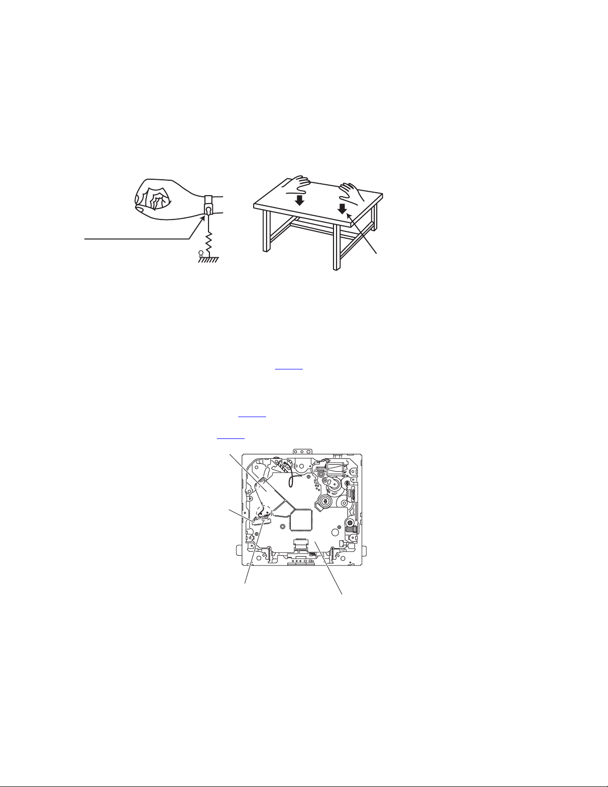
(1) Ground the workbench
Ground the workbench by laying conductive material (such as a conductive sheet) or an iron plate over it before placing the
traverse unit (optical pickup) on it.
(2) Ground yourself
Use an anti-static wrist strap to release any static electricity built up in your body.
(caption)
Anti-static wrist strap
1M
Conductive material
(conductive sheet) or iron plate
(3) Handling the optical pickup
• In order to maintain quality during transport and before installation, both sides of the laser diode on the replacement optical
pickup are shorted. After replacement, return the shorted parts to their original condition.
(Refer to the text.)
• Do not use a tester to check the condition of the laser diode in the optical pickup. The tester's internal power source can easily
destroy the laser diode.
1.3 Handling the traverse unit (optical pickup)
(1) Before disconnecting the flexible wire from the connector CN101
on the flexible wire.
Caution:
If you do not follow this instruction, the DVD pickup may be damaged.
(2) Disconnect the flexible wire from the connector CN101
(3) Remove the solders from the short-circuit points on the flexible wire after replacing the DVD pickup.
(4) Connect the flexible wire to the connector CN101
Flexible wire
CN101
on the mechanism control board.
on the mechanism control board.
on the mechanism control board, solder the short-circuit points
1-4 (No.MA149)
Short-circuit points
Mechanism control board
Page 5

SECTION 2
SPECIFIC SERVICE INSTRUCTIONS
This service manual does not describe SPECIFIC SERVICE INSTRUCTIONS.
(No.MA149)1-5
Page 6
SECTION 3
DISASSEMBLY
3.1 Main body section
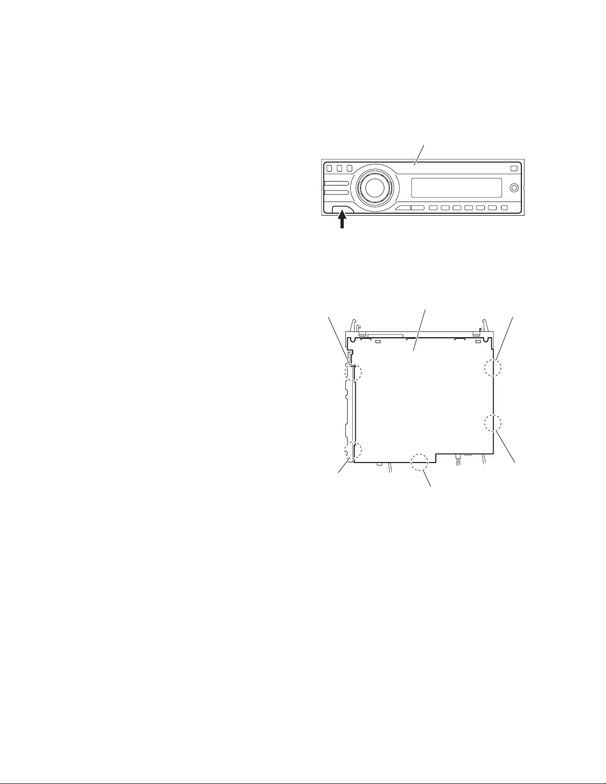
3.1.1 Removing the front panel assembly
(See Fig.1)
Push the detach button in the lower left part of the front panel assembly and remove the front panel assembly.
3.1.2 Removing the bottom cover
(See Fig.2)
Reference:
Remove the front panel assembly as required.
(1) Release the two joints a, two joints b and joint c.
(2) Remove the bottom cover from the main body.
Caution:
Do not damage the main board when releasing the joints using
a screwdriver or a similar tool.
Detach button
b
Front panel assembly
Fig.1
Bottom cover
a
a
b
c
Fig.2
1-6 (No.MA149)
Page 7
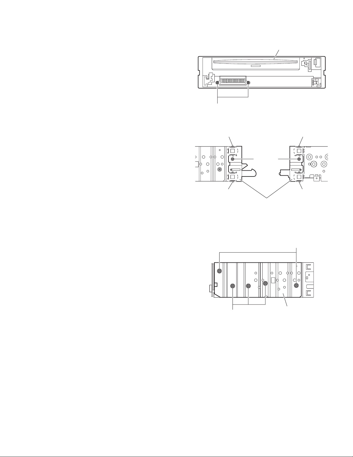
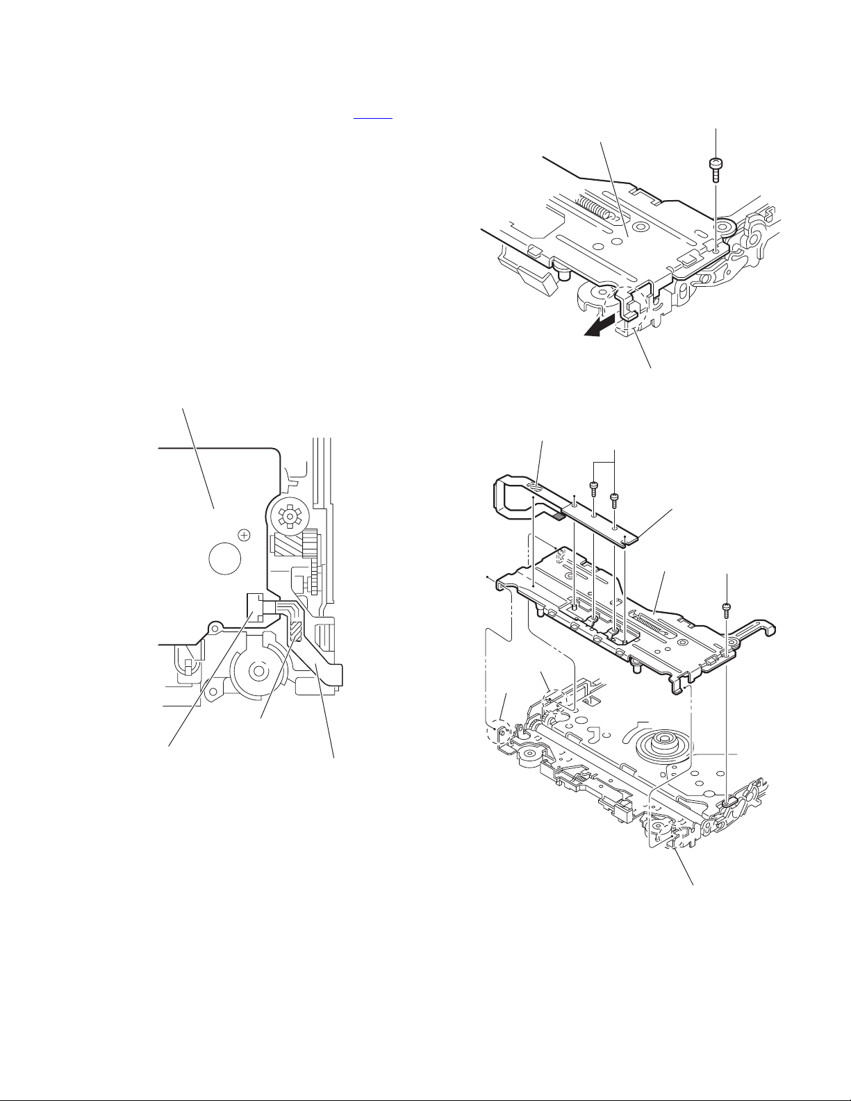
3.1.3 Removing the front chassis assembly
(See Figs.3 and 4)
• Remove the front panel assembly and bottom cover.
(1) From the front side of the main body, remove the two
screws A attaching the front chassis assembly. (See
Fig.3.)
(2) From the both sides of the main body, remove the two
screws B attaching the front chassis assembly. (See
Fig.4.)
(3) Release the two joints d and two joints e. (See Fig.4.)
Front chassis assembly
A
Fig.3
3.1.4 Removing the side heat sink
(See Fig.5)
Reference:
Remove the front panel and front chassis assemblies as re-
quired.
From the left side of the main body, remove the two screws C and
three screws D attaching the side heat sink.
d
B
d
Front chassis assembly
Fig.4
e
B
e
C
D
Side heat sink
Fig.5
(No.MA149)1-7
Page 8
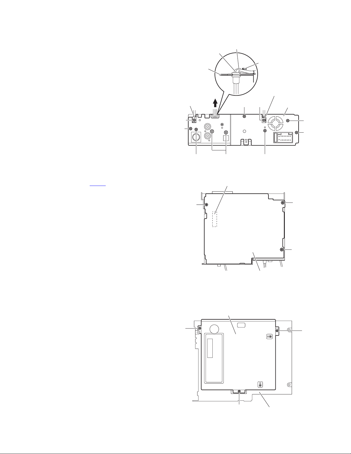
3.1.5 Removing the rear bracket
(See Fig.6)
• Remove the bottom cover.
(1) From the back side of the main body, remove the two
screws E, two screws E', screw F, two screws G and three
screws H attaching the rear bracket.
(2) Remove the LINE IN cable from the rear bracket in the di-
rection of the arrow.
Reference:
• When attaching the LINE IN cable, insert it in a slot of the
rear bracket and hang it on a wire holder.
• When attaching the screws E', attach the cable holders with
them.
LINE IN cable
Rear bracket
Cable holder
Slot
Wire holder
HEE'
Cable holder
Rear bracket
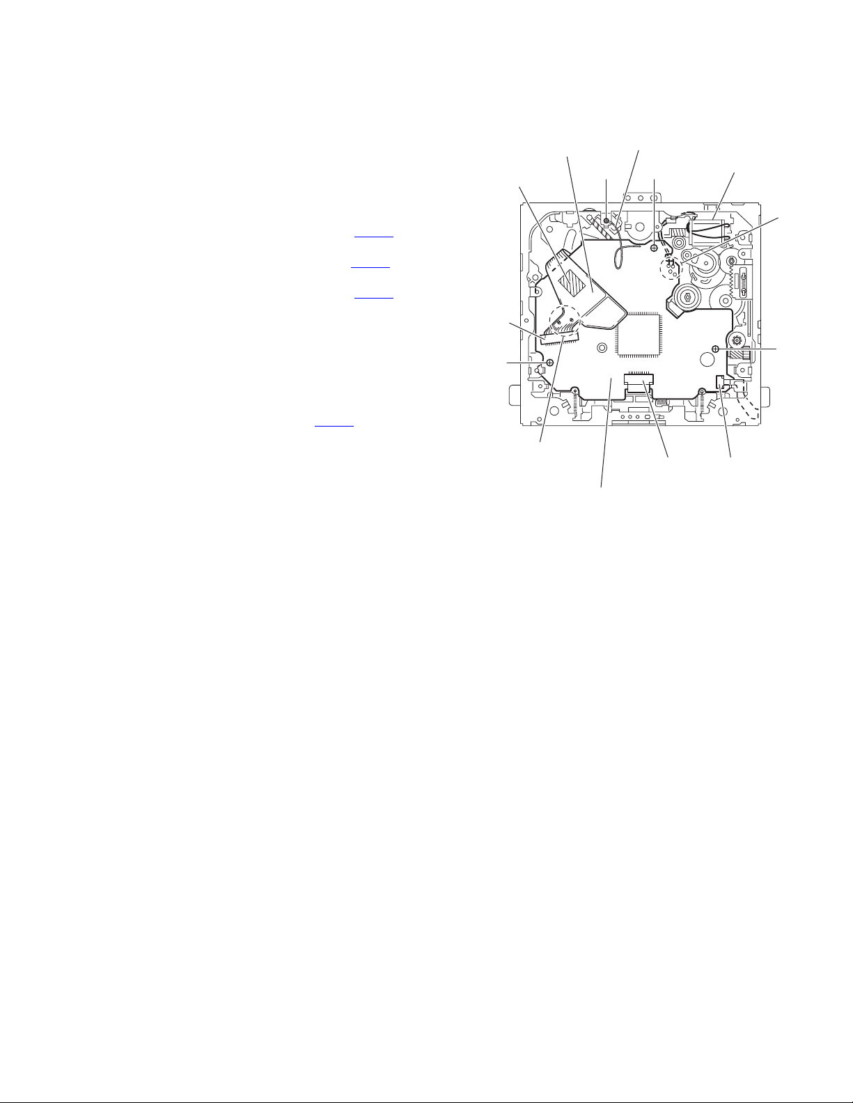
3.1.6 Removing the main board
(See Figs.6 and 7)
• Remove the front panel assembly, bottom cover, front chassis
assembly and side heat sink.
Reference:
Remove the rear bracket as required.
(1) From the back side of the main body, remove the three
screws H attaching the main board. (See Fig.6.)
(2) From the bottom side of the main body, remove the three
screws J attaching the main board. (See Fig.7.)
(3) Disconnect the connector CN961
the DVD mechanism assembly and take out the main
board from the main body. (See Fig.7.)
3.1.7 Removing the DVD mechanism assembly
(See Fig.8)
• Remove the front panel assembly, bottom cover, front chassis
assembly, side heat sink and main board.
(1) From the inside of the top chassis, remove the three
screws K attaching the DVD mechanism assembly.
(2) Take out the DVD mechanism assembly from the top chas-
sis.
on the main board from
E'
H
K
F
G
CN961
J
DVD mechanism assembly
E
H
Fig.6
J
J
Main board
Fig.7
K
1-8 (No.MA149)
K
Fig.8
Top chassis
Page 9
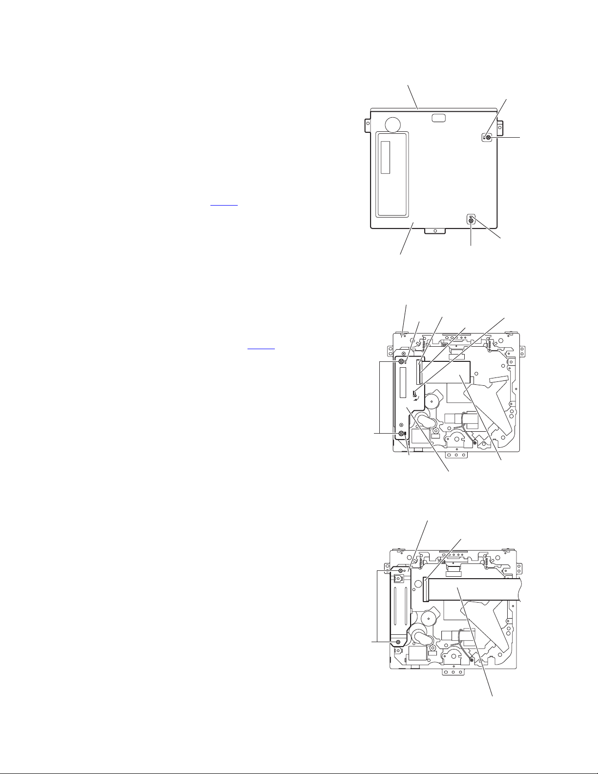
3.1.8 Removing the main sub board
(See Figs.9 to 11)
• Remove the front panel assembly, bottom cover, front chassis
assembly, side heat sink, main board and DVD mechanism assembly.
(1) From the top side of the DVD mechanism assembly, re-
move the two screws L attaching the dust cover. (See
Fig.9.)
(2) Remove the dust cover from the DVD mechanism assem-
bly. (See Fig.9.)
Reference:
When attaching the dust cover, align the joints f in the
holes of the dust cover before attaching the screws L.
(See Fig.9.)
(3) Release the lock of the connector CN962
board and disconnect the card wire. (See Fig.10.)
(4) Bend the joint g in the direction of the arrow. (See Fig.10.)
(5) Remove the two screws M attaching the main sub board
and remove the main sub board from the DVD mechanism
assembly. (See Fig.10.)
Reference:
• When attaching the main sub board, align the joints h in the
holes of the main sub board before attaching the screws M.
(See Fig.10.)
• When the resolution of DVD mechanism assembly is done
sequentially, remove the two screws N attaching the support
bracket. (See Fig.11.)
• Remove the card wire from the connector CN401
quired. (See Fig.11.)
on the main sub
as re-
DVD mechanism assembly
Dust cover
Fig.9
DVD mechanism assembly
CN962
h
f
L
f
L
g
Lock
M
N
h
Main sub board
Fig.10
Support bracket
CN401
Fig.11
Card wire
Card wire
(No.MA149)1-9
Page 10
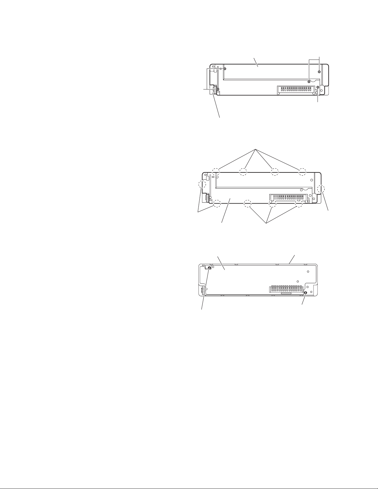
3.1.9 Removing the switch board
(See Figs. 12 to 14)
• Remove the front panel assembly.
(1) From the back side of the front panel assembly, remove the
five screws P attaching the rear cover. (See Fig.12.)
(2) Release the ten joints i attaching the rear cover to the front
panel assembly. (See Fig.13.)
(3) Take out the switch board while lifting the switch board
from the front panel assembly little by little. (See Fig.14.)
Reference:
Remove the volume knob from the front side of the front panel
assembly at the same time.
Note:
Do not lose the compression springs when removing the
switch board. (See Fig.14.)
Rear cover
P
Front panel assembly
P
P
Fig.12
i
i
Rear cover
Switch board
Compression spring
i
i
Fig.13
Front panel assembly
Compression spring
Fig.14
1-10 (No.MA149)
Page 11
3.2 DVD mechanism assembly
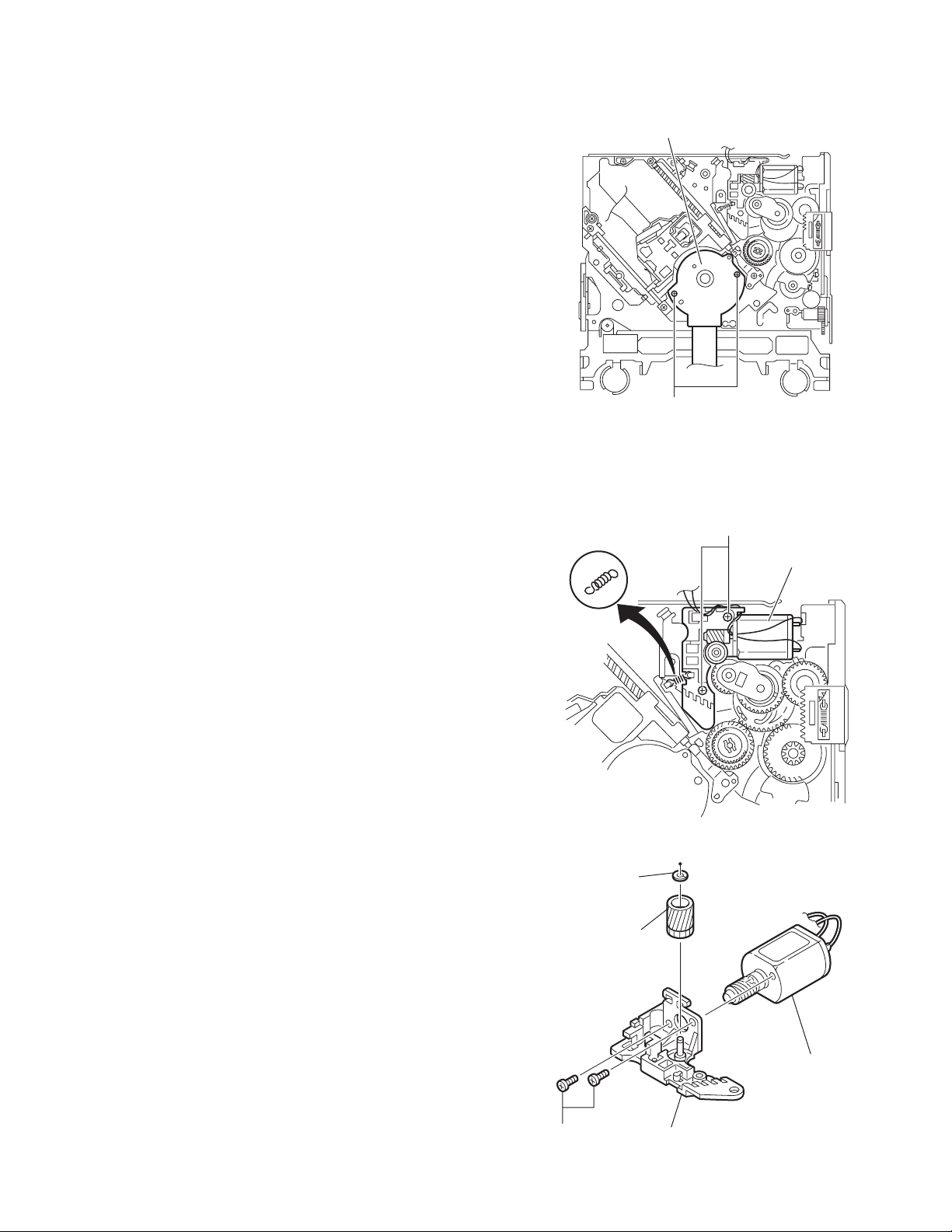
3.2.1 Removing the mechanism control board
(See Fig.1)
Caution:
Before disconnecting the flexible wire extending from the DVD
pickup, solder the short-circuit point on the flexible wire using
a grounding soldering iron. If you do not follow this instruction,
the DVD pickup may be damaged.
(1) Turn over the body, and solder the short-circuit points on
the flexible wire extending from the DVD pickup.
(2) Disconnect the flexible wire from connector CN101
mechanism control board.
(3) Disconnect the card wire from connector CN201
mechanism control board.
(4) Disconnect the flexible wire from connector CN202
mechanism control board.
(5) Unsolder two soldered points a on the mechanism control
board and remove the wire extending from the feed motor.
(6) Remove the screw A attaching the lug wire.
(7) Remove the two screws B and screw C attaching the
mechanism control board.
Caution:
• As the flexible wire to be connected to CN101
attach it to the mechanism control board using a double
tape.
• After reassembling, unsolder the short-circuit points.
on the
on the
on the
, make sure to
Flexible wire
Double tape
CN101
B
Short-circuit points
A
Lug wire
B
CN201
Feed motor
a
C
CN202
Mechanism control board
Fig.1
(No.MA149)1-11
Page 12
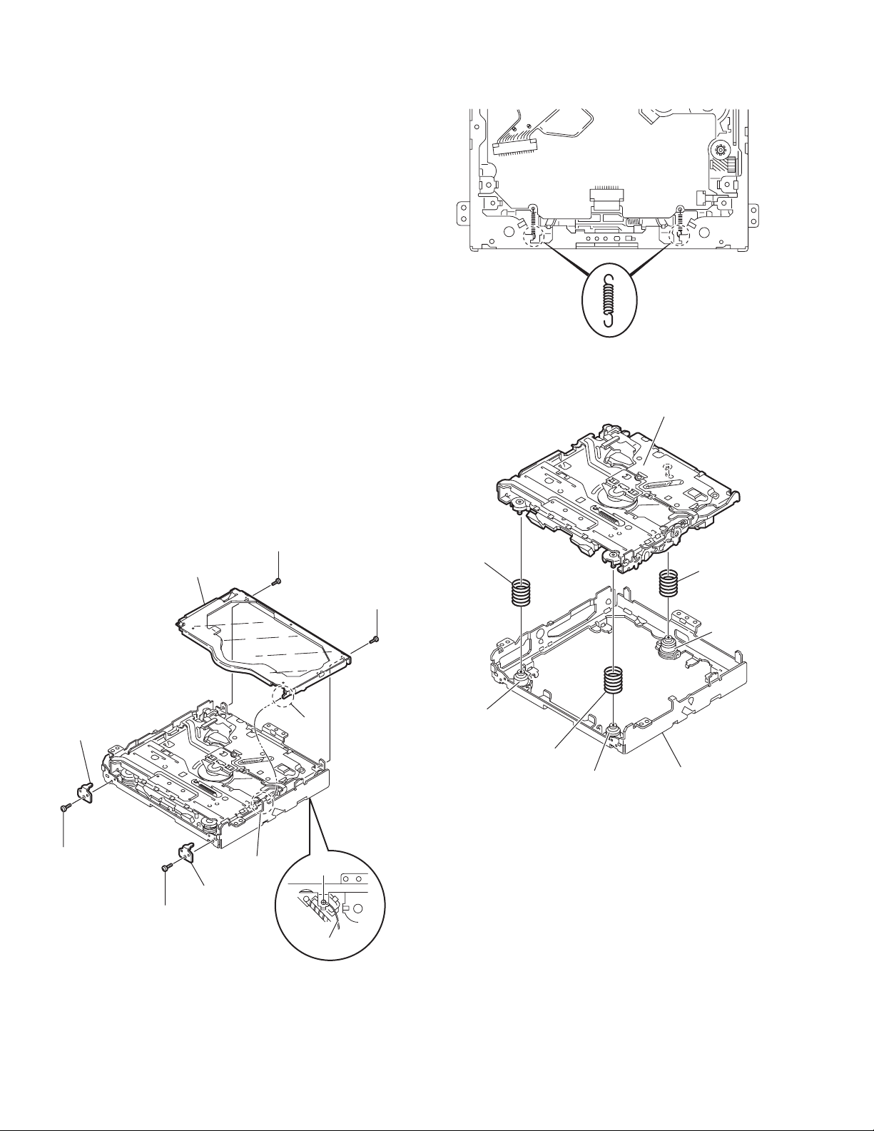
3.2.2 Removing the top cover
(See Fig.2)
(1) Remove the two screws D attaching the top cover on the
back of the body.
(2) Remove the top cover upward.
Reference:
When reassembling, set part b of the top cover under the
bending part c of the chassis frame.
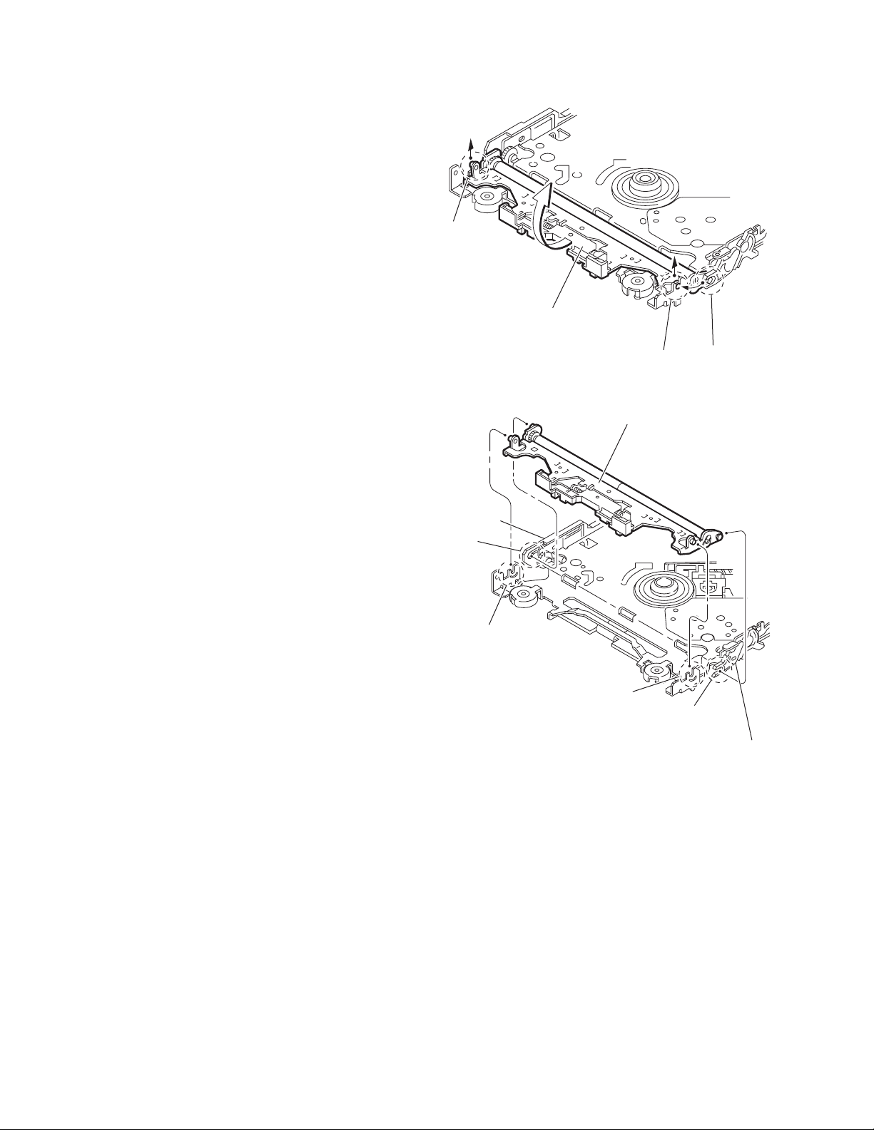
3.2.3 Removing the mechanism section
(See Fig.2 to 4)
• Remove the top cover.
(1) From the bottom of the body, remove the screw E attaching
the lug wire. (See Fig.2.)
(2) Remove the two screws F attaching the right and left stop-
pers on the front side. (See Fig.2.)
(3) Remove the two floating springs on the bottom of the body.
(See Fig.3.)
(4) Move the mechanism section upward and remove from the
chassis frame.
The three damper springs come off from the dampers.
(See Fig.4.)
Caution:
• When reassembling, reattach the damper spring to the
damper respectively and insert the three shafts on the bottom of the mechanism to the dampers.
• Before inserting the shaft to the dampers, apply IPA to the
hole of damper.
Floating spring
Fig.3
Mechanism section
Stopper
F
Top cover
Stopper
F
D
D
b
c
E
Lug wire
Damper SP.(F)
(Silver)
Damper (F)
(Black)
Damper SP.(F)
(Silver)
Damper (F)
(Black)
Fig.4
Damper SP.(R)
(Red)
Damper (R)
(Purple)
Chassis frame
1-12 (No.MA149)
Fig.2
Page 13
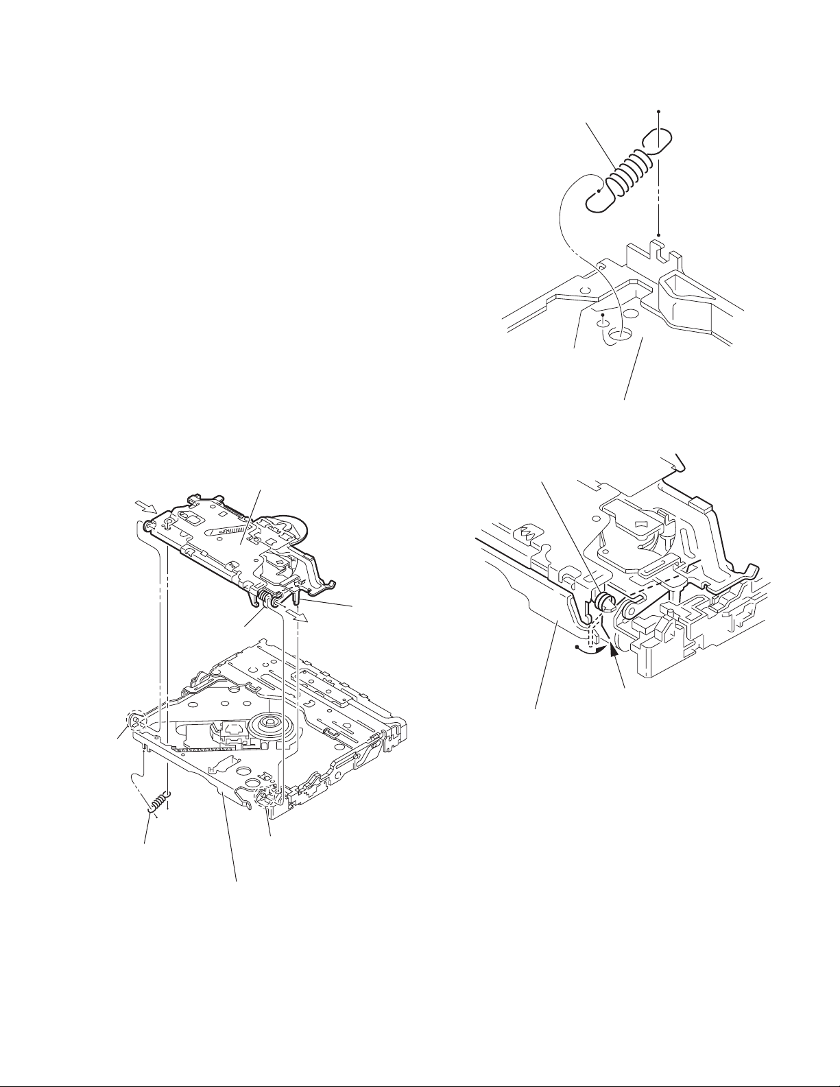
3.2.4 Removing the clamper unit
(See Fig.5 to 7)
• Remove the top cover and the mechanism section.
(1) Remove the clamper2 spring on the bottom of the mecha-
nism section. (See Figs.5.and 6.)
(2) Release the part d of the clamper spring from the bending
part of the chassis base assembly. (See Fig.7.)
(3) Move the clamper unit in the direction of the arrow and turn.
Release the two joints e and f, then remove the clamper
unit upward. (See Fig.6.)
3.2.5 Reattaching the clamper unit
(See Fig.5 to 9)
(1) Attach the clamper spring to the clamper unit. (See Fig.8.)
(2) Move the clamper unit to set the side joints e and f to each
boss of the chassis base assembly. Make sure that part g
is inserted to the notch of the chassis base assembly. (See
Figs.5 and 9.)
(3) Move the part d of the clamper spring to the outside of the
bending part of the chassis base assembly. (See Fig.7.)
(4) Attach the clamper2 spring to the chassis base assembly.
(See Figs.5 and 6.)
Caution:
When reattaching, temporarily hook the end of the clamper
spring as shown in the figure to make the work easy. (See
Fig.8.)
Clamper unit
Clamper2 spring
Chassis base assembly
Fig.6
Clamper spring
Clamper spring
f
Clamper2 spring
Chassis base assembly
g
d
Chassis base assembly
Fig.7
e
Fig.5
(No.MA149)1-13
Page 14
Clamper unit
Clamper unit
Clamper spring
Fig.8
1-14 (No.MA149)
Fig.9
g
Notch
Page 15
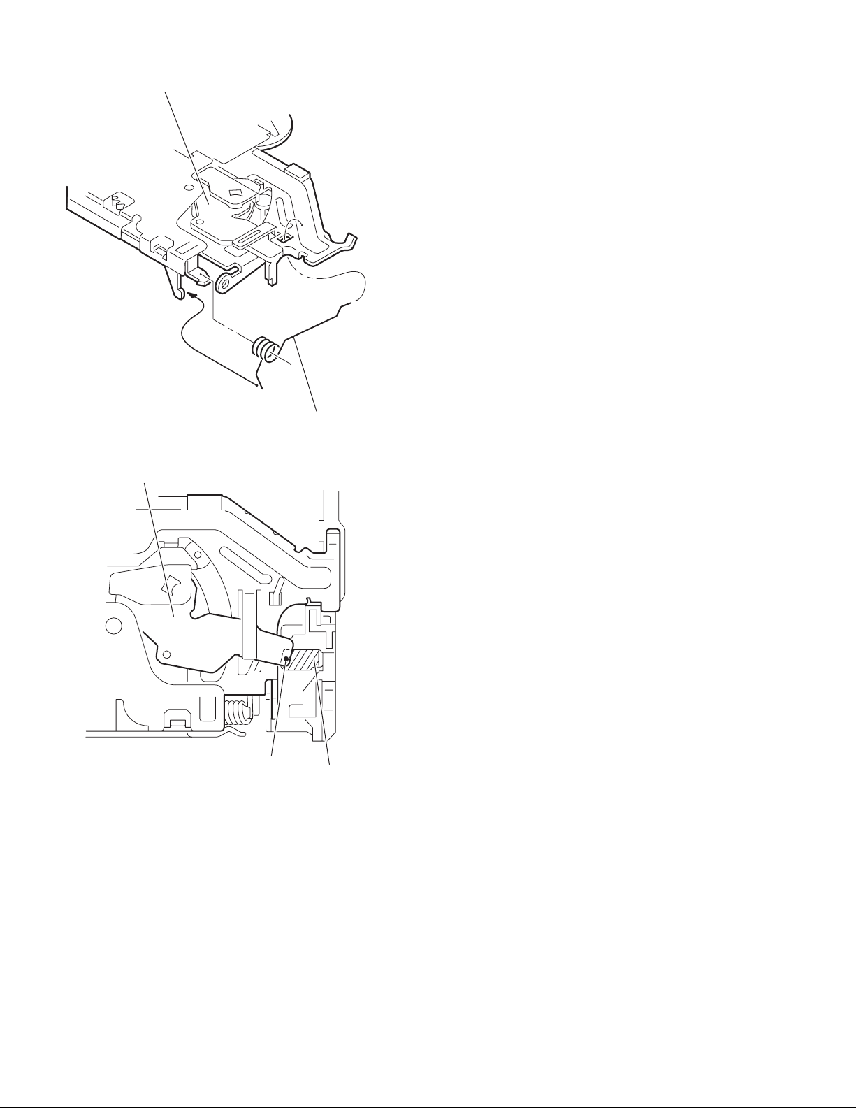
3.2.6 Removing the front unit
(See Fig.10 to 12)
• Remove the top cover and the mechanism section.
(1) Disconnect the flexible wire from connector CN202
mechanism control board at the bottom of the body. (See
Fig.10.)
(2) Remove the screw G attaching the front unit on the top of
the body. (See Fig.11.)
(3) Move the front unit toward the front to release joint h, and
release two joints i and j on the right side of the chassis
base assembly. Then remove the front unit upward. (See
Figs.11 and 12.)
(4) Remove the two screws H attaching the switch board. (See
Fig.12.)
Reference:
You can remove the switch board only without removing the
front unit.
Caution:
When reassembling, attach the flexible wire extending from
the switch board using the double tape. (See Figs.10 and 12.)
Mechanism control board
on the
G
Front unit
h
Fig.11
CN202
Double tape
Fig.10
Flexible wire
Double tape
j
i
H
Switch board
Front unit
G
Fig.12
h
(No.MA149)1-15
Page 16
3.2.7 Removing the loading arm assembly
(See Fig.13 , 14)
• Remove the top cover, the mechanism section and the front
unit.
(1) From the top of the body, move the loading arm assembly
from the front side upward, and release the bosses from
the right and left joints k and m of the chassis base assembly.
(2) Release the boss from notch n of the connect arm on the
right side of the body, and release the boss from notch p of
the slide cam assembly on the left side.
m
Loading arm assembly
Side cam
assembly
p
m
k
Fig.13
Loading arm assembly
k
n
n
Connect arm
1-16 (No.MA149)
Fig.14
Page 17
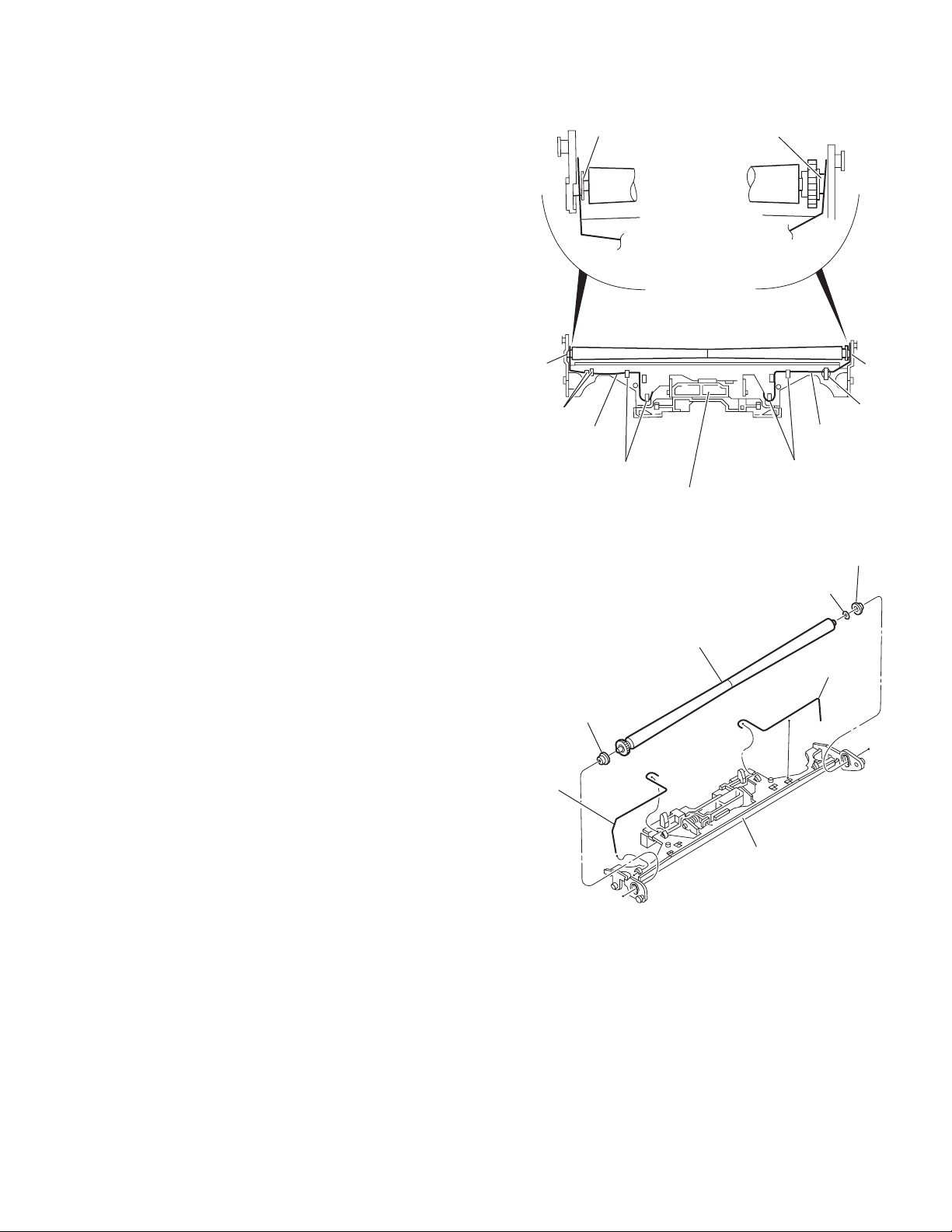
3.2.8 Removing the rod (L)(R)/roller assembly
(See Fig.15 and 16)
• Remove the top cover, the mechanism section, the front unit
and the loading arm assembly.
(1) Release the rod (L) and (R) from the joints q at the bottom
of the loading arm assembly (See Fig.15.)
(2) Remove the roller assembly from the loading arm assem-
bly. (See Fig.16.)
(3) Remove the two collars and washer from the roller assem-
bly. (See Fig.16.)
Caution:
After attaching the loading arm assembly to the roller assembly, attach the rod (L) and (R). Attach the rods to the right and
left collars of the roller. (See Fig.15.)
When reattaching the rod (L) and (R) to the loading arm assembly, engage each joint as shown in Fig.15. As joints q of
the rod (L), let the rod through q before reattaching it.
Collar
Collar
Rod(R) Rod(L)
q
q
q
Collar
Rod(L)
Rod(R)
q
Loading arm assembly
Fig.15
Roller assembly
Loading arm assembly
q
Rod(L)
q
Collar
Washer
Rod(R)
Fig.16
(No.MA149)1-17
Page 18
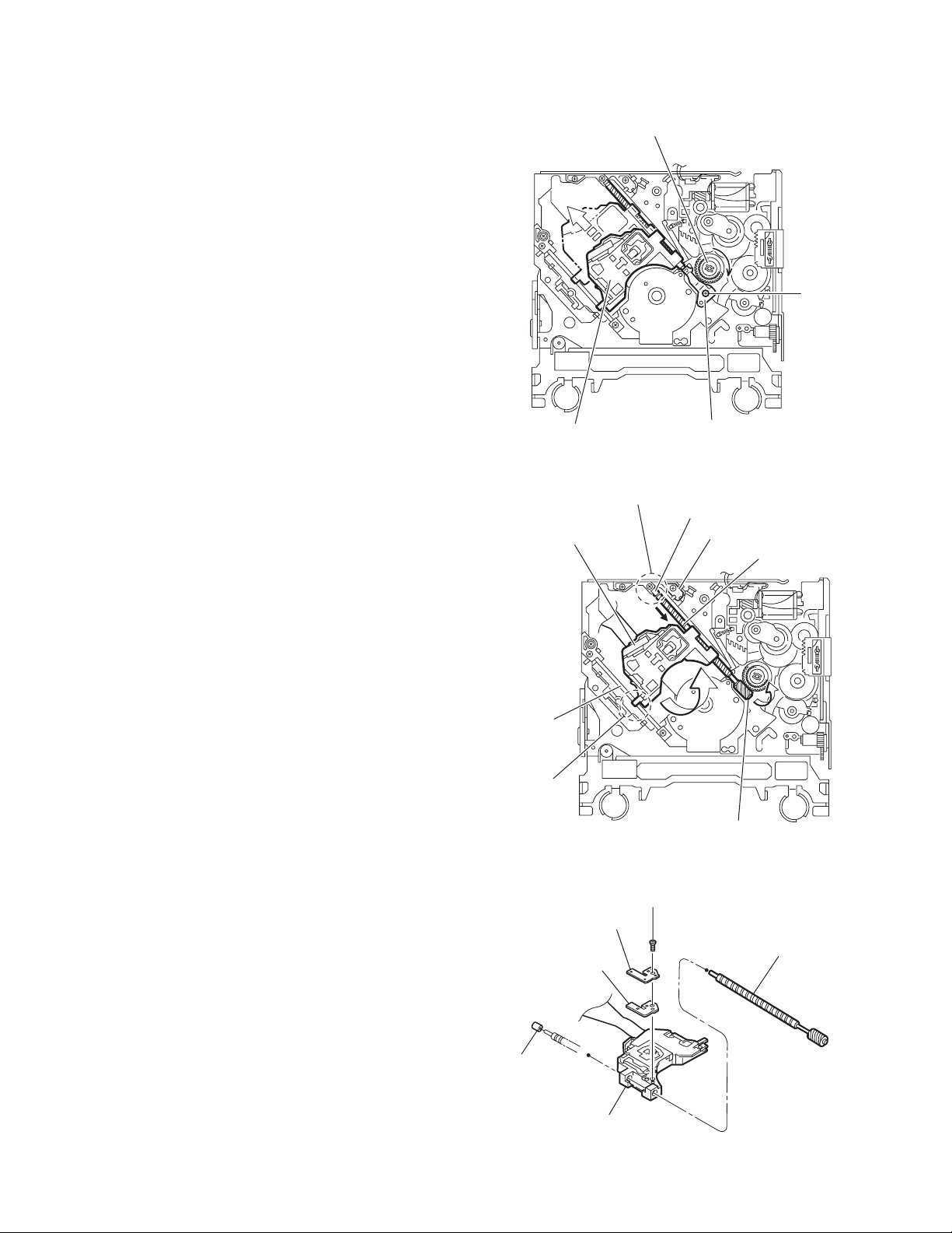
3.2.9 Removing the DVD pickup assembly
(See Fig.17 to 19)
• Remove the mechanism control board.
(1) From the bottom of the body, turn the feed gear in the di-
rection of the arrow to move the DVD pickup outwards.
(See Fig.17.)
(2) Remove the screw J attaching the thrust spring. (See
Fig.17.)
(3) Remove the DVD pickup assembly upward on the L.S.gear
side and release from sub shaft at joint r. Move the lead
screw of the DVD pickup assembly in the direction of the
arrow to release from joint s. (See Fig.18.)
Caution:
• When releasing the lead screw at joint s, the L.S.collar
comes off at the end of the lead screw. When reassembling, reattach the L.S.collar to the lead screw and
engage joint s. (See Fig.18.)
• When reattaching the L.S.collar, reattach it to the point
s of the lead screw, and to the rod (M). Make sure that
the L.S.collar is set on the rod (M) spring. (See Fig.18.)
(4) Remove the screw K attaching the rack spring/ rack plate
on the DVD pickup. (See Fig.19.)
(5) Pull out the lead screw. (See Fig.19.)
Caution:
Perform adjustment after replacing the pickup.
DVD Pickup assembly
DVD Pickup assembly
Feed gear
J
Thrust spring
Fig.17
s
L.S.collar
Rod(M)
Lead screw
Sub shaft
L.S.collar
r
L.S.gear
Fig.18
K
Rack spring
Lead screw
Rack plate
DVD Pickup
Fig.19
1-18 (No.MA149)
Page 19
3.2.10 Removing the spindle motor
r
(See Fig.20)
• Remove the mechanism control board.
Remove the two screws L attaching the spindle motor on the
bottom of the body.
Caution:
Perform adjustment when reattaching the spindle motor.
3.2.11 Removing the feed motor assembly
(See Fig.21 and 22)
• Remove the mechanism control board.
(1) Remove the feed TRI. spring on the bottom of the body.
(See Fig.21.)
(2) Remove the two screws M attaching the feed motor as-
sembly. (See Fig.21.)
(3) Remove the slit washer from the motor H. assembly and
pull out the worm wheel. (See Fig.22.)
Remove the two screws N attaching the feed motor. (See
Fig.22.)
Spindle motor
Feed TRI. spring
L
Fig.20
M
Feed motor assembly
Fig.21
Slit washer
Worm wheel
Feed moto
N
Motor H. assembly
Fig.22
(No.MA149)1-19
Page 20
SECTION 4
ADJUSTMENT
4.1 Test instruments required for adjustment
(1) Digital oscilloscope (100MHz)
(2) Jitter meter
(3) Digital tester
(4) Electric voltmeter
(5) Tracking offset meter
(6) Test Disc : VT501 or VT502
(7) Extension studs : STDV001-3P
(8) Extension cable : EXTDV002-30P
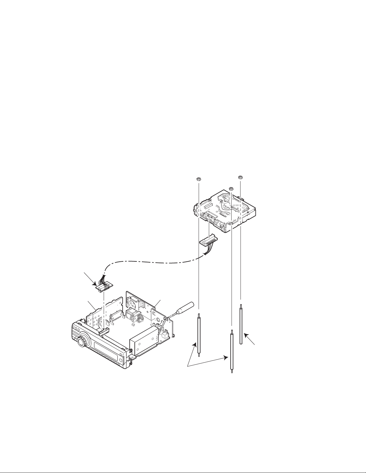
4.3 Connection method
Connection procedure
(1) Attach the front chassis assembly to the main board.
(2) Connect the front panel assembly to the main board.
(3) Attach the heat sink and rear bracket to the main board.
(4) Attach the extension studs to the DVD mechanism assembly.
(5) Connect the DVD mechanism assembly and the main board with a extension cable.
4.2 Standard measuring conditions
Power supply voltage DC14.4V(11 to 16V)
Load impedance 4Ω(2 Speakers connection)
Line Output 20KΩ
Caution:
Be sure to attach the heat sink and rear bracket onto the power
amplifier IC and regulator IC respectively, before supply the
power. If voltage is applied without attaching these parts, the
power amplifier IC and regulator IC will be destroyed by heat.
Extension cable
EXTDV002-30P
Heat sink
Rear bracket
Main board
Extension stud
STDV001-3P
Extension studs
STDV001-3P
1-20 (No.MA149)
Page 21

After replacing the pickup, set the unit in the service mode to display a jitter value on the LCD. Confirm that the jitter value measured
with a jitter meter is within 12% of the jitter value displayed on the LCD. If it is within 12%, then adjustment is not necessary. Please
note that a jitter value displayed on the LCD is hex data. Refer to the corresponding decimal notation value using the Jitter Conversion
Table and confirm it with the measured value.
Fix the screws "a", "b" and "c" with screw lock paint.
If the measured jitter value is outside the 12% tolerance range, perform the following adjustments.
c
b
a
Jitter value adjustment procedure (Pickup horizontal level adjustment relative to the DVD recording surface)
(For the adjustment tool use a 3 mm wrench and not a screwdriver, this procedure will make the adjustment easier.)
3 mm wrench
(1) Set the unit to the service mode and display a jitter value (hex data) on the LCD.
(2) Turn each of the screws a, b and c, by a half-turn per step, in the direction that reduces the jitter value in order to minimize it.
(Do not turn a screw more than a half turn at a time, but adjust the screws in the cycle of a
(3) After completing the adjustment, secure the screws with screw lock paint.
→ b → c → d → a.)
(No.MA149)1-21
Page 22

4.4 Jitter value conversion table
Load the test DVD and set the unit to the service mode. A jitter value converted to the hex value is displayed on the LCD. Refer to the
corresponding decimal notation value shown in the following Jitter Conversion Table.
The adjustment is OK if the jitter value measured with a jitter meter is within 12% of the jitter value displayed on the LCD.
If the measured jitter value is outside the 12% tolerance range, adjust it to minimize the difference between the measured value and
the displayed value.
Indicated
on the LCD
20A7
2072
203D
2008
1FD2
1F9D
1F68
1F33
1EFE
1EC8
1E93
1E5E
1E29
1DF4
1DBE
1D89
1D54
1D1F
1CEA
1CB4
1C7F
1C4A
1C15
1BE0
1BAA
1B75
1B40
1B0B
1AD6
1AA0
1A6B
1A36
1A01
19CC
1996
1961
192C
18F7
JIT OUT
1957.98
1955.32
1952.66
1950
1947.34
1944.68
1942.02
1939.36
1936.7
1934.04
1931.38
1928.72
1926.06
1923.4
1920.74
1918.08
1915.42
1912.76
1910.1
1907.44
1904.78
1902.12
1899.46
1896.8
1894.14
1891.48
1888.82
1886.16
1883.5
1880.84
1878.18
1875.52
1872.86
1870.2
1867.54
1864.88
1862.22
1859.56
Jitter value
(%)
4.7
3818
4.8
3825
4.9
3832
5.0
3840
5.1
384D
5.2
385A
5.3
3867
5.4
3875
5.5
3882
5.6
388F
5.7
389D
5.8
38AA
5.9
38B7
6.0
38C5
6.1
38D2
6.2
38DF
6.3
38EC
6.4
38FA
6.5
3907
6.6
3914
6.7
3922
6.8
392F
6.9
393C
7.0
394A
7.1
3957
3964
7.2
3971
7.3
397F
7.4
398C
7.5
3999
7.6
39A7
7.7
39B4
7.8
39C1
7.9
39CF
8.0
39DC
8.1
39E9
8.2
39F6
8.3
3A04
8.4
Indicated
on the LCD
18C2
188C
1857
1822
17ED
17B8
1782
174D
1718
16E3
16AE
1678
1643
160E
15D9
15A4
156E
1539
1504
14CF
149A
1464
142F
13FA
13C5
1390
135A
1325
12F0
12BB
1286
1250
121B
11E6
11B1
117C
1146
1111
JIT OUT
1856.9
1854.24
1851.58
1848.92
1846.26
1843.6
1840.94
1838.28
1835.62
1832.96
1830.3
1827.64
1824.98
1822.32
1819.66
1817
1814.34
1811.68
1809.02
1806.36
1803.7
1801.04
1798.38
1795.72
1793.06
1790.4
1787.74
1785.08
1782.42
1779.76
1777.1
1774.44
1771.78
1769.12
1766.46
1763.8
1761.14
1758.48
Jitter value
(%)
3A11
8.5
3A1E
8.6
3A2C
8.7
3A39
8.8
3A46
8.9
3A54
9.0
3A61
9.1
3A6E
9.2
3A7B
9.3
3A89
9.4
3A96
9.5
3AA3
9.6
3AB1
9.7
3ABE
9.8
3ACB
9.9
3AD9
10.0
3AE6
10.1
3AF3
10.2
3B00
10.3
3B0E
10.4
3B1B
10.5
3B28
10.6
3B36
10.7
3B43
10.8
3B50
10.9
3B5E
11.0
3B6B
11.1
3B78
11.2
3B85
11.3
3B93
11.4
3BA0
11.5
3BAD
11.6
3BBB
11.7
3BC8
11.8
3BD5
11.9
3BE3
12.0
3BF0
12.1
3BFD
12.2
Indicated
on the LCD
10DC
10A7
1072
103C
1007
FD2
F9D
F68
F32
EFD
EC8
E93
E5E
E28
DF3
DBE
D89
D54
D1E
CE9
CB4
C7F
C4A
C14
BDF
BAA
B75
B40
B0A
AD5
AA0
A6B
A36
A00
9CB
996
961
92C
JIT OUT
1755.82
1753.16
1750.5
1747.84
1745.18
1742.52
1739.86
1737.2
1734.54
1731.88
1729.22
1726.56
1723.9
1721.24
1718.58
1715.92
1713.26
1710.6
1707.94
1705.28
1702.62
1699.96
1697.3
1694.64
1691.98
1689.32
1686.66
1684
1681.34
1678.68
1676.02
1673.36
1670.7
1668.04
1665.38
1662.72
1660.06
1657.4
Jitter value
(%)
12.3
3C0A
12.4
3C18
12.5
3C25
12.6
3C32
12.7
3C40
12.8
3C4D
12.9
3C5A
13.0
3C68
13.1
3C75
13.2
3C82
13.3
3C8F
13.4
3C9D
13.5
3CAA
13.6
3CB7
13.7
3CC5
13.8
3CD2
13.9
3CDF
14.0
3CED
14.1
3CFA
14.2
3D07
14.3
3D14
14.4
3D22
14.5
3D2F
14.6
3D3C
14.7
3D4A
14.8
3D57
3D64
14.9
3D72
15.0
3D7F
15.1
3D8C
15.2
3D99
15.3
3DA7
15.4
3DB4
15.5
3DC1
15.6
3DCF
15.7
3DDC
15.8
3DE9
15.9
3DF7
16.0
1-22 (No.MA149)
Page 23

4.5 Service mode
4.5.1 Standard input/output conditions
Power supply voltage DC14.4V(11 to 16V)
Load impedance 4Ω(2 Speakers connection)
Line Output 20KΩ
4.5.2 Service mode setting procedure
(The DVD does not need to be loaded before starting the following procedure.)
[SEL] button
[STANDBY/ON ATTENUATOR] button
[DISC UP] button
[DISC DOWN] button
(1) Press a [STANDBY/ON ATTENUATOR] button on a main unit and switch it on.
(2) Keep this state more than 2 seconds while continuing pressing the [SEL] button, [STANDBY/ON ATTENUATOR] button and
[SOURCE] button sequentially.
(3) This unit is set by a service mode.
*Exchanging it operate a menu of a service mode with the [DISC UP] button and [DISC DOWN] button.
Operate choice of a menu with a [SEL] button.
[SOURCE] button
(No.MA149)1-23
Page 24

4.5.3 Operation procedures
Keep this state more than 2 seconds while
continuing pressing the [SEL] button,
[STANDBY/ON ATTENUATOR] button and
[SOURCE] button sequentially.
The unit enters the service mode.
"INIT ALL" is
indicated on the LCD.
"VERSION" is
indicated on the LCD.
"AREA/RGN" is
indicated on the LCD.
"VIDEO" is
indicated on the LCD.
Press the [SEL] key
Press the [SEL] key
Press the [SEL] key
Press the [SEL] key
Initialize all data to the factory setting
: The system control EEPROM is initialized entirely.
Microcomputer version display
************
************
Exchanging it operate each indication with the
[DISC UP] button and [DISC DOWN] button.
Destination area/region display
************
************
************
Exchanging it operate each indication with the
[DISC UP] button and [DISC DOWN] button.
Setting of NTSC or PAL
"NTSC" or "PAL" are indicated on the LCD.
Exchanging it operate each indication with the
[DISC UP] button and [DISC DOWN] button.
System control microcomputer version
DVD version
System control destination
DVD unit destination
DVD unit region
Note:
There is the model that is not equipped with
this mode by a version.
A B
1-24 (No.MA149)
"CLR ERR" is
indicated on the LCD.
Press the [SEL] key
Clear loading/ejection error history
: The error history stored in the EEPROM is cleared.
Page 25

A B
"CD ERROR" is
indicated on the LCD.
Frror code (1 byte)
First byte [01] Eject error
Detailed error codes (2 bytes) Displayed with loading/ejection errors only.
First byte
Second byte
Press the [SEL] key
Read loading and ejection error history
: The error history saved in the system control
is read and displayed.
TOT-xxxx : Total error count.
Total error count
(A figure between 0 and 9999 is
displayed. 10000 or more is also
displayed as 9999.)
Enyyzzzz : Latest three error codes.
Detailed error code
Error code
Counter
0nyyzzzz : First five error codes
Detailed error code
Error code
Counter
Exchanging it operate each indication with the
[DISC UP] button and [DISC DOWN] button.
[09] Loading error
Higher 4 bits
Lower 4 bits
[1] Time out
[2] Switch status error
[3] Swinging error
bit7
bit6,5
bit4
bit3
bit2
bit1
bit0
(Example) When a switch status error occurs during loading route 3 and
the switch status is L/L/H/H/H (00111B = 07H), the error code
and detailed error code become: [09 3207].
Route No. (EJECT route No.)
-
1(2)
1(2)
Route No. (Process of error occurrence)
Refer to charts 1.1 and 1.2.
Error type
Disc type (0: 12 cm. 1: 8 cm)
Fixed at 0
SW1 status
SW2 status
SW3 status
SW4 status
REST SW status
SW1/2/3/4
1,1,1,1
0,1,1,1
0,0,1,1
[Rest SW]
[0]
[0]
[0]
Loading
No Disc
Disc insert
detection
Eject
No Disc
Eject
completion
Reload
Disc push in
C D
2(2)
2(2)
2(2)
2(2)
3(1)
3(1)
0,0,0,1
0,0,1,1
0,1,1,1
1,1,1,1
1,1,1,0
1,1,1,0
[0]
[0]
[0]
[0]
[0]
[1]
Load completion
Chart 1.1 12cm Disc switch status transition
Route No. (EJECT route No.)
-
1(2)
1(2)
2(2)
2(2)
3(1)
3(1)
Transition in the center loading (Similar to 12cm in the side loading)
SW1/2/3/4
1,1,1,1
0,1,1,1
0,0,1,1
0,1,1,1
1,1,1,1
1,1,1,0
1,1,1,0
[Rest SW]
[0]
[0]
[0]
[0]
[0]
[0]
[1]
Loading
No Disc
Disc insert
detection
Load completion
Chart 1.2 8cm Disc switch status transition
Eject start
Eject
No Disc
Eject
completion
Eject start
Reload start
Load completion
Reload
Disc push in
Reload start
Load completion
(No.MA149)1-25
Page 26

C D
"SYS-TEMP" is
indicated on the LCD.
"CHK MODE" is
indicated on the LCD.
"RUNNING" is
indicated on the LCD.
"MEMCHECK" is
indicated on the LCD.
"INIT" is
indicated on the LCD.
Press the [SEL] key
Press the [SEL] key
Press the [SEL] key
Press the [SEL] key
Press the [SEL] key
Thermistor's temperature data readout
: Data in the temperature sensor in the system control
is read every 5 seconds and displayed in hex numbers.
DVD unit check mode
(See section "5.1.4 DVD unit check mode" for details.)
Running mode: For use in running tests.
Memory check
: The remaining data capacity of the disc is displayed on the LCD.
Initialize user set data
: The system control EEPROM is initialized except for the
loading/ejection error history.
1-26 (No.MA149)
Page 27

4.5.4 DVD unit check mode
Change LCD indication with a [FF ] button and a [REW ] button.
Check item list
No. A/D key
[1]
1
[2]
2
[3]
3
[4]
4
[5]
5
[6]
6
[DISP]
7
[SOURCE]
8
[SEL]
9
[MODE]
10
[BAND]
11
[DISC UP ]
12
[DISC DW ]
13
[EJECT]
14
Start at normal speed
(After start, it is measured JITTER on the
internal position)
Tracking off on the outermost position of CD
Tracking off on the innermost position of CD
CD_LD lights and laser current is displayed
DVD_LD lights and laser current is displayed
DVD x1 jitter measuring mode
(for use in mechanism measurement)
Indication of EEPROM contents
Initialization of EEPROM contents
Indication of temperature
Search & jitter measurement to an appointed
position of DVD
Setting of MONITOR terminal
DVDx1 double speed start
(After start, it is measured JITTER on the
internal position)
Disc stopped & LD-OFF
OPEN
DVD unit operation
Example of
LCD indication
NORMPLAY
CUR
JIT
EF-BAL
OUTRKOFF
EF-BAL
INTRKOFF
CDLD ON
CUR
JIT
DVDLD ON
CUR
JIT
DVD JITR
CUR
JIT
ROM DATA
ADDR
DATA
ROMCLEAR
JD4-TEMP
TEM
DVD-DL
PLC
JIT
MONITOR
M1
M2
PLAY
CUR
JIT
STOP
DSC OPEN
Indication contents
Laser current value
Jitter value
For EF phase error
For EF phase error
Laser current value
Jitter value
Laser current value
Jitter value
Laser current value
Jitter value
EEPROM address
EEPROM contents
Temperature
(Position measured with VT-501)
Jitter value
Laser current value
Jitter value
Note
Press key [1] of No.1 before an item in which the No.2 or 3 key is pressed.
Press key [1] of No.1 or key [12] of No.12 before an item in which the No. 10 key is pressed and confirm
the indication of jitter value on the LCD.
No.6 starts only a DVD1 layer disk. Even other disks start DVD1 layer.
When No.1 and No.12 are pushed after jitter indication, a focus jump is executed. (only DVD2 layer)
Stop a disk before OPEN, CLOSE by all means. (OPEN and CLOSE are not executed in a disk turn.)
The check mode can be exited either by pressing the [POWER] key or by resetting the unit.
(No.MA149)1-27
Page 28

5.1 16 PIN CORD DIAGRAM
SECTION 5
TROUBLESHOOTING
8
GN/BK
7
VI/BK
6
5
4
BL/WH
3
2
1
1 BK
16 YL
2 RD
15 OR/WH
9 WH
GN
VI
NC
RD
BK
WH
WH/BK
GY/BK
GY
NC
YG
OR/WH
YL
9
10
11
12
13
14
15
16
GND
MEMORY
ACC
ILL
FL+
BK
RD
BL
WH
YG
Black
Red
Blue
White
Yellow Green
GN
VI
GY
YL
OR
ILLUMINATION
CONTROL
Green
Violet
Gray
Yellow
Orange
GND
10 WH/BK
12 GY
11 GY/BK
8 GN
7 GN/BK
5 VI
6 VI/BK
3 BL/WH
14 YG
REMOTE
RR
FR
FL
RL
FL-
FR+
FR-
RL+
RL-
RR+
RR-
REMOTE
PARKING
Rear Right
Front Right
Front Left
Rear Left
Remote
ACC
GND
MEMORY
ILL
PARKING
ACC Line
Ground
Memory Backup Battery+
Illuminations Control
Parking Brake
PARKING
BRAKE
1-28 (No.MA149)
Page 29

(No.MA149)1-29
Page 30

Victor Company of Japan, Limited
AV & MULTIMEDIA COMPANY CAR ELECTRONICS CATEGORY 10-1,1chome,Ohwatari-machi,Maebashi-city,371-8543,Japan
(No.MA149)
Printed in Japan
VPT
Page 31

PARTS LIST
[ KD-DV5100 ]
* All printed circuit boards and its assemblies are not available as service parts.
Area suffix
J ------------- Northern America
MA149
- Contents -
Exploded view of general assembly and parts list (Block No.M1)
DVD mechanism assembly and parts list (Block No.MJ)
Electrical parts list (Block No.01~03)
Packing materials and accessories parts list (Block No.M3)
3- 2
3- 6
3- 9
3-16
3-1
Page 32

Exploded view of general assembly and parts list
Block No.
M
M
1
M
38
13
20
12
40
32
44
24
46
34
21
51
47
26
39
37
23
31
C
13
Switch board
43
30
81
22
33
25
28
36
48
29
35
27
1
B
15
54
53
41
42
50
55
64
45
59
58
49
56
52
65
Main sub board
57
17
16
5
4
5
6
4
66
18
3-2
Page 33

69
2
68
14
F
A
8
11
E
72
8
C
78
79
67
10
74
10
82
74
D
D
E
73
70
A
76
75
G
10
71
3
B
F
74
G
9
77
80
Main board
9
19
61
5
4
6
60
6
7
62
63
18
6
7
3-3
Page 34

General Assembly
Symbol No. Part No. Part Name Description Local
1 LV10774-004A TOP CHASSIS
2 LV40848-044A SPACER(P)
3 LV34061-001A SIDE HEAT SINK
4 QYSDST2003ZA TAP SCREW M2 x 3mm(x2)
5 QYSDST2606ZA TAP SCREW M2.6 x 6mm(x2)
6 QYSDST2604ZA TAP SCREW M2.6 x 4mm(x3)
7 QYSDST2604ZA TAP SCREW M2.6 x 4mm(x2)
8 GE40235-001A SCREW (x2)
9 GE40235-004A SCREW (x3)
10 QYSDST2604ZA TAP SCREW M2.6 x 4mm(x3)
11 LV41200-005A SCREW (x3)
12 QYSDSF2006ZA TAP SCREW M2 x 6mm(x2)
13 QYSDST2004ZA TAP SCREW M2 x 4mm(x2)
14 QYSDST2604ZA TAP SCREW M2.6 x 4mm
15 LV34460-001A INSULATOR
16 GE40255-001A SUPPORT BRACKET
17 GE20180-001A DUST COVER
18 FSYH4036-029 SPACER
19 GE40278-001A SHEET
20 LV34065-004A F.CHASSIS ASSY
21 FSYH4036-098 SHEET
22 GE30827-002A OPEN LEVER
23 GE30824-002A LOCK LEVER(O.L)
24 GE31245-002A RELEASE LEVER
25 GE30829-001A LOCK LEVER(TOP)
26 GE31607-001A LOCK LEVER(L)
27 GE31608-001A LOCK LEVER(R)
28 GE40154-001A GEAR
29 QZW0108-002 OIL DAMPER
30 GE40153-001A T.SPRING
31 GE40157-001A T.SPRING
32 VKW5264-005 T.SPRING
33 FSKW4012-002 T.SPRING
34 LV43392-001A T.SPRING
35 GE40155-001A T.SPRING
36 QYSDSF2006ZA TAP SCREW M2 x 6mm
37 GE40156-001A BLIND
38 LV40848-042A SPACER(P)
39 LV40848-043A SPACER(P)
40 GE31590-009A FRONT PANEL ASSY
41 GE31591-006A FINDER ASSY
42 GE40254-004A VOLUME KNOB ASS
43 GE31599-001A RIM LENS
44 GE31593-003A D.FUNC BTN
45 GE20175-003A PRESET BUTTON
46 GE31594-001A UP/DOWN BTN
47 GE31595-001A SEARCH BTN
48 VKZ4777-010 MINI SCREW
49 GE31601-004A EJECT BUTTON
50 GE31598-001A RIM COVER
51 FSKW3002-012 COMP.SPRING
52 GE40202-012A COMPRESSION SPRING
53 GE10107-002A REAR COVER
54 VKZ4777-010 MINI SCREW (x4)
55 GE31603-001A LCD CASE
56 GE31604-001A LCD LENS
57 GE31605-001A LENS CASE
58 GE40251-002A LIGHTING SHEET
59 GE40218-032A SHEET
60 LV34058-001A BOTTOM COVER
61 GE31663-001A INSULATOR
62 GE31509-002A NAME PLATE
63 GE31683-009A LABEL (DVD)
64 QLD0349-001 LCD MODULE
65 QNZ0772-001 RUBBER CONN
66 QUQ105-4510AE FFC WIRE 45pin 10cm
67 QAM0685-001 LINE IN CABLE
68 QAM0683-001 COMPOSITE CABLE
69 VYTA500-001 PIN CAP (x2)
70 QMFZ039-150-T FUSE 15A
71 GE31609-013A REAR BRACKET
72 GE40252-001A FAN BRACKET
73 GE40253-001A WIRE HOLDER
74 QYSDST2604ZA TAP SCREW M2.6 x 4mm(x4)
Block No. [M][1][M][M]
3-4
Page 35

Symbol No. Part No. Part Name Description Local
75 QYSDST2606ZA TAP SCREW M2.6 x 6mm
76 QYSDSF3008ZA TAP SCREW M3 x 8mm(LINE OUT/OPTOUT)(x2)
77 GE40270-001A SHIELD COVER
78 LV43349-002A POWER IC BKT
79 LV43373-002A REGULATOR BKT
80 VMA4652-001SS EARTH PLATE
81 GE30854-001A LED HOLDER
82 QAR0294-001 FAN MOTOR
3-5
Page 36

DVD mechanism assembly and parts list
Grease
=
JVS-1003
=
=
JVG-31N
=
=
1401C
34
32
62
D
10
17
16
13
MOBIL-1
JC-803B
29
30
36
56
G
53
55
12
8
16
35
17
54
52
H
50
K
51
5
D
48
63
49
12
10
8
93
45
47
94
27
33
F
10
INSIDE
28
44
46
11
9
97
95
B
FMU-JD4-1D
96
92
91
29
31
C
23
3
57
60
61
21
75
AFTER SET PICK UP SA.
APPLY GREASE
77
5
78
A
4
The parts without symbol number are not service.
15
90
34
69
b
67
59
58
88
24
G
H
7420
2
Block No.
M
M
M
J
18
14
18
BACK SIDE
A
6
7
87
89
37
22
B
19
38
c
43
65
64
c
40
43
39
41
42
E
J
K
D
26
F
3
71
73
72
83
25
76
79
80
85
86
E
81
68
70
86
66
a
84
86
J
98
1
82
a
1
3-6
Page 37

DVD mechanism
Symbol No. Part No. Part Name Description Local
1 VKZ4539-026 MINI SCREW (x2)
2 QYSPSFT2040Z TAP SCREW M2 x 4mm
3 LV43481-001A COOLING RUBBER (x2)
4 LV10674-001A CHASSIS FRAME
5 LV30225-0J6A SPACER (x2)
6 VKZ4539-056 MINI SCREW
7 VYSA1R4-056 SPACER
8 LV33684-001A DAMPER(F) (x2)
9 LV33685-001A DAMPER(R)
10 QYSDST2005Z TAP SCREW M2 x 5mm(x3)
11 LV43039-001A DAMPER SP.(R)
12 LV43040-001A DAMPER SP.(F) (x2)
13 LV43041-001A FLOATING SPRING (x2)
14 LV10675-001A TOP COVER
15 LV30225-0J5A SPACER
16 VKZ4539-026 MINI SCREW (x2)
17 LV33669-001A STOPPER (x2)
18 VKZ4539-026 MINI SCREW (x2)
19 LV21297-002A CHAS. BASE ASSY
20 LV33608-001A GEAR HOLDER
21 VKZ4539-026 MINI SCREW
22 LV43561-001A ABSORBER
23 LV30225-0J5A SPACER
24 LV33683-003A SLIDE CAM ASSY
25 LV33610-001A FLOATING ARM
26 LV33611-001A CONNECT ARM
27 LV33678-003A LOADING A. ASSY
28 LV43049-001A LOADING SHAFT
29 LV43052-003A ROLLER (x2)
30 LV33612-001A LOADING GEAR
31 QYWFM124013 WASHER 4mm/1.2mm x 0.13mm
32 LV43053-002A ROD(L)
33 LV43054-003A ROD(R)
34 LV43001-001A COLLAR (x2)
35 LV21285-001A PROTECTOR
36 LV43055-001A PROTECTOR SP.
37 QAR0144-003 MOTOR
38 LV43002-002A WORM GEAR
39 QYSPSPT2025M SCREW M2 x 2.5mm(x2)
40 LV33679-001A MOTOR H. ASSY
41 LV33614-002A WORM WHEEL
42 QYWDL1230250 SLIT WASHER 3mm/1.2mm x 0.25mm
43 VKZ4539-026 MINI SCREW (x2)
44 LV33615-001A GEAR 2
45 LV43057-003A IDLER ARM ASSY
46 QYWDL1635252 SLIT WASHER 3.5mm/1.6mm x 0.25mm
47 LV21286-001A CONTROL CAM
48 QYWDL1230250 SLIT WASHER 3mm/1.2mm x 0.25mm
49 LV33616-001A LOAD.LOCK LEVER
50 LV43060-001A CAM SPRING
51 LV43005-001A GEAR 4
52 LV43006-001A GEAR 5
53 LV33617-001A GEAR 6
54 LV33618-002A LOADING G. ARM
55 QYWDL1635252 SLIT WASHER 3.5mm/1.6mm x 0.25mm
56 LV43007-001A GEAR 7
57 LV33619-002A GEAR 8
58 LV42132-001A E RING
59 QYWFM215013 WASHER 5mm/2.1mm x 0.13mm
60 LV33620-001A GEAR 9
61 LV43008-001A GEAR10
62 LV43061-001A LOAD SPRING
63 LV33621-001A FEED GEAR
64 LV33622-001A TRIGGER ARM
65 LV43062-001A FEED TRI.SPRING
66 QAR0240-001 SPINDLE MOTOR
67 LV21287-002A SPINDLE BASE
68 QYSPSTT2065M TAP SCREW M2 x 6.5mm(x2)
69 VKZ4539-026 MINI SCREW (x2)
70 QAL0647-001 DVD PICK UP
71 LV33623-002A RACK PLATE
72 LV43009-001A RACK SPRING
73 QYSPSPT1740N SCREW M1.7 x 4mm
74 LV43037-001A LEAD SCREW
Block No. [M][J][M][M]
3-7
Page 38

Symbol No. Part No. Part Name Description Local
75 LV43010-001A L.S.GEAR
76 LV43063-001A L.S.COLLAR
77 LV43011-001A THRUST SPRING
78 QYSPSFT2040Z TAP SCREW M2 x 4mm
79 LV33624-001A HOLDER(M)
80 VKZ4539-026 MINI SCREW (x2)
81 LV21288-001A HOLDER(S)
82 VKZ4539-026 MINI SCREW (x2)
83 LV43064-001A ROD(M)
84 LV43065-001A ROD(S)
85 LV43066-001A SUB SHAFT
86 VKZ4730-001 SPECIAL SCREW (x3)
87 LV21298-006A CLAMPER UNIT
88 LV43070-001A CLAMPER SPRING
89 LV43355-001A CLAMPER2 SPRING
90 LV30225-0J6A SPACER
91 LV21299-006A FRONT UNIT
92 VKZ4539-026 MINI SCREW
93 LVB30012-001A SW FPC
94 NSW0187-001 SWITCH
95 NSW0187-001 SWITCH
96 NSW0187-001 SWITCH
97 VKZ4539-025 MINI SCREW (x2)
98 LV44232-001A GRAPHITE SHEET
3-8
Page 39

Electrical parts list
Main board
Symbol
No.
IC31 TB2118F-X PLL IC
IC101 NJM4565V-X IC
IC161 TDA7416 IC
IC162 CD4066BPW-X IC
IC301 TB2906HQ IC
IC401 SN74AHCT1G08V-X IC
IC402 TOTX177L OPTICAL JACK
IC411 MM1510XN-X IC
IC721 UPD784217AGC310 IC
IC722 BR24L16F-W-X IC
IC723 IC-PST3433U-X IC
IC801 HD74HC126FP-X IC
IC901 HA13164A IC
IC921 BA33BC0FP-X IC
IC922 BD9781HFP-W DC CONVERTOR
IC961 SN74LVC32APW-X IC
IC962 SN74HCT32APW-X IC
Q4 2SB624/4/-X TRANSISTOR
Q5 UN2211-X TRANSISTOR
Q7 2SB709A/R/-X TRANSISTOR
Q11 UN2211-X TRANSISTOR
Q14 UN2211-X TRANSISTOR
Q31 UN2211-X TRANSISTOR
Q161 UN2211-X TRANSISTOR
Q162 UN2211-X TRANSISTOR
Q301 UN2213-X DIGI TRANSISTOR
Q302 UN2113-X DIGI TRANSISTOR
Q303 UN2211-X TRANSISTOR
Q304 UN2211-X TRANSISTOR
Q344 KTD1304-X TRANSISTOR
Q354 KTD1304-X TRANSISTOR
Q701 2SB709A/R/-X TRANSISTOR
Q781 UN2111-X TRANSISTOR
Q783 UN2111-X TRANSISTOR
Q821 UN2211-X TRANSISTOR
Q822 UN2111-X TRANSISTOR
Q823 2SD1994A/RS/-T TRANSISTOR
Q881 2SD601A/R/-X TRANSISTOR
Q885 UN2211-X TRANSISTOR
Q903 2SB709A/R/-X TRANSISTOR
Q904 UN2211-X TRANSISTOR
Q976 UN2213-X DIGI TRANSISTOR
Q977 2SB709A/R/-X TRANSISTOR
D1 MA111-X SI DIODE
D2 MA111-X SI DIODE
D3 MA152WK-X SI DIODE
D301 UDZS11B-X Z DIODE
D302 MA111-X SI DIODE
D305 RB160M-30-X SB DIODE
D308 RB160M-30-X SB DIODE
D344 MA111-X SI DIODE
D354 MA111-X SI DIODE
D401 RB160M-30-X SB DIODE
D701 MA8062/M/-X Z DIODE
D702 MA8062/M/-X Z DIODE
D703 MA8062/M/-X Z DIODE
D704 MA8062/M/-X Z DIODE
D705 MA8062/M/-X Z DIODE
D706 MA8062/M/-X Z DIODE
D707 MA8062/M/-X Z DIODE
D709 MA8062/M/-X Z DIODE
D710 MA8062/M/-X Z DIODE
D711 MA8062/M/-X Z DIODE
D712 UDZS5.1B-X Z DIODE
D713 UDZS5.1B-X Z DIODE
D714 UDZS5.1B-X Z DIODE
D715 UDZS5.1B-X Z DIODE
D716 MA8062/M/-X Z DIODE
D717 MA8062/M/-X Z DIODE
Part No. Part Name Description Local
Block No. [0][1]
Symbol
No.
D719 SLR-56VC3F DIODE C.M
D731 MA111-X SI DIODE
D781 MA152WA-X DIODE
D782 MA152WA-X DIODE
D783 UDZS11B-X Z DIODE
D801 RB160M-30-X SB DIODE
D821 UDZS12B-X Z DIODE
D885 MA111-X SI DIODE
D901 1N5401-F64 DIODE
D903 MA111-X SI DIODE
D906 UDZS5.1B-X Z DIODE
D921 1A3G-T1 SI DIODE
D922 RB051L-40-X SB DIODE
D981 RB160M-30-X SB DIODE
D982 RB160M-30-X SB DIODE
C2 NCB31HK-102X C CAPACITOR 1000pF 50V K
C3 NCB31HK-103X C CAPACITOR 0.01uF 50V K
C4 QEKJ1AM-227Z E CAPACITOR 220uF 10V M
C5 QEKJ1CM-476Z E CAPACITOR 47uF 16V M
C6 NCB31EK-473X C CAPACITOR 0.047uF 25V K
C7 NCB31HK-103X C CAPACITOR 0.01uF 50V K
C8 QEKJ1CM-226Z E CAPACITOR 22uF 16V M
C9 NCB31HK-103X C CAPACITOR 0.01uF 50V K
C12 QEKJ1HM-104Z E CAPACITOR 0.1uF 50V M
C28 NCS31HJ-7R0X C CAPACITOR 7pF 50V J
C29 NDC31HJ-100X C CAPACITOR 10pF 50V J
C30 NDC31HJ-100X C CAPACITOR 10pF 50V J
C31 NCB31HK-103X C CAPACITOR 0.01uF 50V K
C32 NCB31HK-103X C CAPACITOR 0.01uF 50V K
C33 NCB31HK-102X C CAPACITOR 1000pF 50V K
C34 NCB31HK-103X C CAPACITOR 0.01uF 50V K
C35 QFV61HJ-473Z MF CAPACITOR 0.047uF 50V J
C36 NCB31HK-102X C CAPACITOR 1000pF 50V K
C37 NCB31HK-272X C CAPACITOR 2700pF 50V K
C38 NCB31HK-103X C CAPACITOR 0.01uF 50V K
C39 NCS31HJ-101X C CAPACITOR 100pF 50V J
C40 NDC31HJ-470X C CAPACITOR 47pF 50V J
C41 QEKJ1CM-106Z E CAPACITOR 10uF 16V M
C42 NCB31EK-473X C CAPACITOR 0.047uF 25V K
C43 QEKJ1AM-227Z E CAPACITOR 220uF 10V M
C47 NCB31HK-103X C CAPACITOR 0.01uF 50V K
C48 NCS31HJ-470X C CAPACITOR 47pF 50V J
C50 NCS31HJ-101X C CAPACITOR 100pF 50V J
C51 NCS31HJ-331X C CAPACITOR 330pF 50V J
C81 NCB31HK-103X C CAPACITOR 0.01uF 50V K
C82 NCB31HK-153X C CAPACITOR 0.015uF 50V K
C83 QEKJ1HM-105Z E CAPACITOR 1uF 50V M
C84 NCB31HK-472X C CAPACITOR 4700pF 50V K
C91 NCB31HK-103X C CAPACITOR 0.01uF 50V K
C92 NCB31HK-153X C CAPACITOR 0.015uF 50V K
C93 QEKJ1HM-105Z E CAPACITOR 1uF 50V M
C94 NCB31HK-472X C CAPACITOR 4700pF 50V K
C99 QEKJ1CM-226Z E CAPACITOR 22uF 16V M
C101 QEKJ1CM-106Z E CAPACITOR 10uF 16V M
C102 QEKJ1CM-226Z E CAPACITOR 22uF 16V M
C103 QEKJ0JM-476Z E CAPACITOR 47uF 6.3V M
C109 NCB31EK-223X C CAPACITOR 0.022uF 25V K
C110 QEKJ1CM-476Z E CAPACITOR 47uF 16V M
C111 QEKJ1CM-106Z E CAPACITOR 10uF 16V M
C112 QEKJ1CM-226Z E CAPACITOR 22uF 16V M
C113 QEKJ0JM-476Z E CAPACITOR 47uF 6.3V M
C155 NCB31AK-474X C CAPACITOR 0.47uF 10V K
C161 QEKJ1AM-107Z E CAPACITOR 100uF 10V M
C162 NCB31CK-473X C CAPACITOR 0.047uF 16V K
C163 NFV81CM-105X MF CAPACITOR 1uF 16V M
C164 NFV81CM-105X MF CAPACITOR 1uF 16V M
C165 NFV81CM-105X MF CAPACITOR 1uF 16V M
C166 QEKJ1CM-106Z E CAPACITOR 10uF 16V M
C168 QEKJ1HM-225Z E CAPACITOR 2.2uF 50V M
C169 NCB31HK-103X C CAPACITOR 0.01uF 50V K
C170 QEKJ1CM-106Z E CAPACITOR 10uF 16V M
C171 QEKJ1HM-225Z E CAPACITOR 2.2uF 50V M
C172 QTE1H55-225Z E CAPACITOR 2.2uF 50V
C174 QEKJ1HM-225Z E CAPACITOR 2.2uF 50V M
Part No. Part Name Description Local
3-9
Page 40

Symbol
No.
Part No. Part Name Description Local
Symbol
No.
Part No. Part Name Description Local
C175 NCB31HK-471X C CAPACITOR 470pF 50V K
C176 QEKJ1HM-225Z E CAPACITOR 2.2uF 50V M
C177 QEKJ1HM-225Z E CAPACITOR 2.2uF 50V M
C181 QEKJ1HM-225Z E CAPACITOR 2.2uF 50V M
C182 QTE1H55-225Z E CAPACITOR 2.2uF 50V
C184 QEKJ1HM-225Z E CAPACITOR 2.2uF 50V M
C185 NCB31HK-471X C CAPACITOR 470pF 50V K
C186 QEKJ1HM-225Z E CAPACITOR 2.2uF 50V M
C187 QEKJ1HM-225Z E CAPACITOR 2.2uF 50V M
C301 QEKJ1CM-476Z E CAPACITOR 47uF 16V M
C302 NCB31HK-103X C CAPACITOR 0.01uF 50V K
C311 NBE21CM-475X TA E CAPACITOR 4.7uF 16V M
C312 QEKJ1CM-476Z E CAPACITOR 47uF 16V M
C313 NCB31HK-103X C CAPACITOR 0.01uF 50V K
C314 QEKJ1HM-225Z E CAPACITOR 2.2uF 50V M
C315 QEKJ1CM-226Z E CAPACITOR 22uF 16V M
C316 NCB31HK-103X C CAPACITOR 0.01uF 50V K
C328 NFV81CM-105X MF CAPACITOR 1uF 16V M
C329 NCS31HJ-101X C CAPACITOR 100pF 50V J
C331 NCB31HK-223X C CAPACITOR 0.022uF 50V K
C338 NFV81CM-105X MF CAPACITOR 1uF 16V M
C339 NCS31HJ-101X C CAPACITOR 100pF 50V J
C346 QEKJ1EM-475Z E CAPACITOR 4.7uF 25V M
C348 NFV81CM-105X MF CAPACITOR 1uF 16V M
C349 NCS31HJ-101X C CAPACITOR 100pF 50V J
C356 QEKJ1EM-475Z E CAPACITOR 4.7uF 25V M
C358 NFV81CM-105X MF CAPACITOR 1uF 16V M
C359 NCS31HJ-101X C CAPACITOR 100pF 50V J
C401 NCS31HJ-220X C CAPACITOR 22pF 50V J
C402 NCB31HK-103X C CAPACITOR 0.01uF 50V K
C403 NCB31HK-103X C CAPACITOR 0.01uF 50V K
C404 QEKJ0JM-107Z E CAPACITOR 100uF 6.3V M
C405 NCS31HJ-220X C CAPACITOR 22pF 50V J
C406 NCB31HK-103X C CAPACITOR 0.01uF 50V K
C411 QEKJ1AM-227Z E CAPACITOR 220uF 10V M
C412 NCB31EK-473X C CAPACITOR 0.047uF 25V K
C413 QCZ0202-155Z C CAPACITOR 1.5uF 25V Z
C414 QERF0JM-337Z E CAPACITOR 330uF 6.3V M
C415 NCS31HJ-101X C CAPACITOR 100pF 50V J
C416 NCB31HK-103X C CAPACITOR 0.01uF 50V K
C701 NCB31HK-103X C CAPACITOR 0.01uF 50V K
C702 NCB31CK-104X C CAPACITOR 0.1uF 16V K
C703 NDC31HJ-101X C CAPACITOR 100pF 50V J
C704 NCB31AK-474X C CAPACITOR 0.47uF 10V K
C705 NDC31HJ-101X C CAPACITOR 100pF 50V J
C721 NCB31EK-473X C CAPACITOR 0.047uF 25V K
C722 QEKJ1AM-227Z E CAPACITOR 220uF 10V M
C723 NCS31HJ-471X C CAPACITOR 470pF 50V J
C724 NCS31HJ-471X C CAPACITOR 470pF 50V J
C725 QEKJ1AM-227Z E CAPACITOR 220uF 10V M
C726 NDC31HJ-8R0X C CAPACITOR 8pF 50V J
C727 NDC31HJ-270X C CAPACITOR 27pF 50V J
C728 NDC31HJ-270X C CAPACITOR 27pF 50V J
C729 NDC31HJ-220X C CAPACITOR 22pF 50V J
C730 QEKJ0JM-476Z E CAPACITOR 47uF 6.3V M
C731 NCB31CK-103X C CAPACITOR 0.01uF 16V K
C732 QEKJ1AM-227Z E CAPACITOR 220uF 10V M
C733 NCS31HJ-471X C CAPACITOR 470pF 50V J
C781 QEKJ0JM-476Z E CAPACITOR 47uF 6.3V M
C783 QEKJ1CM-476Z E CAPACITOR 47uF 16V M
C802 NCS31HJ-220X C CAPACITOR 22pF 50V J
C803 NCB31CK-473X C CAPACITOR 0.047uF 16V K
C804 NCS31HJ-220X C CAPACITOR 22pF 50V J
C821 QEKJ1CM-106Z E CAPACITOR 10uF 16V M
C822 QEKJ1CM-106Z E CAPACITOR 10uF 16V M
C823 NCB31HK-103X C CAPACITOR 0.01uF 50V K
C881 QEKJ1CM-226Z E CAPACITOR 22uF 16V M
C885 QEKJ1CM-106Z E CAPACITOR 10uF 16V M
C901 QEZ0722-338 E CAPACITOR 3300uF
C902 QEKJ1HM-225Z E CAPACITOR 2.2uF 50V M
C903 QEKJ1CM-106Z E CAPACITOR 10uF 16V M
C905 QEKJ1AM-107Z E CAPACITOR 100uF 10V M
C906 NCF31CZ-104X C CAPACITOR 0.1uF 16V Z
C907 NCB31HK-103X C CAPACITOR 0.01uF 50V K
C908 QEKJ1AM-227Z E CAPACITOR 220uF 10V M
C909 QEKJ1CM-107Z E CAPACITOR 100uF 16V M
C910 NCB31HK-102X C CAPACITOR 1000pF 50V K
C911 NCB31HK-102X C CAPACITOR 1000pF 50V K
C912 QEKJ1CM-226Z E CAPACITOR 22uF 16V M
C913 NCB31EK-473X C CAPACITOR 0.047uF 25V K
C921 QEKJ1AM-227Z E CAPACITOR 220uF 10V M
C922 QEKJ1AM-107Z E CAPACITOR 100uF 10V M
C925 QEKJ1AM-227Z E CAPACITOR 220uF 10V M
C926 QEXL1AM-476Z E CAPACITOR 47uF 10V M
C927 QEZ0595-477Z E CAPACITOR 470uF
C928 NCF31CZ-104X C CAPACITOR 0.1uF 16V Z
C929 NCB31HK-472X C CAPACITOR 4700pF 50V K
C930 NCF31CZ-104X C CAPACITOR 0.1uF 16V Z
C961 QEKJ1AM-227Z E CAPACITOR 220uF 10V M
C962 QEKJ1AM-227Z E CAPACITOR 220uF 10V M
C963 QEKJ1AM-227Z E CAPACITOR 220uF 10V M
C964 QEKJ1AM-227Z E CAPACITOR 220uF 10V M
C965 QEKJ1AM-227Z E CAPACITOR 220uF 10V M
C966 NCB31CK-104X C CAPACITOR 0.1uF 16V K
C967 NCB31CK-104X C CAPACITOR 0.1uF 16V K
C968 NCB31EK-473X C CAPACITOR 0.047uF 25V K
C969 NCB31EK-473X C CAPACITOR 0.047uF 25V K
C981 NCB31CK-104X C CAPACITOR 0.1uF 16V K
C997 NCB31HK-103X C CAPACITOR 0.01uF 50V K
C999 NCS31HJ-101X C CAPACITOR 100pF 50V J
Ω
R1 NRSA63J-473X MG RESISTOR 47k
R2 NRS181J-220X MG RESISTOR 22
R3 NRS181J-220X MG RESISTOR 22
R4 NRSA63J-473X MG RESISTOR 47k
R5 NRSA63J-472X MG RESISTOR 4.7k
R6 NRSA63J-332X MG RESISTOR 3.3k
R7 NRSA63J-473X MG RESISTOR 47k
R8 NRS181J-0R0X MG RESISTOR 0
R9 NRSA63J-100X MG RESISTOR 10
R12 NRSA63J-0R0X MG RESISTOR 0
R14 NRSA63J-103X MG RESISTOR 10k
R31 NRSA63J-470X MG RESISTOR 47
R32 NRSA63J-0R0X MG RESISTOR 0
R33 NRSA63J-101X MG RESISTOR 100
R34 NRSA63J-103X MG RESISTOR 10k
R35 NRSA63J-393X MG RESISTOR 39k
R36 NRSA63J-221X MG RESISTOR 220
R37 NRSA63J-471X MG RESISTOR 470
R38 NRSA63J-100X MG RESISTOR 10
R39 NRSA63J-622X MG RESISTOR 6.2k
R40 NRSA63J-472X MG RESISTOR 4.7k
R42 NRSA63J-103X MG RESISTOR 10k
R43 NRSA63J-103X MG RESISTOR 10k
R44 NRSA63J-103X MG RESISTOR 10k
R52 NRSA63J-273X MG RESISTOR 27k
R81 NRSA63J-392X MG RESISTOR 3.9k
R82 NRSA63J-392X MG RESISTOR 3.9k
R91 NRSA63J-392X MG RESISTOR 3.9k
R92 NRSA63J-392X MG RESISTOR 3.9k
R101 NRSA63J-473X MG RESISTOR 47k
R102 NRSA63J-103X MG RESISTOR 10k
R103 NRSA63J-103X MG RESISTOR 10k
R104 NRSA63J-103X MG RESISTOR 10k
R105 NRSA63J-103X MG RESISTOR 10k
R106 NRSA63J-103X MG RESISTOR 10k
R107 NRSA63J-103X MG RESISTOR 10k
R110 NRSA63J-0R0X MG RESISTOR 0
R111 NRSA63J-473X MG RESISTOR 47k
R112 NRSA63J-103X MG RESISTOR 10k
R113 NRSA63J-103X MG RESISTOR 10k
R114 NRSA63J-103X MG RESISTOR 10k
R115 NRSA63J-103X MG RESISTOR 10k
R116 NRSA63J-103X MG RESISTOR 10k
R117 NRSA63J-103X MG RESISTOR 10k
R141 NRSA63J-473X MG RESISTOR 47k
R151 NRSA63J-473X MG RESISTOR 47k
R155 NRSA63J-471X MG RESISTOR 470
R161 NRSA63J-0R0X MG RESISTOR 0
R162 NRSA63J-473X MG RESISTOR 47k
R163 NRSA63J-473X MG RESISTOR 47k
R164 NRSA63J-473X MG RESISTOR 47k
R166 NRSA63J-221X MG RESISTOR 220
R167 NRSA63J-222X MG RESISTOR 2.2k
1/16W J
Ω
1/8W J
Ω
1/8W J
Ω
1/16W J
Ω
Ω
Ω
1/16W J
Ω
1/8W J
Ω
1/16W J
Ω
1/16W J
Ω
1/16W J
Ω
1/16W J
Ω
1/16W J
Ω
1/16W J
Ω
1/16W J
Ω
1/16W J
Ω
1/16W J
Ω
1/16W J
Ω
1/16W J
Ω
Ω
Ω
1/16W J
Ω
1/16W J
Ω
1/16W J
Ω
1/16W J
Ω
Ω
Ω
Ω
Ω
1/16W J
Ω
1/16W J
Ω
1/16W J
Ω
1/16W J
Ω
1/16W J
Ω
1/16W J
Ω
1/16W J
Ω
1/16W J
Ω
1/16W J
Ω
1/16W J
Ω
1/16W J
Ω
1/16W J
Ω
1/16W J
Ω
1/16W J
Ω
1/16W J
Ω
1/16W J
Ω
1/16W J
Ω
1/16W J
Ω
1/16W J
Ω
1/16W J
Ω
1/16W J
Ω
1/16W J
Ω
1/16W J
Ω
1/16W J
1/16W J
1/16W J
1/16W J
1/16W J
1/16W J
1/16W J
1/16W J
1/16W J
3-10
Page 41

Symbol
No.
Part No. Part Name Description Local
Symbol
No.
Part No. Part Name Description Local
R168 NRSA63J-222X MG RESISTOR 2.2kΩ 1/16W J
R169 NRSA63J-222X MG RESISTOR 2.2k
R170 NRSA63J-222X MG RESISTOR 2.2k
R171 NRSA63J-222X MG RESISTOR 2.2k
R172 NRSA63J-222X MG RESISTOR 2.2k
R173 NRSA63J-0R0X MG RESISTOR 0
R302 NRSA63J-0R0X MG RESISTOR 0
R303 NRSA63J-0R0X MG RESISTOR 0
R304 NRSA63J-473X MG RESISTOR 47k
R305 NRSA63J-103X MG RESISTOR 10k
R306 NRSA63J-273X MG RESISTOR 27k
R307 NRSA63J-100X MG RESISTOR 10
R308 NRSA63J-222X MG RESISTOR 2.2k
R327 NRSA63J-0R0X MG RESISTOR 0
R328 NRSA63J-473X MG RESISTOR 47k
R329 NRSA63J-513X MG RESISTOR 51k
R330 NRSA63J-102X MG RESISTOR 1k
R337 NRSA63J-0R0X MG RESISTOR 0
R338 NRSA63J-473X MG RESISTOR 47k
R339 NRSA63J-513X MG RESISTOR 51k
R340 NRSA63J-102X MG RESISTOR 1k
R343 NRSA63J-473X MG RESISTOR 47k
R344 NRSA63J-222X MG RESISTOR 2.2k
R345 NRSA63J-102X MG RESISTOR 1k
R346 NRSA63J-101X MG RESISTOR 100
R347 NRSA63J-0R0X MG RESISTOR 0
R348 NRSA63J-473X MG RESISTOR 47k
R349 NRSA63J-513X MG RESISTOR 51k
R350 NRSA63J-102X MG RESISTOR 1k
R353 NRSA63J-473X MG RESISTOR 47k
R354 NRSA63J-222X MG RESISTOR 2.2k
R355 NRSA63J-102X MG RESISTOR 1k
R356 NRSA63J-101X MG RESISTOR 100
R357 NRSA63J-0R0X MG RESISTOR 0
R358 NRSA63J-473X MG RESISTOR 47k
R359 NRSA63J-513X MG RESISTOR 51k
R360 NRSA63J-102X MG RESISTOR 1k
R401 NRSA63J-471X MG RESISTOR 470
R402 NRSA63J-100X MG RESISTOR 10
R403 NRSA63J-471X MG RESISTOR 470
R404 NRSA63J-1R0X MG RESISTOR 1
R411 NRSA63J-0R0X MG RESISTOR 0
R412 NRSA63D-682X MG RESISTOR 6.8k
R413 NRSA63J-100X MG RESISTOR 10
R414 NRSA63J-102X MG RESISTOR 1k
R415 NRSA63J-750X MG RESISTOR 75
R416 NRSA63J-0R0X MG RESISTOR 0
R417 NRSA63D-181X MG RESISTOR 180
R701 NRSA63J-0R0X MG RESISTOR 0
R702 NRSA63J-0R0X MG RESISTOR 0
R703 NRSA63J-0R0X MG RESISTOR 0
R704 NRSA63J-271X MG RESISTOR 270
R705 NRSA63J-271X MG RESISTOR 270
R706 NRSA63J-271X MG RESISTOR 270
R707 NRSA63J-103X MG RESISTOR 10k
R708 NRS181J-331X MG RESISTOR 330
R709 NRSA63J-562X MG RESISTOR 5.6k
R710 NRSA63J-102X MG RESISTOR 1k
R711 NRSA63J-103X MG RESISTOR 10k
R712 NRSA63J-104X MG RESISTOR 100k
R713 NRSA63J-103X MG RESISTOR 10k
R714 NRSA63J-104X MG RESISTOR 100k
R715 NRSA63J-271X MG RESISTOR 270
R716 NRSA63J-271X MG RESISTOR 270
R717 NRSA63J-103X MG RESISTOR 10k
R718 NRSA63J-103X MG RESISTOR 10k
R719 NRSA63J-102X MG RESISTOR 1k
R721 NRSA63J-222X MG RESISTOR 2.2k
R722 NRSA63J-222X MG RESISTOR 2.2k
R725 NRSA63J-473X MG RESISTOR 47k
R726 NRSA63J-103X MG RESISTOR 10k
R727 NRSA63J-562X MG RESISTOR 5.6k
R728 NRSA63J-472X MG RESISTOR 4.7k
R729 NRSA63J-0R0X MG RESISTOR 0
R732 NRSA63J-222X MG RESISTOR 2.2k
R733 NRSA63J-103X MG RESISTOR 10k
R735 NRSA63J-0R0X MG RESISTOR 0
Ω
1/16W J
Ω
1/16W J
Ω
1/16W J
Ω
1/16W J
Ω
1/16W J
Ω
1/16W J
Ω
1/16W J
Ω
1/16W J
Ω
1/16W J
Ω
1/16W J
Ω
1/16W J
Ω
1/16W J
Ω
1/16W J
Ω
1/16W J
Ω
1/16W J
Ω
1/16W J
Ω
1/16W J
Ω
1/16W J
Ω
1/16W J
Ω
1/16W J
Ω
1/16W J
Ω
1/16W J
Ω
1/16W J
Ω
1/16W J
Ω
1/16W J
Ω
1/16W J
Ω
1/16W J
Ω
1/16W J
Ω
1/16W J
Ω
1/16W J
Ω
1/16W J
Ω
1/16W J
Ω
1/16W J
Ω
1/16W J
Ω
1/16W J
Ω
1/16W J
Ω
1/16W J
Ω
1/16W J
Ω
1/16W J
Ω
1/16W J
Ω
1/16W J
Ω
1/16W D
Ω
1/16W J
Ω
1/16W J
Ω
1/16W J
Ω
1/16W J
Ω
1/16W D
Ω
1/16W J
Ω
1/16W J
Ω
1/16W J
Ω
1/16W J
Ω
1/16W J
Ω
1/16W J
Ω
1/16W J
Ω
1/8W J
Ω
1/16W J
Ω
1/16W J
Ω
1/16W J
Ω
Ω
1/16W J
Ω
Ω
1/16W J
Ω
1/16W J
Ω
1/16W J
Ω
1/16W J
Ω
1/16W J
Ω
1/16W J
Ω
1/16W J
Ω
1/16W J
Ω
1/16W J
Ω
1/16W J
Ω
1/16W J
Ω
1/16W J
Ω
1/16W J
Ω
1/16W J
Ω
1/16W J
1/16W J
1/16W J
R736 NRSA63J-222X MG RESISTOR 2.2kΩ 1/16W J
R737 NRSA63J-222X MG RESISTOR 2.2k
R738 NRSA63J-472X MG RESISTOR 4.7k
R739 NRSA63J-472X MG RESISTOR 4.7k
R740 NRSA63J-222X MG RESISTOR 2.2k
R743 NRSA63J-473X MG RESISTOR 47k
R744 NRSA63J-821X MG RESISTOR 820
R745 NRSA63J-106X MG RESISTOR 10M
R746 NRSA63J-473X MG RESISTOR 47k
R749 NRSA63J-473X MG RESISTOR 47k
R750 NRSA63J-473X MG RESISTOR 47k
R751 NRSA63J-333X MG RESISTOR 33k
R755 NRSA63J-103X MG RESISTOR 10k
R756 NRSA63J-222X MG RESISTOR 2.2k
R757 NRSA63J-473X MG RESISTOR 47k
R758 NRSA63J-473X MG RESISTOR 47k
R759 NRSA63J-473X MG RESISTOR 47k
R760 NRSA63J-472X MG RESISTOR 4.7k
R761 NRSA63J-472X MG RESISTOR 4.7k
R762 NRSA63J-472X MG RESISTOR 4.7k
R763 NRSA63J-103X MG RESISTOR 10k
R765 NRSA63J-103X MG RESISTOR 10k
R766 NRSA63J-473X MG RESISTOR 47k
R768 NRSA63J-103X MG RESISTOR 10k
R769 NRSA63J-473X MG RESISTOR 47k
R770 NRSA63J-102X MG RESISTOR 1k
R771 NRSA63J-392X MG RESISTOR 3.9k
R772 NRSA63J-392X MG RESISTOR 3.9k
R773 NRSA63J-392X MG RESISTOR 3.9k
R774 NRSA63J-472X MG RESISTOR 4.7k
R775 NRSA63J-472X MG RESISTOR 4.7k
R776 NRSA63J-472X MG RESISTOR 4.7k
R777 NRSA63J-102X MG RESISTOR 1k
R779 NRSA63J-222X MG RESISTOR 2.2k
R780 NRSA63J-222X MG RESISTOR 2.2k
R781 NRSA63J-471X MG RESISTOR 470
R784 NRSA63J-222X MG RESISTOR 2.2k
R799 NRSA63J-222X MG RESISTOR 2.2k
R801 NRSA63J-101X MG RESISTOR 100
R802 NRSA63J-473X MG RESISTOR 47k
R803 NRSA63J-223X MG RESISTOR 22k
R804 NRSA63J-104X MG RESISTOR 100k
R805 NRSA63J-103X MG RESISTOR 10k
R806 NRSA63J-104X MG RESISTOR 100k
R807 NRSA63J-331X MG RESISTOR 330
R808 NRSA63J-223X MG RESISTOR 22k
R809 NRSA63J-101X MG RESISTOR 100
R810 NRSA63J-473X MG RESISTOR 47k
R821 NRSA63J-100X MG RESISTOR 10
R822 NRSA63J-471X MG RESISTOR 470
R843 NRSA63J-473X MG RESISTOR 47k
R844 NRSA63J-473X MG RESISTOR 47k
R881 NRSA63J-473X MG RESISTOR 47k
R882 NRSA63J-103X MG RESISTOR 10k
R883 NRSA63J-104X MG RESISTOR 100k
R885 NRSA63J-473X MG RESISTOR 47k
R886 NRSA63J-472X MG RESISTOR 4.7k
R887 NRSA63J-103X MG RESISTOR 10k
R888 NRSA63J-0R0X MG RESISTOR 0
R889 NRSA63J-0R0X MG RESISTOR 0
R901 QRE142J-102X C RESISTOR 1k
R902 NRSA63J-912X MG RESISTOR 9.1k
R903 NRSA63J-472X MG RESISTOR 4.7k
R909 NRSA63J-473X MG RESISTOR 47k
R910 NRSA63J-222X MG RESISTOR 2.2k
R914 NRS181J-221X MG RESISTOR 220
R921 NRS181J-0R0X MG RESISTOR 0
R923 NRSA63J-393X MG RESISTOR 39k
R924 NRSA63J-103X MG RESISTOR 10k
R925 NRSA63J-154X MG RESISTOR 150k
R926 NRSA63J-394X MG RESISTOR 390k
R927 NRSA63J-0R0X MG RESISTOR 0
R928 NRSA63J-473X MG RESISTOR 47k
R961 NRS181J-0R0X MG RESISTOR 0
R962 NRSA63J-101X MG RESISTOR 100
R967 NRS181J-0R0X MG RESISTOR 0
R968 NRS181J-0R0X MG RESISTOR 0
Ω
1/16W J
Ω
1/16W J
Ω
1/16W J
Ω
1/16W J
Ω
1/16W J
Ω
1/16W J
Ω
1/16W J
Ω
1/16W J
Ω
1/16W J
Ω
1/16W J
Ω
1/16W J
Ω
1/16W J
Ω
1/16W J
Ω
1/16W J
Ω
1/16W J
Ω
1/16W J
Ω
1/16W J
Ω
1/16W J
Ω
1/16W J
Ω
1/16W J
Ω
1/16W J
Ω
1/16W J
Ω
1/16W J
Ω
1/16W J
Ω
1/16W J
Ω
1/16W J
Ω
1/16W J
Ω
1/16W J
Ω
1/16W J
Ω
1/16W J
Ω
1/16W J
Ω
1/16W J
Ω
1/16W J
Ω
1/16W J
Ω
1/16W J
Ω
1/16W J
Ω
1/16W J
Ω
1/16W J
Ω
1/16W J
Ω
1/16W J
Ω
Ω
1/16W J
Ω
Ω
1/16W J
Ω
1/16W J
Ω
1/16W J
Ω
1/16W J
Ω
1/16W J
Ω
1/16W J
Ω
1/16W J
Ω
1/16W J
Ω
1/16W J
Ω
1/16W J
Ω
Ω
1/16W J
Ω
1/16W J
Ω
1/16W J
Ω
1/16W J
Ω
1/16W J
Ω
1/4W J
Ω
1/16W J
Ω
1/16W J
Ω
1/16W J
Ω
1/16W J
Ω
1/8W J
Ω
1/8W J
Ω
1/16W J
Ω
1/16W J
Ω
Ω
Ω
1/16W J
Ω
1/16W J
Ω
1/8W J
Ω
1/16W J
Ω
1/8W J
Ω
1/8W J
1/16W J
1/16W J
1/16W J
1/16W J
1/16W J
3-11
Page 42

Symbol
No.
Part No. Part Name Description Local
Symbol
No.
Part No. Part Name Description Local
R969 NRS181J-0R0X MG RESISTOR 0Ω 1/8W J
R973 NRSA63J-103X MG RESISTOR 10k
R974 NRSA63J-103X MG RESISTOR 10k
R975 NRSA63J-103X MG RESISTOR 10k
R976 NRSA63J-563X MG RESISTOR 56k
R977 NRSA63J-183X MG RESISTOR 18k
R981 NRS181J-222X MG RESISTOR 2.2k
R982 NRS181J-222X MG RESISTOR 2.2k
RA31 NRZ0065-222X NET RESISTOR 2.2k
RA723 NRZ0065-103X NET RESISTOR 10k
L1 NQL334J-4R7X COIL 4.7uH J
L31 NQL114K-470X INDUCITOR 47uH K
L401 NQR0007-002X FERRITE BEADS
L411 NQL114K-470X INDUCITOR 47uH K
L721 NQL38DK-330X COIL 33uH K
L722 NQL114K-470X INDUCITOR 47uH K
L901 QQR1378-002 COIL
L902 NQL56CK-220X COIL 22uH K
L924 NQL56CK-220X COIL 22uH K
L925 NQL71EM-330X COIL 33uH M
L927 NQLB7GM-100X COIL 10uH M
CN141 QGA2006C1-04 CONNECTOR W-B (1-4)
CN411 QGA2501F1-02 CONNECTOR W-B (1-2)
CN701 QNZ0605-001 CAR CONNECTOR
CN821 QGA2001C1-02 CONNECTOR W-B (1-2)
CN901 QNZ0607-001 CAR CONNECTOR
CN961 QGB2027M3-30S CONNECTOR B-B (1-30)
CN962 QGF0534F1-45X CONNECTOR FFC/FPC (1-45)
CN963 QGB2027L8-30X CONNECTOR B-B (1-30)
J331 QNN0519-001 PIN JACK
J801 QNZ0095-001 CONNECTOR
K401 NQR0007-002X FERRITE BEADS
K402 NQR0007-002X FERRITE BEADS
K411 NQR0201-004X FERRITE BEADS
K922 NQR0201-004X FERRITE BEADS
PP2 QZW0010-001 STYLE PIN
S701 QSW0451-001 DETECT SW
S702 QSW0451-001 DETECT SW
S723 QSW1049-001Z TACT SW
TH721 NAD0028-103X N THERMISTOR 10k
TU21 QAU0312-002 TUNER PACK
W21 QAM0105-003 CAR CABLE
X31 QAX0616-001Z CRYSTAL 10.250MHz
X721 QAX0617-001Z CRYSTAL 12.500MHz
X722 QAX0401-001 CRYSTAL 32.768KHz
Ω
1/16W J
Ω
1/16W J
Ω
1/16W J
Ω
1/16W J
Ω
1/16W J
Ω
1/8W J
Ω
1/8W J
Ω
Ω
Ω
Switch board
Block No. [0][2]
Symbol
No.
IC601 PT6523LQ-L LCD DRIVER
IC602 RPM7338-V4 RM.RECEIVER
Q640 2SB624/4/-X TRANSISTOR
Q641 UN2211-X TRANSISTOR
D601 SML-310VT/JK/-X LED
D602 SML-310VT/JK/-X LED
D603 SML-310VT/JK/-X LED
D604 SML-310VT/JK/-X LED
D605 SML-310VT/JK/-X LED
D606 SML-310VT/JK/-X LED
D607 SML-310VT/JK/-X LED
D608 SML310BA1T-X LED
D609 SML310BA1T-X LED
D610 SML-310VT/JK/-X LED
D611 SML-310VT/JK/-X LED
D612 SML-310VT/JK/-X LED
D613 SML-310VT/JK/-X LED
D614 SML-310VT/JK/-X LED
Part No. Part Name Description Local
D615 SML-310VT/JK/-X LED
D616 SML-310VT/JK/-X LED
D617 SML-310VT/JK/-X LED
D618 SML-310VT/JK/-X LED
D619 SML-310VT/JK/-X LED
D640 MA152WK-X SI DIODE
D641 UDZS5.1B-X Z DIODE
D642 MA111-X SI DIODE
D643 MA8062/M/-X Z DIODE
D645 NSPW310BS/BRS/ LED
D646 NSPW310BS/BRS/ LED
C601 NCB31HK-223X C CAPACITOR 0.022uF 50V K
C602 NCS31HJ-681X C CAPACITOR 680pF 50V J
C603 NBE20JM-106X TA E CAPACITOR 10uF 6.3V M
C611 NCB31HK-123X C CAPACITOR 0.012uF 50V K
C612 NBE20JM-475X TA E CAPACITOR 4.7uF 6.3V M
C620 NCB31HK-473X C CAPACITOR 0.047uF 50V K
Ω
R601 NRSA63J-821X MG RESISTOR 820
R602 NRSA63J-821X MG RESISTOR 820
R603 NRSA63J-122X MG RESISTOR 1.2k
R604 NRSA63J-182X MG RESISTOR 1.8k
R605 NRSA63J-272X MG RESISTOR 2.7k
R606 NRSA63J-392X MG RESISTOR 3.9k
R607 NRSA63J-821X MG RESISTOR 820
R608 NRSA63J-821X MG RESISTOR 820
R609 NRSA63J-122X MG RESISTOR 1.2k
R610 NRSA63J-182X MG RESISTOR 1.8k
R611 NRSA63J-272X MG RESISTOR 2.7k
R612 NRSA63J-392X MG RESISTOR 3.9k
R613 NRSA63J-821X MG RESISTOR 820
R614 NRSA63J-821X MG RESISTOR 820
R620 NRSA63J-0R0X MG RESISTOR 0
R621 NRSA63J-0R0X MG RESISTOR 0
R622 NRSA63J-473X MG RESISTOR 47k
R623 NRSA63J-473X MG RESISTOR 47k
R624 NRSA63J-471X MG RESISTOR 470
R630 NRSA63J-102X MG RESISTOR 1k
R632 NRSA63J-821X MG RESISTOR 820
R634 NRSA63J-331X MG RESISTOR 330
R636 NRSA63J-331X MG RESISTOR 330
R638 NRSA63J-471X MG RESISTOR 470
R640 NRSA02J-331X MG RESISTOR 330
R641 NRSA02J-121X MG RESISTOR 120
R642 NRSA02J-331X MG RESISTOR 330
R643 NRSA02J-201X MG RESISTOR 200
R644 NRSA63J-471X MG RESISTOR 470
R646 NRSA63J-471X MG RESISTOR 470
R648 NRSA63J-331X MG RESISTOR 330
R651 NRSA63J-222X MG RESISTOR 2.2k
R652 NRSA63J-222X MG RESISTOR 2.2k
R653 NRSA63J-103X MG RESISTOR 10k
R654 NRSA63J-103X MG RESISTOR 10k
R655 NRSA63J-103X MG RESISTOR 10k
R656 NRSA63J-103X MG RESISTOR 10k
R657 NRSA63J-513X MG RESISTOR 51k
R658 NRSA63J-184X MG RESISTOR 180k
R660 NRSA02J-391X MG RESISTOR 390
R661 NRSA02J-391X MG RESISTOR 390
R670 NRSA63J-0R0X MG RESISTOR 0
R672 NRSA02J-471X MG RESISTOR 470
R673 NRSA02J-473X MG RESISTOR 47k
R674 NRSA02J-102X MG RESISTOR 1k
R691 NRSA63J-103X MG RESISTOR 10k
R692 NRSA63J-471X MG RESISTOR 470
CN601 NNZ0085-001 CAR CONNECTOR
EN601 QSW1115-002 ROTARY ENCODER
J601 QNS0245-001 AUX JACK
S601 NSW0206-001X TACT SWITCH
S602 NSW0206-001X TACT SWITCH
S603 NSW0206-001X TACT SWITCH
S604 NSW0206-001X TACT SWITCH
S605 NSW0206-001X TACT SWITCH
S606 NSW0206-001X TACT SWITCH
S607 NSW0206-001X TACT SWITCH
1/16W J
Ω
1/16W J
Ω
Ω
Ω
Ω
Ω
1/16W J
Ω
1/16W J
Ω
Ω
Ω
Ω
Ω
1/16W J
Ω
1/16W J
Ω
1/16W J
Ω
1/16W J
Ω
1/16W J
Ω
1/16W J
Ω
1/16W J
Ω
1/16W J
Ω
1/16W J
Ω
1/16W J
Ω
1/16W J
Ω
1/16W J
Ω
1/10W J
Ω
1/10W J
Ω
1/10W J
Ω
1/10W J
Ω
1/16W J
Ω
1/16W J
Ω
1/16W J
Ω
Ω
Ω
1/16W J
Ω
1/16W J
Ω
1/16W J
Ω
1/16W J
Ω
1/16W J
Ω
Ω
1/10W J
Ω
1/10W J
Ω
1/16W J
Ω
1/10W J
Ω
1/10W J
Ω
1/10W J
Ω
1/16W J
Ω
1/16W J
1/16W J
1/16W J
1/16W J
1/16W J
1/16W J
1/16W J
1/16W J
1/16W J
1/16W J
1/16W J
1/16W J
3-12
Page 43

Symbol
No.
Part No. Part Name Description Local
Symbol
No.
Part No. Part Name Description Local
S608 NSW0206-001X TACT SWITCH
S609 NSW0206-001X TACT SWITCH
S610 NSW0206-001X TACT SWITCH
S611 NSW0206-001X TACT SWITCH
S612 NSW0206-001X TACT SWITCH
S613 NSW0206-001X TACT SWITCH
S614 NSW0206-001X TACT SWITCH
S616 NSW0206-001X TACT SWITCH
S617 NSW0206-001X TACT SWITCH
Mechanism control board
Block No. [0][3]
Symbol
No.
IC201 BA5835FM-X IC
IC251 BD6671FM-X IC
IC301 MN2DS0003AA-H IC
IC302 BA00HC5WF-X IC
IC304 S-80827CNNB-G-W IC
IC398 SG32M90TFIR3 IC(MICRO C ROM)
IC398 SG32M90TFIR31B IC(PROGRAMED)
IC399 K4S281632F-UC75 IC(DIGITAL)
IC399 or EDS1216AATA-75 IC(DIGITAL)
IC401 AK4385ET-X IC
IC411 NJM4565V-X IC
IC481 BR93L66F-W-X IC
Q101 2SB1424/R/-W TRANSISTOR
Q102 2SC4617/R/-X TRANSISTOR
Q103 2SB1424/R/-W TRANSISTOR
Q104 2SC4617/R/-X TRANSISTOR
Q105 DTA114EE-X DIGI TRANSISTOR
Q231 DTC114EE-X DIGI TRANSISTOR
Q301 DTC144EE-X DIGI TRANSISTOR
Q302 DTC144EE-X DIGI TRANSISTOR
C1 NCB31CK-104X C CAPACITOR 0.1uF 16V K
C2 NCB31CK-104X C CAPACITOR 0.1uF 16V K
C3 NCB31CK-104X C CAPACITOR 0.1uF 16V K
C4 NCB31CK-104X C CAPACITOR 0.1uF 16V K
C5 NCB31CK-104X C CAPACITOR 0.1uF 16V K
C6 NCB31CK-104X C CAPACITOR 0.1uF 16V K
C7 NCB31CK-104X C CAPACITOR 0.1uF 16V K
C8 NCB31CK-104X C CAPACITOR 0.1uF 16V K
C9 NCB31CK-104X C CAPACITOR 0.1uF 16V K
C10 NCB31CK-104X C CAPACITOR 0.1uF 16V K
C11 NCB31CK-104X C CAPACITOR 0.1uF 16V K
C12 NCB31CK-104X C CAPACITOR 0.1uF 16V K
C13 NCB31CK-104X C CAPACITOR 0.1uF 16V K
C14 NCB31CK-104X C CAPACITOR 0.1uF 16V K
C15 NCB31CK-104X C CAPACITOR 0.1uF 16V K
C16 NCB31CK-104X C CAPACITOR 0.1uF 16V K
C17 NCB31CK-104X C CAPACITOR 0.1uF 16V K
C18 NCB31CK-104X C CAPACITOR 0.1uF 16V K
C19 NCB31CK-104X C CAPACITOR 0.1uF 16V K
C20 NCB31CK-104X C CAPACITOR 0.1uF 16V K
C21 NCB31CK-104X C CAPACITOR 0.1uF 16V K
C101 NCB31CK-104X C CAPACITOR 0.1uF 16V K
C102 NCB31CK-104X C CAPACITOR 0.1uF 16V K
C103 NCB31CK-104X C CAPACITOR 0.1uF 16V K
C104 NCB31CK-104X C CAPACITOR 0.1uF 16V K
C105 NBE41AM-476X TA E CAPACITOR 47uF 10V M
C106 NBE41AM-476X TA E CAPACITOR 47uF 10V M
C107 NCB31CK-104X C CAPACITOR 0.1uF 16V K
C108 NBE41AM-476X TA E CAPACITOR 47uF 10V M
C111 NCB31CK-104X C CAPACITOR 0.1uF 16V K
C112 NCB31CK-104X C CAPACITOR 0.1uF 16V K
C113 NCB31CK-104X C CAPACITOR 0.1uF 16V K
C201 NEAF1CM-107X E CAPACITOR 100uF 16V M
C202 NCB31CK-104X C CAPACITOR 0.1uF 16V K
C203 NCS31HJ-271X C CAPACITOR 270pF 50V J
C204 NDC31HJ-151X C CAPACITOR 150pF 50V J
Part No. Part Name Description Local
C205 NCB31HK-681X C CAPACITOR 680pF 50V K
C206 NCB31HK-561X C CAPACITOR 560pF 50V K
C211 NEAF1CM-107X E CAPACITOR 100uF 16V M
C212 NCB31CK-104X C CAPACITOR 0.1uF 16V K
C213 NCB31CK-104X C CAPACITOR 0.1uF 16V K
C221 NCB31HK-223X C CAPACITOR 0.022uF 50V K
C222 NCB31HK-103X C CAPACITOR 0.01uF 50V K
C251 NCB31CK-104X C CAPACITOR 0.1uF 16V K
C252 NEAF1CM-107X E CAPACITOR 100uF 16V M
C253 NCB31CK-104X C CAPACITOR 0.1uF 16V K
C254 NBE21AM-106X TA E CAPACITOR 10uF 10V M
C255 NCB31CK-104X C CAPACITOR 0.1uF 16V K
C256 NCB31CK-473X C CAPACITOR 0.047uF 16V K
C257 NCB31HK-102X C CAPACITOR 1000pF 50V K
C258 NCB31HK-102X C CAPACITOR 1000pF 50V K
C259 NCB31HK-102X C CAPACITOR 1000pF 50V K
C264 NCB31HK-103X C CAPACITOR 0.01uF 50V K
C265 NCB31CK-104X C CAPACITOR 0.1uF 16V K
C266 NCB31CK-104X C CAPACITOR 0.1uF 16V K
C267 NCB31HK-103X C CAPACITOR 0.01uF 50V K
C268 NCB31HK-153X C CAPACITOR 0.015uF 50V K
C301 NEAF0GM-227X E CAPACITOR 220uF 4V M
C302 NBE40JM-476X TA E CAPACITOR 47uF 6.3V M
C305 NCB31CK-104X C CAPACITOR 0.1uF 16V K
C307 NCB31CK-104X C CAPACITOR 0.1uF 16V K
C308 NCB31CK-104X C CAPACITOR 0.1uF 16V K
C309 NCB31CK-104X C CAPACITOR 0.1uF 16V K
C310 NCB31HK-102X C CAPACITOR 1000pF 50V K
C311 NCB31CK-104X C CAPACITOR 0.1uF 16V K
C312 NCB21CK-105X C CAPACITOR 1uF 16V K
C313 NCB31CK-104X C CAPACITOR 0.1uF 16V K
C314 NCB31CK-104X C CAPACITOR 0.1uF 16V K
C315 NCB31CK-104X C CAPACITOR 0.1uF 16V K
C316 NCB31CK-104X C CAPACITOR 0.1uF 16V K
C317 NCB31CK-104X C CAPACITOR 0.1uF 16V K
C318 NCB31CK-104X C CAPACITOR 0.1uF 16V K
C319 NCB31CK-104X C CAPACITOR 0.1uF 16V K
C320 NCB31CK-104X C CAPACITOR 0.1uF 16V K
C321 NCB31CK-104X C CAPACITOR 0.1uF 16V K
C322 NCB31CK-104X C CAPACITOR 0.1uF 16V K
C323 NCB31CK-104X C CAPACITOR 0.1uF 16V K
C324 NCB21CK-105X C CAPACITOR 1uF 16V K
C325 NDC31HJ-100X C CAPACITOR 10pF 50V J
C326 NDC31HJ-100X C CAPACITOR 10pF 50V J
C330 NCB31CK-104X C CAPACITOR 0.1uF 16V K
C331 NCB31CK-333X C CAPACITOR 0.033uF 16V K
C332 NCB31CK-104X C CAPACITOR 0.1uF 16V K
C333 NCB31CK-104X C CAPACITOR 0.1uF 16V K
C334 NCB31CK-104X C CAPACITOR 0.1uF 16V K
C335 NCB31CK-104X C CAPACITOR 0.1uF 16V K
C337 NCB31HK-183X C CAPACITOR 0.018uF 50V K
C338 NCB31HK-562X C CAPACITOR 5600pF 50V K
C339 NCB31CK-104X C CAPACITOR 0.1uF 16V K
C340 NCB21CK-105X C CAPACITOR 1uF 16V K
C341 NCB21CK-105X C CAPACITOR 1uF 16V K
C347 NCB31CK-104X C CAPACITOR 0.1uF 16V K
C348 NCB31CK-104X C CAPACITOR 0.1uF 16V K
C349 NCB31CK-104X C CAPACITOR 0.1uF 16V K
C350 NCB31CK-104X C CAPACITOR 0.1uF 16V K
C351 NCB31CK-104X C CAPACITOR 0.1uF 16V K
C352 NCB31CK-104X C CAPACITOR 0.1uF 16V K
C356 NCB21CK-105X C CAPACITOR 1uF 16V K
C364 NBE40JM-476X TA E CAPACITOR 47uF 6.3V M
C365 NCB31CK-104X C CAPACITOR 0.1uF 16V K
C366 NCB21CK-105X C CAPACITOR 1uF 16V K
C369 NBE40JM-476X TA E CAPACITOR 47uF 6.3V M
C371 NCB21CK-105X C CAPACITOR 1uF 16V K
C380 NCB31CK-104X C CAPACITOR 0.1uF 16V K
C384 NCB31CK-104X C CAPACITOR 0.1uF 16V K
C391 NCB31CK-104X C CAPACITOR 0.1uF 16V K
C392 NCB31CK-104X C CAPACITOR 0.1uF 16V K
C393 NCB31CK-104X C CAPACITOR 0.1uF 16V K
C395 NCB31CK-104X C CAPACITOR 0.1uF 16V K
C396 NCB31CK-104X C CAPACITOR 0.1uF 16V K
C397 NBE20JM-226X TA E CAPACITOR 22uF 6.3V M
C398 NCB31CK-104X C CAPACITOR 0.1uF 16V K
C399 NCB31CK-104X C CAPACITOR 0.1uF 16V K
3-13
Page 44

Symbol
No.
Part No. Part Name Description Local
Symbol
No.
Part No. Part Name Description Local
C401 NCB31CK-104X C CAPACITOR 0.1uF 16V K
C402 NBE41AM-476X TA E CAPACITOR 47uF 10V M
C403 NCB31HK-331X C CAPACITOR 330pF 50V K
C404 NCB31CK-473X C CAPACITOR 0.047uF 16V K
C411 NCB31CK-104X C CAPACITOR 0.1uF 16V K
C412 NBE41AM-476X TA E CAPACITOR 47uF 10V M
C421 NCB31CK-104X C CAPACITOR 0.1uF 16V K
C422 NBE41AM-476X TA E CAPACITOR 47uF 10V M
C431 NCB31HK-332X C CAPACITOR 3300pF 50V K
C432 NCS31HJ-471X C CAPACITOR 470pF 50V J
C433 NCS31HJ-471X C CAPACITOR 470pF 50V J
C451 NCB31CK-104X C CAPACITOR 0.1uF 16V K
C452 NCB31CK-104X C CAPACITOR 0.1uF 16V K
C453 NCB31CK-104X C CAPACITOR 0.1uF 16V K
C454 NCB31CK-104X C CAPACITOR 0.1uF 16V K
C481 NCB31CK-104X C CAPACITOR 0.1uF 16V K
C491 NCB31CK-104X C CAPACITOR 0.1uF 16V K
C521 NCB31CK-104X C CAPACITOR 0.1uF 16V K
C522 NBE41AM-476X TA E CAPACITOR 47uF 10V M
C531 NCB31HK-332X C CAPACITOR 3300pF 50V K
C532 NCS31HJ-471X C CAPACITOR 470pF 50V J
C533 NCS31HJ-471X C CAPACITOR 470pF 50V J
Ω
R101 NRSA63J-0R0X MG RESISTOR 0
R102 NRSA63J-0R0X MG RESISTOR 0
R103 NRSA63J-243X MG RESISTOR 24k
R104 NRSA63J-303X MG RESISTOR 30k
R105 NRS125J-270X MG RESISTOR 27
R106 NRSA63J-2R2X MG RESISTOR 2.2
R107 NRSA63J-101X MG RESISTOR 100
R108 NRSA63J-471X MG RESISTOR 470
R109 NRSA63J-331X MG RESISTOR 330
R110 NRSA63J-0R0X MG RESISTOR 0
R111 NRSA63J-243X MG RESISTOR 24k
R112 NRSA63J-303X MG RESISTOR 30k
R113 NRS125J-270X MG RESISTOR 27
R114 NRSA63J-2R2X MG RESISTOR 2.2
R115 NRSA63J-101X MG RESISTOR 100
R116 NRSA63J-471X MG RESISTOR 470
R117 NRSA63J-331X MG RESISTOR 330
R118 NRSA63J-0R0X MG RESISTOR 0
R119 NRSA63J-0R0X MG RESISTOR 0
R120 NRSA63J-0R0X MG RESISTOR 0
R122 NRSA63J-0R0X MG RESISTOR 0
R123 NRSA63J-0R0X MG RESISTOR 0
R125 NRS125J-1R0X MG RESISTOR 1
R126 NRSA02J-330X MG RESISTOR 33
R201 NRS125J-1R0X MG RESISTOR 1
R202 NRSA63J-473X MG RESISTOR 47k
R203 NRSA63J-303X MG RESISTOR 30k
R204 NRSA63J-273X MG RESISTOR 27k
R205 NRSA63J-273X MG RESISTOR 27k
R206 NRSA63J-0R0X MG RESISTOR 0
R207 NRSA63J-0R0X MG RESISTOR 0
R208 NRSA63J-203X MG RESISTOR 20k
R209 NRSA63J-223X MG RESISTOR 22k
R211 NRSA63J-0R0X MG RESISTOR 0
R219 NRSA63J-153X MG RESISTOR 15k
R220 NRSA63J-183X MG RESISTOR 18k
R221 NRSA63J-103X MG RESISTOR 10k
R222 NRSA63J-103X MG RESISTOR 10k
R223 NRSA63J-0R0X MG RESISTOR 0
R224 NRSA63J-103X MG RESISTOR 10k
R231 NRSA63J-272X MG RESISTOR 2.7k
R232 NRSA63J-153X MG RESISTOR 15k
R233 NRSA63J-0R0X MG RESISTOR 0
R234 NRSA63J-394X MG RESISTOR 390k
R235 NRSA63J-682X MG RESISTOR 6.8k
R251 NRS125J-R47X MG RESISTOR 0.47
R252 NRSA63J-103X MG RESISTOR 10k
R253 NRSA63J-0R0X MG RESISTOR 0
R254 NRSA63J-103X MG RESISTOR 10k
R255 NRSA63J-203X MG RESISTOR 20k
R256 NRSA63J-470X MG RESISTOR 47
R257 NRSA63J-0R0X MG RESISTOR 0
R258 NRSA63J-103X MG RESISTOR 10k
R259 NRSA63J-103X MG RESISTOR 10k
1/16W J
Ω
1/16W J
Ω
1/16W J
Ω
1/16W J
Ω
1/2W J
Ω
1/16W J
Ω
1/16W J
Ω
1/16W J
Ω
1/16W J
Ω
1/16W J
Ω
1/16W J
Ω
1/16W J
Ω
1/2W J
Ω
1/16W J
Ω
1/16W J
Ω
1/16W J
Ω
1/16W J
Ω
1/16W J
Ω
1/16W J
Ω
1/16W J
Ω
1/16W J
Ω
1/16W J
Ω
1/2W J
Ω
1/10W J
Ω
1/2W J
Ω
1/16W J
Ω
1/16W J
Ω
1/16W J
Ω
1/16W J
Ω
1/16W J
Ω
1/16W J
Ω
1/16W J
Ω
1/16W J
Ω
1/16W J
Ω
1/16W J
Ω
1/16W J
Ω
1/16W J
Ω
1/16W J
Ω
1/16W J
Ω
1/16W J
Ω
Ω
1/16W J
Ω
1/16W J
Ω
Ω
Ω
Ω
1/16W J
Ω
1/16W J
Ω
1/16W J
Ω
1/16W J
Ω
1/16W J
Ω
1/16W J
Ω
1/16W J
Ω
1/16W J
1/16W J
1/16W J
1/16W J
1/2W J
R260 NRSA63J-470X MG RESISTOR 47Ω 1/16W J
R300 NRSA63J-0R0X MG RESISTOR 0
R301 NRSA63J-0R0X MG RESISTOR 0
R303 NRSA63J-270X MG RESISTOR 27
R306 NRSA63J-102X MG RESISTOR 1k
R307 NRSA63J-102X MG RESISTOR 1k
R308 NRSA63J-223X MG RESISTOR 22k
R309 NRSA63J-104X MG RESISTOR 100k
R310 NRSA63J-102X MG RESISTOR 1k
R312 NRSA63J-0R0X MG RESISTOR 0
R313 NRSA63J-0R0X MG RESISTOR 0
R314 NRSA63J-0R0X MG RESISTOR 0
R315 NRSA63J-0R0X MG RESISTOR 0
R316 NRSA63J-0R0X MG RESISTOR 0
R317 NRSA63J-223X MG RESISTOR 22k
R318 NRSA63J-333X MG RESISTOR 33k
R319 NRSA63J-223X MG RESISTOR 22k
R321 NRSA63J-0R0X MG RESISTOR 0
R322 NRSA63J-0R0X MG RESISTOR 0
R323 NRSA63J-0R0X MG RESISTOR 0
R325 NRSA63J-161X MG RESISTOR 160
R326 NRSA63J-101X MG RESISTOR 100
R327 NRSA63J-101X MG RESISTOR 100
R328 NRSA63J-101X MG RESISTOR 100
R329 NRSA63J-101X MG RESISTOR 100
R332 NRSA63J-102X MG RESISTOR 1k
R333 NRSA63J-163X MG RESISTOR 16k
R334 NRSA63J-151X MG RESISTOR 150
R335 NRSA63J-151X MG RESISTOR 150
R336 NRSA63J-151X MG RESISTOR 150
R337 NRSA63J-151X MG RESISTOR 150
R338 NRSA63J-0R0X MG RESISTOR 0
R339 NRSA63J-0R0X MG RESISTOR 0
R340 NRSA63D-303X MG RESISTOR 30k
R345 NRSA63J-0R0X MG RESISTOR 0
R346 NRSA63J-473X MG RESISTOR 47k
R347 NRSA63J-473X MG RESISTOR 47k
R348 NRSA63J-473X MG RESISTOR 47k
R349 NRSA63J-473X MG RESISTOR 47k
R350 NRSA63J-750X MG RESISTOR 75
R351 NRSA63J-102X MG RESISTOR 1k
R352 NRSA63J-105X MG RESISTOR 1M
R353 NRSA63J-101X MG RESISTOR 100
R354 NRSA63J-101X MG RESISTOR 100
R355 NRSA63J-0R0X MG RESISTOR 0
R356 NRSA63J-0R0X MG RESISTOR 0
R357 NRSA63J-0R0X MG RESISTOR 0
R358 NRSA63J-0R0X MG RESISTOR 0
R359 NRSA63J-750X MG RESISTOR 75
R360 NRSA63J-750X MG RESISTOR 75
R361 NQL093K-1R8X COIL 1.8uH K
R362 NRSA63J-0R0X MG RESISTOR 0
R363 NRSA63J-151X MG RESISTOR 150
R364 NRSA63J-151X MG RESISTOR 150
R365 NRSA63D-911X MG RESISTOR 910
R366 NRSA63D-202X MG RESISTOR 2k
R370 NRSA63J-103X MG RESISTOR 10k
R372 NRSA63J-331X MG RESISTOR 330
R373 NRSA63J-331X MG RESISTOR 330
R380 NRSA63J-102X MG RESISTOR 1k
R384 NRSA63J-102X MG RESISTOR 1k
R385 NRSA63J-102X MG RESISTOR 1k
R386 NRSA63J-0R0X MG RESISTOR 0
R390 NRSA63J-103X MG RESISTOR 10k
R391 NRSA63J-0R0X MG RESISTOR 0
R392 NRSA63J-0R0X MG RESISTOR 0
R393 NRSA63J-121X MG RESISTOR 120
R394 NRSA63J-121X MG RESISTOR 120
R396 NRSA63J-473X MG RESISTOR 47k
R399 NRSA63J-0R0X MG RESISTOR 0
R401 NRSA63J-100X MG RESISTOR 10
R402 NRSA63J-4R7X MG RESISTOR 4.7
R403 NRSA63J-0R0X MG RESISTOR 0
R404 NRSA63J-473X MG RESISTOR 47k
R411 NRSA63J-100X MG RESISTOR 10
R421 NRSA63J-102X MG RESISTOR 1k
R422 NRSA63J-102X MG RESISTOR 1k
Ω
1/16W J
Ω
1/16W J
Ω
1/16W J
Ω
1/16W J
Ω
1/16W J
Ω
1/16W J
Ω
Ω
1/16W J
Ω
1/16W J
Ω
1/16W J
Ω
1/16W J
Ω
1/16W J
Ω
1/16W J
Ω
1/16W J
Ω
1/16W J
Ω
1/16W J
Ω
1/16W J
Ω
1/16W J
Ω
1/16W J
Ω
1/16W J
Ω
1/16W J
Ω
1/16W J
Ω
1/16W J
Ω
1/16W J
Ω
1/16W J
Ω
1/16W J
Ω
1/16W J
Ω
1/16W J
Ω
1/16W J
Ω
1/16W J
Ω
1/16W J
Ω
1/16W J
Ω
1/16W D
Ω
1/16W J
Ω
1/16W J
Ω
1/16W J
Ω
1/16W J
Ω
1/16W J
Ω
1/16W J
Ω
1/16W J
Ω
1/16W J
Ω
1/16W J
Ω
1/16W J
Ω
1/16W J
Ω
1/16W J
Ω
1/16W J
Ω
1/16W J
Ω
1/16W J
Ω
1/16W J
Ω
1/16W J
Ω
1/16W J
Ω
1/16W J
Ω
1/16W D
Ω
1/16W D
Ω
1/16W J
Ω
1/16W J
Ω
1/16W J
Ω
1/16W J
Ω
1/16W J
Ω
1/16W J
Ω
1/16W J
Ω
1/16W J
Ω
1/16W J
Ω
1/16W J
Ω
1/16W J
Ω
1/16W J
Ω
1/16W J
Ω
1/16W J
Ω
1/16W J
Ω
1/16W J
Ω
1/16W J
Ω
1/16W J
Ω
1/16W J
Ω
1/16W J
Ω
1/16W J
1/16W J
3-14
Page 45

Symbol
No.
Part No. Part Name Description Local
R431 NRSA63J-472X MG RESISTOR 4.7kΩ 1/16W J
R432 NRSA63J-472X MG RESISTOR 4.7k
R433 NRSA63J-223X MG RESISTOR 22k
R434 NRSA63J-201X MG RESISTOR 200
R435 NRSA63J-472X MG RESISTOR 4.7k
R436 NRSA63J-201X MG RESISTOR 200
R437 NRSA63J-472X MG RESISTOR 4.7k
R438 NRSA63J-223X MG RESISTOR 22k
R441 NRSA63J-0R0X MG RESISTOR 0
R442 NRSA63J-0R0X MG RESISTOR 0
R481 NRSA63J-103X MG RESISTOR 10k
R491 NRSA63J-103X MG RESISTOR 10k
R492 NRSA63J-472X MG RESISTOR 4.7k
R521 NRSA63J-102X MG RESISTOR 1k
R522 NRSA63J-102X MG RESISTOR 1k
R531 NRSA63J-472X MG RESISTOR 4.7k
R532 NRSA63J-472X MG RESISTOR 4.7k
R533 NRSA63J-223X MG RESISTOR 22k
R534 NRSA63J-201X MG RESISTOR 200
R535 NRSA63J-472X MG RESISTOR 4.7k
R536 NRSA63J-201X MG RESISTOR 200
R537 NRSA63J-472X MG RESISTOR 4.7k
R538 NRSA63J-223X MG RESISTOR 22k
R605 NRSA63J-0R0X MG RESISTOR 0
R606 NRSA63J-0R0X MG RESISTOR 0
L303 NQL044K-100X COIL 0.26
L305 NQL093K-1R8X COIL 1.8uH K
L306 NQL093K-1R8X COIL 1.8uH K
L307 NQL093K-1R8X COIL 1.8uH K
L451 NQL044K-100X COIL 0.26
CN101 QGF0522F1-30W CONNECTOR FFC/FPC (1-30)
CN201 QGF1038F1-11X CONNECTOR FFC/FPC (1-11)
CN202 QGF0523F1-05W CONNECTOR FFC/FPC (1-5)
CN402 QGF0522F1-06W CONNECTOR FFC/FPC (1-6)
CN403 QGF0534F1-45X CONNECTOR FFC/FPC (1-45)
K101 NQR0007-002X FERRITE BEADS
K102 NQR0007-002X FERRITE BEADS
K301 NQR0502-001X FERRITE BEADS
K311 NQR0129-002X FERRITE BEADS
K399 NQR0502-001X FERRITE BEADS
K401 NQR0022-005X FERRITE BEADS
K402 NQR0022-005X FERRITE BEADS
K403 NQR0022-005X FERRITE BEADS
K404 NQR0022-005X FERRITE BEADS
K405 NQR0022-005X FERRITE BEADS
K406 NQR0022-005X FERRITE BEADS
K407 NQR0022-005X FERRITE BEADS
K425 NQL093K-1R8X COIL 1.8uH K
K441 NQR0022-005X FERRITE BEADS
K442 NQR0022-005X FERRITE BEADS
K443 NQR0022-005X FERRITE BEADS
K444 NQR0022-005X FERRITE BEADS
K445 NQR0022-005X FERRITE BEADS
K451 NQR0022-005X FERRITE BEADS
K452 NQR0022-005X FERRITE BEADS
K601 NQR0022-005X FERRITE BEADS
SW4 NSW0184-001X DETECT SW
SW5 NSW0183-001X DETECT SW
TH491 NAD0025-103X N THERMISTOR 10k
X351 NAX0730-001X CRYSTAL
Ω
1/16W J
Ω
1/16W J
Ω
1/16W J
Ω
1/16W J
Ω
1/16W J
Ω
1/16W J
Ω
1/16W J
Ω
1/16W J
Ω
1/16W J
Ω
1/16W J
Ω
1/16W J
Ω
1/16W J
Ω
1/16W J
Ω
1/16W J
Ω
1/16W J
Ω
1/16W J
Ω
1/16W J
Ω
1/16W J
Ω
1/16W J
Ω
1/16W J
Ω
1/16W J
Ω
1/16W J
Ω
1/16W J
Ω
1/16W J
Ω
10uH K
Ω
10uH K
Ω
3-15
Page 46

Packing materials and accessories parts list
No additional / supplemental order of WARRANTY CARDs are available.
P4
Block No.
P2
A3 A4 A5
A6 A7
P6
M
3
M
M
P5
A1
P3
KIT :
A8 A9 A10
A11 A12 A13
A2
A16
A15
P1
P8
A17
P7
3-16
A14
Page 47

Packing and Accessories
Symbol No. Part No. Part Name Description Local
A 1 GE20137-003A MOUNTING SLEEVE
A 2 GE20149-014A TRIM PLATE
A 3 GET0277-001B INST BOOK ENG SPA FRE
A 4 GET0277-002A INSTALL MANUAL ENG SPA FRE
A 5 ------------ WARRANTY CARD BT-52006-2
A 6 ------------ WARRANTY CARD BT-51018-4
A 7 BT-51034-2 REGISTRATION CARD
A 8 VKZ4027-202 PLUG NUT
A 9 VKH4871-003 MOUNT BOLT
A 10 VKZ4328-003 LOCK NUT
A 11 QYWWS53A008ZA WASHER 0mm/5.3mm x
A 12 GE40130-002A HOOK (x2)
A 13 LV41478-002A CORD CONNECTOR
A 14 FSJB3002-30C HARD CASE
A 15 RM-RK230 REMOCON UNIT
A 16 ------------ BATTERY
A 17 QAM0453-002 POWER CORD
KIT SRW-DV5100J SCREW PART KIT A8 A9 A10 A11 A12 A13
P 1 QPC03004315P POLY BAG 30cm x 43cm
P 2 FSPG4002-001 POLY BAG
P 3 QPA00801205 POLY BAG 8cm x 12cm
P 4 GE31510-001A CARTON
P 5 LV10777-R02A CUSHION(L)
P 6 LV10778-R02A CUSHION(R)
P 7 QPA01003003 POLY BAG 10cm x 30cm
P 8 FSYH4036-068 SHEET
Block No. [M][3][M][M]
3-17
Page 48

SCHEMATIC DIAGRAMS
DVD/CD RECEIVER
KD-DV5100
CD-ROM No.SML200502
Area suffix
J --------------- Northern America
Contents
Block diagram
Standard schematic diagrams
Printed circuit boards
2-1
2-3
2-9 to 13
COPYRIGHT 2005 Victor Company of Japan, Limited.
No.MA149SCH
2005/2
Page 49

Safety precaution
!
!
Burrs formed during molding may be left over on some parts of the chassis. Therefore,
pay attention to such burrs in the case of preforming repair of this system.
Please use enough caution not to see the beam directly or touch it in case of an
adjustment or operation check.
Page 50

< MEMO >
Page 51

Block diagram
W21
CN961CN141
CN701
J801
FOCUS
&
TRACKING
COIL
PICK UP
LOAD&FEED
MOTOR
SPINDLE
MOTOR
SW1 to SW3
M
M
CN101
CN201
CN202
DVD section
LD+
LD+
F+,FT+,T-
FLM+
FLM-
H1+,H1H2+,H2H3+,H3SM1 to Sm3
IC398
FLASH ROM
SW1 to SW3
SW4,TRVSW
SW4,SW5
A,B,C,D,E,F
F1CD,F2CD
F1DVD,F2DVD
Q101
Q102
Q103
Q104
IC201
DRIVER
IC251
SP MOTOR
DRIVER
IC399
SDRAM
EXADT0 to EXADT15
EXADR16 to EZADR20
EXDAT0 to EXDAT15
NEXOE,NEXCE
NEXWE,/FL_ST
LPCO1
DVDLDCUR
LPCO2
CDLDCUR
/DRVMUTE
TRDRV
FODRV
VHALF
TRSDRV
DRVCONT
LM
SPDRV
/SPMUTE
FG
MA0 to MA11
MDQ0 to MDQ15
DQM0,DQM1
BA0,BA1,MCK
NWE,NCSM
NCAS,NRAS
IC301
DV2.1
AOUT3
BCK
LRCK
PCMCLK
DACPDN
DACOCS
DCLK
DD ATA
DAC4OUT
IECOUT
LRMUTE
UCS,SCS
SCLK
U2SDT,S2UDT
CPURST
EPDI
EPDO
EPSK
EPCS
IC401
AOUTL+
AOUTLAOUTR+
AOUTR-
IC411
EPROM
D/A
AMP
IC481
L-CH
R-CH
SW1,SW4
CN403
ANT
LINE IN
CN962
CN963
CHANGER
2-1
AUX
LCD & Key switch section
D601 to D619
LIGHTING
DISPLAY
AUX.L
J601
AUX.R
Q640,Q641
DIMMER
CONT
DIM_CON
LCD1
LCD DISPLAY
ENCODER
ENC1
ENC2
S1 to S52
COM1 to COM3
EN601
LCDDA
LCDCL
LCDCE
LCD DRIVER
IC601
REMOCON
REMOCON
IC602
KEY0
KEY1
KEY2
S601 to S614
S616,S617
KEY MATRIX
CN601
Page 52

Main amplifier section
NT
E IN
CN963
ER
CN601
W21
CN141
LINE-L
LINE-R
CN961
J801
KEY0 to KEY2
DIMOUT
LCDCL
LCDDA
LCDCE
ENC1,ENC2
CN701
REMOCON
AUXINL,AUXINR
TU21
FM/AM TUNER
Tu.L
Tu.R
DVDL
DVDR
IC162
AUX/CH
SWITCH
CHL
CHR
AUX AMP
SCK
SI/SO
IC801
JVC BUS
BUSSO
BUSSCK
BUSINT
I/O,SI/SO
SEEK
MONO
FM/AM
IC101
IC31
PLL
IC161
E.VOLUME
AUXINL
AUXINR
S.METER
IFCCONT,SD/ST
PLLDI,PLLDO
PLLCE,PLLCK
VOLDA
VOLCK
VOLMUTE
SACLK
SAOUT
LRMUTE
UCS,SCS
SCLK
U2SDT,S2UDT
CPURST
LRMUTE
UCS,SCS
SCLK
IC961
IC962
U2SDT,S2UDT
CPURST
LEVEL
CONV.
KEY0 to KEY2,DIMOUT
LCDCL,LCDDA,LCDCE
ENC1,ENC2,REMOCON
BUSSO,BUSSCK
BUSINT,I/O,SI/SO
IC721
CPU
PON
ANT
OUTLF
OUTRF
OUTLR
OUTRR
EPDAI
EPDAO
EPCLK
RESET
IC301
POWER
AMP
IC901
REGULATOR
COMPOSITE
TX
IC722
EPROM
IC723
RESET
FRONT L+
FRONT LFRONT R+
FRONT RREAR L+
REAR LREAR R+
REAR R-
ACC
REMOTE
IC411
VIDEO
AMP
OUTLR
OUTRR
FAN
VOUT
J331
LINE OUT
CN901
SPEAKER
&
BATTERY
CN411
VIDEO
OUT
IC402
DIGITAL
OUT
FAN
MOTOR
CN821
M
S723
RESET
SW
2-2
Page 53

C267
D731
T
T
2
0
L
A
Standard schematic diagrams
Main amplifier section
X31
QAX0616-001Z
7P10P
C28C29
IC31
10P
C30
10k
R44
RA31
NRZ0065-222X
PLLCE
PLLDO
PLLCK
PLLDI
SEEK
MONO
FM/AM
10K
10K
10K
R43
R41
R42
TB2118F-X
R39
4.7k
6.2k
C48
47P
R40
C47
0.01
C41
10/16
C42
0.047
C44
NI
C99
R9
NI
NI
R38
10
10
22/16
C46
C45
C50
L31
100P
NQL114K-470X
CN141
QGA2006C1-04
C155
0.47
47K47K
R141R151
TU21
QAU0312-002
L1
4.7
W21
QAM0105-003
R33
100
0
R32
C33
0.001
R35
C37
C38
0.01
R34
10k
0.0027
C34
C35
0.047 39k
0.01
C36
0.001
C31
0.01
C32
R36
220
0.01
R37
470
C39
C40
100P
10k
R14
47P
Q31
UN2211-X
220/10
C43
C49
Q14
UN2211-X
NI
22
R2
IFCCONT
Q4
22
R4
47K
2SB624/4/-X
R3
R5
4.7K
Q5
UN2211-X
0
R8
FM/AM
SQ
R6
C55
R7
0.47/50
Q7
2SB709A/R/-X
47K
D3
3.3K
15k
R58
470
R59
Q53
MA152WK-X
2SD601A/R/-X
R57
MA111-X
D2
MA111-X
D1
47/16
C5
10K
C54
0.1
C53
0.0047
0.047
0.01
C6
C7
2SD601A/R/-X
10K
R56
R31
47
NI
0.001
0.015
0.01
C1
C2
22/16
C8
R55
47K
Q52
0.01
R54
2.2K
0.01
C82
C91
C81
Q11
UN2211-X
0.01
0
C9
R12
C52
R51
47K
27K
47k
R53
UN2211-X
R52
C51
330P
R10
27K
MA111-X
S.METER
MONO
C83
1/50
R81
3.9K
R91
C93
3.9K
1/50
R93
0.01
0.015
220/10
4.7K
R83
Q91
C4
C3
C92
Q51
D4
4.7k
R11
Q10
UN2111-X
4.7K
0MA111-X
R13
C13
0.1
0.1/50
C12
C75
560P
Q12
KTD1304-X
Q9
UN2111-X
D5
AFCK
SEEK
KTD1304-X
Q13
UN2111-X
R1
47k
SD/ST
3.9K
4700P
C94
R92
Q81
KTD1304-X
RDSDA
2.2/50
C77
C76
R75
2.2k
0.022
IC71
R73
R74
2.2k
2.2k
RDSSCK
X71
47/6.3
0.01
C72
NI
QAX0263-001Z
C71
0
R72
R71
47P
82P
C73
C74
3.9K
R82
SAA6579T-X
Tu.L
Tu.R
4700P
C84
C166
10/16
C171
C181
C172
DVDL
C182
DVDR
LINE-L
LINE-G
LINE-R
AUXINL
AUXING
AUXINR
0.00470.0047
C141C151
LINE-L
LINE-G
LINE-R
C161
100/10
C162
0.047
C164
1
2.2/50
2.2/50
2.2/50
2.2/50
C175
470p
C185
470p
C102
22/16
C101
10/16
47k47k
R101R111
C111
10/16
C112
22/16 0
C163
1
C174
C168
C184
2.2/50
2.2/50
2.2/50
10k
R103
R113
10k
10k 10k
R112
C165
1
R104R102
10k10k
R114
Q191
470
R155
KTD1304-X
C156
0.047
R191
4.7k
Q192
UN2113-X
C191
47/6.3
D192
MA111-X
47K
0
R164
R161
47K
R162
R166
R167
R168
R169
R170
IC161
TDA7416
R163
47K
R105
10k
R107
R106
10k
10k
IC101
R117
R116
10k
10k
NJM4565V-X
R115
10k
R110
C109
C110
47/16
0.022
TO CN403 (SHEET 3)
CN962
QGF0534F1-45X
CN963
QGB2027L8-30X
CN961
QGB2027M3-30S
C914
0.1
R962
100
COMPOSITE
C964
220/10
100/16
C909
C915
100P
SCS
SN74LVC32APW-X
0.1/16
C966
C968
C961
0.047
220/10
TX
DVDL
DVDR
SW1
SW4
R921
0
0
VGND
0.047
C969
C965
UDZS5.1B-X
UDZS5.1B-X
L922
NQL56CK-220X
0
R969
220/10
R961
0
L921
NQL79GM-100X
0
R968
R967
IC921
BA33BC0FP-X
D921
1A3G-T1
C922
C921
220/10
100/10
C925
220/10
AUXINL
AUXING
AUXINR
MA8062/M/-X
MA8062/M/-X
0
0
0
D703
D702
R701
R703
R702
D712
UDZS5.1B-X
D713
C703
100P
C704
0.47
C705
100P
D715
D714
UDZS5.1B-X
IC961
MA8062/M/-X
D701
L924
C963
220/10
NQL56CK-220X
C926
QEXL1AM-476Z
KEY2
KEY1
KEY0
S2UDT
CPURST
R974
R975
C911
0.001
0
L927
B922
NQLB7GM-100X
L925
NQL71EM-330X
C927
470/25
ENC2
LCDCE
LCDCL
LCDDA
270
270
R704
UCS
LRMUTE
0.1/16
R923
39K
390k
RB051L-40-X
D922
R926
REMOCON
10K
CN701
QNZ0605-001
R707
R914
220
D906
UDZS5.1B-X
D704
D705
D706
D707
D709
D710
C701
C702
D711
SN74HCT32APW-X
Q904
UN2211-X
R925 C929
0.1
C930
MA8062/M/-X
MA8062/M/-X
MA8062/M/-X
MA8062/M/-X
MA8062/M/-X
MA8062/M/-X
0.01
0.1
MA8062/M/-X
IC962
Q903
2SB709A/R/-X
47K
R909
R910
2.2K
IC922
BD9781HFP-W
R927
0
4700P
R928
47k
150K
R929
47k
10K
0.1
C931
R924
R973
10K
10K
C967
10K
C962
220/10
0.1
C928
ENC1
R706
R705
270
C997
220/10
LRMUTE
SCS
CPURST
C999
0.01
100P
HPMUTE
IC721
UPD784217AGC310
VOLMUTE
DOUTMUTE
R725
VMUTE
47K
MUTE
DIMMER
PBRK
ANT
PON
DIMOUT
TELMUTE
TELCONT
FAN
R738
R758
R759
R739
R727
R729
R731
R732
R733
R734
R736
R737
D719
R735
AMPKILL
R728
SLR-56VC3F
R726
5.6k
4.7k
0
2.2k
2.2k
10K
47K
2.2K
2.2K
VPP
4.7K
4.7K
47k
47k
R708
330
C721
0.047
C722
C723
470P
R723
R724
10K
0
1k
R710
2SB709A/R/-X
2.2k
R722
47K
47K
R763
SW1
R709
5.6k
47k
47k
Q701
R750
R743
HPCK
HPSTB
SACLK
VOLDA
VOLCK
HPDATA
W-MUTE
2.2k
2.2k
2.2k
R730
R721
10k
10k
R765
SW4
ENC1
ENC2
47k
R749
470P
C724
R845
NRZ0065-222X
R784
RA721
820
L721
R744
NQL38DK-330X
R746
47k
47k
47k
R748
R747
R742
X721
QAX0617-001Z
220/10
8P
27P
C725
C727
C726
47k
47k
47k
47k
AFCK
R841
R842
PLLDI
SD/ST
RDSDA
R843
R844
1k
2.2k
1K
R719
R720
10k
R718
2.2k
R745
10M
R740
R754
2.2k
R753
UCS
REMOCON
R755
47K
10k
RESET
VDD
GND
X722C729
33k
22k
QAX0401-001
R751
R752
22P
27P
BUSINT
C728
HNDLEREM
AUX/CH
PLLCK
PLLDO
PLLCE
10k
R717
TD
2.2k
RESET
S723
QSW1049-001Z
IC722
BR24L16F-W-X
R715
270
270
R716
C733
470P
RD
SCK
100k
R713
10k
R714
100k
R712
10k
R711
R780
2.2k
SCLK
2.2k
R779
R799
R778
R777
R776
R775
R774
R773
R772
R771
R770
R769
R768
R767
R766
NRZ0065-103X
IC723
R756
RA723
2.2k
2.2k
47K
1k
4.7k
4.7k
4.7k
3.9k
3.9k
3.9k
1k
10K
47K
IC-PST3433U-X
C730
47/6.3
10K
47k
NAD0028-103X
4.7K
R760
S2UD
U2SD
LCDC
LCDD
LCDCE
IFCCONT
S.METER
SQ
TH721
KEY
KEY1
KEY
4.7K
4.7K
R761
R762
RDSSCK
0.01
47k
C731
R757
SCLK
U2SDT
2-3
TO CN601
(SHEET 2)
Page 54

6
3
C428
4.7/25
DVDR
DVDL
C438
4.7/25
CN191
QGA2501C3-03Z
R193
100
Q191
KTD1304-X
R192
R191
4.7k
820
R371
1k
R372
R382
1k
R381
B101
C177
2.2/50
UN2211-X
L722
1k
1k
0
UN2211-X
Q162
Q161
R374
100K
R384
100K
R373
100K
R383
100K
PDETACH
MA152WA-X
R375
C375 C377
C373
4.7/25
C391
47/6.3
C374
4.7/25
C376
R376
R386
C386
C384
4.7/25
C392
47/6.3
C383
4.7/25
C385
R385
CD4066BPW-X
AUX/CH
R782
R781
D782
Q782
UN2111-X
47/6.3
HPMUTE
MA8062/M/-X
QSW0451-001
D716
S702
UN2213-X
C782
MA111-X
Q976
R377
22K
0.1
NJM2160BV-X
C378
0.1
R378
22K
R388
22K
C388
0.1
NJM2160BV-X
0.1
C387
22K
R387
IC162
R172
2.2k
470
470
UN2111-X
D781
MA152WA-X
C781
47/6.3
MA8062/M/-X
D717
D903
C910
0.001
BATT
Q977
2SB709A/R/-X
Q192
UN2113-X
C191
47/6.3
D192
MA111-X
0
R161
3
K
NJM4565V-X
5
IC722
R24L16F-W-X
0P
13
10k
10k
2.2k
2.2k
2.2k
47K
1k
4.7k
4.7k
4.7k
3.9k
3.9k
3.9k
1k
47k
10K
10K
K
NAD0028-103X
-103X
4.7K
R760
IC-PST3433U-X
W-MUTE
47K
R165
47K
R164
C267
10/16
R166
220
SAOUT
R167
2.2K
VOLMUTE
R168
2.2K
SACLK
2.2K
R169
VOLCK
2.2K
R170
VOLDA
IC161
TDA7416
C176
2.2/50
I/O
BUSSCK
BUSSO
SI/SO
AUX.L
C186
2.2/50
AUX.R
SAOUT
Q783
UN2111-X
C783 D783
47/16 UDZS11B-X
POPEN
QSW0451-001
S701
C732
220/10
NQL114K-470X
C734
0.1
C103
47/6.3
R107
R106
10k
10k
C113
R117
R116
10k
10k
47/6.3
R110
0
C110
47/16
100k
R714
R712
100k
SCLK
S2UDT
U2SDT
LCDCL
LCDDA
LCDCE
IFCCONT
S.METER
SQ
TH721
KEY2
KEY1
KEY0
4.7K
4.7K
R761
R762
RDSSCK
D731
47k
0.01
MA111-X
C731
R757
HPDATA
HPCK
HPSTB
R452
22k
C451
22k22k1047/6.3
R451R441
47/6.3
C441
R442
22k
33K
0.0015
0.0015
33K
33K
0.0015
0.0015
33K
R171
2.2k
Q781
R461
IC371
C379
100/10
C380
100/10
IC381
C390
100/10
C389
100/10
0
B102
CHR
2.2/50
C187
CHL
C169
0.01
R173
0
C170
10/16
R891
47K
Q891
UN2211-X
Q892
UN2211-X
TELCONT
TELMUTE
MUTE
0.1
10/16
100/10
C905
C903
C904
R977
R976
18k
56k
R892
1K
D891
MA152WA-X
R893
3.3k
0.1
C906
C461
22/16
C356
4.7/25
47k47k
R353R343
C346
4.7/25
0
0
0
0
B105
B104
B106
B103
MA111-X
AMPKILL
C891
0.1
0.1
C892
0.01
C907
ANT
D302
TEL
220/10
C908
R802
47K
C802
22P
R881
DIMMER
PON
UN2211-X
47k
Q881
2SD601A/R/-X
L902
NQL56CK-220X
SI/SO
100k
22K
R337
0
0
R357
R347
0
R327
0
R304
47k
R308
2.2k
R307
10
C315
Q304
ILL
R882
10K
C881
22/16
IC901
HA13164A
R905
10k
5.6K
R906
1K
R907
I/O
BUSSO
R804
R803
R801
100
HD74HC126FP-X
C326
4.7/25
22/16
R885
47k
PBRK
Q901
UN2111-X
Q912
UN2211-X
R439
100K100K
C437
R438
4.7K
4.7/25
IC431
LC75344M-X
C426 C436
C427
4.7/25
R428
4.7K
100/10
0.1
R429
10
R462
C462
C463
R335
C336
1K
4.7/25
R333
MA111-X
47k
MA111-X
MA111-X
R323
MA111-X
47k
R325
1K
IC301
TB2906HQ
C338
R339
1/16
51k
R359
C358
51k
1/16
47K
47K47K
100P
100P
R358
C359
C339
R338R348
47K
100P
100P
C348
R349
R328
C349
C329
1/16
51k
R329
C328
1/16
51k
R303
0
R305
10k
R306
27k
Q303
UN2211-X
PARK
D885
MA111-X
R888
0
R886
4.7k
R887
10k
Q885
UN2211-X
C885
10/16
0.047
22/16
C913
C912
DIMOUT
R805
10k
R807
330
R809
100
IC801
R810
C803
47K
0.047
R436
18K
6.8K
R437
IC421
NJM4580V-X
220P 220P
C425
100P
R427
R355
D354
D334
D324
D344
R345
R340
1k
R360
1k
R350
1k
R330
1k
C330
0.1
R302
0
C314
2.2/50
BUSINT
BUSSCK
R806
100K
R808
22k
C804
22P
C433
C435
C434
R434
39 22
150P
220/10
100P
C423
C424
150P
220/10
R426
18K
6.8K
R463
10
0.1
100/10
C464
C465
1K
R354
2.2k
R334
2.2k
R324
2.2k
R344
2.2k
1K
C312
C313
0.01
C350
0.1
CRS03-W
470p
470p
470p
470p
CRS03-W
CRS03-W
C303
C304
C305
C306
D303
D304
D306
D981
RB160M-30-X
C981
D982
RB160M-30-X
D851
R902
9.1K
FAN
10V
HNDLEREM
R903
4.7K
DOUTMUTE
SCK
VMUTE
R435
1k
R425
47/16
D305
RB160M-30-X
0.1
NI
TX
COMPOSITE
VGND
1k
R424
Q354
KTD1304-X
KTD1304-X
KTD1304-X
Q344
KTD1304-X
R413
R411
C432
C422
0.01
Q334
Q324
C311
RB160M-30-X
R981
D852
R401
470
10
R412
0
0.01
D431
D421
MA111-X
4.7/16
C360
0.1
D308
470p
CRS03-W
C307
D307
NI
C851
R821
10
Q821
UN2211-X
SN74AHCT1G08V-X
L411
NQL114K-470X
IC411
MM1510XN-X
C413
1.5
6.8K
R417
180
R433
R423
1K
MA111-X
470p
C308
C823
1k
C316
0.01
C340
0.1
470p
C309
NI
2SD1994A/RS/-T
0.01
D821
270
IC401
Q432
Q422
R356
R336
CRS03-W
D309
R982
2.2K2.2k
UDZS12B-X
KTD1304-X
KTD1304-X
KTD1304-X
KTD1304-X
R431
470P470P
Q431
R432
1K
C431C421
R422
1k
Q421
R421
2239
100
100
100P
100P
C355
C335
100P
100P
R326
C345
C325
100
R346
100
Q301
UN2213-X
Q302
UN2113-X
0.01
C302
D301
C902
UDZS11B-X
2.2/50
R901
TEL
PARK
470p
CRS03-W
ILL
C310
D310
NI
C889
CHR
C801
NI
NI
R851
RB160M-30-X
Q823
Q822
UN2111-X
R822
470
C821
C822
10/16
10/16
K831
NQR0007-002X
D831
MA8062/M/-X
10
R403
R402
470
K401
NQR0007-002X
D401
RB160M-30-X
L401
NQR0007-002X
22p
0.01
0.01
K402
C402
C401
C403
NQR0007-002X
C414
330/6.3
220/10
0.047
C411
C412
B921
C415
C416
100P
0.01
CN421
QGA2501C3-03Z
L431
NQR0007-002X
L430
NQR0007-002X
L421
NQR0007-002X
J331
QNN0519-001
0.022
0.022
C430
C331
C301
47/16
CN901
QNZ0607-001
1k
R894
0
R889
0
R883
100k
L901
QQR1378-002
C901
3300/16
D901
1N5401-F64
CHL
J801
QNZ0095-001
SI/SO
SCK
D801
CN821
QGA2001C1-02
CN831R832
QGA2006F1-02
C831
R831
100P
0
IC402
TOTX177L
R404
1
C404
100/6.3
22p
C406
C405
0.01
VOUT
R414
75
1K
R415
R416
0
CN411
QGA2501F1-02
K411
NQR0201-004X
0
K922
Parts are safety assurance parts.
When replacing those parts make
sure to use the specified one.
SHEET 1
2-4
Page 55

2SB624/4/ X
LCD & Key switch section
0.022
C681
0.022
C682
S21
S16
S17
S18
S19
S20
S24
S25
S26
S27
S28
S29
S30
S31
S32
S33
S34
S35
S36
S37
S38
S39
S40
S23
S22
470
R643
R642
200
D640
MA152WK-X
330
R640
SML310BA1T-X
SML310BA1T-X
R641
120
330
D609
R650
R639
R638
D610
D611
470
R636
R637
D612
D613
D614
S41
330
330
R634
R635
D615
D616
D617
S601
S608
KEY2
KEY1
COM1
KEY0
COM2
COM3
S1S2S3S4S5S6S7S8S9
R649
LCD1
QLD0349-001
R605
R606
2.7K
3.9K
S604
S605
S606
S607S614
R612
3.9K
S613
S612
S611
EN601
QSW1115-002
ENC1
ENC2
R601
R602R603R604
820
8201.2K1.8K
S602
S603
R607R608R611 R610 R609
8208202.7K 1.8K 1.2K
S610
S609
R614
R613
820
820
S617
S616
R648
D601
D602
D603
S10
S11
S12
S13
S14
S15
330
470
R645
R646
D604
D605
R644
D606
D607
D608
R647
S42
S45
S44
S43
1.2K1K820
R632
R633
D618
S47
S48
S49
S50
S51
S46
820
R631
R630
D619
S52
R660
390
390
R661
D646
D645
NSPW310BS/BRS/
NSPW310BS/BRS/
Q641
UN22
2-5
Page 56

IC602
RPM7338-V4
R660
390
D645
NSPW310BS/BRS/
NSPW310BS/BRS/
Q641
UN2211-X
R672
470
R671
470
Q640
2SB624/4/-X
R674
R691
S45
S44
S47
S48
S49
S50
S51
S52
COM1
COM2
COM3
R651
2.2k
R652
2.2k
R653
10k
R658
180k
D642
R673
47k
MA111-X
1k
C603
DIM_CON
10/6.3
D641
UDZS5.1B-X
0.022
C601
10k
10k
10k
51k
680p
R654
R655
R656
R657
C602
LCDCE
LCDDAS3LCDCL
S46
S2
S4
C611
MA8062/M/-X
S37
S39
S41
S38
S40
S42
S43
S5
S7
S8
S6
S9
S10
S11S1S12
0.012
10K
D643
470
R692
C612
4.7/6.3
CN601
0
R622
R670
470
C620
0.047
R624
0
R621
R623
47k
47k
QNS0245-001
DIM_CON
S34
S33
S35
S36
IC601
PT6523LQ-L
S32
S31
S30
S29
S28
S27
S26
S25
S24
S23
S22
S21
S20
S19
S18
S17
S13
S14
S16
S15
0
R620
J601
DIMOUT
REMOCON
ENC1
ENC2
LCDCE
LCDDA
LCDCL
KEY2
KEY1
KEY0
AUX.R
AUX.GND
AUX.L
GND
NNZ0085-001
10V
TO CN701
(SHEET 1)
SHEET 2
2-6
Page 57

2-7
R403
DVD section
TP21
TP22
TP29
TP28
TP26
TP24
C107
0.1/16
C112
0.1/16
C113
0.1/16
R102
0
C103
0.1/16
R101
C104
0
0.1/16
TP201
TP202
CN201
QGF1038F1-11X
CN101
QGF0522F1-30W
TP2
TP1
TP51
TP52
TP31
TP41
CN202
QGF0523F1-05W
SW4SW5
NSW0184-001XNSW0183-001X
TP7
TP6
TP5
TP4
TP3
TP8
TP33
TP32
TP36
TP35
TP34
TP39
TP40
TP37
TP38
SW2
SW3
SW1
B201
B202
B203
B204
B205
DGND
REST
L-END
SWGND
K399
NQR0502-001X
IC398
SG32M90TFIR3
EXADT15
EXADT14
EXADT13
EXADT12
EXADT11
EXADT10
EXADT9
EXADT8
EXADR19
EXADR20
NEXWE
/FL_RST
NI
R398
R396
47k
EXADR18
EXADR17
EXADT7
EXADT6
EXADT5
EXADT4
EXADT3
EXADT2
EXADT1 EXADT0
TP14
TP15
TP20
TP16
TP17
TP18
TP19
F1CD
F
E
F2CD
A
R124
R122
B
C
0
LPC2
D
LPC1
R119
K101
RF+
RF-
C111
D5V
R233
47
NI
NQR0007-002X
D101
NI
0.1/16
M5V
R201
R231
2.7k
R235 R234
0
6.8k 390k
SBRK
SBRK
M9V
C252
MGND
0
F-
1
C201
100/16
M9V
C211
C209
DTC114EE-X
MGND
C254
10/10
SPDRV
C255
100/16
VREFH
C102
C101
0.1/16
0.1/16
F1DVD
F2DVD
HAGUP
K102
NQR0007-002X
R126
33
F-
T-
T+
F+
TP9
TP11
TP12
TP10
SM3
SM2
SM1
H3-
H3+
VH
H1+
R260
H1-
H2+
H2-
C269
NI
SW1
NI
SW2
NI
SW3
NI
SW4
NI
TRVSW
NI
R121
DTA114EE-X
F+T-T+
NI
C207
100/16
NI
R232
15k
Q231
0.1/16
C253
0.1/16
R399
C396
0.1/16
NI
NI
NI
C109
C110
R123
0
R120
0
S3.3V
Q105
NI
C208
C202
0.1/16
IC201
BA5835FM-X
C212
0.1/16
MGND
0.047
0.1/16
C265
0.1/16
C256
C266
IC251
BD6671FM-X
R259
10K
R252
R257
10k
C267
0.01
/SPMUTE
SPDRV
/SPMUTE
C397
22/6.3
EXADR16
0
EXDAT15
EXDAT7
EXDAT14
EXDAT6
EXDAT13
EXDAT5
EXDAT12
EXDAT4
EXDAT11
EXDAT3
EXDAT10
EXDAT2
EXDAT9
EXDAT1
EXDAT8
EXDAT0
NEXOE
R397
NI
NEXCE
DGND
DVDLDCUR
C106
47/10
27
R105
R104
2.2
R106
30k 30k
R107
24k
R103
100 100
Q101
2SB1424/R/-W 2SB1424/R/-W
Q102
2SC4617/R/-X
R109
C203 C204
270p 150p
R203
R202
30k
47k
R219
R220
R221
10k
C221
0.022
H3-
H3+
H2-
H2+
H1-
0
0.001
0.001
R253
C257
C258
0.47
R251
C251
0.1/16
MDQ0
0.1/16
MDQ1
MDQ2
MDQ3
MDQ4
0.1/16
MDQ5
MDQ6
MDQ7
DQM0
NWE
NCAS
NRAS
NCSM
BA0
BA1
MA10
MA0
MA1
MA2
LPCO1
R110
470
R108
330
C213
TRSDRV
R222
10k
H1+
0.001
C259
R254
10k
20k
R255
IC399
C399
0.1/16
C392
C391
C398
0.1/16
C395
0.1/16
CDLDCUR
0
R112
24k
R111
R205
27k
FDRV
R204
27k
15k
18k
0.1/16
R223
0
R256
47
C260
C264
0.01
K4S281632F-UC75
MDQ7
MDQ8
MDQ6
MDQ15
MDQ14
MDQ13
C393
MDQ12
0.1/16
MDQ11
MDQ10
MDQ9
C394
MDQ8
NI
C384
DQM1
0.1/16
MCK
MA11
MA9
MA8
MA7
MA6
MA5
MA4
MA3
S5V
LPCO2
1
0
R125
R118
C108
470
R116
47/10
27
R113
2.2
R114
R115
Q103
Q104
2SC4617/R/-X
TDRV
R207
0
R206
0
VHALF2
VH
SM1
SM2
SM3
NI
NI
NI
C261
C262
NI
C263
C105
47/10
330
R117
/HFMON
DGND
/DRVMUTE
TRDRV
FODRV
VHALF
R210
NI
R211
0
TRSDRV
1k1k
DRVCONT
R384R385
C371
1/16
LM
FG
FG
/FL_RST
EXADR20
NEXWE
EXADT0
EXADT4
EXADT8
EXADT12
EXADR16
EXADR18
EXADT14
EXADT10
EXADT6
EXADT2
NEXCE
EXADT1
EXADT5
EXADT9
EXADT13
EXADR17
EXADR19
EXADT15
EXADT11
EXADT7
EXADT3
NEXOE
NEXWE
MDQ9
MDQ5
MDQ10
MDQ4
MDQ11
MDQ3
MDQ12
MDQ2
MDQ13
MDQ1
MDQ14
MDQ0
MDQ15
DACPDN
DACOCS
DCLK
DDATA
P3.3V
C1
0.1/16
C2
0.1/16
C307
0.1/16
R321
0
C3
0.1/16
C4
0.1/16
C5
0.1/16
0.1/16
C6
C7
0.1/16
0
R322
R372
330
R373
EPCS
EPSK
EPDI
EPDO
R389R390
330
R304
NI
C8
0.1/16
NI
0
DGND
R387
R386
NI
1k
0.1/16
C380
R388
R310
NI10k
IC304
S-80827CNNB-G-W
100k
C310
R323
R309
0
EJREQ
10k
C481
0.1/16
R481
EPCS
EPSK
IC481
BR93L66F-W-X
DQM1
C21
0.1/16
100
100
R354
R353
NI
TUBUYAKI
10k
R381
R370
R324
R320
1000p
SCLK
S2UDT
U2SDT
SACK
SCS
EPDO
EPDI
EPDI
DACPDN
DACOCS
DCLK
DDATA
MCK
NWE
DQM0
C20
0.01
C222
NI
1k
R380
R371
FG
CPURST
PCMCLK
BCK
AOUT3
LRCLK
10k
R224
TRSDRV
NCSM
NRAS
NCAS
27
R303
C19
0.1/16
10k
R258
NININI
C268
0.015
R376
R377
22K
R308
NI
R374
HAGUP
/HFMON
SPDRV
/DRVMUTE
/SPMUTE
TRVSW
LRCLK
PCMCLK
BCK
AOUT3
47k
DCLK
R404
DDATA
MA8
MA9
BA0
BA1
MA11
C18
C17
0.1/16
0.1/16
0.1/16
TP313
0.1/16
C308
C309
0.1/16
NI
NI
NI
NI
R378
R379
R382
R383
100
100NI47k0NI
R329
R328
R349
R331
DRVCONT
LM
Q302
SW3
DTC144EE-X
SW4
330p
C403
IC401
AK4385ET-X
Page 58

NI
C303
D3.3V
D3.3V
R602
NI
NI
NI
47/6.3
TP321
TP322
NQR0022-005X
NQR0022-005X
NQR0022-005X
NQR0022-005X
NQR0022-005X
NQR0022-005X
NQR0022-005X
NQR0022-005X
NQR0022-005X
NQR0022-005X
NQR0022-005X
0
NQR0022-005X
0
NQR0022-005X
NQR0022-005X
S3.3V
S5V
0
B601
D3.3V
0
0
R355
R356
D3.3V
FG1
FG2
NI
NINININI
K420
K421
K422
K423
K424
K434
K426
K430
K431
K432
K433
0.1/16
DGND
NQL044K-100X
0.1/16
DGND
R21
NI
R22
NI
CN402
QGF0522F1-06W
C22
NI
NI
C23
NI
R23
NI
R24
CN403
QGF0534F1-45X
TP417
C453
0.1/16
L451
C451
0.1/16
C452
TP416
TP420
TP422
TP425
TP426
TP427
TP428
TP429
TP430
TP431
TP432
TP433
TP434
TP435
TP436
TP437
TP439
TP440
TP441
TP442
TP444
TP446
TO CN962 (SHEET 1)
TP448
TP452
TP453
TP455
TP457
TP323
TP324
NI
NI
NI
NI
NI
NI
C454
DGND
D5V
M5V
M9V
MGND
R300
IC303
K301
NI
C368
1k
0
0
R367
VGND
K311
R341
NI
9102k
R365R366
NI
C367
NQL093K-1R8X
NI
NI
NI
0
X351
NAX0730-001X
C326
R345
NQR0129-002X
L303
NQL044K-100X
R318
33k
L304
0
R301
NI
0
NINI
C361
C362
IC302
BA00HC5WF-X
1/16
R332
1k
C366
TP319
TP317
TP320
TP318
TP316
NI
NQL093K-1R8X0.1/16
R361
AOUT3
R358
0
BCK
LRCLK
C325
10p
10p
PCMCLK
0
R315
0
R316
0
L302
FODRV
TRDRV
S5V
DVDLDCUR
NI
CDLDCUR
A
B
C
D
F1DVD
F2DVD
F1CD
F2CD
E
F
R491R492
10K
S3.3V
NI NI
L301
C301
220/4
DGND
EJREQ
UCS
SCS
SACK
SCLK
U2SDT
S2UDT
CPURST
LRMUTE
A5V
A9V
L-CH
AGND
R-CH
R302
NI
C360
C365
C364
0.1/16
K401
K402
K403
K404
K405
K406
K407
K441
K442
K443
K444
R441
K445
R442
SW4
K451
SW1
K452
VGND
K601
R604
NQR0022-005X
NI
C603
NI
NI
00
R606R605
C602
NI
NI
L601 L602
C601
NI
R603
NI
R601
P3.3V
DQM2
MA3
MA4
MA2
MA5
MA1
MA6
MA0
MA7
MA10
MA8
BA0
BA1
MA11
C18
0.1/16
C308
0.1/16
NI
NI
R382
R383
47k
NI
R349
R331
Q302
SW4
C16
0.1/16
IC301
MN2DS0003AA-H
TP309
TP308
P3.3V
47k
47k
R348
R346
C15
C335
0.1/16
TP306
TP307
0.033
C331
0
R314
47k
R347
Q301
UCS
C17
0.1/16
TP313
TP312
TP302
TP303
C309
0.1/16
NI
100
100
100
100
R329
R328
R327
R326
R330
SW3
SW2
SW1
DTC144EE-XDTC144EE-X
DQM3
C14
0.1/16
0.1/16
TP315
C330
0.1/16
C333
C332
0.1/16
0.1/16
C337
0.018
C334
C338
0.1/16
0.0056
0
R313
C359
DGND
NI
EXDAT0
EXDAT13
EXDAT2
EXDAT14
EXDAT1
EXDAT15
C13
0.1/16
TP314
0.1/16
0.1/16
0.1/16
0.1/16
C351
C352
C320
C321
0.1/16
0.1/16
C348
C350
NI
C358
150
150
R364
R363
RF+
RF-
EXDAT11
EXDAT5
EXDAT10
EXDAT6
EXDAT9
EXDAT4
EXDAT12
EXDAT3
C12
0.1/16
0.1/16
C349
0.1/16
0.1/16
0.1/16
0.1/16
0.1/16
C322
C323
C314
C319
C347
0
R312
EXDAT7
C11
0.1/16
C10
EXDAT8
0.1/16
TP325
C315
0.1/16
C311
NQL093K-1R8X
L306
L307
NQL093K-1R8X
R305
NI
0.1/16
C9
L305
NQL093K-1R8X
C313
0.1/16
C339
0.1/16
R325
160
1/16
C341
30k
R340
75
R350
75
R359
R360
75
R208
20k
R209
22k
C356
1/16
C317
0.1/16
C316
0.1/16
VHALF
1/16
1/16
C340
C324
VREFH
VHALF
LPCO2
LPC2
LPCO1
LPC1
NQR0502-001X
C302
C305
0.1/16
47/6.3
D1.2V
C369
47/6.3
1K
1K
22k
22k
R306
R307
R319
R317
R369
NI
K425
K427
K428
K429
R357
R351
1M
R352
0
R362
NI
C342
R344
NI
C318
0.1/16
R342
NI
C312
1/16
C206
560p
C205
680p
R333
16k
R334
150
R335
150
R336
150
R337
150
R338
0
R339
0
R394
120
R393
120
R392
R391
TH491
NAD0025-103X
4.7k
C491
0.1/16
TP491
C343
NI
C344
NI
C345
NI
C346
NI
K4385ET-X
LRMUTE
R538
R535
10
R401
C402
47/10
C401
0.1/16
IC401
R402
0
C404
R403
C405
NI
0.047
DGND
C531
4.7K
3300P
R531 R534
4.7K 200
4.7
R431
4.7K 200
R435
4.7K 4.7K
22k22k
R533
NJM4565V-X
R433
470P
R532
C532
4.7K
IC411
R432
C432
470P
4.7K
R434
C431
3300P
22k
R537
4.7K
R536
C533
470P
200
C522
47/10
C521
0.1/16
C421
0.1/16
C422
C433
R436
470P
C412
200
47/10
R437
R438
22k
47/10
C411
0.1/16
A5V
L-CH
1K
1K
R522 R521
AGND
R422
1K 1K
R421
R411
A9V
10
R-CH
SHEET 3
2-8
Page 59

Printed circuit boards
Main board
R114
C113
C110
D719
C112
R703
C111
R112
R113
R702
Q701
R701
C931
R929
R927
R706
R924
IC101
R707
R704 R705
R923
IC922
S723
D921
R925
CN701
R928
C929
D922
R710
C927
C930
C186
C926
C921
C101
C109
R116
R103
X71
L925
R926
R117
C102
C725
R102
R104
X722
C103
S702
B922
L927
C964
R115
R105
R106
R107
IC723
C731
D731
R757
C176
C330
C303
C302
C71
D716
S701
C912
L924
IC71
C350
C304
C730
C305
C909
C965
L921
R921
C922
L721
R746
R761
R745
R762
TH721
C55
C76
Q12
R766
R56
IC721
Q9
Q51
R59
R55
R10
C12
R44
D4
X721
R744
R755
R752
R756
R760
C75
C72
R72
C306
R71
C77
C4
C925
IC411
C412
CN411
C722
Q10
R751
C732
C93
R11
L411
R753
C413
D5
C911
R91
R754
L722
R717
Q13
Q11
RA723
R712
R767
R714
R768
R748
R726
R725
R769
L902
C411
R93
Q81
C94
R92
C84
R82
C414
R742
C349
C329
R329 R330
R349 R350
C328
C348
R348
R328
R327
R347
R759
R747
R749
R750
R909
R910
R724
C13
R13
R83
Q91
C49
C50
C47
C46
R38
C45
R81
C83
R770
R771
R772
Forward side
R905
R906
IC301
Q901
R727
CN961
C905
RA721
Q162
R803
R721
R730
R720
R842
R843
D903
C181
R722
R719
R716
R718
R715
R841
C802
C171
R907
Q912
Q301
Q302
D301
C301
L922
C908
C903
C961
R901
R305
IC161
R170
C187
R303
R302
R304
C906
C902
R902
Q431
Q421
Q422
Q432
R423
R433
R432
D431
D421
C172
C166
C164
R164
R166
R167
R168
C161
C267
R373
R374
R384
R383
C384
R173
Q161
C383
R35
C38
C34
C37
R32R34
R14
C39
C44
C36
C40
C376
R36R37
C386
C392
C35
C8
C99
R976
R977
Q977
Q976
C182
C963
R169
C169
R171
C170
R172
IC162
B101
B102
R802
R801
R804
C177
C43
C41
C42
R903
D1
C314
R422
C162
IC371
IC381
R886
R885
R881
R441
R442
D2
C312
Q303
D302
R306
R427
C385
R161
C315
D885
C163
C165
R426
C373C374
C391
R888
Q304
R889
C889
R887
Q885
Q881
R882
R883
C185
C175
R438
C436
C426
R428
R429
C424
C387
C375
C141C151
R439
R437
C435
C5
R308
C463
C462
C377
R141
R151
R307
C425
IC431
IC421
C434
C311
R436
C465
C390
R192
C380
C389
C379
C438
C461
C174
CN831
L1
C378
C388
TU21
C885
C881
C191
C168
A
R401
C441
C428
C404
Q192
C326
W21
C783
C336
C356
C451
C437
C427
D308
C340
C360
D305
C310
C309
C308
C307
CN901
C901
D901
L901
PP2
Q823
CN821
C782
C781
R461
C822
R451
R452
C433
Q191
C184
C464
R191
D401
IC402
K401
R333
L401
IC401
C401
R323
C402
C403
R402
R334
Q334
R324
Q324
D334
D324
D354
R354
Q354
R344
D344
Q344
R353
R343
C346
PP3
D801
J801
CN421
C821
C423
CN141
PP1
CN191
CN962
J331
R993
C994
C995
IC901
R961
R340
R360
R723
R773
R743
C359
C339
R358
R338
R758
C733
R41
R765
R784
R844
L31
R774
R738
Q904
IC962
C967
R339
R359
C338
C358
R973
R975
R357
R806 R807
R805
C803
R776
R737
R974
C54
RA31
R777
R736
Q52
R809
R778
R734
C804
IC722
Q903
Q53
X31
IC31
R711
R733
C52
C48
R58
R713
R732
R57
C53
R54
C966
R914
R731
R51
R53
D906
IC801
R810
R729
IC961
R728
R1
R337
R739
R763
C962
R808
R39
R775
(Main board) (Main sub board)
C991
R992
R991
C993
C992
CN963
2-9
Page 60

CN421
L421
PP1
L901
L430
L431
R431
C422
CN141
R155
R822
R421
D982
C981
C851
D852
Q822
Q821
R851
D901
C155
R424
R434
C432
D851
C821
CN191
J331
J801
C423
Q823
C433
IC402
CN901
PP2
R435
R425
C464
CN821
C822
K402
C156
C801
C313
C901
R821
C823
D821
C331
R463
C406
R403
C405
C781
C184
R404
Reverse side
C316
C916
C917
R165
IC901
CN961
C968
R962
C970
C961
C903
C905
C902
C182
C172
C963
C181
C171
C170
C177
X31
C28
C41
C35
R33
C33
Q14
Q31
C3
C9
Q5
R31
C31
R5
C32
IC301
C312
Q892
R894
C891
R893
C892
D891
Q891
R981
R982
D981
A
C782
C881
C451
C437
C428
C427
C441
C461
C168
C174
R193
C191
C404
C379
R831
C336
C380
C326
C356
C389
C346
PP3
W21
R891 R892
C783
C885
C390
TU21
C438
C831
B901
R462
R335
R336
R325
R326
R355
R356
R345
R346
C315
C462
B106
D192
R832
K831
CN831
R378
R376
R386
R387
R388
C6
C7
R781
D782
R782
D781
R6
R377
D831
C301
C314
C908
R901
D783
Q783
Q782
Q781
C166
R163
C161
B105
R371
C374
R162
R372
R381
C267
R382
B103 B104
C373
C384
C391
C187
C383
R375
R385
C392
C43
R9
R8
R2
R3
C5
C8
C99
C2
C1
Q4
R4
R7
Q7
D3
C962
C915
C904
B402
B401
C416
C415
C998
C29
C30
R40
R42
R43
C81
C82
C914
C909
C723
C969
R417
C925
R968
K922
B921
C926
C922
R709
GND
R740
RESET
C732
C55
R12
C4
C12
C910
C999
C907
C413
R411
R412
C411
R414
R415R416
C414
K411
D921
CN411
R413
C722
R735
VPP
R779
R799
R780
R845
C734
C721
C93
C83
C91
C92
C51
R52
R969
X722
R967
IC921
C965
C726
S702
C913
C912
D717
D711
D710
C964
C927
C702
C701
D709
C928
D707
D706
D705
D704
D703
D702
D701
D712
C703
D713
C704
CN701
C705
D714
D715
C921
VDD
C725
C724
X721
C727
C728
C729
C706
C730
C997
C996
C176
C73
R73
C74
R75
R74
C71
C77
S701
C103
C186
X71
D719
R101
C101
C102
R783
R708
R111
C111
C112
C113
R110
C110
S723
(Main board)(Main sub board)
2-10
Page 61

Switch board
S610
S616
D601
D602
R610
R612
D604
D603
S612
S614
D606
S611
D605
S613
D607
Forward side
S601
EN601
D608
CP602
R601
CP601
D609
LCD1
D646
D645
D611
S608
D610
S617
S602
D612
R602 R603
S603
D613
R604
R605
S605
S604
D614
D615
S606
D616
R606
S609
S607
D617
D618
D619
IC602
J601
IC602
J601
R621
R622
C620
R624
R620
R623
R692
C612
C611
D643
R691
R632
R634
R633
R635
R631
R630
IC601
R657
C602
R654
R655
R656
Reverse side
D641
C601
R658
D642
R653
C603
R651
R652
R636
R637
R638
R639
R660
R661
D645
D646
EN601
Q640
R646
R670
R642
CN601
R614
R608
R607
R609
R647
R644
R648
R649
R611R613
R645
R673R674
R671
R672
Q641
R650
C681
C682
R641
R640
D640
R643
2-11
Page 62

Mechanism control board
C431
R438
C433
R437
R436
R432
R434
C432
IC303
C264
R251
R302
R255
K301
C361
R386
C263
R233
C366
C360
C213
R300
C260C261
C262
R231
R310
IC304
R235
R232
C532
R535
R301
R253
C254
R234
R534
R387
R315
R316
C253
R532
R533
R379
C252
Q231
C211
C201
C521
R522
R531
C451
L451
R388
C380
C313
C339
C301
R378
R377
C452
R376
L301
R344
R341
R374
R201
R330
R348
R328
R492
C340
R491
K445
C533
R441
R442
R347
R327
R342
C317
C491
TH491
K452
R349
K444
K451
K406
C9
C318
R126
R101
C113
R538
K404
R331
R329
Q301
R346
R326
R325
R362
R359
R350
R340
R360
C111
C104
R116
R114
C101
R115
R537
K405
K407
Q105
D101
R536
K401
K402
R305
R361
R118
R117
C103
K102
IC411
C531
K403
Q104
C453
R355
R356
K441
R312
R110
C108
C454
L307
R313
Q102
R106
Forward side
R435
SW4
R431
R433
C421
R422
IC401
K431
K430
R357
K426
C302
R389
C305
R390
L306
L305
C349
C330
C332
C337
C338
R108
R107
R109
R358
C15
C334
R364
R363
B204
K433
C333
Q101
C106
C18
R314
C331
C359
C358
R104
R345
R380
C335
R103
R303
R354
R353
R125
C20
C2
R322
C21
R321
K399
SW5
C397
C398
C22C23
C384
R21
C107
Q103
R113
R105
R111R112
C105
2-12
Page 63

Mechanism control board
REST
R308
R23
IC398
EPDI
C481
R24
IC481
C393
C394
R323
R481
R398
R396
TP201 TP202
R324
C310
R309
C396
R397
C395
B205
IC399
C307
C391
C1
IC301
C3
C4
C5
C392
C399
C7
R399
C8
R304
C308
TUBUYAKI
R258
R224
C222
C6
R372
R373
C268
TP420
TP422
K427
R370
C309
R383
R382
TP425
K428
K429
R381
C352
R393
TP22
TP426
TP427
K432
C351
R394
TP28
TP428
K425
R320
C323
R391
TP26
Q302
C343
R392
TP24
TP430
TP429
R371
TP312
TP303
C320
R334
TP20
TP431
C346
R335
TP19
TP302
C345
R336
TP18
TP432
TP439
Reverse side
SWGND
LRCLK
DCLK DDATA
BCK
AOUT3
PCMCLK
CN403
CN401
C17C19
TP313
LRMUTE
TP309
C322
C344
C321
R337
R338
R339
R120
TP10
TP9
TP17
R119
TP11
TP440
TP12
L-END
C402
TP323
C16
C109C110
R121
R124
R122
TP315
TP306
TP307
TP308
C404
C403
R404
K420
R123
C522
TP416
TP417
K421
TP324
R421
C401
K422
R403
C405
R402
C422
R401
K423
TP322
C13C14
TP314
R521
K424
C350
C348
K442
C412
K443
TP433
C11C12
TP321
TP5
CN101
R411
C314
TP491
C347
C319
C411
K434
TP325
R207
TP7
TP435
R385
R206
TP436
TP434
C10
C315
C311
R352
C316
R384
C371
R204
TP6
TP317
C342
C341
C312
R211
TP8
C204
C112
C102
TP320
TP319
R367
R202
R102
K101
TP437
TP441
R319
R351
C356
C324
R333
R210
R205
TDRV
TP14
TP15
TP29
TP444
R208
R209
R220
TP21
R369
R317
L303
R318
FDRV
TP3
R22
TP446
TP448
TP442
K601
B601
TP2
TP4
TP16
TP455
TP40
C325
L304
C206
C205
C203
C207
B201
B202
B203
TP41
X351
K311
L302
R203
R307
C202
C208
TP452
R604
R602
L602
L601
C602
R601
C601
R306
R603
C326
TP38
TP34
TP35
C266
SBRK
C256
R219
SW1
TP453
C603
CN201
TP37
C258
C257
C265
TP1
C365
C367
TP52
SW2
SW3
TP457
C259
TP51
C364
R260
TP39
C369
R606R605
IC201
C269
TP316
TP318
C221
R221
R223
R222
CN202
IC302
C368
R332
C255
C209
R366R365
C362
CN402
TP36
TP33
IC251
R252
C212
TP32
R259
TRSDRV
C267
TP31
FG
R256
C303
R254
C251
/SPMUTE
SPDRV
R257
2-13
Page 64

< MEMO >
Page 65

Victor Company of Japan, Limited
AV & MULTIMEDIA COMPANY CAR ELECTRONICS CATEGORY 10-1,1chome,Ohwatari-machi,Maebashi-city,371-8543,Japan
(No.MA149SCH)
Printed in Japan
VPT
 Loading...