

Page 1
SERVICE MANUAL
DVD/CD RECEIVER
4987920038
KD-DV5000
Area Suffix
E ----------- Continental Europe
TABLE OF CONTENTS
1 PRECAUTION. . . . . . . . . . . . . . . . . . . . . . . . . . . . . . . . . . . . . . . . . . . . . . . . . . . . . . . . . . . . . . . . . . . . . . . . . 1-3
2 SPECIFIC SERVICE INSTRUCTIONS. . . . . . . . . . . . . . . . . . . . . . . . . . . . . . . . . . . . . . . . . . . . . . . . . . . . . . 1-5
3 DISASSEMBLY . . . . . . . . . . . . . . . . . . . . . . . . . . . . . . . . . . . . . . . . . . . . . . . . . . . . . . . . . . . . . . . . . . . . . . . 1-6
4 ADJUSTMENT . . . . . . . . . . . . . . . . . . . . . . . . . . . . . . . . . . . . . . . . . . . . . . . . . . . . . . . . . . . . . . . . . . . . . . . 1-19
5 TROUBLE SHOOTING. . . . . . . . . . . . . . . . . . . . . . . . . . . . . . . . . . . . . . . . . . . . . . . . . . . . . . . . . . . . . . . . . 1-23
COPYRIGHT © 2003 VICTOR COMPANY OF JAPAN, LIMITED
No.49879
2003/8
Page 2
SPECIFICATION
AUDIO AMPLIFIER
SECTION
TUNER SECTION Frequency Range FM 87.5 MHz to 108.0 MHz
DVD/CD PLAYER
SECTION
GENERAL Power Requirement Operating Voltage: DC 14.4 V (11 V to 16 V allowance)
• Design and specifications are subject to change without notice.
• If a kit is necessary for your car, consult a telephone directory for the nearest car audio speciality shop.
• Mistracking may result from driving on extremely rough roads. This does not damage the unit and the disc, but will be annoying.
We recommend that you stop disc play while driving on such rough roads.
1-2 (No.49879)
Maximum Power Output Front 50 W per channel
Rear 50 W per channel
Continuous Power Output (RMS) Front 19 W per channel into 4 Ω, 40 Hz to 20 000 Hz
at no more than 0.8% total harmonic distortion.
Rear 19 W per channel into 4 Ω, 40 Hz to 20 000 Hz
at no more than 0.8% total harmonic distortion.
0.8% total harmonic distortion.
Load Impedance 4 Ω (4 Ω to 8 Ω allowance)
Equalizer Control Range Frequencies 60 Hz, 150 Hz, 400 Hz, 1 kHz, 2.4 kHz, 6 kHz,
12 kHz
Level ±10 dB
Signal-to-Noise Ratio 70 dB
Audio output level
Analog (2nd AUDIO OUT) 6 mW (at 16 Ω)
Digital (DIGITAL OUT: Optical) Signal wave length: 660 nm Output level -21 dBm to -15 dBm
Line-Out Level/Impedance 2.0 V/20 kΩ load (full scale)
Output Impedance 1 kΩ
Color system NTSC
Video output (composite) 1 Vp-p/75 Ω
AM (MW) 522 kHz to 1620 kHz
(LW) 144 kHz to 279 kHz
[FM Tuner] Usable Sensitivity 11.3 dBf (1.0 µV/75 Ω)
50 dB Quieting Sensitivity 16.3 dBf (1.8 µV/75 Ω)
Alternate Channel
Selectivity (400 kHz)
Frequency Response 40 Hz to 15000 Hz
Stereo Separation 35 dB
Capture Ratio 1.5 dB
[AM Tuner] Sensitivity 20 µV
Selectivity 35 dB
Signal Detection System Non-contact optical pickup (semiconductor laser)
Number of channels 2 channels (stereo)
Frequency Response DVD, fs=48 kHz 16 Hz to 22000 Hz
DVD, fs=96 kHz 16 Hz to 44000 Hz
VCD, CD, MP3 16 Hz to 20000 Hz
Dynamic Range 96 dB
Signal-to-Noise Ratio 98 dB
Wow and Flutter Less than measurable limit
MP3 recording format MPEG 1/2 Audio Layer 3
Max. Bit rate 320 Kbps
Grounding System Negative ground
Allowable Operating Temperature 0°C to +40°C (32°F to 104°F)
Dimensions (W × H × D) Installation Size (approx.) 182 mm × 52 mm × 158 mm
Panel Size (approx.) 188 mm × 58 mm × 12 mm
Mass (approx.) 1.7 kg (3.8 lbs) (excluding accessories)
65 dB
(7-3/16" × 2-1/16" × 6-1/4")
(7-7/16" × 2-5/16" × 1/2")
Page 3
1.1 Safety Precautions
SECTION 1
PRECAUTION
!
!
Burrs formed during molding may be left over on some parts of the chassis. Therefore,
pay attention to such burrs in the case of preforming repair of this system.
Please use enough caution not to see the beam directly or touch it in case of an
adjustment or operation check.
(No.49879)1-3
Page 4
1.2 Preventing static electricity
Electrostatic discharge (ESD), which occurs when static electricity stored in the body, fabric, etc. is discharged, can destroy the laser
diode in the traverse unit (optical pickup). Take care to prevent this when performing repairs.
1.2.1 Grounding to prevent damage by static electricity
Static electricity in the work area can destroy the optical pickup (laser diode) in devices such as mechanism unit.
Be careful to use proper grounding in the area where repairs are being performed.
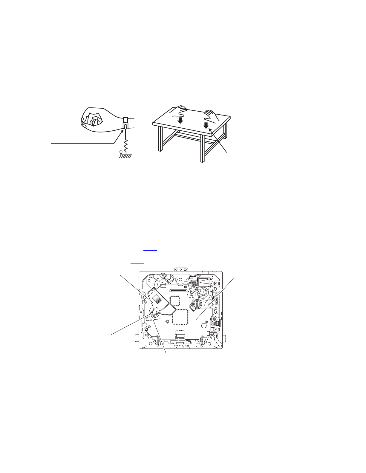
(1) Ground the workbench
Ground the workbench by laying conductive material (such as a conductive sh eet) or an iron plate over it before placing the
traverse unit (optical pickup) on it.
(2) Ground yourself
Use an anti-static wrist strap to release any static electricity built up in your body.
(caption)
Anti-static wrist strap
1M
Conductive material
(conductive sheet) or iron plate
(3) Handling the optical pickup
• In order to maintain quality during transport and before instal lation, both sides of the laser di ode on the replacement optica l
pickup are shorted. After replacement, return the shorted parts to their original condition.
(Refer to the text.)
• Do not use a tester to check the condition of the laser diode in the optical pickup. The tester's internal power source can easily
destroy the laser diode.
1.3 Handling the traverse unit (optical pickup)
(1) Before disconnecting the flexible wire from the connector CN10
ible wire.
Caution:
If you do not follow this instruction, the DVD pickup may be damaged.
(2) Disconnect the flexible wire from the connector CN10
on the front end board.
(3) Remove the solders from the short-circuit point on the flexible wire after replacing the DVD pickup.
(4) Connect the flexible wire to the connector CN10
Flexible wire
on the front end board.
on the front end board, solder the short-circuit point on the flex-
Front end board
1-4 (No.49879)
Short-circuit point
CN10
Page 5

SECTION 2
SPECIFIC SERVICE INSTRUCTIONS
This service manual does not describe SPECIFIC SERVICE INSTRUCTIONS.
(No.49879)1-5
Page 6
SECTION 3
DISASSEMBLY
3.1 Main body section
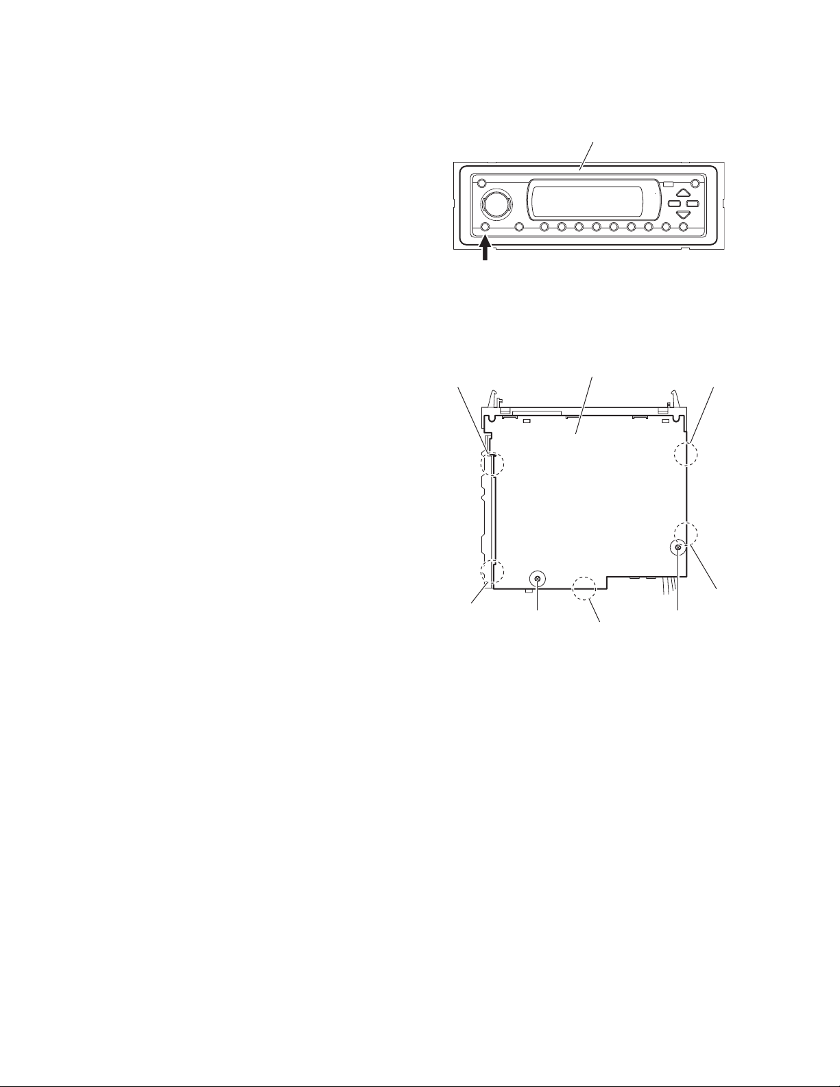
3.1.1 Removing the front panel assembly
(See Fig.1)
(1) Push the detach button i n the lower left part of the front
panel assembly and remove the front panel assembly.
3.1.2 Removing the bottom cover
(See Fig.2)
• Prior to performing the following procedures, remove the fro nt
panel assembly as required.
(1) Turn over the main body and remove the two screws A at-
taching the bottom cover.
(2) Release the two joints a, two joints b and joint c.
Caution:
Do not damage the main board when releasing the joints using
a screwdriver or a similar tool.
Detach button
Joint b
Front panel assembly
Fig.1
Bottom cover
Joint a
Joint b
A A
Joint c
Fig.2
Joint a
1-6 (No.49879)
Page 7
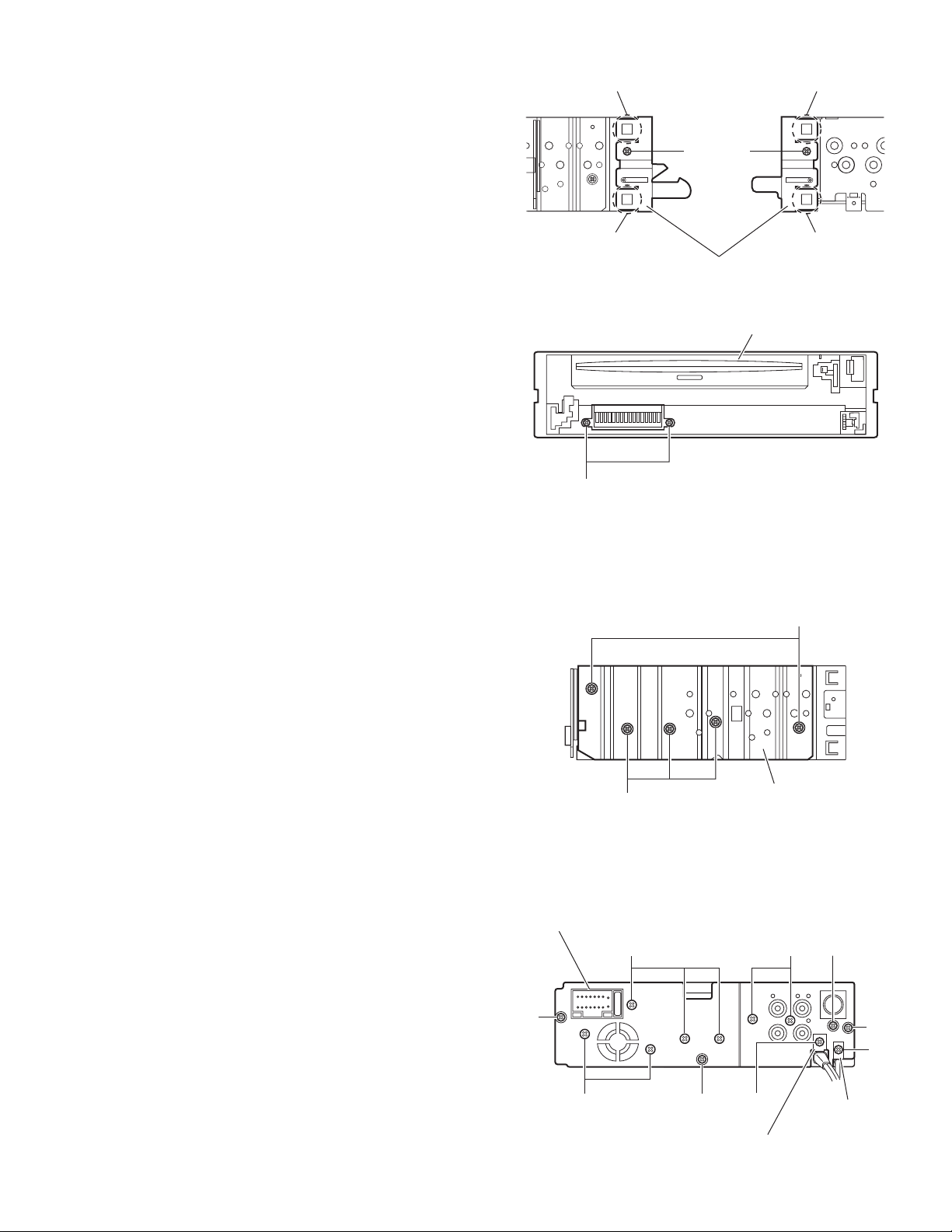
3.1.3 Removing the front chassis assembly
(See Figs.3 and 4)
• Prior to performing the following procedures, remove the front
panel assembly and bottom cover.
(1) From the both sides of the main body, remove the two
screws B attaching the front chassis assembly. (See
Fig.3.)
(2) From the front side of the main body, remove the two
screws C attaching the front chassis assembly. (See
Fig.4.)
(3) From the both sides of the main body, release the two joints
d and two joints e. (See Fig.3.)
Joint d
Joint d
C
B
Front chassis assembly
B
Fig.3
Front chassis assembly
Fig.4
Joint e
Joint e
3.1.4 Removing the heat sink
(See Fig.5)
• Prior to performing the following procedure, remove the front
panel and front chassis assemblies as required.
(1) From the left side of the main body, remove the two screws
D and three screws E attaching the heat sink.
3.1.5 Removing the rear bracket
(See Fig.6)
• Prior to performing the following procedures, remove the bot-
tom cover.
(1) From the back side of the main bo dy, remove the three
screws F, five screws G, two screws H, screw J, screw K
and screw L attaching the rear bracket.
(2) Remove the rear bracket.
Note:
When attaching the screws K and L, attach the AV cable and
antenna cable holders with them.
Rear bracket
F
D
Heat sink
E
Fig.5
JHG
F
K
G
F
AV cable holder
Fig.6
L
Antenna
cable
holder
(No.49879)1-7
Page 8
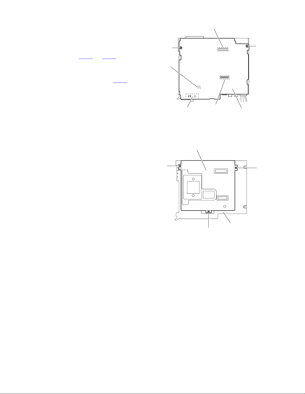
3.1.6 Removing the main board
(See Fig.7)
• Prior to performing the following procedures, remove the fro nt
panel assembly, bottom cover, front chassis assembly, heat
sink and rear bracket.
(1) Remove the two screws M attaching the main board.
(2) Disconnect the connectors CN781
board from the DVD mechanism assembly.
Reference:
Remove the fan unit as required.
(Disconnect the fan unit wire from the connector CN531
main board and remove the fan unit.)
and CN782 on the main
on the
M
CN531
CN782
M
3.1.7 Removing the DVD mechanism assembly
(See Fig.8)
• Prior to performing the following procedure, remove the front
panel assembly, bottom cover, front chassis assembly, heat
sink, rear bracket and main board.
(1) From the inside of the top chassis, remove the three
screws N attaching the DVD mechanism assembly.
Fan unit
DVD mechanism assembly
N
CN781
Fig.7
N
Fig.8
Main board
N
Top chassis
1-8 (No.49879)
Page 9

3.1.8 Removing the back end board
(See Figs.9 to 11)
• Prior to performing the following procedures, remove the front
panel assembly, bottom cover, front chassis assembly, heat
sink, rear bracket, main board and DVD mechanism assembly.
(1) From the top side of the DVD mechan ism assembly, re-
move the two screws P attaching the heat sink (MECHA).
(See Fig.9.)
(2) Remove the two screws Q attaching the shield. (See
Fig.9.)
(3) Remove the shield and heat sink (MECHA) from the DVD
mechanism assembly.
(4) Remove the two screws R attaching the heat sink (P). (See
Fig.10.)
(5) Release the two joints f and then release the two joints g.
(See Fig.10.)
(6) Disconnect the card wire from the connector CN506
back end board. (See Fig.10.)
(7) Remove the four screws S and screw S’ attaching the back
end board. (See Fig.10.)
(8) Release the three joints h and then take out the back end
board from the DVD mechanism assembly. (See Fig.11.)
Reference:
When attaching the screw S’, attach the earth wire with it. (See
Fig.11.)
on the
DVD mechanism assembly
P
Heat sink(MECHA)
Fig.9
Heat sink(P)
Joint f
Shield
Q
Back end board
R
Joint f
Joints g
Fig.10
DVD mechanism assembly
Joint h
S
CN506
Card wire
Back end board
Joint h
S
Joint h
Earth wire
S'
Fig.11
Fig.11
(No.49879)1-9
Page 10

3.1.9 Removing the front board
(See Figs. 12 to 14)
• Prior to performing the following procedures, remove the fro nt
panel assembly.
(1) From the back side of the front panel assembly, remove the
six screws T attaching the rear cover. (See Fig.12.)
(2) Release the ten joints i attaching the rear cover to the front
panel assembly. (See Fig.13.)
(3) Take out the front board from the front panel assembly.
(See Fig.14.)
Note:
Do not lose the springs when removing the front board.
Rear cover
T
T
Front panel assembly
T
T
Fig.12
Joints i
Joint i
Rear cover
Front board
Spring Spring
Joints i
Fig.13
Front panel assembly
Fig.14
Joint i
1-10 (No.49879)
Page 11

3.2 DVD mechanism assembly
3.2.1 Removing the front end board
(See Fig.1)
Caution:
Before disconnecting the flexible wire extending from the DVD
pickup, solder the short-circuit point on the flexible wire using
a grounding soldering iron. If you do not follow this instruction,
the DVD pickup may be damaged.
(1) Turn over the body, and solder the short-circuit point on the
flexible wire extending from the DVD pickup.
(2) Disconnect the flexible wire from connector CN10
front end board.
(3) Disconnect the flexible wire from connector CN201
front end board.
(4) Disconnect the flexible wire from connector CN202
front end board.
(5) Unsolder two soldering a on the front end board and dis-
connect the wire extending from the feed motor.
(6) Remove the three screws A attaching the front en d board.
Caution:
As the flexible wire to be connected to CN10
tach it to the front end board using a double tape.
Caution:
After reassembling, unsolder the short-circuit point.
, make sure to at-
on the
on the
on the
Flexible wire
Double tape
CN10
A
Short-circuit point
Front end board
A
CN201
Fig.1
Feed motor
Solder point
a.
A
CN202
(No.49879)1-11
Page 12

3.2.2 Removing the top cover
(See Fig.2)
(1) Remove the two screws B attaching the top cover on the
back of the body. Remove the top cover upward.
Reference:
When reassembling, set part b of the top cover under the
bending part c of the chassis frame.
3.2.3 Removing the mechanism section
(See Fig.2 ~ 4)
• Prior to performing the following procedure, remove the top
cover.
(1) Remove the two screws C attaching the right and left stop-
pers on the front side.
(2) Remove the two floating springs on the bottom of the body.
(3) Move the mechanism section upward and remove from the
chassis frame.
The three damper springs come off from the dampers.
Caution:
When reassembling, reattach the damper spring to the damper respectively and insert the three shafts on the bottom of the
mechanism to the dampers.
Caution:
Before inserting the shaft to the dampers, apply IPA to the hole
of damper.
Floating spring
Fig.3
Mechanism section
C
Stopper
Top cover
Stopper
C
Fig.2
B
㨎
Damper SP.(F)
(Silver)
Damper
(Black)
Damper SP.(F)
(Silver)
Damper
(Black)
Fig.4
Damper SP.(R)
(Red)
Damper
(Purple)
Chassis frame
c
1-12 (No.49879)
Page 13

3.2.4 Removing the clamper unit
(See Fig.5 ~ 9)
• Prior to performing the following procedure, re move the top
cover and the mechanism section.
(1) Remove the clamper spring on the bottom of the mecha-
nism section.
(2) Release part d of the clamper spring from the bending part
of the chassis base assembly.
(3) Move the clamper unit in the direction of the arrow and turn.
Release the two joints e and f, then remove the clamper
unit upward.
3.2.5 Reattaching the clamper unit
(See Fig.5 ~ 9)
(1) Attach the clamper spring to the clamper unit.
(2) Move the clamper unit to set the side joints e and f to each
boss of the chassis base. Make sure that part g is inserted
to the notch of the chassis base.
(3) Move the clamper spring d to the outside of th e bending
part of the chassis base.
Caution:
When reattaching, temporarily hook the end of the clamper
spring as shown in the figure to make the work easy.
Clamper unit
Clamper spring
Chassis base
d
Fig.7
Clamper unit
Clamper spring
f
Clamper2 spring
Clamper2 spring
g
Clamper spring
Fig.8
Clamper unit
e
Fig.5
Chassis base
Fig.6
Fig.9
g
Notch
(No.49879)1-13
Page 14

3.2.6 Removing the front unit
(See Fig.10 ~ 12)
• Prior to performing the following procedure, remove the top
cover and the mechanism section.
(1) Disconnect the flexible wire from connector CN202 on the
front end board at the bottom of the body.
(2) Remove the screw D attaching the front unit on top of the
body.
(3) Move the front unit toward the front to release joint h, and
release two joints i and j on the right side of the chassis
base. Then remove the front unit upward.
(4) Remove the two screws E attaching the switch board.
Reference:
You can remove the switch board only without removing the
front unit.
Caution:
When reassembling, attach the flexible wire extending from
the switch board using a double tape.
Double tape
j
i
E
Switch board
Front unit
D
Front unit
D
h
Fig.11
Front-end board
h
Fig.10
1-14 (No.49879)
CN202
Flexible wire
Fig.12
Page 15

3.2.7 Removing the loading arm S.A.
(See Fig.13, 14)
• Prior to performing the following procedure, re move the top
cover, the mechanism section and the front unit.
(1) From top of the body, move the loadi ng arm S.A. from the
front side upward, and release the bosses from the right
and left joints k and l of the chassis base.
(2) Release the boss from notch m of the connect arm on the
right side of the body, and release the boss from notch n of
the slide cam ass'y on the left side.
l
Loading arm SA
Side cam
ass'y
n
k
Fig.13
Loading arm SA
m
l
k
m
Connect arm
Fig.14
(No.49879)1-15
Page 16

3.2.8 Removing the rod (L)(R)/roller assembly
(See Fig.15 ~ 17)
• Prior to performing the following procedure, remove the top
cover, the mechanism section, the front unit and the loading
arm S.A.
(1) Release the rod (L) and (R) from the joints at the bottom of
the loading arm S.A.
(2) Remove the roller assembly from the loading A.ass'y.
(3) Remove the two collars and washer from the roller assem-
bly.
Caution:
After attaching the loading A.ass'y to the roller assembly, attach the rod (L) and (R). Attach the rods to the right and left collars of the roller as shown in Fig.16-1 and Fig.16-2.
When reattaching the rod (L) and (R) to the loading A.a ss'y,
engage each joint as shown in Fig.15. As joint n of the rod (L),
let the rod through n before reattaching it.
Joint n
Fig.16-1 Fig.16-2
Collar
Rod(R) Rod(L)
Collar
Joint n
Joint n
Rod(L)
Rod(R)
Collar
Joint n
Joint n
Rod(L)
Loading A. ass'y
Joint n
Fig.15
Collar
Washer
Roller ass'y
Rod(R)
Loading A. ass'y
1-16 (No.49879)
Fig.17
Page 17

3.2.9 Removing the DVD pickup assembly
r
(See Fig.18 ~ 20)
• Prior to performing the following procedure, remove the front
end board.
(1) At the bottom of the body. turn the feed gear in the direction
of the arrow to move the DVD pickup outwards.
(2) Remove the screw F attaching the thrust spring.
(3) Remove the DVD pickup assembly upward on the L.S.gear
side and release from sub shaft at joint o. Move the lead
screw of the DVD pickup assembly in the direction of the
arrow to release from joint p.
Caution:
When releasing the lead screw at joint p, the L.S.collar
comes off at the end of the lead screw. When reassembling, reattach the L.S.collar to the lead screw and engage joint p.
Caution:
When reattaching the L.S.collar, reattach it to the point p
of the lead screw, and to the lod (M). Make sure that the
L.S.collar is set on the lod (M) spring.
(4) Remove the screw G attaching the rack spring/ rack plate
on the DVD pickup.
(5) Pull out the lead screw.
Caution:
Perform adjustment after replacing the pickup.
DVD Pickup ass'y
DVD Pickup ass'y
Feed gear
Thrust spring
Fig.18
P
L.S.Collar
Lod(M)
F
Lead screw
Sub shaft
O
L.S.Gear
Fig.19
G
Rack spring
Lead screw
Rack plate
L.S.Gea
L.S.Collar
DVD Pickup
Fig.20
(No.49879)1-17
Page 18

3.2.10 Removing the spindle motor
r
(See Fig.21)
• Prior to performing the following procedure, remove the front
end board.
(1) Remove the two screws H attaching the spindle motor on
the bottom of the body.
Caution:
Perform adjustment when reattaching the spindle motor.
3.2.11 Removing the FL motor S.A.
(See Fig.22, 23)
• Prior to performing the following procedure, remove the front
end board.
(1) Remove the feed TRI.spring on the bottom of the body.
(2) Remove the two screws I attaching the FL motor SA.
(3) Remove the slit washer from the motor H.ass'y and pull out
the worm wheel.
(4) Remove the two screws J attaching the FL motor.
Spindl motor
H
Fig.21
Slit washer
Worm wheel
F.T.Spring
Fig.22
I
FL Motor SA
FL Moto
J
Motor H.ass'y
Fig.23
1-18 (No.49879)
Page 19

SECTION 4
ADJUSTMENT
4.1 Test instruments require d for ad justment
(1) Digital oscilloscope (100MHz)
(2) Jitter meter
(3) Digital tester
(4) Electric voltmeter
(5) Tracking offset meter
(6) Test Disc : VT501 or VT502
(7) Extension cable for check
(8) Extension studs and FFC extension cable
4.3 For comfirmation of the Main board and mechanism movements Connecting diagram 1 of extension cable
4.2 Standard measuring conditions
Power supply voltage : DC14.4V(11V to 16V)
Load impedance : 4 Ω (2 Speakers connection)
Line output : 20k Ω
Caution:
Be sure to attach the heat sink and rear bracket onto the
power amplifier IC and regulator IC respectively, before
supply the power.
If voltage is applied without attaching these parts, the
power amplifier IC and regulator IC will be destroyed by
heat.
Extension cable
EXTGS004-26PL
Heat sink
Main board
Extension cable
EXTDV001-20P
Rear bracket
Extension stud
STDV001-3P
Extension studs
STDV001-3P
(No.49879)1-19
Page 20

4.4 For the adjustment of the jitter after replacing the pickup
Connecting diagram 2 of extension cable
Procedure
Remove the screws attaching the backend board from the mechanism side, connect the backend board to the connectors (26pins/
20pins) on the main board.
After attaching the top chassis and front panel assemblies to th e main board, attach the exten sion studs (STDV001-3P) on the
top chassis and then attach the mechanism assembly with the nuts.
Nut
Extension stud
STDV001-3P
Backend board
Extension stud
STDV001-3P
FFC extension cable
EXTDV001-50PF
Disconnect the FFC cable
1-20 (No.49879)
Main board
Page 21

After replacing the pickup, set the unit in the service mode to display a jitter value on the LCD.
Confirm that the jitter value measured with a jitter meter is within 1.2% of the jitter value displayed on the LCD. If it is within 1.2%,
then adjustment is not necessary. Please note that a jitte r value displayed on the L CD is hex data. Refer to the corresponding
decimal notation value using the Jitter Conversion Table and confi r m it with the measured value.
Fix the screws "a", "b" and "c" with screw lock paint.
If the measured jitter value is outside the 1.2% tolerance range, perform the following adjustments.
c
b
a
Jitter value adjustment procedure (Pickup horizontal level adjustment relati ve to the DVD recording surface)
(For the adjustment tool use a 3 mm wrench and not a screwdriver, this procedure will make the adjustment easier.)
3 mm wrench
(1) Set the unit to the service mode and display a jitter value (hex data) on the LCD.
(2) Turn each of the screws a, b and c, by a half-turn per step, in the direction that reduces the jitter value in order to minimize it.
(Do not turn a screw more than a half turn at a time, but adjust the screws in the cycle of a → b → c → d → a.)
(3) After completing the adjustment, secure the screws with screw lock paint.
(No.49879)1-21
Page 22

4.5 Jitter value conversion table
Load the test DVD and set the unit to the service mode. A jitter value converted to the hex value is displayed on the LCD. Refer to the
corresponding decimal notation value shown in the following Jitter Conversion Table.
The adjustment is OK if the jitter value measured with a jitter meter is within 1.2% of the jitter value displayed on the LCD.
If the measured jitter value is outside the 1.2% tolerance range, adjust it to minimize the difference between the measured value and
the displayed value.
Indicated on
the LCD
20A7 4.7 1AA0 7.6 149A 10.5 E93 13.4
2072 4.8 1A6B 7.7 1464 10.6 E5E 13.5
203D 4.9 1A36 7.8 142F 10.7 E28 13.6
2008 5.0 1A01 7.9 13FA 10.8 DF3 13.7
1FD2 5.1 19CC 8.0 13C5 10.9 DBE 13.8
1F9D 5.2 1996 8.1 1390 11.0 D89 13.9
1F68 5.3 1961 8.2 135A 11.1 D54 14.0
1F33 5.4 192C 8.3 1325 11.2 D1E 14.1
1EFE 5.5 18F7 8.4 12F0 11.3 CE9 14.2
1EC8 5.6 18C2 8.5 12BB 11.4 CB4 14.3
1E93 5.7 188C 8.6 1286 11.5 C7F 14.4
1E5E 5.8 1857 8.7 1250 11.6 C4A 14.5
1E29 5.9 1822 8.8 121B 11.7 C14 14.6
1DF4 6.0 17ED 8.9 11E6 11.8 BDF 14.7
1DBE 6.1 17B8 9.0 11B1 11.9 BAA 14.8
1D89 6.2 1782 9.1 117C 12.0 B75 14.9
1D54 6.3 174D 9.2 1146 12.1 B40 15.0
1D1F 6.4 1718 9.3 1111 12.2 B0A 15.1
1CEA 6.5 16E3 9.4 10DC 12.3 AD5 15.2
1CB4 6.6 16AE 9.5 10A7 12.4 AA0 15.3
1C7F 6.7 1678 9.6 1072 12.5 A6B 15.4
1C4A 6.8 1643 9.7 103C 12.6 A36 15.5
1C15 6.9 160E 9.8 1007 12.7 A00 15.6
1BE0 7.0 15D9 9.9 FD2 12.8 9CB 15.7
1BAA 7.1 15A4 10.0 F9D 12.9 996 15.8
1B75 7.2 156E 10.1 F68 13.0 961 15.9
1B40 7.3 1539 10.2 F32 13.1 92C 16.0
1B0B 7.4 1504 10.3 EFD 13.2
1AD6 7.5 14CF 10.4 EC8 13.3
Jitter value
Indicated on
the LCD
Jitter value
Indicated on
the LCD
Jitter value
Indicated on
the LCD
Jitter value
1-22 (No.49879)
Page 23

SECTION 5
TROUBLE SHOOTING
5.1 Service mode Standard input/output conditions
Power supply voltage : DC14.4V (11V to 16V)
Load impedance : 4 Ω (2 Speakers connection)
Line output : 20k Ω
Service mode setting procedure
(The DVD does not need to be loaded before starting the following procedure.)
SRC
ATT
SEL
(b) A TT(c) SRC
(a) SEL (e) 6 (d)
4
3
5
MODE
DISP
M
6
TI21
D
With the unit turned on, perform the following steps.
1. While holding the button (a), press buttons (b) and (c) together so that the LCD displays the following:
AREA/REGION
VERSION
RUNNING MODE
CHECK MODE
EXPERT MODE
2. Press button (b) three times in order to select "CHECK MODE," and then press button (a) so that the LCD
displays the following.
CHECK MODE
PRESS A/D KEY
Load the test DVD (VT501 or VT502) (this operation is not necessary if the disc has been loaded before
starting this procedure), and then press button (e) so that the LCD displays the following.
CHECK MODE
PRESS A/D KEY
DUDx1 JITTER MODE
CURRENT:
JITTER:
When the LCD displays the above, the unit is in the jitter adjustment mode.
is a hex number. (Refer to section 4.5, "Jitter Conversion Table.")
(No.49879)1-23
Page 24

Operation procedures
s.
Press the [SEL], [POWER]
and [SOURCE] keys
simultaneously for 2 seconds.
The unit enters the service mode.
"AREA/REGION" is
indicated on the LCD.
Press the [SEL] key
Press the [DISC UP] or [DISC DW] key
"VERSION" is
indicated on the LCD.
Press the [SEL] key
Press the [DISC UP] or [DISC DW] key
"RUNNING MODE" is
indicated on the LCD.
Press the [SEL] key
Press the [DISC UP] or [DISC DW] key
"CHECK MODE" is
indicated on the LCD.
Press the [SEL] key
Press the [DISC UP] or [DISC DW] key
Destination area/region display
************
************
************
System control destination
DVD unit destination
DVD unit region
Microcomputer version display
************
************
************
************
System control microcomputer version
Front end microcomputer version
Back end microcomputer version
DVD back end SDK version
Running mode: For use in running tests.
DVD unit check mode
(See section "DVD check mode" for details.)
"EXPERT MODE" is
indicated on the LCD.
Press the [DISC UP] or [DISC DW] key
"TEMPERATURE" is
indicated on the LCD.
Press the [DISC UP] or [DISC DW] key
A B
Press the [SEL] key
Press the [SEL] key
DVD unit expert mode
Thermistor's temperature data readout
: Data in the temperature sensor in the system control
is read every 5 seconds and displayed in hex number
1-24 (No.49879)
Page 25

A B
"READ ERROR" is
indicated on the LCD.
Read loading and ejection error history
Press the [SEL] key
: The error history saved in the system control
is read and displayed.
TOTAL ERROR zzzz : Total error count.
Total error count
(A figure between 0 and 9999 is
displayed. 10000 or more is also
displayed as 9999.)
E-n xxyyyy : Latest three error codes.
Detailed error code
Error code
Counter
EOn xxyyyy : First five error codes
Detailed error code
Error code
Frror code (1 byte)
First byte [01] Eject error
[09] Loading error
Counter
Detailed error codes (2 bytes) Displayed with loading/ejection errors only.
First byte
Second byte
(Example) When a switch status error occurs during loading route 3 and
the switch status is L/L/H/H/H (00111B = 07H), the error code
and detailed error code become: [09 3207].
Route No. (EJECT route No.)
Higher 4 bits
Lower 4 bits
[1] Time out
[2] Switch status error
[3] Swinging error
bit7
bit6,5
bit4
bit3
bit2
bit1
bit0
-
1(2)
1(2)
Disc type (0: 12 cm. 1: 8 cm)
Fixed at 0
SW1 status
SW2 status
SW3 status
SW4 status
REST SW status
SW1/2/3/4
1,1,1,1
0,1,1,1
0,0,1,1
Route No. (Process of error occurrence)
Refer to charts 1.1 and 1.2.
Error type
[Rest SW]
[0]
[0]
[0]
Loading
No Disc
Disc insert
detection
Eject
No Disc
Eject
completion
Reload
Disc push in
C D
2(2)
2(2)
2(2)
2(2)
3(1)
3(1)
0,0,0,1
0,0,1,1
0,1,1,1
1,1,1,1
1,1,1,0
1,1,1,0
[0]
[0]
[0]
[0]
[0]
[1]
Load completion
Chart 1.1 12cm Disc switch status transition
Route No. (EJECT route No.)
-
1(2)
1(2)
2(2)
2(2)
3(1)
3(1)
Transition in the center loading (Similar to 12cm in the side loading)
SW1/2/3/4
1,1,1,1
0,1,1,1
0,0,1,1
0,1,1,1
1,1,1,1
1,1,1,0
1,1,1,0
[Rest SW]
[0]
[0]
[0]
[0]
[0]
[0]
[1]
Loading
No Disc
Disc insert
detection
Load completion
Chart 1.2 8cm Disc switch status transition
Eject start
Eject
No Disc
Eject
completion
Eject start
Reload start
Load completion
Reload
Disc push in
Reload start
Load completion
(No.49879)1-25
Page 26

C D
Press the [DISC UP] or [DISC DW] key
"CLEAR ERROR" is
indicated on the LCD.
Press the [SEL] key
Press the [DISC UP] or [DISC DW] key
"READ CH-ERROR" is
indicated on the LCD.
Press the [SEL] key
Press the [DISC UP] or [DISC DW] key
"CLEAR CH-ERROR" is
indicated on the LCD.
Press the [SEL] key
Press the [DISC UP] or [DISC DW] key
"INITIALIZE" is
indicated on the LCD.
Press the [SEL] key
Clear loading/ejection error history
: The error history stored in the EEPROM is cleared
(by writing 00h).
Read changer error history
: The error history saved in the CD changer is read out
(provided that the data is returned in less than 2 seconds after
connection to 93 address).
Clear changer error history
: The error history saved in the CD changer is cleared.
Initialize user set data
: The system control EEPROM is initialized except for the
loading/ejection error history.
Press the [DISC UP] or [DISC DW] key
"INITIALIZE ALL" is
indicated on the LCD.
Press the [SEL] key
Press the [DISC UP] or [DISC DW] key
"MEMORY CHECK" is
indicated on the LCD.
Press the [SEL] key
Initialize all data to the factory setting
: The system control EEPROM is initialized entirely.
Memory check
: The remaining data capacity of the disc is displayed on the LCD.
1-26 (No.49879)
Page 27

DVD unit check mode
Check item list
(1) Select "CHECK MODE" in the service mode.
(2) Various check modes can be displayed according to the key operations.
No. A/D key
1
[1]
2
[2]
3
[3]
4
[4]
5
[5]
6
[6]
7
[F-SKIP]
8
[B-SKIP]
9
[SRC]
10
[MODE]
11
[DISP]
12
[TI]
13
[DISC UP]
14
[DISC DOWN]
DVD unit operation
Disc startup and through playback
(Playback starts from the start position)
Tracking on the outermost position of CD
Tracking on the innermost position of CD
CD_LD lights and laser current is displayed
DVD_LD lights and laser current is displayed
DVD x1 jitter measuring mode
(for use in mechanism adjustment)
Contents of EEPROM used by mechanism
(0x00 - 0xFF displayed (FWD))
Contents of EEPROM used by mechanism
(0x00 - 0xFF displayed (BWD))
Initialization of EEPROM contents used by
the mechanism
Search & jitter measurement of the specified
position of DVD-SL
Search & jitter measurement of the specified
position of opposite disc of the DVD-DL
Search & jitter measurement of the specified
position of parallel disc of DVD-DL
Disc playback
Disc stopped & LD-OFF
Indicated
on the LCD
[__CHECK__]
[OUT_TROFF]
[IN_TROFF]
[ ]
[ ]
[ ]
[ ]
[ ]
[_____]
[ ]
[ ]
[ ]
[ ]
[__CHECK__]
Remark
CHECK display remains
For EF phase error
For EF phase error
: : Laser current value
: Jitter value
: Laser current value
: Jitter value
: Laser current value
: Jitter value
: EEPROM address
: EEPROM contents
: EEPROM address
: EEPROM contents
No display
: 0x00-0x02
(Position measured with VT-502)
: Jitter value
: 0x00-0x06
(Position measured with VT-501)
: Jitter value
: 0x00-0x06
(Position measured with VT-501)
: Jitter value
: Laser current value
: Jitter value
CHECK display remains
15
When disc is
opened
or [TEST8]
16
When disc is
closed
(Cautions for Operation)
• Press key [1] of No. 1 before an item in which the No. 2 or 3 key is pressed.
• Press key [6] of No. 6 before an item in which one of the No. 10, 11 or 12 keys is pressed.
• The check mode can be exited either by pressing the [POWER] key or by resetting the unit.
OPEN
CLOSE
[__CHECK__]
[__CHECK__]
CHECK display remains
CHECK display remains
(No.49879)1-27
Page 28

5.2 Firm ware upgrade [Use remote controller RM-RK210]
(1) Upgrade
• Video out terminal connect to TV monitor.
• Insert upgrade disc (written firm ware) to set.
• "firmware upgrade DISC... press UP" on TV monitor.
• Push "UP" button on remote controller.
• "upgrade complete: rebooting in* "
"UP" button on remote controller
Wait until this indication on TV monitor up side.
• Then push "EJECT" button.
• Later automatically DISC eject.
(It takes time for a long than usual eject.)
(2) Complete work
• Push 3 button at same time for a while "SEL" "SRC" "POWER" (keep thgis order).
• Push button indicate "INITIALIZE" on LCD.
• Then push "SEL" button. Indicate "COMPLETED" on LCD: OK
(3) Power OFF
• Push power button → Power is OFF.
5.3 Shipping position (Final process)
(1) Confirm firm ware
a) Push 3 button at same time for a while "SEL" "SRC" "POWER" (keep this order).
b) Indicate on LCD "AREA/REGION" → Push "SEL" button.
c) Confirm on LCD "B/E AREA" is "U" "A".
d) Next push "UP" button.
e) Confirm on LCD "B/E-VER" is "CORRECT NUMBER" (Refer to W/STD VDG3163 10 14/)
Reference
ERSION B/E-AREA B/E-VER
U U REFER FA W/STD
A A REFER FA W/STD
VERSION B/E-AREA B/E-VER
J J REFER FA W/STD
E E REFER FA W/STD
U U REFER FA W/STD
A A REFER FA W/STD
DOM DOM REFER FA W/STD
DISC+
1-28 (No.49879)
Page 29

(No.49879)1-29
Page 30

VICTOR COMPANY OF JAPAN, LIMITED
AV & MULTIMEDIA COMPANY MOBILE ENTERTAINMENT CATEGORY 10-1,1chome,Ohwatari-machi,Maebashi-city,371-8543,Japan
(No.49879)
Printed in Japan
WPC
 Loading...