

Page 1
Memory Recorder
KA-MR100G
INSTRUCTIONS
Thank you for purchasing this JVC product. Before
beginning to operate this unit, please read the
instructions carefully to ensure the best possible
performance.
For Customer Use:
Enter below the Serial No. which is located on the
body. Remain this information for future reference.
Model No. : KA-MR100G
Serial No. :
LST0838-001A
Page 2
Getting Started
FOR USA
These are general IMPORTANT SAFEGUARDS and certain items may not apply to all appliances.
IMPORTANT SAFEGUARDS
Read all of theseinstructions.
1.
Save theseinstructions for later use.
2.
All warnings on the product and in the operating instructionsshould be adhered to.
3.
Unplug thisappliance system from the wall outlet before cleaning. Do not use liquid cleaners or aerosol
4.
cleaners.Use a damp cloth for cleaning.
Do not use attachments not recommended by the appliance manufacturer as they maycausehazards.
5.
Do not use thisappliance nearwater - for example, near abathtub,washbowl, kitchen sink, or laundry tub,ina wet
6.
basement, or near aswimming pool, etc.
Do not place thisappliance on an unstable cart, stand, or table. The appliance mayfall,
7.
causing serious injury to a child or adult, and serious damage to the appliance.
Use only with a cart or stand recommended by the manufacturer, or sold with the appliance.
Wall or shelf mounting should follow the manu
mounting kit approved by the manufacturer. An appliance and cart combination should be
moved with care.
Quick stops, excessive force, and uneven surfaces maycause the appliance and cart
combination to overturn.
Slotsand openings in the cabinet and the back or bottom are provided for ventilation, and to insure reliable operation of
8.
the appliance and to protect it from overheating, these openings must not be blocked or covered. The openingsshould
never be blocked byplacing the appliance on abed, sofa,rug, or other similar surface.
Thisappliance should never beplaced near or over a radiator or heat regi
Thisappliance should not beplaced in abuilt-in installation such asabookcase unless proper ventilation is provided.
Thisappliance should be operated only from the type of power source indicated on the marking label. If youare not sure
9.
of the type of power supplied to your home, consult yourdealer or local power company. For appliance designed to
operate from battery power, refer to the operating instructions.
For added protection for this product during a lightning storm, or when it is left unattended and unused for long periods
10.
of time, unplug it form the wall outlet and disconnect the antenna or cable system. This will prevent damage to the
product due to lightning and power-line surges.
Do not allow anything to rest on the power cord. Do not locate thisappliance where the cord will be abused by persons
11.
walking on it.
Follow all warningsand instructions marked on the appliance.
12.
Do not overloadwall outletsand extension cordsasthis canresult in fire or electric shock.
13.
Never pushobjects of any kind into thisappliance through cabinet slotsasthey maytouch dangerous voltage points or
14.
short outparts thatcould result in a fire or electric shock. Never spill liquid of any kind on the appliance.
Do not attempt to service thisappliance yourself as opening or removing covers may exposeyou to dangerous voltage
15.
or other hazards. Refer all servicing to qualified service personnel.
Unplug thisappliance from the wall outlet and refer servicing to qualified service personnel under the following conditions:
16.
a. When the power cord or plugis damaged or frayed.
b. If liquid has been spilled into the appliance.
c. If the appliance has been exposed to rain or water.
d.
If the appliance does not operate normally by following the operating instructions. Adjus
are covered by the operating instructionsasimproper adjustment of other controls mayresult in damage and will
often require extensive work by a qualified techniciantorestore the appliance to normal operation.
e. If the appliance has been dropped or the cabinet has been damaged.
f.
When the appliance exhibitsadistinct change in performance - this indicatesaneed for service.
When replacement partsare required, be sure the service technicianhas used replacement partsspecified by the
17.
manufacturer thathave the same characteristicsasthe originalpart. Unauthorized substitutions mayresult in fire,
electric shock, or other hazards.
Upon completion of any service or repairs to thisappliance, ask the service technician to perform routine safety checks
18.
to determine that the appliance is in safe operating condition.
facturer's instructions, and should use a
ster.
PORTABLE CART WARNING
(symbol provided by RETAC)
S3125A
t only those controls that
I
Page 3
Safety Precautions
FOR USA AND CANADA
CAUTION
RISK OF ELECTRIC SHOCK
DO NOT OPEN
CAUTION:
INFORMATION:
This equipment has been tested and found to comply with the limits
for a Class A digital device, pursuant to Part 15 of the FCC Rules.
These limits are designed to provide reasonable protection against
harmful interference when the equipment is operated in a
commercial environment.
This equipment generates, uses, and can radiate radio frequency
energy and, if not installed and used in accordance with the
instruction manual, may cause harmful interference to radio
communications.
Operation of this equipment in a residential area is likely to cause
harmful interference in which case the user will be required to correct
the interference at his own expense.
CAUTION:
CHANGES OR MODIFICATIONS NOT APPROVED BY JVC
COULD VOID USER’S AUTHORITY TO OPERATE THE
EQUIPMENT.
NOTE:
The rating plate (serial number plate) is on this unit.
WARNING:
TO REDUCE THE RISK OF FIRE OR ELECTRIC SHOCK, DO NOT
EXPOSE THIS APPLIANCE TO RAIN OR MOISTURE.
TO REDUCE THE RISK OF ELECTRIC
SHOCK. DO NOT REMOVE COVER (OR
BACK).
NO USER-SERVICEABLE PARTSINSIDE.
REFER SERVICING TO QUALIFIED
SERVICE PERSONNEL.
The lightning flash with arrowhead symbol,
within an equilateral triangle is intended to
alert the user to the presence of uninsulated
"dangerous voltage" within the product's
enclosure that may be of sufficient magnitude
to constitute a risk of electric shock to
persons.
The exclamation point within an equilateral
triangle is intended to alert the user to the
presence of important operating and
maintenance (servicing) instructions in the
literature accompanying the appliance.
POUR CANADA
ATTENTION
RISQUE D’ELECTROCUTION NE
PAS OUVRIR
ATTENTION:
POUR EVITER TOUT RISQUE D’ELECTROCUTION
NE PAS OUVRIR LE BOITER.
AUCUNE PIECE INTERIEURE N’EST A REGLER
PAR L’UTILISATEUR.
SE REFERER A UN AGENT QUALIFIE EN CAS DE
PROBLEME.
Le symbole de l’éclair à l’intérieur d’un triangle
équilatéral est destiné à alerter l’utilisateur sur la
présence d’une “tension dangereuse” non isolée
dans le boîtier du produit. Cette tension est
suffisante pour provoquer l’électrocution de
personnes.
Le point d’exclamation à l’intérieur d’un triangle
équilatéral est destiné à alerter l’utilisateur sur la
présence d’opérations d’entretien importantes au
sujet desquelles des renseignements se trouvent
dans le manuel d’instructions.
Ces symboles ne sont utilisés qu’aux Etats-Unis.
INFORMATION (FOR CANADA)
RENSEIGNEMENT (POUR CANADA)
This Class A digital apparatus complies with Canadian
ICES-003.
Cet appareil numérique de la Class A est conforme à la
norme NMB-003 du Canada.
WARNING:
TO REDUCE THE RISK OF FIRE OR ELECTRIC
SHOCK, DO NOT EXPOSE THIS APPLIANCE TO RAIN
OR MOISTURE.
CAUTION:
This unit should be used with 12V DC only.
To prevent electric shocks and fire hazards, do NOT use any
other power source.
NOTE:
The rating plate (serial number plate) is on the unit.
REMARQUE:
La plaque signalétique (plaque du numéro desérie) est située sur
le cadre inférieur de l’unité.
CAUTION:
To prevent electric shock, do not open the cabinet. No user
serviceable parts inside. Refer servicing to qualified service
personnel.
Due to design modifications, data given in this instruction book
are subject to possible change without prior notice.
THIS DEVICE COMPLIES WITH PART 15 OF THE FCC
RULES.
OPERATION IS SUBJECT TO THE FOLLOWING TWO
CONDITIONS: (1) THIS DEVICE MAY NOT CAUSE
HARMFUL INTERFERENCE, AND (2) THIS DEVICE MUST
ACCEPT ANY INTERFERENCE RECEIVED, INCLUDING
INTERFERENCE THAT MAY CAUSE UNDESIRED
OPERATION.
The apparatus shall not be exposed to dripping or splashing and
that no objects filled with liquids, such as vases, shall be placed
close to the apparatus.
AVERTISSEMENT:
POUR EVITER LES RISQUES
D'INCENDIE OU D'ELECTROCUTION, NE PAS
EXPOSER L'APPAREIL A L'HUMIDITE OU A LA
PLUIE.
ATTENTION:
Ce magnétoscope ne doit être utilisé que sur du courant
direct en 12V.
Afin d’eviter tout resque d’incendie ou d’electrocution, ne
pas utillser d’autressources d’alimentation électrique
.
II
Page 4
Getting Started
Safety Precautions
(continued)
FOR EUROPE
This equipment is in conformity with the provisions and protection
requirements of the corresponding European Directives. This
equipment is designed for professional video appliances and can be
used in the following environments:
● Controlled EMC environment (for example, purpose-built broad-
casting or recording studio), and rural outdoors environments.
In order to keep the best performance and furthermore for
electromagnetic compatibility we recommend to use cables not
exceeding the following lengths:
Cable Maximum Cable
Length
IEEE1394 CABLE Shield Cable 0.2 m
Caution:
Where there are strong electromagnetic waves or magnetism, for
example near a radio or TV transmitter, transformer, motor, etc.,
the picture and the sound may be disturbed. In such case, please
keep the apparatus away from the sources of the disturbance.
Dear Customer,
This apparatus is in conformance with the valid European directives and
standards regarding electromagnetic compatibility and electrical safety.
European representative of Victor Company of Japan, Limited is:
JVC Technical Services Europe GmbH
Postfach 10 05 04
61145 Friedberg
Germany
Sehr geehrter Kunde, sehr geehrte Kundin,
dieses Gerät stimmt mit den gültigen europäischen Richtlinien und
Normen bezüglich elektromagnetischer Verträglichkeit und
elektrischer Sicherheit überein.
Die europäische Vertretung für die Victor Company of Japan,
Limited ist:
JVC Technical Services Europe GmbH
Postfach 10 05 04
61145 Friedberg
Deutschland
Information for Users on Disposal of Old Equipment
[European Union]
Attention:
Thissymbol i
Union.
Thissymbol indicates that the electrical and electronic
equipment should not bedisposed as generalhousehold
waste atits end-of-life. Instead, the product should behanded
over to the applicable collection point for the recycling of
electrical and electronic equipment for proper treatment,
recovery and recycling in accordance with yournational
legislation.
By disposing of this product correctly, you will help to conserve
naturalresourcesand will help prevent potential negative
effects on the environment and humanhealth which could
otherwise becaused byinappropriate waste handling of this
product. For more information about collection point and
recycling of this product, please contact your localmunicipal
office, yourhousehold waste disposal s
where you purchased the product.
for incorrect disposalofthis waste, in accordance with national
legislation.
sonly valid in the European
ervice or the shop
Penalties may be applicable
(Business users)
If you wishtodisposeofthis product, pleasevisit ourweb
page http://www.jvc.eu to obtain information about the takeback of the product.
[Other Countries outside the European Union]
If you wishtodisposeofthis product, pleasedosoin
accordance with applicable national legislation or other rules
in yourcountry for the treatment of old electrical and
electronic equipment.
III
Page 5
Features
This is a memory recorder to record and play back HD-format video
images and audio signals on an SxS memory card via the IEEE1394
interface.
Use of SxS Memory Card
The use of MPEG-2 Long GOP compression format and SxS
memory card enables long-duration recording and high-speed
transfer as described below.
● Supports long-duration recording of HD images up to 180
minutes (when capacity is 32 GB and mode is set to 720p).
● Enables high-speed data transfer to a computer, thus enhancing
workflow efficiency.
Attachment to Professional HD Camcorders
● This memory recorder can be attached to the GY-HD200/HD250
HD camcorder series to enhance shooting that requires a high
level of mobility.
● Besides recording to SxS memory cards, hybrid recording and
series recording through combined use with cassette tapes are
also supported.
Use of MP4 File Format T1
● MP4 file format, compliant file format used on the “XDCAM EX”.
T Play back compatibility may be not guaranteed on the different
type products, due to variation of supported recording mode.
T1:MP4 File Format
This format adopts the Professional Memory Card System
Format licensed from Sony Corporation.
Contents
Getting Started
Safety Precautions ....................................................................... II
Features ....................................................................................... 2
Contents ...................................................................................... 2
Precautions .................................................................................. 3
Name and Function of Parts ........................................................ 4
LCD Panel Displays ..................................................................... 5
Setup
Attaching the Memory Recorder to a Camcorder ........................6
Connecting IEEE1394 .................................................................7
Turning On/Off the Power ............................................................7
Setting the Date/Time .................................................................. 7
Inserting/Removing the SxS Memory Card .................................8
Maximum Recording Time of SxS Memory Card ........................8
Operation
Recording Video Images of the Camcorder Using the Memory
Recorder ...................................................................................... 9
Playing Video Images Recorded in the Memory Recorder ........ 10
Menu
Setting the Menu Screen ........................................................... 11
Menu Screen Configurations and Functions .............................. 12
Others
Warning Messages .................................................................... 14
Error Messages .........................................................................14
Troubleshooting .........................................................................15
Specifications ............................................................................ 16
UTC Time Difference Chart by Region ...................................... 17
The following are included in the bundled CD-ROM.
<Softwares>
● SxS memory card device driver software for computers
● Computer application software (JVC ProHD Clip Manager)
● Plugin software for Final Cut Pro (JVC ProHD Log and Transfer
Plugin) T1
T1: AFinal Cut ProB is a video editing software developed by
Apple Inc.
<Documents>
● KA-MR100G instruction manual
(Japanese, English, German, French, Italian, Spanish,
Russian, and Chinese versions)
● SxS memory card device driver software installation guide
● JVC ProHD Clip Manager user’s guide/JVC ProHD Log and
Transfer Plugin user’s guide.
For procedures on how to install the application software on a
computer, please refer to the user’s guide or instruction
manual.
Copyrights
● Broadcasting for profit or public viewing of the video and
audio contents recorded using this product may infringe
on authors’ rights protected by copyright law.
● Recorded video and audio contents cannot be used
without the consent of the right-holder under copyright
law, except for personal enjoyment.
How to Read this Manual
䡵 Symbols used in this manual
Note : States precautions to be taken during operation.
Memo : States restrictions on the functions or use of this
equipment. For reference purposes.
A : Indicates the page numbers or items to refer to.
䡵 Contents of this manual
● JVC holds the copyright to this manual. Any part or all of this
manual may not be reproduced without prior consent from the
company.
● Product names of other companies described in this manual
are trademarks or registered trademarks of the respective
companies. Symbols such as 姠, 姞 and 姝 are omitted in this
manual.
● Design, specifications and other contents described in this
manual are subject to change for improvements without prior
notice.
● XDCAM EX is Sony Corporation’s brand name for its
professional video camera series.
● Windows is a registered trademark of Microsoft Corporation in
the U.S.
● Mac OS and Final Cut Pro are trademarks of Apple Inc.,
registered in the United States and other countries.
2
Page 6

Getting Started
Precautions
Storage and Operating Environment
䡵
Do not store this product in the following environments.
Doing so may result in malfunction or failure.
● Hot or cold locations beyond the allowable operating
temperature range of 0 I to 40 I.
● Locations beyond the allowable operating humidity range
of 30 % RH to 80 % RH (no condensation)
● Near equipment that emits strong magnetic fields, such as
transformers or motors
● Near equipment that emits radio waves, such as
transceivers and mobile phones
● Locations with excessive dust and sand
● Locations that are subjected to strong vibrations
● Locations prone to moisture, such as window side
● Locations that are subjected to steam or oil, such as
kitchens
● Locations that are subjected to radiation, X-rays, or
corrosive gases
Precautions for Handling the
Memory Recorder
● When connecting and recording with a camcorder other
than GY-HD200/GY-HD250, the recording may not work
properly.
● Playing back clips that are created on devices other than
the KA-MR100G Memory Recorder may result in distorted
images and choppy sound.
● Please do not use the battery that cannot be connected
with this product.
● Make sure that the power switch is turned off before
removing the battery. Failure to do so may result in
malfunction of the memory recorder or SxS memory card.
● Do not unplug the IEEE1394 cable during recording or
playback.
● When power is not supplied for a prolonged period of time
(three months or longer), the initial setting screen appears
when the power is next turned on.
● Do not place objects on the memory recorder.
● This product cannot be used by connecting the IEEE1394
terminal of the KA-UM100G adapter (sold separately) to
the computer.
● Please contact our authorized dealers if inspection of the
interior components or repair is required.
Fire Hazard, Electrical Shock and
Injury
● Do not place this product on unstable surfaces as it may
fall and lead to injuries or malfunction of the product. When
this product is attached to a camcorder, carry it by holding
the handle of the camcorder.
● Do not remove or modify the cover of this product. It might
result in fire, electrical shock or malfunction of the product.
● Do not insert objects other than the memory card into the
card slot. Inserting a metallic or flammable object may
result in fire, electrical shock or malfunction of the product.
Accessories
䡵 To use the ExpressCard slot on the computer,
installation of the SxS memory card device driver
software is required. The driver can be found in
the bundled CD-ROM.
䡵 To copy a video clip to the computer,
installation of the computer application software
(JVC ProHD Clip Manager) is required. This
program can be found in the bundled CD-ROM.
䡵 To load recorded video clips to Apple Inc.’s
video editing software, Final Cut Pro, installation
of the Final Cut Pro plugin software (JVC ProHD
Log and Transfer Plugin) is required. This
software can be found in the bundled CD-ROM.
䡵 For procedures on how to install the software,
please refer to the user’s guide and instruction
manual in the bundled CD-ROM.
Precautions for Handling SxS
Memory Cards
䡵 Make sure that the SxS memory card is
formatted on this memory recorder. SxS memory
cards that are formatted on another product
cannot be used on this memory recorder.
䡵 Formatting an SxS memory card erases all clips
that are stored on the card.
䡵 Make sure to close the card slot cover before
using the memory card.
䡵 Do not operate the write-protect switch of the
SxS memory card when it is inserted into the
memory recorder.
䡵 For details, please refer to the instruction
manual of the SxS memory card.
Precautions for Handling Recorded
Video Clips
䡵 We do not guarantee against damage of the
recorded video clips if the SxS memory card is
removed from the slot while data is being
accessed (e.g., during recording, playback or
formatting). Remove the card only when the
access lamp of the memory recorder lights up in
green.
䡵 We do not guarantee against damage of the
recorded video clips in the following cases:
● when this product is used in places subject to static
electricity or electrical noises;
● when the battery or IEEE1394 cable is removed while data
is being accessed;
● when this product is used in sandy or dusty places, or
when a dirty SxS memory card is used.
䡵 The recovery feature does not guarantee
successful recovery of the damaged files.
JVC shall not be liable for any damage or loss of the
recorded video clips. (We strongly recommend that you
create a backup for important video clips.)
Maintenance
䡵 Turn off the power before performing
maintenance.
䡵 Wipe this product using a soft cloth. Wiping
with thinner or benzene may melt or tarnish its
surface. For tough stains, wipe using a cloth that
is dipped into a neutral detergent diluted with
water, followed by wiping with a dry cloth.
䡵
Contact with rubber or plastic products over an
extended period of time may cause the outer surface
of the product to deteriorate or the paint to peel off.
Saving Energy
䡵 If this product is not to be used for a long time,
turn off the power of the system for safety and
energy conservation reasons.
3
Page 7

B
A
F
E
D
C
N
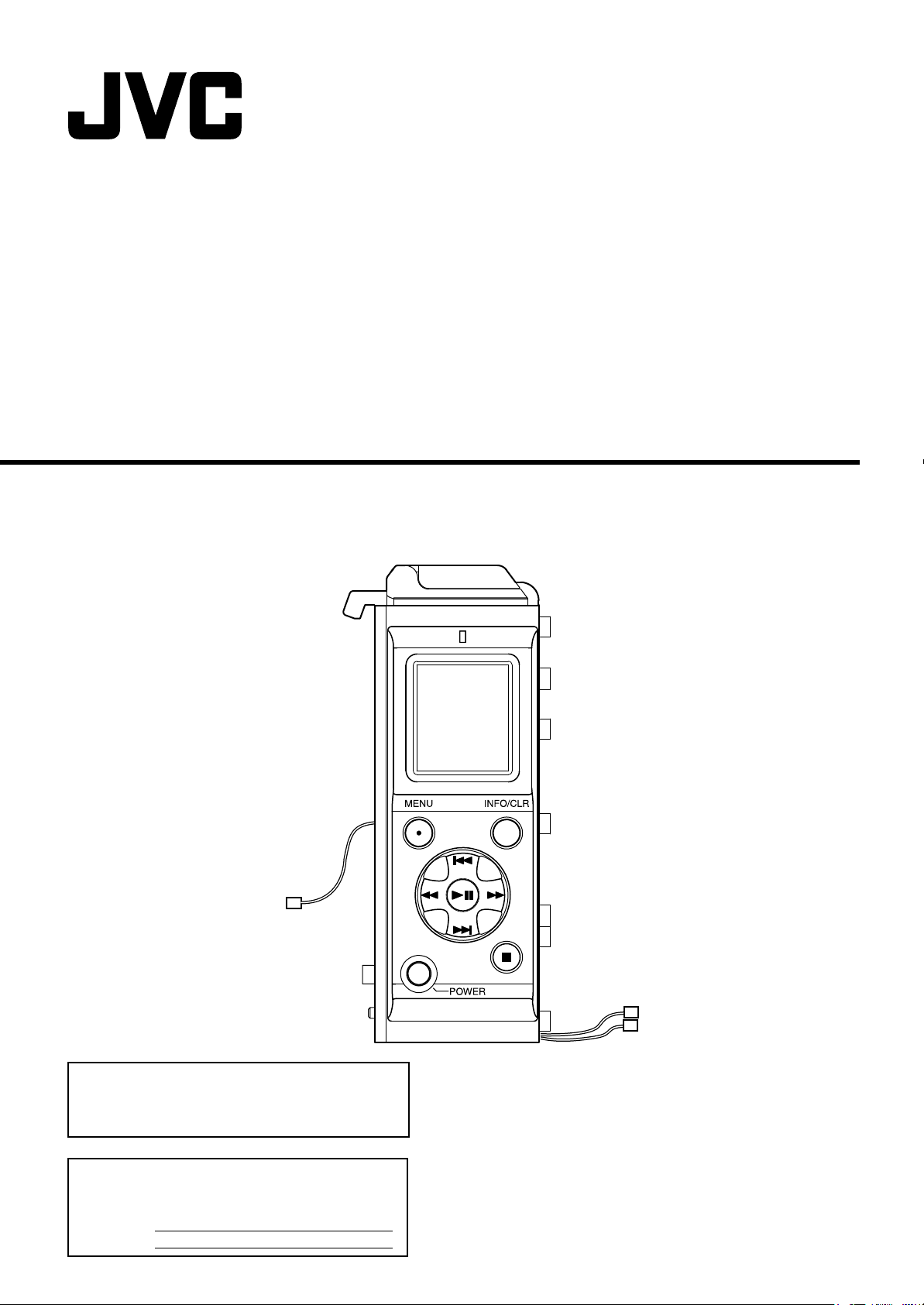
Name and Function of Parts
M
L
K
J
I
H
G
A Access lamp
Displays the status of the SxS memory card.
Light off : SxS memory card is not inserted
Green light : Data in the card is not being accessed
Red light : Data is currently being accessed (e.g.,
recording, playback or formatting in progress)
● Before removing the SxS memory card, make sure that the
access lamp lights up in green color.
LCD panel
B
Displays the status, clip selection and menu screens.
(A Page 5, 10, 11)
emo:
● The contrast and backlight settings of the LCD panel can
be specified on the [LCD] setting screen of the menu
screen.
“LCD panel contrast and backlight settings” (A Page 12)
C [MENU] button
Displays the menu screen. Press this button again to restore
the original screen display.
D
[REV]button
● Fast reverses the selected clip.
● When the Time Code, Date/Time or Clip Name setting
screen is displayed, use this button to select a setting.
E Camcorder connector
To connect the memory recorder with a camcorder, connect
this connector to the memory recorder connector of the
KA-UM100G adapter (sold separately).
F [POWER]button
Turns On/Off the power of the memory recorder. To do so,
press and hold the button for at least one second.
G
[NEXT] button
● Skips the currently selected clip to the next clip.
● When the clip selection screen is displayed, use this
button to select a clip to play back.
● When the menu screen is displayed, use this button to
select a menu item or setting value.
H
Battery connector
For connecting to the battery adapter connector of the
camcorder.
I
[STOP] button
● Stops recording or playback.
● When the menu screen is displayed, press this button to
return to the menu screen without altering the settings.
J
[FWD] button
● Fast forwards the selected clip.
● When the Time Code, Date/Time or Clip Name setting
screen is displayed, use this button to select a setting.
K
[PLAY/STILL]button
● Pauses or starts playback.
● When the menu screen is displayed, press this button to
confirm an item or setting value selection.
L
[INFO/CLR] button
● Switches the clip information display. (A Page 5)
● When the utility execution screen is displayed, use this
button to execute a process. On other setting screens,
pressing this button restores the default settings.
M
[PREV] button
● Skips to the beginning of the selected clip or the previous
clip.
● When the clip selection screen is displayed, use this
button to select a clip to play back.
● When the menu screen is displayed, use this button to
select a menu item or setting value.
N
Card slot
Open the cover and insert the SxS memory card.
(A Page 8)
4
Page 8

Getting Started
LCD Panel Displays
During Recording or Stop Mode
Displays the status screen.
A
B
C
D
E
F
A
Modes
--- SxS memory card is not inserted
oSTOP Stop
RREC Recording
WSTBY Standby (pause)
B Remaining capacity
Displays the remaining time (minutes) of the SxS memory card.
C Date
Shows the date of the built-in clock. The month/day/year
display format can be specified on the [CLOCK2]-[DATE
STYLE] screen of the menu screen.
ASetting the Date/TimeB (A Page 7, 13)
D
Time
Shows the time of the built-in clock. The time display format
(12-hour/24-hour) can be specified on the [CLOCK2]-[TIME
STYLE] screen of the menu screen.
ASetting the Date/TimeB (A Page 7, 13)
E Video format
Shows the video format selected on the [SYSTEM] screen of
the menu screen.
“Video format settings” (A Page 12)
Time code/User bit
F
Displays the time code or user bit to be recorded. Press the
[INFO/CLR] button to toggle the display.
00:00:00:00 : Time code
0F 0F 0F 0F : User bit
emo:
● The time code display differs depending on whether non
drop frame or drop frame mode has been selected in the
[DROP FRAME] setting.
Non drop frame mode 00:00:00:00
Drop frame mode 00:00:00:00
G Total number of clips
Displays the total number of clips recorded in the SxS
memory card.
Clip name
H
Displays the name of the clip that is going to be recorded.
The clip name can be specified on the [CLIP NAME] screen
of the menu screen. “Changing clip name or resetting the clip
number” (A Page 13)
G
Card protect mark
H
emo:
● A ANO CARDB message is shown when an SxS memory
card is not inserted.
●
A ACARD PROTECTB mark is shown before the clip if
the write-protect switch of the SxS memory card is turned
on.
During Playback Mode
Displays the clip selection screen.
I
J
K
L
M
I
Modes
WS Still IPPlaying
NF1 Fast forward
NF2 Fast forward
J Video format
Displays the video format of the selected clip.
“Video format settings” (A Page 12)
K
Clip name
● The clip indicated by the cursor ( ) is the selected clip.
● A ANO CLIPB message is shown when no clip is found.
mark A check mark ( ) appears before clips
ok mark Appears after the clip name. You can
L Playback position bar
Displays the progress of the currently played clip in the form
of a bar.
“Memory recorder’s time code settings” (A Page 12)
M Clip information
Displays various information related to the selected clip.
Press the [INFO/CLR] button to toggle the clip information
display.
00:00:00:00 : Playback time code
0F 0F 0F 0F : Playback user bit
RD 09/07/08: Date on which clip is recorded
RT 11:11:11 : Time on which clip is recorded
Dr 00:10:00 : Clip length (duration) (hour:minute:second)
Note:
● The playback time code value is not an accurate
representation. Use it as a guide for the playback position.
Selected clip/Total number of clips
N
(low speed)
(high speed)
that are playable.
specify the Aok markB on the [OK CLIP]
screen of the menu screen.
“Menu screen’s [OK CLIP] settings”
(A Page 12)
(month/day/year)
(hour:minute:second)
OR1 Fast reverse
OR2 Fast reverse
N
(low speed)
(high speed)
5
Page 9

Setup
Attaching the Memory Recorder to a Camcorder
Check the IEEE1394 connection method before attaching
the memory recorder to the camcorder.
For details, please refer to AConnecting IEEE1394B
(A Page 7)
Note:
● The KA-MR100G adapter (sold separately) is required to
attach the memory recorder to a camcorder.
emo:
● Two different types of battery adapters, manufactured by
IDX and Anton Bauer respectively, are available,
depending on the country/region where the camcorder is
purchased.
1 Remove the battery from the camcorder
2 Remove the battery adapter from the camcorder
Follow the steps illustrated in A _ C below to remove the
battery adapter, followed by the plate (for IDX adapters only)
and rubber sheet from the camcorder.
Rubber sheet
(included with the camcorder)
C Remove screw B (x4)
Screw B
Plate (for IDX
adapters only)
B Remove connector (x2)
emo:
● Battery adapters manufactured by Anton Bauer do not
come with a plate.
Battery adapter
Connector
Screw A
A Remove screw A
(x4)
Screw
A
Battery adapter
for Anton Bauer
4 Attach the memory recorder to the KA-UM100G
adapter
Align the screw holes at the back of the KA-UM100G adapter
with the holes on the rubber sheet. Next, follow the steps
illustrated in A _ D to attach the memory recorder.
B Set the hook to the guide
KA-UM100G
adapter
Recess
Rubber sheet
(included with the
memory recorder)
Note:
Guide
Connector A
A Connect
connector A
Hook
Memory recorder
(KA-UM100G)
D Mount the
Screws
screws (x2)
Connector B
C Connect
connector B
● Store the connection wires and connectors properly so that
they do not protrude from the groove or recess.
5 Attach the battery adapter to the memory
recorder
Align the screw holes at the back of the memory recorder
with the holes on the rubber sheet. Next, follow the steps
illustrated in A _ C to attach the rubber sheet, plate (for IDX
adapters only) and battery adapter.
Rubber sheet
(included with the camcorder)
A Mount screw B (x4)
Screw B
Battery adapter
C Mount screw A (x4)
Screw A
Screw A
3 Attach the KA-UM100G adapter (sold separately)
to the camcorder
Align the screw holes at the back of the camcorder with the
holes on the rubber sheet. Next, follow the steps illustrated in
A _ B to attach the KA-UM100G adapter.
Rubber sheet
(included with KA-UM100G)
Note:
● Store the connection wires and connectors properly so that
they do not protrude from the groove or recess.
KA-UM100G adapter
Screws
B Mount the
screw (x4)
Connector A Connect the
Recess
connector (x2)
Plate (for IDX
adapters only)
B Connect the connector (x2)
Note:
Connector
Battery
adapter for
Anton Bauer
● Store the connection wires and connectors properly so that
they do not protrude from the groove or recess.
emo:
● Battery adapters manufactured by Anton Bauer do not
come with a plate.
6 Attach the battery to the camcorder
Note:
● Do not use the battery that cannot be connected with this
product.
For details, please refer to the instruction manual of the
camcorder.
6
Page 10

Setup
Connecting IEEE1394
There are 2 ways to connect the IEEE1394.
Connecting via IEEE1394 Cable
● Connect the IEEE1394 cable to the KA-UM100G adapter
and the IEEE1394 terminal of the camcorder.
● Set the [INT/EXT] switch to AEXTB.
[INT/EXT] switch
KA-UM100G adapter
IEEE1394 cable
emo:
● When the switch is set to [INT], signal input and output is
disabled.
● For information on where to purchase an IEEE1394 cable,
please consult our authorized dealers.
Connection via Internal Wiring
Changes need to be made to the internal wire connections of
the camcorder.
emo:
●
When making a connection with the switch set to [INT], it is
necessary to alter the internal wire connections of the
camcorder. For details, please consult our authorized dealers.
● When making a connection with internal wiring, the
IEEE1394 terminal of the adapter is disabled.
[INT/EXT]
Switch
INT
EXT
● For recording data to or playing data from the
SxS memory card.
●
When the switch is set to [INT], the IEEE1394
terminal on the camcorder is disabled.
● For connecting the IEEE1394 terminal on the
camcorder to a computer or other devices.
● When the switch is set to [EXT], the internal
connection between the memory recorder
and the camcorder is disabled.
Description
Turning On/Off the Power
Turning On the Power
1
Set the [POWER] switch of the camcorder to “On”
2 Press and hold down the [POWER] button of the
memory recorder for at least one second
●
The power of the memory recorder turns on. After a message
indicating
panel for several seconds, the status screen is displayed.
emo:
●
It is necessary to set the built-in clock immediately after
purchasing this product or when it has not been used for a
prolonged period of time (three months or longer). After the
power of the memory recorder turns on, a message
indicating
seconds. Next, the [CLOCK1] setting screen is automatically
displayed. ASetting the Date/TimeB (APage 7)
A
KA-MR100 POWER ONB appears on the LCD
A
CLOCK SETUP MENUB appears for several
Turning Off the Power
1 Press and hold down the [POWER] button of the
memory recorder for at least one second
● The power of the memory recorder turns off.
emo:
● You can turn off the power of the memory recorder using
the [POWER] switch of the camcorder by setting [DRHD100 A.OFF] on the OTHERS[2/2] menu screen of the
GY-HD200/HD250 series camcorder to AOnB.
Note:
● Make use of a battery to supply power to the memory
recorder. Power cannot be supplied from the DC INPUT
terminal of the camcorder.
Setting the Date/Time
Set the time of the built-in clock on the [CLOCK1] setting
screen of the menu screen.
[PLAY/STILL]
[PREV] button
[REV] button
<[CLOCK1] Setting Screen>
<Buttons to use>
1 Select the item to set (ATIME ZONEB, ADATEB or
ATIMEB)
● Press the [PREV] or [NEXT] button to select an item.
● After making a selection, press the [PLAY/STILL] or [FWD]
button to confirm.
2 Set the respective items
Set the items listed in the table below.
emo:
● Be sure to set the ATIME ZONEB before setting the
ADATEB and ATIMEB”.
● The memory recorder does not support daylight savings
time.
Item Description
For setting the time difference with the
UTC (Universal Time Coordinate). The
values of the ADATEB and ATIMEB items
TIME ZONE
DATE For setting the date (month/day/year).
TIME For setting the time (hour:minute:second).
● Press the [PREV] or [NEXT] button to select a value,
followed by using the [PLAY/STILL] button to confirm the
selection.
● When setting DATE, press the [FWD] or [REV] button to
jump between month, day, and year. When setting TIME,
press the same button to jump between hour, minute and
second.
will be automatically adjusted when this
item is altered.
AUTC Time Difference Chart by RegionB
(A Page 17)
3 Press the [MENU] button to return to the status
screen
button
[FWD] button
[STOP] button
[NEXT] button
7
Page 11

Inserting/Removing the SxS Memory Card
Note:
● This product does not support the USB interface
ExpressCard. Use a recommended SxS memory card.
(ASpecificationsB A Page 16)
● Do not insert the SxS memory card in the reverse
direction. The card slot is designed such that the card
cannot be inserted in the reverse direction. Do not force
the card into the card slot as this will cause malfunction.
Removing the SxS Memory Card
Note:
● Do not remove the SxS memory card when the memory
recorder lights up in red. Before removing the card, make
sure that the access lamp lights up in green color.
1 Slide the tab of the card slot cover horizontally to
open the cover
2 Press the [EJECT] button at the side of the slot
to unlock
3 Press [EJECT] button again, and remove the SxS
memory card
Inserting the SxS memory card
1 Slide the tab of the card slot cover horizontally to
open the cover
2 Insert the SxS memory card into the card slot
● Insert the card with the label facing you as illustrated
below.
● The access lamp lights up in red. When the card is ready
to be used, the light turns green.
SxS memory card
Card slot cover
Label
Open tab
3 Close the card slot cover
emo:
● If a AFORMATB message appears on the LCD panel,
make sure to format (initialize) the card using the memory
recorder. (“Menu screen’s [MEDIA]-[FORMAT] settings”
(A Page 13)
Note:
● SxS memory cards that are formatted using another
product cannot be used on this memory recorder.
Write-protect Switch of SxS Memory Card
To disable recording or deletion of video clips to or from the
SxS memory card so as to protect the recorded clips, set the
write-protect switch at the side of the SxS memory card to
“WP”. When using a write-protected SxS memory card, a
message indicating AWRITE PROTECT!B will appear on the
status screen of the LCD panel for about three seconds. For
details, please refer to the instruction manual of the SxS
memory card.
Note:
● Do not operate the write-protect switch of the SxS memory
card when it is inserted into the memory recorder.
SxS memory card
[EJECT] button
Card slot cover
Open tab
4 Close the card slot cover
Maximum Recording Time of SxS Memory Card
The maximum recording time of an SxS memory card varies
according to the format of the input signals as shown in the
table below.
When using a 32 GB SxS memory card
Mode Video Format
HD1 720 (50p/25p/60p/30p/24p) Approx. 180 mins
HD2 1080 (50i/60i) Approx. 140 mins
emo:
● The values in the table are for reference and are not
guaranteed values. These are not the maximum possible
duration during continuous recording. The maximum
duration for continuous recording when the battery is fully
charged varies according to the battery type.
Max. Recording
Time
8
Page 12

Operation
Recording Video Images of the Camcorder Using the Memory Recorder
To record video images of the camcorder using the memory
recorder, operate using the REC trigger button on the
camcorder. Each time a recording is started and stopped, a
clip is created in the SxS memory card.
Settings Prior to Recording
Before recording, it is necessary to configure the camcorder
and memory recorder settings.
䡵 Camcorder settings
1 Set to the ACAMB mode using the [CAM/VTR]
button
2 Set the [IEEE1394] switch to the AHDVB end
● The memory recorder does not support the DV format.
3 Set the video format (e.g., 720/60p)
● Set according to the video format settings of the memory
recorder.
emo:
● The GY-HD200 (B) series camcorders can record in the
1080 format. Check the name plate on the camcorder.
4 Select a method for recording to the SxS
memory card
● Select the method to record to the SxS memory card from
the [1394 REC TRIGGER] item of the OTHERS[2/2] menu
screen.
Setting Recording Method
Records only to the cassette tape of the
OFF
SYNCRO For hybrid recording
SPLIT Records only to the SxS memory card
SERIES For series recording
T For details, please refer to the instruction manual of the
camcorder.
䡵 Memory recorder settings
For procedures to set the menu screen, refer to page 11.
1 Set the video format according to the camcorder
setting
● Set the RESOLUTION and FRAME/RATE under the
[SYSTEM] settings on the menu screen. (A Page 12)
2 Set the time code recording method for the SxS
memory card
● Set the three items below on the [TC SET1] setting screen
of the menu screen. (A Page 12)
Setting item Description
TC SOURCE For setting the source of the time code
GENERATOR
DROP
FRAME
Set the preset time code and user bit values on the [TC
SET2] setting screen of the menu screen. (A Page 13)
camcorder.
T Data is not recorded in the SxS
memory card.
For setting the run mode of the time code
generator of the memory recorder.
For selecting either ANON DROPB or
ADROPB frame (enabled only when the
frame rate is set to 60 or 30.)
Recording to the SxS Memory Card
● When the memory recorder is in the play mode, press the
[STOP] button to stop playback.
● There are three REC trigger buttons on the camcorder (on
the lens, at the side, and on the handle). The REC trigger
button to enable recording to the SxS memory card varies
according to the [1394 REC TRIGGER] settings.
● A ATRIGGER TO HDVB message is shown on the
camcorder panel display when the REC trigger button is
pressed.
䡵 Hybrid recording with cassette tape (when the
ASYNCROB setting is enabled)
For recording data to both the cassette tape of the
camcorder and the memory recorder.
1
Press any one of the REC trigger buttons on the
lens, at the side, or on the handle of the camcorder
to start recording to the SxS memory card
2 Press the REC trigger button of the camcorder to
switch between the recording and standby
modes
3 Press the [STOP] button on the memory recorder
to stop recording
emo:
● When a cassette tape is not inserted into the camcorder,
data will only be recorded to the SxS memory card.
䡵 Recording only to the SxS memory card (when
the ASPLITB setting is enabled)
For recording to the SxS memory card by pressing the REC
trigger button at the side of the camcorder.
1 Press the REC trigger button at the side of the
camcorder to start recording to the
SxS memory
card
2
Press the REC trigger button of the camcorder to
switch between the recording and standby modes
3 Press the [STOP] button on the memory recorder
to stop recording
䡵 Series recording (when the ASERIESB setting is
enabled)
Recording to the SxS memory card starts automatically
when the remaining capacity of the cassette tape falls below
three minutes.
1
Press any one of the REC trigger buttons on the
lens, at the side, or on the handle of the camcorder
to start recording to the
● Recording to the SxS memory card starts automatically
when the remaining capacity of the cassette tape falls
below three minutes.
cassette tape
2 Press the [STOP] button on the memory recorder
to stop recording
emo:
● When there is no remaining space left on the SxS memory
card, a ACARD FULL!B message will appear for about
three seconds.
Camcorder Panel Display
Remaining time
Memory recorder
When connected: White color
During recording: Red color
1394 REC TRIGGER mode
R: OFF Y: SYNCRO
<Camcorder’s
STATUS 0 screen>
R: SPLIT F: SERIES
When connected: Red blinking
During recording: Red color
9
Page 13

Playing Video Images Recorded in the Memory Recorder
To play back video images recorded by the memory
recorder, select a clip from the clip selection screen on the
LCD panel of the memory recorder. The selected video clip
is played back on the LCD monitor and viewfinder of the
camcorder.
emo:
● Before playing back video images recorded by the memory
recorder, stop the playback of the cassette tape in the
camcorder.
● Images on the LCD monitor and viewfinder of the
camcorder may be distorted when in the Still and Fast
forward/Fast reverse modes.
2 Press the [NEXT] or [PREV] button to select a
clip to play
● Select a clip that has a check mark.
● To play back a clip without a check mark, it is necessary to
configure the camcorder and memory recorder according
to the video format settings, which are displayed when the
clip is selected.
3 Press the [PLAY/STILL] button to start playback
● The video clip is played back on the LCD monitor and
viewfinder of the camcorder.
● The progress bar on the LCD panel of the memory
recorder moves to indicate the current playback position.
● Press the [PLAY/STILL] button during playback to switch
to the still mode. Press the button again to resume
playback.
emo:
● When multiple video clips are stored in the SxS memory
card, the playable clips are played back continuously in
sequence. Playback switches to the still mode at the end
of the last clip.
Settings Prior to Playback
Before playing, it is necessary to configure the camcorder
and memory recorder settings.
䡵 Camcorder settings
1 Set to the AVTRB mode using the [CAM/VTR]
button
2 Set the [IEEE1394] switch to the AHDVB end
䡵 Memory recorder settings
For procedures to set the menu screen, refer to page 11.
1 Set the video format
● Set the RESOLUTION and FRAME/RATE under the
[SYSTEM] settings on the menu screen. (A Page 12)
Note:
● Set according to the format settings of the camcorder.
Playback cannot be executed if the camcorder and
memory recorder settings are different from each other.
Playing a Clip from the SxS Memory Card
If the memory recorder is in the standby mode, press the
[STOP] button on the recorder to switch to the stop mode.
[PREV]
button
[REV]
button
LCD Panel>
<Buttons to use>
Normal playback
1 Press the [PLAY/STILL] button
emo:
● Playable clips are indicated by a check mark ( ) at the
front of their names.
● The clip indicated by the cursor ( ) is the selected clip.
ALCD Panel DisplaysB (A Page 5)
[PLAY/STILL] button
[FWD] button
[STOP] button
[NEXT]button
4 Press the [STOP] button to stop playback of the
clip
The LCD panel display switches to the status screen.
Fast forward/Fast reverse
Fast forwards or fast reverses the selected clip. It will switch
to still mode at the end or beginning of the selected clip. To
switch to the still mode during fast forward or fast reverse,
press the [PLAY/STILL] button.
䡵 Pressing the [FWD] button in the still mode,
during playback or fast reverse
Switches to the low speed fast forward (F1) mode. Press the
[FWD] button again to switch to the high speed fast forward
(F2) mode.
䡵 Pressing the [REV] button in the still mode,
during playback or fast forward
Switches to the low speed fast reverse (R1) mode. Press the
[REV] button again to switch to the high speed fast reverse
(R2) mode.
Skip
Skips to the next or previous playable clip.
䡵 Pressing the [NEXT] button in the still mode or
during fast reverse
Doing so switches automatically to the still mode after
skipping to the beginning of the next clip. Pressing the button
twice switches to the still mode after skipping to the
beginning of the second clip from the current one.
䡵 Pressing the [PREV] button in the still mode or
during fast reverse
Pressing this button during playback of the clip switches
automatically to the still mode after skipping to the beginning
of the selected clip. Pressing the button again skips to the
beginning of the previous clip and remains in the still mode.
䡵 Pressing the [NEXT] button during playback or
fast forward
Pressing the button starts playback automatically from the
beginning of the next clip. Pressing the button twice starts
playback from the beginning of the second clip from the
current one.
䡵 Pressing the [PREV] button during playback or
fast forward
Pressing this button during playback of the clip starts
playback automatically from the beginning of the selected
clip. Pressing the button at the beginning of the clip starts
playback from the beginning of the previous clip.
10
Page 14

Menu
Setting the Menu Screen
● [NUMBER] of the [CLIP NAME] setting screen
● [FORMAT] and [RESTORE] of the [MEDIA] setting screen
● [ALL RESET] of the [OTHERS] setting screen
Utility item being selected
[MENU] button
[PREV]button
[REV] button
[INFO/CLR] button
[PLAY/STILL] button
[FWD] button
[STOP] button
[NEXT] button
Procedures for Setting Values
1 Press the [MENU] button
Menu screen
Setting item
Current setting value
2 Move the cursor ( ) to the item to be set by
pressing the [NEXT] or [PREV] button
3 Press the [PLAY/STILL] or [FWD] button
Current selected setting item
Cursor
Current selected setting value
Set using [PLAY/STILL] button
Return to the menu screen without setting
using [STOP] button
4 Move the cursor ( ) to the value to be set by
pressing the [NEXT] or [PREV] button
5 Press the [PLAY/STILL] button to confirm the
setting
● The menu screen appears after the setting is changed.
emo:
● When the setting screen is displayed, pressing the [STOP]
or [REV] button returns the display to the menu screen
without altering the setting value.
6 Press the [MENU] button to exit the menu screen
display
Procedures for Executing the Utilities
1 Select a menu item to display the execution
screen of the corresponding utility
The different utility items are shown below.
● [NOW CLIP] and [ALL CLIP] of the [DELETE] setting
screen
● [ALL OK] and [ALL NONE] of the [OK CLIP] setting screen
Execute with [INFO/CLR] button
Return to the menu screen without
setting using [STOP] button
2 Press the [INFO/CLR] button to execute the
selected item
● When [FORMAT] or [RESTORE] is completed,
ACOMPLETEB appears on the LCD display.
● When [FORMAT] or [RESTORE] is in progress,
AEXECUTEB appears on the LCD display. If failure occurs,
AERRORB is displayed.
● After the execution message appears, the display returns
to the menu screen.
● All operations are disabled during execution of a utility.
emo:
● Press the [STOP] button to return to the menu screen
without executing the selected item.
Procedures for Setting Time Code/ User Bit Preset, Clip Name and Date/Time
1 Select a menu item from Time Code/User Bit
Preset, Clip Name and Date/Time
● Time Code Preset/User Bit Preset :
[TC PRESET]/[UB PRESET] of the [TC SET2] setting
screen
● Clip Name setting :
[PREFIX] of the [CLIP NAME] setting screen
● Date/Time setting :
[DATE]/[TIME] of the [CLOCK1] setting screen
Reset to A00:00:00:00B with [INFO/CLR]
button
Current selected setting item
Set using [PLAY/STILL] button
Return to the menu screen without setting
using [STOP] button
emo:
● During setting of the time code, user bit or time, pressing
the [INFO/CLR] button sets all digits to “00”. In the clip
name setting, the default clip name is shown.
2 Press the [FWD] or [REV] button to select the
item to set
3 Alter the value of the selected item by pressing
the [NEXT] or [PREV] button
4 Press the [PLAY/STILL] button to confirm the
new value
● The menu screen appears after the setting is changed.
emo:
● When the setting screen is displayed, pressing the [STOP]
button returns the display to the menu screen without
altering the setting value.
11
Page 15

Menu Screen Configurations and Functions
Values indicated in parentheses in the table below are default
settings.
Setting Item Setting Values Functions
SYSTEM For setting the format of the video to be recorded or played back. Make sure
RESOLUTION (720), 1080 For setting the resolution.
FRAME/RATE RESOLUTION: When 720 is set
LCD For setting the contrast and backlight of the memory recorder’s LCD panel.
CONTRAST MAX, +4, +3, +2, +1, (0), -1, -2,
BACKLIGHT OFF
DELETE For deleting a clip.
NOW CLIP NO
ALL CLIP NO
OK CLIP For important clips or clips that you do not want to delete, specify them as AOK
NOW CLIP NONE
ALL OK NO
ALL NONE NO
TC SET1 For configuring settings related to the time code of the memory recorder.
TC SOURCE (INT)
GENERATOR FREE
DROP
FRAME
(60p), 30p, 50p, 25p, 24p
RESOLUTION: When 1080 is set
(60i), 50i
-3, -4, MIN
(ON)
AUTO
YES
YES
OK
YES
YES
EXT
(RECRUN)
REGEN
(NON DROP)
DROP
that the settings are consistent with those of the camcorder. Otherwise,
recording and playback cannot be executed.
For setting the frame rate. The configurable frame rate may vary according to
the [RESOLUTION] setting.
For adjusting the contrast.
OFF : Backlight is turned off at all times.
ON : Backlight is turned on at all times.
AUTO: Backlight turns on when the buttons are operated. Light turns off
automatically about five seconds after the buttons are operated.
● This function is disabled when recording is in progress.
● Clips indicated with an Aok markB cannot be deleted.
Deletes the currently selected clip when in the play mode. Deletes the clip that
is last recorded when in the stop or standby mode.
YES : Delete clips. (Press the [INFO/CLR] button.)
NO : Do not delete clips. (Press the [STOP] button.)
Deletes all clips.
YES : Delete clips. (Press the [INFO/CLR] button.)
NO : Do not delete clips. (Press the [STOP] button.)
clipB. Upon specifying a clip as an AOK clipB, an Aok markB will appear to the
right of the clip name on the clip selection screen.
For specifying a selected clip as an AOK clipB when in the playback mode. For
specifying the clip that is last recorded as an AOK clipB when in the stop or
standby mode.
NONE: Do not specify an A OK clipB. (Press the [PLAY/STILL] button.)
OK : Specify an AOK clipB. (Press the [PLAY/STILL] button.)
For specifying all clips as AOK clipsB.
YES : Specify as AOK clipsB. (Press the [INFO/CLR] button.)
NO : Retain current settings. (Press the [STOP] button.)
Cancels all AOK clipB specifications.
YES : Cancel AOK clipB specifications. (Press the [INFO/CLR] button.)
NO : Retain current settings. (Press the [STOP] button.)
For selecting the source of the time code.
INT : The time code runs according to the value of the memory recorder’s
time code generator.
EXT : The time code runs according to the value of the time code from the
camcorder.
When [EXT] is selected, make sure to set the [TC GENE.] switch of the
camcorder to AFREEB.
For selecting the run mode of the time code generator.
● Setting is enabled when [TC SOURCE] is set to AINTB.
FREE : The time code runs according to the preset value in the free run
RECRUN : The time code runs according to the preset value when in the
REGEN : The time code runs continuously according to the last time code on
For selecting the non drop frame or drop frame mode.
● Setting is enabled when [TC SOURCE] is set to AINTB.
● Setting is enabled when the frame rate is set to 60 or 30.
NON DROP : Non drop frame mode
DROP : Drop frame mode
mode.
recording mode.
the SxS memory card.
12
Page 16

Menu
Setting Item Setting Values Functions
TC SET2 For presetting the time code generator of the memory recorder.
TC PRESET (00:00:00:00) _ 23:59:59:29
UB PRESET (00:00:00:00) _ FF FF FF FF For presetting the user bit. (8 digits)
CLIP NAME For specifying the first four characters of the clip name before recording, or
PREFIX (Last three digit of the serial
NUMBER
RESET
CLOCK1 For configuring settings related to the clock of the memory recorder.
TIME ZONE UTC-12:00 _
DATE (--/--/--) For setting the date (month/day/year). The last two digits of the western calendar
TIME (--:--:--) For setting the time (hour:minute:second).
CLOCK2 For setting the date or time display mode.
DATE STYLE YY/MM/DD
TIME STYLE 12
MEDIA For setting processes related to the SxS memory card.
FORMAT YES
RESTORE YES
OTHER For configuring settings related to the control buttons and menus of the memory
OPERATION (UNLOCK)
ALL RESET YES
or
(00:00:00:00) _ 23:59:59:24
number + K)
YES
NO
(UTC-05:00) _ UTC+14:00
(MM/DD/YY)
DD/MM/YY
(24)
NO
NO
LOCK
NO
The number of frames that can be specified are as shown below, depending on
the setting of the frame rate. (e.g., when the frame rate is 60, you can specify the
number of frames up to a value of 58.)
Frame rate 60 50 30 25 24
Number of frames 58 48 29 24 23
resetting the clip number.
● An eight-digit clip name is automatically configured.
● Serial numbers are automatically appended as the last four digits whenever a
clip is created. Serial numbers are automatically appended even when SxS
memory card is replaced or after changing the first four characters of the clip
name at APREFIXB.
For specifying the first four characters of the clip name.
(Usable characters: A to Z, a to z, 0 to 9, -, _)
The default clip name is set as the “last three digits of the serial number + K”.
Example: If the serial number is 00001234, then the default clip name is 234K.
You can reset the clip number (0001) after changing the clip name at APREFIXB.
If clips already exist on the SxS memory card, the smallest available number will
be used.
Example: If 0001 exists on the SxS memory card, then 0002 will be used.
YES : Reset clip number. (Press the [INFO/CLR] button.)
NO : Do not reset clip number. (Press the [STOP] button.)
For setting the time difference with the UTC (Universal Time Coordinate).
AUTC Time Difference Chart by RegionB (A Page 17)
When the setting of this item is altered, the [DATE]/[TIME] values below will be
automatically adjusted.
is used.
Press the [INFO/CLR] button to display the default setting.
Press the [INFO/CLR] button to display the default setting.
For specifying the display style of the date.
● Altering the setting of this item also changes the [DATE] display mode on the
[CLOCK1] setting screen.
YY/MM/DD : Year/Month/Day
MM/DD/YY : Month/Day/Year
DD/MM/YY : Day/Month/Year
For specifying the display style of the time.
● Altering the setting of this item also changes the [TIME] display mode on the
[CLOCK1] setting screen.
12 : 12-hour display (AM/PM display)
24 : 24-hour display
Starts the formatting (initialization) of the SxS memory card.
● When formatting is performed, all clips stored inside the SxS memory card will
be cleared.
YES : Format. (Press the [INFO/CLR] button.)
NO : Do not format. (Press the [STOP] button.)
Scans the SxS memory card and makes attempts to restore damaged clips.
● However, success of the restore process is not guaranteed.
YES : Execute. (Press the [INFO/CLR] button.)
NO : Do not execute. (Press the [STOP] button.)
recorder.
You can disable the button control of the memory recorder to avoid misoperations
during shooting.
UNLOCK: Enables all buttons.
LOCK : Button control is disabled, with the exception of the following.
● Record/Standby (REC trigger button of the camcorder)
● Menu screen display ([MENU] button)
● Power On ([POWER] button)
For resetting the menu settings of the memory recorder to the default values.
YES : Restore default settings. (Press the [INFO/CLR] button.)
NO : Do not restore default settings. (Press the [STOP] button.)
13
Page 17

Others
Warning Messages
When warning messages appear on the LCD panel, take the
following actions.
WRITE
PROTECT!
Message Description
CLOCK
SETUP
MENU
WRITE
PROTECT!
CARD FULL! Appears when there is no more space left
OPERATION
LOCK !
Warning Messages
Appears when the clock is not set.
Action: Set the clock when the [CLOCK1]
setting screen appears.
Appears when the write-protect switch of
the SxS memory card is set to the “WP”
end.
Action: Set the write-protect switch to AOffB
before recording or deleting a clip.
on the SxS memory card.
Action: Take any of the following actions.
● Use an SxS memory card with sufficient
space.
● Delete unwanted clips or format the card
to create space.
Appears when buttons other than the
[MENU] button is pressed with the
[OPERATION] menu set to ALOCKB.
Action: Change the [OPERATION] menu
setting to AUNLOCKB.
Error Messages
Card Error Messages
When an SxS memory card incompatible with the memory
recorder is detected, an AERROR CARD!B message and a
message indicating the cause of the card error will appear
alternately at the first line of the LCD panel display. (For
approximately two seconds) When an error message
appears, take the following actions.
Message Description
NO
SUPPORT!
FORMAT! Appears when the card has already been
CARD
CHANGE
RESTORE ! Appears when the clip may be damaged.
Card error message appears when the following operations
are performed.
● When an SxS memory card is inserted
● When power is turned on with an SxS memory card
inserted
䡵 When in the stop, standby or still mode
Status screen (stop or standby)
Appears when a media not supported by
the memory recorder is inserted.
Action: Replace it with a recommended
SxS memory card.
formatted by another device.
Action: Execute AFORMATB using this
memory recorder.
“Menu screen’s [MEDIA]->[FORMAT]
settings” (A Page 13)
Appears when errors are found in the clip.
Action: Execute ARESTOREB or
AFORMATB using this memory recorder. If
doing so does not eliminate the error, it
may be due to malfunction of the SxS
memory card. Replace the SxS memory
card.
Action: Execute ARESTOREB using this
memory recorder.
Battery and Signal Error Messages
An error message appears at the first line of the LCD panel
display when the battery is weak or when there is an input
signal error. When an error message appears, take the
following actions.
Message Description
BAT.
ALARM !
SHUT
DOWN !
NO SIGNAL !
(*1)
Other
SIGNAL (*1)
(*1) Appears during the recording or stop mode.
Appears when the remaining battery level
is insufficient.
Action: Charge the battery.
Appears immediately before the battery
runs out completely. The memory recorder
will shut down a few seconds after the
message is displayed.
Action: Charge the battery.
Appears when there is no signal input.
Action: Check the connection of the
IEEE1394 cable and the camcorder
settings.
Appears when the format of input signals is
different from that of the memory recorder.
Action: Make sure that the memory
recorder settings are consistent with those
of the camcorder. (A Page 9)
<LCD Panel>
Clip selection screen (still)
<LCD Panel>
䡵 When in the menu screen display
<LCD Panel>
14
Page 18

Others
Troubleshooting
Symptom Cause(s)Actions Refer to
Power does not turn onPower is supplied from the DC INPUT
Unable to record or
play clip
Recording does not
start
Unable to play clip The camcorder is set to the ACAMB mode. Set to the AVTRB mode using the [CAM/VTR] button. A Page 10
No response when a
button is pressed
Access lamp does not
turn on
SxS memory card
cannot be used
Error message
appears on the
camcorder panel
display
terminal of the camcorder.
Only the power of the camcorder is turned
AOnB.
Remaining battery level is insufficient. Charge the battery. A Page 14
The IEEE1394 cable is not connected. Connect a GY-HD200/HD250 series camcorder to the
The [INT/EXT] switch setting of the
KA-UM100G adapter is inappropriate.
The video formats of the camcorder and
memory recorder are not consistent with
each other.
The [IEEE1394] switch of the camcorder is
set to the ADVB end.
The camcorder is set to the AVTRB mode. Set to the ACAMB mode using the [CAM/VTR] button. A Page 9
The [1394 REC TRIGGER] item on the
OTHERS[2/2] menu screen of the
camcorder is set to AOFFB or ASERIESB.
The memory recorder is set to the playback
mode.
The write-protect of the SxS memory card
is enabled.
There is no space left on the SxS memory
card.
The cassette tape is currently being played
back.
A clip without the check mark (v) is
selected.
The memory recorder is in the recording or
standby mode.
The clip may be damaged. Execute ARESTOREB using this memory recorder. A Page 14
The [OPERATION] menu is set to ALOCKB. Change the [OPERATION] menu setting to AUNLOCKB. A Page 14
A multiple number of buttons are pressed
at the same time, or the same button is hit
repeatedly.
The SxS memory card is not completely
inserted into the card slot.
The SxS memory card is inserted with the
label facing the opposite direction.
A SxS memory card that is formatted by
another device is used.
A media that is not supported is inserted. Replace it with a recommended SxS memory card. A Page 14
The clip is faulty. Execute ARESTOREB or AFORMATB using this memory
ADR-HD100 POWER ?B appears when the
memory recorder is not powered on or is
not connected.
AHDD NO 1394 SIGNALB appears if the
camcorder is set to the “CAM” mode when
the memory recorder is in playback mode.
AHDD SPACE LOWB appears when the
space on the SxS memory card is
insufficient or an SxS memory card is not
inserted.
Attach the battery. The power of the memory recorder
cannot be supplied from the DC INPUT terminal of the
camcorder.
It is necessary to turn on the power of the memory recorder
at the same time.
KA-UM100G adapter using an IEEE1394 cable.
● Set to AEXTB during normal use. (When IEEE1394
connection is made internally without the use of an
external cable, set to AINTB.
● If the ANO SIGNALB message does not disappear even
if the setting is correct, set the switch again to select the
setting. If the message remains displayed, turn off and
on the power again.
Ensure that the video format of the camcorder and memory
recorder are consistent with each other.
Set the [IEEE1394] switch to the AHDVB end.
If the ANO SIGNALB message does not disappear even
after setting to AHDVB, set the switch again. If the message
remains displayed, turn off and on the power again.
Set [1394 REC TRIGGER] to ASYNCROB or ASPLITB.
When this is set to ASERIESB, recording starts when the
remaining capacity of the cassette tape falls below three
minutes.
Press the [STOP] button to stop playback. A Page 9
Set the write-protect switch to AOffB before recording or
deleting a clip.
Use an SxS memory card that has sufficient space. A Page 14
Stop playback of the cassette tape before playing back
data on the SxS memory card.
Set the camcorder and memory recorder according to the
video format displayed when a clip is selected.
Press the [STOP] button to stop playback. A Page 10
Insert a short pause between each button operation.
Make sure that the SxS memory card is fully inserted into
the slot.
Identify the face of the SxS memory card with the label,
and make sure that the card is correctly oriented before
inserting.
Execute AFORMATB using this memory recorder. A Page 13
recorder. If doing so does not eliminate the error, replace it
with a recommended SxS memory card.
Connect and turn on the power of the memory recorder. A Page 6
Set the camcorder to the AVTRB mode. A Page 10
Use an SxS memory card that has sufficient space.
A Page 7
A Page 7
A Page 7
A Page 7
A Page 9
A Page 9
A Page 10
A Page 9
A Page 14
A Page 10
A Page 10
^
A Page 8
A Page 8
A Page 14
A Page 7
^
15
Page 19

Specifications
䡵 Media slot
Supported media SxS memory card
Number of slot 1 slot
Interface ExpressCard/34-compliant
(supports only PCI Express, USB is not
supported)
䡵 Video format
Recording format MP4
Recording time HD1 mode: Approx. 180 mins
HD2 mode: Approx. 140 mins
(recording time when using a 32 GB card)
File system FAT32 (SxS format)
Maximum file size 4 GB
OS compatibility Windows XP/Vista/Mac OS/X
䡵 Input signal format
Video <HD1 mode>
MPEG-2 (MP@H-14)
720/50p/25p/60p/30p/24p (8 bit 19.5 Mbps
CBR)
<HD2 mode>
MPEG-2 (MP@H-14)
1080/50i/60i (8 bit 25 Mbps CBR)
Audio 16 bit/48 kHz 2ch, 384 kbps (MP2)
Time code signal Compliant with SMPTE/EBU standard
䡵 Overall
Power supply DC 12 V (DC 10.5 V to 17 V)
Power consumption 6 W
External
dimensions
Weight 0.42 kg
Operating
temperature
Operating humidity 30 % to 80 % RH
Storage
temperature
Storage humidity 85 % RH and below
90 mm x 57 mm x 131 mm (W x D x H)
0 ⬚C to 40 ⬚C
-20 ⬚C to 60 ⬚C
䡵 Others
Accessories Instruction manual ⳯1, Rubber sheet ⳯1,
Connectable HD
camcorders
Optional products KA-UM100G adapter (Mount kit for
Recommended
products
Warranty (USA and CANADA only)⳯1,
CD-ROM⳯1,
GY-HD200 and GY-HD250 series
connecting a GY-HD200/GY-HD250 series
HD camcorder to a memory recorder.)
<SxS memory card>
SBP-8 (8 GB), SBP-16 (16 GB) and
SBP-32 (32 GB)
<IEEE1394 cable> CFS-6R016R09-07 etc.
Please consult your authorized dealers.
Dimension [Unit: mm (inch)]
KA-MR100G KA-UM100G adapter (sold separately)
Weight: 0.145 kg
● Power, temperature, humidity and environment
conforming to KA-MR100G.
T Specifications and appearance of this memory recorder and related products are subject to change for further improvement
without prior notice.
16
Page 20

UTC Time Difference Chart by Region
Setting Values Time Zone Setting Values Time Zone
UTC+14:00 UTC 00:00 Greenwich
UTC+13:30 UTC-00:30
UTC+13:00 UTC-01:00 Azores
UTC+12:30 UTC-01:30
UTC+12:00 New Zealand UTC-02:00 Mid-Atlantic
UTC+11:30 Norfolk Island UTC-02:30
UTC+11:00 Solomon Islands UTC-03:00 Buenos Aires
UTC+10:30 Lord Howe Is. UTC-03:30 Newfoundland
UTC+10:00 Guam UTC-04:00 Halifax
UTC+09:30 Darwin UTC-04:30
UTC+09:00 Tokyo UTC-05:00 New York
UTC+08:30 UTC-05:30
UTC+08:00 Beijing UTC-06:00 Chicago Denver
UTC+07:30 UTC-06:30
UTC+07:00 Bangkok UTC-07:00 Denver
UTC+06:30 Rangoon UTC-07:30
UTC+06:00 Dhaka UTC-08:00 Los Angels
UTC+05:30 Bombay UTC-08:30
UTC+05:00 Islamabad UTC-09:00 Alaska
UTC+04:30 Kabul UTC-09:30 Marquesa Islands
UTC+04:00 Abu Dhabi UTC-10:00 Hawaii
UTC+03:30 Tehran UTC-10:30
UTC+03:00 Moscow UTC-11:00 Midway Island
UTC+02:30 UTC-11:30
UTC+02:00 Eastern Europe UTC-12:00 Kwajalein
UTC+01:30
UTC+01:00 Central Europe
UTC+00:30
KA-MR100G Memory Recorder
© 2009 Victor Company of Japan, Limited
LST0838-001A
 Loading...