

Page 1
SERVICE MANUAL
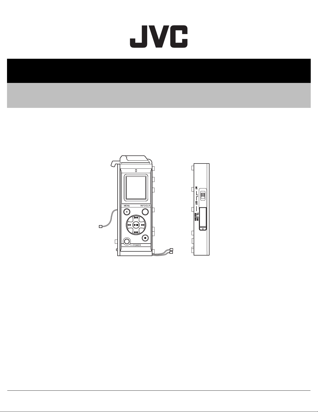
MEMORY RECORDER, ADAPTER
HC027<Rev.001>20095SERVICE MANUAL
KA-MR100G, KA-MR100G(A),
KA-UM100G
KA-MR100G KA-UM100G
* When the GY-HM700 series is connected, KA-UM100G is
COPYRIGHT © 2009 Victor Company of Japan, Limited
unnecessary because it connects it directly with KA-MR100G(A).
TABLE OF CONTENTS
1 PRECAUTION. . . . . . . . . . . . . . . . . . . . . . . . . . . . . . . . . . . . . . . . . . . . . . . . . . . . . . . . . . . . . . . . . . . . . . . . . 1-3
1.1 SAFETY PRECAUTIONS . . . . . . . . . . . . . . . . . . . . . . . . . . . . . . . . . . . . . . . . . . . . . . . . . . . . . . . . . . 1-3
2 SPECIFIC SERVICE INSTRUCTIONS . . . . . . . . . . . . . . . . . . . . . . . . . . . . . . . . . . . . . . . . . . . . . . . . . . . . . . 1-5
3 DISASSEMBLY . . . . . . . . . . . . . . . . . . . . . . . . . . . . . . . . . . . . . . . . . . . . . . . . . . . . . . . . . . . . . . . . . . . . . . . 1-5
3.1 KA-MR100G. . . . . . . . . . . . . . . . . . . . . . . . . . . . . . . . . . . . . . . . . . . . . . . . . . . . . . . . . . . . . . . . . . . . . 1-5
3.2 KA-UM100G. . . . . . . . . . . . . . . . . . . . . . . . . . . . . . . . . . . . . . . . . . . . . . . . . . . . . . . . . . . . . . . . . . . . . 1-8
4 ADJUSTMENT . . . . . . . . . . . . . . . . . . . . . . . . . . . . . . . . . . . . . . . . . . . . . . . . . . . . . . . . . . . . . . . . . . . . . . . . 1-9
4.1 EQUIPMENT NECESSARY FOR ADJUSTMENT. . . . . . . . . . . . . . . . . . . . . . . . . . . . . . . . . . . . . . . . 1-9
4.2 27MHz ADJUSTMENT. . . . . . . . . . . . . . . . . . . . . . . . . . . . . . . . . . . . . . . . . . . . . . . . . . . . . . . . . . . . . 1-9
4.3 FIRMWARE WRITING. . . . . . . . . . . . . . . . . . . . . . . . . . . . . . . . . . . . . . . . . . . . . . . . . . . . . . . . . . . . 1-10
5 TROUBLESHOOTING . . . . . . . . . . . . . . . . . . . . . . . . . . . . . . . . . . . . . . . . . . . . . . . . . . . . . . . . . . . . . . . . . 1-11
5.1 KA-MR100G/KA-UM100G Internal Cable Connection. . . . . . . . . . . . . . . . . . . . . . . . . . . . . . . . . . . . 1-11
COPYRIGHT © 2009 Victor Company of Japan, Limited
No.HC027<Rev.001>
2009/5
Page 2
SPECIFICATION
KA-MR100G KA-MR100G(A)
Media slot
Supported media SxS memory card
Number of slot 1 slot
Interface ExpressCard/34-compliant
(supports only PCI Express, USB is not supported)
Video format
Recording format MP4
Recording time HD1 mode: Approx. 180 mins
HD2 mode: Approx. 140 mins
(recording time when using a 32 GB card)
File system FAT32 (SxS format)
Maximum file size 4 GB
OS compatibility Windows XP/Vista/Mac OS/X
Input signal format
Video <HD1 mode>
MPEG-2 (MP@H-14)
720/50p/25p/60p/30p/24p (8 bit 18.3 Mbps CBR)
<HD2 mode>
MPEG-2 (MP@H-14)
1080/50i/60i (8 bit 25 Mbps CBR)
Audio 16 bit/48 kHz 2ch, 384 kbps (MP2)
Time code signal Compliant with SMPTE/EBU standard
Overall
Power supply DC 12 V (DC 10.5 V to 17 V)
Power consumption 6 W
External dimensions 90 mm × 57 mm × 131 mm (W × D × H)
Weight 0.42 kg
Operating temperature 0ºC to 40ºC
Operating humidity 30 % to 80 % RH
Storage temperature -20ºC to 60ºC
Storage humidity 85 % RH and below
Others
Accessories Instruction manual × 1, Rubber sheet × 1, Warranty (USA and CANADA only) × 1, CD-ROM × 1
Connectable HD camcorders GY-HD200, GY-HD250 series. GY-HD200, GY-HD250, GY-HM700 series.
Optional products KA-UM100G adapter (Mount kit for connecting a GY-HD200/GY-HD250 series HD camcorder to a memory re-
corder.)
Recommended products <SxS memory card>
SBP-8 (8 GB), SBP-16 (16 GB) and SBP-32 (32 GB)
<IEEE1394 cable> CFS-6R016R09-07 etc. Please consult your authorized dealers.
SOFTWARE NO. SPL1044-V1-00 SPL1044-V2-00
SYS 0100 0200
MBE 0100 0200
MBEB 0100 0100
HQ mode: Approx. 100 mins
HD1 mode: Approx. 180 mins
HD2 mode: Approx. 140 mins
(recording time when using a 32 GB card)
<HQ mode>
MPEG-2 (MP@HL)
1080/60i/30p/50i/25p/24p
720/60p/30p/50p/25p/24p(8 bit 35 Mbps VBR)
<HD1 mode>
MPEG-2 (MP@HL / MP@H-14)
720/60p/30p/50p/25p/24p(8 bit 18.3 Mbps CBR)
<HD2 mode>
MPEG-2 (MP@H-14)
1080/60i/50i(8 bit 25 Mbps CBR)
KA-UM100G
Weight 0.145 kg
External dimensions 79.5 mm × 23 mm × 119.5 mm (W × D × H)
• Specifications and appearance of this unit are subject to change for improvement without prior notice.
1-2 (No.HC027<Rev.001>)
Page 3
SECTION 1
r
PRECAUTION
1.1 SAFETY PRECAUTIONS
Prior to shipment from the factory, JVC products are strictly inspected to conform with the recognized product safety and electrical codes of the countries in which they are to be
sold.However,in order to maintain such compliance, it is equally
important to implement the following precautions when a set is
being serviced.
1.1.1 Precautions during Servicing
(1) Locations requiring special caution are denoted by labels
and inscriptions on the cabinet, chassis and certain parts of
the product.When performing service, be sure to read and
comply with these and other cautionary notices appearing
in the operation and service manuals.
(2) Parts identified by the symbol and shaded ( ) parts
are critical for safety.
Replace only with specified part numbers.
NOTE :
Parts in this category also include those specified to
comply with X-ray emission standards for products
using cathode ray tubes and those specified for
compliance with various regulations regarding spurious radiation emission.
(3) Fuse replacement caution notice.
Caution for continued protection against fire hazard.
Replace only with same type and rated fuse(s) as specified.
(4) Use specified internal wiring. Note especially:
• Wires covered with PVC tubing
• Double insulated wires
• High voltage leads
(5) Use specified insulating materials for hazardous live parts.
Note especially:
• Insulation Tape
• PVC tubing
•Spacers
• Insulation sheets for transistors
• Barrier
(6) When replacing AC primary side components (transformers,
power cords, noise blocking capacitors, etc.) wrap ends of
wires securely about the terminals before soldering.
Fig.1-1-1
(7) Observe that wires do not contact heat producing parts
(heatsinks, oxide metal film resistors, fusible resistors, etc.)
(8) Check that replaced wires do not contact sharp edged or
pointed parts.
(9) When a power cord has been replaced, check that 10-15
kg of force in any direction will not loosen it.
Power cord
cathode ray tubes and other parts with only the specified
parts. Under no circumstances attempt to modify these circuits.Unauthorized modification can increase the high voltage value and cause X-ray emission from the cathode ray
tube.
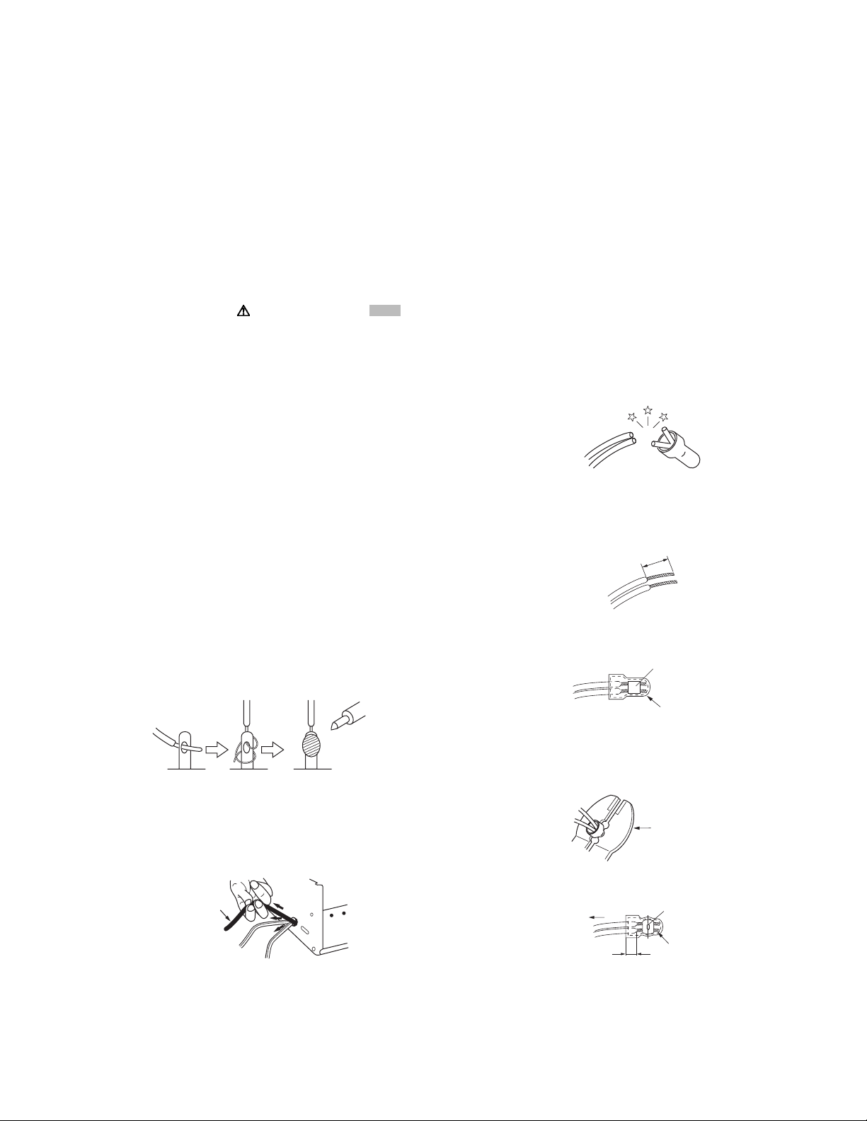
(12) Crimp type wire connector In such cases as when replac-
ing the power transformer in sets where the connections
between the power cord and power trans former primary
lead wires are performed using crimp type connectors, if
replacing the connectors is unavoidable, in order to prevent
safety hazards, perform carefully and precisely according
to the following steps.
• Connector part number :E03830-001
• Required tool : Connector crimping tool of the proper
type which will not damage insulated parts.
• Replacement procedure
a) Remove the old connector by cutting the wires at a
point close to the connector.Important : Do not reuse a connector (discard it).
cut close to connector
Fig.1-1-3
b) Strip about 15 mm of the insulation from the ends
of the wires. If the wires are stranded, twist the
strands to avoid frayed conductors.
15 mm
Fig.1-1-4
c) Align the lengths of the wires to be connected. In-
sert the wires fully into the connector.
Metal sleeve
Connector
Fig.1-1-5
d) As shown in Fig.1-1-6, use the crimping tool to
crimp the metal sleeve at the center position. Be
sure to crimp fully to the complete closure of the
tool.
1
.2
2.0
5.5
5
Crimping tool
Fig.1-1-6
e) Check the four points noted in Fig.1-1-7.
Not easily pulled free
Crimped at approx. cente
of metal sleeve
Fig.1-1-2
(10) Also check areas surrounding repaired locations.
(11) Products using cathode ray tubes (CRTs) In regard to such
products, the cathode ray tubes themselves, the high voltage circuits, and related circuits are specified for compliance with recognized codes pertaining to X-ray emission.
Consequently, when servicing these products, replace the
Conductors extended
Wire insulation recessed
more than 4 mm
Fig.1-1-7
(13) Battery replacement caution notice.
CAUTION RISK OF EXPLOSION IF BATTERY IS REPLACED BY AN INCORRECTIVE TYPE.
DISPOSE OF USED BATTERIES ACCORDING TO THE
INSTRUCTIONS.
(No.HC027<Rev.001>)1-3
Page 4
1.1.2 Safety Check after Servicing
Examine the area surrounding the repaired location for damage
or deterioration. Observe that screws, parts and wires have been
returned to original positions, Afterwards, perform the following
tests and confirm the specified values in order to verify compliance with safety standards.
(1) Insulation resistance test
Confirm the specified insulation resistance or greater between power cord plug prongs and externally exposed
parts of the set (RF terminals, antenna terminals, video and
audio input and output terminals, microphone jacks, earphone jacks, etc.).See table 1 below.
(2) Dielectric strength test
Confirm specified dielectric strength or greater between
power cord plug prongs and exposed accessible parts of
the set (RF terminals, antenna terminals, video and audio
input and output terminals, microphone jacks, earphone
jacks, etc.). See Fig.1-1-11 below.
(3) Clearance distance
When replacing primary circuit components, confirm specified clearance distance (d), (d') between soldered terminals, and between terminals and surrounding metallic
parts. See Fig.1-1-11 below.
d
Chassis
d'
Power cord
primary wire
Fig.1-1-8
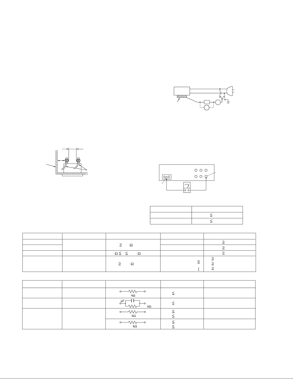
(4) Leakage current test
Confirm specified or lower leakage current between earth
ground/power cord plug prongs and externally exposed accessible parts (RF terminals, antenna terminals, video and
audio input and output terminals, microphone jacks, earphone jacks, etc.).
Measuring Method : (Power ON) Insert load Z between
earth ground/power cord plug prongs and externally exposed accessible parts. Use an AC voltmeter to measure
across both terminals of load Z. See Fig.1-1-9 and following Fig.1-1-12.
ab
Externally
exposed
accessible part
Z
V
c
A
Fig.1-1-9
(5) Grounding (Class 1 model only)
Confirm specified or lower grounding impedance between
earth pin in AC inlet and externally exposed accessible
parts (Video in, Video out, Audio in, Audio out or Fixing
screw etc.).Measuring Method:
Connect milli ohm meter between earth pin in AC inlet and
exposed accessible parts. See Fig.1-1-10 and grounding
specifications.
AC inlet
Earth pin
Exposed accessible part
Milli ohm meter
Grounding Specifications
Region
USA & Canada
Europe & Australia
Grounding Impedance (Z
Z 0.1 ohm
Z 0.5 ohm
)
Fig.1-1-10
AC Line Voltage
100 V
100 to 240 V
110 to 130 V
110 to 130 V
200 to 240 V
Region
Japan
USA & Canada
Europe & Australia
Insulation Resistance (R
R 1 M /500 V DC
1 M R 12 M /500 V DC
R 10 M /500 V DC
)
Dielectric Strength
AC 1 kV 1 minute
AC 1.5 kV 1 minute
AC 1 kV 1 minute
AC 3 kV 1 minute
AC 1.5 kV 1 minute
(
Class
(
Class
Clearance Distance (d), (d'
d, d' 3 mm
d, d' 4 mm
d, d' 3.2 mm
d 4 m m
)
d' 8 m m (Power cord
d' 6 m m (Primary wire
)
Fig.1-1-11
AC Line Voltage
100 V
110 to 130 V
110 to 130 V
220 to 240 V
Region
Japan
USA & Canada
Europe & Australia
Load Z
1
0.15
1.5
2
50
Leakage Current (i)
i 1 mA rms
i 0.5 mA rms
i 0.7 mA peak
i 2 mA dc
i 0.7 mA peak
i 2 mA dc
a, b, c
Exposed accessible parts
Exposed accessible parts
Antenna earth terminals
Other terminals
Fig.1-1-12
NOTE :
These tables are unofficial and for reference only. Be sure to confirm the precise values for your particular country and locality.
)
)
)
1-4 (No.HC027<Rev.001>)
Page 5
SECTION 2
SPECIFIC SERVICE INSTRUCTIONS
This service manual does not describe SPECIFIC SERVICE INSTRUCTIONS.
SECTION 3
DISASSEMBLY
3.1 KA-MR100G
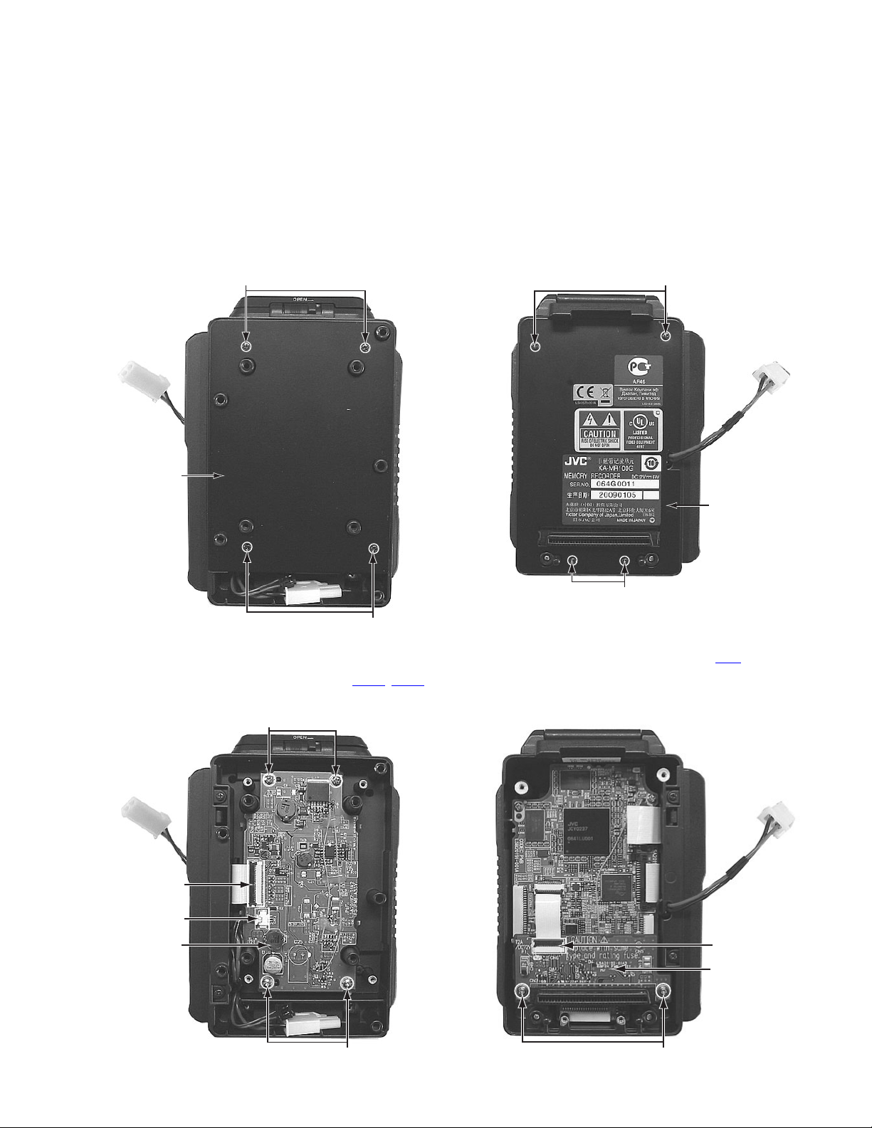
3.1.1 Removing the PS board (See figure 1, figure 2)
(1) Remove the four screws A attaching the plate R.
A
Plate R
A
Fig.1
(2) Remove the four screws B attaching the PS board.
(3) Disconnect the wires from each connector CN12, CN13 on
the PS board.
B
3.1.2 Removing the 68PIN board, CODEC board, SxS board
(See figure 3, figure 4, figure 5, figure 6)
(1) Remove the four screws C attaching the plate F.
C
Plate F
C
Fig.3
(2) Disconnect the wire from connector CN6
board.
(3) Remove the two screws D attaching the 68PIN board, and
then remove it.
on the 68PIN
CN13
CN12
PS Board
Fig.2
CN6
68PIN Board
B
D
Fig.4
(No.HC027<Rev.001>)1-5
Page 6

(4) Disconnect the wires from each connector CN13
the CODEC board.
(5) Remove the four screws E attaching the CODEC board,
and then remove it.
, CN21 on
E
CN21
CN13
3.1.3 Removing the guide unit (See figure 7, figure 8, figure
9)
• Remove the SxS board.
(1) Remove the two screws G attaching the guide unit with
SxS board.
G
CODEC Board
NOTE:
E
Be careful not to damage the CN28 when
removing or attaching the CODEC board.
Fig.5
(6) Remove the four screws F attaching the SxS board, and
then remove it.
F
SxS Board
Fig.7
(2) Remove the guide unit from the SxS board by sliding the
guide unit to the direction of the arrow.
G
Guide unit
Fig.8
NOTE:
Attention at installation.
Locked surely
1-6 (No.HC027<Rev.001>)
Fig.6
SxS Board
Come into contact
Fig.9
F
Page 7

3.1.4 Removing the OPE board (See figure 10, figure 11,
figure 12, figure 13)
• Remove the plate R and plate F.
(1) Remove the four screws H attaching the OPE cover as-
sembly.
(2) Remove the two tabs and then remove the OPE cover as-
sembly.
(3) Disconnect the wire from connector CN21
board.
on the CODEC
(4) Remove the two screws J attaching the OPE board, and
then remove it.
CODEC Board
CN21
OPE Cover assembly
Fig.10
H
H
Ta b
H
J
OPE Board
Fig.12
NOTE:
When replacing the LCD, do not straighten the FPC that
was once bent. Repeating the bend and straighten operation may cause backlight failures.
LCD
Ta b
H
OPE Cover assembly
Fig.11
Do not straighten the FPC
that was once bent.
Fig.13
(No.HC027<Rev.001>)1-7
Page 8

3.2 KA-UM100G
3.2.1 Removing the UMA board (See figure 14, figure 15,
figure 16)
(1) Remove the four screws K attaching the plate R.
K
Plate R
K
Fig.14
(3) Disconnect the wires from each connector CN102
on the UMA board, and then remove it.
UMA Board
CN104
CN102
Fig.16
, CN104
(2) Remove the three screws L attaching the UMA board.
L
UMA Board
L
Fig.15
1-8 (No.HC027<Rev.001>)
Page 9

SECTION 4
ADJUSTMENT
4.1 EQUIPMENT NECESSARY FOR ADJUSTMENT
Instrument Condition and part number
Frequency counter Readable in 8 or more digits, and must be calibrated. Constancy of 0.1ppm/1 x 10
at 0ºC to 40ºC.
JIG board Part number: KSJ1705
Connecting cable Part number: KS44291
Battery (Recommended) U Model: Anton Bauer Dionic90
E Model: IDX Endura-7
SD card Minimum 16 MB or more
4.2 27MHz ADJUSTMENT
When the CODEC Board is replaced, this adjustment is required.
-7
or more
4.2.1 Connection
Connect the JIG board, connecting cable,
• The GY-HD200/250 series supplies power only by the battery. And, after it charges it full, the battery is adjusted.
• As for the GY-HM700 series, the supply from the DC power supply is possible.
*1 NOTE:
Please connect it so as not to damage 1 pin and 20 pins of CN24 on the CODEC board when the cable is connected while keeping
the connector parallel.
4.2.2 Adjustment procedure
Measuring point TP1 on the JIG Board
Adjustment level 27MHz ± 15Hz (26.999985MHz to 27.000015MHz)
(1) While pressing the [] button and the [INFO/CLR] button, press the [MENU] button to display the adjustment menu screen.
(2) Select [AJUST] using the [] button.
䂓 --AJUST---
> PLL
㪢㪘㪄㪤㪩㪈㪇㪇㪞
128
*1
and the frequency counter as shown in the figure below.
㪞㪥㪛
㪫㪧㪈
㩷㪡㪠㪞㩷㪙㫆㪸㫉㪻
㪝㫉㪼㫈㫌㪼㫅㪺㫐㩷㪺㫆㫌㫅㫋㪼㫉
(3) Press the [] button.
(4) Change the value using the [] or [] button to adjust the frequency of TP1 on the JIG board to the adjustment level.
䂓PLL
> ADJUST 130
27䋮0000 129
MHz > 128
127
126
(5) Press the [] button to set the adjustment result.
(6) Press and hold the [POWER] button for more than one second to turn the power OFF.
(No.HC027<Rev.001>)1-9
Page 10

4.3 FIRMWARE WRITING
NOTE:
The power supply to KA-MR100G is from the battery only. Before starting the firmware writing, make sure the battery is fully charged
to avoid power shortage during the writing. Power shortage during the firmware writing may damage the internal ICs.
NOTE:
Make sure to take SxS card out beforehand.
Before starting firmware writing, make sure the IEEE1394 connection is disconnected.
Internally connected: Switch the KA-UM100G connection from [INT] to [EXT].(GY-HD200/250)
Externally connected: Unplug the cable, or switch the KA-UM100G connection from [EXT] to [INT].(GY-HD200/250)
(1) Download the firmware file from JS-NET.
(2) Save the downloaded firmware file to an SD card.
(3) The GY-HD200/250 series supplies power by the battery with which it charges full. As for GY-HM700, the supply from the DC
power supply of 12V is possible.
(4) Remove the two screws from the bottom of KA-MR100G, then remove the cover.
(5) Turn ON the power of KA-MR100G, then insert the SD card into the SD card slot.
(6) Firmware writing starts automatically, and finishes in about two minutes.
(7) The writing operation can be checked by the LED (D11) on the CODEC Board.
LED
(D11)
Bottom view
Flashes Writing
Lights up Writing finished
Turns off Writing error
• If a writing error occurs, perform the above procedure again.
4.3.1 How to check the firmware version
Push both MENU button and INFO/CLR button simultaneously more than 3 seconds.
NOTE:
It inserts it carefully in the direction
of the SD card.
SYS Ver=4A09
MBE Ver=409B
MBEB Ver=0100
PACK Ver=409A
FPGA Ver=0100
SxSF Ver= - - - SxSC Ver= - - - -
Version display
1-10 (No.HC027<Rev.001>)
Page 11

SECTION 5
TROUBLESHOOTING
5.1 KA-MR100G/KA-UM100G Internal Cable Connection
Note:
• After this modification, the IEEE1394 connector of KA-UM100G becomes no communication available.
• “Internal connected cable” is unnecessary in the GY-HM700 series.
5.1.1 Remove Left side cover
• Refer to see service manual (No.HC014) 1-1 and 1-2.
5.1.3 Remove the battery mount plate
(The figure is Anton type for U-model. IDX type is mounted for
E-model.)
(1) Remove four screws.
Fig.1
5.1.2 Open the CON cover
(1) Remove the 5 screws and take out sw cover.
Fig.2
(2) Remove the cable between SW pwb CN54 and DV OUT
pwb CN54.
Fig.5
(2) Remove four screws, and then the PS pwb cover.
Fig.6
<Internal Cable>
WJJ0994-001A-E
12P cable
Connect to CN54 of the SW PWB
Gray 6P cable
*The removed cable is not used.
Fig.3
Fig.4
Blue 6P cable
Connect to CN105 of the KA-UM100G
Connect to CN54 of the DV OUT PWB
Fig.7
(No.HC027<Rev.001>)1-11
Page 12

5.1.4 Install the Internal cable
(1) Remove the four screws.
Fig.8
(2) Pass 12P cable through under the PS PWB.
5.1.5 Install the KA-UM100G
(1) Reinstall the PS PWB cover and tighten four screws.
Fig.12
(2) Connect Battery cable and Battery INFO cable.
12P cable connector
Fig.9
(3) Connect Gray 6P cable connector to SW PWB CN54.
Gray 6P cable connector
Remote PWB CN87
Note.
Gray 6P cable should be wired at back of the
cable of Remote PWB CN87 in order to prevent
from touching fan motor.
Fig.10
(4) Connect Blue 6P cable connector to DV OUT CN54.
Note.
The connector should be placed to the
bottom space.
Fig.13
(3) Connect 12P cable connecter to KA-UM100G.
Note.
Connect 12P cable connecter
firmly by using tweezers etc.
Fig.14
Note.
The cable should be passed through this
position of figure.
1-12 (No.HC027<Rev.001>)
Note.
The cable should be placed in the groove
space of KA-UM100G.
Fig.15
Fig.11
Page 13

5.1.6 Mount KA-MR100G
(1) Connect Battery cable.
(4) Install the rubber sheet.
Fig.19
Fig.16
(2) Attach KA-MR100G to KA-UM100G.
Push the bottom side of KA-MR100G to be locked.
Fig.17
(3) Tighten two screws.
5.1.7 Install the Battery mount plate
(1) Connect Battery cable and Battery INFO cable.
Note.
The connector should be placed to the
bottom space.
Fig.20
(2) Tighten four screws.
Fig.18
5.1.8 Set the [INT/EXT] switch to "INT"
Note.
After this modification, the IEEE1394 connector of
KA-UM100G becomes no communication available.
Fig.21
Set to INT
No communication available through IEEE1394 terminal of KA-UM100G
(No.HC027<Rev.001>)1-13
Page 14

Victor Company of Japan, Limited
PROFESSIONAL SYSTEMS DIVISION
(No.HC027<Rev.001>)
Printed in Japan
VSE
 Loading...