

Page 1
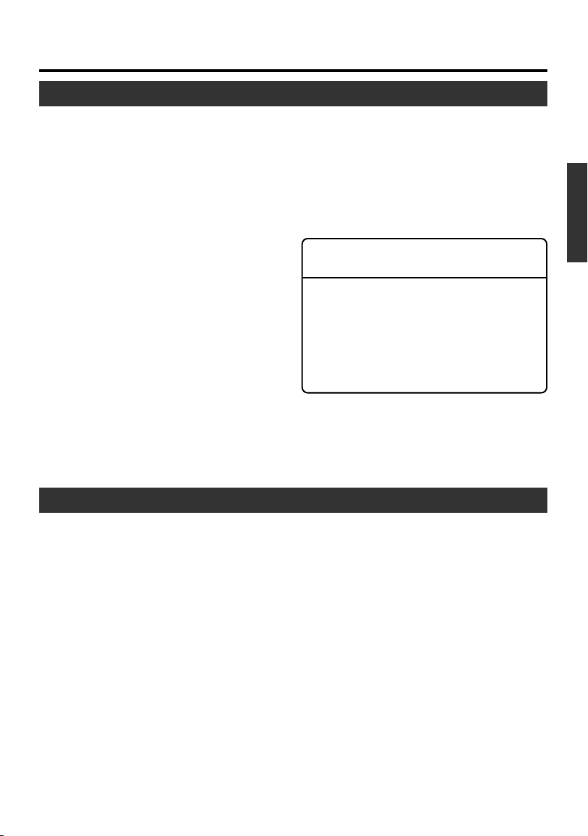
STUDIO KIT
F.f
ft
m
30
1035
15
10
7
2
1.5
5
4
1.2
5.5 10
C16
11
8
MACRO
STUDIO SDI KIT
KA-F5602U
KA-F5603U
PROMPTER
RM
OUTPUT
EnglishJapanese
INSTRUCTIONS
BREAKER
DC INPUT
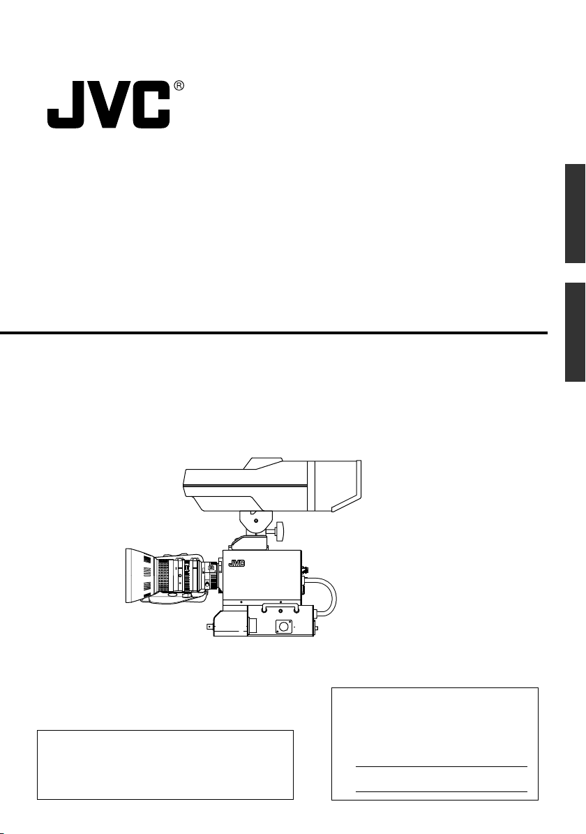
*Illustration with optional lens
and viewfinder attachments.
This instructions book is made from 100 %
recycled paper.
Thank you for purchasing this JVC product.
Before operating this unit, please read the
instructions carefully to ensure the best
possible performance.
For Customer Use:
Enter below the Serial No. which is
located on the cabinet. Retain this
information for future reference.
Model No. KA-F5602U/KA-F5603U
Serial No.
LWT0176-001B
Page 2

1. Read all of these instructions.
2. Save these instructions for later use.
3. All warnings on the product and in the operating instructions should be adhered to.
4. Unplug this appliance system from the wall outlet before cleaning. Do not use liquid cleaners or
aerosol cleaners. Use a damp cloth for cleaning.
5. Do not use attachments not recommended by the appliance manufacturer as they may cause hazards.
6. Do not use this appliance near water – for example, near a bathtub, washbowl, kitchen sink, or
laundry tub, in a wet basement, or near a swimming pool, etc.
7. Do not place this appliance on an unstable cart, stand, or table. The appliance
may fall, causing serious injury to a child or adult, and serious damage to the
appliance.
Use only with a cart or stand recommended by the manufacturer, or sold with the
appliance.
Wall or shelf mounting should follow the manufacturer’s instructions, and should
use a mounting kit approved by the manufacturer.
An appliance and cart combination should be moved with care. Quick stops,
excessive force, and uneven surfaces may cause the appliance and cart
combination to overturn.
S3125A
8. Slots and openings in the cabinet and the back or bottom are provided for
ventilation, and to insure reliable operation of the appliance and to protect it from overheating, these
openings must not be blocked or covered. The openings should never be blocked by placing the
appliance on a bed, sofa, rug, or other similar surface. This appliance should never be placed near or
over a radiator or heat register. This appliance should not be placed in a built-in installation such as a
bookcase unless proper ventilation is provided.
9. This appliance should be operated only from the type of power source indicated on the marking label.
If you are not sure of the type of power supplied to your home, consult your dealer or local power
company. For appliance designed to operate from battery power, refer to the operating instructions.
10. This appliance system is equipped with a 3-wire grounding type plug (a plug having a third (grounding)
pin). This plug will only fit into a grounding-type power outlet. This is a safety feature. If you are unable
to insert the plug into the outlet, contact your electrician to replace your obsolete outlet. Do not defeat
the safety purpose of the grounding plug.
11. For added protection for this product during a lightning storm, or when it is left unattended and
unused for long periods of time, unplug it from the wall outlet and disconnect the antenna or cable
system. This will prevent damage to the product due to lightning and power-line surges.
12. Do not allow anything to rest on the power cord. Do not locate this appliance where the cord will be
abused by persons walking on it.
13. Follow all warnings and instructions marked on the appliance.
14. Do not overload wall outlets and extension cords as this can result in fire or electric shock.
15. Never push objects of any kind into this appliance through cabinet slots as they may touch dangerous
voltage points or short out parts that could result in a fire or electric shock. Never spill liquid of any
kind on the appliance.
16. Do not attempt to service this appliance yourself as opening or removing covers may expose you to
dangerous voltage or other hazards. Refer all servicing to qualified service personnel.
17. Unplug this appliance from the wall outlet and refer servicing to qualified service personnel under the
following conditions:
a. When the power cord or plug is damaged or frayed.
b. If liquid has been spilled into the appliance.
c. If the appliance has been exposed to rain or water.
d. If the appliance does not operate normally by following the operating instructions. Adjust only
those controls that are covered by the operating instructions as improper adjustment of other
controls may result in damage and will often require extensive work by a qualified technician to
restore the appliance to normal operation.
e. If the appliance has been dropped or the cabinet has been damaged.
f. When the appliance exhibits a distinct change in performance – this indicates a need for service.
18. When replacement parts are required, be sure the service technician has used replacement parts
specified by the manufacturer that have the same characteristics as the original part. Unauthorized
substitutions may result in fire, electric shock, or other hazards.
19. Upon completion of any service or repairs to this appliance, ask the service technician to perform
routine safety checks to determine that the appliance is in safe operating condition.
2
Page 3
SAFETY PRECAUTIONS (FOR USA AND CANADA)
CAUTION
RISK OF ELECTRIC SHOCK
DO NOT OPEN
CAUTION: TO REDUCE THE RISK OF ELECTRIC SHOCK,
WARNING:
TO REDUCE THE RISK OF FIRE OR
ELECTRIC SHOCK, DO NOT EXPOSE THIS
APPLIANCE TO RAIN OR MOISTURE.
This unit should be used with 12 V DC only.
CAUTION:
To prevent electric shocks and fire hazards, DO
NOT use any other power source.
NOTE:
The rating plate (serial number plate) is on this unit.
INFORMATION
This equipment has been tested and found to comply
with the limits for a Class B digital device, pursuant to
Part 15 of the FCC Rules. These limits are designed to
provide reasonable protection against harmful
interference in a residential installation. This equipment
generates, uses, and can radiate radio frequency energy
and, if not installed and used in accordance with the
instructions, may cause harmful interference to radio
communications. However, there is no guarantee that
interference will not occur in a particular installation.
If this equipment does cause harmful interference to
radio or television reception, which can be determined
by turning the equipment off and on, the user is
encouraged to try to correct the interference by one or
more of the following measures:
● Reorient or relocate the receiving antenna.
●
●
● Consult the dealer or an experienced radio/TV
CAUTION
CHANGES OR MODIFICATIONS NOT APPROVED
BY JVC COULD VOID USER’S AUTHORITY TO
OPERATE THE EQUIPMENT.
THIS DEVICE COMPLIES WITH PART 15 OF THE
FCC RULES. OPERATION IS SUBJECT TO THE
FOLLOWING TWO CONDITIONS: (1) THIS DEVICE
MAY NOT CAUSE HARMFUL INTERFERENCE, AND
(2) THIS DEVICE MUST ACCEPT ANY INTERFERENCE RECEIVED, INCLUDING INTERFERENCE
THAT MAY CAUSE UNDESIRED OPERATION.
DO NOT REMOVE COVER (OR BACK).
NO USER-SERVICEABLE PARTS INSIDE.
REFER SERVICING TO QUALIFIED SERVICE PERSONNEL
The lightning flash with arrowhead symbol, within an
equilateral triangle, is intended to alert the user to the
presence of uninsulated “dangerous voltage” within
the product’s enclosure that may be of sufficient
magnitude to constitute a risk of electric shock to
persons.
The exclamation point within an equilateral triangle is
intended to alert the user to the presence of important
operating and maintenance (servicing) instructions
in the literature accompanying the appliance.
Increase the separation between the equipment and receiver.
Connect the equipment into an outlet on a circuit
different from that to which the receiver is connected.
technician for help.
ATTENTION
RISQUE D’ELECTROCUTION
NE PAS OUVRIR
ATTENTION: POUR EVITER TOUT RISQUE D’ELECTROCUTION
SE REFERER A UN AGENT QUALIFIE EN CAS DE PROBLEME.
AVERTISSEMENT:
POUR EVITER LES RISQUES
D’INCENDIE OU D’ELECTROCUTION, NE
PAS EXPOSER L’APPAREIL A
L’HUMIDITE OU A LA PLUIE.
Cet appareil ne doit être utilisé sur 12 V en
courant continu.
ATTENTION:
Afin d’éviter tout resque d’incendie ou
d’électrocution, ne pas utiliser d’autres
sources d’alimentation électrique.
REMARQUE:
La plaque dıidentification (numéro de série) se
trouve sur l’appareil.
INFORMATION (F0R CANADA)
RENSEIGNEMENT (POUR CANADA)
This Class B digital apparatus complies with
Canadian ICES-003.
Cet appareil numérique de la Class B est
conforme à la norme NMB-003 du Canada.
NE PAS OUVRIR LE BOITER.
AUCUNE PIECE INTERIEURE N’EST
A REGLER PAR L’UTILISATEUR.
Le symbole de l’éclair à l’intérieur d’un triangle
équilatéral est destiné à alerter l’utilisateur sur la
présence d’une “tension dangereuse” non isolée
dans le boîtier du produit. Cette tension est suffisante
pour provoquer l’électrocution de personnes.
Le point d’exclamation à l’intérieur d’un triangle
équilatéral est destiné à alerter l’utilisateur sur la
présence d’opérations d’entretien importantes au
sujet desquelles des renseignements se trouvent
dans le manuel d’instructions.
*Ces symboles ne sont utilisés qu’aux Etats-Unis.
English
3
Page 4
SAFETY PRECAUTIONS (FOR EUROPE)
WARNING:
TO REDUCE THE RISK OF FIRE OR ELECTRIC
SHOCK, DO NOT EXPOSE THIS APPLIANCE TO
RAIN OR MOISTURE.
This unit should be used with 12 V DC only.
CAUTION:
To prevent electric shocks and fire hazards, do NOT
use any other power source.
Note:
The rating plate (serial number plate) is on this unit.
CAUTION
To prevent electric shock, do not open the cabinet. No user
serviceable parts inside. Refer servicing to qualified service
personnel.
4
Page 5

This equipment is in conformity with the provisions and protection requirements of the corresponding European Directives. This equipment is designed for professional video appliances
and can be used in the following environments:
5 Residential (including both of the location type class 1 and 2 found in IEC 1000-2-5)
5 Commercial and light industrial (including, for example, theatres)
5 Urban outdoors (based on the definition of location type class 6 in IEC 1000-2-5)
In order to keep the best performance and furthermore for electromagnetic compatibility we
recommend to use cables not exceeding the following lengths:
Port Cable Length
RM Exclusive Cable 100 meters
PROMPTER OUTPUT Coaxial Cable 5 meters
DC INPUT Exclusive Cable 5 meters
SDI OUTPUT Coaxial Cable 5 meters
Caution:
5 Where there are strong electromagnetic waves or magnetism, for example near a radio or
TV transmitter, transformer, motor, etc., the picture and sound may be disturbed. In such a
case, please keep the apparatus away from the sources of the disturbance.
English
5
Page 6

Thank you for purchasing this
KA-F5602U / KA-5603U Studio Kit.
This product is a kit meant for converting JVC’s KY-F560 video camera into a studio camera.
Model designation may differ depending on whether the Studio Kit is equipped with a SDI
(Serial Digital Interface) terminal.
Model
KA-F5602U
KA-F5603U
SDI Output Terminal
Nil
Yes
Main Features
● Equipped with analog 26P camera connector
Connecting to Remote Control Unit RM-P210, which is sold separately, this unit could be
controlled from up to a distance of 100 m away. In this case, power for the camera is
provided by the remote control unit and thus there is no requirement for a separate power
supply for the camera.
● Multi-system output
From the 26P camera connector, besides the composite signal, another video signal
which could be either RGB component, Y/Cb/Cr component, or YC separate signal could
be outputted. (Selectable by menu switch.)
● Possible to install VF-P400 4-inch Viewfinder
● Equipped with intercom terminal
With the use of headset, communications with remote control unit operator is possible.
● Equipped with prompter output terminal
Prompter video from the remote control unit could be outputted in the form of composite
signal.
● H phase and SC phase could be adjusted during synchronization. (Using menu screen)
● Equipped with SDI output terminal (Only for KA-F5603U)
Camera video is output as serial digital video signal (SMPTE259M-compliant).
6
Page 7

Contents
Getting Started
Accessories ........................................................................................................ 8
Related Products used in Conjunction with this Unit ..........................................8
Precautions......................................................................................................... 9
Regarding Gain-lock Signal and adjustment of System Phase ..........................9
Part Names and Functions ...............................................................................10
Installation
System .............................................................................................................. 13
Installation Procedures .....................................................................................14
Mounting KY-F560 Camera on this Unit ........................................................... 14
Mounting the Lens onto the Camera ................................................................ 16
Mounting this Unit onto the Tripod.................................................................... 16
Mounting VF-P400 4-inch Viewfinder on this Unit ............................................17
Connecting RM-P210
Connecting to Remote Control Unit RM-P210 .................................................. 18
Notes to be taken when operating RM-P210.................................................... 20
Menu Screen
“SYSTEM” Menu Screen ..................................................................................21
“DISPLAY” Menu Screen .................................................................................. 22
Others
Specifications ................................................................................................... 23
English
7
Page 8
Getting Started
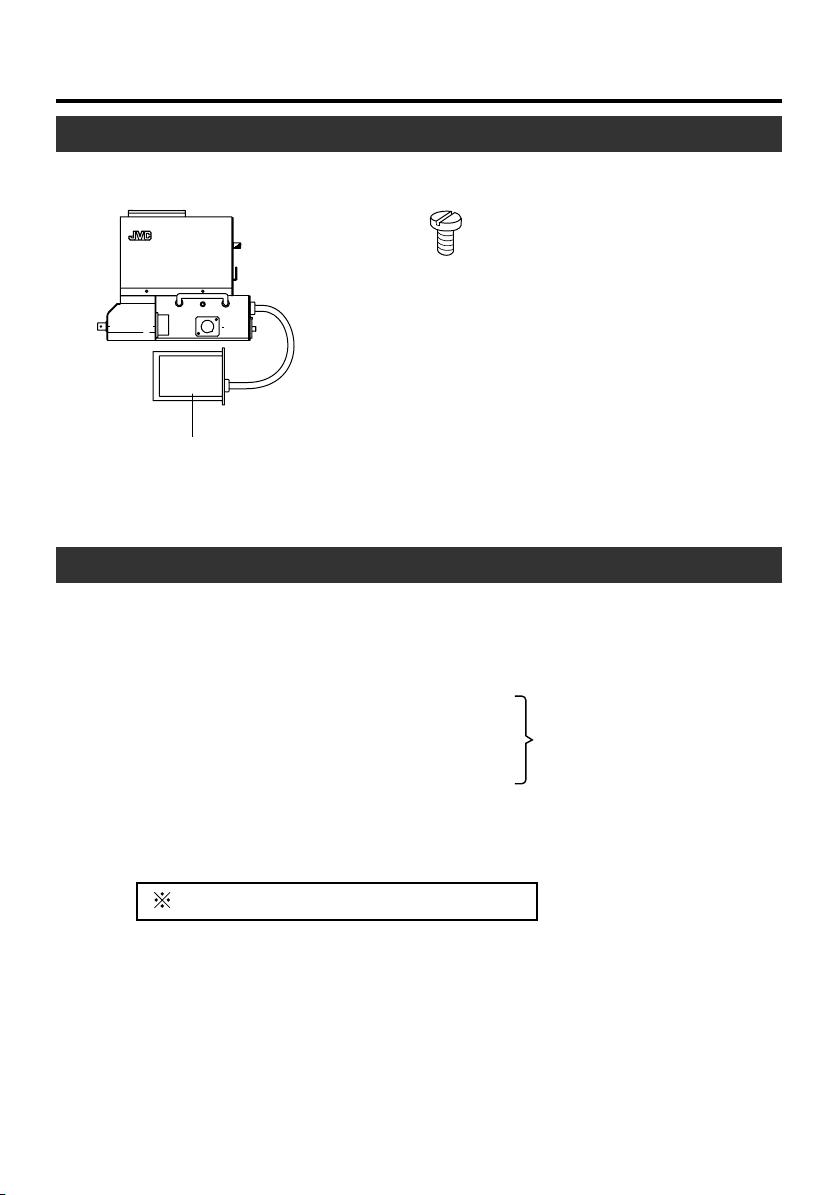
Accessories
䡵 Studio Kit main body 䡵 Screw - 1 piece: Use for securing KY-F560
camera on the Studio Kit.
BREAKER
PROMPTER
RM
OUTPUT
DC INPUT
Relay board
Related Products used in Conjunction with this Unit
● Color video camera ......................... KY-F560
● 4-inch Viewfinder ............................ VF-P400
● Remote Control Unit ....................... RM-P210
● Intercom Headset ........................... KA-310U
● 26 Pin Camera Cable ..................... VC-P110 (5 m)
● Use the undermentioned AC power supply if the Remote Control Unit RM-P210 is not in-
use.
AC Power Supply............................ AA-P250
䡵 Instructions (this booklet)
VC-P112 (20 m)
VC-P113 (50 m)
Select either one.
VC-P114 (100 m)
Please refer to page 13 ‘System’ for details.
8
Page 9
Precautions
䢇 In order to ensure that this unit could serve
you longer, avoid storing or using it at the
following places.
䡵 Extremely hot or cold places
䡵 Places with strong vibration
䡵 Dusty places
䢇 Earthing the INTERCOM G(GND) terminal
is recommended as noises may be induced
depending on the intercom headset used.
䢇 Use only the specified standard length
camera cable. Otherwise, the cable compensation may be insufficient.
䡵 High humidity places
䡵 In the vicinity of strong noise sources
䢇 Do not subject this unit to strong vibration
Caution
or impact when installing or moving it.
䢇 Do not plug in or plug out the camera ca-
ble connector when this unit has been powered on.
䢇 Use only the designated power supply. Use
either RM-P210 or AA-P250.
䢇 To reduce power consumption, turn off the
Moving this unit with the supporting tripod
attached may cause it to detach and drop
if there is sudden external impact or
vibration. This may cause injuries. Please
remove this unit from the tripod before
moving it.
power when not in-use.
䢇 When transceiver or mobile phone is used
near this unit, noises may be introduced
into the intercom speaker or the screen.
This is not a malfunction.
Regarding Gain-lock Signal and adjustment of System Phase
English
When using RM-P210 Remote Control Unit
with this system, Gain-lock signal could be
input into either KY-F560 Camera or RMP210.
However, if Gain-lock signal is applied to both
KY-F560 and RM-P210, screen images will
appear jerky.
Please carry out the System Phase
adjustment via the machine where Gain-lock
signal has been input.
In addition, the first priority will be given to
RM-LP55 when connecting it.
䡵 When Gain-lock signal is input into RM-
P210
Please adjust the phase by adjusting RMP210’s H and SC.
Use RM-LP55 to adjust the phase if it is
connected to this system.
䡵 When Gain-lock signal is input into KY-
F560
Please adjust the phase by adjusting KYF560’s H and SC.
(Adjustment should be done through KY-F560
even if RM-P210 is connected).
Use RM-LP55 to adjust the phase if it is
connected to this system.
9
Page 10
Getting Started
!
Part Names and Functions
8
9
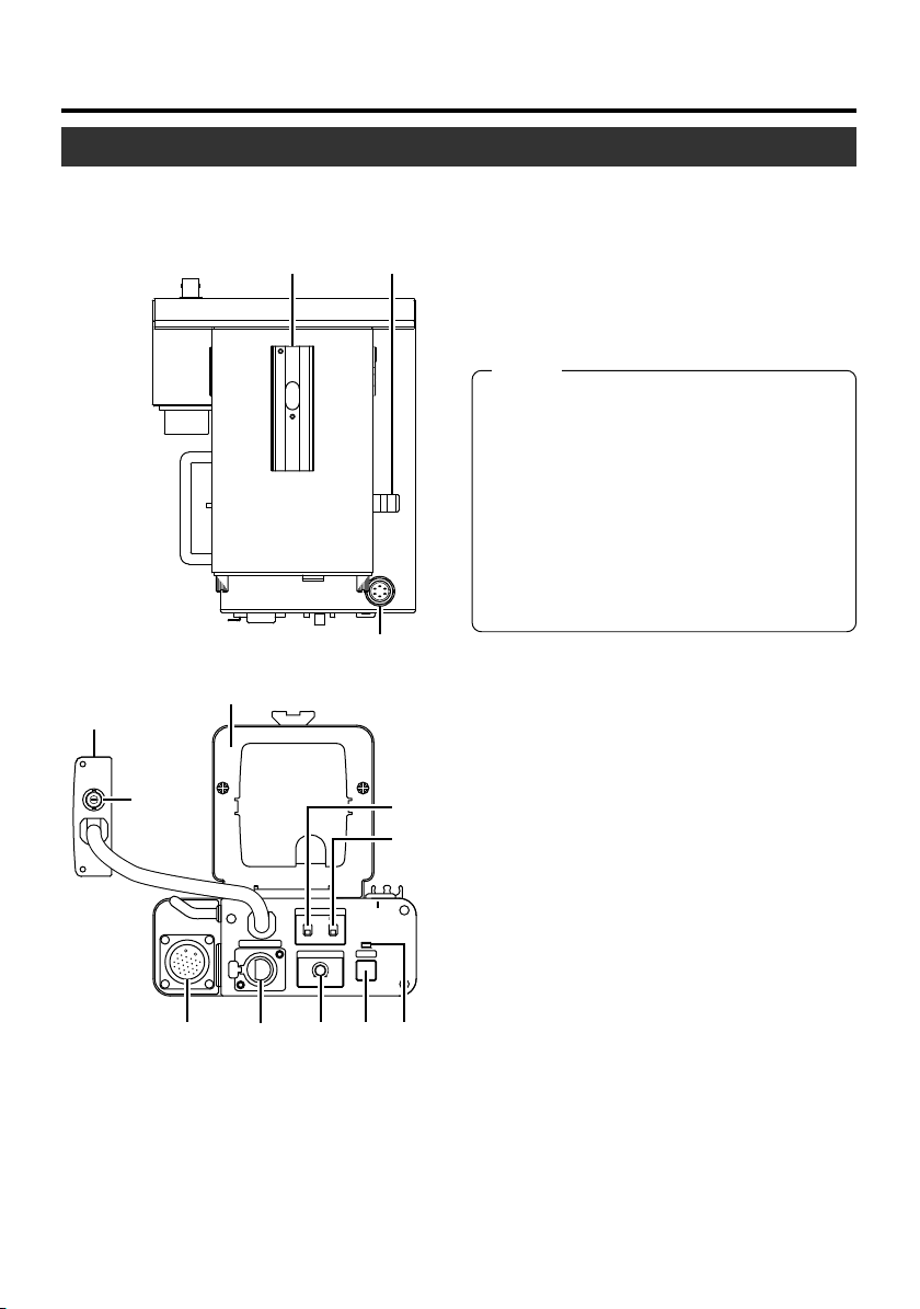
1 [RM] RM Multi-pin Connector (26 Pin)
Connect to Remote Control Unit RM-P210
#@
by using the 26 pin camera cable.
In addition, power is supplied to the this
unit and the camera via this connector
from the remote control unit.
Note
Besides Composite video signal, other
types of camera video signals which
could be output from the output terminal
of RM-P210 include RGB component,
Y/Cb/Cr component and YC separate
signal. The output signal could be selected using the “OUTPUT” item under
the “SYSTEM” menu screen on the KYF560. (☞ page 21)
2 [INTERCOM] Intercom Input Terminal
(XLR 5 Pin)
Input terminal for intercom headset. JVC
Headset KA-310U can be connected here.
10
0
INCOM MIC
ON
CARBON
OFF
INCOM LEVEL
DYNAMIC
MAXMIN
INTERCOM
PUSH
12367
4
5
VF
CALL
Volume
Use for adjusting the intercom headset receiver volume level.
4 [INCOM MIC] Intercom Mic [ON/OFF]
Switch
[ON/OFF] switch for intercom headset
microphone. Set it to [ON] if the headset
microphone is to be used.
3 [INCOM LEVEL] Intercom Receiver
Page 11
Part Names and Functions (continued)
5 [INCOM MIC] Intercom Mic [CARBON/
DYNAMIC] Switch
Use for selecting the type of intercom
headset microphone to be used.
[CARBON] : Choose this setting if car-
bon type microphone is to
be used.
[DYNAMIC] : Choose this setting if dy-
namic type microphone is
to be used.
If JVC Headset KA-310U is to be used,
choose the [CARBON] setting.
6 [CALL] Call Button
Press this button to send call signal to the
remote control unit operator if intercom
headset is not in-use.
When this button is pressed and held
down, call signal is being sent to the remote control unit and its [TALLY] button
indicator will blink. Once the [CALL] button is released, call signal will not be sent
and the [TALLY] button indicator of the remote control unit will go off.
7 [CALL] Indicator
If the remote control unit is connected, it
will light up during the duration when
[CALL] button is being pressed and held
down. The indicator will go off once the
[CALL] button is released.
6
9 Relay Board
This board is meant for connecting to KYF560 camera. This is to be inserted into
the slot at the rear of KY-F560.
0 [SDI OUT] SDI Output Terminal...Only
for KA-F5603U
Camera video is output in the form of SDI
signal.
Caution
To avoid causing malfunction, please do
not touch this terminal except when connecting cable to it.
! [VF] Viewfinder Terminal (6 Pin)
Use for connecting cable from the Viewfinder.
@ Viewfinder Holder
Use for mounting the VF-P400 4-inch
Viewfinder.
# Lens Cable Clamp
This clamp is meant for securing the lens
cable.
English
8 Camera Mounting Frame
Remove this frame for the mounting of KYF560 camera.
11
Page 12

Getting Started
Part Names and Functions (continued)
BREAKER
$
&
$ [PROMPTER OUTPUT] Prompter
Output Terminal (BNC)
Signal (prompter video signal) inputted
into the [AUX] input terminal of the remote
control unit will be outputted from this terminal via the RM multi-pin connector.
Composite signal will be outputted. Video
monitor will be connected here.
% [DC INPUT] DC Power Input Terminal
(XLR 4 Pin)
Apply DC power to this terminal if Remote
Control Unit RM-P210 is not going to be
connected. For DC power supply, use AAP250.
PROMPTER
OUTPUT
RM
DC INPUT
%^
^ [BREAKER] Breaker Switch
Breaker switch will trip and cut off the
power if the power consumed is higher
than the rated capacity. If the breaker
switch trips, confirm that there are no abnormalities and that the power consumption does not exceed the rated wattage. If
no abnormalities are detected, press the
breaker switch before turning the power
ON again to put this unit in the operating
status. If this unit still does not function
properly, consult your JVC-authorized
dealer.
& Screw Holes for Mounting Tripod
12
Page 13
Installation
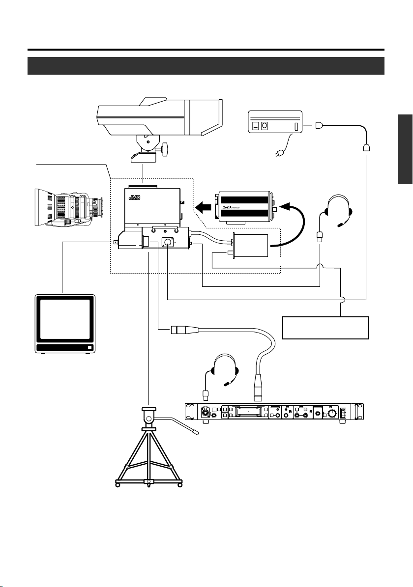
System
Studio kit/Studio SDI kit
KA-F5602U/KA-F5603U
Lens
Viewfinder VF-P400
AC power adapter AA-P250
Color video camera
KY-F560
VC-710 (5 m)
4P
4P
English
Headset KA-310U
[PROM
OUTPUT]
connector
Monitor
MACRO
PROMPTER
OUTPUT
PTER
Tripod
TP-P300
Dolly TP-P205
BREAKER
RM
DC INPUT
[DC INPUT] connector
RM multi-pin connector
Headset
KA-310U
COLOR VIDEO CAMERA KY-F560
SDI output (only KA-F5603U)
[INTERCOM] connector
26Pin camera cable
VC-P110 (5 m)
VC-P112 (20 m)
VC-P113 (50 m)
VC-P114 (100 m)
CALLTALLY
FULL AUTO F1
BARS
F2
INTERCOM
LEVEL
MENU/SHUTTER GAIN
F3
SHUTTER
SHUTTER
VARIABLE
PUSH-ON
PUSH-ON
MENU
F4
GAIN
DOWN UP
DOWN UP
Remote control unit RM-P210
SDI input
SDI compatible
video equipment
REMOTE CONTROL UNIT RM-P210
STEP
HIGH
MID
LOW
WHITE MASTER BLACK
PAINT AUTO
IRIS
W.BAL
B
A
AUTO
BR
MANU
PRESET
CLOSE OPEN
POWER
I
O
● Please refer to KY-F560 instruction manual for details on the lens and lens remote control.
● The 26 Pin camera cable used should be less than 100 m.
● Power is supplied via the 26 Pin camera cable by the Remote Control Unit RM-P210 if it is
in-use. If the Remote Control Unit RM-P210 is not in-use, please use AC power adapter
AA-P250.
13
Page 14
Installation
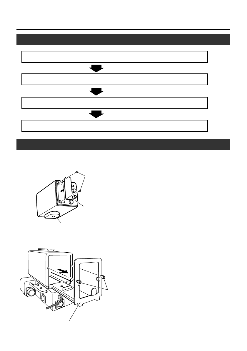
Installation Procedures
1. Mounting KY-F560 Camera on this Unit.
2. Mounting the Lens onto the Camera.
3. Mounting this Unit onto the Tripod.
4. Mounting VF-P400 4-inch Viewfinder on this Unit.
Mounting KY-F560 Camera on this Unit
1.
1.
Screw Å
Slot cover
Preparations to be done on KY-F560 camera.
● If the lens is attached to KY-F560 cam-
era, remove and place it aside.
● Attached the camera mounting bracket
at the bottom of the camera.
● Remove 2 screws Å from the rear of
the camera and take out the slot cover.
14
2.
Camera mounting bracket
Camera mounting frame
Screw ı
2.
Loosen 2 screws ı of this unit and pull
out the camera mounting frame.
Page 15
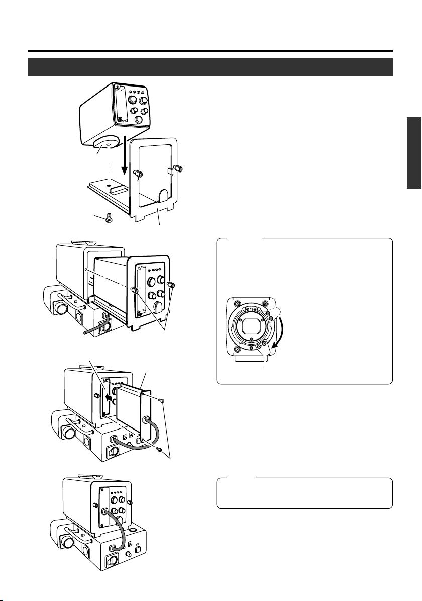
Mounting KY-F560 Camera on this Unit (continued)
3.
Mounting bracket
Screw Ç
4.
5.
Slot
Camera mounting frame
Screw ı
Relay board
3.
Place the camera on top of the camera
mounting frame and use the screw Ç pro-
vided to secure the camera to the base of
the frame.
Use the camera mounting bracket screw
hole to secure the camera.
4.
After the camera mounting frame is inserted into this unit, secure it by screwing
back the 2 screws ı which were taken
out earlier in above-mentioned step
Notes
● Please remove the camera lens mount
cap before hand.
● Before inserting the camera mounting
frame into this unit, turn the lens secure
lever located in front of
the camera clockwise to
move it to a lower position. If the lever remains
at the upper position, it
may hit this unit when the
Lever
frame is being inserted.
2.
English
.
Screw Ç
5.
Insert this unit’s relay board into the slot
at the rear of the camera and secure it by
screwing back the 2 screws Å which were
taken out earlier in above-mentioned
step
1.
.
Note
Ensure that the relay board is inserted
all the way in.
15
Page 16

Installation
Mounting the Lens onto the Camera
Please refer to KY-F560 instruction manual on mounting the lens.
● When using the under-mentioned types of lens, lens cable ECE-R22 which is sold sepa-
rately must be used. (Please consult your local JVC authorized service agent for details of
the cable to be used.)
S17 x 6.6 BRM(FUJINON)
YH16 x 7K12U(CANON)
● Use the cable clamp to secure the lens cable to this unit.
Cable clamp
ECE-R22
Lens cable
Lens cable
Mounting this Unit onto the Tripod
Mount and fix this unit onto the tripod using the mulitple screw holes provided beneath it. Use
the appropriate screw holes for mounting this unit such that it could be balanced properly on
top of the tripod.
Screw holes
16
Page 17

Mounting VF-P400 4-inch Viewfinder on this Unit
VF-P400 4-inch
Viewfinder
Lock lever
Viewfinder holder
Viewfinder Cable
3.
1.
2.
4.
Viewfinder terminal
1.
Loosen the viewfinder lock lever by turning it anti-clockwise.
2.
Slide the viewfinder forward along the viewfinder holder guide on top of this unit.
3.
Turn the viewfinder lock lever clockwise to lock it.
4.
Plug the viewfinder cable connector into this unit’s viewfinder terminal.
English
Note
When “ASPECT RATIO” item under the “SYSTEM” menu screen of KY-F560 is set to
“16:9”, images will appear vertically elongated in the View Finder VF-P400.
17
Page 18

F.f
ft
m
30
1035
15
10
7
2
1.5
5
4
1.2
5.5 10
C16
11
8
MACRO
Connecting RM-P210
Connecting to Remote Control Unit RM-P210
26 Pin
POWER
I
O
camera
cable
RM Multi-pin
connector
INTERCOM
PUSH
[INTERCOM] terminal
Headset
KA-310U
CALLTALLY
FULL AUTO F1
BARS
INTERCOM
LEVEL
MENU/SHUTTER GAIN
PAINT AUTO
F3
SHUTTER
F2
GAIN
STEP
W.BAL
HIGH
B
VARIABLE
SHUTTER
MID
A
PUSH-ON
F4
MENU
DOWN UP
DOWN UP
AUTO
PUSH-ON
BR
MANU
PRESET
LOW
CLOSE OPEN
REMOTE CONTROL UNIT RM-P210
IRIS
WHITE MASTER BLACK
Remote control unit RM-P210
AW
BARS
MENU
SET
REMOTE
LENS
VIDEO OUT
GENLOCK IN
DC IN
POWER
SEE INST
INCOM MIC
VF
ON
CARBON
OFF
DYNAMIC
CALL
INCOM LEVEL
MAXMIN
Headset
KA-310U
Monitor
26 Pin camera cable
VC-P110 (5 m)
VC-P112 (20 m)
PROMPTER
OUTPUT
BREAKER
RM
VC-P113 (50 m)
VC-P114 (100 m)
[PROMPTER OUTPUT] terminal
Connection
Switch off RM-P210 power supply before attempting the connection.
● Connect this unit’s RM multi-pin connector and RM-P210 using the 26 Pin camera cable.
Length of the camera cable should not be longer than 100 m.
● If intercom headset is to be used, plug the Headset KA-310U into the [INTERCOM] termi-
nal.
● Prompter video (RM-P210 [AUX VIDEO INPUT] terminal’s input signal) from RM-P210
could be verified by connecting this unit’s [PROMPTER OUTPUT] terminal located in front
of it to a monitor using BNC cable.
Note
Power for this unit and the camera is supplied by RM-P210 via the 26 Pin camera cable.
Setting
䡵 Menu screen setting
● Composite video signal is always output at the RM multi-pin connector.In addition, another
type of video signal which could be either RGB component, Y/Cb/Cr component or YC
separate signal could be outputted. The output signal could be selected using the “OUTPUT” item under the “SYSTEM” menu screen.
● If the output signal is RGB component, option to superimpose SYNC signal onto the G
signal could be selected through the “SYNC ON G” item under the “SYSTEM” menu screen.
18
Page 19

Connecting to Remote Control Unit RM-P210 (continued)
VIDEO OUT
GENLOCK IN
DC IN
POWER
SEE INST
INCOM MIC
ON
CARBON
OFF
DYNAMIC
INTERCOM
INCOM LEVEL
PUSH
MAXMIN
Rear view of
this unit
VF
CALL
[CARBON/DYNAMIC]
switch
[INCOM MIC ON/OFF] switch
Operation
● Turn the [POWER] switch of the camera remote control unit to [ON]. After the [POWER]
switch is turned on, camera remote control unit could be operated after about 30 seconds.
Note
After the power is turned on, the camera remote control unit takes about 30 seconds to
be ready to communicate with this unit.
䡵 Switch setting
● Set the [CARBON/DYNAMIC] switch according to
the type of intercom headset microphone to be
used. (If JVC Headset KA-310U is connected,
choose the [CARBON] setting.))
● Set the [INCOM MIC ON / OFF] switch depending
on whether headset microphone will be used. If the
switch is set to [ON], then the headset microphone
could be used.
English
● When this unit’s [CALL] button is pressed and held
down, call signals will be sent to the remote control
unit operator and the [TALLY] button indicator of
the remote control unit will blink.
During this duration, the [CALL] indicator of this unit
will light up. The Viewfinder’s [TALLY] lamp will also
blink when call signals are received from the remote control unit.
INTERCOM
PUSH
[INCOM LEVEL]
volume
VIDEO OUT
GENLOCK IN
DC IN
POWER
SEE INST
INCOM MIC
ON
CARBON
OFF
DYNAMIC
CALL
INCOM LEVEL
MAXMIN
[CALL] button
VF
[CALL]
Indicator
● The headset reception volume could be adjusted
by [INCOM LEVEL] volume.
Note
● If both this unit (including the camera) and the remote control unit have the same func-
tional switches, the remote control unit switches will be accorded higher priority.
● If local Remote Control Unit (RM-LP55 or RM-LP57) is used simultaneously, the local
remote control unit will be accorded higher priority.
● When synchronization signal is added to both the camera and the camera remote con-
trol unit, pictures will be distorted. (☞ page 9 ‘Regarding Gain-lock Signal and adjustment of System Phase’)
● If external synchronization signal is present when the power is turned on, pictures may
appear jerky for a few seconds. This is not a malfunction.
● When using the remote control unit, refer to its instruction manual for details.
19
Page 20

Connecting RM-P210
Notes to be taken when operating RM-P210
When using RM-P210 menu to carry out the setting of KY-F560, some items of RM-P210
menu setting may not be consistent with the operations of KY-F560.
No
4G
䡵 “PROCESS”
screen
“KNEE POINT”
(KNEE POINT setting
when AUTO KNEE is
off)
4K
5B
“GAMMA LEVEL”
(GAMMA CURVE
Correction)
䡵 “OPERATION”
screen
“V. GAIN STEP”
(VARIABLE GAIN
STEP SETTING)
RM-P210 Menu
Item
Variable Value
10
~~
NORMAL
–10
10
~~
NORMAL
–10
0.1 dB
1.0 dB
Operation of KY-F560
KNEE point may vary as follows:
NORMAL : 100 % (Maximum level)
~
–10 : 80 % (Minimum level)
Level will change by 5 % with every
2-step adjustment on the minus side.
Setting the plus side (1 to 10) will not
change the KNEE point.
Level will change (switch to next level)
with every 2-step adjustment.
(–5 ~NORMAL ~5)
With 0.1 dB setting, turning of RMP210 [VARIABLE GAIN] knob will
cause the gain level to change at 0.2
dB step.
With 1.0 dB setting, gain level will
change at 1.0 dB step.
~
20
Page 21

Menu Screen
When KY-F560 camera is mounted on this unit, new menu screens and menu items are
added to the original KY-F560 menu screen.
The additional new menu screens and menu items will be explained here.
Please refer to KY-F560 instruction manual for details on menu screen setting.
“SYSTEM” Menu Screen
The following additional items are added to the “SYSTEM” menu screen.
The settings in bold are factory settings.
Item
“OUTPUT”
“SYNC ON G”
From RM multi-pin connector, besides the composite signal, another type of output video signal could be outputted. The additional output signal is selected here.
“Y/Cb/Cr” : Y/Cb/Cr component signal will be outputted.
“RGB” : RGB component signal will be outputted.
Option to superimpose SYNC signal onto the G signal
could be selected under the item “SYNC ON G”.
“Y/C” : YC separate signal will be outputted.
Option to superimpose SYNC signal onto the G signal of the RGB
component signal is selected here.
This item could only be set when “RGB” has been selected under
the “OUTPUT” item.
“ON” : SYNC signal will be superimposed.
“OFF” : SYNC signal will not be superimposed.
English
Function/Variables
21
Page 22

Menu Screen
“DISPLAY” Menu Screen
Additional new “DISPLAY” menu screens are added.
The settings in bold are factory settings.
Item
“CHARACTER”
“F NO.”
“SAFETY ZONE”
“CENTER MARK”
Function/Variables
To select whether characters will be displayed in the viewfinder.
“OFF” : Characters will not be displayed.
“ON” : Characters will be displayed.
Whether to display characters could be selected
individually at the next item.
Even if this item is set to “ON”, no character will be displayed if
the individual character item is set to “OFF”.
To select whether to display the lens iris F value on the viewfinder.
“OFF” : Will not be displayed.
“ON” : Will be displayed.
To select whether to display safety zone and its style on the viewfinder.
“OFF” : Will not be displayed.
“NORMAL” : Safety zone with aspect ratio of 4:3 will be displayed.
“16:9” : Safety zone with aspect ratio of 16:9 will be displayed.
To select whether to display the centre mark when the display of
safety zone has been selected.
“OFF” : Will not be displayed.
“ON” : Will be displayed.
“TALLY”
22
To select whether viewfinder [TALLY] lamp will be turned on when
signal is applied to the [TALLY] terminal located at the rear of the
Remote Control Unit RM-P210.
“OFF” : Lamp will not be turned on.
“ON” : Lamp will be turned on.
Page 23

Others
Specifications
RM Multi-pin connector : Composite video signal output
(Either Y/Cb/Cr, RGB or YC separate output signal could be
selected)
PROMPTER output : PROMPTER video signal output (composite signal)
SDI output : Serial digital video signal (SMPTE259M-compliant)
0.8 V(p-p), 75 ¸ Unbalanced (only for KY-F5603U)
Operating temperature range : –5 °C to 40 °C (Humidity below 80 %)
Allowable storage temperature : –20 °C to 60 °C
Power supply voltage : DC12 V
Power consumption : KA-F5602U Max. 17 W (KY-F560, VF-P400, lens in-use)
KA-F5603U Max. 18 W (KY-F560, VF-P400, lens in-use)
Dimensions : (W) 156 mm x (H) 180.3 mm x (D) 185.1 mm (Exclude
protruded part.)
Mass : Approx. 1.8 kg
Accessories : Screw .......................................... x 1
Instructions .......................................... x 1
Dimensions (Unit: mm)
English
146.6
INCOM MIC
VF
ON
CARBON
OFF
DYNAMIC
INTERCOM
CALL
INCOM LEVEL
PUSH
MAXMIN
16.5
160
180.3
57.5
185.1
95
25
156
204.3
Specifications and appearance of this unit are subject to change for further improvement
without prior notice.
23
Page 24

MEMO
............................................................................................
............................................................................................
............................................................................................
............................................................................................
............................................................................................
............................................................................................
............................................................................................
............................................................................................
............................................................................................
............................................................................................
............................................................................................
............................................................................................
............................................................................................
............................................................................................
............................................................................................
............................................................................................
............................................................................................
............................................................................................
............................................................................................
............................................................................................
............................................................................................
............................................................................................
............................................................................................
............................................................................................
24
Page 25

スタジオキット
F.f
ft
m
30
1035
15
10
7
2
1.5
5
4
1.2
5.5 10
C16
11
8
MACRO
スタジオSDIキット
型
名
KA-F5602U
KA-F5603U
取扱説明書
Japanese
PROMPTER
OUTPUT
お買い上げありがとうございます。
●ご使用の前にこの「取扱説明書」と「安全上のご注意」
を良くお読みのうえ、正しくお使いください。
特に、「安全上のご注意」は必ずお読みいただき安全
にお使いください。お読みになったあとは、保証書と
一緒に大切に保管し、必要なときにお読みください。
●製造番号は品質管理上、重要なものです。お買いあげ
の際は本機に製造番号が正しく記載されているか、ま
たその製造番号と保証書に記載されている製造番号が
一致しているかを、お確かめください。
BREAKER
RM
DC INPUT
イラストは、別売のレンズ・
ビューファインダーを取り付
けた例です。
私たちは環境・資源をたいせつにしています。
この取扱説明書はエコマーク認定の再生紙
(古紙100%)を使用しています。
Page 26

このたびは
スタジオキット KA-F5602U/KA-F5603U を
お買い上げいただきありがとうございます。
この商品は、当社カラービデオカメラKY-F560をスタジオカメラとして使用するためのキッ
トです。
SDI(SerialDigitalInterface)出力端子の有無により型名が異なります。
型名 SDI出力端子
KA-F5602U なし
KA-F5603U あり
主な特長
● アナログ26Pカメラコネクター装備
別売のリモートコントロールユニットRM-P210に接続し、最大100mまでの範囲で本機
をコントロールできます。この場合、カメラへの電源はリモートコントロールユニットから
供給されますので、カメラ用として別電源を用意する必要はありません。
● 多系統な出力
26Pカメラコネクターからはコンポジット信号の他、RGBコンポーネント、Y/Cb/Crコン
ポーネントまたはYCセパレート信号のいずれかを出力します。(メニュースイッチにて選
択します。)
● 4型ビューファインダーVF-P400装着可能
● インカム端子装備
ヘッドセットを使用することにより、リモートコント−ロールユニットのオペレーターと
のコミニュケーションが可能となります。
● プロンプタ−出力端子装備
リモートコントロールユニットからのプロンプタービデオをコンポジット信号で出力しま
す。
● 同期結合時のH位相やSC位相調整ができます。(メニュー画面にて)
● SDI出力端子装備(KA-F5603Uのみ)
カメラ映像をシリアルデジタルビデオ信号(SMPTE259M準拠)で出力します。
26
Page 27

目次
はじめに
付属品をご確認ください............................................................................. 28
本機を使用するための関連商品 ................................................................. 28
正しくお使いいただくためのご注意 ......................................................... 29
ゲンロック信号およびシステム位相調整について .................................. 29
各部の名称と働き ........................................................................................ 30
取付
システム ........................................................................................................ 33
取り付けの手順 ............................................................................................ 34
本機にKY-F560カメラを取り付ける ...................................................... 34
カメラにレンズを取り付ける ..................................................................... 36
本機を三脚に取り付ける ............................................................................. 36
本機に4型ビューファインダーVF-P400を取り付ける ........................ 37
RM-P210接続
Japanese
リモートコントロールユニットRM-P210を接続する .......................... 38
RM-P210操作時のご注意......................................................................... 40
メニュー画面
"SYSTEM"メニュー画面 ............................................................................ 41
"DISPLAY"メニュー画面 ........................................................................... 42
その他
保証とアフターサービス ............................................................................. 43
仕様 ............................................................................................................... 44
27
Page 28

はじめに
付属品をご確認ください
スタジオキット本体 スクリュー1本:KY-F560カメラをスタジオ
キットに固定するために使用
します。
BREAKER
PROMPTER
RM
OUTPUT
DC INPUT
取扱説明書(本書)
中継ボード
本機を使用するための関連商品
●カラービデオカメラ ........................... KY-F560
●4型ビューファインダー .................... VF-P400
●リモートコントロールユニット ......... RM-P210
●インターカム用ヘッドセット ........... KA-310U
●26Pinカメラケーブル ...................... VC-P110(5m)
VC-P112(20m)
VC-P113(50m)
VC-P114(100m)
● リモートコントロールユニットRM-P210を使用しない場合、AC電源は下記のものを使用
してください。
AC電源 ................................................ AA-P250
いずれかを
選択します。
28
※詳細は33ページの「システム」をご覧ください。
Page 29

正しくお使いいただくためのご注意
本機を長い間ご使用いただくために、次の
ような場所での使用および保管は避けてく
ださい。
極端に暑い所や寒い所
激しい振動のある所
ほこりの多い所
湿気の多い所
強いノイズの発生源の近く
設置、移動時に強い振動や衝撃を与えない
でください。
本機に電源を入れた状態で、カメラケーブル
コネクターを抜き差ししないでください。
電源は指定された電源をお使いください。
RM-P210より供給またはAA-P250
節電のため、使用しないときは電源を切っ
てください。
トランシーバーや携帯電話を本機の近くで
使用すると、インカムのスピーカーにノイ
ズが入ったり画面にノイズが出ることがあ
りますが、これは故障ではありません。
インカム使用時、接続システムによっては、
誘導ハムの影響を受けるため本機の
INTERCOMG(GND)端子を大地アースに
接続することをおすすめします。
カメラケーブルは、指定された標準の長さ
のものを使用してください。それ以外はカ
メラケーブル補償が不十分となります。
注意
本機を三脚に取り付けたまま
移動すると、本機や三脚に衝
撃・振動が加わった場合に、固
定部が外れ本機が落下し、けが
や事故の原因となることがあ
ります。移動は必ず本機を三脚
より外してから行なってくだ
さい。
Japanese
ゲンロック信号およびシステム位相調整について
RM-P210リモートコントロールユニットと
のシステムで使用した場合、ゲンロック信号
はKY-F560カメラおよびRM-P210のどち
らからでも入力できます。
ただし、KY-F560とRM-P210の両方にゲ
ンロック信号を入力すると、画面が乱れます。
システム位相調整は、ゲンロック信号が入力
された機器側で行なってください。
また、RM-LP55接続時は、RM-LP55が最優
先となります。
RM-P210にゲンロック信号を入力した
場合
RM-P210のH、SC調整で位相を調整してく
ださい。このシステムでRM-LP55を接続し
ている場合は、RM-LP55で位相を調整して
ください。
KY-F560にゲンロック信号を入力した
場合
KY-F560のH、SC調整で位相を調整してく
ださい。(RM-P210を接続していても、KYF560で調整してください。)
RM-LP55を接続している場合は、RMLP55で位相を調整してください。
29
Page 30

はじめに
!
各部の名称と働き
8
9
0
INTERCOM
PUSH
12367
INCOM MIC
ON
OFF
INCOM LEVEL
CARBON
DYNAMIC
MAXMIN
1
[RM]RMマルチピンコネクター(26ピン)
26ピンカメラケーブルを用いて、リモー
#@
トコントロールユニットRM-P210と接
続します。
また、このコネクターを介して、リモート
コントロールユニットから本機およびカ
メラに電源が供給されます。
メモ
カメラ映像信号はコンポジット信号の
他にRGBコンポーネント、Y/Cb/Crコ
ンポーネント、YCセパレート信号のい
ずれかをRM-P210の出力端子から出
力します。出力信号は、KY-F560の
"SYSTEM"メニュー画面の"OUTPUT"
項目で選択します。(☞41ページ)
2 [INTERCOM]インターカム入力端子
(XLR5ピン)
4
5
インターカム用ヘッドセットの入力端子
です。当社製ヘッドセットKA-310Uを接
続できます。
3 [INCOMLEVEL]インターカム用レシー
VF
CALL
バーボリューム
インターカム用ヘッドセットのレシー
バー音量を調節するボリュームです。
4 [INCOMMIC]インターカム用マイク
[ON/OFF]スイッチ
インターカム用ヘッドセットのマイクの
[ON/OFF]スイッチです。ヘッドセットの
マイクを使用する場合、[ON]に設定して
ください。
30
Page 31

各部の名称と働き(つづき)
5 [INCOMMIC]インターカム用マイク
[CARBON/DYNAMIC]スイッチ
インターカム用ヘッドセットのマイク型
式を選択します。
[CARBON] : カーボン型マイクの場
合、この設定にします。
[DYNAMIC] : ダイナミック型マイクの
場合、この設定にします。
※当社製ヘッドセットKA-310U接続時
には、[CARBON]に設定してください。
6 [CALL]コールボタン
インターカム用ヘッドセットを用いない
で、リモートコントロールユニットのオペ
レーターにコール信号を送るとき、このボ
タンを押します。
このボタンを押しているいる間、リモート
コントロールユニットにコール信号を送
り、リモートコントロールユニットの
[TALLY]ボタンが点滅します。ボタンか
ら指を離すと、コール信号の送信を止め、
リモートコントロールユニットの
[TALLY]ボタンが消灯します。
7 [CALL]インジケーター
リモートコントロールユニット接続時、
6[CALL]ボタンを押している間、点灯し
ます。[CALL]ボタンから指を離すと、消灯
します。
8 カメラ取り付け用フレーム
このフレームを外して、KY-F560カメラ
を取り付けます。
9 中継ボード
KY-F560カメラと接続すためのボード
です。KY-F560背面部のスロット部に取
り付けます。
0 [SDI]SDI出力端子…KA-F5603Uのみ
カメラ映像をSDI信号で出力します。
ご注意
故障を防ぐため、ケーブルを接続するとき
以外は、この端子に触れないでください。
! [VF]ビューファインダー端子(6ピン)
ビューファインダーからのケーブルを接
続します。
@ ビューファインダーホルダー
4型ビューファインダーVF-P400を取
り付けます。
# レンズケーブルクランプ
レンズケーブルを固定するためのクラン
プです。
Japanese
31
Page 32

はじめに
各部の名称と働き(つづき)
BREAKER
$
&
$ [PROMPTEROUTPUT]プロンプター
出力端子(BNC)
リモートコントロールユニットの[AUX]
入力端子に入力された信号(プロンプター
ビデオ信号)をRMマルチピンコネクター
を介して、この端子から出力します。
コンポジット信号で出力します。ビデオモ
ニタ−に接続します。
%
[DCINPUT]DC電源入力端子(XLR4ピン)
リモートコントロールユニットR M P210を接続しない場合、この端子にDC
電源を入力します。電源は、AA-P250を
使用してください。
32
PROMPTER
OUTPUT
RM
DC INPUT
%^
^ [BREAKER]ブレーカースイッチ
消費電力が容量オーバーしたとき、ブレー
カーが切れます。ブレーカーが切れた場合
は、何か異常があって定格電力を越えてい
ないかを確認した後、異常がなければブ
レーカーを押し、次に電源を再投入してく
ださい。それでも、正常動作しない場合は、
お買い上げ販売店または最寄りのビク
ターサービス窓口にご相談ください。
& 三脚取り付け用ネジ孔
Page 33

取付
システム
Studio kit / Studio SDI kit
KA-F5602U/KA-F5603U
Lens
MACRO
[PROMPTER
OUTPUT]
connector
PROMPTER
OUTPUT
Viewfinder
VF-P400
BREAKER
RM
Color video camera
KY-F560
DC INPUT
SDI output (only KA-F5603U)
[INTERCOM] connector
[DC INPUT] connector
AC power adapter
AA-P250
VC-710 (5 m)
4P
4P
Headset
KA-310U
COLOR VIDEO CAMERA KY-F560
Japanese
RM multi-pin connector
SDI input
SDI入力対応
ビデオ機器
Monitor
Headset
KA-310U
26Pin camera cable
VC-P110 (5 m)
VC-P112 (20 m)
VC-P113 (50 m)
Tripod
TP-P300
CALLTALLY
FULL AUTO F1
BARS
F2
INTERCOM
LEVEL
VC-P114 (100 m)
MENU/SHUTTER GAIN
F3
SHUTTER
F4
MENU
GAIN
REMOTE CONTROL UNIT RM-P210
POWER
WHITE MASTER BLACK
PAINT AUTO
STEP
HIGH
VARIABLE
SHUTTER
MID
PUSH-ON
PUSH-ON
LOW
DOWN UP
DOWN UP
IRIS
W.BAL
B
A
BR
PRESET
I
AUTO
MANU
O
CLOSE OPEN
Remote control unit
RM-P210
Dolly
TP-P205
● レンズおよびレンズリモコンはKY-F560取扱説明書をご覧ください。
● 26Pinカメラケーブルは、100m以内でお使いください。
● リモートコントロールユニットRM-P210を使用したとき、電源は26Pinカメラケーブル
を介してRM-P210から供給されます。リモートコントロールユニットRM-P210を使用
しない場合、電源はAA-P250ACpoweradapterを使用してください。
33
Page 34

取付
取り付けの手順
1.本機にKY-F560カメラを取り付けます。
2.カメラにレンズを取り付けます。
3.本機を三脚に取り付けます。
4.本機に4型ビューファインダー(VF-P400)を取り付けます。
本機にKY-F560カメラを取り付ける
1.
1.
スクリューÅ
スロットカバー
カメラ取付ブラケット
2.
KY-F560カメラに対する取付の準備作
業を行います。
● KY-F560カメラにレンズが付いてい
る場合は、レンズを外しておきます。
● カメラ取付ブラケットは、カメラの底面
に取り付けた状態にします。
● カメラ背面部のスクリュー
し、スロットカバーを外します。
Å 2本を外
34
カメラ取付用フレーム
2.
スクリュー
本機のスクリューı2本をゆるめ、カメラ
取付用フレームを引き出します。
ı
Page 35

本機にKY-F560カメラを取り付ける(つづき)
3.
取付ブラケット
スクリューÇ
4.
5.
スロット部
カメラ取付用フレーム
スクリュー
中継ボード
ı
3.
カメラ取付用フレームにカメラを置き、本
機に付属のスクリューÇを用いてフレー
ム底面部にカメラを固定します。
カメラ底面部の取付ブラケットのネジ孔
を用いて固定します。
4.
カメラを取り付けたフレームを本機に挿
入し、上記手順2.でゆるめたスクリュー
ı2本を用いて本機に固定します。
メモ
● カメラのレンズマウントキャップは
事前に取りはずしてください。
● カメラ取付フレームを本機に挿入す
るとき、カメラ前面部のレンズ固定用
レバーを時計方向に回
し、レバーを下側の位置
にしてください。レバー
が上側にあると、フレー
ムを挿入したとき、レ
バーが本機にぶつかり
レバー
挿入できなくなります。
Japanese
スクリューÇ
5.
本機の中継ボードをカメラ背面のスロッ
ト部に挿入し、上記手順1.で外したスク
Å2本を用いてカメラに固定しま
リュー
す。
メモ
中継ボードは奥まで確実に挿入してくだ
さい。
35
Page 36

取付
カメラにレンズを取り付ける
レンズの取付方法は、KY-F560取扱説明書をお読みください。
● 下記のズームレンズを使用する場合は、別売のレンズケーブルECE-R22が必要です。(ケー
ブルの詳細は、最寄りのビクターサービス窓口にご相談ください。)
S17x6.6BRM(FUJINON)
YH16x7K12U(CANON)
● レンズケーブルは本機のケーブルクランプに固定してください。
ケーブルクランプ
ECE-R22レンズケーブル レンズケーブル
本機を三脚に取り付ける
本機底面部のネジ孔を使って三脚に取り付けます。複数のネジ孔を備えていますので、本機の
バランスがとれる位置のネジ孔を使って三脚に取り付けてください。
ネジ孔
36
Page 37

本機に4型ビューファインダーVF-P400を取り付ける
4型ビューファインダー
VF-P400
ロックレバー
ビューファインダーホルダー
ビューファインダー
ケーブル
3.
1.
2.
4.
ビューファインダー端子
1.
ビューファインダーのロックレバーを反時計方向に回してロックレバーをゆるめます。
2.
ビューファインダーを本機上面部のビューファインダーホルダーのガイドに沿わせて、前
方にスライドさせます。
3.
ビューファインダーのロックレバーを時計方向に回して固定します。
4.
ビューファインダーケーブルのコネクターを本機のビューファインダー端子に接続しま
す。
メモ
KY-F560の"SYSTEM"メニュー画面の"ASPECTRATIO"項目を"16:9"に設定したと
き、ビューファインダーVF-P400には縦長の映像が表示されます。
Japanese
37
Page 38

F.f
ft
m
30
1035
15
10
7
2
1.5
5
4
1.2
5.5 10
C16
11
8
MACRO
RM-P210接続
リモートコントロールユニットRM-P210を接続する
ヘッドセット
ケーブル
KA-310U
26Pinカメラ
REMOTE CONTROL UNIT RM-P210
POWER
WHITE MASTER BLACK
CALLTALLY
FULL AUTO F1
BARS
INTERCOM
LEVEL
MENU/SHUTTER GAIN
F3
SHUTTER
SHUTTER
PUSH-ON
F2
F4
MENU
GAIN
DOWN UP
リモートコントロールユニット
RM-P210
IRIS
PAINT AUTO
W.BAL
STEP
HIGH
B
VARIABLE
MID
PUSH-ON
LOW
DOWN UP
I
A
AUTO
BR
MANU
PRESET
O
CLOSE OPEN
RMマルチピン
AW
BARS
MENU
SET
REMOTE
LENS
VIDEO OUT
GENLOCK IN
DC IN
POWER
SEE INST
INCOM MIC
VF
ON
CARBON
OFF
DYNAMIC
INTERCOM
CALL
INCOM LEVEL
PUSH
MAXMIN
ヘッドセット
KA-310U
コネクター
[INTERCOM]
端子
モニタ−
26Pinカメラケーブル
VC-P110(5m)
BREAKER
PROMPTER
RM
OUTPUT
[PROMPTEROUTPUT]端子
VC-P112(20m)
VC-P113(50m)
VC-P114(100m)
接続
接続はRM-P210の電源を切ってから行なってください。
● 本機のRMマルチピンコネクターとRM-P210を26Pinカメラケーブルで接続します。カ
メラケーブル長は100m以内でお使いください。
● インターカム用ヘッドセットを使用する場合は、[INTERCOM]端子にヘッドセットKA310Uを接続します。
● RM-P210からのプロンプタービデオ(RM-P210の[AUXVIDEOINPUT]端子の入力信
号)を確認する場合は、本機前面部の[PROMPTEROUTPUT]端子とモニタ−をBNCケー
ブルで接続します。
メモ
本機およびカメラへの電源は26Pinカメラケーブルを介してRM-P210から供給され
ます。
設定
メニュー画面の設定
● RMマルチピンコネクターからはコンポジット信号を常時出力します。その他RGBコンポー
ネント、Y/Cb/Crコンポーネント、YCセパレート信号のいずれかを出力します。出力信号は
"SYSTEM"メニュー画面の"OUTPUT"項目で選択します。
● RGBコンポーネント信号出力時、G信号にSYNC信号を付けるかどうかを"SYSTEM"メ
ニュー画面の"SYNCONG"項目で選択します。
38
Page 39

リモートコントロールユニットRM-P210を接続する(つづき)
VIDEO OUT
GENLOCK IN
DC IN
POWER
SEE INST
INCOM MIC
ON
OFF
INTERCOM
INCOM LEVEL
PUSH
本機背面
VF
CARBON
DYNAMIC
CALL
MAXMIN
[CARBON/DYNAMIC]
スイッチ
[INCOMMICON/OFF]スイッチ
操作
● カメラリモートコントロールユニットの[POWER]スイッチを[ON]にします。[POWER]
スイッチを[ON]にしてから、約30秒程度経過後、カメラリモートコントロールユニットの
操作が可能になります。
メモ
カメラリモートコントロールユニットは[POWER]スイッチが[ON]になった後、30秒
間、本機との通信が正常に動作するよう準備します。
スイッチの設定
● インターカム用ヘッドセットのマイクの型式に応
じて、[CARBON/DYNAMIC]選択スイッチを設定
します。(当社製のヘッドセットKA-310Uを接続
したときは、[CARBON]に設定してください。)
● インターカム用ヘッドセットのマイクを使用する
かどうかを[INCOMMICON/OFF]スイッチで設
定します。[ON]に設定するとヘッドセットのマイ
クが使用可能となります。
Japanese
● 本機の[CALL]ボタンを押している間、リモートコ
ントロールユニットのオペレーターにコール信号
を送信し、リモートコントロールユニットの
[TALLY]ボタンが点滅します。
その間、本機の[CALL]インジケーターが点灯しま
す。リモートコントロールユニットからのコール信
号を受信するとビューファインダーの[TALLY]ラ
ンプが点滅します。
INTERCOM
PUSH
[INCOMLEVEL]
ボリューム
VIDEO OUT
GENLOCK IN
DC IN
POWER
SEE INST
INCOM MIC
ON
CARBON
OFF
DYNAMIC
CALL
INCOM LEVEL
MAXMIN
[CALL]ボタン
VF
[CALL]インジ
ケーター
● ヘッドセットの受信音量は[INCOM LEVEL]ボ
リュームで調節できます。
メモ
● 本機(カメラを含む)とリモートコントロールユニットのスイッチ機能が同じ場合は、リ
モートコントロールユニットのスイッチ機能が優先されます。
● ローカルリモートコントロールユニット(RM-LP55またはRM-LP57)と同時に使用し
た場合、ローカルリモートコントロールユニットの設定が優先します。
● 同期信号をカメラとカメラリモートコントロールユニットの両方に入れると画面が乱れ
ます。(「ゲンロック信号およびシステム位相調整について」:☞29ページ)
● 外部同期信号を入力したまま、電源をONにすると、数秒間画面が上下にゆれますが故障
ではありません。
● ご使用時、リモートコントロールユニットの取扱説明書をお読みください。
39
Page 40

RM-P210接続
RM-P210操作時のご注意
RM-P210のメニュー操作でKY-F560カメラを設定するとき、一部のメニュー項目におい
て、RM-P210のメニュー設定表示とKY-F560の動作が一致しない点があります。
RM-P210メニュー
No.
4G
"PROCESS"画面
"KNEEPOINT"
(オートニーOFF時の
ニーポイント設定)
4K
"GAMMALEVEL"
(ガンマーカーブの補正)
"OPERATION"画面
5B
"V,GAINSTEP"
(バリアブルゲインのス
テップ設定)
項目
可変値
10
NORMAL
〜〜
-10
10
NORMAL
〜〜
-10
0.1dB
1.0dB
KY-F560の動作
ニーポイントは次のように変わります。
NORMAL: 100%(最大レベル)
〜
-10 : 80%(最小レベル)
マイナス側の2ステップで5%ずつレベ
ルが変わります。
プラス側(1〜10)に設定しても、ニーポ
イントは変化しません。
2ステップで1段階ずつレベルが変わり
ます。
(-5〜NORMAL〜5)
0.1dBに設定したとき、RM-P210の
[VARIABLEGAIN]つまみを回すと、レ
ベルが0.2dBステップで変わります。
1.0dBに設定したときは、1dBステッ
プで変わります。
〜
40
Page 41

メニュー画面
KY-F560カメラを本機に装着すると、KY-F560のメニュー画面に新規のメニュー項目やメ
ニュー画面が追加されます。
ここでは、新規追加のメニュー項目およびメニュー画面の内容を説明します。
メニュー画面の設定方法については、KY-F560の取扱説明書をご覧ください。
"SYSTEM"メニュー画面
"SYSTEM"メニュー画面に下記の項目が追加されます。
太字は工場出荷設定
項目
"OUTPUT"
"SYNCONG"
RMマルチピンコネクターからはコンポジットビデオ信号の他に、
もう一種類の映像信号を出力することができます。その出力信号を
選択します。
"Y/Cb/Cr" :Y/Cb/Crコンポーネント信号を出力します。
"RGB" :RGBコンポーネント信号を出力します。
"SYNCONG"項目でG信号にSYNC信号を付け
るかどうかを選択できます。
"Y/C" :YCセパレート信号を出力します。
RGBコンポーネント信号のG信号にSYNC信号を付けるかどうか
を選択します。
この項目は、"OUTPUT"項目の設定を"RGB"にしたときのみ設定
できます。
"ON" :SYNC信号を付けます。
"OFF" :SYNC信号を付けません。
機能・可変値
Japanese
41
Page 42

メニュー画面
"DISPLAY"メニュー画面
"DISPLAY" メニュー画面が新たに追加されます。
太字は工場出荷設定
項目
"CHARACTER"
"FNO."
"SAFETYZONE"
"CENTERMARK"
"TALLY"
機能・可変値
ビューファインダーにキャラクター表示するかどうかを選択しま
す。
"OFF" :キャラクターを表示しません。
"ON" :キャラクターを表示します。
次の項目でキャラクター表示の有無を個別に設
定できます。
※ この項目を"ON"に設定しても、個別のキャラクター項目の設定
を"OFF"に設定すると、そのキャラクターは表示されません。
レンズアイリスのF値をビューファインダーに表示するかどうか
を選択します。
"OFF" :表示しません。
"ON" :表示します。
ビュ−ファインダ−へのセイフティゾ−ン表示の有無および表示
スタイルを選択します。
"OFF" :表示しません。
"NORMAL" :アスペクト比4:3のセイフティゾ−ンを表示し
ます。
"16:9" :アスペクト比16:9のセイフティゾ−ンを表示
します。
セイフティゾ−ンを表示したとき、センターマークを表示するかど
うかを選択します。
"OFF" :表示しません。
"ON" :表示します。
リモートコントロールユニットRM-P210背面部の[TALLY]端子
に信号が入力されたとき、ビューファインダーの[TALLY]ランプ
を点灯させるかどうかを選択します。
"OFF" :点灯しません。
"ON" :点灯します。
42
Page 43

その他
保証とアフターサービス
保証書の記載内容ご確認と保存について
この商品には保証書を別途添付してあります。保証書はお買い上げ販売店でお渡ししますの
で、所定事項の記載および記載内容をご確認いただき、大切に保存してください。
保証期間について
保証期間はお買い上げ日より1年間です。
以後は有償修理となります。
保証書の記載内容によりお買い上げ販売店が修理いたします。
なお、修理保証以外の補償はいたしかねます。
故障その他による営業上の機会損失は致しません。
その他詳細は保証書をご覧ください。
保証期間経過後の修理について
保証期間経過後の修理については、お買い上げ販売店にご相談ください。修理によって機
能が維持できる場合は、お客様のご要望により有料にて修理いたします。
アフターサービスについてのお問い合わせ先
アフターサービスについてご不明の点は、お買い上げ販売店または別紙業務機器ビクター
サービス窓口案内をご覧の上、最寄りの業務機器ビクターサービス窓口にご相談ください。
商品廃棄について
この商品を廃棄する場合は、法令や地域の条例に従って適正に処理してください。
Japanese
修理を依頼されるときは
調子が悪いときは、この取扱説明書をもう一度ご覧になってお調べください。簡単な調整
で直ることがあります。それでも具合が悪いときは、お買い上げ販売店またはビクター
サービスにご相談ください。
• 機種名:KA-F5602U/KA-F5603U
• 故障の状態をできるだけ詳しく:
• ご購入年月日:
• ご住所、ご氏名、電話番号:
43
Page 44

その他
仕様
RMマルチピンコネクター:コンポジットビデオ信号出力
(Y/Cb/Cr、RGB、YCセパレートのいずれかの出力信号を選択可)
PROMPTER出力 :プロンプタ−ビデオ信号出力(コンポジット信号)
SDI出力 :シリアルデジタル映像信号(SMPTE259M準拠)
0.8V(p-p),75Ω不平衡(KY-F5603Uのみ)
使用温度範囲 :−5℃〜40℃(湿度80%以下)
許容保存温度範囲 :−20℃〜60℃
入力電源電圧 :DC12V
消費電力 :KA-F5602U最大17W(KY-F560,VF-P400,レンズ使用時)
KA-F5603U最大18W(KY-F560,VF-P400,レンズ使用時)
外形寸法 :
質量 :約1.8kg
付属品、添付物 :スクリュー .............................................. x1
外形寸法図(単位:mm)
(W)156mmx(H)180.3mmx(D)185.1mm(突起部含まず)
取扱説明書 .............................................. x1
146.6
INCOM MIC
VF
ON
CARBON
OFF
DYNAMIC
INTERCOM
CALL
INCOM LEVEL
PUSH
MAXMIN
16.5
160
180.3
25
57.5
185.1
204.3
本機の仕様および外観は、改善のため予告なく変更することがあります。
44
95
156
Page 45

メモ
.......................................................................................................
.......................................................................................................
.......................................................................................................
.......................................................................................................
.......................................................................................................
.......................................................................................................
.......................................................................................................
.......................................................................................................
.......................................................................................................
.......................................................................................................
.......................................................................................................
.......................................................................................................
.......................................................................................................
.......................................................................................................
.......................................................................................................
.......................................................................................................
.......................................................................................................
.......................................................................................................
.......................................................................................................
.......................................................................................................
.......................................................................................................
.......................................................................................................
.......................................................................................................
.......................................................................................................
Japanese
.......................................................................................................
45
Page 46

KA-F5602U/KA-F5603U
スタジオキット/スタジオSDIキット
フリーダ イヤル
携帯電話・PHS・FAXなどからのご利用は
電話
FAX
〒113-0033 東京都文京区本郷3丁目14-7ビクター本郷ビル
日本ビクター株式会社
〒192-8620 東京都八王子市石川町2969-2 電話(0426) 60-7245
© 2004 Victor Company of Japan, Limited
お客様ご相談センター
0120 – 2828 – 17
(03)
5684-9311
(03)
5684-9317
プロシステムカンパニー
[代表]
Page 47

KA-F5602U/KA-F5603U
STUDIO KIT/STUDIO SDI KIT
®
is a registered trademark owned by Victor Company of Japan, Limited
®
is a registered trademark in Japan, the U.S.A., the U.K. and many other countries.
© 2004 Victor Company of Japan, Limited
Printed in Japan
LWT0176-001B
 Loading...