

Page 1
SERVICE MANUAL
COMPACT COMPONENT SYSTEM
MB26120046
HX-GD7
Area suffix
US ------------------------ Singapore
UX -------------------- Saudi Arabia
UJ ---------------------- U.S.Military
UN ----------------------------- Asean
SURROUND MODE
COMPACT
DIGITAL AUDIO
HX-GD7
SOUND MODE
SUBWOOFER
DISC
COMPACT COMPONENT SYSTEM
CA-HXGD7 SP-HXGD7SP-HXGD7
DIGITAL
TABLE OF CONTENTS
1 PRECAUTION. . . . . . . . . . . . . . . . . . . . . . . . . . . . . . . . . . . . . . . . . . . . . . . . . . . . . . . . . . . . . . . . . . . . . . . . . 1-3
2 SPECIFIC SERVICE INSTRUCTIONS . . . . . . . . . . . . . . . . . . . . . . . . . . . . . . . . . . . . . . . . . . . . . . . . . . . . . . 1-6
3 DISASSEMBLY . . . . . . . . . . . . . . . . . . . . . . . . . . . . . . . . . . . . . . . . . . . . . . . . . . . . . . . . . . . . . . . . . . . . . . . 1-7
4 ADJUSTMENT . . . . . . . . . . . . . . . . . . . . . . . . . . . . . . . . . . . . . . . . . . . . . . . . . . . . . . . . . . . . . . . . . . . . . . . 1-36
5 TROUBLESHOOTING . . . . . . . . . . . . . . . . . . . . . . . . . . . . . . . . . . . . . . . . . . . . . . . . . . . . . . . . . . . . . . . . . 1-52
COPYRIGHT © 2004 Victor Company of Japan, Limited
No.MB261
2004/6
Page 2
SPECIFICATION
CA-HXGD7
Amplifier section Output Power SUBWOOFERS 100 W per channel, min. RMS, driven into 6 Ω at 63 Hz
with no more than 10% total harmonic distortion.
MAIN SPEAKERS 40 W per channel, min. RMS, driven into 6 Ω at 1 kHz
with no more than 10% total harmonic distortion.
Audio input sensitivity / impedance
(Measured at 1 kHz, with tape recording signal 300 mV)
Digital output OPTICAL DIGITAL OUTPUT -21 dBm to -15 dBm (660 nm ±30 nm)
VIDEO OUT Color system NTSC/PAL selectable
VIDEO (composite) 1 V(p-p)/75Ω
S-VIDEO Y (luminance):1 V(p-p)/75Ω
COMPONENT (interlace/ progressive) (Y):1 V(p-p)/75Ω
Speaker Terminals MAIN SPEAKERS:6 Ω - 16 Ω
Others AV COMPU LINKx2 (Ø3.5)
Tuner section FM tuning range 87.50 MHz - 108.00 MHz
AM tuning range 531 kHz - 1 710 kHz (at 9 kHz)
Disc player section Playable disc DVD Video/DVD Audio/CD/VCD/SVCD
Dynamic range 90 dB
Horizontal resolution 500 lines
Wow and flutter Immeasurable
Cassette deck section Frequency response Normal (type I) 50 Hz - 14 000 Hz
Wow and flutter 0.15% (WRMS)
General Power requirement AC 110 V / AC 127 V / AC 220 V / AC 230 V - AC 240 V
Power consumption 185 W (at operation) 25 W (on standby)
Dimensions (approx.) 205 mm × 370 mm × 432 mm (W/H/D)
Mass (approx.) 10.5 kg
SP-HXGD7
Type 3-Way 4-Speaker Bass-Reflex Type (Magnetically Shielded Type)
Speaker Systems Subwoofer 16 cm cone × 1
Woofer 12 cm cone × 2
Tweeter 5 cm cone × 1
Power handling capacity Subwoofer 100 W
Main speaker 40 W
Impedance Subwoofer 6 Ω
Main speaker 6 Ω
Frequency range Subwoofer 30 Hz - 1 000 Hz
Main speaker 67 Hz - 26 000 Hz
Sound pressure level Subwoofer 81 dB/W·m
Main speaker 86 dB/W·m
Dimensions (approx.) 227 mm × 432 mm × 376 mm (W/H/D)
Mass (approx.) 8 kg each
Design and specifications are subject to change without notice.
AUX IN:300 mV/47 kΩ
MIC 1/2:3.0 mV/50 kΩ
C (chrominance, burst):0.286 V(p-p)/75Ω
(PB/PR):0.7 V(p-p)/75Ω
SUBWOOFERS:6 Ω - 16 Ω
530 kHz - 1 710 kHz (at 10 kHz)
CD-R/CD-RW(recorded in Audio CD/ Video CD / Super Video CD/ MP3/ WMA/ JPEG format)
DVD-R/DVD-RW (recorded in video format)
(adjustable with the voltage selector), 50 Hz / 60 Hz
1-2 (No.MB261)
Page 3
SECTION 1
PRECAUTION
1.1 Safety Precautions
(1) This design of this product contains special hardware and
many circuits and components specially for safety purposes. For continued protection, no changes should be made
to the original design unless authorized in writing by the
manufacturer. Replacement parts must be identical to
those used in the original circuits. Services should be performed by qualified personnel only.
(2) Alterations of the design or circuitry of the product should
not be made. Any design alterations of the product should
not be made. Any design alterations or additions will void
the manufacturers warranty and will further relieve the
manufacture of responsibility for personal injury or property
damage resulting therefrom.
(3) Many electrical and mechanical parts in the products have
special safety-related characteristics. These characteristics are often not evident from visual inspection nor can the
protection afforded by them necessarily be obtained by using replacement components rated for higher voltage, wattage, etc. Replacement parts which have these special
safety characteristics are identified in the Parts List of Service Manual. Electrical components having such features
are identified by shading on the schematics and by ( ) on
the Parts List in the Service Manual. The use of a substitute
replacement which does not have the same safety characteristics as the recommended replacement parts shown in
the Parts List of Service Manual may create shock, fire, or
other hazards.
(4) The leads in the products are routed and dressed with ties,
clamps, tubings, barriers and the like to be separated from
live parts, high temperature parts, moving parts and/or
sharp edges for the prevention of electric shock and fire
hazard. When service is required, the original lead routing
and dress should be observed, and it should be confirmed
that they have been returned to normal, after reassembling.
(5) Leakage shock hazard testing
After reassembling the product, always perform an isolation check on the exposed metal parts of the product (antenna terminals, knobs, metal cabinet, screw heads,
headphone jack, control shafts, etc.) to be sure the product
is safe to operate without danger of electrical shock.Do not
use a line isolation transformer during this check.
• Plug the AC line cord directly into the AC outlet. Using a
"Leakage Current Tester", measure the leakage current
from each exposed metal parts of the cabinet, particularly any exposed metal part having a return path to the
chassis, to a known good earth ground. Any leakage current must not exceed 0.5mA AC (r.m.s.).
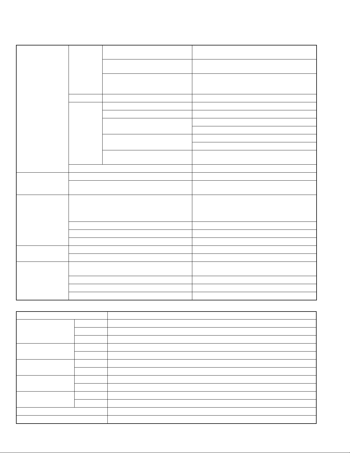
• Alternate check method
Plug the AC line cord directly into the AC outlet. Use an
AC voltmeter having, 1,000
in the following manner. Connect a 1,500
paralleled by a 0.15
exposed metal part and a known good earth ground.
Measure the AC voltage across the resistor with the AC
Ω per volt or more sensitivity
Ω 10W resistor
µF AC-type capacitor between an
voltmeter.
Move the resistor connection to each exposed metal
part, particularly any exposed metal part having a return
path to the chassis, and measure the AC voltage across
the resistor. Now, reverse the plug in the AC outlet and
repeat each measurement. Voltage measured any must
not exceed 0.75 V AC (r.m.s.). This corresponds to 0.5
mA AC (r.m.s.).
AC VOLTMETER
(Having 1000
ohms/volts,
or more sensitivity)
0.15 F AC TYPE
Place this
probe on
1500 10W
Good earth ground
1.2 Warning
(1) This equipment has been designed and manufactured to
meet international safety standards.
(2) It is the legal responsibility of the repairer to ensure that
these safety standards are maintained.
(3) Repairs must be made in accordance with the relevant
safety standards.
(4) It is essential that safety critical components are replaced
by approved parts.
(5) If mains voltage selector is provided, check setting for local
voltage.
1.3 Caution
Burrs formed during molding may be left over on some parts
of the chassis.
Therefore, pay attention to such burrs in the case of preforming repair of this system.
1.4 Critical parts for safety
In regard with component parts appearing on the silk-screen
printed side (parts side) of the PWB diagrams, the parts that are
printed over with black such as the resistor ( ), diode ( )
and ICP ( ) or identified by the " " mark nearby are critical
for safety. When replacing them, be sure to use the parts of the
same type and rating as specified by the manufacturer.
(This regulation dose not Except the J and C version)
each exposed
metal part.
(No.MB261)1-3
Page 4
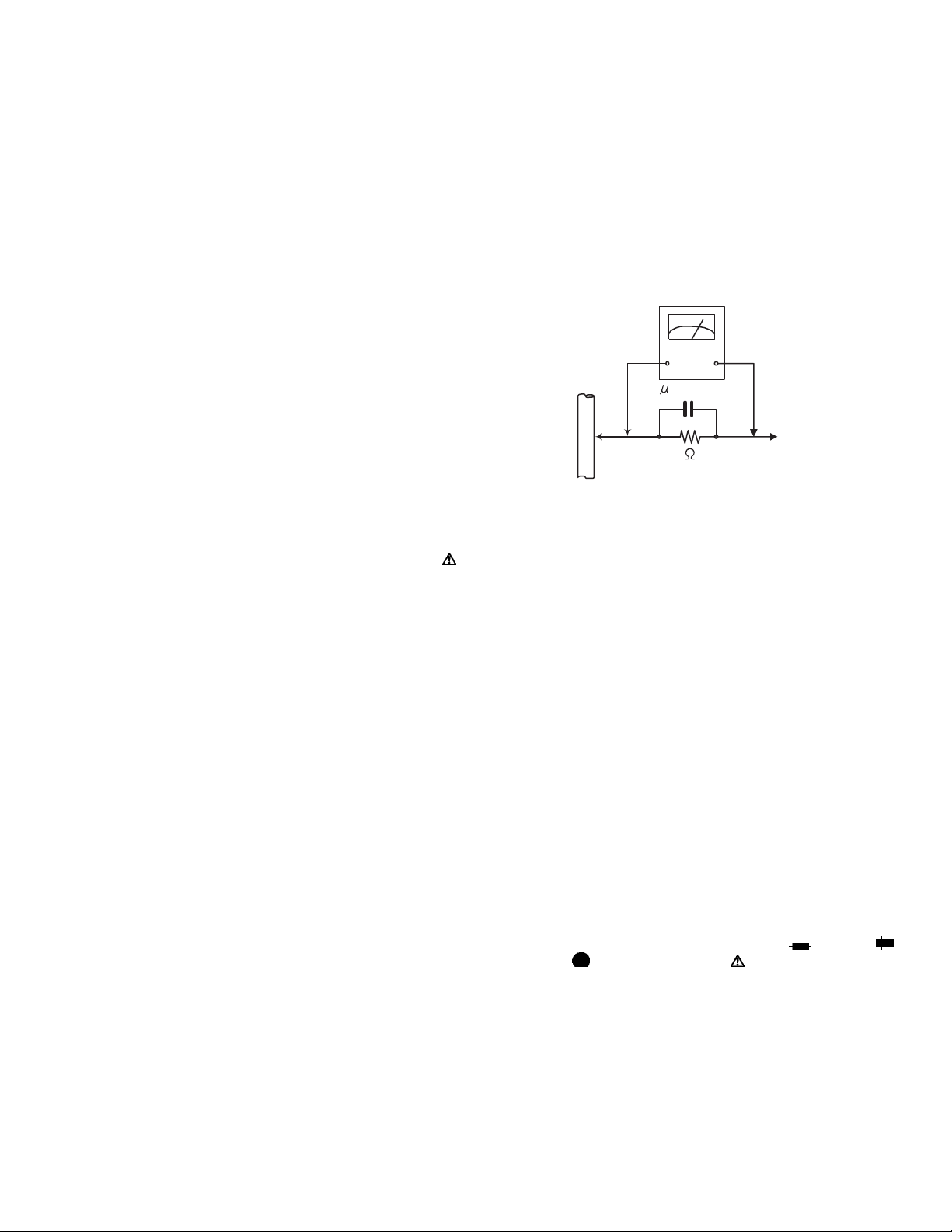
1.5 Preventing static electricity
Electrostatic discharge (ESD), which occurs when static electricity stored in the body, fabric, etc. is discharged, can destroy the laser
diode in the traverse unit (optical pickup). Take care to prevent this when performing repairs.
1.5.1 Grounding to prevent damage by static electricity
Static electricity in the work area can destroy the optical pickup (laser diode) in devices such as laser products.
Be careful to use proper grounding in the area where repairs are being performed.
(1) Ground the workbench
Ground the workbench by laying conductive material (such as a conductive sheet) or an iron plate over it before placing the
traverse unit (optical pickup) on it.
(2) Ground yourself
Use an anti-static wrist strap to release any static electricity built up in your body.
(caption)
Anti-static wrist strap
1M
Conductive material
(conductive sheet) or iron palate
(3) Handling the optical pickup
• In order to maintain quality during transport and before installation, both sides of the laser diode on the replacement optical
pickup are shorted. After replacement, return the shorted parts to their original condition.
(Refer to the text.)
• Do not use a tester to check the condition of the laser diode in the optical pickup. The tester's internal power source can easily
destroy the laser diode.
1.6 Handling the traverse unit (optical pickup)
(1) Do not subject the traverse unit (optical pickup) to strong shocks, as it is a sensitive, complex unit.
(2) Cut off the shorted part of the flexible cable using nippers, etc. after replacing the optical pickup. For specific details, refer to the
replacement procedure in the text. Remove the anti-static pin when replacing the traverse unit. Be careful not to take too long a
time when attaching it to the connector.
(3) Handle the flexible cable carefully as it may break when subjected to strong force.
(4) I t is not possible to adjust the semi-fixed resistor that adjusts the laser power. Do not turn it.
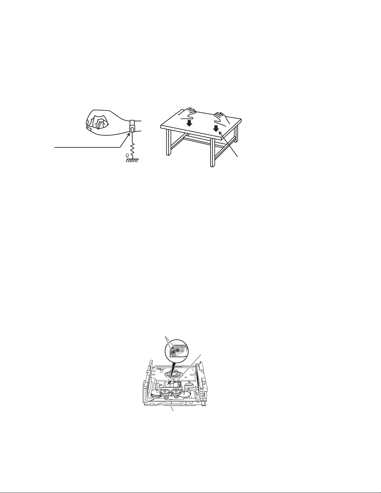
1.7 Attention when traverse unit is decomposed
*Please refer to "Disassembly method" in the text for the pickup unit.
• Apply solder to the short land sections before the flexible wire is disconnected from the connecto on the servo board. (If the flexible
wire is disconnected without applying solder, the pickup may be destroyed by static electricity.)
• In the assembly, be sure to remove solder from the short land sections after connecting the flexible wire.
Short land sections
1-4 (No.MB261)
DVD pickup
DVD changer mechanism assembly
Page 5
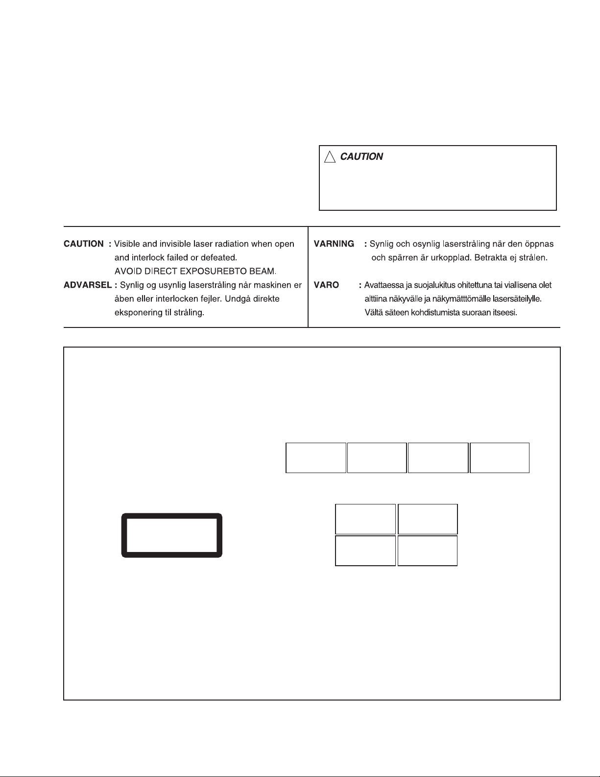
1.8 Important for laser products
!
1.CLASS 1 LASER PRODUCT
2.DANGER : Invisible laser radiation when open and inter
lock failed or defeated. Avoid direct exposure to beam.
3.CAUTION : There are no serviceable parts inside the
Laser Unit. Do not disassemble the Laser Unit. Replace
the complete Laser Unit if it malfunctions.
4.CAUTION : The CD,MD and DVD player uses invisible
laser radiation and is equipped with safety switches which
prevent emission of radiation when the drawer is open and
the safety interlocks have failed or are defeated. It is
dangerous to defeat the safety switches.
5.CAUTION : If safety switches malfunction, the laser is able
to function.
6.CAUTION : Use of controls, adjustments or performance of
procedures other than those specified here in may result in
hazardous radiation exposure.
Please use enough caution not to
see the beam directly or touch it
in case of an adjustment or operation
check.
REPRODUCTION AND POSITION OF LABELS
WARNING LABEL
CAUTION : Visible and Invisible
laser radiation when open and
interlock failed or defeated.
AVOID DIRECT EXPOSURE TO
BEAM. (e)
CLASS 1
LASER PRODUCT
ADVARSEL : Synlig og usynlig
laserstråling når maskinen er
åben eller interlocken fejeler.
Undgå direkte eksponering til
stråling. (d)
CAUTION : Visible and Invisible
laser radiation when open and
interlock failed or defeated.
AVOID DIRECT EXPOSURE TO
BEAM. (e)
VARNING : Synlig och
osynling laserstrålning när
den öppnas och spärren är
urkopplad. Betrakta ej
strålen. (s)
VARNING : Synlig och
osynling laserstrålning när
den öppnas och spärren är
urkopplad. Betrakta ej
strålen. (s)
VARO : Avattaessa ja suojalukitus
ohitettuna tai viallisena olet alttiina
näkyvälle ja näkymättömälle
lasersäteilylle. Vältä säteen
kohdistumista suoraan itseesi. (f)
ADVARSEL : Synlig og usynlig
laserstråling når maskinen er
åben eller interlocken fejeler.
Undgå direkte eksponering til
stråling. (d)
VARO : Avattaessa ja suojalukitus
ohitettuna tai viallisena olet alttiina
näkyvälle ja näkymättömälle
lasersäteilylle. Vältä säteen
kohdistumista suoraan itseesi. (f)
(No.MB261)1-5
Page 6

SECTION 2
SPECIFIC SERVICE INSTRUCTIONS
This service manual does not describe SPECIFIC SERVICE INSTRUCTIONS.
1-6 (No.MB261)
Page 7
SECTION 3
r
DISASSEMBLY
3.1 Main body section
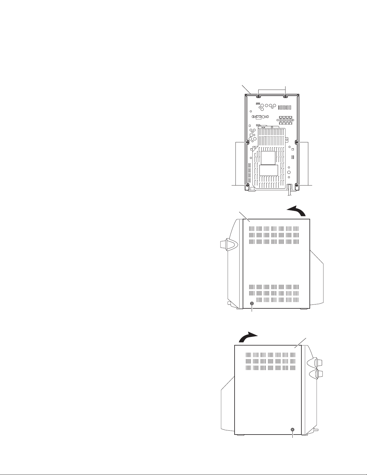
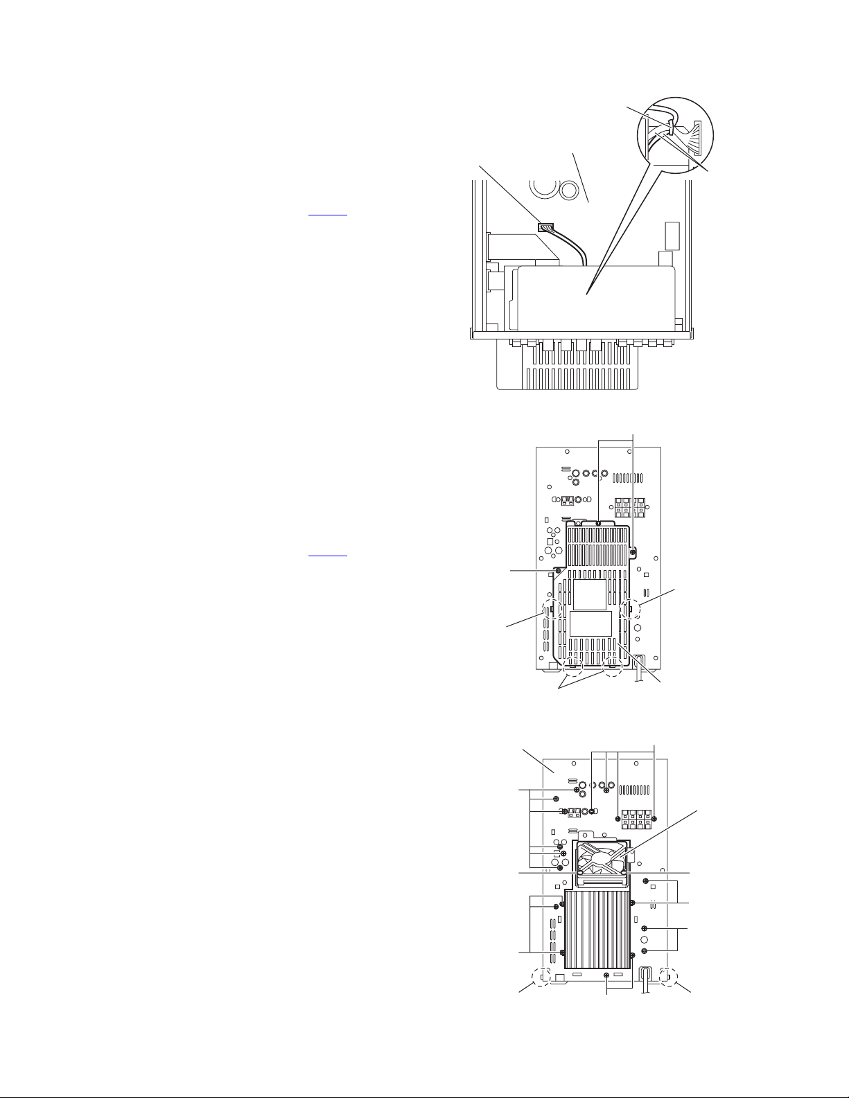
3.1.1 Removing the metal cover
(See Figs.1 to 3)
(1) From the back side of the main body, remove the six
screws A attaching the metal cover. (See Fig.1.)
(2) From the both sides of the main body, remove the two
screws B attaching the metal cover. (See Figs.2 and 3.)
(3) Remove the metal cover from the main body while lifting
the rear section of the metal cover in the direction of the arrow. (See Figs.2 and 3.)
Metal cover
A
A
Metal cover
A
Fig.1
B
Fig.2
Metal cove
B
Fig.3
(No.MB261)1-7
Page 8
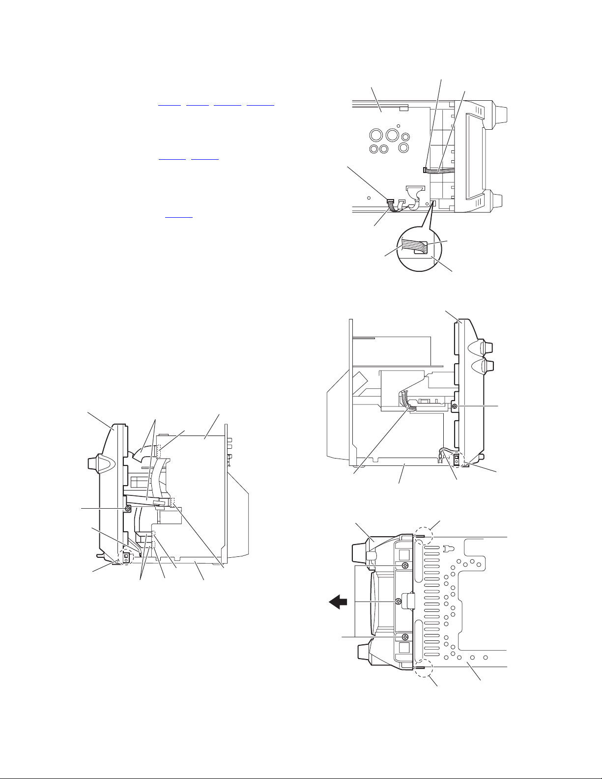
3.1.2 Removing the front panel assembly
(See Figs.4 to 7)
• Prior to performing the following procedures, remove the metal
cover.
(1) From the right side of the main body, disconnect the card
wires from the connectors (CN43
on the main board. (See Fig.4.)
(2) Disconnect the earth wire from the chassis base. (See
Fig.4.)
(3) From the top side of the main body, disconnect the parallel
wires from the connectors (CN201
board. (See Fig.5.)
Reference:
When reassembling, pass the parallel wire through the
hole a on the plastic chassis before connecting the parallel wire to the connector CN201
(See Fig.5.)
(4) From the left side of the main body, remove the tie band
bundling the wires. (See Fig.6.)
Reference:
After reassembling, bundle the wires with the new tie
band as before. (See Fig.6.)
(5) Disconnect the earth wire from the chassis base. (See
Fig.6.)
(6) From the both sides of the main body, remove the two
screws C attaching the front panel assembly. (See Figs.4
and 6.)
(7) From the bottom side of the main body, remove the three
screws D attaching the front panel assembly. (See Fig.7.)
(8) Release the joints b of the front panel assembly from the
chassis base and remove the front panel assembly in the
direction of the arrow. (See Figs.4, 6 and 7.)
Front panel assembly
Card wires
, CN44, CN802, CN803)
, CN205) on the bridge
on the bridge board.
Main board
CN802
Bridge board
CN201
Parallel wire
Parallel wire
CN205
Parallel wire
a
Plastic chassis
Fig.5
Front panel assembly
C
C
Earth wire
1-8 (No.MB261)
b
Card wires
Fig.4
CN43
CN44
CN803
Chassis base
Tie band
Chassis base
Front panel assembly
D
Fig.6
Fig.7
Earth wire
b
Chassis base
b
b
Page 9
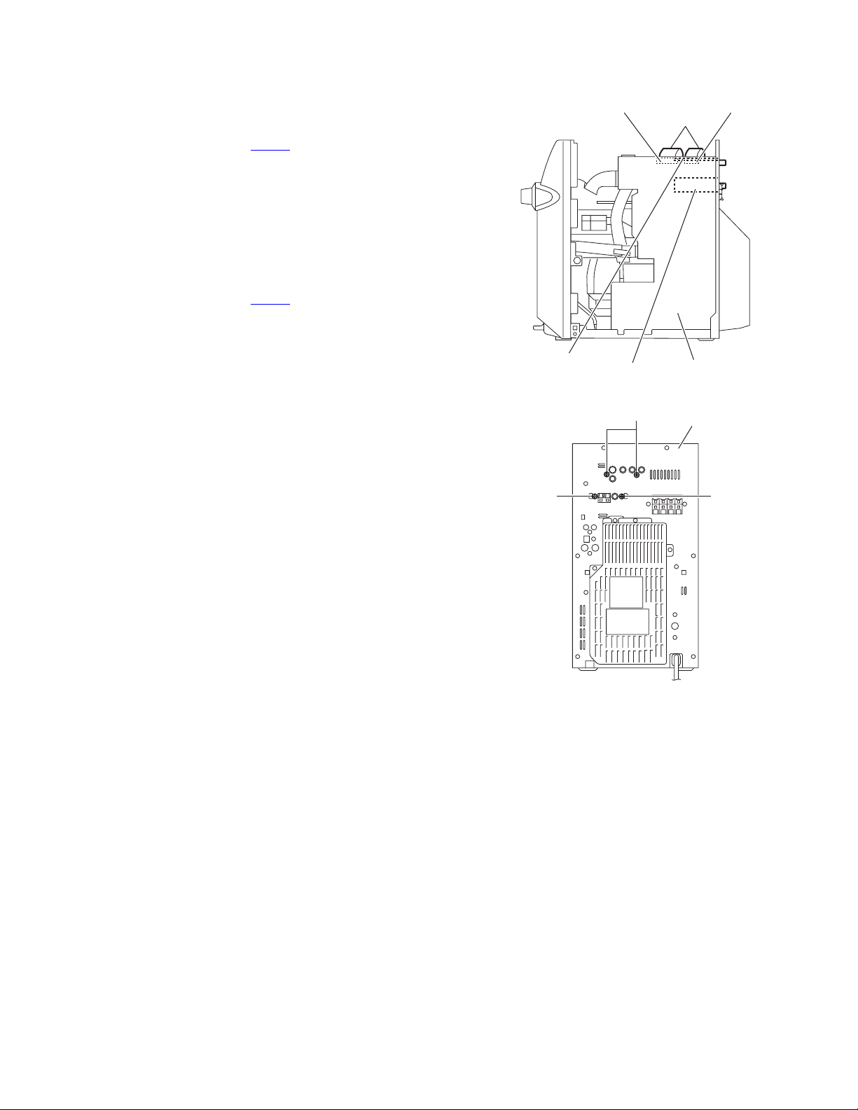
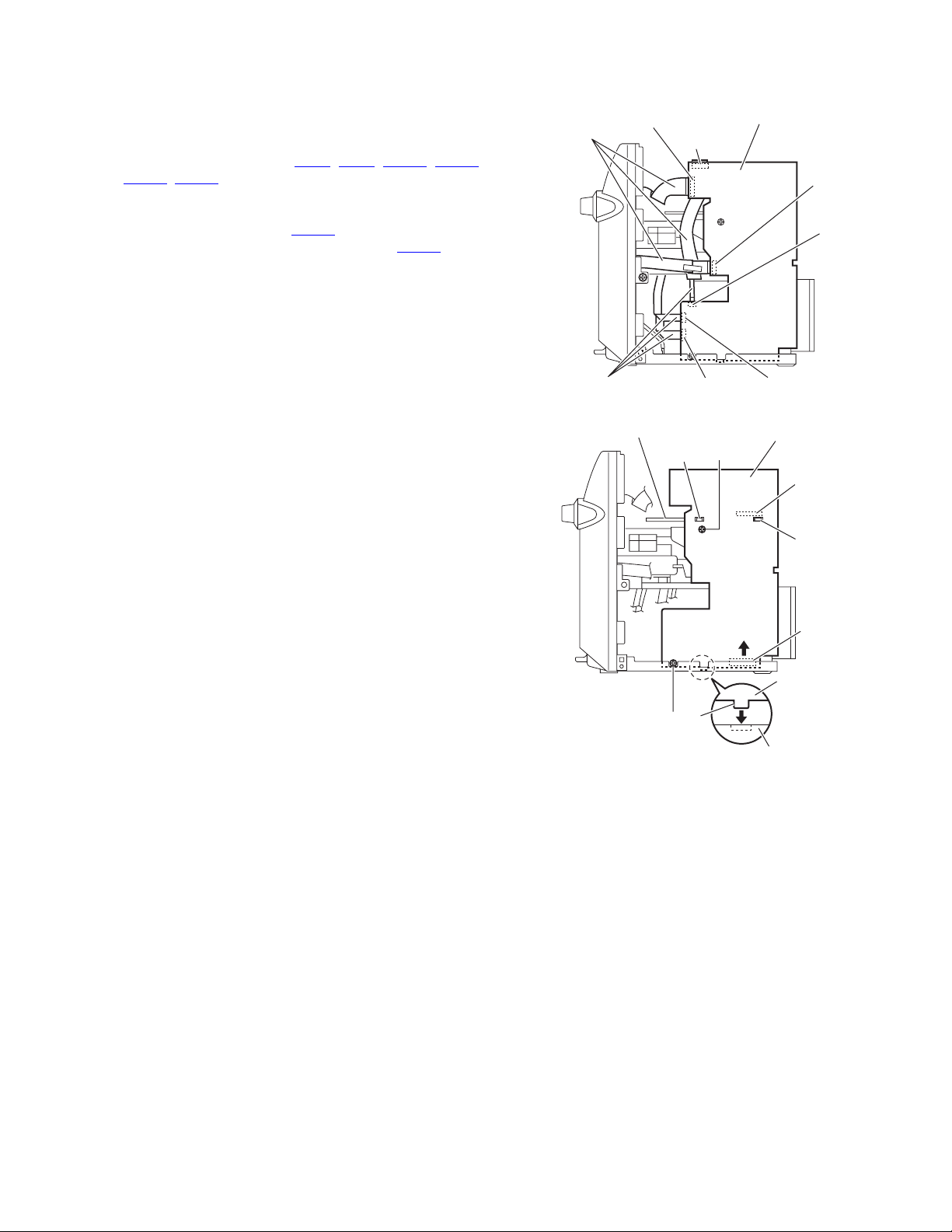
3.1.3 Removing the tuner
(See Figs.8, 9)
• Prior to performing the following procedures, remove the metal
cover.
(1) From the right side of the main body, disconnect the card
wire from the connector CN560
Fig.8.)
(2) From the back side of the main body, remove the two
screws E attaching the tuner to the rear panel. (See Fig.9.)
3.1.4 Removing the video board
(See Figs.8, 9)
• Prior to performing the following procedures, remove the metal
cover.
(1) From the right side of the main body, disconnect the card
wire from the connector CN502
Fig.8.)
(2) From the back side of the main body, remove the two
screws F attaching the video board to the rear panel. (See
Fig.9.)
on the main board. (See
on the main board. (See
Video board
CN502
Tuner
Fig.8
F
Card wires
CN560
Main board
Rear panel
E E
Fig.9
(No.MB261)1-9
Page 10
3.1.5 Removing the rear panel
r
(See Figs.10 to 12)
• Prior to performing the following procedures, remove the metal
cover.
(1) From the top side of the main body, remove the tie band
bundling the wires. (See Fig.10.)
Reference:
After reassembling, bundle the wires with the new tie
band as before. (See Fig.10.)
(2) Disconnect the wire from the connector CN202
bridge board. (See Fig.10.)
(3) From the back side of the main body, remove the two
screws G and screw H attaching the rear cover. (See
Fig.11.)
(4) Release the sections c and remove the rear cover. (See
Fig.11.)
(5) Remove the seventeen screws J and the two screws K at-
taching the rear panel. (See Fig.12.)
(6) From the both sides of the main body, release the joints d
attaching the rear panel to the chassis base and remove
the rear panel with the fan. (See Fig.12.)
3.1.6 Removing the fan
(See Figs.10 to 12)
• Prior to performing the following procedures, remove the metal
cover.
(1) From the top side of the main body, remove the tie band
bundling the wires. (See Fig.10.)
Reference:
After reassembling, bundle the wires with the new tie
band as before. (See Fig.10.)
(2) Disconnect the wire from the connector CN202
bridge board. (See Fig.10.)
(3) From the back side of the main body, remove the two
screws G and screw H attaching the rear cover. (See
Fig.11.)
(4) Remove the two screws L attaching the fan. (See Fig.12.)
(5) Take out the fan from the main body.
on the
on the
CN202
Tie band
Bridge board
Wires
Fig.10
G
H
c
c
1-10 (No.MB261)
c
Fig.11
Rear panel
J
Rear cove
J
Fan
LL
J
K
J
J
dd
Fig.12
Page 11
3.1.7 Removing the main board
(See Figs.13 and 14)
• Prior to performing the following procedures, remove the metal
cover, tuner, video board and rear panel.
(1) From the right side of the main body, disconnect the card
wires from the connectors (CN43
, CN803) on the main board. (See Fig.13.)
CN802
(2) Remove the two screws M attaching the main board. (See
Fig.14.)
(3) Disconnect the connector CN217
ward this side and disconnect the connector CN501 on the
main board in the direction of the arrow. (See Fig.14.)
Reference:
• When attaching the main board, insert the sections e of the
bridge board in the hole of the main board. (See Fig.14.)
• Insert the section f of the main board in the hole of the chassis base before attaching the screws M. (See Fig.14.)
, CN44, CN110, CN111,
on the main board to-
Card wires
CN802
Main board
CN110
CN803
CN111
Card wires
Bridge board
M
Fig.13
e
f
Fig.14
CN43CN44
Main board
M
CN217
e
CN501
Main board
Chassis base
(No.MB261)1-11
Page 12
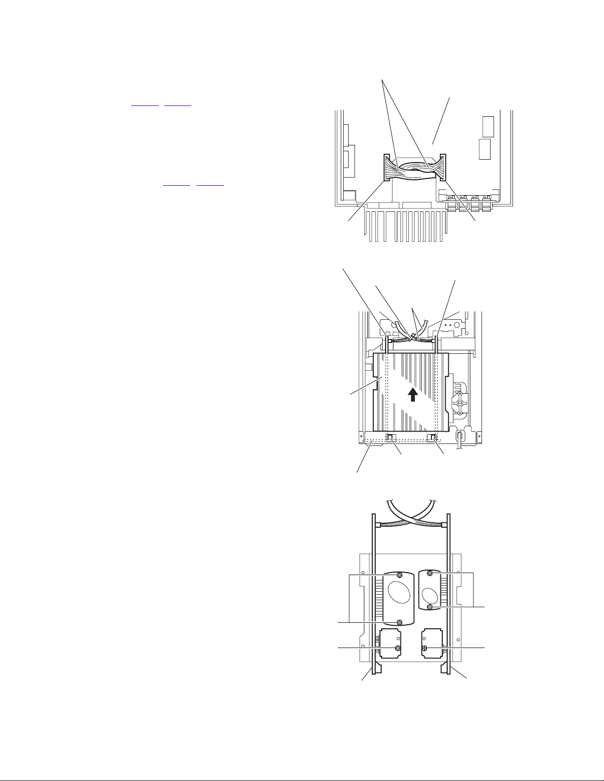
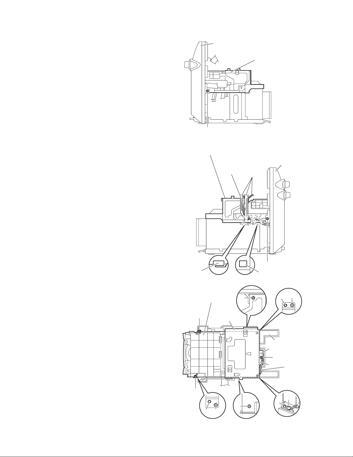
3.1.8 Removing the main amplifier board/subwoofer amplifier boards
(See Figs.15 to 17)
• Prior to performing the following procedures, remove the metal
cover, tuner, video board, rear panel and main board.
(1) From the top side of the main body, disconnect the wires
from the connector (CN206
(See Fig.15.)
(2) From the back side of the main body, remove the tie band
bundling the wires. (See Fig.16.)
Reference:
After reassembling, bundle the wires with the new tie
band as before. (See Fig.16.)
(3) Disconnect the connectors (CN600
amplifier/subwoofer amplifier boards from the connection
board in the direction of the arrow. (See Fig.16.)
(4) Remove the two screws N and screw P attaching the main
amplifier board. (See Fig.17.)
(5) Removing the two screws Q and screw R attaching the
subwoofer amplifier board. (See Fig.17.)
, CN208) on the bridge board.
, CN700) on the main
Wires
Main amplifier board
Tie band
Bridge board
CN206CN208
Fig.15
Subwoofer amplifier board
Wires
Heat sink
CN600 CN700
Connection board
Fig.16
Q
R
Subwoofer amplifier board
Fig.17
N
P
Main amplifier board
1-12 (No.MB261)
Page 13
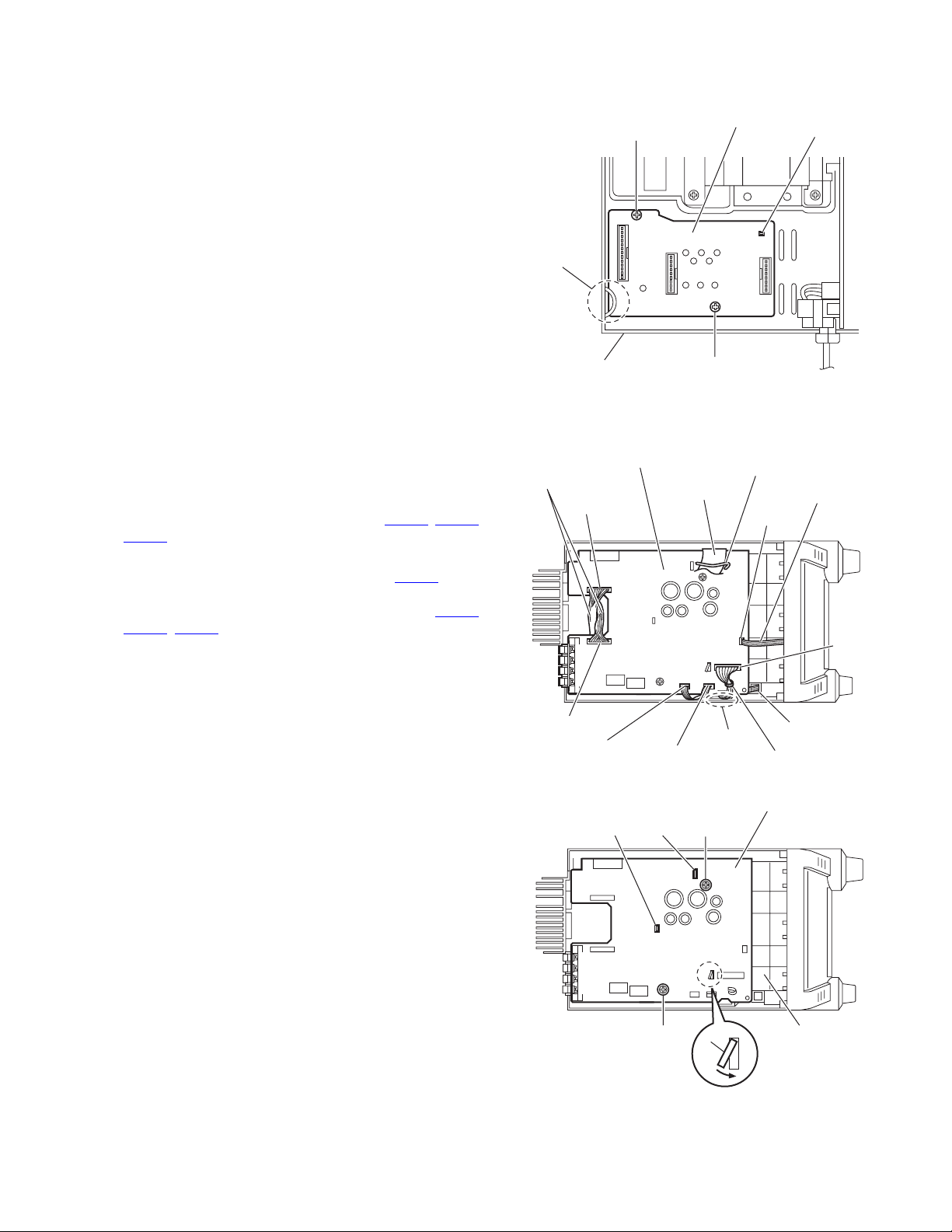
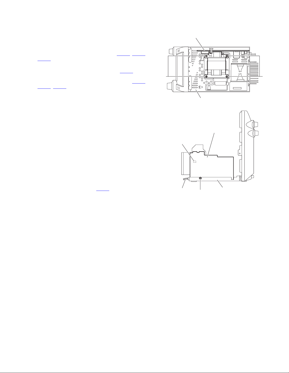
3.1.9 Removing the connection board
r
(See Fig.18.)
• Prior to performing the following procedure, remove the metal
cover, tuner, video board, rear panel, main board and main
amplifier/subwoofer amplifier boards.
(1) From the top side of the main body, remove the two screws
S attaching the connection board on the chassis base.
Reference:
When reassembling, attach the connection board to the section g and align the projection h of the chassis base to the hole
of the connection board.
S
Connection board
g
h
3.1.10 Removing the bridge board
(See Figs.19 and 20)
• Prior to performing the following procedures, remove the metal
cover, tuner, video board, rear panel and main board.
(1) From the top side of the main body, release the wire holder
bundling the wire. (See Fig.19.)
(2) Disconnect the wires from the connectors (CN206
) on the bridge board. (See Fig.19.)
CN214
Reference:
After connecting the wire to the connector CN214
wire with the wire holder. (See Fig.19.)
(3) Disconnect the parallel wires from the connectors (CN201
CN205, CN213) on the bridge board. (See Fig.19.)
(4) Release the wire holder holding the card wire. (See
Fig.19.)
(5) Remove the two screws T attaching the bridge board on
the 5DVD changer mechanism assembly. (See Fig.20.)
(6) Bend the claw i in the direction of the arrow and remove the
bridge board in an upward direction. (See Fig.20.)
Reference:
• When attaching the bridge board, align the projections (j, k)
in the hole of the bridge board. (See Fig.20.)
• When reassembling, pass the wires through the sections
(m, n) of the plastic chassis. (See Fig.19.)
, CN208,
, fix the
Chassis base
Bridge board
Wires
CN208
,
CN206
CN201
CN213
j
k
S
Fig.18
Wire holder
Card wire
m
Fig.19
Bridge board
T
Parallel wire
CN205
CN214
n
Wire holder
T
i
Fig.20
5DVD change
mechanism
assembly
(No.MB261)1-13
Page 14
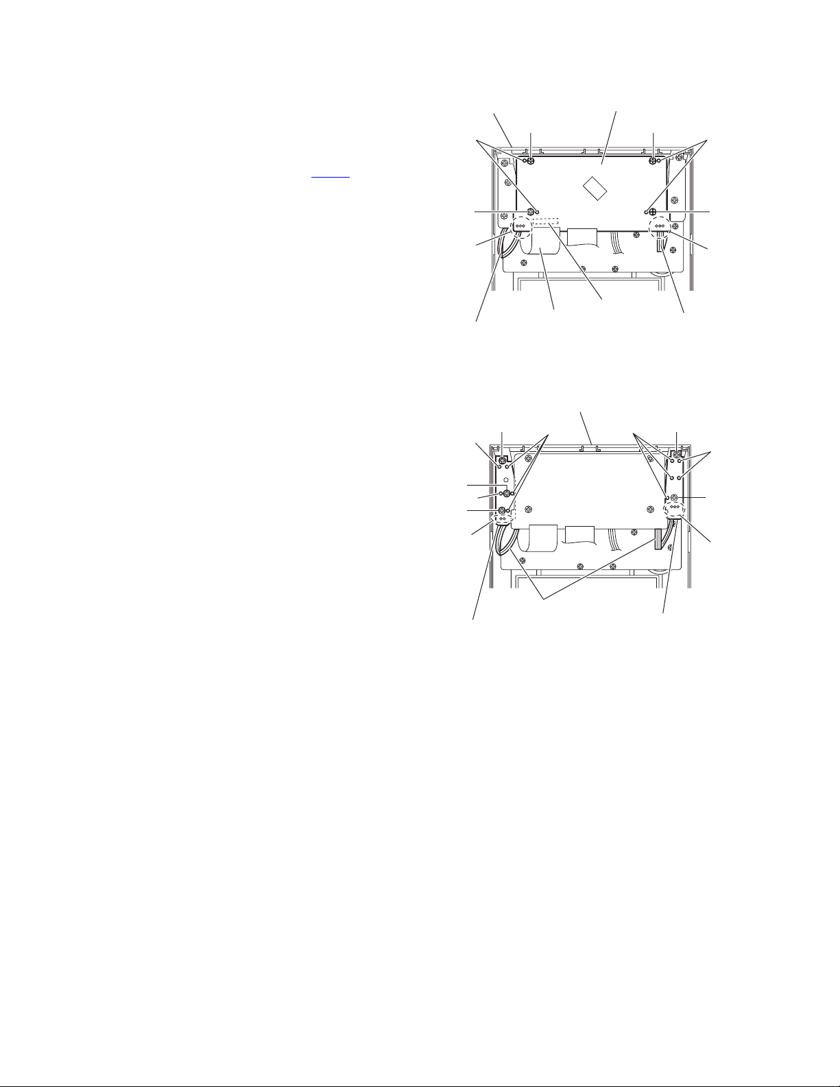
3.1.11 Removing the 5DVD changer mechanism assembly
(See Figs.21 to 23)
• Prior to performing the following procedures, remove the metal
cover, tuner, video board, rear panel, main board and bridge
board.
(1) From the both sides of the main body, remove the two
screws U attaching the 5DVD changer mechanism assembly to the front panel assembly. (See Figs.21 and 22.)
(2) From the left side of the main body, remove the tie band
bundling the wire and parallel wires. (See Fig.22.)
Reference:
After reassembling, bundle the wire and parallel wires
with the new tie band as before. (See Fig.22.)
(3) Take out the 5DVD changer mechanism assembly from the
main body.
Reference:
When attaching the 5DVD changer mechanism assembly, pass the wires through the sections (m, n) of the
plastic chassis. (See Fig.22.)
(4) From the both and top sides of the 5DVD changer mecha-
nism assembly, remove the two screws V and screw V’ at-
taching the main chassis. (See Fig.23.)
Reference:
• Align the projections s of the plastic chassis to the
holes of the main chassis before attaching the screw
V’. (See Fig.23.)
• When attaching the screw V’, attach the earth wire
with it. (See Fig.23.)
(5) Take out the main chassis.
(6) From the top side of the 5DVD changer mechanism as-
sembly, remove the three screws W and screw W’ attaching the 5DVD changer mechanism assembly on the plastic
chassis.
Reference:
• When reassembling, align the projections (p, q, r) of the
plastic chassis to the holes of the 5DVD changer mechanism
assembly before attaching the screws W and W’. (See
Fig.23.)
• When attaching the screw W’, attach the earth wire with it.
(See Fig.23.)
Front panel assembly
5DVD changer
mechanism assembly
U
Fig.21
5DVD changer mechanism assembly
Front panel assembly
Tie band
m
5DVD changer
mechanism assembly
Wires
n
Fig.22
V
U
p
W
1-14 (No.MB261)
W
W
Main chassis
r
W
V
Fig.23
Plastic chassis
s
V'
s
Earth wire
W'
q
Page 15
3.1.12 Removing the primary board
(See Figs.19, 21, 22, 24 and 25)
• Prior to performing the following procedures, remove the metal
cover, tuner, video board, rear panel and main board.
(1) From the top side of the main body, release the wire holder
bundling the wire. (See Fig.19.)
(2) Disconnect the wires from the connectors (CN206
CN214) on the bridge board. (See Fig.19.)
Reference:
After connecting the wire to the connector CN214
wire with the wire holder. (See Fig.19.)
(3) Disconnect the parallel wires from the connectors (CN201
, CN213) on the bridge board. (See Fig.19.)
CN205
(4) Release the wire holder holding the card wire. (See
Fig.19.)
(5) From the both sides of the main body, remove the two
screws U attaching the 5DVD changer mechanism assembly to the front panel assembly. (See Figs.21 and 22.)
Reference:
It is not necessary to remove the bridge board from the
5DVD changer mechanism assembly.
(6) Take out the 5DVD changer mechanism assembly with the
bridge board from the main body.
Reference:
When attaching the 5DVD changer mechanism assembly, pass the wires through the sections (m, n) of the
5DVD changer mechanism assembly. (See Fig.22.)
(7) From the top and left sides of the main body, remove the
four screws X and screw Y attaching the primary board on
the chassis base. (See Figs.24 and 25.)
(8) From the forward side of the primary board, disconnect the
power cord from the connector CN200
. (See Fig.25.)
, CN208,
, fix the
Primary board
,
X
Chassis base
Fig.24
Primary board
CN200
Chassis basePower cord
X
Y
Fig.25
(No.MB261)1-15
Page 16
3.1.13 Removing the FL board
(See Fig.26)
• Prior to performing the following procedures, remove the metal
cover and front panel assembly.
(1) From the inside of the front panel assembly, remove the
soldered sections (t, u) on the FL board to remove the parallel wires.
(2) Disconnect the card wire from the connector CN902
FL board.
(3) Remove the four screws Z attaching the FL board.
Reference:
When attaching the FL board, align the projections v of the
front panel assembly in the holes of the FL board before attaching the screws Z.
on the
Front panel assembly
v
t
Z
FL board
Z
v
ZZ
u
3.1.14 Removing the switch board
(See Fig.27)
• Prior to performing the following procedures, remove the metal
cover and front panel assembly.
(1) From the inside of the front panel assembly, remove the
three screws AA attaching the switch board.
(2) Take out the switch board and remove the soldered section
w on the switch board to remove the parallel wire.
Reference:
When attaching the switch board, align the projections x in the
holes of the switch board before attaching the screws AA.
3.1.15 Removing the standby LED board
(See Fig.27)
• Prior to performing the following procedures, remove the metal
cover and front panel assembly.
(1) From the inside of the front panel assembly, remove the
two screws AB attaching the standby LED board.
(2) Take out the standby LED board and remove the soldered
section y on the standby LED board to remove the parallel
wire.
Reference:
When attaching the standby LED board, align the projections
z in the holes of the standby LED board before attaching the
screws AB.
Parallel wire
x
AA
x
AA
w
Switch board
Card wire
Front panel assembly
AA
Parallel wires
x
CN902
Fig.26
z
Standby LED board
Fig.27
Parallel wire
AB
z
AB
y
1-16 (No.MB261)
Page 17
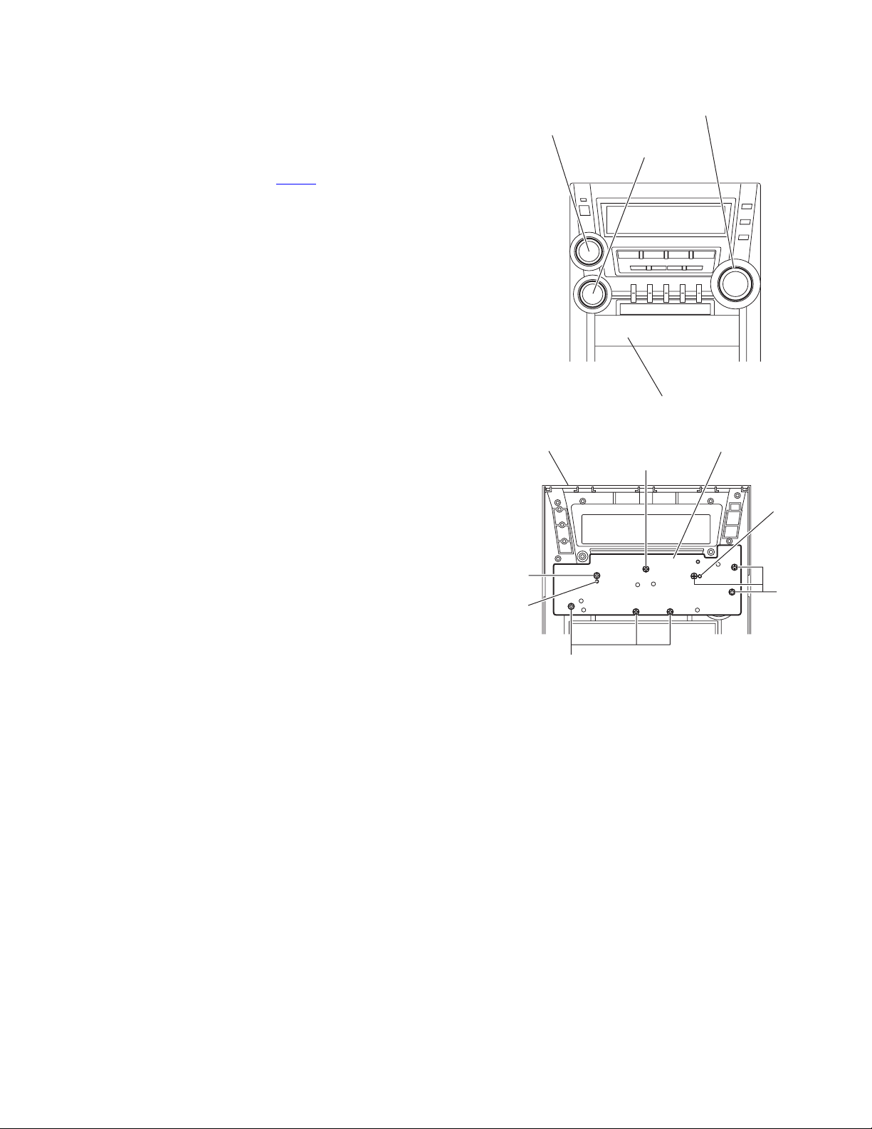
3.1.16 Removing the encoder board
(See Figs.26 to 29)
• Prior to performing the following procedures, remove the metal
cover and front panel assembly.
(1) From the outside of the front panel assembly, pull out the
knobs toward this side. (See Fig.28.)
(2) From the inside of the front panel assembly, disconnect the
card wire from the connector CN902
Fig.26.)
(3) Remove the four screws Z, three screws AA and two
screws AB attaching the each board. (See Figs.26 and 27.)
(4) Take out the FL board with the switch and standby LED
boards.
Reference:
It is not necessary to remove the parallel wires.
(5) Remove the eight screws AC attaching the encoder board.
(See Fig.29.)
Reference:
When attaching the encoder board, align the projections aa of
the front panel assembly in the holes of the encoder board before attaching the screws AC. (See Fig.29.)
on the FL board. (See
Volume knob
Sound mode knob
Preset knob
Front panel assembly
Fig.28
Encoder boardFront panel assembly
AC
AC
aa
aa
AC
AC
Fig.29
(No.MB261)1-17
Page 18

3.1.17 Removing the microphone board
(See Fig.30)
• Prior to performing the following procedure, remove the metal
cover and front panel assembly.
From the inside of the front panel assembly, remove the seven
screws AD and screw AD’ attaching the microphone board.
Reference:
• When attaching the microphone board, align the projections
ab of the front panel assembly in the holes of the microphone board before attaching the screws AD and AD’.
• When attaching the screw AD’, attach the wire holder with it.
Microphone board
AD AD AD
ab
ab
Wire holder
AD'AD
Parallel wire
3.1.18 Removing the headphone board
(See Fig.31)
• Prior to performing the following procedures, remove the metal
cover and front panel assembly.
(1) From the inside of the front panel assembly, remove the
screw AE attaching the headphone board.
(2) Remove the wire holder fixing the parallel wire and take out
the headphone board.
Reference:
After attaching the headphone board, fix the parallel wire with
the wire holder.
3.1.19 Removing the cassette mechanism assembly
(See Fig.31)
• Prior to performing the following procedure, remove the metal
cover and front panel assembly.
(1) From the inside of the front panel assembly, remove the
two screws AF and two screws AG attaching the cassette
mechanism assembly.
Reference:
When attaching the cassette mechanism assembly, align the
projections (ac, ad) in the holes of the cassette mechanism as-
sembly.
ab
Front panel assembly
Cassette mechanism assembly
AF
ad
AF
Front panel assembly
Fig.30
Headphone board
AG
Fig.31
Wire holder
ac
AG
Parallel wire
AE
1-18 (No.MB261)
Page 19

3.2 DVD changer mechanism assembly section
r
r
r
3.2.1 Removing the tray assemblies
(See Figs.1 to 5)
(1) From the top side of the main body, remove the two screws
A from the top cover and release the two joints a on the
both sides of the DVD changer mechanism assembly. (See
Figs.1 and 2.)
(2) Remove the two rods from the top cover and remove the
top cover from the lifter assembly. (See Figs.1 and 2.)
(3) Remove the open det. lever on the left side of the DVD
changer mechanism assembly. (See Fig.3.)
(4) From the right side of the DVD changer mechanism as-
sembly, draw out the tray assemblies toward the front while
pushing the part b of the side (R) assembly. (See Figs.4
and 5.)
Note:
The tray can be locked if all tray assemblies are attached.
(5) From the topside of the DVD changer mechanism assem-
bly, move the stopper tabs c in the direction of the arrow
and release them. Pull out the tray assemblies from the
DVD changer mechanism assembly. (See Fig. 5.)
Note:
Remove the tray assembly from top tray 5 in order.
Reference:
When reattaching the tray assembly, or when removing the
disc remaining inside, refer to another section"3.2.15 Taking
out the disc in the play mode".
Top cove
A
A
Tray assemblies
Tray assembly
Fig.3
b
Fig.4
Open det. leve
Side(R) assembly
a
Lifter assembly
a
Lifter assembly
Fig.1
Fig.2
a
c
Rods
Rods
Top cove
Fig.5
a
(No.MB261)1-19
Page 20

3.2.2 Removing the DVD servo board
(See Figs.6 to 8)
Caution:
Solder the short land sections d on the DVD pickup before disconnecting the card wire extending from the DVD pickup. If
you do not follow this instruction, the DVD pickup may be damaged.
(1) From the topside of the DVD changer mechanism assem-
bly, solder the short land sections d on the DVD pick up.
(See Fig.6.)
(2) From the bottom side of the DVD changer mechanism as-
sembly, disconnect the card wire from the connectors
(CN201
(3) Disconnect the wires from the connectors (CN452
on the DVD servo board. (See Fig.7.)
(4) Remove the screw B attaching the earth wire. (See Fig.7.)
Reference:
(5) Remove the two screws C attaching the DVD servo board.
(See Fig.7.)
(6) From the reverse side of the DVD servo board, release the
lock of the connector CN101
and disconnect the card wire. (See Fig.8.)
Caution:
Unsolder the solders from the short land sections d after reassembling. (See Fig.6.)
, CN451) on the DVD servo board. (See Fig.7.)
, CN453)
After attaching the earth wire, fix it with the spacer as before. (See Fig.7.)
in the direction of the arrow
Short land sections d
DVD changer mechanism assembly
Fig.6
DVD changer mechanism assembly
Card wire
CN452
CN453
DVD pickup
Wires
g
3.2.3 Removing the switch board
(See Fig.7)
• Prior to performing the following procedures, remove the DVD
servo board.
(1) From the bottom side of the DVD changer mechanism as-
sembly, remove the screw D attaching the switch board to
the DVD changer mechanism assembly.
(2) Loosen the screw E attaching the DVD traverse mecha-
nism assembly and take out the switch board while lifting
the section e of the DVD traverse mechanism assembly.
(3) Release the wires from the slots f of the switch board.
Reference:
When reassembling, pass the wire through the section g of the
DVD traverse mechanism assembly.
B
Earth wire
C
CN451
DVD servo board
DVD servo board
Switch board
f
e
CN201
C
DVD traverse mechanism assembly
Fig.7
Card wire
CN101
Lock
D
E
1-20 (No.MB261)
Card wire
Fig.8
Page 21

3.2.4 Removing the motor board
(See Figs.9 and 10)
(1) From the top side of the DVD changer mechanism assem-
bly, remove the two belts from the motor pulleys. (See
Fig.9.)
Note:
Take care not to attach grease on the belt.
(2) Remove the four screws F attaching the motors to the load-
er assembly. (See Fig.9.)
(3) From the bottom side of the DVD changer mechanism as-
sembly, remove the two screws G. (See Fig.10.)
(4) Disconnect the connector CN2
tray switch board and remove the motor board. (See
Fig.10.)
(5) Disconnect the card wire from the connector CN1
motor board. (See Fig.10.)
Note:
When connecting the card wire, let the card wire through the
slots g of the motor board. (See Fig.10.)
Reference:
You need not to remove the tray assemblies, and in such case,
move it.
on the motor board from the
on the
Belt
F
Motor Motor
Motor pulleys
Belt
F
Loader assembly
Fig.9
Motors
3.2.5 Removing the motor
(See Fig. 10)
• Prior to performing the following procedures, remove the motor
board.
(1) From the reverse side of the motor board, unsolder the four
soldered sections h on the motor board.
(2) From the forward side of the motor board, remove the mo-
tors.
Note:
When reattaching the motor, turn the side where the label
should be put to the front side.
Label
Tray switch
board
CN2
CN1
DVD changer mechanism assembly
Motor board
G
g
Card wire
Soldered sections h
G
Motors
Fig.10
Motor board
(No.MB261)1-21
Page 22

3.2.6 Removing the DVD traverse mechanism assembly
(See Fig.11)
• Prior to performing the following procedures, remove the tray
assemblies and DVD servo board.
(1) From the bottom side of the DVD changer mechanism as-
sembly, remove the three screws H attaching the DVD
traverse mechanism assembly.
(2) Remove the card wire from the section i.
(3) Remove the wire from the section j.
(4) Take out the DVD traverse mechanism assembly from the
DVD changer mechanism assembly.
DVD changer mechanism assembly
i
j
H
H
DVD traverse mechanism assembly
Fig.11
1-22 (No.MB261)
Page 23

3.2.7 Removing the DVD pickup
r
(See Figs.12 to 14)
• Prior to performing the following procedures, remove the tray
assemblies, DVD servo board and DVD traverse mechanism
assembly.
(1) From top side of the DVD traverse mechanism assembly,
release the lock of the connector on the DVD pickup and
disconnect the card wire in the direction of the arrow. (See
Fig.12.)
(2) Turn the screw shaft gear in the direction of the arrow 1 to
move the DVD pickup in the direction of the arrow 2. (See
Fig.12.)
(3) Remove the screw J attaching the gear holder. (See
Fig.12.)
(4) Remove the screw K attaching the SS adj. spring. (See
Fig.12.)
(5) Move the DVD pickup in the direction of the arrow and re-
move the screw shaft from the section k on the screw shaft
holder. (See Fig.13.)
(6) Remove the section m of the DVD pickup from the guide
shaft. (See Fig.13.)
(7) Remove the two screws L attaching the rack arm to the
DVD pickup. (See Fig.14.)
(8) Pull the screw shaft from the DVD pickup in the direction of
the arrow. (See Fig.14.)
3.2.8 Attaching the DVD pickup
(See Figs.12 to 14)
(1) Attach the screw shaft to the DVD pickup and attach the
rack arm with the screws L. (See Fig.14.)
Reference:
After attaching the screw shaft to the DVD pickup, attach
the screw shaft collor to the screw shaft. (See Fig.14.)
(2) Attach the section m of the DVD pickup to the guide shaft
first and attach the screw shaft to the section k on the
screw shaft holder. (See Fig.13.)
(3) Attach the gear holder and SS adj. spring with the screws
J and K. (See Fig.12.)
(4) Turn the screw shaft gear to move the DVD pickup toward
the left. (See Fig.12.)
(5) Connect the card wire to the connector on the DVD pickup.
(See Fig.12.)
Screw shaft gear
1
Gear holder
Screw shaft
DVD traverse mechanism assembly
Connector
Card wire
2
KJ
DVD pickup
Fig.12
DVD pickup
m
Screw shaft holder
Fig.13
DVD pickup
SS adj. spring
Guide shaft
k
Rack arm
Screw shaft collo
L
Screw shaft
Fig.14
(No.MB261)1-23
Page 24

3.2.9 Removing the spindle motor board
(See Figs.15 and 16)
• Prior to performing the following procedures, remove the tray
assemblies and DVD traverse mechanism assembly.
(1) From the top side of the DVD traverse mechanism assem-
bly, remove the four screws M attaching the DVD traverse
mechanism assembly to the DVD traverse mechanism
base 3. (See Fig.15.)
(2) Remove the wires from the soldered section n on the spin-
dle motor board. (See Fig.15.)
(3) Remove the screw N attaching the spindle motor board.
(See Fig.15.)
(4) From the bottom side of the DVD traverse mechanism as-
sembly, remove the three screws P attaching the spindle
motor board. (See Fig.16.)
Reference:
When attaching the spindle motor board, let the card wire
through the hole p on the SF motor base. (See Fig.15.)
N
Card wire
SF motor base
M
Spindle motor board
M
p
n
M
Wires
M
DVD traverse mechanism base
DVD traverse mechanism assembly
Fig.15
P
Fig.16
1-24 (No.MB261)
Page 25

3.2.10 Removing the motor
(See Figs.17 and 18)
• Prior to performing the following procedures, remove the tray
assemblies, DVD traverse mechanism assembly, DVD pickup
and spindle motor board.
• Remove the wires of the motor as required.
(1) Remove the middle gear in the direction of the arrow. (See
Fig.17.)
(2) Remove the screw Q and screw R attaching the SF motor
base. (See Fig.17.)
(3) Remove the screw S attaching the motor to the SF motor
base. (See Fig.18.)
(4) Take out the motor from the motor base.
Reference:
After attaching the feed motor, let the wires through the sections q and r on the SF motor base. (See Fig.17.)
SF motor base
Q
Middle
gear
R
Motor
rq
Fig.17
Motor
SF motor base
S
Fig.18
(No.MB261)1-25
Page 26

3.2.11 Removing the side (L) assembly and tray switch board
(See Figs.19 to 21)
• Prior to performing the following procedures, remove the tray
assemblies.
(1) From the topside of the DVD changer mechanism assem-
bly, remove the two screws T attaching the side (L). (See
Fig.19.)
(2) From the left side of the DVD changer mechanism assem-
bly, remove the spacer fixing the tray switch board and motor board. (See Fig.20.)
(3) Disconnect the connector CN3
from the motor board and detach the side (L) in an upward
direction. (See Fig.20.)
(4) Remove the screw U attaching the tray switch board to the
side (L). (See Fig.21.)
(5) Release the joint tab s of the side (L) in the direction of the
arrow 1 and release the joint tab t while removing the tray
switch board in the direction of the arrow 2. (See Fig.21.)
on the tray switch board
SIde(L)
T
T
Fig.19
T
Side(L)
T
CN3
Tray switch board
Motor board
Side(L)
Fig.20
s
1
1-26 (No.MB261)
2
t
Tray switch board
U
Fig.21
Page 27

3.2.12 Removing the side (R) assembly
(See Fig.22 to 26)
• Prior to performing the following procedures, remove the tray
assemblies and DVD servo board.
(1) From the inside of the side (R) assembly, release the two
tabs u of the gear cover and remove the gear cover outward. (See Figs.22 and 23.)
(2) From the right side of the DVD changer mechanism as-
sembly, remove the elevator spring attached to the hook v
of the loader assembly. (See Figs.23 and 24.)
(3) From the top side of the DVD changer mechanism assem-
bly, turn the gear 1 clockwise to move the elevator cam
rearward. (See Fig.24.)
(4) Move the two slots w and joint x of the elevator cam and
remove the elevator cam outward. (See Fig.24.)
(5) Remove the three screws V and detaches the side (R) as-
sembly upward. (See Figs.25 and 26.)
Note:
When reattaching the side (R) assembly, make sure to fit the
shaft (part y) into the slot of the select lever. (See Fig.25.)
Side(R) assembly
u
V
Elevator spring
ww
V
x
Fig.24
y
Select lever
v
Elevator cam
Side(R) assembly
Gear cover
Elevator cam
Loader assembly
Fig.22
Elevator
Fig.23
Gear 1
v
V
Side(R) assembly
Fig.25
V
V
Side(R) assembly
Fig.26
(No.MB261)1-27
Page 28

3.2.13 Removing the lifter assembly
(See Figs.27 to 31)
• Prior to performing the following procedures, remove the tray
assemblies, DVD servo board, side (L) and side (R) assembly.
(1) From the top side of the DVD changer mechanism assem-
bly, turn the gear 1 clockwise to move the lifter assembly
upward. (See Figs.27 and 28.)
(2) Turn the gear 2 clockwise to move the hook toward the
front until it stops. (See Figs.27 and 28.)
(3) Move the hook stopper in the direction of the arrow 2 while
pushing the tab z of the hook stopper to unlock it in the direction of the arrow 1 and release four joints aa to detach
from the rack holder. (See Fig.29.)
(4) Release the rod from part ab. (See Fig.29.)
(5) Turn the gear 1 clockwise again to move the lifter assembly
upward. (See Fig.30.)
(6) Remove the lifter assembly from the DVD changer mecha-
nism assembly upward at the positions ac where the four
pins on the both sides of the lifter assembly fit to the notch-
es of the loader assembly. (See Fig.30.)
(7) Move the lifter assembly in the direction of the arrow and
release it from the hook. (See Fig.31.)
Gear 2
Hook stopper
aa
Rack holder
aa
z
Gear 1
Hook
1
aa
Hook stopper
Fig.29
Lifter assembly
aa
2
Rod(L)
ac
ab
ac
Hook
Gear 2
Lifter assembly
Fig.27
Gear 1
Gear 1
Lifter assembly
Loader assembly
Lifter assembly
Fig.30
ac
ac
Hook stopper
1-28 (No.MB261)
Hook
Fig.31
Hook
Fig.28
Page 29

3.2.14 Removing the rack holder and sensor assembly
r
r
(See Figs.32 to 38)
• Prior to performing the following procedures, remove the tray
assemblies, side (L), side (R) assembly and lifter assembly.
Reference:
If the slide gear of the DVD changer mechanism assembly
places at joint ad of the rack holder, turn the gear 1 counterclockwise to move the slide gear in the direction of the arrow.
Then Remove the rack holder. (See Figs.32 and 33.)
(1) Remove the three screws W attaching the rack holder and
release joint ad from the notch ae. (See Figs.32 and 34.)
Note:
When reattaching the rack holder, do not nip the wires
extending from the sensor assembly. (See Fig.32.)
(2) Remove the two screws X attaching the sensor assembly.
(See Figs.35 and 38.)
(3) Move the sensor assembly in the direction of the arrow to
release from the joint section af. (See Figs.35 and 38.)
(4) Remove the sensor spring attached to the bottom of the
sensor assembly from the boss ag on the slider. (See
Figs.35 and 36.)
(5) Remove the screw Y and Z attaching the sensor board and
SV. resister respectively. (See Fig.37.)
Reference:
Remove the soldered section aj on the sensor board as required. (See Fig.37.)
Note:
• When reattaching the SV. resister, attach the slider to the
sensor bracket and fit the lever on the bottom of the SV. resister into slot ak of the sensor slider. (See Figs.36 and 37.)
• When reattaching the rack holder, turn the gear 1 clockwise
to move the slide gear and slide lever inside the body in the
direction of the arrow. (See Figs.32 and 38.)
• Let the wire extending from the sensor assembly through
notch ah to the bottom of the DVD changer mechanism assembly. (See Figs.35 and 38.)
• Fit pin am of the slide lever into hole ai of the slider on the
bottom of the sensor assembly while attaching the sensor
spring to the boss ag of the slider. (See Figs.36 and 38.)
• Joint section af of the sensor assembly to the notch an of the
DVD changer mechanism assembly. (See Fig.38.)
W
Rack holder
Slide gear
X
Rack holde
ad
Fig.33
Rack holde
ae
ad
Fig.34
ah
Sensor assembly
Slider
W
Wire
Slide gear
ad
W
Fig.32
Gear 1
ag
X
af
Sensor spring
Fig.35
(No.MB261)1-29
Page 30

Slider
ak
ag
Sensor spring
Fig.36
ai
YZ
Sensor board
ak
SV. resister
Slider
aj
Sensor bracket
Fig.37
X
Sensor assembly
X
Sensor gear
an
1-30 (No.MB261)
af
am
Sensor spring
ai
ag
ah
Slide lever
Fig.38
Page 31

3.2.15 Taking out the disc in the play mode
r
(See Fig.39 to 42)
Reference:
Refer to "Removing the tray assemblies".
(1) From the top side of the DVD changer mechanism assem-
bly, remove the top cover.
(2) Unlock the tray assemblies and draw out the tray assem-
blies toward the front.
(3) From the top side of the DVD changer mechanism assem-
bly, turn the gear 1 clockwise to move the lifter assembly
upward. (See Fig.39.)
(4) Turn the gear 2 clockwise to move the sub tray remaining
inside the lifter assembly toward the front, then pull out.
(See Fig.39.)
(5) Take out the disc on the sub tray. (See Fig.40.)
(6) After clearing away the disc, insert the sub tray into the
main tray. (See Fig.41.)
Note:
When reattaching the sub tray, move the tray stopper on
the bottom of the main tray in the direction of the arrow
to lock the sub tray certainly. (See Figs.41 and 42.)
(7) Push the tray assembly toward the DVD changer mecha-
nism assembly and reattach.
Tray assembly
Tray stopper
Tray assembly
Disc
Sub tray
Fig.40
Main tray
Gear 2
Gear 1
Sub tray
Sub tray
Fig.41
Tray stoppe
Fig.39
Fig.42
(No.MB261)1-31
Page 32

3.3 Cassette mechanism assembly
3.3.1 Removing the Play/Record & Clear head
(See Fig.1~3)
(1) While moving the trigger arm on the right side of the head
mount in the direction of the arrow, turn the flywheel R
counterclockwise until the head mount comes ahead and
clicks.
(2) The head turns counterclockwise as you turn the flywheel
R counterclockwise (See Fig.2 and 3).
(3) Disconnect the flexible wire from connector CN31
head amplifier & mechanism control board.
(4) Remove the spring from the back of the head.
(5) Loosen the azimuth screw for reversing attaching the head.
(6) Remove the head on the front side of the head mount.
on the
Cassette mechanism assembly
Fig.1
Head
Fly wheelR
Trigger armHead mount
Flexible wire
Fly wheel R
Fig.2
Azimuth screw
Head
for reversing
Spring
CN31
Head amplifer & mecha control board
Fig.3
1-32 (No.MB261)
Page 33

3.3.2 Removing the head amplifier & mechanism control board
(See Fig.4)
(1) Turn over the cassette mechanism assembly and remove
the three screws A attaching the head amplifier & mechanism control board.
(2) Disconnect the flexible wire from connector CN31
head amplifier & mechanism control board.
(3) Disconnect connector CN32
anism control board from connector CN1
board.REFERENCE: If necessary, unsolder the 4-pin wire
soldered to the main motor.
3.3.3 Removing the main motor
(See Fig.4~7)
(1) Remove the two screws B .
(2) Half raise the motor and remove the capstan belt from the
motor pulley.
ATTENTION:
Be careful to keep the capstan belt from grease. When reassembling, refer to Fig.6 and 7 for attaching the capstan belt.
Head amplifier & mecha control board
of the head amplifier & mech-
on the reel pulse
on the
Main motor assembly
Capstan belt
Fig.5
Main motor assembly
CN31
Flexible wire
A
AA
Fig.4
CN32
4pin wire
B
Main motor assembly
Motor pulley
Capstan belt
Fig.6
Main motor assembly
Fly wheel
Capstan belt
Motor pulley
Fig.7
(No.MB261)1-33
Page 34

3.3.4 Removing the flywheel
(See Fig.8, 9)
• Prior to performing the following procedure, remove the head
amplifier & mechanism control board and the main motor assembly.
(1) From the front side of the cassette mechanism, remove the
slit washers attaching the capstan shaft L and R. Pull out
the flywheels backward.
Fly wheel R Fly wheel L
Fig.8
Fly wheel R
Capstan shaft R Capstan shaft L
Slit washer
Fig.9
3.3.5 Removing the reel pulse board and solenoid
(See Fig.10)
• Prior to performing the following procedure, remove the head amplifier & mechanism control board.
(1) Remove the screw C.
(2) Release the tab a, b, c, d and e retaining the reel pulse board.
(3) Release the tab f and g attaching the solenoid on the reel pulse board.
(4) The reel pulse board and the solenoid come off.
Fly wheel L
bc
a
Solenoid
g
f
d
Reel pulse board
C
e
Fig.10
1-34 (No.MB261)
Page 35

3.3.6 Reattaching the Play/ Record & Clear head
r
r
(See Fig.11~13)
(1) Reattaching the head mount assembly.
a) Change front of the direction cover of the head
mount assembly to the left (Turn the head forward).
b) Fit the bosses O', P', Q', U' and V' on the head mount
assembly to the holes P and V, the slots O, U and Q
of the mechanism sub assembly (See Fig.11 to 13).
CAUTION:
To remove the head mount assembly, turn the direction
cover to the left to disengage the gear. If the gear can not
be disengaged easily, push up the boss Q' slightly and
raise the rear side of the head mounts slightly to return
the direction lever to the reversing side.
(2) Tighten the azimuth screw for reversing.
(3) Reattach the spring from the back of the Play/ Record &
Clear head.
(4) Connect the flexible wire to connector CN31
amplifier & mechanism control board.
on the head
U' Q'
Head mount assembly
Head mount assembly
O'
Fig.11
P'
P'
V'
V'
Direction cove
Spring
Flexible wire
V
O
P
Q
Head
Direction cove
U
Fig.12
Azimuth screw for reversing
Head mount
CN31
Fig.13
Head amplifier &
mechanism control board
(No.MB261)1-35
Page 36

SECTION 4
ADJUSTMENT
4.1 Measurement instruments required for adjustment
(1) Low frequency oscillator,
This oscillator should have a capacity to output 0dBs to
600Ω at an oscillation frequency of 50Hz-20kHz.
(2) Attenuator impedance : 600Ω
(3) Electronic voltmeter
(4) Distortion meter
(5) Frequency counter
(6) Wow flutter meter
(7) Test tape
VTT703L : Head azimuth
VT712 : Tape speed and running unevenness(3kHz)
VT724 : Reference level (1kHz)
(8) Blank tape
TYPEl : AC-225
TYPEll : AC-514
(9) Torque gauge : For play and back tension
FWD(TW2111A), REV(TW2121a) and
FF/REW(TW2231A)
(10) Test disc
VT-501
CTS-1000
4.2 Measurement conditions
Power supply voltage : AC110V / AC127V / AC220V
AC230V ~ AC240V
(Adjustable with the voltage selector)
50Hz / 60Hz
Reference output :
Reference frequency
and input level
Measurement output
terminal
*Load resistance : 4Ω
4.3 Radio input signal
AM frequency : 400Hz
AM modulation : 30%
FM frequency : 400Hz
FM frequency deviation : 22.5kHz
Speaker : 0.775V/4Ω
:
Headphone : 0.077V/32Ω
: 1kHz, AUX : -8dBs
: at Speaker J200
4.4 Tuner section
FM Band cover : 87.50 MHz~108.00 MHz
AM Band cover : 531 kHz~1,710 kHz (at 9kHz step)
530 kHz~1,710 kHz (at 10kHz step)
Voltage applied to tuner : +B : DC5.7V
VT : DC 12V
Reference measurement
output
Input positions : AM : Standard loop antenna
4.5 Standard measurement positions of volume and switch
Function switch : to Tape
Beat cut switch : to Cut
Super Bass/Active hyper Bass : to OFF
Bass Treble : to Center
Adjustment of main volume to
reference output
4.6 Precautions for measurement
(1) Apply 30pF and 33kΩ to the IF sweeper output side and
0.082 F and 100kΩ in series to the sweeper input side.
(2) The IF sweeper output level should be made as low as pos-
sible within the adjustable range.
(3) Since the IF sweeper is a fixed device, there is no need to
adjust this sweeper.
(4) Since a ceramic oscillator is used, there is no need to per-
form any MPX adjustment.
(5) Since a fixed coil is used, there is no need to adjust the FM
tracking.
(6) The input and output earth systems are separated.
In case of simultaneously measuring the voltage in both of
the input and output systems with an electronic voltmeter
for two channels, therefore, the earth should be connected
particularly.
(7) In the case of BTL connection amplifier, the minus terminal
of speaker is not for earthing. Therefore, be sure not to connect any other earth terminal to this terminal. This system
is of an OTL system.
(8) For connecting a dummy resistor when measuring the out-
put, use the wire with a greater code size.
(9) Whenever any mixed tape is used, use the band pass filter
(DV-12).
: 26.1mV(0.28V)/3Ω
FM : TP1 (hot) and TP2 (GND)
: VOL : 28
1-36 (No.MB261)
Page 37

4.7 Cassette mechanism adjustment
Head azimuth
adjustment screw
(Forward side)
Mecha control board
Motor speed
VR37
Head azimuth
adjustment screw
(Reverse side)
Head azimuth
adjustment screw
(Forward side)
R/P head, Erase head
Head azimuth
adjustment screw
(Reverse side)
CN31
BIAS adjust
VR31
C308
R327
VR31
R313
Q302
R315
C316
C319
R314
C221
L301
C121
SW1
C314
R104
Q305
C313
PP300
D340
C310
R310
C107
L303
R102
R121
R221
R303
R108
R335
R353
C113
R304
Q343
R339
R302
C301
C103
C207
R110
Q342
C304
R208
C105
C205
R301
SW2
C106
R306
D1
R106
R101
C104
CN34
C306
Q344
R105
C102
R344
R205
Q345
R345
C307
R336
C340
R346
R107
R206
C206
W1
Q346
R305
C110
VR37
R210
C300
C341
R109
R372
Q372
C120
C371
P1
CN33
R116
C109
IC32
CN31
Q371
C101
R371
C374
C220
R376
R216
Q375
C376
C202
C204
C201
W1
R201
C342
D375
R204
C213
R207
Q376
R375
C209
IC1
FW100
R338
R337
CN32
R202
CN1
C203
C210
R340
C331
R342
R347
Q347
SW6
R343
SW5
R341
IC33
(No.MB261)1-37
Page 38

4.7.1 Mechanism section
Item Condition Measurement method Ref.value
Head
azimuth
Test tape
: VT703L (8kHz)
Output terminal
: Speaker out
1. Playback the test tape VT703L (8kHz).
2. Adjust to maximum output level by azimuth
adjustment screw for forward side and reverse
side.
Maximum
output
3. This adjustment is adjust by adjustment screw
of forward side and adjustment screw of
reverse side.
Tape speed
Test tap
: VT712 (3kHz)
Output terminal
Playback the test tape VT712 (3kHz) at end of
forward side, adjust to 2,940~3,90Hz indication
of frequency counter by VR37.
2,940 to
3,090Hz
: Speaker out or
Headphone out
Adjustment
position
Only adjust
at changed
head
VR37
Item Condition Measurement method Ref.value
Tape speed
deviation at
FWD/REV
Test tape
: VT712 (3kHz)
Output terminal
Playback the test tape VT712 (3kHz) at end
of forward and reverse, tape speed deviation
should be less than 6.0Hz.
Less than
6.0Hz
: Speaker out or
Headphone out
Wow & Flutter
Test tape
: VT712 (3kHz)
Output terminal
Playback the test tape VT712 (3kHz) at
start of forward and reverse, Wow & Flutter
are should be less than 0.25% (WRMS).
Less than
0.25%
(WRMS)
: Speaker out or
Headphone out
Adjustment
position
VR31
1-38 (No.MB261)
Page 39

4.7.2 Electrical adjustment
Item Condition Measurement method Ref.value
Item Condition Measurement method Ref.value
Recording
Recording
BIAS
BIAS
adjustment
adjustment
Forward or Reverse
Forward or Reverse
Test tape
Test tape
:AC-514 TYPE
:AC-514 TYPE
:AC-225 TYPE
:AC-225 TYPE
Output terminal
Output terminal
Recording head
Recording head
1. Set the test tape(AC-514 TYPE and
1. Set the test tape(AC-514 TYPE and
AC-225 TYPE ), then make REC/PAUSE
AC-225 TYPE ), then make REC/PAUSE
condition.
condition.
2. Connect 100 to recording head by series,
2. Connect 100 to recording head by series,
then connect to VTVM for measurement
then connect to VTVM for measurement
the current.
the current.
3. After setting, start the recording by release
3. After setting, start the recording by release
the PAUSE, in this time bias current adjust
the PAUSE, in this time bias current adjust
to next fig. by VR31 for Lch and VR32 for
to next fig. by VR31 for Lch and VR32 for
Rch.
Rch.
4.0uA (TYPE ) and 4.20uA (TYPE ).
4.0uA (TYPE ) and 4.20uA (TYPE ).
AC-225
AC-225
:4.20uA
:4.20uA
AC-514
AC-514
:4.0uA
:4.0uA
Adjustment
Adjustment
position
position
VR31
VR31
R/P
R/P
playback
playback
frequency
frequency
response
response
4.7.3 Electrical response confirmation
Reference frequency
Reference frequency
: 1kHz / 10kHz
: 1kHz / 10kHz
(Reference: -20dB)
(Reference: -20dB)
Test tape
Test tape
: AC-514 TYPE
: AC-514 TYPE
Input terminal
Input terminal
playback
playback
frequency
frequency
response
response
Item Condition Measurement method Ref.value
Recording
bias
current
Forward or Reverse
Test tape
: TYPE (AC-514)
Measurement
terminal
: BIAS test point on
printed circuit board
1. Set the test tape (AC-514 TYPE ), then
1. Set the test tape (AC-514 TYPE ), then
make REC/PAUSE condition.
make REC/PAUSE condition.
2. Release the PAUSE, then start recording
2. Release the PAUSE, then start recording
the 1kHz and 10kHz of reference frequency
the 1kHz and 10kHz of reference frequency
from oscillator.
from oscillator.
3. Playback the recorded position, 1kHz and
3. Playback the recorded position, 1kHz and
10kHz output deviation should -1dB 2dB
10kHz output deviation should -1dB 2dB
to readjust by VR31 for Lch and VR32 for
to readjust by VR31 for Lch and VR32 for
Rch.
Rch.
1. Change BIAS1 and 2, confirm the frequency
should be change.
2. Set the test tape (AC-514 TYPE ), then
make REC/PAUSE condition.
3. Confirm the frequency should 100Hz 6kHz
at BIAS test point on printed circuit board.
Output
Output
deviation
deviation
1kHz/10kHz
1kHz/10kHz
:-1dB 2dB
:-1dB 2dB
100 kHz
6 kHz
VR31
VR31
Adjustment
position
Erase
current
(reference
value)
Forward or Reverse
Rec condition
Test tape
: AC-514 TYPE
: AC-225 TYPE
Measurement
terminal
: Both side of Erase
head
1. Set the test tape (AC-514 TYPE and
AC-225 TYPE ), then make REC/PAUSE
condition.
2. Release the PAUSE to REC condition,
connect 1W to ERASE head by series, then
confirm the erase current at both side of
erase head.
TYPE
: 120 mA
TYPE
: 75 mA
(No.MB261)1-39
Page 40

4.8 Service mode
4.8.1 Confirming contents
(1) System micon reset
(2) System micon cold start
(3) FL display check
(4) Micon version check
(5) DVD region check
(6) DVD test mode
4.8.2 Confirming methods
(1) System micon reset
When DVD mechanism stuck, this may solve the problem without removing/inserting power cord.
Press the
STANDBY/ON, CANCEL
and PAUSE buttons on the main unit
simultaneously.
System micon is initialized.
(2) System micon cold start
This function clears all user setting, and return to initial setting.
• Daily timer, REC timer
• Tuner preset
• SEA preset
• Last condition (Source, Volume)
Press the SET UP, "4" and "0" buttons
twice on the remote controller at standby.
" COLD SET "
This unit returns to initial setting.
(3) FL display check
This enables all FL segment light up.
Press the SET UP, "4" and "+10" buttons
on the remote controller at standby.
FL indication
1-40 (No.MB261)
All of the FL displays light up.
Page 41

(4) Micon version check
r
You can confirm Micon version and destination.
Insert the power cord in an outlet.
Press the SET UP, "4" and DIMMER
buttons on the remote controller.
System micon version is indicated on
the FL display.
Press the SET UP, "4" and DIMMER
buttons on the remote controller.
DVD mechanism micon version is indicated
on the FL display.
Press the SET UP, "4" and DIMMER
buttons on the remote controller.
DVD backend firmware version is indicated
on the FL display.
(5) DVD region check
You can confirm DVD region number.
Press the POWER and DVD LEVEL
buttons on the main unit at standby.
FL indication
REGION
Press the SET UP, "4" and DIMMER
buttons on the remote controller.
Model number is indicated
on the FL display.
Press the SET UP, "4" and DIMMER
buttons on the remote controller.
Destination is indicated on the FL display.
DVD region number is indicated on the on screen display.
(Example) "3U ver.0334 HS / HX-GD7 / FMU-SD7-11"
DVD unit numbe
Firmware model
Firmware version
DVD destination
(No.MB261)1-41
Page 42

(6) DVD test mode
Insert the power cord in an outlet while
pressing the SET and buttons on
the main unit.
Status: You can check DVD unit condition.
DVD unit condition is indicated on the FL
display.
Initialize (Normal):
Initialize user setting
Press the PAUSE button on the main unit.
(Example) "TEST 3U 30"
FL indication
(Example)
Press the STANDBY/ON button on the
main unit or remote controller.
Disconnect the power cord in an outlet.
Insert the power cord in an outlet.
Press the STANDBY/ON button on the
main unit or remote controller.
Initialization is complete.
Disc reading preset condition
0: DVD/CD learned
1: only CD learned
2: only DVD learned
3: DVD/CD not learned
DVD region number
DVD destination
"TEST 3U 300"
Initialize (Permanent):
Initialize "QUICK PLAY" setting
Press the button on the main unit for two seconds.
FL indication
(Example)
"TEST 3U 333"
Press the STANDBY/ON button on the
main unit or remote controller.
Disconnect the power cord in an outlet.
Insert the power cord in an outlet.
Press the STANDBY/ON button on the
main unit or remote controller.
Insert a new VT-501 disc, play this disc.
Eject the VT-501 disc.
Insert a new CTS-1000 disc, play this disc.
Eject the CTS-1000 disc.
Press the STANDBY/ON button on the
main unit or remote controller.
1
1-42 (No.MB261)
Initialization is complete.
2
Page 43

3
CD laser:
CD laser current display
Press the "4" button on the remote controller.
DVD laser:
DVD laser current display
Press the "5" button on the remote controller.
DVD jitter:
DVD single-layer jitter display
Press the "6" button on the remote controller.
EEPROM (B):
EEPROM data display (Backward)
Press the "7" button on the remote controller.
EEPROM (F):
EEPROM data display (Forward)
Press the "8" button on the remote controller.
Temperature:
Pickup temperature display
Press the "9" button on the remote controller.
DVD jitter:
DVD jitter (D/L - S/L) display
Press the "10" button on the remote controller.
FL indication
" "
FL indication
" "
FL indication
" "
FL indication
" "
FL indication
" "
FL indication
" "
FL indication
" "
EEPROM ini.:
EEPROM initialize
Press the "+10" button on the remote controller.
Monitor:
Monitor change
Press the "0" button on the remote controller.
STOP:
Disc stop
Press the STOP button on the remote controller.
FL indication
" CHECK "
PLAY:
Laser & jitter display
Press the PLAY button on the remote controller.
Check mode is complete.
Press the STANDBY/ON button
on the main unit or remote controller.
FL indication
" FFFF FFFF "
FL indication
" "
FL indication
" "
(No.MB261)1-43
Page 44

1
2
Device key:
Program DEVICE KEY code
Press the button on the main unit.
Device key check:
Check device key checksum
Press the MENU button twice on the remote controller.
Micon version check:
Check micon version number
Press the MENU button on the remote controller.
STANDBY/ON LED blink.
PC application run.
Automatically power off
Wait until PC application complete
FL indication
(Example) " "
Device key check is complete.
FL indication
(Example) " SSSS "
S: System micon version
Press the MENU button on
the remote controller.
FL indication
(Example) " MMMM BBBB "
Micon version check is complete.
Reference:
If never programmed,
"FFFF" will appear.
M: Mechanism micon
version
B: Backend firmware
FL display check:
Check all FL segments
Press the MENU button on the remote controller.
Check mode
Press the MENU button on the remote controller.
FL indication
" CHECK "
Check mode
Press the MENU button on the remote controller.
START PLAY:
Start playing
Press the "1" button on the remote controller.
WOBBLE:
WOBBLE display
Press the "2" button on the remote controller.
All of the FL displays light up.
FL display check is complete.
FL indication
" CHECK "
FL indication
" "
1-44 (No.MB261)
3
Page 45

4.8.3 Indicating check for FL display
No. Function FL display Note
1 SOURCE
DVD-VIDEO
DVD-AUDIO
CD
MP3
WMA
VCD
SVCD
DVD (JPEG)
TAPE
AUX
AM
FM
2 TUNER
PRESET MEMOERY
PRESET MEMOERY
PRESET MEMOERY
3 TAPE
PLAY
REVERSE
FF/REW
MUSIC SCAN
REC
DISC REC
DISC REC STOP
1
2.
3
4
1:
1
2:
3
4
1
2.
3
4
1:
1
2:
3
4
C
D
1
2.
1:
1
2:
3
4
1
2.
1
2
2.
1
2:
3
4
If MP3 time is over 100 minutes, show "--:--".
1
2.
1
2
2.
1
2:
3
4
If WMA time is over 100 minutes, show "--:--".
V
D
1
2.
1:
1
2:
3
4
without PBC
V
D
1
2.
S
V
1
2.
S
V
1
2.
1
2.
1
2
2.
T
A
A
U
X
A
M
F
M
TTU
N
E
U
N
E
S
E
P
S
T
O
T
A
T
A
E
V
T
A
T
A
T
A
DRI
S
C
1:
P
1
1
R
R
T
1R2
P
P
E
R
P
P
P
RSEEC
P
B
C
with PBC
1
2:
3
4
without PBC
P
B
C
with PBC
J
P
E
G
E
I
N
6
0
2
: PRESET NUMBER
0
8.
0
0
: PRESET NUMBER
F
M
A
M
BLINKING
BLINKING
E
D
E
E
E
E
E
"DISC REC FINISHED" SCROLL
4 VOLUME
UP/DOWN
MAX
MIN
RHYTHM AX
ON
OFF
SUBWOOFER
LEVEL CHANGE
LEVEL CHANGE
LEVEL CHANGE
LEVEL CHANGE
AT LEVEL 0
AT LEVEL 2
SOUND MODE
DANCE
HALL
STADIUM
ROCK
POP
CLASSIC
USER1
USER2
USER3
OFF
V
O
L
U
M
E
3
0
V
O
L
U
M
E
M
A
X
V
O
L
U
M
E
M
I
N
R
H
Y
T
H
M
A
X
O
N
O
F
F
S
U
B
W
O
O
F
E
R
S.
W
O
O
F
E
R
0
S.
W
O
O
F
E
R
1
S.
W
O
O
F
E
R
2
M
I
N
L
E
V
E
L
M
A
X
L
E
V
E
L
D
A
N
C
E
H
A
L
L
S
T
A
D
I
U
M
R
O
C
K
P
O
P
C
L
A
S
S
I
C
U
S
E
R
1
U
S
E
R
2
U
S
E
R
3
O
F
F
(No.MB261)1-45
Page 46

No. FL display
Function Note
4 3D PHONIC
3D ACTION
3D DRAMA
3D THEATER
3D PHONIC OFF
3
D
A
C
3
D
D
R
3
D
T
H
E
3
D
O
F
Note: DVD-A cannot be activated 3D-Phonic.
Also at Karaoke condition, 3D-PHONIC is
T
I
O
N
A
M
A
A
T
E
R
F
TONE SETTING
TONE MEMORY
TONE MEMORY
TONE MEMORY
TONE MEMORY
TONE MEMORY
DVD LEVEL
LEVEL 1
LEVEL 2
LEVEL 3
KARAOKE
KARAOKE ON
KARAOKE OFF
MIC MIX
MIC MIX
MIC OFF
ECHO
ECHO
ECHO OFF
KEY CONTROL
KEYCON
5 SLEEP
SLEEP 10 120
CLOCK
ADJUST
SET
SET
DAILY TIMER
SELECT
SET
SET
SET
SET
SET
SET
SET
SET
SET
S
E
A
C
O
N
T
B
A
S
S
T
R
E
U
S
E
M
E
M
D
V
D
L
D
V
D
L
D
V
D
L
K
A
R
A
O
F
M
I
C
M
I
C
E
C
H
E
C
H
O
K
E
Y
C
S
L
E
E
P
1
1
C
L
O
C
D
A
I
L
Y
O
N
O
N
S
E
O
F
F
O
F
F
S
E
D
I
T
A
A
U
X
T
U
N
E
T
U
N
E
S
E
D
1
G
1
S
E
D
1
G
1
S
E
D
1
G
1
S
E
V
O
L
U
M
S
E
0
0
R
1
O
R
Y
E
V
E
E
V
E
E
V
E
O
K
E
F
M
I
X
O
F
F
O
O
F
O
N
2:
0
0
2.
0
0
K
O
T
I
M
1
2:
1
2:
T
1
2:
1
2:
T
S
C
P
E
I
N
R
F
R
A
T
T
T
T
T
T
T
E
T
O
RANGE: -3 0 +3
RANGE: -3 0 +3
NUMBER BLINKING
L
1
L
2
L
3
RANGE: 1 3
F
RANGE: -6 0 +6
RANGE: 10/20/30/60/90/120
HOUR BLINKING
MINUTE BLINKING
K
E
R
0
0
HOUR BLINKING
0
0
MINUTE BLINKING
0
0
HOUR BLINKING
0
0
MINUTE BLINKING
BLINKING (ALL)
BLINKING
BLINKING
M
BLINKING
M
BLINKING
1
BLINKING DISC (D )
1
BLINKING GROUP (G )
1
BLINKING TRACK (T )
--/5/10/15
K
1-46 (No.MB261)
Page 47

No. FL display
Function Note
5 REC TIMER
SELECT
SET
SET
SET
SET
SET
SET
R
E
O
N
O
N
O
F
F
O
F
F
T
U
T
U
F
M
3
T
C
T
E
S
T
E
S
R
E
N
R
E
N
T
E
S
1
0
T
E
S
6 TEST (ROM) by Remocon
"B332"
M
M
S
Y
S
C
O
N
O
D
U
L
E
B
A
K
E
N
D
D
L
V
E
R
TEST (REGION)
R
E
G
I
O
N
I
M
E
R
1
2:
0
0
HOUR BLINKING
1
2:
0
0
MINUTE BLINKING
1
2:
0
0
HOUR BLINKING
1
2:
0
0
MINUTE BLINKING
F
M
A
M
0
8.
0
O
K
BLINKING
BLINKING
0
BLINKING
ROM correction +3 CHARACTORS
4 CHARACTORS (including ROM CORR)
BACKEND VERSION 4 CHARACTORS
J / E / A / US / UW / UX
0/1/2/3/4/5/6
7 DVD STATUS
OPEN
CLOSE
NO DISC
DISC CHANGE
TOC READING
ROM CORRECTION
(SYSCON)
ROM CR. OK
ROM CR. NG
ROM CORRECTION
(MECHA MICON)
ROM CR. OK
ROM CR. NG
BACKEND "UPGRADE"
"UNKNOWN" DISC
REGION ERROR
8 DVD VIDEO
STOP
+10KEY INPUT
PLAY
PLAY (MENU)
PAUSE
SEARCH
RESUME STOP
RESUME PLAY
M
M
O
P
E
N
C
L
O
S
E
N
O
S
Y
S
Y
E
E
C
A
R
E
.
1
.
1
2.
1.
1
2.
1
2.
.
1
2.
D
I
S
C
D
I
S
C
2
R
E
A
D
I
N
G
U
P
G
R
A
D
E
S
C
O
N
S
C
O
N
U
P
G
R
C
H
O
C
H
E
U
P
G
R
N
'
T
G
I
O
N
3
4.
1:
3
4.
1:
3
4.
:
3
4.
1:
O
E
R
A
D
E
K
R
R
O
A
D
E
P
L
A
E
R
S
T
O
2
3:
4
P
L
A
2
3:
4
:
S
T
O
2
3:
4
SOURCE CD and CURRENT ONLY
SOURCE CD and CURRENT ONLY
1
SOURCE CD and CURRENT ONLY
SOURCE CD and CURRENT ONLY
SOURCE CD and CURRENT ONLY
SOURCE CD and CURRENT ONLY
K
SOURCE CD and CURRENT ONLY
R
SOURCE CD and CURRENT ONLY
SOURCE CD and CURRENT ONLY
SOURCE CD and CURRENT ONLY
R
SOURCE CD and CURRENT ONLY
SOURCE CD and CURRENT ONLY
Y
SOURCE CD and CURRENT ONLY
R
SOURCE CD and CURRENT ONLY
P
After TOC READING
5
Y
5
TIME BLINKING
P
5
RESUME OFF BEFORE PLAY
(No.MB261)1-47
Page 48

No. FL displayFunction Note
9 DVD AUDIO
STOP
+10KEY INPUT
PLAY
PLAY (MENU)
PAUSE
SEARCH
RESUME STOP
RESUME PLAY
DOWNMIX PROHIBITED
WATERMARK
.
.
1
.
1
2.
3
4.
.
.
1
2.
3
4.
1
2.
3
4.
.
.
1
2.
3
4.
L
R
N
O
S
T
O
P
After TOC READING
S
T
O
P
1:
2
3:
4
5
P
L
A
Y
1:
2
3:
4
5
TIME BLINKING
:
:
S
T
O
P
RESUME
1:
2
3:
4
5
RESUME OFF BEFORE PLAY
O
N
L
Y
A
U
D
I
O
.
10 VCD
V
D
1
2.
1:
2
3:
4
5
STOP (without PBC)
STOP (with PBC)
PLAY (PBC OFF)
PLAY (PBC ON)
PAUSE (PBC OFF)
PAUSE (PBC ON)
SEARCH (NORMAL)
SEARCH (PBC DISC)
+10KEY INPUT
V
D
V
D
1
2.
V
D
1
2.
V
D
1
2.
V
D
1
2.
V
D
1
2.
:
V
D
1
2.
V
D
1
.
1:
1:
1:
P
B
2
3:
4
P
B
2
3:
4
P
B
:
P
B
2
3:
4
DISPLAY TOTAL TIME
C
5
C
5
TIME BLINKING
C
C
5
SVCD
S
V
1
2.
1:
2
3:
4
5
STOP (without PBC)
STOP (with PBC)
PLAY (PBC OFF)
PLAY (PBC ON)
PAUSE (PBC OFF)
PAUSE (PBC ON)
SEARCH (NORMAL)
SEARCH (PBC DISC)
+10KEY INPUT
S
V
S
V
1
2.
S
V
1
2.
S
V
1
2.
S
V
1
2.
S
V
1
2.
:
S
V
1
2.
S
V
1
.
1:
1:
1:
P
B
2
3:
4
P
B
2
3:
4
P
B
:
P
B
2
3:
4
DISPLAY TOTAL TIME
C
5
C
5
TIME BLINKING
C
C
5
11 MP3/WMA
STOP
STOP
GROUP SEARCH
GROUP SEARCH
PLAY
PLAY
PLAY
PLAY
PLAY
PAUSE
SEARCH (GROUP)
SEARCH (TRACK)
12 JPEG
STOP
PLAY
SEARCH
1-48 (No.MB261)
1.
2.
1.
1.
2.
1.
1.
1.
1.
GROUP FILE NAME SCROLL
1.
SST
O
P
GROUP FILE NAME SCROLL
1.
T
O
P
TRACK FILE NAME SCROLL
TRACK "SONG TITLE" SCROLL
TRACK "PERFORMER" SCROLL
TRACK "ALBUM TITLE" SCROLL
2
3.
2
3.
1.
2
4.
1.
2
3.
2
3.
:
:
SJT
:
3:
3:
4
5
4
5
TIME BLINKING
OEP
P
G
Page 49

No. FL display
Function Note
13 PROGRAM
PROGRAM MODE
DISC INPUT (10key)
GROUP INPUT
TRACK INPUT
STOP
PR
D
1.
.
D
1.
1.
D
1.
1.
D
1.
1.
PLAY
FULL MEMORY
FOUGLRL
14 RANDOM
RANDOM MODE
RANRDAONM
SEARCH
PLAY
15 REPEAT
2.
2.
2.
2.
2.3.3.
1:
1:
1:
REPEAT 1 track
REPEAT 1 track
REPEAT 1 chapter
REPEAT 1 title
REPEAT 1 group
1.
1.
1.
1.
REPEAT 1 disc
REPEAT ALL
REPEAT A-B
A
:
:
:
:
DOM
2
3:
3:
2
3:
2
3:
3:
M
Group # Blink, 10-key and ENTER key input
Track # Blink, 10-key and ENTER key input
1
1
DEPEND ON DISC TYPE
: MOVING
DEPEND ON DISC TYPE
4
5
CD/VCD case
4
5
MP3/WMA case
4
5
DVD case
4
5
DVD case
4
5
MP3/WMA case
DEPEND ON DISC TYPE
DEPEND ON DISC TYPE
DEPEND ON DISC TYPE
16 KARAOKE RESERVE
OSD DISPLAY
RESERVE ENTRY
RESERVE PLAY
RESERVE END
17 PROGRESSIVE
INTERLACE
PROGRESSIVE
18 DEMO
DEMO START
IPNRTOEGRRLEASCSE
D
E
M
O
S
T
A
W
E
L
C
O
M
E
T
O
J
V
C
C
D
P
L
A
D
I
S
C
1
P
L
D
I
S
C
D
V
D
P
L
A
D
I
S
C
2
P
L
D
I
S
C
IV
R
T
Y
A
Y
Y
A
Y
NO CHANGE FROM CURRENT DISPLAY
NO CHANGE FROM CURRENT DISPLAY
DEPEND ON DISC TYPE
NO CHANGE FROM CURRENT DISPLAY
Random select from DVD/MP3/JPEG/WMA/CD
Random select from DVD/MP3/JPEG/WMA/CD
(No.MB261)1-49
Page 50

No. FL displayFunction Note
M
P
3
P
L
A
18
DEMO OFF
D
I
S
C
3
D
I
S
C
W
M
A
P
D
I
S
C
4
D
I
S
C
J
P
E
G
P
D
I
S
C
5
D
I
S
C
T
U
N
E
R
F
M
T
U
N
E
R
A
M
T
A
P
A
U
X
A
U
X
3
D
P
H
D
A
N
C
H
A
L
S
T
A
D
I
R
O
C
P
O
P
C
L
A
S
S
U
S
E
R
U
S
E
R
U
S
E
R
S.
W
O
O
F
S.
W
O
O
F
M
A
X
L
S.
W
O
O
F
S.
W
O
O
F
M
I
N
L
R
H
Y
T
H
M
O
N
D
E
M
O
Y
P
L
A
Y
L
A
Y
P
L
A
Y
L
A
Y
P
L
A
Y
F
M
A
M
E
I
N
O
N
I
C
E
L
U
M
K
I
C
1
2
3
E
R
1
E
R
2
E
V
E
L
E
R
1
E
R
0
E
V
E
L
A
X
O
F
F
BEEP
B
E
E
P
O
BEEP ON
BEEP OFF
B
E
E
P
N
O
F
F
TRAY LOCK
L
O
C
K
E
LOCK
UNLOCK
U
N
L
O
D
C
K
E
D
1-50 (No.MB261)
Page 51

No. FL display
19
DVD TEST MODE
TEST START
Function Note
T
S
E
T
(Version info)
T
S
E
A. EEPROM INITIALIZE
(NORMAL)
B. EEPROM INITIALIZE
(FULL)
T
T
S
E
T
T
S
E
T
T
S
E
T
@
#
By AC cord on with holding SET and
: VERSION
@: FE learning condition
#: REGION
@
#
@
#
@
#
3
#
By pressing PAUSE (Front)
0
By pressing and holding (Front) for 2-sec
3
DEVICE KEY DISPLAY
VERSION DISPLAY
VERSION DISPLAY
FL ALL ON
CHECK MODE
START PLAY
WOBBLE
CD LASER current
DVD LASER current
DVD-SL jitter
EEPROM (BWD)
EEPROM (FWD)
Temperature
DVD-DL/SL jitter
EEPROM initialize
Monitor change
STOP
OPEN/CLOSE
PLAY
REGION CHANGE
DEVICE KEY
WRITING MODE
WRITING
COMPLETE (OK)
By pressing MENU (Remote)
a
a
a
a
By pressing MENU (Remote)
aaaa: Syscon
c
c
b
b
b
b
c
c
By pressing MENU (Remote)
bbbb: Mechacon, cccc: Backend
By pressing MENU (Remote)
H
E
C
C
H
C
K
E
C
K
By pressing MENU (Remote)
By pressing 1 (Remote)
By pressing 2 (Remote)
By pressing 4 (Remote)
By pressing 5 (Remote)
By pressing 6 (Remote)
By pressing 7 (Remote)
By pressing 8 (Remote)
By pressing 9 (Remote)
By pressing 10 (Remote)
F
F
F
F
F
F
F
F
By pressing +10 (Remote)
By pressing 0 (Remote)
H
E
C
C
K
By pressing STOP (Front or Remote)
By pressing OPEN/CLOSE (Front)
By pressing PLAY (Front or Remote)
O
A
N
G
H
C
E
K
By AV COMPULINK
By pressing (Front)
By DEVICE KEY (AV COMPULINK) JIG
Automatically power off
(No.MB261)1-51
Page 52

SECTION 5
TROUBLESHOOTING
This service manual does not describe TROUBLESHOOTING.
1-52 (No.MB261)
Page 53

(No.MB261)1-53
Page 54

Victor Company of Japan, Limited
AV & MULTIMEDIA COMPANY AUDIO/VIDEO SYSTEMS CATEGORY 10-1,1chome,Ohwatari-machi,Maebashi-city,371-8543,Japan
(No.MB261)
Printed in Japan
WPC
 Loading...