

Page 1
YA207200412
SERVICE MANUAL
COLOUR TELEVISION
HV-Z29J4,
123
456
789
RETURN+
TV/VIDEO MENU
DISPLAY
CHANNEL VOLUME
CINEMA
SOUND
SURROUND
MODE
F. T/L
STROBE
HV-Z29J4
HV-Z29J4
/H,
/S
BASIC CHASSIS
MM2
DVDPIP T V
0
SUB-P
OK
BACK
SUB-P
BASS ZOOM
?
TOP MENU
TABLE OF CONTENTS
1 PRECAUTION. . . . . . . . . . . . . . . . . . . . . . . . . . . . . . . . . . . . . . . . . . . . . . . . . . . . . . . . . . . . . . . . . . . . . . . . . 1-3
2 SPECIFIC SERVICE INSTRUCTIONS . . . . . . . . . . . . . . . . . . . . . . . . . . . . . . . . . . . . . . . . . . . . . . . . . . . . . . 1-4
3 DISASSEMBLY . . . . . . . . . . . . . . . . . . . . . . . . . . . . . . . . . . . . . . . . . . . . . . . . . . . . . . . . . . . . . . . . . . . . . . . 1-6
4 ADJUSTMENT . . . . . . . . . . . . . . . . . . . . . . . . . . . . . . . . . . . . . . . . . . . . . . . . . . . . . . . . . . . . . . . . . . . . . . . 1-12
5 TROUBLESHOOTING . . . . . . . . . . . . . . . . . . . . . . . . . . . . . . . . . . . . . . . . . . . . . . . . . . . . . . . . . . . . . . . . . 1-37
COPYRIGHT © 2004 Victor Company of Japan, Limited
No.YA207
2004/12
Page 2
SPECIFICATION
Items Contents
Dimensions ( W × H × D ) 73.1cm × 49.5cm × 62.2cm
Mass 46.0kg
TV RF System B, G, I, D, K, M
Colour System PAL / SECAM / NTSC 3.58 / NTSC 4.43
Stereo System A2 (B/G), NICAM (B/G, I, D/K)
Receiving
Frequency
Intermediate
Frequency
Colour Sub
Carrier
Teletext System FLOF (Fastext), TOP, WST (World Standard System)
Power Input AC 110V - AC240V, 50Hz/60Hz
Power Consumption 177W (Standby : 2.1W)
Picture Tube Visible size : 67.6cm (Measured diagonally), H: 55.4cm × V: 41.4cm
High Voltage 31.0kV±0.2kV [at zero beam current]
Speaker 6.5cm × 13cm, oval type × 2
Audio Power Output
Aerial Input 75 Ω unbalanced, coaxial
Video / Audio
[Input-1/2/3/4]
Video / Audio
Output
Headphone Jack 3.5mm Stereo mini jack × 1
AV COMPULINK 3.5mm mini jack × 1
Remote Control Unit RM-C1851 (AA/R6 dry cell battery × 2)
Component Video
VHF Low
VHF High
UHF
CATV
VIF
SIF
PAL
SECAM
NTSC
[Input-2/3]
1125i / 750p
625p / 525p
625i / 525i
S-Video
[Input-1/4]
Video
Audio
Video
Audio
46.25MHz ~ 168.25MHz
175.25MHz ~ 463.25MHz
471.25MHz ~ 863.25MHz
Mid (X ~ Z+2, S1 ~ S10) / Super (S11 ~ S20) / Hyper (S21 ~ S41) bands
38.0MHz (B, G, I, D, K, L)
32.26MHz (5.74MHz: B), 32.15MHz (5.85MHz: G), 31.45MHz (6.55MHz: I)
32.15MHz (5.85MHz: D), 32.15MHz (5.85MHz: K)
4.43MHz
4.40625MHz / 4.25MHz
3.58MHz / 4.43MHz
10W + 10W
RCA pin jack × 6
Y : 1V (p-p) (Sync signal: ±0.35V(p-p), 3-value sync.), 75 Ω
Pb/Pr : ±0.35V(p-p), 75 Ω
Y : 1V (p-p), Positive (Negative sync provided), 75 Ω
Pb/Pr : 0.7V(p-p), 75 Ω
Mini-DIN 4 pin connector × 2
Y: 1V (p-p), Positive (Negative sync provided), 75 Ω
C: 0.286V (p-p) (Burst signal), 75 Ω
1V (p-p), Positive (Negative sync provided), 75 Ω, RCA pin jack × 4
500mV (rms), High impedance, RCA pin jack × 8
1V (p-p), Positive (Negative sync provided), 75 Ω, RCA pin jack × 1
500mV (rms), Low impedance, RCA pin jack × 2
Design & specifications are subject to change without notice.
1-2 (No.YA207)
Page 3

SECTION 1
PRECAUTION
1.1 SAFETY PRECAUTIONS
(1) The design of this product contains special hardware,
many circuits and components specially for safety
purposes. For continued protection, no changes should be
made to the original design unless authorized in writing by
the manufacturer. Replacement parts must be identical to
those used in the original circuits. Service should be
performed by qualified personnel only.
(2) Alterations of the design or circuitry of the products should
not be made. Any design alterations or additions will void
the manufacturer's warranty and will further relieve the
manufacturer of responsibility for personal injury or
property damage resulting therefrom.
(3) Many electrical and mechanical parts in the products have
special safety-related characteristics. These
characteristics are often not evident from visual inspection
nor can the protection afforded by them necessarily be
obtained by using replacement components rated for
higher voltage, wattage, etc. Replacement parts which
have these special safety characteristics are identified in
the parts list of Service manual. Electrical components
having such features are identified by shading on the
schematics and by ( ) on the parts list in Service
manual. The use of a substitute replacement which does
not have the same safety characteristics as the
recommended replacement part shown in the parts list of
Service manual may cause shock, fire, or other hazards.
(4) Don't short between the LIVE side ground and
ISOLATED (NEUTRAL) side ground or EARTH side
ground when repairing.
Some model's power circuit is partly different in the GND.
The difference of the GND is shown by the LIVE : ( ) side
GND, the ISOLATED (NEUTRAL) : ( ) side GND and
EARTH : ( ) side GND.
Don't short between the LIVE side GND and ISOLATED
(NEUTRAL) side GND or EARTH side GND and never
measure the LIVE side GND and ISOLATED (NEUTRAL)
side GND or EARTH side GND at the same time with a
measuring apparatus (oscilloscope etc.). If above note will
not be kept, a fuse or any parts will be broken.
(5) If any repair has been made to the chassis, it is
recommended that the B1 setting should be checked or
adjusted (See B1 POWER SUPPLY check).
(6) The high voltage applied to the picture tube must conform
with that specified in Service manual. Excessive high
voltage can cause an increase in X-Ray emission, arcing
and possible component damage, therefore operation
under excessive high voltage conditions should be kept to
a minimum, or should be prevented. If severe arcing
occurs, remove the AC power immediately and determine
the cause by visual inspection (incorrect installation,
cracked or melted high voltage harness, poor soldering,
etc.). To maintain the proper minimum level of soft X-Ray
emission, components in the high voltage circuitry
including the picture tube must be the exact replacements
or alternatives approved by the manufacturer of the
complete product.
(7) Do not check high voltage by drawing an arc. Use a high
voltage meter or a high voltage probe with a VTVM.
Discharge the picture tube before attempting meter
connection, by connecting a clip lead to the ground frame
and connecting the other end of the lead through a 10kΩ
2W resistor to the anode button.
(8) When service is required, observe the original lead dress.
Extra precaution should be given to assure correct lead
dress in the high voltage circuit area. Where a short circuit
has occurred, those components that indicate evidence of
overheating should be replaced. Always use the
manufacturer's replacement components.
(9) Isolation Check (Safety for Electrical Shock Hazard)
After re-assembling the product, always perform an
isolation check on the exposed metal parts of the cabinet
(antenna terminals, video/audio input and output terminals,
Control knobs, metal cabinet, screw heads, earphone jack,
control shafts, etc.) to be sure the product is safe to operate
without danger of electrical shock.
a) Dielectric Strength Test
The isolation between the AC primary circuit and all metal
parts exposed to the user, particularly any exposed metal
part having a return path to the chassis should withstand a
voltage of 3000V AC (r.m.s.) for a period of one second. (.
. . . Withstand a voltage of 1100V AC (r.m.s.) to an
appliance rated up to 120V, and 3000V AC (r.m.s.) to an
appliance rated 200V or more, for a period of one second.)
This method of test requires a test equipment not generally
found in the service trade.
b) Leakage Current Check
Plug the AC line cord directly into the AC outlet (do not use
a line isolation transformer during this check.). Using a
"Leakage Current Tester", measure the leakage current
from each exposed metal part of the cabinet, particularly
any exposed metal part having a return path to the chassis,
to a known good earth ground (water pipe, etc.). Any
leakage current must not exceed 0.5mA AC (r.m.s.).
However, in tropical area, this must not exceed 0.2mA AC
(r.m.s.).
Alternate Check Method
Plug the AC line cord directly into the AC outlet (do not
use a line isolation transformer during this check.). Use
an AC voltmeter having 1000Ω per volt or more
sensitivity in the following manner. Connect a 1500Ω
10W resistor paralleled by a 0.15µF AC-type capacitor
between an exposed metal part and a known good earth
ground (water pipe, etc.). Measure the AC voltage
across the resistor with the AC voltmeter. Move the
resistor connection to each exposed metal part,
particularly any exposed metal part having a return path
to the chassis, and measure the AC voltage across the
resistor. Now, reverse the plug in the AC outlet and
repeat each measurement. Any voltage measured must
not exceed 0.75V AC (r.m.s.). This corresponds to
0.5mA AC (r.m.s.).
However, in tropical area, this must not exceed 0.3V AC
(r.m.s.). This corresponds to 0.2mA AC (r.m.s.).
AC VOLTMETER
(HAVING 1000 /V,
OR MORE SENSITIVITY)
0.15 F AC-TYPE
PLACE THIS PROBE
1500 10W
GOOD EARTH GROUND
ON EACH EXPOSED
ME TAL PAR T
(No.YA207)1-3
Page 4

SECTION 2
SPECIFIC SERVICE INSTRUCTIONS
2.1 FEATURES
D.I.S.T. (Digital Image Scaling Technology)
This system uses line interpolation to double the number of
scanning lines and achieve high resolution, flicker-free picture.
ZOOM
This function can change the screen size according to the
picture aspect ratio.
DIGITAL VNR
This function cuts down the amount of noise in the original
picture.
Super DigiPure
This function uses the latest in digital technology to give you a
natural-looking picture.
PULL DOWN
This function displays a cinema film picture more smoothly and
naturally on the screen.
2.2 MAIN DIFFERENCE LIST
Dolby Virtual
This function makes you enjoy sounds with Virtual Dolby
Surround sound.
3D CINEMA SURROUND
This function makes you enjoy sounds with a widerambience.
SUPER BASS
This function can choose the SUPER BASS mode which
emphasises the bass sound.
RETURN +
This function can set a channel you frequently view to the
Return Channel and you can view that channel at any time with
one-touch.
AI ECO SENSOR
This function can adjust this TV so that the screen
automatically adjusts to the optimum contrast according to the
brightness of your room. This function reduces eye strain and
the power consumption of this TV.
Item HV-Z29J4 HV-Z29J4/H HV-Z29J4/S
Power Plug Type Round 2-pin type UK 3-pin type ←
MAIN PWB SMM-1251A-H2 ← SMM-1252A-H2
1-4 (No.YA207)
Page 5

2.3 TECHNICAL INFORMATION
2.3.1 MAIN CPU PIN FUNCTION [IC001 : MI-COM PWB ASS'Y]
Pin
Pin name I/O Function
No.
1 TCK -- Not used 65 D2 I/O Data bit for PP-RAM/SD-RAM
2 TMS -- Not used 66 D12 I/O Data bit for PP-RAM/SD-RAM
3 TDI -- Not used 67 D10 I/O Data bit for PP-RAM/SD-RAM
4 TDO -- Not used 68 VSS33 -- GND
5 P2.8 I Remote control 69 VDD33 I 3.3V
6P2.9 I
7P2.10 I
8P2.11 I
9 P2.12 I Receive data for AV COMPULINK 73 RSTIN I Reset for main CPU
10 P2.13 O Power on /off control (ON: L) 74 P3.0 O Clock for Inter IC control bus (for I-P)
11 P2.14 I
12 P2.15 I Main power detection (Detect : L) 76 P3.2 I Remote control
13 VSS33 -- GND 77 P3.3 O Headphone muting (Muting: H)
14 VDD33 I 3.3V 78 P3.4 O Audio muting (Muting: H)
15 P4.5 O Not used 79 P3.5 O Audio muting (Muting: H)
16 A20 O Not used 80 P3.6 O Not used
17 A19 O Address bit for PP-RAM/SD-RAM 81 P3.7 O I-P converter reset (ON : L )
18 A18 O Address bit for PP-RAM/SD-RAM 82 P3.8 O Power LED lighting (for stand-by) (ON : L)
19 A17 O Address bit for PP-RAM/SD-RAM 83 P3.9 O Power LED lighting (for operation) (ON : L)
20 VSS25 -- GND 84 VSS33 -- GND
21 VDD25 I 2.5V 85 VDD33 I 3.3V
22 A16 O Address bit for PP-RAM/SD-RAM 86 VSS25 -- GND
23 A8 O Address bit for PP-RAM/SD-RAM 87 VDD25 I 2.5V
24 A7 O Address bit for PP-RAM/SD-RAM 88 TXD0 O Not used
25 A9 O Address bit for PP-RAM/SD-RAM 89 RXD0 I Not used
26 A6 O Address bit for PP-RAM/SD-RAM 90 P3.12 O Not used
27 A5 O Address bit for PP-RAM/SD-RAM 91 P3.13 I/O Data for Inter IC control bus (for Memory)
28 A10 O Address bit for PP-RAM/SD-RAM 92 P3.15 O Clock for Inter IC control bus (for Memory)
29 A11 O Address bit for PP-RAM/SD-RAM 93 P5.14 I RGB input of EXT-2 detection (Detect : L)
30 A12 O Address bit for PP-RAM/SD-RAM 94 P5.15 I Headphone connection detection (Connect: H)
31 VSS33 -- GND 95 TRIG_IN I RGB input of EXT-1 detection (Detect : L)
32 VDD33 I 3.3V 96 TRIG_OUT O Attenuation level select for RF splitter (ON : H)
33 A4 O Address bit for PP-RAM/SD-RAM 97 P6.2 O Notifies bus free state (Stop mode: H)
34 A3 O Address bit for PP-RAM/SD-RAM 98 P6.3 O Clock for Inter IC control bus (for Service mode)
35 A2 O Address bit for PP-RAM/SD-RAM 99 P6.4 I/O Data for Inter IC control bus (for Service mode)
36 A1 O Address bit for PP-RAM/SD-RAM 100 P6.5 O MSP reset (Reset: H)
37 A0 O Address bit for PP-RAM/SD-RAM 101 P6.6 I/O Data for Inter IC control bus
38 A13 O Address bit for PP-RAM/SD-RAM 102 VSYNC I Vertical sync
39 A14/RAS O Row address strobe for SD-RAM access 103 HSYNC I Horizontal sync
40 A15/CAS O Column address strobe for SD-RAM access 104 COR/RSTOUT O Not used
41 VSS33 -- GND 105 BLANK O Ys for OSD /Teletext (blanking)
42 VDD33 I 3.3V 106 VDD33 I 3.3V
43 MEMCLK O Clock for SD-RAM 107 VSS33 -- GND
44 CSSDRAM O Chip select signal for SD-RAM device 108 XTAL1 I System clock (6MHz)
45 CLKEN O Enable for memory clock 109 XTAL2 O System clock (6MHz)
46 CSROM O Chip select for PP-ROM device 110 VSSA -- GND
47 RD O External memory read strobe for PP-ROM 111 VDDA I 2.5V
48 UDQM O Write disable for high byte 112 R O Red for OSD / Teletext
49 LDQM O Write disable for low byte 113 G O Green for OSD / Teletext
50 WR O Memory write strobe 114 B O Blue for OSD / Teletext
51 D15 I/O Data bit for PP-RAM/SD-RAM 115 VSSA -- GND
52 VSS33 -- GND 116 VDDA I 2.5V
53 VDD33 I 3.3V 117 CVBS2 I Composite video for WSS
54 D7 I/O Data bit for PP-RAM/SD-RAM 118 VSSA -- GND
55 D0 I/O Data bit for PP-RAM/SD-RAM 119 VDDA I 2.5V
56 D14 I/O Data bit for PP-RAM/SD-RAM 120 CVBS1B I Ground for CVBS1A
57 D8 I/O Data bit for PP-RAM/SD-RAM 121 CVBS1A I Composite video for Teletext decoder
58 D6 I/O Data bit for PP-RAM/SD-RAM 122 VSSA -- GND
59 D1 I/O Data bit for PP-RAM/SD-RAM 123 VDDA I 2.5V
60 VSS33 -- GND 124 P5.0 I AFT voltage for Main tuner
61 VDD33 I 3.3V 125 P5.1 I AFT voltage for Sub tuner
62 D13 I/O Data bit for PP-RAM/SD-RAM 126 P5.2 I Room brightness voltage for AI ECO SENSOR
63 D9 I/O Data bit for PP-RAM/SD-RAM 127 P5.3 I I-P converter power error detect (detect : L)
64 D5 I/O Data bit for PP-RAM/SD-RAM 128 TMODE I Test mode
Key scan for front control : CH+, Volume-, TV/VIDEO (On: L)
Key scan for front control : CH-, Volume-, Volume+ (On: L)
Key scan for front control : MENU, Volume+, TV/VIDEO (On: L)
Low B short / CRT neck Protection detection (Detect : L)
Pin
Pin name I/O Function
No.
70 D4 I/O Data bit for PP-RAM/SD-RAM
71 D3 I/O Data bit for PP-RAM/SD-RAM
72 D11 I/O Data bit for PP-RAM/SD-RAM
75 P3.1 I/O Data for Inter IC control bus (for I-P)
(No.YA207)1-5
Page 6
SECTION 3
DISASSEMBLY
3.1 DISASSEMBLY PROCEDURE
3.1.1 REMOVING THE REAR COVER
(1) Unplug the power cord.
(2) Remove the 15 screws [A] as shown in Fig.2.
(3) Withdraw the REAR COVER toward you.
3.1.2 REMOVING THE AV TERMINAL BOARD
• Remove the REAR COVER.
(1) Remove the 12 screws [B] as shown in Fig.2.
(2) Remove the ANTENA TERMINAL pin jack from back side
of the AV TERMINAL BOARD.
(3) Remove the BASS SPEAKER OUT terminal from back
side of the AV TERMINAL BOARD.
(4) Pull out the AV TERMINAL BOARD rear side.
3.1.3 REMOVING THE CHASSIS
• Remove the REAR COVER.
(1) Slightly raise the both sides of the chassis by hand and
remove the 2 claws under the both sides of the CHASSIS
from the front cabinet.
(2) Withdraw the CHASSIS backward.
(If necessary, take off the wire clamp, connectors etc)
3.1.4 REMOVING THE SPEAKER
• Remove the REAR COVER.
(1) Remove the 2 screws [C] as shown in Fig.2.
(2) Remove the SUPPORT BRACKET.
(3) Remove the 4 screws [D] as shown in Fig.2.
(4) Remove the speaker.
3.1.6 WIRE CLAMPING AND CABLE TYING
(1) Be sure to clamp the wire.
(2) Never remove the cable tie used for tying the wires
together. Should it be inadvertently removed, be sure to tie
the wires with a new cable tie.
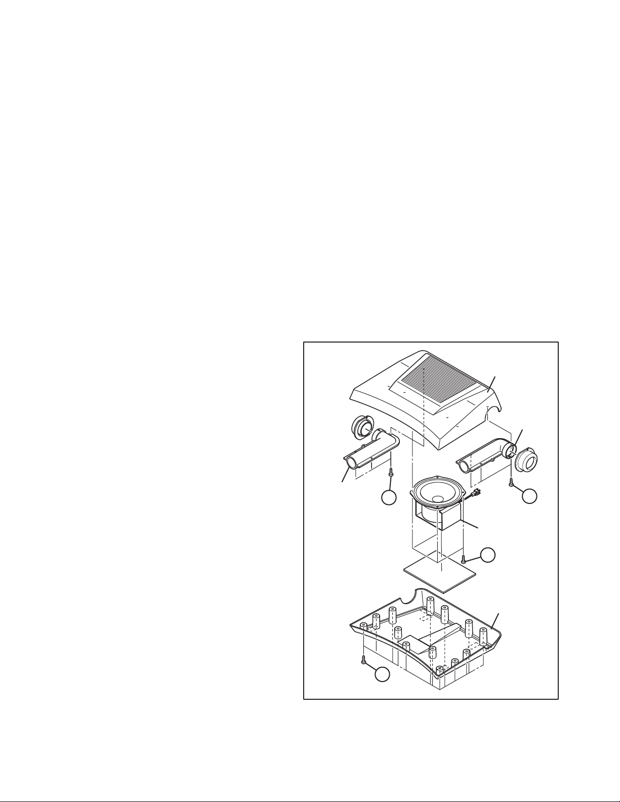
3.1.7 REMOVING THE WOOFER UNIT REAR COVER
(1) Remove the 9 screws [H] as shown in Fig.1.
(2) Remove the SEAKER UNIT REAR COVER.
3.1.8 REMOVING THE WOOFER SPEAKER
(1) Remove the 4 screws [J] as shown in Fig.1.
(2) Remove the WOOFER SPEAKER.
3.1.9 REMOVING THE DUCT
(1) Remove the 3 screws [K] as shown in Fig.1.
(2) Remove the DUCT.
(3) Remove the other side DUCT by same method.
BASS TOP
DUCT
3.1.5 CHECKING THE PW BOARD
• To check the back side of the PW Board.
(1) Pull out the CHASSIS. (Refer to REMOVING THE CHASSIS).
(2) Remove the CONTROL BASE.
(3) Turn down the front side to make the chassis stand
perpendicularly.
(4) Check the solder side of MAIN PWB and POWER & DEF
PWB.
CAUTION:
• When erecting the CHASSIS, be careful so that there will be
no contacting with other PW Board.
• Before turning on power, make sure that the wire connector
is properly connected.
• When conducting a check with power supplied, be sure to
confirm that the CRT EARTH WIRE(BRAIDED ASS'Y) is
connected to the CRT SOCKET PWB.
DUCT
K
WOOFER SPEAKER
J
BASS BOTTOM
H
Fig.1
K
1-6 (No.YA207)
Page 7
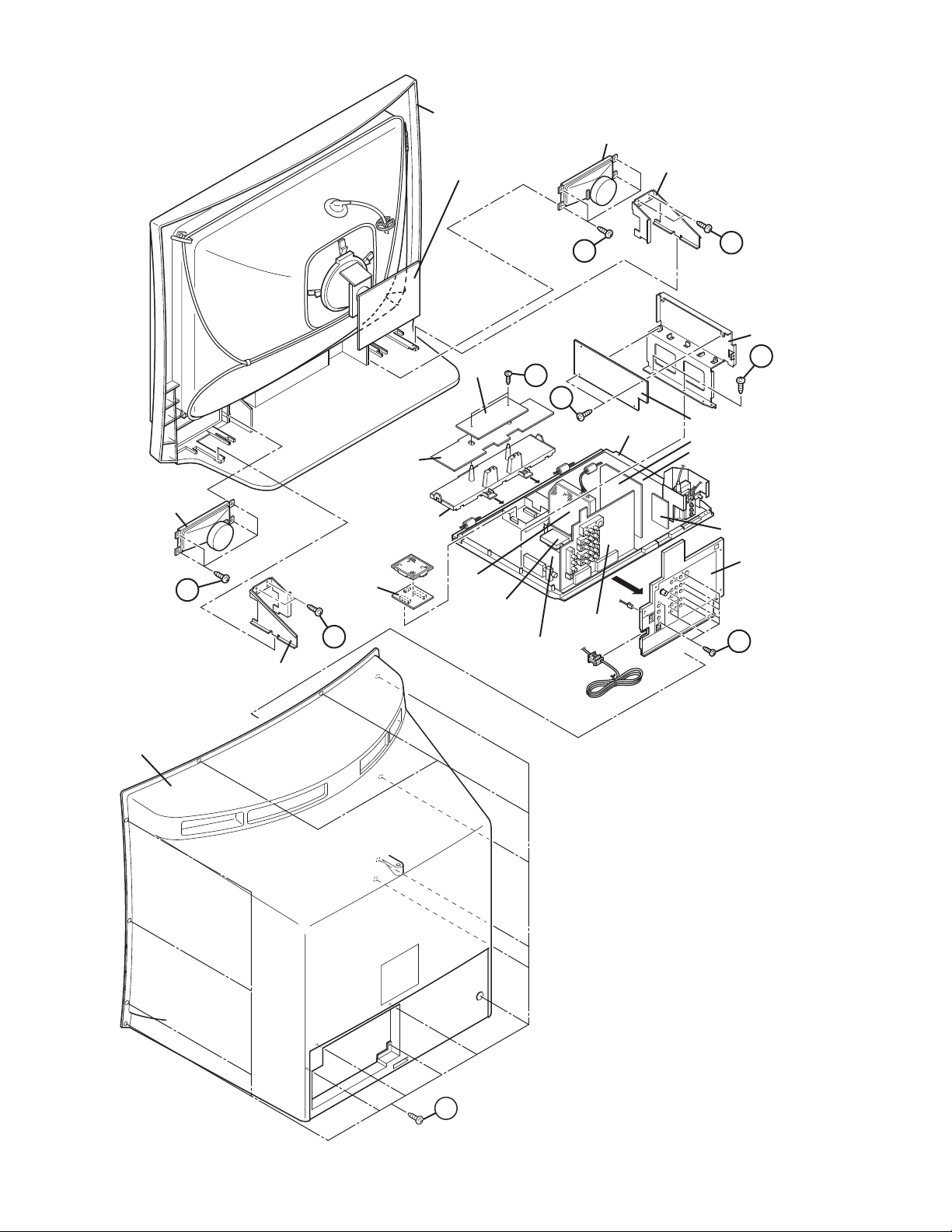
FRONT CABINET
SPEAKER
SPEAKER
CRT SOCKET PWB
POWER SW
PWB
G
D
SUPPORT BRACKET
C
LINE FILTER BASE
E
F
CHASSIS BASE
CONTROL PWB
D
MICOM PWB
FRONT
CONTROL BASE
C
DIST PWB
SUB TUNER
PWB
MAIN PWB
AV SW PWB
LINE FILTER PWB
DEF OSC PWB
POWER & DEF PWB
EHT PWB
AV TERMNAL BOARD
B
SUPPORT BRACKET
REAR COVER
A
Fig.2
(No.YA207)1-7
Page 8
3.2 MEMORY IC REPLACEMENT
• This model uses the memory IC.
• This memory IC stores data for proper operation of the video and drive circuits.
• When replacing, be sure to use an IC containing this (initial value) data.
3.2.1 MEMORY IC REPLACEMENT PROCEDURE
1. Power off
Switch off the power and disconnect the power plug from the
AC outlet.
2. Replace the memory IC
Be sure to use the memory IC written with the initial setting
values.
3. Power on
Connect the power plug to the AC outlet and switch on the
power.
4. System constant check and setting
NOTE:
• It must not adjust without signal.
• Before entering the SERVICE MODE, confirm that the
setting of PIP/TV/DVD switch is at the "TV" side.
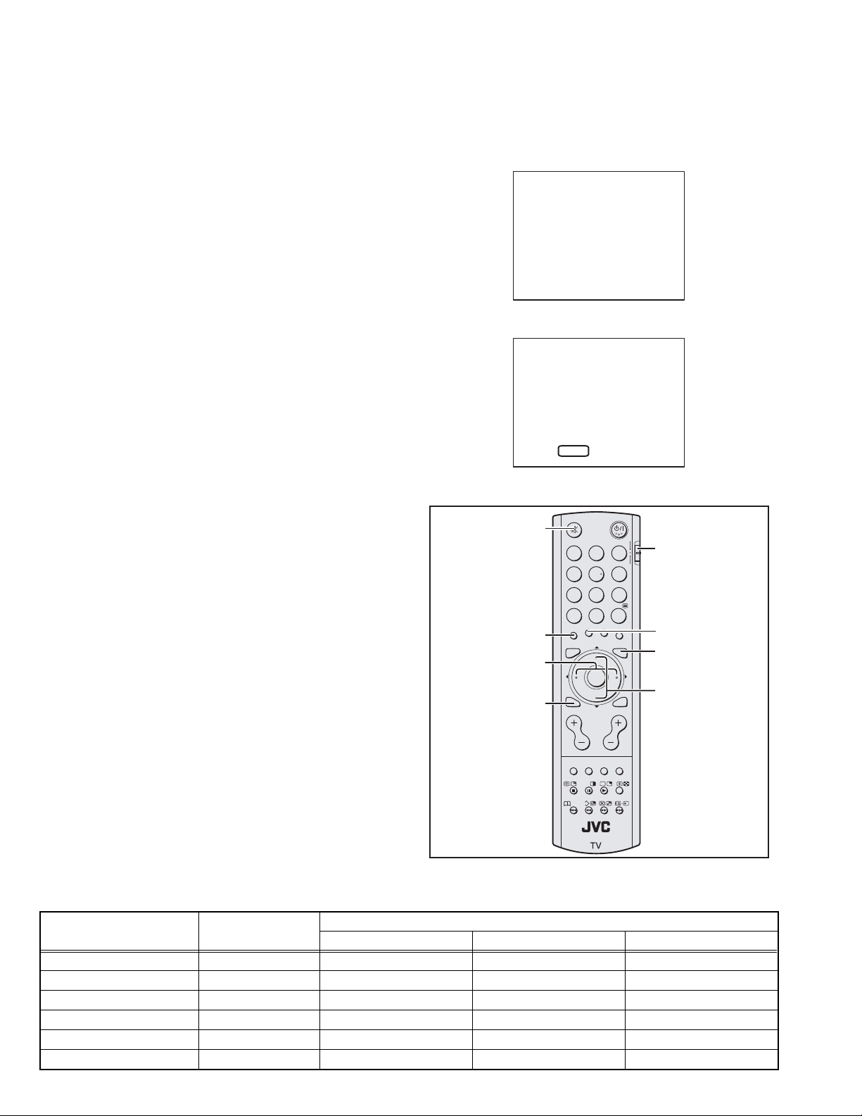
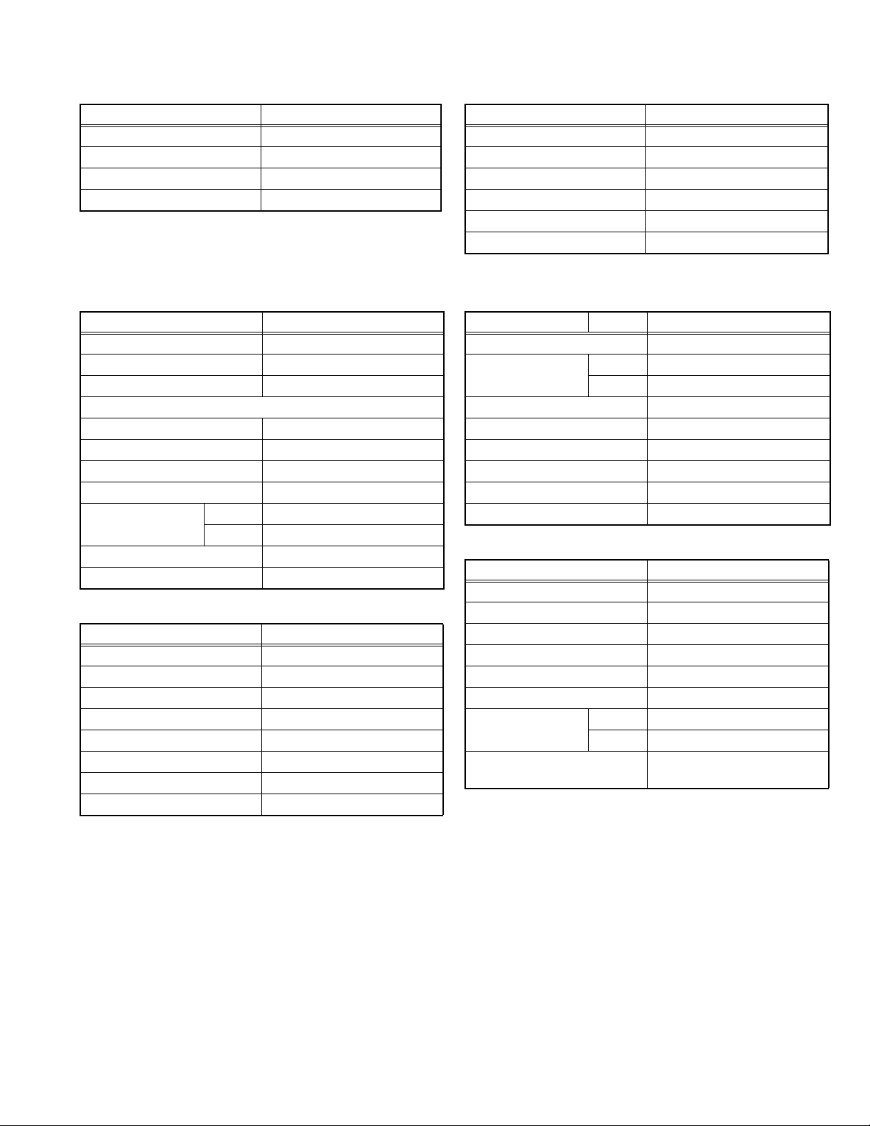
(1) Press the [DISPLAY] key and the [MUTING] key of the
REMOTE CONTROL UNIT simultaneously.
(2) The SERVICE MODE screen of Fig. 1 will be displayed.
(3) While the SERVICE MODE is displayed, press the
[DISPLAY] key and [MUTING] key simultaneously, and
the SYSTEM CONSTANT SET screen of Fig. 2 will be
displayed.
(4) Check the setting values of the SYSTEM CONSTANT
SETTING. If the value is different, select the setting item
with the [ FUNCTON/] key, and set the correct value
with the [ FUNCTON/] key.
(5) Press the [MENU] key to memorize the setting value.
(6) Press the [DISPLAY] key twice, and return to the normal
screen.
5. Receiving channel setting
Refer to the OPERATING INSTRUCTIONS and set the
receive channels (Channels Preset) as described.
FUNCTION /
6. User settings
Check the user setting items according to the given in page
later.
Where these do not agree, refer to the OPERATING
INSTRUCTIONS and set the items as described.
7. SERVICE MODE setting
Verify what to set in the SERVICE MODE, and set whatever is
necessary (Fig.1).
Refer to the SERVICE ADJUSTMENT for setting.
SERVICE MENU
1. IF
3. AUDIO
5. VSM &SSM PRESET
7. 3DNR
9. SHIPPING(OFF)
1-9 : SELECT i : EXIT
SYSTEM CONSTANT SET
1. P MUTE YES
- / + : STORE i : EXIT
MENU
MUTING
123
456
789
RETURN+
ZOOM
DISPLAY
TV/VIDEO MENU
DISPLAY
CHANNEL VOLUME
SOUND
MODE
STROBE
Fig.1
Fig.2
CINEMA
SURROUND
F. T /L
0
SUB-P
OK
SUB-P
BASS ZOOM
?
TOP MENU
2. V/C
4. DEF
6. STATUS
8. IP
0. BUS FREE
DVDPIP T V
PIP/TV/DVD
switch
CINEMA
MENU
FUNCTION /
BACK
Fig.3
3.2.2 SYSTEM CONSTANT SETTING
Setting item Setting content
HV-Z29J4 HV-Z29J4/H HV-Z29J4/S
Setting value
1.P MUTE YES / NO YES ←←
2.TTX SBT PMT YES / NO YES ←←
3.VOL LIMIT YES / NO YES ← NO
4.BB OFF MUTE YES / NO NO ← YES
5.COLOUR AUTO YES / NO NO ← YES
6.PIP P MUTE YES / NO YES ←←
1-8 (No.YA207)
Page 9
3.2.3 SETTINGS OF FACTORY SHIPMENT
3.2.3.1 BUTTON OPERATION 3.2.3.2 REMOTE CONTROL DIRECT OPERATION
Setting item Setting position
POWER Off
CHANNEL PR1
VOLUME 10
TV/VIDEO TV
3.2.3.3 REMOTE CONTROL MENU OPERATION
(1) PICTURE
Setting item Setting position
PICTURE MODE BRIGHT
WHITE BALANCE MID
AI ECO SENSOR OFF
FEATURES
DIGITAL VNR AUTO (LOW)
Super DigiPure AUTO
PULL DOWN AUTO
Colour DigiPure ON
COLOUR SYSTEM MAIN Depend on the preset channel
SUB AUTO
ZOOM REGULAR
MULTI 9 pictures
(2) SOUND
Setting item Setting position
STEREO / I•II Stereo sound
SOUND MODE DYNAMIC
BALANCE Centre
HEADPHONE VOLUME 10
Dolby Virtual OFF
3D CINEMA SURROUND OFF
SUPER BASS HIGH
BBE Digital ON
CHANNEL PR1
VOLUME 10
ZOOM REGULAR
3D CINEMA SORRUND OFF
MULTI SCREEN 9 pictures
TV/VIDEO TV
(3) FEATURES
SLEEP TIMER OFF
ON TIMER PR 01
CHANNEL GUARD "OFF" for all channels
APPEARANCE TYPE A
BLUE BACK ON
CHILD LOCK OFF
AUTO SHUTOFF OFF
FAVOURITE SETTING No memory
(4) SET UP
AUTO PROGRAM TV channel automatically set
EDIT/MANUAL PRESET CH only
LANGUAGE ENGLISH
PICTURE TILT Centre
VIDEO-2 SETTING COMPONENT
VIDEO-3 SETTING COMPONENT
AI VOLUME ON RF
TELETEXT LANGUAGE
Setting item Setting position
Setting item Setting position
ON TIME 00:00
Setting item Setting position
OFF VIDEO
GROUP-1 [HV-Z29J4, HV-Z29J4/H]
GROUP-4 [HV-Z29J4/S]
(No.YA207)1-9
Page 10
(5) VSM & SSM PRESET SETTING TABLE
Setting item
1.CONT -16~16 16 5 -8 --- --- --- --- --- --- ---
2.BRIGHT -16~16 0 0 0 --- --- --- --- --- --- ---
3.SHARP -16~16 0 0 -2 --- --- --- --- --- --- ---
4.COLOUR -16~16 0 0 -2 --- --- --- --- --- --- ---
5.TINT -16~16 0 0 0 --- --- --- --- --- --- ---
1.WDR R -64~63 --- --- --- 0 0 19 --- --- --- ---
2.WDR G -64~63 --- --- --- 0 0 0 --- --- --- ---
3.WDR B -64~63 --- --- --- 12 0 0 --- --- --- ---
6.120Hz -10~10 --- --- --- --- --- --- 4 3 -7 0
7.500Hz -10~10 --- --- --- --- --- --- 5 2 1 0
8.1.5KHz -10~10 --- --- --- --- --- --- -2 0 5 0
9.5KHz -10~10 --- --- --- --- --- --- 1 1 2 0
10.10KHz -10~10 --- --- --- --- --- --- 3 3 -6 0
11.EFFECT -128~127 --- --- --- --- --- --- 0 0 -61 0
3.2.4 SERVICE MODE SETING ITEMS
Setting item Setting value Setting item Setting value
1. IF 1. VCO
2. V/C 1.CUT OF R
3. AUDIO
[Do not adjust]
Variable
range
2. ATT ON/OFF
2.CUT OF G
3.CUT OF B
4.DRIVE R
5.DRIVE G
6.DRIVE B
7.BRIGHT
8.CONT
9.COLOUR
10.HUE
11.TWN CNT
12.TWN COL
13.TWN TNT
14.BY GAIN
15.RY ANGLE
1.ERROR LIM - 24.BBE ON120
PICTURE MODE WHITE BALANCE SOUND STATUS
BRIGHT
STD SOFT COOL MID WARM
5. VSM & SSM PRESET BRIGHT/SOFT/STD
Setting value
DYNAMIC
1.CONT.
2.BRIGHT
3.SHARP
4.COLOUR
5.TINT
COOL/WARM/MID
1.WDR R
2.WDR G
3.WDR B
DYNAMIC/MUSIC/NEWS/USER
6.120Hz
7.500Hz
8.1.5KHz
9.5KHz
10.10KHz
11.EFFECT
MUSIC NEWS USER
4. DEF 1.FREE-RUN
2.V-SHIFT
3.V-SIZE
4.H-CENT
5.H-SIZE
6.TRAPEZ
7.EW-PIN
8.COR-UP
9.COR-LOW
10.V.S-COR
11.V-LIN
1-10 (No.YA207)
6. STATUS
[Do not adjust]
7. 3DNR
[Do not adjust]
8 .IP
[Do not adjust]
9.SHIPPING
[Do not adjust]
0.BUS FREE
[Do not adjust]
1.SOFT
2.TELETEXT
3.ASPECT
4.IC
1.YNR LIM - 90.HGCON21
1.ASLVGAIN - 70.BVMCORINGON
----
----
Page 11
3.3 REPLACEMENT OF CHIP COMPONENT
3.3.1 CAUTIONS
(1) Avoid heating for more than 3 seconds.
(2) Do not rub the electrodes and the resist parts of the pattern.
(3) When removing a chip part, melt the solder adequately.
(4) Do not reuse a chip part after removing it.
3.3.2 SOLDERING IRON
(1) Use a high insulation soldering iron with a thin pointed end of it.
(2) A 30w soldering iron is recommended for easily removing parts.
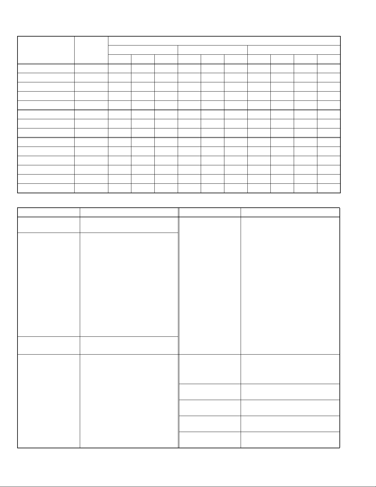
3.3.3 REPLACEMENT STEPS
1. How to remove Chip parts
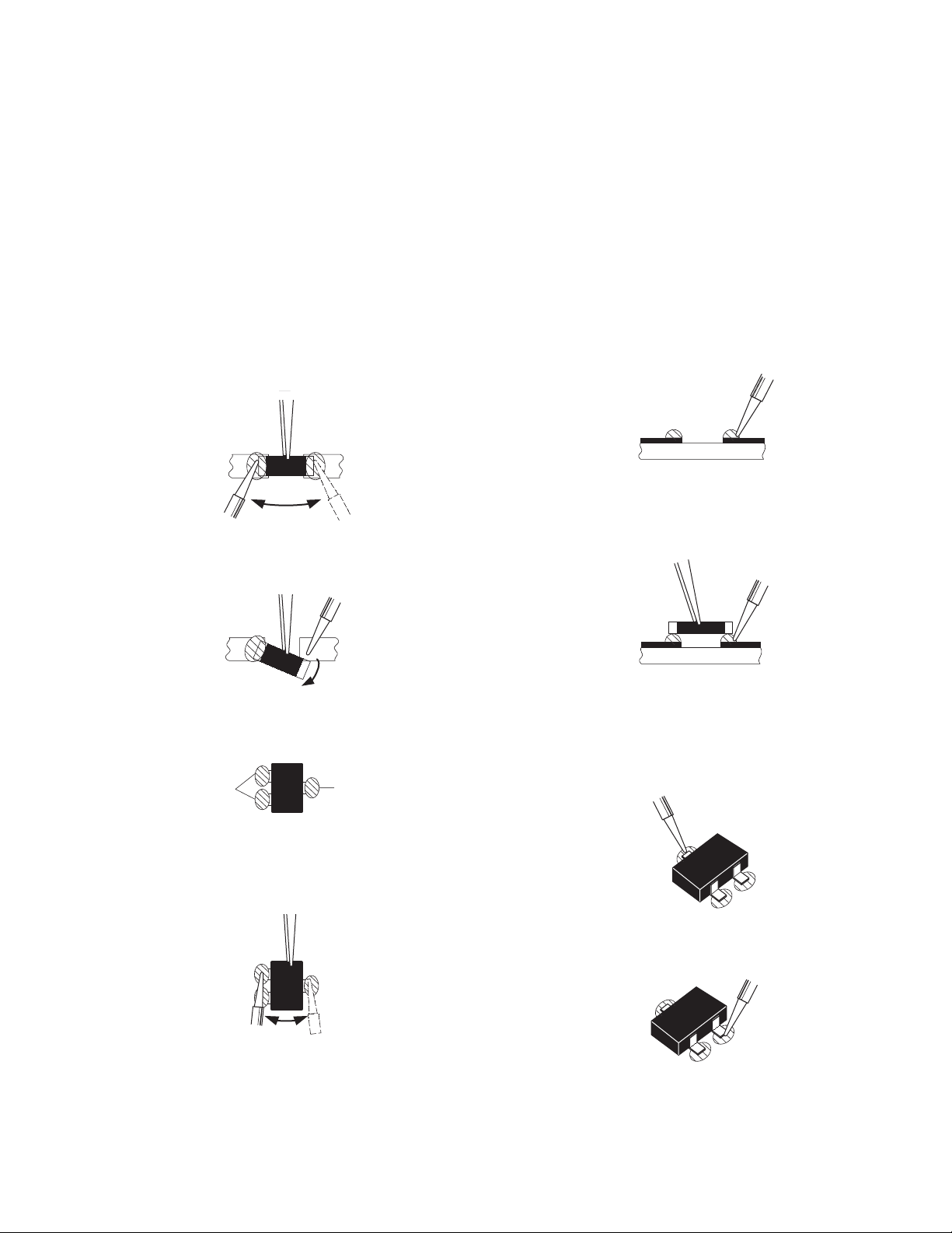
2. How to install Chip parts
[Resistors, capacitors, etc.]
(1) As shown in the figure, push the part with tweezers and
alternately melt the solder at each end.
(2) Shift with the tweezers and remove the chip part.
[Transistors, diodes, variable resistors, etc.]
(1) Apply extra solder to each lead.
SOLDER
SOLDER
[Resistors, capacitors, etc.]
(1) Apply solder to the pattern as indicated in the figure.
(2) Grasp the chip part with tweezers and place it on the
solder. Then heat and melt the solder at both ends of the
chip part.
[Transistors, diodes, variable resistors, etc.]
(1) Apply solder to the pattern as indicated in the figure.
(2) Grasp the chip part with tweezers and place it on the
solder.
(3) First solder lead A as indicated in the figure.
(2) As shown in the figure, push the part with tweezers and
alternately melt the solder at each lead. Shift and remove
the chip part.
NOTE :
After removing the part, remove remaining solder from the
pattern.
A
B
C
(4) Then solder leads B and C.
A
B
C
(No.YA207)1-11
Page 12

SECTION 4
ADJUSTMENT
4.1 ADJUSTMENT PREPARATION
(1) There are 2 ways of adjusting this TV : One is with the
REMOTE CONTROL UNIT and the other is the
conventional method using adjustment parts and
components.
(2) The adjustment using the REMOTE CONTROL UNIT is
made on the basis of the initial setting values. The
setting values which adjust the screen to the optimum
condition can be different from the initial setting
values.
(3) Make sure that connection is correctly made AC to AC
power source.
(4) Turn on the power of the TV and measuring instruments for
warming up for at least 30 minutes before starting
adjustments.
(5) If the receive or input signal is not specified, use the most
appropriate signal for adjustment.
(6) Never touch the parts (such as variable resistors,
transformers and condensers) not shown in the adjustment
items of this service adjustment.
4.2 PRESET SETTING BEFORE ADJUSTMENT
Unless otherwise specified in the adjustment items, preset the
following functions with the REMOTE CONTROL UNIT.
Item Preset value
PICTURE MODE STANDARD
CONTRAST / BRIGHT / SHARP / COLOUR / TINT Centre
WHITE BALANCE MID
DIGITAL VNR AUTO (LOW)
Super DigiPure AUTO
Colour DigiPure ON
PULL DOWN AUTO
BALANCE Centre
3D CINEMA SOUND OFF
ZOOM REGULAR
SLEEP TIMER OFF
BLUE BACK OFF
4.3 MEASURING INSTRUMENT AND FIXTURES
(1) DC voltmeter (or digital voltmeter)
(2) Oscilloscope
(3) Signal generator
(Pattern generator : PAL / SECAM / NTSC)
(4) Remote control unit
4.4 ADJUSTMENT ITEMS
CHECK ITEM
• B1 VOLTAGE check
• IF VCO check
HIGH VOLTAGE
• HIGH VOLTAGE adjustment
X-RAY PROTECTOR OPERATION SETTING
• X-RAY PROTECTOR OPERATION SETTING
HORIZONTAL FREQUENCY
• HORIZONTAL FREQUENCY adjustment
FOCUS
• FOCUS adjustment
DEFLECTION CIRCUIT
• V.POSITION adjustment
• V.SIZE adjustment
• H. POSITION adjustment
• H.SIZE adjustment
• SIDE-PIN adjustment
• TRAPEZIUM adjustment
• CORNER PIN adjustment
• V. LINEARITY adjustment
VIDEO CIRCUIT
• WHITE BALANCE adjustment
• SUB BRIGHT adjustment
• SUB CONTRAST adjustment
• SUB COLOUR adjustment
• SUB TINT adjustment
• SUB SCREEN CONTRAST adjustment
• SUB SCREEN COLOUR & TINT adjustment
VSM & SSM PRESET SETTING
• VSM & SSM PRESET setting
1-12 (No.YA207)
Page 13

4.5 ADJUSTMENT LOCATIONS
FRONT CONTROL PWB POWER SW PWB
FRONT
Y
FRONT
B
SR
SPEAKER
SL SW
WOOFER
UNIT
MAIN PWB
F
ROTATION COIL
P
RT
CN004
MICOM PWB
DIST PWB
Q X
B
CN005
MEMORY
Y
CN001
CN002
W
POWER SW
Q
POWER & DEF. PWB
CN001
CN002
J
P
POWER
& DEF. PWB
POWER
& DEF. PWB
TOP
SUB TUNER PWB
SUB TUNER
CN012
TUNER
AV SW PWB
CN008
CN009
CN007CN006
DEF OSC PWB
CN003
CN003
CN010
C
AV SW PWB
LINE FILTER PWB
POWER CORD
PW
FUSE
W
F9901
(5A)
J106
CN006 CN007
J101
J102
J103
J104
J105
F
TOP
(No.YA207)1-13
Page 14

FRONT CONTROL PWB
FRONT CONTROL PWB
MAIN PWB
DEG COIL
B
MICOM PWB
CN008
DIST PWB
CN009
CN001
CN002
CN003
CN001
CN002
J
P
DEF OSC PWB
CN010
DEF YOKE
HV
EHT
PWB
DEG
X
POWER & DEF. PWB
CN011
FBT
FRONT
FOCUS1
FOCUS2
SCREEN
AV SW PWB
CN007
VM COIL
DIST PWB
1-14 (No.YA207)
TOP
C
CRT SOCKET PWB
VM
(IC3201 9Pin side)
(IC3202 9Pin side)
TP-47G
R3224 Lead
A
TP-47R
R3225 Lead
TP-E
A
S1
5
1
1: GND (TP-E)
2: NC
3: X-RAY
4: NC
5: B1 (TP-91)
EHT PWB
TOP
EJ
R2506
X-RAY ADJ
R2510
EHT ADJ
CN011
Page 15

4.6 TOOL OF SERVICE MODE OPERATION
Operate the SERVICE MODE with the REMOTE CONTROL UNIT.
4.6.1 SERVICE MODE ITEMS
With the SERVICE MODE, various adjustment can be made, and they are broadly classified in the following items of settings.
1.IF This mode adjusts the IF circuit.
2.V/C This mode adjusts the VIDEO circuit
3.AUDIO This mode adjusts the AUDIO circuit. [Do no adjust]
4.DEF This mode adjusts the DEFLECTION circuit.
5.VSM & SSM PRESET This mode sets the VSM (Video Status Memory) and SSM (Sound Status Memory) data.
2
6.STATUS This mode shows the I
C memory data software version and information. [Do no adjust]
7.3DNR This mode adjusts the 3DNR (three-Dimension Noise Reduction) circuit. [Do no adjust]
8.IP This mode adjusts the DIST circuit. [Do no adjust]
9.SHIPPING This mode initialize the data for factory shipment. [Do no adjust]
2
0.BUS FREE This mode stops the all I
C bus communication. [Do no adjust]
4.6.2 BASIC OPERATION IN SERVICE MODE
4.6.2.1 HOW TO ENTER THE SERVICE MODE
Press the [DISPLAY] key and [MUTING] key of the REMOTE
CONTROL UNIT simultaneously. Then SERVICE MODE screen
will be displayed as shown figure.
NOTE:
Before entering the SERVICE MODE, confirm that the setting
of PIP/TV/ DVD switch is at the "TV" side.
4.6.2.2 SELECTION OF SUB MENU SCREEN
Press one of the CHANNEL number key with the remote control
unit, and select the SUB MENU SCREEN from SERVICE
MODE.
4.6.2.3 SETTING METHOD
1.IF
[1. VCO] : It must not adjust without signal
SERVICE MENU
1. IF
3. AUDIO
5. VSM & SSM PRESET
7. 3DNR
9. SHIPPING(OFF)
2. V/C
4. DEF
6. STATUS
8. IP
0. BUS FREE
(1) [1] key
Select 1.IF.
(2) [1] key
Select 1.VCO(CW).
Check the arrow position between the ABOVE REF. and
BELOW REF.
1-9 : SELECT i : EXIT
(3) [DISPLAY] key
Return to the SERVICE MODE main manu screen.
Fig.1
2.V/C, 4.DEF and 5.VSM & SSM PRESET.
(1) [2], [4] and [5]key
MUTING
ZOOM
FUNCTION /
DISPLAY
123
456
789
RETURN+
0
SUB-P
TV/VIDEO MENU
OK
DISPLAY
SUB-P
CHANNEL VOLUME
DVDPIP T V
PIP/TV/DVD
switch
CINEMA
MENU
FUNCTION /
BACK
3.AUDIO, 6.STATUS, 7.3DNR, 8.IP, 9. SHIPPING(OFF) and
Select one from 2.V/C, 4.DEF, 5.VSM & SSM PRESET.
(2) [FUNCTION /] key
Select setting items.
(3) [FUNCTION /] key
Set the setting values of the setting items.
(4) [MENU] key
Memorize the setting value.
(Before storing the setting values in memory, do not
press the CH, TV, POWER ON / OFF key. if you do, the
values will not be stored in memory.)
(5) [DISPLAY] key
Return to the SERVICE MODE main manu screen.
0. BUS FREE.
SOUND
MODE
STROBE
CINEMA
SURROUND
F. T /L
BASS ZOOM
?
TOP MENU
It is not requirement to adjustment.
4.6.2.4 MEMORIZE THE ADJUSTMENT DATA
When adjustment is completed, press the [MENU] key to
memorize the adjustment value. If not to do it, adjustment data is
not memorized to the memory IC. And if exit the adjustment
mode before memorize the data, the adjustment value which you
change is canceled.
Fig.2
4.6.2.5 RELEASE OF SERVICE MENU
After completing the setting, return to the SERVICE MENU, then
again press the [DISPLAY] key.
(No.YA207)1-15
Page 16

4.6.3 SERVICE MODE SETTING
1. IF
The setting for VCO is described in the IF VCO page of
ADJUSTMENT PROCEDURE.
2. V/C
The setting for video data adjustment.
COLOUR SYSTEM
V / C PAL
1.CUT_OF_R 130
Setting value
Setting item
- / + : STORE i : EXIT
MENU
#################
< COLOUR SYSTEM >
PAL : PAL
SECAM : SECAM
N3 : NTSC3.58
N4 : NTSC4.43
4. DEF
The setting for defrection data adjustment.
ZOOM MODE
DEF FULL 1125i
1. FREE-RUN 0
( 93)
SCAN MODE
Setting value
Offset value
5. VSM & SSM PRESET
The setting for video status memory data and sound status
memory data adjustment.
Video status/Sound status
VSM & SSM PRESET BRIGHT
1. CONT 16
Setting value
Setting item
- / + : STORE i : EXIT
MENU
- / + : STORE i : EXIT
MENU
Setting item
< ZOOM MODE >
FULL : This means that the screen mode is REGULAR.
NOTE:
Display only FULL. Adjustment in other aspect mode are
not required in SERVICE MODE.
< SCAN MODE >
SINGLE SCREEN mode
900i : 625i, 625p
1125i : 525i, 525p, 1125i (fv: 60Hz)
1350i : 1125i (fv: 50Hz)
602p : 625i (Text screen)
MULTI SCREEN mode
900i : 9 (index) screen, 5 screen(main:625i,625p)
1125i : 5 (index) screen(main:525i,525p), 2 (twin) screen (others)
1350i : 2 screen(main&sub:625i,625p)
< OFFSET VALUE >
The value adjusted by 900i is displayed.
1-16 (No.YA207)
Page 17

4.7 SERVICE MODE FLOW CHART
SUB MENU SCREEN
1. VCO
2. ATT ON / OFF
1-2: SELECT i : EXIT
VCO(CW) **.**MHz
MAIN SUB
1. CUT_OF R
2. CUT_OF G
3. CUT_OF B
4. DRIVE_R
5. DRIVE_G
6. DRIVE_B
7. BRIGHT
8. CONT
9. COLOUR
10. HUE
11. TWN_CNT
12. TWN_COL
13. TWN_TNT
14. BY_GAIN
15. RY_ANGL
1. ERROR LIMIT
24. BBE ON120
1. FREE-RUN
2. V-SHIFT
3. V-SIZE
4. H-CENT
5. H-SIZE
6. TRAPEZ
7. EW-PIN
8. COR-UP
9. COR-LOW
10. V.S-CR
11. V-LIN
Do not adjust
Do not adjust
TOO HIGH
ABOVE REF.
JUST REF.
BELOW REF.
TOO LOW
1.CUT_OF_R 130
- / + : STORE i : EXIT
1. ERROR LIMIT 0100
ERROR LIMIT = D7FF
C_AD_BITS = 00000000
- / + : STORE i : EXIT
1. FREE-RUN 0
- / + : STORE i : EXIT
0. BUS FREE
1.IF
IF SERVICE MENU
i : EXIT
2. V/C
V /C N3
MENU
################
3. AUDIO
AUDIO
MENU
4. DEF
DEF FULL 1125i
MENU
MAIN MENU SCREEN
SERVICE MENU
1. IF
3. AUDIO
5. VSM & SSM PRESET
7. 3DNR
9. SHIPPING(OFF)
1-9 : SELECT i : EXIT
(93)
2. V/C
4. DEF
6. STATUS
8. IP
0. BUS FREE
1. CONT
2. BRIGHT
3. SHARP
4. COLOUR
5. TINT
Do not adjust
Do not adjust
Do not adjust
Do not adjust
5. VSM & SSM PRESET
VSM & SSM PRESET BRIGHT
1. CONT 16
- / + : STORE i : EXIT
MENU
1. WDR R
2. WDR G
3. WDR B
6. 120Hz
7. 500Hz
8. 1.5KHz
9. 5KHz
10. 10KHz
11. EFFECT
6. STATUS
STATUS
1. SOFT
- / + : STORE i : EXIT
MENU
7. 3DNR
3DNR 3DYC
1. YNR LIM 0000
- / + : STORE i : EXIT
MENU
8. IP
IP 900i
1. ASLGAIN 0000
- / + : STORE i : EXIT
MENU
9. SHIPPING
SHIPPING (OFF)
SHIPPING (ON)
PICTURE MODE
BRIGHT
STD
SOFT
WHITE BALANCE
COOL
MID
WARM
SOUND STATUS
DYNAMIC
MUSIC
NEWS
USER
1.SOFT
2.TELETEXT
3.ASPECT
4.IC
1. YNR LIM
90. HGCON21
1. ASVGAIN
70. BVMCORINGON
I2C BUS FREE
(No.YA207)1-17
Page 18

4.8 INITIAL SETTING VALUE OF SERVICE MODE
(1) Adjustment of the SERVICE MODE is made on the basis of the initial setting values. However, the new setting values which
displays on the screen in its optimum condition may differ from the initial setting value.
(2) Do not change the initial setting values of the items not listed in "ADJUSTMENT PROCEDURE".
(3) "---" is impossible to adjust or not requirement to adjustment.
4.8.1 [2. V/C]
Setting item
1.CUT OF R 000~255 140 140 140 140 140 140 140 140
2.CUT OF G 000~255 140 140 140 140 140 140 140 140
3.CUT OF B 000~255 140 140 140 140 140 140 140 140
4.DRIVE R 000~255 064 064 064 064 064 064 064 064
5.DRIVE G 000~255 064 064 064 064 064 064 064 064
6.DRIVE B 000~255 064 064 064 064 064 064 064 064
7.BRIGHT 000~255 130 130 130 130 130 130 130 130
8.CONT 000~127 070 070 070 070 070 070 070 070
9.COLOUR 000~127 064 055 064 000 000 000 000 000
10.HUE 000~127 000 000 063 000 000 000 000 000
11.TWN CNT 000~015 009 009 009 009 009 009 009 009
12.TWN COL 000~015 009 009 009 000 000 000 000 000
13.TWN TNT 000~063 000 000 035 000 000 000 001 000
14.BY GAIN 000~063 043 043 043 000 043 043 043 000
15.RY ANGLE 000~015 005 005 006 000 005 005 006 000
Variable
range
RF External (Composite / S-video)
PAL SECAM NTSC3.58 NTSC4.43 PAL SECAM NTSC3.58 NTSC4.43
Setting value
Setting item
1.CUT OF R 000~255 140 140 000 000 000 000
2.CUT OF G 000~255 140 140 000 000 000 000
3.CUT OF B 000~255 140 140 000 000 000 000
4.DRIVE R 000~255 064 064 000 000 000 000
5.DRIVE G 000~255 064 064 000 000 000 000
6.DRIVE B 000~255 064 064 000 000 000 000
7.BRIGHT 000~255 130 130 000 000 -03 -03
8.CONT 000~127 070 070 000 000 000 000
9.COLOUR -61~066 -10 -10 -10 -10 000 000
10.HUE 000~127 065 065 000 001 000 002
11.TWN CNT 000~015 000 000 --- --- 000 000
12.TWN COL -02~013 000 000 000 000 000 000
13.TWN TNT 000~063 000 000 000 001 000 000
14.BY GAIN 000~063 000 000 000 000 000 000
15.RY ANGLE 000~015 000 000 000 000 000 000
4.8.2 [3. AUDIO]
Setting item
1.ERROR LIM 0000~FFF0 0100
2.A2 ID THR 0000~00FF 0014
3.Q-PEAK ----- -----
4.SOUND LEV 0000~FFF0 FFFF
Variable
range
Variable
range
625i 525i 625p 525p 1125i / 50Hz 1125i / 60Hz
Setting value
Setting value
External (Component)
1-18 (No.YA207)
Page 19

Setting item
5.VIRT_MODE ----
6.VIRT_SPAT 0000~007F 000F 003A --- --- --- --- --- ---
7.VIRTUAL EFF 0000~007F 000C 0034 --- --- --- --- --- ---
8.SPATIAL EF 0000~007F --- --- 003F --- --- --- --- ---
9.MB_STR 0000~007F --- --- 0000 0000 0025 0000 0035 0030
10.MB_HMC 0000~007F --- --- 0000 0000 0000 0000 0000 0000
11.MB_HP 0002~001E --- --- 0000 0000 0009 0000 0009 0009
12.MB_LP 0005~001E --- --- 0000 0000 000A 0000 000A 000A
13.MB_LIMIT 0000~00FF --- --- 0000 0000 00E5 0000 0000 00F6
14.SUBW_LEV 0000~00FF --- --- 0000 0000 0000 0000 0000 0000
15.SUBW_FREQ 0005~0028 --- --- 0000 0000 000A 0000 000A 000A
16.SUBW_CHAR 0000~0003 --- --- 0000 0000 0001 0000 0001 0001
17.SUBW_HP 0000~0002 --- --- 0000 0000 0002 0000 0002 0002
18.VOL_CLP_M 0000~0003 --- --- 0003 0003 0003 0003 0003 0003
Variable
range
3D CINEMA SURROUND SUPER BASS
LOW HIGH MONO OFF LOW MID HIGH OFF
3D PANORAMA 3D PANORAMA
--- --- --- --- --- ---
Setting value
Setting item
19.LIPSYNC ON / OFF OFF
20.DELAY TIME
21.BBE LEVEL 0000~00FF 00FC
22.BBE ON5K 0000~00FF 00FD
23.BBE ON10K 0000~00FF 00FA
24.BBE ON120 0000~00FF 00FA
Variable
range
32ms~128ms
Setting value
32ms
(No.YA207)1-19
Page 20

4.8.3 [4. DEF]
Setting value
Setting item
1.FREE-RUN -55~200 90 0 0 0 0 0
2.V-SHIFT -18~45 22 0 0 0 0 0
3.V-SIZE -40~87 57 0 0 -3 -28 -28
4.H-CENT -18~237 50 0 0 0 0 0
5.H-SIZE -31~32 35 0 0 0 0 0
6.TRAPEZ -30~33 32 0 0 0 0 0
7.EW-PIN -21~42 20 0 0 0 0 0
8.COR-UP -9~6700000
9.COR-LOW -9~6 7 0 0 0 0 0
10.V.S-CR -24~39 50 0 0 0 0 0
11.V-LIN -40~23 41 1 3 0 0 0
4.8.4 [5. VSM & SSM PRESET]
Setting item
1.CONT -16~16 16 5 -8 --- --- --- --- --- --- ---
2.BRIGHT -16~16 0 0 0 --- --- --- --- --- --- ---
3.SHARP -16~16 0 0 -2 --- --- --- --- --- --- ---
4.COLOUR -16~16 0 0 -2 --- --- --- --- --- --- ---
5.TINT -16~16 0 0 0 --- --- --- --- --- --- ---
1.WDR R -64~63 --- --- --- 0 0 19 --- --- --- ---
2.WDR G -64~63 --- --- --- 0 0 0 --- --- --- ---
3.WDR B -64~63 --- --- --- 12 0 0 --- --- --- ---
6.120Hz -10~10 --- --- --- --- --- --- 4 3 -7 0
7.500Hz -10~10 --- --- --- --- --- --- 5 2 1 0
8.1.5KHz -10~10 --- --- --- --- --- --- -2 0 5 0
9.5KHz -10~10 --- --- --- --- --- --- 1 1 2 0
10.10KHz -10~10 --- --- --- --- --- --- 3 3 -6 0
11.EFFECT -128~127 --- --- --- --- --- --- 0 0 -61 0
Variable
range
Variable
range
REGULAR 16:9
900i 1125i 1350i 602p 1125i 1350i
PICTURE MODE WHITE BALANCE SOUND STATUS
BRIGHT
STD SOFT COOL MID WARM
ASPECT (ZOOM)
Setting value
DYNAMIC
MUSIC NEWS USER
1-20 (No.YA207)
Page 21

4.8.5 [7.3DNR] (*All the value are fixed values.)
Setting value
Setting item
1.YNR LIM 0000~0007 0003 0003 0003 0003 0003 0003 0003 0003 0003 0003
2.YNR K 0000~0003 0002 0002 0002 0002 0002 0002 0002 0002 0002 0002
3.YNR GAIN 0000~0007 0001 0001 0001 0001 0001 0001 0001 0001 0001 0001
4.CNR LIM 0000~0007 0003 0003 0003 0003 0003 0003 0003 0003 0003 0003
5.CNR K 0000~0003 0002 0002 0002 0002 0002 0002 0002 0002 0002 0002
6.CNR GAIN 0000~0007 0001 0001 0001 0001 0001 0001 0001 0001 0001 0001
7.LTI GAIN 0000~0003 0000 0001 0000 0000 0000 0001 0000 0000 0000 0000
8.LTI SLICE 0000~0003 0000 0000 0000 0000 0000 0000 0000 0000 0001 0000
9.CTI GAIN 0000~0003 0002 0003 0003 0002 0002 0003 0003 0002 0002 0002
10.CTI SLICE 0000~0003 0000 0000 0000 0000 0000 0000 0000 0000 0001 0000
11.BRIGHTNES 0000~000F 0003 0003 0003 0003 0001 0001 0001 0001 0001 0001
12.CONTRAST 0000~00FF 0010 0010 0010 0010 0010 0010 0010 0010 0014 0014
13.AC M SLP 0000~0003 0003 0003 0003 0003 0003 0003 0003 0003 0003 0003
14.AC S SLP 0000~0003 0003 0003 0001 0003 0003 0003 0001 0003 0003 0003
15.AY M SLP 0000~0003 0002 0002 0002 0002 0002 0002 0002 0002 0002 0002
16.AY S SLP 0000~0003 0002 0002 0001 0002 0002 0002 0001 0002 0002 0002
17.AC M E SE 0000~0003 0002 0002 0003 0002 0002 0002 0003 0002 0002 0002
18.AC M F SE 0000~0003 0002 0002 0003 0002 0002 0002 0003 0002 0002 0002
19.AC S E SE 0000~0003 0000 0000 0002 0000 0000 0000 0002 0000 0000 0000
20.AC S F SE 0000~0003 0000 0000 0002 0000 0000 0000 0002 0000 0000 0000
21.AY M E SE 0000~0003 0002 0002 0003 0002 0002 0002 0003 0002 0002 0002
22.AY M F SE 0000~0003 0002 0002 0003 0002 0002 0002 0003 0002 0002 0002
23.AY S E SE 0000~0003 0000 0000 0001 0000 0000 0000 0001 0000 0000 0000
24.AY S F SE 0000~0003 0000 0000 0002 0000 0000 0000 0002 0000 0000 0000
25.BC M SLP 0000~0003 0003 0003 0003 0003 0003 0003 0003 0003 0003 0003
26.BC S SLP 0000~0003 0003 0003 0002 0003 0003 0003 0002 0003 0003 0003
27.BY M SLP 0000~0003 0000 0000 0003 0000 0000 0000 0003 0000 0000 0000
28.BY S SLP 0000~0003 0000 0000 0002 0000 0000 0000 0002 0000 0000 0000
29.BC M E SE 0000~0003 0002 0002 0003 0002 0002 0002 0003 0002 0002 0002
30.BC M F SE 0000~0003 0002 0002 0002 0002 0002 0002 0002 0002 0002 0002
31.BC S E SE 0000~0003 0000 0000 0002 0000 0000 0000 0002 0000 0000 0000
32.BC S F SE 0000~0003 0000 0000 0002 0000 0000 0000 0002 0000 0000 0000
33.BY M E SE 0000~0003 0000 0000 0002 0000 0000 0000 0002 0000 0000 0000
34.BY M F SE 0000~0003 0000 0000 0003 0000 0000 0000 0003 0000 0000 0000
35.BY S E SE 0000~0003 0000 0000 0002 0000 0000 0000 0002 0000 0000 0000
36.BY S F SE 0000~0003 0000 0000 0002 0000 0000 0000 0002 0000 0000 0000
37.BC M UP 0000~0001 0001 0001 0001 0001 0001 0001 0001 0001 0001 0001
38.C E CMP 0000~0007 0004 0004 0005 0004 0004 0004 0005 0004 0004 0004
39.C S CMP 0000~000F 0008 0008 0001 0008 0008 0008 0001 0008 0008 0008
40.F1HER 0000~0003 0001 0001 0001 0001 0001 0001 0001 0001 0001 0001
41.F1VER 0000~0003 0001 0001 0001 0001 0001 0001 0001 0001 0001 0001
42.MREF 0000~000F 0005 0005 0002 0005 0005 0005 0002 0005 0005 0005
43.CDEYE 0000~0003 0001 0001 0002 0001 0001 0001 0002 0001 0001 0001
44.YDEYE 0000~0003 0001 0001 0000 0001 0001 0001 0000 0001 0001 0001
45.MDS 0000~0001 0000 0000 0000 0000 0000 0000 0000 0000 0000 0000
46.MDMPL 0000~0001 0000 0000 0000 0000 0000 0000 0000 0000 0000 0000
47.MDMBL 0000~0001 0000 0000 0000 0000 0000 0000 0000 0000 0000 0000
48.3D STD 0000~0001 0000 0000 0000 0000 0000 0000 0000 0000 0000 0000
Variable
range
PAL SECAM
RF
NTSC3.58 NTSC4.43
(Composite / S-VIDEO)
PAL SECAM
External
NTSC3.58 NTSC4.43
External
(Component)
625i 525i
(No.YA207)1-21
Page 22

Setting value
Setting item
49.2ASS 0000~0001 0001 0001 0001 0001 0001 0001 0001 0001 0001 0001
50.2ASEL 0000~0001 0000 0000 0000 0000 0000 0000 0000 0000 0000 0000
51.2ALEV 0000~0007 0001 0001 0001 0001 0001 0001 0001 0001 0001 0001
52.2ASSCM 0000~0003 0002 0002 0002 0002 0002 0002 0002 0002 0002 0002
53.CROSS 0000~0001 0000 0000 0001 0000 0000 0000 0001 0000 0000 0000
54.CHLPF 0000~0001 0000 0000 0000 0000 0000 0000 0000 0000 0000 0000
55.YDCLOFF 0000~0001 0001 0001 0000 0001 0001 0001 0000 0001 0001 0001
56.YDNRW 0000~0001 0000 0000 0000 0000 0000 0000 0000 0000 0000 0000
57.CDNRW 0000~0001 0000 0000 0001 0000 0000 0000 0001 0000 0000 0000
58.YDCMP 0000~000F 0008 0008 0000 0008 0008 0008 0000 0008 0008 0008
59.HDAMP1 0000~0007 0003 0003 0003 0003 0000 0000 0000 0000 0000 0000
60.HDGAIN1 0000~001F 0008 0008 0008 0008 000D 000D 000D 000D 0010 0010
61.HDAMP2 0000~0007 0004 0004 0004 0004 0003 0003 0003 0003 0003 0003
62.HDGAIN2 0000~001F 0003 0003 0003 0003 0007 0007 0007 0007 001C 001C
63.HDAMP3 0000~0007 0004 0004 0004 0004 0004 0004 0004 0004 0004 0004
64.HDGAIN3 0000~001F 0004 0004 0004 0004 0003 0003 0003 0003 000C 000C
65.SHCTRL 0000~003F 003F 003F 003F 003F 003F 003F 003F 003F 003F 003F
66.MUTE 0000~0001 0000 0000 0000 0000 0000 0000 0000 0000 0000 0000
67.CMUTE 0000~0001 0000 0000 0000 0000 0000 0000 0000 0000 0000 0000
68.(Not used) --- --- --- --- --- --- --- --- --- --- ---
69.(Not used) --- --- --- --- --- --- --- --- --- --- ---
70.(Not used) --- --- --- --- --- --- --- --- --- --- ---
71.BCFOFF 0000~0001 0001 0001 0001 0001 0001 0001 0001 0001 0001 0001
72.CGAIN 0000~0007 0007 0007 0007 0007 0007 0007 0007 0007 0007 0007
73.EN NOISEH S 0000~0007 0004 0004 0004 0004 0004 0004 0004 0004 0004 0004
74.EN NOISEH W 0000~0007 0004 0004 0004 0004 0004 0004 0004 0004 0004 0004
75.EN NOISEV S 0000~0007 0000 0000 0000 0000 0000 0000 0000 0000 0000 0000
76.EN NOISEV W 0000~0003 0001 0001 0001 0001 0001 0001 0001 0001 0001 0001
77.HDPH 0000~000F 0000 0000 0000 0000 0000 0000 0000 0000 0000 0000
78.VDPH 0000~000F 0000 0000 0000 0000 0000 0000 0000 0000 0000 0000
79.VPHS 0000~0007 0000 0000 0000 0000 0000 0000 0000 0000 0000 0000
80.EN PIXH S 0000~000F 0000 0000 0000 0000 0000 0000 0000 0000 0000 0000
81.EN PIXH W 0000~000F 0000 0000 0000 0000 0000 0000 0000 0000 0000 0000
82.EN PIXV S 0000~000F 0000 0000 0000 0000 0000 0000 0000 0000 0000 0000
83.EN PIXV A 0000~0001 0000 0000 0000 0000 0000 0000 0000 0000 0000 0000
84.HBLK S 0000~000F 0000 0000 0000 0000 0000 0000 0000 0000 0000 0000
85.HBLK W 0000~000F 0000 0000 0000 0000 0000 0000 0000 0000 0000 0000
86.FHST S 0000~000F 0000 0000 0000 0000 0000 0000 0000 0000 0000 0000
87.FVST S 0000~000F 0000 0000 0000 0000 0000 0000 0000 0000 0000 0000
88.EXTCLP 0000~000F 0009 0009 0009 0009 0009 0009 0009 0009 0009 0009
89.HGCON12 0000~000F 0004 0004 0004 0004 0003 0003 0003 0003 000C 000C
90.HGCON21 0000~000F 000A 000A 000A 000A 000E 000E 000E 000E 000E 000E
Variable
range
PAL SECAM
RF
NTSC3.58 NTSC4.43
(Composite / S-VIDEO)
PAL SECAM
External
NTSC3.58 NTSC4.43
External
(Component)
625i 525i
1-22 (No.YA207)
Page 23

4.8.6 [8. IP] (All the value are fixed vaiues.)
Setting value
Single screen / PIP (Main screen)
Setting item
1. ASLGAIN 0000~0063 0024 0024 0024 0024 0024 0014 0027
2. ASLVHGAIN 0000~0063 0008 0008 0008 0008 0008 0000 0019
3. ASLHGAIN 0000~0063 0021 0030 0038 0038 0038 0026 0021
4. ASLVPEAKFREQ 0000~0003 0001 0001 0001 0001 0001 0001 0001
5. ASLHPEAKFREQ 0000~0007 0001 0001 0001 0001 0001 0001 0001
6. ASLEDGECTRL 0000~0063 0037 0025 0037 0030 0025 0018 0015
7. ASLEDGECTRLON 0000~0001 0001 0001 0001 0001 0001 0001 0001
8. ASLCORINGON 0000~0001 0001 0001 0001 0001 0001 0001 0001
9. ASLENHACEON 0000~0001 0001 0001 0001 0001 0001 0001 0001
10. ASVPEAKFREQ 0000~0003 0002 0002 0002 0002 0002 0002 0002
11. ASHPEAKFREQ 0000~0007 0004 0004 0004 0004 0004 0004 0004
12. ASYLCONTROL 0000~0063 0032 0028 0004 0005 0004 0004 0008
13. ASYLCTRLON 0000~0001 0001 0001 0001 0001 0001 0001 0001
14. ASYHCONTROL 0000~0063 0063 0063 0031 0063 0063 0063 0063
15. ASYHCTRLON 0000~0001 0001 0001 0001 0001 0001 0001 0001
16. ASCCONTROL 0000~0063 0007 0007 0016 0016 0016 0023 0032
17. ASENHANCEON 0000~0001 0001 0001 0001 0001 0001 0001 0001
18. ASPMBALANCE 0000~0063 0001 0005 0006 0006 0006 0006 0018
19. ASPMBLNCEON 0000~0001 0001 0001 0001 0001 0001 0001 0001
20. ASLIMIT 0000~0063 0051 0051 0051 0051 0051 0032 0016
21. ASLIMITON 0000~0001 0001 0001 0001 0001 0001 0001 0001
22. ASCORINGON 0000~0001 0001 0001 0001 0001 0001 0001 0001
23. APBGAIN 0000~0063 0026 0026 0026 0026 0026 0026 0026
24. APBPEAKFREQ 0000~0007 0002 0002 0002 0002 0002 0002 0003
25. APBCORING 0000~0063 0009 0009 0009 0009 0009 0009 0009
26. APBCORINGON 0000~0001 0001 0001 0001 0001 0001 0001 0001
27. APRGAIN 0000~0063 0026 0026 0026 0026 0026 0026 0026
28. APRPEAKFREQ 0000~0007 0002 0002 0002 0002 0002 0002 0003
29. APRCORING 0000~0063 0009 0009 0009 0009 0009 0009 0009
30. APRCORINGON 0000~0001 0001 0001 0001 0001 0001 0001 0001
31. AVMPEAKFREQ 0000~0007 0002 0003 0003 0003 0003 0003 0002
32. AVMLIMITON 0000~0001 0001 0001 0001 0001 0001 0001 0001
33. AVMHCONTROL 0000~0063 0032 0032 0032 0032 0032 0026 0010
34. AVMHCTRLON 0000~0001 0000 0000 0000 0000 0000 0001 0000
35. AVMCORINGON 0000~0001 0001 0001 0001 0001 0001 0001 0001
Variable
range
RF
625i 525i 625i 525i 625i / 525i 625p / 525p
External
(Composite / S)
External
(Component)
1125i
(only Single screen)
(No.YA207)1-23
Page 24

Setting value
Setting item
1. ASLGAIN 0000~0063 0024 0024 0024 0024 0014 0024
2. ASLVHGAIN 0000~0063 0008 0008 0008 0008 0000 0008
3. ASLHGAIN 0000~0063 0021 0026 0026 0026 0018 0026
4. ASLVPEAKFREQ 0000~0003 0001 0001 0001 0001 0001 0001
5. ASLHPEAKFREQ 0000~0007 0001 0001 0001 0001 0001 0001
6. ASLEDGECTRL 0000~0063 0037 0037 0037 0037 0018 0037
7. ASLEDGECTRLON 0000~0001 0001 0001 0001 0001 0001 0001
8. ASLCORINGON 0000~0001 0001 0001 0001 0001 0001 0001
9. ASLENHACEON 0000~0001 0001 0001 0001 0001 0001 0001
10. ASVPEAKFREQ 0000~0003 0002 0002 0002 0002 0003 0002
11. ASHPEAKFREQ 0000~0007 0004 0004 0004 0004 0004 0004
12. ASYLCONTROL 0000~0063 0005 0005 0005 0005 0005 0005
13. ASYLCTRLON 0000~0001 0001 0001 0001 0001 0001 0001
14. ASYHCONTROL 0000~0063 0063 0063 0063 0063 0063 0063
15. ASYHCTRLON 0000~0001 0001 0001 0001 0001 0001 0001
16. ASCCONTROL 0000~0063 0007 0016 0016 0007 0023 0007
17. ASENHANCEON 0000~0001 0001 0001 0001 0001 0001 0001
18. ASPMBALANCE 0000~0063 0001 0006 0006 0006 0006 0010
19. ASPMBLNCEON 0000~0001 0001 0001 0001 0001 0001 0001
20. ASLIMIT 0000~0063 0051 0051 0051 0051 0032 0051
21. ASLIMITON 0000~0001 0001 0001 0001 0001 0001 0001
22. ASCORINGON 0000~0001 0001 0001 0001 0001 0001 0001
23. APBGAIN 0000~0063 0026 0026 0026 0026 0026 0026
24. APBPEAKFREQ 0000~0007 0002 0002 0002 0002 0002 0002
25. APBCORING 0000~0063 0009 0009 0009 0009 0009 0009
26. APBCORINGON 0000~0001 0001 0001 0001 0001 0001 0001
27. APRGAIN 0000~0063 0026 0026 0026 0026 0026 0026
28. APRPEAKFREQ 0000~0007 0002 0002 0002 0002 0002 0002
29. APRCORING 0000~0063 0009 0009 0009 0009 0009 0009
30. APRCORINGON 0000~0001 0001 0001 0001 0001 0001 0001
31. AVMPEAKFREQ 0000~0007 0003 0003 0003 0003 0003 0003
32. AVMLIMITON 0000~0001 0001 0001 0001 0001 0001 0001
33. AVMHCONTROL 0000~0063 0032 0032 0032 0032 0032 0032
34. AVMHCTRLON 0000~0001 0000 0000 0000 0000 0001 0000
35. AVMCORINGON 0000~0001 0001 0001 0001 0001 0001 0001
Variable
range
Text 2 screen / Multi 2 screen / Multi 5 screen (Main screen)
External
(Composite / S)
625i / 525i 625i 525i 625i / 525i 625p / 525p
External
(Component)
9 screenRF
1-24 (No.YA207)
Page 25

Setting value
PIP / Twin screen : Main screen input=625i / 525i
Setting item
36. BSLVGAIN 0000~0063 0024 0024 0024 0024 0024 0024 0024
37. BSLVHGAIN 0000~0063 0008 0008 0008 0008 0008 0008 0008
38. BSLHGAIN 0000~0063 0021 0021 0021 0026 0026 0026 0026
39. BSLVPEAKFREQ 0000~0003 0001 0001 0001 0001 0001 0001 0001
40. BSLHPEAKFREQ 0000~0007 0001 0001 0001 0001 0001 0001 0001
41. BSLEDGECTRL 0000~0063 0037 0037 0037 0037 0037 0037 0037
42. BSLEDGECTRLON 0000~0001 0001 0001 0001 0001 0001 0001 0001
43. BSLCORINGON 0000~0001 0001 0001 0001 0001 0001 0001 0001
44. BSLENHACEON 0000~0001 0001 0001 0001 0001 0001 0001 0001
45. BSVPEAKFREQ 0000~0003 0002 0002 0002 0002 0002 0002 0002
46. BSHPEAKFREQ 0000~0007 0004 0004 0004 0004 0004 0004 0004
47. BSYLCONTROL 0000~0063 0032 0032 0032 0035 0035 0035 0035
48. BSYLCTRLON 0000~0001 0001 0001 0001 0001 0001 0001 0001
49. BSYHCONTROL 0000~0063 0063 0063 0063 0063 0063 0063 0063
50. BSYHCTRLON 0000~0001 0001 0001 0001 0001 0001 0001 0001
51. BSCCONTROL 0000~0063 0007 0007 0007 0016 0016 0007 0007
52. BSENHANCEON 0000~0001 0001 0001 0001 0001 0001 0001 0001
53. BSPMBALANCE 0000~0063 0001 0001 0001 0006 0006 0006 0006
54. BSPMBLNCEON 0000~0001 0001 0001 0001 0001 0001 0001 0001
55. BSLIMIT 0000~0063 0051 0051 0051 0051 0051 0051 0051
56. BSLIMITON 0000~0001 0001 0001 0001 0001 0001 0001 0001
57. BSCORINGON 0000~0001 0001 0001 0001 0001 0001 0001 0001
58. BPBGAIN 0000~0063 0048 0026 0026 0026 0026 0026 0026
59. BPBPEAKFREQ 0000~0007 0007 0002 0002 0002 0002 0002 0002
60. BPBCORING 0000~0063 0008 0009 0009 0009 0009 0009 0009
61. BPBCORINGON 0000~0001 0001 0001 0001 0001 0001 0001 0001
62. BPRGAIN 0000~0063 0048 0026 0026 0026 0026 0026 0026
63. BPRPEAKFREQ 0000~0007 0007 0002 0002 0002 0002 0002 0002
64. BPRCORING 0000~0063 0008 0009 0009 0009 0009 0009 0009
65. BPRCORINGON 0000~0001 0001 0001 0001 0001 0001 0001 0001
66. BVMPEAKFREQ 0000~0007 0003 0003 0003 0003 0003 0003 0003
67. BVMLIMITON 0000~0001 0001 0001 0001 0001 0001 0001 0001
68. BVMHCONTROL 0000~0063 0032 0032 0032 0032 0032 0032 0032
69. BVMHCTRLON 0000~0001 0000 0000 0000 0000 0000 0000 0000
70. BVMCORINGON 0000~0001 0001 0001 0001 0001 0001 0001 0001
Variable
range
Single
screen
RF
625i 525i 625i 525i 625i 525i
Sub screen
External
(Composite / S)
External
(Component)
(No.YA207)1-25
Page 26

Setting value
PIP / Twin screen : Main screen input=625p / 525p
Setting item Variable range
RF
625i 525i 625i 525i 625i 525i
36. BSLVGAIN 0000~0063 0024 0024 0024 0024 0024 0024 0024
37. BSLVHGAIN 0000~0063 0008 0008 0008 0008 0008 0008 0008
38. BSLHGAIN 0000~0063 0021 0021 0026 0026 0026 0026 0026
39. BSLVPEAKFREQ 0000~0003 0001 0001 0001 0001 0001 0001 0001
40. BSLHPEAKFREQ 0000~0007 0001 0001 0001 0001 0001 0001 0001
41. BSLEDGECTRL 0000~0063 0037 0037 0037 0037 0037 0037 0037
42. BSLEDGECTRLON 0000~0001 0001 0001 0001 0001 0001 0001 0001
43. BSLCORINGON 0000~0001 0001 0001 0001 0001 0001 0001 0001
44. BSLENHACEON 0000~0001 0001 0001 0001 0001 0001 0001 0001
45. BSVPEAKFREQ 0000~0003 0002 0002 0002 0002 0002 0002 0002
46. BSHPEAKFREQ 0000~0007 0004 0004 0004 0004 0004 0004 0004
47. BSYLCONTROL 0000~0063 0032 0032 0035 0035 0035 0035 0032
48. BSYLCTRLON 0000~0001 0001 0001 0001 0001 0001 0001 0001
49. BSYHCONTROL 0000~0063 0063 0063 0063 0063 0063 0063 0063
50. BSYHCTRLON 0000~0001 0001 0001 0001 0001 0001 0001 0001
51. BSCCONTROL 0000~0063 0007 0007 0016 0016 0007 0007 0007
52. BSENHANCEON 0000~0001 0001 0001 0001 0001 0001 0001 0001
53. BSPMBALANCE 0000~0063 0001 0001 0006 0006 0006 0006 0010
54. BSPMBLNCEON 0000~0001 0001 0001 0001 0001 0001 0001 0001
55. BSLIMIT 0000~0063 0051 0051 0051 0051 0051 0051 0051
56. BSLIMITON 0000~0001 0001 0001 0001 0001 0001 0001 0001
57. BSCORINGON 0000~0001 0001 0001 0001 0001 0001 0001 0001
58. BPBGAIN 0000~0063 0026 0026 0026 0026 0026 0026 0026
59. BPBPEAKFREQ 0000~0007 0002 0002 0002 0002 0002 0002 0002
60. BPBCORING 0000~0063 0009 0009 0009 0009 0009 0009 0009
61. BPBCORINGON 0000~0001 0001 0001 0001 0001 0001 0001 0001
62. BPRGAIN 0000~0063 0026 0026 0026 0026 0026 0026 0026
63. BPRPEAKFREQ 0000~0007 0002 0002 0002 0002 0002 0002 0002
64. BPRCORING 0000~0063 0009 0009 0009 0009 0009 0009 0009
65. BPRCORINGON 0000~0001 0001 0001 0001 0001 0001 0001 0001
66. BVMPEAKFREQ 0000~0007 0003 0003 0003 0003 0003 0003 0003
67. BVMLIMITON 0000~0001 0001 0001 0001 0001 0001 0001 0001
68. BVMHCONTROL 0000~0063 0032 0032 0032 0032 0032 0032 0032
69. BVMHCTRLON 0000~0001 0000 0000 0000 0000 0000 0000 0000
70. BVMCORINGON 0000~0001 0001 0001 0001 0001 0001 0001 0001
Sub screen
External
(Composite / S)
External
(Component)
5 screen /
9screen
1-26 (No.YA207)
Page 27

4.9 ADJUSTMENT PROCEDURE
4.9.1 CHECK ITEM
Item
B1 VOLTAGE Signal
Measuring
instrument
generator
S1 Connector
1-pin:TP-E
5-pin:TP-91
DC voltmeter
[POWER&DEF
PWB]
Remote
control unit
8
7
0
Test point Adjustment part Description
[2. V/C]
1. CUT_OF_R
(1) Receive the black and white signal (color off).
(2) Connect the DC voltmeter to the TP-E(GND) and
TP-91(B1) of S1 connector.
SCREEN VR
[In FBT]
(3) Select 2. V/C from the SERVICE MODE.
(4) Select < 1. CUT_OF_R >.
(5) Show one horizontal line with the [YELLOW] key.
(6) Turn the SCREEN VR counterclockwise to display
whole black screen.
(7) Make sure that the voltage is DC145V±2.0V.
9
(8) Readjust the SCREEN VR to appear the horizontal
line faitly.
(9) Cancel the horizontal line by pressing the [YELLOW]
key.
[YELLOW] key
IF VCO Remote
control unit
VCO(CW) **.**MHz
MAIN SUB
TOO HIGH
ABOVE REF.
JUST REF.
BELOW REF.
TOO LOW
4.9.2 HIGH VOLTAGE
Item
Measuring
instrument
HIGH VOLTAGE Signal
generator
HV voltmeter
Remote
control unit
[1. IF]
1. VCO
• It must not adjust without inputting the RF signal.
(1) Receive the any broadcast.
(2) Select 1. IF from the SERVICE MODE.
(3) Select < 1. VCO >.
(4) Check the ←(Arrow) position of [MAIN] between the
ABOVE REF. and BELLOW REF.
(5) Select [SUB] with the [OK] key.
(6) Check the ←(Arrow) position of [SUB] between the
ABOVE REF. and BELLOW REF.
i : EXIT
Test point Adjustment part Description
CRT anode [2. V/C]
1. CUT_OF_R
(1) Receive the black and white signal (color off).
(2) Connect the HV voltmeter to CRT anode and
chassis GND.
EHT ADJ VR (R2510)
[EHT PWB]
(3) Select 2. V/C from the SERVICE MODE.
(4) Select < 1. CUT_OF_R >.
(5) Show one horizontal line with the [YELLOW] key.
SCREEN VR
[In FBT]
(6) Turn the SCREEN VR counterclockwise to display
whole black screen.
(7) Adjust EHT ADJ VR so that the voltage become
31kV±0.2V.
9
8
7
(8) Readjust the SCREEN VR to appear the horizontal
line faitly.
0
[YELLOW] key
(9) Cancel the horizontal line by pressing the [YELLOW]
key.
(No.YA207)1-27
Page 28

4.9.3 X-RAY PROTECTOR OPERATION SETTING
Item
X-RAY
PROTECTOR
OPERATION
SETTING
Measuring
instrument
Signal
generator
DC voltmeter
Test point Adjustment part Description
S1 Connector
1-pin:TP-E
[2. V/C]
1. CUT_OF_R
3-pin:X-RAY
[POWER&DEF
PWB]
X-RAY ADJ VR
[EHT PWB]
Remote
control unit
9
8
7
0
[YELLOW] key
4.9.4 HORIZONTAL FREQUENCY
Item
HORIZONTAL
FREQUENCY
Measuring
instrument
Remote
control unit
Test point Adjustment part Description
[4. DEF]
1. FREE-RUN
(R2506)
(1) Receive the black and white signal (color off).
(2) Connect the DC voltmeter to the TP-E(GND) and X-
RAY of S1 connector.
(3) Select 2. V/C from the SERVICE MODE.
(4) Select < 1. CUT_OF_R >.
(5) Show one horizontal line with the [YELLOW] key.
(6) Adjust X-RAY ADJ VR so that the voltage become
4.7V±0.1V.
(7) Cancel the horizontal line by pressing the [YELLOW]
key.
(1) Receive the any broadcast.
(2) Select 4. DEF from the SERVICE MODE.
(3) Confirm that when you enter to the 4. DEF, the
screen automatically show the FREE-RUN screen.
And the picture run up or down.
(4) Adjust < 1. FREE-RUN > to stop the picture. But the
picture does not stop completely.
(5) Press the [MENU] key to memorize the set value.
4.9.5 FOCUS
Item
Measuring
instrument
FOCUS Signal
generator
Horizontal line
Test point Adjustment part Description
FOCUS 1 VR
FOCUS 2 VR
[In FBT]
(1) Receive the crosshatch signal.
(2) Set the ZOOM to REGULAR mode.
(3) Adjust the FOCUS1 VR to the horizontal lines will be
clear and in fine detail at centre of screen.
(4) Adjust the FOCUS2 VR to the vertical lines will be
clear and in fine detail at the circumference part of
screen.
(5) Make sure that the picture is in focus even when the
screen gets darkened.
FOCUS1 VR
Vertical line
FOCUS
SCREEN
FOCUS2 VR
SCREEN VR
1-28 (No.YA207)
Page 29

4.9.6 DEFLECTION CIRCUIT
(1) The deflection adjustment using the remote control unit is made on the basis of the initial setting values. The setting values which
adjust the screen to the optimum condition can be different from the initial setting values.
(2) There are several kinds of adjustment modes with the vertical frequency (Vertical frequency : PAL-50Hz, NTSC-60Hz).
• At first, the adjustment in PAL-50Hz, 900i mode should be done. Then the adjustment for the other vertical frequency mode
is corrected in the respective value at the same time.
• However, if the picture quality has not been optimized, adjust each vertical frequency mode again, respectively.
• If adjustment in PAL-50Hz each vertical frequency mode has been done in very high accuracy, the adjustment for the same
vertical frequency mode in NTSC-60Hz mode is corrected in the respective value. Adjustment is completed at this time.
• If the picture quality in NTSC-60Hz has not been optimized, adjust each aspect mode again in NTSC-60Hz, respectively. In
this case, only NTSC-60Hz each aspect mode is corrected.
(3) Deflection adjustment should surely carry out by setting aspect mode to REGULAR. Since a deflection setup of those other than
REGULAR mode is carried out by SERVICE MODE 8. IP setting, adjustment in aspect modes other than REGULAR mode is
unnecessary.
Item
V. POSITION Signal
Measuring
instrument
generator
Test point Adjustment part Description
[4. DEF]
2. V-SHIFT
(1) Receive the circle pattern signal.
(2) Set the ZOOM to REGULAR mode.
(3) Select 4. DEF from the SERVICE MODE.
Remote
control unit
(4) Set the initial setting value of < 2. V-SHIFT >.
(5) Adjust < 2. V-SHIFT > to become A=B as shown in
the figure.
(A)
(6) Press the [MENU] key to memorize the set value.
V. SIZE Signal
generator
Remote
control unit
Screen
size
(B)
[4. DEF]
3. V-SIZE
Picture
100%
(1) Receive the crosshatch signal.
(2) Set the ZOOM to REGULAR mode.
(3) Select 4. DEF from the SERVICE MODE.
(4) Set the initial setting value of < 3. V-SIZE >.
(5) Adjust < 3. V-SIZE > to become the vertical screen
size is 92%.
(6) Press the [MENU] key to memorize the set value.
size
(No.YA207)1-29
Page 30

Item
Measuring
instrument
H. POSITION Signal
generator
Remote
control unit
(A) (B)
Test point Adjustment part Description
[4. DEF]
4. H-CENT
(1) Receive the circle pattern signal.
(2) Set the ZOOM to REGULAR mode.
(3) Select 4. DEF from the SERVICE MODE.
(4) Set the initial setting value of < 4. H-CENT >.
(5) Adjust < 4. H-CENT > to become A=B as shown in
left figure.
(6) Press the [MENU] key to memorize the set value.
H. SIZE Signal
generator
Remote
control unit
SIDE PIN Signal
generator
Remote
control unit
Screen size
Picture size 100%
[4. DEF]
5. H-SIZE
[4. DEF]
7. EW-PIN
(1) Receive the crosshatch signal.
(2) Set the ZOOM to REGULAR mode.
(3) Select 4. DEF from the SERVICE MODE.
(4) Set the initial setting value of < 5. H-SIZE >.
(5) Adjust < 5. H-SIZE > to become the horizontal
screen size is 92%.
(6) Press the [MENU] key to memorize the set value.
(1) Receive the crosshatch signal.
(2) Set the ZOOM to REGULAR mode.
(3) Select 4. DEF from the SERVICE MODE.
(4) Set the initial setting value of < 7. EW-PIN >.
(5) Adjust < 7. EW-PIN > so that second vertical lines at
the right and left edges of the screen become
straight. Also make third vertical lines become
straight.
(6) Press the [MENU] key to memorize the set value.
1-30 (No.YA207)
Straight
Page 31

Item
Measuring
instrument
TRAPEZIUM Signal
generator
Remote
control unit
Test point Adjustment part Description
[4. DEF]
6. TRAPEZ
(1) Receive the crosshatch signal.
(2) Set the ZOOM to REGULAR mode.
(3) Select 4. DEF from the SERVICE MODE.
(4) Set the initial setting value of < 6. TRAPEZ >.
(5) Adjust < 6. TRAPEZ > to become the vertical lines at
the right and left edges of the screen parallel.
(6) Press the [MENU] key to memorize the set value.
Parallel
CORNER PIN Signal
generator
Remote
control unit
V. LINEARITY Signal
generator
Remote
control unit
Straight
Straight
[4. DEF]
8. COR-UP
9. COR-LOW
[4. DEF]
10. V.S-COR
11. V-LIN
TOP
CENTRE
(1) Receive the crosshatch signal.
(2) Set the ZOOM to REGULAR mode.
(3) Select 4. DEF from the SERVICE MODEU.
(4) Set the initial setting value of < 8. COR-UP >.
(5) Adjust < 8. COR-UP > to become the vertical line at
the upper corner straight.
(6) Set the initial setting value of < 9. COR-LOW >.
(7) Adjust < 9. COR-LOW > to become the vertical line
at the lower corner straight.
(8) Press the [MENU] key to memorize the set value.
Should not adjustment except for in case of under the
condition that remarkably bad about vertical linearity.
(1) Receive the crosshatch signal.
(2) Set the ZOOM to REGULAR mode.
(3) Select 4. DEF from the SERVICE MODEU.
(4) Set the initial setting value of < 10. V.S-COR >.
(5) Adjust the < 10. V.S-COR > to the all square in the
crosshatch screen become true square.
(6) Set the initial setting value of < 11.V-LIN >.
(7) Adjust the < 11. V-LIN > to the all vertical lines
become straight.
(8) Press the [MENU] key to memorize the set value.
BOTTOM
(No.YA207)1-31
Page 32

4.9.7 VIDEO CIRCUIT
Item
WHITE
BALANCE
(LOW LIGHT)
WHITE
BALANCE
(HIGH LIGHT)
SUB BRIGHT Remote
SUB
CONTRAST
Measuring
instrument
Signal
generator
Remote
control unit
Signal
generator
Remote
control unit
control unit
Remote
control unit
Test point Adjustment part Description
[2. V/C]
1. CUT_OF_R
2. CUT_OF_G
3. CUT_OF_B
SCREEN VR
[In FBT]
9
8
7
0
[YELLOW] key
[2. V/C]
4. DRIVE_R
5. DRIVE_G
6. DRIVE_B
[2. V/C]
7. BRIGHT
[2. V/C]
8. CONT
(1) Receive the 75% sll white signal.
(2) Set the PICTURE MODE to STANDARD.
(3) Set the WHITE BALANCE to MID.
(4) Select the 2. V/C from the SERVICE MODE.
(5) Set the initial setting value of < 1.CUT_OF_R >,
< 2. CUT_OF_G > and < 3. CUT_OF_B >.
(6) Press the [YELLOW] key to display a signal
horizontal line.
(7) Turn the SCREEN VR fully counterclockwise, then
slowly turn it clockwise to where a red, blue or green
colour is faintly visible.
(8) Adjust the other two colours to where the single
horizontal line appears white with the <
1.CUT_OF_R >, < 2. CUT_OF_G > or < 3.
CUT_OF_B >.
(9) Press the [MENU] key to memorize the set value.
(10) Turn the SCREEN VR until the single horizontal line
is displayed faitly.
(11) Press the [YELLOW] key to cancel the single
horizontal line mode.
(12) Confirm that whether the color ingredient of R, G or
B is visible to the black component, which shines
white slightly.
(1) Receive the 75% sll white signal.
(2) Set the PICTURE MODE to STANDARD.
(3) Set the WHITE BALANCE to MID.
(4) Select the 2. V/C from the SERVICE MODE.
(5) Set the initial setting value of < 4. DRIVE_R >,
< 5. DRIVE_G > and < 6. DRIVE_B >.
(6) Adjust the screen until it becomes white with the < 4.
DRIVE_R >, < 5. DRIVE_G > and < 6. DRIVE_B >.
(7) Press the [MENU] key to memorize the set value.
(1) Receive any broadcast.
(2) Set the PICTURE MODE to STANDARD.
(3) Set the WHITE BALANCE to MID.
(4) Select 2. V/C from the SERVICE MODE.
(5) Set the initial setting value of the < 7. BRIGHT >.
(6) If the brightness is not the best with the initial setting
value, adjust the < 7. BRIGHT > until you get the
optimum brightness.
(7) Press the [MENU] key to memorize the set values.
(1) Receive any broadcast.
(2) Set the PICTURE MODE to STANDARD.
(3) Set the WHITE BALANCE to MID.
(4) Select 2. V/C from the SERVICE MODE.
(5) Set the initial setting value of the < 8. CONT >.
(6) If the contrast is not the best with the initial setting
value, adjust the < 8. CONT > until you get the
optimum contrast.
(7) Press the [MENU] key to memorize the set values.
1-32 (No.YA207)
Page 33

Item
Measuring
instrument
SUB COLOUR Signal
generator
Remote
control unit
Signal
generator
Oscilloscope
Remote
control unit
Test point Adjustment part Description
[2. V/C]
9. COLOUR
Method of adjustment without measuring instruments
PAL COLOUR
(1) Receive PAL broadcast.
(2) Set the PICTURE MODE to STANDARD.
(3) Set the WHITE BALANCE to MID.
(4) Select 2. V/C from the SERVICE MODE.
(5) Set the initial setting value for < 9. COLOUR >.
(6) If the colour is not the best with the initial set value,
adjust until you get the best colour.
(7) Press the [MENU] key to memorize the set value.
SECAM COLOUR
(1) Receive SECAM broadcast.
(2) Follow the same step 2 to 7 as in PAL COLOUR.
NTSC 3.58 COLOUR
(1) Input NTSC 3.58MHz COMPOSITE VIDEO signal.
(2) Follow the same step 2 to 7 as in PAL COLOUR.
NTSC 4.43 COLOUR
When NTSC 3.58 COLOUR set, NTSC 4.43 COLOUR
will automatically set.
TP-47R
TP-E
[CRT SOCKET
PWB]
[2. V/C]
9. COLOUR
Method of adjustment using measuring instruments
PAL COLOUR
(1) Receive PAL full field colour bar signal (75% white).
(2) Set the PICTURE MODE to STANDARD.
(3) Set the WHITE BALANCE to MID.
(4) Select 2. V/C from the SERVICE MODE.
(5) Set the initial setting value of < 9. COLOUR >.
(6) Connect the oscilloscope between TP-47R and TP-E.
(7) Adjust < 9. COLOUR > and bring the value of (A) in
Cy
B
G
the illustration into the value shown in the table.
(8) Press the [MENU] key to memorize the set value.
Setting item
9. COLOUR
W
(75%)
Mg
Y
PAL
+9V +15V+20V
(A)
R
Adjustment value
(-)
(+)
SECAM COLOUR
(1) Receive SECAM colour bar signal (75% white).
0
(2) Follow the same step 2 to 8 as in PAL COLOUR.
NTSC 3.58 COLOUR
(1) Input NTSC3.58MHz full field colour bar signal (75%
white).
(2) Follow the same step 2 to 8 as in PAL COLOUR.
NTSC 3.58SECAM
NTSC 4.43 COLOUR
When NTSC 3.58 COLOUR set, NTSC 4.43 COLOUR
will automatically set.
(No.YA207)1-33
Page 34

Item
Measuring
instrument
SUB TINT Signal
generator
Remote
control unit
Signal
generator
Oscilloscope
Remote
control unit
(75%)
TP-47R
TP-E
[CRT SOCKET
PWB]
Cy
W
Y
Test point Adjustment part Description
[2. V/C]
10. HUE
Method of adjustment without measuring instruments
NTSC 3.58 TINT
(1) Input NTSC3.58MHz full field colour bar signal (75%
white).
(2) Set the PICTURE MODE to STANDARD.
(3) Set the WHITE BALANCE to MID.
(4) Select 2. V/C from the SERVICE MODE.
(5) Set the initial setting value of < 10. HUE >.
(6) If the tint is not the best with the initial set value,
adjust until you get the best hue.
(7) Press the [MENU] key to memorize the set value.
NTSC 4.43 TINT
When NTSC 3.58 TINT set, NTSC 4.43 TINT will
automatically set.
[2. V/C]
10. HUE
Method of adjustment using measuring instruments
NTSC 3.58 TINT
(1) Input NTSC3.58MHz full field colour bar signal (75%
white).
(2) Set the PICTURE MODE to STANDARD.
(3) Set the WHITE BALANCE to MID.
(4) Select 2. V/C from the SERVICE MODE.
(5) Set the initial setting value of < 10. HUE >.
(6) Connect the oscilloscope between TP-47R and TP-E.
(7) Adjust < 10. HUE > and bring the value of (B) in the
B
G
illustration into the value shown in the table.
(8) Press the [MENU] key to memorize the set value.
(-)
Mg
(B)
0
(+)
R
NTSC 4.43 TINT
When NTSC 3.58 TINT set, NTSC 4.43 TINT will
automatically set.
SUB SCREEN
CONTRAST
10.HUE
Signal
generator
Remote
control unit
Adjustment valueSetting item
+1V
[2. V/C]
11. TWN_CNT
(1) Set the MULTI-SCREEN to 2 screen mode.
(2) Receive the black and white signal (color off) to both
right and left screen.
(3) Select 2. V/C from the SERVICE MODE.
(4) Set the initial setting value of < 11. TWN_CNT >.
(5) If the contrast of both screen are not the best with the
initial setting value, adjust of the < 11. TWN_CNT >
until you get the optimum contrast.
(6) Press the [MENU] key to memorize the set values.
1-34 (No.YA207)
Page 35

Item
SUB SCREEN
COLOUR & TINT
Measuring
instrument
Signal
generator
Remote
control unit
Oscilloscope
Test point Adjustment part Description
TP-47R
TP-E
[CRT SOCKET
PWB]
[2. V/C]
12. TWN_COL
13. TWN_TNT
PAL COLOUR
(1) Set the MULTI-SCREEN to 2 screen mode.
(2) Receive PAL full field colour bar signal (75% white)
to the sub screen.
(3) Select 2. V/C from the SERVICE MODE.
(4) Set the initial setting value of < 12. TWN_COL >.
(5) Connect the oscilloscope between TP-47R and TP-E.
(6) Adjust < 12.TWN_COL > so that a right screen voltage
difference between white and red of the oscilloscope
may become the same as a left screen.
(7) Press the [MENU] key to memorize the set value.
SECAM COLOUR
(1) Set the MULTI-SCREEN to 2 screen mode.
(2) Receive SECAM full field colour bar signal (75%
white)to the sub screen.
(3) Follow the same step 3 to 7 as in PAL COLOUR.
NTSC3.58 COLOUR
(1) Set the MULTI-SCREEN to 2 screen mode.
(2) Input NTSC3.58 full field colour bar signal (75%
white) to the sub screen.
(3) Follow the same step 3 to 7 as in PAL COLOUR.
NTSC 4.43 COLOUR
When NTSC 3.58 COLOUR set, NTSC 4.43 COLOUR
will automatically set.
NTSC3.58 TINT
(1) Set the MULTI-SCREEN to 2 screen mode.
(2) Input NTSC3.58 full field colour bar signal (75%
white) to the sub screen.
(3) Select 2. V/C from the SERVICE MODE.
(4) Set the initial setting value of < 13. TWN_TNT >.
(5) Connect the oscilloscope between TP-47R and TP-E.
(6) Adjust < 13.TWN_TNT > so that a right screen voltage
difference between white and yellow of the
oscilloscope may become the same as a left screen.
(7) Press the [MENU] key to memorize the set value.
NTSC 4.43 TINT
When NTSC 3.58 TINT set, NTSC 4.43 TINT will
automatically set.
(No.YA207)1-35
Page 36

4.9.8 VSM & SSM PRESET SETTING
Item
VSM & SSM
PRESET
Measuring
instrument
Remote
control unit
Test point Adjustment part Description
[5. VSM & SSM
PRESET]
1. CONT
2. BRIGHT
3. SHARP
4. COLOUR
5. TINT
1. WDR R
2. WDR G
3. WDR B
6. 120Hz
7. 500Hz
8. 1.5KHz
9. 5KHz
10. 10KHz
11. EFFECT
(1) Select 5. VSM & SSM PRESET from the SERVICE
MODE.
(2) Press the [MENU] key and set the PICTURE MODE
to BRIGHT.
(3) Select < 1. CONT >.
(4) Set the initial setting value of PICTURE MODE, as
shown in the below table.
(5) Press the [MENU] key to memorize the set value.
(6) Select < 2.BRIGHT > to < 5.TINT > in turn, and set
the values.
(7) Respectively select the "SOFT" and "STD". Make
similar adjustment as same step as above.
(8) Set the WHITE BALANCE to COOL.
(9) Select < 1.WDR R >.
(10) Set the initial setting value of WHITE BALANCE, as
shown in the below table.
(11) Press the [MENU] key to memorize the set value.
(12) Select < 2.WDR G > and < 3.WDR B > in turn, and
set values.
(13) Respectively select the "WARM" and "MID".
Make similar adjustment as same step as above.
(14) Set the SOUND STATUS to DYNAMIC.
(15) Select <6. 120Hz >.
(16) Set the initial setting value of SOUND STATUS, as
shown in the below table.
(17) Press the [MENU] key to memorize the set value.
(18) Select <7. 500Hz > to <11. EFFECT > in turn, and
set values.
(19) Respectively select the "MUSIC", "NEWS" and
"USER". Make similar adjustment as same step as
above.
VSM & SSM PRESET SETTING TABLE
Setting item
1.CONT -16~16 16 5 -8 --- --- --- --- --- --- ---
2.BRIGHT -16~16 0 0 0 --- --- --- --- --- --- ---
3.SHARP -16~16 0 0 -2 --- --- --- --- --- --- ---
4.COLOUR -16~16 0 0 -2 --- --- --- --- --- --- ---
5.TINT -16~16 0 0 0 --- --- --- --- --- --- ---
1.WDR R -64~63 --- --- --- 0 0 19 --- --- --- ---
2.WDR G -64~63 --- --- --- 0 0 0 --- --- --- ---
3.WDR B -64~63 --- --- --- 12 0 0 --- --- --- ---
6.120Hz -10~10 --- --- --- --- --- --- 4 3 -7 0
7.500Hz -10~10 --- --- --- --- --- --- 5 2 1 0
8.1.5KHz -10~10 --- --- --- --- --- --- -2 0 5 0
9.5KHz -10~10 --- --- --- --- --- --- 1 1 2 0
10.10KHz -10~10 --- --- --- --- --- --- 3 3 -6 0
11.EFFECT -128~127 --- --- --- --- --- --- 0 0 -61 0
Variable
range
PICTURE MODE WHITE BALANCE SOUND STATUS
BRIGHT
STD SOFT COOL MID WARM
Setting value
DYNAMIC
MUSIC NEWS USER
1-36 (No.YA207)
Page 37

SECTION 5
TROUBLESHOOTING
5.1 SELF CHECK FUNCTIONS
5.1.1 OUTLINE
These models have self-check functions given below. When an abnormality has been detected, the SUB POWER is turned off and
POWER LED lights up by turns in green and orange. An abnormality is detected by the signal input state of the control line connected
to the microcomputer.
5.1.2 SELF CHECK ITEMS
Check item Details of detection Method of detection State of abnormality
Low B short protection A short on the low B (12V, 9V,
5V, 3.3V, 2.5V) line is detected.
CRT neck broken protection Operation of CRT neck broken
protection circuit.
(Vertical amplitude is detected.)
The protect port on the
microcomputer (11pin) is always
monitored at 150msec intervals. If
an abnormality is detected nine
time successively, it is judged that
there is an abnormality.
When an abnormality has detected,
the SUB POWER is turned off and
POWER LED lights up by turns in
green and orange. While the SUB
POWER is being turned off, the
POWER key on the remote control
unit is not operational until the
power cord is taken out and put in
again.
DITTO DITTO
5.1.3 SELF CHECK INDICATING FUNCTION
When an abnormality has been detected at about 5 seconds
after the power is turned on, the SUB POWER is turned off
immediately and the POWER LED lights up by turns in green and
orange.
Power on
After about
5 seconds
Start of
detection
Detection of
an abnormality
POWER LED lights up
by turns in green and
SUB-POWER OFF
orange
(No.YA207)1-37
Page 38

Victor Company of Japan, Limited
AV & MULTIMEDIA COMPANY VIDEO DISPLAY CATEGORY 12, 3-chome, Moriya-cho, kanagawa-ku, Yokohama, kanagawa-prefecture, 221-8528, Japan
(No.YA207)
Printed in Japan
VPT
 Loading...