

Page 1
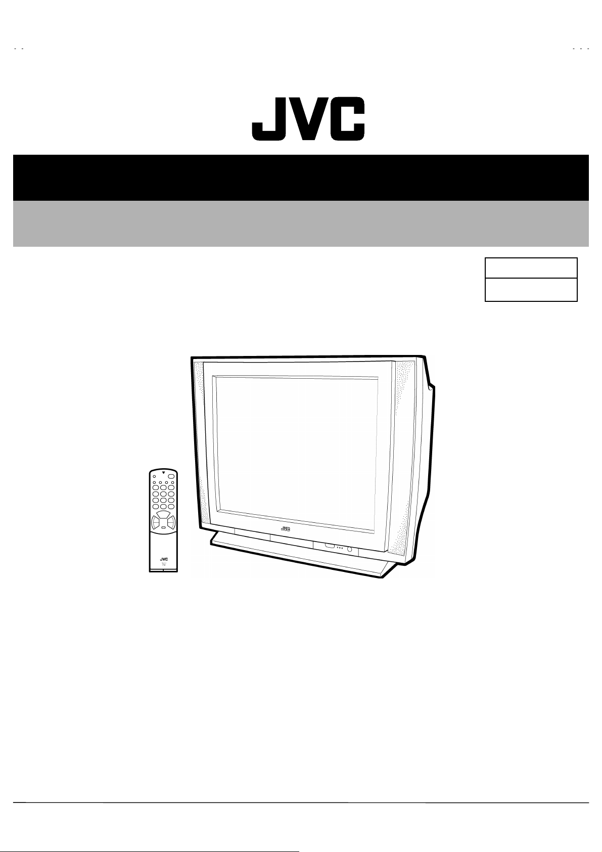
SERVICE MANUAL
COLOUR TELEVISION
HV-L34PRO
BASIC CHASSIS
MF
HV-L34PRO
/K
CONTENTS
SPECIFICATIONS
SAFETY PRECAUTIONS
FEATURES
FUNCTIONS
SPECIFIC SERVICE INSTRUCTIONS
SERVICE ADJUSTMENTS
PARTS LIST
★
OPERATING INSTRUCTIONS
★
STANDARD CIRCUIT DIAGRAM
1
・・・・・・・・・・・・・・・・・・・・・・・・・・・・・・・・
・・・・・・・・・・・・・・・・・・・・・・・・・・・・・・・・・・・・・・・・・・・・・・・・・・・・・・・・・・・・・・
・・・・・・・・・・・・・・・・・・・・・・・・・・・・・・・・・・・・・・・・・・・・・・・・・・・・・・・・・・・・・・・・
・・・・・・・・・・・・・・・・・・・・・・・・・・・・・・・・
・・・・・・・・・・・・・・・・・・・・・・・・・・・・・・・・・・・・・・・・・・・・・・・・・・・・・・・・
・・・・・・・・・・・・・・・・・・・・・・・・・・・・・・・・・・・・・・・・・・・・・・・・・・・・・・・・・・・・・・・・
・・・・・・・・・・・・・・・・・・・・・・・・・・・・・・・・
・・・・・・・・・・・・・・・・・・・・・・・・・・・・・・・・・・・・・・・・・・・・・・・・・・・・・・・・・・・・・・・・
・・・・・・・・・・・・・・・・・・・・・・・・・・・・・・・・・・・・・・・・・・・・・・・・・・・・・・・・・・・・・・・・
・・・・・・・・・・・・・・・・・・・・・・・・・・・・・・・・
・・・・・・・・・・・・・・・・・・・・・・・・・・・・・・・・・・・・・・・・・・・・・・・・・・・・・・・・・・・・・・・・
・・・・・・・・・・・・・・・・・・・・・・・・・・・・・・・・・・・・・・・・・・・・・・・・・・・・・・・・・・・・・・・・
・・・・・・・・・・・・・・・・・・・・・・・・・・・・・・・・
・・・・・・・・・・・・・・・・・・・・・・・・・・・・・・・・・・・・・・・・・・・・・・・・・・・・・・
・・・・・・・・・・・・・・・・・・・・・・・・・・・・・・・・・・・・・・・・・・・・・・・・・・・・・・・・・・・・・・・・
・・・・・・・・・・・・・・・・・・・・・・・・・・・・・・・・
・・・・・・・・・・・・・・・・・・・・・・・・・・・・・・・・・・・・・・・・・・・・・・・・・・・・・・・・・・・・・・・・
・・・・・・・・・・・・・・・・・・・・・・・・・・・・・・・・・・・・・・・・・・・・・・・・・・・・・・・・・・・・・・・・
COPYRIGHT © 2001 VICTOR COMPANY OF JAPAN, LTD.
・・・・・・・・・・・・・・・・・・・・・・・・・・・・・・
・・・・・・・・・・・・・・・・・・・・・・・・・・・・・・・・・・・・・・・・・・・・・・・・・・・・・・・・・・・・
・・・・・・・・・・・・・・・・・・・・・・・・
・・・・・・・・・・・・・・・・・・・・・・・・・・・・・・・・・・・・・・・・・・・・・・・・
・・・・・・・・・・・・・・・・・・・・・・・・・・・・・・・・・・・
・・・・・・・・・・・・・・・・・・・・・・・・・・・・・・・・・・・・・・・・・・・・・・・・・・・・・・・・・・・・・・・・
・・・・・・・・・・・・・・・・・・・・・・・・・・・・・・・・・・
・・・・・・・・・・・・・・・・・・・・・・・・・・・・・・・・・・・・・・・・・・・・・・・・・・・・・・・・・・・・・・・・
・・・・・・・・・・・・・・・・・・・・・・・・・・・・・・・・
・・・・・・・・・・・・・・・・・・・・・・・・・・・・・・・・・・・・・・・・・・・・・・
・・・・・・・・・・・・・・・・・・・・・・・・・・・・・・・・・・・・・・・・・・・・・・・・・・・・・・・・・・・・・・・・
・・・・・・・・・・・・・・・・・・・・・・
・・・・・・・・・・・・・・・・・・・・・・・・・・・・・・・・・・・・・・・・・・・・
・・・・・・・・・・・・・・・・・・・・・・・・・・・・・・・・・・・・
・・・・・・・・・・・・・・・・・・・・・・・・・・・・・・・・・・・・・・・・・・・・・・・・・・・・・・・・・・・・・・・・
・・・・・・・・・・・・・・・・・・・・・・・・・・・・・・・・
・・・・・・・・・・・・・・・・・・・・・・・・・・・・・・・・・・・・・・・・・・・・・・・・・
・・・・・・・・・・・・・・・・・・・・・・・・・・・・・・・・・・・・・・・・・・・・・・・・・・・・・・・・・・・・・・・・
・・・・・・・・・・・・・・
・・・・・・・・・・・・・・・・・・・・・・・・・・・・
・・・・・・・・・・・・・・・・・
・・・・・・・・・・・・・・・・・・・・・・・・・・・・・・・・・・
・・・
・・・・・・
・・
・・・・
14
37
2-1
2
3
4
6
8
No.51938
Jul. 2001
Page 2
HV-L34PRO
SPECIFICATIONS
Item Content
Dimensions ( W
Mass
TV RF System
Colour System
Stereo System
Receiving
Frequency
Intermediate
Frequency
Color Sub Carrier
Frequency
Power Input
Power Consumption
Aerial Input Term
Picture Tube
High Voltage
Audio Power Output
Speaker (Dome Speaker)
Input
Terminal
Output Video
Terminal
AV Compulink
Headphone jack
Remote Control Unit
D )
××××H××××
Operated Voltage
Video
Audio(L/R)
S / Video
Component Cb/Cr
Audio(L/R)
VL
VH
UHF
CATV
VIF
SIF
PAL
SECAM
NTSC
Rated Voltage
89.8cm×72.8cm×57.9cm
75.0kg
B/G, I, D/K, K1, M
PAL / SECAM / NTSC 3.58 / NTSC 4.43
A2 (B/G) / NICAM (B/G, I, D/K, K1)
46.25MH z ~ 168.25MHz
175.25MHz ~ 463.25MHz
471.25MHz ~ 863.25MHz
Mid (X~Z+2, S1~S10), Super (S11~S20) & Hyper (S21~S41)
38.0MHz
32.5MHz(5.5MHz) / 32.0MHz(6.0MHz) / 3.15MHz(6.5MHz) / 33.5MHz (4.5MHz)
4.43MHz
4.40625MHz / 4.25MHz
3.58MHz / 4.43MHz
AC 110V~220V , 60Hz
AC 110V~240V , 50/60Hz
Max 255W / Avg. 170W
75Ωunbalanced, Coaxial
34”(87cm) measured diagonally
+1.0kV
32.0kV (At zero beam current )
20W + 20W
φ
1Vp-p 75
500mVrms(-4dBs), High Impedanc e
Y : 1V(p-p) Positive (Negative sync provided) 75
C : 0.286V(p-p) ( burst signal), 75
Y : 1V(p-p), 75
Cb : B-Y 0.7V(p- p), 75Ω / Cr : R-Y 0.7V(p-p), 75
1V(p-p) 75
500mVrms(-4dBs), Low Impedanc e
Mono mini jack (φ3.5mm )
Stereo mini jack (φ3.5mm )
RM-C215 (AA/R06 / UM-3 , Dry cell battery×2)
-1.5kV
12cm Round type×2 / φ3.5cm Round type×2
Ω
Ω
Ω
Ω
Ω
Ω
Design & specifications are subject to change without notice
2
No.51938
.
Page 3
SAFETY PRECAUTIONS
HV-L34PRO
1. The design of this product contains special hardware, many
circuits and components specially for safety purposes. For
continued protection, no changes should be made t o the original
design unless authorized in writing by the manufacturer.
Replacement parts must be identical to those us ed in the original
circuits. Service should be performed by qualified personnel
only.
2. Alterations of the design or circuitry of the products should not be
made. Any design alterations or additions will void the
manufacturer's warranty and will further relieve the manufacturer
of responsibility for personal injury or property damage resulting
theref rom.
3. Many electric al and mechanical parts in the products have
special safety-related characteristics. These characteristics are
often not evident from visual inspection nor can t he protection
afforded by them necessarily be obtained by using replacement
components rated for higher voltage, wattage, etc. Replacement
parts which have these special safety characteristics are
identified in the parts list of Service manual.
components having such features are identified by shading
on the schematics and by (
manual.
have the s ame safety char acteristics as the recommended
replacement part shown in the parts list of S ervice manual may
cause shock, fire, or other hazards.
The us e of a substitute replacement which does not
) on the parts list in Service
Electrical
4.
Don't short between the LIVE side ground and ISOLATED
(NEUTRAL) side ground or EARTH side ground when
repairing.
Some model's power circuit is partly different in the GND. The
differenc e of the GND is shown by the LIVE : () side GND, the
ISOLATED(NEUTRAL) : () side GND and EARTH : () side
GND. Don't short between the LIVE side GND and
ISOLATED(NEUTRAL) side GND or EARTH side GND and
never meas ure with a measuring apparatus (oscillosc ope etc.)
the LIVE side GND and ISOLATED(NEUTRAL) side GND or
EARTH side GND at the same time.
If above note will not be kept, a fuse or any parts will be broken.
5. If any repair has been made to the chassis, it is recommended
that the B1 setting should be checked or adjust ed (See
ADJUSTMENT OF B1 POWER SUPPLY).
6. The high voltage applied to the picture tube must conform with
that specified in Servic e manual. E xcessive high voltage can
cause an incr ease in X-Ray emission, arcing and possible
component damage, therefore operation under excessive high
voltage conditions should be kept to a minimum, or should be
prevented. If s evere arcing occurs, remove the AC power
immediately and determine the cause by visual inspection
(incorrect installation, cracked or melted high voltage harness,
poor soldering, etc.). To maintain the proper minimum level of
soft X-Ray emission, components in the high voltage circuitr y
including the picture tube must be the exact replacements or
alternatives approved by the manufacturer of the c omplete
product.
7. Do not check high voltage by drawing an arc. Use a high voltage
meter or a high voltage probe with a VT VM. Discharge the
picture tube before attempting meter connection, by connecting
a clip lead to the ground frame and connecting the other end of
the lead through a 10k: 2W resistor to the anode button.
8. W hen service is required, observe the original lead dress. Extra
precaution should be given to assure c orrect lead dress in the
high voltage circuit area. W here a short circuit has occ urred,
those components that indicate evidence of overheating should
be replaced. Always use the manuf acturer's replacement
components.
9.
Isolation Check
(Safety for Electrical Shock Hazard)
After re-assembling the product, always perform an isolation
check on the exposed metal parts of the cabinet (antenna
terminals, video/audio input and output terminals, Control knobs,
metal c abinet, screwheads, earphone jack, control shafts, etc.)
to be sure the product is safe to operate without danger of
electr ic al shock.
(1)
Dielectric Strength Test
The isolation between the AC primary circuit and all metal parts
exposed to the user, particularly any exposed metal part having a
return path to the chassis should withstand a voltage of 3000V
AC (r.m.s.) for a period of one second.
(. . . . Withstand a voltage of 1100V AC (r.m.s.) to an appliance
rated up to 120V, and 3000V AC (r.m.s.) to an appliance rated
200V or more, for a period of one second.)
This method of test requires a test equipment not generally f ound
in the s ervice trade.
(2)
Leakage Current Check
Plug the AC line cord directly into the AC outlet (do not use a line
isolation transformer during this check.). Using a "Leakage
Current T ester", measure the leakage current from each exposed
metal part of the cabinet, particularly any exposed metal part
having a return path to the chassis, to a known good earth
ground (water pipe, etc.). Any leakage curr ent must not exceed
0.5mA AC (r.m.s.).
However, in tropical area, this must not exceed 0.2mA AC
(r.m.s.).
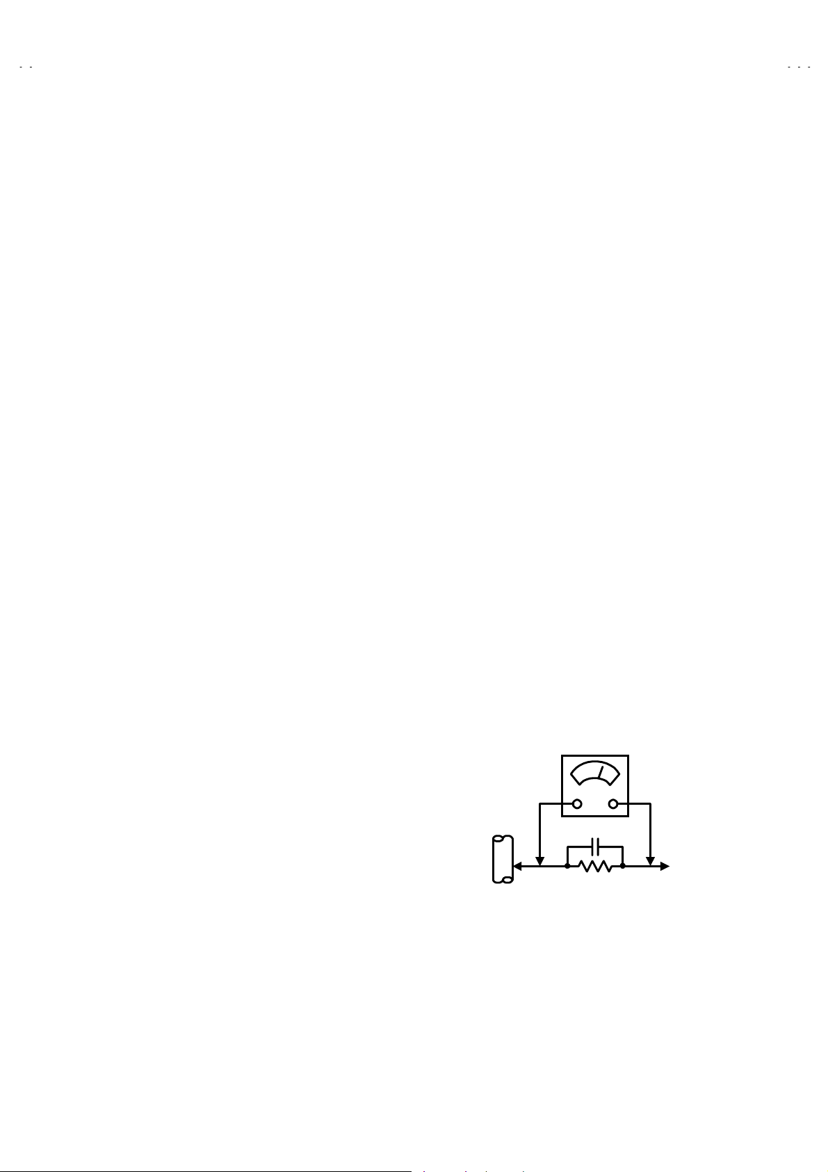
Alternate Check M ethod
zzzz
Plug the AC line cord directly into the AC outlet (do not use a line
isolation transformer during this check.). Use an AC voltmeter
having 1000 ohms per volt or more sensitivity in the following
manner. Connect a 1500: 10W resistor paralleled by a 0.15PF
AC-type capacitor between an exposed metal part and a known
good earth ground (water pipe, etc.). Measure the AC voltage
across the resistor with the AC voltmeter. Move the resistor
connection to each exposed metal part, particularly any exposed
metal part having a retur n path to the chassis, and measure the
AC voltage across the resistor. Now, reverse the plug in the AC
outlet and repeat each measurement. Any voltage measured
must not exceed 0.75V AC (r.m.s.). This corresponds to 0.5mA
AC (r.m.s.).
However, in tropical ar ea, this must not exceed 0.3V AC (r.m.s.).
This corresponds to 0.2mA AC (r.m.s.).
AC VOLTMETER
0.15μF AC-T YPE
1500
GOOD EARTH GROUND
:
(HAVING 1000
OR MORE SENSITIVITY)
10W
/V,
:
PLACE THIS PROBE
ON EACH EXPOSED
METAL PART
No.51938
3
Page 4

HV-L34PRO
FEATURES
New chassis design enable use of an interactive on screen
z
control.
Pure FLAT CRT reproduce fine textured.
z
Digi Pure pro : Auto digi pure with motion pictur e compensation.
z
Because this TV unit corresponds to multiplex broadcast, users
z
can enjoy music programs and sporting events with live realism.
In addition, BILINGUAL programs can be heard in their original
language.
Built-in ECO (ECONOMY, ECOLOGY) MODE.
z
In accordance with the brightness in a room, the brightness
and / or contrast of the picture can be adjusted automatically to
make the optimum picture which is easy on the eye.
4
No. 51938
Page 5
SYSTEM BLOCK DIAGRAM
MICON PWB
HV-L34PRO
IC004
MEMORY
SDA 0
SCL
0
SDA 2
SCL 2
IC001
MICRO COMPUTER
SDA 1
SCL
1
MAIN PWB
IC701
BBE CONTROL
IC101
MULTI SOUND
PROCESSOR
IC301
DEF & RGB
PROCESSOR
TU001
TUNER
SYNC SEP PWB 100Hz PWB
IC301
SYNC SEP PWB
AV SW PWB
IC101
SW
TU001
TUNER
IC101
VIDEO PROCESS
&
CODEC MAIN
IC151
VIDEO PROCESS
&
CODEC SUB
IC201
SAMPLE RATE
CONVERTER
IC301
ENHANCE
No. 51938
5
Page 6
HV-L34PRO
FUNCTIONS
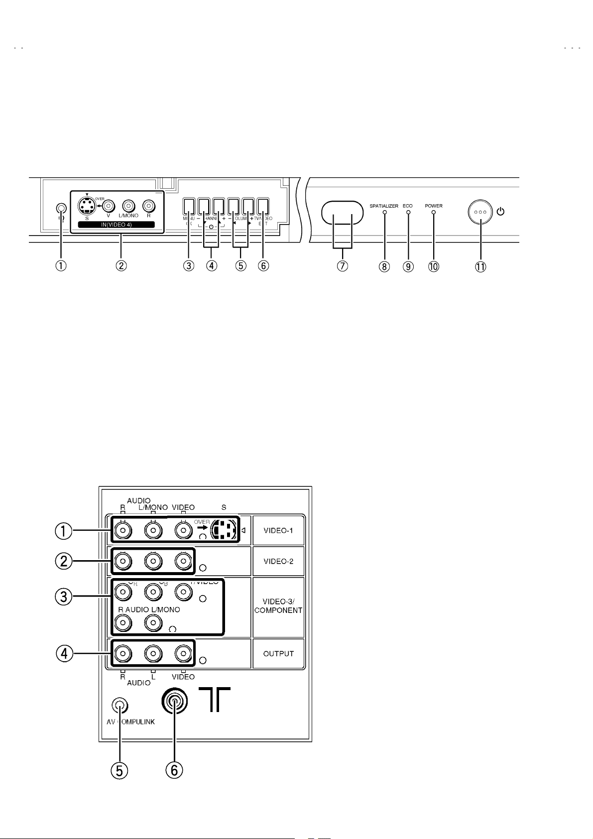
■■■■
Front Terminal & Control
1
2
3
4
5
6
■■■■
Rear Terminal
Headphone jack
Video-4 T erminal (S-VIDEO / VIDEO / L/MONO / R)
MENU/OK Button
Channel -/+ (MENU UP/DOWN) Button
VOLUME -/+ (MENU LEFT/RIGHT) Button
TV/VIDEO / EXIT Button
SENCER (Remote Control & ECO)
7
SPATIALIZER Lamp
8
ECO Lamp
9
POWER Lamp
A
POWER SW Button
B
Video-1 (INPUT) Terminal (S, V, L, R)
1
Video-2 (INPUT) Terminal (V, L, R )
2
Video-3 (INPUT) Terminal (V/Y, Cb, Cr, L, R)
3
Output (AUDIO/VIDEO) T erminal (V, L, R)
4
AV COMPULINK T erminal
5
Aerial socket
6
6
No. 51938
Page 7
■■■■
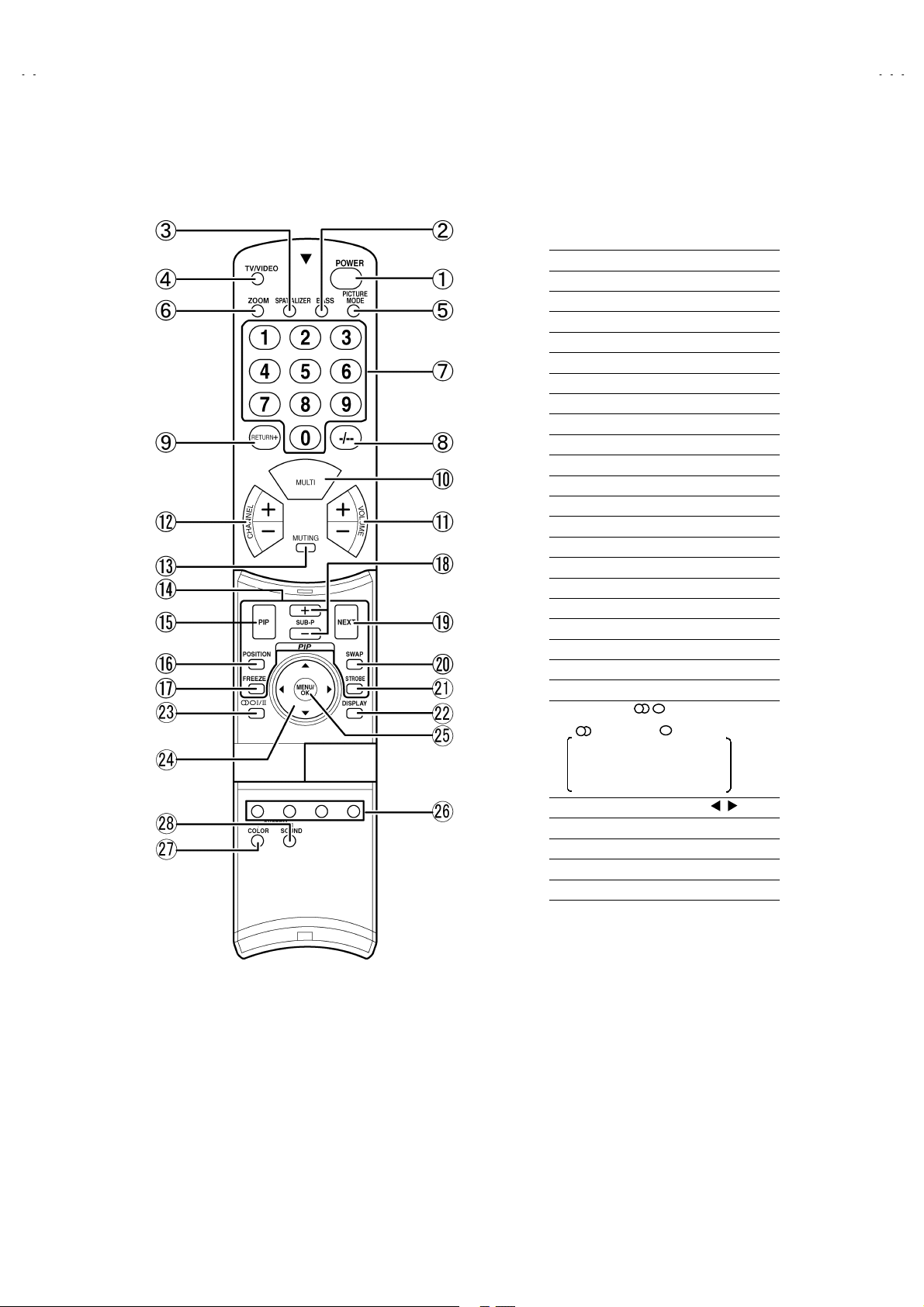
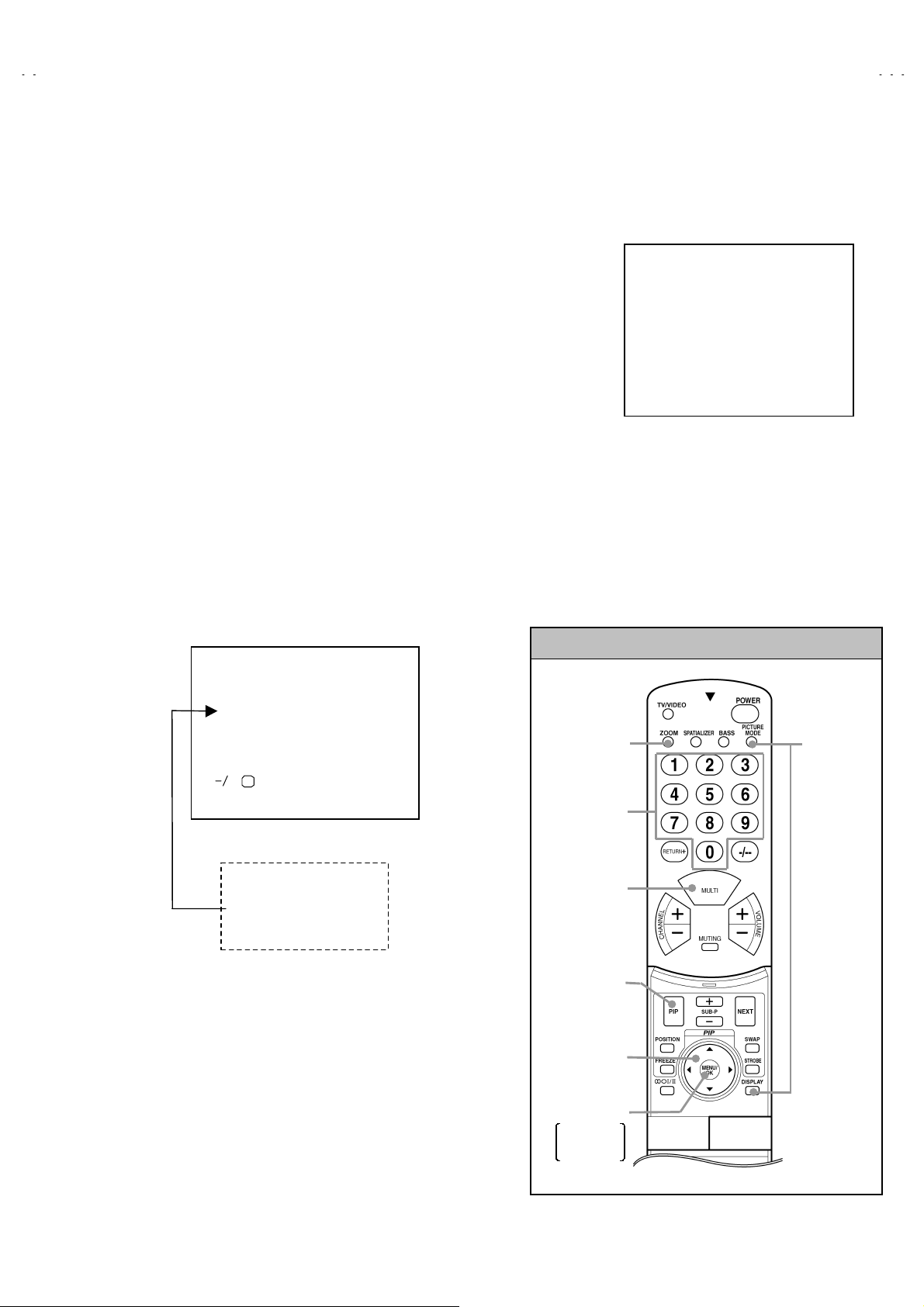
Remote Control Unit
POWER Key
1
BASS Key
2
SPATIALIZER Key
3
TV/VIDEO Key
4
PICTURE MODE Key
5
ZOOM Key
6
CHANNEL Key
7
-/-- Key
8
RETURN + Key
9
MULTI Key
A
VOLUME +/- Key
B
CHANNEL +/- Key
C
MUTING Key
D
PIP MODE
E
PIP Key
F
POSITION Key
G
FREEZE Key
H
SUB P (PIP)+&- Key
I
NEXT Key
J
SWAP Key
K
STROBE Key
L
DISPLAY Key
M
STEREO Ⅰ/ⅡKey
N
: Stereo / : Mono
: Bilingual (subⅠ)
Ⅰ
: Bilingual (subⅡ)
Ⅱ
HV-L34PRO
FUNCTION Key(▲/▼&
O
MENU/OK Key
P
COLOR Key
Q
COLOR SYSTEM Key
R
SOUND SYSTEM Key
S
/ )
No. 51938
7
Page 8
HV-L34PRO
SPECIFIC SERVICE INSTRUCTIONS
DISASSEMBLY PROCEDURE
REMOVING THE REAR COVER
1. Unplug the power cord.
2. Remove the 18 screws marked
3. W ithdraw the rear cover toward you.
as shown in the Fig. 1.
####
REMOVING THE AV TERMINAL BOARD
After removing the rear cover.
z
1. Remove the 5 screws marked
2. W ithdraw the AV terminal board towar d you.
as shown in the Fig. 1.
$$$$
REMOVING THE CHASSIS
After removing the rear cover.
z
1. Slightly raise the both sides of the chassis by hand and remove
the 2 claws under the both sides of the chassis from the front
cabinet.
2. W ithdraw the chassis backward.
(If necessary, take off the wire clamp, connectors etc.)
REMOVING THE DOME SPEAKER BOX / SPEAKER
After removing the rear cover.
z
1. As shown in Fig. 1, remove the 2 screws marked
remove the dome speaker box.
2. Remove the 5 scr ews marked
remove the dome box.
3. Remove the 4 scr ews marked
remove the speaker.
4. Follow the same steps when removing the other hand dome
speaker box.
: When removing the screws marked
NOTE
box, remove the lower side scr ew first, and then remove the
upper one.
as shown in the Fig.2, then
&&&&
as shown in the Fig.2, then
''''
of the dome speaker
%%%%
%%%%
, then
CHECKING THE PW BOARD
To check the back side of the PW Board.
1) Pull out the chassis. (Refer to REMOVING THE CHASSIS).
2) Erect the chassis vertically so that you can easily check the
back side of the PW Board.
[CAUTION]
W hen erecting the chassis, be careful so that there will be no
z
contac ting with other PW Boar d.
Before turning on power, make sure that the wire connector is
z
properly connected.
When conducting a check with power supplied, be sure to confir m
z
that the CRT EARTH WIRE (BRAIDED ASS’Y) is connected to
the CRT SOCKET PW board.
WIRE CLAMPING AND CABLE TYING
1. Be sure to clamp the wire.
2. Never remove the cable tie used for tying the wires together.
Should it be inadvertently removed, be sure to tie the wires with
a new cable tie.
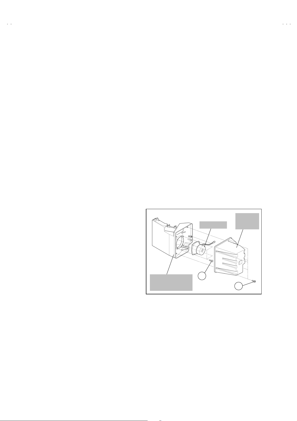
DOME SPEAKER BOX
z
DOME
SPEAKER
SPEAKER
BOX
REMOVING THE TWEETER SPEAKER
After removing the rear cover.
z
1. As shown in Fig. 1, remove the 2 screws marked
out the tweeter speaker to remove it.
8
, then pull
((((
No.51938
DOME
SPEAKER
(Hone & Hone Panel)
(×4)
Fig. 2
E
(×5)
D
Page 9
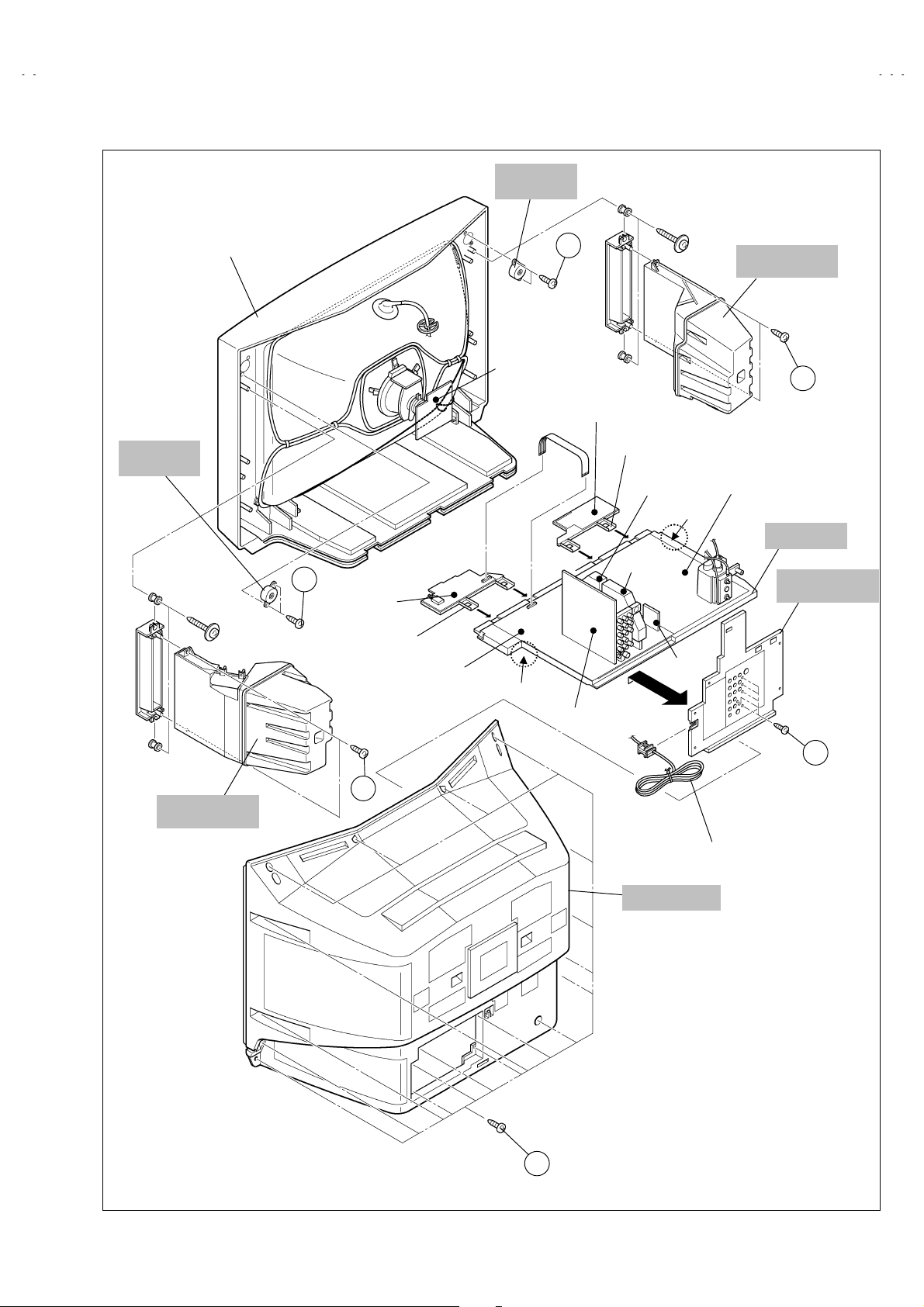
TWEETER
SPEAKER
HV-L34PRO
TWEETER
SPEAKER
FRONT CABINET
F
FRONT
CONTROL
PWB (R)
CONTROL
BASE
MAIN PWB
CRT
SOCKET
PWB
CLAW
F
FRONT
CONTROL
PWB (L)
CONTROL
BASE
AV SW PWB
MICON
PWB
100Hz
PWB
CLAW
BLK
PWB
DOME
SPEAKER BOX
POWER & DEF
PWB
CHASSIS
AV TERMINAL
BOARD
C
DOME
SPEAKER BOX
B
C
POWER CORD
REAR COVER
(×18)
A
(×5)
Fig. 1
No.51938
9
Page 10
HV-L34PRO
A
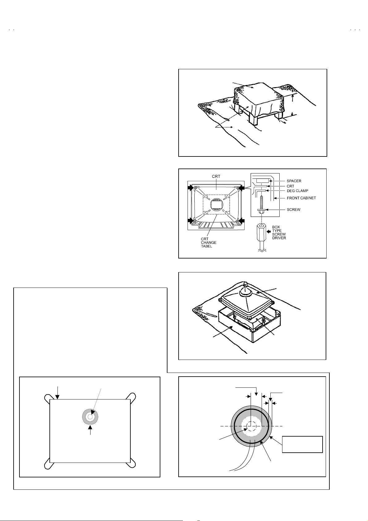
REMOVING THE CRT
Replacement of the CRT should be performed by 2 or more
persons.
After removing the cover, chassis etc.,
x
1. Putting the CRT change table on soft cloth, the CRT change table
should also be covered with such soft cloth (shown in Fig. 3).
2. W hile keeping the surface of CRT down, mount the TV set on the
CRT change table balanced will as shown in Fig.4.
3. Remove 4 screws marked by arrows with a box type screw driver
as shown in Fig.4.
Sinc e the cabinet will drop when scr ews have been removed, be
x
sure to support the cabinet with hands.
4. After 4 screws have been r emoved, put the cabinet slowly on
cloth (At this time, be carefully so as not to damage the front
surface of the cabinet) shown in Fig.5.
The CRT should be assembled according to the opposite
x
sequence of its dismounting steps.
The CRT change table should preferably be smaller that the CRT
surface, and its height be about 35cm. (Fig.3)
About CRT Spacer (Fig.4)
An appropriate CRT spacer should be us ed in the corresponding
CRT in accordance with the type of the CRT.
When a CRT is replaced, special attention should be paid to this
matter.
CRT CHANGE TABLE
CLOTH
Fig. 3
PPROX.
35cm
COATING OF SILICON GREASE FOR ELECTRICAL
INSULATION ON THE CRT ANODE CAP SECTION.
Subs equent to replacement of the CRT and HV transformer or
x
repair of the anode cap, etc. by dismounting them, be sure to
coat silicon grease for electrical insulation as shown in Fig.6.
Wipe around the anode button with clean and dry cloth. (Fig.6)
Coat silicon grease on the s ection around the anode button. At
this time, take care so that any silicon greases dose not stick to
the anode button. (Fig.7)
Silicon grease product No. KS - 650N
★★★★
CRT
Anode button
Silicon grease
coating
CABINET
Approx.
20mm (Do not
coat greas e on
this section
Anode button
(N o sticking of
silicon gr ease)
Fig. 4
CRT
CRT
CHANGE TABLE
Fig. 5
Silicon grease
should be coated
by 5mm or more
from the outside
diameter of
anode cap.
Coating position
of silicon grease
Anode c ap
Fig. 6 Fig. 7
10
No. 51938
Page 11
REPLACEMENT OF MEMORY ICs
1. Memory ICs
This TV use memory ICs. In the memory ICs, there are memorized data
for correctly operating the video and deflection circuits. W hen replacing
memory ICs, be sure to use ICs written with the initial values of data.
HV-L34PRO
2. Procedure for replacing memory ICs
(1)
Power off
Switch the power off and unplug the power cord from the wall outlet.
(2)
Replace ICs
Be sure to use memory ICs written with the initial data values.
(3)
Power on
Plug the power c ord into the wall outlet and switch the power on.
(4)
Check and set SYSTEM CONSTANT SET:
It must not adjust without signal.
****
.
1. IF 2. V/C
3. AUDIO 4. DEF
5. VSM PRESET 6. STATUS
7. PIP 8. WB PRESET
9. SHIPPING(OFF) 0. BUS FREE
1-0 : SELECT D ISP : EXIT
SERVICE MENU
Fig.1
1) Press the DISPLAY key and the PICTURE MODE key of the REMOTE CONTROL UNIT simultaneously.
2) The SERVICE MENU screen of Fig. 1 will be displayed.
3) While the S ERVICE MENU is dis played, press the DISPLAY key and PICTURE MOD E key simult aneously, and the SYSTEM
CONSTANT SET screen of Fig. 2 will be dis played.
4) Check the setting values of the SYSTEM CONSTANT SET of Table 1. If the value is different, select the setting item with the
FUNCTION UP/DOWN key, and set the correct value with the FUNCTION LEFT/RIGHT key.
5) Press the MENU(OK) key to memorize the setting value.
6) Press the DISPLAY key, and return to the normal screen.
SERVICE MENU KEY
SYSTEM CONSTANT SET
1. TEXT
**
OK
+ : STORE DISP : EXIT
Fig.2
**
**
**
**
**
(5)
Setting of receive channels
2. BLUE BACK MUTE
3. E.M.C
4. WHITE BACK
5. COLOUR AUTO
6. PICTURE TILT
Set the r eceive c hannel.
For setting, refer to the OPERATING INSTRUCTIONS.
(6)
Setting of SERVICE MENU
Verify the setting items of the
SERVICE MENU
of Table 2, and
reset where necessary.
For setting, refer to the SERVICE ADJUSTMENTS.
(7)
User settings
Check the user setting values of Table 3, and if setting value is
different , set the correct value.
For setting, refer to the OPERATING INSTRUCTIONS.
ZOOM
(ASPECT )
key
SETTING ITEM
SELECT key
(Numbers key)
PICTURE
CONTENTS
key
PIP key
FUNCTION key
(UP/DOWN &
LEFT/RIGHT key)
MENU/OK key
MEMORY
(STORE)
key
SERVICE
MENU/
&SYSTEM
CONSTANT
key
No. 51938
11
Page 12
HV-L34PRO
SETTING VALUES OF SYSTEM CONSTANT SET (TABLE 1)
Setting item Setting value
1. TEXT NO
2. BLUE BACK MUTE
3. E. M. C
4. WHITE BACK
5. COLOUR AUTO
6. PICTURE TILT YES
↑
↑
↑
↑
SERVICE MENU SETTING ITEMS (TABLE 2)
Setting item Setting value Setting item Setting value
1. IF 1. VCO
2. ATT ON / OFF
2. V / C 1. RGB BLK
2. WDR R
3. WDR G
4. WDR B
5. BRIGHT
6. CONTRAST
7. COLOR
8. HUE
9. SHARP
11. VID AGC
12. SYC SLI
5. VSM PRESET
BRIGHT
STANDARD
SOFT
6. STATUS
(Do not adjust)
(Don’t change)
1. CONT.
2. BRIGHT
3. SHARP
4. COLOR
5. TINT
1. SOFT
2. TELETEXT
ASPECT
3.
Indicated for STATUS.
*
This is not related to the adjustment.
3. AUDIO
(Do not adjust)
4. DEF. 1. V-SHIFT
1. ERR LI MIT
2. A2 ID THR
3. QUASI
2. V-SIZE
3. H-CENT
4. H-SIZE
5. TRAPEZ
6. EW-PIN
7. COR-PIN
8. COR-UP
9. COR-LO
10. ANGLE
11. BOW
12. V-S.CR
13. V.LIN
14. V.BLK-UP
12
7. PIP 1. PIP VCO ADJ
8. WB PRESET 1. WDR R
9. SHIPPING (OFF)
0. BUS FREE.
No. 51938
2. PIP VID AGC
3. PIP SYC SLI
2. WDR G
3. WDR B
Don’t select under the adjustment as this
*
menu is set in ON after the inspection.
When users press the MAIN POWER
*
button, the JVC logo appears. If they press
any keys, the LANGUAGE menu appears.
*
Don’t Adjust.
Page 13

USER SETTING VALUES (TABLE 3)
Setting item Setting value Setting item Setting value
MAIN POWER SW OFF SUB POWER ON
SHIPPING CHANNEL PR1 DISPLAY INDICATED
HV-L34PRO
PRESET CHANNEL
PICT URE SETTING INST ALL
PICTURE MODE BRIGHT LANGUAGE
WHITE BALANCE COOL EDIT
ECO MODE OFF
PICT URE FEAT URES FEAT URES
DIGITAL VNR AUTO SLEEP TIMER OFF
DIGI PURE AUTO BLUE BACK ON
COLOR SYSTEM
ZOOM MODE REGURER
ASPECT MODE REGULAR PULL DOWN AUTO
BASS
TREBLE
BALANCE
See ; OPERATING
INSTRUCTIONS.
TV : Depends on preset ch.
z
EXT : AUTO
z
CENTER
CENTER
CENTER
VOLUME LEVEL 10
ENGLISH
PRESET CHANNEL ONLY
z
OTHER : NON (SPACE)
z
AUTO SHUT OFF OFF
VIDEO-3 SETTING COMPONENT
CHILD LOCK OFF (for all the channels)
SOUND
BBE ON
SUPER BASS ON
AI VOLUME ON
SPATIALIZER
VOLUME
TV SPEAKER
OUTPUT
OFF
HEAD PHONE EXT SETTING
5
OFF
MAIN
EXT SETTING ID (space)
S-IN (space)
No. 51938
13
Page 14

HV-L34PRO
SERVICE ADJUSTMENTS
BEFORE STARTING SERVICE ADJUSTMENT
1.
There are 2 ways of adjusting this TV: One is with the
REMOTE CONTROL UNIT and the other is the conventional
method using adjustment parts and components.
2.
The setting (adjustment) using the REM OTE CONTROL
UNIT is made on the basis of the initial setting values. The
setting values which adjust th e screen to the opt imum
condition can be different from the initial setting values.
3. Make sure that connection is correctly made to AC power
source.
4. Turn on the power of the TV and measur ing instrument for
warming up for at least 30 minutes befor e starting adjustment.
5. If the receive or input signal is not specified, us e the most
appropriate signal for adjustment.
6.
Never touch parts
condensers)
service adjustment.
(such as variable resistors, transformers and
not shown in the adjustment items of this
7. Preparation for adjustment ( presetting):
Unless otherwise specified in the adjustment items, preset the
following functions with the REMOTE CONTROL UNIT:
Setting position
z
PICTURE MODE (VSM) BRIGHT
SLEEP TIMER OFF
BALANCE CENTER
ECO MODE OFF
ZOOM MODE REGULAR
MEASURING INSTRUMENT AND FIXTURES
1. DC voltmeter (or digital voltmeter)
2. Oscilloscope
3. Signal generator (Pattern generator) [PAL / SECAM / NTSC]
4. Remote contr ol unit
ADJUSTMENT ITEMS
Checking items.
●
Adjustment of FOCUS & SCREEN.
●
VSM PRESET setting.
●
VIDEO / CHROMA circuit adjustment.
●
DEFLECTION circuit adjustment.
●
AUDIO circuit adjustment.
●
(Do not adjust)
14
No. 51938
Page 15

ADJUSTMENT LOCATIONS
HV-L34PRO
FRONT CONTROL PWB (R)
POWER SW
FRONT
FRONT
AV SW PWB
POWER
F901
PW
Power cord
CN111
Speaker
TUNE R 2
CN001
C901
TUNE R
TV/V IDEO EXT
VOL UP
VOL DOWN
ECO
SPETIALIZER
LF901
CDS
W
J
CN002
MAIN PWB POWER&DEF PWB
CN002
R3
MICON PWB
W DEG
CN004
CN007
100Hz PW B
CN005
SYNC
PWB
CN003
BLK PWB
CN006
S
IN
CN013
C1
FRONT CONTROL PWB (L)
S IN
F
To AV SW PWB
HVT
CH UP
J
MENU/
OK
CH DOWN
CN014
R4 L4 V4
IN (VIDEO-4)
HV
HEAD
PHONE
X
1
5
FRONT
FRONT
1pin:B1(TP-91)
2pin:NC
3pin :X-RAY
4pin :X-RAY
5pin:GND
FRONT
F
F. CONT.(L) PWB
YHC
(VR2)
CRT
XV COIL
ANT-IN
YV
(VR1)
CRT SOCKET
PWB
CN013
(SOLDER SIDE)
No. 51938
TP-E
TP-Y
VR
FOCUS-2
E1
TP-47B
CN014
VM
VM
TOP
FOCUS 1
VR
SCREEN
VR
15
Page 16

HV-L34PRO
BASIC OPERATION SERVICE MENU
1. TOOL OF SERVICE MENU OPERATION
Operate the SERVICE MENU with the REMOTE CONTROL UNIT.
2. SERVICE MENU ITEMS
With the SERVICE MENU, various settings (adjustments) can be made, and they are broadly classified in the f ollowing items of s ettings
(adjustments):
(1)
(2)
(3)
(4)
1. IF
・・・・・・・・・・・・・・・・・・・・・・・・・・・・・・
2.V/C
・・・・・・・・・・・・・・・・・・・・・・・・・・・・・
3.AUDIO
4.DEF
・・・・・・・・・・・・・・・・・・・・・・・・・・
・・・・・・・・・・・・・・・・・・・・・・・・・・・・・
ZOOM (ASPECT) V. FREQ.
REGULAR 100Hzi / 60Hzp
ZOOM
16 : 9
This mode adjusts the s etting values of the IF circuit.
This mode adjusts the setting values of the VIDEO / CHROMA circuit.
This mode adjusts the setting values of the SOUND circuit. (D o not adjust)
This mode adjusts the setting values of the DE FLECTION circuit for each aspect mode given
below.
↑
↑
(5)
5.VSM PRESET
(6)
6.STATUS
(7)
7.PIP
・・・・・・・・・・・・・・・・・・・・・・・・・・・・・
(8)
8.WB PRESET
(9)
9.SHIPPING(OFF)
(10)
0.BUS FREE
・・・・・・・・・・・・・・・・・・・・
・・・・・・・・・・・・・・・・・・・・・・・・・
・・・・・・・・・・・・・・・・・・・・・
・・・・・・・・・・・・・・・・・・
・・・・・・・・・・・・・・・・・・・・・・
This mode adjusts the initial setting values of Bright, Standard & soft.
(VSM : Video Status Memory)
It is no requir ement to adjustment.
This mode adjusts the setting values of the PIP circuit. (PIP : Picture In Picture)
This mode adjusts the setting values of the WHITE BALANCE.
This mode adjusts the setting values of the channel presettings.
If you turn the SHIPPING position set ON.
This setting becomes channel presetting automatically.
Also you turn the TV power off, this setting become OFF position automatically.
It is not requirement to adjustment.
16
No. 51938
Page 17

3. BASIC OPERATION OF SERVICE MENU
(1)
How to enter SERVICE MENU
Press the PICTURE MODE key and the DISPLAY key of the
REMOTE CONTROL UNIT of Fig2 simultaneously, and the
SERVICE MENU screen of Fig. 1 will be displayed.
(2)
Selection of SUB MENU SCREEN
Press one of keys 1~0 of the REMOTE CONTROL UNIT and
select the SERVICE MENU SCREEN (See Fig. 3), form the
SERVICE MENU.
SERVICE MENU → SUB MENU
1. IF
2. V / C
3. AUDIO (Do not adj.)
4. DEF.
5. VSM PRESET
6. STATUS (Do not adj.)
7. PIP
8. WB PRESET
9. SHIPPING (OFF)
0. BUS FREE
ZOOM
(ASPECT )
key
SETTING ITEM
SELECT key
(Numbers key)
SERVICE MENU
SERVICE MENU
1. IF 2. V/C
3. AUDIO 4. DEF
5. VSM PRESET 6. STATUS
7. PIP 8. WB PRESET
9. SHIPPING(OFF) 0. BUS FREE
1-0 : SELECT D ISP : EXIT
Fig.1
SERVICE MENU KEY
HV-L34PRO
SERVICE
MENU/
&SYSTEM
CONSTANT
key
PICTURE
CONTENTS
key
PIP key
FUNCTION key
(UP/DOWN &
LEFT/RIGHT key)
MENU/OK key
MEMORY
(STORE)
key
Fig.2
No. 51938
17
Page 18

HV-L34PRO
(
)
SERVICE MENU SCREEN
SUB MENU
BRIGHT
STANDARD
SOFT
1. CONT.
2. BRIGHT
3. SHARP
4. COLOUR
5. TINT
1. SOFT
2. TELETEXT
3. ASPECT
1. IF 2. V/C
3. AUDIO 4. DEF
5. VSM PRESET 6. STATU S
7. PIP 8. WB PR ESET
9. SHIPPING(O FF) 0. BUS FREE
1-0 : SELECT DISP : EXIT
5. VSM PRESET
VSM PRESET ST D
1.CONT
- / + : STORE D ISP : EXIT
OK
***
6. STATUS (Do not adjust)
STATUS
1. SOFT
***
SERVICE MENU
SERVICE MENU
1. IF (CW)
IF SERVICE MENU
1. VCO
2. ATT O N / OFF
1-2 : SE LECT DIS P : EXIT
***
***
.
.**
*
*
*** **
*
.
.
***
VCO (CW)
MAIN SU B
TOO HIGH
ABOVE REF
JUST REF
BELOW REF
TOO LOW
IF ATT ON/OFF
- / + : S TORE DIS P : EXIT
OK
*
MHz
DISP : EXIT
**
**
****
1. PIP VCO ADJ
2. PIP VID AGC
3. PIP SNC SLI
1. WDR R
2. WDR G
3. WDR B
- / + : S TORE DIS P : EXIT
OK
7. PIP
PIP
1. PIP VCO ADJ
- / + : S TORE DIS P : EXIT
OK
AUTO
***
8. WB PRESET
WB PRESET
1. WDR R
OK
- / + : STORE D ISP : EXIT
***
***
******
**
2. V/C
V/C
PAL
1. RGB. BLK
- / + : STORE D ISP : EXIT
OK
****
3. AUDIO (Do not adjust)
AUDIO
1. ERR LIMIT
C _ AD _ BITS =
- / + : STORE D ISP : EXIT
OK
***
********
4. DEF
DEF REGU LAR
1. V-SHIFT
- / + : STORE D ISP : EXIT
OK
***
******
***
****
(
****
Hz
ON or OFF
1. RGB BLK
2. WDR R
3. WDR G
4. WDR B
4. WDR B
5. BRIGHT
6. CONTRAST
7. COLOUR
8. TINT
9. SHARP
9.SHARP
11. VID AGC
11.VID AGC
12. SYC SLI
12.SYC SLI
(Do not adjust)
1. ERR LIMIT
2. A2 ID THR
3. QUASI
1. V-SHIFT
2. V-SIZE
3. H-CENT
4. H-SIZE
5. TRAPEZ
6. EW-PIN
7. COR-PIN
8. COR-UP
)
9. COR-LO
10. ANGLE
11. BOW
12. V-S.CR
13. V.LIN
14. V.BLK UP
Fig. 3
18
No. 51938
Page 19

(3)
Method of Setting
Method of Setting
z
[VCO]
・・・・・・・・・・・・・・・・・・・・・・・・・・・ *
1 Key
①
1 Key
②
2 Key
③
DISPLAY(DISP) Key
④
1.IF
・・・・・・・・・・・・・・・・・・・・・・・・・
・・・・・・・・・・・・・・・・・・・・・・・・
・・・・・・・・・・・・・・・・・・・・・・・・・
・・・・・・・・・・・・
HV-L34PRO
It must not adjust without signal
Select 1.IF.
Select 1. VCO (CW)
Check the arrow position between the ABOVE REF. and BELOW REF.
Select 2.ATT ON/OFF (Strong Electric Field : ON / Generally Electric Field : OFF)
Return to the SERVICE MENU screen.
Method of setting
z
2, 4, 5, 7 & 8 Key
①
FUNCTION UP/DOWN Key
②
FUNCTION LEFT/RIGHT Key
③
MENU (OK) Key
④
DISPLAY (DISP) Key
⑤
3. AUDIO, 6. STATUS, 9. SHIPPING(OFF) & 0. BUS FREE.
z
(4)
Release of SERVICE MENU
1) After c ompleting the s etting, return to the SERVICE MENU, then again press the DISPLAY (DISP) key.
2.V/C, 4.DEF, 5.VSM PRESET, 7.PIP and 8.WB PRESET.
・・・・・・・・・・・・・・・
・・・・・・
・・・・
・・・・・・・・・・・・・・・
・・・・・・・・・・・
Select one from
Select s etting items.
Set (adjust) the setting values of the s etting items.
Memorize the setting value.
(Before s torin g the s ett in g values in memory, do not press the CH, TV, POWER ON / OFF key if you do, the values will not be stored in memory.)
Return to the
It is not requirement to adjustment.
2. V/C, 4. DEF, 5. VSM PRESET, 7.PIP & 8.WB PRESET.
SERVICE MENU
screen.
No. 51938
19
Page 20

HV-L34PRO
ADJUSTMENT
CHECKING ITEM
Item
Check of B1
Power Supply
Check of High
Voltage
Measurin g
instrument
Signal
Generator
DC voltmeter
Remote
Control unit
Signal
Generator
DC volunteer
Remote
Control unit
Test point Adjustment part Description
TP-91(B1)
TP-E(
)
[X connector
on POWER
DEF PWB]
1. RGB BLK
1. Receive any broadcast.
2. Press the ZOOM key and select the REGULAR mode.
3. Select 2. V/C from the SERVICE MENU.
4. Select 1. RGB BLK with function UP / DOWN key.
5. Press the function ( / ) key to find the cut off screen (Black
screen).
6. Connect a DC voltmeter to TP-91(B1) and TP-E().
7. Make sure that the voltage is DC139. 9 ±2.0V.
8. Press the function ( / ) key to return to service menu.
CRT anode
1. RGB BLK
1. Receive any broadcast.
2. Press the ZOOM key and select the REGULAR mode.
Chassis GND
3. Select 2. V/C from the SERVICE MENU.
4. Select 1. RGB BLK with function UP / DOWN key.
5. Press the function ( / ) key to find the cut off screen (Black
screen).
6. Connect a DC voltmeter to CRT ANODE and chassis GND.
7. Make sure that the voltage is DC 32.0kV .
8. Press the function ( / ) key to return to service menu.
Remove the probe before removing the earth clip.
*
+1kV
-1.5kV
Check of VCO Remote
control unit
IF SERVICE MENU
1. VCO
2. A TT ON/OFF
1-2 : SELECT
VCO(CW)
TOO HIGH
ABOVE REF
JUST REF
BELOW REF
TOO LOW
DISP : EXIT
****
MAIN SUB
DISP : EXIT
MHz
1. VCO
2. ATT ON/OFF
Under normal conditions, no adjustment is required.
z
1. Select 1.IF from the SERVICE MENU.
2. Then select 1.VCO from the IF SERVICE MENU.
3. Receive any broadcast.
4. Check the MAIN arrow ( ) position between the ABOVE REF.
and BELOW REF.
5. Press the MENU (OK) key. and select SUB (Press PIP key).
6. Check the SUB arrow ( ) position between the ABOVE REF
and BELOW REF.
The arrow ( ) position means AFC voltage level.
*
2. ATT ON/OFF
*
Change the MAIN and SUB by MENU/OK key .
*
: Generally Electric Field :
: Strong Electric Field :
ON
OFF
20
No. 51938
Page 21

ADJUSTMENT OF FOCUS & SCREEN
HV-L34PRO
Item
Adjustment of
FOCUS
Measurin g
instrument
Signal
generator
Test point Adjustment part Description
FOCUS 1 VR(In HVT)
FOCUS 2 VR
(IN CRT SOCKET PWB)
1. Receive a cross-hatch signal.
2. Press the ZOOM key and select the REGULAR mode.
3. By turning the FOCUS 1 VR, adjust the t o make the vertic al
lines as fine and sharp as possible.
4. By turning the FOCUS 1 VR, adjust the picture so that the 5th
HVT
vertical line from left side of the cross-hatch picture becomes
thinnest.
5. By turning the FOCU S 2 VR(In CRT SOCKET PW B), adjust
the 3rd horizontal line from the upper side may become
FOCUS 1 VR
uniform at the line center and its periphery.
6. Carry out adjustment by repeating the steps 3, 4 and 5 about.
SCREEN VR
7. Make sure that the screen is darkened, the lines remain in
good focus.
FOCUS 1 VRFOCUS 2 VR
Adjustment of
SCREEN VR
Signal
generator
V/C
1. RGB _ BLK
- / + : STORE DISP : EXIT
OK
0 0 0 0 0 1 0 0
SERVICE MODE SCREEN
PAL
00
1
SCREEN VR
(In HVT)
CLOW
status
1. Receive a whole black signal .
2. Pr ess the ZOOM key and select the REGULAR mode.
3. Select 2. V/C from the SERVICE MENU.
4. Rotate the SCREEN VR (In HVT) clockwise(from 1→0→1)
from the full counterclockwise
and stop it at the point
slowly
where “CLOW” status (marked in Fig.) changes from 1 to 0
(which is indicated at the 3rd
“CLOW” : control loopout of window.
*
column from the right.).
No. 51938
21
Page 22

HV-L34PRO
VSM PRESET SETTING
Item
Setting of
VSM PRESET
VSM preset mode
BRIGHT
STANDARD
SOFT
Measurin g
instrument
Remote
control unit
Setting item
Test point Adjustment part Description
1.CONT.
2. BRIGHT
3. SHARP
4. COLOR
5. TINT
1. CONT. 2. BRIGHT 3. SHARP 4. COLOR 5. TINT
+16 0 -10 +2 0
00-1000
-7 0 -12 -2 0
SETTING VALUES OF VSM PRESET
1. Select 5.VSM PRESET from the SERVICE MENU.
2. Select STANDARD with the PICTURE MODE key of the
remote c ontrol unit.
3. Adjust the function UP/DOW N and LE FT/RIGHT key to bring
the set values of 1.CONT ~ 5. TINT to the values shown in
the table.
4. Press the MENU/O K key and memorize the set value.
5. Respectively select the VSM PRESET mode for SOFT and
BRIGHT, and make similar adjustment as in 3 above.
6. Press the MENU/O K key and memorize the set value.
Refer to OPERATING INSTRUCTIONS for the PICTURE
MODE.
22
No. 51938
Page 23

VIDEO/CHROMA CIRCUIT ADJUSTMENT
The setting (adjustment) using the REMOTE CONTROL UNIT is made on the basis of the initial setting values.
The setting values which adjust the screen to th e optimum condition can be different from the initial setting values.
HV-L34PRO
Color syst em
Setting item Setting item
1.RGB BLK 7.COLOR
2.WDR R
3.WDR G
4.WDR B
5.BRIGHT
6.CONTRAST
Item
Adju stment
of WHITE
BALANCE
(High-Light)
Measurin g
instrument
Signal
generator
Remote
control unit
Initial setting value Initial setting value
PAL SECAM
000
000
-010
000
000
Test point Adjustment part Description
2.WDR R
3.WDR G
NTSC
8.HUE
9.SHARP
11.VID AGC
12.SYC SLI
Set the PICTURE MODE to COOL.
z
1. Receive a black and white signal (color off).
2. Select 2. V/C from the SERVICE MENU.
3. Modify 2. WDR R and 3.W DR G dat a to adjust the white
4. Press the MENU/OK key and memorize the set value.
5. Change the contrast and brightness with the remote control up
marked
z
Color syst em
PAL SECAM NTSC
000 000 000
+007
000
+007
balance ( high light ).
& down from low–light to high–light and check that the tracking
of the white balance is good.
:Do not adjust
000
Adju stment
of
SUB BRIGHT
Adju stment
Of SUB
CONTRAST.
Remote
control unit
Remote
control unit
5.BRIGHT
6.CONTRAST
No. 51938
1. Receive any broadc ast.
2. Select 2.V/C from the SERVICE MENU.
3. Select 5.BRIGHT with the function UP/DOW N key.
4. Set the initial setting value with the function LEFT/RIGHT key.
5. If the brightness is not the best with the initial setting value,
make fine adjustment until you get the best brightness.
6. Press the MENU/OK key and memorize the set value.
1. Receive any broadc ast.
2. Select 2.V/C from the SERVICE MENU.
3. Select 6.CONTRAST with the function UP/DOWN key.
4. Set the initial setting value with the function LEFT/RIGHT
key.
5. If the contrast is not the best with the initial setting value, make
fine adjustment until you get the best c ontrast.
6. Press the MENU/OK key and memorize the set value.
23
Page 24

HV-L34PRO
Item
Adju stment
of SUB
COLOR
ⅠⅠⅠⅠ
Measurin g
instrument
Remote
control unit
SERVICE MENU KEY
Test point Adjustment part Description
7.COLOR
[Method of adjustment without measuring instrument]
(PAL/SECAM/NTSC)
(PAL COLOR)PAL COLOR
1. Receive PAL broadcast.
2. Select 2.V/C from the SERVICE MENU.
3. Select 7.COLOR with t he function UP/DOWN key.
4. Set the initial setting value for PAL COLOR with the function
LEFT/RIGHT key.
5. If the color is not the best with the initial set value, make fine
adjustment until you get the best color.
6. Press the MENU/OK key and memorize the set value.
(SECAM COLOR)SECAM COLOR
1. Receive a SECAM broadcast.
2. Make fine adjustment of SECAM COLOR in the same manner
as for above.
NTSC COLOR
(NTSC 3.58 COLOR)
1. Input a NTSC 3.58MHz COMPOSITE VIDEO signal from the
EXT terminal.
2. Make similar fine adjustment of NTSC 3.58 COLOR in the
same manner as for above.
ZOOM
(ASPECT )
key
SETTING ITEM
SELECT key
(Numbers key)
PICTURE
CONTENTS
key
PIP key
FUNCTION key
(UP/DOWN &
LEFT/RIGHT key)
MENU/OK key
MEMORY
(STORE)
key
SERVICE
MENU/
&SYSTEM
CONSTANT
key
(NTSC 4.43 COLOR)
1. Input a NTSC 4.43MHz COMPOSITE VIDEO signal from the
EXT terminal.
2. Make similar fine adjustment of 4.43 COLOR in the same
manner as for above.
24
No. 51938
Page 25

HV-L34PRO
Item
Adju stment
of SUB
COLOR
ⅡⅡⅡⅡ
W
Measurin g
instrument
Signal
generator
Oscilloscope
Remote
control unit
Cy Mg B
Test point Adjustment part Description
TP-47B
TP-E(
[CRT
SOCKET
PWB ]
7.COLOR
(PAL/SECAM/NTSC)
)
[Method of adjustment using measuring instrument]
(PAL COLOR)PAL COLOR
1. Receive a PAL full field color bar signal(75% white).
2. Select 2.V/C from the SERVICE MENU.
3. Select 7.COLOR with the function UP/DOW N key.
4. Set the init ial setting value of PAL COLOR with the function
LEFT/RIGHT key.
5. Connect the oscilloscope between TP-47B and TP-E
6. Adjust PAL COLOR and bring the value of
to
(voltage differenc e between white (w) and blue (B)).
-10V
7. Press the MENU/OK key and memorize the setting value.
(SECAM COLOR)SECAM COLOR
1. Receive a SECAM full field color bar signal(75% white).
2. Select 2.V/C from the SERVICE MENU.
3. Select 7.COLOR with the function UP/DOW N key.
4. Set the initial setting value of SECA M COLOR with the function
LEFT/RIGHT key.
5. Adjust SECAM COLOR and bring the value of
(A)
(-)
(+)
0
NTSC COLOR
illustration to
6. Press the MENU/OK key and memorize the setting value.
(NTSC 3.58 COLOR)
-8V
(W~B).
1. Input a NTSC 3.58MHz COMPOSITE VIDEO signal (full field
color bar with 75% white) from the EXT terminal.
2. Select 2.V/C from the SERVICE MENU.
3. Select 7.COLOR with the function UP/DOW N key.
4. Set the initial setting value of NTSC 3.58 COLOR with the
function LEFT/RIGHT key.
5. Adjust NTSC 3.58 CO LOR and bring the value of
illustration to
-5V
(W~B).
6. Press the MENU/OK key and memorize the setting value.
in the illustration
(A)
(A)
(A)
of the
of the
No. 51938
(NTSC 4.43 COLOR)
1. Input a NTSC 4.43MHz COMPOSITE VIDEO signal (full field
color bar with 75% white) from the EXT terminal.
2. Select 2.V/C from the SERVICE MENU.
3. Select 7.COLOR with the function UP/DOW N key.
4. Set the initial setting value of NTSC 4.43 COLOR with the
function LEFT/RIGHT key.
5. Adjust NTSC 4.43 CO LOR and bring the value of
illustration to
-5V
(W~B).
(A)
of the
6. Press the MENU/OK key and memorize the setting value.
25
Page 26

HV-L34PRO
Item
Adju stment
of
SUB HUE
Adju stment
of
SUB HUE
ⅡⅡⅡⅡ
W
Measurin g
instrument
Remote
control unit
Signal
generator
Oscilloscope
Remote
control unit
Cy Mg B
Test point Adjustment part Description
8.HUE [Method of adjustment without measuring instrument]
(NTSC 3.58 HUE)NTSC 3.58 HUE
1. Input a NTSC 3.58MHz COMPOSITE VIDEO signal (full field
color bar with 75% white) from the EXT terminal.
2. Select 2.V/C from the SERVICE MENU.
3. Select 8.HUE with the function UP/DOWN key.
4. Set the initial setting value of NTSC 3.58 HUE with the function
LEFT/RIGHT key.
5. If you cannot get the best HUE with the initial s etting value,
make fine adjustment until you get the best HUE.
6. Press the MENU/O K key and memorize the set value.
NTSC 4.43 HUE
(NTSC 4.43 HUE)
1. W hen NTSC 3.58 is set, NTSC 4.43 will be automatically set at
the respective values.
TP-47B
TP-E(
[CRT
SOCKET
PWB]
8.HUE [Method of adjustment using measuring instrument]
)
(NTSC 3.58 HUE)NTSC 3.58 HUE
1. Input a NTSC 3.58MHz COMPOSITE V IDEO signal (full field
color bar with 75% white) from the EXT terminal.
2. Select 2.V/C from the SERVICE MENU.
3. Select 8.HUE with the function UP/DOWN key.
4. Set the initial setting value of NTSC 3.58 HUE with the function
LEFT/RIGHT key.
5. Connect the oscilloscope between TP-47B and TP-E
6. Adjust NTSC 3.58 HUE to bring the value of
illustration to
(voltage difference between white (W) and
-12V
magenta(Mg)).
7. Press the MENU/O K key and memorize the setting value
(B)
(+)
(-)
0
NTSC 4.43 HUE
(NTSC 4.43 HUE)
1. W hen NTSC 3.58 is set, NTSC 4.43 will be automatic ally set at
the respective values.
(B)
in the
Adju stment
of VCO
for color
decoder
26
Signal
generator
Remote
control unit
10. VCO
No. 51938
[For main picture]
1. Input a PAL full field c olor bar signal (75% white) from EXT
terminal.
2. Select 2. V/C from the SERVICE MENU.
3. Then Select 10. VCO adjustment with the function UP/DOW N
key.
4. Press the MENU/OK key.
When the MENU/OK key is pressed, V CO for color decoder
*
will be automatically set at the respective values.
[For PIP]
5. Select 7.PIP from the SERVICE MENU.
6. Then select 1.PIP VCO ADJ with the f unction UP/DOW N key.
When the MENU/OK key is pressed, V CO for color decoder
*
will be automatically set at the respective values.
Page 27

DEF. CIRCUIT ADJUSTMENT
There are 3 aspect modes (
depending upon the kind of signals ( vertical frequency 100Hzi / 60Hzp ).
When the 100Hz REGULAR mode has been established, the setting of other modes will be done automatically.
z
However, if the picture quality has not been optimized, adj ust each mode again, respectively.
The adju stment using the remote control unit is made on the basis of the initial setting values.
z
The setting values which adjust the screen to th e optimum condition can be different from the initial setting values.
z
Setting item
100Hz i 60Hz p 100Hz i 60Hz p 100Hz i
1. V- SHIFT -3 +8 0 0 0 0
2. V-SIZE +5 0 0 0 -15 0
3. H-CENT -11 +3 0 0 0 0
REGULAR,
①①①①
REGULAR Z OOM 16 : 9
ZOOM &
②②②②
16 : 9) of the adjustment ( 1 ) 100Hz i mode, ( 2 ) 60Hz p mode
③③③③
Initial setting value
HV-L34PRO
60Hz p
・・・・・・
・・・・・・
・・・・・・・・・・・・
4. H-SIZE -11 -5 0 0 -3 +3
5. TRAPEZ -16 +17 0 0 0 0
6. EW-PIN -36 0 0 0 0 0
7. COR-PIN 0 0 0 0 0 0
8. COR-UP 0 0 0 0 0 0
9. COR-LO 0 0 0 0 0 0
10. ANGLE 0 0 0 0 0 0
11. BOW 0 0 0 0 0 0
12. V-S.CR +5 0 0 0 0 0
13. V-LIN -6 +4 0 0 0 0
14. V.BLK-UP 80 0 0 0 -82 -6
FIXED VALUE
: Do not move.
No. 51938
27
Page 28

HV-L34PRO
Item
Adju stment
of
V-SHIFT
Adju stment
of V-SIZE
Screen
size
Measurin g
instrument
Signal
generator
Remote
control unit
Test point Adjustment part Description
1. V- SHIFT
13.V-LIN
A
B
2.V-SIZ E
Screen size
Picture
size
100%
[REGULAR mode]
1. Receive a circle pattern signal of vertical frequenc y 50Hz.
2. Select 4.DEF from the SERVICE MENU.
3. Select 1.V-SHIFT with the function UP/DOW N key.
4. Adjust V-SHIFT to make
5. Check the adjustment value above in other zoom mode.
If it is a wrong adjustment, re-adjust in ZOOM mode and
adjust by 1. V-SHIFT and 13.V-LIN.
6. Press the MENU/OK key and memorize the set value.
7. Receive a cross-hatch signal.
8. Select 2.V-SIZE and set the initial setting value.
9. Adjust V-SIZE and make sure that the vertic al screen size of
the picture size is in the bellow table.
10. Press the MENU/OK key and memorize the set value.
11. Input a NTSC VIDEO signal (60Hz) from the EXT terminal,
and make sure that the vertic al screen size is in the below
table.
12. Press the MENU/OK key and memorize the set value.
A = B
.
28
Picture size 100%
ASPECT
SCREEN
POSITION
TOP
BOTTOM 93%
No. 51938
ZOOM
REGULAR ZOOM
93%
[ SCREEN SIZE ]
(FIXED) (FIXED)
(FIXED) (FIXED)
16 : 9
Page 29

HV-L34PRO
Item
Adjustment of
H. CE NTER
Adju stment
of
H.SIZE
Measurin g
instrument
Signal
generator
Remote
control unit
CD
Test point Adjustment part Description
3.H-CENT.
4.H-SIZE
13. Receive a circle pattern signal.
14. Select 3.H-CENT and set the initial setting value.
15. Adjust H-CENT to make
16. Pr ess the MENU/OK key and memorize the set value.
17. Receive a cross-hatch signal.
18. Select 4.H-SIZE and set the initial setting value.
19. Adjust H-SIZE and make sure that the horizontal screen size
of the picture size is in the bellow table.
20. Pr ess the MENU/OK key and memorize the set value.
21. Input a NTSC VIDEO signal (60Hz) from the EXT terminal, and
make sur e that the horizontal screen size is in the below table.
22. Pr ess the MENU/OK key and memorize the set value.
C=D
.
Adjustment of
EW-PIN
Straight
6.EW-PIN
ASPECT
ADJ. ITEM
H-SIZE
MODE
REGULAR ZOOM 16 : 9
92%
23. Select 6.EW -PIN and set the initial setting value
24. Adjust EW-PIN and make the 2nd.vertical lines at the left and
right edges of the screen straight. Also make sure that the 3rd
vertical lines are straight.
25. Pr ess the MENU/OK key and memorize the set value.
ZOOM
(FIXED) (FIXED)
No. 51938
29
Page 30

HV-L34PRO
Item
Adju stment
of TRAPEZ
Adjustment of
CORNER
UP/ LOW
Measurin g
instrument
Signal
generator
Remote
control unit
Signal
generator
Remote
control unit
Test point Adjustment part Description
5.TRAPEZ
Parallel
7.COR-PIN
8.COR-UP
9.COR-LO
Straight
26. Receive a cross-hatch signal.
27. Select 5.TRAPEZ with the function UP/DOW N key.
28. Set the initial setting value of TRAPEZ with the function
LEFT/RIGHT key.
29. Adjust TRAPEZ and bring the VERTICAL lines at the r ight and
left edges of the screen parallel .
30. Pr ess the MENU/OK key and memorize the set value.
31. Select 9.COR-LO with the function UP / DOWN key.
32. Set the initial setting value of COR-LO with the function
LEFT/RIGHT key.
33. Adjust COR-LO, and bring the straight line at the low corner.
34. Select 8.COR-UP with the function UP / DOW N key.
35. Set the initial setting value of COR-UP with the function
LEFT/RIGHT key.
36. Adjust COR-UP, and bring the straight line at the upper
corner.
37. If the extreme upper & lower corners and a little pin or barrel,
chose 7.COR-PIN and adjust. And adjust to get the straight.
38. Press the MENU/O K key and store the set value.
Adjustment of
ANGLE
30
Signal
generator
Remote
control unit
10.ANGLE
Fig. A
No. 51938
In case where there is a parallelogrammic al distortion of
z
images on the screen. (Fig. A)
39. Select 10.ANGLE with the function UP / DOWN key.
40. Adjust ANG LE, and bring the VERTICAL lines straight.
41. Pr ess the MENU key and memorize the set value.
Page 31

HV-L34PRO
Item
Adju stment
of BOW
Measurin g
instrument
Signal
generator
Remote
control unit
Test point Adjustment part Description
11.BOW
In case where there is a bow-shaped distortion of images on
z
the screen. (Fig.B)
42. Select 11.BOW with the function UP/DOW N key.
43. Adjust BOW, and bring the VERTICA L lines straight.
44. Pr ess the MENU/OK key and memorize the set value.
Adju stment
of V-S.CR &
V.LIN.
Fig. B
12.V-S.CR
13.V.LIN.
TOP
CENTER
BOTTOM
When the vertical linearity has been deteriorated remarkably,
z
perform the following steps.
45. Receive a cross-hatch signal.
46. Select 13. V.LIN with the function UP / DOWN key.
47. Set the initial setting value of V.LIN with the function
LEFT/RIGHT key.
48. Select 12. V-S.CR. with the function UP / DOWN key.
49. Set the initial s etting value of V-S.CR. with the function
LEFT/RIGHT key.
50. Adjust 13. V.LIN and 12. V-S.CR . so that the spaces of each
line on TOP, CENTER, and BOTTOM become unif orm.
NOTE : Do not adjust “ZOO M” & “16 : 9” mode.
No. 51938
31
Page 32

HV-L34PRO
Item
Adju stment
of V BLK-UP
Measurin g
instrument
Signal
generator
Remote
control unit
BLANKING UP
BLANKING BOTTOM
Test point Adjustment part Description
14.V BLK-UP
A'
A=A'
A
Fig.1
1. Receive PAL circle pattern with cross-hatch signal (50Hz).
2. Select 4.DEF from the SERVICE MENU.
3. Select 14.V BLK-UP with the f unction
4. Select “16 : 9”(compress) mode with the ZOOM key.
5. Adjust the 14.V BLK-UP so that the space A’ between the
horizontal line and the blanking at the top of the cross-hatch
pattern becomes exactly the s ame distance as the space A,
(fixed) between the horizontal line and the blanking at the
bottom of the cross-hatch pattern.
6. Press the MENU/OK key and memorize the set value.
7. Receive NTSC circle pattern with cross-hatch signal (60Hz),and
make similar adjustment as in 5 above.
8. Press the MENU/OK key and memorize the set value.
NOTE : At first the adjustment in 50Hz- “16 : 9” mode must be
done.
At first the adjustment in 50Hz REGULAR mode should be
*
done, then the data for the other ZOOM mode is corrected in
the respective value at the same time. And confirm the
deflection adjustment initial setting value in 60Hz (NTSC
mode) REGULAR mode.
If the adjustment in 50Hz REGULAR mode has been done and
stored, the data f or the other ZOOM modes is corrected in the
same value at the same time.
Only the data for the other ZOOM mode in 60Hz is corrected
*
for it self.
/
▲
key.
▼
AUDIO CIRCUIT ADJUSTMENT
Do not touch
z
If values had changed f or the some reas on, set the initial values in the f ollowing table.
3. AUDIO(Do not adjust)
1. ERR LIMIT 00H~FFH 0AH
2. A2 ID THR
3. QUASI
3. AUDIO
Setting item Variable range fixed value
32
adjustment of the SERVICE MENU as it requires no adjustment.
00H~FFH
00H~FFH
No. 51938
19H
19H
Page 33

PURITY, CONVERGENCE ADJUSTMENT
PURITY ADJUSTMENT
HV-L34PRO
1. Demagnetize CRT with the demagnetizer.
2. Loosen the retainer screw of the deflection yoke.
3. Remove the wedges.
4. Input a green raster signal from the signal generator, and turn
the screen to gr een raster.
5. Move the deflection yoke backward.
6. Bring the long lug of the purity magnets on the short lug and
position them horizontally. (Fig.2)
7. Adjust the gap between two lugs so that the GREEN RASTER
will come into the center of the screen. (Fig.3)
8. Move the deflection yoke forward, and fix the position of the
deflection yoke s o that the whole screen will become green.
9. Insert the wedge to the top side of the deflection yoke so that it
will not move.
WEDGE
CRT
DEF. YOKE
P/C MAG NETS
P : PURITY MAGNET
4 : 4 POLES
6 : 6 POLES
(convergence magnets)
(convergence magnets)
DYNAMIC CONVERGENCE ADJUSTMENT
PURITY MAGNET(P)
46
P / C MAGNETS
Fig.1
PURITY MAGNETS
CRT SOCKET PWB
10. Input a crosshatch signal.
11. Verify that the screen is horizontal.
12. Input red and blue raster signals, and make sure that purity is
properly adjusted.
Shor t lug
Bring the lon g lug over the short lug
and position them horizontally.
Fig.2
(FRONT VIEW)
CENTER
Fig.3
Long lug
GREEN RASTER
No.51938
33
Page 34

HV-L34PRO
STATIC CONVERGENCE ADJUSTMENT
1. Input a crosshatch signal.
2. Using 4-pole conver gence magnets, overlap the red and blue
lines in the center of the screen (Fig.1) and turn them to
magenta (red/blue).
3. Using 6-pole convergence magnets, overlap the magenta
(red/blue) and green lines in the center of the screen and turn
them to white.
4. Repeat 2 and 3 above, and make best convergence.
After adjustment, fix the wedge at the original position.
●
Fasten the retainer screw of the deflection yoke.
Fix the 6 magnets with glue.
DYNAMIC (periphery) CONVERGENCE
ADJUSTMENT
After adjusting purity & static convergence.
1. Move the deflection yoke up and down to adjust the pin cushion
distortion in the screen top and bottom. (See Fig. 2)
2. Move the deflection yoke left to right to overlap the lines in the
peripher y, and match the Yv(VR1).(As shown in Fig. 4)
3. Using the VR1 on the deflection yoke, match the Y
4. Using the VR2 on the deflection yoke, match the Y
5. Repeat the steps 1 and 4 and obtain an optimum convergenc e.
6. Differential(XV) c oil ADJUSTMENT.
In case where the horizontal lines of red and blue around the
c enter of both sides of the picture as shown in Fig. 5, adjust the
X
differenc e by using the differential coil(XV coil) on the top of
V
the
deflection yoke (Fig. 6) so as to minimize the X
(CROSS).
H
(See Fig. 3 and 6)
(BOW).
H
(See Fig. 3 and 6)
differenc e.
V
(FRONT VIEW)
(FRONT VIEW)
(FRONT VIEW)
BLUE
GREEN
RED
(FRONT VIEW)
GREEN
RED
BLUE
RED
BLUE
Fig. 1
TOP
BOTTO M
Fig. 2
YH
GREEN
GREEN
YH
Fig. 3
YV
BLUE
RED
BLUE
GREEN
RED
RED
GREEN
BLUE
RED
GREEN
BLUE
34
FRONT
YHC
(VR2)
CRT
XV COIL
Fig.6
YV
(VR1)
No.51938
(FRONT VIEW)
BLUE(RED)
v
X
RED(BLUE)
YV
Fig. 4
Fig. 5
BLUE
GREEN
RED
GREEN
Page 35

REPLACEMENT OF CHIP COMPONENT
CAUTIONS
1. Avoid heating for more than 3 seconds.
2. Do not rub the electrodes and the resist parts of the pattern.
3. W hen removing a chip part, melt the solder adequately.
4. Do not reuse a chip part after removing it.
SOLDERING IRON
1. Use a high insulation soldering iron with a thin pointed end of it.
2. A 30w soldering iron is recommended for easily removing parts.
REPLACEMENT STEPS
How to remove Chip parts
1.
Resistors, capacitors, etc
(1) As shown in the figure, push the part with tweezers and
alternately melt the solder at each end.
(2) Shift with tweezers and remove the chip part.
Transistors, diodes, variabl e resistors, etc
(1) Apply extra s older to each lead.
HV-L34PRO
2. How to install Chip parts
Resistors, capacitors, etc
(1) Apply solder to the pattern as indicated in the figure.
(2) Grasp the chip part with tweezers and place it on t he solder.
Then heat and melt the solder at both ends of the chip part.
Transistors, diodes, variabl e resistors, etc
(1) Apply solder to the pattern as indicated in the figure.
(2) Grasp the chip part with tweezers and place it on the solder.
(3) First solder lead
as indicated in the figur e.
A
SOLDER
(2) As shown in the figure, push the part with tweezers and
alternately melt the solder at each lead. Shift and remove the
chip part.
Note : After removing the part, remove remaining solder from the
pattern.
SOLDER
No.51938
A
(4) Then solder leads
A
C
and C.
B
C
B
B
35
Page 36

HV-L34PRO
36
No.51938
Page 37

VICTOR COMPANY OF JAPAN, LIMITED
HOME AV NETWORK BUSINESS UNIT 12, 3-chome, Moriya-cho, Kanagawa-ku, Yokohama, Kanagawa-prefecture, 221-8528, Japan
4
HVL34PROK-H #4
VP 0112
DP7051
 Loading...