

Page 1
SECTION 5
PARTS LIST
SAFETY PRECAUTION
Parts identified by the symbol are critical for safety. Replace only with specified part numbers.
5.1 EXPLODED VIEW
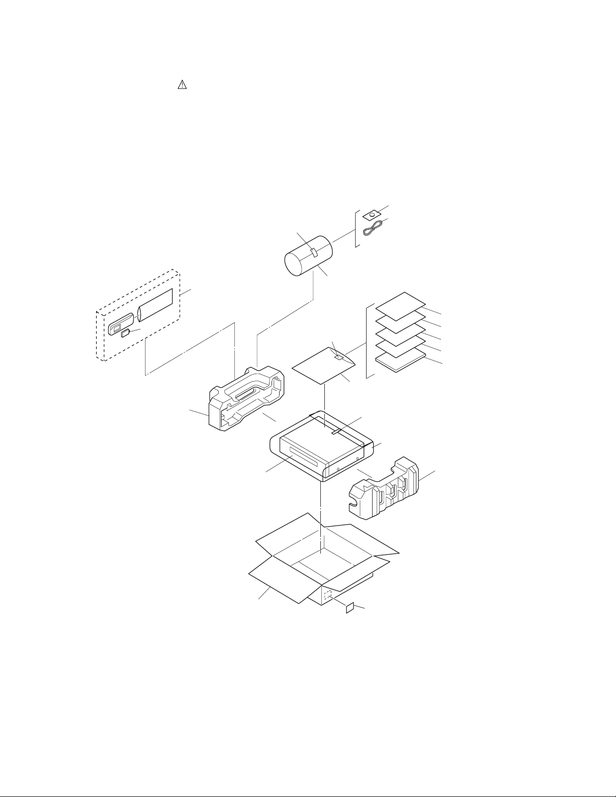
5.1.1 PACKING AND ACCESSORY ASSEMBL Y <M1>
The instruction manual to be provided with this product will differ according to the destination.
309
312
ADHESIVE
TAPE
306A
302
306
FINAL ASSY <M2>
308
ADHESIVE
TAPE
311
ADHESIVE
TAPE
303
318 [ONLY USED FOR UC MODEL]
319 [ONLY USED FOR UC MODEL]
316
320
310
302
301
SPEC OF BARCODE
5-1
Page 2
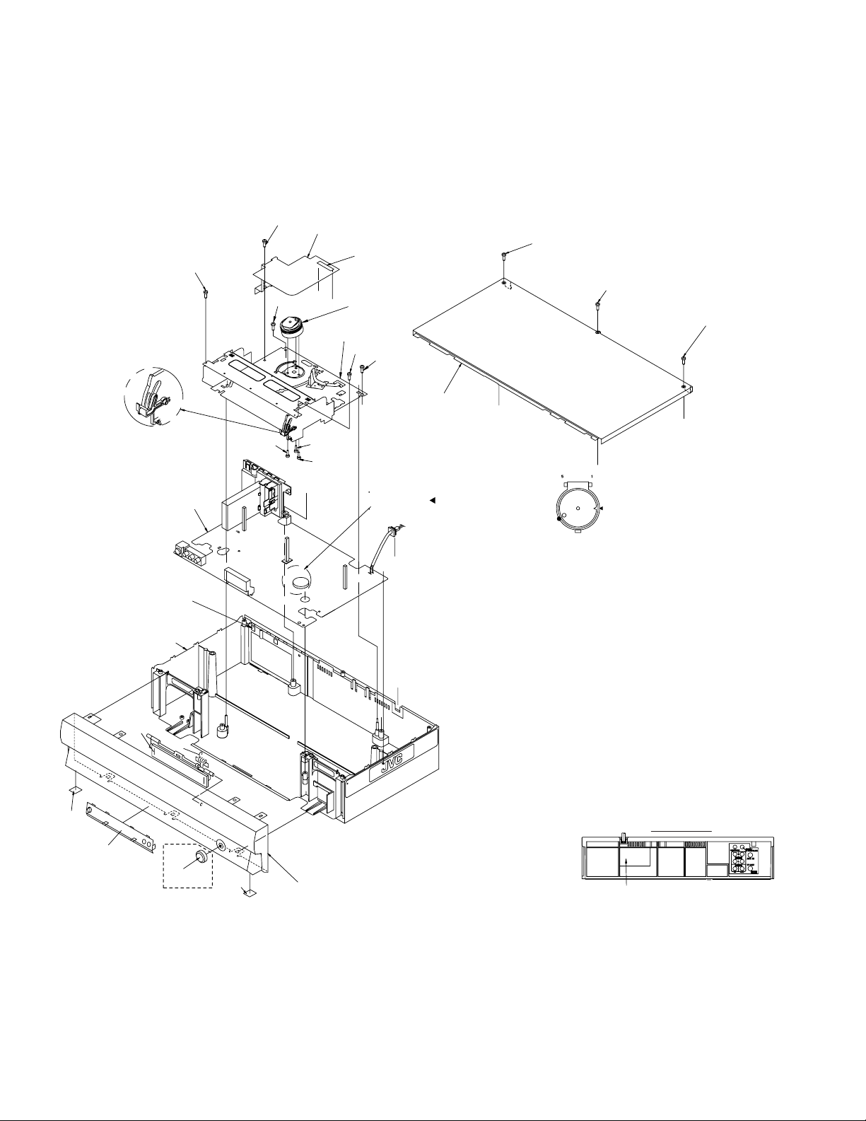
5.1.2 FINAL ASSEMBLY <M2>
BEWARE OF BOGUS PARTS
Parts that do not meet specifications may cause trouble in regard to safety
and performance. We recommend that genuine JVC parts be used.
NOTE)
After screwing,execute the
adjustment inspection of the
tape running.
NOTE)
Confirm the DOOR OPENER is down.
attach the FRONT PANEL after the
CASSETE DOOR is lifted up.
ASSEMBLY<03>
Hang the fook of the TERMINAL BOARD
in hole of CHASSIS.
516
MAIN BOARD
FW
3001
Q3002
510
528
515
b
D3001
JS3001
527
NOTE)
SLOT TO FIT AT THE RIB OF
THE BOTTOM CHASSIS.
505
MECHANISM
ASSEMBLY<M4>
516
b
510
510
b
Q3001
515
502
NOTE)
Hang the hook of the
TOP COVER in hold of
CHASSIS.
NOTE)
Accord the position of V gap on R.ENCORDER
and PWB silk .
Accord the position of Boss on R.ENCORDER
and PWB silk .
Must confirm soldering condition as no
soldering and dry soldering at portion of
Power cord lead on MAIN BOARD before
c
attach MAIN BOARD to BOTTOM CHASSIS.
Check to see the following items, before TOP COVER
is attached.
(1) Wires should not be touched to PRIMARY PARTS
503
and HEAT PARTS easily.
(2) Parts for Insulation should be attached correctly.
503
Before attaching TOP COVER, check to
see the wiring so that the wires should not
be damaged by TOP COVER.
(EX. FLAT WIRE of FRONT BOARD on
JS3001
FRONT PANEL)
503
501E
501C
501A
511
501B
529
NOT USED
z
501E
c
b
z
For the prevention of the DRUM FPC damage.
When you attach the MECHANISM ASSEMBLY on BOTTOM
CHASSIS. Attach the MECHANISM ASSEMBLY after the positioning
boss "Z" of the BOTTOM CHASSIS is matched to the positioning
hole of MECHANISM ASSEMBLY.
501
REAR SIDE
RATING LABEL
5-2
Page 3
WR3
WR1
87
39
1
15
91
86
40
127
128
137
138
138
130
90
89
88
131
75
74
38
105
105
107
31
30
107
112
123
151
113
115
124
125
79
82
21
4
117
44
26
3
58
52
57
58
55
90
37
77
72
116
50
112
122
110
126
126
89
36
73
69
102
70
134
78
76
71
120
42
85
46
47
81
83
80
49
119
53
111
114
118
121
96
93
94
95
64
65
18A
19
22
20
16
23A
63
66
59
62
68
24
18
84
61
60
67
23
23B
18B
WR2
A/C HEAD
BOARD ASSY <12>
LOADING MOTOR
BOARD ASSY <55>
48
AA
AA
AA
AA
AA
AA
AA
AA
AA
AA
AA
AA
AA
BB
BB
BB
BB
BB
AA
AA
AA
AA
AA
AA
AA
AA
AA
AA
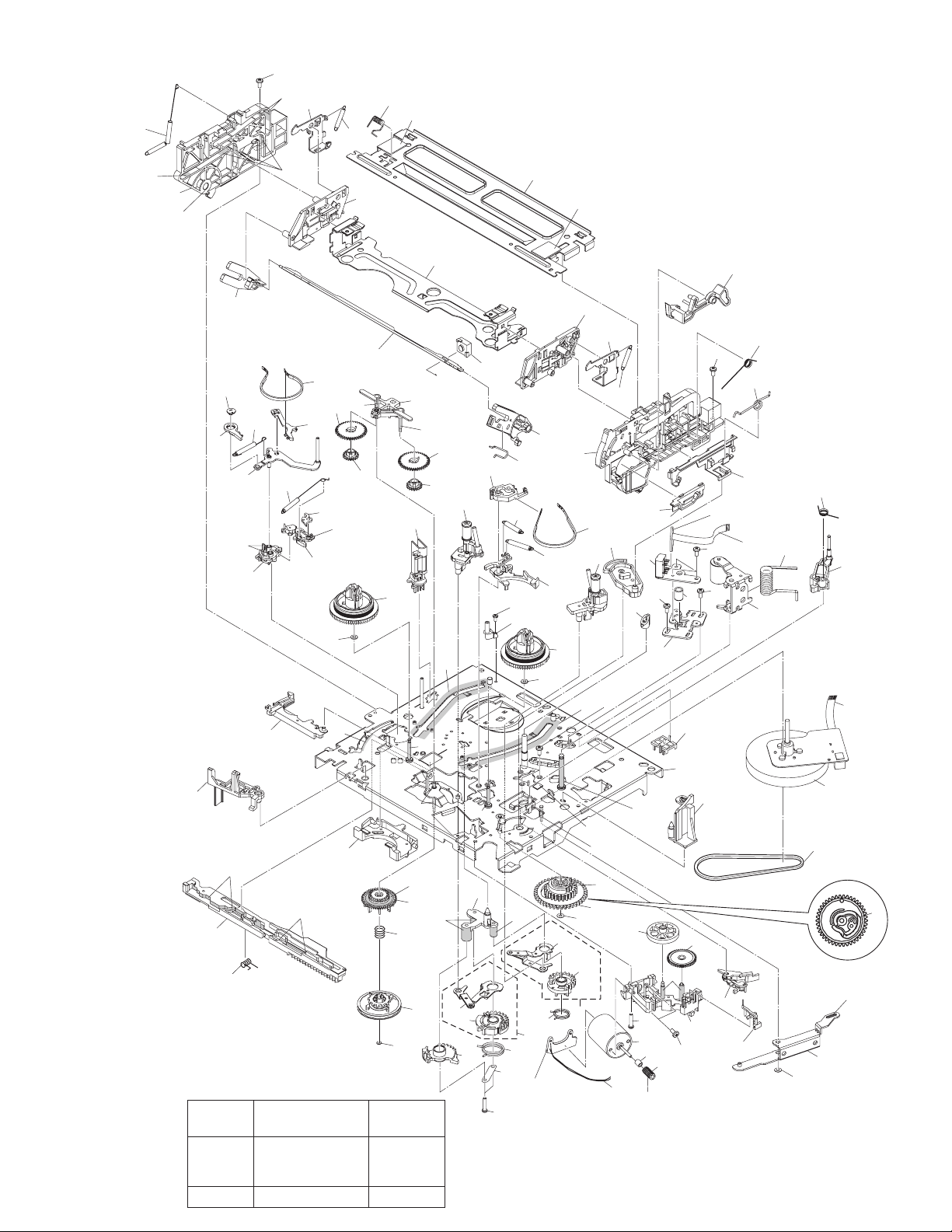
5.1.3 MECHANISM ASSEMBL Y <M4>
Classification drawing
Grease
Part No.
KYODO-SH-P
or
KYODO-SH-JB
Oil COSMO-HV56 BB
Symbol in
AA
NOTE:The section marked in AA and BB
indicate lubrication and greasing areas.
5-3
Page 4

5.2 PARTS LIST
# REF No. PART No. PART NAME, DESCRIPTION # REF No. PART No. PART NAME, DESCRIPTION
--------------- ----------------------- ----------------------------------------------------- ---------------- ----------------------- ------------------------------------------------------
57 LP41036-001A A/C HEAD ADJ. SCREW,X3
******************************
P ACKING AND ACCESSOR Y ASSEMBLY <M1>
301 LP31089-032B PACKING CASE
302 LP31091-001C CUSHION ASSY
303 LP41038-001A POLY BAG
306 LP21138-001C REMOTE CONTROLLER
306A LP40991-001B COVER(BATTERY)
! 309 QAB0057-001 LI BATTERY
! 310 LPT0730-001A INST. BOOK(ENGLISH)
312 PEAC0294-04 RF CABLE
316 BT-51028-2 REGIST.CARD
320 LPT0730-003A SHEET(SETTING)
******************************
FINAL ASSEMBLY <M2>
! 501 LP10464-001C FRONT PANEL ASSY
501A LP21080-008A CASSETTE DOOR
501B PQ46448 TORSION SPRING
501C LP31161-001A WINDOW
501D LP10448-001B COVER
501E PQ43013-7 FOOT,X2
! 502 LP10418-001C TOP COVER
503 QYTDSF3010M SCREW,X3 T OP COVER
505 PDV2542A DRUM ASSY
510 QYSPSPD3008Z SCREW,X3 DRUM
! 511 LP10417-001C BOTTOM CHASSIS
515 QYTDSF4012Z SCREW,X2 BOTTOM-MECHA
516 QYSPSF3010Z SCREW,X2 BOTTOM-C.HOUSING
527 LP21101-001A DRUM SHIELD
528 QYSPST2606Z SCREW,DRUM SHIELD
******************************
MECHANISM ASSEMBL Y <M4>
1 LP21039-001S MAIN DECK ASSY
3 LP40097-002D GUIDE POLE CAP
4 QAH0082-001 FULL ERASE HEAD
15 LP30958-001B LOAD.GEAR BASE
16 QYTPST2620Z SCREW,X2
18 LP40798-001A LORD. GEAR(SUPPLY) ASSY
18A LP21040-001A LORD. GEAR(SUPPLY)
18B LP40799-001A LORD. ARM(SUPPLY) ASSY
19 LP40837-001A TORSION SPRING(SUPPLY)
20 LP40903-001A FIXING PLATE
21 LP40806-001D POLE BASE ASSY(SUPPLY)
22 LP30959-002A LOAD GEAR
23 LP40802-001C LORD. GEAR(TAKE UP) ASSY
23A LP21041-001C LORD. GEAR(TAKE UP)
23B LP40803-001A LORD. ARM(TAKE UP) ASSY
24 LP40838-001A TORSION SPRING(TAKE UP)
36 LP21055-001E TU LEVER
37 LP40943-001A TENSION SPRING
38 LP40859-001D T-UP HEAD
39 LP30961-001C LID GUIDE
42 LP40810-001A PINCH ROLLER ARM ASSY
44 LP40840-001D TORSION SPRING
46 LP30963-001B PRESS LEVER
47 PQM30017-24 SLIT WASHER
48 LP40930-002E S-SWITCH
49 LP40813-001D GIDE ARM ASSY
50 LP40841-001A TORSION SPRING
52 QAH0081-001 AC HEAD
53 LP30965-001A HEAD BASE
55 LP40842-001D COMPRESSION SPRING
58 QYTDST2606Z SCREW ,X2 A/C HEAD-MAIN
59 QAR0023-001 LOADING MOTOR
60 QYTPSP3003Z SCREW,X2 LOADING MOTOR
61 LP21056-002G MOTOR BRACKET
62 QYTPST2620Z SCREW
63 LP40814-001B WORM BEARING
64 LP21044-001D CONTROL CAM
65 PQM30017-24 SLIT WASHER
66 LP40815-001A WORM GEAR
67 LP40816-001B HELICAL GEAR
68 LP40817-001A CONNECT GEAR
69 LP10400-001J CONTROL PLATE
70 LP40843-001A TORSION SPRING
71 LP40818-001B TENSION ARM ASSY
72 LP40844-001E TENSION SPRING
73 LP21045-001D TENSION ARM BASE
74 LP40821-001A TENSION BAND ASSY
75 LP30967-001B BAND HOLDER-1
76 LP30968-001C BAND HOLDER-2
77 LP40822-002B ADJUST PIN
78 LP31000-005E TENSION ARM LEVER
79 LP21046-001C MAIN BRAKE(TAKE UP)
80 LP40824-001A BAND BRAKE ASSY
81 LP30969-002B BRAKE LEVER
82 LP30003-033B TENSION SPRING
83 LP30003-035B TENSION SPRING
84 LP40825-001B CAPSTAN BRAKE ASSY
! 85 QAR0204-002 CAPSTAN MOTOR
86 QYTPSG2606Z SCREW,X3 CAPSTAN MOTOR
87 LP30005-010A BELT,CAPSTAN MOTOR
88 LP30970-001A IDLER ARM
89 LP40828-004A IDLER GEAR 1,X2
90 LP40829-002A IDLER GEAR 2,X2
91 LP31014-001A WIRE HOLDER
93 LP40934-001B CLUTCH UNIT
94 PQM30017-47 SLIT WASHER
95 LP30973-001A DIRECT GEAR
96 LP40939-001A COMPRESS. SPRING
102 LP30974-001B CHANGE LEVER
105 LP21049-001A REEL DISK,X2
107 LP30017-004A SPACER,X2
110 LP10401-001H SIDE FRAME(L)
111 LP10402-001K SIDE FRAME(R)
112 QYTDST2606Z SCREW,X2
113 LP40917-001D TORSION SPRING
114 LP30976-001E SIDE PLATE
115 LP30977-002D LIMIT PLATE
116 LP40846-001C LIMIT SPRING
117 LP31100-001B DRIVE LEVER
118 LP30978-001B DRIVE ARM(L)
119 LP30979-001N DRIVE ARM(R)
120 LP40847-001B TORSION SPRING
121 LP30980-001E CONNECT PLATE
122 LP10403-001C SIDE HOLDER(L)
123 LP10404-001E SIDE HOLDER(R)
124 LP30983-001B LOCK LEVER(L)
125 LP30984-001B LOCK LEVER(R)
126 LP40924-001D TENSION SPRING,X2
127 LP40972-001A EARTH SPRING(1)
128 LP40857-001B EARTH SPRING(2)
130 LP30981-001G CASETTE HOLDER ASSY
134 LP21051-002C REC SAFETY LEVER
137 LP21052-001J TOP FRAME
151 LP30985-001G DOOR OPENER
161 LP40993-001A TAPE GUIDE
WR1 WJT0059-001E E-CARD WIRE,DRUM
WR2 WJT0067-001B E-CARD WIRE,A/C HEAD CN2001
WR3 WJS0022-001A E-FL/RB WIRE,LOADING MOTOR
5-4
Page 5

# REF No. PART No. PART NAME, DESCRIPTION # REF No. PART No. PART NAME, DESCRIPTION
--------------- ----------------------- ----------------------------------------------------- ---------------- ----------------------- ------------------------------------------------------
******************************
MAIN BOARD ASSEMBLY <03>
PW1 LPA10187-01C1 MAIN BOARD ASSY
IC1 JCP8060-NSA IC
IC1 or JCP8060-MSA IC
IC501 JCP8058 IC
or JCP8058-2 IC
IC1201 JCP8057 IC
IC1201 or JCP8036 IC
! IC2201 AN3663FBP IC
IC3001 MN101D06GJL IC
IC3001 or MN101DF06KAFJL IC
IC3004 *(
IC7002 GP1UM291QK IR DETECT UNIT
Q1 DTC144WU DIGI TRANSIST OR
Q1 or PDTC144WU DIGI TRANSISTOR
Q1 or RN1309 DIGI TRANSISTOR
Q1 or UN521E DIGI TRANSISTOR
Q901 2SA1576A/QR/-X TRANSISTOR
Q901 or 2PA1576/R/-X TRANSISTOR
Q902 2SA1576A/QR/-X TRANSISTOR
Q902 or 2PA1576/R/-X TRANSISTOR
Q903 2SA1576A/QR/-X TRANSISTOR
Q903 or 2PA1576/R/-X TRANSISTOR
Q1201 2SC1317/RS/-T TRANSISTOR
Q1205 2SC4081/S/-X TRANSISTOR
Q1205 or2PC4081/R/-X TRANSISTOR
Q1207 2SA1576A/QR/-X TRANSISTOR
Q1207 or2PA1576/R/-X TRANSISTOR
Q2001 2SC4081/QRS/-X TRANSISTOR
Q2001 or2PC4081/R/-X TRANSISTOR
Q2001 or2SD1819A/QRS/-X TRANSISTOR
Q2002 2SC4081/QRS/-X TRANSISTOR
Q2002 or2PC4081/R/-X TRANSISTOR
Q2002 or2SD1819A/QRS/-X TRANSISTOR
Q2003 DTA144WU DIGI TRANSISTOR
Q2003 orPDTA144WU DIGI TRANSISTOR
Q2003 orRN2309 TRANSISTOR
Q2003 orUN511E DIGI TRANSISTOR
Q2051 2SC4081/QRS/-X TRANSISTOR
Q2051 or2SD1819A/QRS/-X TRANSISTOR
Q2051 or2PC4081/R/-X TRANSISTOR
Q2052 2SA1576A/QR/-X TRANSISTOR
Q2052 or2PA1576/R/-X TRANSISTOR
Q2052 or2SB1218A/QR/-X TRANSISTOR
Q2053 DTC144WU DIGI TRANSISTOR
Q2053 orPDTC144WU DIGI TRANSISTOR
Q2053 orRN1309 DIGI TRANSISTOR
Q2053 orUN521E DIGI TRANSISTOR
Q2054 2SA1576A/QR/-X TRANSISTOR
Q2054 or2SB1218A/QR/-X TRANSISTOR
Q2054 or2PA1576/R/-X TRANSISTOR
Q2055 DTC144WU DIGI TRANSISTOR
Q2055 orPDTC144WU DIGI TRANSISTOR
Q2055 orRN1309 DIGI TRANSISTOR
Q2055 orUN521E DIGI TRANSISTOR
Q2201 DTA144WU DIGI TRANSISTOR
Q2201 orPDTA144WU DIGI TRANSISTOR
Q2201 orRN2309 TRANSISTOR
* HR-S2902US : LPN0773-001A-03 The VCR goes to jig RCU mode after replacing the EEPROM and the VCR does not accept some RCU command.
REFER TO BELOW)
IC(EEPROM)
Therefore please set the VCR to the user RCU mode after replacing the EEPROM.
The method of setting the VCR to the user RCU mode is written on the service manual.
Q2201 orUN511E DIGI TRANSISTOR
Q2202 DTC144WU DIGI TRANSISTOR
Q2202 orPDTC144WU DIGI TRANSISTOR
Q2202 orRN1309 DIGI TRANSISTOR
Q2202 orUN521E DIGI TRANSISTOR
Q2203 2SC4081/QRS/-X TRANSISTOR
Q2203 or2SD1819A/QRS/-X TRANSISTOR
Q2203 or2PC4081/R/-X TRANSISTOR
Q2204 2SC4081/QRS/-X TRANSISTOR
Q2204 or2PC4081/R/-X TRANSISTOR
Q2204 or2SD1819A/QRS/-X TRANSISTOR
Q2251 DTC144WU DIGI TRANSISTOR
Q2251 orPDTC144WU DIGI TRANSISTOR
Q2251 orRN1309 DIGI TRANSISTOR
Q2251 orUN521E DIGI TRANSISTOR
Q2252 DTC144WU DIGI TRANSISTOR
Q2252 orPDTC144WU DIGI TRANSISTOR
Q2252 orRN1309 DIGI TRANSISTOR
Q2252 orUN521E DIGI TRANSISTOR
Q2253 DTC144WU DIGI TRANSISTOR
Q2253 orPDTC144WU DIGI TRANSISTOR
Q2253 orRN1309 DIGI TRANSISTOR
Q2253 orUN521E DIGI TRANSISTOR
Q2254 DTC114EU DIGI TRANSISTOR
Q2254 orPDTC114EU DIGI TRANSISTOR
Q2254 orRN1302 DIGI TRANSISTOR
Q2254 orUN5211 DIGI TRANSISTOR
Q3002 PTZ-NV16A IC(PHOTO SENSOR)
Q3006 2SC4081/QRS/-X TRANSISTOR
Q3006 or2SC4081/R/-X TRANSISTOR
Q3007 2SC4081/QRS/-X TRANSISTOR
Q3007 or2SC4081/R/-X TRANSISTOR
Q4001 UN5211 DIGI TRANSISTOR
Q4001 orRN1302 DIGI TRANSISTOR
Q4001 orDTC114EU DIGI TRANSISTOR
Q4001 orPDTC114EU DIGI TRANSISTOR
Q4002 2SD1819A/QRS/-X TRANSISTOR
Q4002 or2PC4081/R/-X TRANSISTOR
Q4002 or2SC4081/QRS/-X TRANSISTOR
! Q5101 2SK2043-CB14 FE TRANSISTOR
! Q5101 or2SK2043 FE TRANSISTOR
Q5102 2SD2144S/UV/-T TRANSISTOR
Q5301 2SC1740S/RS/-T TRANSISTOR
Q5301 or2SC3199/YG/-T TRANSISTOR
Q5303 2SC5739/QP/ TRANSISTOR
Q5304 2SD2144S/UV/-T TRANSISTOR
Q5305 DTA114EU DIGI TRANSISTOR
Q5305 orPDTA114EU DIGI TRANSISTOR
Q5305 orRN2302 TRANSISTOR
Q5305 orUN5111 DIGI TRANSISTOR
Q5306 DTC114EU DIGI TRANSISTOR
Q5306 orPDTC114EU DIGI TRANSISTOR
Q5306 orRN1302 DIGI TRANSISTOR
Q5306 orUN5211 DIGI TRANSISTOR
Q6030 2SB1218A/QR/-X TRANSISTOR
Q6030 or2SA1576A/QR/-X TRANSISTOR
Q6030 or2PA1576/R/-X TRANSISTOR
Q7001 DTA143TU DIGI TRANSISTOR
Q7002 DTA143TU DIGI TRANSISTOR
Q7003 DTA143TU DIGI TRANSISTOR
Q7004 DTA143TU DIGI TRANSISTOR
5-5
Page 6

# REF No. PART No. PART NAME, DESCRIPTION # REF No. PART No. PART NAME, DESCRIPTION
--------------- ----------------------- ----------------------------------------------------- ---------------- ----------------------- ------------------------------------------------------
Q7005 DTA143TU DIGI TRANSISTOR
Q7008 DTC143TU DIGI TRANSISTOR
Q7008 orUN5216 TRANSISTOR
Q7009 DTC143TU DIGI TRANSISTOR
Q7009 orUN5216 TRANSISTOR
Q7010 DTC143TU DIGI TRANSISTOR
Q7010 orUN5216 TRANSISTOR
Q7011 DTC143TU DIGI TRANSISTOR
Q7011 orUN5216 TRANSISTOR
Q7012 DTC143TU DIGI TRANSISTOR
Q7012 orUN5216 TRANSISTOR
Q7013 DTC143TU DIGI TRANSISTOR
Q7013 orUN5216 TRANSISTOR
Q7014 DTC143TU DIGI TRANSISTOR
Q7014 orUN5216 TRANSISTOR
D1 QUY153-050Y IM BUS WIRE
D1201 RD3.9ES/B2/-T2 ZENER DIODE
D1201 or MTZJ3.9B ZENER DIODE
D2001 1SS133 DIODE
D2001 or 1SS270A DIODE
D2251 1SS133 DIODE
D2251 or 1SS270A DIODE
D3001 LNB2301L01VI LE DIODE
D3002 1SS133 DIODE
D3002 or 1SS270A DIODE
D3005 11ES2 DIODE
D3005 or 1A3G DIODE
D3016 MTZJ3.9B ZENER DIODE
D3016 or RD3.9ES/B2/-T2 ZENER DIODE
D5001 S1WB/A/60-4102 BRIDGE DIODE
D5001 or S1WB(A)60F4072X BRIDGE DIODE
D5001 or S1WB/A/60-X BRIDGE DIODE
D5101 AU01 DIODE
D5101 or 10ELS4 FR DIODE
D5102 AU01 DIODE
D5102 or 10ELS4 FR DIODE
D5103 1SS133 DIODE
D5103 or 1SS270A DIODE
D5105 1SS133 DIODE
D5105 or 1SS270A DIODE
D5203 AU01Z FR DIODE
D5203 or 10ELS2 FR DIODE
D5204 AU01Z FR DIODE
D5204 or 10ELS2 FR DIODE
D5206 AW04 SB DIODE
D5206 or AK04 SB DIODE
D5206 or SBO40 SB DIODE
D5206 or 11EQS04 SB DIODE
D5206 or 1S4 SB DIODE
D5207 AW04 SB DIODE
D5207 or SBO40 SB DIODE
D5207 or 1S4 SB DIODE
D5207 or AK04 SB DIODE
D5207 or 11EQS04 SB DIODE
D5210 AU01Z FR DIODE
D5210 or PG104RS FR DIODE
D5210 or 1SR153-400-T2 FR DIODE
D5210 or ERA18-02-T2 FR DIODE
D5210 or 10ELS2 FR DIODE
D5301 MTZJ15C ZENER DIODE
D5301 or RD15ES/B3/-T2 ZENER DIODE
D5302 MTZJ12A ZENER DIODE
D5302 or RD12ES/B1/-T2 ZENER DIODE
D5303 MTZJ5.6A ZENER DIODE
D5303 or RD5.6ES/B1/-T2 ZENER DIODE
D5305 MTZJ5.6C ZENER DIODE
D5305 or RD5.6ES/B3/-T2 ZENER DIODE
D6002 HZ30-2L-T2 ZENER DIODE
D6002 or HZ30-2LTD Z DIODE (M)
R1 NRSA02J-622X MG RESISTOR 6.2kØ,1/10W
R2 NRSA02J-152X MG RESISTOR 1.5kØ,1/10W
R3 NRSA02J-101X MG RESISTOR 100Ø,1/10W
R4 NRSA02J-682X MG RESISTOR 6.8kØ,1/10W
R11 NRSA02J-472X MG RESISTOR 4.7kØ,1/10W
R12 NRSA02J-102X MG RESISTOR 1kØ,1/10W
R14 NRSA02J-182X MG RESISTOR 1.8kØ,1/10W
R19 NCB21HK-103X CAPACITOR 0.01µF,50V
R27 NRSA02J-122X MG RESISTOR 1.2kØ,1/10W
R36 NRSA02J-472X MG RESISTOR 4.7kØ,1/10W
R37 NRSA02J-153X MG RESISTOR 15kØ,1/10W
R201 NRSA02J-332X MG RESISTOR 3.3kØ,1/10W
R202 NRSA02J-222X MG RESISTOR 2.2kØ,1/10W
R501 NRSA02J-221X MG RESISTOR 220Ø,1/10W
R503 NRVA02D-152X CMF RESISTOR 1.5kØ,1/10W
R504 NRVA02D-561X CMF RESISTOR 560Ø,1/10W
R505 NRVA02D-102X CMF RESISTOR 1kØ,1/10W
R506 NRVA02D-392X CMF RESISTOR 3.9kØ,1/10W
R507 NRVA02D-392X CMF RESISTOR 3.9kØ,1/10W
R508 NRVA02D-102X CMF RESISTOR 1kØ,1/10W
R510 NRSA02J-475X MG RESISTOR 4.7MØ,1/10W
R903 NRSA02J-750X MG RESISTOR 75Ø,1/10W
R904 NRSA02J-750X MG RESISTOR 75Ø,1/10W
R905 NRSA02J-750X MG RESISTOR 75Ø,1/10W
R912 NRSA02J-750X MG RESISTOR 75Ø,1/10W
R913 NRSA02J-680X MG RESISTOR 68Ø,1/10W
R915 NRSA02J-750X MG RESISTOR 75Ø,1/10W
R917 QRE123J-331X RESISTOR 330Ø,1/2W
R918 QRE123J-331X RESISTOR 330Ø,1/2W
R919 QRE123J-331X RESISTOR 330Ø,1/2W
R920 NRSA02J-101X MG RESISTOR 100Ø,1/10W
R921 NRSA02J-101X MG RESISTOR 100Ø,1/10W
R1201 NRSA02J-121X MG RESISTOR 120Ø,1/10W
R1202 NRSA02J-101X MG RESISTOR 100Ø,1/10W
R1203 QRE141J-102Y RESISTOR 1kØ,1/4W
R1204 QRE141J-102Y RESISTOR 1kØ,1/4W
R1205 QRE141J-102Y RESISTOR 1kØ,1/4W
R1206 QRE141J-561Y RESISTOR 560Ø,1/4W
R1207 NRSA02J-562X MG RESISTOR 5.6kØ,1/10W
R1208 NRSA02J-123X MG RESISTOR 12kØ,1/10W
R1209 NRSA02J-180X MG RESISTOR 18Ø,1/10W
R1210 NRVA02D-393X CMF RESISTOR 39kØ,1/10W
R1211 NRVA02D-183X CMF RESISTOR 18kØ,1/10W
R1214 NRSA02J-750X MG RESISTOR 75Ø,1/10W
R1217 NRVA02D-680X CMF RESISTOR 68Ø,1/10W
R1218 NRVA02D-301X CMF RESISTOR 300Ø,1/10W
R1220 QRE141J-561Y RESISTOR 560Ø,1/4W
R1223 NRSA02J-0R0X MG RESISTOR 0Ø,1/10W
R1224 NRSA02J-561X MG RESISTOR 560Ø,1/10W
R1229 NRSA02J-222X MG RESISTOR 2.2kØ,1/10W
R1230 NRSA02J-152X MG RESISTOR 1.5kØ,1/10W
R1231 QRE141J-101Y RESISTOR 100Ø,1/4W
R2003 NRSA02J-101X MG RESISTOR 100Ø,1/10W
5-6
Page 7

# REF No. PART No. PART NAME, DESCRIPTION # REF No. PART No. PART NAME, DESCRIPTION
--------------- ----------------------- ----------------------------------------------------- ---------------- ----------------------- ------------------------------------------------------
R2007 NRSA02J-123X MG RESISTOR 12kØ,1/10W
R2010 NRSA02J-123X MG RESISTOR 12kØ,1/10W
R2013 NRSA02J-123X MG RESISTOR 12kØ,1/10W
R2014 NRSA02J-394X MG RESISTOR 390kØ,1/10W
R2015 NRSA02J-391X MG RESISTOR 390Ø,1/10W
R2016 NRSA02J-473X MG RESISTOR 47kØ,1/10W
R2017 NRSA02J-183X MG RESISTOR 18kØ,1/10W
R2018 NRSA02J-472X MG RESISTOR 4.7kØ,1/10W
R2019 NRSA02J-472X MG RESISTOR 4.7kØ,1/10W
R2021 NRSA02J-333X MG RESISTOR 33kØ,1/10W
R2022 QRE141J-103Y RESISTOR 10kØ,1/4W
R2023 QRE141J-103Y RESISTOR 10kØ,1/4W
R2024 NRSA02J-103X MG RESISTOR 10kØ,1/10W
R2053 NRSA02J-332X MG RESISTOR 3.3kØ,1/10W
R2054 NRSA02J-123X MG RESISTOR 12kØ,1/10W
R2055 NRSA02J-3R3X MG RESISTOR 3.3Ø,1/10W
R2056 QRE141J-820Y RESISTOR 82Ø,1/4W
R2057 NRSA02J-473X MG RESISTOR 47kØ,1/10W
R2058 NRSA02J-183X MG RESISTOR 18kØ,1/10W
R2059 NRSA02J-473X MG RESISTOR 47kØ,1/10W
R2060 NRSA02J-183X MG RESISTOR 18kØ,1/10W
R2201 NRSA02J-473X MG RESISTOR 47kØ,1/10W
R2202 NRSA02J-682X MG RESISTOR 6.8kØ,1/10W
R2205 NRSA02J-473X MG RESISTOR 47kØ,1/10W
R2206 NRSA02J-682X MG RESISTOR 6.8kØ,1/10W
R2209 NRSA02J-101X MG RESISTOR 100Ø,1/10W
R2210 NRSA02J-472X MG RESISTOR 4.7kØ,1/10W
R2211 NRSA02J-332X MG RESISTOR 3.3kØ,1/10W
R2212 NRSA02J-332X MG RESISTOR 3.3kØ,1/10W
R2213 NRSA02J-472X MG RESISTOR 4.7kØ,1/10W
R2214 NRSA02J-101X MG RESISTOR 100Ø,1/10W
R2215 NRSA02J-221X MG RESISTOR 220Ø,1/10W
R2216 NRSA02J-102X MG RESISTOR 1kØ,1/10W
R2217 NRSA02J-472X MG RESISTOR 4.7kØ,1/10W
R2218 NRSA02J-392X MG RESISTOR 3.9kØ,1/10W
R2219 NRSA02J-102X MG RESISTOR 1kØ,1/10W
R2220 NRSA02J-102X MG RESISTOR 1kØ,1/10W
R2230 NRSA02J-102X MG RESISTOR 1kØ,1/10W
R2231 NRSA02J-102X MG RESISTOR 1kØ,1/10W
R2251 NRSA02J-472X MG RESISTOR 4.7kØ,1/10W
R2252 NRSA02J-332X MG RESISTOR 3.3kØ,1/10W
R2253 NRSA02J-101X MG RESISTOR 100Ø,1/10W
R2254 NRSA02J-103X MG RESISTOR 10kØ,1/10W
R2255 QRE141J-273Y RESISTOR 27kØ,1/4W
R2256 NRSA02J-222X MG RESISTOR 2.2kØ,1/10W
R2257 NRSA02J-684X MG RESISTOR 680kØ,1/10W
R2258 NRSA02J-0R0X MG RESISTOR 0Ø,1/10W
R3005 QRE141J-102Y RESISTOR 1kØ,1/4W
R3006 QUY160-100Y IM BUS WIRE
R3007 QUY160-100Y IM BUS WIRE
R3008 QUY160-100Y IM BUS WIRE
R3009 QUY160-100Y IM BUS WIRE
R3010 QUY160-100Y IM BUS WIRE
R3011 QUY160-100Y IM BUS WIRE
R3012 QUY160-100Y IM BUS WIRE
R3015 QUY153-050Y IM BUS WIRE
R3017 NRSA02J-471X MG RESISTOR 470Ø,1/10W
R3018 NRSA02J-471X MG RESISTOR 470Ø,1/10W
R3021 NRSA02J-102X MG RESISTOR 1kØ,1/10W
R3022 NRSA02J-102X MG RESISTOR 1kØ,1/10W
R3031 NRSA02J-102X MG RESISTOR 1kØ,1/10W
R3032 NRSA02J-102X MG RESISTOR 1kØ,1/10W
R3035 NRSA02J-0R0X MG RESISTOR 0Ø,1/10W
R3043 NRSA02J-0R0X MG RESISTOR 0Ø,1/10W
R3058 NRSA02J-102X MG RESISTOR 1kØ,1/10W
R3060 NRSA02J-102X MG RESISTOR 1kØ,1/10W
R3064 QRE141J-102Y RESISTOR 1kØ,1/4W
R3066 NRSA02J-0R0X MG RESISTOR 0Ø,1/10W
R3086 QUY160-100Y IM BUS WIRE
R3087 QUY160-100Y IM BUS WIRE
R3088 QUY160-100Y IM BUS WIRE
R3089 QUY160-100Y IM BUS WIRE
R3091 NRSA02J-472X MG RESISTOR 4.7kØ,1/10W
R3092 NRSA02J-472X MG RESISTOR 4.7kØ,1/10W
R3093 NRSA02J-472X MG RESISTOR 4.7kØ,1/10W
R3094 NRSA02J-472X MG RESISTOR 4.7kØ,1/10W
R3095 QUY160-100Y IM BUS WIRE
R3096 QUY160-100Y IM BUS WIRE
R3097 QUY160-100Y IM BUS WIRE
R3098 QUY160-100Y IM BUS WIRE
R3099 QUY160-100Y IM BUS WIRE
R3205 NRSA02J-103X MG RESISTOR 10kØ,1/10W
R3206 NRSA02J-103X MG RESISTOR 10kØ,1/10W
R3207 NRSA02J-103X MG RESISTOR 10kØ,1/10W
R3208 NRSA02J-103X MG RESISTOR 10kØ,1/10W
R3209 NRSA02J-181X MG RESISTOR 180Ø,1/10W
R3211 NRSA02J-183X MG RESISTOR 18kØ,1/10W
R3212 NRSA02J-121X MG RESISTOR 120Ø,1/10W
R3213 NRSA02J-183X MG RESISTOR 18kØ,1/10W
R3214 NRSA02J-121X MG RESISTOR 120Ø,1/10W
R3215 NRSA02J-183X MG RESISTOR 18kØ,1/10W
R3216 NRSA02J-474X MG RESISTOR 470kØ,1/10W
R3217 NRSA02J-334X MG RESISTOR 330kØ,1/10W
R3218 NRSA02J-103X MG RESISTOR 10kØ,1/10W
R3219 NRSA02J-103X MG RESISTOR 10kØ,1/10W
R3220 NRSA02J-562X MG RESISTOR 5.6kØ,1/10W
R3222 NRSA02J-471X MG RESISTOR 470Ø,1/10W
R3223 NRSA02J-105X MG RESISTOR 1MØ,1/10W
R3224 NRSA02J-101X MG RESISTOR 100Ø,1/10W
R3226 NRSA02J-472X MG RESISTOR 4.7kØ,1/10W
R3227 NRSA02J-472X MG RESISTOR 4.7kØ,1/10W
R3237 NRSA02J-472X MG RESISTOR 4.7kØ,1/10W
R3238 NRSA02J-472X MG RESISTOR 4.7kØ,1/10W
R3242 NRSA02J-103X MG RESISTOR 10kØ,1/10W
R3243 NRSA02J-681X MG RESISTOR 680Ø,1/10W
R3244 NRSA02J-331X MG RESISTOR 330Ø,1/10W
R3245 NRSA02J-682X MG RESISTOR 6.8kØ,1/10W
R3252 QRE141J-153Y RESISTOR 15kØ,1/4W
R3253 QRE141J-103Y RESISTOR 10kØ,1/4W
R4001 NRSA02J-222X MG RESISTOR 2.2kØ,1/10W
R4002 NRSA02J-562X MG RESISTOR 5.6kØ,1/10W
R4003 NRSA02J-0R0X MG RESISTOR 0Ø,1/10W
R4010 NRSA02J-471X MG RESISTOR 470Ø,1/10W
R4011 NRSA02J-471X MG RESISTOR 470Ø,1/10W
R4012 NRSA02J-153X MG RESISTOR 15kØ,1/10W
R4018 NRSA02J-102X MG RESISTOR 1kØ,1/10W
R4019 NRSA02J-102X MG RESISTOR 1kØ,1/10W
! R5001 QRZ9046-475Z RESISTOR 4.7MØ,1/2W
R5101 QRE141J-334Y RESISTOR 330kØ,1/4W
R5102 QRE141J-334Y RESISTOR 330kØ,1/4W
R5103 QRE141J-683Y RESISTOR 68kØ,1/4W
R5104 QRG029J-154G OMF RESISTOR 150kØ,2W
5-7
Page 8

# REF No. PART No. PART NAME, DESCRIPTION # REF No. PART No. PART NAME, DESCRIPTION
--------------- ----------------------- ----------------------------------------------------- ---------------- ----------------------- ------------------------------------------------------
R5106 QRT01DJ-R39X MF RESISTOR 0.39Ø,1W
R5107 QRE121J-331Y RESISTOR 330Ø,1/2W
R5108 NRSA02J-122X MG RESISTOR 1.2kØ,1/10W
R5109 QRE141J-681Y RESISTOR 680Ø,1/4W
R5110 NRSA02J-224X MG RESISTOR 220kØ,1/10W
R5112 NRSA02J-221X MG RESISTOR 220Ø,1/10W
R5302 NRSA02J-102X MG RESISTOR 1kØ,1/10W
R5303 NRSA02J-122X MG RESISTOR 1.2kØ,1/10W
R5304 NRSA02J-471X MG RESISTOR 470Ø,1/10W
R5306 QRE141J-181Y RESISTOR 180Ø,1/4W
R5310 NRSA02J-103X MG RESISTOR 10kØ,1/10W
R5312 NRSA02J-102X MG RESISTOR 1kØ,1/10W
R5313 NRSA02J-821X MG RESISTOR 820Ø,1/10W
R6020 NRSA02J-102X MG RESISTOR 1kØ,1/10W
R6021 NRSA02J-102X MG RESISTOR 1kØ,1/10W
R6030 NRSA02J-332X MG RESISTOR 3.3kØ,1/10W
R6031 NRSA02J-101X MG RESISTOR 100Ø,1/10W
R6050 QRE141J-330Y RESISTOR 33Ø,1/4W
R6051 QRE141J-102Y RESISTOR 1kØ,1/4W
R6056 NRSA02J-0R0X MG RESISTOR 0Ø,1/10W
R6502 NRSA02J-332X MG RESISTOR 3.3kØ,1/10W
R7002 NRSA02J-331X MG RESISTOR 330Ø,1/10W
R7003 NRSA02J-331X MG RESISTOR 330Ø,1/10W
R7004 NRSA02J-331X MG RESISTOR 330Ø,1/10W
R7005 NRSA02J-331X MG RESISTOR 330Ø,1/10W
R7006 NRSA02J-331X MG RESISTOR 330Ø,1/10W
R7007 NRSA02J-331X MG RESISTOR 330Ø,1/10W
R7008 NRSA02J-331X MG RESISTOR 330Ø,1/10W
R7015 NRSA02J-0R0X MG RESISTOR 0Ø,1/10W
R7020 NRSA02J-103X MG RESISTOR 10kØ,1/10W
R7021 NRSA02J-122X MG RESISTOR 1.2kØ,1/10W
R7022 NRSA02J-182X MG RESISTOR 1.8kØ,1/10W
R7023 NRSA02J-222X MG RESISTOR 2.2kØ,1/10W
R7024 NRSA02J-272X MG RESISTOR 2.7kØ,1/10W
R7030 NRSA02J-103X MG RESISTOR 10kØ,1/10W
R7031 NRSA02J-122X MG RESISTOR 1.2kØ,1/10W
R7032 NRSA02J-182X MG RESISTOR 1.8kØ,1/10W
R7033 NRSA02J-222X MG RESISTOR 2.2kØ,1/10W
VR2251 QRE141J-103Y RESISTOR 10kØ,1/4W
B1 NRSA02J-0R0X MG RESISTOR 0Ø,1/10W
B3 NRSA02J-0R0X MG RESISTOR 0Ø,1/10W
B4 NRSA02J-0R0X MG RESISTOR 0Ø,1/10W
B6 NRSA02J-0R0X MG RESISTOR 0Ø,1/10W
B501 QUY160-160Y IM BUS WIRE
B503 NRSA02J-0R0X MG RESISTOR 0Ø,1/10W
B903 QUY160-060Y IM BUS WIRE
B906 NRSA02J-0R0X MG RESISTOR 0Ø,1/10W
B1201 NRSA02J-0R0X MG RESISTOR 0Ø,1/10W
B1202 NRSA02J-0R0X MG RESISTOR 0Ø,1/10W
B1203 NRSA02J-0R0X MG RESISTOR 0Ø,1/10W
B2051 NRSA02J-0R0X MG RESISTOR 0Ø,1/10W
B3001 NRSA02J-0R0X MG RESISTOR 0Ø,1/10W
B5302 NRSA02J-0R0X MG RESISTOR 0Ø,1/10W
B6020 QUY160-220Y IM BUS WIRE
B6531 NRSA02J-0R0X MG RESISTOR 0Ø,1/10W
B7001 NRSA02J-0R0X MG RESISTOR 0Ø,1/10W
C1 NDC21HJ-151X CAPACITOR 150pF,50V
C2 NDC21HJ-4R0X CAPACITOR 4pF,50V
C3 NDC21HJ-470X CAPACITOR 47pF,50V
C4 QEKJ1EM-106 E CAPACITOR 10µF,25V
C5 NCB21HK-103X CAPACITOR 0.01µF,50V
C6 NCB21EK-104X CAPACITOR 0.1µF,25V
C7 NCB21EK-104X CAPACITOR 0.1µF,25V
C8 NCB21HK-103X CAPACITOR 0.01µF,50V
C9 QEKJ1HM-225 E CAPACITOR 2.2µF,50V
C10 QEKJ0JM-476 E CAPACITOR 47µF,6.3V
C11 QEKJ1HM-105 E CAPACITOR 1µF,50V
C13 QEKJ1HM-105 E CAPACITOR 1µF,50V
C14 QEKJ1HM-105 E CAPACITOR 1µF,50V
C15 NCB21EK-104X CAPACITOR 0.1µF,25V
C16 NCB21HK-103X CAPACITOR 0.01µF,50V
C18 NCB21EK-104X CAPACITOR 0.1µF,25V
C19 NCB21EK-104X CAPACITOR 0.1µF,25V
C20 NCB21EK-104X CAPACITOR 0.1µF,25V
C21 NCB21HK-103X CAPACITOR 0.01µF,50V
C23 NCB21EK-104X CAPACITOR 0.1µF,25V
C24 NCB21EK-104X CAPACITOR 0.1µF,25V
C25 QEKJ1HM-335 E CAPACITOR 3.3µF,50V
C26 QEKJ1EM-106 E CAPACITOR 10µF,25V
C27 NCB21HK-103X CAPACITOR 0.01µF,50V
C30 NCB21HK-331X CAPACITOR 330pF,50V
C31 QEKJ0JM-476 E CAPACITOR 47µF,6.3V
C32 QCBB1HK-104 CAPACITOR 0.1µF,50V
C33 QEKJ1EM-106 E CAPACITOR 10µF,25V
C34 NCB21HK-103X CAPACITOR 0.01µF,50V
C35 NCB21HK-103X CAPACITOR 0.01µF,50V
C36 QEKJ1HM-105 E CAPACITOR 1µF,50V
C37 NDC21HJ-4R0X CAPACITOR 4pF,50V
C38 NCB21HK-103X CAPACITOR 0.01µF,50V
C39 QEKJ0JM-476 E CAPACITOR 47µF,6.3V
C40 NCB21HK-103X CAPACITOR 0.01µF,50V
C41 NCB21EK-104X CAPACITOR 0.1µF,25V
C43 QEKJ1HM-335 E CAPACITOR 3.3µF,50V
C44 QEKJ1HM-225 E CAPACITOR 2.2µF,50V
C45 NCB21HK-472X CAPACITOR 0.0047µF,50V
C46 NCB21EK-104X CAPACITOR 0.1µF,25V
C47 QEKJ1HM-474 E CAPACITOR 0.47µF,50V
C48 NCB21EK-223X CAPACITOR 0.022µF,25V
C49 QEKJ1HM-475 E CAPACITOR 4.7µF,50V
C50 NCB21HK-103X CAPACITOR 0.01µF,50V
C52 NDC21HJ-150X CAPACITOR 15pF,50V
C56 NCB21EK-104X CAPACITOR 0.1µF,25V
C57 NCF21EZ-104X CAPACITOR 0.1µF,25V
C58 NCF21EZ-104X CAPACITOR 0.1µF,25V
C59 NCF21EZ-104X CAPACITOR 0.1µF,25V
C60 NCF21EZ-104X CAPACITOR 0.1µF,25V
C61 QEKJ0JM-476 E CAPACITOR 47µF,6.3V
C62 QCBB1HK-103 CAPACITOR 0.01µF,50V
C63 NRSA02J-0R0X MG RESISTOR 0Ø,1/10W
C64 NRSA02J-0R0X MG RESISTOR 0Ø,1/10W
C201 QERF0JM-476 E CAPACITOR 47µF,6.3V
C203 NCF21CZ-105X CAPACITOR 1µF,16V
C205 NDC21HJ-101X CAPACITOR 100pF,50V
C207 NCF21CZ-105X CAPACITOR 1µF,16V
C501 QEKJ0JM-476 E CAPACITOR 47µF,6.3V
C502 NCB21HK-103X CAPACITOR 0.01µF,50V
C503 QEKJ1HM-225 E CAPACITOR 2.2µF,50V
C504 QEKJ1HM-225 E CAPACITOR 2.2µF,50V
C507 QCBB1HK-103 CAPACITOR 0.01µF,50V
C508 NCB21HK-104X CAPACITOR 0.1µF,50V
C509 NCB21HK-103X CAPACITOR 0.01µF,50V
C510 QCBB1HK-103 CAPACITOR 0.01µF,50V
5-8
Page 9

# REF No. PART No. PART NAME, DESCRIPTION # REF No. PART No. PART NAME, DESCRIPTION
--------------- ----------------------- ----------------------------------------------------- ---------------- ----------------------- ------------------------------------------------------
C511 QEKJ0JM-337 E CAPACITOR 330µF,6.3V
C513 NDC21HJ-221X CAPACITOR 220pF,50V
C514 NDC21HG-271X CAPACITOR 270pF,50V
C515 NDC21HJ-121X CAPACITOR 120pF,50V
C516 NDC21HG-271X CAPACITOR 270pF,50V
C517 QEKJ1HM-475 E CAPACITOR 4.7µF,50V
C518 QEKJ1HM-225 E CAPACITOR 2.2µF,50V
C519 NDC21HG-271X CAPACITOR 270pF,50V
C520 QEKJ1HM-225 E CAPACITOR 2.2µF,50V
C521 NCB21HK-103X CAPACITOR 0.01µF,50V
C522 QEKJ1HM-475 E CAPACITOR 4.7µF,50V
C523 QCBB1HK-103 CAPACITOR 0.01µF,50V
C524 QEKJ1EM-106 E CAPACITOR 10µF,25V
C525 QCBB1HK-103 CAPACITOR 0.01µF,50V
C528 NCB21EK-104X CAPACITOR 0.1µF,25V
C529 NCB21HK-103X CAPACITOR 0.01µF,50V
C530 NCB21HK-103X CAPACITOR 0.01µF,50V
C537 NDC21HJ-5R0X CAPACITOR 5pF,50V
C539 QCBB1HK-103 CAPACITOR 0.01µF,50V
C922 NCB21HK-103X CAPACITOR 0.01µF,50V
C923 QETN0JM-477 E CAPACITOR 470µF,6.3V
C924 QETN0JM-477 E CAPACITOR 470µF,6.3V
C926 NCB21HK-103X CAPACITOR 0.01µF,50V
C1201 QEKJ0JM-476 E CAPACITOR 47µF,6.3V
C1204 NDC21HJ-101X CAPACITOR 100pF,50V
C1211 QEKJ0JM-476 E CAPACITOR 47µF,6.3V
C1212 NCB21HK-102X CAPACITOR 0.001µF,50V
C1213 NCF21EZ-104X CAPACITOR 0.1µF,25V
C1214 NCF21CZ-105X CAPACITOR 1µF,16V
C1215 QEKJ0JM-476 E CAPACITOR 47µF,6.3V
C1216 NCF21EZ-104X CAPACITOR 0.1µF,25V
C1217 NCF21EZ-104X CAPACITOR 0.1µF,25V
C1218 NCF21EZ-104X CAPACITOR 0.1µF,25V
C1219 NCF21CZ-105X CAPACITOR 1µF,16V
C1220 QEKJ0JM-476 E CAPACITOR 47µF,6.3V
C1227 NCB21EK-104X CAPACITOR 0.1µF,25V
C1228 QEKJ1EM-475 E CAPACITOR 4.7µF,25V
C1229 NCB21HK-103X CAPACITOR 0.01µF,50V
C1230 NCF21EZ-104X CAPACITOR 0.1µF,25V
C1231 NCF21EZ-104X CAPACITOR 0.1µF,25V
C1232 NCF21EZ-104X CAPACITOR 0.1µF,25V
C1233 NCB21HK-103X CAPACITOR 0.01µF,50V
C1234 NCF21EZ-104X CAPACITOR 0.1µF,25V
C1235 QEKJ0JM-476 E CAPACITOR 47µF,6.3V
C1236 NCF21EZ-104X CAPACITOR 0.1µF,25V
C1237 NCF21EZ-104X CAPACITOR 0.1µF,25V
C1243 NCB21HK-103X CAPACITOR 0.01µF,50V
C1244 QEKC1EM-475 E CAPACITOR 4.7µF,25V
C1246 QEKJ0JM-476 E CAPACITOR 47µF,6.3V
C1249 NDC21HJ-470X CAPACITOR 47pF,50V
C2001 QEKJ1HM-475 E CAPACITOR 4.7µF,50V
C2002 QEKJ1HM-105 E CAPACITOR 1µF,50V
C2003 QEKJ0JM-476 E CAPACITOR 47µF,6.3V
C2004 NCB21HK-103X CAPACITOR 0.01µF,50V
C2005 QEKJ1HM-475 E CAPACITOR 4.7µF,50V
C2006 NCB21HK-682X CAPACITOR 0.0068µF,50V
C2007 QEKJ1CM-226 E CAPACITOR 22µF,16V
C2008 QEKJ1HM-475 E CAPACITOR 4.7µF,50V
C2009 NCB21HK-152X CAPACITOR 0.0015µF,50V
C2010 NCB21HK-821X CAPACITOR 820pF,50V
C2011 QEKJ1HM-475 E CAPACITOR 4.7µF,50V
C2012 QEKJ1HM-475 E CAPACITOR 4.7µF,50V
C2051 NCB21HK-331X CAPACITOR 330pF,50V
C2053 NCB21HK-472X CAPACITOR 0.0047µF,50V
C2054 NCB21HK-223X CAPACITOR 0.022µF,50V
C2055 QEKJ1EM-106 E CAPACITOR 10µF,25V
C2065 QFN31HJ-823 F CAPACITOR 0.082µF,50V
C2201 QEKJ1EM-106 E CAPACITOR 10µF,25V
C2202 QEKJ1HM-475 E CAPACITOR 4.7µF,50V
C2203 QEKJ1HM-475 E CAPACITOR 4.7µF,50V
C2204 QEKJ0JM-336 E CAPACITOR 33µF,6.3V
C2205 QEKJ1EM-106 E CAPACITOR 10µF,25V
C2206 QEKJ1EM-106 E CAPACITOR 10µF,25V
C2207 NCB21HK-153X CAPACITOR 0.015µF,50V
C2208 NCB21HK-153X CAPACITOR 0.015µF,50V
C2209 QEKJ1EM-106 E CAPACITOR 10µF,25V
C2210 QEKJ1EM-106 E CAPACITOR 10µF,25V
C2211 QEKJ0JM-336 E CAPACITOR 33µF,6.3V
C2212 QEKJ0JM-476 E CAPACITOR 47µF,6.3V
C2214 QEKJ1EM-106 E CAPACITOR 10µF,25V
C2215 QEKC1EM-106 E CAPACITOR 10µF,25V
C2216 QEKC1CM-476 E CAPACITOR 47µF,16V
C2218 QEKJ1EM-106 E CAPACITOR 10µF,25V
C2219 QEKJ1CM-226 E CAPACITOR 22µF,16V
C2220 QEKJ1EM-106 E CAPACITOR 10µF,25V
C2221 NCB21EK-223X CAPACITOR 0.022µF,25V
C2222 NCB21HK-103X CAPACITOR 0.01µF,50V
C2230 NDC21HJ-101X CAPACITOR 100pF,50V
C2231 NDC21HJ-101X CAPACITOR 100pF,50V
C2251 QDYB1CN-103Y CAPACITOR 0.01µF,16V
C2252 NCB21HK-103X CAPACITOR 0.01µF,50V
C2253 NCB21HK-103X CAPACITOR 0.01µF,50V
C2254 QEKJ0JM-476 E CAPACITOR 47µF,6.3V
C2255 NCB21HK-103X CAPACITOR 0.01µF,50V
C2256 NCB21HK-103X CAPACITOR 0.01µF,50V
C2257 NCB21HK-103X CAPACITOR 0.01µF,50V
C2259 QEKJ1HM-334 E CAPACITOR 0.33µF,50V
C3011 QEKJ1HM-475 E CAPACITOR 4.7µF,50V
C3016 NDC21HJ-180X CAPACITOR 18pF,50V
C3017 NDC21HJ-220X CAPACITOR 22pF,50V
C3023 NCF21CZ-105X CAPACITOR 1µF,16V
C3035 NCF21EZ-104X CAPACITOR 0.1µF,25V
C3036 QERF0JM-107 E CAPACITOR 100µF,6.3V
C3041 QCBB1HJ-101 CAPACITOR 100pF,50V
C3042 QCBB1HJ-101 CAPACITOR 100pF,50V
C3051 NCF21EZ-104X CAPACITOR 0.1µF,25V
C3052 NCB21HK-103X CAPACITOR 0.01µF,50V
C3071 QETJ1HM-336 E CAPACITOR 33µF,50V
C4001 NCB21EK-104X CAPACITOR 0.1µF,25V
C4002 QERF1HM-105 E CAPACITOR 1µF,50V
C4004 QERF1AM-336 E CAPACITOR 33µF,10V
C4006 NRSA02J-0R0X MG RESISTOR 0Ø,1/10W
C4007 NCB21HK-103X CAPACITOR 0.01µF,50V
C4009 NCB21HK-102X CAPACITOR 0.001µF,50V
C4010 QEKJ0JM-476 E CAPACITOR 47µF,6.3V
C4011 NCB21CK-224X CAPACITOR 0.22µF,16V
C4014 NDC21HJ-101X CAPACITOR 100pF,50V
C4019 NCB21HK-103X CAPACITOR 0.01µF,50V
C4031 QETF1CM-336 E CAPACITOR 33µF,16V
! C5001 QFZ9072-683 F CAPACITOR 0.068µF,250V
! C5004 QCZ9094-472 CAPACITOR 0.0047µF,125V
C5006 QETM2DM-826 E CAPACITOR 82µF,200V
5-9
Page 10

# REF No. PART No. PART NAME, DESCRIPTION # REF No. PART No. PART NAME, DESCRIPTION
--------------- ----------------------- ----------------------------------------------------- ---------------- ----------------------- ------------------------------------------------------
C5101 QCZ0212-472 CAPACITOR 0.0047µF,1kV
C5102 QCZ0339-151Z CAPACITOR 150pF
C5104 QEKJ1HM-105 E CAPACITOR 1µF,50V
C5105 QFN31HJ-183 F CAPACITOR 0.018µF,50V
C5107 QFVF1HJ-104Z F CAPACITOR 0.1µF,50V
C5202 QETN1CM-108 E CAPACITOR 1000µF,16V
C5203 QEMT1AM-128 E CAPACITOR 1200µF,10V
C5204 QETJ2AM-475 E CAPACITOR 4.7µF,100V
C5206 QEKJ1CM-476 E CAPACITOR 47µF,16V
C5207 QEKJ1CM-107 E CAPACITOR 100µF,16V
C5301 QEKJ1CM-107 E CAPACITOR 100µF,16V
C5303 QEKJ1CM-107 E CAPACITOR 100µF,16V
C5305 QFVF1HJ-104Z F CAPACITOR 0.1µF,50V
C6052 NDC21HJ-100X CAPACITOR 10pF,50V
C6056 NDC21HJ-470X CAPACITOR 47pF,50V
C6501 NCB21EK-104X CAPACITOR 0.1µF,25V
C6502 QEKJ1EM-106 E CAPACITOR 10µF,25V
C6503 QEKJ1HM-105 E CAPACITOR 1µF,50V
C6504 NCF21EZ-104X CAPACITOR 0.1µF,25V
C6505 QEKJ1HM-335 E CAPACITOR 3.3µF,50V
C6508 NCB21EK-223X CAPACITOR 0.022µF,25V
C6509 NCB21EK-104X CAPACITOR 0.1µF,25V
C6511 QDYB1CM-103Y CAPACITOR 0.01µF,16V
C6512 NCB21EK-223X CAPACITOR 0.022µF,25V
C6513 QEKJ1HM-225 E CAPACITOR 2.2µF,50V
C6514 NCB21EK-223X CAPACITOR 0.022µF,25V
C6515 QEKC1HM-335 E CAPACITOR 3.3µF,50V
C6516 QEKJ1EM-475 E CAPACITOR 4.7µF,25V
C6517 NCB21CK-224X CAPACITOR 0.22µF,16V
C6532 NCB21HK-104X CAPACITOR 0.1µF,50V
C6533 NRSA02J-0R0X MG RESISTOR 0Ø,1/10W
C7011 QEKJ0JM-476 E CAPACITOR 47µF,6.3V
L1 QQL231J-151Y COIL 150µH
L2 QUY153-050Y IM BUS WIRE
L3 QQL29BJ-100Z COIL 10µH
L5 QQL29BJ-100Z COIL 10µH
! L6 QQL29BJ-100Z COIL 10µH
L7 QQL01BJ-120Z COIL 12µH
L9 QQL231J-100Y COIL 10µH
! L10 QQL29BJ-100Z COIL 10µH
L201 QUY153-050Y IM BUS WIRE
L203 QQL231J-1R0Y COIL 1.0µH
L501 QQL29BJ-101Z COIL 100µH
L502 QQL29BJ-100Z COIL 10µH
L504 QUY153-050Y IM BUS WIRE
L901 QQL29BJ-101Z COIL 100µH
L1202 QQL29BJ-331Z COIL 330µH
L1203 QQL29BJ-101Z COIL 100µH
L1204 QQL29BJ-101Z COIL 100µH
L1205 QUY153-050Y IM BUS WIRE
L1206 QUY153-050Y IM BUS WIRE
L6003 QQL29BK-1R0Z COIL 1.0µH
L6004 QUY153-050Y IM BUS WIRE
L6032 QUY153-050Y IM BUS WIRE
L6050 QQL29BK-1R0Z COIL 1.0µH
L6501 QUY153-050Y IM BUS WIRE
LC1201 QQL29BJ-101Z COIL 1.0µH
X2 QAX0739-001 CRYSTAL RESONATOR
X3001 QAX0526-001 CRYSTAL RESONATOR
S3001 QSW0602-004 PUSH SWITCH,REC SAFETY
S3002 QSW0602-004 PUSH SWITCH,S CASS
S7002 QSW0456-002Z TACT SWITCH,POWER
S7004 QSW0456-002Z TACT SWITCH,REW/CHS7006 QSW0456-002Z TACT SWITCH,FF/CH+
S7008 QSW0456-002Z TACT SWITCH,REC
S7010 QSW0456-002Z TACT SWITCH,PAUSE/CH
S7011 QSW0456-002Z TACT SWITCH,PLAY
S7013 QSW0456-002Z TACT SWITCH,STOP/EJECT
K5101 QQR0678-001Z FERRATE BEADS
K5102 QQR0678-001Z FERRATE BEADS
PC3001 RPI-304J IC(PHOTO SENSOR)
PC3002 RPI-304J IC(PHOTO SENSOR)
! PC5101 PC817X IC(PHOTO COUPLER)
! PC5101or PS2501-1 IC(PHOTO COUPLER)
T2051 PELN0832 OSC TRANSFORMER
! T5001 QQS0186-001 SW TRANSFORMER
! TB1 LP21113-001A TERMINAL BOARD
TU6001 QAU0255-002 TUNER
SD1 LP21126-001A SHIELD CASE(PRE)
SD2 LP31098-001B SHIELD CASE(DEG)
DI7001 LTG-Y2K12M-01J LE DIODE
! CD1 QMPD340-165-K POWER CORD
JS3001 QSW0954-002 ROTARY ENCODER
J2 QNN0530-001 PIN JACK,REAR OUT
J7101 QNN0524-002 PIN JACK,FRONT AV IN
J7103 QND0106-001 S JACK,FRONT S IN
FC5001 QNG0006-001Z FUSE CLIP
FC5002 QNG0006-001Z FUSE CLIP
! LF5002 QQR0532-001 LINE FILTER
! VA5001 QAF0023-431Z VARISTOR
TP106 QUY160-100Y IM BUS WIRE,PB FM
TP111 QUY153-050Y IM BUS WIRE,D FF
TP2253 QUY153-050Y IM BUS WIRE,A.PB
TP2254 QUY153-050Y IM BUS WIRE,A.REC
TP4001 QUY153-050Y IM BUS WIRE,CTL.P
CN1 QGF1201C2-09 FPC CONNECTOR,(1-9)DRUM
CN2001 QGF1207C1-06 FPC CONNECTOR,(1-6)A/C HEAD
CN2002 QGB2532J1-02 B TO B CONNECTOR,(1-2)FE HEAD
CN3001 QGB2032M4-12
B TO B CONNECTOR,(1-12)CAPSTAN MOTOR
CP3001 QUY153-050Y IM BUS WIRE
CP4001 QUY153-050Y IM BUS WIRE
! F5001 QMF51N2-1R25J1 FUSE T1.25A,AC250V
L1207 QQL29BJ-101Z COIL 100µH
L1208 QUY153-050Y IM BUS WIRE
L2001 QUY153-050Y IM BUS WIRE
L2201 QUY153-050Y IM BUS WIRE
L2251 QQL29BJ-100Z COIL 10µH
L4001 QUY153-050Y IM BUS WIRE
L5201 PELN1184 COIL 33µH
L5202 PELN1184 COIL 33µH
L5301 QUY153-050Y IM BUS WIRE
L6001 QQL29BK-1R0Z COIL 1.0µH
5-10
Page 11

# REF No. PART No. PART NAME, DESCRIPTION # REF No. PART No. PART NAME, DESCRIPTION
--------------- ----------------------- ----------------------------------------------------- ---------------- ----------------------- ------------------------------------------------------
******************************
A/C HEAD BOARD ASSEMBLY <12>
PW1 LPA10158-01A1 A/C HEAD BOARD ASSEMBLY
******************************
LOADING MOTOR BOARD ASSEMBLY <55>
PW2 LPA10158-01A2 LOADING MOTOR BOARD ASSY
(VP)-V16S0
5-11
 Loading...