

Page 1
SERVICE MANUAL
VIDEO CASSETTE RECORDER
HR-J3008UM/J4008UM
Regarding service information other than these sections, refer to the HR-A37U service manual (No.82836).
Also, be sure to note important safety precautions provided in the service manual.
SPECIFICATIONS
GENERAL
Power requirement : AC 110 V – 220 Vd, 50 Hz/60 Hz
Power consumption
Power on : 14 W
Power off : 2.0 W
Temperature
Operating : 5°C to 40°C
Storage : –20°C to 60°C
Operating position : Horizontal only
Dimensions (W x H x D) : 360 mm x 94 mm x 247 mm
Weight : 3.0 kg
Format : VHS NTSC standard
Maximum recording time
SP : 210 min. with ST-210 video cassette
EP : 630 min. with ST-210 video cassette
VIDEO/AUDIO
Signal system : NTSC-type color signal and EIA
Recording/Playback
system
Signal-to-noise ratio : 45 dB
Horizontal resolution : 230 lines
Frequency range : 70 Hz to 10,000 Hz
Input/Output : RCA connectors (IN x 1, OUT x 1)
(The specifications shown pertain specifically to the model HR-J4008UM)
monochrome signal, 525 lines/
60 fields
: DA-4 (Double Azimuth) head helical
scan system
TUNER
Tuning system : Frequency-synthesized tuner
Channel coverage
VHF : Channels 2–13
UHF : Channels 14–69
CATV : 113 Channels
RF output : Channel 3 or 4 (switchable; preset to
Channel 3 when shipped) 75 ohms,
unbalanced
TIMER
Clock reference : Quartz
Program capacity : 1-year programmable timer/
8 programs
Memory backup time : Approx. 6 months
Estimated figure based on supplied
fresh battery; actual performance may
differ.
ACCESSORIES
Provided accessories : RF cable (F-type),
Lithium battery CR2025,
Infrared remote control unit,
“AA” battery x 2,
Conversion plug
Specifications shown are for SP mode unless specified otherwise.
E. & O.E. Design and specifications subject to change without
notice.
No.82852
April 2001
Page 2
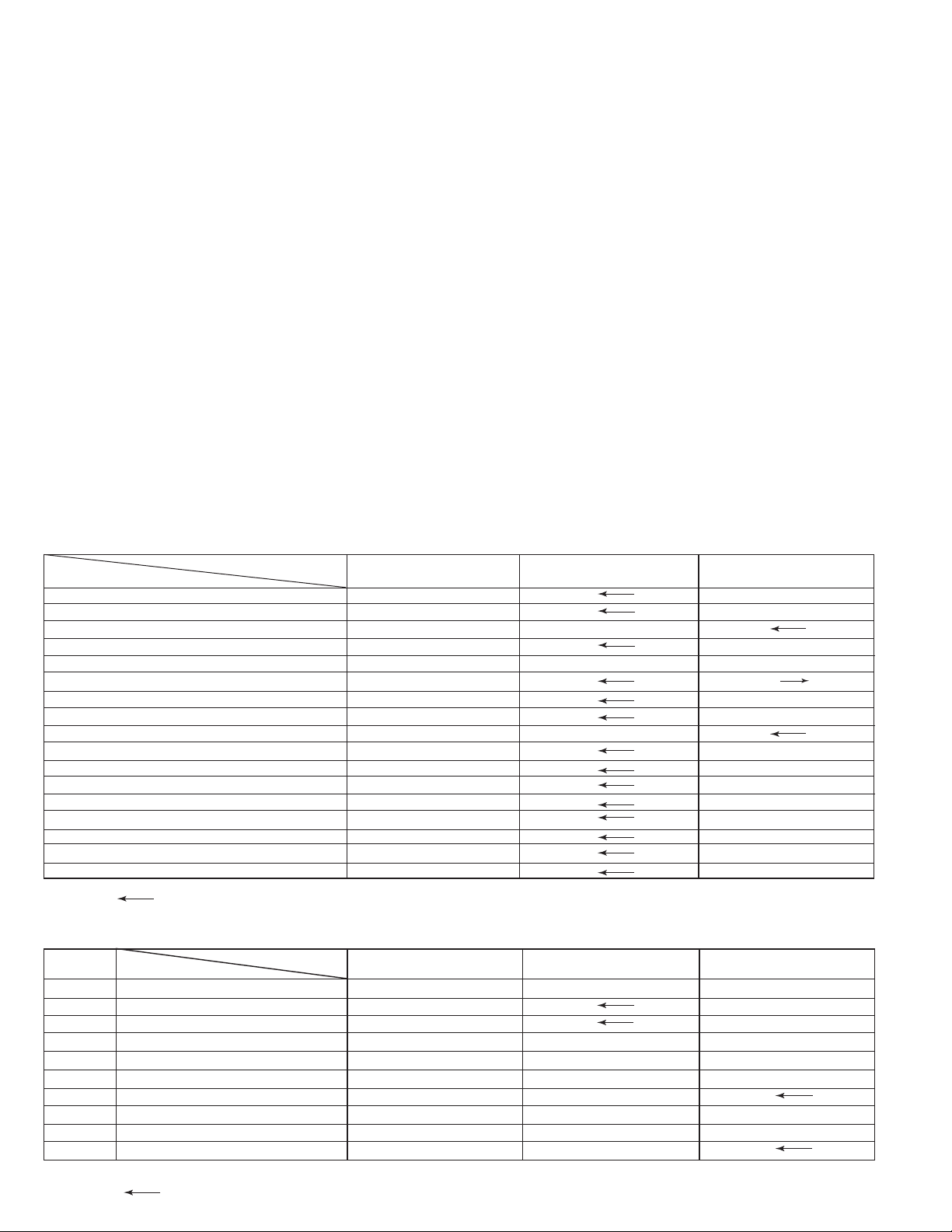
TABLE OF CONTENTS
Section Title Page Section Title Page
DIFFERENT TABLE ........................................................................... 1 to 2
2. MECHANISM ADJUSTMENT
2.1 Before starting repair and adjustment...........................................2-1
2.1.1Precautions ...................................................................................2-1
2.1.2Checking for proper mechanical operations .................................2-1
2.1.3Manually removing the cassette tape ...........................................2-1
2.1.4Jigs and tools required for adjustment ..........................................2-2
2.1.5Maintenance and inspection .........................................................2-3
2.2 Replacement of major parts..........................................................2-6
2.2.1Before starting disassembling
2.2.2How to set the “Mechanism assembling mode” ............................2-6
2.2.3Cassette holder assembly ............................................................2-6
2.2.4Pinch roller arm assembly ............................................................2-8
2.2.5Guide arm assembly and press lever assembly ...........................2-8
2.2.6A/C head .......................................................................................2-8
2.2.7Loading motor ...............................................................................2-8
2.2.8Capstan motor ..............................................................................2-9
2.2.9Pole base assembly (supply or take-up side) ...............................2-9
2.2.10 Rotary encoder .....................................................................2-10
2.2.11 Clutch unit .............................................................................2-10
2.2.12 Change lever assembly,direct gear,clutch gear
2.2.13 Link lever............................................................................... 2-11
2.2.14 Cassette gear,control cam and worm gear ........................... 2-11
2.2.15 Control plate.......................................................................... 2-11
2.2.16 Loading arm gear (supply or take-up side)
2.2.17 Take-up lever,take-up head and control plate guide ............. 2-13
2.2.18 Capstan brake assembly ......................................................2-13
2.2.19 Sub brake assembly (take-up side) ......................................2-13
2.2.20 Main brake assembly (take-up side),
(Phase matching between mechanical parts) .........................2-6
and coupling gear .................................................................2-10
and loading arm gear shaft ................................................... 2-12
2.2.21 Tension brake assembly, reel disk (supply side)
2.2.22 Idler lever, idler arm assembly ..............................................2-14
2.2.23 Stator assembly ....................................................................2-14
2.2.24 Rotor assembly .....................................................................2-14
2.2.25 Upper drum assembly...........................................................2-15
2.3 Compatibility adjustment.............................................................2-16
2.3.1FM waveform linearity .................................................................2-16
2.3.2Height and tilt of the A/C head ....................................................2-17
2.3.3A/C head phase (X-value) ..........................................................2-17
2.3.4Standard tracking preset.............................................................2-18
2.3.5Tension pole position ..................................................................2-18
4. CHARTS AND DIAGRAMS
4.1 MAIN (SYSCOM) AND LT BATTERY
4.2 MAIN CIRCUIT BOARD
4.3 MAIN CIRCUIT BOARD
5. PARTS LIST
5.1 PACKING AND ACCESSORY ASSEMBL Y <M1> ........................ 5-1
5.2 FINAL ASSEMBL Y <M2>.............................................................. 5-2
5.3 MECHANISM ASSEMBLY <M4>.................................................. 5-4
5.4 ELECTRICAL PARTS LIST ..........................................................5-6
reel disk (take-up side) and
main brake assembly (supply side).......................................2-13
and tension arm assembly ....................................................2-14
SCHEMATIC DIAGRAMS.......................................................4-1
(MAIN PWB LPB10130-001C) [HR-J4008UM].............................4-3
(MAIN PWB LPB10130-001D) [HR-J3008UM].............................4-5
MAIN BOARD ASSEMBLY <03> ..................................................5-6
A/C HEAD BOARD ASSEMBLY <12>. .......................................5-10
LOADING MOTOR BOARD ASSEMBLY <55> ..........................5-10
LT BATTERY BOARD ASSEMBLY <93>
[HR-J4008UM] .......................................................................510
The following table indicate main different points between models HR-A37U,HR-J3008UM and HR-J4008UM.
ITEM
MODEL
HR-A37U
HR-J3008UM
HR-J4008UM
POWER VOLTAGE 120V, 60HZ 110-220V, 50/60HZ
POWER PLUG UL, CSA SASO
COSMETIC/COLOR MOLD-DARK GRAY PAINT-Pure SILVER
RCU TYPE / COLOR U1 / MOLD BLACK E1 / PAINT SILVER
INSTRUCTION / LANGUAGE 1 SHEET / ENG YES / SPA YES / SPA, ENG
PLUG ADAPTER NOT USED SASO CEE
LITHIUM BATTERY NOT USED CR2025
HEAD CLEANER NOT USED USED
SHUTTLE SERCH(LATCH) SP
X7, EPX21 SPX7, EPX21(X21)
B.E.S.T. PICTURE AUTO PICTURE A.V. CALIBRATION
AUTO CH PRESET USED (P&P) USED
BACKUP TIME NOT USED 6 MONTHS(LI BATT.)
TIMER PROGRAM BACKUP
PERMANENT PROGRAM
NOT USED
SUMMER TIME ADJUST USED NOT USED
AUTO CLOCK / JUST CLOCK USED NOT USED
REC RESUME NOT USED USED
LANGUAGE[INITIAL] [ENG], SPA, FRE [SPA], ENG
Note: Mark is same as left.
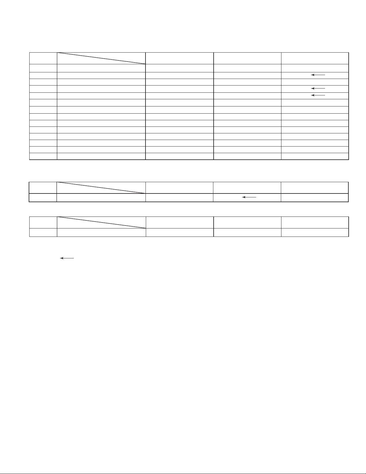
The following table indicate main different points between models HR-A37U,HR-J3008UM and HR-J4008UM.
PACKING AND ACCESSORY ASSEMBLY <M1>
!
REF
NO.
ITEM
MODEL
HR-A37U
HR-J3008UM
HR-J4008UM
301 PACKING CASE LP30836-006A LP30836-017A LP30836-015B
306 REMOTE CONTROL UNIT LP20878-001A
306A COVER(BATTERY) LP40610-001A
LP20878-002A
LP40610-002A
! 309 LITHIUM BATTERY ––– ––– PECA0903
! 310 INST. BOOK(EN) LPT0497-001A ––– LPT0533-001A
! 310 INST. BOOK(SP) ––– LPT0532-001A LPT0533-002A
311 POLY BAG ––– QPC02503530P
! 313 CONVERSION PLUG ––– ––– PEMC1012
317 REGIST. CARD BT-51020-2 ––– –––
320 CONNECTION SHEET ––– PU36560-2
Note: Mark ––– is not used.
Mark is same as left.
1
Page 3
FINAL ASSEMBL Y<M2>
!
REF
NO.
ITEM
MODEL
HR-A37U
HR-J3008UM
HR-J4008UM
! 501 FRONT PANELASSEMBLY * LP10348-004D LP10348-009F LP10348-008F
501A CASSETTE DOOR * LP20977-002C LP20977-008C
501C DISPLAY WINDOW LP20976-004A LP20976-009A LP20976-008A
! 502 TOP COVER LP10352-002A LP10352-008A
503 SCREW,X2,TOP COVER(SIDE) QYTDSF3010M QYTDSF3010R
! 511 BOTTOM CHASSIS * LP10350-003D LP10350-004D LP10350-005D
! 517 POWER CORD ––– ––– QMP73J0-170
518 CLEANER ASSEMBLY ––– ––– LP40369-001D
518A CLEANER ROLLER ––– ––– PQ46418-1-2
518B CLEANER ––– ––– PQ46419-1-2
518C CLEANER ARM ––– ––– LP30407-001D
520 CAP ––– ––– LP30336-001A
531 SCREW,REAR ––– ––– QYTDSF3010M
532 SCREW,TERMINAL BOARD
MAIN BOARD ASSEMBLY<03>
REF
!
NO.
PW1 MAIN BOARD ASSEMBLY * LPA10130-02D1
LITHIUM BATTERY BOARD ASSEMBLY<93>
REF
!
NO.
! PW4
ITEM
ITEM
LITHIUM BATTERY BOARD ASSEMBLY
MODEL
MODEL
––– ––– QYTDSF3010Z
HR-A37U
HR-A37U
––– ––– LPA10130-01A4
HR-J3008UM
HR-J3008UM
HR-J4008UM
LPA10130-05B1
HR-J4008UM
Note : Mark ––– is not used.
Mark
Mark * reference model was also changed.
is same as left.
2
Page 4
SECTION 2
MECHANISM ADJUSTMENT
2.1 Before starting repair and adjustment
2.1.1 Precautions
(1) Unplug the power cord plug of the VCR before using your
soldering iron.
(2) Take care not to cause any damage to the conductor
wires when plugging and unplugging the connectors.
(3) Do not randomly handle the parts without identifying
where the trouble is.
(4) Exercise enough care not to damage the lugs, etc. dur-
ing the repair work.
(5) When reattaching the front panel assembly, make sure
that the door opener of the cassette holder assembly is
lowered in position prior to the reinstallation. (See SECTION 1 DISASSEMBLY.)
(6) When using the Jig RCU, it is required to set the VCR to
the Jig RCU mode (the mode in which codes from the
Jig RCU can be received). (See SECTION 1 DISASSEMBLY.)
Loading motor
2.1.2 Checking for proper mechanical operations
Enter the mechanism service mode when you want to operate the mechanism when no cassette is loaded. (See SECTION 1 DISASSEMBLY.)
2.1.3 Manually removing the cassette tape
1. In case of electrical failures
If you cannot remove the cassette tape which is loaded because of any electrical failure, manually remove it by taking
the following steps.
(1) Unplug the power cord plug from the power outlet.
(2) Refer to the disassembly procedure and perform the dis-
assembly of the major parts before removing the drum
assembly.
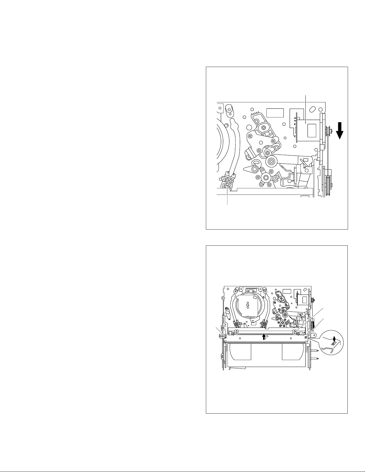
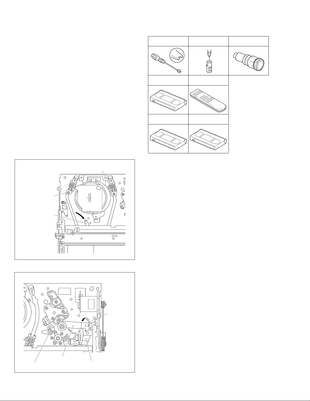
(3) Unload the pole base assembly by manually turning the
loading motor of the mechanism assembly toward the
front. In doing so, hold the tape by the hand to keep the
slack away from any grease. (See Fig.2-1-3a.)
(4) Bring the pole base assembly to a pause when it reaches
the position where it is hidden behind the cassette tape.
(5) Move the top guide toward the drum while holding down
the lug (A) of the bracket retaining the top guide. Likewise hold part (B) down and remove the top guide.
Section (C) of the top guide is then brought under the
cassette lid. Then remove the top guide by pressing the
whole cassette tape down. (See Fig.2-1-3b.)
(6) Remove the cassette tape by holding both the slackened
tape and the cassette lid.
(7) Take up the slack of the tape into the cassette. This com-
pletes removal of the cassette tape.
Note:
• For the disassembly procedure of the major parts and
details of the precautions to be taken, see “SECTION
1 DISASSEMBLY”.
Pole base assembly
Fig. 2-1-3a
(C)
(A)
(B)
Press
Fig. 2-1-3b
2-1
Page 5
2. In case of mechanical failure
If you cannot remove the cassette tape which is loaded because of any mechanical failure, manually remove it by taking the following steps.
(1) Unplug the power cable and remove the top cover, front
panel assembly and others so that the mechanism assembly is visible. (See SECTION 1 DASASSEMBLY.)
(2) While keeping the tension arm assembly of the mecha-
nism assembly free from tension, pull the tape on the pole
base assembly (supply or take-up side) out of the guide
roller. (See Fig.2-1-3c.)
(3) Take the spring of the pinch roller arm assembly off the
hook of the press lever assembly, and detach it from the
tape. (See Fig.2-1-3d.)
(4) In the same way as in the electrical failure instructions in
2.1.3-1(5), remove the top guide.
(5) Raise the cassette tape cover. By keeping it in that posi-
tion, draw out the cassette tape case from the cassette
holder and take out the tape.
(6) By hanging the pinch roller arm assembly spring back
on the hook, take up the slack of the tape into the cassette.
Pole base assembly (take-up side)
2.1.4 Jigs and tools required for adjustment
Roller driver
PTU94002
Back tension cassette gauge
PUJ48076-2
Alignment tape
(SP, stairstep, NTSC)
MHP
A/C head positioning tool
PTU94010
Jig RCU
PTU94023B
Alignment tape
(EP, stairstep, NTSC)
MHP-L
Torque gauge
PUJ48075-2
Pole base assembly
(supply side)
Tension arm assembly
Fig. 2-1-3c
Take the spring
off the hook, and
detach it from the
tape.
Guide pole guard
2-2
Pinch roller arm assembly
Press lever assembly
Fig. 2-1-3d
Page 6
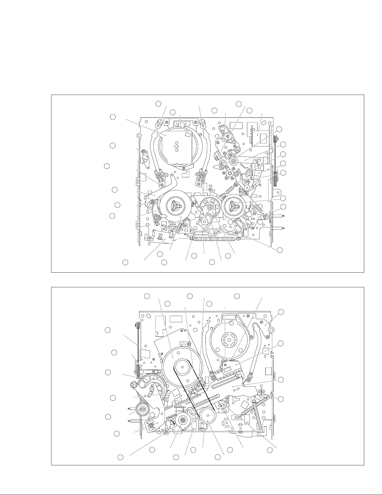
2.1.5 Maintenance and inspection
1. Location of major mechanical parts
In this chapter, the two mechanism speeds are described by comparing the speeds of the standard type and the high-speed
FF/REW type.
It is possible to distinguish between these two types of mechanism by the diameters of their capstan pulleys.
The capstan pulley diameter for the standard type is approx. 32 mm.
The capstan pulley diameter for the high-speed FF/REW type is approx. 43 mm.
For information on the different parts used in the two mechanism types, please refer to the “Replacement of major parts”.
UV catcher2 (supply and take-up side)
Stator assembly
T2
Full erase head
T26
Pole base assembly
T25
(supply side)
Tension arm
T24
assembly
Adjust pin
T23
Tension brake
T22
assembly
T1
T5 T7
T3
Drum assembly
Head base
T6
A/C head
Loading motor
Guide pole guard
T8
Pinch roller arm
T9
assembly
Lid guide
T10
Press lever
T11
assembly
Guide arm
T12
assembly
Reel disk
T13
(take-up side)
Sub brake assembly
T14
(take-up side)
Belt
B22
(loading motor)
B21
Control cam
B20
B19
Cassette gear
B18
Worm gear
Brake lever
Rec safety lever
B1
Reel disk
T20
(supply side)
Main brake assembly
(supply side)
Idler lever
T17T19T21
Idler arm assembly
T16T18
Pole base assembly (take-up side)
Fig. 2-1-5a Mechanism assembly top side
Capstan motor
B2
Capstan brake assembly
B3 B5
Belt (capstan)
Loading arm gear (take-up side)
B4
Loading arm gear (supply side)
Main brake assembly
T15
(take-up side)
Plate
B6
(supply side)
Control
B7
bracket1
Control plate
B8
Tension arm
B9
bearing
Link lever
B17
Rotary encoder guide
B16
Rotary encoder
B15
B14
Direct gear
B13
Change lever assembly
B12
B10
Clutch unit
Take-up head
Fig. 2-1-5b Mechanism assembly bottom side
Take-up lever
B11
2-3
Page 7
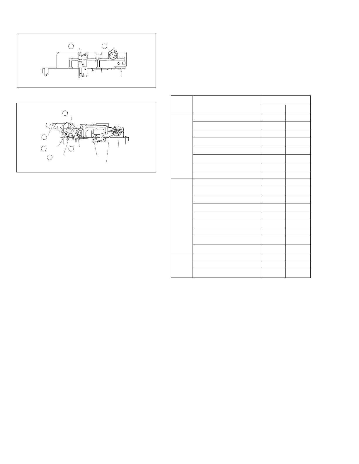
Guide rail Roller cam assembly
L2L1
Fig. 2-1-5c Mechanism assembly left side
R1
Opener guide
Door
R2
opener
Drive gear
R3
Cassette housing bracket
R4
R5
Limit gear
Loading motor
Worm gear
Belt (loading motor)
Fig. 2-1-5d Mechanism assembly right side
2. Cleaning
Regular cleaning of the transport system parts is desirable
but practically impossible. So make it a rule to carry out cleaning of the tape transport system whenever the machine is
serviced.
When the video head, tape guide and/or brush get soiled,
the playback picture may appear inferior or at worst disappear, resulting in possible tape damage.
(1) When cleaning the upper drum (especially the video
head), soak a piece of closely woven cloth or Kimu-wipe
with alcohol and while holding the cloth onto the upper
drum by the fingers, turn the upper drum
counterclockwise.
Note:
• Absolutely avoid sweeping the upper drum vertically
as this will cause damage to the video head.
(2) To clean the parts of the tape transport system other than
the upper drum, use a piece of closely woven cloth or a
cotton swab soaked with alcohol.
(3) After cleaning, make sure that the cleaned parts are com-
pletely dry before using the video tape.
3. Lubrication
With no need for periodical lubrication, you have only to lubricate new parts after replacement. If any oil or grease on
contact parts is soiled, wipe it off and newly lubricate the
parts.
Note:
• See the “mechanism assembly” diagram of the parts
list for the lubricating or greasing spots, and for the
types of oil or grease to be used.
4. Suggested servicing schedule for main components
The following table indicates the suggested period for such
service measures as cleaning,lubrication and replacement.
In practice, the indicated periods will vary widely according
to environmental and usage conditions.However, the indicated components should be inspected when a set is brought
for service and the maintenance work performed if necessary. Also note that rubber parts may deform in time,even if
the set is not used.
System Parts Name
Upper drum assembly
A/C head
Lower drum assembly
Pinch roller arm assembly
Full erase head
Tension arm assembly
Capstan motor (Shaft)
Guide arm assembly
Capstan motor
Capstan brake assembly
Main brake assembly
Belt (Capstan)
Belt (Loading motor)
Loading motor
Clutch unit
Worm gear
Control plate
Brush
Tension brake assembly
Other Drive Tape transport
Rotary encoder
: Cleaning
¤
: Inspection or replacement if necessary
R
Operation Hours
~1000H ~2000H
¤R R
¤R ¤R
¤¤R
¤¤
¤¤
¤¤
¤¤
¤¤
R
R
R
RR
R
R
R
R
R
¤R ¤R
RR
R
Table 2-1-5a
5. Disassembling procedure table
The following table indicates the order in which parts are removed for replacement. To replace parts, remove them in
the order of 1 to 18 as shown in the table. To install them,
reverse the removal sequence.
The symbols and numbers preceding the individual part
names represent the numbers in the “Location of major mechanical parts” table. Also, the “T”, “B”, and “T/B” on the right
of each part name shows that the particular part is removed
from the front, from the back, and from both sides of the
mechanism, respectively.
2-4
Page 8

R4 R1 R3 T9 T12 T11 B15 B12 B14 B13 B17 B21 B7 B8 B5 B4 B11 T14 T15 T13 T22 T24 T18 B1 9
Symbols and numbers
Removal parts
(Reference items)
Replacement parts
Symbols and numbers
2.2.3 Guide rail T 1
L2
2.2.3 Roller cam assembly T 1
R4
2.2.3 Cassette housing bracket T 1
R1
2.2.3 Opener guide T 2
R2
2.2.3 Door opener T 3
2.2.3 Relay gear T 3
R5
2.2.3 Limit gear T 3
2.2.3 Cassette holder assembly T 6
R3
2.2.3 Drive gear T 4
2.2.3 Drive arm T 8
T9
2.2.4 Pinch roller arm assembly T 1
T12
2.2.5 Guide arm assembly T 1
T11
2.2.5 Press lever assembly T 3
T6
2.2.6 A/C head T 1
T7
2.2.7 Loading motor T 1
B1
2.2.8 Capstan motor T/B 1
T1
2.2.9 UV catcher2 T 1
T17
Pole base assembly (take-up side)
2.2.9
T25
Pole base assembly (supply side)
2.2.9
B15
2.2.10 Rotary encoder B 1
B12
2.2.11 Clutch unit B 1
B14
2.2.12 Change lever assembly B 3
B13
2.2.12 Direct gear B 4
2.2.12 Coupling gear B 5
2.2.12 Clutch gear B 6
B17
2.2.13 Link lever B 1
2.2.14 Cassette gear B 2
B18
B20
2.2.14 Control cam B 2
B21
2.2.14 Worm gear B 1
T10
- Lid guide T/B 5
B7
2.2.15Control bracket1 B 1
2.2.15Control plate B 6
B8
B5
2.2.16Loading arm gear (supply side) B 7
B4
Loading arm gear (take-up side)
2.2.16
2.2.16Loading arm gear shaft B 9
2.2.17Take-up lever T/B 7
B11
B10
2.2.17Take-up head T/B 8
2.2.17Control plate guide T/B 8
B3
2.2.18Capstan brake assembly T/B 7
T14
Sub brake assembly(take-up side)
2.2.19
T15
Main brake assembly(take-up side)
2.2.20
T19
Main brake assembly(supply side)
2.2.20
T13
2.2.20Reel disk (take-up side) T/B 16
T22
2.2.21Tension brake assembly T/B 9
T20
2.2.21Reel disk (supply side) T/B 10
T24
2.2.21Tension arm assembly T/B 10
B9
2.2.21Tension arm bearing T/B 10
T18
2.2.22Idler lever T/B 17
T16
2.2.22Idler arm assembly T/B 18
B19
- Brake lever (
B16
- Rotary encoder guide T/B 19
1
) T/B 18
*
L1L1L2
Number of removal steps
Guide rail
Roller cam assembly
Cassette housing bracket
Opener guide
112
12
12
12 3
3
4 5
5 6
Relay gear
6 7
Front (T)/Back (B) of mechanism
1 2 3 4 5
12
T/B 2
T/B 2
B8
T/B 15
1 2 3 4
T/B 16
1 2 3 4 5 6 7 8
T/B 9
1 2 3 4 5 6 7 8
1 2 3 4 5 6 7 8
1 2 3 4 5 6 7 8
1 2 3 4 5 6 7 8
1 2 3 4 5 6 7 8
1 2 3 4 5 6 7 8
1 2 3 4 5 6 7 8
1 2 3 4 5 6 7 8
1 2 3 4 5 6 7 8
1 2 3 4 5 6 7 8
Cassette holder assembly
Drive gear
7
Table 2-1-5b
Note:
• The parts with marked (
nisms (standard type or high-speed FF/REW type).
1: Uses the standard type mechanism only.
*
2: Uses the high-speed FF/REW type mechanism only.
*
) have different types of mecha-
*
T1
Drive arm
Pinch roller arm assembly
Guide arm assembly
Press lever assembly
UV catcher2
Rotary encoder
Clutch unit
Change lever assembly
Direct gear
1
2
1
1
1
2
12
3
12
3
1 2 3 4 5
12
3 4
1 2 3 4
1 2 3 4 5
1 2 3 4 5 6
1 2 3 4 5 6 7
1 2 3 4 5 6
1 2 3 4 5 6
1 2 3 4 5 6
1 2 3 4 5 6
8
9 10 11 12 13 14
9 10 11 12 13 14 15
9 10 11 12 13 14 15
9 10 11 12 13 14 15 16
9 10 11 12 13 14 15 16 17
9 10 11 12 13 14 15 16 17
9 10 11 12 13 14 15 16 17 18
4
Clutch gear
Link lever
Worm gear
Control bracket1
Control plate
Loading arm gear (supply side)
Loading arm gear (take-up side)
1
1
5
6
7
8
)
1
*
(
Take-up lever
Sub brake assembly (take-up side)
Main brake assembly (take-up side)
Reel disk (take-up side)
Tension brake assembly
Tension arm assembly
Idler lever
Brake lever
7
7
9
9
9
2-5
Page 9

2.2 Replacement of major parts
2.2.1 Before starting disassembling (Phase matching between mechanical parts)
The mechanism of this unit is closely linked with the rotary
encoder and system controller circuits.
Since the system controller detects the status of mechanical operation in response to phases of the rotary encoder
(internal switch positions), the mechanism may not operate
properly unless such parts as the rotary encoder, control
plate, loading arm gear, control cam, cassette gear, limit gear,
relay gear and drive gear are installed in their correct positions.
Especially, this model is not provided with any cassette housing assembly, so that cassette loading and unloading must
be accomplished by operation of the cassette holder assembly. The latter is in turn driven by such parts as the drive
gear, relay gear and limit gear. Exercise enough care, therefore, to have the phases of all this gear matching one another. (For information on phase matching of the mechanism,
see the instructions on how to install individual parts.)
This unit is provided with a mechanism assembly mode. It is
therefore necessary to enter this mode for assembling and
disassembling procedures.
This mode is usually not in use, manually set it when it is
required.
2.2.3 Cassette holder assembly
1. How to remove
(1) Remove the guide rail and roller cam assembly. (See
Fig.2-2-3a.)
(3 lugs on the guide rail and one lug on the roller cam
assembly)
Guide rail
Lugs
Roller cam
assembly
Lug
Lug
Fig. 2-2-3a
(2) Remove the two slit washers and remove the cassette
housing bracket. (See Fig.2-2-3b.)
(3) Remove the opener guide, spring(A), door opener, relay
gear and limit gear. (See Fig.2-2-3b.)
2.2.2 How to set the “Mechanism assembling mode”
Remove the mechanism assembly and place it bottom side
up. (See SECTION 1 DISASSEMBLY.) Turn the worm gear
toward the front so that the guide hole of the control cam is
brought into alignment with the hole at the mechanism assembly chassis. This position renders the mechanism assembling mode operational. Make sure that the control plate is
located in alignment with the mark E. (See Fig.2-2-2a.)
Worm gear
Chassis hole
Guide hole
Control cam
Limit gear
Spring(A)
Opener guide
Relay gear
Door opener
Cassette housing bracket
Slit washers
Fig. 2-2-3b
(4) While swinging the lock levers (R) and (L) of the cassette
holder assembly toward the front, slide the cassette
holder assembly until its legs come to where the guide
rail and the roller cam assembly have been removed (so
that the drive arm is upright). (See Fig.2-2-3c.)
Lock lever (L)
Cassette holder assembly
Drive arm
(Upright)
2-6
Control plate
Fig. 2-2-2a
Mark E
Leg Legs
Fig. 2-2-3c
Page 10

While holding the left side of the cassette holder, lift the
(5)
cassette holder assembly so that the three legs on the
left side are all released. Then pull the legs (A) and (B)
on the right side out of the rail and also pull up the leg(C).
(See Fig.2-2-3d and Fig.2-2-3e.)
(6) Draw out the drive gear, and remove the drive arm.
Cassette holder assembly
Fig. 2-2-3d
Cassette holder assembly
(A)
2. How to install (Phase matching)
(1) Insert the section (A) of the drive arm into the section (B)
of the main deck.
(2) Insert the section (1) of the drive gear into the round hole,
and the section (2) into the square hole on the drive arm.
(See Fig.2-2-3f.)
(3) Hold the drive arm upright and fit the leg (C) on the right
side of the cassette holder assembly into the groove. (See
Fig.2-2-3g.)
(4) While swinging the lock lever (R) of the cassette holder
assembly toward the front, put the legs (A) and (B) into
the rail. (See Fig.2-2-3g.)
(5) Drop the three legs on the left side of the cassette holder
assembly into the groove at one time. (See Fig.2-2-3h.)
(6) Slide the whole cassette holder assembly toward the front
to bring it to the eject end position.
(7) Install the limit gear so that the notch on the outer cir-
cumference of the limit gear is brought into alignment with
the guide hole on the main deck. (See Fig.2-2-3i.)
(8) Install so that the notch on the periphery of the relay gear
is aligned with the notch of the main deck and that hole
A of the relay gear is aligned with the hole A of the limit
gear and that hole B of the relay gear is aligned with the
hole B of the drive gear. (See Fig.2-2-3i.)
(9) Install the door opener, opener guide, spring(A) and cas-
sette housing bracket and fasten the two slit washers.
Cassette holder assembly
Fig. 2-2-3e
Main deck right side
Drive arm
Hole
(C)
Lock lever (R)
(A)
(B)
(B)
Drive arm
Drive arm
(C)
Fig. 2-2-3g
Cassette holder assembly
Hole
Drive gear
(1)
(2)
(A)
Fig. 2-2-3f
(B)
Fig. 2-2-3h
2-7
Page 11

Relay gear
B
Guide holeNotches Notch
2.2.6 A/C head
1. How to remove
(1) Remove the two screws (A) and remove the A/C head
together with the head base.
(2) When replacing only the A/C head, remove the three
screws (B) while controlling the compression spring.
Head base
B
AA
Drive gear Limit gear
Fig. 2-2-3i
2.2.4 Pinch roller arm assembly
1. How to remove
(1) Remove the spring from the hook of the press lever as-
sembly.
(2) Remove the slit washer and remove the pinch roller seat
2. (See Fig.2-2-4a.)
(3) Remove the pinch roller arm assembly by pulling it up.
Slit washer
Pinch roller seat2
Spring
Pinch roller arm
Press lever assembly
Pinch roller arm assembly
assembly
Fig. 2-2-4a
2.2.5 Guide arm assembly and press lever assembly
1. How to remove
(1) Remove the spring and expand the lug of the lid guide in
the arrow-indicated direction. Then remove the guide arm
assembly by pulling it up.
(2) Remove the press lever assembly by pulling it up. (See
Fig.2-2-5a.)
Screws(A)
A/C head
Fig. 2-2-6a
Screws(B)
A/C head
Compression
A/C head board
assembly
Head base
springs
Fig. 2-2-6b
2. How to install
(1) To make the post-installation adjustment easier, set the
temporary level as indicated in Fig.2-2-6c. Also make sure
that the screw center (centre) is brought into alignment
with the center (centre) position of the slot.
A/C head
12.4 mm
Head base
Screw
2-8
Tension
spring
LugLid guide
Fig. 2-2-5a
Press lever
assembly
Guide arm
assembly
Head base
A/C head
Fig. 2-2-6c
2.2.7 Loading motor
1. How to remove
(1) Remove the belt wound around the worm gear.
(2) Open the two lugs of the motor guide and remove the
loading motor, loading motor board assembly and motor
guide altogether by pulling them up.
(3) When replacing the loading motor board assembly, take
care with the orientation of the loading motor. (Install so
that the loading motor label faces upward.)
(4) When the motor pulley has been replaced, choose the
fitting dimension as indicated in Fig.2-2-7a.
Page 12

Loading motor board assembly
Loading motor
Lugs
Motor guide
6.5 ± 0.2 mm
LABEL
Motor pulley
Worm gear
Belt
Fig. 2-2-7a
2.2.8 Capstan motor
1. How to remove
(1) Remove the belt (capstan) on the mechanism assembly
back side.
(2) Remove the three screws (A) and remove the capstan
motor.
Screws(A)
Screw(A)
Capstan motor
Belt
Fig. 2-2-8a
Spacer
Spacer
2. How to install (Centering the mounting position)
When the capstan motor has once been removed and then
reinstalled out of the initial correct position in the rotational
direction, the capstan motor current may be unstable during
operation in high or low temperatures. This may result in
greater Wow & Flutter and occasionally in power breakdown
because of current over - load. Install the capstan motor while
following the procedure given below.
(The capstan motor is centrally located when the unit is
shipped from the factory.)
(1) Provisionally tighten the three screws (A) securing the
capstan motor.
(2) Install the mechanism assembly to which the capstan
motor is provisionally fastened on the bottom chassis
which incorporates the Main board assembly. (No need
to tighten the screws for mounting the mechanism.)
Make sure that all the connectors for the mechanism assembly and the Main board assembly are correctly installed as indicated in Fig. 2-2-8b.
(3) Making sure that the connector for the capstan motor is
correctly mounted, and securely tighten the three screws
(A).
Note:
• When the capstan motor has been replaced with a new
one, perform recording in the EP(or LP) mode for at
least 2 minutes at normal temperatures immediately before starting the FF/REW or SEARCH operations (Aging).
2.2.9 Pole base assembly (supply or take-up side)
1. How to remove
(1) Remove the UV catcher 2 on the removal side by loos-
ening the screw (A).
(2) Remove the pole base assembly on the supply side from
the mechanism assembly by loosening the screw (B) on
the mechanism assembly back side and sliding the pole
base assembly toward the UV catcher 2.
(3) As for the pole base assembly on the take-up side, turn
the pulley of the loading motor to lower the cassette
holder because the screw (B) is hidden under the control plate. (See the “Procedures for Lowering the Cassette
holder assembly” of 1.3 DISASSEMBLY/ASSEMBLY
METHOD.) Further turn the motor pulley to move the cassette holder until the screw (B) is no longer under the control plate (in the half-loading position). Then remove it as
done for the supply side by removing the screw (B).
Note:
• After reinstalling the Pole base assembly and the UV
catcher2, be sure to perform compatibility adjustment.
Fig. 2-2-8b
Connector for
the capstan motor
Screw(A)
UV catcher2
Screw(A)
UV catcher2
Screw(B)
Fig. 2-2-9a
2-9
Page 13

2.2.10 Rotary encoder
1. How to remove
(1) Remove the screw (A) and remove the rotary encoder
by pulling it up. (See Fig. 2-2-10a.)
Rotary encoder (Front side)
Screw(A)
Guide marks
2.2.12 Change lever assembly, direct gear, clutch gear and coupling gear
1. How to remove
(1) Release the two lugs of the rotary encoder guide in the
arrow-indicated direction and remove the change lever
assembly.
(2) Remove the slit washer retaining the direct gear and re-
move the latter.
Take care so as not to lose the washer and spring. (See
Fig.2-2-12a.)
Rotary encoder (Back side)
Positioning pin of the rotary encoder
Fig. 2-2-10a
Mark E
Shaft of the rotary encoder guide
Control plate
Fig. 2-2-10b
2. How to install (Phase matching)
(1) Make sure that the mark E of the control plate is in align-
ment with the mark
of the loading arm gear shaft and
bring the guide marks on the rotary encoder into alignment as indicated in Fig.2-2-10a. (See Fig. 2-2-10a and
Fig. 2-2-10b.)
(2) Turn over the rotary encoder with its guide marks kept in
alignment and install it by fitting on the shaft of the rotary
encoder guide and the positioning pin.
(3) Tighten the screw (A) to complete the installation.
2.2.11 Clutch unit
(1) Remove the belt wound around the capstan motor and
the clutch unit.
(2) Remove the slit washer and remove the clutch unit.
Change lever
assembly
Spring(B)
Lugs
Note:
• The parts with marked (
speed FF/REW type).
1 : Uses the standard type mechanism only.
*
2:
Uses the high-speed FF/REW type mechanism only.
*
Slit washer
Washer (*1)
Spacer
Direct gear
Spring(A)
Position the projecting
side down.
) have different types of mechanisms (standard type or high-
*
Coupling gear
Spring (C)
Clutch gear
Spacer
Fig. 2-2-12a
2. How to install
(1) Install the clutch gear, spring (A), spring (C), direct gear,
spacer and others to the individual shafts of the main
deck, and finally the slit washer. (See Fig.2-2-12a.)
(2) Let the spring (B) drops into the rotary encoder guide hole
and install the change lever assembly.(Take care not to
mistake a direction of the spring.) The point is to slightly
lift the clutch gear and catch it from the both sides with
the assembly. (See Fig.2-2-12b.)
Rotary encoder guide
Spring(B)
Change lever assembly
Coupling gear
2-10
Belt
Clutch unit
Fig. 2-2-11a
Slit washer
Main deck Main deck
Fig. 2-2-12b
Page 14

2.2.13 Link lever
1. How to remove
(1) Remove the two slit washers.
(2) Remove the link lever by lifting it from the shaft retained
by the slit washers. Then swing the link lever
counterclockwise and remove it from the locking section
of the control plate.
Slit washers
2.2.14 Cassette gear, control cam and worm gear
1. How to remove
(1) Remove the control cam by lifting it.
(2) Open the two lugs of the cassette gear outward and pull
the latter off.
(3) Remove the belt wound around the worm gear and the
loading motor.
(4) Open the lug of the lid guide outward and remove the
worm gear.
Link lever
Locking section of the
control plate
Fig. 2-2-13a
2. How to install (Phase matching)
(1) Slide the control plate so that its mark E is aligned with
the mark
on the loading arm gear shaft. (See Fig.2-2-
13b.)
(2) Rotate the worm gear until the guide hole of the control
cam is aligned exactly with the guide hole of the main
deck. (See Fig.2-2-13c.)
(3) Insert the link lever into the locking section of the control
plate. (See Fig.2-2-13a.)
(4) Rotate the link lever clockwise so that it is installed on
the shafts in the center (centre) and on the left of the control cam.
(5) Fasten the slit washers at these two points.
Loading motor
Belt
Lug
Worm gear
Lugs
Cassette gear
Lid guide
Control cam
Fig. 2-2-14a
2.2.15 Control plate
1. How to remove
(1) Remove the screw (A) retaining the control bracket 1 and
remove the latter.
(2) Slide the control plate as indicated by the arrow and re-
move the control plate. (See Fig.2-2-15a.)
Shaft of the rotary encoder guide
Fig. 2-2-13b
Worm gear
Main deck
guide hole
Control cam
guide hole
Cassette gear
Fig. 2-2-13c
Control plate
Control cam
Mark E
Screw(A)
Control
bracket1
Control
plate
Fig. 2-2-15a
2. How to install (Phase matching)
(1) Adjust the position of the idler arm assembly pin as indi-
cated in Fig.2-2-15b (to the left of center (centre) of the
R section).
(2) Bring the guide hole of the take-up lever into alignment
with the hole at the control plate guide and fix the position by inserting a 1.5 mm hexagonal wrench.
2-11
Page 15

(3) Install the control plate so that the section A of the load-
ing arm gear shaft fits into the hole (A) of the control plate,
the section B of the control plate guide into the hole (B),
and the control plate comes under the section C of the
rotary encoder guide and the section D of the loading arm
gear shaft while press-fit the pole base assmebly (supply side) as indicated by the arrow. It is important that
the tension arm assembly shaft is positioned closer toward you than the control plate. (See Fig.2-2-15c.)
(4) Make sure that the mark E of the control plate is in align-
ment with the mark
of the loading arm gear shaft. (See
Fig.2-2-15c.)
(5) Pull off the hexagonal wrench for positioning.
(3) Turn the loading arm gear (take-up side) clockwise so
that the notch of the loading arm gear (take-up side) is
in alignment with the projection of the loading arm gear
shaft and lift it.
Likewise, turn the loading arm counterclockwise so that
the notch is in alignment with the projection and remove
the loading arm gear (take-up side). (See Fig.2-2-16a and
Fig. 2-2-16b.)
(4) When removing the loading arm gear shaft, be sure of
first removing the screw retaining the drum assembly (on
the back side of the loading arm gear shaft). Then remove the screw (C) and remove the loading arm gear
shaft by sliding it.
Idler arm assembly
pin
R section
Guide hole of the
control plate guide
Section D
1.5mm hexagonal wrench
Fig. 2-2-15b
Section A
Section D
Hole A
Pressfit
Take-up lever
Insert
Pole base assembly
(supply side)
Section A
Hole A
Pole base assembly
(take-up side)
Screw(B)
Torsion arm
Loading arm gear
(take-up side)
Projection B
Guide marks
Projection A
Pole base assembly
(supply side)
Screw(A)
Loading arm gear
(supply side)
Fig. 2-2-16a
Loading arm gear shaft
Loading arm gear (take-up side)
Notch
Screw(C)
Loading arm gear shaft
Section C
Section C
Section B
Hole B
Hole B
Section B
Control plate
Tension arm assembly
shaft
Fig. 2-2-15c
2.2.16 Loading arm gear (supply or take-up side) and loading arm gear shaft
1. How to remove
(1) Remove the loading arm gear (supply side) by loosen-
ing the screw (A). (See Fig. 2-2-16a.)
(2) Remove the screw (B) and remove the torsion arm from
the pole base assembly (take-up side). (See Fig.2-2-16a.)
2-12
Fig. 2-2-16b
2. How to install
(1) Align the notch of the loading arm gear (take-up side) to
the projection B of the loading arm gear shaft and slip it
over. Then rotate it clockwise for alignment with the projection A and slip it down to the bottom. (See Fig.2-216b.)
(2) Then turn the loading arm gear (take-up side)
counterclockwise. Hang the torsion arm on the pole base
assembly (take-up side) and tighten the screw (B).
(3) Install the loading arm gear (supply side) so that the guide
mark of the loading arm gear (take-up side) is in alignment with the guide mark of the loading arm gear (supply side). Then hang the torsion arm on the pole base
assembly (supply side) and tighten the screw (A). (See
Fig.2-2-16a.)
Page 16

2.2.17 Take-up lever, take-up head and control plate guide
(1) Remove the spring of the take-up lever from the main
deck.
(2) Remove the lug (A) of the take-up lever from the main
deck and pull out the take-up lever and the take-up head
together.
(3) Remove the screw (A).
(4) Align the idler arm assembly pin in the center (centre) of
the R section of the control plate guide, remove the con-
trol plate guide lugs (B) and (C) from the main deck, and
remove the control plate guide.
Idler arm assembly pin
Lug(C)
Screw(A)
Take-up lever
Take-up head
Lug(A)
Lug(B)
Control plate guide
Fig. 2-2-17a
2.2.18 Capstan brake assembly
1. How to remove
(1) Move the lug (A) of the capstan brake assembly in the
arrow-indicated direction so that it comes into alignment
with the notch of the main deck. (See Fig. 2-2-18a.)
(2) Remove the lug (B) of the capstan brake assembly from
the main deck and remove the capstan brake assembly.
Spring
Sub brake
Lug(A)
Lug(B)
assembly
(take-up side)
Lug(C)
Fig. 2-2-19a
2.2.20 Main brake assembly (take-up side), reel disk (take-up side) and main brake assembly (supply side)
1. How to remove
(1) Move the main brake assembly (take-up side) in the ar-
row-indicated direction and remove the reel disk (takeup side).
Remove the spring attached to the main brake assembly.
(2)
(3) Remove the lug (A) of the main brake assembly (take-
up side) and pull out the lug (B) after bringing it into alignment with the main deck notch.
(4) Remove the lugs (C), (D) and (E) of the main brake as-
sembly (supply side) from the main deck and pull them
off. (See Fig.2-2-20a.)
(5) When installing the main brake assembly (take-up side),
slide the brake lever in the direction as indicated by the
arrow to prevent it from hitting the projection of the main
brake assembly (take-up side). (See Fig.2-2-20b.)
Main brake assembly
(supply side)
Reel disk
(take-up side)
Main brake assembly
(take-up side)
Lug(B)
Lug(A)
Capstan brake assembly
Fig. 2-2-18a
2.2.19 Sub brake assembly (take-up side)
1. How to remove
(1) Remove the spring attached to the lid guide and sub
brake assembly (take-up side).
(2) Bring the lug (A) of the sub brake assembly (take-up side)
into alignment with the notch of the main deck.
(3) Remove the lugs (B) and (C) of the sub brake assembly
(take-up side) from the main deck and remove the sub
brake assembly (take-up side).
Lug(B)
Lug(C)
Lug(D)
SpringLug(E)
Lug(A)
Notch
Fig. 2-2-20a
1)
(
*
Brake
lever
Note:
• The parts with marked ( *) have different types of mechanisms (standard type
or high-speed FF/REW type).
1 : Uses the standard type mechanism only.
*
Rotary encoder guide
Projection of the main
brake assembly
(take-up side)
Fig. 2-2-20b
2-13
Page 17

2.2.21 Tension brake assembly, reel disk (supply side) and tension arm assembly
1. How to remove
(1) Remove the three lugs of the tension brake assembly
from the main deck and pull them off.
(2) Remove the reel disk (supply side) by loosening in the
arrow-indicated direction the main brake assembly (supply side).
(3) Remove the tension spring on the back of the main deck.
Then release the lug of the tension arm bearing in the
arrow-indicated direction and draw out the tension arm
assembly. (See Fig. 2-2-21a.)
Lug of the tension
arm bearing
Tension arm
assembly
Reel disk
(supply side)
2.2.23 Stator assembly
(1) Remove the flat cable.
(2) Remove the two screws (A), (B) and remove the lug wire.
(3) Remove the stator assembly by lifting in the arrow-indi-
cated direction. (Take care that the brush spring does not
jump out.)
Notes:
• Be careful not to lose the brush and spring.
• There are some models that do not use the lug wire.
Refer to the parts list for these models.
• When tightening the screw (B), place the caulked part
of the lug terminal near to the shaft of the drum and
then tighten it.
• After installation, be sure to perform the switching
point adjustment according to the electrical adjustment
procedure.
Tension brake
assembly
Lugs
Tension spring Main brake assembly
(supply side)
Fig. 2-2-21a
2.2.22 Idler lever, idler arm assembly
1. How to remove
(1) Remove the lug of the idler lever from the main deck and
remove the hook fitted in the idler arm assembly hole by
lifting it.
(2) Remove the slit washer and pull out the idler arm assem-
bly.
Lug Idler lever
Hook
Idler arm
assembly
Slit washer
Screw (A)
Stator assembly
Screw (B)
Lug wire
(Note)
Drum
shaft
Flat cable
(Take care not to mix up the
polar faces when installing.)
Lug wire
Screw (A)
Fig. 2-2-23a
2.2.24 Rotor assembly
1. How to remove
(1) Remove the stator assembly.
(2) Remove the two screws (B) and remove the rotor assem-
bly.
2. How to install
(1) Match the phases of the upper drum assembly and the
rotor assembly as indicated in Fig.2-2-24a.
(2) Place the upper drum assembly hole (a) over the rotor
assembly holes (b) (with three holes to be aligned) and
tighten the two screws (B). (See Fig.2-2-24a.)
Screws (B)
Hole(a)
2-14
Fig. 2-2-22a
Screw holes
Upper drum
assembly
Rotor assembly
Fig. 2-2-24a
The hole is not in
line but is offset
toward the right.
Hole(b)
Page 18

2.2.25 Upper drum assembly Notes:
• To replace the upper drum assembly only may not be
possible with some models. For upper drum assembly replacement, refer to the parts list. (When the parts
number of the upper drum assembly is not listed on
the parts list, then this cannot be replaced.)
• When replacement is required, control the up- down
movement of the brush. Never apply grease.
• When replacing the upper drum assembly, replace it
the together with the washer.
1. How to remove
(1) Remove the stator assembly and rotor assembly.
(2) Loosen the screw of the collar assembly using a 1.5 mm
hexagonal wrench and remove the collar assembly. Also
remove the brush, spring and cap at one time.
(3) Remove the upper drum assembly and remove the
washer using tweezers.
Lower drum assembly
Coil parts
Upper drum assembly
Fig. 2-2-25b
Spring
Brush
Upper drum
assembly
Washer
Collar
assembly
Loosen
Cap
Shaft
1.5 mm
hexagonal wrench
Lower drum assembly
Fig. 2-2-25a
2. How to install
(1) Clean the coil parts of the lower drum assembly and the
newly installed upper drum assembly with an air brush
in advance. (See Fig.2-2-25b.)
(2) Install a new washer and upper drum assembly on the
drum shaft. (See Fig.2-2-25a.)
(3) Install the cap to the upper drum assembly.
(4) Position the collar assembly as indicated in Fig.2-2-25c
while controlling its up- down movement.
(5) Secure the collar assembly in position with a hexagonal
wrench while pressing its top with the fingers.
(6) After installation, gently turn the upper drum assembly
with your hand to make sure that it turns normally. Then
install the brush and the spring.
(7) Install the rotor assembly and stator assembly according
to Fig 2-2-23a and 2-2-24a.
(8) When installation is complete, clean the upper drum as-
sembly and lower drum assembly and carry out the fol-
lowing adjustments.
• PB switching point adjustment
• Slow tracking adjustment
• Compatibility adjustment (Be sure to check for compatibility for the EP (or LP) mode.)
Upper drum
assembly
Collar
assembly
Fig. 2-2-25c
Press
Fig. 2-2-25d
Collar
assembly
Tighten
2-15
Page 19

2.3 Compatibility adjustment Notes:
• Although compatibility adjustment is very important,
it is not necessary to perform this as part of the normal servicing work. It will be required when you have
replaced the A/C head, drum assembly or any part of
the tape transport system.
• To avoid any damage to the alignment tape while performing the compatibility adjustment, get a separate
cassette tape (for recording and play back) ready to
be used for checking the initial tape running behavior.
• Unless otherwise specified, all measuring points and
adjustment parts are located on the Main board.
• When using the Jig RCU, it is required to set the VCR
to the Jig RCU mode (the mode in which codes from
the Jig RCU can be received). (See SECTION 1 DISASSEMBLY.)
Jig RCU
[Data transmitting method]
Depress the “ ” ( 3 ) button
after the data code is set.
pole base assembly (supply or take-up side).
(7) Unload the cassette tape once, play back the alignment
tape (A1) again and confirm the V.PB FM waveform.
(8) After adjustment, confirm that the tape wrinkling does not
occur at the roller upper or lower limits. (See Fig. 2-31d.)
[Perform adjustment step (9) only for the models
equipped with SP mode and EP (or LP) mode.]
(9) Repeat steps (1) to (8) by using the alignment tape (A2).
CUSTOM CODE
43: A CODE
53: B CODE
DATA CODE
INITIAL MODE
Fig. 2-3a Jig RCU [PTU94023B]
2.3.1 FM waveform linearity
Signal (A1) •
(A2) •
Mode (B) • PB
Equipment (C) • Oscilloscope
Measuring point (D) • TP106 (PB. FM)
External trigger (E) • TP111 (D.FF)
Adjustment part (F) • Guide roller [Mechanism assembly]
Specified value (G) • Flat V.PB FM waveform
Adjustment tool (H)
Alignment tape(SP, stairstep, NTSC) [MHP]
Alignment tape(EP, stairstep, NTSC) [MHP-L]
• Roller driver [PTU94002]
(1) Play back the alignment tape (A1).
(2) Apply the external trigger signal to D.FF (E), to observe
the V.PB FM waveform at the measuring point (D).
(3) Set the VCR to the manual tracking mode.
(4) Make sure that there is no significant level drop of the
V.PB FM waveform caused by the tracking operation, with
its generally parallel and linear variation ensured. Per-
form the following adjustments when required. (See Fig.
2-3-1a.)
(5) Reduce the V.PB FM waveform by the tracking opera-
tion. If a drop in level is found on the left side, turn the
guide roller of the pole base assembly (supply side) with
the roller driver to make the V.PB FM waveform linear.
If a drop in level is on the right side, likewise turn the guide
roller of the pole base assembly (take-up side) with the
roller driver to make it linear. (See Fig. 2-3-1c.)
(6) Make sure that the V.PB FM waveform varies in parallel
and linearly with the tracking operation again. When re-
quired, perform fine-adjustment of the guide roller of the
Max level
Proper waveform variation
Improper waveform variation
Fig. 2-3-1a
Roller driver
Fig. 2-3-1b
Min level
Guide roller (supply side)
2-16
Page 20

A
B
waveform by turning the screws (1), (2) and (3) little by
little until both waveforms reach maximum. The screw (1)
and (3) are for adjustment of tilt and the screw (2) for azimuth.
(4) Adjust the AUDIO OUT waveform and Control pulse
Level drop at the guide roller (supply side)
C
Level drop at the guide roller (take-up side)
• Proper waveform variation: Always flat
• Improper waveform variation:
Higher Lower
Fig. 2-3-1c
Improper
(a) Guide roller
Head base
A/C head
(2)
(3)
(1)
AUDIO OUT
CTL. P
D
Fig. 2-3-2a
2.3.3 A/C head phase (X-value)
Proper
Signal (A1) •
Mode (B) • PB
Equipment (C) • Oscilloscope
Measuring point (D) • TP106 (PB. FM)
External trigger (E) • TP111 (D.FF)
Adjustment part (F) •
Specified value (G) • Maximum V.PB FM waveform
Adjustment tool (H) • A/C head positioning tool [PTU94010]
Alignment tape(SP, stairstep, NTSC) [MHP]
A/C head base [Mechanism assembly]
(b) Guide pole
Fig. 2-3-1d
2.3.2 Height and tilt of the A/C head Note:
• Set a temporary level of the height of the A/C head in
advance to make the adjustment easier after the A/C
head has been replaced. (See Fig.2-2-6c.)
Signal (A) •
Mode (B) • PB
Equipment (C) • Oscilloscope
Measuring point (D1)
(D2) •TP4001 (CTL. P)
External trigger (E) • TP111 (D.FF)
Adjustment part (F) • A/C head [Mechanism assembly]
Specified value (G) • Maximum waveform
Alignment tape(SP, stairstep, NTSC) [MHP]
• AUDIO OUT terminal
(1) Play back the alignment tape (A).
(2) Apply the external trigger signal to D.FF (E), to observe
the AUDIO OUT waveform and Control pulse waveform
at the measuring points (D1) and (D2) in the ALT mode.
(3) Set the VCR to the manual tracking mode.
(1) Play back the alignment tape (A1).
(2) Apply the external trigger signal to D.FF (E), to observe
the V.PB FM waveform at the measuring point (D).
(3) Set the VCR to the manual tracking mode.
(4) Loosen the screws (4) and (5), then set the A/C head
positioning tool to the innermost projected part of the A/
C head. (See Fig. 2-3-3a.)
(5) Turn the A/C head positioning tool fully toward the cap-
stan. Then turn it back gradually toward the drum and
stop on the second peak point position of the V.PB FM
waveform output level. Then tighten the screws (4) and
(5).
(6) Perform the tracking operation and make sure that the
V.PB FM waveform is at its maximum.
If it is not at maximum, loosen the screws (4) and (5),
and turn the A/C head positioning tool to bring the A/C
head to a position, around where the waveform reaches
its maximum for the first time. Then tighten the screws
(4) and (5).
2-17
Page 21

[Perform adjustment steps (7) to (10) only for 2 Head
models equipped with LP mode.]
(7) Then play back the alignment tape (A2).
(8) Set the VCR to the manual tracking mode.
(9) Perform the tracking operation and make sure that the
V.PB FM waveform is at its maximum.
(10)
If it is not at maximum, loosen the screws (4) and (5),
and turn the A/C head positioning tool to bring the A/C
head to a position, around where the waveform reaches
its maximum for the first time. Then tighten the screws
(4) and (5).
Note:
• After adjusting, always perform the confirmation and
re-adjustment of the item 2.3.4.
Toward the drum
A/C head positioning tool
To the drum
A/C head
Toward the capstan
Head base
Screw
Screw
To the capstan
(4)
(5)
Fig. 2-3-3a
Alignment tape
[SP, stairstep]
played with the
SP head
Alignment tape
[EP(LP), stairstep]
played with the
EP(LP) head
(4) Set the VCR to the Auto adjust mode by transmitting the
code (F) twice from the Jig RCU. When the VCR enters
the stop mode, the adjustment is completed.
(5) If the VCR enters the eject mode, perform adjustment for
the audio control head phase (X-value) again.
2.3.5 Tension pole position
Signal (A) • Back tension cassette gauge
Mode (B) • PB
Adjustment part (F) • Adjust pin [Mechansim assembly]
Specified value (G)
[PUJ48076-2]
• 25 - 51 gf•cm (2.45 – 5 × 10
-3
Nm]
(1) Play back the back tension cassette gauge (A).
(2) Check that the indicated value on the left side gauge is
within the specified value (G).
(3) If the indicated value is not within the specified value (G),
perform the adjustment in a following procedure.
1) Set the VCR to the mechanism service mode. (See
SECTION 1 DISASSEMBLY.)
2) Set the VCR to the play back mode and adjust by turning adjustment pin to align the tension arm assembly
edge with the main deck hole (A) on the right edge
marker. (See Fig. 2-3-5a)
Tension arm
assembly
Hole (A)
Marker
Edge
Waveform output
X-value adjustment point
Drum side Control head position Capstan side
Maximum
Fig. 2-3-3b
2.3.4 Standard tracking preset
Signal (A) •
Mode (B) • PB ¥ Auto adjust
Equipment (C) • Oscilloscope
Measuring point (D) • TP106 (PB. FM)
External trigger (E) • TP111 (D.FF)
Adjustment part (F) • Jig RCU: Code “50”
Specified value (G)
Adjustment tool (H)
Alignment tape(EP, stairstep, NTSC) [MHP-L]
• STOP mode
(Maximum V.PB FM waveform)
• Jig RCU [PTU94023B]
(1) Play back the alignment tape (A).
(2) Apply the external trigger signal to D.FF (E), to observe
the V.PB FM waveform at the measuring point (D).
(3) Confirm that the automatic tracking operation is com-
pleted.
0.5 mm
Tension arm assembly
Tension brake assembly
Adjust pin
Fig. 2-3-5a
2-18
Page 22

Mechanism Timing Chart
Mechanism mode
Control plate mark
Rotary encoder
Control cam angle
EJECT
END
E U CI
HIGH
C CH
LOW
HIGH
B CH
LOW
HIGH
A CH
LOW
0
CASS-
UP
69 136 370 412.
CASS-INS
FF/REW
FR
230
STOP
ST
264.
REV
R
7
318.
7
SLOW/STILLPPLAY
SL
42
Rotary encoder
angle
Pole base
Pinch roller
Guide arm
Tension arm
Main brake S
Main brake T
Sub brake S
Sub brake T
Capstan brake
Direct gear
Change lever 2
Idler position
Take-up lever
Rec safety switch
Operation mode
HALF PRESS
CONTACT
ON PLAY
ON REV
CONTACT
(C-INS)
HALF REV
HALF FF/REW
CONTACT
CONTACT
IN FF/REW
OUT PLAY
SUPPLY
CENTER
TAKE-UP
READY
RESET
OFF
OFF
OFF
OFF
OFF
OFF
OFF
OFF
OFF
OFF
OFF
0
ON
ON
ON
ON
ON
ON
ON
ON
ON
ON
20 42.652.
6
6
114.
150.4167.8178.
8
207.2218.2240.2251.
Timer REC
(drum at stop)
POWER OFF
(cassette loaded)
standby
STOP
2
Backspace Slow FOR
Search REW
Slow REW
293.2304.2320.4335
REC pause
Search FF
STOP
(
drum
REC
in motion)
2-19
Page 23

Page 24

VICTOR COMPANY OF JAPAN, LIMITED
VIDEO DIVISION
S40894
Printed in Japan
 Loading...