

Page 1
52107200304
SERVICE MANUAL
REAR PROJECTION TELEVISION
HD-52Z575, HD-52Z585, HD-61Z575, HD-61Z585
Supplementary
Therefore, this service manual describes only the items which differ from those of the HD-52Z575, HD-52Z585,
HD-61Z575 and HD-61Z585 service manual.
For details other than those described in this manual, please refer to the HD-52Z575, HD-52Z585, HD-61Z575
and HD-61Z585 service manual (No.YA092B, 2004/9).
OUTLINE
Shielding method related to radiation measures for the optical block and main drive pwb surroundings has
been changed.
TABLE OF CONTENTS
1 MAIN CHANGED PART . . . . . . . . . . . . . . . . . . . . . . . . . . . . . . . . . . . . . . . . . . . . . . . . . . . . . . . . . . . . . . . . . . . 2
2 DISASSEMBLY . . . . . . . . . . . . . . . . . . . . . . . . . . . . . . . . . . . . . . . . . . . . . . . . . . . . . . . . . . . . . . . . . . . . . . . . . 3
3 PARTS LIST . . . . . . . . . . . . . . . . . . . . . . . . . . . . . . . . . . . . . . . . . . . . . . . . . . . . . . . . . . . . . . . . . . . . . . . . . . . . 5
BASIC CHASSIS
RP2
COPYRIGHT © 2004 Victor Company of Japan, Limited
No.YA092C
2004/9
Page 2
MAIN CHANGED PART
A comparative diagram of the radiation part to be used as a brief overview is shown below.
OPTICAL
BLOCK
SHIELD PLATE
SHIELD PLATE
FRONT
Previous
TOP DUCT PLATE
(YA092B) (YA092C)
FRONT
FRONT
New
TOP DUCT PLATE
ADD. PART
DEVICE SHIELD
SHIELD TOP
TOP DUCT
CASE
FRONT
SHIELD PLATE
TOP DUCT
SHIELD TOP
CASE
MAIN DRIVE
PWB
FRONT
MAIN DRIVE
PWB
CHANGED PART
SHIELD COVER
OPTICAL BLOCK
2(No.YA092C)
OPTICAL BLOCK
Page 3

SECTION 3
DISASSEMBYL
CHANGED ITEM (Page 1-17~19)
<OPTICAL SIDE>
3.1.26 LAMP FAN DUCT & THERMOSTAT
• Take out the BODY COVER.
• Take out the BODY BRACKET.
• Take out the MAIN UNIT.
(1) Remove 2 screws [ A ] and 2 screws [ B ] .
(2) Take out the LAMP FAN DUCT.
(3) Remove 2 screws [ C ].
(4) Take out the THERMOSTAT.
3.1.27 FAN CONTROL PWB
• Take out the BODY COVER.
• Take out the BODY BRACKET.
• Take out the MAIN UNIT.
(1) Disconnect the connector [CN801:7pin (MAIN DRIVE
PWB)], [CN802:3pin (OPTICAL BLOCK COOLING FAN)],
[CN803:3pin (LAMP COOLING FAN)] and [CN804:4pin
(LAMP BALLAST UNIT)].
(2) Remove 1 screw [ D ].
(3) Take out the FAN CONTROL PWB.
3.1.28 REMOTE SENSOR PWB
• Take out the BODY COVER.
• Take out the BODY BRACKET.
• Take out the MAIN UNIT.
(1) Remove 1 screw [ E ].
(2) Take out the REMOTE SENSOR PWB.
3.1.29 OPTICAL / DRIVE ASS’Y
• Take out the BODY COVER.
• Take out the BODY BRACKET.
• Take out the MAIN UNIT.
(1) Remove 2 screws [ F ].
(2) Take out the SHADE COVER.
(3) Remove 1 clip [ G ].
(4) Remove 2 screws [ H ].
(5) Remove the FRONT SHADE BRACKET to arrow direction
marked [ I ].
(6) Take out the FRONT SHADE BRACKET.
(7) Remove 1 screw [ J ] and 4 screws [ K ] and 2 screws [ L ].
(8) Slightly raise and take out the OPTICAL / DRIVE ASS’Y.
NOTE :
• The OPTICAL / DRIVE ASS’Y contains precision optical
components.
Handle carefully and avoid imparting strong shock.
• OPTICAL / DRIVE ASS’Y construction
1) Optical block :
(D-ILA device, PBS, Field lens, Integrater, Mirror etc.)
2) Projection lens
3) Optical base
4) MAIN DRIVE PWB ASS’Y
5) Top duct
6) Shield tape
• When not performing repair work, attach the cap on the
lens to preventing dust from covering.
• When mounting to the set, make sure the front of the lens
side is in contact with the cushion on the body side.
• When installing this kit (OPTICAL/DRIVE ASS'Y) to the set,
first mount the FRONT SHADE BRACKET and SHADE
COVER (with cushion) to the kit (lens section).
• Do not leave the OPTICAL / DRIVE ASS’Y removed for
long time to prevent soiling from dust.
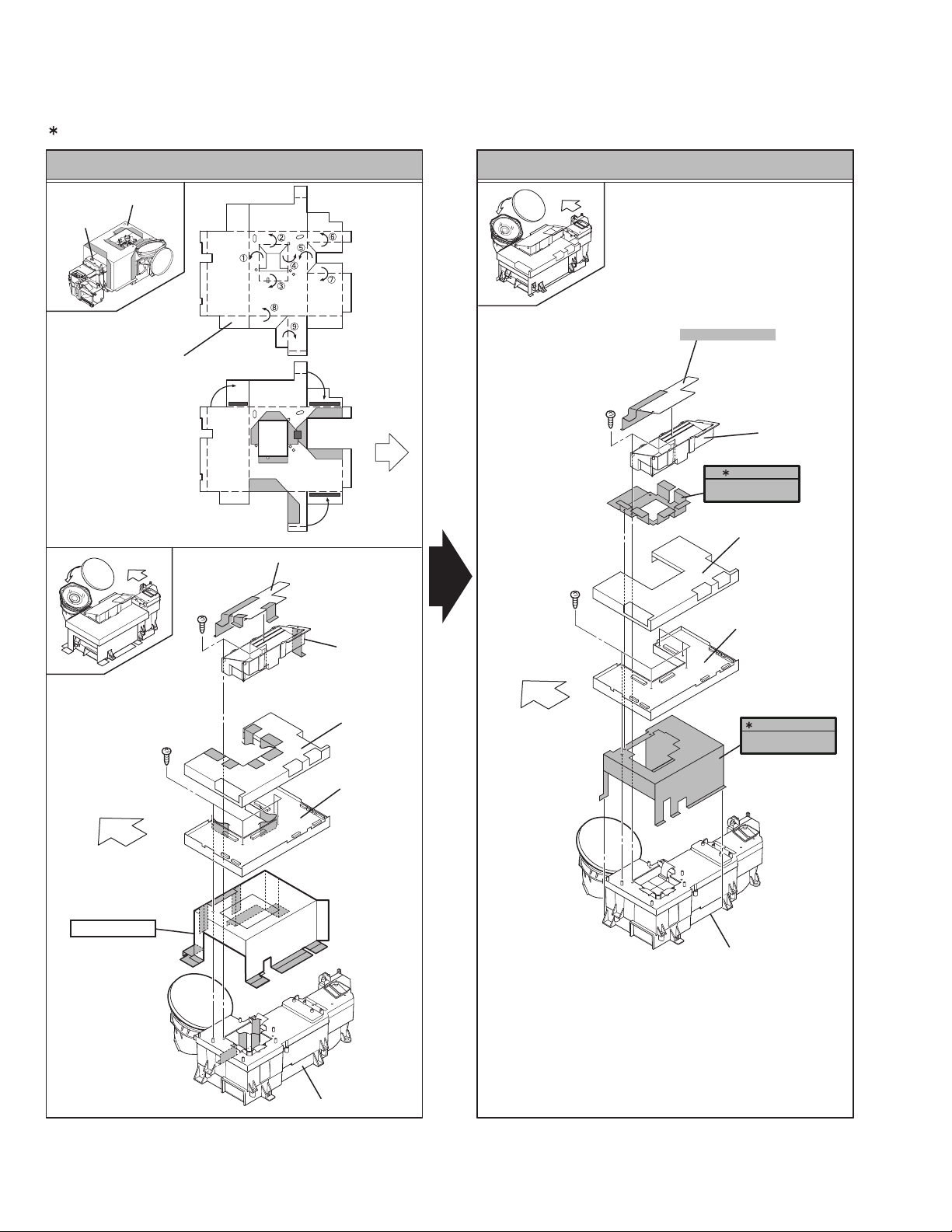
3.1.30 MAIN DRIVE PWB
• Take out the BODY COVER.
• Take out the BODY BRACKET.
• Take out the MAIN UNIT.
(1) Peel off the shield (copper film) tape 1 position [ M ].
(2) Take out the TOP DUCT PLATE.
(3) Remove 2 screws [ N ].
(4) Take out the TOP DUCT.
(5) Take out the DEVICE SHIELD.
(6) Take out the SHIELD TOP CASE.
(7) Remove 5 screws [ O ].
(8) Take out the MAIN DRIVE PWB.
3.1.31 OPTICAL BLOCK COOLING FAN
• Take out the BODY COVER.
• Take out the BODY BRACKET.
• Take out the MAIN UNIT.
(1) Remove 3 screws [ P ].
(2) Take out the SIROCCO TOP CASE.
(3) Remove 3 screws [ Q ].
(4) Take out the OPTICAL BLOCK COOLING FAN.
3.1.32 LAMP COOLING FAN
• Take out the BODY COVER.
• Take out the BODY BRACKET.
• Take out the MAIN UNIT.
(1) Remove 2 screws [ R ].
(2) Take out the LAMP FAN BRACKET ASSY.
(3) Remove 4 screws [ S ].
(4) Take out the LAMP COOLING FAN.
3.1.33 LAMP BALLAST UNIT COOLING FAN
• Take out the BODY COVER.
• Take out the BODY BRACKET.
• Take out the MAIN UNIT.
(1) Remove 3 screws [ T ].
(2) Remove 4 screws [ U ].
(3) Take out the COOLING FAN (LAMP BALLAST UNIT).
3.1.34 LAMP BALLAST UNIT
• Take out the BODY COVER.
• Take out the BODY BRACKET.
• Take out the MAIN UNIT.
• Take out the LAMP BALLAST UNIT COOLING FAN.
(1) Take out the wire of LAMP BALLAST UNIT.
(2) Remove 4 screws [ V ].
(3) Take out the BALLAST BRACKET BOTTOM.
(4) Remove 4 screws [ W ].
(5) Take out the BALLAST COVER.
(6) Take out the LAMP BALLAST UNIT.
3.1.35 LAMP COVER SW PWB
• Take out the BODY COVER.
• Take out the BODY BRACKET.
• Take out the MAIN UNIT.
(1) Remove 1 screw [ X ].
(2) Take out the LAMP COVER SW PWB.
3.1.36SHIELD PLATE ATTACHMENT PROCESS
1-19 page is deleted.
(No.YA092C)3
Page 4

FRONT
FRONT SHADE
BRACKET
F
(x2)
H
I
ADD. PART
G
(x1)
OPTICAL / DRIVE
ASS'Y
TEMP SENSOR
PWB
BODY
REMOTE SENSOR
PWB
E
(x1)
SHADE
COVER
P
(x3)
LAMP UNIT
LAMP
COOLING FAN
D
J
(x1)
(x1)
FAN CONTROL
PWB
L
(x2)
THERMOSTAT
K
(x4)
LAMP FAN
BRACKET ASSY
B
(x2)
ADD. PART
DEVICE
SHIELD
O
(x5)
FRONT
R
(x2)
C
N
(x2)
(x2)
M
(x1)
A
(x2)
LAMP FAN
DUCT
T
(x3)
BALLAST BRACKET
(LAMP BALLAST UNIT)
TOP DUCT PLATE
TOP DUCT
SHIELD TOP
CASE
MAIN DRIVE
PWB
CHANGED PART
SHIELD COVER
OPTICAL BLOCK
TOP
COOLING FAN
SIROCCO
TOP CASE
OPTICAL BLOCK
COOLING FAN
FRONT
4(No.YA092C)
S
(x4)
V
(x4)
X
(x1)
Q
(x3)
LAMP COVER
SW PWB
UNIT BASE
W
U
(x4)
(x4)
BALLAST BRACKET
BOTTOM
BALLAST
COVER
LAMP BALLAST
UNIT
Page 5

PARTS LIST
DIFFERENCE PARTS LIST
EXPLODED VIEW PARTS LIST-4 (Page3-9)
Ref.No.
Previous New
Part No.
Part Name Description
92 QQR0490-001 QQR0490-001 NOISE FILTER
E
XPLODED VIEW-4 (Page3-10)
BODY
205
PWB HOLDER
FRONT
207
206
QTY(x3)→(x2)
92
91
89
87
208
89
89
94
87
86
88
92
DELETE
90
93
203
93
85
204
POWER PWB
BRACKET
UNIT BASE
93
84
ANALOG
BRACKET
83
82
209
81
80
82
79
(No.YA092C)5
Page 6

EXPLODED VIEW PARTS LIST-5 (Page3-11)
Ref.No.
124 LC41546-014A
Previous
Part No.
New
---------------------- --------------------- Delete (GASKET)
Part Name Description
125 LC42031-005A-A
127 LC42023-001A-A
128 LC32891-001A-A
129 LC42031-004A-A
130 LC42010-001A
131 LC42031-007A-A
133 ----------------------
134 ----------------------
EXPLODED VIEW-5 (Page3-11)
---------------------- --------------------- Delete (SHIELD TAPE)
---------------------- --------------------- Delete (SHIELD PLATE)
---------------------- --------------------- Delete (SHIELD PLATE(A))
---------------------- --------------------- Delete (SHIELD TAPE)
LC42081-001A SHIELD TAPE FPC SHIELD
---------------------- --------------------- Delete (SHIELD TAPE)
LC41843-001A-C CLIP SPRING Addition
QQR0492-001 CORE FILTER Addition
TOP DUCT PLATE
126
BOTTOM SIDE
123
DEVICE SHIELD
FRONT
132
SHIELD TOP CASE
OPTICAL BLOCK
212
130
(Changed)
6(No.YA092C)
Page 7

(Page3-12)
BODY
FRONT
98
99
FRONT SHADE
BRACKET
133
ADD. PART
120
213
100
97
121
122
210
101
96
109
122
95
COOLING FAN
BRACKET
102
103
211
104
105
134
ADD. PART
106
BALLAST BRACKET
TOP
109
108
116
117
118
114
115
119
107
214
UNIT BASE
BALLAST
BRACKET
BOTTOM
122
110
111
112
113
(No.YA092C)7
Page 8

Victor Company of Japan, Limited
AV & MULTIMEDIA COMPANY VIDEO DISPLAY CATEGORY 12, 3-chome, Moriya-cho, kanagawa-ku, Yokohama, kanagawa-prefecture, 221-8528, Japan
(No.YA092C)
Printed in Japan
 Loading...