

Page 1
HA-W400RF (EG)/(EK)
SERVICE MANUAL
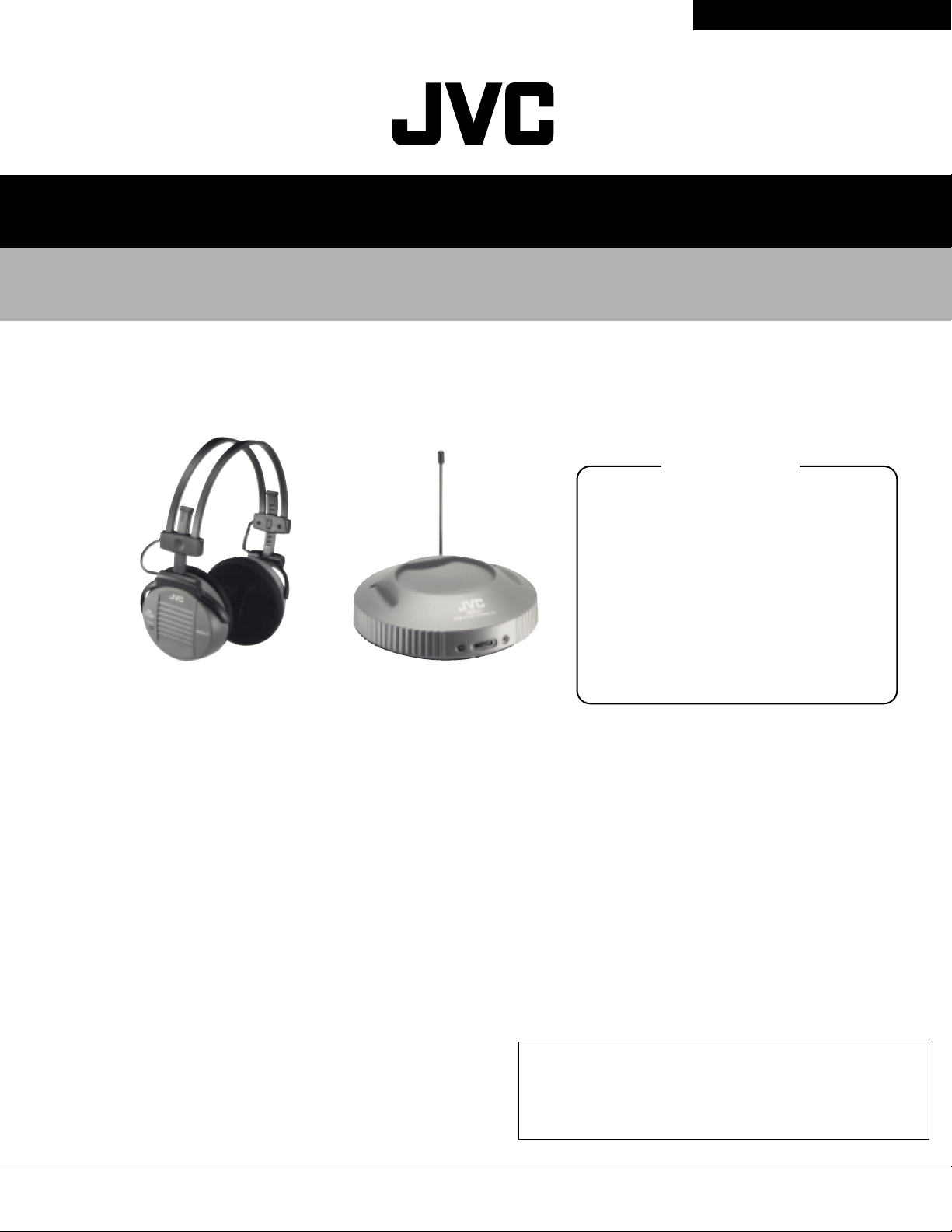
CORDLESS FM STEREO HEADPHONES
HA-W400RF (EG)/(EK)
Specifications
General Specifications
System : Radio Frequency (UHF stereo)
Modulation : Frequency modulation
Carrier frequency : 863-865 MHz
Usable area
(distance to reach) : Approx. 100m (328 ft) : using
JVC measurements systems
Frequency response : 28 Hz-14 000 Hz
Distortion : Less than 4 % (at 1 kHz)
Transmitter (J21967-002)
Power requirements : DC 12 V (with the exclusive AC
adaptor J46857-001(EG Model)
/J46858-001(EK Model))
Audio input terminal : 3.5 mm dia. stereo mini plug
Input impedance : 35 kΩ
Reference input level : 300 mV
Dimensions : 137(W) x 147(D) x 123(H) mm
(5-7/16" x 5-13/16" x 4-7/8")
(Including antenna)
Mass : 200 g (7.1 oz)
(Without connection cord and AC
adaptor)
* Design and specifications subject to change without notice.
Contents
Specifications..................................... Front cover
1. Operating Manual........................................ 3
2. Disassembly................................................ 12
3. Schematic Diagram..................................... 13
4. Print Circuit Board...................................... 14
5. Measurement Condition.............................. 14
6. Wiring Diagram........................................... 16
7. Block View Inside IC................................... 16
8. Block Diagram............................................. 17
9. Electric Parts List........................................ 17
10. Exploded view............................................. 18
11. Mechanical Parts List................................. 18
12. Packing Method.......................................... 19
13. Packing Materials....................................... 19
14. Accessories List......................................... 19
Headphones (HA-W400RF)
Power requirements : Rechargeable
Ni-Cd battery (1.2 V) x 2
Battery running time : 6 hours
(When charged for 24 hours)
Mass : 220 g (7.7 oz)
(With provided rechargeable
Ni-Cd battery x 2)
Provided Accessories
Instructions x 1
AC adaptor x 1
Connection cord x 1 (3.5 mm dia. stereo mini jack-
RCA pin plug x 2 : 0.1 m (0.3 ft))
Plug adaptor x 1 (converts 3.5 mm dia. stereo
mini plug to a 6.3 mm dia. standard
stereo phone plug)
Exclusive rechargeable Ni-Cd battery x 2
This product has Auto-tuning function.
On noisy frequency part, the receiver in headphone starts searching the
transmitted frequency and stop tuning on the frequency.
In the condition of disturbing frequencies and / or in the place at a distance
from transmitter, auto-tuning function could start searching by potential
noise and it causes sound breaks.
COPYRIGHT C 2000 VICTOR COMPANY OF JAPAN,LTD.
No.70245
Jul.2000
Page 2
HA-W400RF (EG) /(EK)
Safety Precautions
1. This design of this product contains special hardware and many circuits and components specially
for safety purposes. For continued protection, no changes should be made to the original design
unless authorized in writing by the manufacturer. Replacement parts must be identical to those
used in the original circuits. Services should be performed by qualified personnel only.
2. Alterations of the design or circuitry of the product should not be made. Any design alter ations of
the product should not be made. Any design alterations or additions will void the manufacturer`s
warranty and will further relieve the manufacture of responsibility for personal injury or property
damage resulting therefrom.
3. Many electrical and mechanical parts in the products have special safety-related characteristics.
These characteristics are often not evident from visual inspection nor can the protection afforded
by them necessarily be obtained by using replacement components rated for higher voltage,
wattage, etc. Replacement parts which have these special safety characteristics are identified in
the Parts List of Service Manual. Electrical components having such features are identified by
shading on the schematics and by ( ) on the Parts List in the Service Manual. The use of a
substitute replacement which does not have the same safety characteristics as the recommended
replacement parts shown in the Parts List of Service Manual may create shock, fire, or other
hazards.
4. The leads in the products are routed and dressed with ties, clamps, tubings, barriers and the
like to be separated from live parts, high temperature parts, moving parts and/or sharp edges
for the prevention of electric shock and fire hazard. When service is required, the original lead
routing and dress should be observed, and it should be confirmed that they have been returned
to normal, after re-assembling.
5. Leakage currnet check (Electrical shock hazard testing)
After re-assembling the product, always perfor m an isolation check on the exposed metal parts
of the product (antenna terminals, knobs, metal cabinet, screw heads, headphone jack, control
shafts, etc.) to be sure the product is safe to operate without danger of electrical shock.
Do not use a line isolation transformer during this check.
Plug the AC line cord directly into the AC outlet. Using a "Leakage Current Tester", measure
the leakage current from each exposed metal parts of the cabinet , particularly any exposed
metal part having a return path to the chassis, to a known good earth ground. Any leakage
current must not exceed 0.5mA AC (r.m.s.)
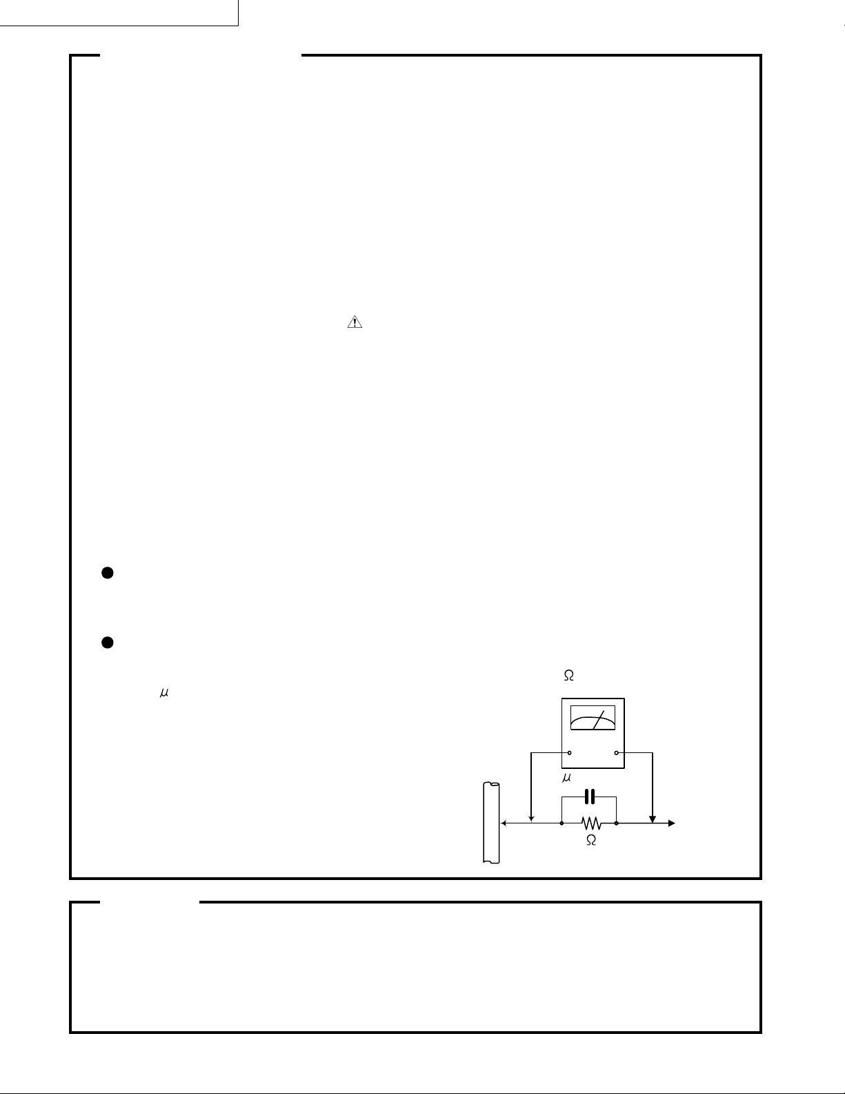
Alternate check method
Plug the AC line cord directly into the AC outlet. Use an AC voltmeter having, 1,000 ohms
per volt or more sensitivity in the following manner. Connect a 1,500 10W resistor paralleled by
a 0.15 F AC-type capacitor between an exposed
metal part and a known good earth ground.
Measure the AC voltage across the resistor with the
AC voltmeter.
Move the resistor connection to eachexposed metal
part, par ticularly any exposed metal part having a
return path to the chassis, and meausre the AC
voltage across the resistor. Now, reverse the plug in
the AC outlet and repeat each measurement. voltage
measured Any must not exceed 0.75 V AC (r.m.s.).
This corresponds to 0.5 mA AC (r.m.s.).
0.15 F AC TYPE
1500 10W
Good earth ground
AC VOLTMETER
(Having 1000
ohms/volts,
or more sensitivity)
Place this
probe on
each exposed
metal part.
Warning
1. This equipment has been designed and manufactured to meet international safety standards.
2. It is the legal responsibility of the repairer to ensure that these safety standards are maintained.
3. Repairs must be made in accordance with the relevant safety standards.
4. It is essential that safety critical components are replaced by approved parts.
5. If mains voltage selector is provided, check setting for local voltage.
2 (No.70245)
Page 3

1.Operating Manual
HA-W400RF (EK)
© 2000 VICTOR COMPANY OF JAPAN, LIMITED
Printed in China
J5500-101A
VICTOR COMPANY OF JAPAN, LIMITED
CORDLESS FM STEREO HEADPHONES
J5500-101A
INSTRUCTIONS
HA-W400RF (EK)
CORDLESS FM STEREO HEADPHONES
HA-W400RF (EG)/(EK)
(No.70245) 3
Page 4
HA-W400RF (EG) /(EK)
2
“SOME DO’S AND DON’TS ON THE SAFE USE OF EQUIPMENT”
This equipment has been designed and manufactured to meet international safety
standards but, like any electrical apparatus, care must be taken if you are to obtain
the best results and safety is to be assured.
○○○○○○○○○○○○○○○○○○○○○○○○○○○○○○○○○○○○○○○○
Do read the operating instructions before you attempt to use the equipment.
Do ensure that all electrical connections (including the plug, extension cord and
inter-connections between pieces of equipment) are properly made and in
accordance with the manufacturer’s instructions. Switch off and withdraw the
plug when making or changing connections.
Do consult your dealer if you are ever in doubt about the installation or operation or
safety of your equipment.
Do be careful with glass panels or doors on equipment.
○○○○○○○○○○○○○○○○○○○○○○○○○○○○○○○○○○○○○○○○
DON’T continue to operate the equipment if you are in any doubt about it working
normally, or if it is damaged in any way—switch off—withdraw the plug and
consult your dealer.
DON’T remove any fixed cover as this may expose dangerous voltages.
DON’T leave equipment switched on when it is unattended unless it is specifically
stated that it is designed for unattended operation or has a standby mode.
Switch off using the switch on the equipment and make sure that your family
know how to do this.
Special arrangements may need to be made for infirm or handicapped
people.
DON’T use equipment such as personal stereos or radios so that you are distracted
from the requirements of road safety. It is illegal to watch television when
driving.
DON’T listen to headphones at high volume as such use can permanently damage
your hearing.
DON’T obstruct the ventilation of the equipment, for example with curtains or on
soft furnishings.
Overheating will cause damage and shorten the life of the equipment.
DON’T use makeshift stands and NEVER fix legs with wood screws. To ensure
complete safety always fit the manufacturer’s approved stand or legs with
the fixing screws supplied according to the instructions.
DON’T allow electrical equipment to be exposed to rain or moisture.
ABOVE ALL
NEVER let anyone especially children push anything into holes, slots or any
other opening in the case. This could result in a fatal electrical shock.
NEVER guess or make changes with electrical equipment of any kind. It is
better to be safe than sorry!
3
DECLARATION OF CONFORMITY
WE
Victor Company of Japan, Ltd.
12,3-chome
Moriya-cho, kanagawa-ku
YOKOHAMA (kanagawa) 221-8528, Japan
declare on our sole responsibility, that the product
HA-W400RF (JVC Brand) Stereo Wireless Headphone System
to which this declaration relates is in conformity with the following standard(s) or other
normative document(s):
EN 301 357 V1.1.1 (July 1999)
EN 300 220-1 (November 1997)
TCF reference:RFI/TCFB1/RP40782(Notified Body No. used:889)
ETS 300 683 (1997)
EN 60950 (1992) with amendments A1 (1993), A2 (1993), A3 (1995), A4
(1997) and A11 (1997)
following the provisions of the Radio Equipment and T elecomm unications Terminal
Equipment Directive 1999/5/EC, using the conformity assessment procedures from
the EMC Directive 89/336/EEC and the LVD 73/23/EC for EMC (Article 3.1b) and
Safety (Article 3.1a) respectively.
Place and date of issue Manufacturer/Authorized representative
name and signature
CORDLESS FM STEREO HEADPHONES
OPERATING AT 863 MHz TO 865 MHz
ACCORDING TO THE USED FREQUENCY BAND THIS DEVICE IS INTENDED TO
USE IN GERMANY, THE UK, FRANCE, AUSTRIA, THE NEDERLANDS, SWEDEN,
NORWAY, DENMARK, FINLAND
4 (No.70245)
Page 5
HA-W400RF (EG)/(EK)
4
CAUTION
To reduce the risk of electrical shocks, fire, etc.:
1. Do not remove screws, cover or cabinet.
2. Do not expose this appliance to rain or moisture.
IMPORTANT
1. Installation
● Select a place which is level, dry
and neither too hot nor too cold
(between 0°C and 35°C /32°F and
95°F).
● Keep away from direct sunlight.
● Do not put it too close to a heater.
2. Power cord
● Do not handle the power cord with
wet hands!
● Do not bend the power cord
sharply.
3. Malfunctions, etc.
● There are no serviceable parts
inside. If anything goes wrong,
unplug the power cord and consult
your dealer.
● Do not insert any metallic object.
● Do not allow water to get inside.
CAUTION:
CHARGE ONLY WITH PROVIDED NICKEL-CADMIUM TYPE
BATTERIES. OTHER TYPES OF BATTERIES MAY BURST
CAUSING PERSONAL INJURY AND DAMAGE.
Thank you for purchasing this JVC product.
Before you begin operating this unit, please read the instructions carefully to be
sure you get the best possible performance.
If you have any questions, consult your JVC dealer.
FEATURES
● Frequency modulation system which
allows headphones to be used even in
areas where the transmitter cannot be
seen
● Reception range (up to 100 m (328 ft):
using JVC measurement system)
● Auto Tuning Function: Lock in the
signal at the touch of a button
● Foldable and compact design
● Easy-to-handle light body
● Rechargeable system with Ni-Cd
batteries provided
● Large 40 mm dia. drivers for high-
quality sound
● Automatic Power On/Off transmitter
● Auto-level control circuit that automati-
cally adjusts signals to the appropriate
modulation level
● Single volume control adjusts the
volume level of the left and right
channels simultaneously
● Adaptable to any audio/visual equip-
ment
5
NAMES OF PARTS AND THEIR FUNCTIONS
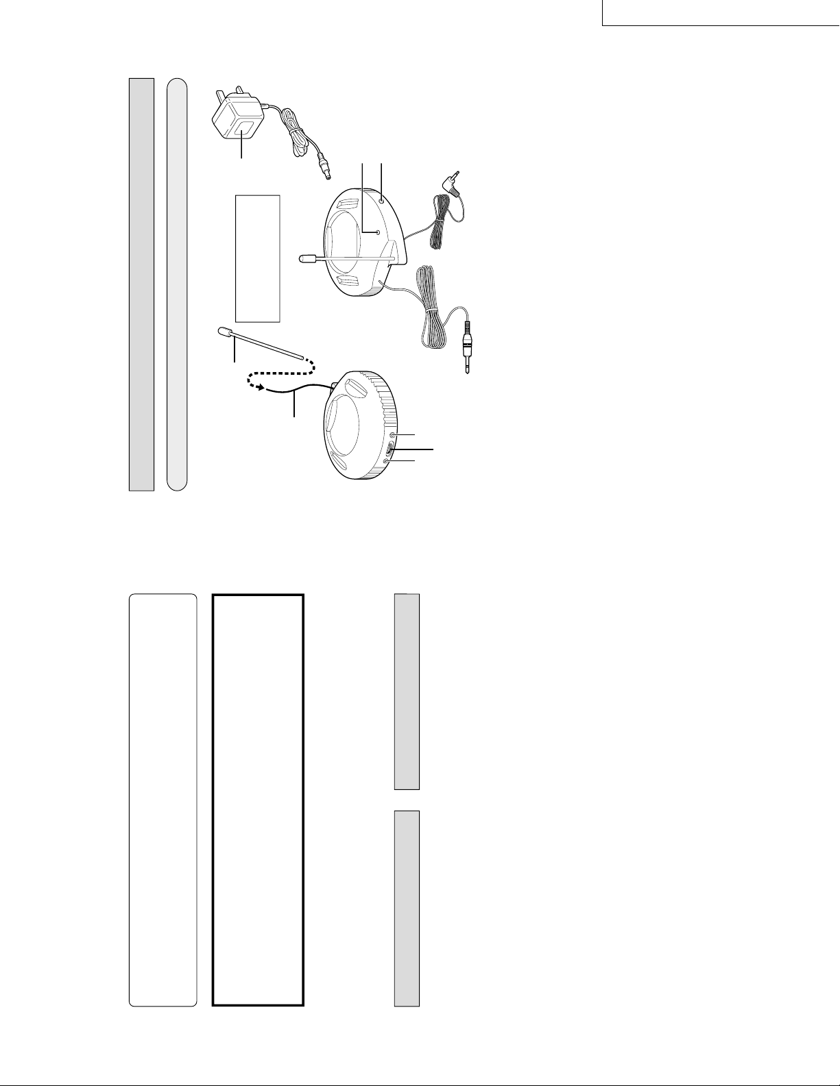
Transmitter
1
POWER (Indicator)
When an audio signal is input : The
power automatically turns on and the
indicator lights in green.
2
CHARGE (Indicator)
The indicator lights in red while the
battery is being charged.
3
TUNING (Tuning control)
Adjusts the transmission frequency.
4
ANTENNA
5
ANTENNA COVER
Cover the antenna
4
before using
the unit.
6
Audio input cord and plug
2m cord and 3.5mm dia. stereo
miniplug.
7
Charging output cord and plug
8
DC IN (DC 12 V jack)
9
AC adaptor (J46858-001)
Connects to a household AC outlet
(AC 230 V, 50 Hz).
Note :
The provided AC adaptor is exclusively
for use with this unit.
Do not connect to any other equipment.
0
Plug rest hole
While not in use, charging output
cord and plug
7
can be inserted
into this hole.
7
6
8
0
3
12
4
5
9
Insert the antenna
4
into
the antenna cover
5
before using the unit.
(No.70245) 5
Page 6

HA-W400RF (EG) /(EK)
6
NAMES OF PARTS AND THEIR FUNCTIONS
Receiver (Cordless Headphones)
1
ON/OFF (Power switch)
2
Charging input terminal
3
VOL. (Volume control)
Adjusts the volume level of the left
and right channels simultaneously.
4
POWER (Indicator)
The indicator lights in red when the
power is turned on.
5
AUTO TUNING SWITCH (Tuning
control)
Adjusts the reception frequency.
When the button is pressed,
frequency tuning starts automatically
and it stops when a signal is
detected.
Note :
Signals not originating from the trans-
mitter or unexpected signals can also
cause the frequency tuning to stop. If
this happens, press the button again to
resume tuning.
6
STEREO (Indicator)
The indicator lights in green when
receiving the signal from the
transmitter.
Note :
The indicator also lights in green with
signals not originating from the
transmitter.
1
2
3
6
5
4
7
䡵
How to connect to AV equipment
Connection to HEADPHONES jack
CONNECTION
Connection to LINE OUT or REC OUT terminals
TV, audio amplifier,
VCR, tape deck,
video disc player,
etc.
To LINE OUT or REC
OUT terminals
L-channel
(white plug)
R-channel
(red plug)
Provided
connection cord
When connecting to a standard stereo phone jack
(6.3 mm dia.)
— Use the provided plug adaptor
(Converts a stereo miniplug to a standard stereo
phone plug)
When
connecting to a
stereo minijack
When connecting to a monaural minijack
— Use an optional plug adaptor
(Converts a stereo miniplug to a monaural miniplug)
TV, audio amplifier,
VCR, tape deck,
video disc player,
etc.
To HEADPHONES jack
6 (No.70245)
Page 7

HA-W400RF (EG)/(EK)
8
Connection to power supply
CONNECTION
Plug polarities
To AC outlet
(AC 230 V, 50 Hz)
Note:
Be sure to use the provided exclusive AC adaptor (J46858-001) for connection. Use of any
other AC adaptor may cause a malfunction.
In places such as inside an apartment
with reinforced concrete walls, or when
the transmitter and headphones are
separated by obstacles such as
steel-reinforced doors.
When items such as
metal furniture are
situated nearby.
● Be sure to keep this unit
more than 0.5 m/1.64 ft
away from concrete
walls, metal furniture,
etc.
Note:
The usable area may differ depending on building structure, etc.
The range becomes shorter in the following cases:
The usable area between the transmitter and
the headphones is within a radius of approx.
100 m/328 ft (based on measurements taken
when placed in direct view in a straight line).
RANGE OF USE
To DC IN 12 V jack
Provided exclusive
AC adaptor
(J46858-001)
100 m/328 ft
9
POWER REQUIREMENTS OF HEADPHONES
Use two exclusive rechargeable Ni-Cd batteries to power the headphones.
When you purchase this unit, be sure to charge the provided rechargeable Ni-Cd
batteries according to the following procedures before use.
Cautions about the rechargeable batteries
If the batteries are used incorrectly, they may leak, heat or explode, and may cause
fire, injury or soiling. Make note of the following:
1. Be sure to use the provided exclusive Ni-Cd batteries. Do not use any other rechargeable
Ni-Cd battery or dry cell battery.
2. Insert batteries with the (+) and (
–) polarities correctly positioned, following the indications
on the equipment.
3. Do not use a new battery with an old one, and do not use batteries holding different
amounts of charge together.
4. Do not throw batteries in a fire or heat them.
5. Do not short-circuit the positive (+) and negative (
–) terminals. Also, do not carry or store
them with small metallic objects such as necklaces or coins.
6. Do not deform, take apart, modify or directly solder the batteries.
7. Do not remove or damage the covering tube.
8. If you notice phenomena that has never happened before, such as leakage, colour change
or deformity, stop using the batteries.
9. If any liquid from the batteries gets into your eyes, it may cause blindness. If battery liquid
does get into your eyes, do not rub them, but instead immediately wash them thoroughly
with clean water, then consult a doctor at once. Also, should any liquid from the recharge-
able batteries get onto your skin or clothes, it may burn your skin. In this case, wash with
clean water immediately.
10. Do not immerse or wet the batteries in water.
11. Do not use or leave the batteries in an area where the temperature becomes significantly
higher, such as in direct sunlight, inside a car on a hot day or near heat-generating equip-
ment.
12. Do not subject the batteries to strong shocks or throw them.
13. Be sure to read the cautions on the batteries.
Please consult your JVC dealer when exchanging the batteries.
1.
Insert the rechargeable Ni-Cd batteries
1
Remove the battery compartment
cover on the right side of headphones.
2
Insert the two rechargeable Ni-Cd
batteries with the polarities correctly
positioned.
(No.70245) 7
Page 8
HA-W400RF (EG) /(EK)
10
3
1
2
4
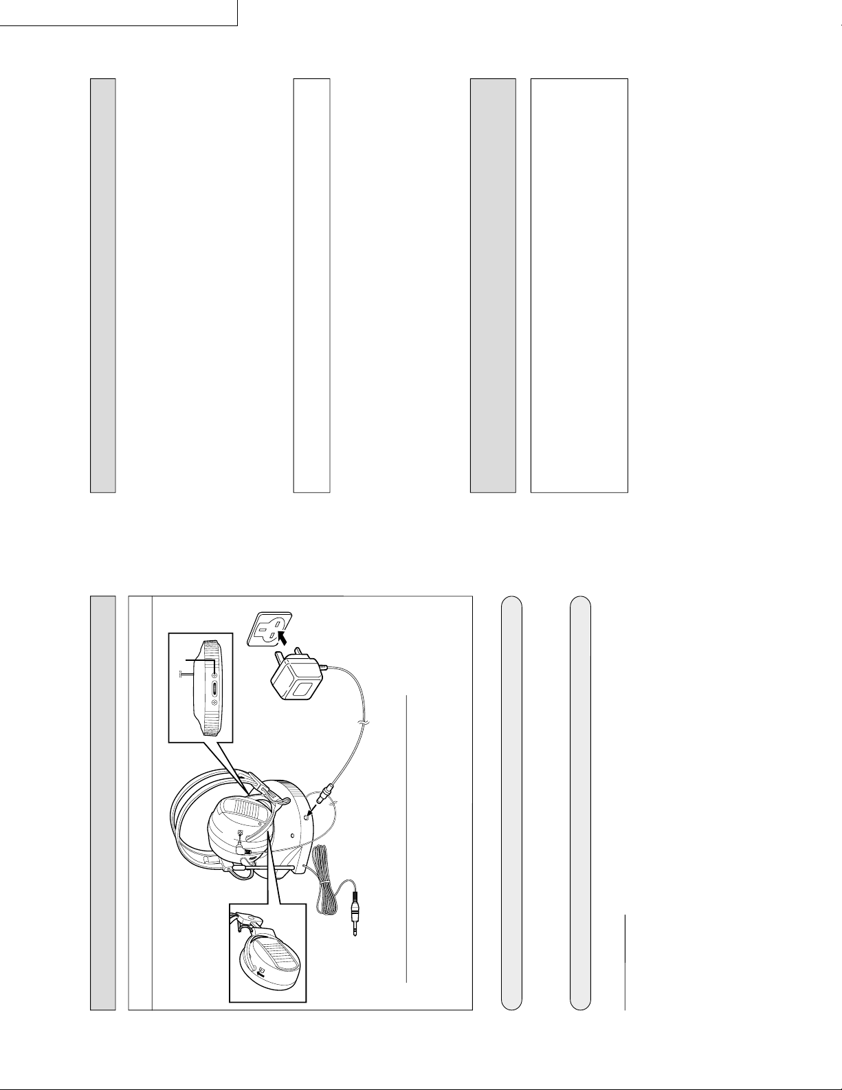
POWER REQUIREMENTS OF HEADPHONES
2.
Charging rechargeable Ni-Cd batteries
Battery running time
After charging is complete, you can use them continuously for approx. 6 hours.
Tips for better use
● Be sure to charge the batteries within the temperature range of 10
° C ~ 35° C
(50 °F ~ 95 °F ).
● Charging batteries that are not completely exhausted will cause efficiency to
decline. Be sure to charge them after they have been completely exhausted.
1
Set the ON/OFF (power) switch on the headphones to OFF.
The batteries cannot be charged when the switch is set to ON.
2
Connect the charging output cord from the transmitter to the headphones.
3
Connect the AC adaptor to the transmitter.
4
Plug the AC adaptor into an AC outlet. The charger starts charging the batteries
automatically and the transmitter
’s indicator lights in red.
Charging time
The battery can be fully charged in approx. 24 hours.
To AC outlet
11
CAUTIONS ABOUT THE
RECHARGEABLE BATTERY
ATTENTION:
The product that you have purchased contains a rechargeable battery. The
battery is recyclable. At the end of its useful life, under various state and local
laws, it may be illegal to dispose of this battery into the municipal waste stream.
Check with your local solid waste officials for details in your area for recycling
options or proper disposal.
CAUTIONS ABOUT CHARGING
1. Be sure to use only this unit for charging.
2. You can charge the rechargeable Ni-Cd batteries approx. 300 times.
3. Charging times differ depending on the temperature range or the amount of charge
already in the batteries.
4. Excessive charging doesn't result in malfunction.
5. Battery life will decrease in cold places.
6. If the usable time of fully-charged batteries decreases by about half, replace them
with new ones. When purchasing rechargeable Ni-Cd batteries, consult the dealer
from whom you bought this product.
Exclusive Rechargeable Ni-Cd Batteries :
J46863-001 (1.2 V, 240 mAh, 2 pcs/pack)
7. Though the rechargeable batteries may become hot after they have been charged
or used, this is not malfunction.
8. Due to characteristics of the batteries, they expend their charge a little even when
the power is turned off.
8 (No.70245)
Page 9

HA-W400RF (EG)/(EK)
12
HOW TO USE
1. Connect the transmitter and AV equipment. (Refer to page 6)
2. Connect the AC adaptor to the transmitter, then plug the AC adaptor into an
AC outlet. (Refer to page 7)
3. Turn on the power on the transmitter and the connected AV equipment.
4. Turn on the headphones
’ power. To avoid excessive volume, first set the
headphones’ volume to a low level.
Transmitter power
When an audio signal is input, the transmitter
’s power is turned on automatically, and the
indicator lights in green. Also, when no audio signal is input for about a minute, the
indicator goes out automatically and the power turns off. (Automatic Power On/Off function)
In some situations, the power may not be turned on automatically by the input sound
(e.g. a song with a quiet opening or gradual fade-in). This is not a malfunction.
Before using the headphones for the first time, charge the rechargeable Ni-Cd battery.
13
Tips for better use
For improved sound quality, set the volume level of the connected equipment as high as
possible without causing distortion, while setting the volume level of the headphones to a
slightly lower level.
Within approx.
7 m/23 ft
To set optimum signal reception, adjustments
should be done within a range of approx. 7 m/23 ft
between the transmitter and the headphones.
5. Adjust the volume control of the connected AV equipment and the head-
phones, and set them to the desired listening level.
6. Push the AUTO TUNING switch control to get the best reception in the
headphones.
When the button is pressed, frequency tuning starts automatically and it stops
when a signal is detected.
Note :
Signals not originating from the transmitter or unexpected signals can also cause
the frequency tuning to stop. If this happens, press the button again to resume
tuning.
In cases of interference or too much noise, turn the TUNING control on the
transmitter to another position, then repeat step 6.
HOW TO USE
After use
Keep the headphones
’ power off.
Notes:
1. When using the headphones, don
’t raise the volume excessively. Continuous
listening for a long time at high volumes may damage your hearing.
2. For safety reasons, do not use the headphones while riding a bicycle or driving a
motorcycle, car, etc.
(No.70245) 9
Page 10

HA-W400RF (EG) /(EK)
14
TROUBLESHOOTING
What appears to be a malfunction may not always be serious. First make
sure...
Remedy
Check the connection of the
transmitter.
Turn the power on the connected
AV equipment ON and start
playing.
Turn on the headphones
’ power.
(The indicator lights.)
Fully charge the headphones.
Adjust the volume of the head-
phones to the appropriate level.
Raise the volume level of the
connected AV equipment as high
as possible without causing
distortion.
Connect them with an optional plug
adaptor. (Converts monaural audio
output to stereo audio output.)
Fully charge the headphones.
Adjust the volume level of the
connected AV equipment as high
as possible without causing
distortion.
Fully charge the headphones.
Push the AUTO TUNING switch on
the headphones or turn the
TUNING controls on the transmit-
ter to adjust them until the
headphones’ indicator lights in
green.
Adjust the volume level of the
connected AV equipment as high
as possible without causing
distortion.
Use them within the range the
frequency modulation signal can
reach. (Refer to page 8.)
Replace it with a new Ni-Cd
battery. Please consult your dealer
for replacement.
Cause
Is the transmitter
’s power OFF?
Is the headphones
’ power OFF?
Is the battery in the headphones
exhausted?
Is the volume of the headphones
set to the minimum level?
Is the volume of the connected AV
equipment set to the minimum
level?
Is the transmitter connected to
equipment with monaural audio
output?
Is the battery in the headphones
exhausted?
Is the volume of the connected AV
equipment set too high?
Is the battery in the headphones
exhausted?
Are the frequency modulation
signals being received correctly?
Is the volume of the connected AV
equipment set too low?
Are the headphones too far away
from the transmitter?
Has the rechargeable Ni-Cd
battery expired?
Symptoms
No sound.
No sound from
the R-channel.
Distorted sound.
Noisy sound.
Battery charging
is impossible.
15
SPECIFICATIONS
General Specifications
Modulation system : Stereo frequency modulation system
Carrier frequency : 863 – 865 MHz
Usable area
(distance to reach) : Approx. 100 m (328 ft)
(using JVC measurement systems)
Frequency response : 28 –14,000 Hz
Distortion : Less than 4% (at 1 kHz)
Transmitter (J21967-002)
Power requirements : DC 12 V (with the exclusive AC adaptor J46858
–001)
Audio input terminal : 3.5 mm dia. stereo miniplug
Input impedance : 35 kΩ
Reference input level : 300 mV
Dimensions : 137(W) x 147(D) x 123(H) mm
(5-7/16" x 5- 1 3/ 1 6 " x 4- 7/8" ) (including antenna)
Weight : 200 ˝ (7.1 oz) (Without connection cord and AC adaptor)
Headphones (HA-W400RF)
Power requirements : Rechargeable Ni-Cd battery (1.2 V) x 2
Battery running time : 6 hours (When charged for 24 hours)
Weight : 220 ˝ (7.7 oz)
(With provided rechargeable Ni-Cd battery x 2)
Provided Accessories
Instructions x 1
AC adaptor x 1
Connection cord x 1 (3.5 mm dia. stereo minijack
— RCA pin plug x 2 : 0.1 m (0.3 ft))
Plug adaptor x 1 (converts 3.5 mm dia. stereo miniplug to a 6.3 mm dia. standard
stereo phone plug)
Exclusive
rechargeable
Ni-Cd battery x 2
* Design and specifications subject to change without notice.
10 (No.70245)
Page 11

-MEMO-
HA-W400RF (EG)/(EK)
(No.70245) 11
Page 12

HA-W400RF (EG) /(EK)
2.Disassembly
T ransmitter
In case of some problems arise in this transmitter unit,
have to change the transmitter unit itself, due to avoid
the law of radio regulation.
Receiver(Headphones)
-
0
~
3
2
=
1
2
5
5
1
9
4
6
7
8
1.Remove the ear pad 1 and the cushion 2 from the driver unit ass’y (L) 3 and (R) 4.
2.Remove the screw 5 and pull up the driver unit ass’y(L) 3 and (R) 4.
3.At channel R. remove the screw 6 and pull up the charge print circut board 7.
4.Remove the battery door 9 from the housing ass’y (R) 8.
5.At channel L. Remove the main print circut board 0 from the housing (L) -.
6.Remove the tuning switch knob =.
7.Remove the wire with solder from the charge and main print circut board 70, then remove the headband
ass’y ~.
12 (No.70245)
Page 13

3.Schematic Diagram
HA-W400RF (EG)/(EK)
ANT
TP1
C43
C23
4700p
(M)
R9
56k
u
0.0047
(M)
u
R36
15k
Q1
S9015C
R39
3.3k
D6
4148
C16
330p
( )
816
12
15
R21
30k
TP3
C39
0.001
4
C14
470p
u
C15
0.47
R6
330
R22
15k
R24
30k
TP4
C18
0.1
u
16 15
u
R20
390
HVU200A
C12
35p
C9
10p
R1
22k
22 20
C2
100p
D2
C10
4.7
u
R2
4.7k
L2
C11
43p
C7
25p
19
21
3
4.7
u
18 17
IC1
TA2111F
56
C4C3
++
4.7
u
C8
10p
D1
HVU200A
C7
25p
L1
23
1
C37
L5
56p
2.2
uH
C38
20p
TP2
ANT
IF
UHF
MODULE
RS872
VC+
C1
3p
R23
15k
R25
30k
C19
0.1
8
CF1
10.7MHz
IC3
74HC4060
R30
30k
R26
15k
u
R29
R27
330k
180k
10
11
9
7
4
61413
R33
30k
R31
15k
C21
6800p
(M)
R5
3.3k
C20
u
1
(MO)
11
R8
560
D3
LED
5
R40
30k
R34
30k
C22
6800p
(M)
9
R-O/P
13
12
CD1
10.7MHz
R35
15k
R10
56k
C6
220
R32
15k
L-O/P
14
2
R38
47k
C24
4700p
(M)
C25
4 7
C26
u
4 7
L3
2.2 H
SH2
SCAN
R28
390
+
VR2-1
50k
VR2-2
50k
u
R42
1k
+
R41
470k
u
L4
2.2 H
Q2
1623
u
TP6
TP5
C31
220
8
1
u
+
C33
0.1
R15
10
R11
2.2k
C28
47
C30
4.7
4.7
C34
220
C29
u
u
+
u
+
u
u
R12
6.8k
7
IC2
TDA2822S
2
+
C41
0.1
u
R13
6.8k
R14
2.2k
56
4
3
+
C32
220
u
TP7
C36
u
0.1
R16
10
TP8
!
SW1
R7
ON/OFF
560
D4
LED
JX1
CHARGE OUTPUT TERMINAL
!
!
BATTERY
2.4V
SPK2 (R)
32 Ω
SPK1 (L)
32 Ω
Use of Circuit Diagram
Notes:
1. The thick line ( ) is the B (+) power supply.
2. This circuit diagram is the reference diagram. Circuits and constans are subject to change without notice for
improvement.
3. Values printed in red show the voltares of each section measured by the tester (internal resistance 20 kOhms/V),
with the power switch ON.
4. Parts marked with !(in the shaded area ) are safety parts.When replacing these, be sure to use only the
designated parts to ensure safety.
(No.70245) 13
Page 14

HA-W400RF (EG) /(EK)
4.Measurement Condition
AC IN
Transmitter
5.Print Circuit Board
Receiver (Headphones)
CHARGE P. C. BOARD
TOP
Reference input signal :1kHz 300mVp-p sine wave
Hedaphone volume control : MAX
Distance : 1m (3.28ft)
Receiver (Headphones)
shows the B(+) power supply
shows the ground
shows others.
14 (No.70245)
Surface Back side
Page 15

5.Print Circuit Board
Receiver (Headphones)
MAIN P. C. BOARD
TOP
HA-W400RF (EG)/(EK)
shows the B(+) power supply
shows the ground
shows others.
E
D
C
B
Surface
Receiver (Headphones)
MAIN P. C. BOARD Location
Synbol No Location
Module
RS862u 4C
ICs
IC1 3D
IC2 1C
IC3 3A
Trunsistors
Q1 4B
Q2 2D
Filters
CD1 2D
Piezoelectric
cer. vibrators
CF1 3D
Diodes
D1 3B
D2 3B
D3 4B
D6 4B
Resistors
VR2 1B
R1 3B
R2 2B
R5 2C
R6 4E
R8 4B
R9 2C
Synbol No Location
Resistors
R10 2C
R11 1C
R12 1C
R13 2C
R14 2C
R15 1D
R16 1D
R20 3A
R21 3A
R22 2B
R23 2B
R24 2B
R25 2B
R26 2A
R27 3A
R28 3B
R29 3A
R30 2A
R31 2B
R32 2B
R33 2B
R34 2A
R35 1B
R36 2A
R38 3B
R39 4A
A
1234
Synbol No Location
Resistors
R40 2A
R41 2D
R42 1D
J1 3A
J2 2D
J3 3B
J5 2D
Capacitors
C1 4B
C2 4B
C3 3D
C4 3D
C6 2E
C7 3B
C8 3B
C9 3B
C10 2B
C11 3C
C12 3C
C13 3C
C14 2D
C15 2D
C18 3C
C19 2C
C20 2C
C21 2C
Back side
Synbol No Location
Capacitors
C22 2D
C23 2B
C24 2B
C25 2B
C26 2B
C28 2C
C29 1C
C30 1C
C31 1D
C32 1C
C33 1D
C34 2D
C36 1D
C37 3D
C38 3D
C39 3B
C41 3E
C43 3A
Coils
L1 3C
L2 2C
L3 2D
L4 2D
L5 3D
Switch
SW2 2B
(No.70245) 15
Page 16

HA-W400RF (EG) /(EK)
6.Wiring Diagarm
Black
lead
Broun
lead
Speaker
(Lch)
Natural shielded lead
Blue shielded lead
Red shielded lead
Natural shielded lead
Black sheath cord
Inside of the head band ass'y
Natural shielded lead
Blue shielded lead
Natural shielded lead
Inside of the housing (R)
Speaker
(Rch)
Red shielded lead
Broun lead
Ni-Cd
Battery
Pack
Black lead
Inside of the housing (L)
7.Block View Inside IC
FM RF IN
RF GND
AM LOW CUT
MIX OUT
AGC
VCC
AM IF IN
FM IF IN
GND
TUN LED
ST LED
QUAD
1
2
3
4
5
6
7
8
9
10
11
12
24
23
22
21
20
19
18
17
16
15
14
13
AM RF IN
FM RF OUT
RF VCC
FM OSC
AM OSC
AFC
DET OUT
MPX IN
LPF2
LPF1
L OUT
R OUT
OUTPUT(R)
SUPPLY VOLTAGE
OUTPUT(L)
GROUND
1
2
3
4
RX:IC2
TDA2822S
1
QL
QM
2
QN
3
4
QF
QE
5
INPUT (R)
8
R
INPUT (R)
7
L
6
5
INPUT (L)
INPUT (L)
QG
QD
6
7
8
RX:IC3
74HC4060
16
VCC
15
QJ
14
QH
13
QI
12
CLR
11
CLKI
10
CLKO
CLKO
9
16 (No.70245)
RX:IC1
TA2111F
Page 17

8.Block Diagram
HA-W400RF (EG)/(EK)
Receiver (Headphones)
AT
UHF
ANT IF
MODULE
VBGND
FILTER
AUTO
TUNING
TUNING CONTROL
23
FM
OSC
1
RF
AMP
48 12 6 11
FM
FM
MIX
IF
IC3:74HC4060
21 19 17 15
PRE
AMP
FM
AF
FM
DET
IC1:TA2111F
F.F
VCO
DEC
STEREO
INDICATOR
(Green)
Rch
7
13
14
FILTER
FILTER
VOL.CONTROL
INDICATOR
6
POWER
(Red)
HEADPHONE
AMP
IC2:TDA2822S
2
Ni-Cd Battery
(1.2V) x 2
1
3
Lch
9.Electric Parts List
Transmitter
! No. Parts No. Parts Name Description
J21967-002 Transmitter Unit
In case of some problem arise in this transmitter unit, have to change the transmitter unit
itself, due to avoid the law of radio regulation.
Parts marked (!) ave safety parts. When replacing, be sure to use the specified one.
Receiver (Headphones)
! No. Parts No. Parts Name Description
! J33526-001 Main P.C.B Ass'y Adjusted
J46881-001 Charge P.C.B Ass'y
D3 J46882-001 LED Stereo Indicator
D4 J46520-001 LED Power indicator
VR3 J46885-001 Variable Resistor Volume control, 50 kΩ X 2
! SW1 J46883-001 Power Switch Slide
SW2 J46886-001 Tuning Switch Tact
! JX1 J46884-001 Charge Jack
Parts marked (!) are safety parts. When replacing, be sure to use the specified one.
(No.70245) 17
Page 18

HA-W400RF (EG) /(EK)
10.Exploded View
Receiver(Headphones)
3
L
6
Main P.C.B Ass'y
(Refer to Page 15)
1
4
8
0
7
Chage P.C.B Ass'y
(Refer to Page 14)
7
8
0
5
11.Mechanical Parts List
Receiver(Headphones)
! Item No. Parts No. Parts Name Q'ty Description
1 J21975-001 Headband Ass'y 1 with connecting wire
2 J21958-001 Housing(R) Ass'y 1 with battery terminal
3 J21957-001 Housing(L) 1
4 J33528-001 Driver Unit Ass'y(L) 1 with bottom cover
5 J33529-001 Driver Unit Ass'y(R) 1 with bottom cover
6 J33527-001 Tuning Switch Knob 1
7 J33530-001 Ear Pad 2
8 J33531-001 Cushion 2
9 J21959-001 Battery Door 1
10 QYSPSF2008 Screw 6
11 SPSG2005M Screw 2
-
2
9
R
Parts marked (!) are safety parts. When replacing, be sure to use the specifide one.
18 (No.70245)
Page 19

HA-W400RF (EG)/(EK)
12.Packing Method
1
8
0
-
5
!
7
4
@
~
=
3
9
#
6
2
13.Packing Materials Parts List
! Item No. Parts No. Parts Name Q'ty Description
1 J21968-002 Packing case 1 for (EK) model
1 J21968-003 Packing case 1 for (EG) model
2 J33532-001 Packing Holder 1
3 J33533-001 Sub Packing Holder 1
! 4 QPC02504515P Poly Bag 1 for transmitter
! 5 QPC02504515P Poly Bag 1 for receiver(headphones)
6 QPA00503005 Poly Bag 1 for antenna cover
7 QPA00503005 Poly Bag 1 for connection cord
! 8 QPA01702505P Poly Bag 1
9 QPA01502005 Poly Bag 1 for AC Adaptor
Parts marked (!) are safety parts. When replacing, be sure to use the specifide one.
14.Accessories List
! Item No. Parts No. Parts Name Q'ty Description
! 10 J5500-101A Instructions 1 for (EK) model
! 10 J5500-102A Instructions 1 for (EG) model
11 BT-20066A EEC agency 1
! 12 J46857-001 AC Adaptor 1 for (EG) model
! 12 J46858-001 AC Adaptor 1 for (EK) model
13 J33534-001 Connection cord 1
14 J46517-001 Plug adaptor 1
15 J46863-001
16 J46887-001 Antenna cover 1
Rechargeable Ni-Cd batteries
for instructions and EEC agency
1 2pcs/pack
Parts marked (!) are safety parts. When replacing, be sure to use the specifide one.
(No.70245) 19
Page 20

HA-W400RF (EG)/(EK)
VICTOR COMPANY OF JAPAN, LIMITED
COMMUNICATION NETWORK BUSINESS UNIT, 1644, SHIMOTSURUMA, YAMATO-SHI, KANAGAWA-KEN, 242-8514, JAPAN
(No.70245)
Printed in Japan
0007(V)
 Loading...