

Page 1
SERVICE MANUAL
XC06320077SERVICE MANUAL
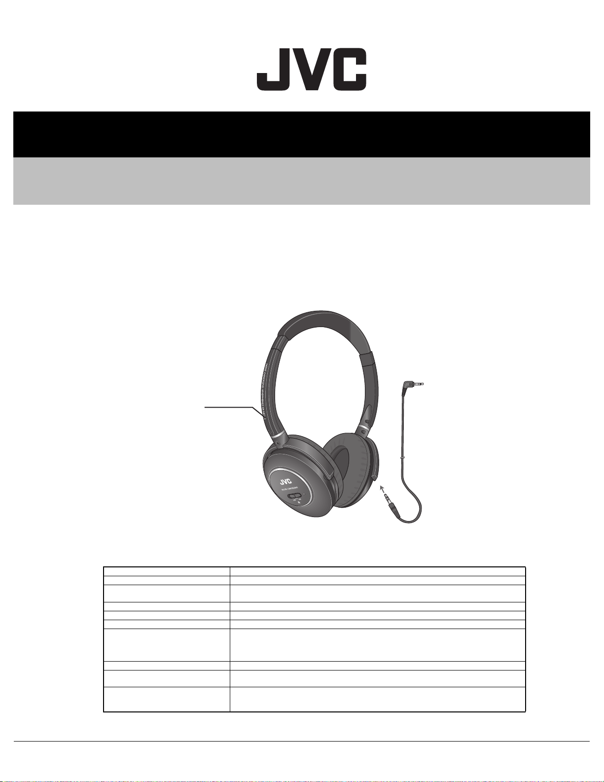
HA-NC250-J, HA-NC250-C,
HA-NC250-E
STEREO HEADPHONES
Model No.
COPYRIGHT © 2007 Victor Company of Japan, Limited
SPECIFICATION
Frequency response 8 Hz - 24, 000 Hz(Power-ON)
Noise reduction More than 16.5 dB at 150 Hz
Sensitivity 102 dB/1 mW (power - ON)
Input impedance 40
Driver unit Ø40 mm
Power supply AAA battery (DC 1.5 V) x 1
Battery life Approx. 20 hours* (using Manganese AAA battery)
Cord length** 1.2 m (3.9 ft) (detachable)
Mass 150 g (5.30 oz) (incl. battery)
Accessories Carrying case x 1, Manganese AAA battery (R03) x 1,
Designs and specifications are subject to change without notice.
COPYRIGHT © 2007 Victor Company of Japan, Limited
100 dB/1 mW (power - OFF)
Ω (power - ON), 96 Ω (power - OFF)
Approx. 50 hours* (using Alkaline AAA battery)
* Varies depending on operating conditions.
* Without ambient noise.
140 g (4.94 oz) (excl. battery)
Cord x 1(1.2 m Ø3.5 Stereo plug
Stereo phone plug adapter 6.3 mm (1/4 inch) x 1
(Lch)
↔Ø3.5 Stereo plug, Dual plug adapter (for in-flight use) x 1,
No.XC063
2007/7
Page 2
SECTION 1
PRECAUTION
This service manual does not describe PRECAUTION.
SECTION 2
SPECIFIC SERVICE INSTRUCTIONS
This service manual does not describe SPECIFIC SERVICE INSTRUCTIONS.
SECTION 3
DISASSEMBLY
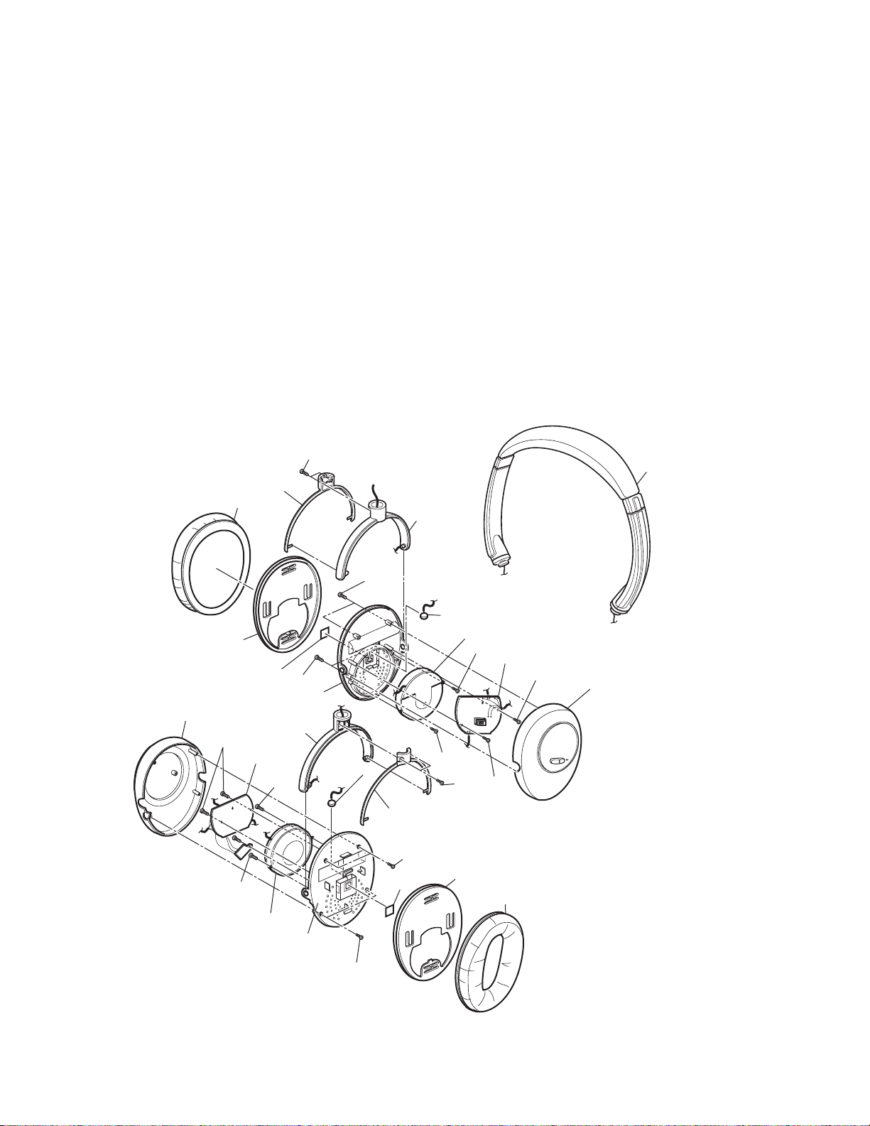
Hanger cover (R)
Ear pad (R)
Ear pad holder (R)
Housing (L)
B
d
b
Seal
Baffle plate (R)
Hanger (L)
Lch board
C
d
c
C
D
A
a
Microphone (L)
b
c
h
Hanger (R)
e
A
g
Hanger cover (L)
A
Seal
f
Microphone (R)
Speaker unit (R)
C
Rch board
g
f
C
B
D
Ear pad holder (L)
Ear pad (L)
Head band
a
h
B
Housing (R)
e
R
1-2 (No.XC063)
Speaker unit (L)
Baffle plate (L)
A
L
Page 3

3.1 Removing the housings(L)/(R)
(1) Remove the ear pads(L)/(R) and ear pad holders(L)/(R).
* When attaching the ear pad holders, be careful as the left and right parts are different.
(2) Remove the eight screws A attaching the housings(L)/(R).
3.2 Removing the Lch board / Rch board
* Remove the housings(L)/(R).
(1) Remove the four screws B attaching the Lch board / Rch board.
(2) Unsolder the wires connected to each board, and then remove each wire.
* When soldering the wires, be careful with the polarity of the wires. (Refer to the wiring diagram)
3.3 Removing the microphones(L)/(R)
• Remove the housings(L)/(R) and the Lch board / Rch board.
(1) Remove the four screws C attaching the speaker units(L)/(R), and then remove the speaker units(L)/(R).
(2) Peel off the seal from the baffle plates(L)/(R), and then remove the microphones(L)/(R).
3.4 Removing the hangers(L)/(R)
• Remove the housings(L)/(R).
• Unsolder the wires connecting from the head band to each board.
(1) Remove the four screws D attaching the hanger covers(L)/(R), and then remove the hanger covers(L)/(R).
(2) Rotate the hanger 90 degrees. (It become the state of "Flat foldable" as shown in the figure below.)
Right Left
Normal Flat foldable
(3) The hanger can be removed by folding and pressing the hanger and head band as shown in the picture.
(4) When attaching, perform the reverse procedure.
Head band
Hanger
(No.XC063)1-3
Page 4

SECTION 4
ADJUSTMENT
4.1 Adjustment of volume
(1) When replacing the "Lch board" or "Rch board", first, check if VR1 is in the "Medium" position as shown in the figure below.
(2) If VR1 is not in the "Medium" position, adjust it to "Medium".
Minimum
VR1
Medium
Rch board and Lch board
Maximum
SECTION 5
TROUBLESHOOTING
5.1 Assembly precautions of power switch knob
When replacing the power switch knob, place the nonwoven fabric provided with the power switch knob over the slide switch
on the Rch board as shown in the picture, and then attach the housing.
Rch board
Nonwoven fabric
(On the slide switch)
Victor company of Japan, Limited
ACCESSORIES CATEGORY 1644, Shimotsuruma, Yamato, Kanagawa 242-8514, Japan
(No.XC063)
Printed in Japan
VPT
 Loading...