

Page 1
SERVICE MANUAL
DV CAMCORDER
GY-DV500U/GY-DV500E
100% recycled paper
The photo shows the GY-DV500 DV camcorder with an optional lens and viewfinder.
COPYRIGHT © 1999 VICTOR COMPANY OF JAPAN, LTD.
No. 60125
November 1999
Page 2

TABLE OF CONTENTS
Section Title Page Section Title Page
Important Safety Precautions
INSTRUCTIONS
SECTION 1 SERVICE CAUTIONS AND DISASSEMBLY
1.1
RESETTING THE POWER CIRCUIT PROTECTION BREAKER ...........
1.2 REMOVING THE EXTERIOR COVERS ..................................... 1-1
1.3 LAYOUTS OF THE MAJOR BOARDS ..................................... 1-2
1.4 REMOVING THE OPTICAL BLOCK ASSEMBLY AND THE
OPTICAL FILTER ASSEMBLY .................................................. 1-3
1.5 REMOVING MAJOR BOARDS FROM THE CAMERA ............. 1-4
1.6 REMOVING THE MAJOR BOARDS FROM THE VCR ............. 1-6
1.7 DISASSEMBLY OF THE VCR UNIT ..........................................1-8
1.8 TAPE EJECTION IN CASE OF EMERGENCY .........................1-10
1.9 CAUTION FOR REPLACING THE DV MAIN BOARD AND VIDEO
SYSCON BOARD ................................................................... 1-12
1.10 FUNCTIONS OF INTERNAL SWITCHES ............................... 1-13
1.11 MODES REQUIRED IN SERVICING ...................................... 1-14
1.12 CHANGING THE COLOR MATRIX SETTING ........................ 1-16
1.13 SERVICE MENU .................................................................... 1-18
1.14 ALARM DETECTION METHODS .......................................... 1-22
1.15 BATTERY POWER DETECTION METHODS ......................... 1-23
1.16 WARNING CODES ................................................................ 1-23
1.17 ANALYSIS OF BLOCK NOISE (SYMPTOMS: POOR VIDEO,
ABSCNCE OF AUDIO) .......................................................... 1-26
1-1
SECTION 2 MECHANISM ADJUSTMENTS
2.1 BERORE ADJUSTMENTS ........................................................ 2-1
2.2 BASICS OF MECHANISM DISASSAMBLY/ASSEMBLY .......... 2-2
2.3 MECHANISM TIMIN CHART ................................................... 2-4
2.4 MAINTENANCE AND INSPECTION OF MAJOR PARTS .......... 2-5
2.5 PERIODICAL MAINTENANCE .................................................. 2-8
2.6 DISASSEMBLY/ASSEMBLY OF MECHANISM ASSEMBLY ..... 2-9
2.7 REPLACEMENT OF MAJOR PARTS ...................................... 2-12
2.8
CONFIRMATION AND ADJUSTMENT OF MECHANISM PHASES........2-27
2.9 MECHANISM DISASSEMBLY/ASSEMBLY SHEET ................ 2-28
2.10 DISASSEMBLY PROCEDURE LIST .......................................2-30
2.11 TORQUE ADJUSTMENTS .................................................... 2-31
2.12 COMPATIBILITY ADJUSTMENT ........................................... 2-32
SECTION 3 ELECTRICAL ADJUSTMENTS
3.1 FLOWCHART OF ELECTRICAL ADJUSTMENTS .................... 3-1
3.2 FUNCTIONS REQUIRED FOR ADJUSTMENTS, SETUP .......... 3-2
3.3 STANDARD SETUP .................................................................. 3-3
3.4 ADJUSTMENT MENU ..............................................................3-3
3.5 CAMERA ADJUSTMENTS ....................................................... 3-5
3.6 VCR ADJUSTMENTS ............................................................. 3-11
3.7 DV ADJUSTMENTS (USING ADJUSTMENT SOFTWARE) .... 3-14
SECTION 4 CHARTS AND DIAGRAMS
4.1 INDEX TO PAGES OF MAIN BOARDS AND CIRCUIT BOARD
LOCATION................................................................................ 4-3
4.2 OVERALL WIRING DIAGRAM (1/2) ......................................... 4-4
• OVERALL WIRING DIAGRAM (2/2) ......................................... 4-5
4.3 ISB/ISG/ISR SCHEMATIC DIAGRAM
4.4 ISB/ISG/ISR CIRCUIT BOARD .................................................. 4-7
4.5 TG(Timing Generator) SCHEMATIC DIAGRAM 14................. 4-8
4.6 TG CIRCUIT BOARD ................................................................ 4-9
4.7 CAM1(CAMera 1) SCHEMATIC DIAGRAM (1/2) 15............ 4-10
• CAM1 SCHEMATIC DIAGRAM (2/2) 15............................... 4-11
4.8 CAM1 CIRCUIT BOARD .........................................................4-12
4.9 CAM2(CAMera 2) SCHEMATIC DIAGRAM (1/3) 16............ 4-14
• CAM2 SCHEMATIC DIAGRAM (2/3) 16............................... 4-15
• CAM2 SCHEMATIC DIAGRAM (3/3)16................................ 4-16
4.10 CAM2 CIRCUIT BOARD ........................................................ 4-17
4.11 PS(Power Supply)1,
PS2 SCHEMATIC DIAGRAM (1/2)
• PS1, PS2 SCHEMATIC DIAGRAM (2/2)
4.12 PS1, PS2 CIRCUIT BOARD ................................................... 4-21
4.13 IF(InterFace), ROM(Read Only Memory)
SCHEMATIC DIAGRAM
4.14 IF, ROM CIRCUIT BOARD ..................................................... 4-23
4.15 SWRU, JOG SCHEMATIC DIAGRAM
4.16 SWF, SWRM, SWRB, SWPW, MIC, BNC SCHEMATIC DIA-
GRAM
4.17 SWRU, JOG, SWF, SWRM, SWRB, SWPW, MIC, BNC, FL
4.18 VIDEO/SYSCON SCHEMATIC DIAGRAM (1/2) 31............. 4-27
• VIDEO/SYSCON SCHEMATIC DIAGRAM (2/2) 31............. 4-28
4.19 VIDEO/SYSCON CIRCUIT BOARD ........................................ 4-29
4.20 AUDIO/LCD SCHEMATIC DIAGRAM (1/2) 32.................... 4-30
• AUDIO/LCD SCHEMATIC DIAGRAM (2/2) 32.................... 4-31
4.21 AUDIO/LCD CIRCUIT BOARD .............................................. 4-32
• AUDIO/LCD CIRCUIT BOARD
4.22 REG(REGulater) SCHEMATIC DIAGRAM 33..................... 4-34
4.23 REG CIRCUIT BOARD........................................................... 4-35
4.24 MOTHER SCHEMATIC DIAGRAM 34............................... 4-36
4.25 MOTHER, AU JUNK CIRCUIT BOARD ................................. 4-37
4.26 AU JUNK SCHEMATIC DIAGRAM 39............................... 4-38
4.27
4.28 CONNECT, REMOTE, XLR, EAR.J, SEN1, SENS2 SCHEMATIC
4.29 OPE, PWR JUNC, CONNECT, REMOTE, XLR, EAR.J, SEN1,
4.30 VTR UNIT OVERALL WIRING DIAGRAM ............................. 4-42
4.31 DV MAIN SCHEMATIC DIAGRAM (1/7) 10........................ 4-43
• DV MAIN SCHEMATIC DIAGRAM (2/7) 10........................ 4-44
• DV MAIN SCHEMATIC DIAGRAM (3/7) 10........................ 4-45
• DV MAIN SCHEMATIC DIAGRAM (4/7) 10........................ 4-46
• DV MAIN SCHEMATIC DIAGRAM (5/7) 10........................ 4-47
• DV MAIN SCHEMATIC DIAGRAM (6/7) 10........................ 4-48
• DV MAIN SCHEMATIC DIAGRAM (7/7) 10........................ 4-49
4.32 DV MAIN CIRCUIT BOARD ................................................... 4-50
• DV MAIN CIRCUIT BOARD (FOR SERIAL No.⳯⳯⳯⳯0332
4.33 PR & MDA SCHEMATIC DIAGRAM (1/2) 01...................... 4-52
• PR(Pre Rec) & MDA(Motor Drive Amp.) SCHEMATIC DIAGRAM
23/ 24/ 25/ 26/ 27/ 28
CIRCUIT BOARD ................................................................... 4-26
(FOR SERIAL No.⳯⳯⳯⳯0732 AND AFTER OF GY-DV500U,⳯⳯⳯⳯0840
AND AFTER OF GY-500E) ........................................................................... 4-32-2
PWR JUNC, OPE(OPEration) SCHEMATIC DIAGRAM
DIAGRAM
SENS2 CIRCUIT BOARD ....................................................... 4-41
AND AFTER OF GY-DV500U, ⳯⳯⳯⳯0545 AND AFTER OF GY-
DV500E) ............................................................................ 4-50-2
(2/2) 01............................................................................... 4-53
42/ 38/ 40/ 43/ 36/ 37
21/ 19
11/ 12/ 13
17/ 18
17/ 18
....................................... 4-22
22/ 20
................................ 4-25
.......................... 4-40
.............. 4-6
......................... 4-19
................. 4-20
................... 4-24
41/ 35
..... 4-39
Page 3

4.34 PR & MDA CIRCUIT BOARD ................................................ 4-54
4.35 ROM, CONN. SCHEMATIC DIAGRAM
4.36 DCDC SCHEMATIC DIAGRAM 02..................................... 4-56
4.37 DCDC, ROM, CONN. CIRCUIT BOARD ................................ 4-57
4.38 IS &TG BLOCK DIAGRAM (G channel) ................................. 4-58
4.39 CAM1 BOARD BLOCK DIAGRAM ........................................ 4-59
4.40 CAM2 BOARD BLOCK DIAGRAM ........................................ 4-60
4.41 IF, SWF, SWRU BLOCK DAIGRAM .......................................4-61
4.42 SYSCON BLOCK DIAGRAM ................................................. 4-62
4.43 LCD BLOCK DIAGRAM......................................................... 4-63
4.44 VIDEO BLOCK DIAGRAM ..................................................... 4-64
4.45 REG BLOCK DIAGRAM ........................................................ 4-64
4.46 AUDIO BLOCK DIAGRAM .................................................... 4-65
4.47 DV BLOCK DIAGRAM 1/2 ..................................................... 4-66
• DV BLOCK DIAGRAM 2/2 .....................................................4-67
4.48 IC BLOCK DIAGRAM ........................................................... 4-68
03/ 04
................. 4-55
SECTION 5 EXPLODED VIEW AND PARTS LIST
5.1 CAMERA HEAD ASSEMBLY M1............................................ 5-3
5.2 CABINET ASSEMBLY M2....................................................... 5-4
5.3 RIGHT SIDE COVER ASSEMBLY M3...................................... 5-7
5.4 CHASSIS ASSEMBLY M4....................................................... 5-8
5.5 VTR UNIT ASSEMBLY M5.................................................... 5-11
5.6 MECHANISM ASSEMBLY M6.............................................. 5-12
SECTION 6 ELECTRICAL PARTS LIST
6.1 PR & MDA BOARD ASSEMBLY PARTS LIST 01................... 6-2
6.2 DCDC BOARD ASSEMBLY PARTS LIST 02.......................... 6-3
6.3 ROM BOARD ASSEMBLY PARTS LIST 03............................ 6-4
6.4 CONN. BOARD ASSEMBLY PARTS LIST 04......................... 6-4
6.5 DV MAIN BOARD ASSEMBLY PARTS LIST 10..................... 6-5
6.6 ISB BOARD ASSEMBLY PARTS LIST 11............................ 6-11
6.7 ISG BOARD ASSEMBLY PARTS LIST 12............................. 6-11
6.8 ISR BOARD ASSEMBLY PARTS LISTT 13........................... 6-12
6.9 TG BOARD ASSEMBLY PARTS LISTT 14........................... 6-12
6.10 CAM1 BOARD ASSEMBLY PARTS LIST 15....................... 6-13
6.11 CAM2 BOARD ASSEMBLY PARTS LIST 16....................... 6-17
6.12 PS1 BOARD ASSEMBLY PARTS LIST 17........................... 6-21
6.13 PS2 BOARD ASSEMBLY PARTS LIST 18........................... 6-21
6.14 ROM BOARD ASSEMBLY PARTS LIST 19......................... 6-22
6.15 JOG BOARD ASSEMBLY PARTS LIST 20.......................... 6-22
6.16 IF BOARD ASSEMBLY PARTS LIST 21.............................. 6-23
6.17 SWRU BOARD ASSEMBLY PARTS LIST 22...................... 6-23
6.18 SWF BOARD ASSEMBLY PARTS LIST 23......................... 6-24
6.19 SWRM BOARD ASSEMBLY PARTS LIST 24...................... 6-24
6.20 SWRB BOARD ASSEMBLY PARTS LIST 25....................... 6-24
6.21 SWPW BOARD ASSEMBLY PARTS LIST 26...................... 6-24
6.22 MIC BOARD ASSEMBLY PARTS LIST 27.......................... 6-25
6.23 BNC BOARD ASSEMBLY PARTS LIST 28.......................... 6-25
6.24 VIDEO/SYSCON BOARD ASSEMBLY PARTS LIST 31....... 6-25
6.25 AUDIO/LCD BOARD ASSEMBLY PARTS LIST 32.............. 6-28
6.26 REG BOARD ASSEMBLY PARTS LIST 33.......................... 6-31
6.27 MOTHER BOARD ASSEMBLY PARTS LIST 34.................. 6-33
6.28 OPE BOARD ASSEMBLY PARTS LIST 35.......................... 6-33
6.29 SEN1 BOARD ASSEMBLY PARTS LIST 36........................ 6-33
6.30 SENS2 BOARD ASSEMBLY PARTS LIST 37...................... 6-33
6.31 REMOTE BOARD ASSEMBLY PARTS LIST 38.................. 6-33
6.32 AU JUNK BOARD ASSEMBLY PARTS LIST 39.................. 6-34
6.33 XLR BOARD ASSEMBLY PARTS LIST 40........................... 6-35
6.34 PWR JUNC BOARD ASSEMBLY PARTS LIST 41............... 6-35
6.35 CONNECT BOARD ASSEMBLY PARTS LIST 42................ 6-35
6.36 EAR.J BOARD ASSEMBLY PARTS LIST 43....................... 6-35
SECTION 7 PACKING
7.1 PACKING ASSEMBLY M7....................................................... 7-1
7.2 FACTORY SETTING OF SWITCH AND VR ...............................7-2
SECTION 8 DESCRIPTION OF NEW CIRCUITRY
8.1 OUTLINE OF DV ....................................................................... 8-1
8.2 MAJOR SIGNAL PROCESSING OPERATIONS OF DV ............ 8-6
8.3 VIDEO/AUDIO SIGNAL PROCESSING IN RECORDING
CIRCUITRY ............................................................................... 8-7
VIDEO/AUDIO SIGNAL PROCESSING IN PLAYBACK CIRCUITRY ..
8.4
8.5 CAPSTAN SERVO................................................................... 8-20
8.6 DRUM SERVO ........................................................................ 8-22
8-18
SECTION 9 CIRCUIT DESCRIPTION
9.1 CAMERA HEAD CIRCUITRY .................................................... 9-1
9.2 DVC CIRCUIT ........................................................................... 9-4
9.3 MECHANISM OPERATION DESCRIPTION ............................ 9-20
9.4 EXPLANATION OF NEW FUNCTIONS ................................... 9-26
Page 4
Important Safety Precautions
Connector
Metal sleeve
Prior to shipment from the factory, JVC products are strictly inspected to conform with the recognized product safety and electrical codes
of the countries in which they are to be sold. However, in order to maintain such compliance, it is equally important to implement the
following precautions when a set is being serviced.
Precautions during Servicing
1. Locations requiring special caution are denoted by labels and
inscriptions on the cabinet, chassis and certain parts of the
product. When performing service, be sure to read and comply with these and other cautionary notices appearing in the
operation and service manuals.
2. Parts identified by the
critical for safety.
Replace only with specified part numbers.
Note: Parts in this category also include those specified to com-
ply with X-ray emission standards for products using
cathode ray tubes and those specified for compliance
with various regulations regarding spurious radiation
emission.
3. Fuse replacement caution notice.
Caution for continued protection against fire hazard.
Replace only with same type and rated fuse(s) as specified.
4. Use specified internal wiring. Note especially:
1) Wires covered with PVC tubing
2) Double insulated wires
3) High voltage leads
5. Use specified insulating materials for hazardous live parts.
Note especially:
1) Insulation Tape 3) Spacers 5) Barrier
2) PVC tubing 4) Insulation sheets for transistors
6. When replacing AC primary side components (transformers,
power cords, noise blocking capacitors, etc.) wrap ends of
wires securely about the terminals before soldering.
symbol and shaded ( ) parts are
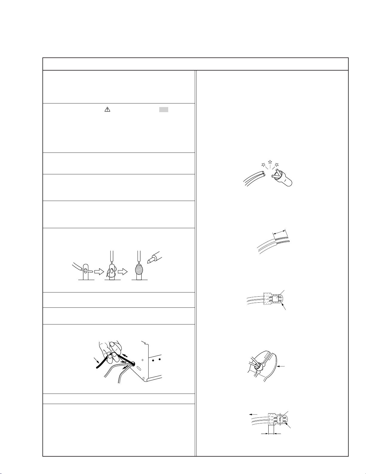
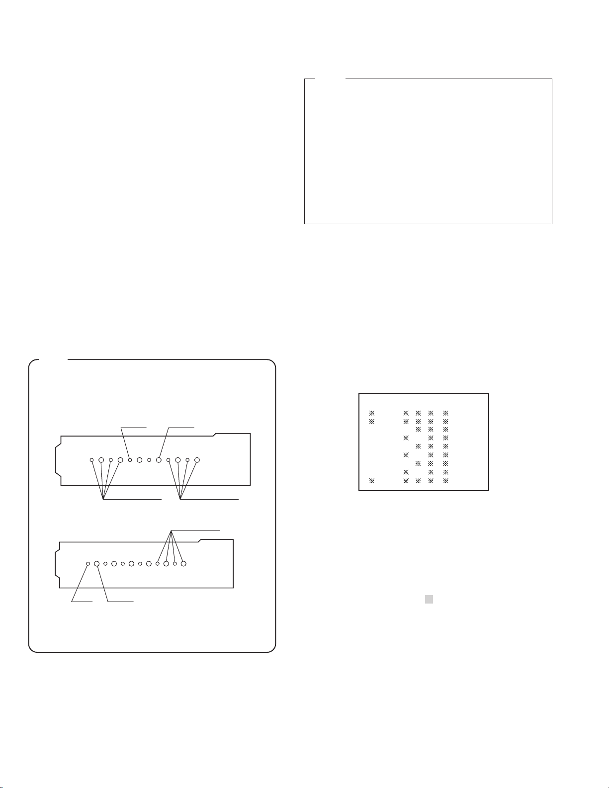
12. Crimp type wire connector
In such cases as when replacing the power transformer in sets
where the connections between the power cord and power
transformer primary lead wires are performed using crimp type
connectors, if replacing the connectors is unavoidable, in order to prevent safety hazards, perform carefully and precisely
according to the following steps.
1) Connector part number : E03830-001
2) Required tool : Connector crimping tool of the proper type
which will not damage insulated parts.
3) Replacement procedure
(1) Remove the old connector by cutting the wires at a point
close to the connector.
Important : Do not reuse a connector (discard it).
cut close to connector
Fig.3
(2) Strip about 15 mm of the insulation from the ends of
the wires. If the wires are stranded, twist the strands to
avoid frayed conductors.
15 mm
7. Observe that wires do not contact heat producing parts
8. Check that replaced wires do not contact sharp edged or
9. When a power cord has been replaced, check that 10-15 kg of
10. Also check areas surrounding repaired locations.
11. Products using cathode ray tubes (CRTs)
Fig.1
(heatsinks, oxide metal film resistors, fusible resistors, etc.)
pointed parts.
force in any direction will not loosen it.
Power cord
Fig.2
In regard to such products, the cathode ray tubes themselves,
the high voltage circuits, and related circuits are specified for
compliance with recognized codes pertaining to X-ray emission.
Consequently, when servicing these products, replace the cathode ray tubes and other parts with only the specified parts.
Under no circumstances attempt to modify these circuits.
Unauthorized modification can increase the high voltage value
and cause X-ray emission from the cathode ray tube.
Fig.4
(3) Align the lengths of the wires to be connected. Insert
the wires fully into the connector.
Fig.5
(4) As shown in Fig.6, use the crimping tool to crimp the
metal sleeve at the center position. Be sure to crimp fully
to the complete closure of the tool.
1.25
2.0
5.5
Fig.6
(5) Check the four points noted in Fig.7.
Not easily pulled free
Wire insulation recessed
more than 4 mm
Fig.7
Crimping tool
Crimped at approx. center
of metal sleeve
Conductors extended
1
Page 5
p
Safety Check after Servicing
Examine the area surrounding the repaired location for damage or deterioration. Observe that screws, parts and wires have been
returned to original positions, Afterwards, perform the following tests and confirm the specified values in order to verify compliance with safety standards.
1. Insulation resistance test
Confirm the specified insulation resistance or greater between power cord plug prongs and
externally exposed parts of the set (RF terminals, antenna terminals, video and audio input
and output terminals, microphone jacks, earphone jacks, etc.). See table 1 below.
2. Dielectric strength test
Confirm specified dielectric strength or greater between power cord plug prongs and exposed
accessible parts of the set (RF terminals, antenna terminals, video and audio input and output
terminals, microphone jacks, earphone jacks, etc.). See table 1 below.
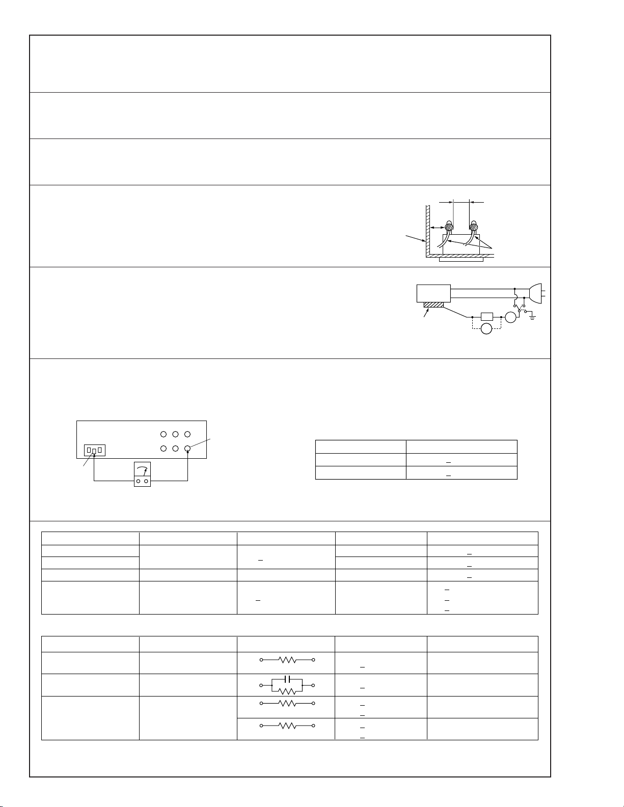
3. Clearance distance
When replacing primary circuit components, confirm specified clearance distance (d), (d’) between soldered terminals, and between terminals and surrounding metallic parts. See table 1
below.
Chassis
Fig. 8
4. Leakage current test
Confirm specified or lower leakage current between earth ground/power cord plug prongs
and externally exposed accessible parts (RF terminals, antenna terminals, video and audio
input and output terminals, microphone jacks, earphone jacks, etc.).
Measuring Method : (Power ON)
Insert load Z between earth ground/power cord plug prongs and externally exposed accessible parts. Use an AC voltmeter to measure across both terminals of load Z. See figure 9 and
following table 2.
5. Grounding (Class 1 model only)
Confirm specified or lower grounding impedance between earth pin in AC inlet and externally exposed accessible parts (Video in,
Video out, Audio in, Audio out or Fixing screw etc.).
Measuring Method:
Connect milli ohm meter between earth pin in AC inlet and exposed accessible parts. See figure 10 and grounding specifications.
AC inlet
Earth pin
Exposed accessible part
Grounding Specifications
Region
USA & Canada
Europe & Australia
Externally
exposed
accessible
Grounding Impedance (Z)
d
d'
art
≤
Z 0.1 ohm
≤
Z 0.5 ohm
Power cord,
primary wire
Z
V
Fig. 9
ab
c
A
Milli ohm meter
Fig. 10
AC Line Voltage
100 V
100 to 240 V
110 to 130 V
110 to 130 V
200 to 240 V
100 V
110 to 130 V
110 to 130 V
220 to 240 V
Note: These tables are unofficial and for reference only. Be sure to confirm the precise values for your particular country and locality.
Region
Japan R 1 MΩ/500 V DC
USA & Canada
Europe & Australia R 10 MΩ/500 V DC
Region Load Z
Japan
USA & Canada
Europe & Australia
Table 2 Leakage current specifications for each region
Insulation Resistance (R)
≤
–
≤
Table 1 Specifications for each region
1 kΩ
0.15 µF
1.5 kΩ
2 kΩ
50 kΩ
Dielectric Strength
AC 1 kV 1 minute
AC 1.5 kV 1 miute
AC 900 V 1 minute
AC 3 kV 1 minute
AC 1.5 kV 1 minute
i 1 mA rms Exposed accessible parts
i 0.5 mA rms
i 0.7 mA peak
i 2 mA dc
i 0.7 mA peak
i 2 mA dc
≤
≤
≤
≤
≤
≤
(Class 2)
(Class 1)
Clearance Distance (d), (d')
≤
d, d' 3 mm
≤
d, d' 4 mm
≤
d, d' 3.2 mm
≤
d 4 mm
≤
d' 8 mm (Power cord)
≤
d' 6 mm (Primary wire)
a, b, cLeakage Current (i)AC Line Voltage
Exposed accessible parts
Antenna earth terminals
Other terminals
2
Page 6
2
2
4
SECTION 1
1
SERVICE CAUTIONS AND DISASSEMBLY
1.1 RESETTING THE POWER CIRCUIT PROTECTION
BREAKER
This unit employs a power circuit protection breaker in place of
a fuse to disconnect from the main power and to thus protect
the internal circuitry from damage caused by any current overload. The power can be re-connected by resetting the breaker.
To prevent any complications resulting from the failure, check the cause of the shutdown and repair it
before resetting the circuit breaker.
(1) Switch OFF the POWER of this unit as well as that of any
equipment supplying power to it.
(2) The circuit breaker
Press the BREAK button to re-connect the power line.
is located below the VCR at the rear.
Å
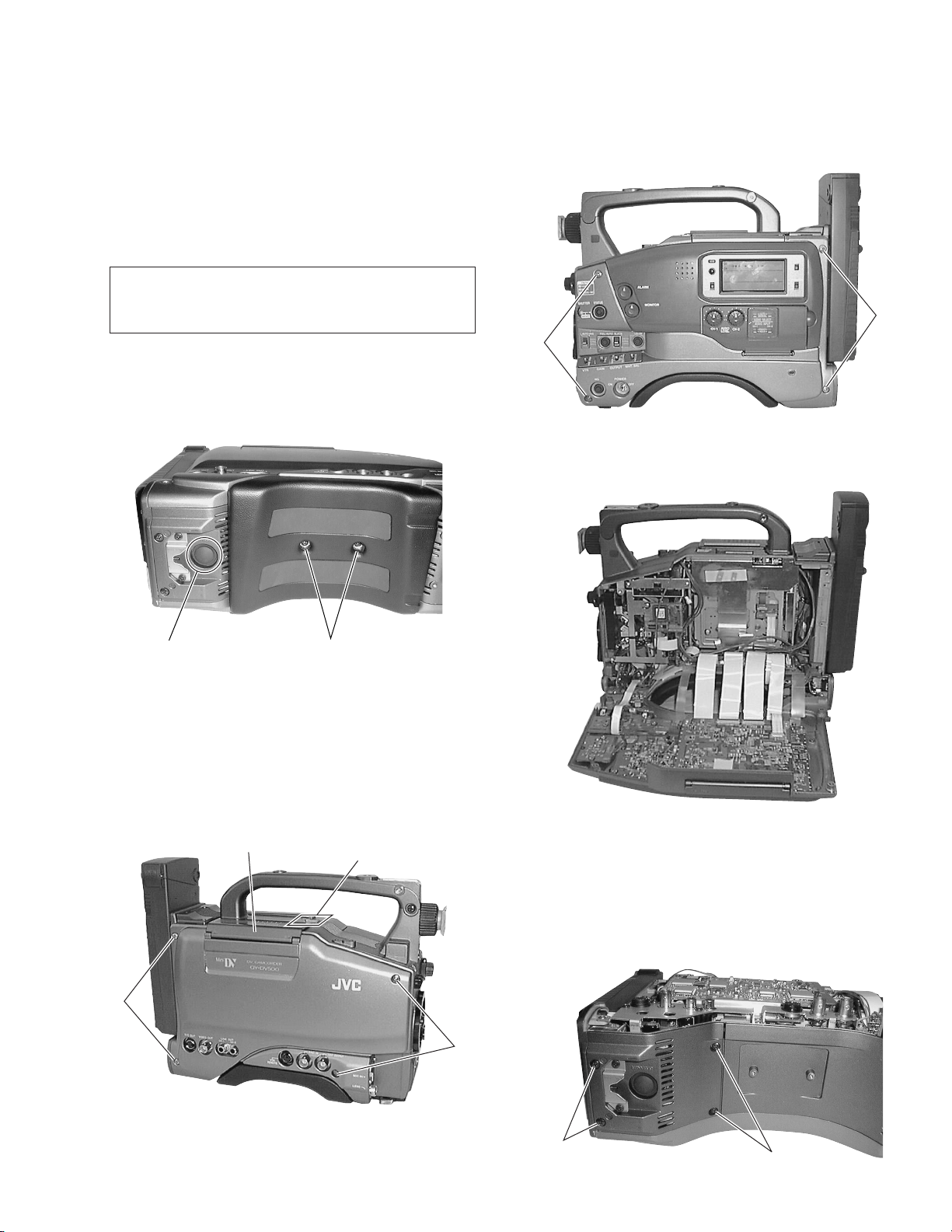
1.2.2 Opening the Right Side Cover
(1) Loosen the 4 screws
Fig. 1-2-2(1) Opening the Right Side Cover
(2) Flip open the right side cover toward the front.
2
.
Å
Fig. 1-1 Position of the Circuit Breaker
1.2 REMOVING THE EXTERIOR COVERS
1.2.1 Removing the Left Side Cover
(1) Open the cassette door by pressing the EJECT switch.
(2) Loosen the 4 screws
Cassette cover
and remove the left side cover.
1
3
EJECT switch
1
Fig. 1-2-2(2) View of the Opened Right Side Cover
1.2.3 Removing the Bottom Cover
(1) Remove the left side cover (see section 1.2.1).
(2) Remove the 2 screws
Fig. 1-1).
(3) Remove the 4 screws
and remove the shoulder pads (see
3
and remove the bottom cover.
4
Fig. 1-2-1 Removing the Left Side Cover
Fig. 1-2-3 Removing the Bottom Cover
4
1-1
Page 7
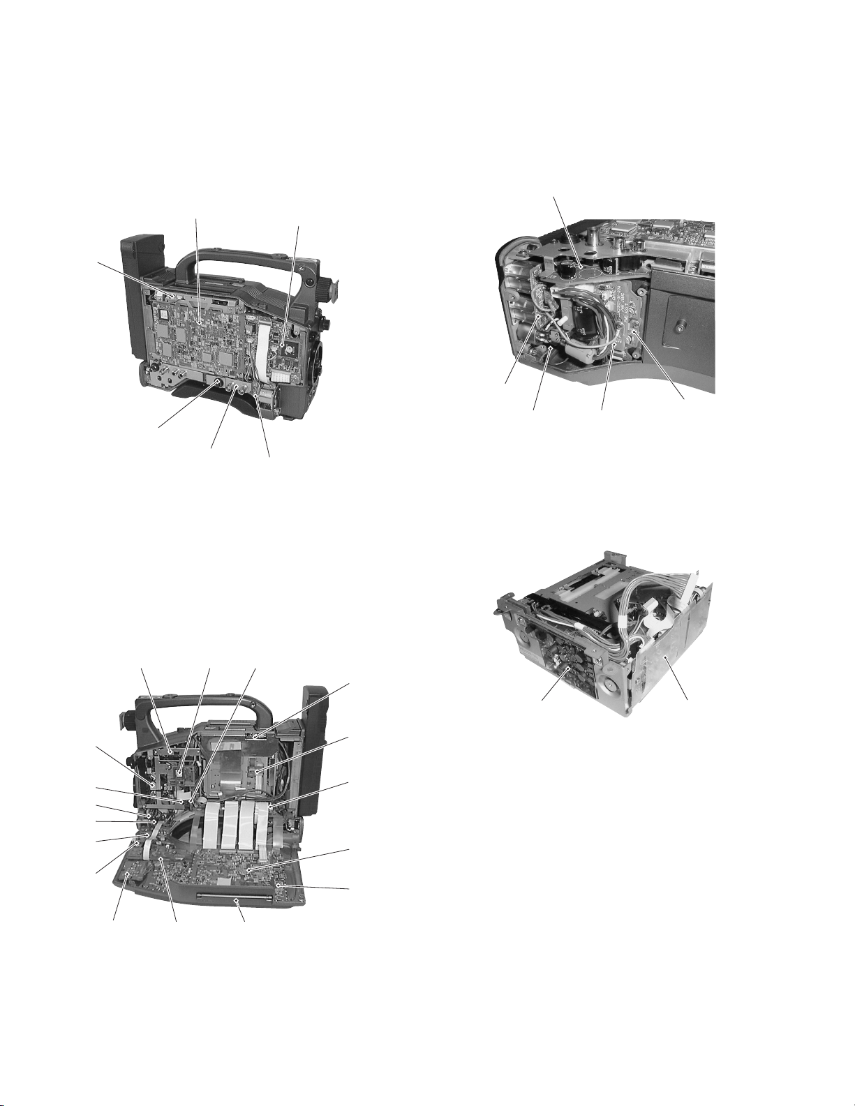
1.3 LAYOUTS OF THE MAJOR BOARDS
On the side of the left-hand side cover
03ROM
10DV MAIN
37SENS2
38REMOTE
28BNC
27MIC
16CAM2
On the side of the bottom cover
42CONNECT
40XLR
43EAR.J
41PWR JUNC
VCR section
39AU JUNK
On the side of the right-hand side cover
19ROM 15CAM1
35OPE 22SWRU 20JOG
11ISB
12ISG
13ISR
14TG
23SWF
21IF
25SWPB
26SWPW
24SWRM
17PS1, 18PS2
36SEN1
04CONN.
34MOTHER
31VIDEO/SYSCON
32AUDIO/LCD
02DCDC
01PR & MDA
1-2
Page 8
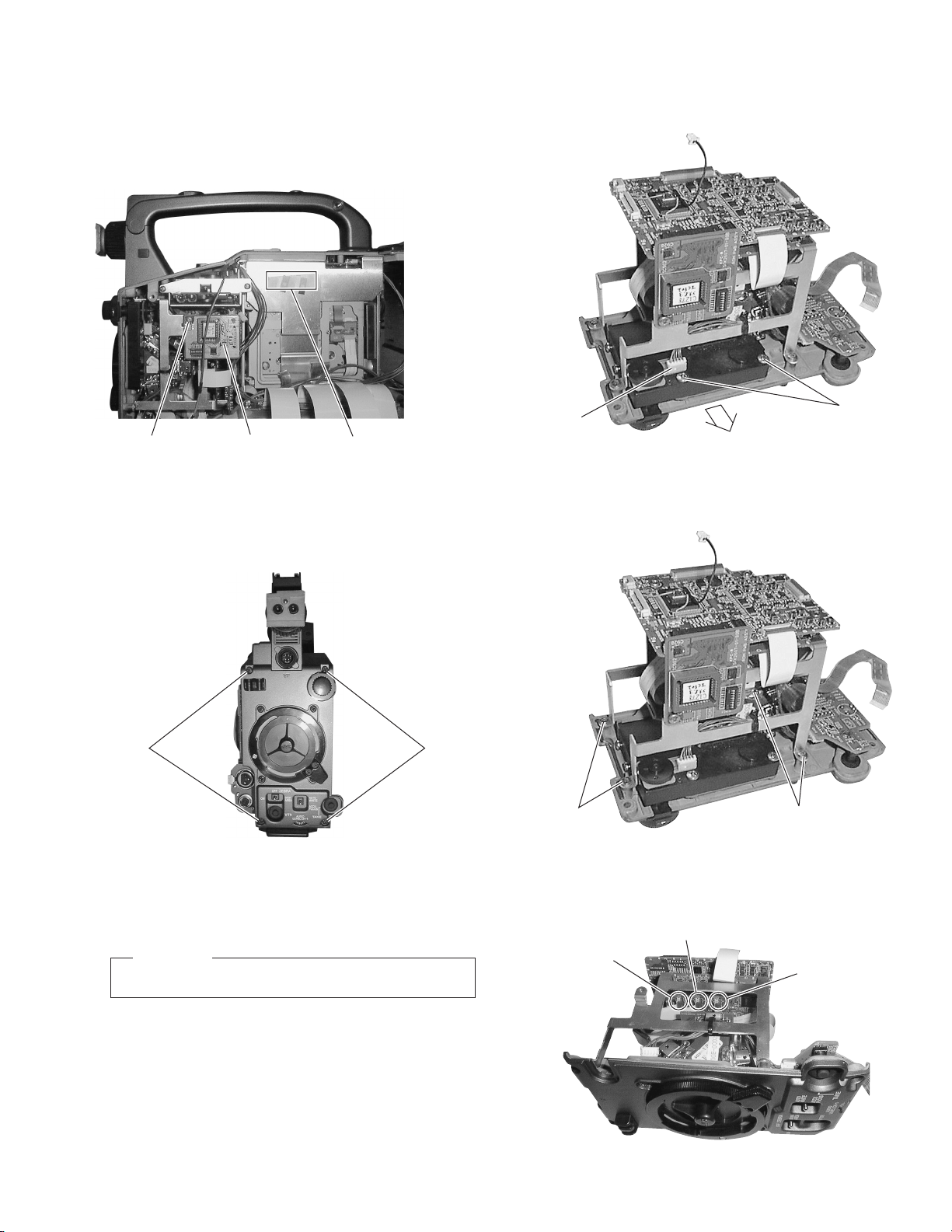
1.4 REMOVING THE OPTICAL BLOCK ASSEMBLY AND
2
3
Å
THE OPTICAL FILTER ASSEMBLY
(1) Remove the right side cover (see section 1.2.2).
(2) Remove the screw
retaining the ROM board.
1
(5) Loosen the 2 screws
(6) Remove the optical filter assembly in the direction of the
arrow.
and remove the connector Å.
3
1
(3) Remove the 4 screws
ROM board
Fig. 1-4-1
.
2
S.S.F. ID label
for VIDEO/SYSCON board
2
Fig. 1-4-2
(4) Pull out the optical block assembly and the front panel to-
gether toward the front.
CAUTION
Be careful not to damage the boards or the FC cables.
Fig. 1-4-3
(7) Remove the 4 screws
board mounting brackets.
4
(8) Flip open CN11, CN12 and CN13 and unplug the flexible
cables.
CN11
and remove the TG board and CP
4
4
Fig. 1-4-4(1)
CN12
CN13
Fig. 1-4-4(2)
1-3
Page 9
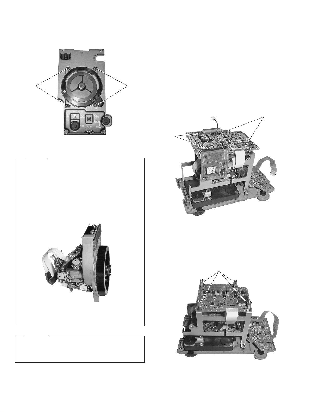
(9) Remove the 4 screws
sembly from the front panel.
and separate the optical block as-
5
55
Fig. 1-4-5
NOTES
• The CCDs are bonded precisely to the prism. In case of
trouble with a CCD, it is not possible to replace an individual CCD, but the entire optical block assembly should
be replaced.
• The optical block assembly supplied as a service part
(SCM1049-N0A (NTSC)/P0A (PAL)) is not equipped with the
DR board. When replacing the optical block assembly, attach the surrounding PC boards to the new assembly before mounting it in the camera.
1.5 REMOVING MAJOR BOARDS FROM THE
CAMERA
1.5.1 Removing the CP and TG Boards.
(1) Remove the right side cover (see section 1.2.2).
(2) Remove the 4 screws retaining the front panel (see section
1.4.3).
(3) Pull out the optical block assembly and the front panel to-
gether toward the front.
(4) Remove the screw retaining the ROM board. Now the ROM
board can be removed.
(5) Remove the 4 screws
. Now the CP board can be removed.
1
1
1
Fig. 1-5-1(1)
Fig. 1-4-6 Optical Block Assembly for Servicing
CAUTION
When mounting the optical block assembly in the camera,
take care of the positioning of the wire assembly. A malfunction may occur if a wire is somehow caught up.
(6) Remove the CP board, then remove the 4 stud screws 4.
Now the TG board is disengaged from the stay.
(7) Unplug the flexible cables connecting the IS boards and the
TG board. Now the TG board can be removed.
4
Fig. 1-5-1(2)
1-4
Page 10
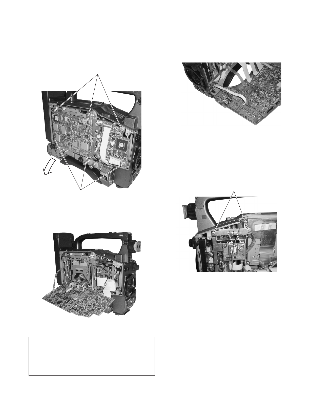
1.5.2 Removing the CAM1 Board
(1) Remove the left side cover (section 1.2.1).
(2) Remove the 6 screws
(3) The DV MAIN board on the VCR side and the CAM2 board
are connected by a board-to-board connector. Open the two
boards together in the direction of the arrow.
2
.
2
1.5.3 Removing the SW Boards
(1) Open the right side cover (see section 1.2.2).
(2) The JOG, SWRU, SWRM, SWPW and SWRB boards are
attached on the right side cover. Remove them as required.
Fig. 1-5-3
1.5.4 Removing the PS 1 & 2 board.
(1) Open the right side cover (see section 1.2.2).
(2) Remove the 2 screws
(3) Pull out the PS 1 & 2 board, along the guide rail in the direc-
tion of the arrow.
retaining the PS 1 & 2 board.
3
2
Fig. 1-5-2(1)
(4) The opened boards can be secured by fitting them into the
notches on the VCR side frame as shown in the figure.
Fig. 1-5-2(2)
3
Fig. 1-5-4
The operation of the VCR can be confirmed when the
circuit boards are tilted.
When the circuit boards are tilted, take care that the
electrical circuitry on each board is not short-circuited
by the BNC connector located below the board.
1-5
Page 11
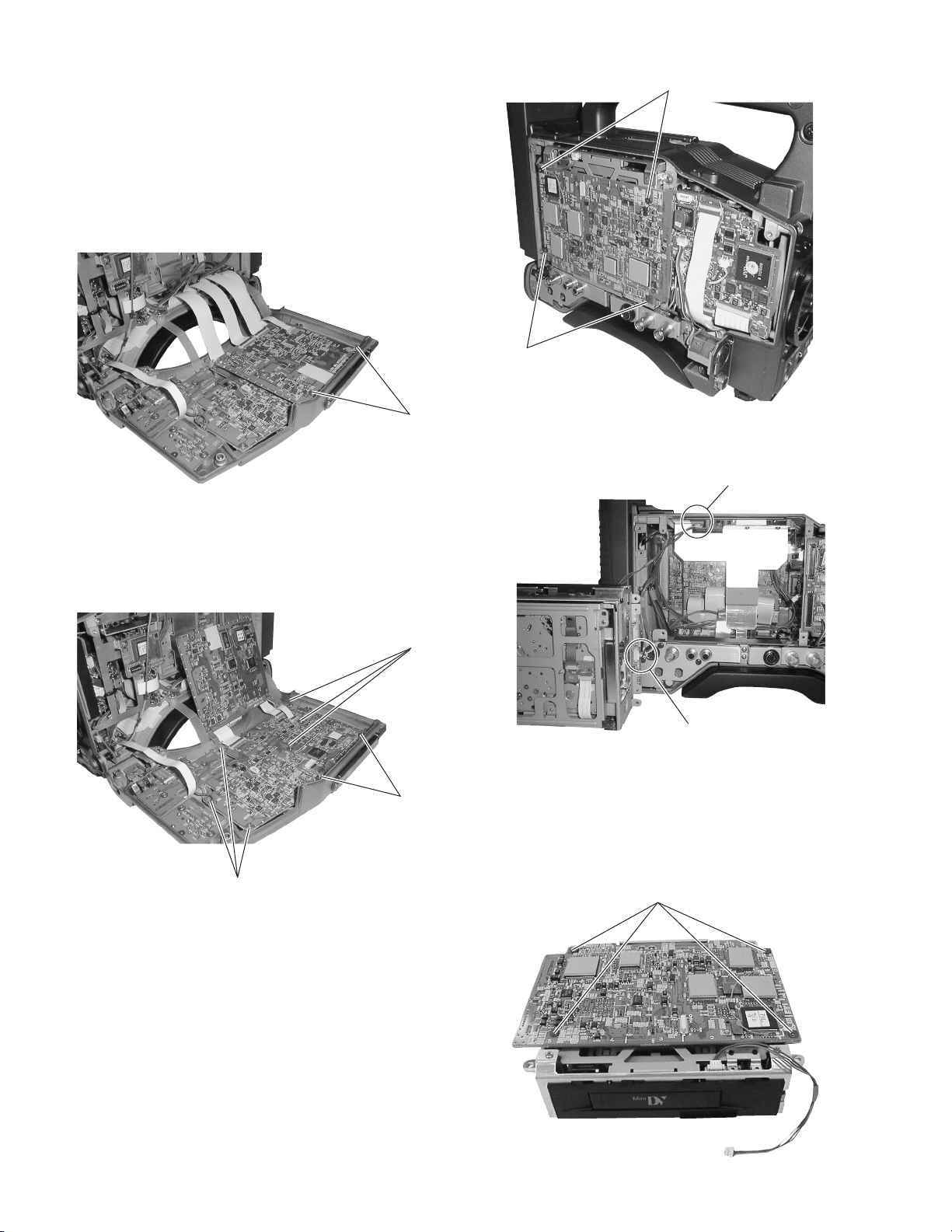
1.6 REMOVING THE MAJOR BOARDS FROM THE VCR
1.6.1 Removing the VIDEO/SYSCON Board and Audio/
LCD Board
(1) Open the right side cover (see section 1.2.2).
The VIDEO/SYSCON board is clamped to the right side cover.
(2) Remove the 2 screws
can be removed.
. Now the VIDEO/SYSCON board
1
4
4
1
Fig. 1-6-1(1)
(3) After removing the VIDEO/SYSCON board, remove the 6
screws
be removed.
and 2 studs 3. Now the AUDIO/LCD board can
2
2
3
2
Fig. 1-6-1(2)
Fig. 1-6-2(1)
(4) Remove the EJECT switch wire
.
ı
and power supply wire
Å
Å
ı
Fig. 1-6-2(2)
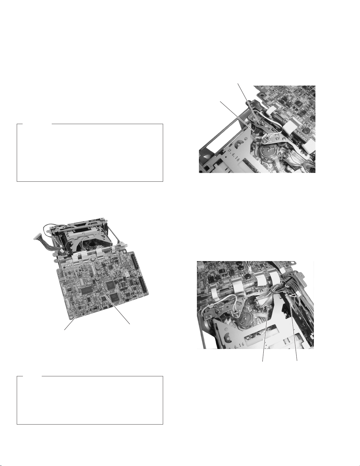
1.6.3 Removing the DV MAIN Board
(1) Remove the VCR unit (see section 1.6.2).
(2) Remove the 4 screws
(3) Now the DV MAIN board can be removed.
5
.
5
1.6.2 Removing the VCR Unit
(1) Remove the left side cover (see section 1.2.1).
(2) Remove the 4 screws
(3) Pull out the VCR unit gently in the direction of the arrow. As
the VCR unit is connected to the CAM2 board with a boardto-board connector, disconnect it gently.
1-6
4
.
Fig. 1-6-3(1)
Page 12
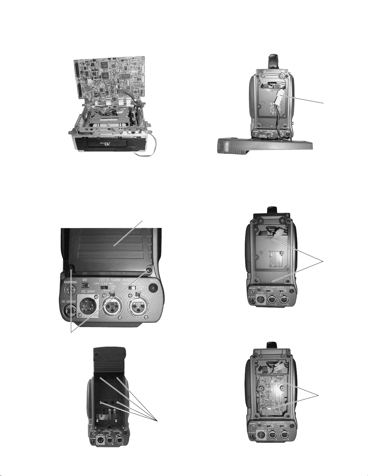
(4) After removing the DV MAIN board, leave it standing up by
fitting it into the notches on the unit frame, as shown in the
figure.
(3) Unplug the power cable that supplies power from the bat-
tery case to the main unit, from the connector
Ç
.
Ç
Fig. 1-6-3(2)
1.6.4 Removing the Battery Case
(1) Remove the 2 screws 1 and remove the rear cover of the
battery case.
(2) Remove the 4 screws
the main unit.
and remove the battery case from
2
Rear cover
1
Fig. 1-6-4(1)
Fig. 1-6-4(3)
1.6.5 Removing the REG Board
(1) Remove the battery case (see section 1.6.4).
(2) Remove the 2 screws
(3) Remove the 2 screws
and remove the panel.
3
Fig. 1-6-5(1)
and remove the REG board.
4
3
Fig. 1-6-4(2)
4
2
Fig. 1-6-5(2)
1-7
Page 13
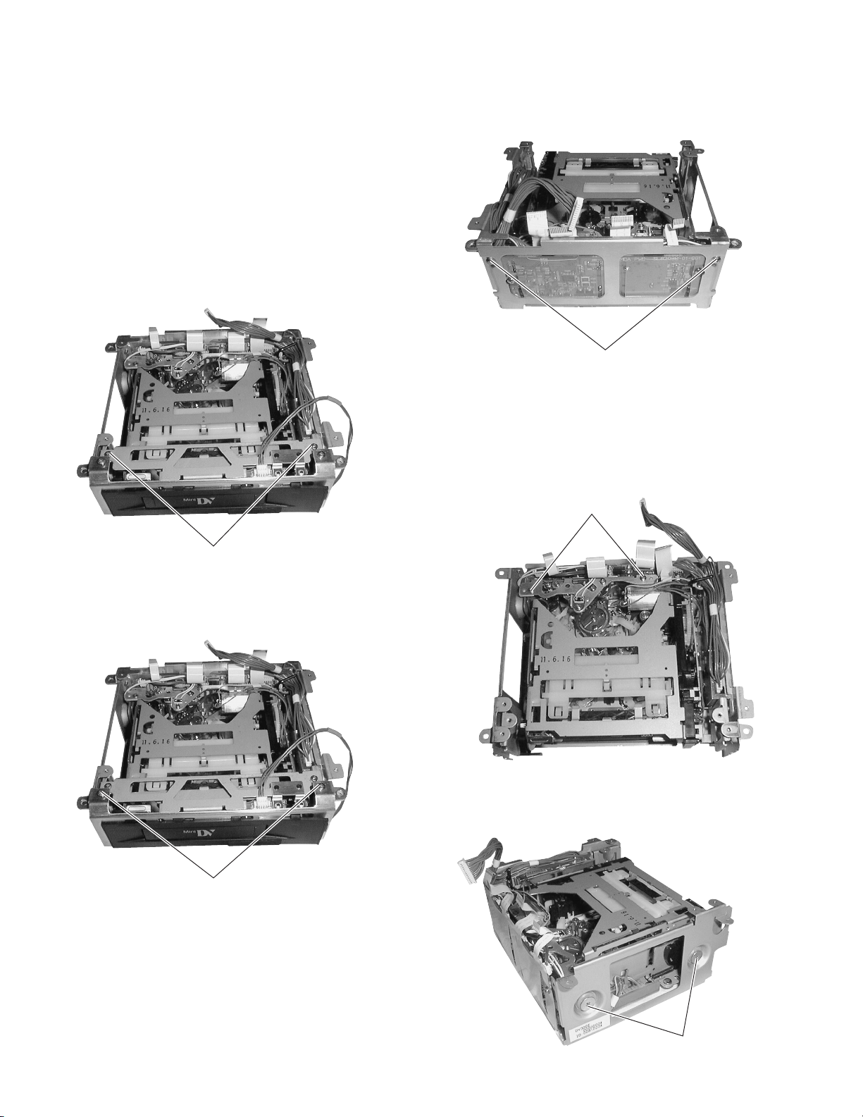
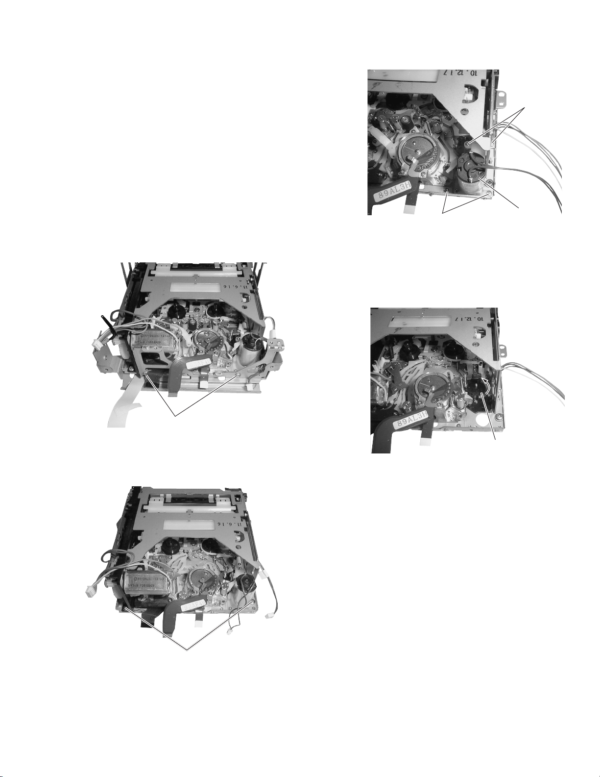
1.7 DISASSEMBLY OF THE VCR UNIT
The mechanism unit incorporated in the unit can be disassembled as described below. Note that the following description
deals only with the method of removing the mechanism unit
from the VCR unit.
1.7.1 Disassembling the Front Part of the Unit
(1) Remove the VCR unit from the camera (see section 1.6.2).
(2) Remove the DV MAIN board (see section 1.6.3).
(3) Remove the 2 screws
cover. The cover of the cassette insertion slot will come out
together with it.
and remove the stay on the front
1
1.7.2 Disassembling the Rear Part of the Unit
(1) Remove the 2 screws
and remove the rear side stay.
3
3
Fig. 1-7-2(1)
(4) Remove the 2 screws
1
Fig. 1-7-1(1)
and remove the front stay.
2
(2) Remove the 2 screws
During this operation, be careful not to apply excessive force
to the wire that is connected between the active head cleaner
assembly and CN609 on the PR & MDA boards.
and remove the active head cleaner.
4
4
Fig. 1-7-2(2)
(3) Remove the 2 screws
and remove the side stays.
5
1-8
2
Fig. 1-7-1(2)
5
Fig. 1-7-2(3)
Page 14
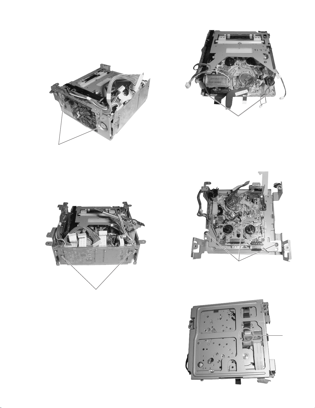
(4) Insulators (blue) are attached to the retaining screws. Be
sure to attach the insulators when re-assembling the side
stays.
(5) The side stays to both sides are attached in the same way.
Remove the 2 screws
and remove the side stays.
6
6
Fig. 1-7-3
6
Fig. 1-7-2(4)
(6) After removing the rear stays and side stays (left and right),
remove the 2 screws 7 then remove the PR & MDA board.
When removing the PR & MDA boards, be careful not to
damage the wires and FFCs connecting them to the deck
assembly housing motor and power supply board.
7
Fig. 1-7-2(5)
1.7.4 Removing the Mechanism Unit
(1) Remove the 3 screws 8. This allows the mechanism unit
to be removed from the stays When it is required to disassemble the mechanism unit itself, see SECTION 2.
8
Fig. 1-7-4(1)
(2) When the remove the mechanism unit completely, also re-
move the connector
from the rear.
Å
1.7.3 Removing the Cassette Housing Assembly
(1) Remove the 2 screws
assembly.
and remove the cassette housing
6
Å
Fig. 1-7-4(2)
1-9
Page 15
1.8 TAPE EJECTION IN CASE OF EMERGENCY
When the cassette tape cannot be ejected normally, take it out
by the following methods.
1.8.1 Tape Ejection Using Forced Eject Mode
(Short-circuiting of Internal TP)
GY-DV500 is provided with a compulsory eject mode for use in
case the button operations are not accepted due to a malfunction of the mechanism control circuitry. When an attempted
operation of the operation buttons is not accepted, set the compulsory eject mode as described below before removing the
tape.
CAUTION
䡲 This mode is effective only when the electrical and me-
chanical systems of the mechanism unit are normal and a
tape ejection operation is not accepted due to a problem
of the electrical system.
䡲 If there is a problem in the mechanical system of the unit,
this mode may be ineffective. If compulsory ejection is performed in such a case, the tape could be damaged or cut.
(1) Remove the left side cover (see section 1.2.1).
(2) With the power supply on, short-circuit TP107 on the DV
MAIN board with the GND using a wire, etc.
(3) Forced ejection is activated to eject the tape.
(3) Apply 3 V DC to the electrodes at the top of the loading
motor (red wire to + pole, brown wire to - pole) to unload
the tape. Unload it little by little because it could be damaged or contaminated by grease if the pole base assemblies
are returned completely beyond the position of the tape.
Brown wire
Red wire
Fig. 1-8-2(1)
(4) If the tape slackens, take it up by rotating the shaft at the
top of the capstan motor in the direction of the arrow using
a sharp-tipped object (chip IC replacement tool, etc.).
(5) Repeat steps (3) and (4) above until the tape is taken up
completely.
(6) After confirming that the tape has been taken up completely,
rotate the gear of the cassette housing assembly in the direction of the arrow in order to eject the cassette tape.
TP107
DV MAIN board
Fig. 1-8-1
1.8.2 Tape Ejection without Using the Forced Eject Mode
Activate the loading motor by applying DC voltage to its two
terminals.
NOTE
When a forced ejection is not accepted because the loaded
cassette tape cannot be ejected due to a fault in the electrical system or because of some problem in the mechanism
unit, eject the tape by using the following procedure.
However, as this mode drives the loading motor, it assumes
that the mechanical system is operating normally.
(1) Turn off the power supply to the unit.
(2) Flip open the DV MAIN board to expose the mechanism
(see section 1.6.3).
1-10
Shaft
Fig. 1-8-2(2)
Gear
Page 16
1.8.3 Manual Tape Ejection
If the loading motor cannot be run by the procedure outlined in
section 1.8.2, the mechanism may be defective. When the loading motor is defective, remove the tape as described below.
(1) Remove the mechanism unit from the main unit. See sec-
tion 1.6.2 for the removal method.
(2) After removing the mechanism unit, remove the DV MAIN
board (see section 1.6.3).
(3) Remove the 2 screws and remove the active head cleaner
assembly (see section 1.7.2).
(4) Remove the side cover to easy operation (see section 1.7.2).
(5) Remove the 2 screws and remove the rear panel from the
side of the PR & MDA board.
Carefully unplug the wires so as not to damage them, then
remove the PR & MDA board (see section 1.7.2).
3
3
Fig. 1-8-3(3)
(9) Unload the pole base assemblies by rotating the gear shown
in the figure in the direction of the arrow.
Loading motor
(6) Remove the 2 screws
stay.
(7) Loosen the 2 screws
rated freely.
(8) Remove the 4 screws
1
Fig. 1-8-3(1)
and remove the active head cleaner
1
2
Fig. 1-8-3(2)
so that the cassette housing is sepa-
2
and remove the loading motor.
3
Gear
Fig. 1-8-3(4)
(10) The pole base assemblies should be unloaded little by lit-
tle. If they are returned completely beyond the position of
the tape, the tape may slacken and become damaged or
stained by grease.
(11) If the tape slackens, take it up by rotating the shaft on the
top of the capstan motor in the direction of the arrow using a sharp-tipped object (chip IC replacement tool, etc.)
(see section 1.8.2-(4)).
(12) Repeat steps (9) and (10) above until the tape is taken up
completely.
(13) After confirming that the tape has been taken up com-
pletely, tighten the cassette housing retaining screws which
were loosened in step (6).
(14) Attach and clamp the cassette housing again, then rotate
the gear of the housing assembly in the direction of the
arrow to eject the cassette tape in the same way as in
section 1.8.2-(6).
1-11
Page 17
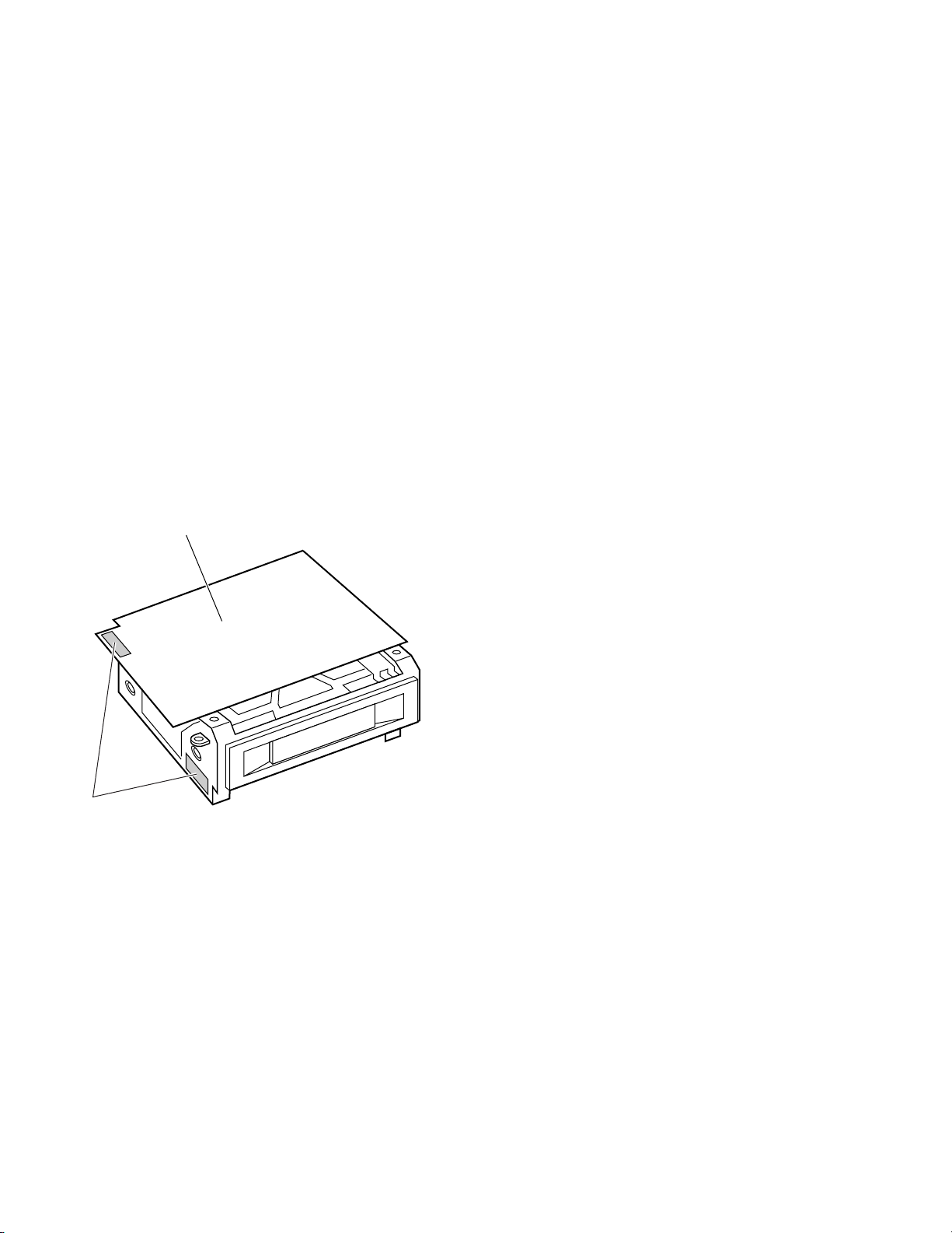
1.9 CAUTION FOR REPLACING THE DV MAIN BOARD
AND VIDEO SYSCON BOARD
When the DV MAIN board or VIDEO SYSCON board has been
replaced for servicing, be sure to enforce the following items.
1.9.1 DV MAIN Board
[A] About the ID Management Label
Each VCR unit carries an ID label in compliance with IEEE1394
showing the unique ID assigned on the production line.
(See the following figure for the label position.)
When replacing the DV MAIN board, remove the ID management label that was provided originally with the unit from the
defective board and attach it in the same position to the new
board.
DV MAIN board
[B] Load EEPROM Internal Data
The EEPROM provided with the new board for replacement
contains no data, while the EEPROM originally provided with
the VCR unit contains the IEEE1394 ID data as well as all adjustment data written in the assembly and adjustments written on
the production line. This means that the new VCR unit will not
function if the new EEPROM is used in the condition in which it
is delivered.
When replacing the DV MAIN board, load the internal data of
the EEPROM on the original board to the EEPROM of the new
board.
(1) How to use original EEPROM to new DV MAIN board.
Remove the EEPROM from the original DV MAIN board,
and attach the chip to the new board.
(2) How to write data from the original board to the new
EEPROM
How to load all parameters in EEPROM on original board to
new EEPROM by using the adjustment software.
(For details, see section 3.7.13)
(3) In case of original EEPROM on the original DV MAIN board
was broken.
Load the default data before making adjustments with the
adjustment software, write the data in the new EEPROM,
then make adjustments by following the adjustment procedures. (See section 3.7.12 for details.)
And then, input the ID number on the original board to new
EEPROM by using the adjustment software. (See section
3.7.13 for details.)
ID Label
Fig. 1-9-1
1.9.2 VIDEO SYSCON Board
[A] Transporting of IC407 (EEPROM) Data
When the SSF function is used, the cassette number recorded
on tape (see section 9.4.1) has the model ID code appended to
it. The model ID code is written in IC407 (EEPROM). However,
as the new EEPROM mounted on the new replacement circuit
board does not have the ID code written into it, the SSF function cannot work normally (the model ID code should be written
in IC407 for the correct operation of the SSF function).
Nevertheless, no means is provided for transporting the model
ID code from the original EEPROM to the new EEPROM. Therefore, it is recommended to remove the original IC from the original board and mount it on the new board.
[B] ID Management Label
An ID management label is attached to the camera head. For
the position, see Fig. 1-4-1.
1-12
Page 18

1.10 FUNCTIONS OF INTERNAL SWITCHES
1.10.1 DIP Switch S901 on ROM Board
Symbol ShipmentFunctionNameNo.
1 Adjustment mode Adjustment mode ON/OFF OFF
2 Check mode Check mode ON/OFF OFF
3 Not used OFF
S901
4 Character mixing TEST OUT character display ON/OFF OFF
5 Not used OFF
6 Color matrix adjustment Color matrix adjustment mode ON/OFF OFF
7 Setup (NTSC model only) ON (0% setup)/ OFF (7.5% setup) OFF
8 Function setting Initial setting of camera functions OFF
Table 1-10-1
(1) Adjustment mode (S901-1)
Set S901-1 to ON to initiate the camera electrical adjustment mode.
For details, see section 3.3.
(2) Check mode (S901-2)
Set S901-2 to ON to display the camera’s check mode screen
on the viewfinder.
In this mode, the auto white balance and auto iris control
data in the microcomputer controlling the camera can be
viewed and checked. (This mode is not used for adjustments
but is intended to simply allow the checking of control values and their functions.)
R-G
–
B-G
R GAIN LEVEL
B GAIN LEVEL
PEAK
APL
NAM ERROR
GAIN ∗dB
CHECK MODE
–
: ∗
: ∗
: ∗
: ∗
: ∗
: ∗
: ∗
: ∗
Fig. 1-10-1(1)
R-G/B-G
Shows the data on the R/G/B signals input to the CPU for
use in white balance control in terms of R-G and B-G. The
values are variable between -127 and 128.
These values approach 0 if the white balance circuit is activated by capturing a non-color image such as a gray scale.
R GAIN LEVEL/B GAIN LEVEL
Show the levels of the R and B channel white balance control signals.
These values are variable between 0 and 255.
The R value tends to decrease and the B value tends to
increase under low color temperatures (reddish lighting), and
the R value tends to increase and the B value tends to decrease under high color temperatures (bluish lighting).
PEAK
Shows the peak hold value of the video signal in a vertical
scanning period.
APL
Shows the average picture signal level.
NAM ERROR
Shows the NAM value used in the auto iris control.
The value is variable between -127 and 128.
The value approaches 0 when the auto iris control approaches
the optimum level.
GAIN
Shows the electrical gain value set with the GAIN switch on
the right-hand side of the unit.
Shows “ALC” in the full auto-shooting mode.
1-13
Page 19
(3) Character mixing (S901-4)
Set S901-4 to ON to superimpose the same characters as
those displayed on the viewfinder-screen in the output signal from the TEST OUT terminal. This is a convenient facility
for adjustment because the adjustment menu and screen
can be displayed on an external monitor.
(4) Color-matrix adjustment (S901-6)
Set S901-6 to ON to view the color-matrix adjustment-mode
screen on the
Viewfinder-screen.
This mode makes it possible to set color-matrix parameters
in details (see section 1.12).
* Note that the color-matrix adjustment is not a normal adjust-
ment item. It is usually not required to adjust the color-matrix because this has been set to the optimum level before
shipment.
* In case a color-matrix adjustment becomes necessary be-
cause of a user’s request, it should be performed in accordance with the description in section 1.2.
(5) Setup (S901-7): NTSC only
Set S901-7 to ON or OFF to select whether or not the output signal setup is included in the TEST OUT and MONITOR
OUT terminals output.
(Note that the signal recorded onto tape is not affected by
the position of this switch. The signal is always recorded
without the setup information.)
As changing the position of this switch does not alter the
signal level, it is not necessary to re-adjust the signal recording according to the position of this switch. This switch is
effective only on the camera video output. With the video
signal obtained by playing back a previously recorded tape,
whether the setup is included or not can be selected with
the item “SETUP” in the Service Menu (see section 1.13.3).
(6) Function setting (S901-8)
This switch is used to set the functions shown in Table 1-91(2).
This switch is usually used to switch the defaults of the domestic and export-oriented models.
S901-8
Function
GAIN
V. SCAN
ALC GAIN
L
M
H
OFF ON
0 dB
6 dB
9 dB
60.1 to 251.3
0 to + 18 dB
NTSC
60.1 to 2067.0
0 to + 18 dB
0 dB
9 dB
18 dB
PAL
Do not care
0 dB
9 dB
18 dB
50.1 to 2053.6
0 to + 18 dB
1.11 MODES REQUIRED IN SERVICING
1.11.1 Camera Service Menu
The CAMERA SERVICE MENU can be displayed on the viewfinder screen by setting the [POWER] switch to ON while tilting
the AUTO WHITE/ACCU FOCUS switch upward (toward AUTO
WHITE).
— — — CAMERA SERVICE MENU — — —
Cxxxx V
CCD CORRECT : ON
ERROR DETECT START
WHITE CLIP LEVEL : 108%
END
∗. ∗∗
<U>
Fig. 1-11-1
Select an item by turning the SHUTTER dial, and push the SHUTTER dial to select or set it.
Cxxxx V∗.∗∗<U>
This item displays the version number of the camer control software (IC902 on ROM board).
* The Character “U” after the Version No. indicates that U
version software is running. When “E” is shown here, the
software for E version is running.
CAUTION
Also be sure to reset the system after replacing IC902
(ROM) on the ROM board. See section 1.11.2, “System
Reset”.
CCD CORRECT (ON/OFF)
This item sets whether white blemish due to CCD is to be corrected or not.
To correct : ON
Do not correct : OFF
The factory shipment condition is ON. Even when OFF is selected with this menu, it is temporary and the correction status
(ON) is recalled automatically the next time the power is turned
on.
NOTE
• To correct any white blemish interference produced after
the factory shipment, perform the “ERROR DETECT
START” described on the next page. Be sure to warm up
the camera by leaving it on for more than 2 hours before
performing the “ERROR DETECT START”.
Table 1-9-1(2)
* The L/M/H positions of GAIN can also be set individually
using the [CAMERA MENU].
1-14
• The white blemish correction is performed with the lens
iris closed or with the lens cap on. In normal use, the lens
iris closes automatically when performing a white blemish
correction. However in a case when the lens cable is disconnected and the lens iris cannot be closed, “ERROR DETECT FAIL” will be displayed on the viewfinder and the
white blemish correction cannot be executed. Before performing the white blemish correction again, be sure to first
close the lens.
Page 20
ERROR DETECT START
When this item is selected and the SHUTTER dial is pushed,
the white blemish detection for correcting CCD white blemish
starts automatically.
The following messages are displayed on the viewfinder screen
during detection.
1.11.2 System Reset
While pushing the [SHUTTER] dial, press the [POWER] switch
to ON. This resets the system and initializes the menu set items
to their default values.
The following description shows items that are initialized to the
defaults by a system reset and those that are not.
ERROR DETECT EXECUTING
↓
ERROR DETECT END
After the completion of error detection, the camera is automatically set to the white blemish correction ON condition.
The following types of white blemish can be corrected.
(1) White blemish correction target area
5%
5%
Correction target area
90%
1.11.3 Resetting DSP Data
While pushing the [SHUTTER] dial and [STATUS] switch tilted
toward “SKIN AREA”, press the [POWER] switch to ON. This
resets the internal setting data (color matrix setting data) in the
DSP to the default setting.
1.11.4 Displaying Auto Iris Area Gate
While holding the [AUTO WHITE/ACCU FOCUS] switch down
(toward ACCU FOCUS), press the [POWER] switch to ON. The
area gate for the auto iris control is displayed in the viewfinder
screen.
90%
Fig. 1-11-2
(2) Details of correctable white blemishes
䡲 White blemishes at luminance levels of 30 mV or more
can be corrected. The total number of white blemishes
that can be corrected is up to 7 for the R, G and B signals.
䡲 Even when there are 2 white blemishes on a single scan-
ning line, both of them can be corrected. (However, when
they are adjacent, the results of a correction appear inferior to those of the results of the correction of a single
white blemish. These results are due to the correction characteristics themselves.)
WHITE CLIP
The white clip level of the through-camera composite output
signal that is output at TEST OUT can be selected from the following 2 values:
100% or 108% (shipment setting)
Fig. 1-11-3
1.11.5 List of Servicing Switches (Camera)
The following table that shows the switches described above is
for use in servicing. Use this table as a reference in servicing.
Switch Operation Result
[AUTO WHITE] + [POWER] ON Service menu display
[SHUTTER] + [POWER] ON System reset
[STATUS] + [SHUTTER] + [POWER] ON
[ACCU FOCUS] + [POWER] ON Area gate display
DSP data reset
Table 1-11-4
1-15
Page 21
1.11.6 EEPROM in Camera
IC905 on the CAM1 board is an electrically erasable/rewritable
EEPROM. It stores the following data.
䡲 Camera adjustment data set in the adjustment mode.
䡲 Settings in [CAMERA MENU].
䡲 White blemish position coordinate data for use in white blem-
ish correction.
䡲 Auto white balance control data (A/B).
䡲 Camera status at the last power OFF (positions of non-lock
type switches, etc.).
Therefore, when retention of the above data becomes impossible due to a failure in the EEPROM or over the 1 million times of
rewrite count, the EEPROM should be replaced with a new one
and the data should then be re-set in it.
1.11.7 Tripod base
See the KA-510U servide manual NO. 60065 for servicing.
The tripod is not exactly same as KA-510U. See note for the
difference.
Note
These 1/4 and 3/8 inch fixing tripod holes are not
povided for the KA-510U.
1.12 CHANGING THE COLOR MATRIX SETTING
NOTE
The color reproduction properties of the color-matrix circuit
built into the DSP can be re-set by varying the values of 9
parameters. However, as these parameters have been set at
the factory to the default values based on detailed studies of
the product development process, it is usually not recommended to alter them. Note that this adjustment is not a
normal electrical adjustment item.
Should a re-adjustment of the color matrix (a color reproducibility change) be required as a result of a user request, etc.,
this should be performed only after studying and understanding the details of the following instructions.
1.12.1 Setting the Color Matrix
Preparation
The color matrix setting requires a color chart for use as a
reference for color reproduction and a vectorscope. As we
do not specify a color chart for this purpose, discuss the
matter with any user requesting a custom setting and use a
color chart to be agreed by the user.
Adjustment
The color-matrix circuit can be set using menus displayed
on the screen (the viewfinder-screen or the test out screen).
Front
Front
Accessory
KA-510U
2–3/8"
Not provided
4–3/8"4–1/4"
2–1/4"
Not provided
Not provided
Rear
Rear
MODE : M3 M2 M1 DATA
R (R-G) :
R (R-B) :
G+(G-R) : X
G–(G-R) : X
G+(G-B) : X
G–(G-B) : X
B+(B-G) : X
B–(B-G) : X
B (B-R) :
Fig. 1-12-1
Use the following procedure.
(1) Remove the right side cover (see section 1.3.1)
(2) Set DIP switch S901-6 on the ROM board to ON to display
the color-matrix setting menu on both the viewfinder and
testout screens.
(3) Move the cursor (mark of “
”) to the desired item by using
the [SHUTTER] dial.
(4) When the cursor set on the desired item, pushing the [SHUT-
TER] dial causes the selected item to blink. (This is the status of the value adjustment.)
(5) When the adjustment value is blinking, rotating the [SHUT-
TER] dial varies the adjustment value. The available adjustment values are “M3”, “M2”, “M1” which is 0 or 1, and
“DATA” which is between 0 and 31.
1-16
Page 22
M3
0 : Active
1 : Inactive
M2
0 : Active
1 : Inactive
M1
0 : Increase
1 : Decrease
DATA
0 – 31
MODE
R±(R-G)
R±(R-B)
G+(G-R)
G–(G-R)
G+(G-B)
G–(G-B)
B+(B-G)
B–(B-G)
B±(B-R)
M3
M3
M2
M2
M2
M2
M3
M3
M3
M3
M3
M2
0 or 1
0 or 1
0 or 1
0 or 1
0 or 1
0 or 1
0 or 1
0 or 1
0 or 1
0 or 1
0 or 1
0 or 1
0 or 1
0 or 1
0 or 1
0 or 1
0 or 1
0 or 1
0 or 1
0 or 1
0 or 1
Active Area
Graph display
(6) Set DIP switch S901-6 on the ROM board to OFF. The color-
Inactive area:
Represents a vector area
that is not affected by a
currently selected setting
item.
M1 = 0: Increasing trend
M1 = 1: Decreasing trend
Color signal increase/decrease trend:
The increase or decrease trend can be
selected with M1.
Active area:
Represents the vector area that is affected
by a currently selected setting item.
(The area can be selected with M3 or M2
depending on the item.)
matrix setting menu is canceled and the normal screen appears again.
NOTE
The settings are stored and reflected every time a value in
an item is changed. The setting values marked “X” do not
need to be changed.
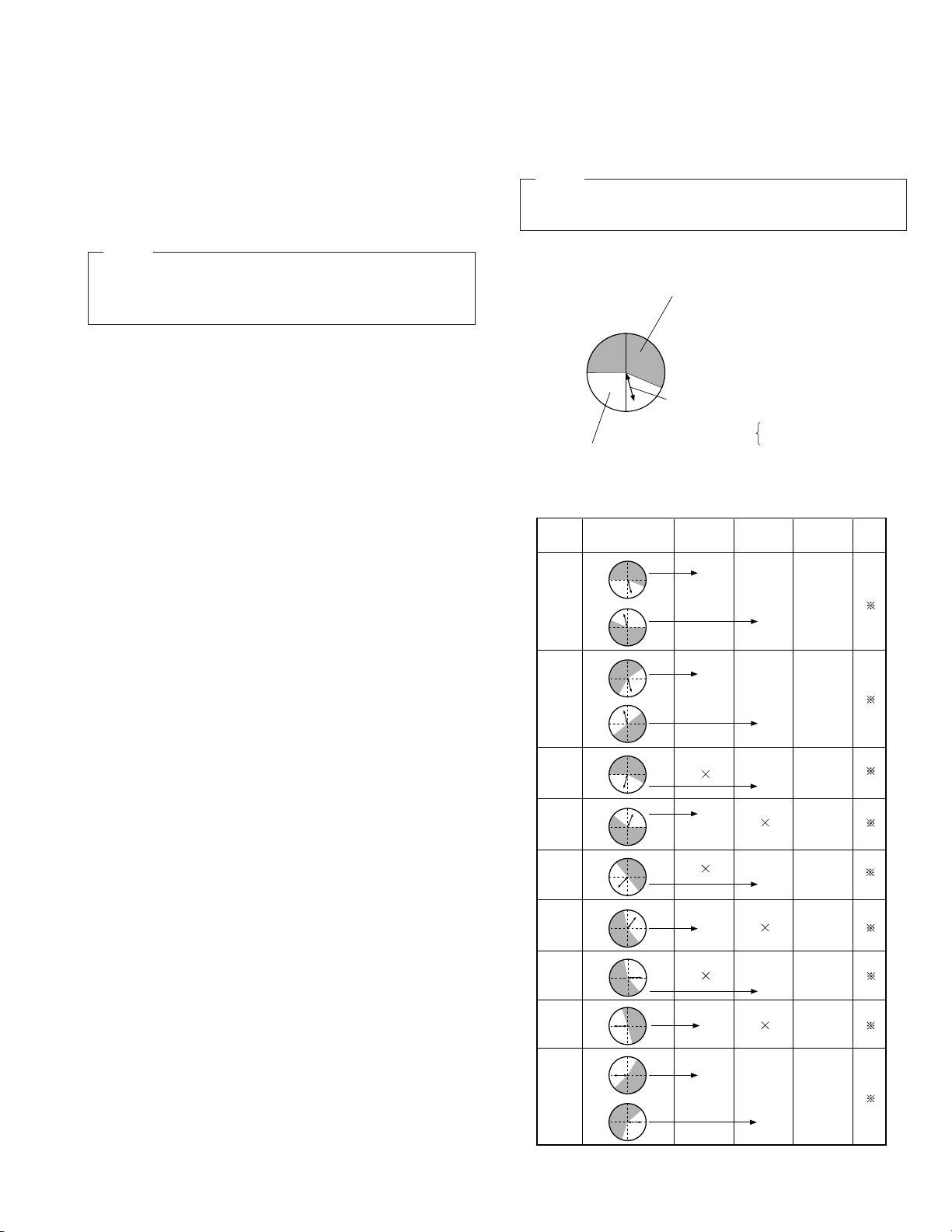
1.12.2 Details of Setting Items
As described above, the color matrix setting consists of varying
12 items using 9 parameters. The following table shows a comparison of the setting items.
NOTE
The model diagrams in the table may be interpreted as follows.
NOTE
If the [STATUS] switch is pressed during the value of some
adjustment item is blinking, all of the data being set is reset
to the default values.
(Example)
This diagram represents the display area of the vectorscope.
Table 1-12-1
1-17
Page 23

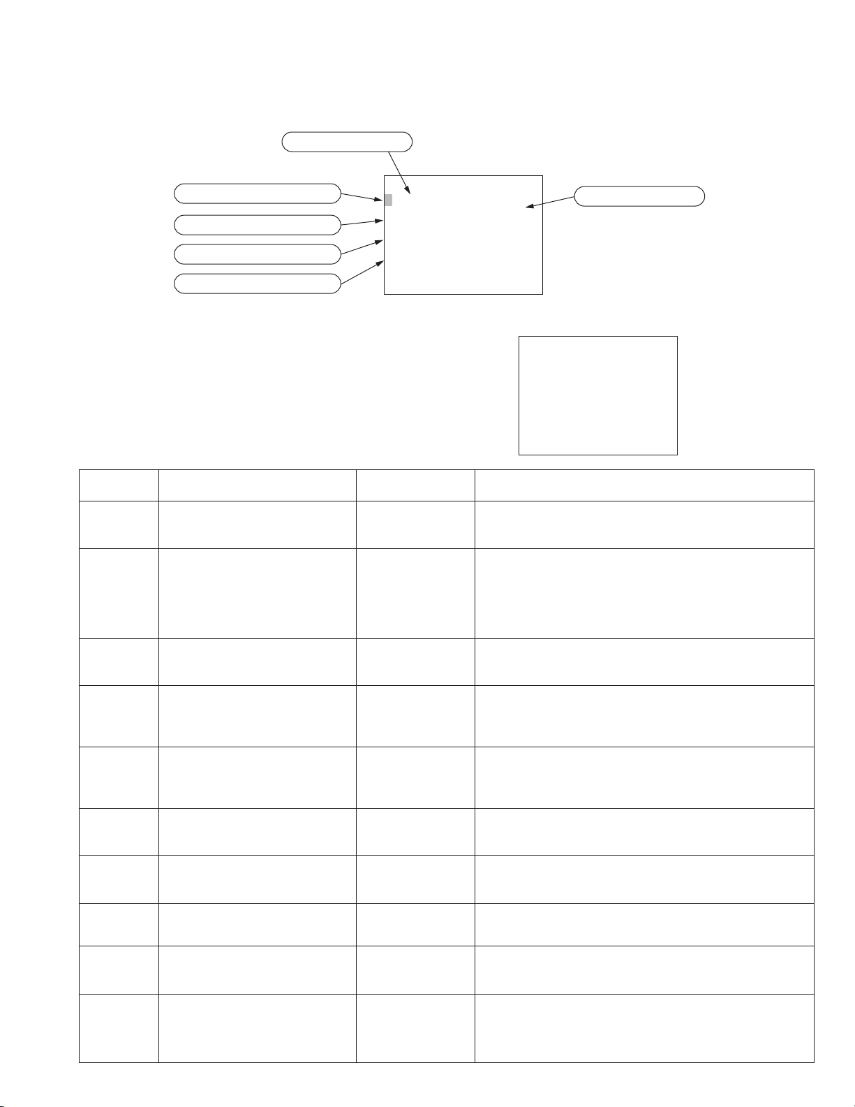
1.13 SERVICE MENU
1.13.1 Operation Method
When the [MENU] button is pressed, the setup menu appears on the viewfinder screen to allow the user to perform setups. (For the
contents of the setup menu, refer to page 66 of the instruction manual). Then, with the setup menu displayed, press the [MENU]
button while holding down the [LOG] button to display the service menu.
To change a menu setting value, press the [DATA SET] button. The viewfinder screen and counter display show the blinking “DATA
SET” indicators and the set returns to normal mode.
To return to the setup menu, turn the power off and then on again.
1.13.2 Configuration of the Service Menu (Displayed on the Viewfinder Screen)
GROUP
↓
→
:
SERVO/SYSTE
000
↓
100 :VIDEO
↓
20 0 : AUDI O
↓
300 :SYSTE
↓
↓
↓
↓
↓
↓
↓
→
↓
M
400 :TI
500 :ONSCREEN
700 :DI P S
HM: HOURMETER
RV :ROMVERSI ON
:
ERROR HI STORY
EH
OT:OTHERS
GROUP
M
E CODE
W
HOUR METER
SERECT
M
Initial display of the service menu.
Select an item with the [GROUP] button and press the [SELECT] button
to go to a lower hierarchical level.
ITEM
( HOURMETER)
↓
↓
↓
↓
↓
↓
↓
↓
M
DH : DRU
TH : TOTAL DR
PH : PO
CH : CAP HOUR
LD : LOADI NG T I
EJ : EJECT T I
HC : HEAD CREANI NG T I
FR : F
HOURMETER
M
W
ER HOURMETER
M
( HOURMETER)
M
ES
W
D/REV T IMES
HOURMETER
ETER
M
ES
000000H
000000H
000000H
000000H
000000
000000
M
ES
000000
000000
Hour meter data can be checked.
See section 1.13.4.
ROM VERSION
SERECT
ERROR HISTORY
SERECT
OTHERS
SERECT
(RO
M
VERSI ON)
SY : SYSCON RO
LT :LCD/TC RO
US : UNI T SY S RO
U
M
:UNITMSD ROMVER.
ITEM
ITEM
→
←
(ERROR HISTORY)
↓
1:ERR7101
CAP
M
↓
2:ERR7101
↓
3:ERR7101
↓
4:ERR7101
↓
MS:MEM
↓
ML:MEM
↓
M I:MEM
↓
EC : ERROR HI S TORY CL EAR
↓
LCD:LCD/KEY T EST
↓
DHC : DRU
↓
CHC: CAP H.M. C LEAR
↓
LTC:LOADING TIMES CLEAR
↓
ETC: EJECT T IMES CL EAR
↓
HTC :H . CLEAN TIMES CLEAR
FTC:F
OTOR FA I L URE
CAP
M
OTOR FA I L URE
CAP
M
OTOR FA I L URE
CAP
M
OTOR FA I L URE
(OTHERS)
ORY SWSAVE
ORY SWLOAD
ORY SWINITIALIZE
(OTHERS)
MH.M
(OTHERS)
W
D/REV T IMES C LEAR
M
VER.
M
VER.
M
VER.
.CLEAR
ROM version data can be checked.
See section 1.13.5 .
01
01
01
01
Error history of the 4 most recent errors can be
checked.
Pressing the [SELECT] switch in this screen
displays the mechanism information of each
error.
(MECHANI SMSWINFO.)
SELECT
(
M
ODE) REC
→
REC PAUSE
(EDCD) HLH
( HOUS ) O F F ( CASS ) ON
(SAFE ) OF F
(BGIN)OFF (END)ON
MENU
(RE
M
) OOHOOM
(P.T
M
) OOOOOOH
(TEMP) 60~
See sections 1.13.5 and 1.13.6.
The set-up menu contents can be saved, loaded or initialized
OFF
and the hour meter data can be reset.
OFF
See section 1.13.8.
After switching an item from OFF to ON using [SELECT],
OFF
execute the selected item by pressing [DATA SET]. It is not
OFF
possible to execute more than one item simultaneously.
OFF
When an item is switched ON, other items are switched OFF.
OFF
OFF
OFF
OFF
OFF
OFF
1-18
Page 24

1.13.3 Contents of Service Menu
Group Item Settings Counter Display
000
SERVO/
SYSTEM
002: OPERATION LOCK
050: REMOTE SELECT
ON
OFF
LOCAL
002 01
U
RSL Lc
IEEE1394
RS232C
080: BATTERY SHUTDOWN V
10.5 – 11.0V
BE 105
(0.1V step)
081: BATTERY ALARM V
082: BACK TALLY MODE
10.5 – 12.0 V
(0.1V step)
BLINK
BA 110
U
RT D BL
OFF
ON
083: FRONT TALLY MODE
BLINK
083 03
ON
100
VIDEO
125: SET UP
(Only U-ver.)
126: INPUT SELECT
OFF
ON
CAMERA
125 00
VD c
IEEE1394
200
AUDIO
244: LOW CUT
OFF
CH1
LcTF OF
CH2
245: SAMPLING RATE
CH1&CH2
32K
U
SPL 48
48K
246: FRONT VOLUME ENABLE
DISABLE
FRVL OF
ENABLE
300
SYSTEM
303: WARNING DISABLE
305: REC REPEAT
ENABLE
DISABLE
OFF
303 00
305 00
ON
306: LONG PAUSE DISABLE
ENABLE
306 00
DISABLE
307: LONG PAUSE TIME
3MIN
LGPT 03
30MIN
396: BATTERY TYPE
12V
BATT 12
13.2V
14.4V
398: SSF MODE
OFF
55F OF
CUE MODE
MARK MODE
400
TIME CODE
500
ON
SCREEN
406: USERS BIT GROUP
416: NON DROP/DROP
(Only U-ver.)
515: CALENDAR SELECT
516: DISPLAY SELECT
NOT SPECIFIED
ISO CHAR
UNASSIGNED1
UNASSIGNED2
DROP
NON DROP
JAPAN
USA
EUROPE
TC
40B 00
TcG DF
515 00
DSP Tc
CLOCK
00
23
OFF
ON
01
01
02
ON
32
01
01
01
30
13
14
cU
01
02
03
01
02
ON
01
NF
cL
U
R
Factory Default
OFF
LOCAL
10.5V
11.0V
BLINK
BLINK
ON
U
CAMERA
OFF
48K
ENABLE
ENABLE
OFF
ENABLE
30MIN
12V
CUE MODE
NOT
SPECIFIED
DROP
U-ver: USA
E-ver: EUROPE
TC
Description
Operation lock setting.
User setup menu (Refer to page 68 of
the instruction manual.)
Battery empty detection voltage setting.
Battery alarm detection voltage setting.
User setup menu (Refer to page 68 of
the instruction manual.)
Select the front tarry
BLINK: Blinking
ON: Lighting
Select the setup of MONITOR OUT in playback mode.
ON: Setup added.
OFF: No setup.
Input signal selection
User setup menu (Only U-ver.) (Refer to
page 68 of the instruction manual.)
User setup menu (Refer to page 68 of
the instruction manual.)
User setup menu (Refer to page 68 of
the instruction manual.)
User setup menu (Refer to page 68 of
the instruction manual.)
ENABLE: Warning enabled.
DISABLE: Warning disabled.
OFF: REC Full Repeat enabled.
ON: REC Full Repeat disabled.
ENABLE: Long pause is canceled after specified period of time (set using Menu 307).
DISABLE: Long pause is not canceled.
User setup menu (Refer to page 68 of
the instruction manual.)
User setup menu (Refer to page 68 of
the instruction manual.)
User setup menu (Refer to page 68 of
the instruction manual.)
User bit’s binary group flag setting
User setup menu (Refer to page 68 of
the instruction manual.)
Calendar display format selection.
JAPAN: Year/Month/Day
USA: Month/Day/Year
EUROPE: Day/Month/Year
User setup menu (Refer to page 68 of
the instruction manual.)
1-19
Page 25

Group Item Settings Counter Display
Factory Default
Description
700
DIP SW
Operations are not accepted when the cassette cover is open. Therefore, DIP switch-0 and -1 can be used in checking the operation when the
side cover is open or in the compatibility adjustment.
700: DIP SWITCH-0
701: DIP SWITCH-1
702: DIP SWITCH-2
to to
715: DIP SWITCH-15
OFF
ON
OFF
ON
OFF
ON
700 00
701 00
702 00
715 00
01
01
01
01
OFF
OFF
All OFF
Operate LED display switching
OFF: Blinks in amber when the cassette
cover is opened.
ON: Extinguished when the cassette
cover is opened.
OFF: Other operations than ejection are
inhibited when the cassette cover is
opened.
ON: Operations are valid even when the
cassette cover is opened.
Switching inhibited. Must be set to OFF.
1.13.4 HOUR METER
This screen allows the data of hour meters to be checked.
Item
DRUM HOUR METER
TOTAL DRM HOUR METER
Counter Display
DH∗∗∗∗∗∗
TH∗∗∗∗∗∗
Description
Displays the drum rotation hours.
Displays the total drum rotation hours. This data can-
Max. Display Hours/Count
999999H
999999H
not be reset.
POWER HOUR METER
PH∗∗∗∗∗∗
Displays the power ON hours. This data cannot be re-
999999H
set.
CAP HOUR METER
LOADING TIMES
EJECT TIMES
HEAD CLEANING TIMES
FWD/REV TIMES
cH∗∗∗∗∗∗
LH∗∗∗∗∗∗
EJ∗∗∗∗∗∗
Hc∗∗∗∗∗∗
FR∗∗∗∗∗∗
Displays the capstan motor rotation hours.
Displays the loading count.
Display the ejection count.
Displays the active cleaning head operation count.
Displays the forward or reverse operation count
999999H
999999TIMES
999999TIMES
999999TIMES
999999TIMES
∗∗∗∗∗∗ are the figures of time (or count).
1.13.5 ROM VERSION
This screen allows the ROM versions to be checked.
Item
SYSCON ROM VER. Video/Sys-con board IC403 PLSL1063-V1-**
LCD/TC ROM VER. Audio/LCD board IC601 UPD78P058BT***
UNIT SYS ROM VER. DV MAIN board IC101 MN102F1617HL-**
UNIT MSD ROM VER. DV MAIN board IC401 M31020EAVP-***
Counter Display
SY ∗∗
LT ∗∗
US ∗∗
U
U ∗∗
Board Name Symbol No. Remark
ROM board IC1 M27W102-80N6-**
(The MSD CPU program is written in
IC401 and ROM board IC1.)
(The ROM version No. of PAL begins
with “80”.)
∗∗ is the version number.
1-20
Page 26
1.13.6 ERROR HISTORY
This screen allows the history of the 4 most recent errors to be checked.
Error code
( ER ROR H I ST ORY )
Latest warning
Warning before the latest
Warning before the above
1: ERR7101
CAP
2: ERR7101
CAP
3: ERR7101
CAP
4: ERR7101
CAP
M
OTOR FA I L URE
M
OTOR FA I L URE
M
OTOR FA I L URE
M
OTOR FA I L URE
Warning before the above
1.13.7 MECHANISM SW INFO
This screen allows the mechanism mode at each error to be displayed.
Error message
(MECHANISMSWINFO. )
(MODE ) R E C
→
(EDCD) HLH
( HOUS ) O F F ( CA SS ) ON
( SAFE) OF F
(BGIN)OFF (END)ON
(RE
(P.T
(TEMP) HIGH
REC PAUSE
M
) OOHOOM
M
) OOOOOOH
Display
Item
(MODE)
(ECOD)
(HOUS)
(CASS)
(SAFE)
(BGIN)
(END)
Description
Mode at the moment of VCR error & mode immediately before.
Rotary encoder output.
Cassette housing switch status.
Cassette switch status.
REC safety switch status.
Tape begin sensor status.
Tape end sensor status.
Input Pin
—
DV MAIN board
IC401
Pin 44 → CAM0
Pin 45 → CAM1
Pin 46 → CAM2
DV MAIN board
IC401 pin 27
DV MAIN board
IC401 pin 32
DV MAIN board
IC401 pin 47
DV MAIN board
IC401 pin 126
DV MAIN board
IC401 pin 125
Display
PLAY, STILL, REC, REC PAUSE, NO CASSETTE, EJECT,
STNDBY-ON, FF, REW, SHTL, STILL, SHTL X10, SHTL X-10
Shows H or L according to the mechanism position.
Rotary encoder terminal
(ENCD) H L H
CAM0 CAM1 CAM2
ON : Housing inserted/ejected status
OFF : Housing operating status
ON : Cassette tape inserted
OFF : Cassette tape not inserted or during insertion /ejec-
tion
ON : Non-recordable tape inserted, cassette tape not in-
serted or during insertion /ejection
OFF : Recordable tape inserted
ON : Tape leader section detected
OFF : Magnetic tape section detected
ON : Tape leader section detected
OFF : Magnetic tape section detected
(REM)
(P.TM)
(TEMP)
Remaining tape at the moment of
error.
POWER HOUR METER data at
the moment of error.
Set’s internal temperature at the
moment of error
—
—
DV MAIN board
IC101 pin 75
Remaining tape time
POWER HOUR METER time
UNDER : under 10°C
NORMAL : 10 to 40°C
HIGH : 40 to 60°C
OVER : over 60°C
1-21
Page 27
1.13.8 OTHERS
This screen allows the setup menu to be saved temporarily, loaded or initialized.
To execute an item, switch it from “OFF” (displayed as “00”) to “ON” (displayed as “01”) with the [SELECT] button, then press the
[DATA SET] button (excluding hour meter). As switching an item “ON” switches other items automatically “OFF”, it is not possible to
execute more than one item simultaneously.
Item
MEMORY SW SAVE
MEMORY SW LOAD
MEMORY SW INITIALIZE
ERROR HISTORY CLEAR
LCD/KEY TEST
DRUM H.M. CLEAR
CAP H.M. CLEAR
LOADING TIMES CLEAR
EJECT TIMES CLEAR
H. CLEAN TIMES CLEAR
FWD/REV TIMES CLEAR
Counter Display
U
S00
U
L00
U
Ec 00
LcD 00
DHc 00
cHc 00
L7c 00
E7c 00
H7c 00
F7c 00
1.14 ALARM DETECTION METHODS
Factory Default
00
OFF
OFF
OFF
OFF
OFF
OFF
OFF
OFF
OFF
OFF
OFF
Description
Saves the data set with the setup menu.
Loads the data set for the setup menu.
Initializes the setup menu data to the factory defaults.
Clears the error history.
Checks the lighting of operation key LEDs.
After changing the setting to “START”, press the [DATA SET] but-
ton. The viewfinder screen and LCD display show “PERFORM”
and the key test mode is set. In this mode pressing an operation
key, lights the corresponding LED but does not cause the VCR to
operate. To exit from the key test mode, change the setting to
“STOP” and press the [DATA SET] button. The viewfinder screen
and LCD shows “PERFORM” and the normal mode is reset.
Resets the drum hour meter.
Resets the capstan hour meter.
Resets the loading count.
Resets the ejection count.
Resets the head cleaning count.
Resets the forward/reverse operation count
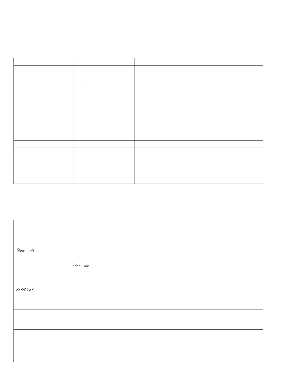
The unit incorporates the alarm display function, which notifies the user of the VCR status, remaining tape and remaining battery
power. For the contents of the alarm display, see page 86 of the instruction manual. This section describes the methods applied for
alarm detection.
Item
Servo lock error
“SERVO”
(Counter display)
Head clog
“RF”
(Counter display)
Dew condensation
When the drum rotation phase is deviated by more than
10 or when the capstan motor rotation speed is deviated by more than 20%.The alarm sound is generated
in REC mode. The alarm display only appears in the
PLAY mode.
When external sync input signal SYNC IN is disturbed,
“
” (sync inhbit) is displayed.
Measures the error rate during playback or quick review with RET button and displays “HEAD CLOG”
when the viterbi is ON and exceeds 2000 (total).
When dew warning occurs with the VCR.
Description
Status After Detection
Same mode is
maintained.
Detection Method
The MSD microcomputer
detects the drum rotation
phase from the phase error
between the TSR and HID
signals. The capstan motor
rotation speed is detected
based on the CAP FG signal.
Same mode is
maintained.
—
See error code “0201 DEW” in 1.16.
“DEW”
Lithium battery exhaustion
“Li”
When the built-in lithium battery for the timecode
backup is exhausted or not installed.
Same mode is
maintained.
Decrease in the
battery voltage
below 2.6 V.
Remaining battery
When the remaining battery power is low.
• Battery nearly empty:
Operation is maintained.
Detects the voltage
at system controller
pin 62.
• Battery empty: Operation stops automatically.
1-22
Page 28
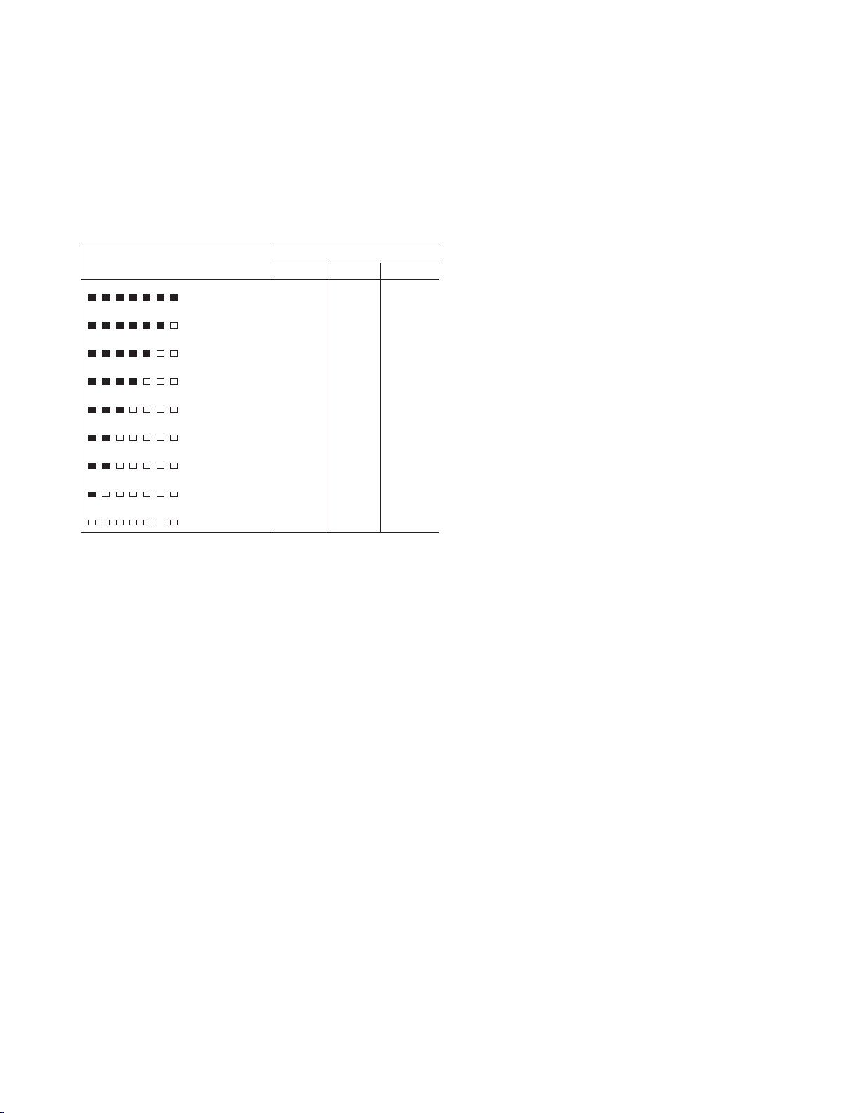
1.15 BATTERY POWER DETECTION METHODS
1.16 WARNING CODES
The battery voltage is detected to display the remaining power
on the LCD. Since the detection voltage is variable depending
on the 12 V/13.2 V/14.4 V battery types, correct settings should
be made with the setup menu.
Detection voltage and remaining battery display
12V
Battery Type
13.2V
3.9V –
13.2V – 13.8V
13.0V – 13.1V
12.8V – 12.9V
12.4V – 12.7V
12.3V
11.6V – 12.2V
10.6V – 11.5V
– 10.5V
14.4V
15.1V –
14.4V – 15.0V
14.2V – 14.3V
13.9V – 14.1V
13.6V – 13.8V
13.4V – 13.5V
12.6V – 13.3V
10.6V – 12.5V
– 10.5V
EFBATT
EFBATT
EFBATT
EFBATT
EFBATT
EFBATT
EFBATT
EFBATT
EFBATT
Display
(“F” off)
(“F” off)
(“F” off)
(“F” off)
(“F” off)
(“F” off, “BATT” blinking)
(Segment blinking)
(“F” off, “BATT” blinking)
(Segment blinking)
(“F” off, “BATT” blinking)
(Segments off)
12.6V –
12.0V – 12.5V
11.8V – 11.9V
11.6V – 11.7V
11.3V – 11.5V
11.2V
11.0V – 11.1V
10.6V – 10.9V
– 10.5V
If a problem occurs during operation, the unit diagnoses the
cause by itself, provides a warning through the “warning LED”
and “buzzer”, and displays the diagnosis results in the counter
display.
[LCD counter]
Error display appears. (∗∗∗∗ is the error code.)
ERR-∗∗∗∗
[Warning LED]
The red LED blinks (at about 4 Hz).
[Buzzer]
Generates a continuous tone. However, the tone is intermittent
(at about 4 Hz) in case of dew alarm.
0201 Condensation
•VCR operation
In save mode:
· If a cassette is loaded, enters the AUTO OFF mode.
· If a cassette is not loaded, the warning LED lights
and the SAVE mode is maintained.
In other modes:
· If a cassette is loaded, the AUTO OFF mode is ini-
tiated.
· If a cassette is not loaded, the warning LED lights
and the drum rotates. An operation is accepted after any condensation has evaporated.
•Cause : Condensation of moisture.
•Detection method : Check the voltage at the pin 124 of
IC401.
DEW ON : 2.4 V or more
DEW OFF : 1.8 V or less
0601 WRONG CASSETTE TYPE
•VCR operation : The AUTO OFF mode is initiated.
•Cause : A wrong type of cassette for the
computer is inserted.
•Detection method : An error in the cassette type is detected (at pins 117, 118 and 119 of
IC401) after the insertion is completed.
3200 LOADING INCOMPLETE
•VCR operation : The AUTO OFF mode is initiated.
•Cause : Malfunction of the loading motor,
rotary encoder or mechanism.
•Detection method : The rotary encoder output is
checked (at pins 44, 45 and 46 of
IC401) and an error is detected
when loading has not completed in
4 seconds.
1-23
Page 29

3300 UNLOADING INCOMPLETE
•VCR operation : After the first unloading error, the
cassette is loaded temporarily, then
unloading is retried. If the retry fails
again, the AUTO OFF mode is initiated.
•Cause : Malfunction of the loading motor,
rotary encoder or mechanism.
•Detection method : The rotary encoder output is
checked (at pins 44, 45 and 46 of
IC401) and an error is detected
when unloading has not completed
in 4 seconds.
4000 INTAKE INCOMPLETE
•VCR operation : The AUTO OFF mode is initiated.
•Cause : Malfunction of the cassette hous-
ing switch or cassette housing motor.
•Detection method : When completion of insertion is not
detected (at pin 27 of IC401) within
3 seconds after the start.
5607 TU/SUP REEL STOPPED DUE TO A CUT TAPE
•VCR operation : The AUTO OFF mode is initiated.
•Cause : Tape is cut due to abnormal tension
or a mechanism defect or because
the cassette was inserted while the
tape was slack.
•Detection method : When the FGs from the SUP and
TU reels were not detected at all (at
pins 59 and 60 of IC401) during loading.
5702 TAPE END DETECTED AFTER SHORT REW
•VCR operation : The AUTO OFF mode is initiated.
•Cause : Tape is cut after the end of the tape
has been detected. The mode transition of the mechanism failed.
•Detection method : When the tape end sensor output
(at pin 125 of IC401) remains Low
even after 3 seconds have elapsed
since the start of the short REW
operation following the tape end
detection in play mode, etc.
4100 EJECTION INCOMPLETE
•VCR operation : The AUTO OFF mode is initiated.
•Cause : Malfunction of the cassette hous-
ing switch or cassette housing motor.
•Detection method : When completion of ejection is not
detected (at pin 27 of IC401) within
3 seconds after the start.
5605 TAPE BEGIN/END DETECTED SIMULTANEOUSLY
•VCR operation : The AUTO OFF mode is initiated.
•Cause : Tape is cut due to abnormal tension
or a mechanism defect or because
the cassette was inserted while the
tape was slack.
•Detection method : When both the tape begin sensor
(at pin 126 of IC401) and the tape
end sensor (at pin 125 of IC401)
output Low level together when a
cassette is loaded.
5606 SP REEL RUNAWAY DURING UNLOADING
•VCR operation : The AUTO OFF mode is initiated.
•Cause : Tape is cut due to abnormal tension
or a mechanism defect or because
the cassette was inserted while the
tape was slack.
•Detection method : When the detected TU reel rotation
count (at pin 59 of IC401) exceeds
30 revs. per sec. (1200 pulses) during unloading.
5802 TAPE BEGIN DETECTED AFTER SHORT FF
•VCR operation : The AUTO OFF mode is initiated.
•Cause : Tape is cut after the end of the tape
has been detected. The mode transition of the mechanism failed.
•Detection method : When the tape begin sensor output
(at pin 126 of IC401) remains Low
even after 3 seconds have elapsed
since the start of the short FF operation following the tape beginning
detection in the reverse search
mode, etc.
7001 DRUM MOTOR ROTATION ERROR
•VCR operation : The AUTO OFF mode is initiated.
•Cause : Malfunction of the drum motor,
MDA circuit or FG detector circuit.
•Detection method : When the drum FG has not been
detected (at pin 54 of IC401) for
more than 4 seconds in the drum
driving mode.
7101 CAPSTAN MOTOR ROTATION ERROR
•VCR operation : The AUTO OFF mode is initiated.
•Cause : Malfunction of the capstan motor,
MDA circuit or FG detector circuit.
•Detection method : When the drum FG has not been
detected (at pin 55 of IC401) for
more than 2 seconds in the capstan
driving mode.
1-24
Page 30

7202 SUP TAPE SLACK DURING CAPSTAN DRIVE
•VCR operation : The AUTO OFF mode is initiated.
•Cause : The timing belt is cut or one of the
reel control parts in the mechanism
is malfunctioning.
•Detection method : When the SUP reel FG has not been
detected (at pin 60 of IC401) during
5 rotations of the capstan in the capstan driving mode.
7302 TU TAPE SLACK DURING CAPSTAN DRIVE
•VCR operation : The AUTO OFF mode is initiated.
•Cause : The timing belt is cut or one of the
reel control parts in the mechanism
is malfunctioning.
•Detection method : When the TU reel FG has not been
detected (at pin 59 of IC401) during
5 rotations of the capstan in the capstan driving mode.
7305 NO TU REEL ROTATION DURING UNLOADING
•VCR operation : The AUTO OFF mode is initiated.
•Cause : Malfunction of the cassette hous-
ing switch or cassette housing motor.
•Detection method : When the TU reel rotation detected
(at pin 59 of IC401) during unloading is less than 1/2 turn.
1-25
Page 31

1.17 ANALYSIS OF BLOCK NOISE (SYMPTOMS: POOR VIDEO, ABSCNCE OF AUDIO)
1.17.1 Analysis Flow Chart
In case of trouble, perform troubleshooting using the following flow chart.
Start
Play cleaning tape.
NG
Play the recorded
tape to measure error rate.
Is the error rate less than 500
(one channel) and less than 1000(total)
when the viterbi is on?
NG
Check RF envelope.
•Is waveform flat?
•Are SUP and TU pulses
continuous?
OK
OK
OK
NG
Dirt deposited on the head.
Played tape defect.
The dirt deposited on the drum.
↓
Clean the drum.
2.12.5 Compatibility Adjustment.
Play cleaning tape.
Play the recorded
tape to measure error rate.
Is the error rate less than 500
(one channel) and less than 1000 (total)
when the viterbi is on?
Ye s
Play moving image.
Is monitored video OK?
Ye s
End
NG
NG
Drum or PB CD defect.
Digital processing circuitry
(DV Main) defect.
1-26
Page 32

1.17.2 RF Envelope Check
Symptom Observed
on Monitor Screen
Block noise on left SUP dropout • No audio output.
Block noise on right TU dropout • Timecode not counted.
One CH frozen No video output from one CH • Audio is output.
RF envelope Audio, etc. Possible Causes
• Intermittent audio.
• Supply guide roller adjustment
failure.
• Dirt on supply side of drum.
• Take-up guide roller
adjustment failure.
• Dirt on take-up side of drum.
• Dirt attached on one CH of
head.
• Drum assembly defective.
• PR & MDA board IC901
defective.
Frozen Low level
• No audio output.
• Dirt attached on head.
• Drum assembly defective.
The RF envelope condition can be confirmed to a certain degree in the Error Rate adjustment display.
RF envelope condition
1-27
Page 33

2.1 BERORE ADJUSTMENTS
SECTION 2
MECHANICAL ADJUSTMENTS
2.1.1 Precautions
1) Be sure to apply a screw securing torque when attaching a
part.
The securing torque should be 0.04 N-m (0.4 kgf-cm) unless
otherwise specified.
2) Always unplug the power cord of the set before attaching,
removing or soldering a part.
3) When unplugging a connector, do not pull the wire but grasp
the connector body.
4) Do not make an adjustment or rotate a potentiometer blindly
while the source of trouble is not identified.
5) Before adjusting electrical circuitry, be sure to wait for more
than 10 minutes after turning the power on.
2.1.3 Equioment required for adjustments
DV 12 V power supply(AA-G10/AA-P250)
1
Output capability
of 3 A or more.
Alignment tape
2
MC-1 (NTSC)
MC-2 (PAL)
2.1.2 Measuring instruments required for adjustments
Instrument
Oscilloscope
Calibrated instrument with measuring
Condition
bandwidth of 100 MHz or more.
Personal computer
Microsoft Windows 95 environment,
Pentium 133 MHz or better,
Memory 16 MB or more.
Table 2-1-1
Slit washer attaching tool
7
YTU94121A
Connector cable
8
PTU94018A
3
DV tape
For use
in self-recording/playback. (60 ME)
Cassette torque meter
4 10
YTU94150A
Guide screwdriver
5
YTU94085
Torque screwdriver
6
YTU94088 YTU94088-003
Replaceable bit
(long type)
9
PC cable
QAM0099-001
Adjustment software
PLSC1304
Chip IC replacement tool
11
PTS40844-2
2-1
2-2
Table 2-1-2
Page 34

2.2
BASICS OF MECHANISM DISASSAMBLY/ASSEMBLY
2.2.1 Assembly mode
The disassembly and assembly of the mechanism can be done
in the ASSEMBLY mode (see Table 2-2-1).
The ASSEMBLY mode is provided in the intermediate position
between C-IN and S.FF. As the C-IN (Cassette IN) mode is usually set when a cassette tape is ejected, the ASSEMBLY mode
should be entered after entering the C-IN mode. To set the AS-
SEMBLY mode, apply 3 V DC to the electrodes at the top of the
loading motor shown in Fig. 2-2-1. The ASSEMBLY mode is set
when the markings (red) on two gear teeth of the rotary encoder are aligned with the confirmation holes.
MODE
PARTS
1
ROTARY
ENCORDER
R. ENC -20
MAIN CAM GEAR 0
2
3
The ASSEMBLY mode is set
Note:
36°
according to the markings
(colored red) on two gear teeth
of the rotary encoder.
C-IN
ASSEMBLY
17°
0
15
Wire (Brown)
S. FF
30.33°
33.33
40
36.33°
87°
Table 2-2-1
Motor bracket assembly (Loading motor)
LOADING END
169.66°
166.66
140
PLAY REV STOP FF/REW
270.33°
276.33°
223.66°
226.66
185
229.66°
303.66°
273.33
220
306.66
245
190.33°
193.33
160
196.33°
Marking
Wire (Red)
(colored red)
Rotary encoder
< ASSEMBLY MODE >
C
H
Back side of Mechanism assembly
Fig. 2-2-1
2-2
2-3
Page 35

2.2.2 Mechanism modes
The mechanism has 6 modes as shown in Table 2-3-1.
The current mode can be confirmed by observing the markings
on the sub-cam gear and the 8 mark on the main deck at the
back side of mechanism assembly. See Figs. 2-2-2 to -7.
1. Mechanism mode confimation
<C-IN : C >
C H P
H
<S-FF : H > <PLAY : P >
Fig. 2-2-2 Fig. 2-2-3 Fig. 2-2-4
<REV : R > <STOP : S > <FF/REW : F >
R S F
Fig. 2-2-5 Fig. 2-2-6 Fig. 2-2-7
2-3
2-4
Page 36

2.3 MECHANISM TIMIN CHART
See following table (Table 2-3-1).
MODE
PARTS
36°
1
ROTARY
ENCORDER
2
3
ROTARY ENCODER
MAIN CAM GEAR 0
SUB CAM GEAR
POLE BASE
CTL PLATE
FF/REW
MAIN BRAKET(SUP)
MAIN BRAKET(TU)
SUB BRAKE
ON(REV MODE PRESS UP)
ON(PLAY MODE)
PINCH ROLLER
EXIT GUIDE ARM
HALF LOADING
TENSHION ARM
BAND ARM PLATE
CLUTCH LOCK
SUP CENTRRING
OFF
S/REV
PLAY
ON 1
ON 2
OFF
ON 1
ON 2
OFF
OFF
OFF
ASSY
OFF
OFF 1
OFF 2
OFF
OFF 1
OFF 2
ASSEMBLY
C-IN
17°
-20
0
15
0
ON
ON
ON
ON
ON
S. FF
30.33°
33.33
40
4015
36.33°
87°
LOADING END
169.66°
166.66
140
140
PLAY REV STOP FF/REW
270.33°
276.33°
223.66°
226.66
185
185
229.66°
303.66°
273.33
220
220
306.66
245
245
190.33°
193.33
160
160
196.33°
CENTERRING. ARM
S/REV
Table 2-3-1
2-4
2-5
Page 37

2.4 MAINTENANCE AND INSPECTION OF MAJOR PARTS
Periodical inspection and maintenance are requisite to maintain
the initial performance and reliability of the product. Table 2-4-1
(Maintenance & Inspection List) has been compiled assuming
standard operating conditions, and the specifications in the table are greatly variable depending on the actual operating environment and conditions. Remember that, if the maintenance
and inspection are not enforced properly, the operating hours of
2.4.1 Layout of Major Parts
To attach the Active Head Cleaner Assembly, refer to "1.7.2.
Disassembling the Rear Part of the Unit".
Cleaner bracket ass'y
the product will not only reduce considerably but other
unfavorable influences may produce.
Rubber parts may deform or degrade after long period of storage even if they are not used in this period.
The service life of the drum is variable depending on the tape
used and operating environment.
Active head cleaner
assembly
43
21
11
22
8
34
35
14
37
7
29
30
2 19 42 1 18 41 3
9
23
25
5
15
10
38
39
31
6
40
46
2-5
2-6
17 12 36 20 444 32
45
26
~
33 24 1328
Page 38

2.4.2 Maintenance and insoection list
1) The 6000 H maintenance consists of a replacement of the entire mechanism assembly.
2) When mounting the capstan motor on the main deck, control of the verticality is required. Therefore, when the capstan motor
reaches the end of its service life, the entire mechanism assembly should be replaced.
Part Name Ref.
Tape transport parts
1
2
ENT. guide base assembly
⁄
3
Tension arm sub-assembly
8
4
Guide rail (S) assembly
(
5
Guide rail (T) assembly
%
6
Middle catcher assembly
3
7
Capstan shaft
7
8
Pin roller arm assembly
5
9
Exit guide arm assembly
9
10
11
12
13
14
15
16
17
18
19
20
21
22
23
24
25
26
27
28
29
30
31
32
Drum assembly
1
Capstan motor
q
Reel drive pulley assembly
fi
Center gear assembly
›
Timing belt
‹
Clutch lock gear (1)
°
Clutch lock gear (2)
‡
Sub-brake assembly
6
Main brake (S) assembly
@
Main brake (T) assembly
#
15Reel disk assemblies
$
Band arm plate assembly
7
Swing arm assembly
0
Worm wheel 2
¤
Motor bracket assembly
2
Rotary encoder assembly
¢
Centering arm assembly
¶
Min cam
∞
Sub cam
•
Cleaner assembly
e
Cassette guide pin
r
Cassette guide
t
MIC contact
y
Mechanism assembly (including cassette housing assembly)
Symbol
No.
M643
M640
M622
M623
M624
M6 4
M644
M643
M650
M6 4
M633
M634
M611
M612
M614
M636
M638
M637
M639
M641
M642
M6 3
M620
M621
M626
M6 8
M6 9
M529
M635
M635
M635
M6 1
500
1000
>
>
>
Operating Hours (DRUM Hour Meter)
1500
2000
>
>
>
>
2500
3000
>
>
>
3500
4000
>
>
>
>
4500
5000
>
>
>
5500
6000
2.7.14
2.7.8
2.7.12
2.7.12
2.7.5
2.7.3
2.7.4
2.7.2
2.7.15
2.7.14
2.7.14
2.7.15
2.7.10
2.7.10
2.7.10
2.7.11
2.7.8
2.7.7
2.7.14
2.7.2
2.7.18
2.7.18
2.7.18
2.7.19
2.7.20
: Clean with ethanol. : Check and replace if required. : Replace. >: Oil the shaft.
After replacing a part, apply lubricant to the required points.
Table 2-4-1
2-6
2-7
Page 39

2.4.3 Cleaning
The tape transport system should be cleaned periodically. Be
sure to clean the tape transport system upon receipt of a set for
servicing, etc. To clean use a good quality fine-textured cloth
moistened with ethyl alcohol.
1) When the video head is stained, the playback output decreases and a read error will not be able to be corrected by
the error correction. If this occurs, the video will be interfered by block noise, the audio will not be output, and the
video output will eventually be lost when the video head
becomes extremely dirty. To clean the drum, while applying
cleaning cloth (service part No. : KSMM-01) or high quality
paper gently to the upper drum, rotate the upper drum in
the normal (counterclockwise) rotation direction.
The dirt deposited on the video head can be removed by
playing a cleaning tape.
CAUTION
Do not move the cleaning paper while applying it to
the video head. Otherwise, the video head may be
damaged.
2) The lower drum tends to attract dirt on the leader section
and the linearity cannot be guaranteed when the lower drum
becomes extremely dirty. Particularly, the tape inlet and output sections gather dirt easily, causing symptoms such as
dropout of the reproduced FM signal, deterioration of video
quality and lack of audio output. In order to clean the leader
section, rub a a cotton swab gently along its edge.
2.4.4 Oiling and Greasing
Table 2-4-2 shows the oil and greases used with the set.
Classification
Oil
Grease
1) Oiling should be performed periodically. Oil the shafts by
referring to the maintenance table.
2) After replacing a part, grease the required points. For the
parts to be greased see the exploded diagram in chapter 5,
“DISASSEMBLY DRAWINGS AND PARTS LIST”.
3) As Hanal separates over time, be sure to mix it (shake) well
before use.
4) Take care not to leave grease or oil on the tape transport
parts which come into contact with the tape or on the brake
pads.
5) Take care not to apply too much oil or grease. The standard
oiling quantity is one drop and the standard greasing quantity is the quantity with which the grease does not overflow.
Name
Cosmo Hydro HV100
Maltemp SH-P
Hanal
Table 2-4-2
Part No.
YTU94027
KYODO-SH-P
RX-410R
3) Stain of the tape transport system leads to tape damage.
When magnetic powder or dirt penetrates inside the rollers,
a rotation malfunction may affect the video. Clean the tape
transport parts carefully using a cleaning cloth or cotton swab
moistened with ethyl alcohol.
2-7
2-8
Page 40

2.5 PERIODICAL MAINTENANCE
Perform maintenance at the correct times in accordance with the maintenance table.
Fig. 2-5-1 shows the flow chart of periodical maintenance procedures at different operating hours.
6000-hour maintenance2000-hour maintenance1000-hour maintenance
StartStartStart
Replaced parts
Center gear assembly
›
Timing belt
‹
Swing arm assembly
0
Cleaner assembly
e
2.12 Compatibility adjustment
3.7.7 Play switching point adjustment
Confirm the 3.7.8-3
PB EQ (error rate) adjustment
End
Replaced parts
ENT. guide base assembly
⁄
Tension arm sub-assembly
8
Guide rail (SUP) assembly
(
Guide rail (TU) assembly
%
Middle catcher assembly
3
Pinch roller arm assembly
5
Exit guide arm assembly
9
Drum assembly
1
Reel drive pulley assembly
fi
Center gear assembly
›
Timing belt
‹
C. lock gear (1)
°
C. lock gear (2)
‡
Sub-brake assembly
6
Main brake (TU) assembly
#
Reel disk assembly
$%
Band arm plate assembly
7
Swing arm assembly
0
Worm wheel 2 assembly
¤
Motor bracket assembly
2
Rotary encoder assembly
¢
Centering arm assembly
•
Main cam
∞
Sub cam
•
Cleaner assembly
e
Replaced parts
Mechanism assembly
including capstan motor
and cassette housing assembly
2.12 Compatibility adjustment
3.7.7 Play switching point adjustment
3.7.8-1 REC Current Adjustment
3.7.8-3 PB EQ (error rate) adjustment
End
2.12 Compatibility adjustment
3.7.7 Play switching point adjustment
3.7.8-1 REC Current Adjustment
3.7.8-3 PB EQ (error rate) adjustment
End
Fig. 2-5-1
2-8
2-9
Page 41

2.6
DISASSEMBLY/ASSEMBLY OF MECHANISM ASSEMBLY
2.6.1
Assembly/Disassembly
The following table shows the mechanism assembly/disassembly procedures.
: Names of the disassembled/assembled parts.
1
: Items of disassembly.
2
: Parts to be removed for disassembly, such as screws, wash-
3
ers and springs, and points.
2.6.2 Screws and Washers Used in Mechanism Assembly
Disassembly/Assembly
Table 2-6-1 shows the symbols, designs, part numbers and colors
of the screws and washers used with the Mechanism assembly.
When disassembling or assembling the Mechanism assembly,
be sure to attach the correct screws and washers by referring
to the following table.
Symbol
S
W
P
*
1
2
3
4
Name or Point
Screw
Washer
Spring
Connector, lock (L), soldering (SD), shield, etc.
Part Name
Cassette housing assembly, ıMain deck assembly
Å
Drum assembly
1
Motor bracket assembly
2
Middle catcher assembly
3
↑
1
Step
1
2
2
3
↑
2
Symbol
(S1)
(S2)
(S3)
Symbol
W1
W2
W3
Points
2(S1), (L1) to (L5)
3(S2)
4(S2)
3(S2)
↑
3
Design
Design Part No.
Fig. 2-6-1
Part No.
QYSDSP2005Z
YQ43893
YQ43893-7
YQ44246
YQ44246-3
YQ43933-2
Remark
Color
Gold
Silver
Black
Color
Red
Black
Black
2-9
2-10
Page 42

2.6.3 Mechanism Assembly Disassembly Procedure Table
Part Name Item Points Remark
1
2
3
4
5
6
7
8
9
10
11
12
13
14
15
16
17
18
19
20
21
22
23
24
25
26
27
28
29
30
31
32
33
34
35
36
37
38
39
40
41
42
43
Cassette housing assembly 1 2 (S1), (L1) to (L5)
Å
Drum assembly 2 3 (S2)
1
Motor bracket assembly 2 4 (S2)
2
Middle catcher assembly 5 3 (S2)
3
Reel cover assembly 6 (S2), 2 (L6)
4
Pinch roller arm assembly 3 (W1), (L7)
5
Sub-brake assembly 10 (P1), (W1), (L8)
6
Band arm plate assembly 8 (S3), (L9), (P2), (W2)
7
Tension arm sub-assembly
8
Exit guide arm assembly 4 (W1)
9
Swing arm assembly 7 – Position alignment
0
Sub-deck assembly 9 4 (S2) Position alignment
!
Main brake (SUP) assembly 10 (P4), (L10)
@
Main brake (TU) assembly 10 (P5), (L11)
#
Reel base assembly (SUP) 11 –
$
Reel base assembly (TU) 11 –
%
Prism 7 (S2)
^
Control plate 11 (2 (L12)
&
Guide rail (TU) assembly 12 4 (S2) Position alignment
*
Guide rail (SUP) assembly 12 (S2), 2 (L13) Position alignment
(
Base plate assembly 13 (S2), 2 (L14)
)
ENT. guide base assembly 14 (S2)
⁄
Worm wheel 2 14 – Phase alignment
¤
Timing belt 14 –
‹
Center gear assembly 14 –
›
Reel drive pulley assembly 15 (W1)
fi
Push plate 15 (W1)
fl
Clutch lock gear (2) 15 (W3)
‡
Clutch lock gear (1) 15 (P6)
°
Tension control arm assembly 16 (L15) Position alignment
·
Brake control arm assembly 16 (W1), (L16) Position alignment
‚
Charge arm assembly 16 (L17) Position alignment
¡
Connect gear 2 (SUP) 17 (S2) (Phase alignment)
™
Connect gear 2 (TU) 17 (S2) (Phase alignment)
£
Rotary encoder assembly 18 2 (S2) Phase alignment
¢
Main cam 18 (W1) Phase alignment
∞
Arm gear 1 assembly 18 Collar Position alignment
§
Centering arm assembly 18 (L18) Position alignment
¶
Sub cam 19 (S2) Phase alignment
•
Arm gear 2 assembly 19 – Position alignment
ª
Clutch lock lever assembly 19 (L19) Position alignment
º
Capstan motor
q
Drum base deck 3 (S2)
w
8 (P3)
Change with mechanism assembly
Table 2-6-2
2-10
2-11
Page 43

21
2 19 42 1 18 41 3
9
11
22
34
35
14
37
29
30
8
7
17 12 36 20 4 32 26
∼
33 24 1328
23
25
5
15
10
38
39
31
6
40
Fig. 2-6-1
2.6.4 Mechanism disassembly/assembly procedure chart
<How to read the chart>
⋅ The following chart shows the disassembly/assembly procedures by dividing them into blocks A to I.
⋅ To remove the tension arm sub-assembly which is located in block D; start disassembly from block A. The tension arm sub-assembly
can be removed as the fourth operation after the removals of the cassette housing assembly (block A) → reel cover assembly (block
B) → band arm plate assembly (block C).
⋅ The parts enclosed in thick frames are the maintenance parts listed in the maintenance table.
⋅ For details on the disassembly/assembly, see section 2.7, “Replacement of Major Parts”.
2-11
2-12
A
B
C
D
E
F
G
H
I
BLOCK
BLOCK
BLOCK
BLOCK
BLOCK
BLOCK
BLOCK
BLOCK
BLOCK
Motor bracket
2
assembly
ENT guide base
⁄
assembly
Worm wheel
¤
2
Assembly Procedure
Disassembly Procedure
Rotary encoder
¢
assembly
Drum assembly
1
Guide rail
*
(TU) assembly
Guide rail (SUP)
(
assembly
pulley assembly
q
Drum base
w
deck
3
Tension arm
8
sub-assembly
Timing belt
‹
Reel drive
fi
Capstan motor
assembly
Middle catcher
assembly
Band arm
7
plate assembly
$
assembly (SUP)
Center gear
›
assembly
Reel base
Connect
£
gear 2 (TU)
§
·
Arm gear 1
assembly
Fig. 2-6-2
Swing arm
0
assembly
Prism
^
Tension control
arm assembly
Main cam
∞
Centering
¶
arm assembly
Cassette
Å
housing assembly
Reel cover
4
assembly
Main brake
@
(SUP) assembly
Sub-deck
!
assembly
Brake control
‚
arm assembly
Connect gear
™
2 (SUP)
Main brake
#
(TU) assembly
Base plate
)
assembly
Push plate
fl
Clutch lock
‡
gear (2)
Clutch lock
°
gear (1)
Sub-brake
6
assembly
Reel base
%
assembly (TU)
Control plate
&
Clutch lock
º
lever assembly
Pinch roller
5
arm assembly
EXIT guide
9
arm assembly
Charge
¡
arm assembly
Sub cam
•
Arm gear 2
ª
assembly
Page 44

No.
Item Reference picture/drawing Procedure
2.7 REPLACEMENT OF MAJOR PARTS
⋅ Make sure that the mechanism is in the ASSEMBLY mode before proceeding to disassembly or assembly. (See section 2.1,
“Assembly Mode”.)
⋅ Screws must always be tightened using a torque screwdriver and at the specified torque.
1
Cassette housing assembly
Å
(S1)
1
<Removal>
1)Remove the 2 screws (S1) then take out the cassette housing by sliding it upward and toward the
front.
A
2
(S1)
<Attaching>
1)Reverse the removal procedure.
(L4)
(L3)
2
Drum assembly, 2 Motor bracket assembly
1
6
(S2)
9
(S2)
8
(S2)
(L1)
Fig. 2-7-1
7
4
(S2)
(S2)
(L2)
(L5)
Note 1
B
<Removal>
Drum assembly
3
(S2)
1
1)Remove the 3 screws (S2) and take out the assembly.
5
(S2)
Motor bracket assembly
2
1)Remove the 4 screws and take out the motor
bracket assembly.
2
1
<Attaching>
1) Reverse the removal procedure
Fig. 2-7-2
2-12
2-13
Page 45

No.
Item Reference picture/drawing Procedure
3
Pinch roller arm assembly
5
5
(W1)
Fig. 2-7-3
A
(L7)
<Removal>
1)Remove the washer (W1) and pull out the assembly.
<Attaching>
1) Fit the pinch roller arm assembly
(L7) of the charge arm assembly.
2) Attach the washer (W1).
into the boss
Å
4
Exit guide arm assembly
9
<Removal>
1)Remove the washer (W1) and pull out the assem-
9
(W1)
bly.
<Attaching>
1)Reverse the removal procedure.
2-13
2-14
Fig. 2-7-4
Page 46

No.
5
Item Reference picture/drawing Procedure
Middle catcher assembly
3
12
(S2)
10
(S2)
<Removal>
1)Remove the 3 screws (S2) and remove the assembly.
11
(S2)
3
<Attaching>
1)Reverse the removal procedure.
Reel cover assembly
6
4
(L6)
(L6)
Fig. 2-7-5
<Removal>
1)Remove the screw (S2).
13
4
(S2)
2)Slide the assembly toward the drum and lift the
assembly up to remove it.
NOTE
⋅ After having removed the reel cover, take care
because the parts located below the reel
cover tend to slip out easily.
<Attaching>
1)Insert the reel cover into (L6) and attach by reversing the removal procedure.
Fig. 2-7-6
2-14
2-15
Page 47

No.
7
Item Reference picture/drawing Procedure
Swing arm assembly <Removal>
0
1) Pull the assembly upward.
10
<Attaching>
1) Reverse the removal procedure.
Fig. 2-7-7
2-15
2-16
Page 48

No.
8
Item Reference picture/drawing Procedure
Band arm plate assembly, 8 Tension arm sub-assembly <Removal>
7
14
(S3)
(W2)
7
(P2)
8
(P3)
(L9)
Fig. 2-7-8(a)
1)Remove the washer (W2).
2)Remove the screw (S3).
3)Remove the spring (P2).
4)Remove the band arm plate assembly and tension
arm sub-assembly.
NOTE
Be careful not to lose the spring (P3).
<Attaching>
1) Attach the spring (P3) to the tension arm subassembly. Engage the longer end of spring to hook
a
and the shorter end to hook b as shown in Fig.
2-7-8(b).
2) Attach the tension arm sub-assembly.
3) Attach the band arm plate assembly.
4) Clamp with the screw (S3) and washer (W2).
5) Attach the spring (P2) to (L9).
NOTE
After attaching, ensure that the band arm assembly can rotate in the direction of the arrow as
shown in Fig. 2-7-8(c).
Attaching the spring
Step 1
Hook (Longer end)
a
Step 2
Hook (Shorter end)
b
Step 3
Fig. 2-7-8(b)
Fig. 2-7-8(c)
6) After attaching, adjust the tension.
2-16
2-17
Page 49

No.
Item Reference picture/drawing Procedure
8 <Tension arm sub-assembly position adjustment> 1) Without loading a tape, set the mechanism mode
to PLAY mode.
To switch the mode, rotate worm wheel 2 while the
motor bracket assembly is disengaged (see 2.2,
“Mechanism Modes”).
2)Rotate the tension arm slightly clockwise to eliminate production of rattle with the band arm plate.
Position alignment point
3)Ensure that the notch on the tension arm is located
within area A. (See Fig. 2-7-8(e).)
4)If the tension arm is not located in area A, loosen
Notch on tension arm
screw B (black) lightly and fine-adjust the position
of the band arm plate assembly. Turn the screw
counterclockwise to move the tension arm extremity toward the right or clockwise to move it toward
the left.
5)After the adjustment, clamp the band holder by
tightening screw B (black) (with a securing torque
of 5.88 Nm, or 0.6 kgf-cm). Then adjust the ten-
Notch on tension arm
Tension arm
Turn the tension arm
in the clockwise direction.
sion arm position again.
A
Band arm plate
Counterclockwise
direction
Screw
B (Black)
Clockwise
direction
Fig. 2-7-8(d)
Joint between the tension arm
and band arm plate
(must not rattle here.)
Band holder
OK (Lower limit)
OK (Center)
OK (Upper limit)
Fig. 2-7-8(e)
No Good
No Good
2-17
2-18
Page 50

No.
9
Item Reference picture/drawing Procedure
Sub-deck assembly <Removal>
!
15
(S2)
(S2)
Phase alignment
Control plate
(
L11
16
)
The boss should fit into the hole.
18
(S2)
17
(S2)
11
1)Remove the 4 screws (S2) and pull out the assembly.
<Attaching>
1)While sliding the control plate toward the left, attach the sub-deck assembly.
NOTE
⋅ Attach by aligning the phase holes of the
main deck assembly and control plate.
Fig. 2-7-9
10@ Main brake (SUP) assembly, # Main brake (TU) assembly,
Sub-brake assembly
6
12
(P4)
13
(
)
L10
(P5)
(W1)
(
L11
)
(L8)
11
2)Clamp with 4 screws (S2).
<Removal>
Main brake (SUP) (TU) assembly
1)Remove the spring by disengaging its ends from
the hooks (L10) (L11).
Sub-brake assembly
1)Remove the washer (W1).
2) Remove the spring by disengaging it from the hook
(L8).
<Attaching>
1)Reverse the removal procedure.
6
(P1)
Fig. 2-7-10
2-18
2-19
Page 51

No.
19
18
Item Reference picture/drawing Procedure
11
Reel base (SUP) assembly, % Reel base (TU) assembly,
$
Control plate, ^ Prism
&
14
15
17
(
)
L12
(
)
L12
Fig. 2-7-11
11
<Removal>
1)Pull up each assembly to remove it. The control
plate can be removed by sliding it toward the left
as shown by the arrow.
2)Remove the screw (S2) to remove the prism.
16
<Attaching>
1)Reverse the removal procedure.
12
Guide rail (TU) assembly, ( Guide rail (SUP) assembly
*
(
)
L13
24
(S2)
19
21
(S2)
20
(S2)
(S2)
22
23
(S2)
<Removal>
Guide rail (TU) assembly:
1)Remove the 4 screws (S2) and remove the assembly.
Guide rail (SUP) assembly:
1)Remove the screw (S2) and remove the assembly.
18
<Attaching>
1)Return the guide pole fully to the unloading position, and attach the assemblies by reversing the
removal procedures. When attaching, place the
alignment markings of the two gears so that they
face each other. (See Fig. 2-7-12(b).)
2-19
2-20
Fig. 2-7-12(a)
Fig. 2-7-12(b)
Page 52

No.
Item Reference picture/drawing Procedure
13) Base plate assembly
25
(S2)
<Removal>
1)Remove the screw (S2) and take out the assembly.
20
<Attaching>
1)Attach the assembly to the boss (L14) as if inserting, then clamp with the screw.
(
)
L14
Fig. 2-7-13
14⁄ Entrance guide base assembly, ¤ Worm wheel 2, ‹ Timing belt, <Removal>
Center gear assembly
›
26
(S2)
1) The entrance guide base assembly can be removed
by removing the screw (S2). Other parts can be
removed by simply pulling them out.
22
21
Fig. 2-7-14(a)
24
23
<Attaching>
1) Reverse the removal procedure. See Fig.. 2-7-14(b)
for the worm wheel 2.
22
34
Align the phase of the rotary encoder assembly
, then attach the main deck assembly by align-
¢
ing the phase hole with the rotary encoder assembly.
Fig. 2-7-14(b) Attaching Worm Wheel 2
Phase alignment
Marking
(Red)
¤
2-20
2-21
Page 53

No.
Item Reference picture/drawing Procedure
15fi Reel drive pulley assembly, fl Push plate, ‡ Clutch lock gear (1),
Clutch lock gear (2)
°
(W1)
26
27
(W3)
(P6)
28
(W1)
25
<Removal>
1)Remove the washer (W1) and take out the assembly.
<Attaching>
1) Reverse the removal procedure.
Fig. 2-7-15
2-21
2-22
Page 54

No.
Item Reference picture/drawing Procedure
16· Tension control arm assembly, ‚ Brake control arm assembly,
Charge arm assembly
¡
(
)
L16
(W1)
30
(
)
L17
(
L15
)
31
29
<Removal>
1)The brake control assembly can be removed after
removing the washer (W1).
<Attaching>
1)Align the phases of the main cam and sub cam ,
then attach by reversing the removal procedure.
Refer to Fig. 2-7-16(b) and Fig. 2-7-16(c).
Fig. 2-7-16(a)
34
30
Bosses
29
(Phase alignment)
35
Align the phase of the main cam ∞ then attach by fitting the
bosses in the cam groove.
Fig. 2-7-16(b)
Attaching Tension Control Arm Assembly
and Brake Control Arm Assembly
·
‚
31
•
39
, then
38
Phase
alignment
Bosses
(Phase alignment)
Phase alignment
Boss (Phase alignment)
Align the phase of the sub cam
attach by fitting the boss into the cam groove.
Fig. 2-7-16(c) Attaching the Charge Arm
Assembly
¡
2-22
2-23
Page 55

No.
Item Reference picture/drawing Procedure
17™ Connect gear 2 (SUP), £ Connect gear 2 (TU)
27
(S2)
32
28
(S2)
33
<Removal>
1)Remove the screw (S2) and take out the gears.
<Attaching>
1)Reverse the removal procedure. The two connect
gears 2 are given the same part number.
NOTE
⋅ Align the phases of the main cam and sub
cam when attaching.
Fig. 2-7-17
2-23
2-24
Page 56

No.
35
37
36
Phase
alignment
Phase alignment
Phase
alignment
Boss
Boss
Item Reference picture/drawing Procedure
18¢ Rotary encoder assembly, ∞ Main cam , § Arm gear 1 assembly,
Centering arm assembly
¶
29
Collar
36
(
L18
(S2)
34
37
)
30
(S2)
(W1)
35
Fig. 2-7-18(a)
<Removal>
1)The rotary encoder can be removed by removing
the 2 screws (S2).
2)The main cam can be removed by removing the
washer (W1). As the cam gear is engaged at the
rear of the main deck assembly while the phase is
aligned, deviate the phase in the direction of the
arrow before removal. (See Fig. 2-7-18(b).)
L18
37
Phase alignment
Fig. 2-7-18(b) Removing the Centering Arm
Assembly
¶
Marking (Red)
34
Å
35
Phase alignment
Align the phase of the main cam ∞, then attach by aligning the redcolored markings
Fig. 2-7-18(c) Attaching the Rotary Encoder Assembly
(on 2 gear teeth) inside Q.
Å
¢
<Attaching>
1)Align the phase by referring to Figs. 2-7-18(c) and
2-7-18(d), then attach the ass’ies reverse the removal procedure.
Align the phases of the arm gear 1 assembly
§
and centering arm assembly ¶, then align those
of the arm gear 1 assembly
arm assembly
, attach the gear by fitting the
¶
and centering
§
bosses into the cam groove below, and fit the
slit washers.
Fig. 2-7-18(d) Attaching the Main Cam
∞
2-24
2-25
Page 57

No.
Item Reference picture/drawing Procedure
19
Sub cam ª Arm gear 2 assembly, º Clutch lock lever assembly
•
31
(S2)
38
40
(
)
L19
39
<Removal>
1)Remove the screw (S2) and take out the sub cam .
As L19 is engaged at the rear of the main deck
assembly while the phase is aligned, deviate the
phase in the direction of the arrow before removal.
20. This checking should be done after completing the
switching point adjustment.
Phase alignment
40
L19
Fig. 2-7-19(b) Removing the Clutch Lock Lever
Assembly
º
Fig. 2-7-19(a)
<Attaching>
1)Align the phase correctly by referring to Fig. 2-719(c), then attach by reversing the removal procedure.
Boss
39
38
Phase
alignment
Phase
alignment
40
Phase
alignment
Align the phases of the arm gear 2 assembly
and clutch lock lever assembly º, attach them by
fitting the boss into the cam groove below, and
clamp with the screw.
Fig. 2-7-19(c) Attaching the Sub Cam
ª
•
2-25
2-26
Page 58

No.
Item Reference picture/drawing Procedure
20e Cleaner assembly
A
43
B
(W2)
<Removal>
1)Remove the washer (W2)
2)Take out the
<Attaching>
1)Reverse the removal procedure.
2)Activate the cleaner (loading) and ensure that the
cleaner contacts the drum normally. (Make sure that
the cleaner rotation sound is heard.)
<When an active head cleaner assembly is disassembled>
After the active head cleaner assembly has been disassembled and assembled, the following adjustment
is required to restore the pressure of contact of the
cleaner to the drum.
1)Rotate screw Å fully clockwise until it is stopped,
then rotate it counterclockwise by 2.5 turns. (The
clamping torque is 4.9 x 10
less)
2)Rotate screw
then rotate it counterclockwise by 0.5 of a turn.
(The clamping torque is 4.9 x 10
or less)
3)Activate the cleaner (perform loading) and confirm
that the contact between the claw, cleaner and
drum is normal. (The rotation sound of the cleaner
should be audible now.)
4)If the cleaner does not work normally, rotate screw
clockwise by 1/8 turn and check the operation
ı
again.
cleaner assembly.
e
-4
N m/0.5 kgf cm or
fully clockwise until it is stopped,
ı
-4
N m/0.5 kgf cm
Fig. 2-7-18(c)
2-26
2-27
Page 59

2.8 CONFIRMATION AND ADJUSTMENT OF MECHANISM PHASES
See Fig. 2-8-1.
Worm wheel 2
22
See section 2.7.14
1 Worm wheel 2
34
See section 2.7.18
Arm gear 1 assembly
36
See section 2.7.18
Arm gear 2 assembly
39
See section 2.7.19
Sub cam
38
See section 2.7.19
Main cam
35
See section 2.7.18
Centering arm assembly
37
See section 2.7.18
Fig. 2-8-1
Clutch lock lever assembly
40
See section 2.7.19
2-27
2-28
Page 60

2.9 MECHANISM DISASSEMBLY/ASSEMBLY SHEET
Screw Management
Drawing No.
No.
Ta bl e
2S13S24S25
S1
6S27S28S29
S2
1
Application
S2
10
S2
11S212
S2
13
S2
15S216S217S218
14
S3
!Å1 2 347
S2
Ref. No.
Cassette housing assembly
Å
(L4)
(L3)
S×12,L1-L5
Control plate
&
No.1 No.2 No.5 No.9
(L1)
1
(S1)
(L5)
Drum assembly
1
4
(S2)
2
(S1)
×
3
S2
Motor bracket assembly
2
(L2)
8
(S2)
×
4
S2
Middle catcher assembly
3
(S2)
S2
×
3
Guide rail (TU) assembly
*
20
(S2)
21
(S2)
(S2)
12
No.8
Reel cover assembly
(S2)
7
5
4
13
(S2)
×
2
S2,L6
Pinch roller arm assembly
5
(W1)
W1,7
Sub-brake assembly
6
(W1)
(P1)
P1,W1,L8
Guide rail (SUP) assembly
(
(
L13
)
24
(S2)
3
(S2)
10
(S2)
22
(S2)
6
(S2)
(S2)
11
(S2)
9
23
(S2)
S2
×
L12
×
2
Center gear
›
assembly
Main cam
∞
W1 L18 S2
Reel drive
fi
pulley assembly
(W1)
W1 W1
(W1)
Push plate‡ Clutch lock
fl
(W1)
Arm gear 1 assembly
§
Collar
Collar
4
gear (2)
Collar
(W3)
Clutch lock
°
gear (1)
(P6)
P6
Centering arm assembly
¶
(
)
L18
Tension control arm
·
assembly
(
L15
S2,L13×2
)
•
Sub cam
Brake control
‚
arm
assembly
(
) (W1)
L16
W1,L16
31
(S2)
2-28
2-29
Page 61

Screw Management
^* ()⁄™£¢•w
19 20 21 22 23 24 25 26 27 28 29 30 31 32 33 34
S2 S2 S2 S2 S2 S2 S2 S2 S2
No.11 No.14No.13 No.19
No.12
S2 S2 S2 S2 S2 S2 S2
No.17 No.18 −
The slit washers cannot
be reused once they
have been removed.
Band arm plate assembly
7
14
(S3)
(P2)
S3,P2,L9,W2
Tension arm assembly
8
(P3)
P3
Exit guide arm assembly
9
W1
Base plate (TU) assembly
)
25
(S2)
(W2)
(W1)
Sub-deck assembly
!
16
(S2)
S2×4
Swing arm assembly
0
Entrance guide base
⁄
assembly
(S2)
26
15
(S2)
18
(S2)
Worm wheel 2
¤
17
(S2)
Main brake
@
(SUP) assembly
(P4)
P4,L10 P5,L11
Reel base
$
assembly (SUP)
Prism
^
S2
Timing belt
‹
Main brake
#
(TU) assembly
Reel base
%
assembly (TU)
19
(S2)
(P5)
2-29
2-30
×
S2,L14
L17 S2 S2
2S2
Charge arm assembly
¡
(
)
L17
Arm gear 2 assembly
ª
Connect gear 2
™
Clutch lock lever assembly
º
L19 S2×3ADJ NUT,P7
27
(S2)
(
L19
)
Connect gear 2
£
Capstan motor
q
ADJ NUT
28
(S2)
(P7)
Rotary encoder assembly
¢
29
(S2)
S2
×
2
Drum base deck
w
33
(S2)
32
(S2)
30
(S2)
34
(S2)
Page 62

2.10 DISASSEMBLY PROCEDURE LIST
7
8
12
17
35
30
22
29
34
23
24
20
36
40
27
26
B
28
39
5
31
25
33
9
21
13
11
14
15
16
6
2
38
42
3
19
41
37
32
1
18
10
4
(W2)
(P3)
14(S3)
15
(S2)
23
(S2)
22
(S2)
10
(S2)
11
(S2)
3
(S2)
4
(S2)
24
(S2)
5
(S2)
12
(S2)
34
(S2)
27
(S2)
28
(S2)
(P7)
ADJ.
NUT
32
(S2)
33
(S2)
26
(S2)
30
(S2)
25
(S2)
29
(S2)
(W1)
(W1)
(W1)
(W1)
(W1)
(W3)
(P6)
(W1)
31(S2)
20
(S2)
18
(S2)
21
(S2)
17
(S2)
7(S2)
9(S2)
8(S2)
6(S2)
19
(S2)
13
(S2)
(W1)
16
(S2)
Collar
Note) For the grease and oil application points,
see section 5.6, ''MECHANISM ASSEMBLY PARTS LIST M6''
Fig. 2-9-1
2-30
2-31
Page 63

2.11 TORQUE ADJUSTMENTS
Measuring
No. Item instruments & Mode
Input signals
Measuring point (*)
Adjustment parts (-)
Adjustment level (+)
Adjustment procedure
1 SUP backup
torque
adjustment
• Cassette torque
meter
Tension arm
Band arm plate
Counterclockwise
Play (1) nsert the cassette torque meter and enter play
* Supply side indica
tion of cassette
torque meter
+1.47
+ 3.9 x 10
-0.39
(4.0 gf cm)
+1.5
-0.4
-4
N m
mode.
(2) The supply backup torque should be as speci-
fied. (If it fluctuates, read the center value.)
(3) If it is out of specification, eject the tape, re-
move the cassette housing, loosen the screw
(black) slightly and fine-adjust the band holder.
Slightly turn the band holder as follows.
⋅ To increase torque: Counterclockwise
⋅ To decrease torque: Clockwise.
NOTE
The screw securing torque should be 0.0588
N-m (0.6 kgf⋅cm).
Screw (Black)
4) Check the supply backup torque again and repeat the above steps until it becomes as specified.
Clockwise
Band
holder
2 TU torque
check
• Cassette torque
meter
Play (1) Insert the cassette torque meter and enter play
* Take-up side
indication of
cassette torque
meter
+3.92
+ 4.9 x 10
-1.96
+4.0
(5.0 gf cm)
- 2.0
-4
N m
mode.
(2) Ensure that the take-up torque is as specified.
If it is out of specification, check the assembly of the reel drive parts and the center gear
assembly.
2-31
2-32
Page 64

2.12 COMPATIBILITY ADJUSTMENT
NG
NG
NG
NG
NG
NG
OK
OK
OK
OK
OK
OK
Start
Connect the jig connector.
Set the RF envelope adjusted waveform flat.
Turn ATF OFF, then fine-adjust the tracking
so that the envelope is exactly flat.
Is the envelope flat?
Is the envelope
restored within 1 second after mode
transition from Eject to Play?
Eject the cassette tape and start
playback. Is the envelope still flat?
Is the envelope restored
within 1 second after mode transitions
from SEARCH FWD to PLAY and from
SEARCH REV to PLAY?
Electrical
adjustments
Tension band or
main brake
assembly defect.
Tension error.
Check the envelope during
FF and REW, and confirm that the specified
waveforms are output in both modes.
Transport system
part defect.
Enter modes PLAY → SEARCH REV →
SEARCH FWD → PLAY in this sequence,
and ensure that tape is not damaged
by wrinkles.
2.12.1 Compatibility Adjustment Flow Chart
Fig. 2-12-1 shows the flow chart of compatibility adjustment.
Fig. 2-12-1
2-32
2-33
Page 65

2.12.2 Before Adjustments
Table 2-12-1 shows the adjustments to be enforced after servicing.
Adjustment Item
Servicing
Drum replacement
Required
2.12.5
Linearity
Adjustment
Note 1
Required
Note 1
Required
3.6.7
Play Switching
Point Adjustment
Required
Not required
3.6.8-3
Error Rate (PB
EQ) Adjustment
Required
Check
IC901 replacement
(PRE/REC amp on
Not required
Not required
Check
P/R & MDA board)
IC501 replacement
(PB EQ on DV Main
Not required
Not required
Required
board)
DV Main board
replacement
Note 2
Not required
Required
Required
Table 2-12-1
2.12.3 Adjustment Setup
As shown in Fig.2-12-2 below, connect the connector cable to
CN104 on the DV MAIN board and then connect it to the PC
cable.
3.6.8-1
REC Current
Adjustment
Required
Not required
Required
Not required
Required
Note 1 : Check is required after servicing or re-
placement related to the drum, TU/
SUP guide rails or tension.
Note 2 : After having replaced the DV Main
board, be sure to write the original
data in the EEPROM (IC103) of the
new board. If the original data cannot
be written due to communication failure, mount the original EEPROM to
the new board.
The following data are written in the
EEPROM (IC103) on the DV MAIN
board.
• EVR adjustment value data
• Hour meter
• Warning history
• IEEE1394 ID code
Adjustment software
VCO DC
Switch
CN104
DV MAIN PWB
FS PLL
A GND
Connector cable
PTU94018A
HID
ENV OUT
<JLIP>
RS-232C port
JVC menu
Personal computer
PC cable
QAM0099-001
2-33
2-34
Fig. 2-12-2 Adjustment Setup
Page 66

13.6
6
TU guide roller
Upper restriction
7
MID guide roller
No restriction
8
MID guide roller
No restriction
9
Capstan shaft
No restriction
!
Exit guide pole
No restriction
Reference plane (Top of main deck)
Tape sensor
2.12.4 Tape Transport Restriction
1
± 0.02
19.25
(10.35)
13.6
Reference plane (Top of main deck)
Tape sensor
1
Entrance guide pole
No restriction
2
Tension pole
No restriction
3
SP guide roller
Upper restriction
4
SUP slant pole
No restriction
The unit uses only the SUP guide roller and TU guide roller to
restrict the tape transport. The tape is free (no restriction) from
other parts.
2
Entrance guide pole
3
Tension pole
SP guide roller
SUP slant pole
4
5
Drum
TU guide roller
6
0
Fig. 2-12-3
Pinch roller
MID guide roller
7
TU slant pole
8
Capstan shaft
9
Exit guide pole
!
Fig. 2-12-4 Tape Restriction on Supply Side
Fig. 2-12-5 Tape Restriction on Take-up Side
2-34
2-35
Page 67

No. Item instruments & Mode
Measuring
Input signals
2.12.5 Compatibility Adjustment
1 Preparation
Fig. 2-12-6 PC Display of Adjustment Software
Measuring point (*)
Adjustment parts (-)
Adjustment level (+)
Drag here to vary the tracking.
Adjustment procedure
(1) Set up the adjustment software (see section
2.12.3, “Setup”) and execute the program.
(2) If it is required to switch the auto tracking func-
tion, set [ATF] to “OFF”. When the ATF Value
appears, vary the tracking value as desired.
NOTE
⋅ Be sure to clean the tape transport parts
and play a cleaning tape before proceeding to the compatibility adjustment.
2 RF envelope
adjustment
Error on
supply side
• Error on supply
side
Oscilloscope,
alignment tape
MC-1(NTSC)
MC-2(PAL)
Color bar portion
Play
* ENV OUT [jig
connector]
* HID [jig connector]
- Supply guide roller
- Take-up guide roller
+ Make the wave-
forms flat. The drop
level should be less
than 3 dB with both
SUP and TU levels.
+ Flatness variation
should be less than
2 dB.
Error on
take-up side
(1) Play alignment tape color bar portion.
(2) Observe the measuring points and adjust the
supply guide roller and take-up guide roller so
that the RF waveform is flat.
(3) Set [ATF] to OFF and vary tracking.
(4) Fine-adjust the supply and take-up guide roll-
ers to make the waveform exactly flat.
(5) Set the mode to EJECT, then set to the PLAY
mode and ensure that the RF waveform is flat.
2-35
2-36
Fig. 2-12-7
Page 68

No. Item instruments & Mode
Measuring
Input signals
Measuring point (*)
Adjustment parts (-)
Adjustment level (+)
Adjustment procedure
3 Waveform
rise check
4 Damage
check
5 Envelope
check during
FF/REW
ENV OUT
• Oscilloscope,
alignment tape
MC-1(NTSC)
MC-2(PAL)
Color bar portion
• Self-recorded/
played tape
60ME
• Oscilloscope,
alignment tape
MC-1(NTSC)
MC-2(PAL)
Color bar portion
Eject →Play
Search FWD
→Play
Search REV
→ Play
Play
↓
Search REV
↓
Search FWD
↓
Play
FF
REW
* ENV OUT
[jig connector]
* HID [jig connector]
+The envelope
waveform should be
restored within 1
sec.
* ENV OUT
[jig connector]
* HID [jig connector]
+The tape should not
be damaged by
wrinkle.
* ENV OUT
[jig connector]
* HID [jig connector]
+A > 55µsec.
+B
T/3
ı
t
MAX
(1) Switch the mode from Eject → Play and en-
sure that the envelope waveform is restored
in less than 1 sec.
(2) Switch the mode from Search FWD → Play
and from Search REV → Play, and ensure that
the envelope is restored in less than 1 sec. in
both cases.
(3) If the waveform does not restore in the speci-
fied period, fine-adjust the supply/take-up
guide rollers as far as the envelope waveform
specification is met, then restart checking from
the above procedure 1 again.
(1) Transport the self-recorded/played tape from
the beginning by changing modes in order of
Play → Search REV → Search FWD → Play,
and ensure that wrinkles due to strong restriction by the guide rollers and guide pole are not
produced on tape.
(2) Perform the same check at the section near
the end of tape.
(1) Insert the alignment tape and enter Stop mode.
(2) Enter FF mode.
(3) Ensure that the envelope output is present at
55 (s before the HID switching timing.
(4) Check the take-up side of the envelope to see
that the MAX output duration is more than 1/3
the HID duration.
This checking should be done after completing the switching point adjustment.
(5) Enter REW mode and check the same items
as (3) and (4) above.
(6) If the envelope is out of specification, check
the tension band and main brake assembly and
replace as required. Confirm the playback
switching point.
HID
Fig. 2-12-8
HIGH
LOW
Å
T
2-36
2-37
Page 69

SECTION 3
ELECTRICAL ADJUSTMENTS
3.1 FLOWCHART OF ELECTRICAL ADJUSTMENTS
CAMERA PART VCR PART AUDIO PART
Malsyncronizing
Malsyncronizing
3.5.1 SSG Adjustment
END
Abnormal video level
Abnormal
color-bar level
GOOD
3.5.4 Video White Level Adjustment
3.5.6 Iris Level Adjustment
Abnormal
REC/PB level
OK
END
NG
3.5.2 Encoder Adjustment
NG
3.7.7 Servo Circuit Adjustment
3.7.8 RF Circuit Adjustment
END
Abnormal audio level
3.7.10 Audio Circuit Adjustment
3.6.2 Audio Circuitry Adjustment
END
Abnormal video level
3.6.3 Video Circuitry Adjustment
3.7.8 RF Circuit Adjustment
Poor color reproductivity
Abnormal
white level
GOOD
Abnormal
lens capped
black level
GOOD
3.5.5 Flare Correction Adjustment
END
NG
3.5.4 Video White Level Adjustment
NG
3.5.3 Video Black Level Adjustment
3.7.9 Video Circuit Adjustment
END
Block noise
3.7.8-3 Error Rate Adjustment
END
3-2
3-1
Page 70

3.2 FUNCTIONS REQUIRED FOR ADJUSTMENTS, SETUP
3.2.1 General instruments necessary for adjustment
Instrument Condition
Oscilloscope
Calibrated instrument with a measuring
bandwidth of 100 MHz or more.
Vectorscope
Audio tester
Calibrated instrument
Calibrated instrument
Instrument Condition
Frequency counter
Instrument calibrated for 8 digits or more.
Stability of 0.1 ppm or 1x10
required at 0 to 40°C.
Monitor TV
Color video monitor with a 75Ø video in-
-7
or better is
put.
3.2.2 Special implements required for adjustment
123
Waveform monitor (WFM)Computor
Gray scale chart
(Part No.:GS2L)
Windows 95 or NT
45
S14X7.3B12 or equiv.
Lens
Viewfinder
VF-P115B or equiv.
6
Tripod base
78
Power supply unit Monitor TV
AA-P250 or equiv.
Connector cable PTU94018A Adjustment software PLSC1304
Fig. 3-1-1 Special implements required for adjustment
9
Alignment tape
MC-1 : NTSC
MC-2 : PAL
1210 11
PC cable QAM0099-001
3-3
3-2
Page 71

3.3 STANDARD SETUP
Color video monitor
Vectorscope
75 Ø resistor for
termination
Test pattern
Waveform monitor (WFM)
2 m or more
3200 K illumination
Filter 1 (3200 K)
FILTER
1 3200k
2 5600k
3 5600k+ND
STATUSSHUTTER
MENU
AUTO IRIS LOLUX
FULL AUTO BLACK
BACK L
NORMAL
SPOT L
L
Y
B
M
T
S
E
V
A
S
N
I
A
G
R
T
V
NG
ALARM
MONITOR
STRETCH
NORMAL
COMPRESS
E
B
N
E
A
M
O
N
A
T
K
C
S
F
O
R
S
F
T
P
R
O
U
A
A
H
B
L
A
B
.
T
H
W
T
U
P
T
U
O
POWER
ON OFF
75 Ø resistor for
termination
OPERATE/WARNING
LIGHT
ON
RESET
OFF
MONITOR
COUNTER
SELECT
CTL
TC
UB
CH-2
CH-1
AUDIO
LEVEL
Oscilloscope
AC adapter
(12 V DC INPUT)
3.4 ADJUSTMENT MENU
3.4.1 Switches and Functions Used in Adjustments
ROM
ON
12345678
S901
ROM BOARD
2
1
SW901-1 on ROM board : Set to ON (up) to display the adjustment menu on the viewfinder screen and enter the adjustment
1
mode.
Set to OFF (down) to turn off the adjustment menu on the viewfinder screen and exit from the adjustment mode.
SHUTTER/MENU dial : Used to select an adjustment item, adjust the selected item and store the adjusted value in memory.
2
3-4
3-3
Page 72

3.4.2 Operation Procedure
(1) Open the right side cover and set the DIP switch SW901-1 on the ROM board to ON (up).
(2) When the cursor on the left of an item is blinking and the adjustment value is lit steadily, rotating the SHUTTER/MENU dial selects
the adjustment item. Rotate this dial continuously to turn over the page of the MENU screen.
(3) When the cursor on the left of an item is blinking and the adjustment value is lit steadily, pushing the SHUTTER/MENU dial causes
the selected item to blink.
(4) When the cursor on the left of an item is blinking and the adjustment value is blinking, rotating the SHUTTER/MENU dial varies the
adjustment value.
(5) When the cursor on the left of an item is blinking and the adjustment value is blinking, pushing the SHUTTER/MENU dial stores the
adjustment value in memory and returns to the adjustment item selection step.
(6) Set the DIP switch SW901-1 on the ROM board to OFF (down) to exit from the adjustment mode.
Adjustment Menu
MAC– ERA AD J UST MENU– 2 / 6
Cursor
DSP I N BLACK<B> : 128
DSP I N B LACK<R> : 1 2 8
MASTER BLACK : 12 8
Adjustment item
Cursor
Blinking
Blinking
Adjustment Value
Steady lighting
Blinking
3.4.3 Flowchart of ADJUST MENU
C– AMERA AD JUS T MENU– 1 / 6
HFO
ET ST OUT LEVEL : O
Adjustment value
DSP data
<Bch> <Gch> <Rch>
000
NAM APL:32
SHUTTER/MENU Dial
Rotate
Push
Selects an adjustment item. Adjustment value blinks.
Varies an adjustment value. Stores adjustment value in memory.
Functions of SHUTTER/MENU Dial
C– AMERA AD JUS T MENU– 2 / 6
DSP I N BLACK<B>: O
DSP I N B LACK< R> : O
MASTER BLACK :O
DSP d a t a
<Bch> <Gch> <Rch>
000
NAM APL:32
C– AMERA AD JUS T MENU– 3 / 6
AGC I N B LACK <G> : O
AGC I N BLACK<B> : O
AGC I N B LACK <R> : O
DSP data
<Bc h> <Gch > <Rch >
000
C– AMERA AD JUS T MENU– 6 / 6
IRIS LEVEL :O
C– AMERA AD JUS T MENU– 5 / 6
FL ARE B : O
FL ARE R : O
ABL ADJUST : O
DSP data
<Bch> <Gch> <Rch>
32 32 32
C– AMERA AD JUS T MENU– 4 / 6
IN GAIN G :O
IN GAIN B :O
IN GAIN R :O
DSP data
<Bch> <Gch> <Rch>
438 438 438
3-5
3-4
Page 73

No. Item
instruments &
Input signals
3.5 CAMERA ADJUSTMENTS
3.5.1 SSG Adjustment
Measuring
fh frequency
1
adjustment
C– AMERA AD JUS T MENU– 1 / 6
HFO
ET ST OUT LEVEL : O
• Frequency
counter
Mode
Adjustment
menu 1/6
(Color bar
output)
Measuring point
Adjustment parts
Adjustment level
* TP101 (CAM2)
- SHUTTER/MENU
dial
+ 27 MHz ±30 Hz
TP101
(*)
(-)
Adjustment procedure
(+)
(1) Open the left side cover.
(2) Rotate the SHUTTER/MENU dial to select
MENU 1/6: FH.
(3) Push the SHUTTER/MENU dial so that the ad-
justment value blinks then rotate it to adjust to
the specified level.
(4) Push the SHUTTER/MENU dial to store the
adjustment data in memory.
3.5.2 Encoder Adjustments
TEST OUT
1
LEVEL
adjustment
CHROMA
2
LEVEL
adjustment
C– AMERA AD JUS T MENU– 1 / 6
HFO
ET ST OUT LEVEL : O
• Oscilloscope
(H-rate, 10:1)
or WFM
• Oscilloscope
(H-rate, 10:1)
or WFM
• Vectorscope
C– AMERA AD JUS T MENU– 1 / 6
HFO
ET ST OUT LEVEL : O
CAM2
VR801
board
Adjustment
menu 1/6
(Color bar output)
Adjustment
menu 1/6
(Color bar
output)
* TEST OUT
(75 Ø terminated)
- SHUTTER/MENU
dial
+ 1 Vp-p ± 0.003 Vp-p
(140 IRE ±4 IRE)
* TEST OUT
(75 Ø terminated)
- VR801 (CAM2)
+ All the spots of the
color bar signal
should be within the
marks of the
vectorscope and the
burst level should be
as specified.
NTSC 0.286 ± 0.015 Vp-p
PAL 0.3 ± 0.015 Vp-p
(1) Rotate the SHUTTER/MENU dial to select
MENU 1/6: TEST OUT LEVEL.
(2) Push the SHUTTER/MENU dial so that the ad-
justment value blinks then rotate it to adjust to
the specified level.
(3) Push the SHUTTER/MENU dial to store the
adjustment data in memory.
[PAL][NTSC]
(1) Open the left side cover.
(2) Adjust VR801 on the CAM2 board to the speci-
fied level.
TP101
VR801
NTSC PAL
Adjust so that all the spots are
located inside the marks.
3-6
3-5
CAM2 board
Page 74

No. Item
instruments &
Input signals
3.5.3 Video Black Level Adjustments
Measuring
DSP IN
1
BLACK
adjustment
• Oscilloscope
(H-rate, 10:1)
or WFM
• Vectorscope
• Lens capped
or iris closed.
C– AMERA AD JUS T MENU– 2 / 6
DSP I N BLACK<B>: O
DSP I N B LACK< R> : O
MASTER BLACK :O
DSP data
<Bch> <Gch> <Rch>
000
NAM APL:32
Mode
Adjustment
menu 2/6
Measuring point
Adjustment parts
Adjustment level
(*)
(-)
(+)
* TEST OUT
(75 Ø terminated)
- SHUTTER/MENU
dial
+ Position the noise
on the B-Y
L axis at
the center of the
vectorscope.
B-YL axis
Adjustment procedure
(1) Rotate the SHUTTER/MENU dial to select
MENU 2/6: DSP IN BLACK <B>.
(2) Push the SHUTTER/MENU dial so that the ad-
justment value blinks then rotate it to adjust to
the specified level.
(3) Push the SHUTTER/MENU dial to store the
adjustment data in memory.
C– AMERA AD JUS T MENU– 2 / 6
DSP I N BLACK<B>: O
MASTER BLACK :O
000
23:LPAMAN
O:>R<KCALBNIPSD
atadPSD
>hcR<>hcG<>hcB<
+ Position the noise
on the R-C
Y axis at
the center of the
vectorscope.
R
R-CY axis
+ Position NAM APL
at the center of 32
MASTER BLACK
variation range.
C– AMERA AD JUS T MENU– 2 / 6
DSP I N BLACK<B>: O
MASTER BLACK :O
000
23:LPAMAN
O:>R<KCALBNIPSD
atadPSD
>hcR<>hcG<>hcB<
(4) Rotate the SHUTTER/MENU dial to select
MENU 2/6: DSP IN BLACK <R>.
(5) Push the SHUTTER/MENU dial so that the ad-
justment value blinks, then rotate it to adjust
to the specified level.
(6) Push the SHUTTER/MENU dial to store the
adjustment data in memory.
(7) Rotate the SHUTTER/MENU dial to select
MENU 2/6: MASTER BLACK.
(8) Push the SHUTTER/MENU dial so that the ad-
justment value blinks, then rotate it to adjust
to the specified level.
(9) Push the SHUTTER/MENU dial to store the
adjustment data in memory.
(10)
Check the following condition.
NTSC 5.3 ± 7 Vp-p
PAL 0 ± 7 Vp-p
Carrier: less than 30 mVp-p
3-7
3-6
Page 75

No. Item
Measuring
instruments &
Input signals
Mode
Measuring point
Adjustment parts
Adjustment level
(*)
(-)
(+)
Adjustment procedure
AGC IN
2
BLACK
adjustment
• Oscilloscope
(V-rate, 10:1)
or WFM
• Lens capped
or iris closed.
• Vectorscope
C– AMERA AD JUS T MENU– 3 / 6
AGC I N B LACK <G> : O
AGC I N BLACK<B> : O
AGC I N B LACK <R> : O
DSP data
<Bch> <Gch> <Rch>
000
C– AMERA AD JUS T MENU– 3 / 6
AGC I N B LACK <G> : O
AGC I N BLACK<B> : O
AGC I N B LACK <R> : O
DSP data
<Bch> <Gch> <Rch>
000
Adjustment
menu 3/6
GAIN SW H
(+18 dB)
* TEST OUT
(75 Ø terminated)
- SHUTTER/MENU
dial
+ Minimize V shading.
NG
GOOD
NG
+ Minimize V shading.
(1) Rotate the SHUTTER/MENU dial to select
MENU 3/6: AGC IN BLACK <G>.
(2) Push the SHUTTER/MENU dial so that the ad-
justment value blinks then rotate it to adjust to
the specified level.
(3) Push the SHUTTER/MENU dial to store the
adjustment data in memory.
(4) Rotate the SHUTTER/MENU dial to select
MENU 3/6: AGC IN BLACK <B>.
(5) Push the SHUTTER/MENU dial so that the ad-
justment value blinks then rotate it to adjust to
the specified level.
(6) Push the SHUTTER/MENU dial to store the
adjustment data in memory.
3-8
3-7
C– AMERA AD JUS T MENU– 3 / 6
AGC I N B LACK <G> : O
AGC I N BLACK<B> : O
AGC I N B LACK <R> : O
DSP data
<Bch> <Gch> <Rch>
000
Ensure that noise display is almost completely circular.
NG GOOD
+ Minimize V shading.
(7) Rotate the SHUTTER/MENU dial to select
MENU 3/6: AGC IN BLACK <R>.
(8) Push the SHUTTER/MENU dial so that the ad-
justment value blinks then rotate it to adjust to
the specified level.
(9) Push the SHUTTER/MENU dial to store the
adjustment data in memory.
(10)
Check that the noise display on the
vectorscope is close to a true circle.
If the circle is distorted, repeat (1) to (9) until it
approaches a true circle.
(11)
Set the GAIN SW to L (0dB).
Page 76

No. Item
instruments &
Input signals
3.5.4 Video White Level Adjustments
Measuring
IN GAIN
1
adjustment
• Oscilloscope
(H-rate, 10:1)
or WFM
• Gray scale chart
(precisely
scanned size)
Mode
Adjustment
menu 4/6
Measuring point
Adjustment parts
Adjustment level
(*)
(-)
(+)
* TP2 (TG,Open the
left side cover)
- Lens iris
+ 1.00 ± 0.01 Vp-p
Adjustment procedure
(1) Rotate the SHUTTER/MENU dial to select
MENU 4/6: IN GAIN <G>.
(2) Shoot the gray scale chart and adjust the lens
iris so that the white peak level is as specified.
ROM board
TP1
TP2
C– AMERA AD JUS T MENU– 4 / 6
IN GAIN G :O
IN GAIN B :O
IN GAIN R :O
DSP data
<Bch> <Gch> <Rch>
438 438 438
C– AMERA AD JUS T MENU– 4 / 6
IN GAIN G :O
IN GAIN B :O
IN GAIN R :O
DSP data
<Bch> <Gch> <Rch>
438 438 438
C– AMERA AD JUS T MENU– 4 / 6
IN GAIN G :O
IN GAIN B :O
IN GAIN R :O
DSP data
<Bch> <Gch> <Rch>
438 438 438
TG board
TP3
- - - - - - - - - - - - - - - - - - - - - - - - - - - - - - - - - - - - - - - - - - - - - - - - - - - - - - - - - - - - -
* TEST OUT
(75 Ø terminated)
- SHUTTER/MENU
dial
+ DSP DATA <G>:
515 ± 2
(3) Push the SHUTTER/MENU dial so that the ad-
justment value blinks then rotate it to adjust to
the specified level.
(4) Push the SHUTTER/MENU dial to store the
adjustment data in memory.
- - - - - - - - - - - - - - - - - - - - - - - - - - - - - - - - - - - - - - - - - - - - - - - - - - - - - - - - - - - - -
* TEST OUT
(75 Ø terminated)
- SHUTTER/MENU
dial
+ DSP DATA <B>:
± 2 of DSP DATA
<G>
(5) Rotate the SHUTTER/MENU dial to select
MENU 4/6: IN GAIN <B>.
(6) Push the SHUTTER/MENU dial so that the ad-
justment value blinks then rotate it to adjust to
the specified level.
(7) Push the SHUTTER/MENU dial to store the
adjustment data in memory.
- - - - - - - - - - - - - - - - - - - - - - - - - - - - - - - - - - - - - - - - - - - - - - - - - - - - - - - - - - - - -
* TEST OUT
(75 Ø terminated)
- SHUTTER/MENU
dial
+ DSP DATA <R>:
± 2 of DSP DATA
<G>
(8) Rotate the SHUTTER/MENU dial to select
MENU 4/6: IN GAIN <R>.
(9) Push the SHUTTER/MENU dial so that the ad-
justment value blinks then rotate it to adjust to
the specified level.
(10)
Push the SHUTTER/MENU dial to store the adjustment data in memory.
- - - - - - - - - - - - - - - - - - - - - - - - - - - - - - - - - - - - - - - - - - - - - - - - - - - - - - - - - - - - -
* TEST OUT
(75 Ø terminated)
- SHUTTER/MENU
dial
(11)
Minimize the white carrier leak signal of the
video signal by repeating steps (5) to (10).
(Carrier leak: less than 30 mVp-p)
+ Minimize the carrier
leak.
3-9
3-8
Page 77

No. Item
FL ARE B : O
FL ARE R : O
ABL ADJUST : O
DSP data
<Bch> <Gch> <Rch>
32 32 32
C– AMERA AD JUS T MENU– 5 / 6
instruments &
Input signals
3.5.5 Flare Correction Adjustments
Measuring
Flare adjust-
1
ment
• Oscilloscope
(H-rate, 10:1)
or WFM
• Gray scale chart
(precisely
scanned size)
Mode
Adjustment
menu 5/6
Measuring point
Adjustment parts
Adjustment level
(*)
(-)
(+)
* TEST OUT
(75 Ø terminated)
- Lens iris
+
NTSC 0.714 Vp-p
PAL 0.7 Vp-p
h
Opened by 1 f-stop
Adjustment procedure
(1) Rotate the SHUTTER/MENU dial to select
MENU 5/6: ABL.
(2) Shoot the gray scale chart and adjust the lens
iris so that the white peak level is 0.714 Vp-p.
(3) Open the iris by 1 stop further.
C– AMERA AD JUS T MENU– 5 / 6
FL ARE B : O
FL ARE R : O
ABL ADJUST : O
DSP data
<Bch> <Gch> <Rch>
32 32 32
- - - - - - - - - - - - - - - - - - - - - - - - - - - - - - - - - - - - - - - - - - - - - - - - - - - - - - - - - - - - -
* TEST OUT
(75 Ø terminated)
- SHUTTER/MENU
dial
+ Minimize window
black carrier leakage.
(4) Rotate the SHUTTER/MENU dial to select
MENU 5/6: FLARE <B>.
(5) Push the SHUTTER/MENU dial so that the ad-
justment value blinks then rotate it to adjust to
the specified level.
(6) Push the SHUTTER/MENU dial to store the
adjustment data in memory.
- - - - - - - - - - - - - - - - - - - - - - - - - - - - - - - - - - - - - - - - - - - - - - - - - - - - - - - - - - - - -
* TEST OUT
(75 Ø terminated)
- SHUTTER/MENU
dial
+ Minimize window
black carrier leakage.
(7) Rotate the SHUTTER/MENU dial to select
MENU 5/6: FLARE <R>.
(8) Push the SHUTTER/MENU dial so that the ad-
justment value blinks then rotate it to adjust to
the specified level.
(9) Push the SHUTTER/MENU dial to store the
adjustment data in memory.
3-10
3-9
≤ 30mVp-p
- - - - - - - - - - - - - - - - - - - - - - - - - - - - - - - - - - - - - - - - - - - - - - - - - - - - - - - - - - - - -
* TEST OUT
(75 Ø terminated)
- SHUTTER/MENU
(10)
Minimize the black carrier leak signal of the gray
scale window by repeating the steps (4) to (9).
dial
+ Minimize window
black carrier leakage.
- - - - - - - - - - - - - - - - - - - - - - - - - - - - - - - - - - - - - - - - - - - - - - - - - - - - - - - - - - - - -
* TEST OUT
(75 Ø terminated)
- Lens iris
+ 0.714 Vp-p (100 IRE)
NTSC 0.714 Vp-p
PAL 0.7 Vp-p
(11)
Adjust the lens iris to return the white peak of
the gray scale to 0.714 Vp-p(NTSC) 0.7 Vpp(PAL).
(12)
Ensure that the level of the black section of
the window is no more than 30 mVp-p.
Page 78

No. Item
Measuring
instruments &
Input signals
Mode
Measuring point
Adjustment parts
Adjustment level
(*)
(-)
(+)
Adjustment procedure
ABL adjust-
2
ment
• Oscilloscope
(H-rate, 10:1)
or WFM
• Gray scale chart
(precise
scanned size)
C– AMERA AD JUS T MENU– 5 / 6
FL ARE B : O
FL ARE R : O
ABL ADJUST : O
DSP data
<Bch> <Gch> <Rch>
32 32 32
3.5.6 Iris Level Adjustment
IRIS LEVEL
1
adjustment
• Oscilloscope
(H-rate, 10:1)
or WFM
• Monitor TV
• Gray scale chart
(precise
scanned size)
Adjustment
menu 5/6
Adjustment
menu 6/6
* TEST OUT
(75 Ø terminated)
- SHUTTER/MENU
dial
+ Gray scale chart
window black level:
NTSC 110 +5/–0 mVp-p
PAL 55 +5/–0 mVp-p
* TEST OUT
(75 Ø terminated)
- SHUTTER/MENU
dial
+
NTSC 0.714 ± 0.03 Vp-p
PAL 0.7 ± 0.03 Vp-p
(1) Rotate the SHUTTER/MENU dial to select
MENU 5/6: ABL.
(2) Push the SHUTTER/MENU dial so that the ad-
justment value blinks then rotate it to adjust to
the specified level.
(3) Push the SHUTTER/MENU dial to store the
adjustment data in memory.
NTSC 0.714 Vp-p
PAL 0.7 Vp-p
(1) Rotate the SHUTTER/MENU dial to select
MENU 6/6: IRIS LEVEL.
(2) Push the SHUTTER/MENU dial so that the ad-
justment value blinks then rotate it to adjust to
the specified level.
(3) Push the SHUTTER/MENU dial to store the
adjustment data in memory.
C– AMERA AD JUS T MENU– 6 / 6
I R I S L EVEL : O
3-11
3-10
Page 79

3.6 VCR ADJUSTMENTS
3.6.1 Audio Circuitry Adjustments
Before adjustments, set the audio switches, menu and potentiometer as follows.
LINE
AUDIO
LEVEL
AUDIO IN
EARPHONE
DC OUTPUT
DV
DC INPUT
CH-1
LINE MIC
CH-2
LINE MIC
+48V
ON
+48V
ON
AUDIO INPUT
TALLY
LITHIUM BATT.
REAR
MANUAL
CH-2CH-1
CH-1
AUTO
MANUAL
AUDIO SELECT
AUDIO INPUT
CH-1 CH-2
FRONT
REAR
ITEM MENU
AUDIO
CH-2
PRESET
REGEN
TC GENERATOR
FREE
REC
CONTINUE MENU
DATA SET
SELECTITEMGROUP
PRESETADVANCESHIFTHOLD
OFF
ZEBRA
AUTO
SKIN
ON
AREA
VTR
AUDIO
LEVEL CH-1
WHITE
ACCU
FOCUS
TAKE
MAX (10)
• Potentiometer and measuring points for adjustments
TP209
TP210
VR602
VR601
VIDEO/SYSCON board
AUDIO/LCD board Y/C OUT terminal
VR302
VR301
VR303
VR304
244:LOW CUT
245 :SAMPLE RATE
246 :FRONT VOLUME
OFF
48K
ENABL E
D I SABLE
∗ Refer to page 67 of the instruction book.
Y/C OUT MONITOR OUT
Y
LINE OUT
CH-1 CH-2
C
3-12
3-11
LINE
EARPHONE
DC OUTPUT
DV
DC INPUT
CH-1
LINE MIC
+48V
ON
CH-2
LINE MIC
+48V
TALLY
ON
No. SIGNAL
2
1
1
AUDIO IN
2
3
AUDIO INPUT
Rear panel AUDIO IN connector
3
GND
HOT
COLD
Page 80

No. Item
3.6.2 Audio Circuitry Adjustments
Note : Before proceeding to section “3.5.2 Audio Circuitry Adjustments”, complete “3.6.10 Audio Circuitry Adjustment of DV Unit”.
Preparation Before adjustments, set the audio switches, menu
1
Measuring
instruments &
Input signals
Mode
Measuring point
Adjustment parts
Adjustment level
(*)
(-)
(+)
and potentiometer as follows:
[Switches]
AUDIO IN : LINE
AUDIO INPUT : REAR
AUDIO SELECT : MANU
[Menu]
LOW CUT : OFF
SAMPLING RATE : 48KHz
FRONT VOLUME ENABLE : DISABLE
[Potentiometer(Front panel)]
AUDIO LEVEL CH1 : MAX (10)
Adjustment procedure
INPUT LEVEL
2
adjustment
OUTPUT
3
LEVEL
adjustment
Record/play
4
level adjustment
• 1kHz,+4dBs
• Audio tester
• 1kHz,+4dBs
• Audio tester
• 1kHz,+4dBs
•Audio tester
EE
EE
Self-recording/
playback
* TP209 (CH1)
[AUDIO LCD]
- VR201 (CH1)
[AUDIO LCD]
* TP210 (CH2)
[AUDIO LCD]
- VR202 (CH2)
[AUDIO LCD]
+ –22 dBs
* LINE OUT
- VR302 (CH1)
[AUDIO LCD]
- VR303 (CH2)
[AUDIO LCD]
+ –6 dBs
* LINE OUT
- VR301 (CH1)
[AUDIO LCD]
- VR304 (CH2)
[AUDIO LCD]
+ –6 dBs
(1) Apply a +4 dBs signal to the AUDIO INPUT
connector of REAR and adjust the adjustment
points so that the levels at the measuring points
are as specified.
(1) Perform this adjustment after completing 2
above.
(2) Apply a +4 dBs signal to the AUDIO INPUT
connector of REAR and adjust the adjustment
points so that the levels at the measuring points
are as specified.
(1) Perform this adjustment after completing 2 and
3 above.
(2) Apply a +4 dBs signal to the AUDIO INPUT
connector of REAR and record the audio onto
tape.
(3) Play the tape recorded in (2) and adjust the
adjustment points so that the levels at the
measuring points are as specified.
Level meter
5
adjustment
• 1kHz,+4dBs
EE
* LCD
- VR601 (CH1)
[AUDIO LCD]
- VR602 (CH2)
[AUDIO LCD]
+ LCD's audio level
meter display: “–20”
(1) Perform this adjustment after completing 2,3
and 4 above.
(2) Apply a +4 dBs signal to the AUDIO INPUT
connector of REAR and adjust the adjustment
points so that the audio level meter of LCD
indicates “–20” for both channels.
3-13
3-12
Page 81

No. Item
instruments &
Input signals
3.6.3 Video Circuitry Adjustments
Measuring
SETUP PULSE
1
adjustment
• Oscilloscope
(V-rate, 10:1)
• MC-1:NTSC
MC-2:PAL
(alignment tape)
color bar section
1.5 µsec
Mode
PB
SETUP: ON
(MENU)
9.0 µsec
Measuring point
Adjustment parts
Adjustment level
TP3[VIDEO/SYSCON]
*
-
VR2[VIDEO/SYSCON]
+ 9.0 ± 0.1 µs
-
VR3[VIDEO/SYSCON]
+ 1.5 ± 0.1 µs
(*)
(-)
Adjustment procedure
(+)
(1) Play the color bar section of alignment tape
MC-1 / MC-2.
(2) Adjust the adjustment point so that the initial
duration of the SETUP pulse (see diagram on
the left) is as specified.
(3) Adjust the adjustment point so that the nega-
tive-going duration of the SETUP pulse is as
specified.
DELETE
2
PULSE
adjustment
(NTSC only)
Y LEVEL
3
adjustment
C LEVEL
4
adjustment
• Oscilloscope
(V-rate, 10:1)
• MC-1
(alignment tape)
color bar section
• Oscilloscope
(H-rate)
Y SIGNAL
• Oscilloscope
(H-rate)
C SIGNAL
PB
SETUP: ON
(MENU)
Color bar
EE
- - - - - - - - - - - - - - - - - - - - - - - - - - - - - - - - - - - - - - - - - - - - - - - - - - - - - - - - - - - - - - - - - - - - - - - - - Color bar
EE
Color bar
EE
- - - - - - - - - - - - - - - - - - - - - - - - - - - - - - - - - - - - - - - - - - - - - - - - - - - - - - - - - - - - - - - - - - - - - - - - - Color bar
EE
*
TP2[VIDEO/SYSCON]
-
VR4[VIDEO/SYSCON]
+ 1.23 ms
1.23 msec
* Y signal output
(75Ω terminated)
VR6[VIDEO/SYSCON]
+ 1.0 Vp-p
* Y signal output
(75Ω terminated)
Adjustment software
+ 1.0 Vp-p
* C signal output(75Ω
terminated)
VR5[VIDEO/SYSCON]
+ NTSC 0.286 Vp-p
PAL 0.3 Vp-p
burst level
* C signal output
(75Ω terminated)
Adjustment software
-
(1) Play the color bar section of alignment tape
MC-1.
(2) Adjust the adjustment point so that the pulse
duration at the measuring point is as specified.
(1) Set the camera to the color bar mode.
(2) With the VCR set to EE, adjust the adjustment
point so that the Y signal level in Y/C OUT is as
specified.
(3) Adjust the Y signal level to the specified level
using the adjustment software (see section
3.7.9-1).
(1) Set the camera to the color bar mode.
(2) With the VCR set to EE, adjust the adjustment
point so that the C signal level in Y/C OUT is as
specified.
(3) Adjust the C signal level to the specified level
using the adjustment software (see section
3.7.9-2).
+ NTSC 0.286 Vp-p
PAL 0.3 Vp-p
burst level
3-14
3-13
VR5
TP3
VR6
LINE OUT
CH-1 CH-2
TP2
VR4
VR3
VR2
Y/C OUT MONITOR OUT
Y
C
VIDEO/SYSCON board Y/C output
Page 82

3.7
DV ADJUSTMENTS (USING ADJUSTMENT SOFTWARE)
3.7.1 Precautions
(1) The adjustments of the DV circuit (VTR Unit) of this model
require a PC. These adjustments are necessary after replacement of the following parts.
• EEPROM (IC103 on DV Main board)
• Mechanism parts
In case of a problem with the electrical circuit, be sure to
identify the point of the trouble first by using measuring instruments. Do not proceed to repair, replacement or adjustment unless the location of the trouble has been identified.
(2) When observing a TP on a chip, avoid applying stress by
using an IC clip, etc. In order to prevent the pattern from
being peeled off when replacing a chip part, particularly in
the case of an IC, remove the solder completely before removing the part.
(3) The connectors tend to be broken easily. Be careful when
unplugging or plugging a wire.
(4) Before starting any adjustments, be sure to save the
EEPROM data in a PC file for use as backup data in case of
an adjustment failure (see section 3.7.12).
(5) When the adjustment software is run, a tape can be recorded
even if its REC SAVE tab is set to “SAVE”. Be careful not to
record anything onto an alignment tape by mistake.
(6) When the adjustment software is run, the operations per-
formed on the main unit do not cause the VCR Unit to function accordingly.
(7) When loading a tape into the GY-DV500, at the same time
the power is turned on while the tape is loaded, the unit
automatically enters the REC PAUSE mode. To cancel the
REC PAUSE mode, press the STOP buttons both of the main
unit and of the adjustment software.
(8) When the adjustment software is run, set the Menu switch
“VIDEO 126 :INPUT SELECT” to “IEEE1394” . (Only U-ver.)
3.7.3 Setup for PC Adjustment
Note: This switch is not used with the adjustments of the GY-
DV500.
Adjustment software
RS-232C port
PC cable
QAM0099-001
VCO DC
Switch
(Note)
CN1004
DV MAIN PWB
JVC
MENU
PC
FS PLL
A GND
HID
ENV OUT
<JLIP>
Connector cable
3.7.2 Equipment Required for Adjustments
PC (Windows machine. Recommended CPU: Pentium 133
1
MHz or more)
Color TV monitor
2
Oscilloscope (2-trace, 100 MHz or more)
3
* 300 MHz or more recommended.
Digital voltmeter
4
Frequency counter (with threshold level adjustment)
5
Tape for use in recording/playback (JVC ME60)
6
Cleaning tape
7
Fig. 3-7-1 Setup for PC Adjustment
3-15
3-14
Page 83

3.7.4 Installing the Adjustment Software
2
7
8
90 !
345 1
6
Insert the floppy disk of the adjustment software and run
“Setup.exe”. “Professional DV Adjustment” will be created in
“Program” under the Start menu.
3.7.5 Operating the Adjustment Software
1. Startup
Execute “Professional DV Adjustment”. When the following screen appears, click <OK> because the adjustment
software automatically reads the EEPROM data at the start.
2. Function description
Fig. 3-7-5
TV System and Model window
1
Shows the TV system and model selected for the software
in [
System Option...].
[View] tab
2
Fig. 3-7-2
The following screen appears when [
der the [
ware is started up. Select the “TV System” and “Model”
and click <OK>. This setting is also operative during the next
startup. (With the domestic models, select “
and “GY-DV500”.)
If the set “TV System” differs from the setting in the adjustment software, the following warning message appears. Set
“TV System” correctly. If the IEEE 1394 ID is not set, the
message appears too. Set the ID correctly. (See 3.6.13)
Option] tab is clicked, or the first time that the soft-
Fig. 3-7-3
System Option...] un-
NTSC” (or “PAL”
Fig. 3-7-6
• VCR Controller “ 6 ”
•
DSP Controller “ 8 ”
•
ROM Tools “
• ROM
Monitor
•
Error Rate Monitor
• Error Rate
Switch each item ON or OFF.
The details will be described later.
[Adjustment] tab
3
•
Adjustment Explorer (Adjustment menu)
• Active
Switch each item ON or OFF.
Head Cleaner Adjustment
Forced operation mode for use in adjusting the position
of the active head cleaner installation. (See 3.7.14.)
7
Check
”
3-16
3-15
Fig. 3-7-4
Fig. 3-7-7
Page 84

[Option] tab
(4)
(5)
4
Fig. 3-7-8
• COM Port selection
From COM1 to COM4, select the COM port to which
the communication cable is connected.
•
System Option...
Select the TV signal format and the model of the connected VCR.
•
IEEE1394 ID Setting
ID setting utility of the IEEE1394 standard. (See 3.7.13.)
•
Emulation Mode ON/OFF
The emulation mode makes it possible to use the adjustment software even when communication with the VCR
is not available. As the following window is displayed in
case of a communication error, check “Enter the Emula-
tion Mode”.
ROM file display
!
Shows the file name or “Current VCR data” while a ROM
tool reads EEPROM data. Clicking [ROM
[View] tab displays the data contents.
2
3.7.6 Common Operations for Adjustments
Note: Before adjustment, be sure to save the EEPROM
data in a PC file as the backup for use in case of
adjustment failure. (See 3.6.12.)
(1) Under the [
Adjustment] tab, check [Adjustment Explorer].
Monitor] under the
Fig. 3-7-9
[Help] tab
5
Displays the version information of the adjustment software.
VCR Controller
6
Controls the VCR operations.
ROM Tools
7
Used to check, save, print, modify the memory in the
EEPROM (IC103 on DV Main board) or to initialize it. (See
3.7.12.)
DSP Controller
8
Used to control the TV signal generator in the VTR Unit,
switch SHUFFLE, CONCEALMENT and VITERBI ON/OFF.
Clicking “
COM port display
9
Shows the COM port in use.
Communication status display
0
Shows one of the following messages according to the communication status.
CONNECTED: Normal communication
UNKNOWN: Communication error
EMULATION MODE: In emulation mode
” resets them to the defaults.
Fig. 3-7-10
(2) Click the desired adjustment items.
(3) To monitor the video output from the VCR Unit, press the
PLAY button of the operation switches of the main unit. If
the color bar signal has been recorded in the VCR Unit, the
playback screen becomes as shown below, but this is not a
malfunction (BR-DV600).
Fig. 3-7-11
(4) After completing each adjustment item, click the “v” mark-
ing, then switch the set OFF.
(5) To cancel the adjutment, click the “G” marking.
Note: If another adjustment is started without clicking the
“v” marking, the previous adjustment cannot be
stored in memory.
3-17
3-16
Page 85

No. Item
instruments &
Input signals
3.7.7 Servo Circuit Adjustment
Measuring
PB switching
1
point
• Alignment tape
MC-1, color bar
adjustment
HID
SPA
126 ± 10µs
PB
Mode
Measuring point
Adjustment parts
Adjustment level
(*)
(-)
(+)
Automatic adjustment
+ Adjustment is per-
formed automatically so that the timings of HID and SPA
signals are as shown
below.
Adjustment procedure
(1) Click [PB Switching Point (Auto)].
(2) Click [OK] to start automatic adjustment.
(3) Message “Complete” is displayed when the
adjustment has completed successfully. If it is
unsuccessful, the message “Adjustment
failed” is displayed; try adjustment again.
“Complete” message
“failed” message
3-18
3-17
Page 86

No. Item
3.7.8 RF Circuit Adjustment
REC current
1
adjustment
Measuring
instruments &
Input signals
• Internal Color
bars (100%)
• Oscilloscope
REC
Mode
Measuring point
Adjustment parts
Adjustment level
* TP REC MON
(connector cable)
-
6Ch
+ 440 ± 20 mVp-p
(*)
(-)
(+)
Note: Connect TP to the section indicated [REC
(1) Click [REC Current].
(2) Click the [OK] button.
(3) Adjust “New value” (address “6Ch”) so that
the level becomes the adjustment level.
(4) After adjustment, click the “v” marking and set
the power button of the set to OFF.
Adjustment procedure
MON] on the jig connector in advance.
VCO center
2
frequency
adjustment
• Internal Color
bars (100%)
•
Digital voltmeter
REC
↓
PB
* TP VCO DC
(connector cable)
-
6Ah
+ 1.925 ± 0.025 V
(1) Click [VCO Center Frequency].
(2) Click the [OK] button.
(3) Play the tape section containing color bars.
(4) Adjust “New value” (address “6Ah”) so that
the level becomes the adjustment level.
(5) After adjustment, click the “v” marking and set
the power button of the set to OFF.
3-19
3-18
Page 87

No. Item
Measuring
instruments &
Input signals
Mode
Measuring point
Adjustment parts
Adjustment level
(*)
(-)
(+)
Adjustment procedure
PB EQ
3
(Error rate)
adjustment
• Internal color
bars (100%)
• PC
Start
Error Timing : 68h
Slice Level : 69h
1 + D Delay : 67h
PLL Phase : 6Bh
α : 63h
Error Timing : 68h
β : 64h
α : 63h
Error Timing : 68h
Error Rate Check
End
• REC
↓
PB
•
VITERBI : OFF
*
PC monitor
-
68 h, 69h, 67h, 6Bh,
63h, 64h
+ Minimize error rate
(Total less than
1000, and less than
500 at each channels )
Notes: • Use a new tape or non-used section of
tape in this adjustment.
• Be sure to clean the head before this adjustment.
• It takes about 1 second from the data
change to its reflection in the error rate.
• Also measure the error rate after the
“Sync Block” monitor has become per-
fectly OK.
• If the adjustment within specification is
not possible, clean the head. If the next
adjustment is still out of specification, use
another tape.
(1) Click [PB EQ (Error rate)].
(2) Click the [OK] button.
(3) Adjust “New value” of each address to mini-
mize the error rate, by following the order
shown in the flow chart.
(4) After adjustment, click the “v” marking and set
the power button of the set to OFF.
START
2.4.3 Head cleaning
Is error rate within
specification?
NG
2.4.3 Head cleaning
Is error rate within
specification?
NG
Replace tape.
Is error rate within
specification?
NG
2.12 Interchangeability Adjustment
Is error rate within
specification?
NG
Drum failer or
RF circuit failer
OK
OK
OK
OK
END
END
END
END
3-20
3-19
To START
Page 88

No. Item
3.7.9 Video Circuit Adjustments
D/A Y level
1
adjustment
Measuring
instruments &
Input signals
• Internal color
bars (100%)
• Oscilloscope
Mode
EE
(With PLAY lit
on the set)
Measuring point
Adjustment parts
Adjustment level
*
Y OUT
(75 Ø terminated)
-
76h
+ 1.00 ± 0.05 Vp-p
(*)
(-)
(+)
(1) Click [D/A Y Level].
(2) Click the [OK] button.
(3) Press the “PLAY” button of the set and check
that the LED lights up.
(4) Adjust “New value” (address “76h”) so that
the Y level becomes the adjustment level.
(5) After adjustment, click the “v” marking and
set the power button of the set to OFF.
Adjustment procedure
D/A C level
2
adjustment
• Internal color
bars (100%)
• Oscilloscope
EE
(With PLAY lit
on the set)
*
C OUT
(75 Ø terminated)
-
60h
+
NTSC 0.286 ± 0.01 Vp-p
PAL 0.30 ± 0.01 Vp-p
(Burst)
(1) Click [D/A C Level].
(2) Click the [OK] button.
(3) Press the “PLAY” operation button of the set
and check that the LED lights up.
(4) Adjust “New value” (address “60h”) so that
the burst level becomes the adjustment level.
(5) After adjustment, click the “v” marking and
set the power button of the set to OFF.
3-21
3-20
Page 89

No. Item
3.7.10 Audio Circuit Adjustment
(Note)
• Perform the audio circuitry adjustments immediately after turning the main unit ON. Be sure to turn the main unit OFF after
completing each adjustment item.
Measuring
instruments &
Input signals
Mode
Measuring point
Adjustment parts
Adjustment level
(*)
(-)
(+)
Adjustment procedure
Fs PLL (48k)
1
adjustment
Fs PLL (44.1k)
2
adjustment
• No signal
• Frequency
counter
• No signal
• Frequency
counter
EE *
EE *
TP FS PLL
(connector cable)
-
62h
+ 12.288 ± 0.020 MHz
TP FS PLL
(connector cable)
-
FCh
+
11.2896 ± 0.110 MHz
(1) Click [Fs PLL (48k)].
(2) Click the [OK] button.
(3) Adjust “New value” (address “62h”) so that
the frequency level becomes the adjustment
level.
(4) After adjustment, click the “v” marking and
set the power button of the set to OFF.
(1) Click [Fs PLL (44.1k)].
(2) Click the [OK] button.
(3) Adjust “New value” (address “FCh”) so that
the frequency level becomes the adjustment
level.
(4) After adjustment, click the “v” marking and
set the power button of the set to OFF.
3
3-22
3-21
Fs PLL (38k)
adjustment
• No signal
• Frequency
counter
EE *
TP FS PLL
(connector cable)
-
FDh
+ 8.192 ± 0.080 MHz
(1) Click [Fs PLL (38k)].
(2) Click the [OK] button.
(3) Adjust “New value” (address “FDh”) so that
the frequency level becomes the adjustment
level.
(4) After adjustment, click the “v” marking and
set the power button of the set to OFF.
Page 90

3.7.11 Error Rate Monitoring
The error rate-monitoring screen is displayed when the PB EQ
is adjusted or the error rate is measured. The screen shows the
error rate every second during PB EQ adjustment. With the error rate measurement, it shows the error rate measurement
result after about 20 seconds of measurement.
(1) Error Rate Monitoring
The following screen appears when [
Rate Monitor] tab is clicked.
View] under the [Error
1
3.7.12 ROM Tools
This section describes the seven functions of the ROM Tools in
processing the EEPROM data.
7
6
5
'
12 34
5
6
2
3
Fig. 3-7-12 (Error Rate Monitoring Screen)
Error rate display window
1
Shows the error rate per video/audio or CH-1/CH-2 as well
as the total error rate.
Sync block counter display window
2
Shows the amount of sync blocks played by the head as a
percentage. When it reaches 100%, “OK” is displayed and
a graph is displayed bule. The error rates are measured when
this display shows “OK”.
Error rate measurement status display window
3
Depending on the load to the PC, “CH1 Reset” or “CH2
Reset” may be displayed frequently. In such a case, leave
the PC idle (without operating the mouse, etc.). The error
rates are measured when “Reset” is not displayed (when
“CH1 Detect” or “CH2 Detect” is displayed).
(2) Error Rate Measurement
The following screen appears when [
Check] tab is clcked. To start the measurement, click
Rate
[Start] button. After a while the measurement result is displayed “1”.
View] under the [Error
1
Fig. 3-7-14
File reading
1
Read the ROM data saved in the PC files. It is provided as
standard with the adjustment software, for use as initial data.
When the PC files are read, the file names are displayed in
the ROM file display window.
File saving
2
The ROM data read by the ROM Tools can be saved in a PC
file. This function is used for temporary backup of ROM data
before adjustment. If the adjustment fails and the data becomes erroneous, use the backup to restore the original data.
Data read from VCR
3
The ROM data in the VCR can be read. The ROM file display
window shows “Current VCR data” in this case.
Data write in VCR
4
The ROM data read by the ROM Tools can be written in the
VCR. When the initial data is written, it is required to readjust the DV circuit and re-set the IEEE1394 ID (see 3.7.13).
Data comparison
5
Note: When the ROM data is written in the VCR, be sure
to turn the main unit and adjustment software OFF
once.
The ROM data read by the ROM Tools is compared with
data contained in a PC file or with the VCR data, and any
differences are displayed in red characters. “Comp. value”
shows the data used in the comparison. It shows “(“ when
the comparison data does not exist. To cancel comparsion,
clik
'.
5
Data editing
6
The ROM data read by the ROM Tools can be edited on a
per-address basis. To edit data, click the [New value] of the
required address data. To write the data in the VCR, click the
“V” marking. To cancel editting, click the “
Data output
7
The ROM data read by the ROM Tools can be output at a
printer or as a text file.
” marking.
Fig. 3-7-13 (Error Rate Measurment)
3-23
3-22
Page 91

3.7.13 IEEE1394 ID Setting
The GY-DV500 stores the ID in the format specified by the
IEEE1394 standard in the EEPROM (IC103 on DV Main board).
After replacing the EEPROM or the DV Main board, it is required
to re-set the ID. The setting is possible with either of the methods outlined below.
1. Setting by manual input
(1) Under the [
[
IEEE1394 ID Setting]. The window as shown below appears.
Option] tab of the adjustment software, click the
3.7.14 Active Head Cleaner Adjustment Mode
When adjusting the installation position of the active head
cleaner, use this mode to force the active head cleaner ON for a
certain period. (See subsection 2.7 No. 20 for the adjustment
procedure.)
(1) Under the [
justing...]. The window as shown below appears.
Adjustment] tab, click [Active Head Cleaner Ad-
Fig. 3-7-16
Fig. 3-7-15
(2) The ID (“ID : 0401xxxx” : NTSC, “ID : 0481xxxx” : PAL) is
indicated on the ID label number attached to the DV Main
board. Input characters corresponding to “0401xxxx” for
NTSC or “0481xxxx” for PAL.
(3) Click “Write” to write the ID in the EEPROM.
2. Setting with ROM Tools
(1) Read the data saved in the EEPROM to be replaced. (See
3.7.12.
3.)
(2) Save the read data in a PC file. (See 3.7.12.
(3) After the EEPROM replacement, connect the adjustment
software to the GY-DV500.
(4) Load the data saved in the PC file. (See 3.7.12.
(5) Write the loaded data in the EEPROM. (See 3.7.12.
(6) Now that the adjustment data in the new EEPROM has been
overwritten by the data in the previous EEPROM. Re-adjust
the DV circuit as required.
2.)
1.)
4.)
(2) Click [
(3) Click [
(4) Adjust the installation position as described in the adjust-
START] to set to “REC PAUSE” mode.
ACH ON]. The active head cleaner will turn on in about
3 seconds.
ment procedure.
3-24
3-23
Page 92

VICTOR COMPANY OF JAPAN, LIMITED
Printed in Japan
(S)
 Loading...