

Page 1

LCD DISPLAY MONITOR
GM-H40L1G
INSTRUCTIONS
LCT1942-001A
Page 2
Safety Precautions
FCC NOTICE
CAUTION: Changes or modifi cations not approved by JVC could void the user’s authority to operate the equipment.
NOTE: This equipment has been tested and found to comply with the limits for a Class B digital device, pursuant to
Part 15 of the FCC Rules. These limits are designed to provide reasonable protection against harmful interference in a
residential installation. This equipment generates, uses and can radiate radio frequency energy and, if not installed and
used in accordance with the instructions, may cause harmful interference to radio communications. However, there is no
guarantee that interference will not occur in a particular installation. If this equipment does cause harmful interference to
radio or television reception, which can be determined by turning the equipment off and on, the user is encouraged to try
to correct the interference by one or more of the following measures:
– Reorient or relocate the receiving antenna.
– Increase the separation between the equipment and receiver.
– Connect the equipment into an outlet on a circuit diff erent from that to which the receiver is connected.
– Consult the dealer or an experienced radio/TV technician for help.
IMPORTANT INFORMATION
WARNING: TO REDUCE THE RISK OF FIRE AND ELECTRIC SHOCK, DO NOT EXPOSE THIS APPARATUS TO RAIN, MOISTURE,
DRIPPING OR SPLASHING AND THAT NO OBJECTS FILLED WITH LIQUIDS, SUCH AS VASES, SHALL BE PLACED
ON THE APPARATUS.
IMPORTANT SAFEGUARDS
Electrical energy can perform many useful functions. This unit has been engineered and manufactured to assure your
personal safety. But IMPROPER USE CAN RESULT IN POTENTIAL ELECTRICAL SHOCK OR FIRE HAZARD. In order not to
defeat the safeguards incorporated into this product, observe the following basic rules for its installation, use, and service.
Please read these “IMPORTANT SAFEGUARDS” carefully before use.
• All the safety and operating instructions should be read before the product is operated.
• The safety and operating instructions should be retained for future reference.
• All warnings on the product and in the operating instructions should be adhered to.
• All operating instructions should be followed.
POWER CONNECTION
The power supply voltage rating of this product is AC 120 V. Do not use other power cords than the power cord attached
to this product.
This plug will fi t only into a grounded power outlet. If you are unable to insert the plug into
the outlet, contact your electrician to install the proper outlet. Do not defeat the safety
purpose of the grounded plug.
• This product should be operated only with the type of power source indicated on the label. If you are not sure of the
type of power supply of your home, consult your product dealer or local power company.
2
Page 3
Unplug this product from the wall outlet and refer service to qualifi ed service personnel under the
following conditions:
a) When the power supply cord or plug is damaged.
b) If liquid has been spilled, or objects have fallen on the product.
c) If the product has been exposed to rain or water.
d) If the product operated normally by following the operating instructions. Adjust only those controls that are covered by
the Operation Manual, as an improper adjustment of controls may result in damage and will often require extensive work
by a qualifi ed technician to restore the product to normal operation.
e) If the product has been dropped or damaged in any way.
f) When the product exhibits a distinct change in performance —this indicates a need for service.
• Never push objects of any kind into this product
through openings as they may touch dangerous
voltage points or short out parts that could result in a
fi re or electric shock.
• Never spill liquid of any kind on the product.
• Do not use this product near water.
• Do not use immediately after moving from a low
temperature to high temperature, as this causes
condensation, which may result in a fi re, electric
shock, or other hazards.
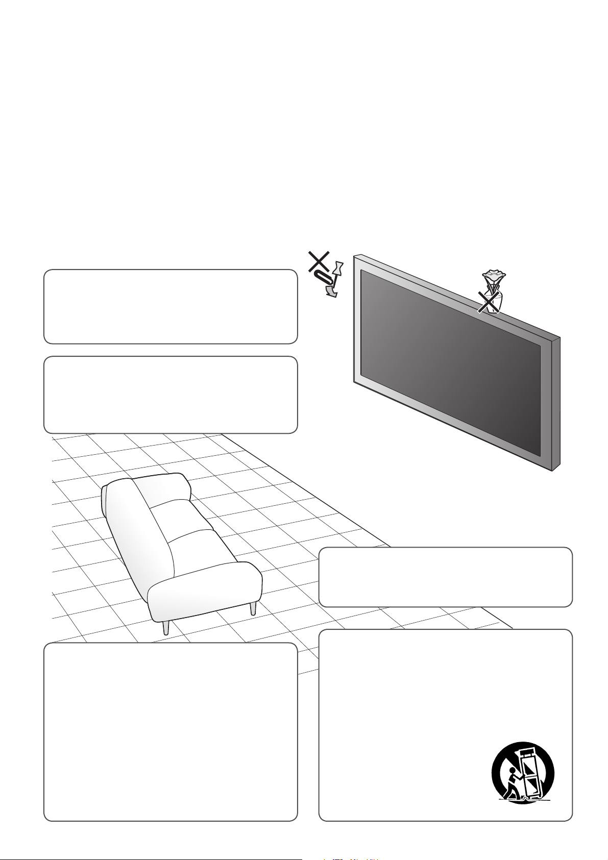
• Slots and openings in the cabinet are provided for
ventilation. These ensure reliable operation of the
product and protect it from overheating. These
openings must not be blocked or covered.
• The openings should never be blocked by placing
the product on bed, sofa, rug, or similar surface. It
should not be placed in a built-in installation such as a
bookcase or rack unless proper ventilation is provided
and the manufacturer’s instructions have been
adhered to.
• For proper ventilation, separate the product from
other equipment, which may prevent ventilation and
keep distance more than 10 cm (3 15/16 inches).
Do not attempt to service this product yourself, as
opening or removing covers may expose you to
dangerous voltages and other hazards. Refer all service
to qualifi ed service personnel.
• Do not place this product on an unstable cart, stand,
or table. The product may fall, causing serious injury
to a child or adult, and serious damage to the product.
The product should be mounted according to the
manufacturer’s instructions, and should use a mount
recommended by the manufacturer.
• When the product is used on
a cart, care should be taken to
avoid quick stops, excessive
force, and uneven surfaces
which may cause the product
and cart to overturn, damaging
equipment or causing possible
injury to the operator.
3
Page 4
Safety Precautions (cont.)
• Power-supply cords should be routed so that they are
not likely to be walked on or pinched by items placed
upon or against them. Pay particular attention to cords
at doors, plugs, receptacles, and the point where they
exit from the product.
• For added protection of this product during a lightning
storm, or when it is left unattended and unused for
long periods of time, unplug it from the wall outlet and
disconnect the cable system. This will prevent damage to
the product due to lightning and power line surges.
• Do not overload wall outlets, extension cords, or
convenience receptacles on other equipment as this can
result in a risk of fi re or electric shock.
• Use only the accessory cord designed for this product to
prevent shock.
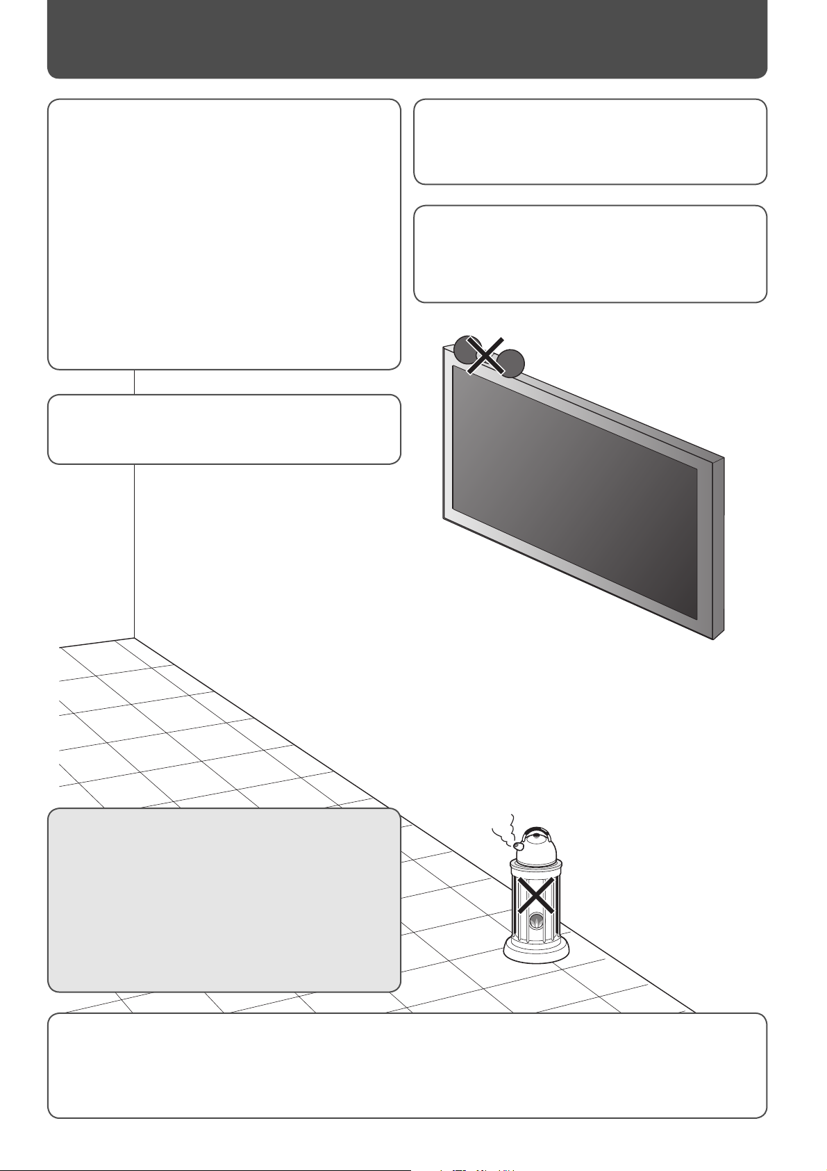
Do not place combustibles behind the cooling fan. For
example, cloth, paper, matches, aerosol cans or gas
lighters that present special hazards when over heated.
The product should be placed more than 30 cm (11 13/16
inches) away from heat sources such as radiators, heat
registers, stoves, and other products (including amplifi ers)
that produce heat.
• When connecting other products such as VCR’s and
personal computers, you should turn off the power of
this product for protection against electric shock.
• Do not use attachments not recommended by the
product manufacturer as they may be hazardous.
Maintenance
• Unplug this product from the wall outlet before
cleaning.
• Do not use liquid cleaners or aerosol cleaners. Use a
damp cloth for cleaning.
• Use a vacuum cleaner to get rid of the dust around the
intakes (all the openings) on the rear. If a vacuum is not
available, use a cloth and wipe it off . Failure to do so
will cause internal heat buildup and, therefore, cause
damage to the product.
• When replacement parts are required, be sure the service technician has used replacement parts specifi ed by the
manufacturer or with same characteristics as the original part. Unauthorized substitutions may result in fi re, electric
shock, or other hazards.
• Upon completion of any service or repairs to this product, ask the service technician to perform safety checks to
determine that the product is in proper operating condition.
4
Page 5

Table of Contents
Safety Precautions .............................................. 2
IMPORTANT SAFEGUARDS ........................................2
Parts Identifi cation ............................................. 6
Front panel ......................................................................6
Rear panel ........................................................................6
Remote control ..............................................................8
Installation .......................................................... 9
Connecting external speakers .............................. 10
Connections ...................................................... 11
Available signals ......................................................... 11
Daily Operations ............................................... 14
Turning on the main power ...................................14
Turning on the monitor ...........................................14
Selecting an input .....................................................14
Adjusting the volume ..............................................14
Changing the aspect ratio ...................................... 15
Displaying the current status ................................ 15
Selecting the picture mode ................................... 16
Selecting the audio mode ...................................... 16
Viewing Inputs A and B (analog RGB input)
at the same time —Dual Display .................... 16
Menu Operations .............................................. 17
Menu Confi guration—MAIN MENU ................ 18
Menu Confi guration—SET-UP MENU .............. 24
Setting the Power-on Lock ..................................... 30
How to Use External Control ............................ 31
Troubleshooting ............................................... 34
Self-diagnostic indication ....................................... 36
Specifi cations .................................................... 37
Checking the accessories
The following accessories are included with the monitor. Check for them. If any item is missing, please contact the dealer
where you have purchased the monitor.
• Remote control (RM-C2005)
• Power cord x 1
• D-sub 15 pin – BNC conversion cable x 1
• Batteries (AA/R6) x 2
• Ferrite cores x 2
NOTE
• Be sure to attach the supplied ferrite cores to the speaker cords when using external speakers to reduce interference from the monitor on
external equipment (see page 10).
5
Page 6
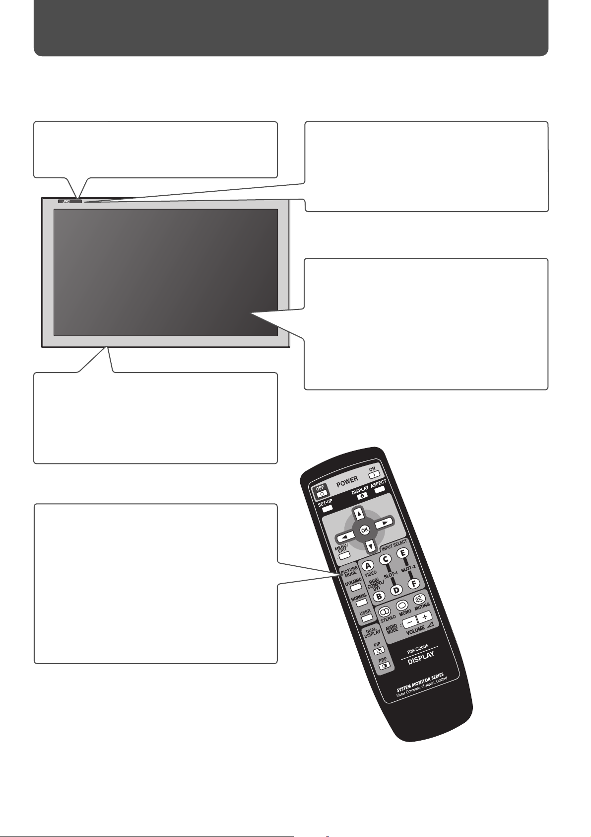
Parts Identifi cation
Front panel
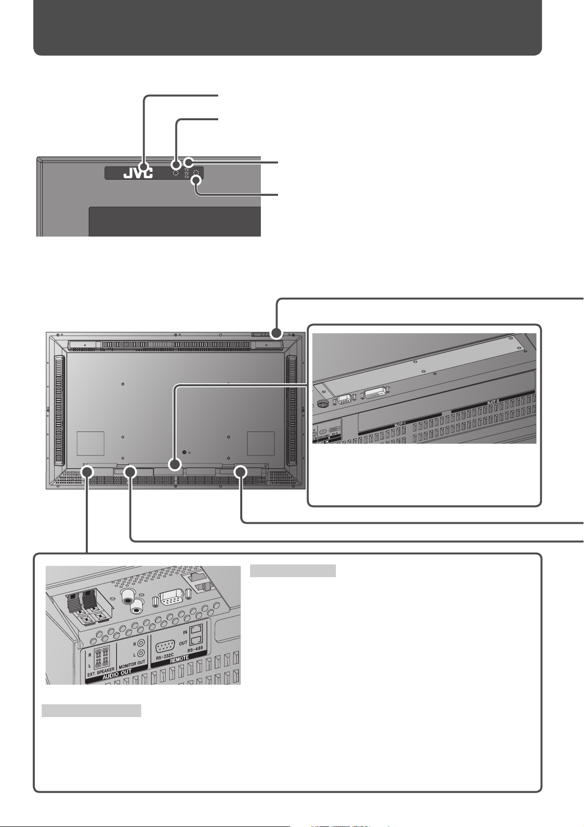
Remote sensor:
Eco sensor:
Rear panel
Point the front end of the remote control toward here.
Detects brightness of the room (see page 23).
Self-diagnostic lamps:
These lamps light/fl ash if something abnormal occurs with
the monitor (see page 36).
Power lamp:
When the monitor is turned off : Unlit.
When the monitor is turned on: Lights in green.
When the monitor is in sleep mode: Flashes in orange.
When the monitor is in standby mode: Lights in orange.
Input card slots (SLOT-1, SLOT-2):
Optional input cards can be installed in these slots.
• For details about input cards, refer to the
instructions of the input card.
REMOTE terminals
Connect external control equipment (see pages 12, 31 to 33).
RS-232C terminal: Connect to the RS-232C terminal of a
personal computer. For the control method
using this terminal, consult an authorized JVC
dealer.
RS-485 terminals:
IN terminal: Connect external control equipment.
OUT terminal: Connect another component to send out the
control signal coming into the IN terminal
(cascade connection).
AUDIO OUT terminals
Connect external speakers or audio equipment.
EXT. SPEAKER terminal: Connect external speakers (commercially available) (see page 10).
• To use this terminal, set “SPEAKER SELECT” on the main menu to “EXT. (external)” (see page 21).
MONITOR OUT terminals: Connect to the audio input terminals of audio equipment such as an amplifi er (see
page 12).
6
Page 7
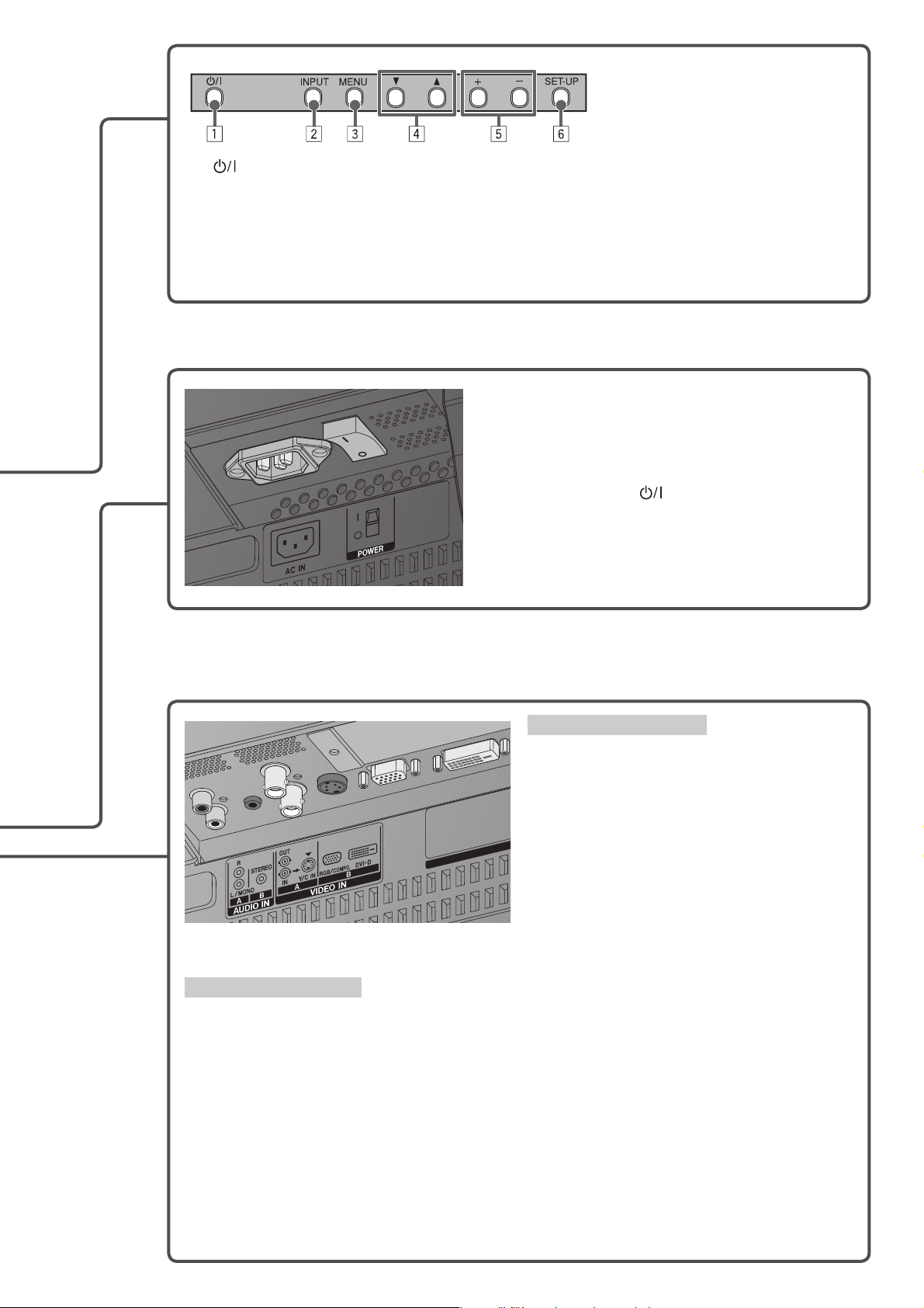
1 (Power) button: Turns the monitor on/off (see page 14).
2 INPUT button: Changes inputs (see page 14).
3 MENU button: Displays the main menu (see page 17).
4 5/∞ buttons: Selects an item on the menu (see page 17).
5 +/– buttons: Adjusts the volume level (see page 14).
• When the menu is displayed, adjusts the value (see page 17).
6 SET-UP button: Displays the set-up menu (see page 17).
AC IN terminal:
Connect the supplied power cord (see page 13).
POWER switch:
I : Turns on the main power. (The power can be
controlled by POWER ON/OFF buttons on the
remote control or button on the main unit.)
‡: Turns off the main power.
AUDIO IN A/B terminals
Connect audio output terminals of equipment
such as a VCR (see page 13).
AUDIO IN A terminal
R, L/MONO terminals (pin jack):
Connect to the audio output terminals of
the equipment connected to the VIDEO
IN A terminal. (Connect only the L/MONO
terminal for monaural sound.)
AUDIO IN B terminal
STEREO terminal (stereo mini jack):
Connect to the audio output terminals of
the equipment connected to the VIDEO IN
B terminal.
VIDEO IN A/B terminals
Connect video output terminals of equipment such as a VCR (see page 13).
VIDEO IN A terminal
IN terminal (BNC): Connect to the video output terminals of playback equipment such as a
VCR.
OUT terminal (BNC): Connect to the video input terminal of another monitor, etc.
Y/C IN terminal (Y/C): Connect to the S-video output terminal of playback equipment such as a
VCR.
• When both IN terminal and Y/C IN terminal are used, the input to the Y/C IN terminal has priority.
VIDEO IN B terminal
RGB/COMPO. terminal (D-sub 15-pin)*: Connect to the video output terminal of a personal
computer or playback equipment such as a VCR.
DVI-D terminal (DVI-D)*: Connect to the digital output terminal of a personal computer.
* When connecting to a personal computer, use a cable with ferrite cores and no longer than of 3 m (118 1/8”) to avoid
electromagnetic disturbance.
7
Page 8
Parts Identifi cation (cont.)
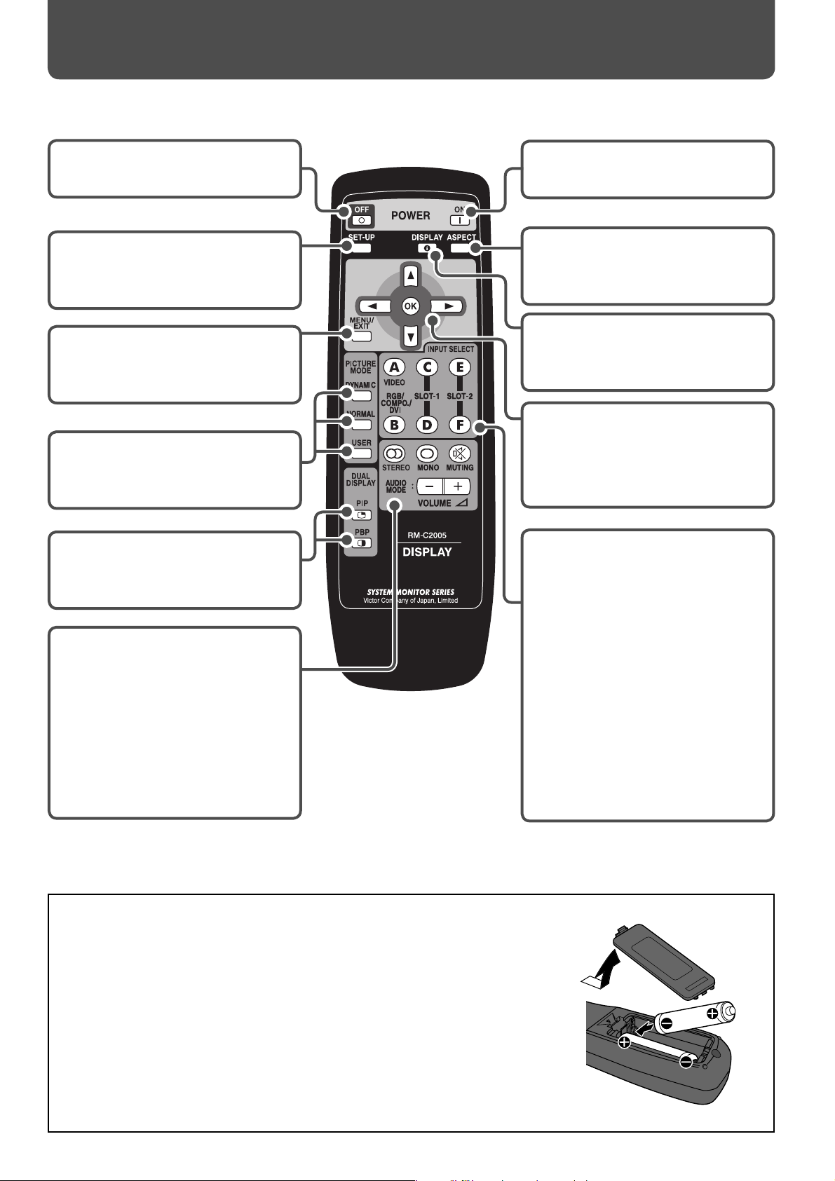
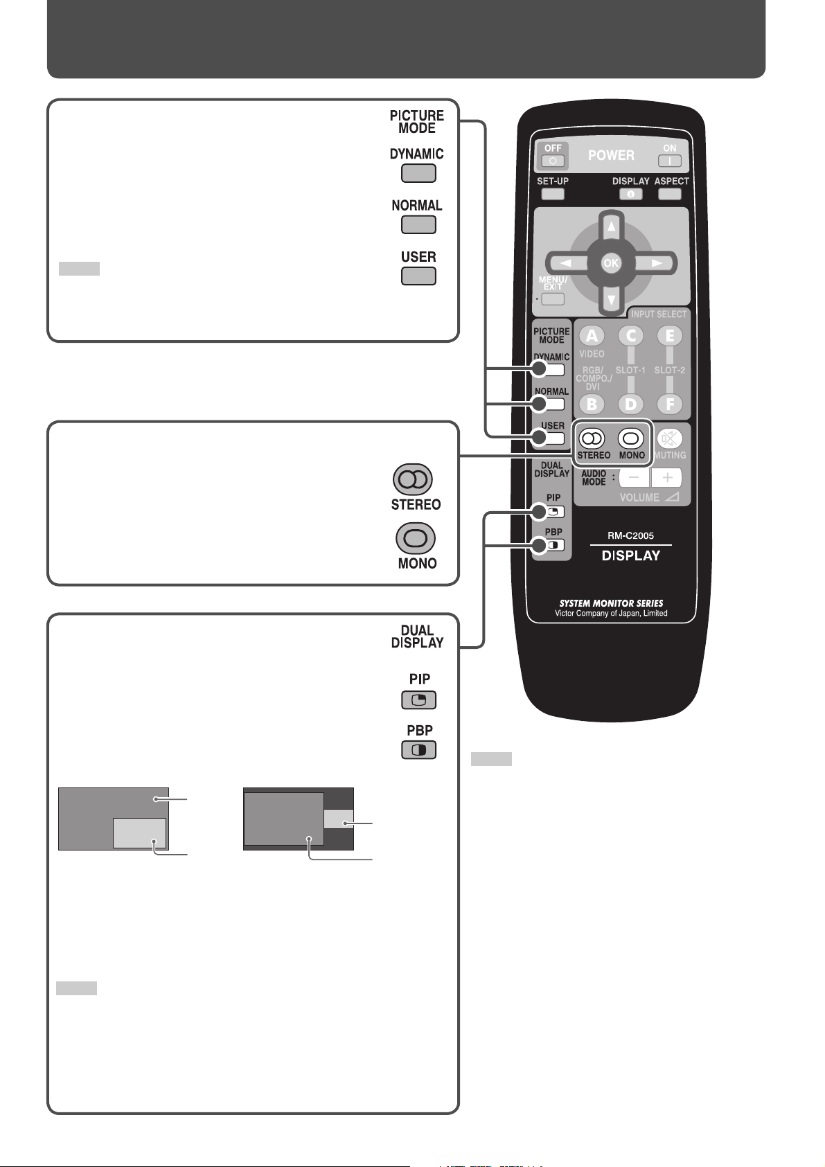
Remote control
POWER OFF button
Turns off the monitor (see page 14).
SET-UP button
Displays the set-up menu (see page
17).
MENU/EXIT button
Displays the main menu (see page
17).
PICTURE MODE buttons
Changes the picture mode (see
page 16).
DUAL DISPLAY buttons
Activates/deactivates the dual
display mode (see page 16).
AUDIO MODE buttons
VOLUME +/– buttons
Adjusts the volume level (see page
14).
STEREO, MONO buttons
Changes the audio mode (see page
16).
MUTING button
Turns off the volume immediately
(see page 14).
POWER ON button
Turns on the monitor (see page 14).
ASPECT button
Changes the aspect ratio (see page
15).
DISPLAY button
Displays the information of the
current input (see page 15).
5∞ 2 3 buttons
Operates the menu (see page 17).
OK button
Enters the password for the Poweron Lock (see page 30).
INPUT SELECT buttons
Selects the input (see page 14).
A (VIDEO) button
Selects the input to the VIDEO IN
A terminal (Input A).
B (RGB/COMPO./DVI) button
Selects the input to the VIDEO IN
B terminal (Input B).
C, D (SLOT-1) buttons
Selects the input to the optional
input card inserted in the slot 1
(Input C/D).
E, F (SLOT-2) buttons
Selects the input to the optional
input card inserted in the slot 2
(Input E/F).
Inserting the batteries
Use two AA/R6 dry cell batteries.
Insert the batteries from the · end, making sure the ª and · polarities are correct.
• Follow the warnings printed on the batteries.
• Battery life is about six months to one year, depending on how much you use
the remote control.
• The batteries we supply are only for setting up and testing your monitor,
please replace them as soon as you need to.
• If the remote control does not work properly, replace the batteries.
8
Page 9
Installation
Precautions
• When installing the monitor, be sure to use a dedicated stand unit or wall mounting unit, depending on your particular
case. Ask your dealer to install.
• When installing the monitor in a special way (for example, installing it diagonally), consult your dealer.
• Route the power cord and connection cables along the wall or fl oor corners to avoid walking on them.
• For good heat dissipation, try to leave the following distance of space (minimum) around the monitor (see diagram below).
• The ambient temperature of the installation place should be within the range of 0°C to 40°C (32°F – 104°F) (slightly variable
depending on ambient conditions for installation).
• When installing the monitor near the ceiling or similar location, the remote control may not work correctly because of
possible eff ects, such as refl ections, from the surroundings. If this happens, move the monitor where it is free from these
eff ects.
• Do not install the monitor in such a way that the monitor and other AV equipment aff ect each other adversely. (For
example, if a disturbed image or noise due to electromagnetic interference occurs, or if the infrared remote control
malfunctions, change the installation place.)
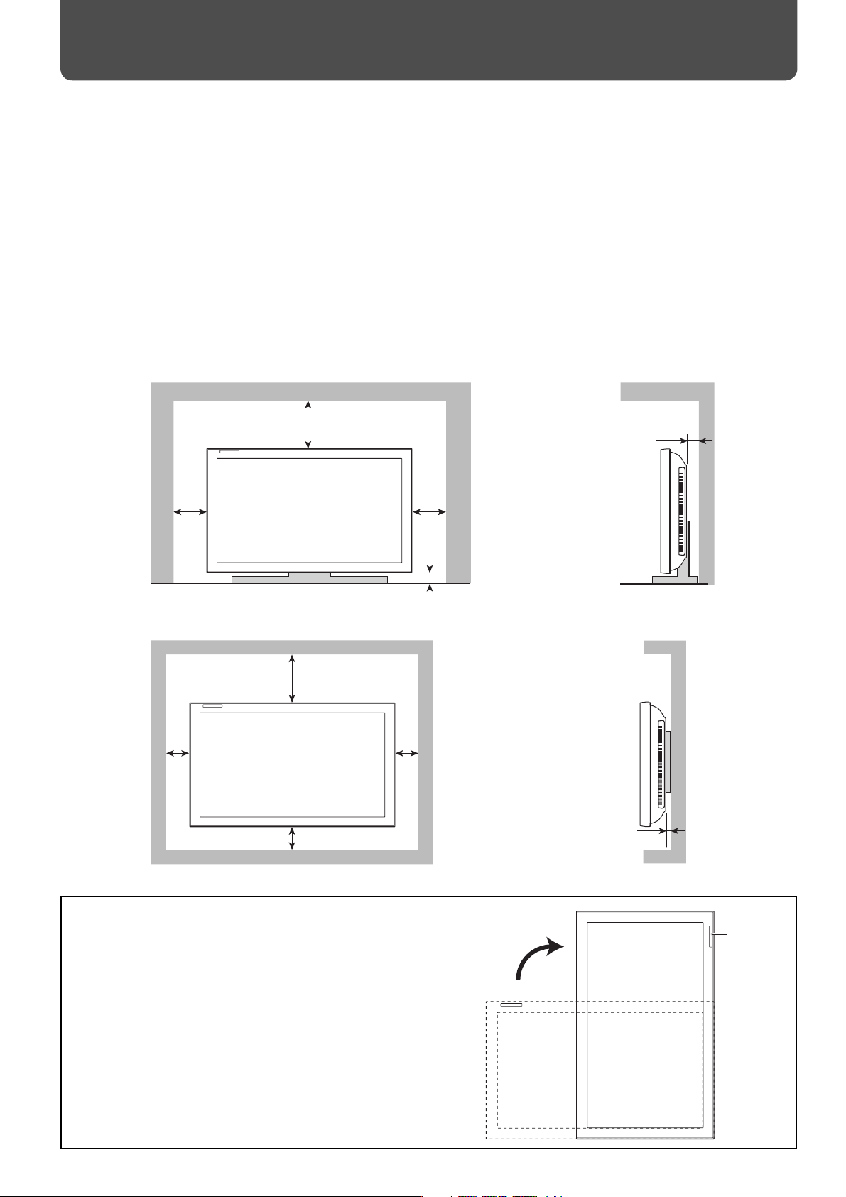
When installing the monitor on a stand
Front view Side view
200 (7 7/8)
150
(6)
Unit: mm (inch)
150
(6)
50 (2)
When mounting the monitor on the wall
Front view Side view
200 (7 7/8)
100
(4)
100
(4)
50 (2)
Unit: mm (inch)
100 (4)
When installing the monitor vertically
• Make sure to install the monitor in the direction illustrated on
the right.
• Set the speed of the internal cooling fan to “HIGH” (see “FAN
SPEED” on page 29).
15 (5/8)
Remote
sensor
9
Page 10
Installation (cont.)
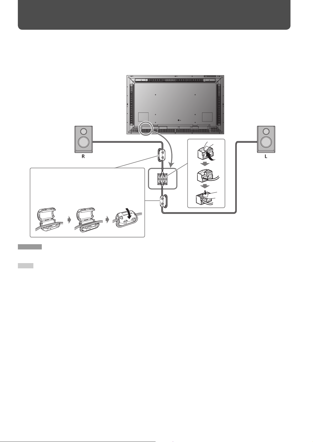
Connecting external speakers
You can connect commercial speakers of the following specifi cations to the EXT. SPEAKER terminal:
• Impedance: Between 6 Ω and 8 Ω
• Power handling capacity: More than 3 W
Speakers
(commercially available)
Ferrite core (supplied)
To reduce interference from the monitor on external
equipment, attach the supplied ferrite cores near to the
EXT. SPEAKER terminals on the rear panel of the monitor.
CAUTION
• Do not short-circuit 9 and ( speaker cords to each other. (Refer also to the instructions supplied with the speakers.)
NOTE
• When using the external speakers, set “SPEAKER SELECT” on the main menu to “EXT. (external)” (see page 21).
Speakers
(commercially available)
10
Page 11
Connections
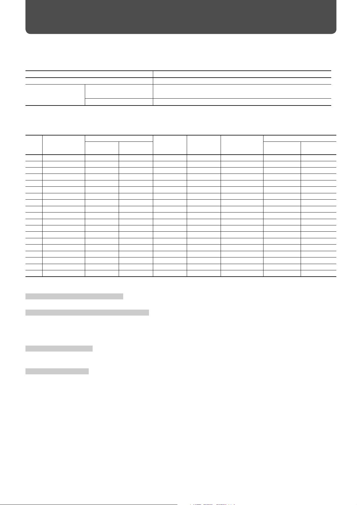
Available signals
The following signals can be input to this monitor.
Video signals
Terminal Available signals
VIDEO IN A terminals NTSC, PAL, SECAM, PAL60, NTSC4.43, PAL-M, PAL-N, BW (50 Hz/60 Hz)
VIDEO IN B (RGB/
COMPO.) terminal
* Select an appropriate setting for High-Defi nition signal (see “1080/1035“ on page 23).
Computer signals (Preset)
VIDEO IN B (RGB/COMPO., DVI-D) terminals
No. Signal name
1 PC98 640 400 24.8 56.4 Non-interlace √ —
2VGA400-70 640 400 31.5 70.1 Non-interlace √ —
3VGA480-60 640 480 31.5 59.9 Non-interlace √ √
4WVGA-60 852 480 31.5 59.9 Non-interlace √ —
5VGA480-72 640 480 37.9 72.8 Non-interlace √ —
6SVGA-60 800 600 37.9 60.3 Non-interlace √ √
7XGA-60 1024 768 48.4 60.0 Non-interlace √ √
8WXGA-60 1366 768 48.4 60.0 Non-interlace √ √
9XGA-70 1024 768 56.5 70.1 Non-interlace √ —
10 XGA-75 1024 768 60.0 75.0 Non-interlace √ —
11 XGA-85 1024 768 68.7 85.0 Non-interlace √ —
12 XGA+-75 1152 864 67.5 75.0 Non-interlace √ —
13 SXGA-60 1280 1024 64.0 60.0 Non-interlace √ √
14 SXGA-75 1280 1024 80.0 75.0 Non-interlace √ —
15 UXGA-60 1600 1200 75.0 60.0 Non-interlace √ —
16 MAC13” 640 480 35.0 66.7 Non-interlace √ —
17 MAC16” 832 624 49.7 74.6 Non-interlace √ —
18 MAC19” 1024 768 60.2 74.9 Non-interlace √ —
19 MAC21” 1152 870 68.7 75.1 Non-interlace √ —
Component signals 480/60i, 576/50i, 480/60p, 576/50p, 720/60p, 720/50p, 1080/60i
(1035/60i)*, 1080/50i, 1080/24psF
RGB signals 15 kHz/50 Hz, 15 kHz/60 Hz
Screen resolution Horizontal
Horizontal Vertical RGB/COMPO. DVI-D
frequency
(kHz)
Ver tical
frequency
(Hz)
Input terminal
Scan system
√ : Acceptable — : Not acceptable
Note for VIDEO IN A (IN, Y/C IN) terminals
• When both IN terminal and Y/C IN terminal are used, the input to the Y/C IN terminal has priority.
Note for VIDEO IN B (RGB/COMPO., DVI-D) terminals
Select the correct input for Input B on the main menu (see “INPUT CONFIGURATION” on page 21).
• When RGB signals are input to the RGB/COMPO. terminal: Set “INPUT B” to “ANALOG RGB.”
• When component signals are input to the RGB/COMPO. terminal: Set “INPUT B” to “COMPONENT.”
• When using the DVI-D terminal: Set “INPUT B” to “DVI.”
Note for component signals
• The monitor is compatible only with Y on sync signals. The monitor is not compatible with composite sync (Cs) and separated sync (HD/
VD) signals.
Note for computer signals
• When a signal other than those listed above is input, part of the picture may not be displayed or an unnecessary picture may appear.
• Any signal other than those listed above may not be displayed normally although it’s frequency is within the acceptable range.
Depending on the connected equipment, the monitor may not be compatible with composite sync (Cs) or G on sync signals.
•
• When a preset mode signal is input, the signal format is displayed on the screen. For other signals, the horizontal frequency and vertical
frequency are displayed.
• The DVI-D terminal can accept only No. 3, 6, 7, 8, and No. 13 signals.
• When the No. 3 and No. 7 signals are input, set “SAMPLING MODE” to “STD” on the set-up menu (see page 29).
• When the No. 4 and No. 8 signals are input, make the following settings:
– Set “SAMPLING MODE” to “WIDE” on the set-up menu (see page 29).
– Change the aspect ratio to “FULL” (see pages 15 and 19).
– Set the video card of the personal computer to “852 x 480” (for No. 4 signal)/“1366 x 768” (for No. 8 signal).
• When No. 12 to No. 15 and No. 19 signals are input, thin lines may become obscured because their signal frequencies are higher than the
screen resolution.
• The adjustment of the screen size and position is the setting common to the No. 10 and No. 18 signals. If you use both signals by
switching them, the adjustment of either signal may not be proper.
11
Page 12
Connections (cont.)
CAUTION
• Before making any connections, turn off all the equipment.
• DO NOT connect the power cord until all connections are completed.
• Use a cord whose plugs correctly match the terminals on this monitor and the equipment.
• Plugs should be fi rmly inserted; poor connections could cause noise.
• When unplugging a cord, be sure to grasp it’s plug and pull it out.
• Refer also to the user manual of each piece of equipment.
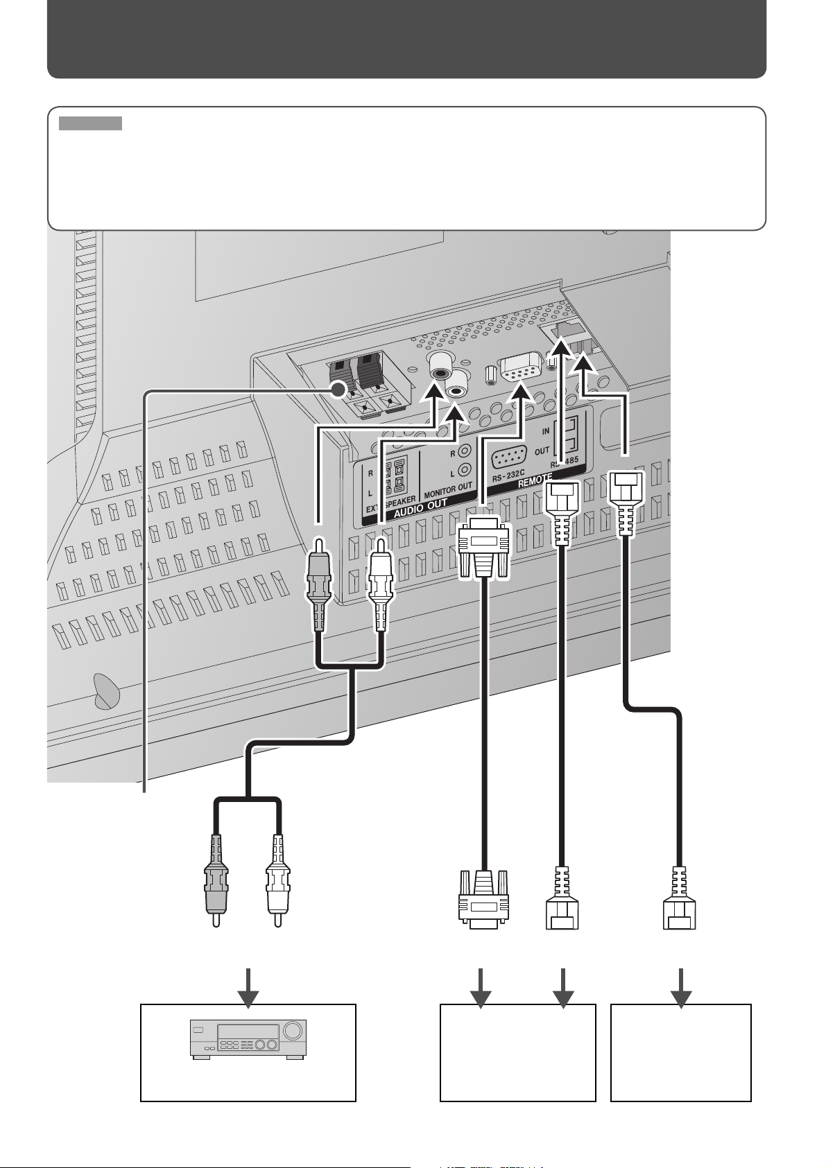
12
To external speakers
(See page 10.)
Stereo audio
cable
RL
To stereo audio
input terminals
Amplifi er, etc.
RS-232C cable
To RS-232C
terminal
External equipment used
to control the monitor
(See page 31.)
RJ-45 cable
To RS-485
output terminal
RJ-45 cable
To RS-485
input terminal
External control input
terminal of other
equipment
(See page 31.)
Page 13

Connect the VIDEO IN A OUT terminal to the video input terminal of another monitor, etc.
CAUTION
• Since the IN terminal and OUT terminal are loop-through terminals, the devices connected to the OUT terminal should be correctly
terminated. Otherwise, pictures become abnormally bright or the display screen gets aff ected abnormally.
or
Stereo audio
cable
BNC cable
RL
To stereo audio
output terminals
Playback component such as a VCR
To video output
terminal (BNC)
output terminal
S-video cable
To S-video
When all the connections are completed
D-sub 15 pin – BNC
conversion cable
Stereo mini jack cable
To audio
output
terminal
Playback component such as a PC
or VCR
To component
video output
terminal (BNC)
(supplied)
To RGB output
terminal
D-sub 15 pin cable
To digital
output terminal
DVI-D cable
Power cord (supplied)
To wall outlet
13
Page 14

Daily Operations
Turning on the main power
I : Main power on
‡ : Main power off
On the rear panel
Turning on the monitor
From the remote control:
To turn off the monitor, press POWER OFF.
On the main unit:
Each time you press the button, the power
turns on and off .
Selecting an input
From the remote control:
On the main unit:
Each time you press the button,
the input changes.
NOTE
• When “QUICK CHANGE” is set to “INPUT A&B,” you can change
Inputs A and B quickly (see “INPUT CONFIGURATION” on page 21).
Adjusting the volume
From the remote control:
On the main unit:
To turn off the volume immediately:
Pressing the button again resumes the
previous volume level.
•
When using the buttons on the main
unit, set “MUTING” to “ON” on the main
menu (see “AUDIO SETTING” on page 21).
14
• When the Control Lock is set to “ON” (see page 27),
you cannot use the buttons on the main unit.
• When the Power-on Lock is in set to “ON” (see page
30), you need to enter the password when turning
on the monitor.
Page 15
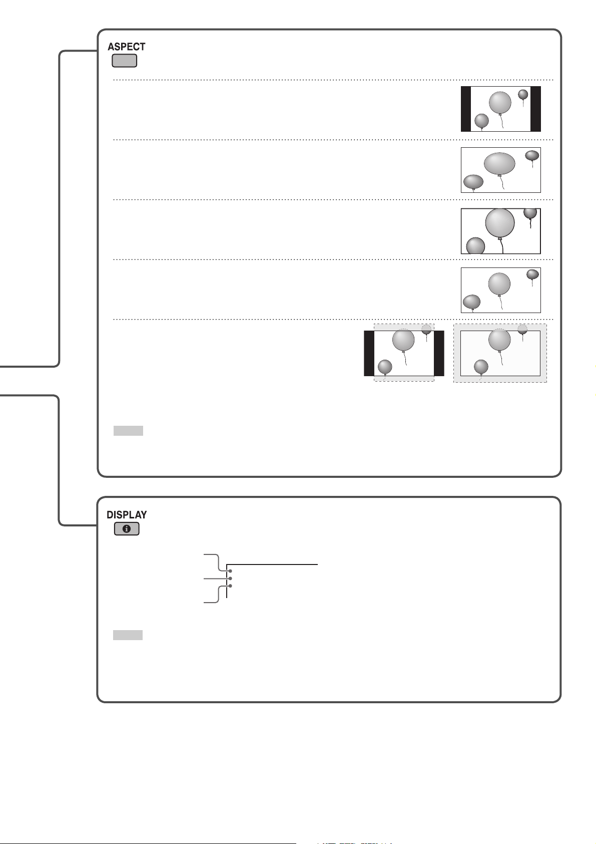
Changing the aspect ratio
Each time you press the button, the aspect ratio changes as follows:
REGULAR
Displays at conventional 4:3 aspect ratio.
FULL
Enlarges the picture of 4:3 aspect ratio horizontally.
• For the picture of 16:9 aspect ratio, the aspect ratio is not changed.
ZOOM
Enlarges the picture of 4:3 aspect ratio vertically and horizontally at the
same ratio.
PANORAMIC
Enlarges the picture of 4:3 aspect ratio horizontally to the extent that the
picture does not look abnormal.
<PC input ONLY>
REAL DOT
Displays center portion of the original picture input
from the computer (SXGA or UXGA signals) without
changing the number of pixels. (Some of the
picture will be cut off .)
Ex. For SXGA signals Ex. For UXGA signals
NOTE
• For some signals, the aspect ratio cannot be changed or some modes cannot be selected.
• When using the buttons on the main unit for changing the aspect ratio, use the main
menu (see “SIZE SETTING” on page 19).
Displaying the current status
The information of the current input is displayed on the screen.
Current input
Input type*
Input signal format*
1
2
INPUT A
VIDEO
NTSC
NOTE
• When “STATUS DISPLAY” on the main menu is set to “ON” (see page 23), the status is also displayed in the following
cases:
– When you turn on the monitor,
– When you change inputs, or
– When you change signal types.
*1 When Input C, D, E, or F is selected with an optional
input card inserted, the type of the card appears. When
no card is inserted, “NO CARD” appears.
2
When no signal is being input, “NO SYNC” appears.
*
When a signal this monitor does not support is being
input, “Out of range” appears.
15
Page 16
Daily Operations (cont.)
Selecting the picture mode
DYNAMIC: Suitable for displaying documents for
presentation.
NORMAL: Displays the original picture.
USER: You can adjust picture quality as you like
(see “PICTURE SETTING” on page 19).
NOTE
• You can adjust the picture quality, such as brightness, for
each picture mode. The setting you have made is stored (see
“PICTURE SETTING” on page 19).
Selecting the audio mode
To listen to stereo sounds
To listen to monaural sounds
• The stereo sounds are mixed to monaural sound.
Viewing Inputs A and B (analog RGB input) at the same time—Dual Display
You can view Inputs A and B (analog RGB input) at the
same time.
• This monitor supports 2 dual display modes.
PIP mode PBP mode
Main
window
Sub
window
• Each time you press the button, the corresponding dual display
mode turns on or off .
• When the dual display mode is activated, the current input is
displayed on the main window, and the other is displayed on
the sub window.
Sub window
Main window
NOTE
• When using the buttons on the main unit for operations
described on this page, use the main menu (see pages 19,
21, or 23).
NOTE
• The dual display mode is available only when analog RGB signals are
being input to Input B. For details, see page 23.
• You cannot change the input when the dual display mode is in use. To
change the inputs for the main and sub windows, deactivate the dual
display mode, change the input, and then activate the dual display mode.
• Use the main menu to adjust position and/or size of the sub window (see
“DUAL DISPLAY” on page 23).
16
Page 17
Menu Operations
On the main menu and set-up menu, you can make various adjustments, such as picture quality, or initial settings of the
monitor.
• For the confi guration of the main menu and a detailed description of each item, see pages 18 to 23.
• For the confi guration of the set-up menu and a detailed description of each item, see pages 24 to 30.
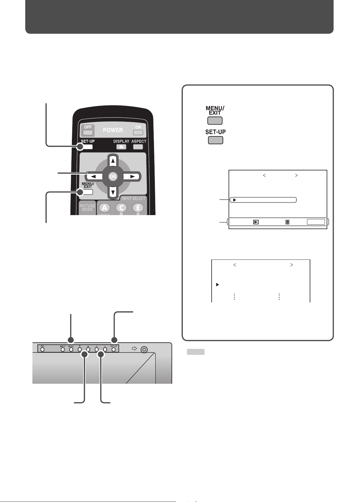
From the remote control
SET-UP
5 ∞ 2 3
MENU/EXIT
On the main unit
MENU
Works in the same way as MENU/
EXIT on the remote control.
SET-UP
1 Display the menu.
To display the main menu
To display the set-up menu
2 Press 5 ∞ to select an item, then press 3.
Ex.: When the main menu is displayed
MAIN MENU
:ENGLISH
SELECT:
EXIT:
MENU
Selected item
Operation
guide
PICTURE SETTING
SIZE SETTING
AUDIO SETTING
INPUT CONFIGURATION
FUNCTION SETTING
LANGUAGE
ENTER:
3 Press 5 ∞ to select an item, then press
2 3 to make adjustments.
FUNCTION SETTING
COLOR SYSTEM
MULTI DISPLAY
DUAL DISPLAY
STATUS DISPLAY
1080/1035
: NTSC
: OFF
: 1080
4 Press MENU/EXIT to return to the previous
menu.
• Pressing the button again exits the menu operation.
5∞ +/–
Works in the same way
as 2 3 on the remote
control.
NOTE
• For some items, adjustments will be made by pressing 2 3 in
step 2 .
17
Page 18
PICTURE SETTING
SIZE SETTING
AUDIO SETTING
INPUT CONFIGURATION
FUNCTION SETTING
LANGUAGE
MAIN MENU
H SIZE
H POSITION
V SIZE
V POSITION
DOT CLOCK
CLOCK PHASE
ASPECT
sub menu
reset
SIZE SETTING
: +01
: 00
: –02
: 00
: 00
: 00
: FULL
CONTRAST
BRIGHT
CHROMA
PHASE
SHARPNESS
BACK LIGHT
COLOR TEMP.
sub menu
PICTURE SETTING
PICTURE MODE
1/2
: NORMAL
: +01
: 00
: –02
: 00
: 00
: +10
: HIGH
reset
PICTURE SETTING
CTI/LTI
2/2
: OFF
:+01
H SIZE
:+01
H POSITION
:+01
DOT CLOCK
:+01
CLOCK PHASE
:+01
V SIZE
:+01
V POSITION
:+01
CONTRAST
:NORMAL
PICTURE MODE
Are you sure?
"YES" then
"NO" then
MENU
reset
key.
key.
:+01
BRIGHT
:+01
CHROMA
:+01
PHASE
:+01
BACK LIGHT
:HIGH
COLOR TEMP.
:+01
SHARPNESS
Are you sure?
"YES" then
"NO" then
MENU
reset
key.
key.
:ENGLISH
MENUMENU
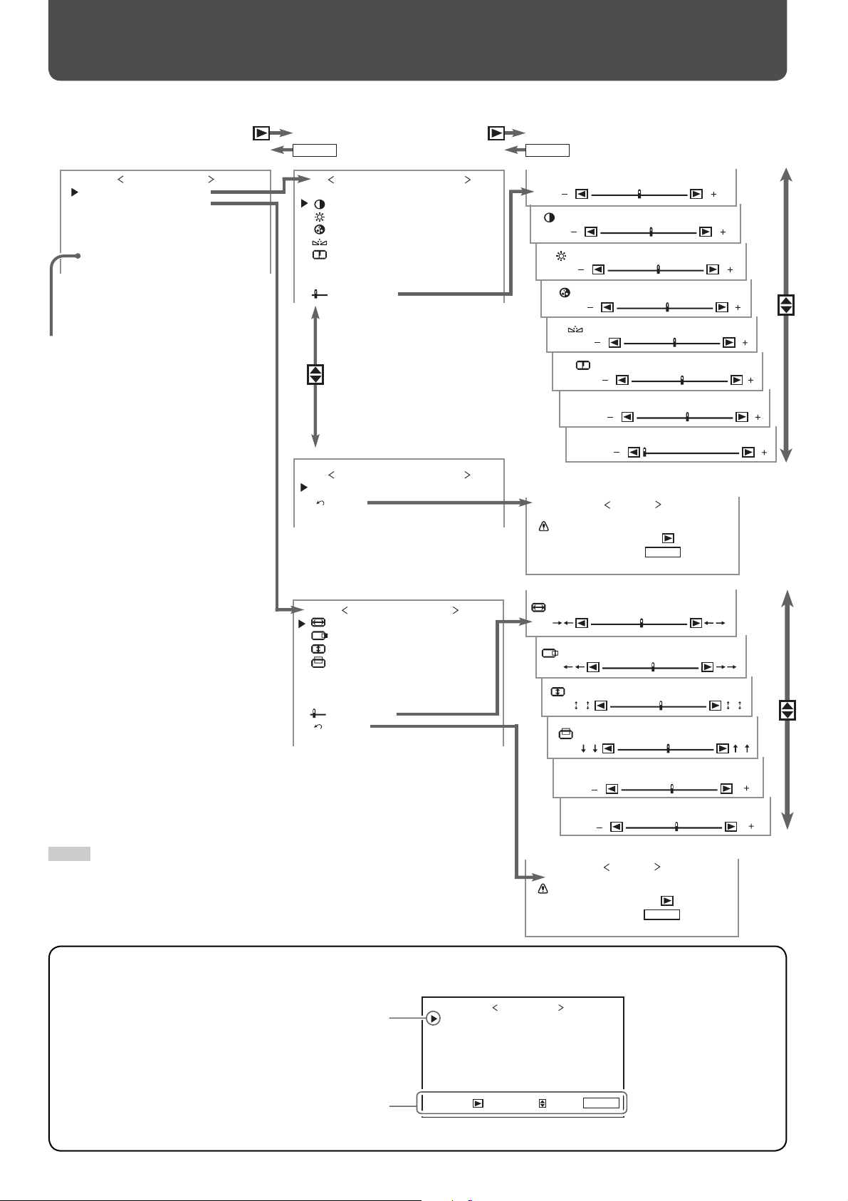
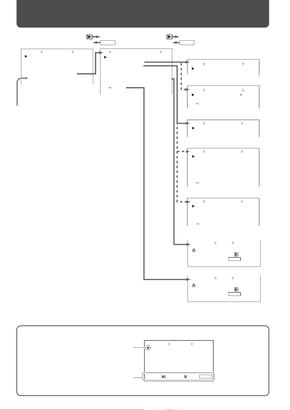
Menu Confi guration—MAIN MENU
On the main menu, you can make various adjustments and settings for picture, screen, and audio.
Select the menu language:
English, German, French, or
Russian
NOTE
• Some items may not appear on the menu depending on the input
(or the input card if it is attached) or the input signal. Those items are
not available to use.
Confi guration of the main menu screen
Cursor (selected item)
Operation guide
Shows the buttons for each operation.
18
PICTURE SETTING
SIZE SETTING
AUDIO SETTING
INPUT CONFIGURATION
FUNCTION SETTING
LANGUAGE
ENTER:
MAIN MENU
SELECT:
:ENGLISH
EXIT:
MENU
Page 19

PICTURE SETTING
Item To do Setting value
PICTURE MODE Selects a picture mode you want (see “Selecting the picture mode”
on page 16).
CONTRAST Adjusts contrast of the picture. –20 += 00 += +20
BRIGHT Adjusts the brightness of the picture. –20 += 00 += +20
CHROMA Adjusts the color density of the picture (except for RGB and BW
(50 Hz/60 Hz) signals).
PHASE Adjusts the color phase. –20 += 00 += +20
SHARPNESS Adjusts the outlines of the picture. –20 += 00 += +20
BACK LIGHT Adjusts the brightness of the display. –20 += 00 += +20
COLOR TEMP. Selects the color temperature. HIGH, MID, LOW, USER
sub menu Displays the adjustment bar which enables you to adjust the items in “PICTURE SETTING”
(except for “CTI/LTI”) while viewing the actual picture.
CTI/LTI Adjusts the clearness of the picture. OFF, 1, 2
reset Restores the default setting for all the items in “PICTURE SETTING.”
NOTE
• You can adjust the items in “PICTURE SETTING” for each picture mode. Select a picture mode you want to adjust fi rst. (The setting values are
stored.)
• “PHASE” does not appear on the menu for the following input signals:
– RGB, PAL, SECAM, BW (50 Hz/60 Hz)
• You can make the detailed settings of the color temperature using the set-up menu (see “COLOR TEMP.” on page 25).
DYNAMIC, NORMAL, USER
–20 += 00 += +20
SIZE SETTING
Item To do Setting value
H SIZE Adjusts the horizontal screen size.
H POSITION Adjusts the horizontal screen position.
V SIZE Adjusts the vertical screen size.
V POSITION Adjusts the vertical screen position.
DOT CLOCK Adjusts to eliminate stripes or fl ickering when analog signals
are being input from a computer. Use with “CLOCK PHASE.”
Normally, no adjustment is needed.
CLOCK PHASE Adjusts to eliminate stripes or fl ickering when analog signals
are being input from a computer. Use with “DOT CLOCK.”
Normally, no adjustment is needed.
ASPECT Selects the aspect ratio (see “Changing the aspect ratio” on
page 15).
sub menu Displays the adjustment bar which enables you to adjust H SIZE/POSITION, V SIZE/POSITION,
DOT CLOCK, and CLOCK PHASE while viewing the actual picture.
reset Restores the default setting for all the items in “SIZE SETTING.”
NOTE
• During the size and position adjustments, the picture may be distorted but this is not a malfunction.
• Size and position adjustments are related so that if one is set to a higher setting value, the other’s setting value will be reduced.
Varies depending on other
settings.
–10 += 00 += +10
–32 += 00 += +32
REGULAR, FULL, ZOOM,
PANORAMIC, REAL DOT
19
Page 20
reset
AUDIO SETTING
SPEAKER SELECT
MUTING
AUDIO
AUDIO SETTING
: INT.
: OFF
: STEREO
INPUT CONFIGURATION
Q UICK CHANGE
INPUT B
INPUT A
INPUT C
INPUT D
INPUT E
INPUT F
: INPUT A&B
: ANALOG RGB
: VIDEO(BNC)
: NO CARD
: NO CARD
: NO CARD
: NO CARD
reset
SPEAKER SELECT
MUTING
AUDIO L ch.
AUDIO R ch.
LEVEL METER SETTING
: INT.
: OFF
: 1ch
: 1ch
reset
LEVEL METER SETTING
LEVEL METER ch
BAR TYPE
BAR BRIGHTNESS
REFERENCE LEVEL
OVER LEVEL
:OFF
:3COLORS
:HIGH
:–20dB
:–8dB
Are you sure?
"YES" then
"NO" then
MENU
reset
key.
key.
Are you sure?
"YES" then
"NO" then
MENU
reset
key.
key.
PICTURE SETTING
SIZE SETTING
AUDIO SETTING
INPUT CONFIGURATION
FUNCTION SETTING
LANGUAGE
MAIN MENU
:ENGLISH
MENUMENU
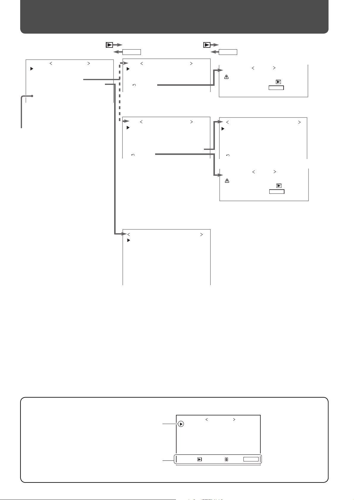
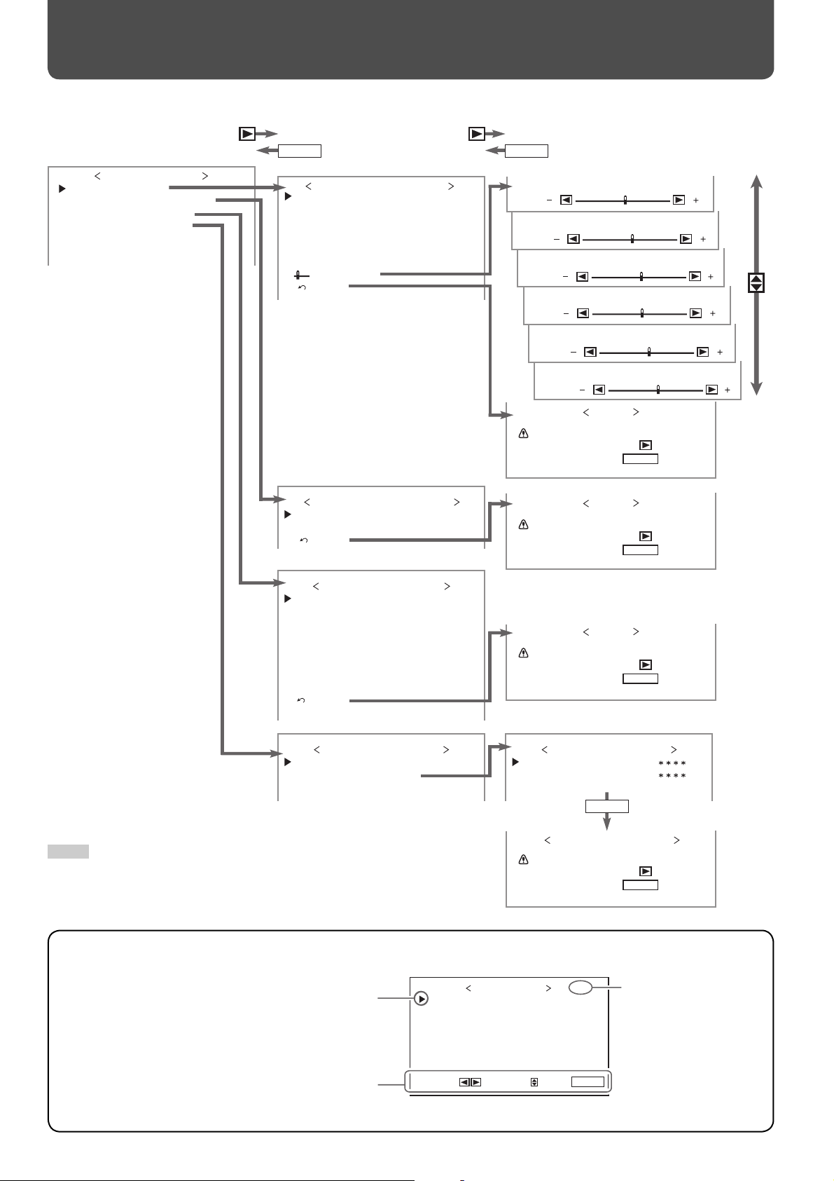
Menu Confi guration—MAIN MENU (cont.)
*1
*2
Select the menu language:
English, German, French, or
Russian.
Confi guration of the main menu screen
Cursor (selected item)
Operation guide
Shows the buttons for each operation.
20
*1 When no HD/SD SDI or SDI input card (option) is inserted.
*2 When an HD/SD SDI or SDI input card (option) is inserted.
ENTER:
PICTURE SETTING
SIZE SETTING
AUDIO SETTING
INPUT CONFIGURATION
FUNCTION SETTING
LANGUAGE
MAIN MENU
:ENGLISH
SELECT:
EXIT:
MENU
Page 21
AUDIO SETTING
Item To do Setting value
SPEAKER SELECT Selects the speakers you want to use. I
MUTING Turns the volume on or off . ON, OFF
AUDIO Changes the audio mode. STEREO, MONO
AUDIO L ch. Selects the left audio channel when the EMBEDDED AUDIO signal
is being input.
AUDIO R ch. Selects the right audio channel when the EMBEDDED AUDIO
signal is being input.
LEVEL METER SETTING Adjusts the audio level meter display for the EMBEDDED AUDIO signal when the HD/SD SDI or
SDI input card (option) is inserted (see “Example of the level meter display” below).
LEVEL METER ch Selects the audio channels used in the audio level meter
display. (The numbers indicate the audio channel. The
input level for the channels indicated on the left side of “:” is
displayed on the left side of the screen, and the input level for
the channels indicated on the right side of “:” is displayed on
the right side of the screen.)
BAR TYPE Selects the color of the audio level meter display. 3COLORS (3 colors to
BAR BRIGHTNESS Selects the brightness of the audio level meter display. HIGH, LOW
REFERENCE LEVEL Sets the standard input level. –20dB, –18dB
OVER LEVEL Sets the input level’s lower limit indicated in red for the
“3COLORS” display.
reset Restores the default setting for “LEVEL METER SETTING.”
reset Restores the default setting for all the items in “AUDIO SETTING.”
NT. (Internal speakers),
EXT. (External speakers)
1ch += 8ch
1ch += 8ch
OFF, 1:2, 12:34, 31:24,
123:456, 1–8
indicate variations in input
levels), W.100 (white), W.50
(half transparent)
–10dB, –8dB, –6dB, –4dB,
–2dB
INPUT CONFIGURATION
Item To do Setting value
QUICK CHANGE Sets if you want to change Inputs A and B quickly. OFF, INPUT A&B
INPUT B Selects the terminal and signal type you want to use for Input B. ANALOG RGB, DVI,
COMPONENT
INPUT A Displays the terminal being used for Input A (“VIDEO (BNC)” or
“VIDEO (Y/C)”).
INPUT C/D/E/F Shows the status of the input card slots. When no input card is
inserted, “NO CARD” appears.
—
—
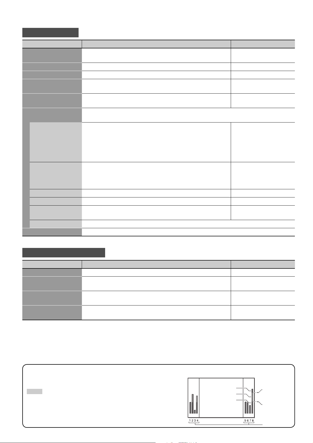
Example of the level meter display —Level indication and audio channels
Ex.: When “LEVEL METER ch” is set to “1–8” and ”BAR TYPE” is set to “3COLORS.”
NOTE
• When “BAR TYPE” is set to “W.100” or “W.50,” the standard input level set in the
“REFERENCE LEVEL” is displayed with the line indication. Input level set in “OVER
LEVEL” is not displayed.
• The audio channel bar with no signal input is displayed in white for the “3COLORS”
setting, and in gray for other settings.
Red
Yellow
Green
OVER LEVEL
REFERENCE
LEVEL
Audio channels
21
Page 22
COLOR SYSTEM
MULTI DISPLAY
DUAL DISPLAY
STATUS DISPLAY
1080/1035
SUB HOUR METER
ECO SENSOR
reset
HOUR METER
FUNCTION SETTING
: NTSC
: OFF
: 1080
: 00001H
: ON
: 60000H
MULTI SIZE
MULTI DISPLAY
: OFF
MODE
MAIN WINDOW
SUB. WINDOW
SIZE
H.POSI.
V.POSI.
reset
DUAL DISPLAY
: PIP
: INPUT-A
: INPUT-B
: LARGE–1
: 00
: 00
MODE
MAIN WINDOW
SUB. WINDOW
SPLIT LINE
reset
DUAL DISPLAY
: PBP
: INPUT-A
: INPUT-B
: CENTER
MODE
DUAL DISPLAY
: OFF
Are you sure?
"YES" then
"NO" then
MENU
reset
key.
key.
Are you sure?
"YES" then
"NO" then
MENU
reset
key.
key.
MULTI SIZE
MULTI POSI.
reset
MULTI DISPLAY
: 2 2
: 1
PICTURE SETTING
SIZE SETTING
AUDIO SETTING
INPUT CONFIGURATION
FUNCTION SETTING
LANGUAGE
MAIN MENU
:ENGLISH
MENUMENU
Menu Confi guration—MAIN MENU (cont.)
Select the menu language:
English, German, French, or
Russian.
When “MULTI SIZE” is “OFF.”
When “MULTI SIZE” is “2*2.”
When “MODE” is “OFF.”
When “MODE” is “PIP.”
When “MODE” is “PBP.”
Confi guration of the main menu screen
Cursor (selected item)
Operation guide
Shows the buttons for each operation.
22
PICTURE SETTING
SIZE SETTING
AUDIO SETTING
INPUT CONFIGURATION
FUNCTION SETTING
LANGUAGE
ENTER:
MAIN MENU
SELECT:
:ENGLISH
EXIT:
MENU
Page 23

FUNCTION SETTING
Item To do Setting value
COLOR SYSTEM Selects the color system. When you cannot view pictures correctly
with “AUTO,” select an appropriate option according to the current
input.
MULTI DISPLAY Sets the multiple monitor usage (see “Example of the multiple monitor setting” below).
MULTI SIZE Activates/deactivates the multiple monitor usage (2 monitors
horizontally * 2 monitors vertically).
MULTI POSI. Sets the position of this monitor when “MULTI SIZE” is set to
“2*2.”
reset Restores the default setting for “MULTI DISPLAY.”
DUAL DISPLAY Sets the dual display mode (see “Viewing Inputs A and B (analog RGB input) at the same
time—Dual Display” on page 16).
MODE Selects the dual display mode. OFF, PIP, PBP
MAIN WINDOW Displays the input for the main window (“INPUT-A” or “INPUT-
B”).
SUB. WINDOW Displays the input for the sub window (“INPUT-A” or “INPUT-B”). —
SIZE Adjusts the size of the sub window (only for PIP mode). SMALL-2, SMALL-1,
H.POSI./V.POSI. Adjusts the horizontal and vertical position of the sub window
(only for PIP mode).
SPLIT LINE Adjusts the position of the border between the main window
and sub window (only for PBP mode).
reset Restores the default setting for “DUAL DISPLAY.”
STATUS DISPLAY Sets if you want the information of the current input to be
displayed on the screen (see “Displaying the current status” on
page 15).
1080/1035 Selects a High-Defi nition signal type (1080/60i or 1035/60i) for the
component signal to view the picture correctly.
SUB HOUR METER Displays the hours of current use (unit: hour). You can reset only this item.
ECO SENSOR Sets the eco sensor which enables you to adjust the brightness of
the screen automatically according to the brightness of the room.
reset Restores the default setting for the items in “FUNCTION SETTING” except for “MULTI DISPLAY,”
“DUAL DISPLAY,” and “HOUR METER.”
HOUR METER Displays the total hours of use (unit: hour). This item is used for maintenance of the monitor.
This item cannot be reset.
AUTO, NTSC, PAL, SECAM,
N4.43, PAL M, PAL N, PAL60
OFF, 2*2
1 += 4
—
LARGE-1, LARGE-2
–20 += 00 += +20
RIGHT–2, RIGHT–1, CENTER,
LEFT–1, LEFT–2
OFF, ON
1080, 1035
ON, OFF
NOTE
• The dual display mode is available only when “MULTI SIZE” is set to “OFF.”
• “MULTI DISPLAY” is not displayed on the menu when the dual display mode is in use.
Available signals for the dual display mode
The dual display mode can be activated only when one of the following signals is being input to Input A and B.
• Input A: NTSC, PAL, SECAM, PAL-M, PAL-N, PAL60, NTSC4.43, BW (50 Hz/60 Hz)
• Input B (only analog RGB): VGA480-60, WVGA-60, XGA-60, WXGA-60
Example of the multiple monitor setting
Ex.: When “MULTI SIZE” is set to “2*2” and ”MULTI POSI.” is set to “2.”
This monitor
12
34
23
Page 24
COLOR TEMP.
NO SYNC FUNCTION
REMOTE SYSTEM
POWER ON LOCK
TIMER
VCR ADJ. : 00
R DRIVE
G DRIVE
B DRIVE
R CUT OFF
G CUT OFF
B CUT OFF
sub menu
reset
SET-UP MENU
COLOR TEMP.:HIGH
1/2
: 000
: 000
: 000
: 000
: 000
: 000
NO SYNC FUNCTION
NO SYNC DISPLAY
DELAY TIME
reset
: RED
: 5s
POWER ON LOCK
POWER ON LOCK
PASS ID SETTING
POWER ON LOCK
: OFF
PASS ID SETTING
ENTER PASS ID
REENTER PASS ID
:
:
Are you sure?
"YES" then
"NO" then
MENU
reset
key.
key.
PAS S ID OK?
"YES" then
"NO" then
MENU
key.
key.
REMOTE SYSTEM
REMOTE IN SEL.
CNT.RJ45 OUT
CNT.RJ45 IN
PORT F1
PORT F2
PORT F3
PORT F4
PORT F5
reset
: RJ-45
: IR OUT
: MAKE
: INP. A
: INP. C
: POWER
: ASPECT
: – – –
Are you sure?
"YES" then
"NO" then
MENU
reset
key.
key.
Are you sure?
"YES" then
"NO" then
MENU
reset
key.
key.
:000
B DRIVE
:000
G DRIVE
:000
R DRIVE
:000
B CUT OFF
:000
G CUT OFF
:000
R CUT OFF
MENUMENU
MENU
Menu Confi guration—SET-UP MENU
On the set-up menu, you can change various settings such as color temperature and timer.
NOTE
• Some items may not appear on the menu depending on the input
(or the input card if it is attached) or the input signal. Those items are
not available to use.
Confi guration of the set-up menu screen
Cursor (selected item)
COLOR TEMP.
NO SYNC FUNCTION
REMOTE SYSTEM
POWER ON LOCK
TIMER
VCR ADJ. :00
SET-UP MENU 1/2
Page
24
Operation guide
ADJUST:
Shows the buttons for each operation.
SELECT:
EXIT: MENU
Page 25
COLOR TEMP.
Item To do Setting value
R DRIVE, G DRIVE,
B DRIVE
R CUT OFF, G CUT OFF,
B CUT OFF
sub menu Displays the adjustment bar which enables you to adjust the drive level and cut-off point while
reset Restores the default setting for all the items in “COLOR TEMP.”
NOTE
• Adjust the color temperature after selecting color temperature (HIGH, MID., LOW, or USER) on the main menu (see “PICTURE SETTING” on page
19).
Adjusts the drive level of each color (red, green, and blue). MIN += 000 += MAX (in
512 grades)
Adjusts the cut-off point of each color (red, green, and blue). MIN += 000 += MAX (in
512 grades)
viewing the actual picture.
NO SYNC FUNCTION
Item To do Setting value
NO SYNC DISPLAY Selects the screen color (or sleep mode) when no signal is being
input.
DELAY TIME Sets the time to change the screen color (or sleep mode) set in
“NO SYNC DISPLAY” above after signals stops being input.
reset Restores the default setting for all the items in “NO SYNC FUNCTION.”
OFF, SLEEP (sleep mode),
RED, GREEN, BLUE, GRAY
5s, 1min., 30min.
REMOTE SYSTEM
Item To do Setting value
REMOTE IN SEL. Selects the input terminal used for external control. D-sub9, RJ-45
CNT. RJ45 OUT Selects the external control method for RS-485 OUT terminal. RS485, IR OUT
CNT. RJ45 IN Selects the external control method for RS-485 IN terminal. RS485, MAKE, TRIG., SET
PORT F1 – PORT F5 Assigns the control function to the RS-485 IN terminal’s pins (1 to
5) when selecting “SET” in “CNT. RJ45 IN” above.
reset Restores the default setting for all the items in “REMOTE SYSTEM.”
NOTE
• For details about external control, see pages 31 to 33.
INP. A – INP. F, POWER,
ASPECT, MUTING, PIP, PBP,
– – – (no function)
POWER ON LOCK
Item To do Setting value
POWER ON LOCK Activates/deactivates the Power-on Lock. When this function is
activated, the monitor cannot be turned on without entering the
password set in “PASS ID SETTING” below.
PASS ID SETTING Sets the password for the Power-on Lock. 4 characters
ON, OFF
NOTE
• For details about the Power-on Lock, see page 30.
25
Page 26

Menu Confi guration—SET-UP MENU
PRESENT TIME
POWER-ON SET
POWER-ON TIME
POWER-OFF SET
POWER-OFF TIME
reset
SET-UP MENU
TIMER
1/2
CONTROL LOCK
POWER ON DELAY
SYNC TERM.
FAN SPEED
I/P MODE
SAMPLING MODE
reset
all reset
MODEL
VER.
SET-UP MENU
2/2
: 14:25
: ON
: 08:16
: ON
: 21:20
: OFF
: FAST
: HIGH
: HIGH
: MODE1
: STD
: GM-H40L1G
: A
TIMER
PRESENT TIME
HOURS
MINUTES
: 14:25
: 14
: 25
TIMER
POWER-ON TIME
HOURS
MINUTES
: 08:16
: 08
: 16
TIMER
POWER-OFF TIME
HOURS
MINUTES
: 21:20
: 21
: 20
Are you sure?
"YES" then
"NO" then
MENU
reset
key.
key.
COLOR TEMP.
NO SYNC FUNCTION
REMOTE SYSTEM
POWER ON LOCK
TIMER
VCR ADJ. : 00
MENUMENU
(cont.)
Confi guration of the set-up menu screen
Cursor (selected item)
26
Operation guide
Shows the buttons for each operation.
COLOR TEMP.
NO SYNC FUNCTION
REMOTE SYSTEM
POWER ON LOCK
TIMER
VCR ADJ. :00
ADJUST:
SET-UP MENU 1/2
SELECT:
EXIT: MENU
Page
Page 27
TIMER
Item To do Setting value
PRESENT TIME Sets the clock.
HOURS Sets the hour. 00 += 23
MINUTES Sets the minute. 00 += 59
POWER-ON SET Activates/deactivates the power-on timer. ON, OFF
POWER-ON TIME Sets the time to turn on the monitor.
HOURS Sets the hour. 00 += 23
MINUTES Sets the minute. 00 += 59
POWER-OFF SET Activates/deactivates the power-off timer. ON, OFF
POWER-OFF TIME Sets the time to turn off the monitor.
HOURS Sets the hour. 00 += 23
MINUTES Sets the minute. 00 += 59
reset Restores the default setting for all the items in “TIMER.”
VCR ADJ.
Adjusts when the picture played back on a VCR is distorted. (Depending on the condition of the connected VCR or the
playback tape, the picture quality may not be improved.)
Setting value: –05 += 00 += +05
CONTROL LOCK
Activates/deactivates the Control Lock. When this function is activated, you cannot operate the monitor with the buttons on
the main unit.
Setting value: ON, OFF
NOTE
• You can use the remote control and external control while the control lock is set. To release the lock, use the remote control.
POWER ON DELAY
Sets the time when the power supply to the monitor’s circuits (excluding the micro computers) starts after the power button
is pressed.
Setting value: OFF, FAST, SLOW
NOTE
• If you are going to turn several monitors on at the same time, it is recommended to apply “SLOW” to some of the monitors to control rush
current.
SYNC TERM.
Sets the resistance of Horizontal sync/Composite sync signal and Vertical sync signal when the component/RGB input card
(option) is inserted. Normally, select “HIGH” (1 kΩ). If you see pictures fl ickering or blurring on the screen because of a long
connecting cord, set this to “LOW” (75 Ω).
Setting value: HIGH, LOW
NOTE
• When a video input card (option) is inserted, “SYNC SELECT” appears. Set the sync signal to use —INT. (sync signal included in the video signal)
or EXT. (external sync signal).
27
Page 28

Menu Confi guration—SET-UP MENU
(cont.)
SET-UP MENU
COLOR TEMP.
NO SYNC FUNCTION
REMOTE SYSTEM
POWER ON LOCK
TIMER
VCR ADJ. : 00
SET-UP MENU
CONTROL LOCK
POWER ON DELAY
SYNC TERM.
FAN SPEED
I/P MODE
SAMPLING MODE
reset
all reset
MODEL
VER.
: GM-H40L1G
: A
: OFF
: FAST
: HIGH
: HIGH
: MODE1
: STD
1/2
2/2
MENU
Are you sure?
"YES" then
"NO" then
Are you sure?
"YES" then
"NO" then
reset
MENU
all reset
MENU
key.
key.
key.
key.
Confi guration of the set-up menu screen
Cursor (selected item)
Operation guide
Shows the buttons for each operation.
28
COLOR TEMP.
NO SYNC FUNCTION
REMOTE SYSTEM
POWER ON LOCK
TIMER
VCR ADJ. :00
ADJUST:
SET-UP MENU 1/2
SELECT:
Page
EXIT: MENU
Page 29

FAN SPEED
Sets the speed of the internal cooling fan. When installing the monitor vertically, select “HIGH.”
Setting value: HIGH, LOW
I/P MODE
Select a mode with which you can view the least noise on the screen.
Setting value: MODE1, MODE2, MODE3
SAMPLING MODE
Sets the sampling mode for the signals input from the computer to reduce noise and display thin vertical lines of the picture
more clearly. Select “STD” for VGA480-60 or XGA-60, and “WIDE” for WVGA-60 or WXGA-60. (This item is not displayed for
other signals.)
Setting value: STD, WIDE
reset
Restores the default setting for all the items in the set-up menu.
all reset
Restores the default setting for all the items in the main menu and set-up menu except the use time (“HOUR METER”).
The power is turned off , then turned on again automatically.
MODEL, VER.
Displays the model name and version of the monitor. This item is used for maintenance of the monitor.
29
Page 30

Menu Confi guration—SET-UP MENU
POWER ON LOCK
PLEASE ENTER
PASS ID :
ENTER PASS ID :
REENTER PASS ID :
PASS ID SETTING
0
(cont.)
Setting the Power-on Lock
When the Power-on Lock is set to “ON,” you need to enter the password when turning on the monitor.
Without entering the correct password, you cannot perform any operation except for entering the password and turning off
the monitor.
7 To set the password
Enter a password of 4 characters.
Available characters: 0 – 9, A – Z, a – z
Remote control ONLY
1 Select “PASS ID SETTING” on the POWER ON LOCK sub
menu of the set-up menu.
2 Enter a password.
See “How to enter a password” below.
3 Press OK.
The cursor moves to the second line.
4 Enter the password again for confi rmation, then press
OK.
• If the password is diff erent from the one entered in step 2,
“PASS ID NG!” appears and the POWER ON LOCK sub menu is
displayed. In this case, repeat from step 1.
How to enter a password
To enter a password, follow the procedure below.
7 To activate the Power-on Lock
1 Select “POWER ON LOCK (: OFF)” on the POWER ON
LOCK sub menu of the set-up menu.
2 Press 3.
The Power-on Lock is set to “ON.”
• When turning on the monitor, the following message
appears. Enter the password (see “How to enter a password”
on the left).
POWER ON LOCK
PLEASE ENTER
PASS ID :
7 To deactivate the Power-on Lock
1 Select “POWER ON LOCK (: ON)” on the POWER ON
LOCK sub menu of the set-up menu.
2 Press 3.
The following message appears.
Ex.: Password setting screen
Remote control ONLY
1 Press 5∞ to select a character.
• The digit currently selected fl ashes, and “*” is displayed for
other digits.
2 Press 2 3 to edit the next digit.
3 Press OK after entering all digits.
DO NOT forget the password!
If you forget the password, consult your dealer.
3 Enter the password.
See “How to enter a password” on the left.
• If the password is wrong, “PASS ID NG!” appears. Enter the
correct password.
30
Page 31

How to Use External Control
7 About the external control
This monitor has two external control terminals as follows:
• RS-232C terminal: For operation using this terminal, consult your dealer.
• RS-485 terminals: You can select the external control system in “REMOTE SYSTEM” on the set-up menu (see “CNT. RJ45
OUT” and “CNT. RJ45 IN” on page 25).
(1) Serial communication: Controls the monitor by a personal computer or a dedicated controller (see page 32).
(2) IR OUT system: Controls other equipment by using the remote control supplied with this monitor.
(3) MAKE (make contact system): Controls the function by short-circuiting the corresponding pin terminal to the GND pin
terminal, or disconnecting (opening) it (see page 33).
(4) TRIG. (trigger system): Controls the function by inputting the pulse signal instantaneously to the corresponding
pin terminal (see page 33).
Set the input/output terminals correctly according to the system you use (see “REMOTE SYSTEM” on page 25).
Control system “REMOTE IN SEL.” setting “CNT. RJ45 OUT” setting “CNT. RJ45 IN” setting
RS-232C D-sub9 RS485 Any
Serial communication RJ-45* RS485 RS485
D-sub9* RS485 Any
IR OUT system Any IR OUT Any
MAKE system RJ-45 RS485 MAKE
TRIG. system RJ-45 RS485 TRIG.
* For the monitor connected to the external control equipment, set “REMOTE IN SEL.” according to the actual connection. Set other monitors by
following the setting of the serial communication with “REMOTE IN SEL.” set to “RJ-45” in the table above.
NOTE
• Control priority is as follows:
MAKE or TRIG. (trigger) system > RS-485 system > Buttons on the remote control or the main unit
• While the Control Lock is in use, you can use external control.
<Serial communication>
Several monitors can be controlled by connecting their RS-485 IN and OUT terminals. See also page 32.
Personal computer
or a dedicated
controller
RS-485 IN or
RS-232C
<IR OUT system>
Control signals from the remote control are sent to external equipment via the RS-485 OUT terminal.
RS-485
OUT
RS-485 IN RS-485 OUT RS-485 IN RS-485 OUT
Karaoke
component, etc.
RS-485 OUT
Remote control (supplied)
<MAKE/TRIG. system>
You can control the monitor by a personal computer or a dedicated controller*. See also page 33.
* External control unit is not commercially available. Consult your dealer if you need a dedicated controller.
31
Page 32
How to Use External Control (cont.)
1234 5678
7 Using the serial communication
You can control the monitor from a personal computer or a dedicated controller via the RS-485 or RS-232C terminal. For
details on operating the monitor from the personal computer or the dedicated controller, consult your dealer.
Input terminal Cable Specifi cation Communications specifi cations
RS-485 Prepare a straight cable with
a RJ-45 connector.
RS-232C Prepare a straight cable with
a RS-232C connector.
<RS-485 terminal>
This is a female terminal.
<RS-232C terminal>
Baud Rate: 4800/9600/19200 (factory pre-set; 4800)
See the table
below.
Data Bits: 8 bits
Parity: No parity
Stop Bits: 1 bit
Communication Cord: ASCII Cord
Pin No. IN terminal signal OUT terminal signal
1 TXD + TXD +
2 TXD – TXD –
3 RXD + RXD +
4 NC NC
5 NC IR. OUT
6 RXD – RXD –
7 5 V power* NC
8 GND GND
* The 5V power supply of the 7th terminal is for the controller
exclusively for this monitor. Do not use it for other devices.
This is a female terminal.
Pin No. Signal
1 —
2 RD (Receive Data)
3 TD (Transmit Data)
4 —
5 GND (Ground)
6 —
7 —
8 —
9 —
32
Page 33
How to Use External Control (cont.)
1234 5678
7 Using the MAKE/TRIG. system
The RS-485 IN terminal is confi gured as follows. You can assign the functions to each pin terminal by setting “REMOTE
SYSTEM” (see “PORT F1 – PORT F5” on page 25).
Pin No. Pin name
1 PORT F1
2 PORT F2
3 PORT F3
This is a female terminal.
To assign the functions to the pin terminals
For the operation procedure, see page 17.
1. Select “REMOTE SYSTEM” on the set-up menu.
2. Set “CNT. RJ45 IN” to “SET.”
3. Select a pin name (“PORT F1” – “PORT F5”) which you want to assign a function, and then select the function you
want to assign.
• For functions which can be assigned, see the table below.
4 PORT F4
5 PORT F5
6 ENABLE
7 NC
8 GND
Functions controlled by MAKE/TRIG. system
Display Functions to be controlled Opening Short-circuiting
INP. A Changes the input to Input A. Invalid Valid
INP. B Changes the input to Input B. Invalid Valid
INP. C Changes the input to Input C. Invalid Valid
INP. D Changes the input to Input D. Invalid Valid
INP. E Changes the input to Input E. Invalid Valid
INP. F Changes the input to Input F. Invalid Valid
POWER Tu rns on/off the monitor. Power on Power off
ASPECT Changes the aspect ratio. REGULAR FULL
MUTING Turns off or resumes the volume. Muting off Muting on
PIP Turns on/off the PIP mode (see page 16). Invalid Valid
PBP Tu rns on/off the PBP mode (see page 16). Invalid Valid
– – – No function — —
NOTE
• You cannot assign the same function to diff erent pin terminals.
• The TRIG. (trigger) system switches each function by short-circuiting for approx. 1 second.
Operation
1. Short-circuit the 6th pin terminal (External control) to the 8th pin terminal (GND) so that the monitor can be
controlled by the external control.
2. Set “CNT. RJ45 IN” of “REMOTE SYSTEM” to “MAKE” or “TRIG.” on the set-up menu.
3. When selecting “MAKE” (make contact) system:
Operate each function by short-circuiting the corresponding pin terminal to the 8th pin terminal (GND) or opening it.
When selecting “TRIG.” (trigger) system:
Operate each function by Pulse control, that is short-circuiting the corresponding pin terminal to the 8th pin terminal
(GND) for about 1 second.
NOTE
• When controlling INP. A/B/C/D/E/F, only one terminal must be short-circuited. (Other terminals must be opened.)
• When switching PIP and PBP modes, open the mode which has been shortcircuited before shortcircuiting the mode you want to make valid.
• When selecting the “TRIG.” (trigger) system, you can operate only one function at a time. Operate the functions one by one.
33
Page 34
Troubleshooting
Solutions to common problems related to the monitor are described here. If none of the solutions presented here solves the
problem, unplug the monitor and consult an authorized dealer or service center.
Self-diagnostic lamp lights (fl ashes).
] See page 36 for details.
No sound.
] Is the volume set at minimum (see page
14)?
] Is the muting function activated (see page
14)?
Power is not supplied.
] Is the power cord connected (see page 13)?
] Is the main power switch (POWER) turned
on (see page 14)?
No picture.
] Is the correct input selected (see page 14)?
] Are the devices connected correctly (see
pages 12 and 13)?
] Are signals being input from the connected
devices?
] Is brightness adjusted correctly (see page
19)?
The remote control does not work.
] Are the batteries installed correctly (see
page 8)?
] Are the batteries exhausted?
] Is the front end of the remote control
pointing toward the remote sensor?
] Is there any object blocking the path
between the remote control and the
remote sensor?
] Is the monitor too far away from you?
34
Page 35
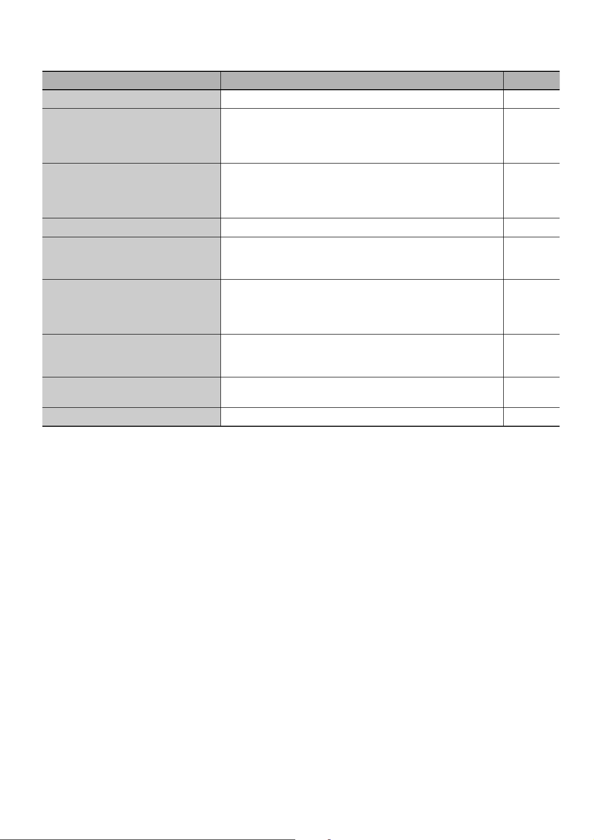
Symptom Probable cause and corrective action Page
Power is suddenly turned on or off . The power-on/off timer is activated. Deactivate the timer. 27
• For RGB input, adjust “DOT CLOCK” and “CLOCK PHASE” on the
The picture becomes blurred.
Color is abnormally bright or dark.
Color is poor or unstable. Select the correct color system. 23
The picture is cut or shifted toward
one side.
Menu does not appear or disappears
quickly.
Some items are not shown on the
menu.
“PLEASE ENTER PASS ID” appears
when trying to turn on the monitor.
main menu.
• If the connection cable used for RGB terminal is long, set “SYNC
TERM.” to “LOW.”
• Adjust the picture quality on “PICTURE SETTING” of the main
menu.
• If “TEMP. OVER” is displayed, follow the procedure described on
page 36.
• Input signals (scanning frequency, etc.) are not appropriate.
• Adjust the size and position properly.
When “INPUT B” of “INPUT CONFIGURATION” is set to
“COMPONENT” with a personal computer connected to the
RGB/COMPO. terminal, the menu operation is not available. Select
another input to operate the menu.
Items not available for the current input signal are not displayed.
Change the input or signal format. Some items are displayed only
when the corresponding optional input card is inserted.
The Power-on Lock is activated. Enter the password to turn on the
monitor, and then deactivate the Power-on Lock.
19
27
19
36
11
19
21
—
25, 30
•
•
•
Buttons on the main unit do not work. The Control Lock is activated. Deactivate it. 27
Pixel defects
LCDs use collections of fi ne points (“pixels”) to display images. While there is no problem with more than 99.99% of these
pixels, please understand that a very small number of pixels may not light, or may light all the time.
35
Page 36

Troubleshooting (cont.)
Self-diagnostic indication
When something abnormal occurs with the monitor, this function informs you of the condition of the monitor with the selfdiagnostic lamps, allowing for smooth service work.
123
Self-diagnostic lamps
Power lamp
“TEMP. OVER” appears here.
If the monitor screen turns off and the self-diagnostic
lamps light or fl ash
If the self-diagnostic lamps light or fl ash in red, check the following
before consulting the dealer where you purchased the monitor.
• If the self-diagnostic lamp 1 (upper) fl ashes, lamp 2 (middle)
lights, and lamp 3 (lower) fl ashes
This may be caused by the dusty intakes on the rear. If this
happens, switch off the main power using the POWER switch
(set to “‡ (off )”), unplug the AC power cord, then clean the
intakes by referring to the instruction on page 4.
After cleaning, switch on the monitor’s main power again. If
the self-diagnostic lamps do not go off , consult your dealer
immediately.
If the monitor screen dims a little and “TEMP. OVER”
appears (or fl ashes)
If “TEMP. OVER” appears or fl ashes at the right bottom of the
screen, check the following before consulting the dealer where
you purchased the monitor.
“TEMP. OVER” appears to warn you of internal heat buildup, which
is usually caused by accumulated dust around the intakes or by
improper installation. If the cause of the internal heat buildup is
eliminated, this indication disappears and the screen returns to
normal brightness.
• If “TEMP. OVER” fl ashes in yellow
This may be caused by the dusty intakes on the rear. If this
happens, switch off the main power using the POWER switch
(set to “‡ (off )”), unplug the AC power cord, then clean the
intakes by referring to the instruction on page 4.
– After cleaning, switch on the monitor’s main power again.
If “TEMP. OVER” still fl ashes, this problem may be caused by
improper installation or improper location of the monitor.
In this case, consult your dealer immediately to solve this
improper installation and to improve the circumstances
around the monitor.
• If “TEMP. OVER” appears in red
“TEMP. OVER” will be shown for about two minutes, the monitor
will shut off automatically, then the self-diagnostic lamps light in
red. If this happens, switch off the main power using the POWER
switch (set to “‡ (off )”), unplug the AC power cord, then consult
your dealer immediately.
If the trouble still persists, follow the procedure below:
1 Check which lamps are lit or fl ashing.
On the Self-diagnostic Report Sheet (below), check the box
next to “Lights” or “Flashes” of the corresponding lamp or
lamps.
• Only one lamp may light or fl ash, or all three lamps may do
so.
2 Switch off the POWER switch on the back of the
monitor.
3 Unplug the power cord.
4 Call your dealer and tell them which lamps are lit or
fl ashing. (Copy and fax the Self-diagnostic Report
Sheet below.)
NOTE
• If you switch on the main power immediately after switching it
off (or after recovering from a brief power interruption), the selfdiagnostic lamps may light (or fl ash), and no image may appear
on the screen. In this case, switch off the main power again, wait
for about 10 seconds, then switch it on again. If no self-diagnostic
lamps light or fl ash, you can operate and use the monitor as usual.
Self-diagnostic Report Sheet
Store name where you purchased the monitor
To
Model name: LCD DISPLAY MONITOR GM-H40L1G
The self-diagnostic lamps light or fl ash as listed on the following
table. Please give me immediate advice or service if necessary.
Self-diagnostic lamp
No. Lamp position Conditions
1 Upper
2Middle
3Lower
TEMP. OVER
Your Name
Telephone No.:
Address:
& Lights & Flashes
& Lights & Flashes
& Lights & Flashes
& Lights & Flashes
36
Page 37

Specifi cations
General
Model name GM-H40L1G
Frame color Metallic dark gray
Screen size Type 40 wide format
Aspect ratio 16:9 (Wide format)
LCD panel 40“ wide, active matrix TFT
13
Eff ective screen size (W x H, Diagonally) 885 mm x 498 mm (34
Number of pixels displayed 1 366 (H) x 768 (V)
Number of colors displayed 16.77 million (256 colors for each of RGB)
Viewing angle (TYP.) 170° (Horizontally), 170° (Vertically)
Brightness (TYP.) 400 cd/m
Contrast ratio (TYP.) 800:1
Response time less than 20 msec (Tr + Tf)
Weight 26.8 kg (59.0 lbs)
External dimensions (W x H x D) 986 mm x 595 mm x 123 mm (38
Power requirements AC 120 V, 50 Hz/60 Hz
Rated input current 2.4 A
Compatible signals See page 11.
Audio power output Internal: 1.7 W + 1.7 W (at impedance 8 Ω)
External: 6 Ω – 8 Ω, 2.2 W + 2.2 W (at impedance 6 Ω)
Speaker Ellipse (40 mm (1
Operating conditions Temperature: 0°C – 40°C (32°F – 104°F)
Relative humidity: 20% – 80% (non-condensation)
(Slightly variable depending on ambient conditions for installation.)
2
/16” x 19 9/16”), 1 015 mm (39 15/16”)
7
/8” x 23 1/2” x 4 7/8”)
5
/8”) x 70 mm (2 7/8”)) x 2, impedance 8 Ω
Input/output terminals
VIDEO IN A Video input BNC terminal x 1 1 V (p–p), 75 Ω
Y/C terminal x 1 Y: 1 V (p–p), 75 Ω
C (BURST): 0.286 V (p–p), 75 Ω (for NTSC)
0.3 V (p–p), 75 Ω (except for NTSC)
Video output BNC terminal x 1 1 V (p–p), 75 Ω
VIDEO IN B RGB/COMPONENT input D-sub 3-row 15-pin x 1 (RGB is compatible with DDC2B.)
Video signal G, Y: 1 V (p–p), 75 Ω (including sync)
B/CB, PR/CR: 0.7 V (p–p), 75 Ω
B, R, P
Horizontal sync (HD)/Composite sync (Cs) HD: 0.3 V (p–p) to 5 V (p–p), 1 kΩ (positive/negative
polarity)
Cs: 0.3 V (p–p) to 5 V (p–p), 1 kΩ (positive/negative
polarity)
Vertical sync (VD) VD: 1 V (p–p) to 5 V (p–p), 1 kΩ (positive/negative
polarity)
DVI input DVI-D terminal x 1 (Compatible with DDC2B)
AUDIO IN A Audio input Pin jack terminal x 2 (L/R) 500 mV (rms), high impedance
AUDIO IN B Audio input Stereo mini jack terminal x 1 500 mV (rms), high impedance
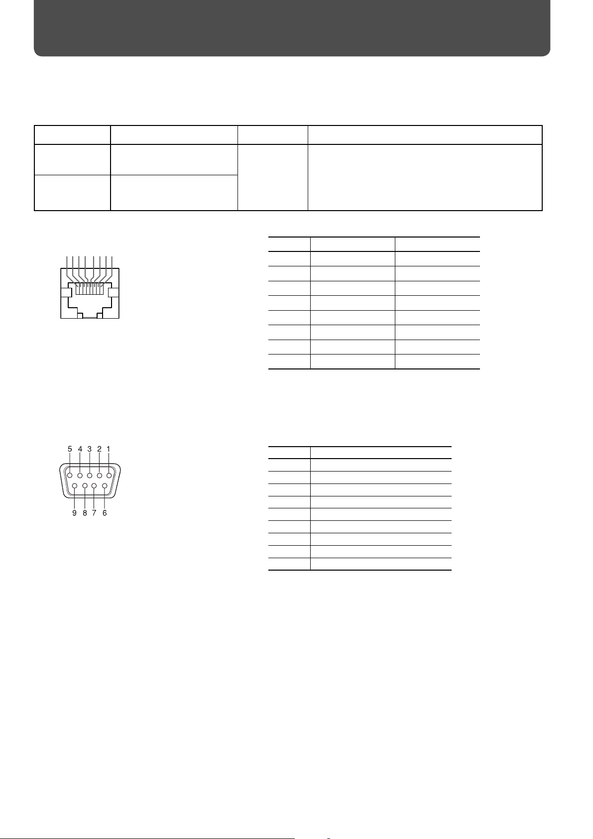
REMOTE RS-232C input D-sub 9-pin terminal x 1 (For RS-232C control)
RS-485 input RJ-45 pin terminal x 1 (For RS485, MAKE, and TRIGGER control)
RS-485 output RJ-45 pin terminal x 1 (For RS485 and IR OUT control)
AUDIO OUT MONITOR OUT Pin jack terminal x 2 (L/R) Output impedance 600 Ω
EXT. SPEAKER Speaker output terminal (L/R) Impedance 6 Ω to 8 Ω
37
Page 38

1
2
3
4
Specifi cations (cont.)
Dimensions
Unit: mm (inch)
Top view
Front view Side view Rear view
595 (23 1/2)
498 (19 9/16)
500.3 (19 3/4)
885 (34 13/16)
887.8 (35)
986 (38 7/8)
* Eff ective screen size
48 (2)
123 (4 7/8)
Screw hole for optional installation unit.
Screw size: 6 – M6, depth: 20 mm
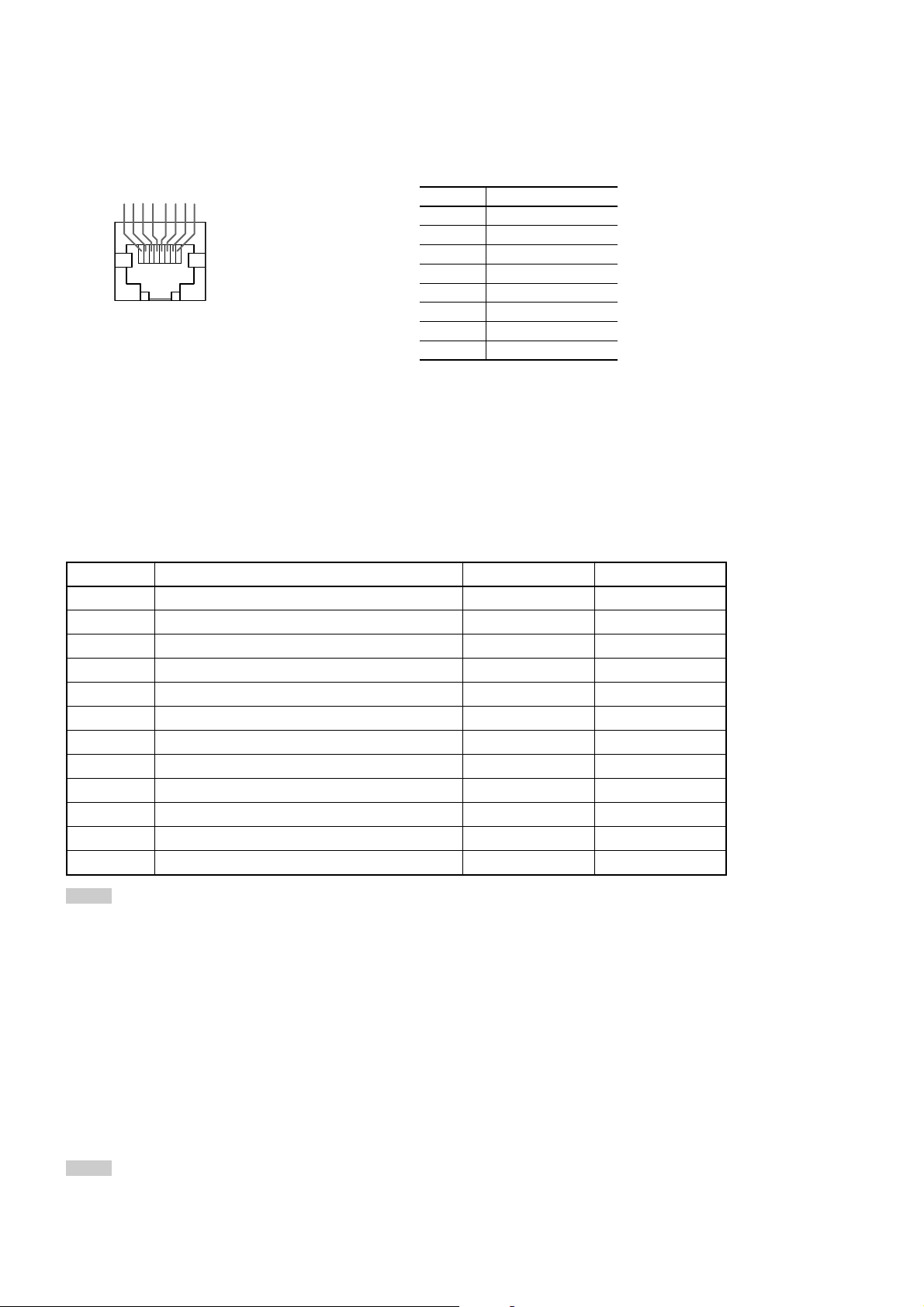
DVI-D input terminal
18
916
17 24
Pin No. Signal name Pin No. Signal name Pin No. Signal name
1 T.M.D.S Data 2– 9 T.M.D.S Data 1– 17 T.M.D.S Data 0–
2 T.M.D.S Data 2+ 10 T.M.D.S Data 1+ 18 T.M.D.S Data 0+
3 T.M.D.S Data 2/4 shield 11 T.M.D.S Data 1/3 shield 19 T.M.D.S Data 0/5 shield
4 NC 12 NC 20 NC
5 NC 13 NC 21 NC
6 DDC Clock 14 +5 V Power 22 T.M.D.S Clock shield
7 DDC Data 15 GND 23 T.M.D.S Clock+
8 NC 16 Hot Plug Detect 24 T.M.D.S Clock–
400
200
80
117.5
RGB/COMPONENT input terminal
Pin No. Signal name Pin No. Signal name
1 Red 9 +5V
2 Green 10 GND
3 Blue 11 GND
4 N/C 12 DDC Data
5 GND 13 HD/Cs
6 GND 14 VD
7 GND 15 DDC Clock
8 GND
Y/C IN terminal
Pin No. Signal name
1 GND (Y)
2 GND (C)
3 Y
4 C
External
GND
38
Page 39

Options (not supplied)
Stand Unit TS-CL03SG
Wall Mounting Unit TS-CV20WG
• Consult your dealer to see if other options are available.
Notice on transportation
This monitor is precision equipment and needs dedicated packing material for transportation.
Never use any packing material supplied from sources other than JVC or JVC-authorized dealers.
• For easy understanding, pictures and illustrations are shown by being emphasized, omitted or composed, and may be
more or less diff erent from actual products.
• Design and specifi cations are subject to change without notice.
• IBM and IBM PC are registered trademarks of International Business Machines Corporation. Macintosh is registered
trademarks of Apple Computer, Inc.
All other product names mentioned herein are used for identifi cation purposes only, and may be the trademarks or
registered trademarks of their respective companies.
39
Page 40

GM-H40L1G LCD DISPLAY MONITOR
© 2005 Victor Company of Japan, Limited
1005MKH-MW-VP
 Loading...