

Page 1
DIGITAL STILL CAMERA
GC-S1
Please visit our CyberCam Homepage on
the World Wide Web and answer our
Consumer Survey (in English only):
ENGLISH
http://www.jvc-victor.co.jp/index-e.html
STILL CAMERA
INSTRUCTIONS
For Customer Use:
Enter below the Model No. and Serial
No. which is located on the bottom of
cabinet. Retain this information for
future reference.
Model No.
Serial No.
LYT0142-001B
Page 2
2 EN
Dear Customer,
Thank you for purchasing the Digital Still
Camera. Before use, please read the safety
information and precautions contained in the
following pages to ensure safe use of your new
Digital Still Camera.
Using This Instruction Manual
• All major sections and subsections are listed in the
Table Of Contents (
• Notes appear after most subsections. Be sure to read
these as well.
• Basic and advanced features/operation are separated
for easier reference.
It is recommended that you . . .
..... refer to “CONTROLS, CONNECTORS AND
INDICATORS” (
familiarize yourself with button locations, etc.
before use.
..... read thoroughly the Safety Precautions and Safety
Instructions that follow. They contain extremely
important information regarding the safe use of
your new Digital Still Camera.
You are recommended to carefully read the
cautions on pages 65 – 67 before use.
Z pg. 8, 9).
Z pgs. 56 – 61) and
SAFETY
PRECAUTIONS
The AA-V33U AC Power Adapter should be
used with:
AC 120 V`, 60 Hz in the USA and Canada,
AC 110 – 240 V`, 50/60 Hz in other countries.
CAUTION (applies to the AA-V33U)
TO PREVENT ELECTRIC SHOCK MATCH WIDE
BLADE OF PLUG TO WIDE SLOT, FULLY
INSERT.
ATTENTION (s’applique à l’AA-V33U)
POUR ÉVITER LES CHOCS ÉLECTRIQUES,
INTRODUIRE LA LAME LA PLUS LARGE DE LA
FICHE DANS LA BORNE CORRESPONDANTE
DE LA PRISE ET POUSSER JUSQU’AU FOND.
NOTES:
●
The rating plate (serial number plate) and
safety caution are on the bottom and/or the
back of the main unit.
●
The rating plate (serial number plate) of the
AC Power Adapter is on its bottom.
CAUTION:
CAUTION
RISK OF ELECTRIC SHOCK
DO NOT OPEN
CAUTION: TO REDUCE THE RISK OF ELECTRIC SHOCK.
DO NOT REMOVE COVER (OR BACK).
REFER SERVICING TO QUALIFIED SERVICE PERSONNEL.
NO USER-SERVICEABLE PARTS INSIDE.
The lightning flash with arrowhead symbol, within an
equilateral triangle, is intended to alert the user to the
presence of uninsulated "dangerous voltage" within the
product's enclosure that may be of sufficient magnitude
to constitute a risk of electric shock to persons.
The exclamation point within an equilateral triangle is
intended to alert the user to the presence of important
operating and maintenance (servicing) instructions in
the literature accompanying the appliance.
WARNING:
TO PREVENT FIRE OR SHOCK
HAZARD, DO NOT EXPOSE
THIS UNIT TO RAIN OR
MOISTURE.
To avoid electric shock or damage to the unit,
first firmly insert the small end of the power
cord into the AC Power Adapter until it is no
longer wobbly, and then plug the larger end of
the power cord into an AC outlet.
This camera is designed to be used with NTSCtype color television signals. It cannot be used
for playback with a television of a different
standard. However, shooting and LCD monitor
playback are possible anywhere.
Page 3

IMPORTANT PRODUCT
SAFETY INSTRUCTIONS
Electrical energy can perform many useful functions. But improper use can result in potential
electrical shock or fire hazards. This product has
been engineered and manufactured to assure your
personal safety. In order not to defeat the built-in
safeguards, observe the following basic rules for its
installation, use and servicing.
ATTENTION:
Follow and obey all warnings and instructions
marked on your product and its operating instructions. For your safety, please read all the safety and
operating instructions before you operate this
product and keep this manual for future reference.
INSTALLATION
1. Grounding or Polarization
(A) Your product may be equipped with a polarized
alternating-current line plug (a plug having one
blade wider than the other). This plug will fit into
the power outlet only one way. This is a safety
feature.
If you are unable to insert the plug fully into the
outlet, try reversing the plug. If the plug should still
fail to fit, contact your electrician to replace your
obsolete outlet. Do not defeat the safety purpose of
the polarized plug.
(B) Your product may be equipped with a 3-wire
grounding-type plug, a plug having a third
(grounding) pin. This plug will only fit into a
grounding-type power outlet. This is a safety
feature.
If you are unable to insert the plug into the outlet,
contact your electrician to replace your obsolete
outlet. Do not defeat the safety purpose of the
grounding-type plug.
2. Power Sources
Operate your product only from the type of power
source indicated on the marking label. If you are not
sure of the type of power supply to your home, consult
your product dealer or local power company. If your
product is intended to operate from battery power, or
other sources, refer to the operating instructions.
3. Overloading
Do not overload wall outlets, extension cords, or
integral convenience receptacles as this can result in a
risk of fire or electric shock.
4. Power Cord Protection
Power supply cords should be routed so that they are
not likely to be walked on or pinched by items placed
upon or against them, paying particular attention to
cords at plugs, convenience receptacles, and the point
where they exit from the product.
EN 3
5. Ventilation
Slots and openings in the cabinet are provided for
ventilation. To ensure reliable operation of the product
and to protect it from overheating, these openings must
not be blocked or covered.
•Do not block the openings by placing the product on
a bed, sofa, rug or other similar surface.
•Do not place the product in a built-in installation
such as a bookcase or rack unless proper ventilation
is provided or the manufacturer’s instructions have
been adhered to.
6. Wall or Ceiling Mounting
The product should be mounted to a wall or ceiling
only as recommended by the manufacturer.
ANTENNA INSTALLATION
INSTRUCTIONS
1. Outdoor Antenna Grounding
If an outside antenna or cable system is connected to
the product, be sure the antenna or cable system is
grounded so as to provide some protection against
voltage surges and built-up static charges. Article 810
of the National Electrical Code, ANSI/NFPA 70,
provides information with regard to proper grounding
of the mast and supporting structure, grounding of the
lead-in wire to an antenna discharge unit, size of
grounding conductors, location of antenna discharge
unit, connection to grounding electrodes, and
requirements for the grounding electrode.
2. Lightning
For added protection for this product during a lightning
storm, or when it is left unattended and unused for long
periods of time, unplug it from the wall outlet and
disconnect the antenna or cable system. This will
prevent damage to the product due to lightning and
power-line surges.
3. Power Lines
An outside antenna system should not be located in the
vicinity of overhead power lines or other electric light
or power circuits, or where it can fall into such power
lines or circuits. When installing an outside antenna
system, extreme care should be taken to keep from
touching such power lines or circuits as contact with
them might be fatal.
EXAMPLE OF ANTENNA GROUNDING AS PER
NATIONAL ELECTRICAL CODE, ANSI/NFPA 70
ANTENNA
LEAD IN WIRE
GROUND CLAMP
ANTENNA
DISCHARGE UNIT
(NEC SECTION
ELECTRIC SERVICE
EQUIPMENT
POWER SERVICE GROUNDING ELECTRODE SYSTEM
(NEC ART 250. PART H)
NEC – NATIONAL ELECTRICAL CODE
810-20)
GROUNDING CONDUCTORS
(NEC SECTION 810-21)
GROUND CLAMPS
Page 4

4 EN
USE
1. Accessories
To avoid personal injury:
•Do not place this product on an unstable cart,
stand, tripod, bracket or table. It may fall, causing
serious injury to a child or adult, and serious
damage to the product.
•Use only with a cart, stand, tripod, bracket, or
table recommended by the manufacturer or sold
with the product.
•Use a mounting accessory recommended by the
manufacturer and follow the manufacturer’s
instructions for any mounting of the product.
•Do not try to roll a cart with small casters across
thresholds or deep-pile carpets.
2. Product and Cart Combination
A product and cart combination should be moved
with care. Quick stops, excessive force, and uneven
surfaces may cause the product and cart combination to overturn.
3. Water and Moisture
Do not use this product
near water—for example,
near a bath tub, wash
bowl, kitchen sink or
laundry tub, in a wet
basement, or near a
swimming pool and the
like.
4. Object and Liquid Entry
Never push objects of any kind into this product
through openings as they may touch dangerous
voltage points or short-out parts that could result in
a fire or electric shock. Never spill liquid of any
kind on the product.
5. Attachments
Do not use attachments not recommended by the
manufacturer of this product as they may cause
hazards.
6. Cleaning
Unplug this product from the wall outlet before
cleaning. Do not use liquid cleaners or aerosol
cleaners. Use a damp cloth for cleaning.
7. Heat
The product should be situated away from heat
sources such as radiators, heat registers, stoves, or
other products (including amplifiers) that produce
heat.
PORTABLE CART WARNING
(Symbol provided by RETAC)
SERVICING
1. Servicing
If your product is not operating correctly or exhibits
a marked change in performance and you are
unable to restore normal operation by following the
detailed procedure in its operating instructions, do
not attempt to service it yourself as opening or
removing covers may expose you to dangerous
voltage or other hazards. Refer all servicing to
qualified service personnel.
2. Damage Requiring Service
Unplug this product from the wall outlet and refer
servicing to qualified service personnel under the
following conditions:
a. When the power supply cord or plug is damaged.
b. If liquid has been spilled, or objects have fallen
into the product.
c. If the product has been exposed to rain or water.
d. If the product does not operate normally by
following the operating instructions. Adjust only
those controls that are covered by the operating
instructions as an improper adjustment of other
controls may result in damage and will often
require extensive work by a qualified technician
to restore the product to its normal operation.
e. If the product has been dropped or damaged in
any way.
f. When the product exhibits a distinct change in
performance—this indicates a need for service.
3. Replacement Parts
When replacement parts are required, be sure the
service technician has used replacement parts
specified by the manufacturer or have the same
characteristics as the original part. Unauthorized
substitutions may result in fire, electric shock or
other hazards.
4. Safety Check
Upon completion of any service or repairs to this
product, ask the service technician to perform safety
checks to determine that the product is in safe
operating condition.
Page 5
QUICK START
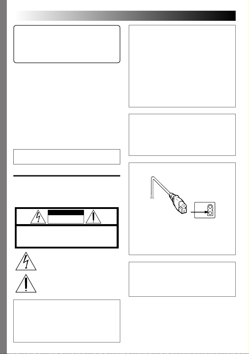
1
Four AA (LR6)-size
alkaline batteries
2
BATTERY cover
Load batteries. (Z pg. 10)
Slide the BATTERY cover slightly to open.
1
Insert four AA (LR6)-size batteries as indicated
2
by the orientation marking inside the cover.
Power Dial
Lock button
OFF
Y
A
P
L
Turn the power on. (Z pg. 16)
Turn the Power Dial to “A”.
1
•Turn while holding the Lock Button depressed.
EN 5
CONTINUED ON NEXT PAGE
Page 6
6 EN
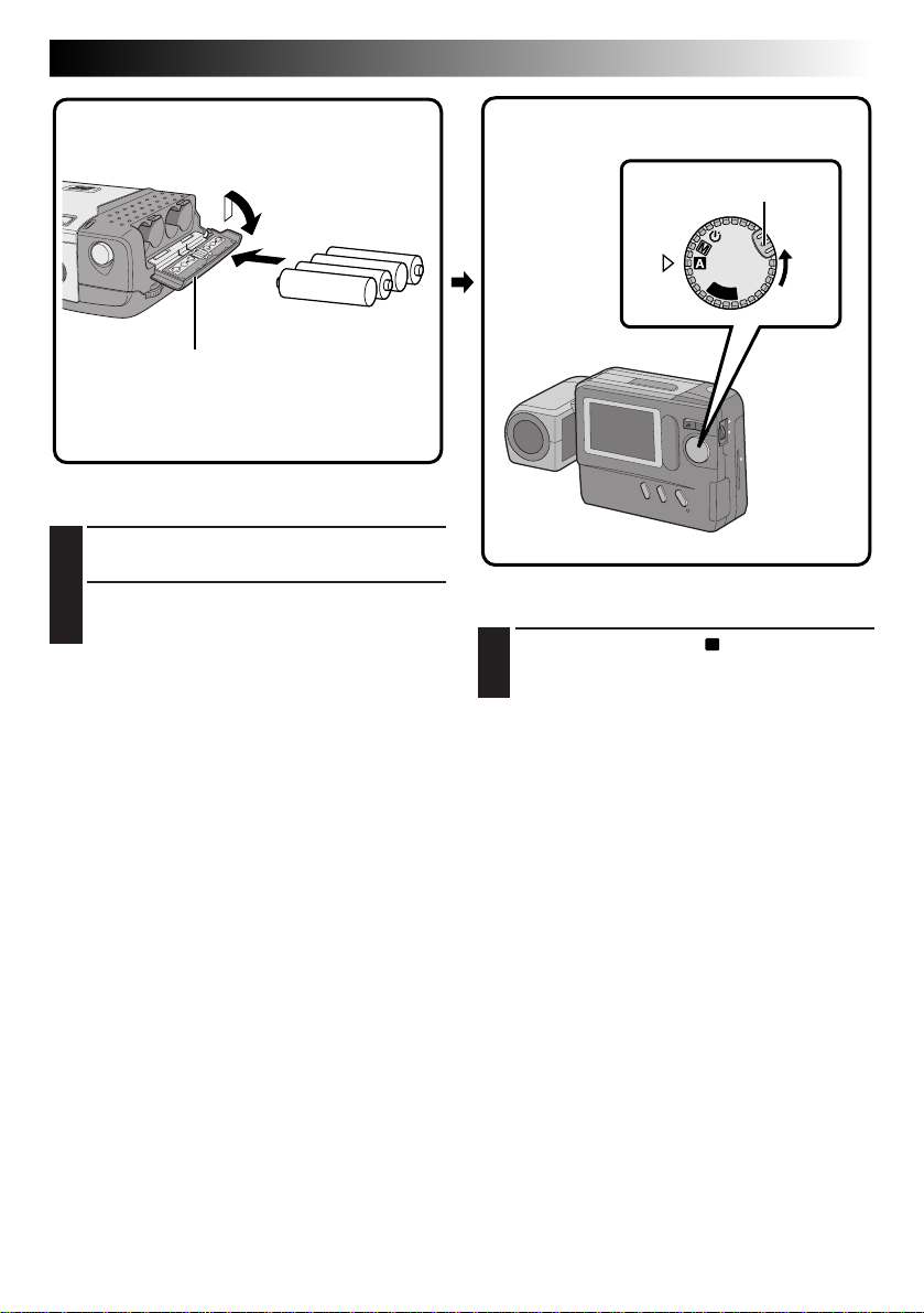
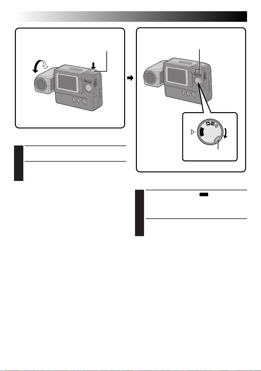
1
190°
Shutter Release Button
2
QUICK START
Zoom Button
2
(cont.)
Shoot an image. (Z pg. 18)
Tilt the lens and point it at the subject.
1
Press the Shutter Release Button.
2
•A still image is stored in the camera's
memory.
1
Power Dial
OFF
Y
A
L
P
Lock button
Play an image. (Z pg. 33)
Turn the Power Dial to “
1
•Turn while holding the Lock Button depressed.
•A still image stored in memory appears.
Select an image with the Zoom Button.
PLAY
”.
2
Page 7
MAJOR FEATURES
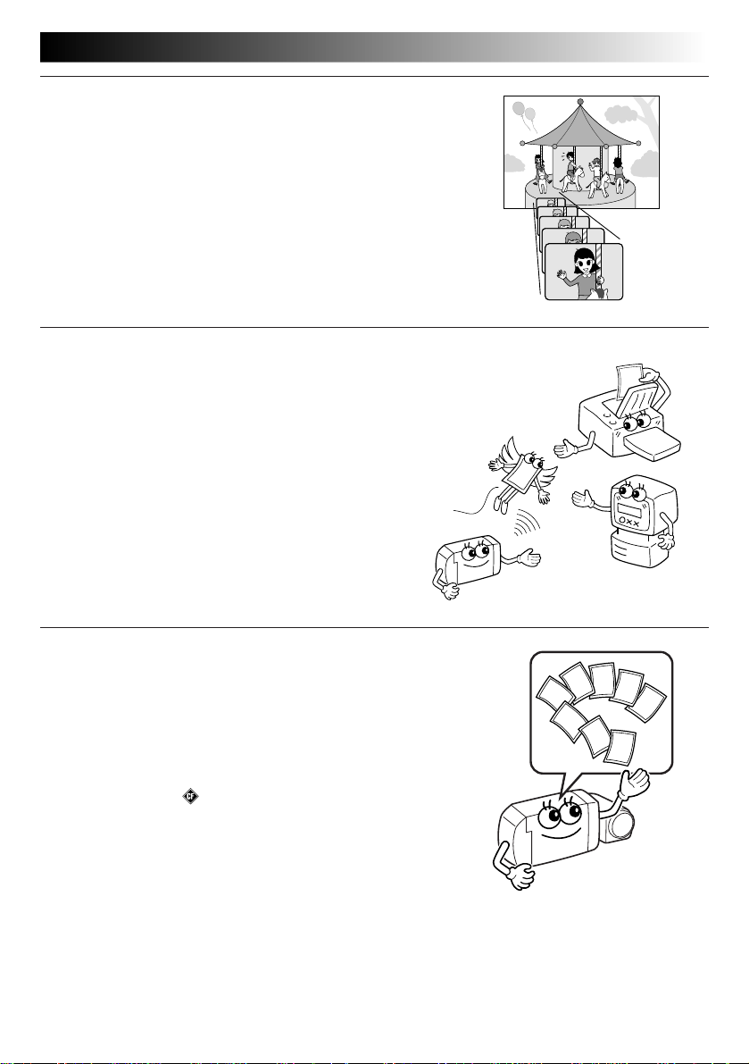
10X Zoom for Magnifying Distant Subjects
When a subject is located too far away to be approached, its image
can be enlarged using 10X zoom.
An image shot by zooming has much higher quality than a nonzoomed image enlarged using image processing software on a PC.
Cordless Image Transfer Using Infrared Communication (IrTran-P Compatible)
IrTran-P is the most advanced infrared communication protocol
available today.
Images can be transferred to another piece of equipment without
using a cable, provided that it is compatible with the IrTran-P
standard.
EN 7
Compact Flash Card for Shooting More Images
The Compact Flash card makes it possible to shoot and store
images in addition to those that can be stored in the built-in
memory.
The extra available images mean you don’t have to worry about
missing great shots. Also, by using several Compact Flash cards,
you can make a library of images archived by category, or you can
create personal archives for each person when a single camera is
shared by several users.
COMPACTFLASH and are trademarks of SanDisk Corporation,
registered in the U.S.A. and other countries.
Page 8

8 EN
CONTENTS
SAFETY PRECAUTIONS
QUICK START
MAJOR FEATURES
CONTENTS
GETTING STARTED
Loading Batterirs ............................................................................. 10
Unloading Batteries .......................................................................... 10
Household Power Supply .................................................................... 11
Date/Time Setting ........................................................................... 12
BASIC OPERATION
Lens Adjustment .............................................................................. 14
Shutter Release Button ...................................................................... 14
Brightness Control............................................................................ 15
Shooting Mode Selection .................................................................... 16
Picture Mode Selection ...................................................................... 17
Simple Shooting (Full Auto Shooting) ...................................................... 18
Camera Setup Check ......................................................................... 19
Zoom Shooting................................................................................ 20
Self-Timer Shooting .......................................................................... 21
Flash Shooting ................................................................................ 22
Exposure Control ............................................................................. 23
MANUAL SHOOTING
White Balance Control ....................................................................... 24
Adjusting the White Balance ............................................................. 24
Adjusting the White Balance Manually (M.W.B.) ..................................... 25
Shutter Speeds Selection .................................................................... 26
Selecting the Shutter Speed.............................................................. 26
Shutter Speeds and Effects .............................................................. 27
Manual Focusing .............................................................................. 28
View Mode Selection ........................................................................ 29
Power Save Mode............................................................................ 30
Flash Adjustment ............................................................................. 31
PLAYBACK
Playback Through a TV Monitor or VCR................................................... 32
Normal Playback ............................................................................. 33
Auto Playback ................................................................................ 33
INDEX Screen ................................................................................. 34
Index Playback ............................................................................... 35
Protecting Images ............................................................................ 36
Deleting Images .............................................................................. 38
2
5
7
8
10
14
24
32
Page 9
Applying Sepia/Black-and-White Effects ................................................. 40
Magnifying the Playback Image (Zoom) .................................................. 41
Types of Frames .............................................................................. 42
Framing an Image ............................................................................ 43
Multi-Image Screen .......................................................................... 44
ADVANCED OPERATION
Compact Flash Card Operation.............................................................. 46
Installing a Compact Flash Card ......................................................... 46
Removing a Compact Flash Card ........................................................ 46
Initializing the Storage Media .............................................................. 47
Storing Images in a Compact Flash Card .................................................. 48
Playing Back Images Stored in a Compact Flash Card ................................... 48
Copying Images Between the Built-in Memory and a Compact Flash ................. 49
Image Copy Using Infrared Communication [IrTran-P] .................................. 52
PC Connection Operation .................................................................... 54
CONTROLS, CONNECTORS AND INDICATORS
TROUBLESHOOTING
DISPLAY AND MESSAGES
CAUTIONS
MAJOR SPECIFICATIONS
INDEX
FOR SERVICING (Only in U.S.A.)
WARRANTY (Only in U.S.A.)
EN 9
46
56
62
64
65
68
69
70
71
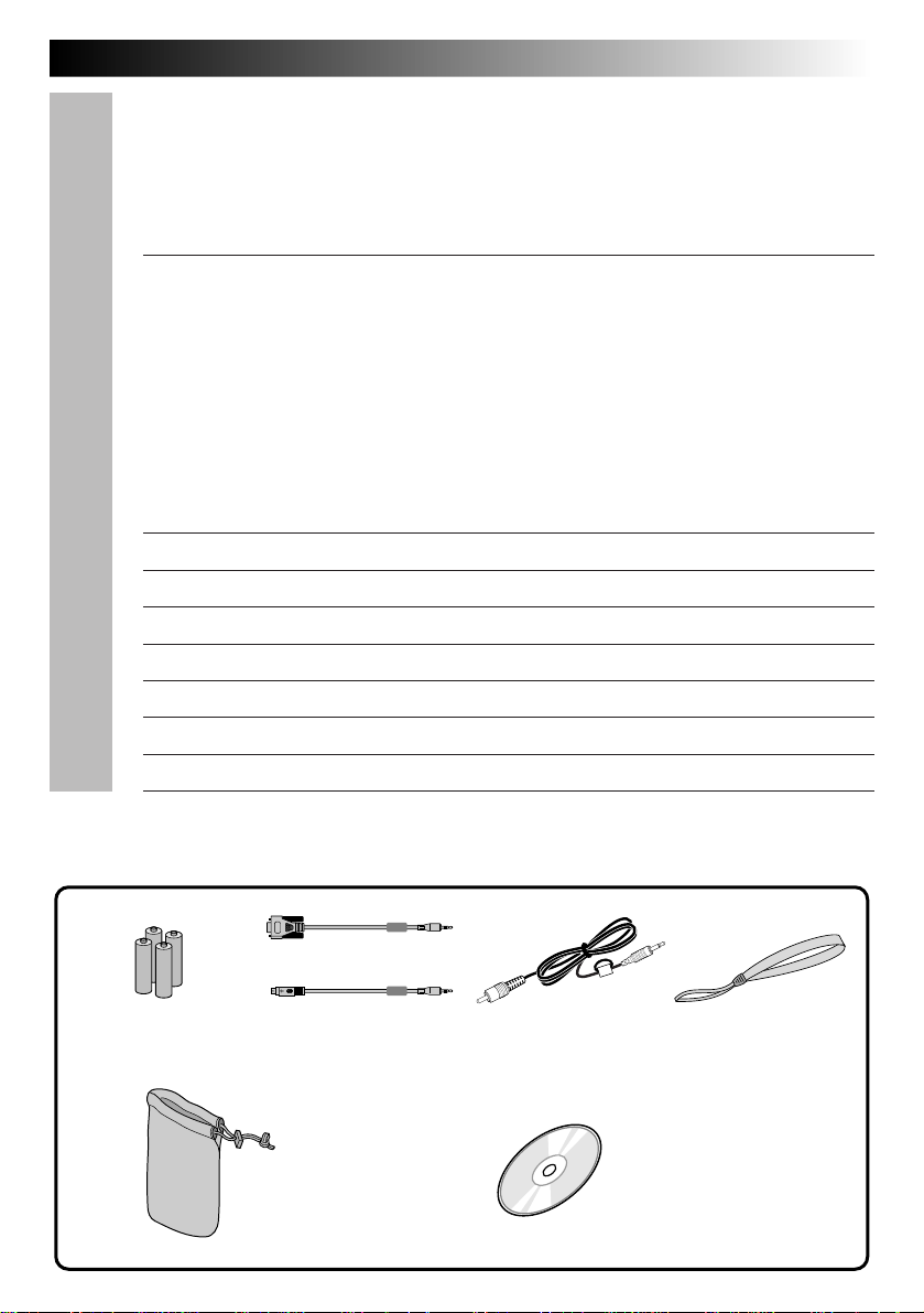
PROVIDED ACCESSORIES
x 1 for Windows
AA (LR6)-size
alkaline battery x 4
x 1 for Macintosh
PC connection cable
Soft case
®
PC
®
Video cable Hand strap
CD-ROM
• Picture Navigator
• MGI PhotoSuite SE
Page 10
10 EN
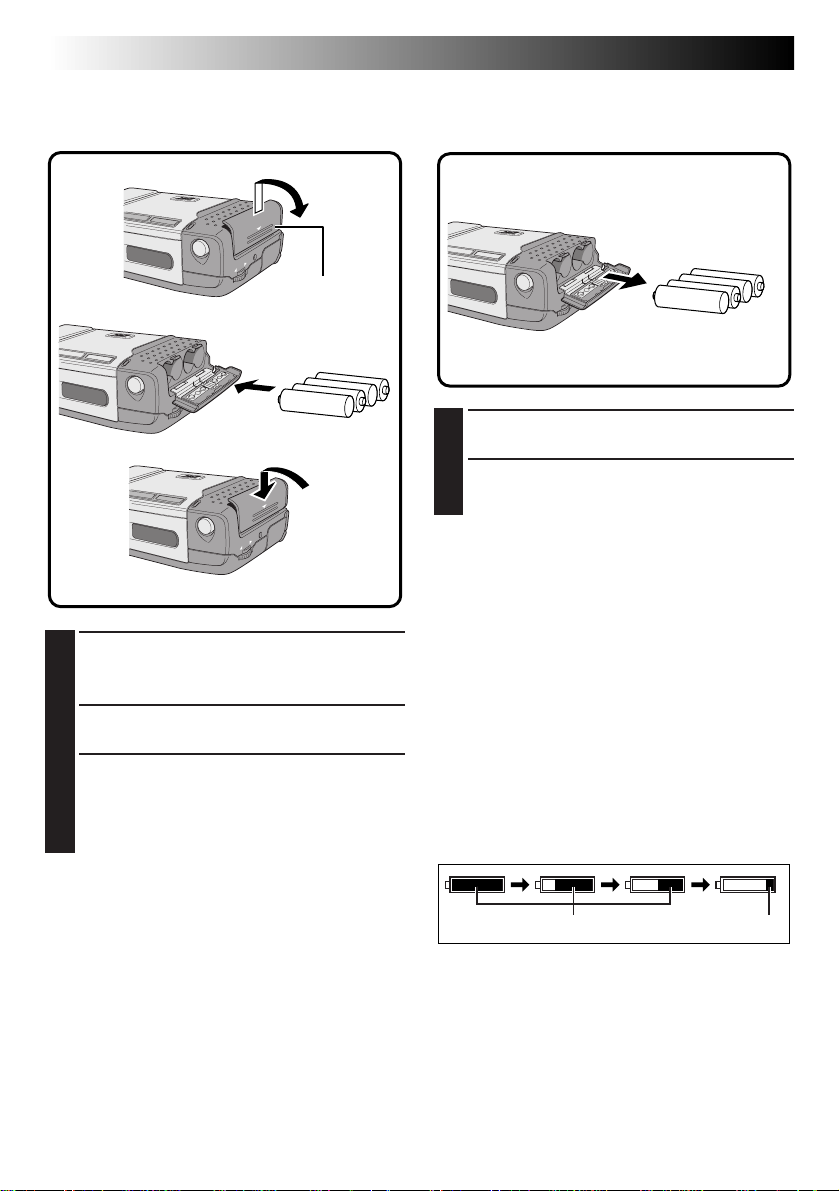
Loading Batteries
Use AA (LR6)-size dry cell batteries.
1
GETTING STARTED
Unloading Batteries
2
BATTERY
Cover
3
Slide the battery cover (BATTERY) slightly to
1
open.
•The battery cover opens.
Insert batteries as indicated by the orientation
2
marking inside the battery cover.
Close the battery cover and slide it back.
3
•The battery cover is locked in the closed
position.
•Make sure the battery cover is closed
securely.
Open the battery cover by performing step 1
1
of “Loading Batteries” to the left.
Take out batteries by tilting the camera
2
slightly.
NOTES:
●
Do not use manganese batteries as they do not
have sufficient energy to power this camera.
●
If the batteries are not used for an extended
period, remove them from the camera to avoid
battery leakage, which can cause malfunctions to
occur.
●
Battery life varies depending on the temperature
of the location where the battery is being used.
●
Battery capacity varies considerably depending
on the battery's brand.
●
Since batteries become very hot after they are
exhausted, be careful when replacing them with
new ones.
●
Replace the batteries when the battery power
remaining indicator displays the red mark.
NOTES:
●
Commercially-available AA (LR6)-size nickelcadmium (Ni-Cd) or nickel-metal hydride (NiMH) batteries can also be used. Ni-Cd or Ni-MH
batteries are more economical because they can
be recharged and used repeatedly. Be sure to read
their instructions.
●
Inserting batteries in the incorrect direction may
cause them to leak.
green
red
Page 11
EN 11
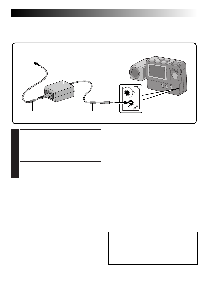
Household Power Supply
When using the camera indoors, it is more convenient and economical to power it from a household AC
power outlet using an AC power adapter (optional).
To AC outlet
3
AA-V33 AC power
adapter (optional)
1
Core filter Core filter
Connect the Power Cord to the AC Power
1
Adapter.
•Make sure connections are secure.
Connect the DC Cord to the DC Input
2
Connector of the Digital Still Camera.
Connect the Power Cord to an AC outlet.
3
•After use, unplug the Power Cord from the
AC outlet.
2
VIDEO OUT
DC-IN
NOTES:
●
The optional AA-V33 AC Power Adapter features
automatic voltage selection in the AC range from
110 V to 240 V.
●
Make sure the Power Cord is securely connected
to the AC Power Adapter.
●
When using the AC Power Adapter, use only the
Power Cord provided with the AC Power Adapter.
Use of any other cord may result in shock or fire.
●
Connect the Power Cord to the AC Power Adapter
before connecting it to an AC outlet. If you plug it
into an outlet first, and the Adapter’s terminals
come in contact with a metal surface or object,
short circuit or fire may result.
●
Vibration noise can sometimes be heard coming
from the inside of the AC Power Adapter. This is
normal.
●
The AC Power Adapter processes electricity
internally, and will become warm during use. This
is normal. Make sure to use the AC Power
Adapter in well-ventilated areas only.
ATTENTION:
Before detaching the power source, make
sure that the camera’s power is turned off.
Failure to do so may cause the camera’s
built-in memory to be corrupted.
Page 12
12 EN
GETTING STARTED
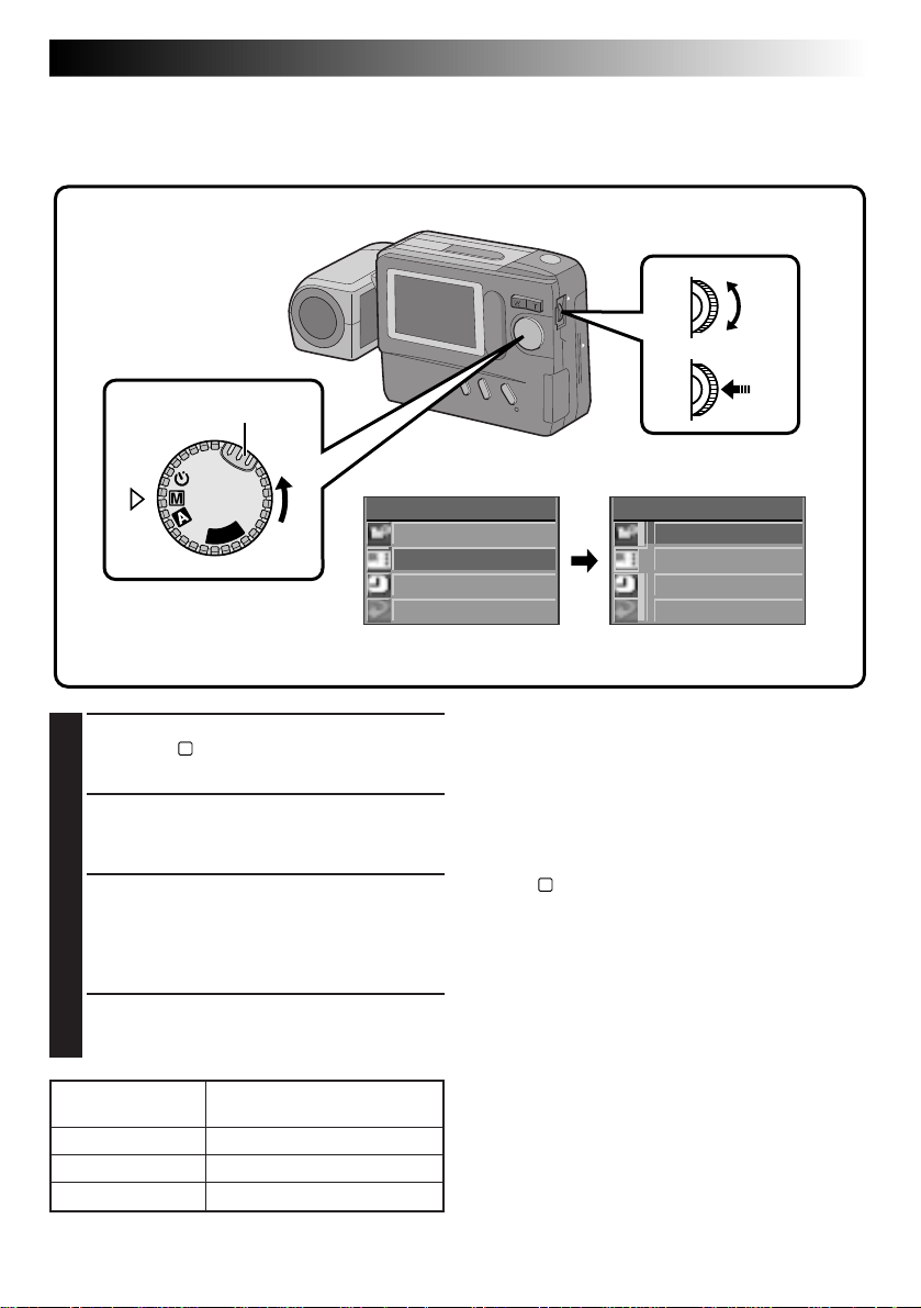
Date/Time Setting
By setting the date and time, date/time data can be viewed along with your pictures.
Date/time data is also convenient for categorizing pictures later.
Power Dial
Lock Buton
P
L
A
Y
OFF
(cont.)
MENU Jog Dial
LCD monitor
CAMERA MENU
CAMERA
P I CTURE MODE
SYSTEM
EX I T
CAMERA MENU Screen SYSTEM Setup Screen
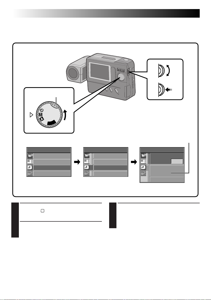
Turn the Power Dial, while pressing its Lock
1
Button, to “M” and push the MENU Jog Dial.
•The CAMERA MENU Screen appears.
Rotate the MENU Jog Dial to select “SYSTEM”
2
and push it.
•The SYSTEM Setup Screen appears.
SYSTEM
POWER SAVE
FLASH ADJ .
DATE / T IME
EX I T
Rotate the MENU Jog Dial to select “DATE/
3
TIME” and push it.
•The DATE/TIME Setup Screen appears.
•If you wish to set only the time without
12-hour indication with AM or PM
DATE / T IME
DATE
DEC 27 . 1 9 98
T IME
A M 9 : 30
EX I T
DATE/TIME Setup Screen
changing the date, go to step 5.
Page 13

Set the values for the date.
4
1. Rotate the MENU Jog Dial to select the item
in the “DATE” section you wish to set and
push it.
•The item color changes to indicate that
setting is possible.
2. Rotate the MENU Jog Dial until the correct
setting appears and push it.
•Repeat this procedure until you are
satisfied with the date settings.
• If you wish to set only the date without
changing the time, go to step 6.
Set the values for the time.
5
1. Rotate the MENU Jog Dial to select the item
in the “TIME” section you wish to set and
push it.
•The item color changes to indicate that
setting is possible.
2. Rotate the MENU Jog Dial until the correct
setting appears and push it.
•When the MENU Jog Dial is pushed after
the minutes are set, “EXIT” is selected and
clock operation starts from 0 seconds.
•Repeat this procedure until you are
satisfied with the time settings.
Rotate the MENU Jog Dial to select “EXIT”
6
and push it 3 times.
•The shooting screen reappears and the clock
starts functioning.
EN 13
NOTES:
●
The date/time setting is backed up by a built-in
rechargeable clock battery. Connect the camera
to an AC outlet using the AC power adapter for
over 24 hours to charge the clock battery.
●
The clock will continue to advance except while
the minutes are being set. When the minutes are
set and the MENU Jog Dial is pushed, the seconds
are reset to “0” and clock operation starts.
●
Although the date/time which you have set is
stored in the camera’s built-in memory, the date/
time display will not be combined with the
pictures you shoot.
Page 14
14 EN
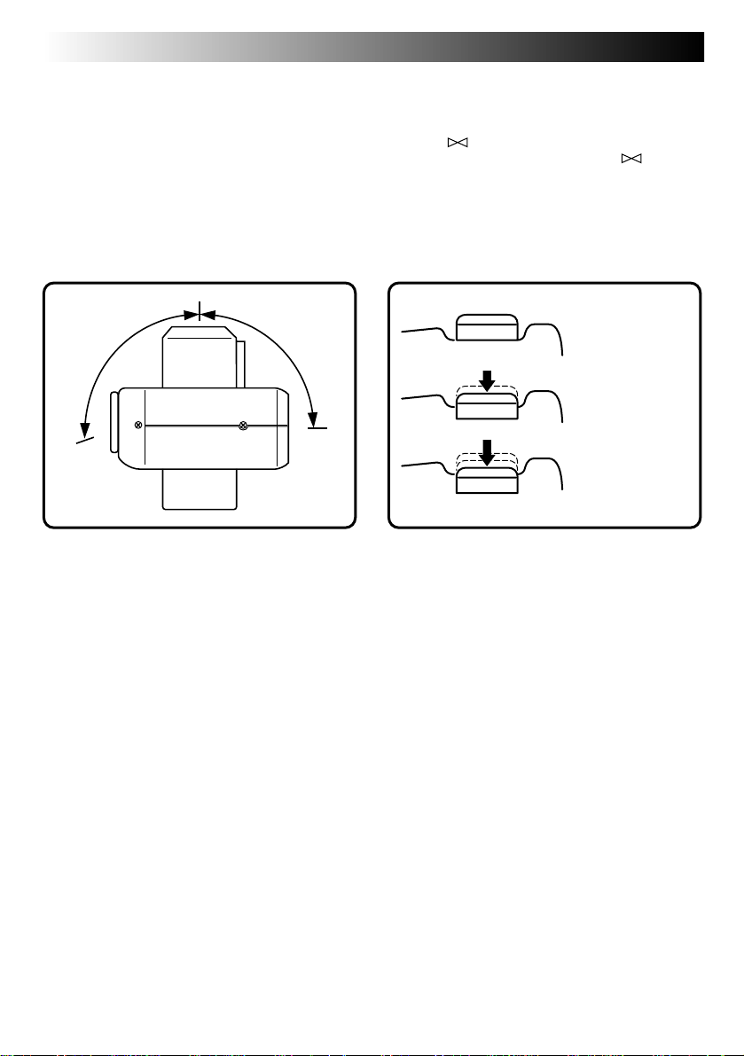
Lens Adjustment
To obtain the most stable position for shooting
while viewing the LCD monitor, hold the lens so
that it forms an angle of 45 degrees in relation to
the camera body.
The lens tilts up to 100 degrees forward and 90°
backward. You can photograph yourself, while
viewing your own image on the LCD monitor (SelfRecording), by tilting the lens 90 degrees backward
and taking your picture. This can be used for things
such as keeping a photo diary.
100° 90°
BASIC OPERATION
Shutter Release Button
The Shutter Release Button of the camera has two
steps. At the first step, when the button is pressed
halfway, “ ” is displayed and the camera
automatically focuses on the subject. “ ”
disappears once the subject has been brought into
focus.
The operation of pressing the Shutter Release Button
to the first step is called a “half-press”. From the
“half-pressed” position, press the button all the way
to the second step.
Unpressed
position
Half-pressed
position
Fully-pressed
position
NOTES:
●
Do not press the Shutter Release Button with your
finger raised over the button or do not press it
with too strong a force, as this may disrupt the
horizontal positioning of the image or cause
blurring. When shooting, always half-press the
button before pressing it fully to the second step.
●
If focusing is performed by pressing the Shutter
Release Button frequently during auto focus, the
period between when the Shutter Release Button
is pressed and when the shutter is released will be
shortened.
●
While the camera is performing auto focusing
with the button half-pressed, the displayed image
may freeze temporarily. This is not a malfunction.
●
When the Shutter Release Button is released from
the half-pressed position and half-pressed again,
the camera performs auto focusing again.
Page 15
EN 15
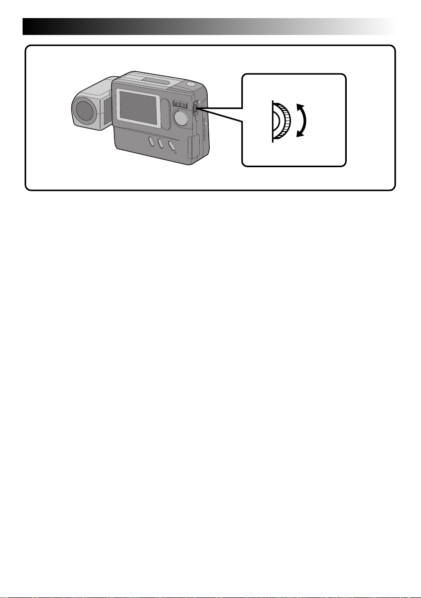
BRIGHT Dial (MENU Jog Dial)
To darken the image
To brighten the image
Brightness Control
You can adjust the brightness of the LCD monitor by rotating the BRIGHT dial, except during manual
focusing or menu adjustment.
To darken the image . . .
Rotate the BRIGHT dial upward.
To brighten the image . . .
Rotate the BRIGHT dial downward.
Page 16
16 EN
BASIC OPERATION
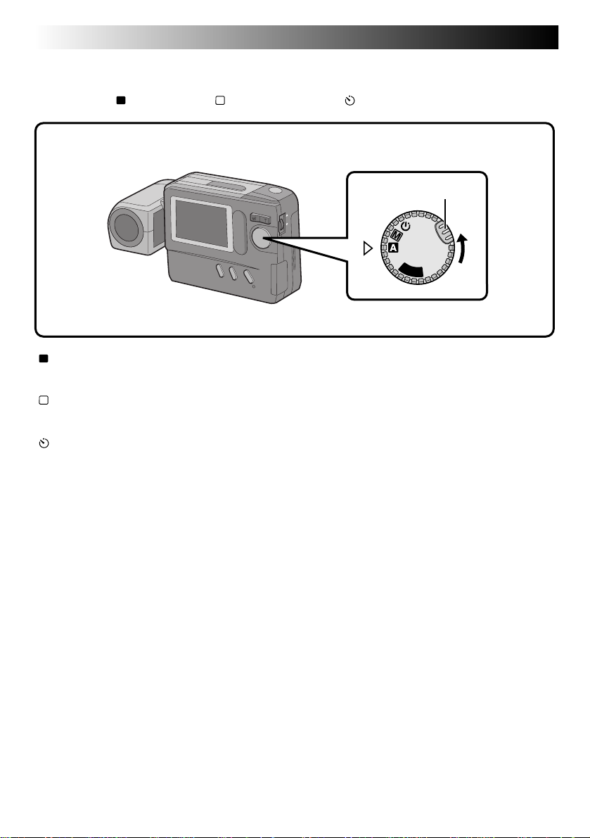
Shooting Mode Selection
Turning the Power Dial allows you to select the appropriate shooting mode from among the following:
Full Auto mode ( A ), Manual mode ( M ) and Self-Timer mode ( ).
Power Dial
Lock Button
OFF
Y
A
P
L
“
A
” : Full Auto mode
The camera will automatically control all items including exposure, shutter speed, focusing and
white balance.
“
M
” : Manual mode
Exposure, shutter speed, focusing and white balance can be controlled manually according to the
shooting conditions.
“
” : Self-Timer mode
A 15-second self-timer can be used.
(cont.)
Page 17
EN 17
Pictrue Mode Selection
The Picture Quality mode can be selected to best match your needs. Three Picture Quality modes are
available: FINE, STD (standard) and ECONOMY (in order of quality).
MENU Jog Dial
Power Dial
Lock Button
LCD monitor
P
L
A
Y
OFF
Turn the Power Dial, while pressing its Lock
1
Button, to “M” and push the MENU Jog Dial.
•The CAMERA MENU Screen appears.
Rotate the MENU Jog Dial to select “PICTURE
2
MODE” and push it.
•The PICTURE MODE Screen appears.
Rotate the MENU Jog Dial to select the
3
“FINE”, “STD” or “ECONOMY” Picture
Quality mode and push it.
•The Picture Quality mode is set, and the
CAMERA MENU Screen appears.
Push the MENU Jog Dial.
4
•The shooting screen reappears.
PICTURE QUALITY
MODE
FINE
STANDARD (STD)
ECONOMY
Number of Storable Images
(in Built-in Memory)
Approx. 30
Approx. 50
Approx. 100
CAMERA MENU
CAMERA
P I CTURE MODE
SYSTEM
EX I T
CAMERA MENU Screen PICTURE MODE Screen
P I CTURE MODE
F I NE
STD
ECON OMY
EX I T
NOTES:
●
The number of storable images depends on the
selected Picture Quality mode, the conditions
under which the camera is used, the temperature
during use of the camera and the batteries being
used.
●
The selected Picture Quality mode is used even
when the Power Dial is turned to positions other
than “M”.
Page 18
18 EN
BASIC OPERATION
(cont.)
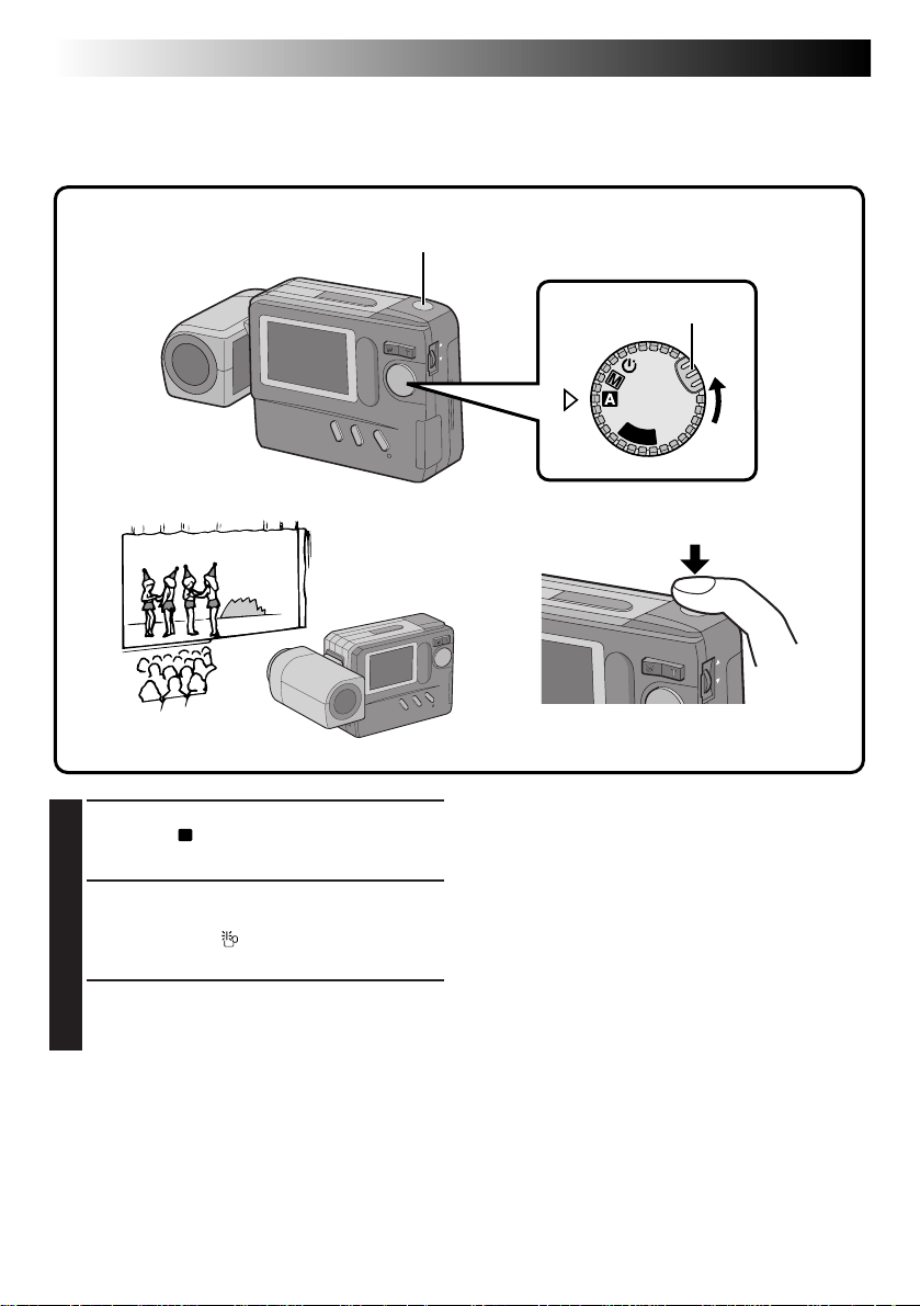
Simple Shooting (Full Auto Shooting)
In the Full Auto mode, the camera controls focusing, shutter speed, exposure and white balance automatically to make your shooting simple and easy.
Shutter Release Button
Turn the Power Dial, while pressing its Lock
1
Button, to “A”.
•The camera turns on in the Full Auto mode.
Train the lens on the subject to be photo-
2
graphed.
•If the low light “ ” icon appears on the LCD
monitor, use the flash (Z pg. 22).
Press the Shutter Release Button.
3
•The image will be stored in the built-in
memory or Compact Flash card.
Power Dial
Lock Button
OFF
Y
A
P
L
NOTES:
●
When the Shutter Release Button is half-pressed,
auto focusing is performed.
●
After storing images in the built-in memory, it is
recommended that you transfer them to a
Compact Flash card or PC.
Page 19
EN 19
Camera Setup Check
Camera setup items that can be checked include the image storage location (only when stored in a Compact
Flash card), Picture Quality mode, number of shots taken, remaining battery power, date and time. For
details, see “On-Screen Display During Shooting” (Z pg. 59, 60).
LCD monitor
CF
FINE
+2
DISPLAY Button
Standard View mode
(color display)
● Each press of the DISPLAY Button switches the View mode. The camera setup can be
checked in the Information Display Screen.
Standard View with Information Display mode
Standard View with
Information Display
mode (color display)
021/030
0001/1
JAN
1:0.0:090
PM
1198
Page 20
20 EN
BASIC OPERATION
(cont.)
Zoom Shooting
The camera incorporates a 10X zooming function that corresponds to a 43 mm to 430 mm lens of a 35 mm
camera. Zooming allows you to shoot wide areas, as well as close-ups of subjects located far away, without
changing the shooting position.
W T
W (Wide-angle) zooming
A relatively wide area can be
photographed.
T (Telescopic) zooming
A faraway subject can be
magnified and photographed.
Page 21
EN 21
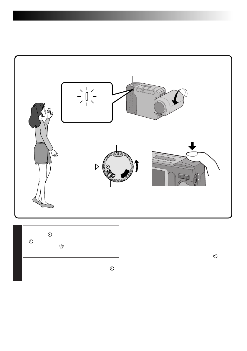
Self-Timer Shooting
When the Self-Timer is activated, the camera shutter is automatically released 15 seconds later. Once the
camera is set, the camera operator can become part of the scene. This function can also be used to prevent
blurring caused by subtle hand movements when the Shutter Release Button is pressed.
Self-Timer Lamp
Blinks.
Turn the Power Dial, while pressing its Lock
1
Button, to “ ”.
•“
” appears.
•If the low light “ ” icon appears on the LCD
monitor, use the flash (Z pg. 22).
Press the Shutter Release Button.
2
•The Self-Timer Lamp and the on-screen “ ”
icon start blinking, then the shutter is
released 15 seconds later.
Lock Button
A
Y
OFF
Power Dial
Shutter Release Button
P
L
NOTES:
●
The Self-Timer Lamp starts blinking faster when
there are 5 seconds or less remaining before the
shutter is released.
●
If you wish to cancel the Self-Timer half-way, turn
the Power Dial to any position except “ ”.
●
Focusing is performed when the Shutter Release
Button is pressed.
Page 22
22 EN
BASIC OPERATION
(cont.)
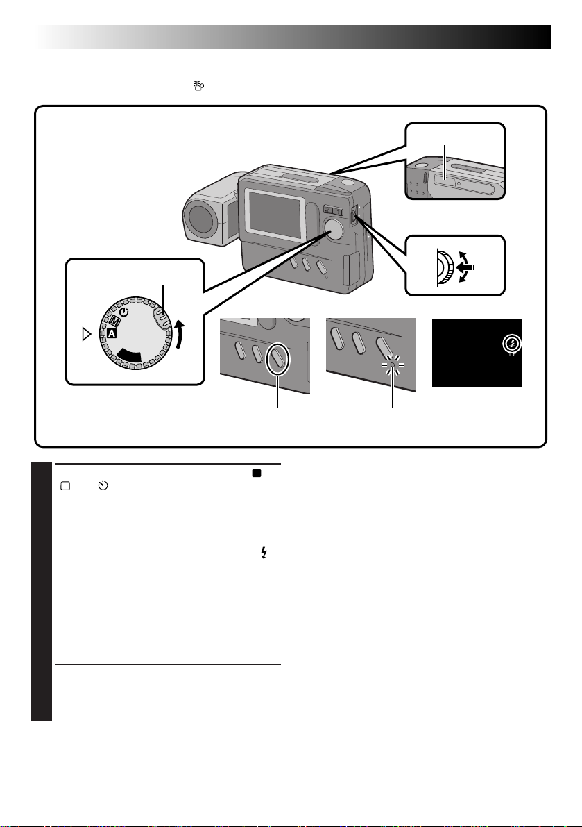
Flash Shooting
Use the flash when the low light “ ” icon appears on-screen during indoor shooting or under low light.
Flash
MENU Jog Dial
Power Dial
Lock Button
OFF
Y
A
P
L
FLASH/TRANSFER Button Flash Lamp
Make sure that the Power Dial is set to “A”,
1
“M” or “ ”, then press the FLASH/TRANSFER
Button.
•The Flash Lamp starts blinking and the flash
begins charging.
When charging is complete, the Flash Lamp
stops blinking but stays lit, and the flash “
icon appears on the LCD monitor.
•If no operation is performed while the flash
icon is displayed, the flash icon disappears.
When this occurs, press the FLASH/
TRANSFER Button again.
•To abort flash shooting before taking a
picture, press the FLASH/TRANSFER Button
again.
Aim the flash at the subject and press the
2
Shutter Release Button.
•The flash emits light and the Flash Lamp
turns off.
To take another shot with a flash . . .
.... repeat the above steps.
Flash Adjustment
The flash intensity can be increased or decreased by
2 steps. For details, see “Flash Adjustment”
(Z pg. 31).
”
NOTES:
●
While the flash is charging, the LCD monitor turns
off to save power. This is not a malfunction. Once
the flash is charged after a few seconds, the LCD
monitor turns on again.
●
When the batteries are nearly exhausted during
flash shooting, the power may turn off.
●
During Self-Recording, the flash is not charged
and does not emit light.
●
Since flash shooting consumes a large amount of
battery power, it is recommended to keep a spare
set of batteries nearby when you are planning to
take many photographs with the flash.
●
When battery power weakens, the time it takes for
the Flash Lamp to light steadily increases, and
flash charging may be aborted. Before pressing
the Shutter Release Button, make sure the Flash
Lamp stays lit.
Page 23

EN 23
Exposure Control
When the subject appears too dark or too bright on the LCD monitor, it may be necessary to compensate for
the ambient brightness. This will make it possible to capture the contours of the dark and bright regions of
the image more clearly.
NOTE:
Use the flash when the low light “ ” icon appears.
MENU Jog DialPower Dial
Lock button
P
L
A
Y
OFF
To darken the image
LCD monitor
To brighten the image
CAMERA MENU
CAMERA
P I CTURE MODE
SYSTEM
EX I T
CAMERA MENU Screen
Turn the Power Dial, while pressing its Lock
1
Button, to “M” or “ ” and push the MENU
Jog Dial.
•The CAMERA MENU Screen appears.
Rotate the MENU Jog Dial to select
2
“CAMERA” and push it.
•The CAMERA Setup Screen appears.
Rotate the MENU Jog Dial to select
3
“EXPOSURE” and push it.
•The EXPOSURE Setup Screen appears.
Rotate the MENU Jog Dial to select the
4
current value and push it.
•The item color changes to indicate that
setting is possible.
CAMERA
EXPOSURE 0
M.W. B . AUTO
SHUTTER
SPEED UTOA
EX I T
CAMERA Setup Screen
Rotate the MENU Jog Dial to adjust the
5
exposure.
•The exposure value can be selected from –6
and +6.
To brighten the image:
Increase the exposure value. (maximum +6)
To darken the image:
Decrease the exposure value. (maximum –6)
Push the MENU Jog Dial twice.
6
•The EXPOSURE Setup Screen disappears.
•The exposure value is set and the shooting
screen reappears.
To adjust a previously set exposure value . . .
.... repeat the above procedure from step 1.
NOTE:
To set the exposure value to the standard level, set
the exposure value to “0” or turn the Power Dial to
“ A”.
EXPOSURE
+6
EX I T
EXPOSURE Setup Screen
Page 24

24 EN
MANUAL SHOOTING
White Balance Control
Adjusting the White Balance
If the image appears greenish, reddish or bluish, it may be necessary to adjust the white balance of the
camera. From the list of presets (“ ”, “ ” or “ ”), select the one that makes the colors in the image look
the most natural. If the colors appear only slightly unnatural, select “AUTO”.
MENU Jog DialPower Dial
Lock Button
P
L
A
Y
OFF
LCD monitor
CAMERA MENU
CAMERA
P I CTURE MODE
SYSTEM
EX I T
CAMERA MENU Screen
CAMERA
EXPOSURE 0
M.W. B . AUTO
SHUTTER
SPEED UTOA
EX I T
CAMERA Setup Screen
M.W. B .
AUTO
MW
B
EX I T
M.W.B. Setup Screen
Turn the Power Dial, while pressing its Lock
1
Button, to “M” or “ ” and push the MENU
Jog Dial.
•The CAMERA MENU Screen appears.
Rotate the MENU Jog Dial to select
2
“CAMERA” and push it.
•The CAMERA Setup Screen appears.
Rotate the MENU Jog Dial to select “M.W.B.”
3
(Manual White Balance) and push it.
•The M.W.B. Setup Screen appears.
NOTE:
If a satisfactory white balance cannot be obtained
with any of the “ ”, “ ”, “ ” or “AUTO”
positions, adjust the white balance manually as
indicated in “Adjusting the White Balance Manually” (Z pg. 25).
Rotate the MENU Jog Dial to select “ ”,
4
“ ”, “ ” or “AUTO” and push it.
•Select the preset that can provide the subject
with the most desirable white balance.
The following 5 options can be selected.
AUTO ...... Select this position to adjust the
MWB .......Select to photograph the subject
Push the MENU Jog Dial twice.
5
•The M.W.B. Setup Screen disappears and the
shooting screen reappears.
color balance automatically. When
the Full Auto mode is selected with
the Power Dial, this position is
selected automatically.
............ Select for shooting outdoors on a
fine day.
...........Select for shooting on a cloudy day
or in the shade.
.............Select for shooting with in-
candescent lamps or video lighting,
etc.
with a previously adjusted color
balance (Z pg. 25).
Page 25

EN 25
Adjusting the White Balance Manually (M.W.B.)
If none of the preset “ ”, “ ”, “ ” or “AUTO” positions can make the colors in the image look natural,
adjust the white balance manually to obtain the most suitable color tones possible.
In step 4 on the previous page (Z pg. 24),
1
select “MWB”.
Place a sheet of white paper about 1 ft.
2
(30 cm) in front of the lens.
•Place it so that the white paper fills the
screen.
Push the MENU Jog Dial.
3
•The setting is completed after about 1
second.
•The setting can be redone by pushing the
MENU Jog Dial again.
Rotate the MENU Jog Dial to select “EXIT”
4
During indoor shooting . . .
.... the subject is exposed to a variety of light
sources, including outdoor light, fluorescent
light, candle light and so on. As the color
temperatures of these light sources vary widely,
manual white balance adjustment is recommended if you want to shoot images with the
most natural color tones possible.
When the white balance is adjusted using colored
paper . . .
.... in step 2, you can shoot images with a different
color tone than when white paper is used.
Example:
When red paper is used:
The colors will be blue-greenish.
When blue paper is used:
The colors will be amberish.
When yellow paper is used:
The colors will be purplish.
and push it 3 times.
•The M.W.B. Setup Screen disappears and the
shooting screen reappears.
To return a manually-set white balance to an
automatically-set white balance . . .
.... select “AUTO” in step 4 in the procedure on
page 24 or turn the Power Dial to “A”.
NOTE:
The manually-set white balance is held in memory
until another balance value is set by selecting
“M.W.B.”.
Page 26

26 EN
MANUAL SHOOTING
(cont.)
Shutter Speeds Selection
Selecting the Shutter Speed
The shutter speed of the camera can be selected manually, allowing a variety of expression in your pictures.
MENU Jog Dial
Power Dial
Look Button
P
L
A
Y
OFF
LCD monitor
CAMERA MENU
CAMERA
P I CTURE MODE
SYSTEM
EX I T
CAMERA MENU Screen
Turn the Power Dial, while pressing its Lock
1
Button, to “M” or “ ” and push the MENU
Jog Dial.
•The CAMERA MENU Screen appears.
Rotate the MENU Jog Dial to select
2
“CAMERA” and push it.
•The CAMERA Setup Screen appears.
Rotate the MENU Jog Dial to select
3
“SHUTTER SPEED” and push it.
•The SHUTTER SPEED Setup Screen appears.
Rotate the MENU Jog Dial to select the
4
desired shutter speed and push it twice.
•The shutter speed is selected and the
shooting screen reappears.
CAMERA
EXPOSURE 0
M.W. B . AUTO
SHUTTER
SPEED AUTO
EX I T
NOTE:
When you select a shutter speed of 1/15 sec. or less
(or 1/30 sec. or less when performing zoom or
close-up shooting), it is recommended that you use
a tripod to prevent blurring.
SHUTTER SPEED Setup ScreenCAMERA Setup Screen
UTTERHS SPEED
AUTO 1 / 10 0
1 / 8
1 /
250
1 / 1 5 1 / 5 0 0
1 / 3 0 1 / 1 0 00
EX I T
Page 27

Shutter Speeds and Effects
EN 27
Shutter Speed
AUTO
1/8 (sec.)
1/15 (sec.)
1/30 (sec.)
1/100 (sec.)
1/250 (sec.)
1/500 (sec.)
1/1000 (sec.)
Automatically selects a shutter speed according to the subject lighting.
Suitable for shooting night views. Lights from moving cars, etc. are photographed with
motion streaks. Use a tripod to avoid blurring caused by subtle hand movements.
Suitable for shooting in darkly lit environments. A slow shutter speed can collect more
light in the camera than usual, and shoot bright, clear images of hard-to-shoot subjects
in low light. Use a tripod to avoid blurring caused by subtle hand movements.
Suitable for shooting in dimly lit environments (eg. rainy day). A slow shutter speed
can collect more light in the camera than usual, and shoot bright, clear images of
hard-to-shoot subjects in low light.
Suitable for shooting under outdoor lighting conditions such as a cloudy day.
Suitable for shooting under outdoor lighting conditions such as a sunny day. This
shutter speed is not affected by subtle hand movements.
Suitable for shooting under outdoor lighting conditions such as by the seashore on a
sunny day. This shutter speed is not affected by subtle hand movements.
Allows fast-moving images to be captured one frame at a time. Use this shutter speed
under good lighting conditions.
Effect
NOTE:
If a high shutter speed is used under fluorescent lighting, hunting may occur in the image or the image color
may be changed. This is not a malfunction.
Page 28

28 EN
MANUAL SHOOTING
(cont.)
Manual Focusing
In contrast to auto focusing, where the camera automatically focuses on the subject, manual focusing can be
used when you want to intentionally change the point of focus in an image.
Power Dial
Lock Button
P
L
A
Y
OFF
Turn the Power Dial, while pressing its Lock
1
Button, to “M” or “ ”.
Press and hold the DISPLAY/M.FOCUS Button
2
for about 2 seconds.
•“ ” and “ ” appear, and the focus can be
adjusted manually.
Rotate the M.FOCUS Dial (MENU Jog Dial) to
3
focus the subject.
To focus on a farther subject . . .
Rotate the M.FOCUS Dial (MENU Jog Dial)
upward. When the focus level cannot be
adjusted any further, “ ” starts to blink.
To focus on a nearer subject . . .
Rotate the M.FOCUS Dial (MENU Jog Dial)
downward. When the focus level cannot be
adjusted any closer, “ ” starts to blink.
•2 focusing speeds are available. They can be
selected depending on how fast the
M.FOCUS Dial (MENU Jog Dial) is rotated. If
the M.FOCUS Dial (MENU Jog Dial) is
rotated quickly, the focus changes drastically.
If the M.FOCUS Dial (MENU Jog Dial) is
rotated slowly, the focus changes gradually.
Shutter Release Button
DISPLAY/M.FOCUS Button
Press the Shutter Release Button to shoot the
4
image.
NOTE:
Manual focusing is recommended in the following
cases:
●
When shooting a subject with low contrast
(variation in brightness/darkness), for example a
flat wall or blue sky.
●
When there is an obstacle such as a mesh
between the camera and the subject.
●
When the subject consists of a regular arrangement of fine patterns or similar patterns.
●
When shooting under a flickering light source
such as a fluorescent lamp.
To use auto focusing in the Manual mode (“M”) . . .
.... press and hold the DISPLAY/M.FOCUS Button
for about 2 seconds so that “ ” and “ ”
disappear.
Minimum subject distance:
The closest that this camera can focus on a subject,
with the zoom set all the way to “W”, is 3 inches
(7 cm).
M.FOCUS Dial
(MENU Jog dial)
LCD monitor
Page 29

EN 29
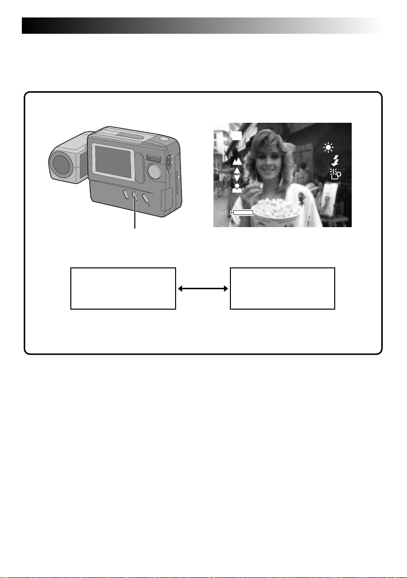
View Mode Selection
The Standard View mode displays a color image on the LCD monitor, while the Speed mode displays a
black-and-white image, but updates it more quickly to show the actual motion of the subject more faithfully.
Power Dial
Lock Button
OFF
Y
A
P
L
SPEED MODE Button
Make sure that the Power Dial is set to “M”, “A” or “ ”, then press the SPEED MODE Button.
1
•Each press of the SPEED MODE Button switches the screen as shown below.
Standard View mode
(color display)
Standard View mode
A color image is displayed on the LCD monitor and
is updated about 4 times a second. This mode is
suitable for shooting stationary subjects.
Speed mode
(monochrome display)
Speed mode
A black-and-white image is displayed on the LCD
monitor and is updated about 15 times a second.
This mode is suitable for shooting moving subjects.
• The image is stored in color.
• The on-screen display is not available.
• When the shutter speed is set to 1/8 sec. or 1/15
sec., the Quick View mode is not available.
Page 30

30 EN
MANUAL SHOOTING
(cont.)
Power Save Mode
The Power Save mode switches the camera automatically off when no operation has been performed for
more than 2 minutes.
MENU Jog Dial
Power Dial
Lock Button
P
L
A
Y
OFF
LCD monitor
CAMERA MENU
CAMERA
P I CTURE MODE
SYSTEM
EX I T
CAMERA MENU Screen SYSTEM Setup Screen POWER SAVE Screen
Turn the Power Dial, while pressing its Lock
1
Button, to “M” or “ ” and push the MENU
Jog Dial.
•The CAMERA MENU Screen appears.
Rotate the MENU Jog Dial to select “SYSTEM”
2
and push it.
•The SYSTEM Setup Screen appears.
Rotate the MENU Jog Dial to select “POWER
3
SAVE” and push it.
•The POWER SAVE Screen appears.
Rotate the MENU Jog Dial to select “ON” and
4
push it twice.
•The shooting screen reappears and the Power
Save mode is activated.
SYSTEM
POWER SAVE
FLASH ADJ .
DATE / T IME
EX I T
To deactivate the Power Save mode . . .
.... select “OFF” in step 4. When the Power Dial is
set to “A”, “M”, “ ” or “
power will stay on, even when no operations
are performed.
NOTES:
●
To switch the camera on again after it has been
switched off by the Power Save mode, turn the
Power Dial to “OFF”, wait for more than 1 second,
then turn it to “ A”, “ M”, “ ” or “
●
Do not forget to switch the camera off when not
in use, so that the batteries do not become
prematurely exhausted.
●
The Power Save mode is factory-preset to “ON”.
POWER SAVE
ON
OFF
EX I T
”, the camera
PLAY
PLAY
”.
Page 31

EN 31
Flash Adjustment
If an image shot with the flash is too dark or too bright, adjust the flash intensity as described below.
MENU Jog Dial
Power Dial
Lock Button
P
L
A
Y
OFF
LCD monitor
CAMERA MENU
CAMERA
P I CTURE MODE
SYSTEM
EX I T
Turn the Power Dial, while pressing its Lock
1
Button, to “M” or “ ” and push the MENU
Jog Dial.
•The CAMERA MENU Screen appears.
Rotate the MENU Jog Dial to select “SYSTEM”
2
and push it.
•The SYSTEM Setup Screen appears.
Rotate the MENU Jog Dial to select “FLASH
3
ADJ.” and push it.
•The FLASH ADJ. (Adjustment) Screen
appears.
SYSTEM
POWER SAVE
FLASH ADJ .
DATE / T IME
EX I T
SYSTEM Setup Screen FLASH ADJ. (Adjustment) ScreenCAMERA MENU Screen
FLASH ADJ .
+2
EX I T
Rotate the MENU Jog Dial to select the flash
4
intensity and push it.
•Select from “0”, “–1”, “–2”, “+1” and “+2”.
To brighten the flash (+1, +2) . . .
Rotate the MENU Jog Dial downward.
To darken the flash (–1, –2) . . .
Rotate the MENU Jog Dial upward.
Push the MENU Jog Dial twice.
5
•The flash adjustment value is entered and the
shooting screen reappears.
NOTES:
●
Aim the flash at the subject.
●
Even when the flash intensity is increased, the
subject may not be properly lit, depending on the
shooting conditions.
Page 32

32 EN
PLAYBACK
Playback Through a TV Monitor or VCR
By connecting the digital still camera to a TV monitor or VCR and starting playback, images can be
monitored on the TV screen or recorded onto a videotape.
TV
VCR
To VIDEO IN To VIDEO IN
Video cable
(provided)
Digital Still Camera
Core filter
To VIDEO OUT
VIDEO OUT
DC-IN
NOTES:
●
For connections to a TV monitor or VCR, refer to their instruction manuals.
●
The playback image can also be viewed on the LCD monitor of the camera without connecting it to a TV
monitor or VCR.
●
During playback on a TV monitor, indications displayed in any of the shooting modes do not appear.
Page 33

Normal Playback
Images shot with the camera are automatically
numbered, then stored in numerical order. You can
view the stored images, one at a time, much like
flipping through a photo album.
EN 33
Auto Playback
You can run through all the images stored in
memory automatically. This is like a regular slideshow.
Zoom Button
W T
Power Dial
OFF
Y
A
L
P
Lock Button
Turn the Power Dial, while pressing its Lock
1
Button, to “
•The most recently photographed image is
displayed.
•If there are no images in memory, a blue
background is displayed on the screen.
When there is more than one image in
2
memory:
Press the Zoom Button to view other images.
“T” : Displays the next image.
“W” : Displays the previous image.
PLAY
”.
NOTE:
Even if you shoot a new image after playing back a
low-numbered one, this will not overwrite an
existing image, because new images are automatically stored after the last-recorded one.
Turn the Power Dial, while pressing its Lock
1
Button, to “
•The most recently photographed image is
displayed.
Press and hold the Zoom Button for more than
2
3 seconds.
“T” : Displays images in ascending order.
“W” : Displays images in descending order.
Press the Zoom Button to stop Auto Playback.
3
•Auto Playback can be stopped by pressing
either “T” or “W”.
PLAY
”.
Page 34

34 EN
PLAYBACK
INDEX Screen
The images you shot can be displayed together with their index information. Convenient for checking
images shot beforehand, the INDEX Screen also shows the Picture Quality mode as well as which images
are protected against accidental erasure.
Selected image
INDEX
Index number
001 F 002 S 003 E
Picture Quality mode
(cont.)
004 F
001 to 999: Index number
Since this camera can store up to 999 images using
a Compact Flash card, the index numbers range
from 001 to 999. For example, when 10 images are
stored (index number: 001 to 010), if three images
with index numbers 002, 004 and 006 are deleted
from memory, the remaining images are automatically moved up to fill any gaps in the numerical
sequence. Therefore, the number of remaining
images is 7, and the new index numbers range from
001 to 007.
When images are stored in both the built-in
memory and a Compact Flash card installed in the
camera, their index images and numbers are
different from those stored using only the built-in
memory.
005 F
006 F
F/S/E: Picture Quality mode
Displays the Picture Quality mode of the stored
image. There are 3 modes available: Fine (“F”),
Standard (“S”) and Economy (“E”) (in order of
quality).
: Protect icon
When an image is protected against its accidental
erasure, a padlock mark appears next to it, and that
image cannot be deleted.
Selected Image
An image is framed like this when it is selected.
Rotate the MENU Jog Dial to move the green frame
to the desired image.
Protect icon
Page 35

EN 35
Index Playback
You can view all images stored in memory six at a time. Use this mode when looking for a image you wish
to view.
Power Dial
OFF
Y
A
L
P
Lock Button
LCD monitor
PLAY MENU
PLAY MODE
FILE
CO
MM
. MODE
EX I T
PLAY MENU Screen
PLAY MODE
I NDEX
EFFECT
FRAME
MULT I
EX I T
PLAY MODE Screen
MENU Jog Dial
INDEX
00 1 F 0 02 S 00 3 E
00 4 F
00 5 F
INDEX Screen
006 F
Turn the Power Dial, while pressing its Lock
1
Button, to “
Dial.
•The PLAY MENU Screen appears.
Rotate the MENU Jog Dial to select “PLAY
2
MODE” and push it.
•The PLAY MODE Screen appears.
Rotate the MENU Jog Dial to select “INDEX”
3
and push it.
•The INDEX Screen appears.
Rotate the MENU Jog Dial to select the image
4
to be displayed and push it.
•The image selected in the INDEX Screen is
displayed.
PLAY
” and push the MENU Jog
NOTE:
If no images are stored in memory, “PLAY MODE”
cannot be selected.
Page 36

36 EN
PLAYBACK
Protecting Images
The Protect mode helps prevent the accidental erasure of images. Put a padlock mark next to the desired
image, and that image cannot be deleted.
MENU Jog Dial
Power Dial
OFF
Y
A
L
P
Lock Button
LCD monitor
PLAY MENU
PLAY MODE
F I LE
CO
MM
. MODE
EX I T
PLAY MENU Screen
F I LE
PROTECT
DELETE
COPY
FOR MAT
EX I T
FILE Setup Screen
(cont.)
Turn the Power Dial, while pressing its Lock
1
Button, to “
Dial.
•The PLAY MENU Screen appears.
Rotate the MENU Jog Dial to select “FILE”
2
and push it.
•The FILE Setup Screen appears.
Rotate the MENU Jog Dial to select
3
“PROTECT” and push it.
•The PROTECT Screen appears.
PLAY
” and push the MENU Jog
NOTE:
When the camera’s memory is initialized, even
protected images are deleted. If you do not want to
lose important images, transfer them to a PC and
save them.
Page 37

INDEX
00 1 F 002 S 003 E
PRESS SHUTTER
AFTER SELECT
PROTECT Screen
EN 37
Rotate the MENU Jog Dial to select the image
4
to be protected (against accidental erasure)
and push it
•A padlock mark appears on the selected
image to indicate that it is protected.
•Protect each image that you do not want to
delete by accident.
Press the Shutter Release Button.
5
Push the MENU Jog Dial twice.
6
•The screen returns to the normal playback
screen.
To remove protection . . .
Perform steps 1 through 3, then rotate the MENU
Jog Dial to select the desired padlocked image and
push it. The padlock mark located above the image
disappears and the image is no longer protected.
When finished unprotecting images, perform steps 5
and 6.
Page 38

38 EN
Deleting Images
Previously shot images can be deleted either one at a time or all at once.
Power Dial
OFF
Y
A
L
P
Lock Button
LCD monitor
PLAY MENU
PLAY MODE
F I LE
CO
MM
. MODE
EX I T
PLAY MENU Screen
PLAYBACK
MENU Jog Dial
F I LE
PROTECT
DELETE
COPY
FOR MAT
EX I T
FILE Screen
(cont.)
Turn the Power Dial, while pressing its Lock
1
Button, to “
Dial.
•The PLAY MENU Screen appears.
Rotate the MENU Jog Dial to select “FILE”
2
and push it.
•The FILE Screen appears.
PLAY
” and push the MENU Jog
Rotate the MENU Jog Dial to select “DELETE”
3
and push it.
•The DELETE Screen appears.
Page 39

EN 39
LCD monitor
DELETE
DELETE Screen
ALL
SELECTED
EXI T
DELETE
001 F 002 S 003 E
Delete Select
Screen
PRESS SHUTT ER
AFT ER SEL ECT
DELETE
EXECUTE
EXI T
Deletion Confirmation Screen
To select an image by browsing images
stored in memory . . .
Before doing the following, perform steps 1 through
3 (Z pg. 38).
Rotate the MENU Jog Dial to select
4
“SELECTED” and push it.
•The Delete Select Screen appears.
Rotate the MENU Jog Dial to select an image
5
to be deleted, and push it.
•“x” appears above the selected image.
•To abort deletion of a selected image, push the
MENU Jog Dial again. The “x” mark indicating
that the image is to be deleted disappears.
Press the Shutter Release Button.
6
•The Deletion Confirmation Screen appears.
• If you want to abort deletion now, rotate the MENU
Jog Dial to select “EXIT” and push it 4 times.
Rotate the MENU Jog Dial to select
7
“EXECUTE” and push it.
•The selected images are deleted and the normal
playback screen reappears.
LCD monitor
DELETE
DELETE Screen
ALL
SELECTED
EXI T
DELETE
EXECUTE
EXI T
To delete all images . . .
Before doing the following, perform steps 1 through
3 (
Z pg. 38).
Rotate the MENU Jog Dial to select “ALL” and
4
push it.
•The Deletion Confirmation Screen appears.
Rotate the MENU Jog Dial to select “EX-
5
ECUTE” and push it.
•“DELETING IN PROGRESS” is displayed until
all images have been deleted, which can take
from a few seconds to several minutes,
depending on the number of images stored.
•If “CONTAINS PROTECTED IMAGES” is
displayed, only the unprotected images will be
deleted.
•When you also want to delete protected images,
unprotect them by referring to “To remove
protection” (Z pg. 37) before deleting all the
images.
•If you do not want to delete the images, rotate
the MENU Jog Dial to “EXIT” and push it 4
times to return to the normal playback screen.
Deletion
Confirmation
Screen
CAUTION
While protecting/unprotecting images, never remove
the Compact Flash card or disconnect power, as this
may cause the camera's built-in memory to be
corrupted. Also, be sure to use the optional AC power
adapter, as a malfunction may occur if the batteries
become exhausted halfway through the operation.
NOTES:
●
A deleted image is lost forever. To prevent accidental
deletion of important images, it is recommended that
you protect them or copy them to your PC.
●
If no images are stored in memory, “DELETE” cannot
be selected.
Page 40

40 EN
Applying Sepia/Black-and-White Effects
A sepia or black-and-white effect can be applied to a previously shot image.
Power Dial
OFF
Y
A
L
P
Lock Button
LCD monitor
PLAY MENU
PLAY MODE
F I LE
CO
MM
. MODE
EX I T
PLAY MENU Screen
PLAY MODE
I NDEX
EFFECT
FRAME
M ULT I
EX I T
PLAY MODE Screen
PLAYBACK
MENU Jog Dial
EFFECT
BLACK /WH ITE
SEP I A
ZOOM
EX I T
EFFECT Setup Screen
(cont.)
Turn the Power Dial, while pressing its Lock
1
Button, to “
Dial.
•The PLAY MENU Screen appears.
Rotate the MENU Jog Dial to select “PLAY
2
MODE” and push it.
•The PLAY MODE Screen appears.
Rotate the MENU Jog Dial to select “EFFECT”
3
and push it.
•The EFFECT Setup Screen appears.
” and push the MENU Jog
PLAY
Rotate the MENU Jog Dial to select “BLACK/
4
WHITE” or “SEPIA” and push it.
•The image is displayed with the black-andwhite or sepia effect applied to it.
•The effect is applied to other displayed
images until it is canceled.
To cancel the effect . . .
.... press the CLEAR Button.
Page 41

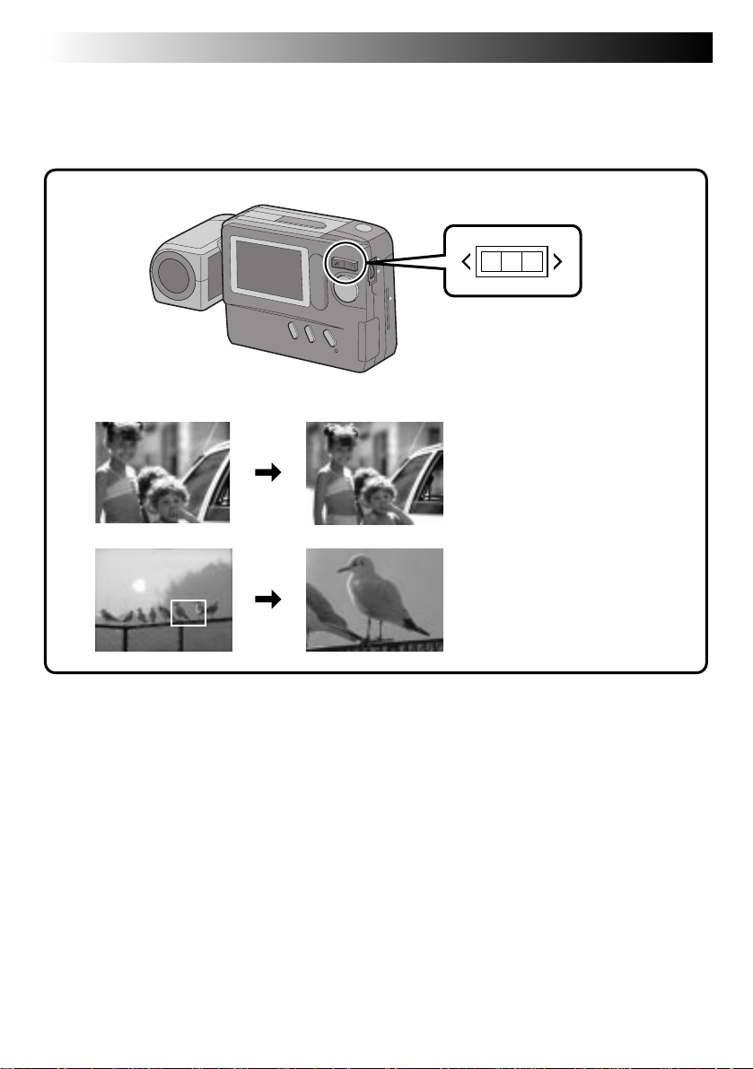
Magnifying the Playback Image (Zoom)
The zoom-in effect magnifies a selected area of image.
EN 41
Power Dial
OFF
Y
A
L
P
Lock Button
LCD monitor
PLAY MENU
PLAY MODE
F I LE
CO
MM
. MODE
EX I T
PLAY MENU Screen
Turn the Power Dial, while pressing its Lock
1
Button, to “
Dial.
•The PLAY MENU Screen appears.
Rotate the MENU Jog Dial to select “PLAY
2
MODE” and push it.
•The PLAY MODE Screen appears.
Rotate the MENU Jog Dial to select “EFFECT”
3
and push it.
•The EFFECT Setup Screen appears.
Rotate the MENU Jog Dial to select “ZOOM”
4
and push it.
PLAY
” and push the MENU Jog
PLAY MODE
I NDEX
EFFECT
FRAME
MULT I
EX I T
PLAY MODE Screen
Rotate the MENU Jog Dial to select the area
5
to be magnified, and push it.
•The selected image is split into 9 areas, from
•The effect is applied to other displayed
To cancel the effect . . .
.... press the CLEAR Button.
MENU Jog Dial
EFFECT
BLACK /WH ITE
SEP I A
ZOOM
EX I T
EFFECT Setup Screen
which you can select the area to be magnified. By rotating the MENU Jog Dial, you can
reach the desired area as indicated above.
images until it is canceled.
Page 42

42 EN
Types of Frames
An image can be displayed in 9 types of frames. The framed image can be printed out by transmitting the
image data with the frame data to a printer. Frames can also be used in 4-split or 16-split screens.
Preset frames (9 types)
PLAYBACK
(cont.)
Page 43

Framing an Image
Power Dial
OFF
Y
A
L
P
Lock Button
LCD monitor
PLAY MENU
PLAY MODE
F I LE
CO
MM
. MODE
EX I T
PLAY MENU Screen
EN 43
MENU Jog Dial
PLAY MODE
I NDEX
EFFECT
FRAME
MULT I
EX I T
FRAME Setup Screen
Turn the Power Dial, while pressing its Lock
1
Button, to “
Dial.
•The PLAY MENU Screen appears.
Rotate the MENU Jog Dial to select “PLAY
2
MODE” and push it.
•The PLAY MODE Screen appears.
Rotate the MENU Jog Dial to select “FRAME”
3
and push it.
•The FRAME Setup Screen appears.
Rotate the MENU Jog Dial to select a frame
4
and push it.
•The selected image is displayed inside the
frame.
PLAY
” and push the MENU Jog
NOTE:
Frames can also be used in 4-split or 16-split
screens (Z pg. 44).
To remove a frame . . .
.... press the CLEAR Button.
Page 44

44 EN
PLAYBACK
Multi-Image Screen
Multi-image screens that can be created are 4-split screens composed of the same image, 16-split screens
composed of the same image and 4-split screens composed of different, user-selected images.
MENU Jog Dial
Power Dial
OFF
Y
A
L
P
LCD monitor
(cont.)
Lock Button
Turn the Power Dial, while pressing its Lock
1
Button, to select “
Jog Dial.
•The PLAY MENU Screen appears.
Rotate the MENU Jog Dial to select “PLAY
2
MODE” and push it.
•The PLAY MODE Screen appears.
PLAY
” and push the MENU
PLAY MENU
PLAY MODE
F I LE
CO
MM
. MODE
EX I T
PLAY MENU Screen
Rotate the MENU Jog Dial to select “MULTI”
3
and push it.
•The MULTI Setup Screen appears.
•While a multi-image screen is being
PLAY MODE
I NDEX
EFFECT
FRAME
MULT I
EX I T
PLAY MODE Screen
displayed, it is impossible to select the
MULTI Setup Screen from the PLAY MODE
Screen. If you wish to select the MULTI Setup
Screen, first press the CLEAR Button to return
to the normal playback screen, then perform
steps 1 through 3.
Page 45

EN 45
MULT I
SAME 4
SELECTED 4
SAME 16
EXI T
MULTI Setup Screen
Multi-image screen
To Create a Multi-Image Screen Using
the Same Image
Before doing the following, perform steps 1 through
3 (Z pg. 44).
Rotate the MENU Jog Dial to select “SAME 4”
4
or “SAME 16” and push it.
•A multi-image screen displaying 4 or 16 of
the same image appears.
NOTES:
●
By printing a multi-image screen to a printer that
supports sticker sheets, you can create stickers of
any image you like. For details, read the instruction manual of your printer.
●
To create a multi-image screen with frames, first
select a frame, referring to “Framing an image”
(Z pg. 43), then make a multi-image screen.
MULT I
SAME 4
SELECTED 4
SAME 16
EXI T
MULTI Setup Screen
Multi-image screen
To Create a Multi-Image Screen Using
Selected Images
Before doing the following, perform steps 1 through
3 (Z pg. 44).
Rotate the MENU Jog Dial to select
4
“SELECTED 4” and push it.
•The MULTI Index Screen appears.
Rotate the MENU Jog Dial to select an image
5
and push it.
•“u” appears on the selected image.
To cancel the selection of an image . . .
... rotate the MENU Jog Dial to select the
image and push it. “u” disappears.
Repeat step 5 for all 4 images to be selected.
6
•The selected images are displayed in the
order they were selected in steps 5 and 6.
•A multi-image screen of the selected images
appears.
Page 46

46 EN
Compact Flash Card Operation
Installing a Compact Flash Card
A Compact Flash card increases the number images
that can be stored.
ADVANCED OPERATION
Removing a Compact Flash Card
As a Compact Flash card retains images in its
memory even after it has been removed from the
camera, it can also be used as a medium for storing
images.
NOTES:
●
Switch the camera off with the Power Dial before
installing a Compact Flash card.
●
Point the marking on the bottom of the camera
and the one on the Compact Flash card upward,
then point the marking on the Compact Flash
card at the camera and install straight in.
Align both markings.
of the camera
OFF
Y
A
P
L
DISPLAY Button
Lock Button
Power Dial
Compact Flash cardBottom panel
L
A
Y
OFF
NOTES:
●
Switch the camera off with the Power Dial.
●
Do not remove the Compact Flash card while the
camera is turned on, as this may cause the
Compact Flash card or the camera's built-in
memory to be corrupted.
Press EJECT
Jack cover
P
Install the Compact Flash card in the slot.
1
•Insert the Compact Flash card so that it fits
securely in position.
The following steps 2 and 3 are intended to
check that the Compact Flash card is
installed securely.
Turn the Power Dial, while pressing its Lock
2
Button, to “A” or “M”.
Press the DISPLAY Button.
3
•The Information Display Screen appears.
• If the CF (Compact Flash card) icon appears on
the top left of the screen, images shot hereafter
will be stored in the Compact Flash card.
NOTE:
If the CF icon does not appear on the top left of the
screen after the Compact Flash card has been installed,
switch the camera power off, remove the card and
install it again.
Open the jack cover and press the EJECT
1
Button on the bottom of the camera.
•The Compact Flash card is disengaged from
the camera.
Pull out the Compact Flash card.
2
NOTES:
●
Be sure to use only compact Flah cards bearing
the CF Trademark ( ).
●
Some brands of Compact Flash cards are not
compatible with this camera. Before purchasing a
Compact Flash card, consult its manufacturer or
dealer.
Page 47

EN 47
Initializing the Storage Media
Since the camera is a microcomputer-controlled device, external noise and interference (from a TV, a radio,
etc.) might prevent it from functioning properly. For example, when a still image you shot is stored in
memory, the above may cause the following: Although the remaining number of shots indicator shows that
shooting is possible, a still image cannot be stored in memory after shooting.
In such a case, initialize the memory by following steps 1 through 4 below. Please note that initialization
deletes all the still images (including ones for which you performed the “Protect” function) stored in
memory. If you wish to keep any of the still images that are stored in memory, before initialization first
transfer them to a PC and save them. If image data is corrupt, transfer is impossible. Normally, it is not
necessary to initialize a Compact Flash card. However, if a malfunction occurs (for example, if the image
you shot cannot be played back), then initialize the Compact Flash card.
NOTE:
Switch the camera off with the Power Dial before installing a Compact Flash card.
Preparation
Insert the Compact Flash card to be initialized.
PLAY MENU Screen
PLAY MENU
PLAY MODE
Power Dial
OFF
Y
A
L
P
FILE
CO
MM
.MODE
Lock Button
EXI T
FILE
PROT EC T
DELETE
MENU Jog Dial
FILE Screen
Turn the Power Dial, while pressing its Lock
1
Button, to “
Dial.
•The PLAY MENU Screen appears.
Rotate the MENU Jog Dial to select “FILE”
2
and push it.
•The FILE Screen appears.
Rotate the MENU Jog Dial to select
3
“FORMAT” and push it.
Rotate the MENU Jog Dial to select
4
“EXECUTE” and push it.
•The message “FORMATTING IN PROGRESS”
is displayed and formatting starts.
•When “NO IMAGES STORED” is displayed,
formatting is complete.
PLAY
” and push the MENU Jog
COPY
FORMAT
EXI T
FORMAT
EXECUT E
EXI T
FORMAT Screen
CAUTION
● Do not perform any other operation (such as
turning off the camera) during initialization,
as this may cause the camera's built-in
memory to be corrupted. Also, be sure to use
the optional AC power adapter, as the
camera’s built-in memory or the Compact
Flash card may be corrupted if the batteries
become exhausted during initialization.
● If the built-in memory is initialized, the preset
frames (
Z pg. 42) will be lost. If this occurs,
consult your nearest JVC dealer. It is still
possible to shoot and play back images
without the preset frames.
NOTES:
●
After initializing, all images stored in the compact flash card, including those which have been protected,
are cleared. Be sure to transfer important images to a PC before proceeding with initialization. However, if
image data is corrupt, it cannot be transferred to a PC.
●
Initializing a Compact Flash card does not clear images stored in the camera’s built-in memory.
●
If the message “PLEASE INITIALIZE” appears, the built-in memory needs to be initialized. Without
inserting a Compact Flash card, perform steps 1 through 4.
●
When a Compact Flash card is not installed, “FORMAT” normally cannot be selected. If it can be selected,
then the built-in memory is malfunctioning. When this occurs, make a back-up of the stored image data
before initializing.
Page 48

48 EN
Storing Images in a Compact Flash
Card
The number of images that can be shot can be
greatly increased when a Compact Flash card is
used in addition to the built-in memory. By
preparing several cards, a single camera can be
shared by several people, or they can be used to
make a library of images sorted by category.
NOTE:
Switch the camera off with the Power Dial before
installing or removing a Compact Flash card.
ADVANCED OPERATION
Playing Back Images Stored in a
Compact Flash Card
NOTE:
Switch the camera off with the Power Dial before
installing or remoing a Compact Flash card.
(cont.)
CF
FINE 001
Install the Compact Flash card in the camera.
1
Turn the Power Dial, while pressing its Lock
2
Button, to select “A”, “M” or “ ”.
•Press the DISPLAY Button to make sure the
(Compact Flash card) icon appears in the
Information Display Screen.
Shoot images.
3
•The images are automatically stored in the
Compact Flash card.
NOTES:
●
To store images in the camera’s built-in memory,
switch off the camera and remove the Compact
Flash card from the camera. See “Removing a
Compact Flash Card” (Z pg. 46).
●
To prevent the accidental erasure of images stored
in a Compact Flash card, transfer them to a
Windows® PC or Macintosh® and save them. We
also recommend that you regularly copy images
stored in a Compact Flash card to the camera's
built-in memory during shooting.
CF
Install the Compact Flash card in the camera.
1
Turn the Power Dial, while pressing its Lock
2
CF
Button, to select “
•Press the DISPLAY Button to make sure the
(Compact Flash card) icon appears in the
Information Display Screen.
Play back images.
3
•The images stored in the Compact Flash card
can be played back.
NOTE:
To play back images stored in the camera’s built-in
memory, switch off the camera and remove the
Compact Flash card from the camera. See “Removing a Compact Flash Card” (Z pg. 46).
PLAY
”.
001
CF
Page 49

PLAYBACK
(Cont.)
EN 49
Copying Images Between the Built-in Memory and a Compact Flash Card
Images can be copied from the built-in memory to a compact flash card or vice versa. This function can be
used to store especially important images separately or to exchange images.
NOTE:
Switch the camera off with the Power Dial before installing or removing a Compact Flash card.
MENU Jog Dial
Power Dial
OFF
Y
A
L
P
Lock Button
PLAY MENU
PLAY MODE
F I LE
CO
MM
. MODE
EX I T
PLAY MENU Screen
Install the Compact Flash card in the camera.
1
Turn the Power Dial, while pressing its Lock
2
Button, to “
Dial.
•The PLAY MENU screen appears.
Rotate the MENU Jog Dial to select “FILE”
3
and push it.
•The FILE Screen appears.
PLAY
” and push the MENU Jog
F I LE
PROTECT
DELETE
COPY
FORMAT
EX I T
FILE Screen
4
5
COPY
CAMERA CARD
CARD CAMERA
EX I T
COPY Screen
Rotate the MENU Jog Dial to select “COPY”
and push it.
•The COPY Screen appears.
Rotate the MENU Jog Dial to select
“CAMERA ¥ CARD” or “CARD ¥ CAMERA”
and push the MENU Jog Dial.
•The COPY Setup Screen appears.
To copy selected images only . . .
Go to step 6 on page 50.
To copy all images . . .
Go to step 6 on page 51.
Page 50

50 EN
To Copy Selected Images Only
Before doing the following, perform steps 1 through 5 on page 49.
ADVANCED OPERATION
(cont.)
COPY
ALL
SELECTED
EX I T
COPY Screen
Rotate the MENU Jog Dial to select
6
“SELECTED” and push it.
•The INDEX Screen appears.
Rotate the MENU Jog Dial to select an image
7
to be copied and push it.
•“u” appears on the selected image.
•Repeat this procedure until every image you
wish to copy is selected.
Shutter Release Button
After selecting all the images to be copied,
8
press the Shutter Release Button.
•The Copy Confirmation Screen appears.
Rotate the MENU Jog Dial to select
9
“EXECUTE” and push it.
•The message “IMAGE COPYING IN
COPY
EXECUTE
EX I T
Copy Confirmation Screen
PROGRESS” is displayed, and copying starts.
When the message disappears, copying is
complete.
Page 51

To Copy All Images
Before doing the following, perform steps 1 through 5 on page 49.
Rotate the MENU Jog Dial to select “ALL” and
6
COPY
ALL
SELECTED
EXI T
COPY Screen
push it.
•The Copy Confirmation Screen appears.
Rotate the MENU Jog Dial to select
7
“EXECUTE” and push it.
•The message “IMAGE COPYING IN
PROGRESS” is displayed, and copying starts.
When the message disappears, copying is
complete.
EN 51
COPY
EXECUTE
EXI T
Copy Confirmation Screen
NOTES:
●
While copying, never disconnect the power
supply or remove the Compact Flash card, as this
may cause the stored images to be erased or the
camera's built-in memory to be corrupted. Also,
be sure to use the optional AC power adapter, as
the camera’s built-in memory or the Compact
Flash card may be corrupted if the batteries
become exhausted during the copy operation.
●
If 5 images stored in a Compact Flash card are
copied to the built-in memory, which contains 10
stored images, the index numbers of the copied
images will be from 11 to 15.
Page 52

52 EN
ADVANCED OPERATION
(cont.)
Image Copy Using Infrared Communication [IrTran-P]
Image data can be copied between this camera and another piece of IrDA (IrTran-P) infrared communication
compatible equipment, regardless of its manufacturer.
MENU Jog Dial
Power Dial
OFF
Y
A
L
P
FLASH/TRANSFER Button
Lock Button
Turn the Power Dial, while pressing its Lock
1
Button, to “
Dial.
•The PLAY MENU Screen appears.
Rotate the MENU Jog Dial to select “COMM.
2
MODE” and push it.
•The COMM. MODE Setup Screen appears.
” and push the MENU Jog
PLAY
PLAY MENU
PLAY MODE
F I LE
CO
MM
. MODE
COMM. MODE
PC MODE
I R MODE
EX I T
EX I T
PLAY MENU Screen COMM. MODE Setup Screen
Rotate the MENU Jog Dial to select “IR
3
MODE” and push it twice.
•The normal playback screen reappears.
Page 53
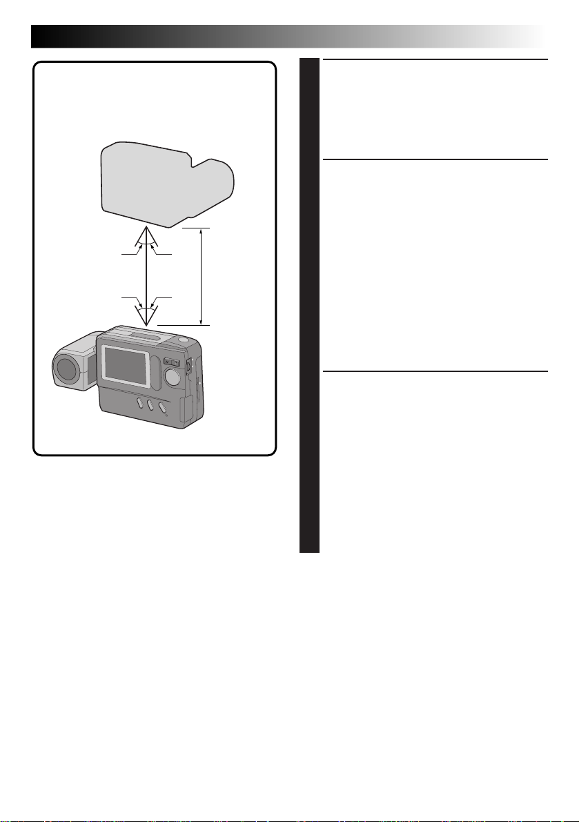
IrTran-P infrared
communication
compatible equipment
15° 15°
15° 15°
< 50 cm
Position the transmitting and receiving
4
equipment so that their infrared transmitter
and receiver face opposite each other.
•The distance between them should be less
than 1.6 ft. (50 cm), and the transmitter and
receiver should be angled no more than 15°
to each other.
If the camera is the transmitting equipment,
5
press the FLASH/TRANSFER Button.
•The message “TRANSMISSION IN
PROGRESS” is displayed, and image transfer
starts.
•During image transfer, only one image should
be displayed. If a menu screen or index
screen is displayed, transfer is impossible.
•If the message “TRANSMISSION FAILED” is
displayed 30 seconds after the FLASH/
TRANSFER Button is pressed, check the
equipment orientation, power supplies, etc.
and retry the transfer.
•To abort transfer in the middle, press the
CLEAR Button. The message “TRANSMISSION TO BE STOPPED” is displayed.
If the camera is the receiving equipment, the
6
message “RECEPTION IN PROGRESS” is
displayed.
•Reception is complete when this message
disappears.
•If the message “RECEPTION FAILED”
appears, check the equipment orientation,
power supplies, etc. and retry the transfer.
•To abort transfer in the middle, press the
CLEAR Button.
•Image data is received in the “FINE” Picture
Quality mode.
•It is recommended that you use the optional
AC power adapter during data transfer.
EN 53
Page 54

54 EN
ADVANCED OPERATION
PC Connection Operation
Picture Navigator Software (Provided)
Image data in the camera can be sent to the RS-232C port of a Windows® PC or to the modem port of a
Macintosh® or Mac OS-compatible computer.
(cont.)
Connect the PC jack of the camera to the
1
computer’s RS-232C port (Windows®), or to
its modem or printer port (Macintosh®).
Install the Picture Navigator software on your
2
computer.
Turn the Power Dial, while pressing its Lock
3
Button, to “
Dial.
•The PLAY MENU Screen appears.
Rotate the MENU Jog Dial to select “COMM.
4
MODE” and push the MENU Jog Dial.
•The COMM. MODE Setup Screen appears.
PLAY
” and push the MENU Jog
PLAY MENU
PLAY MODE
F I LE
CO
MM
. MODE
COMM. MODE
PC MODE
I R MODE
EX I T
EX I T
PLAY MENU Screen COMM. MODE Setup Screen
Rotate the MENU Jog Dial to select “PC
5
MODE” and push it twice.
•The normal playback screen reappears.
On the computer, capture the desired images
6
and process them.
•The message “PC MODE” appears during
image transfer.
•We recommend turning the camera off after
transferring images.
NOTES:
●
During image transfer to the computer, only one
image should be displayed. If a menu screen or
index screen is displayed, transfer is impossible.
●
Before transferring image data from the computer
to this camera, be sure to select the “FINE”
Picture Quality mode, referring to “Picture Mode
Selection” (Z pg. 17).
Page 55

Connection with PC
EN 55
PC connection cable for
Windows
®
(provided)
To COM
(RS-232C)
port
Windows
®
PC
PC
PC jack
PC connection cable for
Macintosh® (provided)
Core filterCore filter
To modem port
U
P
or printer port
Macintosh
®
NOTES:
●
Use the AC power adapter when connecting to the computer.
●
Be sure to read the instruction manuals of the provided “Picture Navigator” software and your computer.
Page 56

56 EN
CONTROLS, CONNECTORS AND INDICATORS
4
2
8
Lock button
OFF
Y
A
P
L
6
1
3
7
9
0
5
PC
^
@
#
!
VIDEO OUT
&
DC-IN
%
$
Page 57

Front View
1 Shutter Release Button .............. Z pg. 14
Press when you wish to shoot.
2 Flash........................................ Z pg. 22
Lights when shooting under low light or
back light conditions.
3 Flash Sensor ............................. Z pg. 22
Be careful not to cover this area when
using the flash.
4 Infrared Beam Sensor ............... Z pg. 53
Transmits/receives image data via infrared
beam.
5 Lens ........................................ Z pg. 14
Train on the subject.
6 Self-Timer Lamp ....................... Z pg. 21
Blinks when the Self-Timer is activated.
7 PC Jack .................................... Z pg. 55
Connect to the RS-232C port (Windows
or to the modem or printer port
(Macintosh
®
) of your computer.
®
)
EN 57
Rear View
8 Power Dial ............................... Z pg. 16
Turn while pressing its Lock Button to
select a shooting mode or the playback
mode.
9 Zoom Button ............................ Z pg. 20
Press to zoom during shooting or to switch
to the next/previous image during playback.
0 MENU/BRIGHT/M.FOCUS
Jog Dial ........................
Turn to adjust settings for shooting or
playback, to adjust the brightness of the
LCD monitor or to adjust the focus.
! BATTERY Cover ........................ Z pg. 10
Open to replace the batteries.
@ SPEED MODE Button ................ Z pg. 29
Press to cycle through the Standard View
mode or the Speed mode while shooting.
CLEAR Button ..........................
Press to clear an effect.
# DISPLAY/M.FOCUS
Button ...............................
Press to make the on-screen display
appear/disappear, or to focus on a subject
manually.
$ Flash Lamp ............................... Z pg. 22
Lights when the flash is ready.
% FLASH/TRANSFER Button ... Z pg. 22, 52
Press to transfer images by infrared beam
or to charge the flash.
^ VIDEO OUT Jack ..................... Z pg. 32
Connect to a VCR, TV monitor or video.
& DC-IN Jack .............................. Z pg. 11
Connect to the optional AC power adapter.
Z pg. 12, 15, 28
Z pg. 40
Z pg. 19, 28
Page 58

58 EN
CONTROLS, CONNECTORS AND INDICATORS
12
(cont.)
34
Bottom View
1 EJECT Button............................ Z pg. 46
Press to eject the optional Compact Flash
card.
2 Tripod Mounting Socket
When attaching a tripod, insert the
threaded section of the tripod in this hole
and turn to secure. Use only tripods not
equipped with a stud that prevents the
camera from rotating.
3 Hand Strap Eyelet
Thread the provided hand strap through
this eyelet.
Hand Strap Attachment
Loop
2
5
4 Compact Flash Card Slot ........... Z pg. 46
Insert an optional Compact Flash card. For
Z pg. 46.
details,
5 Reset Switch
Allows you to reset the camera to its
factory presets. First, remove the power
supply (AC power adapter, batteries, etc.),
then insert a pin or similar object into this
hole.
Open the jack cover.
1
Thread the end of the hand strap through the
2
camera's eyelet, then thread the loop of the
hand strap through the end.
1
3
Close the cover.
3
Page 59
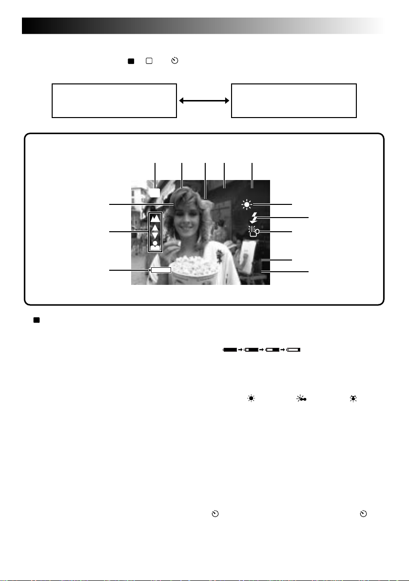
EN 59
On-Screen Display During Shooting
When the Power Dial is set to “A”, “M” or “ ”, press the DISPLAY Button to change the View mode.
Each press of the DISPLAY Button switches the screen as shown below.
Standard View mode
(color display)
12345
CF
6
+2
7
8
CF
1
Icon ..................................... Z pg. 48
Appears when images are being stored in a
Compact Flash card.
2 Picture Quality Mode ............... Z pg. 17
Displays the selected Picture Quality mode
(FINE/STD/ECONOMY).
3 Shutter Speed........................... Z pg. 26
4 Number of Shots Taken
Shows the number of images that have
already been shot.
5 Total Number of Shots
Displays the total number of shots that can
be stored, including those already taken.
6 Exposure Value ......................... Z pg. 23
7 Focus Indicator ........................ Z pg. 28
Displays manual focusing adjustments.
Standard View with Information
Display mode (color display)
021/FINE 030
0001/1
9
0
!
1198
JAN
1:0.0:090
PM
8 Battery Power Remaining
Displays the approximate battery power
remaining:
Nearly exhausted: mark turns red.
9 White Balance .......................... Z pg. 24
Displays the current setting when any
white balance except AUTO is selected
(Fine “
Manual White Balance “M.W.B.”).
0 Flash Icon ................................ Z pg. 22
Appears when the flash is charged.
! Low Light Icon ......................... Z pg. 22
Appears when the flash is required.
@ Date Display (Month/Day/Year) ... Z pg. 12
# Time Display ............................ Z pg. 12
Indication During Self-Timer
Mode ...........................................
: Appears when the Power Dial is set to “ ”.
When the Shutter Release Button is pressed, this
indicator blinks and the Self-Timer is activated.
”/Cloudy “ ”/Halogen“ ”/
@
#
Z pg. 21
Page 60

60 EN
CONTROLS, CONNECTORS AND INDICATORS
On-Screen Display During Shooting (cont.)
(Cont.)
12 3
CF
FINE 001
Information Displayed Between Shutter
Release and Storage of Image in Memory
CF
1
Icon ..................................... Z pg. 48
Appears when the image is stored in a
Compact Flash card.
2 Picture Quality Mode (FINE/STD/
ECONOMY) .............................
3 Image Number
Displays the index number given to the
image file.
Z pg. 17
4
5
Icons Displayed During Manual Focusing
These icons are displayed when manual focusing is
selected.
4Far .......................................... Z pg. 28
Rotate the M.FOCUS Dial (MENU Jog Dial)
upward to focus on a farther subject. When
rotating the M.FOCUS Dial (MENU Jog
Dial),
5 Near ........................................ Z pg. 28
Rotate the M.FOCUS Dial (MENU Jog Dial)
downward to focus on a nearer subject.
When rotating the M.FOCUS Dial (MENU
Jog Dial),
is displayed.
is displayed.
Page 61

On-Screen Display During Playback
When the Power Dial is set to “
playback screen.
Each press of the DISPLAY Button switches the screen as shown below.
”, press the DISPLAY Button to view the information display over the
PLAY
EN 61
Playback image
12 34
CF
7
CF
1
Icon ..................................... Z pg. 48
Appears when an image stored in a
Compact Flash card is played back.
2 Picture Quality Mode................ Z pg. 17
Displays the Picture Quality mode used for
the image.
3 Image Number
Displays the index number given to the
image file.
4 Total Number of Images
Displays the total number of stored images.
Playback image and
information display
021/FINE 030
1198
JAN
1:0.0:090
PM
5 Date ........................................ Z pg. 12
6 Time ........................................ Z pg. 12
7 Battery Power Remaining
Displays the approximate battery power
remaining:
Nearly exhausted: mark turns red.
5
6
Page 62

62 EN
As this digital still camera is controlled by a microcomputer, it may occasionally malfunction due to noise or
interference. In such a case, remove the power supply (batteries or AC power adapter), push the Reset
Switch (Z pg. 58) and retry using the camera. If the trouble still persists and it cannot be solved by referring
to the following table, please consult your nearest JVC dealer.
TROUBLESHOOTING
SYMPTOM CORRECTIVE ACTION PAGE
Power
No power is supplied.
● Is the battery dead?
● Are the batteries loaded in the correct direction?
● Is the power supply connected properly?
Shooting
The LCD monitor flickers in the
Standard View mode (color display).
Shooting is impossible.
Images do not appear.
The menu screens are not available.
Although the Shutter Release Button
is half-pressed, focusing is not
possible.
Images become dark when sunlight
is captured by the camera.
The LCD monitor is dark or whitish.
The message “MEMORY FULL”
appears.
Images take on a strobe-like effect.
There is color noise in the image.
During flash shooting, power turns
off.
Noise appears on the image you are
shooting or there is noise in the
taken shot.
● The battery power is low. Replace the batteries.
● Is the Power Dial set to “
● Switch off the camera, then on again.
● Is the Power Dial set to “A”?
● Is focusing set to manual adjustment?
● Are you shooting under low light or are you
shooting a subject which has no contrast?
● This is not a malfunction.
● Turn the lens to adjust the LCD monitor angle or
adjust the brightness.
● Is the image being played back in a cold place?
In cold areas, the LCD monitor appears slightly
dark. This is not a malfunction.
● The LCD monitor's lamp is reaching the end of
its service life. Consult your nearest JVC dealer.
● When the built-in memory is full and no more
shooting is possible, this message appears. Use a
blank Compact Flash card or transfer the stored
images to a Windows® PC or Macintosh® and
save them. Then, delete the images from the
camera's built-in memory to make room for new
shots.
● This is not a malfunction.
● This is not a malfunction.
● During flash shooting, if the remaining battery
power is half-full or less, the power may turn off.
● Noise may appear in strong magnetic or electric
fields (ex. near a radio tower, etc.). This is not
due to any defect of the camera.
PLAY
”?
49–54
10
11
10
16
16
16
28
—
14
38
—
—
22
—
Page 63

SYMPTOM CORRECTIVE ACTION PAGE
Others
The image on the LCD monitor
appears distorted.
The date/time is not displayed
properly.
A Compact Flash card cannot be
inserted.
None of the buttons or controls
function on the camera.
Small colored or black spots appear
on the LCD monitor.
Preset frame images do not appear.
● Is the surface or the edge of the LCD monitor
being pressed? If so, release your hand and
leave it for a while.
● The remaining power of the built-in clock
battery is close to nil. Connect the camera to the
AC power adapter and plug it in for over 24
hours.
● Is the Compact Flash card being held in the
correct direction?
● Switch the camera off, remove the power supply
(battery or AC power adapter) and press the
Reset Switch on the bottom of the camera with a
pin or similar object. All settings are returned to
their factory presets.
● The LCD monitor is manufactured using highprecision technology, however, a few pixels on
it may be always off (black) or on (lit). This is
not due to any defect of the camera. (Functioning dots: more than 99.99%)
● If the built-in memory is initialized after the
message “PLEASE INITIALIZE” appears, the
preset frames are erased. Consult your nearest
JVC dealer.
EN 63
—
11
46
11
58
—
47
Page 64

64 EN
Display Description
NO IMAGES STORED
CONTAINS PROTECTED IMAGES
TRANSMISSION IN PROGRESS
RECEPTION IN PROGRESS
TOO MANY COPIES
IMAGE COPYING IN PROGRESS
FORMATTING IN PROGRESS
TRANSMISSION TO BE STOPPED
RECEPTION TO BE STOPPED
TRANSMISSION FAILED
RECEPTION FAILED
PC MODE
DELETING IN PROGRESS
PLEASE INITIALIZE
DISPLAY AND MESSAGES
● Appears during playback when no images are stored in the
built-in memory or Compact Flash card.
● Appears when there are protected images in the camera when
all-image deletion is attempted. In this case, all images can be
deleted by unprotecting the protected images.
● Appears while the camera is transmitting image data via the IR
communication system.
● Appears while the camera is receiving image data via the IR
communication system.
● Appears when copying is impossible because there is not
enough space at the destination. Either make space at the
destination or reduce the number of images to be copied.
● Appears while image data is being copied.
● Appears while a Compact Flash card or the built-in memory is
being initialized.
● Appears when image transmission is cancelled.
● Appears when image reception is cancelled.
● Appears when data was not sent due to failure.
● Appears when data was not received due to failure.
● Appears during image transmission through a PC connection.
● Appears while the camera is deleting images.
● Appears when a malfunction occurs in the built-in memory.
When this appears, initialize the built-in memory.
Page 65
CAUTIONS
When using the AC Power Adapter in areas other
than the USA
n The provided AC Power Adapter features
automatic voltage selection in the AC range from
110 V to 240 V.
USING HOUSEHOLD AC PLUG ADAPTER
In case of connecting the unit’s power cord to an
AC wall outlet other than American National
Standard C73 series type use an AC plug adapter,
called a “Siemens Plug”, as shown.
For this AC plug adapter, consult your nearest JVC
dealer.
Plug adapter
AC Power Adapter (Optional)
1. To prevent fire, electric shock or injury . . .
.... DO NOT use the AC power adapter with any
power source or voltage not supported.
.... DO NOT modify or disassemble the AC
power adapter. Never attempt to repair or
check it yourself, as this is very dangerous.
Consult your nearest JVC dealer for maintenance on the AC power adapter.
.... DO NOT connect any power cord other than
the one provided to the AC power adapter. If
the power cord's performance or design is
different, fire or electric shock may result.
.... first connect the power cord to the AC power
adapter. If the power cord is connected first
to an AC outlet, and the AC power adapter's
connector comes in contact with a metallic
object, a short-circuit will occur which may
result in fire or injury.
2. To prevent fire, malfunction or electric
shock . . .
.... DO NOT use any AC power adapter except
the one specified with this digital still
camera. If the AC adapter's performance or
design is different than what the digital
camera is designed for, fire, malfunction or
electric shocks may result. Before using,
thoroughly read the instructions of the digital
still camera and the AC power adapter.
3. To avoid malfunction . . .
.... connect the power cord to the AC power
adapter securely. If the power cord is
disconnected during use of the camera,
shooting or playback may become impossible and the image data may become corrupt.
EN 65
Batteries
•This camera requires 4 AA (LR6)-size alkaline
batteries. AA (LR6)-size nickel-cadmium (Ni-Cd)
or nickel-metal hydrode (Ni-MH) batteries can
also be used. Note that the battery power
remaining indicated by the camera does not take
the type of batteries being used into account.
•Do not use manganese dioxide or carbon zinc
batteries as they do not have sufficient energy to
power this camera.
•Use the batteries properly. The wrong use can
cause them to leak, or become hot or damaged.
When replacing the batteries, insert them with
their (+) and (–) polarity marks properly aligned, as
indicated by the orientation marking inside the
battery cover.
•When the batteries become cold in cooler
temperatures [below 10 °C (50 °F)], such as
outdoors in winter, their lifetime shortens and they
may cease to function. If this happens, place the
batteries in your pocket or other warm, protected
place for a short time, then re-insert them in the
camera. We recommend using AA (LR6)-size
nickel-cadmium batteries as they can power the
camera even at 0°C. (32°F)
•If the (+) and (–) polarity marks are dirty with
sweat or oil, this will cause contact failure. Wipe
them off with a dry cloth, then use the batteries.
•Keep new batteries handy if you plan to use the
camera for an extended period of time (for travel,
etc.).
•Before using Ni-Cd or Ni-MH batteries, be sure to
charge them fully using their designated battery
charger.
•Since batteries become hot after they are exhausted, be careful when replacing them with
new ones.
•If the batteries are not used for an extended
period, remove them from the camera to avoid
battery leakage, which can cause malfunctions to
occur.
•Do not use different kinds of batteries or old and
new batteries together.
•Do not expose the batteries to excessive heat, as it
may cause them to leak or explode.
•Do not dispose of batteries in fire.
•Do not shortcircuit the terminals. Keep them away
from metallic objects when not in use.
Page 66

66 EN
Built-in Rechargeable Battery
To store the date/time in memory, a rechargeable
battery is integrated in the camera. As long as the
camera is connected to an AC outlet using the AC
power adapter, or the batteries installed in the
camera continue to supply power to the camera, the
built-in battery is always charged. However, if the
camera is not used for approx. 3 months, the builtin battery will become discharged and the date/time
stored in memory will be lost. When this occurs,
connect the camera to an AC outlet using the AC
power adapter for over 24 hours to charge the builtin rechargeable battery. Before using the camera
again, set the date/time.
Note that it is possible to use the camera without
setting the date/time.
Main Unit
1. For safety, DO NOT . . .
.... open the camera’s chassis.
.... disassemble or modify the unit.
.... allow inflammables, water or metallic objects
to enter the unit.
.... remove the batteries or disconnect the power
supply while the power is on.
2. Avoid using the unit . . .
.... in places subject to excessive humidity or
dust.
.... in places subject to soot or steam such as
near a cooking stove.
.... in places subject to excessive shock or
vibration.
.... near a television set.
.... near appliances generating strong magnetic
or electric fields (speakers, broadcasting
antennas, etc.).
.... in places subject to extremely high (over
40°C or 104°F) or extremely low (under 0°C
or 32°F) temperatures.
3. DO NOT leave the unit . . .
.... in places of over 50°C (122°F).
.... in places where humidity is extremely low.
(below 35%) or extremely high (above 80%).
.... in direct sunlight.
.... in a closed car in summer.
.... near a heater.
CAUTIONS
(Cont.)
4. To protect the unit, DO NOT . . .
.... allow it to become wet.
.... drop the unit or strike it against hard objects.
.... subject it to shock or excessive vibration
during transportation.
.... keep the lens directed at extremely bright
objects for long periods.
.... carry it by holding the lens. Be sure to hold
the main unit with both hands.
.... swing it excessively when using the hand
strap.
LCD Monitor
1. To prevent damage to the LCD monitor,
DO NOT . . .
.... push it strongly or apply any shocks.
.... place the camera with the LCD monitor on
the bottom.
2. To prolong service life . . .
.... avoid rubbing it with coarse cloth.
3. Be aware of the following phenomena for
LCD monitor use. These are not malfunctions . . .
•While using the camera, the surface around the
LCD monitor and/or the back of the LCD monitor
may heat up.
•If you leave power on for a long time, the surface
around the LCD monitor becomes hot.
How To Handle A CD-ROM
•Take care not to soil or scratch the mirror surface
(opposite to the printed surface). Do not write
anything or put a sticker on either the front or
back surface. If the CD-ROM gets dirty, gently
wipe it with a soft cloth outward from the center
hole using a circular motion.
•Do not use conventional disc cleaners or cleaning
spray.
•Do not bend the CD-ROM or touch its mirror
surface.
•Do not store your CD-ROM in a dusty, hot or
humid environment. Keep it away from direct
sunlight.
Page 67

EN 67
About moisture condensation . . .
● You may have observed that pouring a cold
liquid into a glass will cause drops of water to
form on the glass’ outer surface. This same
phenomenon occurs on the lens of the
camera when it is moved from a cool place to
a warm place, after heating a cold room,
under extremely humid conditions or in a
place directly subjected to the cool air from
an air conditioner.
Serious malfunctioning
If malfunctioning occurs, stop using the unit
immediately and consult your local JVC dealer.
Declaration of Conformity
Model Number : GC-S1U
Trade Name : JVC
Responsible party : US JVC CORP.
Address : 41 Slater Drive,
Elmwood Park, N. J.
07407
Telephone Number : (201) 794–3900
This device complies with Part 15 of FCC Rules.
Operation is subject to the following two
conditions:
(1) This device may not cause harmful
interference, and (2) this device must accept
any interference received, including interference that may cause undesired operation.
Change or modifications not approved by the
party responsible for compliance could void the
user’s authority to operate the equipment. This
equipment has been tested and found to
comply with the limits for a Class B digital
device, pursuant to Part 15 of the FCC Rules.
These limits are designed to provide reasonable
protection against harmful interference in a
residential installation. This equipment
generates, uses, and can radiate radio frequency
energy and, if not installed and used in
accordance with the instructions, may cause
harmful interference to radio communications.
However, there is no guarantee that interference
will not occur in a particular installation. If this
equipment does cause harmful interference to
radio or television reception, which can be
determined by turning the equipment off and
on, the user is encouraged to try to correct the
interference by one or more of the following
measures:
Reorient or relocate the receiving antenna.
Increase the separation between the equipment and receiver.
Connect the equipment into an outlet on a
circuit different from that to which the
receiver is connected.
Consult the dealer or an experienced radio/
TV technician for help.
This Class B digital apparatus complies with
Canadian ICES-003.
Cet appareil numérique de la classe B est
conforme à la norme NMB-003 du Canada.
Page 68

68 EN
Dimensions : 129 (W) x 74 (H) x 39 (D) mm (5-1/8" x 2-15/16" x 1-9/16")
Power consumption : 4.2 W
Weight : Approx. 260 g (0.58 lbs)
Power : DC 6 V
Flash : Built-in,
Effective shooting distance: 0.5 to 2 m
(with zoom set all the way to “W”)
LCD monitor : 1.8”
Tripod mounting socket : Provided on the bottom panel
Storage media : Built-in flash memory (storage capacity: approx. 3 MB),
Compact Flash card (Commercially available)
Compression system : JPEG (compatible)
CCD : 1/4”, 350,000 pixel, progressive scan, complementary color
CCD
Focal distance : 4.5 to 45 mm
(equivalent to 43 mm to 430 mm on a 35 mm camera)
Zoom : 10X optical zoom
Filter diameter : 27 mm
Aperture (F-number) : F1.6
Minimum subject distance : Approx. 7 cm
Photometry method : TTL CCD photometry
Shutter system : Electronic shutter
Shutter speeds : Auto/Manual (1/8 to 1/1000 sec.)
White balance : Auto/Manual (Fine/Cloudy/Halogen/M.W.B.)
Focusing : Auto/Manual (7 cm to
Picture quality : 3 modes (Fine/Standard/Economy)
Number of storable images : Fine : approx. 30
Standard : approx. 50
Economy : approx. 100
PC jack : 2.5 mm dia., 3-pole plug
Video output jack : 3.5 mm dia., 2-pole plug (NTSC)
DC input jack :6 V
Infrared transmitter/receiver : IrDA Ver. 1.0 (IrTran-P compatible)
MAJOR SPECIFICATIONS
)
E. & O. E. Design and specifications subject to change without notice.
Page 69

INDEX
A
AC outlet.................................. pg. 11
AC power adapter .................... pg. 11
Alkaline batteries ..................... pg. 10
Auto playback .......................... pg. 33
B
Battery power remaining .......... pg. 59, 61
Black-and-white effect ............. pg. 40
C
Camera setup check ................. pg. 19
Compact Flash card ................. pg. 46
Connection to PC ..................... pg. 55
Copy ........................................ pg. 49 – 51
D
Date/time ................................. pg. 12
Deleting images ....................... pg. 38, 39
E
Effects ...................................... pg. 40, 41
Exposure compensation ........... pg. 23
F
Flash ........................................ pg. 22, 31
Frames ..................................... pg. 42, 43
Focusing .................................. pg. 28
Formatting................................ pg. 47
Full Auto shooting .................... pg. 18
I
Index playback......................... pg. 35
INDEX screen........................... pg. 34
Infrared image
communication ...................... pg. 52, 53
Infrared transmitter/receiver ..... pg. 53
IrDA transfer ............................ pg. 52
IrTran-P .................................... pg. 52
EN 69
M
Manual focusing ...................... pg. 28
Manual white balance
(M.W.B.) ................................ pg. 24, 25
Multi-image screen .................. pg. 44, 45
N
Normal playback ..................... pg. 33
P
Picture Quality mode ............... pg. 17
Playback mode ........................ pg. 33
Power Save mode .................... pg. 30
Power supply ........................... pg. 10, 11
Protecting images ..................... pg. 36, 37
S
Self-Timer................................. pg. 21
Sepia effect .............................. pg. 40
Shooting modes ....................... pg. 16
Shutter speeds .......................... pg. 26, 27
T
TV monitor............................... pg. 32
V
View modes ............................. pg. 29
W
White balance.......................... pg. 24, 25
Z
Zoom-in effect ......................... pg. 20, 41
16-split screen.......................... pg. 44, 45
4-split screen............................ pg. 44, 45
Page 70

70 EN
FOR SERVICING (Only in U.S.A.)
HOW TO LOCATE YOUR JVC SERVICE CENTER
TOLL FREE: 1-800-252-5722
Dear customer:
In order to receive the most satisfaction from your purchase, read the instruction booklet before
operating the unit. In the event that repair is necessary, or for the address nearest your location,
please refer to the factory service center list below or within the Continental United States, call 1-800252-5722 for your authorized servicer. Remember to retain your Bill of Sale for Warranty Service.
— JVC
JVC SERVICE & ENGINEERING
COMPANY OF AMERICA
DIVISION OF US JVC CORP.
FACTORY SERVICE CENTER LOCATIONS
107 Little Falls Road 1500 Lakes Parkway 705 Enterprise Street
Fairfield, NJ 07004-2105 Lawrenceville, GA 30243-5857 Aurora, IL 60504-8135
(973) 808-9279 (770) 339-2522 (630) 851-7855
5665 Corporate Avenue 10700 Hammerly Blvd., Suite 110 2969 Mapunapuna Place, Suite 101
Cypress, CA 90630-4727 Houston, TX 77043-2310 Honolulu, HI 96819-2000
(714) 229-8011 (713) 935-9331 (808) 833-5828
230 Eliot Street 8192 West State Road 84 890 Dubuque Avenue
Ashland, MA 01721-2377 Davie, FL 33324-4611 South San Francisco, CA 94080-1804
(508) 881-5923 (954) 472-1960 (415) 871-2666
Sophisticated electronic products may require occasional service. Just as quality is a keyword in the
engineering and production of the wide array of JVC products, service is the key to maintaining the
high level performance for which JVC is world famous. The JVC service and engineering organization
stands behind our products.
NATIONAL HEADQUARTERS
JVC SERVICE & ENGINEERING COMPANY OF AMERICA
DIVISION OF US JVC CORP.
107 Little Falls Road
Fairfield, NJ 07004-2105
If you ship the product...
Pack your JVC unit in the original carton or one of equivalent size and strength. Enclose, with the unit,
a letter stating the problem or symptom that exists and also a copy of the receipt or bill of sale you
received when you purchased your JVC unit. Print your home return address on the outside and the
inside of the carton. Send to the appropriate JVC Factory Service Center as listed above.
ACCESSORIES
To purchase accessories for your JVC product, you
may contact your local JVC Dealer.
Or from the 48 Continental United States call toll free:
1-800-882-2345.
Don't service it yourself.
CAUTION
To prevent electrical shock, do not open the
cabinet. No user serviceable parts inside.
Refer servicing to qualified service personnel.
Page 71

WARRANTY (Only in U.S.A.)
EN 71
LIMITED WARRANTY
JVC COMPANY OF AMERICA warrants this product and all parts thereof, except as set forth below ONLY TO
THE ORIGINAL PURCHASER AT RETAIL to be FREE FROM DEFECTIVE MATERIALS AND WORKMANSHIP
from the date of original retail purchase for the period as shown below. ("The Warranty Period")
PARTS
THIS LIMITED WARRANTY IS VALID ONLY IN THE FIFTY (50) UNITED STATES, THE DISTRICT OF
COLUMBIA AND IN COMMONWEALTH OF PUERTO RICO.
WHAT WE WILL DO:
If this product is found to be defective, JVC will repair or replace defective parts at no charge to the original owner.
Such repair and replacement services shall be rendered by JVC during normal business hours at JVC authorized
service centers. Parts used for replacement are warranted only for the remainder of the Warranty Period. All
products and parts thereof may be brought to a JVC authorized service center on a carry-in basis except for
Television sets having a screen size 25 inches and above which are covered on an in-home basis.
WHAT YOU MUST DO FOR WARRANTY SERVICE:
Return your product to a JVC authorized service center with a copy of your bill of sale. For your nearest JVC
authorized service center, please call toll free: (800) 252-5722.
If service is not available locally, box the product carefully, preferably in the original carton, and ship, insured, with
a copy of your bill of sale plus a letter of explanation of the problem to the nearest JVC Factory Service Center,
the name and location of which will be given to you by the toll-free number.
If you have any questions concerning your JVC Product, please contact our Customer Relations Department.
WHAT IS NOT COVERED:
This limited warranty provided by JVC does not cover:
1. Products which have been subject to abuse, accident, alteration, modification, tampering, negligence, misuse,
faulty installation, lack of reasonable care, or if repaired or serviced by anyone other than a service facility
authorized by JVC to render such service, or if affixed to any attachment not provided with the products, or if
the model or serial number has been altered, tampered with, defaced or removed;
2. Initial installation and installation and removal for repair;
3. Operational adjustments covered in the Owner's Manual, normal maintenance, video and audio head cleaning;
4. Damage that occurs in shipment, due to act of God, and cosmetic damage;
5. Signal reception problems and failures due to line power surge;
6. Video Pick-up Tubes/CCD Image Sensor, Cartridge, Stylus (Needle) are covered for 90 days from the date of
purchase;
7. Accessories;
8. Batteries (except that Rechargeable Batteries are covered for 90 days from the date of purchase);from the date
of purchase);
There are no other express warranties except as listed above.
THE DURATION OF ANY IMPLIED WARRANTIES INCLUDING THE IMPLIED WARRANTY OF
MERCHANTABILITY, IS LIMITED TO THE DURATION OF THE EXPRESS WARRANTY HEREIN.
JVC SHALL NOT BE LIABLE FOR THE LOSS OF USE OF THE PRODUCT, INCONVENIENCE, LOSS OR ANY
OTHER DAMAGES, WHETHER DIRECT, INCIDENTAL OR CONSEQUENTIAL (INCLUDING, WITHOUT
LIMITATION, DAMAGE TO TAPES, RECORDS OR DISCS) RESULTING FROM THE USE OF THIS PRODUCT,
OR ARISING OUT OF ANY BREACH OF THIS WARRANTY. ALL EXPRESS AND IMPLIED WARRANTIES,
INCLUDING THE WARRANTIES OF MERCHANTABILITY AND FITNESS FOR PARTICULAR PURPOSE, ARE
LIMITED TO THE WARRANTY PERIOD SET FORTH ABOVE.
Some states do not allow the exclusion of incidental or consequential damages or limitations on how long an
implied warranty lasts, so these limitations or exclusions may not apply to you. This warranty gives you specific
legal rights and you may also have other rights which vary from state to state.
JVC COMPANY OF AMERICA 41 Slater Drive
DIVISION OF US JVC CORP. Elmwood Park, New Jersey 07407
1 YR
LABOR
90 DAYS
CONSUMER VIDEO 1-90
REFURBISHED PRODUCTS CARRY A SEPARATE WARRANTY, THIS WARRANTY DOES NOT APPLY. FOR
DETAILS OF REFURBISHED PRODUCT WARRANTY, PLEASE REFER TO THE REFURBISHED PRODUCT
WARRANTY INFORMATION PACKAGED WITH EACH REFURBISHED PRODUCT.
For customer use:
Enter below the Model No. and Serial No. which is located either on the rear, bottom or side of the cabinet. Retain
this information for future reference.
Model No.: Serial No:
Purchase date: Name of dealer:
Page 72

GC-S1
COPYRIGHT© 1998 VICTOR COMPANY OF JAPAN, LTD.
U
Printed in Japan
0398MNV*UN*VP
VICTOR COMPANY OF JAPAN, LIMITED
 Loading...