

Page 1

DIGITAL STILL CAMERA
GC-S1
Please visit our CyberCam Homepage on
the World Wide Web and answer our
Consumer Survey (in English only):
ENGLISH
http://www.jvc-victor.co.jp/index-e.html
STILL CAMERA
INSTRUCTIONS
LYT0143-001A
EN
Page 2
2 EN
Dear Customer,
Thank you for purchasing the Digital Still Camera. Before use, please read the safety information and
precautions contained in the following pages to ensure safe use of your new camcorder.
Using This Instruction Manual
•All major sections and subsections are listed in the Table Of Contents (Z pg. 6, 7).
•Notes appear after most subsections. Be sure to read these as well.
•Basic and advanced features/operation are separated for easier reference.
It is recommended that you . . .
.... refer to “CONTROLS, CONNECTORS AND INDICATORS” (
familiarize yourself with button locations, etc. before use.
.... read thoroughly the Safety Precautions and Safety Instructions that follow. They contain extremely
important information regarding the safe use of your new camcorder.
You are recommended to carefully read the cautions on pages 63 – 65 before use.
SAFETY PRECAUTIONS
Z pgs. 54 – 59) and
IMPORTANT (For Customers in U.K.)
Connection to the mains supply in the United
Kingdom.
DO NOT cut off the mains plug from this
equipment. If the plug fitted is not suitable for
the power points in your home or the cable is
too short to reach a power point, then obtain an
appropriate safety approved extension lead or
consult your dealer.
BE SURE to replace the fuse only with an
identical approved type, as originally fitted,
and to replace the fuse cover.
If nonetheless the mains plug is cut off ensure to
remove the fuse and dispose of the plug
immediately, to avoid a possible shock hazard
by inadvertent connection to the mains supply.
If this product is not supplied fitted with a mains
plug then follow the instructions given below:
DO NOT make any connection to the Larger
Terminal coded E or Green.
The wires in the mains lead are coloured in
accordance with the following code:
Blue to N (Neutral) or Black
Brown to L (Live) or Red
If these colours do not correspond with the
terminal identifications of your plug, connect as
follows:
Blue wire to terminal coded N (Neutral) or
coloured black.
Brown wire to terminal coded L (Live) or
coloured Red.
If in doubt — consult a competent electrician.
WARNING:
TO PREVENT FIRE OR SHOCK
HAZARD, DO NOT EXPOSE
THIS UNIT TO RAIN OR
MOISTURE.
CAUTIONS:
n To prevent shock, do not open the cabinet.
No user serviceable parts inside. Refer
servicing to qualified personnel.
n When you are not using the AC Power
Adapter for a long period of time, it is
recommended that you disconnect the power
cord from AC outlet.
NOTES:
●
The rating plate (serial number plate) and
safety caution are on the bottom and/or the
back of the main unit.
●
The rating plate (serial number plate) of the
AC Power Adapter is on its bottom.
This camera is designed to be used with PALtype colour television signals. It cannot be used
for playback with a television of a different
standard. However, shooting and LCD monitor
playback are possible anywhere.
Page 3
EN 3
CAUTION:
To avoid electric shock or damage to the unit,
first firmly insert the small end of the power
cord into the AC Power Adapter until it is no
longer wobbly, and then plug the larger end of
the power cord into an AC outlet.
This unit is produced to comply with Standard
IEC Publ. 65.
SOME DO’S AND DON’TS ON THE SAFE USE
OF EQUIPMENT
This equipment has been designed and manufactured to meet international safety standards
but, like any electrical equipment, care must be taken if you are to obtain the best results and
safety is to be assured.
read the operating instructions before you attempt to use the equipment.
DO
DO ensure that all electrical connections (including the mains plug, extension leads and interconnections
between pieces of equipment) are properly made and in accordance with the manufacturer’s instructions. Switch off and withdraw the mains plug when making or changing connections.
DO consult your dealer if you are ever in doubt about the installation, operation or safety of your equip-
ment.
DO be careful with glass panels or doors on equipment.
DON’T continue to operate the equipment if you are in any doubt about it working normally, or if it is
DON’T remove any fixed cover as this may expose dangerous voltages.
DON’T leave equipment switched on when it is unattended unless it is specifically stated that it is designed
DON’T use equipment such as personal stereos or radios so that you are distracted from the requirements
DON’T listen to headphones at high volume, as such use can permanently damage your hearing.
DON’T obstruct the ventilation of the equipment, for example with curtains or soft furnishings. Overheating
DON’T use makeshift stands and NEVER fix legs with wood screws — to ensure complete safety always fit
DON’T allow electrical equipment to be exposed to rain or moisture.
ABOVE ALL
— NEVER let anyone especially children push anything into holes, slots or any other opening in the case
— NEVER guess or take chances with electrical equipment of any kind — it is better to be safe than sorry!
damaged in any way — switch off, withdraw the mains plug and consult your dealer.
for unattended operation or has a standby mode. Switch off using the switch on the equipment and
make sure that your family knows how to do this. Special arrangements may need to be made for
infirm or handicapped people.
of road safety. It is illegal to watch television whilst driving.
will cause damage and shorten the life of the equipment.
the manufacturer’s approved stand or legs with the fixings provided according to the instructions.
— this could result in a fatal electrical shock;
Page 4
4 EN
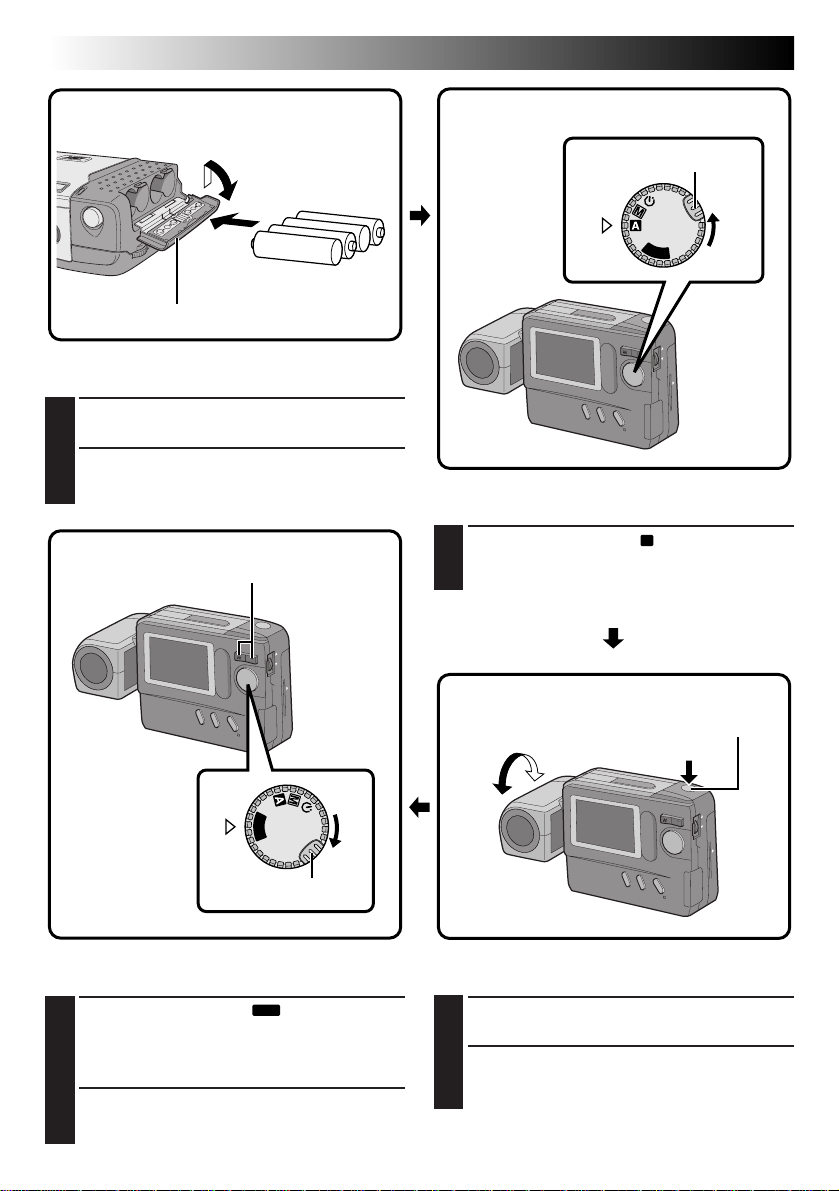
1
Four LR6 (AA)-size
alkaline batteries
2
BATTERY cover
Load batteries. (Z pg. 8)
Slide the BATTERY cover slightly to open.
1
Insert four LR6 (AA)-size batteries as indicated
2
by the orientation marking inside the cover.
Zoom Button
2
QUICK START
Power Dial
Lock button
OFF
Y
A
P
L
Turn the power on. (Z pg. 14)
Turn the Power Dial to “A”.
1
•Turn while holding the Lock Button depressed.
1
Power Dial
OFF
Y
A
L
P
Lock button
Play an image. (Z pg. 31)
Turn the Power Dial to “
1
•Turn while holding the Lock Button depressed.
•A still image stored in memory appears.
Select an image with the Zoom Button.
PLAY
”.
2
Shutter Release Button
190°
2
1
Shoot an image. (Z pg. 16)
Tilt the lens and point it at the subject.
1
Press the Shutter Release Button.
2
•A still image is stored in the camera's
memory.
Page 5
MAJOR FEATURES
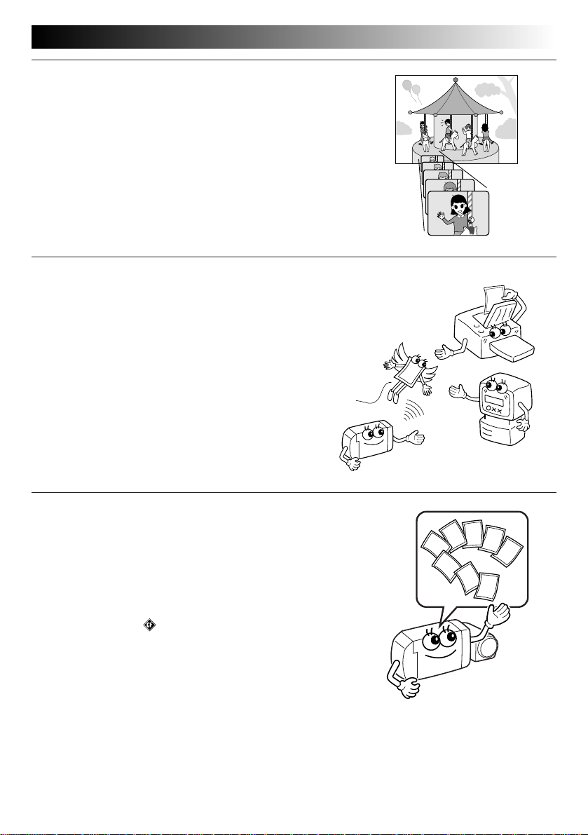
10X Zooming for Magnifying Faraway Subjects
When a subject is located too far away to be approached, its image
can be enlarged using 10X zooming.
An image shot by zooming has much higher quality than a nonzoomed image enlarged using image processing software on a PC.
Cordless Image Transfer Using Infrared Communication (IrTran-P Compatible)
IrTran-P is the most advanced infrared communication protocol
available today.
Images can be transferred to another piece of equipment without
using a cable, provided that it is compatible with the IrTran-P
standard.
EN 5
Compact Flash Card for Shooting More Images
The Compact Flash card makes it possible to shoot and store
images in addition to those that can be stored in the built-in
memory.
The extra available images mean you don’t have to worry about
missing great shots. Also, by using several Compact Flash cards,
you can make a library of images archived by category, or you can
create personal archives for each person when a single camera is
shared by several users.
COMPACTFLASH and are trademarks of SanDisk Corporation,
registered in the U.S.A. and other countries.
Page 6

6 EN
CONTENTS
SAFETY PRECAUTIONS
QUICK START
MAJOR FEATURES
CONTENTS
GETTING STARTED
Loading Batterirs ............................................................................... 8
Unloading Batteries ............................................................................ 8
Hand Strap Attachment ........................................................................ 8
Houehold Power Supply ....................................................................... 9
Date/Time Setting ........................................................................... 10
BASIC OPERATION
Lens Adjustment .............................................................................. 12
Shutter Release Button ...................................................................... 12
Brightness Control............................................................................ 13
Shooting Mode Selection .................................................................... 14
Picture Mode Selection ...................................................................... 15
Simple Shooting (Full Auto Shooting) ...................................................... 16
Camera Setup Check ......................................................................... 17
Zoom Shooting................................................................................ 18
Self-Timer Shooting .......................................................................... 19
Flash Shooting ................................................................................ 20
MANUAL SHOOTING
Exposure Control ............................................................................. 21
White Balance Control ....................................................................... 22
Adjusting the White Balance ............................................................. 22
Adjusting the White Balance Manually (M.W.B.) ..................................... 23
Shutter Speed Selection ..................................................................... 24
Selecting the Shutter Speed.............................................................. 24
Shutter Speeds and Effects .............................................................. 25
Manual Focusing .............................................................................. 26
View Mode Selection ........................................................................ 27
Power Save Mode............................................................................ 28
Flash Adjustment ............................................................................. 29
PLAYBACK
Playback Through a TV Monitor or VCR................................................... 30
Normal Playback ............................................................................. 31
Auto Playback ................................................................................ 31
INDEX Screen ................................................................................. 32
Index Playback ............................................................................... 33
Protecting Images ............................................................................ 34
Deleting Images .............................................................................. 36
2
4
5
6
8
12
21
30
Page 7
Applying Sepia/Black-and-White Effects ................................................. 38
Magnifying the Playback Image (Zoom) .................................................. 39
Types of Frames .............................................................................. 40
Framing an Image ............................................................................ 41
Multi-Image Screen .......................................................................... 42
APPLIED OPERATIONS
Compact Flash Card Operation.............................................................. 44
Installing a Compact Flash Card ......................................................... 44
Removing a Compact Flash Card ........................................................ 44
Initializing the Storage Media .............................................................. 45
Storing Images in a Compact Flash Card .................................................. 46
Playing Back Images Stored in a Compact Flash Card ................................... 46
Copying Images Between the Built-in Memory and a Compact Flash Card ........... 47
Image Copy Using Infrared Communication [IrTran-P] .................................. 50
Printing on a Digital Printer [IrDA Transfer] .............................................. 52
PC Connection Operation .................................................................... 53
CONTROLS, CONNECTORS AND INDICATORS
TROUBLESHOOTING
DISPLAY AND MESSAGES
CAUTIONS
MAJOR SPECIFICATIONS
INDEX
EN 7
44
54
60
62
63
66
67
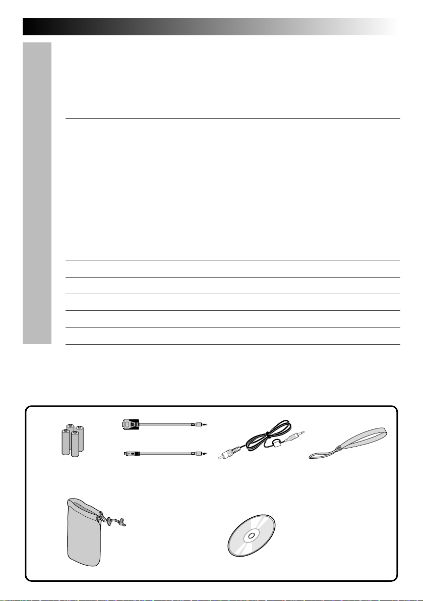
PROVIDED ACCESSORIES
x 1 for Windows
LR6 (AA)-size
alkaline battery x 4
x 1 for Macintosh
PC connection cable
Soft case
®
PC
®
Video cable Hand strap
CD-ROM
• Picture Navigator
• MGI PhotoSuite SE
Page 8
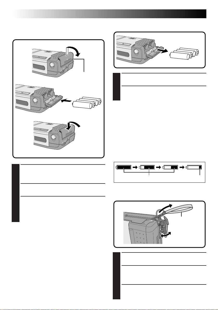
8 EN
Loading Batteries
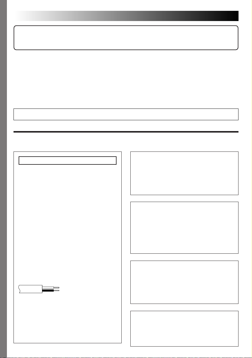
Use LR6 (AA)-size dry cell batteries.
1
GETTING STARTED
Unloading Batteries
2
BATTERY
Cover
3
Slide the battery cover (BATTERY) slightly to
1
open.
•The battery cover opens.
Insert batteries as indicated by the orientation
2
marking inside the battery cover.
Close the battery cover and slide it back.
3
•The battery cover is locked in the closed
position.
•Make sure the battery cover is closed
securely.
Open the battery cover by performing step 1
1
of “Loading Batteries” to the left.
Take out batteries by tilting the camera
2
slightly.
NOTES:
●
Do not use manganese batteries as they do not
have sufficient energy to power this camera.
●
If the batteries are not used for an extended
period, remove them from the camera to avoid
battery leakage, which can cause malfunctions to
occur.
●
Since batteries become very hot after they are
exhausted, be careful when replacing them with
new ones.
●
Replace the batteries when the battery power
remaining indicator displays the red mark.
green
red
Hand Strap Attachment
2
Loop
NOTES:
●
Commercially-available LR6 (AA)-size nickel-
cadmium (Ni-Cd) or nickel-metal hydride (NiMH) batteries can also be used. Ni-Cd or Ni-MH
batteries are more economical because they can
be recharged and used repeatedly. Be sure to read
their instructions.
●
Inserting batteries in the incorrect direction may
cause them to leak.
1
3
Open the jack cover.
1
Thread the end of the hand strap through the
2
camera's eyelet, then thread the loop of the
hand strap through the end.
Close the cover.
3
Page 9
EN 9
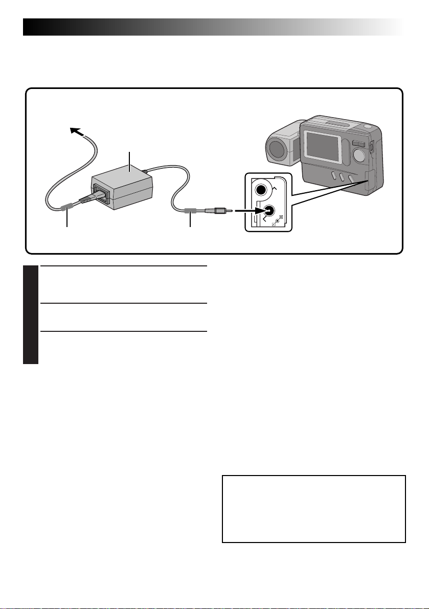
Household Power Supply
When using the camera indoors, it is more convenient and economical to power it from a household AC
power outlet using an AC power adapter (optional).
To AC outlet
3
AA-V33 AC power
adapter (optional)
1
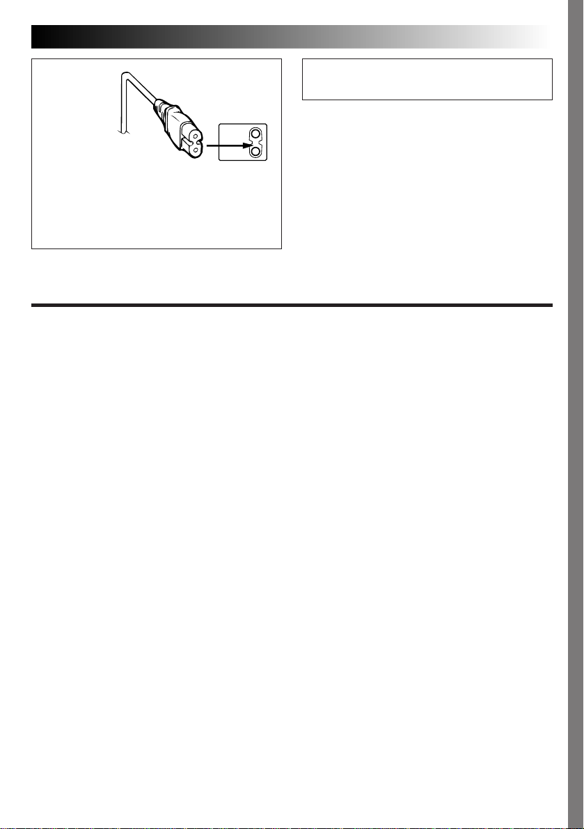
Core filter Core filter
Connect the Power Cord to the AC Power
1
Adapter.
•Make sure connections are secure.
Connect the DC Cord to the DC Input
2
Connector of the Digital Still Camera.
Connect the Power Cord to an AC outlet.
3
•After use, unplug the Power Cord from the
AC outlet.
2
VIDEO OUT
DC-IN
NOTES:
●
The optional AA-V33 AC Power Adapter features
automatic voltage selection in the AC range from
110 V to 240 V.
●
Make sure the Power Cord is securely connected
to the AC Power Adapter.
●
When using the AC Power Adapter, use only the
Power Cord provided with the AC Power Adapter.
Use of any other cord may result in shock or fire.
●
Connect the Power Cord to the AC Power Adapter
before connecting it to an AC outlet. If you plug it
into an outlet first, and the Adapter’s terminals
come in contact with a metal surface or object,
short circuit or fire may result.
●
Vibration noise can sometimes be heard coming
from the inside of the AC Power Adapter. This is
normal.
●
The AC Power Adapter processes electricity
internally, and will become warm during use. This
is normal. Make sure to use the AC Power
Adapter in well-ventilated areas only.
ATTENTION:
Before detaching the power source, make
sure that the camera’s power is turned off.
Failure to do so may cause the camera’s
built-in memory to be corrupted.
Page 10
10 EN
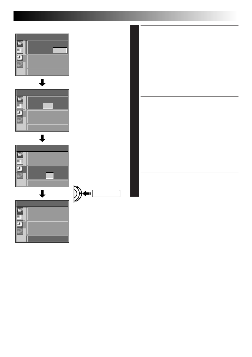
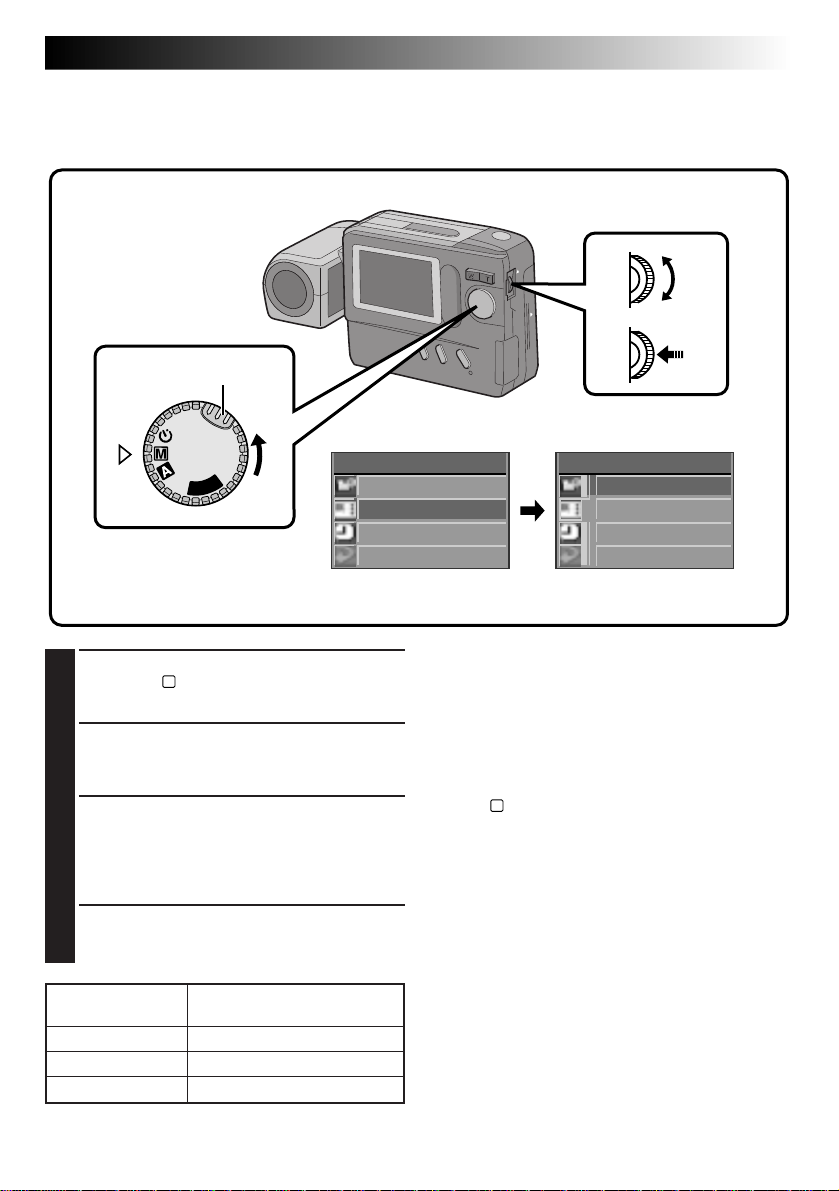
GETTING STARTED
Date/Time Setting
By setting the date and time, date/time data can be viewed along with your pictures.
Date/time data is also convenient for categorizing pictures later.
Power Dial
Lock Buton
P
L
A
Y
OFF
(cont.)
MENU Jog Dial
LCD monitor
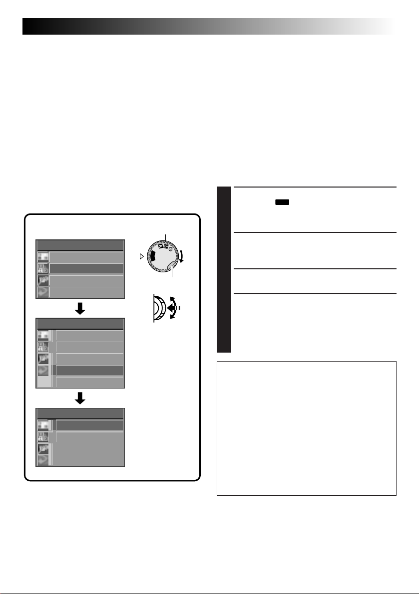
CA MERA MENU
CA MERA
PICTURE MODE
SYSTEM
EXI T
SYSTEM
POWER SAVE
FLASH ADJ .
DATE / T IME
EXI T
DATE / T IME
DATE
27 . 12 .1998
TIME
9:30
EXI T
CAMERA MENU
Screen
SYSTEM Setup Screen
DATE/TIME Setup
Screen
24-hour indication
Turn the Power Dial, while pressing its Lock
1
Button, to “M” and push the MENU Jog Dial.
•The CAMERA MENU Screen appears.
Rotate the MENU Jog Dial to select “SYSTEM”
2
and push it.
•The SYSTEM Setup Screen appears.
Rotate the MENU Jog Dial to select “DATE/
3
TIME” and push it.
•The DATE/TIME Setup Screen appears.
•If you wish to set only the time without
changing the date, go to step 5.
Page 11
LCD monitor
DATE / T IME
DATE
27 . 12 .1998
TIME
9:30
EXI T
DATE / T IME
DATE
27 . 12 . 1998
TIME
9:30
EXI T
DATE / T IME
DATE
27 . 12 .1998
TIME
14 :20
EXI T
DATE / T IME
DATE
27 . 12 .1998
TIME
14 :20
EXI T
DATE/TIME Setup
Screen
14 :20:00
EN 11
Set the values for the date.
4
1. Rotate the MENU Jog Dial to select the item
in the “DATE” section you wish to set and
push it.
•The item colour changes to indicate that
setting is possible.
2. Rotate the MENU Jog Dial until the correct
setting appears and push it.
•Repeat this procedure until you are
satisfied with the date settings.
• If you wish to set only the date without
changing the time, go to step 6.
Set the values for the time.
5
1. Rotate the MENU Jog Dial to select the item
in the “TIME” section you wish to set and
push it.
•The item colour changes to indicate that
setting is possible.
2. Rotate the MENU Jog Dial until the correct
setting appears and push it.
•When the MENU Jog Dial is pushed after
the minutes are set, “EXIT” is selected and
clock operation starts from 0 seconds.
•Repeat this procedure until you are
satisfied with the time settings.
Rotate the MENU Jog Dial to select “EXIT”
6
and push it 3 times.
•The shooting screen reappears and the clock
starts functioning.
NOTES:
●
The date/time setting is backed up by a built-in
rechargeable clock battery. Connect the camera
to an AC outlet using the AC power adapter for
over 24 hours to charge the clock battery.
●
The clock will continue to advance except while
the minutes are being set. When the minutes are
set and the MENU Jog Dial is pushed, the seconds
are reset to “0” and clock operation starts.
●
Although the date/time which you have set is
stored in the camera’s built-in memory, the date/
time display will not be combined with the
pictures you shoot.
Page 12
12 EN
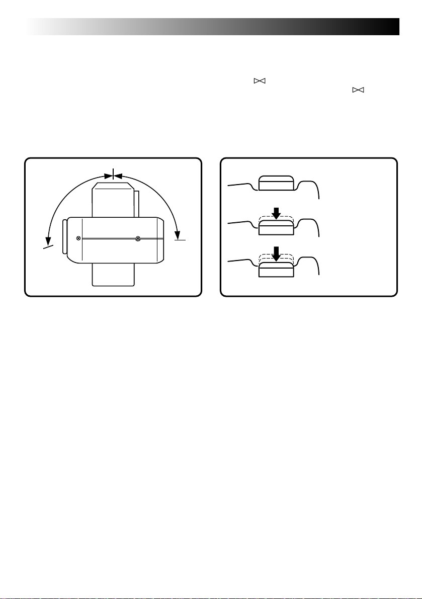
Lens Adjustment
To obtain the most stable position for shooting
while viewing the LCD monitor, hold the lens so
that it forms an angle of 45 degrees in relation to
the camera body.
The lens tilts up to 100 degrees forward and 90°
backward. You can photograph yourself, while
viewing your own image on the LCD monitor (SelfRecording), by tilting the lens 90 degrees backward
and taking your picture. This can be used for things
such as keeping a photo diary.
100° 90°
BASIC OPERATION
Shutter Release Button
The Shutter Release Button of the camera has two
steps. At the first step, when the button is pressed
halfway, “ ” is displayed and the camera
automatically focuses on the subject. “ ”
disappears once the subject has been brought into
focus.
The operation of pressing the Shutter Release Button
to the first step is called a “half-press”. From the
“half-pressed” position, press the button all the way
to the second step.
Unpressed
position
Half-pressed
position
Fully-pressed
position
NOTES:
●
Do not press the Shutter Release Button with your
finger raised over the button or do not press it
with too strong a force, as this may disrupt the
horizontal positioning of the image or cause
blurring. When shooting, always half-press the
button before pressing it fully to the second step.
●
If focusing is performed by pressing the Shutter
Release Button frequently during auto focus, the
period between when the Shutter Release Button
is pressed and when the shutter is released will be
shortened.
●
While the camera is performing auto focusing
with the button half-pressed, the displayed image
may freeze temporarily. This is not a malfunction.
●
When the Shutter Release Button is released from
the half-pressed position and half-pressed again,
the camera performs auto focusing again.
Page 13
EN 13
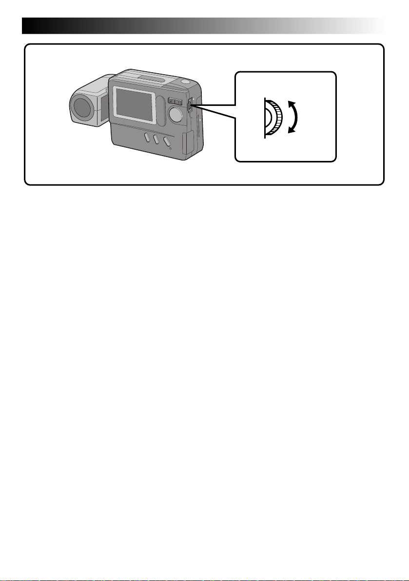
BRIGHT Dial (MENU Jog Dial)
To darken the image
To brighten the image
Brightness Control
You can adjust the brightness of the LCD monitor by rotating the BRIGHT dial, except during manual
focusing or menu adjustment.
To darken the image . . .
Rotate the BRIGHT dial upward.
To brighten the image . . .
Rotate the BRIGHT dial downward.
Page 14
14 EN
BASIC OPERATION
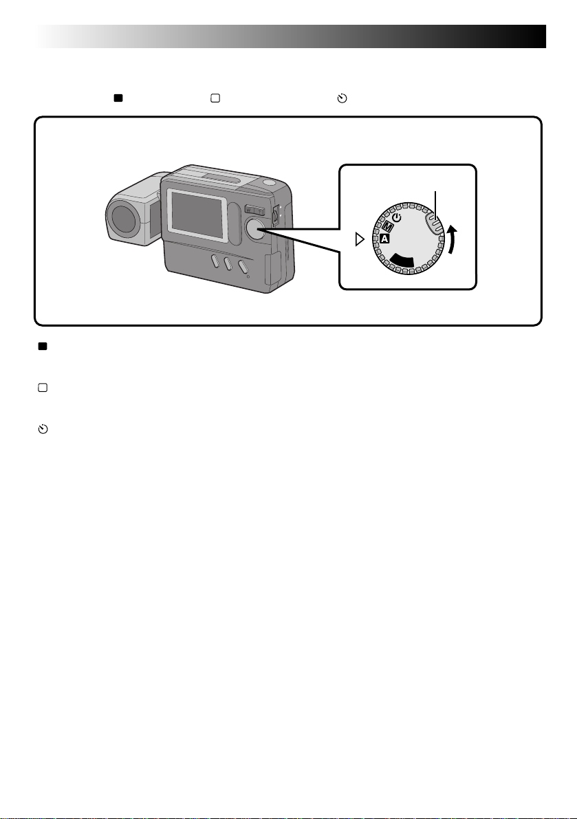
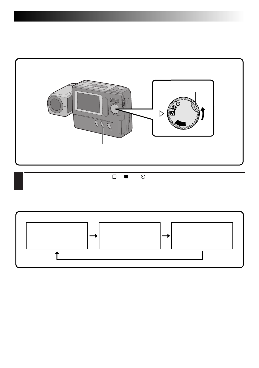
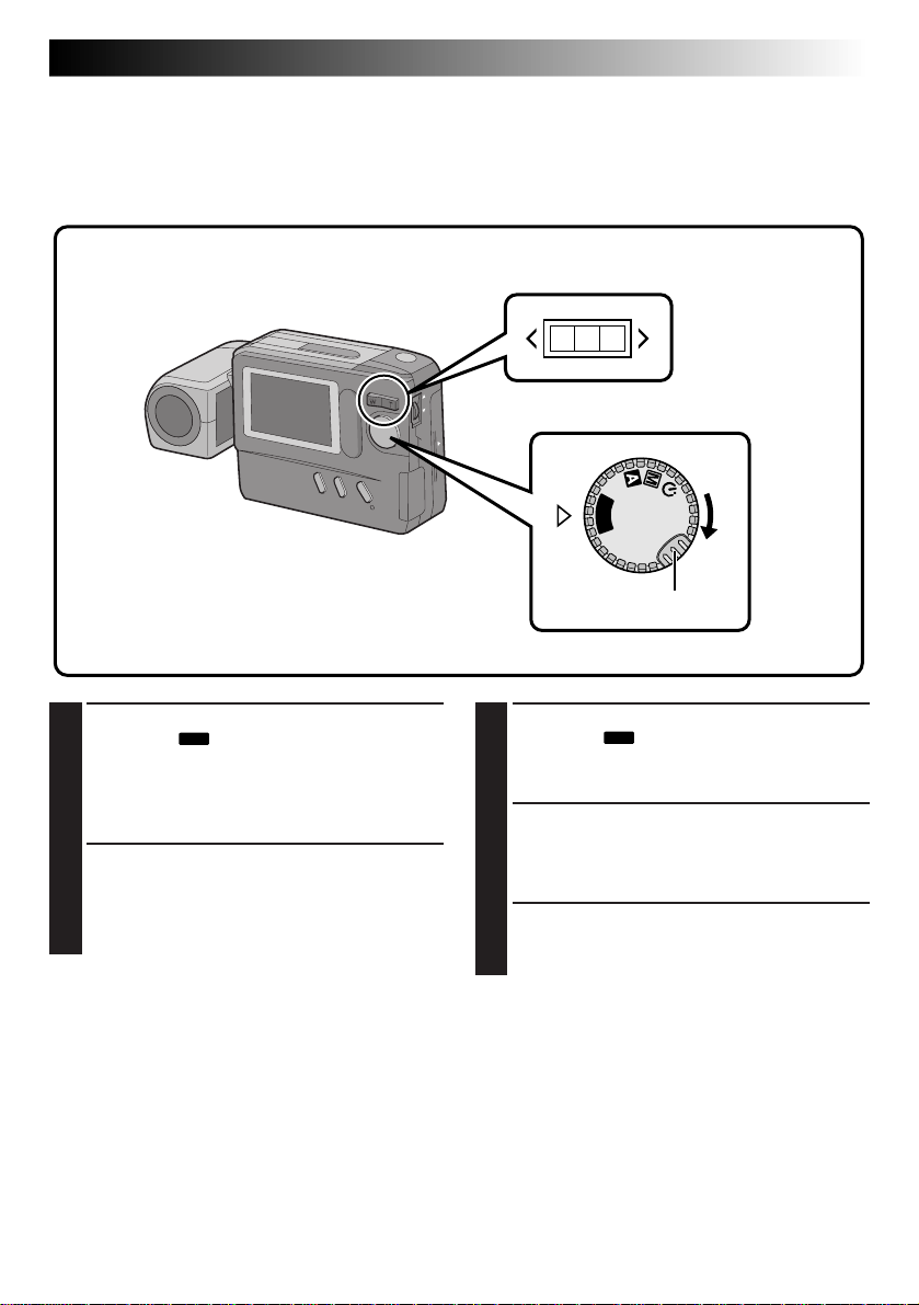
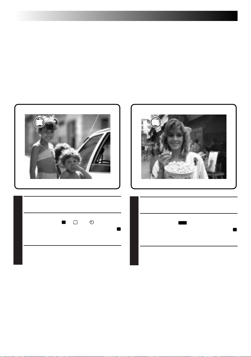
Shooting Mode Selection
Turning the Power Dial allows you to select the appropriate shooting mode from among the following:
Full Auto mode ( A ), Manual mode ( M ) and Self-Timer mode ( ).
Power Dial
Lock Button
OFF
Y
A
P
L
“
A
” : Full Auto mode
The camera will automatically control all items including exposure, shutter speed, focusing and
white balance.
“
M
” : Manual mode
Exposure, shutter speed, focusing and white balance can be controlled manually according to the
shooting conditions.
“
” : Self-Timer mode
A 15-second self-timer can be used.
(cont.)
Page 15
EN 15
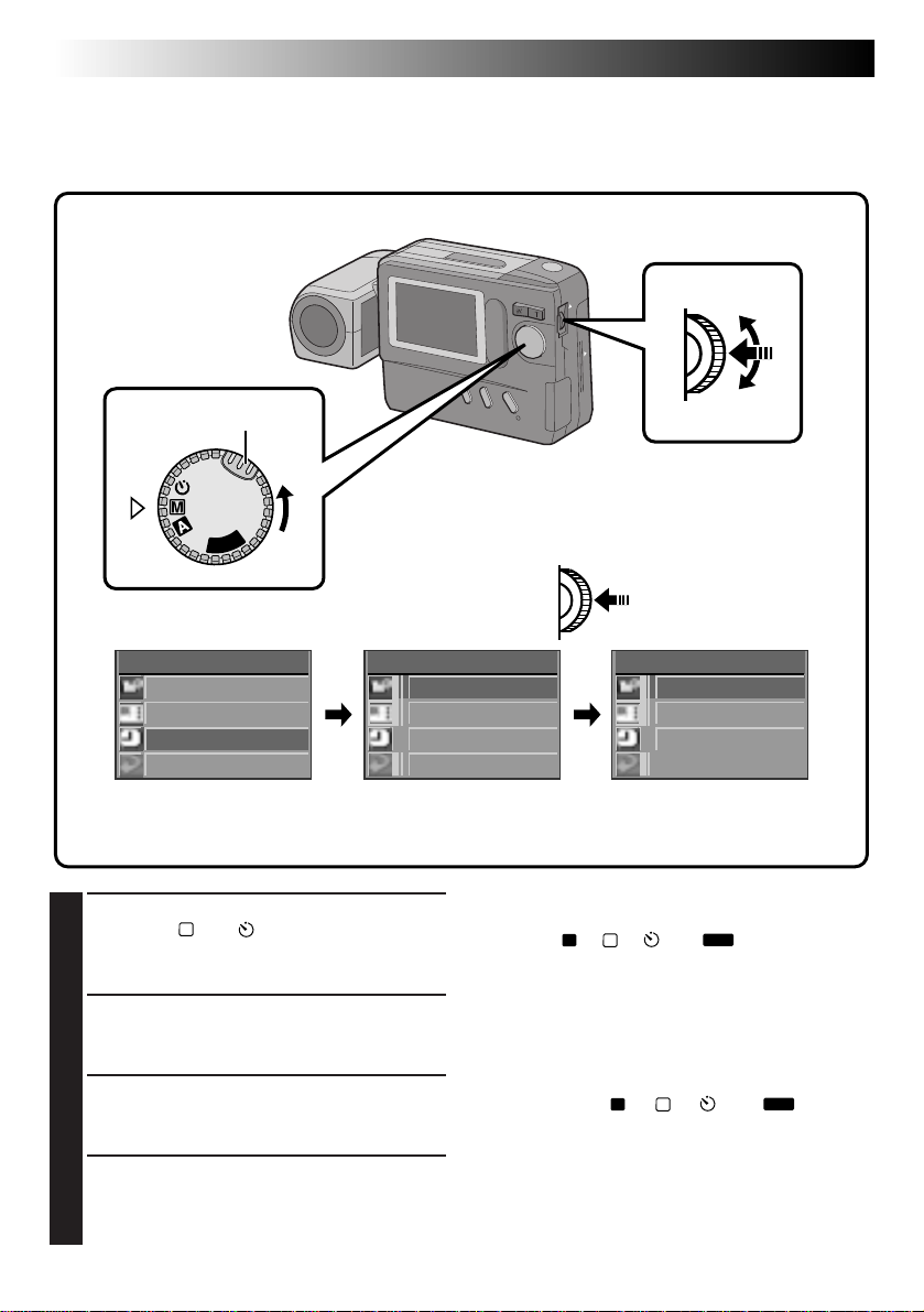
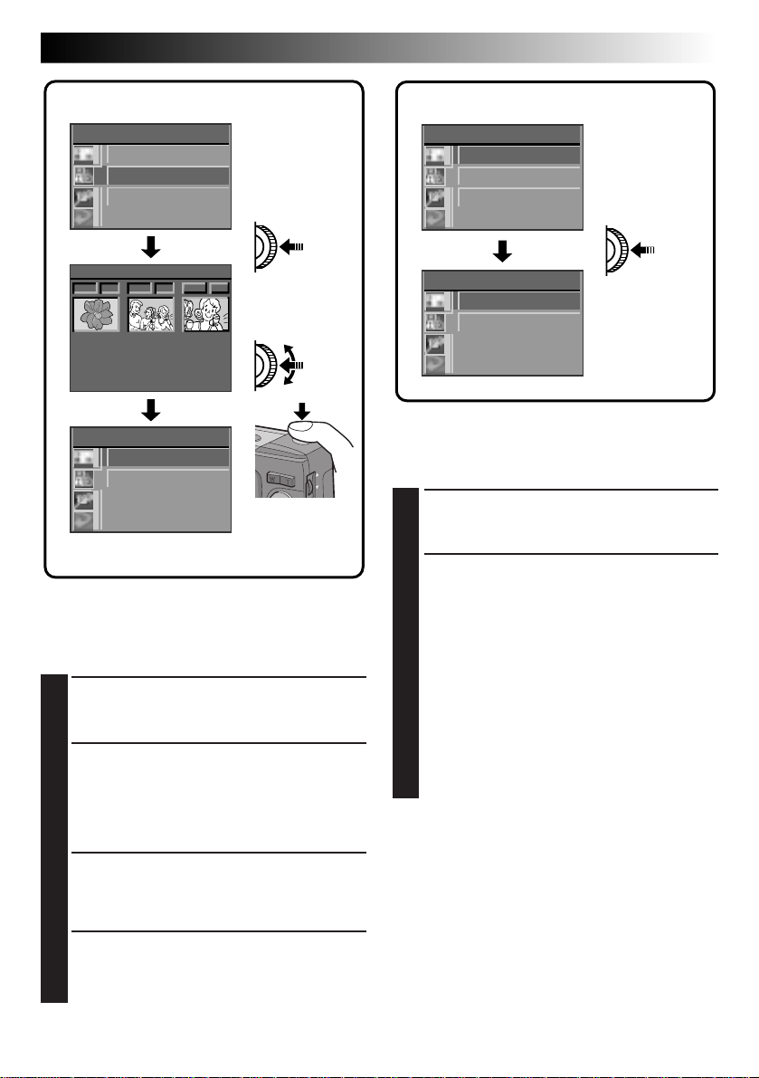
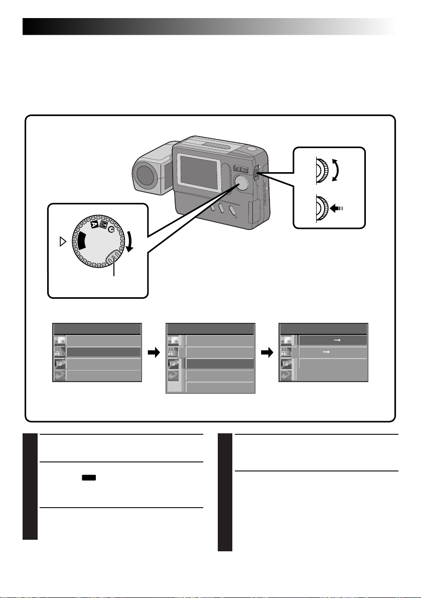
Pictrue Mode Selection
The Picture Quality mode can be selected to best match your needs. Three Picture Quality modes are
available: FINE, STD (standard) and ECONOMY (in order of quality).
MENU Jog Dial
Power Dial
Lock Button
LCD monitor
P
L
A
Y
OFF
Turn the Power Dial, while pressing its Lock
1
Button, to “M” and push the MENU Jog Dial.
•The CAMERA MENU Screen appears.
Rotate the MENU Jog Dial to select “PICTURE
2
MODE” and push it.
•The PICTURE MODE Screen appears.
Rotate the MENU Jog Dial to select the
3
“FINE”, “STD” or “ECONOMY” Picture
Quality mode and push it.
•The Picture Quality mode is set, and the
CAMERA MENU Screen appears.
Push the MENU Jog Dial.
4
•The shooting screen reappears.
PICTURE QUALITY
MODE
FINE
STANDARD (STD)
ECONOMY
Number of Storable Images
(in Built-in Memory)
Approx. 30
Approx. 50
Approx. 100
CAMERA MENU
CAMERA
P ICTURE MODE
SYSTEM
EX I T
CAMERA MENU Screen PICTURE MODE Screen
P ICTURE MODE
F I NE
STD
ECON OMY
EX I T
NOTES:
●
The number of storable images depends on the
selected Picture Quality mode, the conditions
under which the camera is used, the temperature
during use of the camera and the batteries being
used.
●
The selected Picture Quality mode is used even
when the Power Dial is turned to positions other
than “M”.
Page 16
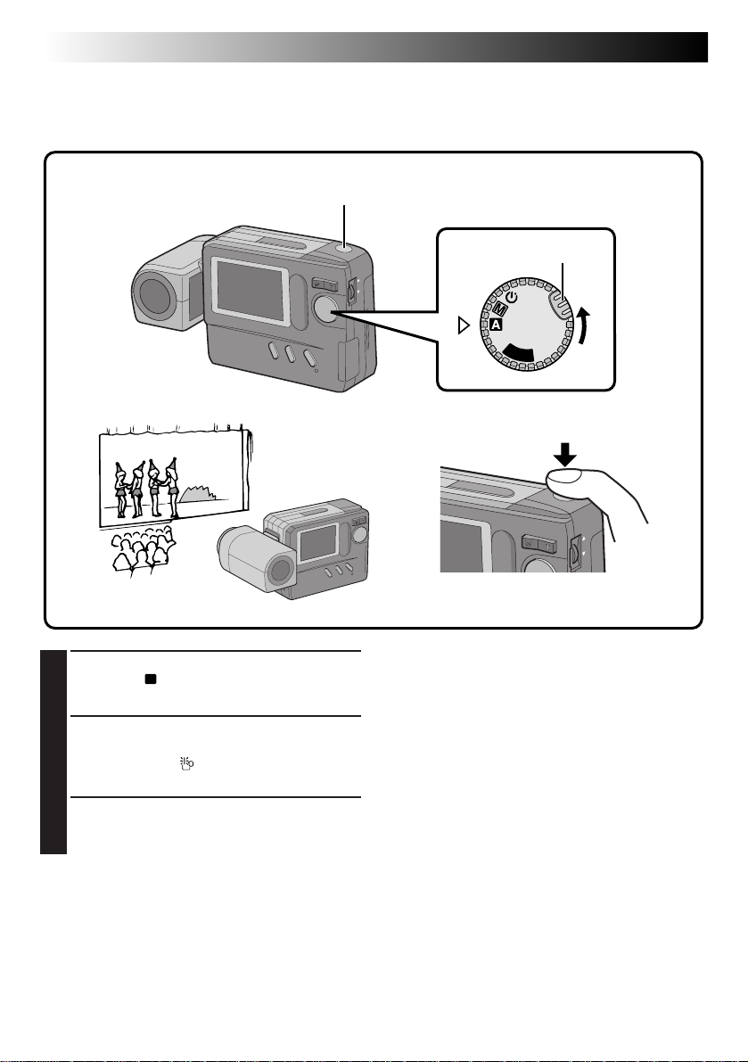
16 EN
BASIC OPERATION
(cont.)
Simple Shooting (Full Auto Shooting)
In the Full Auto mode, the camera controls focusing, shutter speed, exposure and white balance automatically to make your shooting simple and easy.
Shutter Release Button
Turn the Power Dial, while pressing its Lock
1
Button, to “A”.
•The camera turns on in the Full Auto mode.
Train the lens on the subject to be photo-
2
graphed.
•If the low light “ ” icon appears on the LCD
monitor, use the flash (Z pg. 20).
Press the Shutter Release Button.
3
•The image will be stored in the built-in
memory or Compact Flash card.
Power Dial
Lock Button
OFF
Y
A
P
L
NOTES:
●
When the Shutter Release Button is half-pressed,
auto focusing is performed.
●
After storing images in the built-in memory, it is
recommended that you transfer them to a
Compact Flash card or PC.
Page 17
EN 17
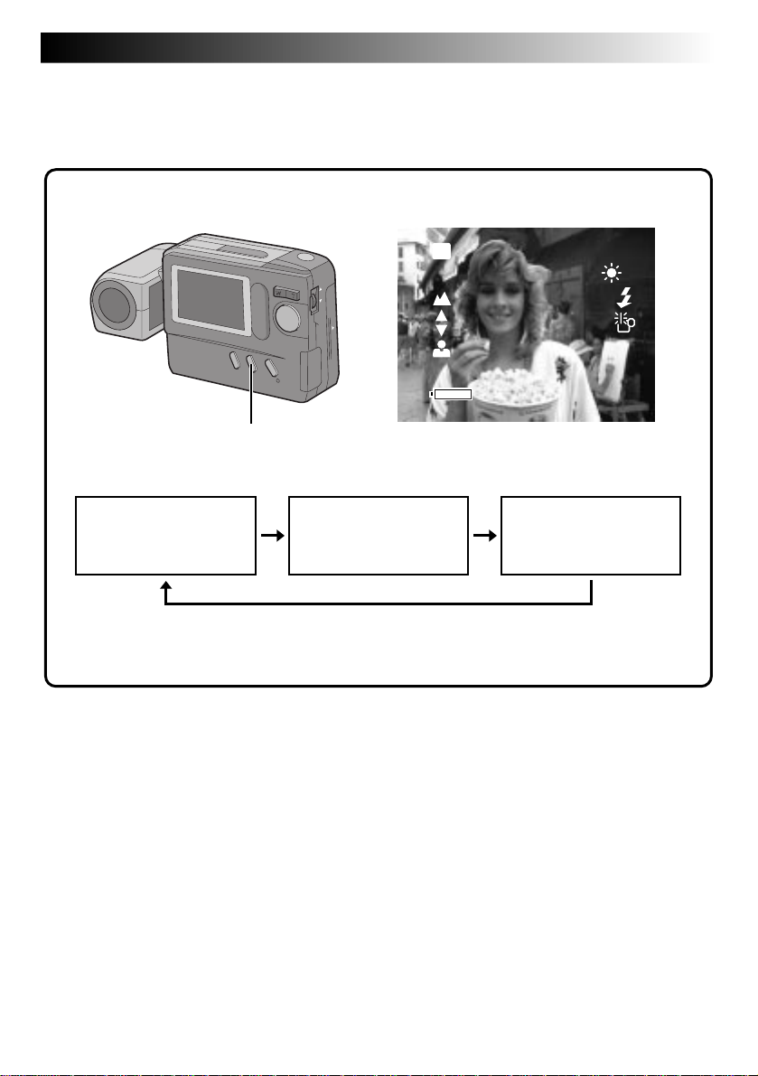
Camera Setup Check
Camera setup items that can be checked include the image storage location (only when stored in a Compact
Flash card), Picture Quality mode, number of shots taken, remaining battery power, date and time. For
details, see “On-Screen Display During Shooting” (Z pg. 57, 58).
LCD monitor
CF
FINE
+2
DISPLAY Button
Standard View mode
(colour display)
● Each press of the DISPLAY Button switches the View mode. The camera setup can be
checked in the Information Display Screen.
Standard View with
Information Display
mode (colour display)
Standard View with Information Display mode
021/ 030
0001/1
12. 1998
27.
4:05:23
1
Quick View mode
(monochrome display)
Page 18
18 EN
BASIC OPERATION
(cont.)
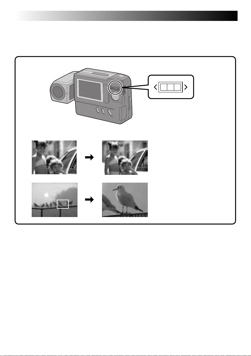
Zoom Shooting
The camera incorporates a 10X zooming function that corresponds to a 43 mm to 430 mm lens of a 35 mm
camera. Zooming allows you to shoot wide areas, as well as close-ups of subjects located far away, without
changing the shooting position.
W T
W (Wide-angle) zooming
A relatively wide area can be
photographed.
T (Telescopic) zooming
A faraway subject can be
magnified and photographed.
Page 19
EN 19
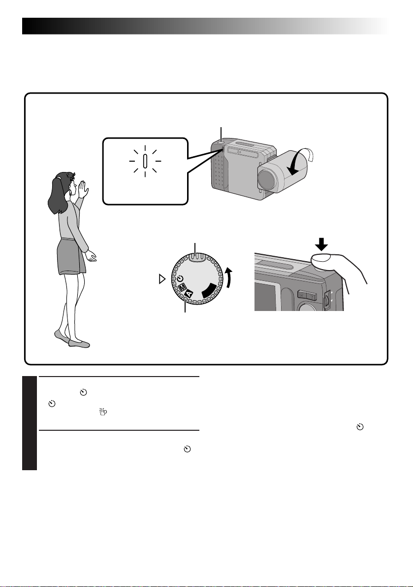
Self-Timer Shooting
When the Self-Timer is activated, the camera shutter is automatically released 15 seconds later. Once the
camera is set, the camera operator can become part of the scene. This function can also be used to prevent
blurring caused by subtle hand movements when the Shutter Release Button is pressed.
Self-Timer Lamp
Blinks.
Turn the Power Dial, while pressing its Lock
1
Button, to “ ”.
•“
” appears.
•If the low light “ ” icon appears on the LCD
monitor, use the flash (Z pg. 20).
Press the Shutter Release Button.
2
•The Self-Timer Lamp and the on-screen “ ”
icon start blinking, then the shutter is
released 15 seconds later.
Lock Button
A
Y
OFF
Power Dial
Shutter Release Button
P
L
NOTES:
●
The Self-Timer Lamp starts blinking faster when
there are 5 seconds or less remaining before the
shutter is released.
●
If you wish to cancel the Self-Timer half-way, turn
the Power Dial to any position except “ ”.
●
Focusing is performed when the Shutter Release
Button is pressed.
Page 20
20 EN
BASIC OPERATION
(cont.)
Flash Shooting
Use the flash when the low light “ ” icon appears on-screen during indoor shooting or under low light.
Flash
MENU Jog Dial
Power Dial
Lock Button
OFF
Y
A
P
L
FLASH/TRANSFER Button Flash Lamp
Make sure that the Power Dial is set to “A”,
1
“M” or “ ”, then press the FLASH/TRANSFER
Button.
•The Flash Lamp starts blinking and the flash
begins charging.
When charging is complete, the Flash Lamp
stops blinking but stays lit, and the flash “
icon appears on the LCD monitor.
•If no operation is performed while the flash
icon is displayed, the flash icon disappears.
When this occurs, press the FLASH/
TRANSFER Button again.
•To abort flash shooting before taking a
picture, press the FLASH/TRANSFER Button
again.
Aim the flash at the subject and press the
2
Shutter Release Button.
•The flash emits light and the Flash Lamp
turns off.
To take another shot with a flash . . .
.... repeat the above steps.
Flash Adjustment
The flash intensity can be increased or decreased by
2 steps. For details, see “Flash Adjustment”
(Z pg. 29).
”
NOTES:
●
While the flash is charging, the LCD monitor turns
off to save power. This is not a malfunction. Once
the flash is charged after a few seconds, the LCD
monitor turns on again.
●
When the batteries are nearly exhausted during
flash shooting, the power may turn off.
●
During Self-Recording, the flash is not charged
and does not emit light.
●
Since flash shooting consumes a large amount of
battery power, it is recommended to keep a spare
set of batteries nearby when you are planning to
take many photographs with the flash.
●
When battery power weakens, the time it takes for
the Flash Lamp to light steadily increases, and
flash charging may be aborted. Before pressing
the Shutter Release Button, make sure the Flash
Lamp stays lit.
Page 21
MANUAL SHOOTING
EN 21
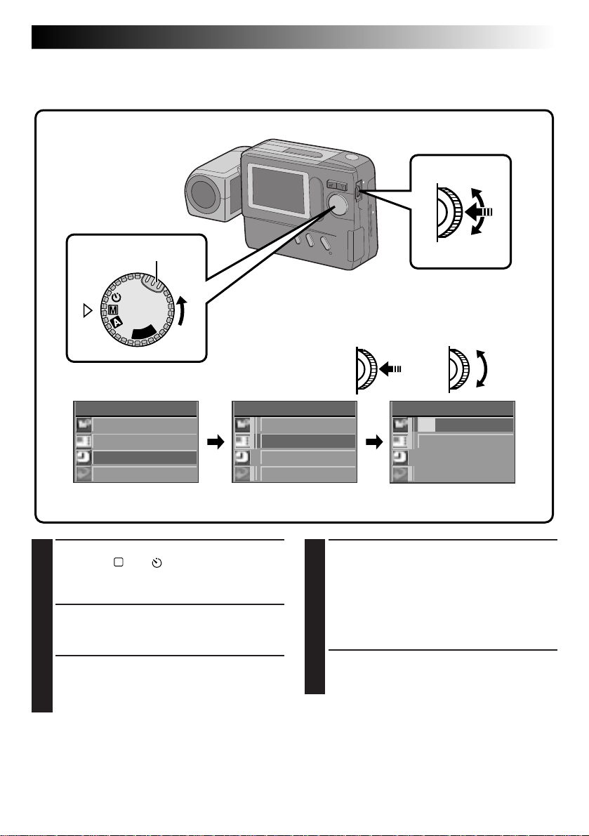
Exposure Control
When the subject appears too dark or too bright on the LCD monitor, it may be necessary to compensate for
the ambient brightness. This will make it possible to capture the contours of the dark and bright regions of
the image more clearly.
NOTE:
Use the flash when the low light “ ” icon appears.
Power Dial
Lock button
P
L
A
Y
OFF
LCD monitor
CAMERA MENU
CAMERA
P ICTURE MODE
SYSTEM
EX I T
CAMERA MENU Screen
Turn the Power Dial, while pressing its Lock
1
Button, to “M” or “ ” and push the MENU
Jog Dial.
•The CAMERA MENU Screen appears.
Rotate the MENU Jog Dial to select
2
“CAMERA” and push it.
•The CAMERA Setup Screen appears.
Rotate the MENU Jog Dial to select
3
“EXPOSURE” and push it.
•The EXPOSURE Setup Screen appears.
Rotate the MENU Jog Dial to select the
4
current value and push it.
•The item colour changes to indicate that
setting is possible.
CAMERA
EXPOSURE 0
M.W. B . AUTO
SHUTTER
SPEED UTOA
EX I T
CAMERA Setup Screen
Rotate the MENU Jog Dial to adjust the
5
exposure.
•The exposure value can be selected from –6
and +6.
To brighten the image:
Increase the exposure value. (maximum +6)
To darken the image:
Decrease the exposure value. (maximum –6)
Push the MENU Jog Dial twice.
6
•The EXPOSURE Setup Screen disappears.
•The exposure value is set and the shooting
screen reappears.
To adjust a previously set exposure value . . .
.... repeat the above procedure from step 1.
NOTE:
To set the exposure value to the standard level, set
the exposure value to “0” or turn the Power Dial to
“ A”.
MENU Jog Dial
To darken the image
To brighten the image
EXPOSURE
+6
EX I T
EXPOSURE Setup Screen
Page 22

22 EN
MANUAL SHOOTING
(cont.)
White Balance Control
Adjusting the White Balance
If the image appears greenish, reddish or bluish, it may be necessary to adjust the white balance of the
camera. From the list of presets (“ ”, “ ” or “ ”), select the one that makes the colours in the image look
the most natural. If the colours appear only slightly unnatural, select “AUTO”.
MENU Jog DialPower Dial
Lock Button
P
L
A
Y
OFF
LCD monitor
CAMERA MENU
CAMERA
P ICTURE MODE
SYSTEM
EX I T
CAMERA MENU Screen
CAMERA
EXPOSURE 0
M.W. B . AUTO
SHUTTER
SPEED UTOA
EX I T
CAMERA Setup Screen
M.W. B .
AUTO
MW
B
EX I T
M.W.B. Setup Screen
Turn the Power Dial, while pressing its Lock
1
Button, to “M” or “ ” and push the MENU
Jog Dial.
•The CAMERA MENU Screen appears.
Rotate the MENU Jog Dial to select
2
“CAMERA” and push it.
•The CAMERA Setup Screen appears.
Rotate the MENU Jog Dial to select “M.W.B.”
3
(Manual White Balance) and push it.
•The M.W.B. Setup Screen appears.
NOTE:
If a satisfactory white balance cannot be obtained
with any of the “ ”, “ ”, “ ” or “AUTO”
positions, adjust the white balance manually as
indicated in “Adjusting the White Balance Manually” (Z pg. 23).
Rotate the MENU Jog Dial to select “ ”,
4
“ ”, “ ” or “AUTO” and push it.
•Select the preset that can provide the subject
with the most desirable white balance.
The following 5 options can be selected.
AUTO ...... Select this position to adjust the
MWB .......Select to photograph the subject
Push the MENU Jog Dial twice.
5
•The M.W.B. Setup Screen disappears and the
shooting screen reappears.
colour balance automatically.
When the Full Auto mode is
selected with the Power Dial, this
position is selected automatically.
............ Select for shooting outdoors on a
fine day.
...........Select for shooting on a cloudy day
or in the shade.
.............Select for shooting with in-
candescent lamps or video lighting,
etc.
with a previously adjusted colour
balance (Z pg. 23).
Page 23

EN 23
Adjusting the White Balance Manually (M.W.B.)
If none of the preset “ ”, “ ”, “ ” or “AUTO” positions can make the colours in the image look natural,
adjust the white balance manually to obtain the most suitable colour tones possible.
In step 4 on the previous page (Z pg. 22),
1
select “MWB”.
Place a sheet of white paper about 1 ft.
2
(30 cm) in front of the lens.
•Place it so that the white paper fills the
screen.
Push the MENU Jog Dial.
3
•The setting is completed after about 1
second.
•The setting can be redone by pushing the
MENU Jog Dial again.
Rotate the MENU Jog Dial to select “EXIT”
4
During indoor shooting . . .
.... the subject is exposed to a variety of light
sources, including outdoor light, fluorescent
light, candle light and so on. As the colour
temperatures of these light sources vary widely,
manual white balance adjustment is recommended if you want to shoot images with the
most natural colour tones possible.
When the white balance is adjusted using coloured
paper . . .
.... in step 2, you can shoot images with a different
colour tone than when white paper is used.
Example:
When red paper is used:
The colours will be blue-greenish.
When blue paper is used:
The colours will be amberish.
When yellow paper is used:
The colours will be purplish.
and push it 3 times.
•The M.W.B. Setup Screen disappears and the
shooting screen reappears.
To return a manually-set white balance to an
automatically-set white balance . . .
.... select “AUTO” in step 4 in the procedure on
page 22 or turn the Power Dial to “A”.
NOTE:
The manually-set white balance is held in memory
until another balance value is set by selecting
“M.W.B.”.
Page 24

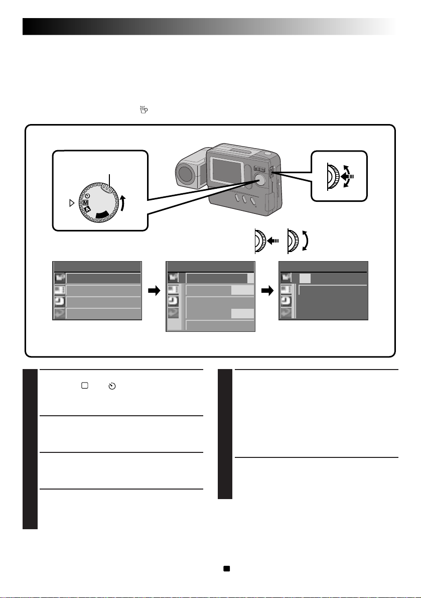
24 EN
MANUAL SHOOTING
(cont.)
Shutter Speeds Selection
Selecting the Shutter Speed
The shutter speed of the camera can be selected manually, allowing a variety of expression in your pictures.
MENU Jog Dial
Power Dial
Look Button
P
L
A
Y
OFF
LCD monitor
CAMERA MENU
CAMERA
P ICTURE MODE
SYSTEM
EX I T
CAMERA MENU Screen
CAMERA
EXPOSURE 0
M.W. B . AUTO
SHUTTER
SPEED AUTO
EX I T
SHUTTER SPEED Setup ScreenCAMERA Setup Screen
UTTERHS SPEED
AUTO 1 / 100
1 /
1 / 6
25 0
1 / 1 3 1 / 5 00
1 / 2 5 1 / 1 000
EX I T
Turn the Power Dial, while pressing its Lock
1
Button, to “M” or “ ” and push the MENU
Jog Dial.
•The CAMERA MENU Screen appears.
Rotate the MENU Jog Dial to select
2
“CAMERA” and push it.
•The CAMERA Setup Screen appears.
Rotate the MENU Jog Dial to select
3
“SHUTTER SPEED” and push it.
•The SHUTTER SPEED Setup Screen appears.
Rotate the MENU Jog Dial to select the
4
desired shutter speed and push it twice.
•The shutter speed is selected and the
shooting screen reappears.
NOTE:
When you select a shutter speed of 1/13 sec. or less
(or 1/25 sec. or less when performing zoom or
close-up shooting), it is recommended that you use
a tripod to prevent blurring.
Page 25

Shutter Speeds and Effects
EN 25
Shutter Speed
AUTO
1/6 (sec.)
1/13 (sec.)
1/25 (sec.)
1/100 (sec.)
1/250 (sec.)
1/500 (sec.)
1/1000 (sec.)
Automatically selects a shutter speed according to the subject lighting.
Suitable for shooting night views. Lights from moving cars, etc. are photographed with
motion streaks. Use a tripod to avoid blurring caused by subtle hand movements.
Suitable for shooting in darkly lit environments. A slow shutter speed can collect more
light in the camera than usual, and shoot bright, clear images of hard-to-shoot subjects
in low light. Use a tripod to avoid blurring caused by subtle hand movements.
Suitable for shooting in dimly lit environments (eg. rainy day). A slow shutter speed
can collect more light in the camera than usual, and shoot bright, clear images of
hard-to-shoot subjects in low light.
Suitable for shooting under outdoor lighting conditions such as a cloudy day.
Suitable for shooting under outdoor lighting conditions such as a sunny day. This
shutter speed is not affected by subtle hand movements.
Suitable for shooting under outdoor lighting conditions such as by the seashore on a
sunny day. This shutter speed is not affected by subtle hand movements.
Allows fast-moving images to be captured one frame at a time. Use this shutter speed
under good lighting conditions.
Effect
NOTE:
If a high shutter speed is used under fluorescent lighting, hunting may occur in the image or the image
colour may be changed. This is not a malfunction.
Page 26
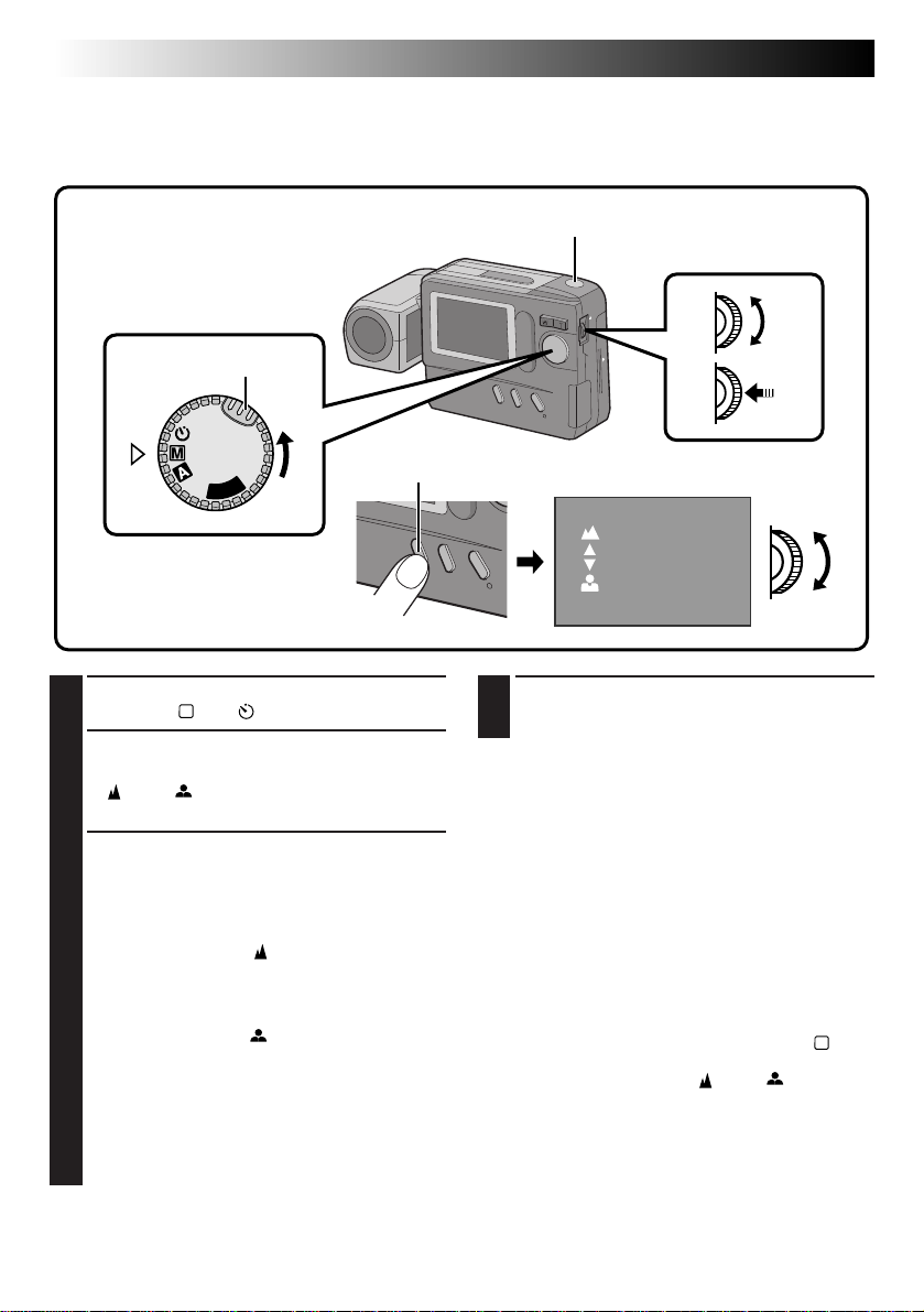
26 EN
MANUAL SHOOTING
(cont.)
Manual Focusing
In contrast to auto focusing, where the camera automatically focuses on the subject, manual focusing can be
used when you want to intentionally change the point of focus in an image.
Power Dial
Lock Button
P
L
A
Y
OFF
Turn the Power Dial, while pressing its Lock
1
Button, to “M” or “ ”.
Press and hold the CLEAR/FOCUS Button for
2
about 2 seconds.
•“ ” and “ ” appear, and the focus can be
adjusted manually.
Rotate the FOCUS Dial (MENU Jog Dial) to
3
focus the subject.
To focus on a farther subject . . .
Rotate the FOCUS Dial (MENU Jog Dial)
upward. When the focus level cannot be
adjusted any further, “ ” starts to blink.
To focus on a nearer subject . . .
Rotate the FOCUS Dial (MENU Jog Dial)
downward. When the focus level cannot be
adjusted any closer, “ ” starts to blink.
•2 focusing speeds are available. They can be
selected depending on how fast the FOCUS
Dial (MENU Jog Dial) is rotated. If the
FOCUS Dial (MENU Jog Dial) is rotated
quickly, the focus changes drastically. If the
FOCUS Dial (MENU Jog Dial) is rotated
slowly, the focus changes gradually.
Shutter Release Button
CLEAR/FOCUS Button
4
NOTE:
Manual focusing is recommended in the following
cases:
●
When shooting a subject with low contrast
(variation in brightness/darkness), for example a
flat wall or blue sky.
●
When there is an obstacle such as a mesh
between the camera and the subject.
●
When the subject consists of a regular arrangement of fine patterns or similar patterns.
●
When shooting under a flickering light source
such as a fluorescent lamp.
To use auto focusing in the Manual mode (“M”) . . .
.... press and hold the CLEAR/FOCUS Button for
about 2 seconds so that “ ” and “ ” disappear.
Minimum subject distance:
The closest that this camera can focus on a subject,
with the zoom set all the way to “W”, is 7 cm.
FOCUS Dial
(MENU Jog dial)
LCD monitor
Press the Shutter Release Button to shoot the
image.
Page 27
EN 27
View Mode Selection
The Standard View mode displays a colour image on the LCD monitor, while the Quick View mode displays
a black-and-white image, but updates it more quickly to show the actual motion of the subject more
faithfully.
Power Dial
Lock Button
OFF
Y
A
P
L
DISPLAY Button
Make sure that the Power Dial is set to “M”, “A” or “ ”, then press the DISPLAY Button.
1
•Each press of the DISPLAY Button switches the screen as shown below.
Standard View mode
(colour display)
Standard View with
Information Display
mode (colour display)
Standard View mode
A colour image is displayed on the LCD monitor
and is updated about 4 times a second. This mode
is suitable for shooting stationary subjects.
Quick View mode
(monochrome display)
Quick View mode
A black-and-white image is displayed on the LCD
monitor and is updated about 15 times a second.
This mode is suitable for shooting moving subjects.
• The image is stored in colour.
• The on-screen display is not available.
• When the shutter speed is set to 1/6 sec. or 1/13
sec., the Quick View mode is not available.
Page 28
28 EN
MANUAL SHOOTING
(cont.)
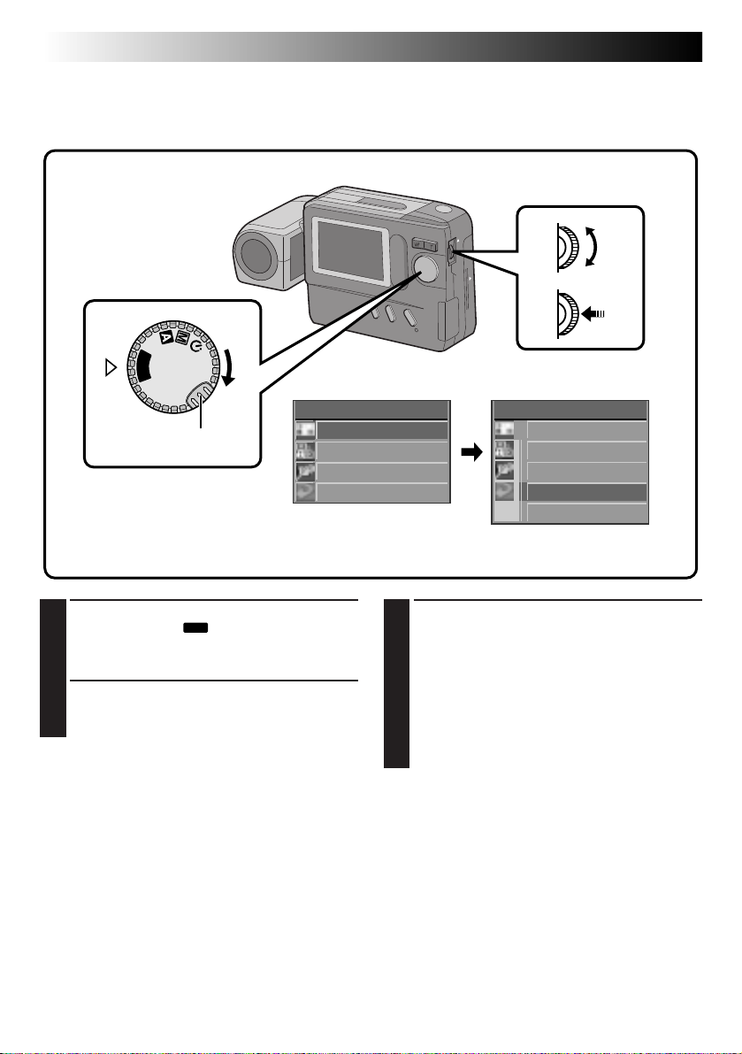
Power Save Mode
The Power Save mode switches the camera automatically off when no operation has been performed for
more than 2 minutes.
MENU Jog Dial
Power Dial
Lock Button
P
L
A
Y
OFF
LCD monitor
CAMERA MENU
CAMERA
P ICTURE MODE
SYSTEM
EX I T
CAMERA MENU Screen SYSTEM Setup Screen POWER SAVE Screen
Turn the Power Dial, while pressing its Lock
1
Button, to “M” or “ ” and push the MENU
Jog Dial.
•The CAMERA MENU Screen appears.
Rotate the MENU Jog Dial to select “SYSTEM”
2
and push it.
•The SYSTEM Setup Screen appears.
Rotate the MENU Jog Dial to select “POWER
3
SAVE” and push it.
•The POWER SAVE Screen appears.
Rotate the MENU Jog Dial to select “ON” and
4
push it twice.
•The shooting screen reappears and the Power
Save mode is activated.
SYSTEM
POWER SAVE
FLASH ADJ .
DATE / T IME
EX I T
To deactivate the Power Save mode . . .
.... select “OFF” in step 4. When the Power Dial is
set to “A”, “M”, “ ” or “
power will stay on, even when no operations
are performed.
NOTES:
●
To switch the camera on again after it has been
switched off by the Power Save mode, turn the
Power Dial to “OFF”, wait for more than 1 second,
then turn it to “ A”, “ M”, “ ” or “
●
Do not forget to switch the camera off when not
in use, so that the batteries do not become
prematurely exhausted.
●
The Power Save mode is factory-preset to “ON”.
POWER SAVE
ON
OFF
EX I T
”, the camera
PLAY
PLAY
”.
Page 29
EN 29
Flash Adjustment
If an image shot with the flash is too dark or too bright, adjust the flash intensity as described below.
MENU Jog Dial
Power Dial
Lock Button
P
L
A
Y
OFF
LCD monitor
CAMERA MENU
CAMERA
P ICTURE MODE
SYSTEM
EX I T
Turn the Power Dial, while pressing its Lock
1
Button, to “M” or “ ” and push the MENU
Jog Dial.
•The CAMERA MENU Screen appears.
Rotate the MENU Jog Dial to select “SYSTEM”
2
and push it.
•The SYSTEM Setup Screen appears.
Rotate the MENU Jog Dial to select “FLASH
3
ADJ.” and push it.
•The FLASH ADJ. (Adjustment) Screen
appears.
SYSTEM
POWER SAVE
FLASH ADJ .
DATE / T IME
EX I T
SYSTEM Setup Screen FLASH ADJ. (Adjustment) ScreenCAMERA MENU Screen
FLASH ADJ .
+2
EX I T
Rotate the MENU Jog Dial to select the flash
4
intensity and push it.
•Select from “0”, “–1”, “–2”, “+1” and “+2”.
To brighten the flash (+1, +2) . . .
Rotate the MENU Jog Dial downward.
To darken the flash (–1, –2) . . .
Rotate the MENU Jog Dial upward.
Push the MENU Jog Dial twice.
5
•The flash adjustment value is entered and the
shooting screen reappears.
NOTES:
●
Aim the flash at the subject.
●
Even when the flash intensity is increased, the
subject may not be properly lit, depending on the
shooting conditions.
Page 30
30 EN
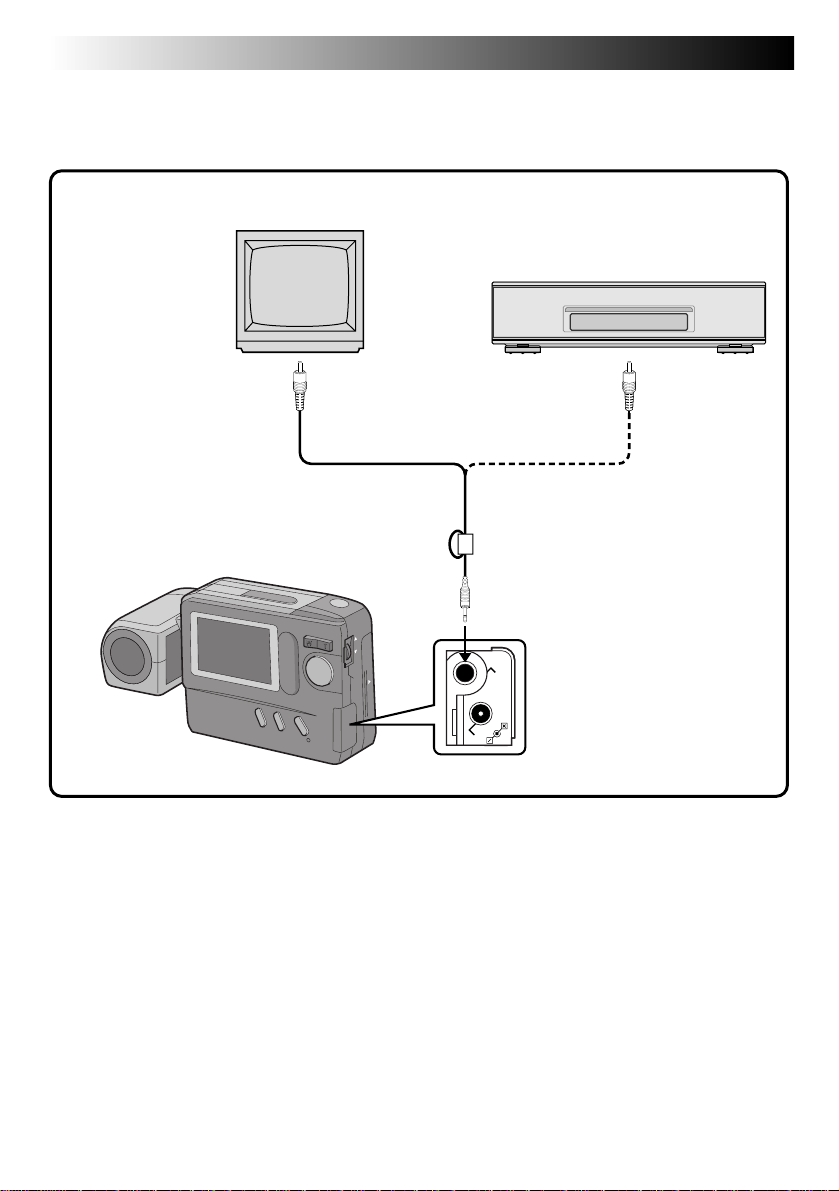
PLAYBACK
Playback Through a TV Monitor or VCR
By connecting the digital still camera to a TV monitor or VCR and starting playback, images can be
monitored on the TV screen or recorded onto a videotape.
TV
VCR
To VIDEO IN To VIDEO IN
Video cable
(provided)
Digital Still Camera
Core filter
To VIDEO OUT
VIDEO OUT
DC-IN
NOTES:
●
For connections to a TV monitor or VCR, refer to their instruction manuals.
●
The playback image can also be viewed on the LCD monitor of the camera without connecting it to a TV
monitor or VCR.
●
During playback on a TV monitor, indications displayed in any of the shooting modes do not appear.
Page 31
Normal Playback
Images shot with the camera are automatically
numbered, then stored in numerical order. You can
view the stored images, one at a time, much like
flipping through a photo album.
EN 31
Auto Playback
You can run through all the images stored in
memory automatically. This is like a regular slideshow.
Zoom Button
W T
Power Dial
OFF
Y
A
L
P
Lock Button
Turn the Power Dial, while pressing its Lock
1
Button, to “
•The most recently photographed image is
displayed.
•If there are no images in memory, a blue
background is displayed on the screen.
When there is more than one image in
2
memory:
Press the Zoom Button to view other images.
“T” : Displays the next image.
“W” : Displays the previous image.
PLAY
”.
NOTE:
Even if you shoot a new image after playing back a
low-numbered one, this will not overwrite an
existing image, because new images are automatically stored after the last-recorded one.
Turn the Power Dial, while pressing its Lock
1
Button, to “
•The most recently photographed image is
displayed.
Press and hold the Zoom Button for more than
2
3 seconds.
“T” : Displays images in ascending order.
“W” : Displays images in descending order.
Press the Zoom Button to stop Auto Playback.
3
•Auto Playback can be stopped by pressing
either “T” or “W”.
PLAY
”.
Page 32

32 EN
PLAYBACK
INDEX Screen
The images you shot can be displayed together with their index information. Convenient for checking
images shot beforehand, the INDEX Screen also shows the Picture Quality mode as well as which images
are protected against accidental erasure.
Selected image
INDEX
Index number
001 F 002 S 003 E
Picture Quality mode
(cont.)
004 F
001 to 999: Index number
Since this camera can store up to 999 images using
a Compact Flash card, the index numbers range
from 001 to 999. For example, when 10 images are
stored (index number: 001 to 010), if three images
with index numbers 002, 004 and 006 are deleted
from memory, the remaining images are automatically moved up to fill any gaps in the numerical
sequence. Therefore, the number of remaining
images is 7, and the new index numbers range from
001 to 007.
When images are stored in both the built-in
memory and a Compact Flash card installed in the
camera, their index images and numbers are
different from those stored using only the built-in
memory.
005 F
006 F
F/S/E: Picture Quality mode
Displays the Picture Quality mode of the stored
image. There are 3 modes available: Fine (“F”),
Standard (“S”) and Economy (“E”) (in order of
quality).
: Protect icon
When an image is protected against its accidental
erasure, a padlock mark appears next to it, and that
image cannot be deleted.
Selected Image
An image is framed like this when it is selected.
Rotate the MENU Jog Dial to move the green frame
to the desired image.
Protect icon
Page 33

EN 33
Index Playback
You can view all images stored in memory six at a time. Use this mode when looking for a image you wish
to view.
Power Dial
OFF
Y
A
L
P
Lock Button
LCD monitor
PLAY MENU
PLAY MODE
FI LE
CO
MM
. MODE
EX I T
PLAY MENU Screen
Turn the Power Dial, while pressing its Lock
1
Button, to “
Dial.
•The PLAY MENU Screen appears.
Rotate the MENU Jog Dial to select “PLAY
2
MODE” and push it.
•The PLAY MODE Screen appears.
Rotate the MENU Jog Dial to select “INDEX”
3
and push it.
•The INDEX Screen appears.
Rotate the MENU Jog Dial to select the image
4
to be displayed and push it.
•The image selected in the INDEX Screen is
displayed.
” and push the MENU Jog
PLAY
PLAY MODE
I NDEX
EFFECT
FRAME
MULT I
EX I T
PLAY MODE Screen
NOTE:
If no images are stored in memory, “PLAY MODE”
cannot be selected.
MENU Jog Dial
INDEX
00 1 F 002 S 00 3 E
00 4 F
00 5 F
INDEX Screen
006 F
Page 34

34 EN
PLAYBACK
Protecting Images
The Protect mode helps prevent the accidental erasure of images. Put a padlock mark next to the desired
image, and that image cannot be deleted.
MENU Jog Dial
Power Dial
OFF
Y
A
L
P
Lock Button
LCD monitor
PLAY MENU
PLAY MODE
F I LE
CO
MM
. MODE
EX I T
PLAY MENU Screen
F I LE
PROTECT
DELETE
COPY
FOR MAT
EX I T
FILE Setup Screen
(cont.)
Turn the Power Dial, while pressing its Lock
1
Button, to “
Dial.
•The PLAY MENU Screen appears.
Rotate the MENU Jog Dial to select “FILE”
2
and push it.
•The FILE Setup Screen appears.
Rotate the MENU Jog Dial to select
3
“PROTECT” and push it.
•The PROTECT Screen appears.
PLAY
” and push the MENU Jog
NOTE:
When the camera’s memory is initialized, even
protected images are deleted. If you do not want to
lose important images, transfer them to a PC and
save them.
Page 35

INDEX
00 1 F 002 S 0 03 E
PRESS SHUTTER
AFTER SELECT
PROTECT Screen
EN 35
Rotate the MENU Jog Dial to select the image
4
to be protected (against accidental erasure)
and push it
•A padlock mark appears on the selected
image to indicate that it is protected.
•Protect each image that you do not want to
delete by accident.
Press the Shutter Release Button.
5
Push the MENU Jog Dial twice.
6
•The screen returns to the normal playback
screen.
To remove protection . . .
Perform steps 1 through 3, then rotate the MENU
Jog Dial to select the desired padlocked image and
push it. The padlock mark located above the image
disappears and the image is no longer protected.
When finished unprotecting images, perform steps 5
and 6.
Page 36

36 EN
Deleting Images
Previously shot images can be deleted either one at a time or all at once.
Power Dial
OFF
Y
A
L
P
Lock Button
LCD monitor
PLAY MENU
PLAY MODE
F I LE
CO
MM
. MODE
EX I T
PLAY MENU Screen
PLAYBACK
MENU Jog Dial
F I LE
PROTECT
DELETE
COPY
FOR MAT
EX I T
FILE Screen
(cont.)
Turn the Power Dial, while pressing its Lock
1
Button, to “
Dial.
•The PLAY MENU Screen appears.
Rotate the MENU Jog Dial to select “FILE”
2
and push it.
•The FILE Screen appears.
PLAY
” and push the MENU Jog
Rotate the MENU Jog Dial to select “DELETE”
3
and push it.
•The DELETE Screen appears.
Page 37
EN 37
LCD monitor
DELETE
DELETE Screen
ALL
SELECTED
EXI T
DELETE
001 F 002 S 003 E
Delete Select
Screen
PRESS SHUTT ER
AFT ER SELECT
DELETE
EXECUT E
EXI T
Deletion Confirmation Screen
To select an image by browsing images
stored in memory . . .
Before doing the following, perform steps 1 through
3 (Z pg. 36).
Rotate the MENU Jog Dial to select
4
“SELECTED” and push it.
•The Delete Select Screen appears.
Rotate the MENU Jog Dial to select an image
5
to be deleted, and push it.
•“x” appears above the selected image.
•To abort deletion of a selected image, push the
MENU Jog Dial again. The “x” mark indicating
that the image is to be deleted disappears.
Press the Shutter Release Button.
6
•The Deletion Confirmation Screen appears.
• If you want to abort deletion now, rotate the MENU
Jog Dial to select “EXIT” and push it 4 times.
Rotate the MENU Jog Dial to select
7
“EXECUTE” and push it.
•The selected images are deleted and the normal
playback screen reappears.
LCD monitor
DELETE
DELETE Screen
ALL
SELECTED
EXI T
DELETE
EXECUT E
EXI T
To delete all images . . .
Before doing the following, perform steps 1 through
3 (
Z pg. 36).
Rotate the MENU Jog Dial to select “ALL” and
4
push it.
•The Deletion Confirmation Screen appears.
Rotate the MENU Jog Dial to select “EX-
5
ECUTE” and push it.
•“DELETING IN PROGRESS” is displayed until
all images have been deleted, which can take
from a few seconds to several minutes,
depending on the number of images stored.
•If “CONTAINS PROTECTED IMAGES” is
displayed, only the unprotected images will be
deleted.
•When you also want to delete protected images,
unprotect them by referring to “To remove
protection” (Z pg. 35) before deleting all the
images.
•If you do not want to delete the images, rotate
the MENU Jog Dial to “EXIT” and push it 4
times to return to the normal playback screen.
Deletion
Confirmation
Screen
CAUTION
While protecting/unprotecting images, never remove
the Compact Flash card or disconnect power, as this
may cause the camera's built-in memory to be
corrupted. Also, be sure to use the optional AC power
adapter, as a malfunction may occur if the batteries
become exhausted halfway through the operation.
NOTES:
●
A deleted image is lost forever. To prevent accidental
deletion of important images, it is recommended that
you protect them or copy them to your PC.
●
If no images are stored in memory, “DELETE” cannot
be selected.
Page 38

38 EN
Applying Sepia/Black-and-White Effects
A sepia or black-and-white effect can be applied to a previously shot image.
Power Dial
OFF
Y
A
L
P
Lock Button
LCD monitor
PLAY MENU
PLAY MODE
F I LE
CO
MM
. MODE
EX I T
PLAY MENU Screen
PLAY MODE
I NDEX
EFFECT
FRAME
M ULT I
EX I T
PLAY MODE Screen
PLAYBACK
MENU Jog Dial
EFFECT
BLACK/WH ITE
SEP I A
ZOOM
EX I T
EFFECT Setup Screen
(cont.)
Turn the Power Dial, while pressing its Lock
1
Button, to “
Dial.
•The PLAY MENU Screen appears.
Rotate the MENU Jog Dial to select “PLAY
2
MODE” and push it.
•The PLAY MODE Screen appears.
Rotate the MENU Jog Dial to select “EFFECT”
3
and push it.
•The EFFECT Setup Screen appears.
” and push the MENU Jog
PLAY
Rotate the MENU Jog Dial to select “BLACK/
4
WHITE” or “SEPIA” and push it.
•The image is displayed with the black-andwhite or sepia effect applied to it.
•The effect is applied to other displayed
images until it is canceled.
To cancel the effect . . .
.... press the CLEAR/FOCUS Button.
Page 39

Magnifying the Playback Image (Zoom)
The zoom-in effect magnifies a selected area of image.
EN 39
Power Dial
OFF
Y
A
L
P
Lock Button
LCD monitor
PLAY MENU
PLAY MODE
F I LE
CO
MM
. MODE
EX I T
PLAY MENU Screen
Turn the Power Dial, while pressing its Lock
1
Button, to “
Dial.
•The PLAY MENU Screen appears.
Rotate the MENU Jog Dial to select “PLAY
2
MODE” and push it.
•The PLAY MODE Screen appears.
Rotate the MENU Jog Dial to select “EFFECT”
3
and push it.
•The EFFECT Setup Screen appears.
Rotate the MENU Jog Dial to select “ZOOM”
4
and push it.
PLAY
” and push the MENU Jog
PLAY MODE
I NDEX
EFFECT
FRAME
MULT I
EX I T
PLAY MODE Screen
Rotate the MENU Jog Dial to select the area
5
to be magnified, and push it.
•The selected image is split into 9 areas, from
•The effect is applied to other displayed
To cancel the effect . . .
.... press the CLEAR/FOCUS Button.
MENU Jog Dial
EFFECT
BLACK /WH ITE
SEP IA
ZOOM
EX I T
EFFECT Setup Screen
which you can select the area to be magnified. By rotating the MENU Jog Dial, you can
reach the desired area as indicated above.
images until it is canceled.
Page 40

40 EN
Types of Frames
An image can be displayed in 9 types of frames. The framed image can be printed out by transmitting the
image data with the frame data to a printer. Frames can also be used in 4-split or 16-split screens.
Preset frames (9 types)
PLAYBACK
(cont.)
Page 41

Framing an Image
Power Dial
OFF
Y
A
L
P
Lock Button
LCD monitor
PLAY MENU
PLAY MODE
F I LE
CO
MM
. MODE
EX I T
PLAY MENU Screen
EN 41
MENU Jog Dial
PLAY MODE
I NDEX
EFFECT
FRAME
MULT I
EX I T
FRAME Setup Screen
Turn the Power Dial, while pressing its Lock
1
Button, to “
Dial.
•The PLAY MENU Screen appears.
Rotate the MENU Jog Dial to select “PLAY
2
MODE” and push it.
•The PLAY MODE Screen appears.
Rotate the MENU Jog Dial to select “FRAME”
3
and push it.
•The FRAME Setup Screen appears.
Rotate the MENU Jog Dial to select a frame
4
and push it.
•The selected image is displayed inside the
frame.
PLAY
” and push the MENU Jog
NOTE:
Frames can also be used in 4-split or 16-split
screens (Z pg. 42).
To remove a frame . . .
.... press the CLEAR/FOCUS Button.
Page 42
42 EN
PLAYBACK
Multi-Image Screen
Multi-image screens that can be created are 4-split screens composed of the same image, 16-split screens
composed of the same image and 4-split screens composed of different, user-selected images.
MENU Jog Dial
Power Dial
OFF
Y
A
L
P
LCD monitor
(cont.)
Lock Button
Turn the Power Dial, while pressing its Lock
1
Button, to select “
Jog Dial.
•The PLAY MENU Screen appears.
Rotate the MENU Jog Dial to select “PLAY
2
MODE” and push it.
•The PLAY MODE Screen appears.
PLAY
” and push the MENU
PLAY MENU
PLAY MODE
F I LE
CO
MM
. MODE
EX I T
PLAY MENU Screen
Rotate the MENU Jog Dial to select “MULTI”
3
and push it.
•The MULTI Setup Screen appears.
•While a multi-image screen is being
PLAY MODE
I NDEX
EFFECT
FRAME
MULT I
EX I T
PLAY MODE Screen
displayed, it is impossible to select the
MULTI Setup Screen from the PLAY MODE
Screen. If you wish to select the MULTI Setup
Screen, first press the CLEAR/FOCUS Button
to return to the normal playback screen, then
perform steps 1 through 3.
Page 43
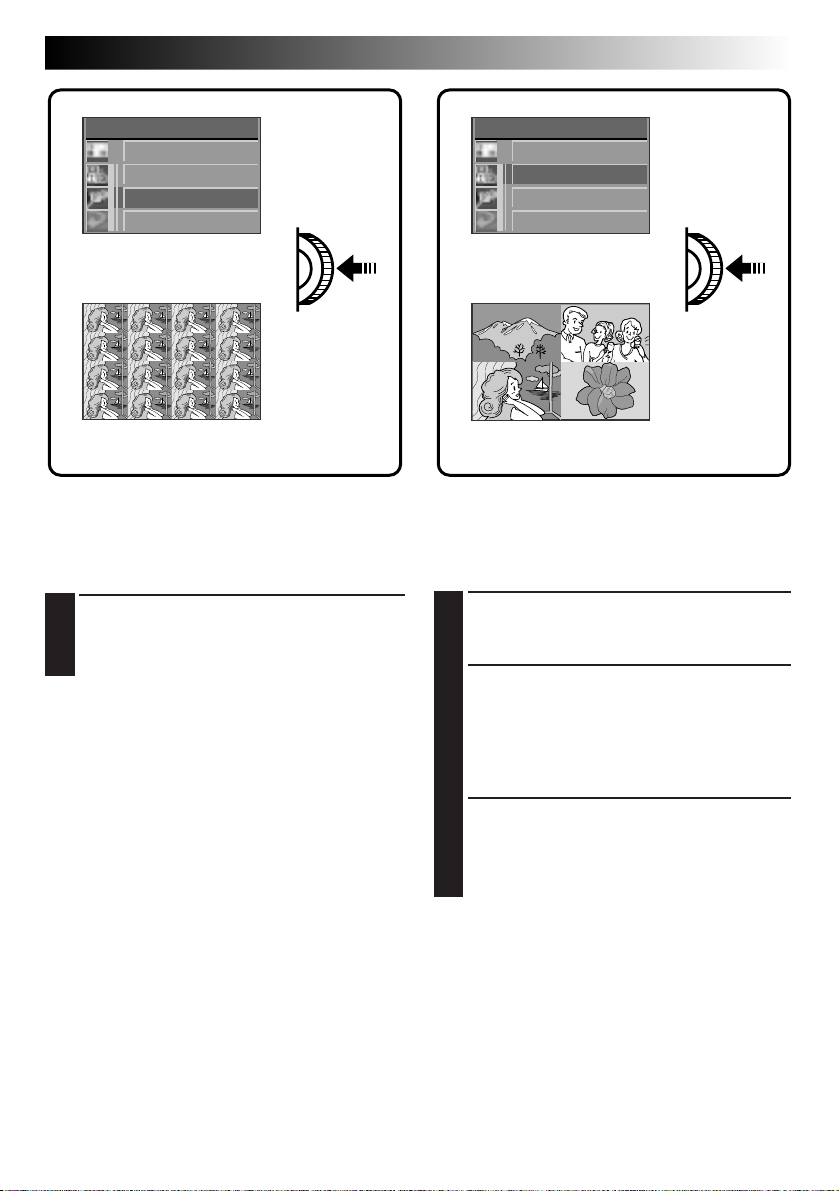
EN 43
MULT I
SAME 4
SELECTED 4
SAME 16
EXI T
MULTI Setup Sreen
Multi-image screen
To Create a Multi-Image Screen Using
the Same Image
Before doing the following, perform steps 1 through
3 (Z pg. 42).
Rotate the MENU Jog Dial to select “SAME 4”
4
or “SAME 16” and push it.
•A multi-image screen displaying 4 or 16 of
the same image appears.
NOTES:
●
By printing a multi-image screen to a printer that
supports sticker sheets, you can create stickers of
any image you like. For details, read the instruction manual of your printer.
●
To create a multi-image screen with frames, first
select a frame, referring to “Framing an image”
(Z pg. 41), then make a multi-image screen.
MULT I
SAME 4
SELECTED 4
SAME 16
EXI T
MULTI Setup Sreen
Multi-image screen
To Create a Multi-Image Screen Using
Selected Images
Before doing the following, perform steps 1 through
3 (Z pg. 42).
Rotate the MENU Jog Dial to select
4
“SELECTED 4” and push it.
•The MULTI Index Screen appears.
Rotate the MENU Jog Dial to select an image
5
and push it.
•“u” appears on the selected image.
To cancel the selection of an image . . .
... rotate the MENU Jog Dial to select the
image and push it. “u” disappears.
Repeat step 5 for all 4 images to be selected.
6
•The selected images are displayed in the
order they were selected in steps 5 and 6.
•A multi-image screen of the selected images
appears.
Page 44

44 EN
Compact Flash Card Operation
Installing a Compact Flash Card
A Compact Flash card increases the number images
that can be stored.
APPLIED OPERATIONS
Removing a Compact Flash Card
As a Compact Flash card retains images in its
memory even after it has been removed from the
camera, it can also be used as a medium for storing
images.
NOTES:
●
Switch the camera off with the Power Dial before
installing a Compact Flash card.
●
Point the marking on the bottom of the camera
and the one on the Compact Flash card upward,
then point the marking on the Compact Flash
card at the camera and install straight in.
Align both markings.
of the camera
OFF
Y
A
P
L
DISPLAY Button
Lock Button
Power Dial
Compact Flash cardBottom panel
P
L
A
Y
OFF
NOTES:
●
Switch the camera off with the Power Dial.
●
Do not remove the Compact Flash card while the
camera is turned on, as this may cause the
Compact Flash card or the camera's built-in
memory to be corrupted.
Press EJECT
Jack cover
Install the Compact Flash card in the slot.
1
•Insert the Compact Flash card so that it fits
securely in position.
The following steps 2 and 3 are intended to
check that the Compact Flash card is
installed securely.
Turn the Power Dial, while pressing its Lock
2
Button, to “A” or “M”.
Press the DISPLAY Button.
3
•The Information Display Screen appears.
• If the CF (Compact Flash card) icon appears on
the top left of the screen, images shot hereafter
will be stored in the Compact Flash card.
NOTE:
If the CF icon does not appear on the top left of the
screen after the Compact Flash card has been installed,
switch the camera power off, remove the card and
install it again.
Open the jack cover and press the EJECT
1
Button on the bottom of the camera.
•The Compact Flash card is disengaged from
the camera.
Pull out the Compact Flash card.
2
NOTES:
●
Be sure to use only Compact Flash cards bearing
the CF trademark ( ).
●
Some brands of Compact Flash cards are not
compatible with this camera. Before purchasing a
Compact Flash card, consult its manufacturer or
dealer.
Page 45
EN 45
Initializing the Storage Media
Since the camera is a microcomputer-controlled device, external noise and interference (from a TV, a radio,
etc.) might prevent it from functioning properly. For example, when a still image you shot is stored in
memory, the above may cause the following: Although the remaining number of shots indicator shows that
shooting is possible, a still image cannot be stored in memory after shooting.
In such a case, initialize the memory by following steps 1 through 4 below. Please note that initialization
deletes all the still images (including ones for which you performed the “Protect” function) stored in
memory. If you wish to keep any of the still images that are stored in memory, before initialization first
transfer them to a PC and save them. If image data is corrupt, transfer is impossible. Normally, it is not
necessary to initialize a Compact Flash card. However, if a malfunction occurs (for example, if the image
you shot cannot be played back), then initialize the Compact Flash card.
NOTE:
Switch the camera off with the Power Dial before installing a Compact Flash card.
Preparation
Insert the Compact Flash card to be initialized.
PLAY MENU Screen
PLAY MENU
PLAY MODE
Power Dial
OFF
Y
A
L
P
FILE
CO
MM
.MODE
Lock Button
EXI T
FILE
PROT EC T
DELETE
MENU Jog Dial
FILE Screen
Turn the Power Dial, while pressing its Lock
1
Button, to “
Dial.
•The PLAY MENU Screen appears.
Rotate the MENU Jog Dial to select “FILE”
2
and push it.
•The FILE Screen appears.
Rotate the MENU Jog Dial to select
3
“FORMAT” and push it.
Rotate the MENU Jog Dial to select
4
“EXECUTE” and push it.
•The message “FORMATTING IN PROGRESS”
is displayed and formatting starts.
•When “NO IMAGES STORED” is displayed,
formatting is complete.
PLAY
” and push the MENU Jog
COPY
FORMAT
EXI T
FORMAT
EXECUT E
EXI T
FORMAT Screen
CAUTION
● Do not perform any other operation (such as
turning off the camera) during initialization,
as this may cause the camera's built-in
memory to be corrupted. Also, be sure to use
the optional AC power adapter, as the
camera’s built-in memory or the Compact
Flash card may be corrupted if the batteries
become exhausted during initialization.
● If the built-in memory is initialized, the preset
frames (
Z pg. 40) will be lost. If this occurs,
consult your nearest JVC dealer. It is still
possible to shoot and play back images
without the preset frames.
NOTES:
●
After initializing, all images stored in the compact flash card, including those which have been protected,
are cleared. Be sure to transfer important images to a PC before proceeding with initialization. However, if
image data is corrupt, it cannot be transferred to a PC.
●
Initializing a Compact Flash card does not clear images stored in the camera’s built-in memory.
●
If the message “PLEASE INITIALIZE” appears, the built-in memory needs to be initialized. Without inserting
a Compact Flash card, perform steps 1 through 4.
●
When a Compact Flash card is not installed, “FORMAT” normally cannot be selected. If it can be selected,
then the built-in memory is malfunctioning. When this occurs, make a back-up of the stored image data
before initializing.
Page 46
46 EN
Storing Images in a Compact Flash
Card
The number of images that can be shot can be
greatly increased when a Compact Flash card is
used in addition to the built-in memory. By
preparing several cards, a single camera can be
shared by several people, or they can be used to
make a library of images sorted by category.
NOTE:
Switch the camera off with the Power Dial before
installing or removing a Compact Flash card.
APPLIED OPERATIONS
(cont.)
Playing Back Images Stored in a
Compact Flash Card
NOTE:
Switch the camera off with the Power Dial before
installing or remoing a Compact Flash card.
CF
FINE 001
Install the Compact Flash card in the camera.
1
Turn the Power Dial, while pressing its Lock
2
Button, to select “A”, “M” or “ ”.
•Press the DISPLAY Button to make sure the
(Compact Flash card) icon appears in the
Information Display Screen.
Shoot images.
3
•The images are automatically stored in the
Compact Flash card.
NOTES:
●
To store images in the camera’s built-in memory,
switch off the camera and remove the Compact
Flash card from the camera. See “Removing a
Compact Flash Card” (Z pg. 44).
●
To prevent the accidental erasure of images stored
in a Compact Flash card, transfer them to a
Windows® PC or Macintosh® and save them. We
also recommend that you regularly copy images
stored in a Compact Flash card to the camera's
built-in memory during shooting.
CF
Install the Compact Flash card in the camera.
1
Turn the Power Dial, while pressing its Lock
2
CF
Button, to select “
•Press the DISPLAY Button to make sure the
(Compact Flash card) icon appears in the
Information Display Screen.
Play back images.
3
•The images stored in the Compact Flash card
can be played back.
NOTE:
To play back images stored in the camera’s built-in
memory, switch off the camera and remove the
Compact Flash card from the camera. See “Removing a Compact Flash Card” (Z pg. 44).
PLAY
”.
001
CF
Page 47
PLAYBACK
(Cont.)
EN 47
Copying Images Between the Built-in Memory and a Compact Flash Card
Images can be copied from the built-in memory to a compact flash card or vice versa. This function can be
used to store especially important images separately or to exchange images.
NOTE:
Switch the camera off with the Power Dial before installing or removing a Compact Flash card.
MENU Jog Dial
Power Dial
OFF
Y
A
L
P
Lock Button
PLAY MENU
PLAY MODE
F I LE
CO
MM
. MODE
EX I T
PLAY MENU Screen
Install the Compact Flash card in the camera.
1
Turn the Power Dial, while pressing its Lock
2
Button, to “
Dial.
•The PLAY MENU screen appears.
Rotate the MENU Jog Dial to select “FILE”
3
and push it.
•The FILE Screen appears.
PLAY
” and push the MENU Jog
F I LE
PROTECT
DELETE
COPY
FORMAT
EX I T
FILE Screen
4
5
COPY
CAMERA CARD
CARD CAMERA
EX I T
COPY Screen
Rotate the MENU Jog Dial to select “COPY”
and push it.
•The COPY Screen appears.
Rotate the MENU Jog Dial to select
“CAMERA ¥ CARD” or “CARD ¥ CAMERA”
and push the MENU Jog Dial.
•The COPY Setup Screen appears.
To copy selected images only . . .
Go to step 6 on page 48.
To copy all images . . .
Go to step 6 on page 49.
Page 48

48 EN
To Copy Selected Images Only
Before doing the following, perform steps 1 through 5 on page 47.
APPLIED OPERATION
(cont.)
COPY
ALL
SELECTED
EX I T
COPY Screen
Rotate the MENU Jog Dial to select
6
“SELECTED” and push it.
•The INDEX Screen appears.
Rotate the MENU Jog Dial to select an image
7
to be copied and push it.
•“u” appears on the selected image.
•Repeat this procedure until every image you
wish to copy is selected.
Shutter Release Button
After selecting all the images to be copied,
8
press the Shutter Release Button.
•The Copy Confirmation Screen appears.
Rotate the MENU Jog Dial to select
9
“EXECUTE” and push it.
•The message “IMAGE COPYING IN
COPY
EXECUTE
EX I T
Copy Confirmation Screen
PROGRESS” is displayed, and copying starts.
When the message disappears, copying is
complete.
Page 49

To Copy All Images
Before doing the following, perform steps 1 through 5 on page 47.
Rotate the MENU Jog Dial to select “ALL” and
6
COPY
ALL
SELECTED
EXI T
COPY Screen
push it.
•The Copy Confirmation Screen appears.
Rotate the MENU Jog Dial to select
7
“EXECUTE” and push it.
•The message “IMAGE COPYING IN
PROGRESS” is displayed, and copying starts.
When the message disappears, copying is
complete.
EN 49
COPY
EXECUT E
EXI T
Copy Confirmation Screen
NOTES:
●
While copying, never disconnect the power
supply or remove the Compact Flash card, as this
may cause the stored images to be erased or the
camera's built-in memory to be corrupted. Also,
be sure to use the optional AC power adapter, as
the camera’s built-in memory or the Compact
Flash card may be corrupted if the batteries
become exhausted during the copy operation.
●
If 5 images stored in a Compact Flash card are
copied to the built-in memory, which contains 10
stored images, the index numbers of the copied
images will be from 11 to 15.
Page 50

50 EN
APPLIED OPERATION
(cont.)
Image Copy Using Infrared Communication [IrTran-P]
Image data can be copied between this camera and another piece of IrDA (IrTran-P) infrared communication
compatible equipment, regardless of its manufacturer.
MENU Jog Dial
Power Dial
OFF
Y
A
L
P
FLASH/TRANSFER Button
Lock Button
Turn the Power Dial, while pressing its Lock
1
Button, to “
Dial.
•The PLAY MENU Screen appears.
Rotate the MENU Jog Dial to select “COMM.
2
MODE” and push it.
•The COMM. MODE Setup Screen appears.
” and push the MENU Jog
PLAY
PLAY MENU
PLAY MODE
F I LE
CO
MM
. MODE
COMM. MODE
PC MODE
I R MODE
EX I T
EX I T
PLAY MENU Screen COMM. MODE Setup Screen
Rotate the MENU Jog Dial to select “IR
3
MODE” and push it twice.
•The normal playback screen reappears.
Page 51

IrTran-P infrared
communication
compatible equipment
15° 15°
15° 15°
< 50 cm
Position the transmitting and receiving
4
equipment so that their infrared transmitter
and receiver face opposite each other.
•The distance between them should be less
than 50 cm, and the transmitter and receiver
should be angled no more than 15° to each
other.
If the camera is the transmitting equipment,
5
press the FLASH/TRANSFER Button.
•The message “TRANSMISSION IN
PROGRESS” is displayed, and image transfer
starts.
•During image transfer, only one image should
be displayed. If a menu screen or index
screen is displayed, transfer is impossible.
•If the message “TRANSMISSION FAILED” is
displayed 30 seconds after the FLASH/
TRANSFER Button is pressed, check the
equipment orientation, power supplies, etc.
and retry the transfer.
•To abort transfer in the middle, press the
CLEAR/FOCUS Button. The message
“TRANSMISSION TO BE STOPPED” is
displayed.
If the camera is the receiving equipment, the
6
message “RECEPTION IN PROGRESS” is
displayed.
•Reception is complete when this message
disappears.
•If the message “RECEPTION FAILED”
appears, check the equipment orientation,
power supplies, etc. and retry the transfer.
•To abort transfer in the middle, press the
CLEAR/FOCUS Button.
•Image data is received in the “FINE” Picture
Quality mode.
•It is recommended that you use the optional
AC power adapter during data transfer.
EN 51
Page 52

52 EN
APPLIED OPERATION
(cont.)
Printing on a Digital Printer [IrDA Transfer]
Selected images can be transferred without using a cable to a digital printer that supports infrared communication (IrTran-P), such as the JVC GV-DT1 and GV-HT1, for printing.
Preparation
The distance between the digital still camera’s IR transmitter and the digital printer’s IR receptor should be
less than about 50 cm. When sending data, the transmitter should be no more than 15 degrees to the left or
right of the printer’s IR receptor.
Turn the Power Dial, while pressing its Lock
1
Zoom Button
Button, to “
Select the image(s) to be printed by pressing
2
the Zoom Button or using the INDEX Screen.
Push the MENU Jog Dial to make the PLAY
3
MENU Screen appear. Rotate the MENU Jog
Dial to select “COMM. MODE” and push it.
Next, rotate the MENU Jog Dial to select “IR
MODE” and push it.
Process the selected image(s) as desired.
4
•You can add effects and frames, as well as
make multi-image screens, when processing
images.
Press the FLASH/TRANSFER Button.
5
•The message “TRANSMISSION IN
PROGRESS” is displayed and image transfer
to the printer starts.
•After the transfer is complete, perform the
print operation on the printer. If you use a
printer which starts printing automatically,
simply wait for it to begin.
PLAY
”.
To abort image transfer in the middle . . .
.... press the CLEAR/FOCUS Button. The message
FLASH/TRANSFER Button
“TRANSMISSION TO BE STOPPED” is
displayed.
NOTES:
●
If the message “TRANSMISSION FAILED” is displayed 30 seconds after the FLASH/TRANSFER Button is
pressed, check equipment orientation, power supplies, etc. and retry the transfer.
●
Image data transfer via IrDA communication is possible only between one transmitter and one receiver. If
you attempt to transfer image data from a single digital still camera to more than one digital printer, only
the printer answering first will receive and print the image data.
●
IrTran-P (Infrared Transfer Picture): This is an infrared image data communication standard. Equipment in
compliance with this standard can exchange image data using IR rays regardless of their manufacturer.
Page 53

EN 53
PC Connection Operation
Picture Navigator Software (Provided)
Image data in the camera can be sent to the RS-232C port of a Windows® PC or to the modem port of a
Macintosh® or Mac OS-compatible computer.
NOTE:
Also read the instruction manuals of the provided “Picture Navigator” software.
Connect the PC jack of the camera to the
1
computer’s RS-232C port (Windows®), or to
its modem or printer port (Macintosh®).
Install the Picture Navigator software on your
2
computer.
Turn the Power Dial, while pressing its Lock
3
Button, to “
Dial.
•The PLAY MENU Screen appears.
Rotate the MENU Jog Dial to select “COMM.
4
MODE” and push the MENU Jog Dial.
•The COMM. MODE Setup Screen appears.
PLAY
” and push the MENU Jog
PLAY MENU
PLAY MODE
F I LE
CO
MM
. MODE
COMM. MODE
PC MODE
I R MODE
EX I T
EX I T
PLAY MENU Screen COMM. MODE Setup Screen
Rotate the MENU Jog Dial to select “PC
5
MODE” and push it twice.
•The normal playback screen reappears.
On the computer, capture the desired images
6
and process them.
•The message “PC MODE” appears during
image transfer.
•We recommend turning the camera off after
transferring images.
NOTES:
●
During image transfer to the computer, only one
image should be displayed. If a menu screen or
index screen is displayed, transfer is impossible.
●
Before transferring image data from the computer
to this camera, be sure to select the “FINE”
Picture Quality mode, referring to “Picture Mode
Selection” (Z pg. 15).
Page 54

54 EN
CONTROLS, CONNECTORS AND INDICATORS
4
2
8
Lock button
OFF
Y
A
P
L
6
1
3
7
9
0
5
PC
^
@
#
!
VIDEO OUT
&
DC-IN
%
$
Page 55

Front View
1 Shutter Release Button .............. Z pg. 12
Press when you wish to shoot.
2 Flash ........................................ Z pg. 20
Lights when shooting under low light or
back light conditions.
3 Flash Sensor ............................. Z pg. 20
Be careful not to cover this area when
using the flash.
4 Infrared Beam Sensor ............... Z pg. 51
Transmits/receives image data via infrared
beam.
5 Lens ........................................ Z pg. 12
Train on the subject.
6 Self-Timer Lamp ....................... Z pg. 19
Blinks when the Self-Timer is activated.
7 PC Jack
Connect to the RS-232C port (Windows
or to the modem or printer port
(Macintosh
®
) of your computer.
®
)
EN 55
Rear View
8 Power Dial ............................... Z pg. 14
Turn while pressing its Lock Button to
select a shooting mode or the playback
mode.
9 Zoom Button ...................... Z pg. 18, 31
Press to zoom during shooting or to switch
to the next/previous image during playback.
0 MENU/BRIGHT/FOCUS
Jog Dial ........................
Turn to adjust settings for shooting or
playback, to adjust the brightness of the
LCD monitor or to adjust the focus.
! BATTERY Cover .......................... Z pg. 8
Open to replace the batteries.
@ CLEAR/FOCUS Button .............. Z pg. 26
Press to cancel an effect or to focus on a
subject manually.
# DISPLAY Button ....................... Z pg. 17
Press to make the on-screen display
appear/disappear during playback, or to
cycle through the Standard View mode, the
Standard View with Information Display
mode or the Quick View mode while
shooting.
$ Flash Lamp ............................... Z pg. 20
Lights when the flash is ready.
% FLASH/TRANSFER Button ... Z pg. 20, 50
Press to transfer images by infrared beam
or to charge the flash.
^ VIDEO OUT Jack ..................... Z pg. 30
Connect to a VCR, TV monitor or video
& DC-IN Jack ................................ Z pg. 9
Connect to the optional AC power adapter.
Z pg. 10, 13, 26
Page 56

56 EN
CONTROLS, CONNECTORS AND INDICATORS
12
(cont.)
34
Bottom View
1 EJECT Button ............................Z pg. 44
Press to eject the optional Compact Flash
card.
2 Tripod Mounting Socket
When attaching a tripod, insert the
threaded section of the tripod in this hole
and turn to secure. Use only tripods not
equipped with a stud that prevents the
camera from rotating.
3 Hand Strap Eyelet .......................Z pg. 8
Thread the provided hand strap through
this eyelet.
5
4 Compact Flash Card Slot ........... Z pg. 44
Insert an optional Compact Flash card.
5 Reset Switch
Allows you to reset the camera to its
factory presets. First, remove the power
supply (AC power adapter, batteries, etc.),
then insert a pin or similar object into this
hole.
Page 57

EN 57
On-Screen Display During Shooting
When the Power Dial is set to “A”, “M” or “ ”, press the DISPLAY Button to change the View mode.
Each press of the DISPLAY Button switches the screen as shown below.
Standard View mode
(colour display)
Standard View with
Information Display mode
(colour display)
12345
CF
+
6
2
7
8
CF
1
Icon ..................................... Z pg. 46
Appears when images are being stored in a
Compact Flash card.
2 Picture Quality Mode ............... Z pg. 15
Displays the selected Picture Quality mode
(FINE/STD/ECONOMY).
3 Shutter Speed ........................... Z pg. 24
4 Number of Shots Taken
Shows the number of images that have
already been shot.
5 Total Number of Shots
Displays the total number of shots that can
be stored, including those already taken.
6 Exposure Value ......................... Z pg. 21
7 Focus Indicator ........................ Z pg. 26
Displays manual focusing adjustments.
Quick View mode
(monochrome display)
021/FINE 030
0001/1
9
0
!
12. 1998
27.
4:05:23
1
8 Battery Power Remaining
Displays the approximate battery power
remaining:
9 White Balance .......................... Z pg. 22
Displays the current setting when any
white balance except AUTO is selected
(Fine “
Manual White Balance “M.W.B.”).
0 Flash Icon ................................ Z pg. 20
Appears when the flash is charged.
! Low Light Icon ......................... Z pg. 20
Appears when the flash is required.
@ Date Display (Day/Month/Year) ... Z pg. 10
# Time Display ............................ Z pg. 10
Indication During Self-Timer
Mode ...........................................
: Appears when the Power Dial is set to “ ”.
When the Shutter Release Button is pressed, this
indicator blinks and the Self-Timer is activated.
”/Cloudy “ ”/Halogen“ ”/
@
#
Z pg. 19
Page 58
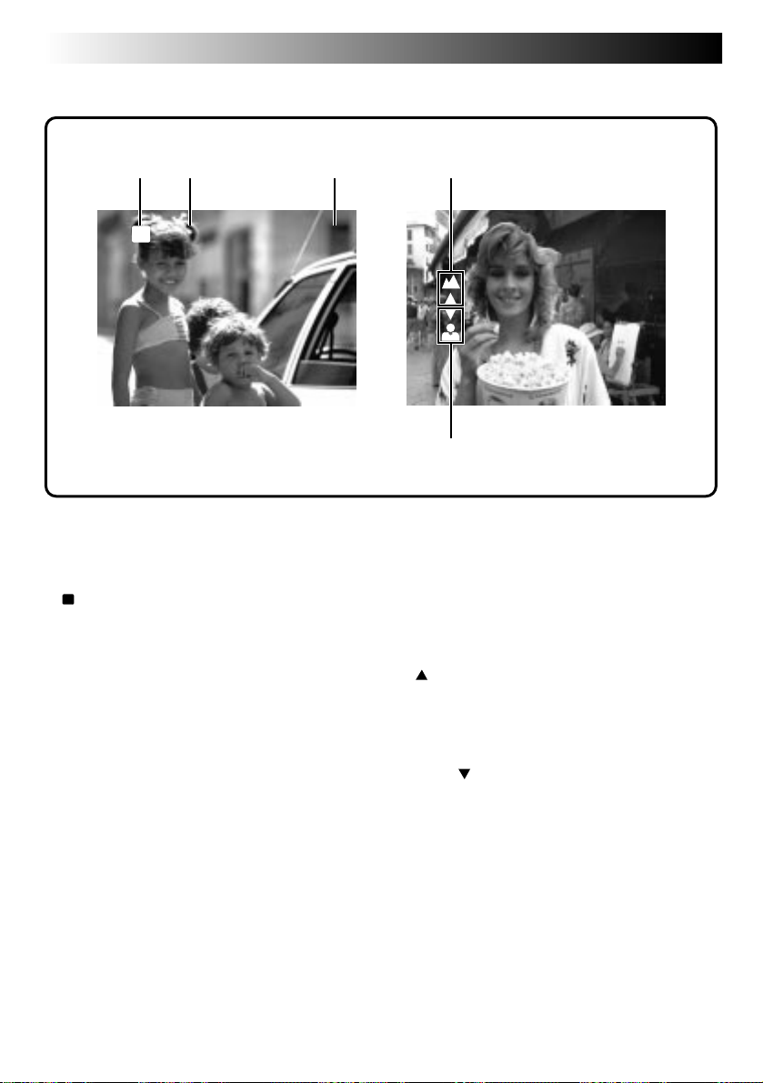
58 EN
CONTROLS, CONNECTORS AND INDICATORS
On-Screen Display During Shooting (cont.)
(Cont.)
12 3
CF
FINE 001
Information Displayed Between Shutter
Release and Storage of Image in Memory
CF
1
Icon ..................................... Z pg. 46
Appears when the image is stored in a
Compact Flash card.
2 Picture Quality Mode (FINE/STD/
ECONOMY) .............................
3 Image Number
Displays the index number given to the
image file.
Z pg. 15
4
5
Icons Displayed During Manual Focusing
These icons are displayed when manual focusing is
selected.
4Far .......................................... Z pg. 26
Rotate the FOCUS Dial (MENU Jog Dial)
upward to focus on a farther subject. When
rotating the FOCUS Dial (MENU Jog Dial),
is displayed.
5 Near ........................................ Z pg. 26
Rotate the FOCUS Dial (MENU Jog Dial)
downward to focus on a nearer subject.
When rotating the FOCUS Dial (MENU Jog
Dial),
is displayed.
Page 59

On-Screen Display During Playback
When the Power Dial is set to “
playback screen.
Each press of the DISPLAY Button switches the screen as shown below.
”, press the DISPLAY Button to view the information display over the
PLAY
EN 59
Playback image
12 34
CF
7
CF
1
Icon ..................................... Z pg. 46
Appears when an image stored in a
Compact Flash card is played back.
2 Picture Quality Mode ................ Z pg. 15
Displays the Picture Quality mode used for
the image.
3 Image Number
Displays the index number given to the
image file.
4 Total Number of Images
Displays the total number of stored images.
Playback image and
information display
021/FINE 030
12. 1998
27.
4:05:23
1
5Date ........................................ Z pg. 10
6 Time ........................................ Z pg. 10
7 Battery Power Remaining
Displays the approximate battery power
remaining.
5
6
Page 60
60 EN
As this digital still camera is controlled by a microcomputer, it may occasionally malfunction due to noise or
interference. In such a case, remove the power supply (batteries or AC power adapter), push the Reset
Switch (Z pg. 56) and retry using the camera. If the trouble still persists and it cannot be solved by referring
to the following table, please consult your nearest JVC dealer.
TROUBLESHOOTING
SYMPTOM CORRECTIVE ACTION PAGE
Power
No power is supplied.
● Is the battery dead?
● Are the batteries loaded in the correct direction?
● Is the power supply connected properly?
Shooting
The LCD monitor flickers in the
Standard View mode (colour
display).
Shooting is impossible.
Images do not appear.
The menu screens are not available.
Although the Shutter Release Button
is half-pressed, focusing is not
possible.
Images become dark when sunlight
is captured by the camera.
The LCD monitor is dark or whitish.
The message “MEMORY FULL”
appears.
Images take on a strobe-like effect.
There is colour noise in the image.
During flash shooting, power turns
off.
● The battery power is low. Replace the batteries.
● Is the Power Dial set to “
● Switch off the camera, then on again.
● Is the Power Dial set to “A”?
● Is focusing set to manual adjustment?
● Are you shooting under low light or are you
shooting a subject which has no contrast?
● This is not a malfunction.
● Turn the lens to adjust the LCD monitor angle or
adjust the brightness.
● Is the image being played back in a cold place?
In cold areas, the LCD monitor appears slightly
dark. This is not a malfunction.
● The LCD monitor's lamp is reaching the end of
its service life. Consult your nearest JVC dealer.
● When the built-in memory is full and no more
shooting is possible, this message appears. Use a
blank Compact Flash card or transfer the stored
images to a Windows® PC or Macintosh® and
save them. Then, delete the images from the
camera's built-in memory to make room for new
shots.
● This is not a malfunction.
● This is not a malfunction.
● During flash shooting, if the remaining battery
power is half-full or less, the power may turn off.
PLAY
”?
47–53
8
9
8
14
14
14
26
—
12
36
—
—
20
Page 61

SYMPTOM CORRECTIVE ACTION PAGE
Others
The image on the LCD monitor
appears distorted.
The date/time is not displayed
properly.
A Compact Flash card cannot be
inserted.
None of the buttons or controls
function on the camera.
Small coloured or black spots
appear on the LCD monitor.
Preset frame images do not appear.
● Is the surface or the edge of the LCD monitor
being pressed? If so, release your hand and
leave it for a while.
● The remaining power of the built-in clock
battery is close to nil. Connect the camera to the
AC power adapter and plug it in for over 24
hours.
● Is the Compact Flash card being held in the
correct direction?
● Switch the camera off, remove the power supply
(battery or AC power adapter) and press the
Reset Switch on the bottom of the camera with a
pin or similar object. All settings are returned to
their factory presets.
● The LCD monitor is manufactured using highprecision technology, however, a few pixels on
it may be always off (black) or on (lit). This is
not due to any defect of the camera. (Functioning dots: more than 99.99%)
● If the built-in memory is initialized after the
message “PLEASE FORMAT” appears, the preset
frames are erased. Consult your nearest JVC
dealer.
EN 61
—
9
44
9
56
—
45
Page 62

62 EN
Display Description
NO IMAGES STORED
CONTAINS PROTECTED IMAGES
TRANSMISSION IN PROGRESS
RECEPTION IN PROGRESS
TOO MANY COPIES
IMAGE COPYING IN PROGRESS
FORMATTING IN PROGRESS
TRANSMISSION TO BE STOPPED
RECEPTION TO BE STOPPED
TRANSMISSION FAILED
RECEPTION FAILED
PC MODE
DELETING IN PROGRESS
PLEASE INITIALIZE
DISPLAY AND MESSAGES
● Appears during playback when no images are stored in the
built-in memory or Compact Flash card.
● Appears when there are protected images in the camera when
all-image deletion is attempted. In this case, all images can be
deleted by unprotecting the protected images.
● Appears while the camera is transmitting image data via the IR
communication system.
● Appears while the camera is receiving image data via the IR
communication system.
● Appears when copying is impossible because there is not
enough space at the destination. Either make space at the
destination or reduce the number of images to be copied.
● Appears while image data is being copied.
● Appears while a Compact Flash card or the built-in memory is
being initialized.
● Appears when image transmission is cancelled.
● Appears when image reception is cancelled.
● Appears when data was not sent due to failure.
● Appears when data was not received due to failure.
● Appears during image transmission through a PC connection.
● Appears while the camera is deleting images.
● Appears when a malfunction occurs in the built-in memory.
When this appears, initialize the built-in memory.
Page 63

CAUTIONS
EN 63
AC Power Adapter (Optional)
1. To prevent fire, electric shock or injury...
.... DO NOT use the AC power adapter with any
power source or voltage not supported.
.... DO NOT modify or disassemble the AC
power adapter. Never attempt to repair or
check it yourself, as this is very dangerous.
Consult your nearest JVC dealer for maintenance on the AC power adapter.
.... DO NOT connect any power cord other than
the one provided to the AC power adapter. If
the power cord's performance or design is
different, fire or electric shock may result.
.... first connect the power cord to the AC power
adapter. If the power cord is connected first
to an AC outlet, and the AC power adapter's
connector comes in contact with a metallic
object, a short-circuit will occur which may
result in fire or injury.
2. To prevent fire, malfunction or electric
shock...
.... DO NOT use any AC power adapter except
the one specified with this digital still
camera. If the AC adapter's performance or
design is different than what the digital
camera is designed for, fire, malfunction or
electric shocks may result. Before using,
thoroughly read the instructions of the digital
still camera and the AC power adapter.
3. To avoid malfunction...
.... connect the power cord to the AC power
adapter securely. If the power cord is
disconnected during use of the camera,
shooting or playback may become impossible and the image data may become corrupt.
Batteries
•This camera requires 4 LR6 (AA)-size alkaline
batteries. LR6 (AA)-size nickel-cadmium (Ni-Cd)
or nickel-metal hydrode (Ni-MH) batteries can
also be used. Note that the battery power
remaining indicated by the camera does not take
the type of batteries being used into account.
•Do not use manganese batteries as they do not
have sufficient energy to power this camera.
•Use the batteries properly. The wrong use can
cause them to leak, or become hot or damaged.
When replacing the batteries, insert them with
their (+) and (–) polarity marks properly aligned, as
indicated by the orientation marking inside the
battery cover.
•When the batteries become cold in cooler
temperatures (below 10 °C), such as outdoors in
winter, their lifetime shortens and they may cease
to function. If this happens, place the batteries in
your pocket or other warm, protected place for a
short time, then re-insert them in the camera. We
recommend using LR6 (AA)-size nickel-cadmium
batteries as they can power the camera even at
0°C.
•If the (+) and (–) polarity marks are dirty with
sweat or oil, this will cause contact failure. Wipe
them off with a dry cloth, then use the batteries.
•Keep new batteries handy if you plan to use the
camera for an extended period of time (for travel,
etc.).
•Before using Ni-Cd or Ni-MH batteries, be sure to
charge them fully using their designated battery
charger.
•Since batteries become hot after they are exhausted, be careful when replacing them with
new ones.
•If the batteries are not used for an extended
period, remove them from the camera to avoid
battery leakage, which can cause malfunctions to
occur.
•Do not use different kinds of batteries or old and
new batteries together.
•Do not expose the batteries to excessive heat, as it
may cause them to leak or explode.
•Do not dispose of batteries in fire.
•Do not shortcircuit the terminals. Keep them away
from metallic objects when not in use.
Page 64

64 EN
Built-in Rechargeable Battery
To store the date/time in memory, a rechargeable
battery is integrated in the camera. As long as the
camera is connected to an AC outlet using the AC
power adapter, or the batteries installed in the
camera continue to supply power to the camera, the
built-in battery is always charged. However, if the
camera is not used for approx. 3 months, the builtin battery will become discharged and the date/time
stored in memory will be lost. When this occurs,
connect the camera to an AC outlet using the AC
power adapter for over 24 hours to charge the builtin rechargeable battery. Before using the camera
again, set the date/time.
Note that it is possible to use the camera without
setting the date/time.
Main Unit
1. For safety, DO NOT . . .
.... open the camera’s chassis.
.... disassemble or modify the unit.
.... allow inflammables, water or metallic objects
to enter the unit.
.... remove the batteries or disconnect the power
supply while the power is on.
2. Avoid using the unit . . .
.... in places subject to excessive humidity or
dust.
.... in places subject to soot or steam such as
near a cooking stove.
.... in places subject to excessive shock or
vibration.
.... near a television set.
.... near appliances generating strong magnetic
or electric fields (speakers, broadcasting
antennas, etc.).
.... in places subject to extremely high (over
40°C) or extremely low (under 0°C) tempera-
tures.
3. DO NOT leave the unit . . .
.... in places of over 50°C.
.... in places where humidity is extremely low.
(below 35%) or extremely high (above 80%).
.... in direct sunlight.
.... in a closed car in summer.
.... near a heater.
4. To protect the unit, DO NOT . . .
.... allow it to become wet.
.... drop the unit or strike it against hard objects.
.... subject it to shock or excessive vibration
during transportation.
.... keep the lens directed at extremely bright
objects for long periods.
.... carry it by holding the lens. Be sure to hold
the main unit with both hands.
.... swing it excessively when using the hand
strap.
Page 65

EN 65
LCD Monitor
1. To prevent damage to the LCD monitor,
DO NOT . . .
.... push it strongly or apply any shocks.
.... place the camcorder with the LCD monitor
on the bottom.
2. To prolong service life . . .
.... avoid rubbing it with coarse cloth.
3. Be aware of the following phenomena for
LCD monitor use. These are not malfunctions . . .
•While using the camera, the surface around the
LCD monitor and/or the back of the LCD monitor
may heat up.
•If you leave power on for a long time, the surface
around the LCD monitor becomes hot.
How To Handle A CD-ROM
•Take care not to soil or scratch the mirror surface
(opposite to the printed surface). Do not write
anything or put a sticker on either the front or
back surface. If the CD-ROM gets dirty, gently
wipe it with a soft cloth outward from the centre
hole using a circular motion.
•Do not use conventional disc cleaners or cleaning
spray.
•Do not bend the CD-ROM or touch its mirror
surface.
•Do not store your CD-ROM in a dusty, hot or
humid environment. Keep it away from direct
sunlight.
About moisture condensation . . .
● You may have observed that pouring a cold
liquid into a glass will cause drops of water to
form on the glass’ outer surface. This same
phenomenon occurs on the lens of the
camera when it is moved from a cool place to
a warm place, after heating a cold room,
under extremely humid conditions or in a
place directly subjected to the cool air from
an air conditioner.
Serious malfunctioning
If malfunctioning occurs, stop using the unit
immediately and consult your local JVC dealer.
Page 66

66 EN
Dimensions : 129 (W) x 74 (H) x 39 (D) mm
Power consumption : 4.2 W
Weight : Approx. 260 g
Power : DC 6 V
Flash : Built-in,
Effective shooting distance: 0.5 to 2 m
(with zoom set all the way to “W”)
LCD monitor : 1.8”
Tripod mounting socket : Provided on the bottom panel
Storage media : Built-in flash memory (storage capacity: approx. 3 MB),
Compact Flash card (commercially available)
Compression system : JPEG (compatible)
CCD : 1/4”, 350,000 pixel, progressive scan, complementary colour
CCD
Focal distance : 4.5 to 45 mm
(equivalent to 43 mm to 430 mm on a 35 mm camera)
Zoom : 10X optical zoom
Filter diameter : 27 mm
Aperture (F-number) : F1.6
Minimum subject distance : Approx. 7 cm (with the zoom set all the way to “W”)
Approx. 1 m (with the zoom set all the way to “T”)
Photometry method : TTL CCD photometry
Shutter system : Electronic shutter
Shutter speeds : Auto/Manual (1/7 to 1/1000 sec.)
White balance : Auto/Manual (Fine/Cloudy/Halogen/M.W.B.)
Focusing : Auto/Manual (7 cm to
Picture quality : 3 modes (Fine/Standard/Economy)
Number of storable images : Fine : approx. 30
Standard : approx. 50
Economy : approx. 100
PC jack : 2.5 mm dia., 3-pole plug
Video output jack : 3.5 mm dia., 2-pole plug (PAL)
DC input jack :6 V
Infrared transmitter/receiver : IrDA Ver. 1.0 (IrTran-P compatible)
MAJOR SPECIFICATIONS
)
E. & O. E. Design and specifications subject to change without notice.
Page 67

INDEX
A
AC outlet.................................. pg. 9
AC power adapter .................... pg. 9
Auto playback .......................... pg. 31
B
Battery power remaining .......... pg. 8, 57, 59
Black-and-white effect ............. pg. 38
C
Camera setup check ................. pg. 17
Compact Flash card ................. pg. 44
Copy ........................................ pg. 47 – 49
D
Date/time ................................. pg. 10
Deleting images ....................... pg. 36, 37
Digital Printer........................... pg. 52
E
Effects ...................................... pg. 38, 39
Exposure compensation ........... pg. 21
F
Flash ........................................ pg. 20, 29
Frames ..................................... pg. 40, 41
Focusing .................................. pg. 26
Formatting................................ pg. 45
Full Auto shooting .................... pg. 16
I
Index playback......................... pg. 33
INDEX screen........................... pg. 32
Infrared image
communication ...................... pg. 50, 51
Infrared transmitter/receiver ..... pg. 51
IrDA transfer ............................ pg. 50
IrTran-P .................................... pg. 50
EN 67
M
Manual focusing ...................... pg. 26
Manual white balance
(M.W.B.) ................................ pg. 22, 23
Multi-image screen .................. pg. 42, 43
N
Normal playback ..................... pg. 31
P
Picture Quality mode ............... pg. 15
Playback mode ........................ pg. 31
Power Save mode .................... pg. 28
Power supply ........................... pg. 8, 9
Protecting images ..................... pg. 34, 35
S
Self-Timer................................. pg. 19
Sepia effect .............................. pg. 38
Shooting modes ....................... pg. 14
Shutter speeds .......................... pg. 24, 25
T
TV monitor............................... pg. 30
V
View modes ............................. pg. 27
W
White balance.......................... pg. 22, 23
Z
Zoom-in effect ......................... pg. 18, 39
16-split screen.......................... pg. 42, 43
4-split screen............................ pg. 42, 43
Page 68

GC-S1
COPYRIGHT© 1998 VICTOR COMPANY OF JAPAN, LTD.
EG/EK
Printed in Japan
0398MNV*UN*VP
VICTOR COMPANY OF JAPAN, LIMITED
EN
 Loading...