

Page 1
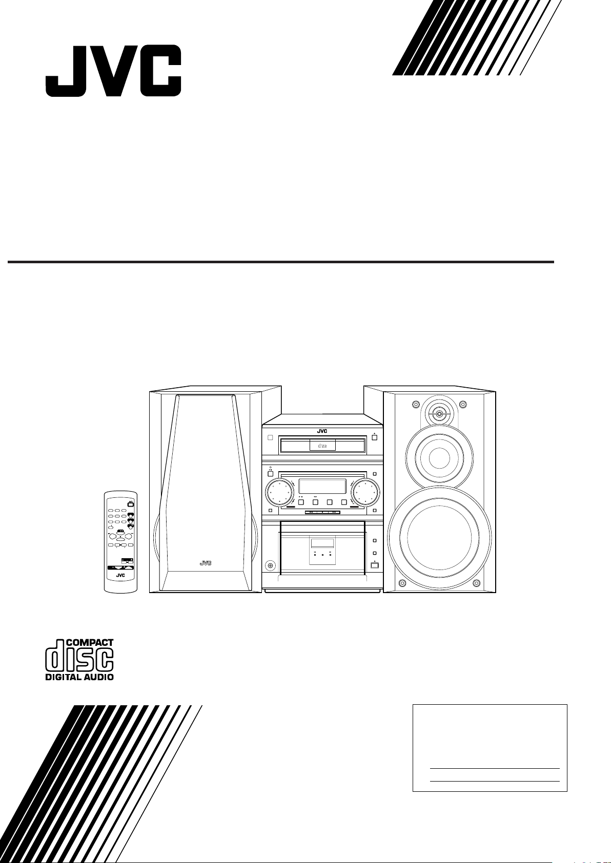
COMPACT COMPONENT SYSTEM
SYSTEME DE COMPOSANTS COMPACT
FS-P7 — Consists of CA-FSP7 and SP-UXP7.
COMPACT
DIGITAL AUDIO
CD-R/RW PLAYBACK
STANDBY / ON
COMPACT COMPONENT SYSTEM FS·P7
STANDBY / ON
CLOCK
SLEEP
DISPLAYDIMMER
REPEATRANDOMPROG
AUTO
SOUND
FM MODE
PRESET
MODE
CD
CD
CANCEL MULTI KEY SET
VOLUME
RM-SFSP7J REMOTE CONTROL
CD TAPE FM/AM
STANDBY/ON
MD/AUX
FM/AM
TAPE
AHB PRO
LEVEL
SOUND
PHONES
/
INSTRUCTIONS
MANUEL D’INSTRUCTIONS
REC
AUTO REVERSE
MD/AUX
VOLUMEAHB PRO
TIMER
REV.MODE
REC
For Customer Use:
Enter below the Model No. and Serial No.
which are located either on the rear, bottom or side of the cabinet. Retain this
information for future reference.
Model No.
Serial No.
GVT0055-001A
[J]
Page 2
Warnings, Cautions and Others
Mises en garde, précautions et indications diverses
CAUTION
RISK OF ELECTRIC SHOCK
DO NOT OPEN
CAUTION: TO REDUCE THE RISK OF ELECTRIC SHOCK,
DO NOT REMOVE COVER (OR BACK).
NO USER SERVICEABLE PARTS INSIDE.
REFER SERVICING TO QUALIFIED SERVICE PERSONNEL.
The lightning flash with arrowhead symbol,
within an equilateral triangle is intended to
alert the user to the presence of uninsulated
"dangerous voltage" within the product's
enclosure that may be of sufficient
magnitude to constitute a risk of electric
shock to persons.
The exclamation point within an equilateral
triangle is intended to alert the user to the
presence of important operating and
maintenance (servicing) instructions in the
literature accompanying the appliance.
For U.S.A.
This equipment has been tested and found to comply with the limits
for a Class B digital device, pursuant to part 15 of the FCC Rules.
These limits are designed to provide reasonable protection against
harmful interference in a residential installation.
This equipment generates, uses and can radiate radio frequency
energy and, if not installed and used in accordance with the
instructions, may cause harmful interference to radio
communications. However, there is no guarantee that interference
will not occur in a particular installation. If this equipment does cause
harmful interference to radio or television reception, which can be
determined by turning the equipment off and on, the user is
encouraged to try to correct the interference by one or more of the
following measures:
Reorient or relocate the receiving antenna.
Increase the separation between the equipment and receiver.
Connect the equipment into an outlet on a circuit different from that
to which the receiver is connected.
Consult the dealer or an experienced radio/TV technician for help.
WARNING: TO REDUCE THE RISK OF FIRE
OR ELECTRIC SHOCK, DO NOT EXPOSE
THIS APPLIANCE TO RAIN OR MOISTURE.
CAUTION
To reduce the risk of electrical shocks, fire, etc.:
1. Do not remove screws, covers or cabinet.
2. Do not expose this appliance to rain or moisture.
ATTENTION
Afin d’éviter tout risque d’électrocution, d’incendie, etc.:
1. Ne pas enlever les vis ni les panneaux et ne pas ouvrir
le coffret de l’appareil.
2. Ne pas exposer l’appareil à la pluie ni à l’humidité.
Caution –– STANDBY/ON button!
Disconnect the mains plug to shut the power off
completely (the STANDBY/ON lamp goes off).
The STANDBY/ON button in any position does not
disconnect the mains line.
• When the unit is on standby, the STANDBY/ON lamp
lights red.
• When the unit is turned on, the STANDBY/ON lamp lights
green.
The power can be remote controlled.
Attention –– Commutateur STANDBY/ON!
Déconnectez la prise d’alimentation secteur pour mettre
l’appareil complètement hors tension (le témoin STANDBY/
ON s’éteint).
L’interrupteur STANDBY/ON, sur n’importe quelle
position, ne peut pas déconnecter l’appareil du secteur.
• Quand l’appareil est en mode de veille, le témoin
STANDBY/ON est allumé en rouge.
• Quand l’appareil est sous tension, le témoin
STANDBY/ON est allumé en vert.
L’alimentation peut être télécommandée.
For Canada/pour le Canada
CAUTION: TO PREVENT ELECTRIC SHOCK, MATCH WIDE
BLADE OF PLUG TO WIDE SLOT, FULLY INSERT.
ATTENTION: POUR EVITER LES CHOCS ELECTRIQUES,
INTRODUIRE LA LAME LA PLUS LARGE DE LA FICHE DANS
LA BORNE CORRESPONDANTE DE LA PRISE ET POUSSER
JUSQUAU FOND.
For Canada/pour le Canada
THIS DIGITAL APPARATUS DOES NOT EXCEED THE CLASS
B LIMITS FOR RADIO NOISE EMISSIONS FROM DIGITAL
APPARATUS AS SET OUT IN THE INTERFERENCE-CAUSING
EQUIPMENT STANDARD ENTITLED “DIGITAL APPARATUS,”
ICES-003 OF THE DEP AR TMENT OF COMMUNICATIONS.
CET APPAREIL NUMERIQUE RESPECTE LES LIMITES DE
BRUITS RADIOELECTRIQUES APPLICABLES AUX APPAREILS
NUMERIQUES DE CLASSE B PRESCRITES DANS LA NORME
SUR LE MATERIEL BROUILLEUR: “APP AREILS NUMERIQUES”,
NMB-003 EDICTEE PAR LE MINISTRE DES
COMMUNICATIONS.
Note to CATV system installer:
This reminder is provided to call the CATV system
installer’s attention to Section 820-40 of the NEC which
provides guidelines for proper grounding and, in particular,
specifies that the cable ground shall be connected to the
grounding system of the building, as close to the point of
cable entry as practical.
1. CLASS 1 LASER PRODUCT
2. CAUTION: Invisible laser radiation when open and interlock
failed or defeated. Avoid direct exposure to beam.
3. CAUTION: Do not open the top cover. There are no user
serviceable parts inside the Unit; leave all servicing to
qualified service personnel.
1. PRODUIT LASER CLASSE 1
2. ATTENTION: Radiation laser invisible quand l'appareil est
ouvert ou que le verrouillage est en panne ou désactivé.
Eviter une exposition directe au rayon.
3. ATTENTION: Ne pas ouvrir le couvercle du dessus. Il n'y a
aucune pièce utilisable à l'intérieur. Laisser à un personnel
qualifié le soin de réparer votre appareil.
– G-1 –
Page 3
Instructions for safe use
(Statement in accordance with the UL standards)
1) Read Instructions — Read carefully this instructions for
your safe use before this appliance is installed, wireconnected, and operated.
2) Retain Instructions — For your future reference, retain
this instruction.
3) Follow Instructions — Follow and obey all warnings,
cautions and instructions marked on this appliance and
this instruction.
4) Water and Moisture — Do not expose this appliance to
rain, water and moisture, or operate it near water — for
example near a bathtub, wash bowl, kitchen sink,
laundry tub, in a wet basement or near a swimming pool,
and the like.
5) Ventilation and Heat — This appliance should be
situated so that its location does not interfere with its
proper ventilation. For example, this appliance should
not be situated on a bed, sofa, rug, or similar surface
that may block the ventilation openings; or, placed in a
built-in installation, such as a bookcase or cabinet that
may impede the flow of air through the ventilation
openings. This appliance should be situated away from
heat sources such as radiators, heat registers, stoves,
or other appliances (including amplifiers) that produce
heat.
6) Power sources — This appliance should be connected
to a power supply only of the type as marked on this
appliance.
7) Polarization — The precautions that should be taken so
that the polarization means of this appliance is not
defeated.
8) Power Cord Protection — Power supply cords should be
routed so that they are not likely to be walked on or
pinched by items placed upon or against them, paying
particular attention to cords at plugs, convenience
receptacles, and the point where they exit from the
appliance.
9) Cleaning — The appliance should be cleaned only as
recommended by the manufacturer.
10)Power Lines — An outdoor antenna should be located
away from power lines.
11)Outdoor Antenna Grounding — If this appliance is
provided with means to connect the outdoor antenna
and outside antenna is connected to this appliance, be
sure the antenna system is grounded so as to provide
some protection against voltage surges and built-up
static charges. Article 810 of the National Electrical
Code, ANSI/ NFPA 70, provides information with regard
to proper grounding of the mast and supporting
structure, grounding of the lead-in wire to an antennadischarge unit, size of grounding conductors, location of
antenna-discharge unit, connection to grounding
electrodes, and requirements for the grounding
electrode. Example of antenna grounding is illustrated in
here.
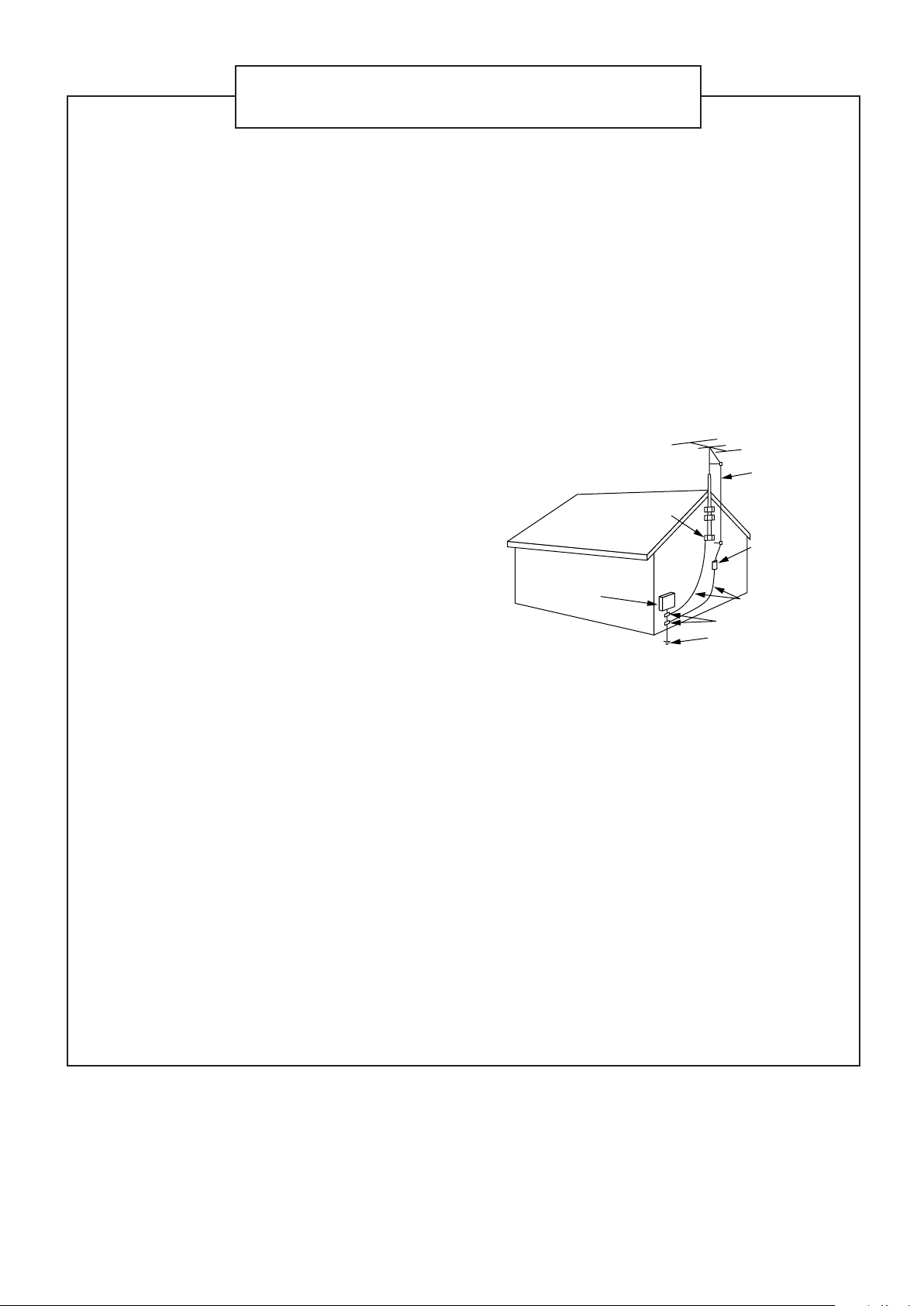
EXAMPLE OF ANTENNA GROUNDING AS PER
NATIONAL ELECTRICAL CODE
ANTENNA
LEAD IN
WIRE
GROUND
CLAMP
ANTENNA
DISCHARGE UNIT
(NEC SECTION 810–20)
ELECTRIC
SERVICE
EQUIPMENT
NEC
— NATIONAL ELECTRICAL CODE
GROUNDING CONDUCTORS
(NEC SECTION 810–21)
GROUND CLAMPS
POWER SERVICE GROUNDING
ELECTRODE SYSTEM
(NEC ART 250. PART H)
12)Nonuse Periods — The power cord of the appliance
should be unplugged from the outlet when left unused
for a long period of time.
13)Object and Liquid Entry — Care should be taken so that
objects do not fall and liquids are not spilled into the
enclosure through openings.
14)Damage Requiring Service — The appliance should be
serviced by qualified service personnel when : (a) The
power-supply cord or the plug has been damaged; or (b)
Objects have fallen, or liquid has been spilled into the
appliance; or (c) The appliance has been exposed to
rain; or (d) The appliance does not appear to operate
normally or exhibits a marked change in performance; or
(e) The appliance has been dropped, or the enclosure
damaged.
15)Servicing — The user should not attempt to service the
appliance beyond that described in the operating
instructions. All other servicing should be referred to
qualified service personnel.
– G-2 –
Page 4
Introduction
We would like to thank you for purchasing one of our JVC products.
Before operating this unit, read this manual carefully and thoroughly to
obtain the best possible performance from your unit, and retain this manual
for future reference.
About This Manual
This manual is organized as follows:
• The manual mainly explains operations using the
buttons on the remote control.
You can use the buttons both on the remote control and
on the unit for the same operations if they have the
same or similar names (or marks), unless mentioned
otherwise.
• Basic and common information that is the same for many
functions is grouped in one place, and is not repeated in
each procedure. For instance, we do not repeat the
information about turning on/off the unit, setting the
volume, changing the sound effects, and others, which are
explained in the section “Common Operations” on pages 9
and 10.
• The following marks are used in this manual:
Gives you warnings and cautions to prevent
from damage or risk of fire/electric shock.
Also gives you information which is not good
for obtaining the best possible performance
from the unit.
Gives you information and hints you had better
know.
Power sources
• When unplugging from the wall outlet, always pull the
plug, not the AC power cord.
DO NOT handle the AC power cord with wet
hands.
Moisture condensation
Moisture may condense on the lens inside the unit in the
following cases:
• After starting heating in the room
• In a damp room
• If the unit is brought directly from a cold to a warm place
Should this occur, the unit may malfunction. In this case,
leave the unit turned on for a few hours until the moisture
evaporates, unplug the AC power cord, and then plug it in
again.
Others
• Should any metallic object or liquid fall into the unit,
unplug the unit and consult your dealer before operating
any further.
• If you are not going to operate the unit for an extended
period of time, unplug the AC power cord from the wall
outlet.
Precautions
Installation
• Install in a place which is level, dry and neither too hot nor
too cold — between 5˚C (41˚F) and 35˚C (95˚F).
• Install the unit in a location with adequate ventilation to
prevent internal heat built-up in the unit.
• Leave sufficient distance between the unit and the TV.
• Keep the speakers away from the TV to avoid interference
with TV.
DO NOT install the unit in a location near heat
sources, or in a place subject to direct sunlight,
excessive dust or vibration.
DO NOT disassemble the unit since there are no
user serviceable parts inside.
If anything goes wrong, unplug the AC power cord and
consult your dealer.
– 1 –
Page 5

Contents
Location of the Buttons and Controls....................... 3
Front Panel ................................................................. 3
Remote Control .......................................................... 5
Getting Started............................................................ 6
Supplied Accessories.................................................. 6
Putting the Batteries into the Remote Control ........... 6
Connecting Antennas ................................................. 6
Connecting Speakers .................................................. 7
Connecting Other Equipment..................................... 8
Common Operations .................................................. 9
Turning On the Po wer ................................................. 9
Setting the Clock ........................................................ 9
Selecting the Sources and Starting Play ....................... 9
Adjusting the Volume............................................... 10
Selecting the Display Brightness ............................. 10
Reinforcing the Bass Sound ..................................... 10
Selecting the Sound Modes ...................................... 10
Listening to FM and AM Broadcasts...................... 11
Tuning in a Station ................................................... 11
Presetting Stations .................................................... 11
Tuning in a Preset Station ........................................ 11
Playing Back CDs (CD/CD-R/CD-RW).................. 12
Playing Back the Entire CD — Normal Play........... 12
Basic CD Operations................................................ 12
Programming the Playing Order of the Tracks
— Program Play ................................................. 13
Playing at Random — Random Play ....................... 14
Repeating Tracks — Repeat Play............................. 14
Prohibiting Disc Ejection — Tray Lock................... 14
Playing Back Tapes................................................... 15
Playing Back a Tape ................................................. 15
Recording .................................................................. 16
Recording on a Tape ................................................. 16
CD Direct Recording................................................. 17
One Track Recording ................................................ 17
Using the Timers....................................................... 18
Using Daily Timer and Recording Timer ................. 18
Using Sleep Timer.................................................... 19
Troubleshooting ........................................................ 20
Maintenance .............................................................. 21
Specifications............................................................. 22
– 2 –
Page 6
Location of the Buttons and Controls
Become familiar with the buttons and controls on your unit.
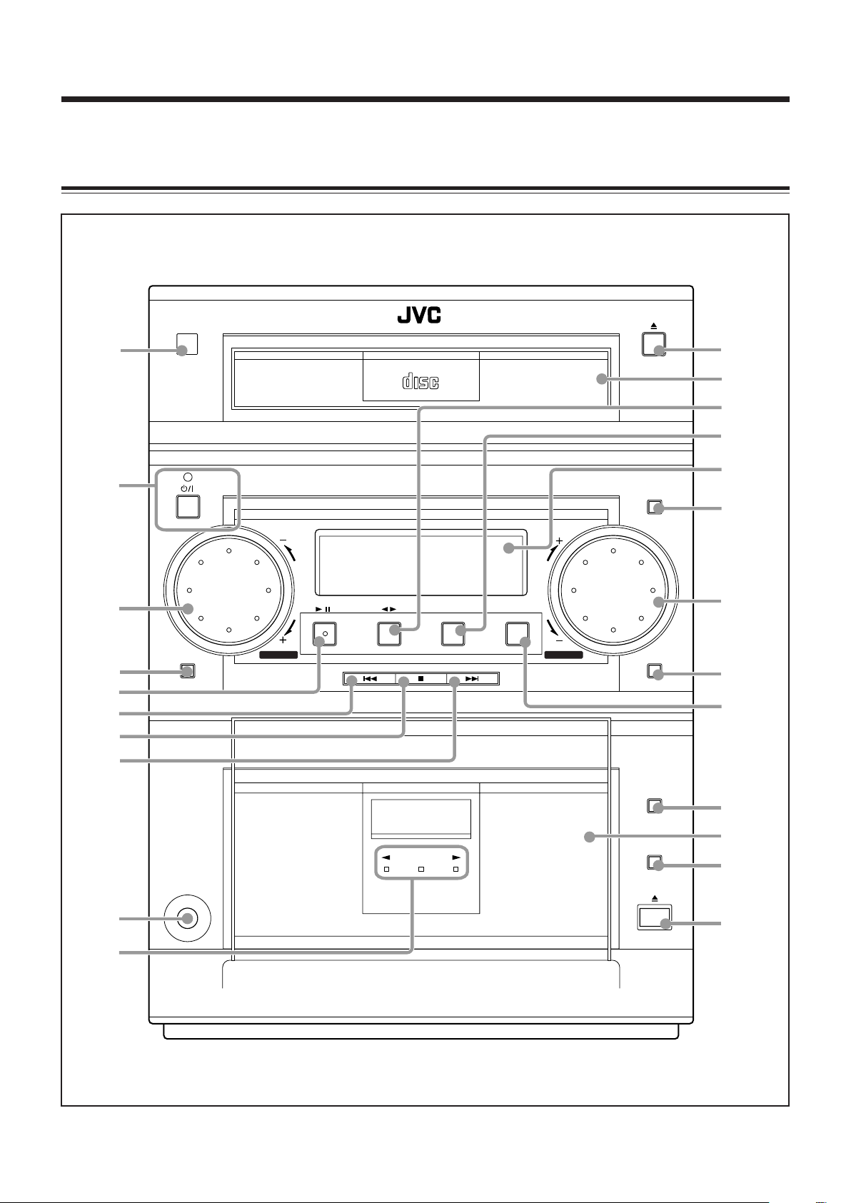
Front Panel
Front Panel
1
2
3
4
5
6
7
8
STANDBY / ON
STANDBY / ON
SOUND
COMPACT
DIGITAL AUDIO
COMPACT COMPONENT SYSTEM FS·P7
CD TAPE FM/AM
/
CD-R/RW PLAYBACK
MD/AUX
VOLUMEAHB PRO
q
w
e
r
t
CLOCK
y
u
TIMER
i
o
9
p
PHONES
REC
AUTO REVERSE
– 3 –
REV.MODE
REC
;
a
s
d
Page 7
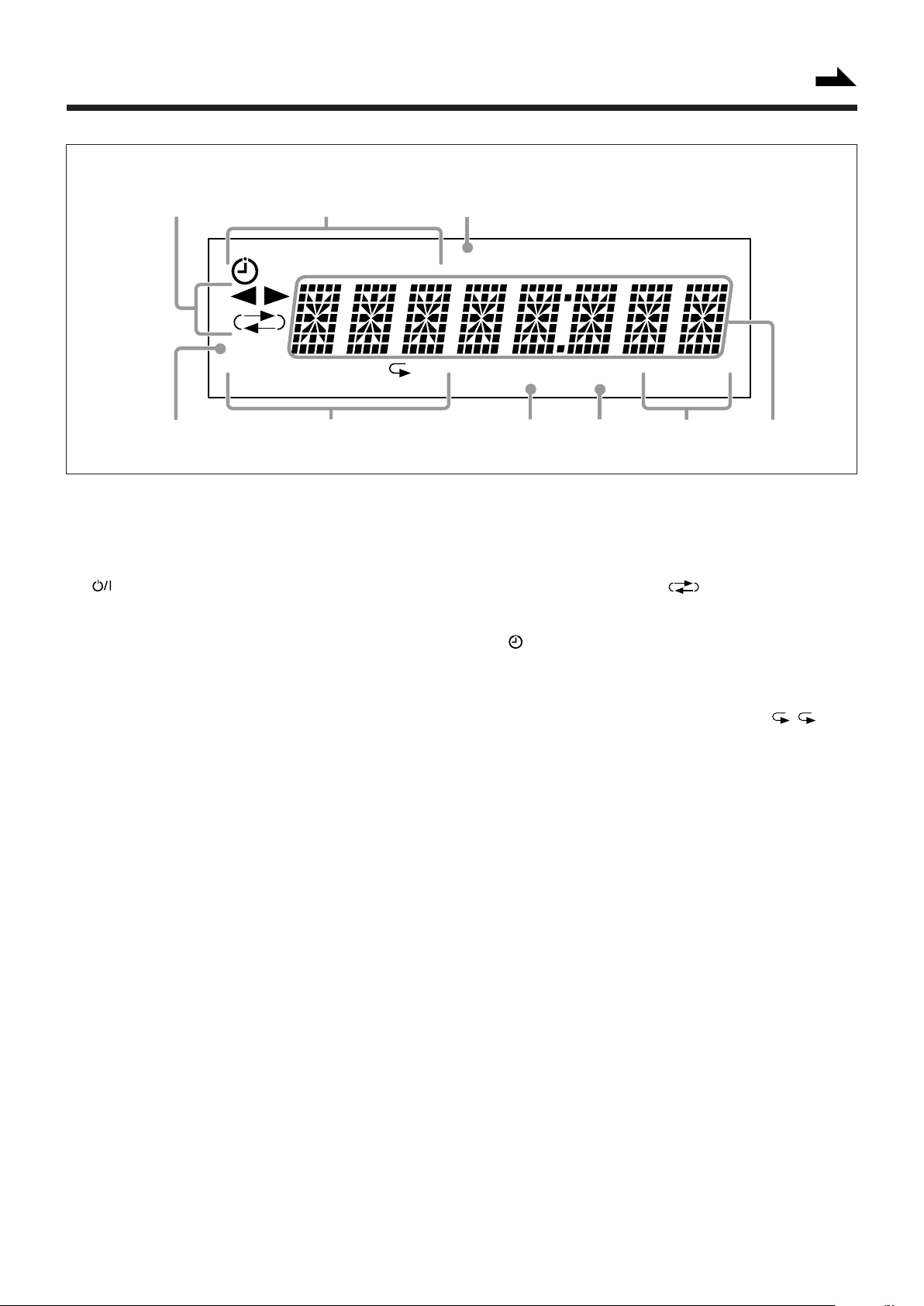
Display Window
Continued
1
[
DAIL Y REC SLEEP
2
CLOCK
PRGM
4
See pages in the parentheses for details.
RANDOM
5
Front Panel
1 Remote sensor
2 (STANDBY/ON) button and STANDBY/ON lamp
(9, 14, 19)
3 AHB (Active Hyper Bass) PRO + / – control (10)
4 SOUND button (10)
5 CD 3/8 (play/pause) button (9, 12, 17)
Pressing this button also turns on the unit.
6 4 (reverse search) button (9, 11, 12, 15, 18)
7 7 (stop) button (12 – 17)
8 ¢ (forward search) button (9, 11, 12, 14, 15, 18)
9 PHONES jack (10)
p Tape operation lamps (15, 16)
• 2 3 (tape direction) and REC lamps
q 0 (disc tray open/close) button (12)
Pressing this button also turns on the unit.
w Disc tray
e TAPE 2 3 button (9, 15, 16)
Pressing this button also turns on the unit.
r FM/AM button (9, 11)
Pressing this button also turns on the unit.
t Display window
y CLOCK button (9)
u VOLUME + / – control (10)
i TIMER button (18, 19)
o MD/AUX button (9)
Pressing this button also turns on the unit.
; REV.MODE (reverse mode) button (15 – 17)
a Cassette holder
s REC button (16, 17)
d 0 (eject) button for cassette deck (15 – 17)
ALL BASS SOUND MONOST
3
]
REC
6
Display Window
1 Tape operation indicators
• 2 3 (tape direction) and (reverse mode)
indicators
2 Timer indicators
• (timer), DAILY, REC and SLEEP indicators
3 REC indicator
4 CLOCK indicator
5 CD play mode indicators
• PRGM (program), RANDOM and repeat ( / ALL)
indicators
6 BASS (Active Hyper Bass) indicator
7 SOUND (sound mode) indicator
8 Tuner operation indicators
• MONO and ST (stereo) indicators
9 Main display
• Shows the source name, frequency, etc.
7
89
– 4 –
Page 8
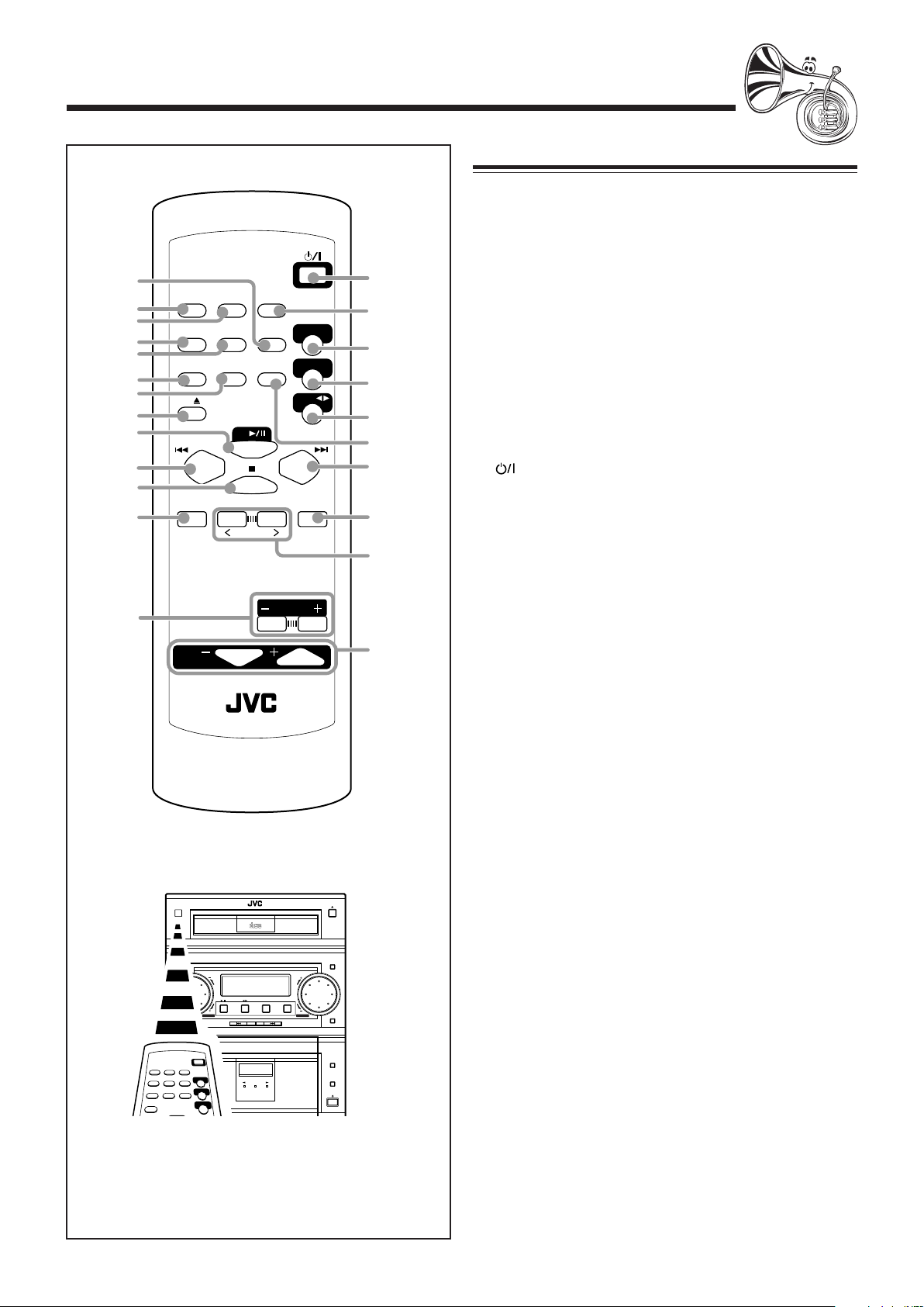
Remote Control
1
2
3
4
5
6
7
8
9
p
q
w
e
DISPLAYDIMMER
AUTO
SOUND
PRESET
MODE
CD
CD
CANCEL
VOLUME
MULTI KEY
RM-SFSP7J REMOTE CONTROL
SLEEP
REPEATRANDOMPROG
FM MODE
AHB PRO
LEVEL
STANDBY/ON
MD/AUX
FM/AM
TAPE
SET
r
t
y
u
i
o
;
a
s
d
Remote Control
1 REPEAT button (14)
2 DIMMER button (10)
3 DISPLAY button (9)
4 PROG (program) button (13)
5 RANDOM button (14)
6 SOUND MODE button (10)
7 AUTO PRESET button (11)
8 CD 0 (disc tray open/close) button (12)
Pressing this button also turns on the unit.
9 CD 3/8 button (9, 12, 13)
Pressing this button also turns on the unit.
p 4 (reverse search) button (11, 12, 15)
q 7 (stop) button (12 – 17)
w CANCEL button (13)
e AHB (Active Hyper Bass) PRO LEVEL + / – buttons (10)
r (STANDBY/ON) button (9)
t SLEEP button (19)
y MD/AUX button (9)
Pressing this button also turns on the unit.
u FM/AM button (9, 11)
Pressing this button also turns on the unit.
i TAPE 2 3 button (9, 15)
Pressing this button also turns on the unit.
o FM MODE button (11)
; ¢ (forward search) button (11, 12, 14, 15)
a SET button (11, 13)
s MULTI KEY > / < buttons (11 – 14)
d VOLUME + / – buttons (10)
COMPACT
DIGITAL AUDIO
CD-R/RW PLAYBACK
STANDBY
COMPACT COMPONENT SYSTEM FS·P7
STANDBY / ON
CD TAPE FM/AM
SOUND
PHONES
REC
AUTO REVERSE
MD/AUX
CLOCK
VOLUMEAHB PRO
TIMER
REV.MODE
REC
When using the remote control, point it at
the remote sensor on the front panel.
– 5 –
Page 9
Getting Started
Supplied Accessories
Continued
English
Connecting Antennas
Make sure that you have all the following items.
The number in the parentheses indicates the quantity of the
pieces supplied.
• AM loop antenna (1)
• FM antenna (1)
• Remote control (1)
• Batteries (2)
• Speaker cords (2 sets)
If anything is missing, consult your dealer immediately.
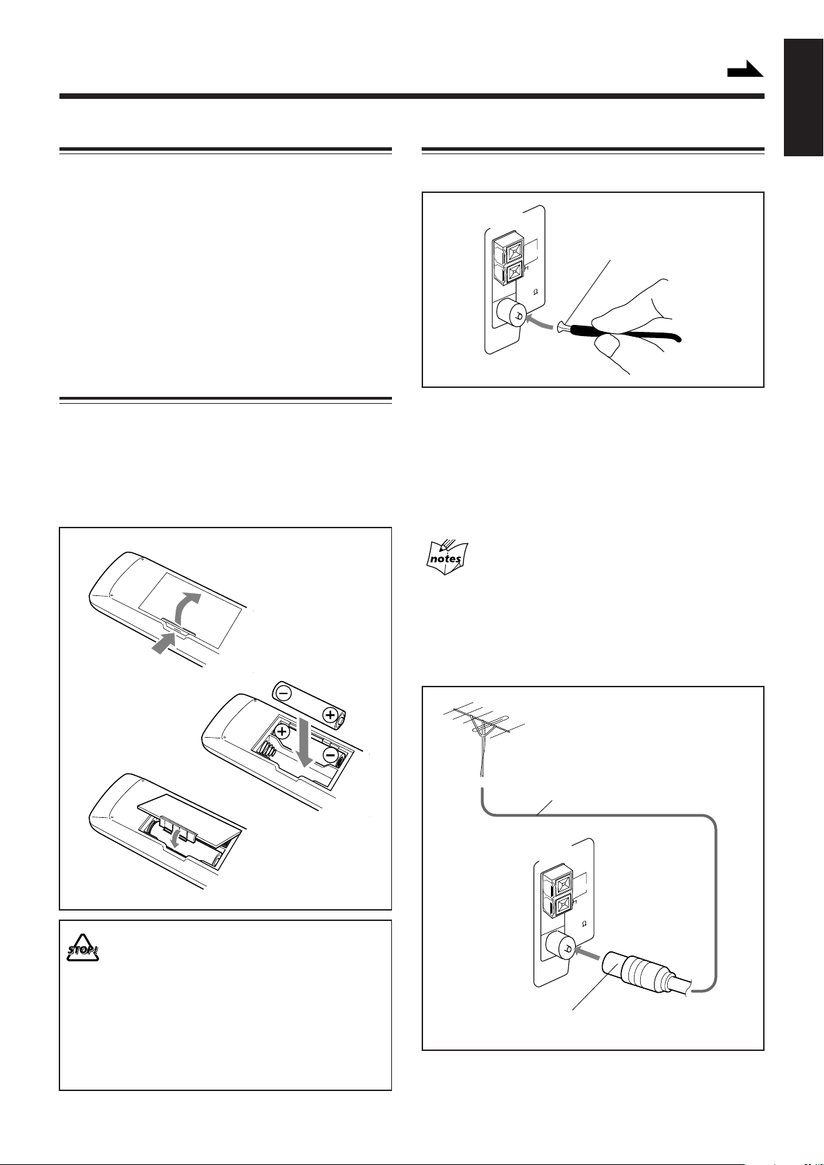
Putting the Batteries into the Remote Control
Insert the batteries — R6(SUM-3)/AA(15F) — into the
remote control, by matching the polarity (+ and –) on the
batteries with the + and – markings on the battery
compartment.
When the remote control can no longer operate the unit,
replace both batteries at the same time.
1
FM antenna
ANTENNA
AM EXT
AM LOOP
FM 75
COAXIAL
FM antenna (supplied)
1 Attach the FM antenna to the FM 75 Ω
COAXIAL terminal.
2 Extend the FM antenna.
3 Fasten it up in the position which gives you
the best reception, then fix it on the wall, etc.
About the supplied FM antenna
The FM antenna supplied with this unit can be used as temporary
measure. If reception is poor, you can connect an outdoor FM
antenna.
R6(SUM-3)/AA(15F)
2
3
• DO NOT use an old battery together with a
new one.
• DO NOT use different types of batteries
together.
• DO NOT expose batteries to heat or flame.
• DO NOT leave the batteries in the battery
compartment when you are not going to use
the remote control for an extended period of
time. Otherwise, it will be damaged from
battery leakage.
To connect an outdoor FM antenna
Before connecting it, disconnect the supplied FM antenna.
Outdoor FM antenna
(not supplied)
Coaxial cable
ANTENNA
AM EXT
AM LOOP
FM 75
COAXIAL
A 75 Ω antenna with coaxial type connector should be
used.
– 6 –
Page 10

AM antenna
Connecting Speakers
1
2
AM loop antenna
(supplied)
]
ANTENNA
AM EXT
AM LOOP
FM
COAXIAL
]
Vinyl-covered wire
(not supplied)
75
SUBWOOFERS
Speaker cords
Red
RIGHT LEFT
SPEAKER
IMPEDANCE
MIN
6
Black
1
MAIN
SPEAKERS
2
RIGHT
SPEAKER
IMPEDANCE
MIN
6
Blue
Speaker cords
3
Gray
LEFT
1 Connect the AM loop antenna to the AM
LOOP terminals as illustrated.
• If the AM loop antenna wire is covered with
vinyl, remove the vinyl by twisting it as
shown in the diagram.
2 Turn the AM loop antenna until you have the
best reception.
To connect an outdoor AM antenna
When reception is poor, connect a single vinyl-covered wire
to the AM EXT terminal and extend it horizontally. (The AM
loop antenna must remain connected.)
For better reception of both FM and AM
• Make sure the antenna conductors do not touch any other
terminals and connecting cords.
• Keep the antennas away from metallic parts of the unit,
connecting cords, and the AC power cord.
Black BlackBlue Blue
Red
Right speaker
Gray
Red
Left speaker
Gray
1 Press and hold the clamp of the speaker
terminal on the rear of the unit.
2 Insert the end of the speaker cord into the
terminal.
Match the polarity of the speaker terminals: Red (+) to
red (+) and black (–) to black (–), gray (+) to gray (+) and
blue (–) to blue (–).
• Remove the vinyl covering the wire by
twisting it as shown in the diagram.
3 Release the finger from the clamp.
IMPORTANT: Use only speakers with the same speaker
impedance as indicated by the speaker terminals on the
rear of the unit.
– 7 –
Page 11

To remove the speaker grilles
The speaker grilles are removed as the illustrations below.
Holes Projections
Speaker grille
To remove the speaker grille, inserting your fingers at the
top of the speaker grille, pull towards you. Then pull the
bottom towards you.
To attach the speaker grille, put the projections of the
speaker grille into the holes of the speaker.
To connect audio equipment with an optical digital
input terminal
You can record CD sound onto the connected digital
equipment.
Protective plug
OPTICAL
DIGITAL
OUT
Before connecting the other equipment,
remove the protective plug from the
terminal.
Audio equipment
with an optical digital
To optical digital input
Connect an optical digital cord (not supplied) between the
optical digital input terminal on the other equipment and the
OPTICAL DIGITAL OUT terminal.
input
Connecting Other Equipment
You can connect both of the analog and digital equipment.
• DO NOT connect any equipment while the power
is on.
• DO NOT plug in any equipment until all
connections are complete.
To connect audio equipment
Be sure that the plugs of the audio cords are colored: White
plugs and jacks are for left audio signals, and red ones for
right audio signals.
AUX
RL
To audio output
To audio input
Audio equipment
By using audio cords (not supplied), connect:
• Between the audio input jacks on the other equipment
and AUX OUT jacks: For recording on the other
equipment.
• Between the audio output jacks on the other equipment
and AUX IN jacks: For playing the other equipment.
OUT
IN
Now, you can plug the AC power cord.
IMPORTANT: Be sure to check all connections to be done
before plugging the AC power cord into a wall outlet.
– 8 –
Page 12

Common Operations
Turning On the Power
When you press the play button — CD 3/8, TAPE 2 3, or
the source selecting button — FM/AM, and MD/AUX, the
unit automatically turns on and starts playback if the source is
ready.
To turn on the unit, press (STANDBY/ON).
The STANDBY/ON lamp on the unit lights green.
STANDBY/ON
STANDBY/ON
STANDBY/ON
To turn off the unit (on standby), press
(STANDBY/ON) again.
The STANDBY/ON lamp lights red.
• The CLOCK indicator flashes on the display until you set
the built-in clock. After setting the clock, the clock time
will appear on the display while the power is off.
• A little power is always consumed even while the unit is on
standby.
To switch off the power supply completely, unplug the AC
power cord from the AC outlet.
When you unplug the AC power cord or if a power
failure occurs
The clock is reset to “AM12:00” right away, while the tuner preset
stations (see page 11) will be erased in a few days.
Setting the Clock
Before operating the unit any further, first set the clock built
in this unit. When you plug the AC power cord into the wall
outlet, the CLOCK indicator starts flashing on the display.
You can set the clock whether the unit is on or off.
• There is a time limit in doing the following steps. If the
setting is canceled before you finish, start from step 1
again.
On the unit ONLY:
1
Press CLOCK for more than 2
seconds.
The hour digits start flashing on the display.
CLOCK
2
Press ¢ or 4 to adjust
the hour, then press CLOCK.
The minute digits start flashing on the
display.
CLOCK
3
Press ¢ or 4 to adjust
CLOCK
the minute, then press
CLOCK.
The CLOCK indicator remains lit on the
display.
CLOCK
To check the clock time
Press DISPLAY on the remote control (or CLOCK
CLOCK
DISPLAY
on the unit) while playing any source.
• Each time you press the button, the source
indication and the clock time alternate on the
CLOCK
display.
• When you unplug the AC power cord or if a power failure occurs,
the clock loses the setting and is reset to “AM12:00.” You need to
set the clock again.
• The clock may gain or lose 1 to 2 minutes per month.
Selecting the Sources and Starting Play
To play back CDs, press CD 3/8. (See pages 12 – 14.)
To play back tapes, press TAPE 2 3. (See page 15.)
To listen to the FM/AM broadcasts, press FM/AM.
(See page 11.)
To select the external equipment as the source, press
MD/AUX.
CD
TAPE
FM/AM
MD/AUX
CLOCK
– 9 –
Page 13

Adjusting the Volume
Reinforcing the Bass Sound
You can adjust the volume level only while the unit is turned
on. The volume level can be adjusted between “VOLUME 0”
and “VOLUME40.”
When using the remote control,
press VOLUME + to increase the
VOLUME
volume or press VOLUME – to
decrease it.
When using the unit, turn VOLUME + / –
clockwise (+) to increase the volume or
counterclockwise (–) to decrease it.
VOLUME
For private listening
Connect a pair of headphones to the PHONES jack. No sound
comes out of the speakers. Be sure to turn down the volume before
connecting or putting on headphones.
DO NOT turn off (on standby) the unit with the
volume set to an extremely high level; otherwise, a
sudden blast of sound can damage your hearing,
speakers and/or headphones when you turn on the
unit or start playing any source next time.
REMEMBER you cannot adjust the volume level
while the unit is on standby.
You can reinforce the bass sound to maintain rich, full bass at
low volume. This function only affects the playback sound,
but does not affect your recording.
When using the remote control, press AHB
AHB PRO
LEVEL
PRO LEVEL + to increase the bass sound or
press AHB PRO LEVEL – to decrease it.
When using the unit, turn AHB PRO + / –
clockwise (+) to increase the bass sound
or counterclockwise (–) to decrease it.
AHB PRO
BASS
• The bass sound level can be adjusted in 5 steps
(“BASS 1” to “BASS 5”.) The BASS indicator also lights
up on the display.
To cancel the effect, press AHB PRO LEVEL – on the
remote control (or turn AHB PRO + / – counterclockwise on
the unit) until “BASS 0” appears on the display. The BASS
indicator goes off.
Selecting the Sound Modes
You can select one of the 4 preset sound modes. This function
only affects the playback sound, but does not affect your
recording.
Selecting the Display Brightness
You can change the display brightness only while the unit is
turned on.
To change the display brightness, press
DIMMER on the remote control.
• Each time you press the button, the display
dims and brightens alternately.
DIMMER
To select the sound modes, press
SOUND MODE on the remote control (or
SOUND
MODE
SOUND on the unit) until the sound mode you
want appears on the display. The SOUND
indicator also lights up on the display.
SOUND
SOUND
• Each time you press the button, the sound modes change as
follows:
ROCK POP
FLAT
(Canceled)
CLASSICJAZZ
ROCK: Gives a heavy sound. Boosts low and high
frequency.
POP: Good for vocal music.
CLASSIC: Good for classical music.
JAZZ: Gives a feeling of live atmosphere. Good for
acoustic music.
FLAT: The sound mode is canceled. The SOUND
indicator goes off.
– 10 –
Page 14

Listening to FM and AM Broadcasts
Tuning in a Station
1
Press FM/AM.
The unit automatically turns on and tunes in
the previously tuned station (either FM or
AM.)
• Each time you press the button, the band
alternates between FM and AM.
2
Press and hold ¢ or 4
for more than 1 second.
The unit starts searching for stations
and stops when a station of sufficient
signal strength is tuned in.
If a program is broadcast in stereo, the ST (stereo)
indicator lights up.
To stop searching, press ¢ or 4.
When you press ¢ or 4 briefly and repeatedly
The frequency changes step by step.
To change the FM reception mode
When an FM stereo broadcast is hard to receive or
noisy, press FM MODE on the remote control so
that the MONO indicator lights up on the display.
Reception improves.
To restore the stereo effect, press FM MODE again so that
the MONO indicator goes off. In this stereo mode, you can
hear stereo sounds when a program is broadcasted.
FM/AM
FM MODE
3
Repeat steps 1 and 2 to store stations for the
other band.
When you cannot automatically store stations you want
Stations with weak signals cannot be detected with this automatic
presetting. To store such a station, use the manual presetting.
To preset stations manually — Manual Presetting
• There is a time limit in doing the following steps. If the
setting is canceled before you finish, start from step 2
again.
On the remote control ONLY:
1
Tune in the station you want to preset.
• See “Tuning in a Station.”
2
Press SET.
3
Press MULTI KEY > or
MULTI KEY < to select a preset
SET
MULTI KEY
number.
4
Press SET again.
SET
Presetting Stations
You can preset 30 FM and 15 AM stations — using either
automatic presetting or manual presetting.
In some cases, test frequencies have been already memorized
for the tuner since the factory examined the tuner preset
function before shipment. This is not a malfunction. You can
preset the stations you want into memory by following the
presetting method.
To preset stations automatically
— Automatic Presetting
You need to preset stations separately for the FM and AM
bands.
On the remote control ONLY:
1
Press FM/AM to select the band.
• Each time you press the button, the band
alternates between FM and AM.
2
Press and hold AUTO PRESET for
more than 2 seconds.
Local stations with strong signals are searched
and stored in memory automatically.
When automatic presetting is over, the station
stored in preset number 1 is received.
FM/AM
AUTO
PRESET
The tuned station in step 1 is stored in the preset number
selected in step 3.
• Storing a new station on a used number erases the
previously stored one.
When you unplug the AC power cord or if a power
failure occurs
The preset stations will be erased in a few days. If this happens,
preset the stations again.
Tuning in a Preset Station
On the remote control ONLY:
1
Press FM/AM.
The unit automatically turns on and tunes in
the previously tuned station (either FM or
AM.)
• Each time you press the button, the band
alternates between FM and AM.
2
Press MULTI KEY > or
MULTI KEY < to select a preset
number.
FM/AM
MULTI KEY
– 11 –
Page 15

Playing Back CDs (CD/CD-R/CD-RW)
Continued
This unit has been designed to playback the following CDs:
•CD
• CD-R
• CD-RW
Continued use of irregular shape CDs
(heart-shape, octagonal, etc.) can damage the
unit.
General Notes
In general, you will have the best performance by keeping
your CDs and the mechanism clean.
• Store CDs in their cases, and keep them in cabinets or on
shelves.
• Keep the unit’s disc tray closed when not in use.
When playing a CD-R or CD-RW
User-edited CD-Rs (CD-Recordable) and CD-RWs
(CD-ReWritable) can be played back only if they are already
“finalized.”
• You can play back your original CD-Rs or CD-RWs
recorded in music CD format. (However, they may not be
played back depending on their characteristics or recording
conditions.)
• Before playing back CD-Rs or CD-RWs, read their
instructions or cautions carefully.
• Some CD-Rs or CD-RWs may not be played back on this
unit because of their disc characteristics, damage or stain
on them, or if the player’s lens is dirty.
• CD-RWs may require a longer readout time. (This is
caused by the fact that the reflectance of CD-RWs is lower
than for regular CDs.)
3
Press CD 3/8.
The disc tray automatically closes and the first
track of the CD starts playing.
Track number
• The CD automatically stops when the last track of the
CD has finished playing.
To stop playing, press 7.
Total track number
To remove the disc, press CD 0 on the remote control (or 0
on the CD player section).
• If the CD cannot be read correctly (because it is scratched, for
example)
“00 0000” appears on the display.
• If no CD is inserted
“NO DISC” appears on the display.
• If an unreadable CD-R or CD-RW is inserted
“BLANK CD” appears on the display.
DO NOT try to open or close the CD tray by hand
as it will be damaged.
Elapsed playing time
Total playing time
CD
Playing Back the Entire CD — Normal Play
1
Press CD 0 on the remote control
(or 0 on the CD player section).
The unit automatically turns on and the disc
tray comes out.
2
Place a disc correctly on the circle of the disc
tray, with its label side up.
CORRECT
• When using a CD single (8 cm), place it on the inner
circle of the disc tray.
INCORRECT
CD
Basic CD Operations
While playing a CD, you can do the following operations.
To stop play for a moment
Press CD 3/8.
While pausing, the elapsed playing time
flashes on the display.
To resume playing, press CD 3/8 again.
To go to another track
Press MULTI KEY > / MULTI KEY < or
¢ / 4 repeatedly before or during
playback.
• MULTI KEY > or ¢ :
Skips to the beginning of the
next or succeeding tracks.
• MULTI KEY < or 4 :
Goes back to the beginning of
the current or previous tracks.
To locate a particular point in a track
During play, press and hold ¢ or 4.
• ¢ : Fast-forwards the tracks.
• 4 : Fast-reverses the tracks.
CD
MULTI KEY
– 12 –
Page 16

Programming the Playing Order of the Tracks
— Program Play
You can arrange the order in which tracks play before you
start playing. You can program up to 20 tracks.
To check the program contents
You can check the program contents by
pressing PROG on the remote control.
The programed tracks are shown in the
programed order.
PROG
1
Load a CD.
• If the current playing source is not the CD player, press
CD 3/8, then 7 before going to the next step.
2
Press PROG (program).
The PRGM (program) indicator lights up
on the display.
PRGM
• If a program has been stored in memory, the program is
called up.
3
Press MULTI KEY > or MULTI KEY < to
select the track number, then press SET.
MULTI KEY
PRGM
SET
PROG
To modify the program
Before or after playing, you can erase the last
programed track by pressing CANCEL on the
remote control.
• Each time you press the button, the last programed track is
erased from the program.
To add tracks in the program before playing, simply select
the track numbers you want to add by following step 3 of the
programming procedure.
• If you try to program the 21st track
“FULL” will appear on the display.
• If the total playing time is 100 minutes or more
The total playing time will not be shown. “– –:– –” will appear.
CANCEL
Track number Program step number
4
Repeat step 3 to program other tracks you
want.
5
Press CD 3/8.
The tracks are played in the order you have
programed.
To stop playing, press 7.
To exit from Program play mode, press 7 before or after
playing. The PRGM (program) indicator goes off. All the
programed tracks will be cleared.
• Disc ejection also erases the program.
CD
– 13 –
Page 17

Playing at Random — Random Play
Prohibiting Disc Ejection — Tray Lock
The tracks will play in no particular order when you use this
mode.
On the remote control ONLY:
To use Random play mode, press RANDOM
before or during playing.
The RANDOM indicator lights up on the display.
RANDOM
The tracks are played at random.
Random play ends when all the tracks are played once.
To skip the current track, press ¢ or MULTI KEY >.
• You cannot go back to the previous track by pressing 4
or MULTI KEY <.
To stop playing, press 7.
• Random play mode is also canceled.
To exit from Random play mode, press RANDOM again
before or during playing. Random play mode is canceled and
Normal play resumes.
RANDOM
You can lock the disc tray and prohibit to eject the CD.
• This is possible only while the unit is turned on.
On the unit ONLY:
To prohibit disc ejection, press
(STANDBY/ON) while holding 7. (If the
disc tray is opened, close it first.)
“LOCKED” appears for a while, and the
disc tray is locked.
To cancel the prohibition and unlock the
CD, press (STANDBY/ON) while
holding 7.
“UNLOCKED” appears for a while, and the
disc tray is unlocked.
If you try to eject the CD,
“LOCKED” appears to inform you that the disc tray is locked.
STANDBY/ON
STANDBY/ON
Repeating Tracks — Repeat Play
You can have all the tracks, the program or individual track
currently playing to repeat as many times as you like.
On the remote control ONLY:
To repeat playing, press REPEAT before or
during playing.
• Each time you press the button, Repeat play
mode changes as follows, and the following
indicator lights up on the display:
ALL
Canceled
: Repeats one track.
: In Normal play mode, repeat all the tracks.
ALL
In Program play mode, repeat all the tracks in the
program.
In Random play mode, repeats all the tracks in
random order.
To stop playing, press 7.
To cancel Repeat play, press REPEAT repeatedly until the
repeat indicator goes off from the display.
• In Random play cannot be selected. If is selected
when you press RANDOM, it is canceled (goes off).
• Repeat mode remains in effect even when you change the
play mode.
REPEAT
– 14 –
Page 18

Playing Back Tapes
You can play back type I, type II, and type IV tapes without
changing any settings.
Playing Back a Tape
1
Press 0 for cassette deck.
2
Put a cassette in with the exposed part of the
tape down.
To stop playing, press 7.
To fast-wind to the left or to the right, press ¢ or 4
while the tape is not running.
The tape direction indicator (3 or 2) starts flashing quickly
on the display.
To remove the cassette, press 0 for cassette deck.
To play both sides — Reverse Mode
You can set the deck to play just one side of a tape, both sides
once, or both sides continuously.
Press REV.MODE on the unit.
• Each time you press the button, reverse mode
changes as follows:
: The deck automatically stops after playing both
sides of the tape. (Stops when playback in the
2 direction is finished.)
: The deck continues to play both sides of the
tape until 7 is pressed.
: The deck automatically stops after playing one
side of the tape.
REV.MODE
3
Close the cassette holder gently.
22
4
Press TAPE
The unit automatically turns on and the tape
play starts. The tape direction indicator
(3 or 2) flashes slowly on the display.
• Each time you press the button, the tape direction
changes.
33
3 : plays the front side.
33
22
2 : plays the reverse side.
22
The tape direction lamp on the unit starts flashing to
indicate the tape running direction.
2
22
33
3.
33
REC
The use of the C-120 or thinner tape is not
recommended, since characteristic deterioration
may occur and this tape easily jams in the pinchrollers and the capstans.
TAPE
When the tape plays to the end, the deck automatically
stops if the reverse mode is set to or . (See “To
play both sides — Reverse Mode.”)
– 15 –
Page 19

Recording
Continued
IMPORTANT:
• It should be noted that it may be unlawful to re-record
pre-recorded tapes, records, or discs without the
consent of the owner of copyright in the sound or video
recording, broadcast or cable programme and in any
literary, dramatic, musical, or artistic embodied
therein.
• The recording level is automatically set correctly, so it is
not affected by the VOLUME, AHB (Active Hyper Bass)
PRO, and SOUND MODE settings. Thus, during recording
you can adjust the sound you are actually listening to
without affecting the recording level.
• If recordings you have made have excessive noise or static,
the unit may be too close to a TV. Increase the distance
between the TV and the unit.
• You can use type I tape for recording.
To protect your recording
Cassettes have two small
tabs on the back to protect
from unexpected erasure or
re-recording.
To protect your recording, remove these tabs.
To re-record on a protected tape, cover the holes with
adhesive tape.
To keep the best recording and playback sound quality
If the heads, capstans, and pinch rollers of the cassette decks
become dirty, the following will occur:
• Impaired sound quality
• Discontinuous sound
• Fading
• Incomplete erasure
• Difficulty in recording
To clean the heads, capstans, and pinch rollers
Use a cotton swab moistened with alcohol.
Recording on a Tape
On the unit ONLY:
1
Put a recordable cassette in with the exposed
part of the tape down.
2
Close the cassette holder gently.
• If you want to record on both sides of a tape, see “To
record on both sides — Reverse Mode.”
3
Check the recording direction for the tape.
• If the tape direction is not correct, press TAPE 2 3
twice then 7 to change the tape direction.
4
Start playing the source — FM, AM or
auxiliary equipment connected to AUX jacks.
• When the source is CD, see “CD Direct Recording” on
page 17.
5
Press REC.
The REC indicator lights up on the display and
recording starts.
The REC lamp on the unit also lights red.
REC
REC
Capstans
Heads
Pinch rollers
To demagnetize the heads
Turn off the unit, and use a head demagnetizer (available at
electronics and audio shops).
At the start and end of cassette tapes
There is leader tape which cannot be recorded onto. Thus, when
recording CDs or radio broadcasts, wind the leader tape first to
ensure that the recording will be made without any music part lost.
To stop recording, press 7.
To remove the cassette, press 0 for cassette deck.
To record on both sides — Reverse Mode
Press REV.MODE on the unit until the
indicator is lit.
• When using the reverse mode for recording,
start recording in the forward (3) direction first.
Otherwise, recording will stop when recording is done only
on one side (reverse) of the tape.
– 16 –
REV.MODE
Page 20

CD Direct Recording
One Track Recording
Everything on the CD goes onto the tape in the order it is on
the CD, or according to the order you have made for Program
play.
On the unit ONLY:
1
Put a recordable cassette in with the exposed
part of the tape down.
2
Place a disc correctly on the circle of the disc
tray, with its label side up.
• If the current playing source is not the CD player, press
CD 3/8, then 7 before going to the next step.
• If you want to record on both sides of a tape, see “To
record on both sides — Reverse Mode.”
• If you do not want pauses of about 4 seconds recorded
between selections, press CD 3/8 twice. If nothing is
done, non-recorded pause will be automatically
recorded between selections.
This recording method is convenient when you record tracks
while playing a CD. You can only record your favorite songs
on the tape.
On the unit ONLY:
1
Put a recordable cassette in with the exposed
part of the tape down.
2
Play the track on the CD you wish to record.
3
Press REC.
The CD player returns to the beginning of that
track and the track is recorded on the tape. After
recording, the CD player and cassette deck
automatically stop.
4
Repeat steps 2 and 3 to record other tracks
REC
you want.
3
Press REC.
The REC indicator lights up on the display and
recording starts.
After recording, the CD player and cassette deck
automatically stop.
To stop CD Direct Recording, press 7. The tape stops after
4 seconds.
To remove the cassette, press 0 for the cassette deck.
To record on both sides — Reverse Mode
Press REV.MODE on the unit until
the indicator is lit.
• When using the reverse mode for CD Direct
Recording, start recording in the forward (3) direction
first. When the tape reaches its end while recording a song
in the forward direction (3), the last song will be rerecorded at the beginning of the reverse side (2).
If you start recording on the reverse side (2), recording
will stop when recording is done only on one side (reverse)
of the tape.
When making SLEEP timer settings while doing CD
Direct recording
Set enough time to allow for the CD to finish playing; otherwise the
power will go off before recording is completed.
REC
REV.MODE
– 17 –
Page 21

Using the Timers
Continued
There are three timers available — Daily Timer, Recording
Timer, and Sleep Timer.
Before using the timers, you need to set the clock built in the
unit (see page 9). When you press TIMER on the unit for
more than 3 seconds, the display alternates between
“ADJUST” and “CLOCK” for about 5 seconds.
Using Daily Timer and Recording Timer
You can set the timer whether the unit is on or off.
When the on-time comes, the unit automatically turns on
(the indicator flashes just before the on-time, and
continues flashing while the timer is operating). Then, when
the off-time comes, the unit automatically turns off (on
standby).
The timer setting remains in memory until you change it.
• When the DAILY indicator is lit on the display, the timer
acts as the Daily Timer. Once the Daily Timer has been set,
it will be activated at the same time everyday until the timer
is turned off.
• When the REC indicator is lit on the display, the timer acts
as the Recording Timer. After the Recording Timer has
been performed, the details of the setting remain stored but
the timer is turned off.
Before you start...
When using
select the desired station before turning off the power.
• There is a time limit in doing the following steps. If the
setting is canceled before you finish, start from step 1
again.
On the unit ONLY:
1
Press and hold TIMER for more
than 3 seconds.
The timer ( ) indicator lights up, and the
timer mode indicator (DAILY or REC) and
the current on-time flash on the display.
The unit enters on-time setting mode.
(Example: AM 12:00)
TUNER” as the source to play, make sure to
“
TIMER
[
DAILY
]
2
Set the on-time you want the
unit to turn on at.
1) Press ¢ or 4 to set the hour,
then press TIMER.
2) Press ¢ or 4 to set the minute, then
press TIMER.
The unit enters off-time setting mode.
(Example: PM 1:30)
[
DAILY
3
Set the off-time you want the
]
unit to turn off (on standby)
at.
1) Press ¢ or 4 to set the hour, then press
TIMER.
2) Press ¢ or 4 to set the minute, then
press TIMER.
The unit enters source selecting mode.
4
Press ¢ or 4 to select
the timer mode (Daily Timer
or Recording Timer) and the
source to play, then press TIMER.
• Each time you press ¢ or 4, the timer
mode and the source change as follows:
DAILY
TUNER
DAILY
TAPE
DAILY
TUNER: tunes into the last station you were
REC
TUNER
DAILY
CD
listening to. (Daily Timer)
REC
TUNER: records the last station you were listening
to. (Recording Timer)
• Put a recordable cassette into the deck.
DAILY
CD: plays a CD. (Daily Timer)
DAILY
T APE: plays a tape. (Daily Timer)
• Make sure that the tape direction is
correct.
5
Press ¢ or 4 to set the
volume level.
• You can select the volume level
(“VOLUME 0” to “VOLUME40” and “VOLUME –”).
If you select “VOLUME –,” the volume is set to the last
level when the unit has been turned off.
TIMER
TIMER
TIMER
– 18 –
To turn off the volume while the Recording Timer
REC
(
TUNER) is working, set the volume level
“VOLUME 0.”
Page 22

6
Press TIMER to complete the timer
TIMER
setting.
7
Press (STANDBY/ON) to turn
off the unit (on standby) if you have
STANDBY/ON
set the timer with the unit turned
on.
• When the timer turns on the unit, the timer ( )
indicator and the selected timer mode indicator (DAILY
or REC) start flashing.
To cancel the setting, press and hold TIMER until the timer
( ) indicator goes off from the display.
Using Sleep Timer
With Sleep Timer, you can fall asleep to music.
You can set Sleep Timer when the unit is turned on.
How Sleep Timer actually works
The unit automatically turns off after the specified time
length passes.
On the remote control ONLY:
1
Press SLEEP.
The time length until the shut-off time appears
and the SLEEP indicator lights up on the display.
• Each time you press the button, the time length changes
as follows:
SLEEP
• If the unit is turned on when the timer-on time comes
Timer does not work.
• When you unplug the AC power cord or if a power failure
occurs
The timer will be canceled. You need to set the clock first, then
the timer again.
10
2
Wait for about 5 seconds after specifying the
30 60 90 120
20
Canceled
time length.
To check the remaining time until the shut-off time, press
SLEEP once so that the remaining time until the shut-off time
appears for about 5 seconds.
To change the shut-off time, press SLEEP repeatedly until
the desired time length appears on the display.
To cancel the setting, press SLEEP repeatedly until the
SLEEP indicator goes off.
• Sleep Timer is also canceled when you turn off the unit.
• If you set the Sleep Timer after Daily Timer starts playing the
selected source
Daily Timer is canceled.
• If you set the Sleep Timer after Recording Timer starts
recording
Recording Timer is canceled, but recording continues until Sleep
Timer shuts off the power.
– 19 –
Page 23

Troubleshooting
If you are having a problem with your unit, check this list for a possible solution before calling for service.
If you cannot solve the problem from the hints given here, or the unit has been physically damaged, call a qualified person,
such as your dealer, for service.
Symptom
No sound is heard.
Hard to listen to broadcasts because of
noise.
The disc tray does not open or close.
The disc does not play.
The disc sound is discontinuous.
The cassette holder cannot be opened.
Impossible to record.
Operations are disabled.
Unable to operate the unit from the remote
control.
Cause
• Connections are incorrect or loose.
• Headphones are connected.
• Antennas are disconnected.
• The AM loop antenna is too close to the
unit.
• The FM antenna is not properly extended
and positioned.
The AC power cord is not plugged in.
The disc is placed upside down.
The disc is scratched or dirty.
Power supply from the AC power cord has
been cut off while the tape was running.
Small tabs on the back of the cassette are
removed.
The built-in microprocessor may
malfunction due to external electrical
interference.
• The path between the remote control and
the remote sensor on the unit is blocked.
• The batteries are exhausted.
Action
• Check all connections and make
corrections. (See pages 6 to 8.)
• Disconnect the headphones.
• Reconnect the antennas correctly and
securely.
• Change the position and direction of the
AM loop antenna.
• Extend the FM antenna at the best
position.
Plug the AC power cord.
Place the disc with the label side up.
Clean or replace the disc. (See page 21.)
Turn on the unit.
Cover the holes with adhesive tape.
Unplug the AC power cord and then plug it
back in.
• Remove the obstruction.
• Replace the batteries.
– 20 –
Page 24

Maintenance
To get the best performance of the unit, keep your discs, tapes, and mechanism clean.
Handling discs
DO NOT use any solvent — such as conventional
record cleaner, spray, thinner, or benzine — to
clean the disc.
• Remove the disc from its case by
holding it at the edge while pressing the
center hole lightly.
• Do not touch the shiny surface of the
disc, or bend the disc.
• Put the disc back in its case after use to
prevent warping.
• Be careful not to scratch the surface of
the disc when placing it back in its case.
• Avoid exposure to direct sunlight,
temperature extremes, and moisture.
To clean the disc
Wipe the disc with a soft cloth in a straight
line from center to edge.
Cleaning the unit
• Stains on the unit
Should be wiped off with a soft cloth. If the unit is heavily
stained, wipe it with a cloth soaked in water-diluted neutral
detergent and wrung well, then wipe clean with a dry cloth.
• Since the unit may deteriorate in quality, become
damaged or get its paint peeled off, be careful about the
followings.
— DO NOT wipe it with a hard cloth.
— DO NOT wipe it strong.
— DO NOT wipe it with thinner or benzine.
— DO NOT apply any volatile substance such as
insecticides to it.
— DO NOT allow any rubber or plastic to remain in
contact with it for a long time.
Handling cassette tapes
• If the tape is loose in its cassette, take
up the slack by inserting a pencil in one
of the reels and rotating.
• If the tape is loose, it may get stretched,
cut, or caught in the cassette.
• Be careful not to touch the tape surface.
• Avoid the following places to store the
tape:
— In dusty places
— In direct sunlight or heat
— In moist areas
— On a TV or speaker
— Near a magnet
– 21 –
Page 25

Specifications
FS-P7 (CA-FSP7 and SP-UXP7)
Design and specifications are
subject to change without notice.
Amplifier
Output Power
SUBWOOFERS:
35 W per channel, min. RMS, driven into 6 Ω at 1 kHz with
no more than 10 % total harmonic distortion.
MAIN SPEAKERS:
15 W per channel, min. RMS, driven into 6 Ω at 1 kHz with
no more than 10 % total harmonic distortion.
Audio input sensitivity/Impedance (at 1 kHz)
AUX: 400 mV/48 kΩ
Audio output level
AUX: 260 mV/5.8 kΩ
Digital output — OPTICAL DIGITAL OUT
Signal wave length: 660 nm
Output level: –21 dBm to –15 dBm
Speakers/Impedance 6 Ω – 16 Ω
Tuner
FM tuning range 87.5 MHz – 108.0 MHz
AM tuning range 530 kHz – 1 710 kHz
CD player
Dynamic range 85 dB
Signal-to-noise ratio 90 dB
Wow and flutter Immeasurable
Cassette deck
Frequency response
Normal (type I): 50 Hz – 14 000 Hz
Wow and flutter 0.15 % (WRMS)
General
Power requirement AC 120 V , 60 Hz
Power consumption 85 W (at operation)
6.9 W (on standby)
Dimensions (approx.) 525 mm x 305 mm x 249 mm (W/H/D)
(20 7/8 in. x 12 1/16 in. x 9 7/16 in.)
Mass (approx.) 12.7 kg (28.1 lbs)
Supplied Accessories
See page 6.
Speaker
Speaker units Subwoofer 13.5 cm (5 3/8 in.) cone x 1
Woofer 8.0 cm (3
Tweeter 2.0 cm (
Impedance
Subwoofer: 6 Ω
Main speaker: 6 Ω
Dimensions (approx.) 170 mm x 305 mm x 253 mm (W/H/D)
Mass (approx.) 3.5 kg (7.8 lbs)
3
/4 in. x 12 1/16 in. x 10 in.)
(6
3
/16 in.) cone x 1
13
/16 in.) cone x 1
– 22 –
Page 26

Authorized Service Centers
®
QUALITY SERVICE
HOW TO LOCATE YOUR JVC SERVICE CENTER
TOLL FREE: 1 (800) 537-5722
http://www.jvc.com
Dear Customer,
In order to receive the most satisfaction from your purchase,please read the instruction booklet before
operating the unit.In the event that repairs are necessary, please call 1 (800)537-5722 for your nearest
authorized servicer or visit our website at www.JVC.com
Remember to retain your Bill of Sale for Warranty Service.
Do not service the television yourself
Caution
To prevent electrical shock,do not open the cabinet.There are no user serviceable
parts inside.Please refer to qualified service personnel for repairs.
Accessories
To purchase accessories for your JVC product,please call toll free:1 (800)882-2345 or
on the web at www.JVC.com
BT-51001-5
(0301)
Page 27

LIMITED WARRANTY
JVC COMPANY OF AMERICA warrants this product and all parts thereof, except as set forth below ONLY TO THE
ORIGINAL PURCHASER AT RETAIL to be FREE FROM DEFECTIVE MATERIALS AND WORKMANSHIP from the date
of original retail purchase for the period as shown below. ("The Warranty Period")
PARTS LABOR
AUDIO-1
1 YR 1 YR
THIS LIMITED WARRANTY IS VALID ONLY IN THE FIFTY (50) UNITED STATES, THE DISTRICT OF COLUMBIA AND
IN COMMONWEALTH OF PUERTO RICO.
WHAT WE WILL DO:
If this product is found to be defective, JVC will repair or replace defective parts at no charge to the original owner.
Such repair and replacement services shall be rendered by JVC during normal business hours at JVC authorized service
centers. Parts used for replacement are warranted only for the remainder of the Warranty Period. All products and parts
thereof may be brought to a JVC authorized service center on a carry-in basis except for Television sets having a screen
size 25 inches and above which are covered on an in-home basis.
WHAT YOU MUST DO FOR WARRANTY SERVICE:
Return your product to a JVC authorized service center with a copy of your bill of sale. For your nearest JVC authorized
service center, please call toll free: (800) 537-5722.
If service is not available locally, box the product carefully, preferably in the original carton, and ship, insured, with
a copy of your bill of sale plus a letter of explanation of the problem to the nearest JVC Factory Service Center, the
name and location of which will be given to you by the toll-free number.
If you have any questions concerning your JVC Product, please contact our Customer Relations Department.
WHAT IS NOT COVERED:
This limited warranty provided by JVC does not cover:
1. Products which have been subject to abuse, accident, alteration, modification, tampering, negligence, misuse, faulty
installation, lack of reasonable care, or if repaired or serviced by anyone other than a service facility authorized by
JVC to render such service, or if affixed to any attachment not provided with the products, or if the model number
or serial number has been altered, tampered with, defaced or removed;
2. Initial installation and installation and removal for repair;
3. Operational adjustments covered in the Owner's Manual, normal maintenance, video and audio head cleaning;
4. Damage that occurs in shipment, due to act of God, and cosmetic damage;
5. Signal reception problems and failures due to line power surge;
6. Video Pick-up Tubes/CCD Image Sensor, Cartridge, Stylus (Needle) are covered for 90 days from the date of purchase;
7. Accessories
8. Batteries (except that Rechargeable Batteries are covered for 90 days from the date of purchase);
There are no express warranties except as listed above.
THE DURATION OF ANY IMPLIED WARRANTIES, INCLUDING THE IMPLIED WARRANTY OF MERCHANTABILITY, IS
LIMITED TO THE DURATION OF THE EXPRESS WARRANTY HEREIN.
JVC SHALL NOT BE LIABLE FOR THE LOSS OF USE OF THE PRODUCT, INCONVENIENCE, LOSS OR ANY OTHER
DAMAGES, WHETHER DIRECT, INCIDENTAL OR CONSEQUENTIAL (INCLUDING, WITHOUT LIMITATION, DAMAGE
TO TAPES, RECORDS OR DISCS) RESULTING FROM THE USE OF THIS PRODUCT, OR ARISING OUT OF ANY BREACH
OF THIS WARRANTY. ALL EXPRESS AND IMPLIED WARRANTIES, INCLUDING THE WARRANTIES OF MERCHANTABILITY AND FITNESS FOR PARTICULAR PURPOSE, ARE LIMITED TO THE WARRANTY PERIOD SET FORTH ABOVE.
Some states do not allow the exclusion of incidental or consequential damages or limitations on how long an
implied warranty lasts, so these limitations or exclusions may not apply to you. This warranty gives you specific
legal rights and you may also have other rights which vary from state to state.
JVC COMPANY OF AMERICA
DIVISION OF JVC AMERICAS CORP.
REFURBISHED PRODUCTS CARRY A SEPARATE WARRANTY, THIS WARRANTY DOES NOT APPLY. FOR DETAILS OF
REFURBISHED PRODUCT WARRANTY, PLEASE REFER TO THE REFURBISHED PRODUCT WARRANTY INFORMATION
PACKAGED WITH EACH REFURBISHED PRODUCT.
For customer use:
Enter below the Model No. which is located either on the rear, bottom or side of the cabinet. Retain this information
for future reference.
Model No. : Serial No. :
Purchase data : Name of dealer :
1700 Valley Road
Wayne, NJ 07470
Page 28

VICTOR COMPANY OF JAP AN, LIMITED
EN
0501MWMMDWJEM
 Loading...