

Page 1
SERVICE MANUAL
DVD VIDEO RECORDER
XA02020043
DR-M10SEF, DR-M10SEK
DR-M10SE, DR-M10SER
DR-M10BE
Area Suffix
EK ------------------------ U.K.
EF --------------------- France
ER ---- Russian Federation
E ------- Continental Europe
Northern Europe
CABLE/DBS
DVDTV
STANDBY/ON
TV
TV/
DVD
TV/CBL/DBS
MUTING
VIDEO
TV VOLUME
DEF
ABC
JKLGHI MNO
CH
TUVPQRS WXYZ
DBS
AUXCANCEL
MEMO/MARK
TIMER
REC LINK
PROG/CHECK
VCR Plus+
NAVIGATIONTOP MENU
ENTER
RETURN
MENU
NEXTPREVIOUS
SLOWSLOW PLAY/SELECT
CLEAR
STOP/
PAUSEREC
REC MODE LIVE CHECK
SET UP DISPLAY
AUDIO SUBTITLE ANGLE
ON SCREEN
OPEN/
CLOSE
PROGRESSIVE
SCAN
STANDBY/ON
F1
S-VIDEO VIDEO
SAT
L(MONO)-AUDIO-R
REC MODE
PULL - OPEN
DV
DV IN
Since the whole mechanism assembly unit is replaced, the DVD recorder
mechanism of this unit need not be adjusted.
TABLE OF CONTENTS
1 PRECAUTION. . . . . . . . . . . . . . . . . . . . . . . . . . . . . . . . . . . . . . . . . . . . . . . . . . . . . . . . . . . . . . . . . . . . . . . . . 1-3
2 SPECIFIC SERVICE INSTRUCTIONS . . . . . . . . . . . . . . . . . . . . . . . . . . . . . . . . . . . . . . . . . . . . . . . . . . . . . . 1-5
3 DISASSEMBLY . . . . . . . . . . . . . . . . . . . . . . . . . . . . . . . . . . . . . . . . . . . . . . . . . . . . . . . . . . . . . . . . . . . . . . . 1-6
4 ADJUSTMENT . . . . . . . . . . . . . . . . . . . . . . . . . . . . . . . . . . . . . . . . . . . . . . . . . . . . . . . . . . . . . . . . . . . . . . . . 1-9
5 TROUBLESHOOTING . . . . . . . . . . . . . . . . . . . . . . . . . . . . . . . . . . . . . . . . . . . . . . . . . . . . . . . . . . . . . . . . . 1-10
COPYRIGHT © 2004 VICTOR COMPANY OF JAPAN, LIMITED
No.XA020
2004/4
Page 2
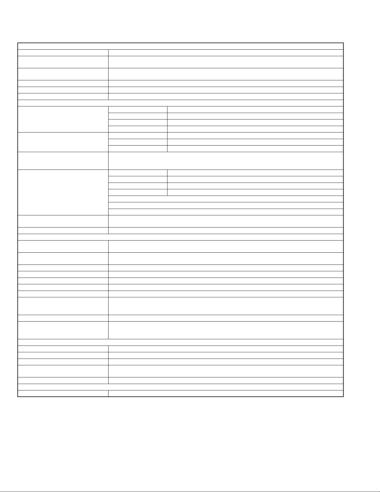
SPECIFICATION
GENERAL
Power requirement AC 220 V - 240 Vd, 50 Hz/60 Hz
Power consumption Power on : 33 W
Temperature Operating : 5°C to 40°C
Operating position Horizontal only
Dimensions (W × H × D) 435 mm × 70 mm × 346 mm
Weight 4.5 kg
VIDEO/AUDIO
Recordable disc DVD-RAM 12 cm : (4.7 GB/9.4 GB)
Recording format DVD-RAM DVD Video Recording format
Recording time Maximum 8 hours (with 4.7 GB disc)
Playable disc DVD-RAM 12 cm : (4.7 GB/9.4 GB)
Audio recording system Dolby Digital (2 ch)
Video recording compression system MPEG2 (CBR/VBR)
Input/Output
S-video input Y : 0.8 - 1.2 Vp-p, 75 Ω
S-video output Y : 1.0 Vp-p, 75 Ω
Video input 0.5 - 2.0 Vp-p, 75 Ω (pin jack)
Video output 1.0 Vp-p, 75 Ω (pin jack)
Audio input -8 dB, 50 kΩ (pin jack) Corresponding to mono (left)
Audio output -8 dB, 1 kΩ (pin jack)
Component video output Y : 1.0 Vp-p, 75 Ω
Optical -18 dBm, 660 nm
Coaxial 0.5Vp-p,75ohms Corresponding to Dolby Digital and DTS Digital Surround
TUNER/TIMER
Signal system PAL-type colour signal and CCIR monochrome signal, 625 lines 50 fields
TV channel storage capacity 99 positions (+AUX position)
Tuning system Frequency synthesized tuner
Channel coverage VHF 47 MHz - 89 MHz/104 MHz - 300 MHz/302MHz-470MHz
Memory backup time Approx. 60 min.
ACCESSORIES
Provided accessories RF cable, 21-pin SCART cable, Satellite Controller, Infrared remote control unit, "R6" battery × 2
Specifications shown are for SP mode unless otherwise specified.
E.& O.E. Design and specifications subject to change without notice.
Power off : 17.6 W
Storage : -20°C to 60°C
DVD-RAM 8 cm : (1.4 GB/2.8 GB)
DVD-R 12 cm:( 4.7 GB, 8 cm: 1.4 GB for General Ver. 2.0)
DVD-RW 4.7 GB for Ver. 1.0/1.1
DVD-R DVD-Video format
DVD-RW DVD-Video format, DVD Video Recording format
(XP) : Approx. 1 hour, (SP) : Approx. 2 hours, (LP) : Approx. 4 hours, (EP) : Approx. 6 hours, (FR) :
Approx. 1 hour - 8 hours
DVD-RAM 8 cm : (1.4 GB/2.8 GB)
DVD-R 12 cm:( 4.7 GB, 8 cm: 1.4 GB for General Ver. 2.0)
DVD VIDEO, DVD-RW 4.7 GB
Music CD (CD-DA)
Video CD
CD-R/RW (CD-DA, Video CD/SVCD formatted discs)
Linear PCM (XP mode only)
C : 0.2 - 0.4 Vp-p, 75 Ω
C : 0.3 Vp-p, 75 Ω
i.Link 4-pin for DV input
PB/PR : 0.7 Vp-p, 75 Ω
Corresponding to copy protection
Bit stream
Selectable in digital audio output setting menu
UHF 470 MHz - 862 MHz
1-2 (No.XA020)
Page 3
SECTION 1
PRECAUTION
1.1 Safety Precautions
(1) This design of this product contains special hardware and
many circuits and components specially for safety purposes. For continued protection, no changes should be made
to the original design unless authorized in writing by the
manufacturer. Replacement parts must be identical to
those used in the original circuits. Services should be performed by qualified personnel only.
(2) Alterations of the design or circuitry of the product should
not be made. Any design alterations of the product should
not be made. Any design alterations or additions will void
the manufacturers warranty and will further relieve the
manufacture of responsibility for personal injury or property
damage resulting therefrom.
(3) Many electrical and mechanical parts in the products have
special safety-related characteristics. These characteristics are often not evident from visual inspection nor can the
protection afforded by them necessarily be obtained by using replacement components rated for higher voltage, wattage, etc. Replacement parts which have these special
safety characteristics are identified in the Parts List of Service Manual. Electrical components having such features
are identified by shading on the schematics and by ( ) on
the Parts List in the Service Manual. The use of a substitute
replacement which does not have the same safety characteristics as the recommended replacement parts shown in
the Parts List of Service Manual may create shock, fire, or
other hazards.
(4) The leads in the products are routed and dressed with ties,
clamps, tubings, barriers and the like to be separated from
live parts, high temperature parts, moving parts and/or
sharp edges for the prevention of electric shock and fire
hazard. When service is required, the original lead routing
and dress should be observed, and it should be confirmed
that they have been returned to normal, after reassembling.
(5) Leakage shock hazard testing
After reassembling the product, always perform an isolation check on the exposed metal parts of the product (antenna terminals, knobs, metal cabinet, screw heads,
headphone jack, control shafts, etc.) to be sure the product
is safe to operate without danger of electrical shock.Do not
use a line isolation transformer during this check.
• Plug the AC line cord directly into the AC outlet. Using a
"Leakage Current Tester", measure the leakage current
from each exposed metal parts of the cabinet, particularly any exposed metal part having a return path to the
chassis, to a known good earth ground. Any leakage current must not exceed 0.5mA AC (r.m.s.).
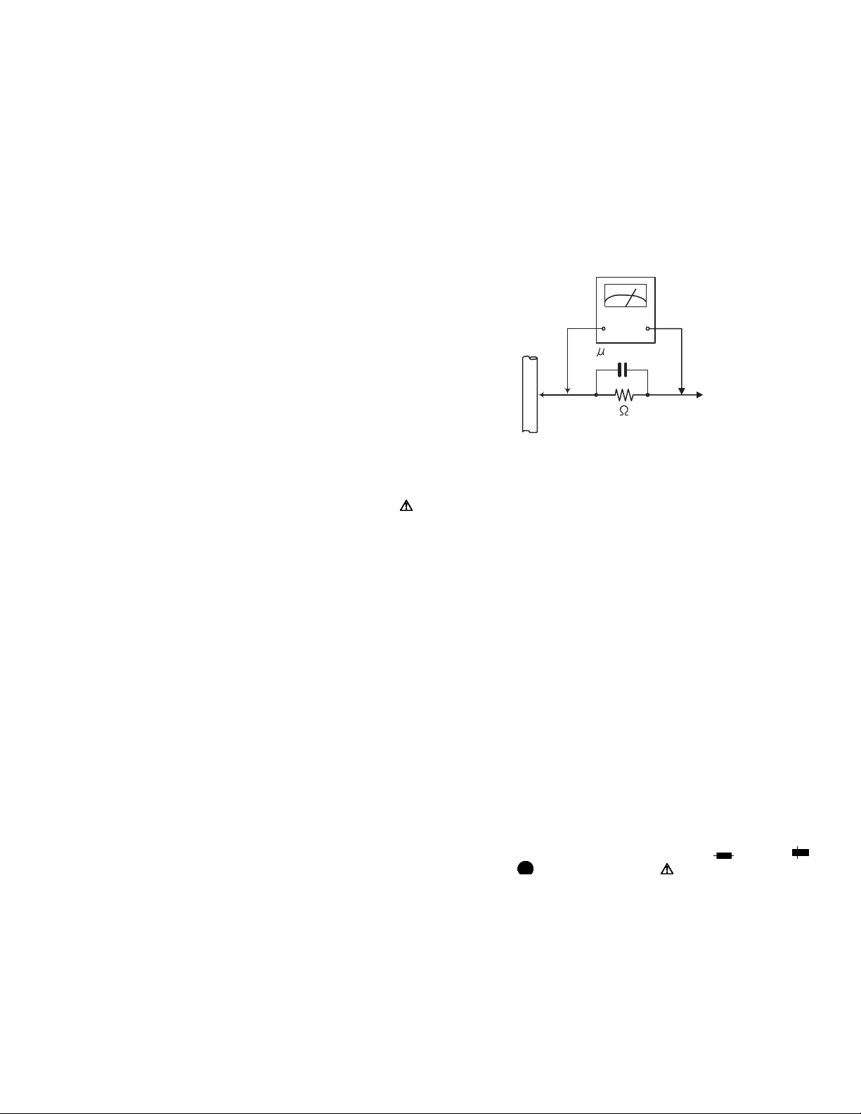
• Alternate check method
Plug the AC line cord directly into the AC outlet. Use an
AC voltmeter having, 1,000Ω per volt or more sensitivity
in the following manner. Connect a 1,500Ω 10W resistor
paralleled by a 0.15µF AC-type capacitor between an exposed metal part and a known good earth ground.
Measure the AC voltage across the resistor with the AC
voltmeter.
Move the resistor connection to each exposed metal
part, particularly any exposed metal part having a return
path to the chassis, and measure the AC voltage across
the resistor. Now, reverse the plug in the AC outlet and
repeat each measurement. Voltage measured any must
not exceed 0.75 V AC (r.m.s.). This corresponds to 0.5
mA AC (r.m.s.).
AC VOLTMETER
(Having 1000
ohms/volts,
or more sensitivity)
0.15 F AC TYPE
Place this
probe on
1500 10W
Good earth ground
1.2 Warning
(1) This equipment has been designed and manufactured to
meet international safety standards.
(2) It is the legal responsibility of the repairer to ensure that
these safety standards are maintained.
(3) Repairs must be made in accordance with the relevant
safety standards.
(4) It is essential that safety critical components are replaced
by approved parts.
(5) If mains voltage selector is provided, check setting for local
voltage.
1.3 Caution
Burrs formed during molding may be left over on some parts
of the chassis.
Therefore, pay attention to such burrs in the case of preforming repair of this system.
1.4 Critical parts for safety
In regard with component parts appearing on the silk-screen
printed side (parts side) of the PWB diagrams, the parts that are
printed over with black such as the resistor ( ), diode ( )
and ICP ( ) or identified by the " " mark nearby are critical
for safety. When replacing them, be sure to use the parts of the
same type and rating as specified by the manufacturer.
(This regulation dose not Except the J and C version)
each exposed
metal part.
(No.XA020)1-3
Page 4
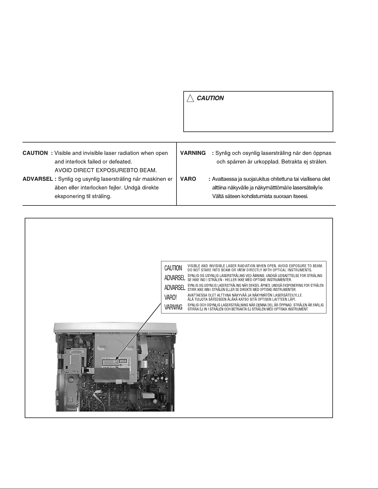
1.5 Important for laser products
!
1.CLASS 1 LASER PRODUCT
2.DANGER : Invisible laser radiation when open and inter
lock failed or defeated. Avoid direct exposure to beam.
3.CAUTION : There are no serviceable parts inside the
Laser Unit. Do not disassemble the Laser Unit. Replace
the complete Laser Unit if it malfunctions.
4.CAUTION : The CD,MD and DVD player uses invisible
laser radiation and is equipped with safety switches which
prevent emission of radiation when the drawer is open and
the safety interlocks have failed or are defeated. It is
dangerous to defeat the safety switches.
5.CAUTION : If safety switches malfunction, the laser is able
to function.
6.CAUTION : Use of controls, adjustments or performance of
procedures other than those specified here in may result in
hazardous radiation exposure.
Please use enough caution not to
see the beam directly or touch it
in case of an adjustment or operation
check.
REPRODUCTION AND POSITION OF LABEL and PRINT
WARNING LABEL and PRINT
On mechaism assembly
1-4 (No.XA020)
Page 5

SECTION 2
SPECIFIC SERVICE INSTRUCTIONS
This service manual does not describe SPECIFIC SERVICE INSTRUCTIONS.
(No.XA020)1-5
Page 6

SECTION 3
TOP COVER
Hook b
DISASSEMBLY
3.1 Main body section
3.1.1 Remove the top cover (See figure 1)
(1) Remove the four screws A attaching the top cover on both
sides of the main body.
(2) Remove the five screws B attaching the top cover on the
back of the main body.
(3) Raise the both sides and lower part of the rear of the top
cover, with opening them slightly in an outward direction.
And the top cover will be removed.
3.1.2 Remove the front panel assembly (See figure 2, figure 3, and figure 4)
• Prior to performing the following procedure, remove the top
cover.
• There is no need to remove the mechanism assembly.
(1) Disconnect the card wires from connector
CN3002, CN4001 on the main board.
(2) Hooks a and b are removed respectively, and the front
panel assembly is removed.
NOTE:
In case of attach a front panel assembly, please let a
card wire pass in the hole in the front part of a chassis,
respectively, and connect.
CN3002CN4001 CN3001
CN3001
,
A x 2
Front panel
assembly
A x 2
TOP COVER
TOP COVER
B
Fig.1
Hook b
B
B
B
B
Hook a
1-6 (No.XA020)
Main board
Fig.2
Hook a
Chassis of front part
Fig.3
Front panel
assembly
Fig.4
Card wireCard wire
Card wire
Page 7

3.1.3 Remove the mechanism assembly (See figure 5)
• Prior to performing the following procedure, remove the top
cover.
• There is no need to remove the front panel assembly.
(1) Disconnect the socket wire from connector
power supply board.
(2) Disconnect the card wire from connector
module board.
(3) Remove the four screws C attaching the mechanism as-
sembly.
3.1.4 Remove the module board (See figure 6, figure 7)
• Prior to performing the following procedure, remove the top
cover.
(1) Disconnect the card wire from connector
module board.
(2) Remove the four screws D and E attaching the module
board.
(3) Remove the one screw F attaching the DV terminal board.
(4) Lift the module board up, and remove it. Then, the module
board is removed from the connectors
on the main board. In attaching the module board, insert
the connector on the module board in these connectors se-
curely.
CN5303
CN2201 on the
CN2201
CN4101
on the
on the
, CN4102
Module board
CN2201 C C CN5303
DV terminal
board
D
Mechanism assembly
C
Fig.5
EF
C
D
Module board
EModule board
CN2201
Fig.6
CN4102
Main boardCN4101
Fig.7
(No.XA020)1-7
Page 8

3.1.5 Remove the power supply board (See figure 8)
• Prior to performing the following procedure, remove the top
cover.
(1) Disconnect the card wire from connector
power supply board.
(2) Disconnect the socket wire from connector
CN5303, CN5305 on the power supply board.
(3) Disconnect the power cord from connector
power supply board.
(4) Remove the two screws G attaching the power supply
board.
(5) Four fasteners are removed.
3.1.6 Remove the main board (See figure 9, figure 10)
• Prior to performing the following procedure, remove the top
cover, mechanism assembly, module board.
(1) Disconnect the card wire from connector CN3001
CN3002, CN4001, CN5101, CN7301 on the main board
(2) Disconnect the socket wire from connector
power supply board.
(3) Remove the two screws H attaching the main board.
(4) Remove the seven screws I attaching the rear panel with
main board.
CN5301 on the
CN5302,
CN5001 on the
CN5302 on the
CN5302
Fastener
Power supply
board
Fastener
CN5301
CN5303
Fastener
G
CN5001
Power cord
CN5305
Fig.8
CN3002CN4001
,
G
CN5302CN3001H
CN5101
H CN7301
Main board
I
Power supply board
Fig.9
Rear panel
Fig.10
1-8 (No.XA020)
Page 9

SECTION 4
ADJUSTMENT
4.1 Timer clock adjustment (for only ver.E)
If an error comes to arise for a clock, the following procedure will adjust.
Signal (A1) No signal
Mode (B) EE
Equipment (C) Frequency counter
Measuring point (D1)
Adjustment part (F) C3025 (TIMER CLOCK)
Specified value (G1) 1024.008 ±0.001 Hz
(1) Connect the frequency counter to the measuring point (D1).
(2) Connect the short wire between the short point (D2) and Vcc (5V).
(3) Short the leads of capacitor (D3) once in order to reset the microprocessor of the system controller.
(4) Disconnect the short wire between the short point (D2) and Vcc then connect it again.
(5) Adjust the Adjustment part (F) so that the output frequency becomes the specified value (G).
IC3001 pin 61
IC3001 pin 17
(D2)
(D3)
C3026 + and -
(976.5549 ±0.0010 usec)
(No.XA020)1-9
Page 10

SECTION 5
TROUBLESHOOTING
5.1 JIG Mode
The following remote control units are required to set and cancel JIG mode.
For setting : a remote control unit attached to product.
For cancellation : JIG remote control unit (part number : PTU94023B)
Remote control unit
attached to product
CABLE/DBS
DVDTV
STANDBY/ON
TV
TV/
DVD
TV/CBL/DBS
MUTING
VIDEO
TV VOLUME
DEF
ABC
JKLGHI MNO
CH
TUVPQRS WXYZ
DBS
AUXCANCEL
MEMO/MARK
TIMER
REC LINK
PROG/CHECK
VCR Plus+
NAVIGATIONTOP MENU
ENTER
RETURN
MENU
NEXTPREVIOUS
SLOWSLOW PLAY/SELECT
CLEAR
STOP/
PAUSEREC
REC MODE LIVE CHECK
OPEN/
CLOSE
SET UP DISPLAY
ON SCREEN
PROGRESSIVE
AUDIO SUBTITLE ANGLE
SCAN
JIG remote control unit
JIG remote control unit
[Data transmission]
Set the data code,
and then press the
" " button.
3
Custom code
43:A Code
53:B Code
6F:C Code
7F:D Code
Data code
Initial mode
When the main body is set to JIG mode and when the main body is under JIG mode, the remote control unit attached to product operates only in "Remote Control Code 1". Since main body is in "Remote Control Code 3" when it is shipped and just after its batteries
are changed, "Remote Control Code 3" needs to be changed to "Remote Control Code 1."
< Changing Remote Control Code >
(1) Switch TV/CABLE/DBS/DVD Switch to "DVD"
(2) Press the numeric button "1" of the remote control unit while pressing the "SET UP" button of the remote control unit. Then,
press the "ENTER" button, and then release the "SET UP" button.
(3) Press the "PLAY" button of the main body for five seconds or longer while the main body is in stand-by mode, and a current
remote control code of the main body is displayed in FL indicator of the main body.
(4) While keeping the state of (3), press the "STOP" button of the remote control unit toward the main body.
(5) When FL indicator displays "DVD1," it means that the Remote Control Code has been changed to "1."
*This product has remote control codes of 1, 2, 3, and 4.
*The remote control codes "DVD 1, 2, 3, and 4" of product are the same as the remote control codes
"A, B, C, and D" of video cassette recorders manufactured in JVC.
1-10 (No.XA020)
TV
TV/
MUTING
VIDEO
ABC
JKLGHI MNO
TUVPQRS WXYZ
DBS
AUXCANCEL
PROG/CHECK
VCR Plus+
MENU
STOP/
REC MODE LIVE CHECK
SET UP DISPLAY
AUDIO SUBTITLE ANGLE
ENTER
TV/CBL/DBS
DEF
MEMO/MARK
REC LINK
CLEAR
ON SCREEN
CABLE/DBS
STANDBY/ON
NAVIGATIONTOP MENU
RETURN
SLOWSLOW PLAY/SELECT
PROGRESSIVE
TV VOLUME
NEXTPREVIOUS
PAUSEREC
CLOSE
DVDTV
(1)
DVD
"(2) a-c" shows the order of pressing the buttons.
(2)b
CH
TIMER
(3),(5)
(3)
(2)c
(4)
OPEN/
(2)a
STANDBY/ON
SCAN
DVD 1
F1
S-VIDEO VIDEO
SAT
L(MONO)-AUDIO-R
REC MODE
PULL - OPEN
DV
DV IN
Page 11

5.1.1 Setting JIG mode
To display SYSTEM INFO or to upgrade firmware, the main body needs to be set to JIG mode.
(1) Turn the main body ON.
(2) Press the buttons of the remote control unit attached to product in the following order : "SET UP" → "2" → "8" → "ENTER"
(3) When a colon ":" between "hour" and "minute" of a clock in FL indicator blink, it means that the main body has been set to JIG
mode properly.
[ Example ]
Not in JIG mode In JIG mode
15 : 07
15 07
A colon blinks.
(4) Turn the main body OFF, and then turn it ON again.
*Once the main body is set to JIG mode, the JIG mode cannot be cancelled even if the power cord is pulled out from the wall
socket.
CABLE/DBS
DVDTV
STANDBY/ON
TV
TV/
DVD
TV/CBL/DBS
MUTING
VIDEO
ABC
JKLGHI MNO
TUVPQRS WXYZ
DBS
AUXCANCEL
PROG/CHECK
VCR Plus+
MENU
STOP/
REC MODE LIVE CHECK
SET UP DISPLAY
AUDIO SUBTITLE ANGLE
TV VOLUME
DEF
(2)b
CH
(2)c
MEMO/MARK
TIMER
REC LINK
NAVIGATIONTOP MENU
ENTER
(2)d
RETURN
NEXTPREVIOUS
SLOWSLOW PLAY/SELECT
CLEAR
PAUSEREC
OPEN/
ON SCREEN
CLOSE
(2)a
PROGRESSIVE
SCAN
"(2) a-d" shows the order of pressing the buttons.
(1),(4)
STANDBY/ON
(3)
15:07
F1
S-VIDEO VIDEO
SAT
L(MONO)-AUDIO-R
REC MODE
PULL - OPEN
DV
DV IN
5.1.2 Canceling JIG mode
(1) Transmit "43-9D" to the main body by using JIG remote control unit.
(2) A colon ":" between "hour" and "minute" of a clock in FL indicator light.
(3) Turn the main body OFF, and then turn it ON again.
NOTE:
After repair work, be sure to cancel JIG mode. Before returning product to a user, confirm that a colon ":" between "hour" and
"minute" of a clock in FL indicator light.
(No.XA020)1-11
Page 12

5.1.3 Displaying SYSTEM INFO
SYSTEM INFO contains information on firmware version of the main body and the mechanism drive, and an initialize execution menu.
(1) Set the main body to JIG mode.
(2) Transmit "43-8B" to the main body by using JIG remote control unit.
(3) SYSTEM INFO menu is displayed in the television screen.
(4) To move cursor in SYSTEM INFO, use the "", "", "", and "" buttons of a remote control unit attached to product.
< VERSION >
SYSTEM INFO
VERSION INITIALIZE INFORMATION
CPRM Key Download
C-Ware / A-Ware
JVRI / Host
1394 / OSD
Analog / BE-R / FE-R
EXIT
SET UP
ENTER
SELECT WITH [CURSORS]
THEN PRESS [ENTER]
SELECT
Done
PROD98-2 / JVC_43
0076 / V0108
0053E / MTEN03
003 / 2 / 2
Version of firmware
This part is updated after the firmware of the
main body is upgraded.
System controller version
/ Region code (Backend) / Region code (Frontend)
NOTE :
Items other than the ones described above are not used in service work.
(5) To quit the SYSTEM INFO menu, transmit "43-8B" to the main body by using JIG remote control unit.
(6) Cancel JIG mode.
5.1.4 Upgrading firmware of the main body
• Firmware upgrade disk supports CD-R media.
(1) Download a compressed file of the latest firmware in "optical disc" page in JS-NET.
(2) Decompress the file, and a file "fwupdate.bin" is generated.
(3) Write "fwupdate.bin" in CD-R in ISO9660 format.(Don’t use Packet Write software. Write in UDF format.)
(4) Set the main body to JIG mode.
(5) Transmit "43-70" to the main body by using JIG remote control unit.
(6) "UPDATE" appears in FL indicator. Load disk for upgrade on the tray, and close the tray.
(7) Upgrade processing is started automatically.
(8) Then, "FW UPDATE" appears in FL indicator. It takes approx. 6 minutes at maximum to upgrade firmware.
(9) The tray is ejected. Then, take out the disk and close the tray.
(10) Turn the main body OFF, and pull out the power cord from the wall socket. Then, plug the power cord into the wall socket.
(11) "LOADING" of FL indicator disappears. Then, turn the main body ON.
(12) Display the SYSTEM INFO menu, and check the version of the firmware.
(13) Cancel JIG mode.
ATTENTION :
Firmware may sometimes not be upgraded successfully.
If firmware is not upgraded successfully, the tray opens, and "ERROR" appears in FL indicator.
If firmware is upgraded successfully, the tray opens, and "OPEN" appears in FL indicator.
If the power cord is pulled out from the wall socket while "ERROR" appears, data in the flash memory is destroyed and the main
body cannot start: the flash memory needs to be replaced.
After upgrading procedure, pay enough attention to FL indicator when the tray opens.
When "ERROR" appears, upgrade firmware again in the following way to restore the firmware.
(1) Transmit "43-70" to the main body by using JIG remote control unit while the tray opens.
(2) When "UPDATE" appears in FL indicator, close the tray and make the main body read the disk. Upgrading starts.
(3) After (2), perform upgrading procedure (4) - (10) of 5.1.4 Upgrading firmware of the main body above.
1-12 (No.XA020)
Page 13

5.2 The setting method of a region code
A region code should be set after a DVD recorder mechanism unit is replaced.
While a DVD recorder mechanism unit is in a warehouse as a stock, a region code of the drive unit is not determined.
Only replacement of a DVD recorder mechanism unit may cause abnormal playback of Disc.
Set a region code of a DVD recorder mechanism unit in the following procedure.
(1) Replace a DVD recorder mechanism unit.
(2) Turn POWER switch of the unit ON.
(3) Set the main body to JIG mode.
(4) Insert a DVD-RAM disc in the unit to make the unit read the DVD-RAM disc.(The DVD-RAM disk used in this procedure is not a
disk for upgrade. If it is a DVD-RAM disk, it is good anything.)
(5) Send "43-F2" to the unit by using JIG remote control unit.
(6) "REGION 2" is displayed on FL display.
(7) Set the unit to STANDBY.
(8) Turn the POWER switch ON.
(9) To cancel JIG MODE, send "43-9D" to the unit by using JIG remote control unit.
(10) Colon is displayed on a clock on FL display.
(11) Setting is completed in the procedure above.
5.3 Taking out a disc
5.3.1 Method 1
(1) AC Plug is pulled out at once and inserted again.
(2) It is displayed on FL display as "LOADING", and while it blinks, pushing the EJECT button of a main body is continued.
(3) After a while, a tray opens (About 20 seconds).
(4) A disk is removed, the EJECT button of a main body is pushed, and a tray is made to close.
(5) The "LOADING" blink display of FL display disappears and it will be in a standby state.
(6) If the POWER button is pushed, it will usually be operating.
5.3.2 Method 2
When a disk is not able to be taken out by operation of "Method 1", a front door is opened manually, and the EJECT button in the lower
right of a DVD recorder mechanism is pushed directly.
5.3.3 Method 3
A Disc can be taken out manually even when the main body is turned off.
(1) Open the front door.
(2) Pass a thin wire through a hole in the DVD recorder mechanism unit.
(3) The disc tray comes out slightly. Take out the disc tray manually.
DVD recorder mechanism unit
Front door Hole
5.4 The exchange method of a tray fitting
Disc tray
When DVD recorder mechanism unit is exchanged, please transplant a tray fitting from an old drive, or change for a new tray fitting.
A tray is pulled out manually, as shown in a figure, it carries out, and a tray fitting is removed.
Tr ay
Tray fitting
DVD recorder mechanism unit
Direct EJECT button
(No.XA020)1-13
Page 14

VICTOR COMPANY OF JAPAN, LIMITED
AV & MULTIMEDIA COMPANY OPTICAL DISC CATEGORY 1644, Shimotsuruma, Yamato, Kanagawa 242-8514, Japan
(No.XA020)
Printed in Japan
WPC
 Loading...