

Page 1
SERVICE MANUAL
DVD VIDEO RECORDER
YD05820053
DR-M100SUS, DR-M100SUC,
DR-M100SUJ
Area Suffix
US ---------------- U.S.A.
UC -------------- Canada
UJ ------- U.S.A Militaly
R
+
STANDBY/ON
Since the whole mechanism assembly unit is replaced, the DVD recorder
mechanism of this unit need not be adjusted.
RAM/RW
DR-M100SUS, DR-M100SUC, DR-M100SUJ [D5R10]
CH
PUSH-OPEN
-
CH
TABLE OF CONTENTS
1 PRECAUTION. . . . . . . . . . . . . . . . . . . . . . . . . . . . . . . . . . . . . . . . . . . . . . . . . . . . . . . . . . . . . . . . . . . . . . . . . 1-3
2 SPECIFIC SERVICE INSTRUCTIONS . . . . . . . . . . . . . . . . . . . . . . . . . . . . . . . . . . . . . . . . . . . . . . . . . . . . . . 1-7
3 DISASSEMBLY . . . . . . . . . . . . . . . . . . . . . . . . . . . . . . . . . . . . . . . . . . . . . . . . . . . . . . . . . . . . . . . . . . . . . . . 1-8
4 ADJUSTMENT . . . . . . . . . . . . . . . . . . . . . . . . . . . . . . . . . . . . . . . . . . . . . . . . . . . . . . . . . . . . . . . . . . . . . . . 1-14
5 TROUBLESHOOTING . . . . . . . . . . . . . . . . . . . . . . . . . . . . . . . . . . . . . . . . . . . . . . . . . . . . . . . . . . . . . . . . . 1-15
COPYRIGHT © 2005 Victor Company of Japan, Limited
No.YD058
2005/3
Page 2
SPECIFICATION
DR-M100SUS,DR-M100SUC DR-M100SUJ
GENERAL
Power requirement AC 120 V~, 60 Hz AC 220 V-240 V~,50/60 Hz
Power consumption Power on : 30 W
Temperature Operating : 5°C to 35°C(41°F to 95°F)
Operating position Horizontal only
Dimensions (W × H × D) 435 mm × 70 mm × 300 mm (17-3/16" x 2-11/16" x 11-13/16")
VIDEO/AUDIO
Recordable disc
Recording format DVD-RAM : DVD Video Recording format
Recording time Maximum 8 hours (with 4.7 GB disc)
Audio recording system Dolby Digital (2 ch)
Video recording compression system
Input/Output
S-video input Y:1.0 Vp-p, 75 ohms
S-video output Y : 1.0 Vp-p, 75 ohms
Video input 1.0 Vp-p, 75 ohms (pin jack)
Video output 1.0 Vp-p, 75 ohms (pin jack)
Audio input 2Vrms (pin jack)
Audio output 2Vrms (pin jack)
Component video output Y : 1.0 Vp-p, 75 ohms
Digital audio output Coaxial
TUNER/TIMER
Tuning system Frequency synthesized tuner
Channel coverage VHF: Channels 2 - 13
Clock reference Quartz
Program capacity 30 days programmable timer/8 programs
Memory backup time Approx. 5 sec.
ACCESSORIES
Provided accessories RF cable, Audio/video cable, Infrared remote control unit,
Specifications shown are for SP mode unless otherwise specified. E. & O.E. Design and specifications subject to change without notice.
• Manufactured under licence from Dolby Laboratories. “Dolby” and double-D symbol are trademarks of Dolby Laboratories.
• “DTS” and “DTS DIGITAL OUT “ are trademarks of Digital Theater Systems, Inc.
• VCR Plus+ and PlusCode are registered trademarks of Gemstar Development Corporation.
The VCR Plus+ system is manufactured under license from Gemstar Development Corporation.
TM
• DSS
• This product incorporates copyright protection technology that is protected by method claims of certain U.S. patents and other intellectual property
is an official trademark of DIRECTV, Inc., a unit of GM Hughes Electronics. DISH NetworkTM is a trademark of Echostar Communications
Corporation.
rights owned by Macrovision Corporation and other rights owners. Use of this copyright protection technology must be authorized by Macrovision
Corporation, and is intended for home and other limited viewing users only unless otherwise authorized by Macrovision Corporation. Reverse engineering or disassembly is prohibited.
Power off : 2.7 W
Storage : -20°C to 60°C(-4°F to 140°F)
Weight 3.4 kg (7.5 lbs)
DVD-RAM 12 cm (4.7 GB/9.4 GB)
DVD-RAM 8 cm (1.4 GB/2.8 GB)
DVD-R 12 cm(4.7 GB)
DVD-R 8 cm(1.4 GB)
DVD-RW 12 cm(4.7 GB)
DVD-RW 8 cm(1.4 GB)
DVD-R : DVD-Video format
DVD-RW : DVD-Video format, DVD Video Recording format
(XP) : Approx. 1 hour
(SP) : Approx. 2 hours
(LP) : Approx. 4 hours
(EP) : Approx. 6 hours
(FR) : Approx. 1 hour - 8 hours
Linear PCM (XP mode only)
MPEG2 (CBR/VBR)
C : 0.286 Vp-p, 75 ohms
C : 0.3 Vp-p, 75 ohms
i.Link 4-pin for DV input
PB/PR: 0.7 Vp-p, 75 ohms
Corresponding to copy protection
Corresponding to Dolby Digital and DTS Digital Surround
Bit stream
Selectable in digital audio output setting menu
UHF: Channels 14 - 69
CATV: 113 Channels
”AA” battery x 2
Power on : 29 W
Power off : 5.2 W
RF cable, Audio/video cable, Infrared remote control unit,
”AA” battery x 2, Conversion pliug
1-2 (No.YD058)
Page 3
SECTION 1
PRECAUTION
1.1 Safety Precautions
(1) This design of this product contains special hardware and
many circuits and components specially for safety purposes. For continued protection, no changes should be made
to the original design unless authorized in writing by the
manufacturer. Replacement parts must be identical to
those used in the original circuits. Services should be performed by qualified personnel only.
(2) Alterations of the design or circuitry of the product should
not be made. Any design alterations of the product should
not be made. Any design alterations or additions will void
the manufacturers warranty and will further relieve the
manufacture of responsibility for personal injury or property
damage resulting therefrom.
(3) Many electrical and mechanical parts in the products have
special safety-related characteristics. These characteristics are often not evident from visual inspection nor can the
protection afforded by them necessarily be obtained by using replacement components rated for higher voltage, wattage, etc. Replacement parts which have these special
safety characteristics are identified in the Parts List of Service Manual. Electrical components having such features
are identified by shading on the schematics and by ( ) on
the Parts List in the Service Manual. The use of a substitute
replacement which does not have the same safety characteristics as the recommended replacement parts shown in
the Parts List of Service Manual may create shock, fire, or
other hazards.
(4) The leads in the products are routed and dressed with ties,
clamps, tubings, barriers and the like to be separated from
live parts, high temperature parts, moving parts and/or
sharp edges for the prevention of electric shock and fire
hazard. When service is required, the original lead routing
and dress should be observed, and it should be confirmed
that they have been returned to normal, after reassembling.
(5) Leakage shock hazard testing
After reassembling the product, always perform an isolation check on the exposed metal parts of the product (antenna terminals, knobs, metal cabinet, screw heads,
headphone jack, control shafts, etc.) to be sure the product
is safe to operate without danger of electrical shock.Do not
use a line isolation transformer during this check.
• Plug the AC line cord directly into the AC outlet. Using a
"Leakage Current Tester", measure the leakage current
from each exposed metal parts of the cabinet, particularly any exposed metal part having a return path to the
chassis, to a known good earth ground. Any leakage current must not exceed 0.5mA AC (r.m.s.).
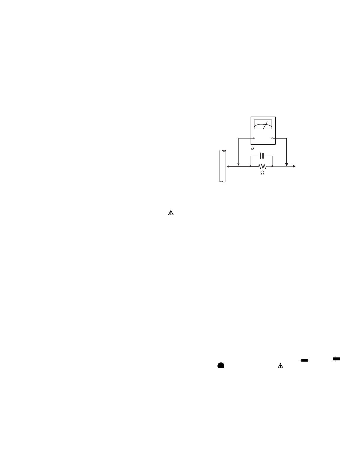
• Alternate check method
Plug the AC line cord directly into the AC outlet. Use an
AC voltmeter having, 1,000Ω per volt or more sensitivity
in the following manner. Connect a 1,500Ω 10W resistor
paralleled by a 0.15µF AC-type capacitor between an ex-
posed metal part and a known good earth ground.
Measure the AC voltage across the resistor with the AC
voltmeter.
Move the resistor connection to each exposed metal
part, particularly any exposed metal part having a return
path to the chassis, and measure the AC voltage across
the resistor. Now, reverse the plug in the AC outlet and
repeat each measurement. Voltage measured any must
not exceed 0.75 V AC (r.m.s.). This corresponds to 0.5
mA AC (r.m.s.).
AC VOLTMETER
(Having 1000
ohms/volts,
or more sensitivity)
0.15 F AC TYPE
Place this
probe on
1500 10W
Good earth ground
1.2 Warning
(1) This equipment has been designed and manufactured to
meet international safety standards.
(2) It is the legal responsibility of the repairer to ensure that
these safety standards are maintained.
(3) Repairs must be made in accordance with the relevant
safety standards.
(4) It is essential that safety critical components are replaced
by approved parts.
(5) If mains voltage selector is provided, check setting for local
voltage.
1.3 Caution
Burrs formed during molding may be left over on some parts
of the chassis.
Therefore, pay attention to such burrs in the case of preforming repair of this system.
1.4 Critical parts for safety
In regard with component parts appearing on the silk-screen
printed side (parts side) of the PWB diagrams, the parts that are
printed over with black such as the resistor ( ), diode ( )
and ICP ( ) or identified by the " " mark nearby are critical
for safety. When replacing them, be sure to use the parts of the
same type and rating as specified by the manufacturer.
(This regulation dose not Except the J and C version)
each exposed
metal part.
(No.YD058)1-3
Page 4
1.5 Preventing static electricity
Electrostatic discharge (ESD), which occurs when static electricity stored in the body, fabric, etc. is discharged, can destroy the laser
diode in the traverse unit (optical pickup). Take care to prevent this when performing repairs.
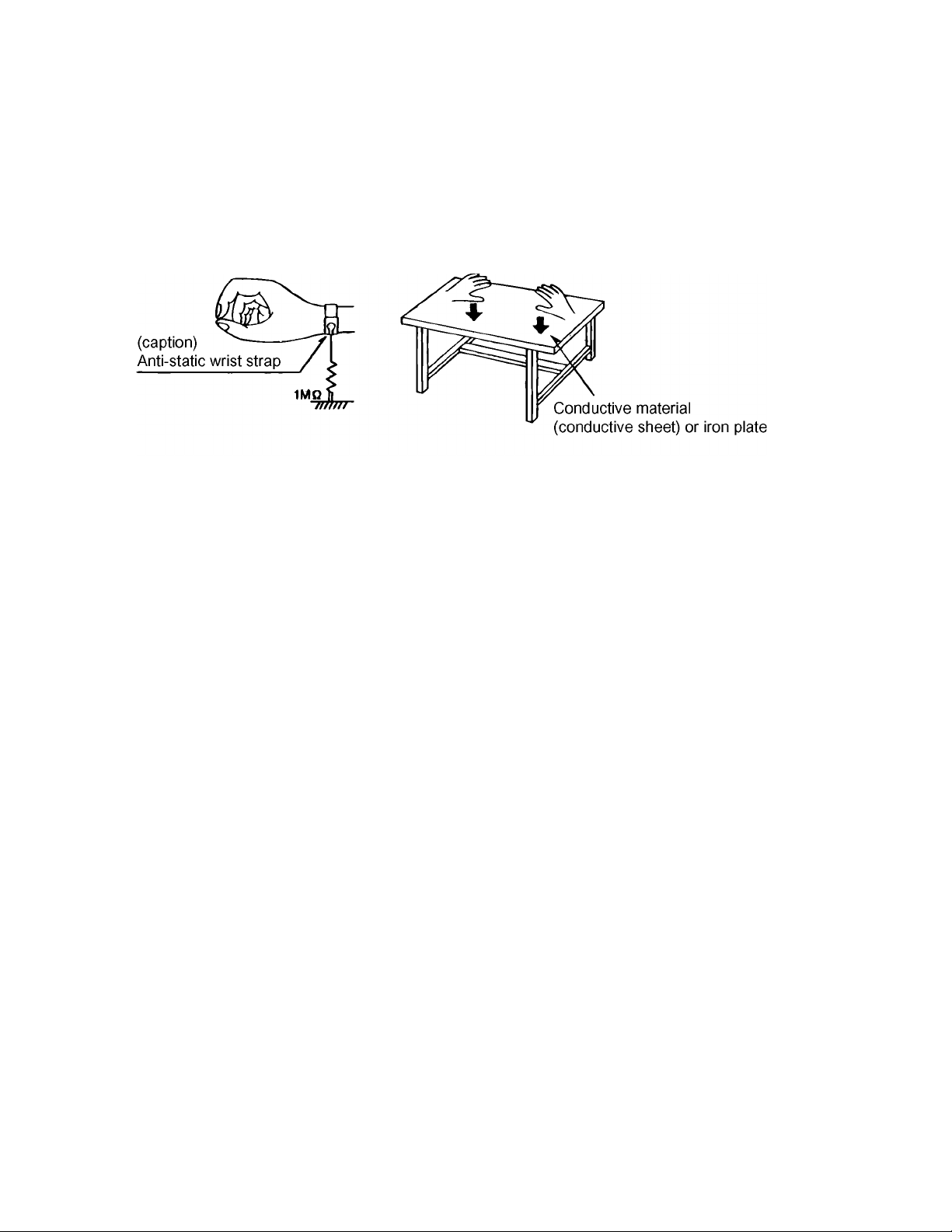
1.5.1 Grounding to prevent damage by static electricity
Static electricity in the work area can destroy the optical pickup (laser diode) in devices such as DVD players or recorder.
Be careful to use proper grounding in the area where repairs are being performed.
(1) Ground the workbench
Ground the workbench by laying conductive material (such as a conductive sheet) or an iron plate over it before placing the
traverse unit (optical pickup) on it.
(2) Ground yourself
Use an anti-static wrist strap to release any static electricity built up in your body.
(3) Handling the optical pickup
• In order to maintain quality during transport and before installation, both sides of the laser diode on the replacement optical
pickup are shorted. After replacement, return the shorted parts to their original condition.
(Refer to the text.)
• Do not use a tester to check the condition of the laser diode in the optical pickup. The tester's internal power source can easily
destroy the laser diode.
1.6 Handling the traverse unit (optical pickup)
(1) Do not subject the traverse unit (optical pickup) to strong shocks, as it is a sensitive, complex unit.
(2) Cut off the shorted part of the flexible cable using nippers, etc. after replacing the optical pickup. For specific details, refer to the
replacement procedure in the text. Remove the anti-static pin when replacing the traverse unit. Be careful not to take too long
a time when attaching it to the connector.
(3) Handle the flexible cable carefully as it may break when subjected to strong force.
(4) I t is not possible to adjust the semi-fixed resistor that adjusts the laser power. Do not turn it.
1-4 (No.YD058)
Page 5
1.7 Important for laser products
Importance administering point on the safety
W1613
W253
CN3002
W1614
W1415
CN4001
W262
CN4101CN4102
W241
W1018
W1407
W222
W832
W1010
W604
W811
CN3003
W220
L6033
TU6001
W249
B5508
W2203
W2809
W829
C8202
C8212
W1811
W1808
C8210
W1017
W1807
CN4103
W223
W221
C6516
C6520
C6515
C6519
W219
C6510
L6501
L6032
CF6031
W217
W1401
W1002
L6004
C6005
D6002
W213
GN1
L6001
C6007
W601
J4106
W251
GN2
C8027
C8025
C8023
W821
W1020
C8021
C6523
W1210
C6522
C6502
C8022
C8014
W233
W1608
W2003
C6501
C6503
C5329
W214
C8217
J4103 J4104
W2807
C8012
C8010
C8011
W1805
W1604
W1603
W1601
W810
W1204
W805
C8215
W1019
W1016
W2404
C6521
C6505
C6509
C5331
CN5304
W204
J4105
W802
W2205
W1612
W1818
W1820
W1819
W2406
W823
W1809
C8005
C8009
C8008
C8007
W1206
W1207
W1015
W228
W2004
W3003
W3002
W2402
W1403
W2601
W1205
W3001
W1008
W1402
W258
B4111
C4105
C4102
W2201
L4101
C4113
C4111
C4114
C4117
W806
C4112
C8218
W212
W211
W1201
C8216
W209
W208
J4102
W1607
W2407
W1217
W1219
W1216
W1215
W609
W826
W825
W824
W242
W608
W239
W236
W234
W3004
W3006
W3005
W259
C4106
C4124
C4123
W1801
C4119
W803
J4002
W201
W1610
W606
W1013
W1605
W1606
W3012
W2803
W2403
W3010
W3007
W3008
W3009
W2401
W1006
W1804
W1005
W1803
W2001
C4118
C4008
C4125
W1202
W804
W210
W207
W1001
J4003
CN3001
W2207
W2206
W1816
W1817
W610
C3020
W240
X3001
X3002
C3040
W226
W224
W2005
W1014
W1806
W3011
W2805
W2804
W2602
W2802
W2202
W2002
W1223
W1203
W1802
W807
W602
W205
W203
W202
J4101
W801
J7301
W2405
W830
W243
W257
W238
C3030
C3033
W818
C3038
W815
W1609
W2007
W1406
W227
GN3
W252
W605
W812
W1012
W1011
W1009
W1007
W1602
W809
W260
W2801
L4001
W218
C4036
W603
B4002
W216
C4038
W215
Q7201
CN7301
R7204
ST1
D7303
D7304
D7301
J7201
D7302
#PC00029
W263
W255
W1416
W827
L4002
W2204
W250
W612
W831
W828
W1022
W1410
W1611
D3002
W256
W614
B5503
W1212
W1810
W3014
W1208
W1211
W1209
W2806
W1026
W229
W814
W3013
W2006
CP5301
W1404
C5337
CN5302
CN3004
W1004
CN5301
W1003
L7201
W206
C8501
C7202
CN5303
C8503
L8501
C8401
J8501
J8401
W816
C3010
CN3901
W247
W237
C3011
W1411
W2008
W1812
D5314
W819
D5310
B5501
W1408
D5308
D5307
D5311
D5313
C5307
W231
D5312
W230
L5205
W607
W1405
W225
Q5301
R5323
R5319
C5201
D5202
IC5301
C5302
D5208
D5201
C5301
W808
PC5101
R5105
D5103
D5105
D5106
D5104
C5104
C5004
IC5101
C5105
R5001
CN5305
C5319
W613
W254
W833
W813
W3016
C3042
D3003
W2810
W2808
W2605
W1023
D3005
D3004
W1813
D5317
B5505
W1409
D5319
Q5310
C5312
W2603
D5309
C5325
D5318
W817
W232
C5306
D5303
C5305
R5307
D5302
L5203
C5205
C5206
C5202
C5208
W1220
D5205
D5213
D5206
D5209
T5001
W1025
W1024
C5003
D5001
C5103
R5108
IC5309
C5316
C5321
W248
W1414
D5306
GN4
W1413
W1021
W1222
W1815
Q5316
C5209
C5101
W2604
C5318
CP5302
L5204
D5210
CN5001
D5315
W246
C5311
W1214
W1221
W1218
W245
C5310
Q5304
R5320
W244
W1814
D5305
W822
W1213
R5311
R5313
W820
C5303
D5304
Q5307
W834
C5304
Q5306
C5308
R5329
L5206
D5203
C5002
B5301
D5316
L5201
R5328
L5202
GN5
C5203
R5308
D5301
C5204
C5210
D5211
D5212
D5204
D5207
C5207
W261
D5101
R5109
R5103
C5102
LF5001
C5001
VA5001
FC5002
B5001
FC5001
F5001
C5005
VA5003
W611
L3001
B5507
C5315
D5214
R5101
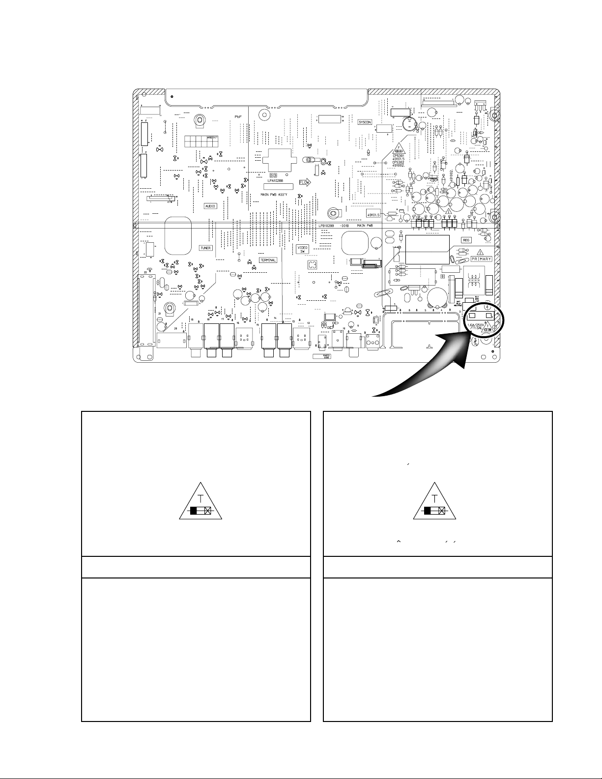
Full Fuse Replacement Marking
Graphic symbol mark
(This symbol means fast blow type fuse.)
should be read as follows ;
FUSE CAUTION
FOR CONTINUED PROTECTION AGAINST RISK
OF FIRE, REPLACE ONLY WITH SAME TYPE
AND RATING OF FUSES ;
F5001 : 1.6 A / 250 V F5001 : 1.6 A / 250 V
Marquage Pour Le Remplacement
Complet De Fusible
Le symbole graphique (Ce symbole signifie
fusible de type a fusion rapide.)
doit etre interprete comme suit ;
PRECAUTIONS SUR LES FUSIBLES
POUR UNE PROTECTION CONTINUE CONTRE
DES RISQUES D'INCENDIE, REMPLACER
SEULEMENT PAR UN FUSIBLE DU MEME TYPE ;
(No.YD058)1-5
Page 6
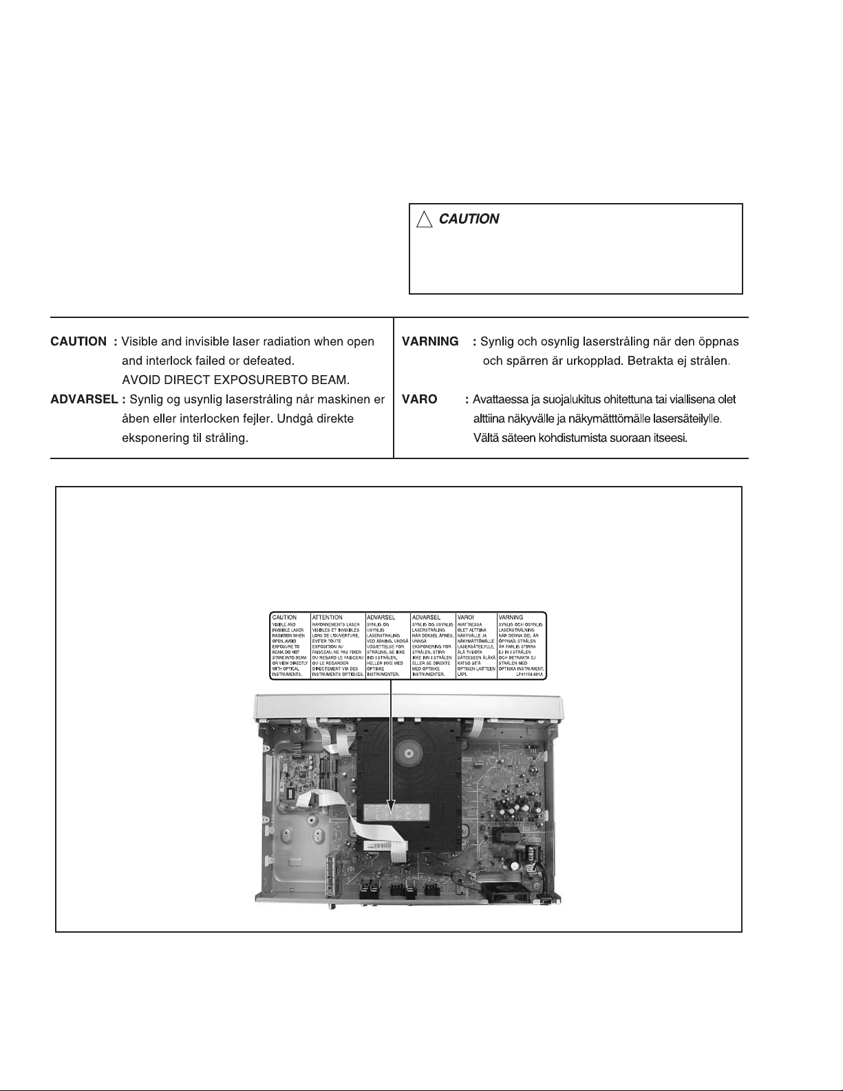
1.8 Important for laser products
!
1.CLASS 1 LASER PRODUCT
2.DANGER : Invisible laser radiation when open and inter
lock failed or defeated. Avoid direct exposure to beam.
3.CAUTION : There are no serviceable parts inside the
Laser Unit. Do not disassemble the Laser Unit. Replace
the complete Laser Unit if it malfunctions.
4.CAUTION : The CD,MD and DVD player uses invisible
laser radiation and is equipped with safety switches which
prevent emission of radiation when the drawer is open and
the safety interlocks have failed or are defeated. It is
dangerous to defeat the safety switches.
5.CAUTION : If safety switches malfunction, the laser is able
to function.
6.CAUTION : Use of controls, adjustments or performance of
procedures other than those specified here in may result in
hazardous radiation exposure.
Please use enough caution not to
see the beam directly or touch it
in case of an adjustment or operation
check.
REPRODUCTION AND POSITION OF LABEL
On mechanism assembly
1-6 (No.YD058)
Page 7

SECTION 2
SPECIFIC SERVICE INSTRUCTIONS
This service manual does not describe SPECIFIC SERVICE INSTRUCTIONS.
(No.YD058)1-7
Page 8

SECTION 3
TOP COVER
Hook b
DISASSEMBLY
3.1 Main body section
3.1.1 Remove the top cover (See figure 1)
(1) Remove the four screws A attaching the top cover on both
sides of the main body.
(2) Remove the five screws B attaching the top cover on the
back of the main body.
(3) Raise the both sides and lower part of the rear of the top
cover, with opening them slightly in an outward direction.
And the top cover will be removed.
3.1.2 Remove the front panel assembly (See figure2, figure 3)
• Prior to performing the following procedure, remove the top
cover.
• There is no need to remove the mechanism assembly.
(1) Disconnect the card wires from connectors CN7002
CN7003, CN4001 on the main board and display board.
(2) Hooks a and b are removed respectively, and the front
panel assembly is removed.
,
A x 2
TOP COVER
TOP COVER
A x 2
B
Fig.1
Front panel assembly
CN7002CN4001 CN7003
B
B
B
B
Display board
Main board
Fig.2
Hook a
Front panel assembly
Hook b
Hook a
Fig.3
1-8 (No.YD058)
Page 9

3.1.3 Remove the drive unit (See figure 4)
• Prior to performing the following procedure, remove the top
cover.
• There is no need to remove the front panel assembly.
(1) Disconnect the socket wire from connector CN5302
main board.
(2) Disconnect the card wire from connector CN2201
digital board.
(3) Remove the four screws C attaching the drive unit.
on the
on the
Digital board
CN1801
D
D
CN1101
D
C
Drive unit
C
3.1.4 Remove the digital board (See figure 4)
• Prior to performing the following procedure, remove the top
cover.
(1) Disconnect the card wire from connectors CN2201
CN1103 on the digital board.
(2) Disconnect the socket wire from connectors CN1101,
CN1102
(3) Remove the four screws D attaching the digital board.
, CN1801 on the digital board.
CN2201
D
CN1103 Main board
,
C C CN5302
CN1102
Fig.4
(No.YD058)1-9
Page 10

3.1.5 Remove the main board (See figure 5, figure 6)
• Prior to performing the following procedure, remove the top
cover, drive unit.
(1) Disconnect the card wire from connectors CN4001,
CN4103 on the main board.
(2) Disconnect the socket wire from connectors CN1101
CN1102
(3) Disconnect the socket wire from connector CN5303, on the
main board.
(4) Disconnect the power cord from connector CN5001
main board.
(5) Remove the six screws E attaching the main board.
(6) Remove the six screws F and G attaching the rear panel
with main board.
, CN7001 on the digital board and display board.
, on the
CN1101
Digital board E
,
CN4001
Display board
CN7001
E
CN5001
E
E
3.1.6 Remove the dispiay board (See figure 7)
• Prior to performing the following procedure, remove the top
cover, drive unit, front panel assembly.
(1) Disconnect the socket wire from connector CN7001
display board.
(2) Remove the two screws H attaching the display board.
on the
CN1102
CN4103
E E
Main board
Fig.5
FG
Fig.6
CN5303
Rear panel
Display board HH CN7001
Fig.7
1-10 (No.YD058)
Page 11

3.2 Loading mechanism assembly
3.2.1 Remove the clamper base (See figure 1, figure 2)
(1) The part a on the reverse side of a mechanism assembly is
made to slide in the direction of an arrow with a driver etc.
(A tray ejects a few.)
(2) Remove the two screws A attaching the clamper base.
(3) After making a clamper base slide in the direction of an ar-
row, it raises upward and removes.
(4) A tray is removed.
Par t a
Fig.1
A
A
Clamper base
Fig.2
(No.YD058)1-11
Page 12

3.2.2 Remove the traverse mechanism assembly (See figure 3, figure 4, figure 5)
• Prior to performing the following procedure, remove the
clamper base and tray.
(1) It solder to part b section on the pick-up unit.
㧯
Pick-up unit
E
D
Leaf spring
CN1
Par t b
(2) Disconnect the card wire from connector CN1
up unit.
ATTENTION:
Please extract the wire after short-circuited on the pickup unit in part b with solder. Please remove the solder of
part b after connecting the wire with CN1
bling.
(3) Disconnect the flexible wire from connector CN301
servo control board.
(4) Remove the one screw B attaching the mechanism brack-
et.
(5) Remove the four screws C and D attaching the leaf spring.
(6) Remove the two screws E and F attaching the traverse
mechanism assembly.
(7) When a traverse mechanism assembly is in the lowest po-
sition, a gear 1 is turned clockwise, and since a traverse
mechanism assembly is moved to the upper position, it is
removed.
on the pick-
when reassem-
on the
Pick-up unit
F
Traverse mechanism
Mechanism
bracket
B
assembly
Fig.3
1-12 (No.YD058)
Servo control board
Fig.4
Traverse mechanism assembly
Gear 1
Fig.5
CN301
Page 13

3.2.3 Remove the flexible wire assembly (See figure 6)
• Prior to performing the following procedure, remove the
clamper base and tray.
(1) Remove the four screws G and H attaching the flexible wire
assembly.
(2) Remove the solder part c soldered to the feed motor.
(3) Remove the two screws I attaching the shaft guide.
(4) Disconnect the flexible wire from connector CN1
spindle motor board.
on the
Par t c
G
Flexible wire
assembly
Spindle motor assembly
I
CN1
3.2.4 Remove the servo control board and board bracket (See figure 7, figure 8)
• Prior to performing the following procedure, remove the
clamper base and tray.
(1) Remove the soler part d and e soldered on the servo con-
trol board.
(2) Disconnect the flexible wire from connector CN301
servo control board.
(3) Disconnect the card wire from connector CN101
servo control board.
(4) Remove the two screws J attaching the servo control
board.
(5) Remove the four screws K attaching the board bracket.
on the
on the
K
Servo control board
CN101
J
Par t e
Fig.6
Fig.8
H
G
G
KKLBelt
Par t d
3.2.5 Remove the loading motor (See figure 7, figure 8)
• Prior to performing the following procedure, remove the
clamper base and tray.
(1) Remove the soler part d soldered on the servo control
board.
(2) A belt is removed.
(3) Remove the two screws L attaching the loading motor.
J
Fig.7
CN301
(No.YD058)1-13
Page 14

SECTION 4
ADJUSTMENT
This service manual does not describe ADJUSTMENT.
1-14 (No.YD058)
Page 15

SECTION 5
TROUBLESHOOTING
5.1 JIG Mode
The following remote control units are required to set and cancel JIG mode.
For setting : a remote control unit attached to product.
For cancellation : JIG remote control unit (part number : PTU94023B)
Remote control unit
attached to product
JIG remote control unit
JIG remote control unit
[Data transmission]
Set the data code,
and then press the
" " button.
3
Custom code
43:A Code
53:B Code
6F:C Code
7F:D Code
Data code
Initial mode
When the main body is set to JIG mode and when the main body is under JIG mode, the remote control unit attached to product operates only in "Remote Control Code 1". Since main body is in "Remote Control Code 3" when it is shipped and just after its batteries
are changed, "Remote Control Code 3" needs to be changed to "Remote Control Code 1."
< Changing Remote Control Code >
(1) Press the numeric button "1" of the remote control unit while pressing the "SET UP" button of the remote control unit. Then,
press the "ENTER" button, and then release the "SET UP" button.
(2) Press the "PLAY" button of the main body for five seconds or longer while the main body is in stand-by mode, and a current
remote control code of the main body is displayed in FL indicator of the main body.
(3) While keeping the state of (2), press the "STOP" button of the remote control unit toward the main body.
(4) The code that was set by the remote control unit blinks for 5 seconds, before the code is set to the main body.
When the FL indicator changes to "DVD1," it shows that the remote control code has been changed to "1."
"(1) a-c" shows the order of pressing the buttons.
(1)b
(1)c
(3)
(1)a
STANDBY/ON
RAM/RW
(2),(4)
DVD 1
(2)
+
CH
PUSH-OPEN
-
CH
(No.YD058)1-15
Page 16

5.1.1 Setting JIG mode
To display SYSTEM INFO or to upgrade firmware, the main body needs to be set to JIG mode.
(1) Turn the main body ON.
(2) Press the buttons of the remote control unit attached to product in the following order : "SET UP" → "2" → "8" → "ENTER"
(3) When a colon ":" between "hour" and "minute" of a clock in FL indicator blink, it means that the main body has been set to JIG
mode properly.
[ Example ]
Not in JIG mode In JIG mode
15 : 07
15 07
A colon blinks.
(4) Turn the main body OFF, and then turn it ON again.
*Once the main body is set to JIG mode, the JIG mode cannot be cancelled even if the power cord is pulled out from the wall
socket.
"(2) a-d" shows the order of pressing the buttons.
(2)b
(2)c
(3)(1),(4)
(2)d
+
CH
PUSH-OPEN
-
CH
(2)a
STANDBY/ON
RAM/RW
15:07
5.1.2 Canceling JIG mode
(1) Transmit "43-9D" to the main body by using JIG remote control unit.
(Please end a setting menu pushing “SET UP” button of the remote control unit appended to the commodity beforehand when
a setting menu is displayed.)
(2) A colon ":" between "hour" and "minute" of a clock in FL indicator light.
(3) Turn the main body OFF, and then turn it ON again.
NOTE:
After repair work, be sure to cancel JIG mode. Before returning product to a user, confirm that a colon ":" between "hour" and
"minute" of a clock in FL indicator light.
1-16 (No.YD058)
Page 17

5.2 Displaying SYSTEM INFO
In the SYSTEM INFO there is information including firmware versions of the main body and the drive unit.
(1) Set the main body to JIG mode.
(2) Transmit "43-8B" to the main body by using JIG remote control unit.
(Please end a setting menu pushing “SET UP” button of the remote control unit appended to the commodity beforehand when
a setting menu is displayed.)
(3) SYSTEM INFO menu is displayed in the television screen.
(4) To move cursor in SYSTEM INFO, use the "", "", "", and "" buttons of a remote control unit attached to product.
< VERSION >
SYSTEM INFO
VERSION INITIALIZE INFORMATION
CPRM Key Download
C-Ware / A-Ware
JVRI / Host
1394 / OSD
Analog / BE-R / FE-R
SET UP
ENTER
SELECT
SELECT WITH [CURSORS]
THEN PRESS [ENTER]
Done
PROD116 / JVC03_47
0111 / V0069
0054 / 2005M01
100 / 1 / 1
< INFORMATION >
SYSTEM INFO
VERSION INITIALIZE INFORMATION
Silicon version of E5
BSP
Drive firmware version
Drive last error
SET UP
ENTER
SELECT WITH [CURSORS]
THEN PRESS [ENTER]
SELECT
NOTE :
Items other than the ones described above are not used in service work.
1B0
1.2/101
6601
00 00 00
Version of firmware
This part is updated after the firmware of the
main body is updated.
System controller version
/ Region code (Backend) / Region code (Frontend)
Version of firmware of mechanism drive
(5) To quit the SYSTEM INFO menu, transmit "43-8B" to the main body by using JIG remote control unit.
(6) Cancel JIG mode.
(No.YD058)1-17
Page 18

5.3 Updating the firmware of the main body
• Firmware update disk supports CD-R media.
• When firmware update is necessary. information is available from the homepage of DIGITAL VIDEO STORAGE CATEGORY, CS
group.
• Please check the details of the update disc creation method by JS-NET.
(1) Set the main body to JIG mode.
(2) Transmit "43-70" to the main body by using JIG remote control unit.
(3) "UPDATE" appears in FL indicator. Load disk for update on the tray, and close the tray.
(4) Update processing is started automatically.
(5) Then, "FW UPDATE" appears in FL indicator. It takes approx. 3 minutes at maximum to update firmware.
(6) The tray is ejected. Then, take out the disk and close the tray.
(7) Turn the main body OFF, and pull out the power cord from the wall socket. Then, plug the power cord into the wall socket.
(8) "LOADING" of FL indicator disappears. Then, turn the main body ON.
(9) Display the SYSTEM INFO menu, and check the version of the firmware.
(10) Cancel JIG mode.
ATTENTION :
Firmware may sometimes not be update successfully.
If firmware is not update successfully, the tray opens, and "ERROR" appears in FL indicator.
If firmware is update successfully, the tray opens, and "OPEN" appears in FL indicator.
If the power cord is pulled out from the wall socket while "ERROR" appears, data in the flash memory is destroyed and the main
body cannot start: the flash memory needs to be replaced.
After update procedure, pay enough attention to FL indicator when the tray opens.
When "ERROR" appears, update firmware again in the following way to restore the firmware.
(1) Transmit "43-70" to the main body by using JIG remote control unit while the tray opens.
(2) When "UPDATE" appears in FL indicator, close the tray and make the main body read the disk. Update starts.
(3) The following procedures are the same as a usual update.
5.4 Updating the firmware of the drive unit
• Firmware update disc supports only DVD-RAM media.
• When firmware update is necessary, written discs are distributed by DIGITAL VIDEO STORAGE CATEGORY, CS group.
(1) Turn the main body ON.
(2) Load the update DVD-RAM disc on the tray and close the tray.
(3) “READING” is displayed in the FL indicator and the update is started.
(4) In a short while “READING” in the FL indicator disappears, open the tray to remove the disc and close the tray.
(5) Turn the power OFF and pull out the power code from the wall socket, then plug the power cord into the wall socket again.
(6) Set to the JIG mode and check the firmware version of the drive.
5.5 Setting after the drive unit replacement
When the drive unit is replaced, it is necessary to set a region code. Service drive units for replacement are not set for any region
code, and they are in an indefinite condition.
Make sure to set region code after attaching the drive unit to the main body.
Without the setting of the region code, discs that have regions cannot be played back.
(1) Replace a drive unit.
(2) Turn POWER switch of the unit ON.
(3) Set the main body to JIG mode.
(4) Insert a DVD-RAM disc in the unit to make the unit read the DVD-RAM disc.(The DVD-RAM disk used in this procedure is not a
disk for upgrade. If it is a DVD-RAM disk, it is good anything.)
(5) Send "43-F2" to the unit by using JIG remote control unit.
(6) "REGION 1" is displayed on FL display.
(7) Set the unit to STANDBY.
(8) Turn the POWER switch ON.
(9) To cancel JIG MODE, send "43-9D" to the unit by using JIG remote control unit.
(10) Colon is displayed on a clock on FL display.
(11) Setting is completed in the procedure above.
1-18 (No.YD058)
Page 19

5.6 Taking out a disc
5.6.1 Method 1
There is compulsive tray ejection mode by electric operation.
(1) AC Plug is pulled out at once and inserted again.
(2) It is displayed on FL display as "LOADING", and while it blinks, pushing the EJECT button of a main body is continued.
(3) After a while, a tray opens (About 20 seconds).
(4) A disk is removed, the tray is pushed, and a tray is made to close.
(5) The "LOADING" blink display of FL display disappears and it will be in a standby state.
(6) If the POWER button is pushed, it will usually be operating.
5.6.2 Method 2
When a disk is not able to be taken out by operation of "Method 1"
A tray can be ejected mechanically, without switching on a power supply.
(1) A drive unit is removed from a main body.
(2) The part a on the reverse side of a drive unit is made to slide in the direction of an arrow with a screw driver etc.
(3) Since a tray ejects a few, a tray is pulled out manually.
Par t a
5.7 Initialization to the factory shipment state
When the initialization is operated, internal information changes as follows. It is essential to obtain the client’s permission before the
operation.
• All DVD library is all deleted.
• All the DVD initial settings go back to the initial status.
(1) Set to the JIG mode.
(2) Transmit “43-6F” with the JIG remote control unit.
(3) FL indicator displays “FACTORY”, and changes to “CHECK OK” after blinking for a short while.
(4) Pull out the power code from the wall socket.
(5) The JIG mode is forced to cancel at the same time with the initialization, check whether the JIG mode is canceled by plugging
the power code into the wall socket again. (The colon “:” in time display should be continuously ON, not blinking.)
If the JIG mode is not canceled, transmit “43-9D” with JIG remote control unit to cancel the JIG mode.
(No.YD058)1-19
Page 20

Victor Company of Japan, Limited
AV & MULTIMEDIA COMPANY DIGITAL VIDEO STORAGE CATEGORY 12, 3-chome, Moriya-cho, kanagawa-ku, Yokohama, kanagawa-prefecture, 221-8528, Japan
(No.YD058)
Printed in Japan
VPT
 Loading...