

Page 1

Getting Started Preparation Basic Operation Settings Troubleshooting Others
LCT2488-001A
D-ILA PROJECTOR
INSTRUCTIONS
For Customer use :
Enter below the serial No. which is
located on the bottom side of the
cabinet. Retain this information for
future reference.
Model No. DLA-VS2000
Serial No.
DLA-VS2000
ENGLISH
DLA-VS2000_Cover.fm Page 1 Wednesday, August 6, 2008 12:38 PM
Page 2

1
2
Getting Started
Safety Precautions
IMPORTANT INFORMATION
About the installation place
Do not install the projector in a place that cannot support its
weight securely.
If the installation place is not sturdy enough, the projector could
fall or overturn, possibly causing personal injury.
IMPORTANT SAFEGUARDS
Electrical energy can perform many useful functions. This unit
has been engineered and manufactured to assure your personal
safety. But IMPROPER USE CAN RESULT IN POTENTIAL
ELECTRICAL SHOCK OR FIRE HAZARD. In order not to
defeat the safeguards incorporated into this product, observe the
following basic rules for its installation, use and service. Please
read these Important Safeguards carefully before use.
- All the safety and operating instructions should be read before
the product is operated.
- The safety and operating instructions should be retained for
future reference.
- All warnings on the product and in the operating instructions
should be adhered to.
- All operating instructions should be followed.
- Place the projector near a wall outlet where the plug can be
easily unplugged.
- Unplug this product from the wall outlet before cleaning. Do not
use liquid cleaners or aerosol cleaners. Use a damp cloth for
cleaning.
- Do not use attachments not recommended by the product
manufacturer as they may be hazardous.
- Do not use this product near water. Do not use immediately after
moving from a low temperature to high temperature, as this
causes condensation, which may result in fire, electric shock, or
other hazards.
- Do not place this product on an unstable cart, stand, or table.
The product may fall, causing serious injury to a child or adult,
and serious damage to the product. The product should be
mounted according to the manufacturer’s instructions, and
should use a mount recommended by the manufacturer.
- When the product is used on a cart, care
should be taken to avoid quick stops,
excessive force, and uneven surfaces which
may cause the product and cart to overturn,
damaging equipment or causing possible
injury to the operator.
- Slots and openings in the cabinet are
provided for ventilation. These ensure
reliable operation of the product and protect
it from overheating. These openings must not be blocked or
covered. (The openings should never be blocked by placing the
product on bed, sofa, rug, or similar surface. It should not be
placed in a built-in installation such as a bookcase or rack unless
proper ventilation is provided and the manufacturer’s
instructions have been adhered to.)To allow better heat
dissipation, keep a clearance between this unit and its
surrounding as shown below. When this unit is enclosed in a
space of dimensions as shown below, use an air-conditioner so
that the internal and external temperatures are the same.
This product has a High Intensity Discharge
(HID) lamp that contains mercury.
Disposal of these materials may be regulated
in your community due to environmental
considerations. For disposal or recycling
information, please contact your local
authorities or for USA, the Electronic
Industries Alliance: http://www.eiae.org.
WARNING:
TO PREVENT FIRE OR SHOCK HAZARDS, DO NOT
EXPOSE THIS APPLIANCE TO RAIN OR MOISTURE.
WARNING:
THIS APPARATUS MUST BE EARTHED.
CAUTION:
To reduce the risk of electric shock, do not remove cover.
Refer servicing to qualified service personnel.
This projector is equipped with a 3-blade grounding type
plug to satisfy FCC rule. If you are unable to insert the plug
into the outlet, contact your electrician.
FCC INFORMATION (U.S.A. only)
CAUTION:
Changes or modification not approved by JVC could void the
user’s authority to operate the equipment.
NOTE:
This equipment has been tested and found to comply with the
limits for Class B digital device, pursuant to Part 15 of the
FCC Rules. These limits are designed to provide reasonable
protection against harmful interference in a residential
installation. This equipment generates, uses, and can radiate
radio frequency energy and, if not installed and used in
accordance with the instructions, may cause harmful
interference to radio communications. However, there is no
guarantee that interference will not occur in a particular
installation. If this equipment does cause harmful
interference to radio or television reception, which can be
determined by turning the equipment off and on, the user is
encourage to try to correct the interference by one or more of
the following measures:
c Reorient or relocate the receiving antenna.
c Increase the separation between the equipment and receiver.
c Connect the equipment into an outlet on a circuit different
from that to which the receiver is connected.
c Consult the dealer or an experienced radio/TV technician for
help.
MACHINE NOISE INFORMATION (Germany only)
Changes Machine Noise Information Ordinance 3. GSGV,
January 18, 1991: The sound pressure level at the operator
position is equal or less than 25 dB (A) according to ISO
7779.
DLA-VS2000_Safety.fm Page 2 Sunday, August 24, 2008 7:38 PM
Page 3

3
ENGLISH
Getting Started Preparation Basic Operation Settings Troubleshooting Others
- This product should be operated only with the type of power
source indicated on the label. If you are not sure of the type of
power supply to your home, consult your product dealer or local
power company.
- This product is equipped with a three-wire plug. This plug will
fit only into a grounded power outlet. If you are unable to insert
the plug into the outlet, contact your electrician to install the
proper outlet. Do not defeat the safety purpose of the grounded
plug.
- Power-supply cords should be routed so that they are not likely
to be walked on or pinched by items placed upon or against
them. Pay particular attention to cords at doors, plugs,
receptacles, and the point where they exit from the product.
- For added protection of this product during a lightning storm, or
when it is left unattended and unused for long periods of time,
unplug it from the wall outlet and disconnect the cable system.
This will prevent damage to the product due to lightning and
power line surges.
- Do not overload wall outlets, extension cords, or convenience
receptacles on other equipment as this can result in a risk of fire
or electric shock.
- Never push objects of any kind into this product through
openings as they may touch dangerous voltage points or short
out parts that could result in a fire or electric shock. Never spill
liquid of any kind on the product.
- Do not attempt to service this product yourself as opening or
removing covers may expose you to dangerous voltages and
other hazards. Refer all service to qualified service personnel.
- Unplug this product from the wall outlet and refer service to
qualified service personnel under the following conditions:
a) When the power supply cord or plug is damaged.
b) If liquid has been spilled, or objects have fallen on the product.
c) If the product has been exposed to rain or water.
d) If the product does not operate normally by following the operating
instructions. Adjust only those controls that are covered by the
Operation Manual, as an improper adjustment of controls may result
in damage and will often require extensive work by a qualified
technician to restore the product to normal operation.
e) If the product has been dropped or damaged in any way.
f) When the product exhibits a distinct change in performance - this
indicates a need for service.
- When replacement parts are required, be sure the service
technician has used replacement parts specified by the
manufacturer or with same characteristics as the original part.
Unauthorized substitutions may result in fire, electric shock, or
other hazards.
- Upon completion of any service or repairs to this product, ask the
service technician to perform safety checks to determine that the
product is in proper operating condition.
- The product should be placed more than one foot away from
heat sources such as radiators, heat registers, stoves, and other
products (including amplifiers) that produce heat.
- When connecting other products such as VCR’s, and DVD
players, you should turn off the power of this product for
protection against electric shock.
- Do not place combustibles behind the cooling fan. For example,
cloth, paper, matches, aerosol cans or gas lighters that present
special hazards when over heated.
- Do not look into the projection lens while the illumination lamp
is turned on. Exposure of your eyes to the strong light can result
in impaired eyesight.
- Do not look into the inside of this unit through vents (ventilation
holes), etc. Do not look at the illumination lamp directly by
opening the cabinet while the illumination lamp is turned on.
The illumination lamp also contains ultraviolet rays and the light
is so powerful that your eyesight can be impaired.
- Do not drop, hit, or damage the light-source lamp (lamp unit) in
any way. It may cause the light-source lamp to break and lead to
injuries. Do not use a damaged light source lamp. If the lightsource lamp is broken, ask your dealer to repair it. Fragments
from a broken light-source lamp may cause injuries.
- The light-source lamp used in this projector is a high pressure
mercury lamp. Be careful when disposing of the lightsource
lamp. If anything is unclear, please consult your dealer.
- Do not ceiling-mount the projector to a place which tends to
vibrate; otherwise, the attaching fixture of the projector could be
broken by the vibration, possibly causing it to fall or overturn,
which could lead to personal injury.
- Use only the accessory cord designed for this product to prevent
shock.
150 mm and above
300 mm
and above
150 mm
and above
300 mm
and above
200 mm
and above
*DO NOT allow any unqualified person to install the unit.
Be sure to ask your dealer to install the unit (e.g. attaching it
to the ceiling) since special technical knowledge and skills
are required for installation. If installation is performed by an
unqualified person, it may cause personal injury or electrical
shock.
DLA-VS2000_Safety.fm Page 3 Sunday, August 24, 2008 7:38 PM
Page 4

4
Safety Precautions (Continued)
1
Getting Started
POWER CONNECTION
For USA and Canada only
Use only the following power cord.
Power cord
The power supply voltage rating of this product is AC110 V
– AC240 V. Use only the power cord designated by our dealer
to ensure Safety and EMC.
Ensure that the power cable used for the projector is the
correct type for the AC outlet in your country. Consult your
product dealer.
Power cord
For European Countries
WARNING:
Do not cut off the main plug from this equipment.
If the plug fitted is not suitable for the power points in your
home or the cable is too short to reach a power point, then
obtain an appropriate safety approved extension lead or
adapter or consult your dealer.
If nonetheless the mains plug is cut off, dispose of the plug
immediately, to avoid a possible shock hazard by inadvertent
connection to the main supply. If a new main plug has to be
fitted, then follow the instruction given below.
WARNING:
THIS APPARATUS MUST BE EARTHED.
IMPORTANT:
The wires in the mains lead on this product are coloured in
accordance with the following cord:
Green-and-yellow : Earth
Blue : Neutral
Brown : Live
As these colours may not correspond with the coloured
making identifying the terminals in your plug, proceed as
follows:
The wire which is coloured green-and-yellow must be
connected to the terminal which is marked M with the letter E
or the safety earth or coloured green or green-and-yellow.
The wire which is coloured blue must be connected to the
terminal which is marked with the letter N or coloured black.
The wire which is coloured brown must be connected to the
terminal which is marked with the letter L or coloured red.
If this symbol is shown, it is only valid in the
European Union.
DLA-VS2000_Safety.fm Page 4 Sunday, August 24, 2008 7:38 PM
Page 5

5
ENGLISH
Getting Started Preparation Basic Operation Settings Troubleshooting Others
DLA-VS2000_Safety.fm Page 5 Sunday, August 24, 2008 7:38 PM
Page 6

1
6
Getting Started
ENGLISH
Information for Users on Disposal of Old Equipment
[European Union]
This symbol indicates that the electrical and electronic equipment
should not be disposed as general household waste at its end-of-life.
Instead, the product should be handed over to the applicable collection
point for the recycling of electrical and electronic equipment for proper
treatment, recovery and recycling in accordance with your national
legislation.
By disposing of this product correctly, you will help to conserve natural
resources and will help prevent potential negative effects on the
environment and human health which could otherwise be caused by
inappropriate waste handling of this product. For more information
about collection point and recycling of this product, please contact your
local municipal office, your household waste disposal service or the
shop where you purchased the product.
Penalties may be applicable for incorrect disposal of this waste, in
accordance with national legislation.
(Business users)
If you wish to dispose of this product, please visit our web page
www.jvc-europe.com
to obtain information about the take-back of the
product.
[Other Countries outside the European Union]
If you wish to dispose of this product, please do so in accordance with
applicable national legislation or other rules in your country for the
treatment of old electrical and electronic equipment.
DEUTSCH
Benutzerinformationen zur Entsorgung alter Geräte
[Europäische Union]
Dieses Symbol zeigt an, dass das elektrische bzw. elektronische Gerät nicht
als normaler Haushaltsabfall entsorgt werden soll. Stattdessen sollte das
Produkt zur fachgerechten Entsorgung, Weiterverwendung und
Wiederverwertung in Übereinstimmung mit der Landesgesetzgebung einer
entsprechenden Sammelstelle für das Recycling elektrischer und
elektronischer Geräte zugeführt werden.
Die korrekte Entsorgung dieses Produkts dient dem Umweltschutz und
verhindert mögliche Schäden für die Umwelt und die menschliche
Gesundheit, welche durch unsachgemäße Behandlung des Produkts auftreten
können. Weitere Informationen zu Sammelstellen und dem Recycling dieses
Produkts erhalten Sie bei Ihrer Gemeindeverwaltung, Ihrem örtlichen
Entsorgungsunternehmen oder in dem Geschäft, in dem Sie das Produkt
gekauft haben.
Für die nicht fachgerechte Entsorgung dieses Abfalls können gemäß der
Landesgesetzgebung Strafen ausgesprochen werden.
(Geschäftskunden)
Wenn Sie dieses Produkt entsorgen möchten, besuchen Sie bitte unsere
Webseite www.jvc-europe.com
, um Informationen zur Rücknahme des
Produkts zu erhalten.
[Andere Länder außerhalb der Europäischen Union]
Wenn Sie dieses Produkt entsorgen möchten, halten Sie sich dabei bitte an die
entsprechenden Landesgesetze und andere Regelungen in Ihrem Land zur
Behandlung elektrischer und elektronischer Geräte.
Attention:
This symbol is only
valid in the European
Union.
Hinweis:
Dieses Symbol ist nur
in der Europäischen
Uniongültig.
FRANÇAIS
Informations relatives à l’élimination des appareils
usagés, à l’intention des utilisateurs
[Union européenne]
Lorsque ce symbole figure sur un appareil électrique et électronique, cela
signifie qu’il ne doit pas être éliminé en tant que déchet ménager à la fin
de son cycle de vie. Le produit doit être porté au point de pré-collecte
approprié au recyclage des appareils électriques et électroniques pour y
subir un traitement, une récupération et un recyclage, conformément à la
législation nationale.
En éliminant correctement ce produit, vous contriburez à la conservation
des ressources naturelles et à la prévention des éventuels effets négatifs
sur l’environnement et la santé humaine, pouvant être dus à la
manipulation inappropriée des déchets de ce produit. Pour plus
d’informations sur le point de pré-collecte et le recyclage de ce produit,
contactez votre mairie, le service d’évacuation des ordures ménagères ou
le magasin dans lequel vous avez acheté le produit.
Des amendes peuvent être infligées en cas d’élimination incorrecte de ce
produit, conformément à la législation nationale.
(Utilisateurs professionnels)
Si vous souhaitez éliminer ce produit, visitez notre page Web www.jvceurope.com afin d’obtenir des informations sur sa récupération.
[Pays ne faisant pas partie de l’Union européenne]
Si vous souhaitez éliminer ce produit, faites-le conformément à la
législation nationale ou autres règles en vigueur dans votre pays pour le
traitement des appareils électriques et électroniques usagés.
NEDERLANDS
Informatie voor gebruikers over het weggooien van
oude apparatuur
[Europese Unie]
Deze markering geeft aan dat de elektrische en elektronische apparatuur
bij het einde van de gebruiksduur niet bij het huishoudelijk afval mag
worden gegooid. Het product moet in plaats daarvan worden ingeleverd
bij het relevante inzamelingspunt voor hergebruik van elektrische en
elektronische apparatuur, voor juiste verwerking, terugwinning en
hergebruik in overeenstemming met uw nationale wetgeving.
Door dit product naar het inzamelingspunt te brengen, werkt u mee aan
het behoud van natuurlijke hulpbronnen en met het voorkomen van
potentiële negatieve effecten op het milieu en de volksgezondheid, die
anders veroorzaakt zouden kunnen worden door onjuiste
afvalverwerking van dit product. Neem voor meer informatie over
inzamelingspunten en hergebruik van dit product contact op met de
gemeente in uw woonplaats, het afvalverwerkingsbedrijf of de winkel
waar u het product hebt aangeschaft.
Er kunnen boetes gelden voor een onjuiste verwijdering van dit afval, in
overeenstemming met de nationale wetgeving.
(Zakelijke gebruikers)
Bezoek als u dit product wilt weggooien onze website
www.jvc-
europe.com
voor informatie over het terugnemen van het product.
[Landen buiten de Europese Unie]
Wanneer u dit product wilt verwijderen, houdt u dan aan de geldende
nationale wetgeving of andere regels in uw land voor de verwerking
van oude elektrische en elektronische apparatuur.
Attention:
Ce symbole n’est
reconnu que dans
l’Union européenne.
Let op:
Dit symbool is alleen
geldig in de Europese
Unie.
DLA-VS2000_Safety.fm Page 6 Sunday, August 24, 2008 7:38 PM
Page 7

7
ENGLISH
Getting Started Preparation Basic Operation Settings Troubleshooting Others
ESPAÑOL / CASTELLANO
Información para los usuarios sobre la eliminación de
equipos usados
[Unión Europea]
Este símbolo indica que los aparatos eléctricos y electrónicos no deben
desecharse junto con la basura doméstica al final de su vida útil. El
producto deberá llevarse al punto de recogida correspondiente para el
reciclaje y el tratamiento adecuado de equipos eléctricos y electrónicos de
conformidad con la legislación nacional.
Si desecha el producto correctamente, estará contribuyendo a conservar
los recursos naturales y a prevenir los posibles efectos negativos en el
medio ambiente y en la salud de las personas que podría causar el
tratamiento inadecuado del producto desechado. Para obtener más
información sobre el punto de recogida y el reciclaje de este producto,
póngase en contacto con su oficina municipal, su servicio de recogida
de basura doméstica o la tienda en la que haya adquirido el producto.
De acuerdo con la legislación nacional, podrían aplicarse multas por la
eliminación incorrecta de estos desechos.
(Empresas)
Si desea desechar este producto, visite nuestra página Web www.jvceurope.com para obtener información acerca de la retirada del producto.
[Otros países no pertenecientes a la Unión Europea]
Si desea desechar este producto, hágalo de conformidad con la
legislación nacional vigente u otras normativas de su país para el
tratamiento de equipos eléctricos y electrónicos usados.
ITALIANO
Informazioni per gli utenti sullo smaltimento delle
apparecchiature obsolete
[Unione Europea]
Questo simbolo indica che l’apparecchiatura elettrica ed elettronica a cui è
relativo non deve essere smaltita tra i rifiuti domestici generici alla fine
della sua vita utile. Il prodotto, invece, va consegnato a un punto di raccolta
appropriato per il riciclaggio di apparecchiature elettriche ed elettroniche,
per il trattamento, il recupero e il riciclaggio corretti, in conformità alle
proprie normative nazionali.
Mediante lo smaltimento corretto di questo prodotto, si contribuirà a
preservare le risorse naturali e a prevenire potenziali effetti negativi
sull’ambiente e sulla salute umana che potrebbero essere provocati,
altrimenti, da uno smaltimento inappropriato del prodotto. Per ulteriori
informazioni sul punto di raccolta e il riciclaggio di questo prodotto,
contattare la sede comunale locale, il servizio di smaltimento rifiuti
domestici o il negozio in cui si è acquistato il prodotto.
L’utente è responsabile del conferimento dell’apparecchio a fina vita
alle appropriate strutture di raccolta, pena le sanzioni previste dalla
vigente legislazione sui rifiuti.
(Per gli utenti aziendali)
Qualora si desideri smaltire questo prodotto, visitare la nostra pagina
web www.jvc-europe.com
per ottenere informazioni sul ritiro del
prodotto.
[Per altre nazioni al di fuori dell’Unione Europea]
Qualora si desideri smaltire questo prodotto, effettuare lo smaltimento
in conformità alla normativa nazionale applicabile o alle altre leggi
della propria nazione relative al trattamento delle apparecchiature
elettriche ed elettroniche obsolete.
Atención:
Este símbolo sólo es
válido en la Unión
Europea.
Attenzione:
Questo simbolo è valido
solo nell’Unione Europea.
PORTUGUÊS
Informações para os Utilizadores sobre a Eliminação
de Equipamento Antigo
[União Europeia]
Este símbolo indica que o equipamento eléctrico e electrónico não deve
ser eliminado como um resíduo doméstico geral, no fim da respectiva
vida útil. Pelo contrário, o produto deve ser entregue num ponto de
recolha apropriado, para efectuar a reciclagem de equipamento
eléctrico e electrónico e aplicar o tratamento, recuperação e reciclagem
adequados, de acordo com a respectiva legislação nacional.
Ao eliminar este produto da forma correcta, ajudará a conservar
recursos naturais e ajudará a evitar potenciais efeitos negativos no
ambiente e saúde humana, que poderiam ser causados pelo tratamento
residual inadequado deste produto. Para mais informações sobre o
ponto de recolha e reciclagem deste produto, contacte a respectiva
entidade local, o serviço de eliminação de resíduos ou a loja onde
adquiriu o produto.
Caso estes resíduos não sejam correctamente eliminados, poderão ser
aplicadas penalizações, em conformidade com a respectiva legislação
nacional.
(utilizadores profissionais)
Se pretender eliminar este produto, visite a nossa página da web em
www.jvc-europe.com
para obter informações sobre a devolução do
produto.
[Outros países fora da União Europeia]
Se pretender eliminar este produto, faça-o de acordo com a legislação
nacional aplicável ou outras regras no seu país para o tratamento de
equipamento eléctrico e electrónico velho.
ΕΛΛΗΝΙΚΑ
Πληροφορίες σχετικά µε την απόρριψη
εξοπλισµού
[Ευρωπαϊκή Ένωση]
Αυτή η σήµανση υποδηλώνει ότι ο ηλεκτρικός και ηλεκτρονικός
εξοπλισµός δεν πρέπει να απορριφθεί ως κοινό οικιακό
απόρριµµα. Αντ' αυτού, το προϊόν πρέπει να παραδοθεί στο
ανάλογο σηµείο περισυλλογής για την ανακύκλωση των
ηλεκτρικών και ηλεκτρονικών µερών και την κατάλληλη
επεξεργασία, σύµφωνα µε τη νοµοθεσία
της χώρας σας.
Η σωστή απόρριψη αυτού το προϊόντος βοηθάει στη διαφύλαξη
των φυσικών πόρων και στην αποφυγή αρνητικών επιπτώσεων
στο περιβάλλον και στην ανθρώπινη υγεία, κάτι που ενδέχεται να
προκληθεί από την ακατάλληλη διαχείριση αυτού του προϊόντος
ως απόρριµµα. Για περισσότερες πληροφορίες σχετικά µε τα
σηµεία περισυλλογής
και ανακύκλωσης αυτού του προϊόντος,
επικοινωνήστε µε τα γραφεία της τοπικής αυτοδιοίκησης, την
υπηρεσία περισυλλογής απορριµµάτων ή το κατάστηµα από το
οποίο αγοράσατε το προϊόν.
Ανάλογα µε τη νοµοθεσία της χώρας σας, ενδέχεται να
επιβληθούν κυρώσεις σε περίπτωση λανθασµένης απόρριψης
αυτού του προϊόντος.
(Επιχειρήσεις)
Αν επιθυµείτε να απορρίψετε αυτό το προϊόν, επισκεφτείτε το
διαδικτυακό µας τόπο www.jvc-europe.com
για περισσότερες
πληροφορίες σχετικά µε την επιστροφή του προϊόντος.
[Άλλες χώρες εκτός Ευρωπαϊκής Ένωσης]
Αν επιθυµείτε να απορρίψετε αυτό το προϊόν, πρέπει να
τηρήσετε την ισχύουσα εθνική νοµοθεσία ή όποιους άλλους
κανονισµούς για τη χώρα σας για την απόρριψη ηλεκτρικού και
ηλεκτρονικού εξοπλισµού.
Atenção:
Este símbolo apenas é
válido na União Europeia.
Προσοχή:
Αυτή η σήµανση ισχύει
µόνο για την
Ευρωπαϊκή Ένωση.
DLA-VS2000_Safety.fm Page 7 Sunday, August 24, 2008 7:38 PM
Page 8

1
8
Getting Started
DANSK
Brugerinformation om bortskaffelse af gammelt
udstyr
[EU]
Elektriske produkter og elektroniske apparater med dette symbol må
ikke afhændes på samme måde som almindeligt husholdningsaffald, når
det skal smides ud. I stedet skal produktet indleveres på det relevante
indsamlingssted for elektriske apparater og elektronisk udstyr, hvor det
vil blive håndteret korrekt og efterfølgende genanvendt og recirkuleret i
henhold til de love, der gælder i dit land.
Ved at bortskaffe dette produkt korrekt, medvirker du til at bevare
naturens ressourcer samt forhindre eventuelle negative påvirkninger af
miljøet og folkesundheden, der ellers kunne forårsages ved forkert
affaldshåndtering af dette produkt. Mere information om
indsamlingssteder og genanvendelse af dette produkt kan du få ved at
kontakte din lokale kommune, dit renovationsselskab eller den
forretning, hvor du har købt produktet.
Ukorrekt bortskaffelse af dette affald kan være strafbar ifølge
lovgivningen i nogle lande.
(Professionelle brugere)
Hvis du ønsker at bortskaffe dette produkt, kan du på vores webside
www.jvc-europe.com
få information om tilbagetagning af produktet.
[Lande uden for EU]
Hvis du ønsker at bortskaffe dette produkt, bedes du gøre det i
overensstemmelse med gældende lovgivning eller andre regler i dit land
for behandling af gammelt elektrisk og elektronisk udstyr.
SUOMI
Tietoja käyttäjille vanhojen laitteiden hävittämisestä
[Euroopan unioni]
Tämä symboli tarkoittaa, että sähkö- ja elektroniikkalaitteita ei tule
laittaa talousjätteisiin, kun ne poistetaan käytöstä. Sen sijaan tuotteet
tulee toimittaa asianmukaiseen sähkö- ja elektroniikkalaitteiden
kierrätyspisteeseen, jossa ne käsitellään uusiokäyttöä ja kierrätystä
varten paikallisen lainsäädännön mukaan.
Kun hävität tuotteen asianmukaisella tavalla, autat säästämään
luonnonvaroja ja estämään mahdollisia ympäristö- ja terveyshaittoja,
joita voisi aiheutua tämän tuotteen vääränlaisesta hävittämisestä.
Lisätietoja keräyspisteistä ja tämän tuotteen kierrätyksestä saat
paikkakuntasi viranomaisilta, kotitalousjätteiden keräyksestä
huolehtivasta yrityksestä tai liikkeestä, josta ostit tuotteen.
Tuotteen vääränlaisesta hävittämisestä voi seurata paikallisen
lainsäädännön mukaisia rangaistuksia.
(Yrityskäyttäjät)
Jos haluat hävittää tämän tuotteen, web-sivustoltamme osoitteessa
www.jvc-europe.com
löydät tietoja käytetyn tuotteen palautuksesta.
[Muut maat Euroopan unionin ulkopuolella]
Jos haluat hävittää tämän tuotteen, tee se kansallisen lainsäädännön tai
muiden maassasi voimassa olevien määräysten mukaan, jotka koskevat
vanhojen sähkö- ja elektroniikkalaitteiden käsittelyä.
Bemærk:
Dette symbol er kun
gyldigt i EU.
Huomio:
Tämä symboli on
voimassa vain Euroopan
unionissa.
SVENSKA
Information till användare gällande kassering av
gammal utrustning
[Europeiska gemenskapen]
Denna symbol anger att elektrisk och elektronisk utrustning inte ska
kasseras som vanligt hushållsavfall, när de inte ska användas mer.
Istället ska produkten lämnas in på lämplig återvinningsstation för
elektrisk eller elektronisk utrustning, så att den kan tas om hand och
återvinnas i enlighet med ert lands lagstiftning.
Genom att avyttra denna profukt på rätt sätt, bidrar du till att bevara
naturen och förhindrar potentiellt negativa effekter på miljön och den
mänskiliga hälsan, som annars kan bli resultatet vid felaktig hantering
av denna produkt. Kontakta ditt kommunkontor, det företag som
hanterar dina hushållssopor eller butiken där du köpt produkten, för mer
information om återvinningscentraler.
Det kan hända att du bötfälls i enlighet med ert lands lagstiftning om
detta avfall kasseras på fel sätt.
(Företagsanvändare)
Om ni vill kassera denna produkt, besök vår webbsida www.jvceurope.com för att få information om returnering av produkten.
[Övriga länder utanför den Europeiska
gemenskapen]
Om du vill kassera denna produkt, ska detta göras i enlighet med
gällande lagstiftning i landet, eller enligt andra bestämmelser i ditt land,
för behandling av gammal elektrisk eller elektronisk utrustning.
NORSK
Informasjon til brukerne om kassering av gammelt
utstyr
[Europeiske Union]
Dette symbolet betyr at det elektriske eller elektroniske utstyret ikke
skal kasseres som vanlig husholdningsavfall når det har nådd slutten av
sin levetid. I stedet skal produktet leveres til en passende
mottaksstasjon for kasserte elektriske og elektroniske produkter, slik at
disse kan behandles, gjenvinnes og resirkuleres i samsvar med nasjonal
lovgivning.
Hvis du kasserer dette produktet på riktig måte, bidrar til du til å bevare
naturlige ressurser og til å motvirke de negative virkningene på miljøet
og den menneskelige helse som kan oppstå hvis produktet kasseres på
feil måte. Hvis du vil ha mer informasjon om mottaksstasjoner og
gjennvinning av dette produktet, kan du ta kontakt med kommunen din,
renovasjosselskapet ditt eller den forhandleren du kjøpte produktet av.
Feilaktig kassering av dette utstyret kan kanskje bøtelegges, avhengig
av nasjonale lover og regler.
(Bedriftsbrukere)
Hvis du ønsker å kassere dette produktet, kan du gå til hjemmesiden vår
på www.jvc-europe.com
eller www.elretur.no for å få informasjon om
retur av dette produktet.
[Andre land utenfor EU]
Hvis du ønsker å kassere dette produktet, må du gjøre det i samsvar
med gjeldende nasjonal lovgivning eller andre regler som gjelder i
landet ditt når det gjelder behandling av gammelt elektrisk og
elektronisk utstyr.
Tänk på:
Att denna symbol endast
gäller inom den
Europeiska gemenskapen.
OBS!
Dette symbolet er kun
gyldig i den Europeiske
Union og i EFTA-landene
Norge, Island og Sveits.
DLA-VS2000_Safety.fm Page 8 Sunday, August 24, 2008 7:38 PM
Page 9

5
ENGLISH
Getting Started Preparation Basic Operation Settings Troubleshooting Others
DLA-RS1X_EN.book Page 5 Thursday, February 21, 2008 6:13 PM
Page 10

8
1
Getting Started
..................................................
.
Getting Started
Safety Precautions................................................2
Main Features .....................................................6
Contents..............................................................8
How to Read this Manual/
Accessories/Optional Accessories.......................9
About this Manual...........................................................9
Check the Accessories......................................................9
Optional Accessories.......................................................9
Controls and Features ........................................10
How to Use the Remote Control...........................13
Loading Batteries...........................................................13
Effective Range of Remote Control Unit............................13
..................................................
.
Preparation
Selecting Connecting Devices..............................14
Connecting........................................................15
Connecting via Video Cable...........................................15
Connecting via S-video Cable ........................................15
Connecting via HDMI Cable Or
HDMI-DVI Conversion Cable........................................16
Connecting via Component Video Cable .........................16
Connecting via SCART-RCA Cable..................................17
Connecting via RGB Video Cable ...................................17
Installing the Projector and Screen.......................18
Screen Size and Projection Distance................................19
..................................................
.
Basic Operation
Projecting Image................................................20
Convenient Features during Projection.................22
Setting the Screen Size...................................................22
Masking the Surrounding Area of an Image ....................22
..................................................
.
Settings
Setting Menu .....................................................24
Procedures for Menu Operation .....................................24
Setting Menu.................................................................25
Customizing Projected Images ............................32
Changing the Default Image Profile Values......................32
Registering User-defined Image Profiles...........................33
..................................................
.
Troubleshooting
Troubleshooting.................................................34
What to Do When These Messages
Are Displayed .................................................36
About Warning Indicators..................................37
Actions to Be Taken for Warning Mode .......................... 37
Replacing the Lamp ...........................................38
Procedure for Lamp Replacement ................................... 38
Resetting Lamp Time...................................................... 40
Cleaning and Replacing the Filter........................41
..................................................
.
Others
RS-232C Interface .............................................42
RS-232C Specifications ................................................. 42
Command Format .........................................................42
RS-232C Communication Examples................................ 46
Copyright and Caution.......................................47
About Trademarks and Copyright .................................. 47
Caution........................................................................47
Mounting this Unit......................................................... 48
Specifications ....................................................49
Dimensions................................................................... 50
Contents
DLA-RS1X_EN.book Page 8 Thursday, February 21, 2008 6:13 PM
Page 11

9
Getting Started Preparation Basic Operation Settings Troubleshooting Others
ENGLISH
How to Read this Manual/
Accessories/Optional Accessories
z Instruction manual, warranty card and other printed material are also included.
Please check with your authorized dealer for details.
z
Replacement Lamp: BHL5009-S (Lamp Unit)
z Replacement Filter: LC32058-002A (Inner Filter)
About this Manual
This manual mainly describes the operating method using the remote
control.
z
Buttons on the remote control are described as [Button Name].
z Selection items on the menu are described as “Selection Item”.
Conventions in this manual
Describes the limitations of the functions or usage.
Indicates good-to-know information.
Describes operational precautions.
pP9
Indicates related pages.
Buttons to be used are colored in a
darker shade.
Check the Accessories
Optional Accessories
LIGHTTEST
EXIT
SHARP
-
SHARP
+
USER
2
N
COLOR
TEMP
GAMMA
USER
3
D
COLOR
-
COLOR
+
USER
1
C
CONTRAST
BRIGHT
HIDE
INFO
MENU
ENTER
O
PE
R
AT
E
L
IG
H
T
T
E
S
T
E
X
IT
SH
AR
P
-
S
H
A
R
P
+
US
E
R
2
S
-
V
I
D
E
O
V
I
D
E
O
A
S
P
E
C
T
H
D
M
I
2
O
F
F
.
.
.
.
..
.
.
.
.
.
.
..
.
.
H
D
M
I
1
C
O
M
P
N
N
AT
U
R
AL
C
I
N
EMA
DY
N
A
MI
C
CO
L
O
R
T
E
M
P
G
A
M
M
A
US
E
R
3
D
CO
L
O
R
-
CO
L
O
R
+
US
E
R
1
C
CO
N
T
R
A
S
T
B
R
I
G
H
T
H
I
D
E
I
N
F
O
M
E
N
U
E
N
T
E
R
O
N
Remote Control
AAA size Batteries
(for operation confirmation)
Power Cord
(2.4 m)
DLA-RS1X_EN.book Page 9 Thursday, February 21, 2008 6:13 PM
Page 12

1
10
Getting Started
Controls and Features
Rear Side/Top Surface
Exhaust Vent
Lamp Cover (pP38)
To connect the power cord (pP20)
Remote Sensor (pP13)
Front Side/Left Side
Remote Sensor
(pP13)
Air Inlets
Lens Cap
z This unit comes with buffer material that cushions the lens. Remove the buffer
material before use.
z Do not throw away the buffer material, retain for future use. (pP47)
To adjust the size of the image
(pP21)
To adjust the focus
(pP21)
DLA-RS1X_EN.book Page 10 Thursday, February 21, 2008 6:13 PM
Page 13

11
Getting Started Preparation Basic Operation Settings Troubleshooting Others
ENGLISH
WARNING
LAMP
STANDBY/ON
HIDE
INPUT
STANDBY/ON
MENU
ENTER
EXIT
Light on (Red):
Warning mode (pP37)
Light on/Blinking (Orange):
Lamp warning (pP37)
To turn on/off the power
To hide the image temporarily (pP21)
To return to the previous menu
To switch input
(pP20)
To display the menu
(pP24)
Light on (Red):
Standby mode
Light on (Green):
During projection
Blinking (Green):
Image is temporarily hidden
(pP21)
Blinking (Red):
Cool Down mode (pP21)
To select or confirm
Air Inlets/Filter (pP41)
To adjust the position of the image (pP19)
Feet: The height (0 to 5 mm) can be adjusted by turning the foot.
Bottom Surface
DLA-RS1X_EN.book Page 11 Thursday, February 21, 2008 6:13 PM
Page 14
12
Controls and Features (Continued)
1
Getting Started
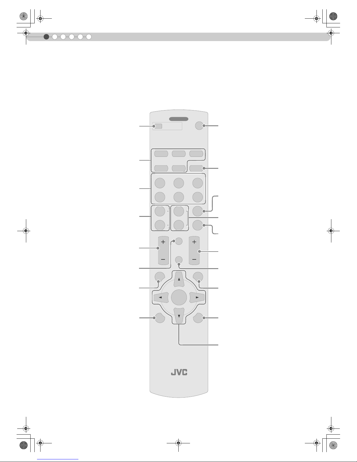
Remote Control
PROJECTOR
OPERATE
LIGHTTEST
EXIT
SHARP
-
SHARP
+
USER
2
S-VIDEOVIDEO ASPECT
HDMI 2
OFF
........ ........
HDMI 1 COMP.
N
NATURALCINEMA DYNAMIC
COLOR
TEMP
GAMMA
USER
3
D
COLOR
-
COLOR
+
USER
1
C
CONTRAST
BRIGHT
HIDE
INFO
MENU
ENTER
ON
To turn on the power
To set the screen size
(pP22)
To set gamma
(pP32)
To adjust the outline of the image
(pP32)
To set color temperature
(pP32)
To hide the image temporarily
(pP21)
To adjust brightness
(pP32)
To return to the previous menu
To illuminate buttons on the remote control
To select or confirm
Select input mode (pP20)
To turn off the power
To adjust color density
(pP32)
To switch image profile
(pP32)
To adjust contrast
(pP32)
To display information
To display the menu
(pP24)
To display test patterns
DLA-RS1X_EN.book Page 12 Thursday, February 21, 2008 6:13 PM
Page 15

13
Getting Started Preparation Basic Operation Settings Troubleshooting Others
ENGLISH
How to Use the Remote Control
z If the remote control has to be brought closer to the projector to operate, it means that the batteries are wearing out. When this
happens, replace the batteries. Insert the batteries according to the +- marks.
z Be sure to insert the - end first.
z If an error occurs when using the remote control, remove the batteries and wait for 5 minutes. Load the batteries again and
operate the remote control.
Loading Batteries
Effective Range of Remote Control Unit
When directing the remote control
toward this unit
z
When aiming the remote control towards the
remote sensor on this unit, ensure that the
distance to the sensor in front or at the rear of
this unit is within 7 m.
z If the remote control fails to work properly,
move closer to this unit.
When reflecting off a screen
z
Ensure that total of distance A between this
unit and screen and distance B between
remote control and screen is within 7 m.
z As the efficiency of signals reflected from the
remote control unit differ with the type of
screen used, operable distance may
decrease.
12 3
O
P
E
R
A
T
E
L
I
G
H
T
T
E
S
T
E
X
I
T
S
H
A
R
P
-
S
H
A
R
P
+
U
S
E
R
2
S
-
V
I
D
E
O
V
I
D
E
O
A
S
P
E
C
T
H
D
M
I
2
O
F
F
..
...
..
.
..
.....
.
H
D
MI
1
C
O
MP
N
N
A
T
U
R
A
L
C
I
N
E
M
A
D
Y
N
A
M
I
C
C
O
L
O
R
T
E
M
P
G
A
M
M
A
U
S
E
R
3
D
C
O
L
O
R
-
C
O
L
O
R
+
U
S
E
R
1
C
C
ON
T
R
A
S
T
B
R
I
G
H
T
H
I
D
E
I
N
F
O
M
E
N
U
E
NT
E
R
O
N
30°
20°
20°
30°
30°
20°
20°
30°
30°
20°
20°
30°
30°
Remote Control
This unit
O
P
E
RA
T
E
L
I
G
H
T
T
E
S
T
E
X
I
T
S
H
A
R
P
-
S
H
A
R
P
+
U
S
E
R
2
S-
V
I
D
EO
V
I
D
EO
ASPE
C
T
H
D
M
I
2
O
F
F
.
..
..
..
..
..
.
.
...
H
D
M
I
1
C
O
M
P
N
N
A
T
U
R
A
L
C
INE
M
A
D
Y
N
A
M
I
C
C
O
L
O
R
T
E
M
P
G
A
M
M
A
U
S
E
R
3
D
C
O
L
O
R
-
C
O
L
O
R
+
U
S
E
R
1
C
C
O
N
T
R
A
S
T
B
R
I
G
H
T
H
I
D
E
I
N
F
O
M
E
N
U
E
NT
E
R
ON
20°
20°
30°
30°
A
B
20°
20°
30°
30°
A
B
This unit
Remote Control
Screen
DLA-RS1X_EN.book Page 13 Thursday, February 21, 2008 6:13 PM
Page 16
2
Preparation
18
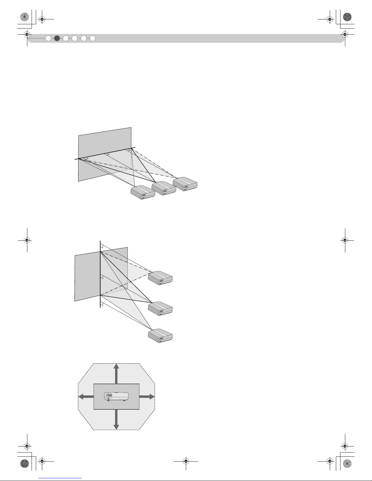
Installing the Projector and Screen
Install this unit and the screen. Place this unit and the screen perpendicular to each other.
Failing to do so may give rise to trapezoidal distortion of the projected image.
A Install the projector and screen
80%
34% 34%
80%
S-VIDEO
MDMI2 MDMI1 RS-232C
COMPONENT
VIDEO
SYNC
Y CB/PBCR/P
R
GBR
Left/Right position
*0 % up/down position (center)
Up/Down position
*0 % left/right position (center)
Approximately 34 % (maximum) of the projected image
(Turn the dial to the left for maximum)
Approximately 34 % (maximum) of the projected image
(Turn the dial to the right for maximum)
Approximately 80 % (maximum) of the projected image
(Turn the dial to the left for maximum)
Approximately 80 % (maximum) of the projected image
(Turn the dial to the right for maximum)
Shifting range of projected image
DLA-RS1X_EN.book Page 18 Thursday, February 21, 2008 6:13 PM
Page 17
19
ENGLISH
Getting Started Preparation Basic Operation Settings Troubleshooting Others
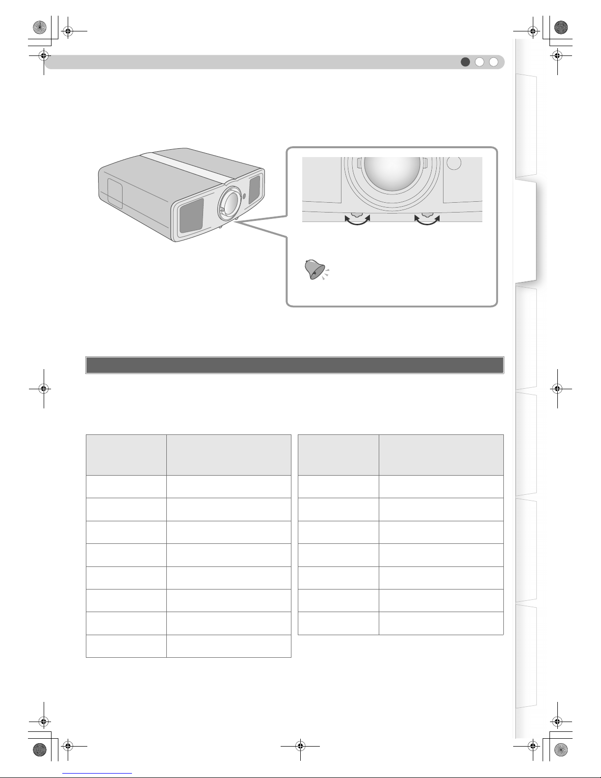
B Adjust such that the projected image is in the center of the screen
z It may be necessary to set “Pixel Adjust” in the setting menu after adjusting the image position. (pP27 - J)
Determine the distance from the lens to the screen to achieve your desired screen size.
This unit uses a 2.0x manual zoom lens for projection.
Relationship Between Projection Screen Size and Projection Distance
z
The projection distances in the table are provided only as a guide. Use them as a reference during installation.
z To adjust the installation, use a projected image of aspect ratio 16:9.
Screen Size and Projection Distance
Projection Screen
Size
(Diagonal Length)
Aspect Ratio 16:9
Approximate Projection Distance
W (Wide) to T (Tele)
Projection Screen
Size
(Diagonal Length)
Aspect Ratio 16:9
Approximate Projection Distance
W (Wide) to T (Tele)
60"
(Approx. 1.52 m)
Approx.
1.78 m
to
Approx.
3.63 m
140"
(Approx. 3.56 m)
Approx.
4.24 m
to
Approx.
8.54 m
70"
(Approx. 1.78 m)
Approx.
2.09 m
to
Approx.
4.24 m
150"
(Approx. 3.81 m)
Approx.
4.55 m
to
Approx.
9.16 m
80"
(Approx. 2.03 m)
Approx.
2.40 m
to
Approx.
4.86 m
160"
(Approx. 4.06 m)
Approx.
4.86 m
to
Approx.
9.77 m
90"
(Approx. 2.29 m)
Approx.
2.71 m
to
Approx.
5.47 m
170"
(Approx. 4.32 m)
Approx.
5.16 m
to
Approx.
10.38 m
100"
(Approx. 2.54 m)
Approx.
3.01 m
to
Approx.
6.08 m
180"
(Approx. 4.57 m)
Approx.
5.47 m
to
Approx.
11.00 m
110"
(Approx. 2.79 m)
Approx.
3.32 m
to
Approx.
6.70 m
190"
(Approx. 4.83 m)
Approx.
5.78 m
to
Approx.
11.61 m
120"
(Approx.3.05 m)
Approx.
3.63 m
to
Approx.
7.31 m
200"
(Approx. 5.08 m)
Approx.
6.08 m
to
Approx.
12.23 m
130"
(Approx. 3.30 m)
Approx.
3.93 m
to
Approx.
7.93 m
Moves the image up or
down
Moves the image to the
left or right
z Adjustment can be done easily by moving the image
upwards towards the center.
TIPS
DLA-RS1X_EN.book Page 19 Thursday, February 21, 2008 6:13 PM
Page 18
20
3
Basic Operation
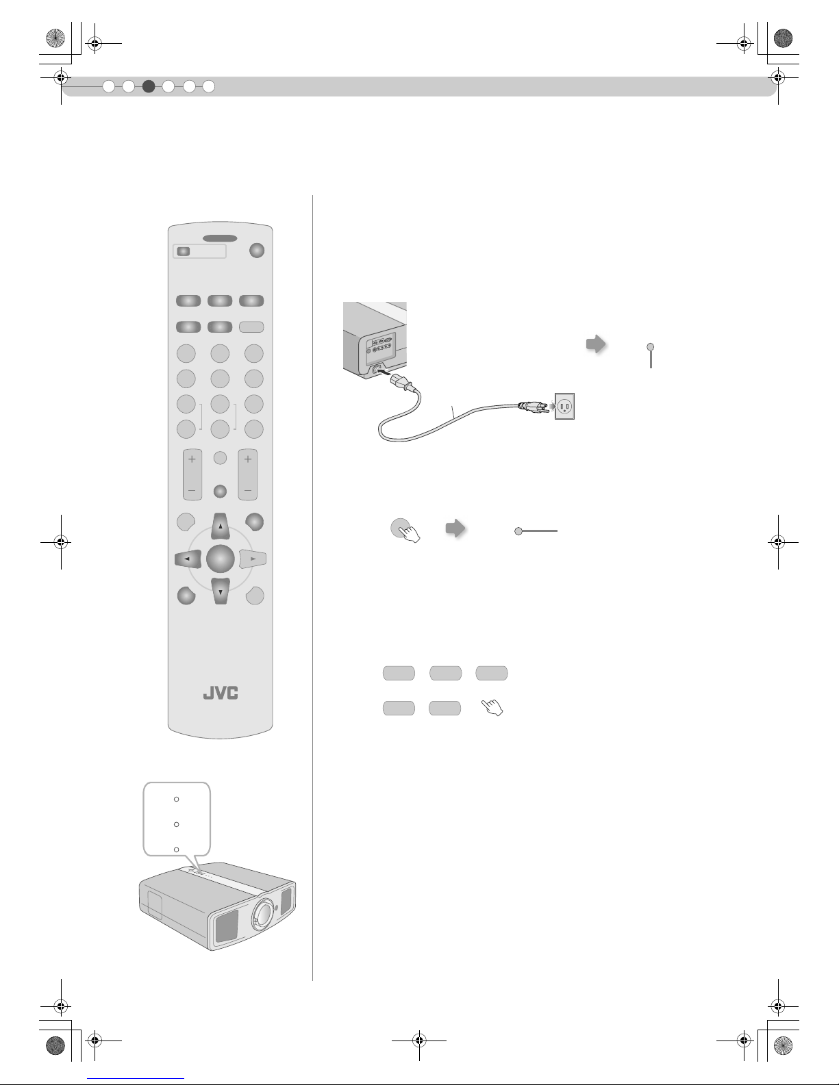
Projecting Image
......................................................................
.
Preparation
z Remove the lens cap.
A Insert the power plug to the power outlet
B Turn on the power
C Project the image
a Select input mode
b Play back the selected device
D Adjust the position of the projection screen
This section describes the basic operations to project input images on the screen.
z You can also press the [STANDBY/ON] button on the unit to turn on the
power. (pP11)
z You can also select the input mode by pressing the [INPUT] button on
the unit. (pP11)
z See “Installing the Projector and Screen” for procedures on adjusting the
position. (pP18)
PROJECTOR
OPERATE
LIGHTTEST
EXIT
SHARP
-
SHARP
+
USER
2
S-VIDEOVIDEO ASPECT
HDMI 2
OFF
........ ........
HDMI 1 COMP.
N
NATURALCINEMA DYNAMIC
COLOR
TEMP
GAMMA
USER
3
D
COLOR
-
COLOR
+
USER
1
C
CONTRAST
BRIGHT
HIDE
INFO
MENU
ENTER
ON
WARNING
LAMP
STANDBY/ON
A
B
Light on (Red)
Power Cord
(Supplied)
A Connect to this unit
B Connect to the power outlet
STANDBY/ON
ON
Light on (Green)
STANDBY/ON
COMP.HDMI 2HDMI 1
VIDEO S-VIDEO
DLA-RS1X_EN.book Page 20 Thursday, February 21, 2008 6:13 PM
Page 19

21
Getting Started Preparation Basic Operation Settings Troubleshooting Others
ENGLISH
E Adjust the image size (zoom)
F Adjust the focus
G Turn off the power
Hold and rotate the tab
z The power cannot be turned off within approximately 90 seconds after it
has been turned on. Start operation only after 90 seconds time.
z You can also press the [STANDBY/ON] button on the unit to turn off the
power. (pP11)
z Put back the lens cap after use to prevent the lens from dirt.
z Pull out the power plug when the unit will not be used for a prolonged time.
Bigger
Smaller
Turn the ring and adjust
You can hide the image
...............................
temporarily
You can hide the image temporarily.
z Press the [HIDE] button again to
display image.
z The power cannot be turned off
when the image is temporarily
hidden.
...............................
About Cool Down mode
z
The Cool Down mode is a function
to cool down the lamp for
approximately 60 seconds after
projection is complete.
This function prevents the internal
parts of the unit from deformation
or damage due to overheating of
the lamp. It also prevents lamp
blowout and premature shortening
of lamp life.
z During Cool Down mode, the
[STANDBY/ON] indicator blinks in
red.
z After the Cool Down mode is
complete, the unit automatically
returns to standby mode.
z Do not pull out the power plug
during Cool Down mode. This may
shorten the lamp life and cause a
malfunction.
TIPS
MEMO
HIDE
STANDBY/ON
Green light blinks when
the image is hidden
STANDBY/ON
STANDBY/ON
OFF
OFF
While a confirmation screen is displayed
Cool Down mode
Light on (Red)
Blinking (Red)
DLA-RS1X_EN.book Page 21 Thursday, February 21, 2008 6:13 PM
Page 20
22
3
Basic Operation
Convenient Features during Projection
The projected image can be set to a most appropriate screen size (aspect
ratio).
z
The screen size can also be set from “Aspect” of the setting menu. (pP29 - S)
z When high definition images are input, the screen size is fixed at “16:9”.
Input Image and Projected Image by Different Screen Size Settings
z
Depending on the input image, selecting “4:3” may result in a vertically stretched
image while selecting “16:9” provides you with the most appropriate screen size.
Images for which quality at the outer area has deteriorated can be projected
by masking (hiding) the surrounding area of the projected image.
A Project the image
You can change the screen size of the projected image or hide the surrounding area of an image for which
quality at the outer area has deteriorated.
Setting the Screen Size
Input Image
Screen Size
4:3 16:9 Zoom
SDTV(4:3)
Aspect Ratio: Same
Most appropriate
screen size
Aspect Ratio:
Landscape
Image is stretched
horizontally
Aspect Ratio: Same
Top and bottom of the
image are missing
SDTV(4:3)
Image recorded in
landscape (black
bands on top and
bottom) of DVD
software
Aspect Ratio: Same
Small image is
projected
Aspect Ratio:
Landscape
Image is stretched
horizontally
Aspect Ratio: Same
Most appropriate
screen size
Masking the Surrounding Area of an Image
PROJECTOR
OPERATE
LIGHTTEST
EXIT
SHARP
-
SHARP
+
USER
2
S-VIDEOVIDEO ASPECT
HDMI 2
OFF
........ ........
HDMI 1 COMP.
N
NATURALCINEMA DYNAMIC
COLOR
TEMP
GAMMA
USER
3
D
COLOR
-
COLOR
+
USER
1
C
CONTRAST
BRIGHT
HIDE
INFO
MENU
ENTER
ON
ASPECT
4:3 16:9 ZOOM
iImage for which quality at the outer
area has deteriorated.
DLA-RS1X_EN.book Page 22 Thursday, February 21, 2008 6:13 PM
Page 21
23
Getting Started Preparation Basic Operation Settings Troubleshooting Others
ENGLISH
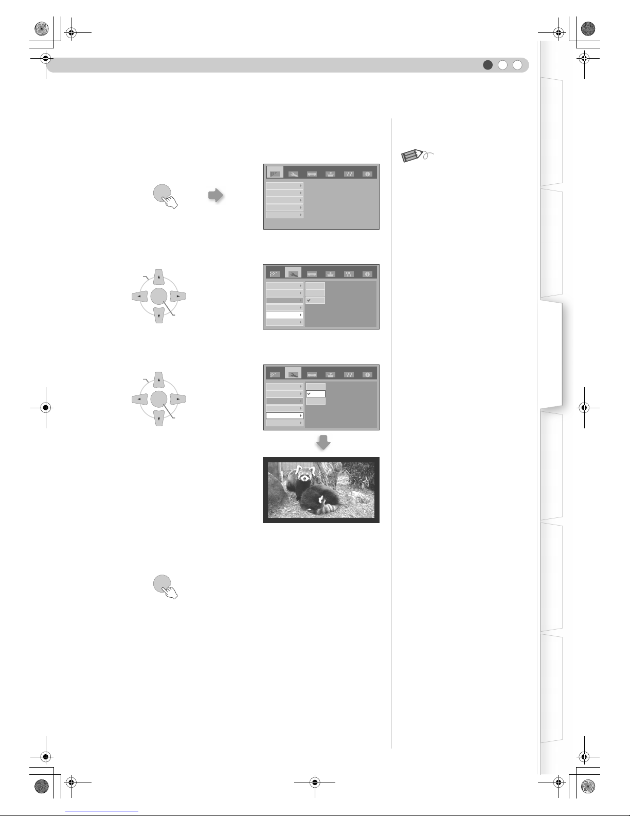
B Mask the image
a Display the setting menu
b Select “Setup” g “Mask”
c Set a mask value
C To end
z Masking is available only when high
definition images are input.
MEMO
Setup
Image
Source Install. Func. Info.
Image Adjust
Color Temp.
Gamma
Offset
Pixel Adjust
MENU
Image Profile
Profile Memory
Picture Position
HDMI Input Level
Mask
SetupImage Source Install. Func. Info.
2.5%
5%
Off
Overscan
ENTER
BCONFIRM
ASELECT
ENTER
BCONFIRM
ASELECT
SetupImage Source Install. Func. Info.
Image Profile
Profile Memory
Picture Position
HDMI Input Level
Mask
2.5%
5%
Off
Overscan
Example:
When the “Mask” value is changed
from “Off” g “5%”
MENU
DLA-RS1X_EN.book Page 23 Thursday, February 21, 2008 6:13 PM
Page 22
24
4
Settings
Setting Menu
Example:
When changing “Aspect” from “4:3” to “16:9”
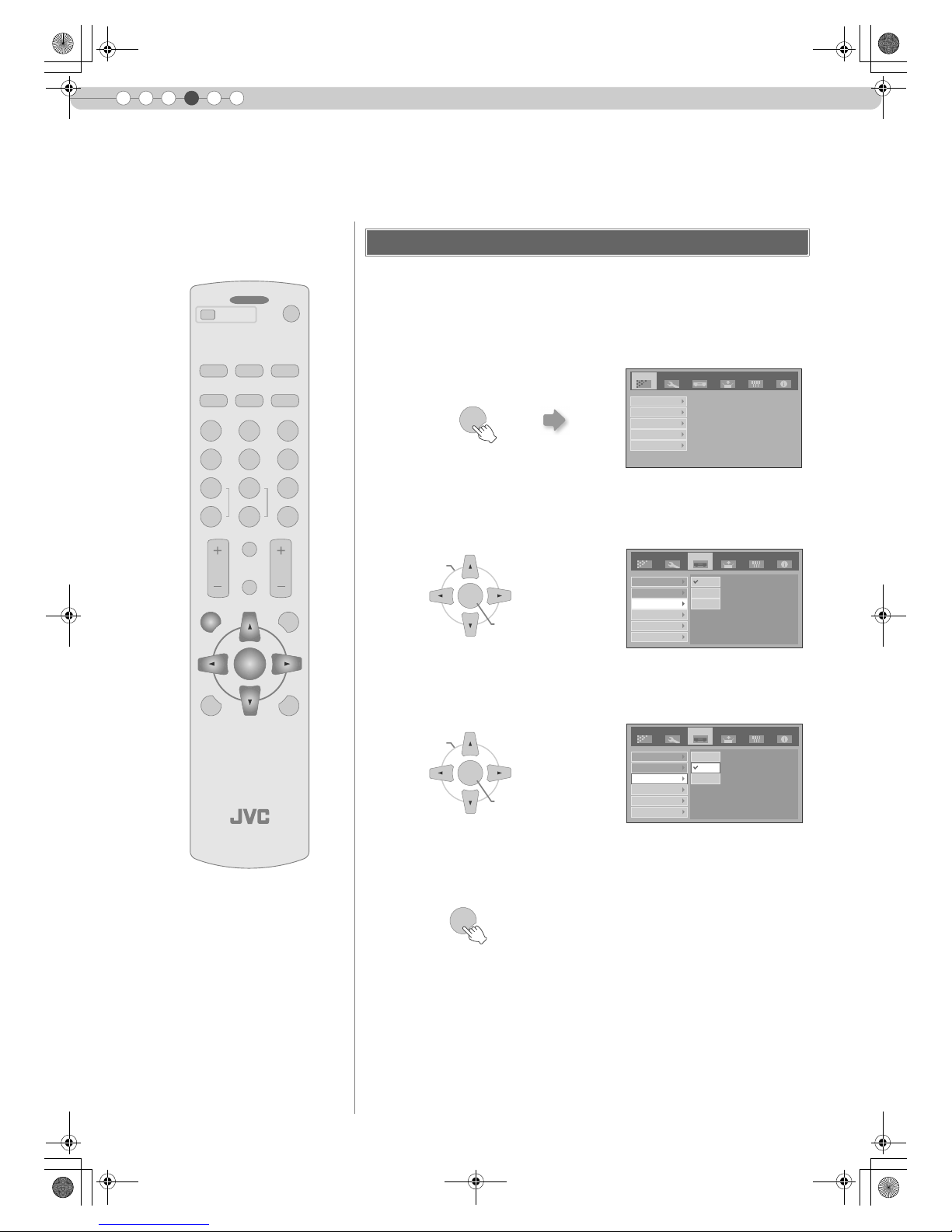
A Display the setting menu
B Select “Source” g “Aspect”
C Set to “16:9”
D To end
Projected images can be adjusted to a desired view by changing the default settings.
Procedures for Menu Operation
PROJECTOR
OPERATE
LIGHTTEST
EXIT
SHARP
-
SHARP
+
USER
2
S-VIDEOVIDEO ASPECT
HDMI 2
OFF
........ ........
HDMI 1 COMP.
N
NATURALCINEMA DYNAMIC
COLOR
TEMP
GAMMA
USER
3
D
COLOR
-
COLOR
+
USER
1
C
CONTRAST
BRIGHT
HIDE
INFO
MENU
ENTER
ON
MENU
Setup
Image
Source Install. Func. Info.
Image Adjust
Color Temp.
Gamma
Offset
Pixel Adjust
Setup
Image
Source Install. Func. Info.
COMP
HDMI
Aspect
Film Mode
Color System
Black Level
4:3
16:9
Zoom
ENTER
BCONFIRM
ASELECT
Setup
Image
Source Install. Func. Info.
COMP
HDMI
Aspect
Film Mode
Color System
Black Level
4:3
16:9
Zoom
ENTER
BCONFIRM
ASELECT
MENU
DLA-RS1X_EN.book Page 24 Thursday, February 21, 2008 6:13 PM
Page 23

25
ENGLISH
Getting Started Preparation Basic Operation Settings Troubleshooting Others
Item values shown in are factory settings.
z Items that can be configured differ according to the input signals.
z “Contrast”, “Brightness”, “Color” and “Sharpness” can also be configured from the remote control. (pP12)
z “Tint” can only be adjusted when NTSC signals are input to the video or S-video input terminal.
* The red, green and blue colors can be adjusted and registered respectively.
z This setting can also be configured from the remote control. (pP12)
Setting Menu
Image > Image Adjust
A Contrast
Adjusts the contrast of the projected image.
(Black) b50 to 50 (White)
B Brightness
Adjusts the brightness of the projected image.
(Darken) b30 to 30 (Brighten)
C Color
Adjusts the color density of the projected image.
(Lighten) b50 to 50 (Darken)
D Tint
Adjusts the hue of the projected image.
(Red) b30 to 30 (Green)
E Sharpness
Adjusts the outline of the projected image.
(Soft) b30 to 30 (Sharp)
F DNR
Adjusts the strength of noise removal of the projected image.
(Weak) 0 to 30 (Strong)
Image > Color Temp.
G Color Temp.
Sets the color temperature of the projected image.
Low Select this to give a reddish tinge to the image.
Middle Select this to have a balanced image.
High Select this to give a bluish tinge to the image.
Memory10
Red (Less red) b255 to 0 (More red)
Green (Less green) b255 to 0 (More green)
Blue (Less blue) b255 to 0 (More blue)
Memory20
Red (Less red) b255 to 0 (More red)
Green (Less green) b255 to 0 (More green)
Blue (Less blue) b255 to 0 (More blue)
DLA-RS1X_EN.book Page 25 Thursday, February 21, 2008 6:13 PM
Page 24
4
26
Setting Menu (Continued)
Settings
z
“Normal” is suitable for normal circumstances but other settings can be selected according to your preferences.
z This setting can also be configured from the remote control. (pP12)
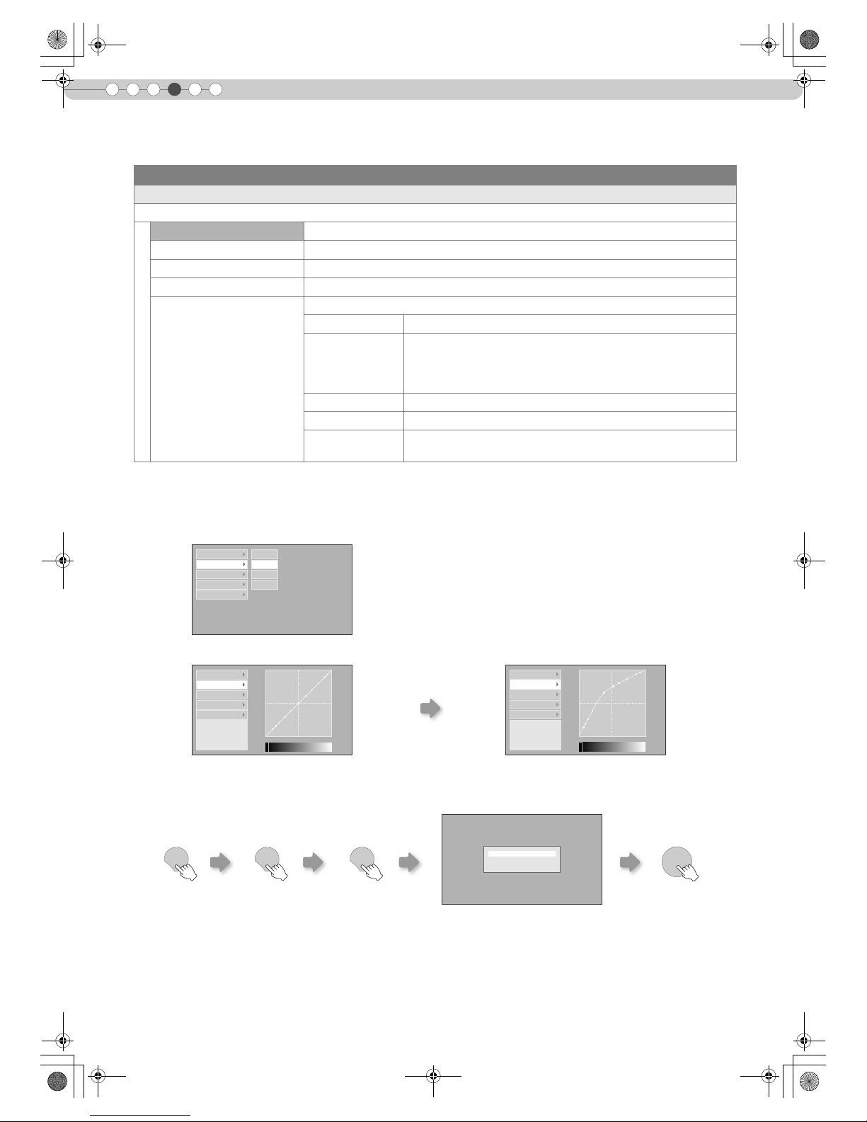
*“Gamma Adjust”
A Select the reference gamma curve coefficient (1.8 to 2.6) in “Correction Value”.
B Select the color to be adjusted in the gamma adjustment screen.
D To end
z If gamma curve is adjusted repeatedly, calculation errors will be accumulated and the gamma curve may not be able to
revert back to its original form. In that case, select the coefficient in “Correction Value” again or retrieve the previous gamma
data using “Load”.
Image > Gamma
H Gamma
Sets the gradation characteristics of the projected image.
Normal For normal circumstances, select this setting.
Theater1 Sets gamma to “Theater1”.
Theater2 Sets gamma to “Theater2”.
Dynamic Select this when in well-lighted areas (such as living room) or when playing games.
Custom
(Gamma Setup)
The gamma can be set according to your preferences.
Correction Value The coefficient (1.8 to 2.6) of the gamma curve can be selected.
Gamma Adjust *
The gamma curve for the colors (R, G, B) can be adjusted
separately.
Adjusting “W” will adjust for all “R, G, B” values. Gamma curves
are represented by a “G”.
Save Saves the adjusted gamma data.
Load Loads the gamma data that was saved.
All Reset
Returns the gamma coefficients to the values set by “Correction
Value”.
1023
512
0 50 100 (%)
Correction Value W
Gamma Adjust R
Save G
Load B
All Reset
Adjustment Point (R)
X: 5 %
Y: 51
Correction Value
Gamma Adjust
Save
Load
All Reset
C Adjust the gamma curve in the gamma curve adjustment screen.
1023
512
0 50 100 (%)
Adjustment Point ( R)
X: 5 %
Y: 51
Correction Value
Gamma Adjust
Save
Load
All Reset
Select the point where the gradation (brightness) is to
be adjusted with the H / I buttons.
Adjust the gradation (brightness) with the
J / K buttons.
EXIT
ENTER
Save gamma data?
Yes : Press [ENTER] button
No : Press [EXIT] button
EXIT EXIT
DLA-RS1X_EN.book Page 26 Thursday, February 21, 2008 6:13 PM
Page 25
27
ENGLISH
Getting Started Preparation Basic Operation Settings Troubleshooting Others
z The horizontal and vertical directions are reversed when the image is flipped to the left or right, or flipped up or down.
z To adjust, use still images with distinct outlines.
z As the adjustments are minor, the effect may be difficult to see for some images.
z This setting can also be configured from the remote control. (pP12)
z “Contrast”, “Brightness”, “Color”, “Sharpness”, “DNR”, “Color Temp.”, “Gamma” and “Offset” are registered in “Image Profile”.
Image > Offset
I Offset
Adjusts the respective brightness of the red, green and blue colors in dark image areas. (Offset level)
Red (Less red) b60 to 60 (More red)
Green (Less green) b60 to 60 (More green)
Blue (Less blue) b60 to 60 (More blue)
Image > Pixel Adjust
J Pixel Adjust
Makes fine adjustments of 1 pixel unit for each minor color shift in the horizontal/vertical direction of the image.
Horiz. Red (Moves red to left) 1 to 7 (Moves red to right)
Horiz. Green (Moves green to left) 1 to 7 (Moves green to right)
Horiz. Blue (Moves blue to left) 1 to 7 (Moves blue to right)
Vert. Red (Moves red down) 1 to 5 (Moves red up)
Vert. Green (Moves green down) 1 to 5 (Moves green up)
Vert. Blue (Moves blue down) 1 to 5 (Moves blue up)
Setup > Image Profile
K Image Profile
Configures the image profile. (pP32)
Cinema Select this to view images with movie quality in a dark room.
Natural Select this to view projected images with quality as-is in a dark room.
Dynamic Select this to view images with clear quality in a bright room.
User1 Selects image profile registered in “User1”.
User2 Selects image profile registered in “User2”.
User3 Selects image profile registered in “User3”.
Setup > Profile Memory
L Profile Memory
Registers or deletes image profiles.
Save User1 Registers image profile in “User1”.
Save User2 Registers image profile in “User2”.
Save User3 Registers image profile in “User3”.
Clear User1 Returns image profile in “User1” to factory setting (natural).
Clear User2 Returns image profile in “User2” to factory setting (natural).
Clear User3 Returns image profile in “User3” to factory setting (natural).
Reset Cinema Returns image profile in “Cinema” to factory setting.
Reset Natural Returns image profile in “Natural” to factory setting.
Reset Dynamic Returns image profile in “Dynamic” to factory setting.
DLA-RS1X_EN.book Page 27 Thursday, February 21, 2008 6:13 PM
Page 26

4
28
Setting Menu (Continued)
Settings
z
The display position value varies with the input signal.
z This adjustment is available only for analog input signals.
z This setting is available only when projecting the HDMI input.
z Masking is available only when high definition images are input.
z This setting is available only when projecting the component video input.
z This setting is available only when projecting the HDMI input.
Setup > Picture Position
M Picture Position
Adjusts the horizontal/vertical position of the projected image.
Setup > HDMI Input Level
N HDMI Input Level
Configures the input level setting of the HDMI input terminal.
Standard For normal circumstances, select this setting.
Enhanced
Select this setting when the black-and-white of the projected image is unclear when
RGB video signals are input from DVI devices.
Setup > Mask
O Mask
Masks (Hides) the outer area of the projected image.
2.5% Masks 2.5 % of the screen.
5% Masks 5 % of the screen.
Off No masking.
Setup > Overscan
P Overscan
Selects whether or not to set overscan for the 4:3 video signals (NTSC, PAL, SECAM, 480i, 576i, 480p and 576p).
Off No overscan.
On Overscans the top, left, bottom and right at 2.5 % each.
Source > COMP
Q COMP
Configures the input signals of the component video input terminals.
Y Pb/Cb Pr/Cr Select this when component video signals are input.
RGB Select this when RGB video signals are input.
SCART
Select this when RGB video signals and sync signals are input from SCART plug for
European market.
Source > HDMI
R HDMI
Configures the input signals of the HDMI input terminal.
Auto Automatically configures input signals.
YCbCr(4:4:4) Select this when Y Cb Cr (4:4:4) video signals are input.
YCbCr(4:2:2) Select this when Y Cb Cr (4:2:2) video signals are input.
RGB Select this when RGB video signals are input.
DLA-RS1X_EN.book Page 28 Thursday, February 21, 2008 6:13 PM
Page 27
29
ENGLISH
Getting Started Preparation Basic Operation Settings Troubleshooting Others
z When high definition images are input, the screen size is fixed at “16:9”.
z This setting can also be configured from the remote control. (pP12, 22)
z This setting is available only when projecting the video or S-video input.
z This setting can only be adjusted when NTSC signals are input to the video or S-video input terminal.
Source > Aspect
S Aspect
Configures the screen size (aspect ratio) of the projected image.
4:3 Sets screen size of the projected image to 4:3.
16:9 Sets screen size of the projected image to 16:9.
Zoom Zooms the image.
Source > Film Mode
T Film Mode
Select this to view movies shot on film.
Auto For normal circumstances, select this setting.
Off Select this when you are not watching movies shot on film.
Source > Color System
U Color System
Configures the color system.
Auto Configures the color system automatically.
NTSC Select this when the color system is NTSC.
NTSC4.43 Select this when the color system is NTSC4.43.
PAL Select this when the color system is PAL.
PAL-M Select this when the color system is PAL-M.
PAL-N Select this when the color system is PAL-N.
SECAM Select this when the color system is SECAM.
Source > Black Level
V Black Level
Configures the black level.
0 %
Select this when the gradation of the dark portions of an image is indistinct with the
7.5 % setting.
7.5 % Select this when the dark portions of an image appear washed out with the 0 % setting.
Install. > Menu Position
W Menu Position
Sets the display position of the menu.
Upper left Displays menu on the upper left of the screen.
Upper center Displays menu on the upper center of the screen.
Upper right Displays menu on the upper right of the screen.
Left center Displays menu on the left center of the screen.
Center Displays menu on the center of the screen.
Right center Displays menu on the right center of the screen.
Lower left Displays menu on the lower left of the screen.
Lower center Displays menu on the lower center of the screen.
Lower right Displays menu on the lower right of the screen.
DLA-RS1X_EN.book Page 29 Thursday, February 21, 2008 6:13 PM
Page 28

4
30
Setting Menu (Continued)
Settings
Install. > Menu Display
X Menu Display
Sets the duration for displaying the menu.
15 sec Displays for 15 seconds.
On Always display.
Install. > Line Display
a Line Display
Sets whether to display the input when switching input.
5 sec Displays for 5 seconds.
Off Do not display.
Install. > Flip H
b Flip H
Select this when the image is projected from the back of the screen or when the projector is hung from the ceiling.
On Flips image to the left or right.
Off Do not flip image to the left or right.
Install. > Flip V
c Flip V
Select this when the projector is hung from the ceiling.
On Flips image up or down.
Off Do not flip image up or down.
Install. > High Altitude Mode
d High Altitude Mode
Select this when using the projector in a location of low atmospheric pressure (higher than 900 meters above sea level).
On Activate.
Off Do not activate.
Func. > Back Color
e Back Color
Configures the screen color displayed when there is no input signal.
Blue Sets screen color to “Blue”.
Black Sets screen color to “Black”.
Func. > Sleep Timer
f Sleep Timer
Sets the lapse time before automatically switching to the standby mode when there is no input signal.
15 Switch to standby mode after 15 minutes.
30 Switch to standby mode after 30 minutes.
60 Switch to standby mode after 60 minutes.
Off Do not switch to standby mode.
DLA-RS1X_EN.book Page 30 Thursday, February 21, 2008 6:13 PM
Page 29

31
ENGLISH
Getting Started Preparation Basic Operation Settings Troubleshooting Others
z Changing the lamp power will not change the lamp time (lamp life).
z The setting cannot be changed within approximately 90 seconds after this unit has been turned on.
z Settings cannot be changed within approximately 60 seconds after they are made.
z This can also be displayed from the remote control. (pP12)
z This can also be displayed from the remote control. (pP12)
Func. > Logo
g Logo
Sets whether to display “Logo” during startup.
Off Do not display.
On Displays for 5 seconds.
Func. > Lamp Power
h Lamp Power
Configures the output of the light-source lamp.
Normal For normal circumstances, select this setting. (170 W)
High Select this when it is difficult to see the image in a bright room. (200 W)
Func. > Test Pattern
i Test Pattern
Displays 6 types of test patterns.
Func. > Language
j Language
Sets the language of the menu display.
日本語 Japanese
English English
Deutsch German
Español Spanish
Italiano Italian
Français French
Português Portuguese
Nederlands Dutch
Svenska Swedish
Norsk Norwegian
中文 Chinese (Simplified)
Info.
k Input
Displays the currently selected video input.
l Format
Displays the types of the current input video signals.
m Lamp Time
Displays the accumulated hours of usage of the light-source lamp.
DLA-RS1X_EN.book Page 31 Thursday, February 21, 2008 6:13 PM
Page 30

32
4
Settings
Customizing Projected Images
“Contrast”, “Brightness”, “Color”, “Sharpness”, “DNR”, “Color Temp.”, “Gamma” and
“Offset” are registered in the image profile.
A Select the image profile
B Adjust image quality
Example: To adjust “Contrast”
a Display the setting menu
b Select “Image” g “Image Adjust” g “Contrast”
c Adjust the setting
d To end the adjustments
C Other items can also be adjusted
D To end
You can adjust the projected image to a desired image quality and register the adjusted value. (Image
Profile) Besides the default “Cinema”, “Natural” and “Dynamic” settings, there are 3 more types of userdefined settings for image profile.
Changing the Default Image Profile Values
PROJECTOR
OPERATE
LIGHTTEST
EXIT
SHARP
-
SHARP
+
USER
2
S-VIDEOVIDEO ASPECT
HDMI 2
OFF
........ ........
HDMI 1 COMP.
N
NATURALCINEMA DYNAMIC
COLOR
TEMP
GAMMA
USER
3
D
COLOR
-
COLOR
+
USER
1
C
CONTRAST
BRIGHT
HIDE
INFO
MENU
ENTER
ON
CINEMACNATURALNDYNAMIC
D
MENU
ENTER
SELECT
0
0
0
4
0
0
Setup
Image
Source Install. Func. Info.
Image Adjust
Color Temp.
Gamma
Offset
Pixel Adjust
Contrast
Brightness
Color
Tint
Sharpness
DNR
0
ENTER
ADJUST
Contrast
EXIT
MENU
z “Contrast”, “Brightness”, “Color”, “Sharpness”, “Color Temp.”
and “Gamma” can also be adjusted from the remote control.
(pP12)
z To return to the default values, reset the registered settings
with “Profile Memory” in the setting menu. (pP27 - L)
DLA-RS1X_EN.book Page 32 Thursday, February 21, 2008 6:13 PM
Page 31

33
ENGLISH
Getting Started Preparation Basic Operation Settings Troubleshooting Others
A Select the image profile
B Adjust image quality
C Register the image profile
a Display the setting menu
b Select “Setup” g “Profile Memory”
c Register the setting
D To end
Registering User-defined Image Profiles
z See “Changing the Default Image Profile Values” for procedures on
adjusting the image quality. (pP32)
z To return to the default values, reset the registered settings with “Profile
Memory” in the setting menu. (pP27 - L)
USER1USER2USER
3
z Adjustment settings of image
quality will not be registered if other
image profiles are selected before
registering these settings.
CAUTION
MENU
Setup
Image
Source Install. Func. Info.
Image Profile
Profile Memory
Picture Position
HDMI Input Level
Mask
Save User1
Save User2
Save User3
Clear User1
Clear User2
Clear User3
Reset Cinema
Reset Natural
Reset Dynamic
ENTER
BCONFIRM
ASELECT
Setup
Image
Source Install. Func. Info.
Image Profile
Profile Memory
Picture Position
HDMI Input Level
Mask
Save User1
Save User2
Save User3
Clear User1
Clear User2
Clear User3
Reset Cinema
Reset Natural
Reset Dynamic
ENTER
BCONFIRM
ASELECT
MENU
DLA-RS1X_EN.book Page 33 Thursday, February 21, 2008 6:13 PM
Page 32
5
34
Troubleshooting
Troubleshooting
Before sending the unit to your authorized dealer for repair, check the following points.
The following situations are not malfunctions.
You do not need to worry under the following situations if there is no abnormality on the screen.
z Part of the top surface or front of the unit is hot.
z A creaking sound is heard from the unit.
z An operating sound is heard from the internal of the unit.
Perform the following operations when the unit is unable to operate normally due to external static or noises.
A When the unit is in standby mode, pull out the power plug, then insert again.
B Press the power button on the unit to turn on the power again.
A sound may be heard when the lamp is off but there is no danger.
D-ILA device is manufactured using high-precision technology but there may be some missing pixels or pixels that remain
permanently lit up.
Power is not supplied
Is the power cord disconnected? Insert the power cord (plug) firmly. pP20
Is the lamp cover properly shut?
Remove the power plug when the unit is in standby mode and
close the lamp cover properly. After that, insert the plug
again.
pP39
Is the lamp in Cool Down mode?
After the Cool Down mode is complete, turn on the power
again.
pP21
Projected image is dark
Is the lamp near exhaustion?
Check the lamp time on the information menu. Prepare a new
lamp unit or replace as soon as possible when the lamp is near
exhaustion.
pP38 - 40
The unit works when power is turned on but stops abruptly after a few minutes
Are the air inlets and exhaust vent
blocked?
Remove the power plug when the unit is in standby mode and
remove any blocking object. After that, insert the plug again.
pP2, 10
Is the filter dirty? Clean the filter. pP41
Video image does not appear
Is the lens cap removed? Remove the lens cap. pP20
Is the correct external input selected? Select the correct external input. pP20
Is the AV device properly connected? Connect the AV device properly. pP14 - 17
Is the power of the AV device turned on? Turn on the power of the AV device and play the video. pP20
Are the correct signals being output from
the AV device?
Set the AV device properly. pP14 - 17
Is the setting of the input terminal correct?
Set “COMP” and “HDMI” in the setting menu according to the
input signal.
pP28 - Q
pP28 - R
Is the video image temporarily hidden? Press the [HIDE] button to display the video image again. pP21
Color does not appear or looks strange
Is the image correctly adjusted? Adjust “Color” and “Tint” in the setting menu. pP25 - CD
DLA-RS1X_EN.book Page 34 Thursday, February 21, 2008 6:13 PM
Page 33
35
ENGLISH
Getting Started Preparation Basic Operation Settings Troubleshooting Others
Video image is fuzzy
Is the focus correctly adjusted? Adjust accordingly using the focus adjustment ring. pP21
Is the unit placed too near or too far away
from the screen?
Set the unit at a correct distance from the screen. pP18, 19
Video images are missing
Has setting been performed for screen
mask?
Set “Mask” in the setting menu to “Off”. pP23, 28 - O
Is the display out of position?
Alter the “Picture Position” value in the setting menu to ensure
that images are not missing.
pP28 - M
Remote control does not work
Are batteries installed correctly?
Match the polarities (+ or -) correctly when inserting the
batteries.
pP13
Are batteries exhausted? Replace with new batteries. pP13
Is there an obstructive object between the
remote control and remote sensor?
Remove any obstructive objects. pP13
Is the remote control held too far away
from the unit?
Hold the remote control closer to the sensor when using. pP13
Power is cut off suddenly
Has setting been performed for sleep
time?
Set “Sleep Timer” in the setting menu to “Off”. pP30 - f
DLA-RS1X_EN.book Page 35 Thursday, February 21, 2008 6:13 PM
Page 34
5
36
Troubleshooting
What to Do When These Messages
Are Displayed
Message Cause (Details)
No device is connected to the input terminal.
The input terminal is connected but there is no signal.
gInput the video signals.
A video signal that cannot be used in this unit has been input.
gInput video signals that can be used.
The message is displayed when the accumulated lamp time has exceeded
1900 hours.
To clear the message, press the [EXIT] button.
gGet ready a new lamp unit and replace as soon as possible.
The message is displayed when the accumulated lamp time has exceeded
2000 hours.
The message is displayed each time during projection.
To clear the message, press the [EXIT] button.
gReplace with a new lamp unit and reset the lamp time. (pP38 - 40)
COMP
No input
HDMI-2
Out of range
EXIT
Lamp replacement
EXIT
Warning
Lamp replacement
DLA-RS1X_EN.book Page 36 Thursday, February 21, 2008 6:13 PM
Page 35
37
ENGLISH
Getting Started Preparation Basic Operation Settings Troubleshooting Others
About Warning Indicators
The accumulated lamp time or warning mode of this unit is displayed by the indicators.
For information on indicator display during normal operation, see “Controls and Features” (pP10).
When the unit enters into warning mode (No. 3 to 10), it will automatically stop projection and run the cooling fan for
about 60 seconds.
After the cooling fan has stopped, pull out the power plug from the power outlet.
Then, follow the procedures below.
If the warning indication is displayed again, wait for the cooling fan to stop. Then pull out the power plug from the power outlet.
Call your authorized dealer for repair.
No.
Indicator
Content
LAMP WARNING
1
Light on b
Lamp replacement is near (pP38 - 40)
(When accumulated lamp time has exceeded 1900 hours)
2
Lamp has reached end of life (pP38 - 40)
(When accumulated lamp time has exceeded 2000 hours)
3
Blinking Light on
Lamp does not light up and unit is unable to project
4 Lamp is turned off during projection
5 Lamp cover is removed
6
b Light on
There is an error in the circuit operation
(Operation error in microcomputer circuit)
7
There is an error in the circuit operation
(Operation error in drive circuit)
8
Internal temperature is abnormally high
(Internal temperature error)
9
External temperature is high
(External temperature error)
10
Cooling fan has stopped
(Fan locked)
Actions to Be Taken for Warning Mode
No. Check Action
3
z Check that an impact shock has not occurred during
operation.
z Check that the lamp unit and lamp cover are correctly
installed.
Turn on the power again.
4
5
6
z Check that nothing is blocking the air inlets.
z Check that the external temperature is normal.
Leave the unit until it cools down.
After that, turn on the power again.
7
8
9
10
DLA-RS1X_EN.book Page 37 Thursday, February 21, 2008 6:13 PM
Page 36
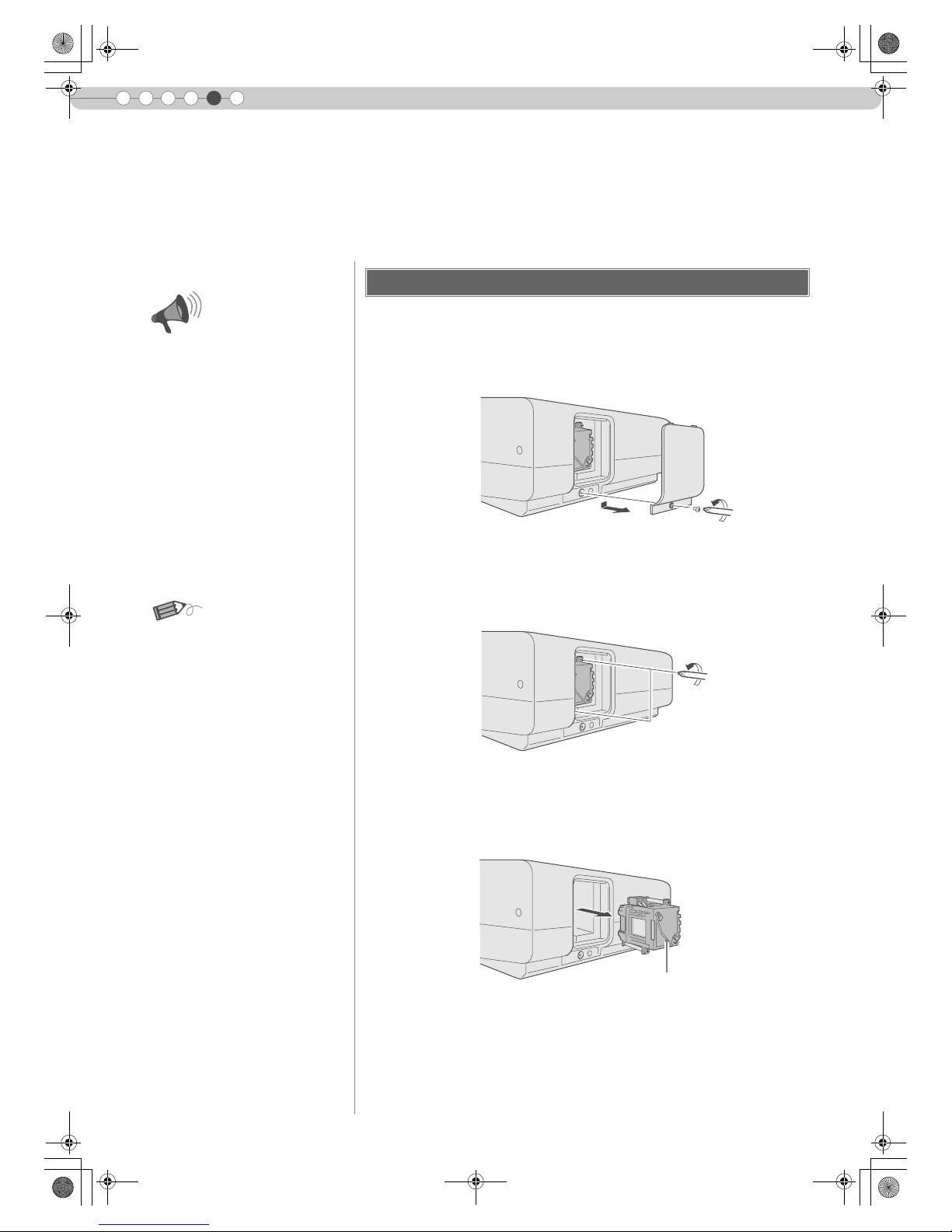
38
5
Troubleshooting
Replacing the Lamp
A Remove the lamp cover
B Loosen the screws on the lamp unit
C Pull out the lamp unit
The lamp is a consumable item. If the image is dark or the lamp is turned off, replace the lamp unit.
z
When the lamp replacement time approaches, a message is displayed on the screen and the condition is indicated by the
indicator. (pP36, 37)
Procedure for Lamp Replacement
z Remove the screws with a + screwdriver.
z Loosen the screws with a + screwdriver.
z Grasp the handle and pull out the lamp unit.
z Pull the power plug from the power
outlet. Failure to do so may cause
injuries or electric shocks.
z Do not replace the lamp
immediately after the unit has been
used. Allow a cooling period of 1
hour or more before replacement.
The temperature of the lamp is still
high and this may cause a burn.
z Do not apply shock to the lamp
unit. It may cause lamp blowout.
z Do not use flammable air duster to
clean the internal parts of the unit.
This may cause fire.
...............................
Usable Lamp Life
z
The usable lamp life for this unit is
approximately 2000 hours. The
usable lamp life of 2000 hours is
merely the average usable life of
lamps and we do not provide any
guarantee for this figure.
z The lamp life may not reach 2000
hours depending on the operating
conditions.
z When the lamp has reached the
end of its usable life, deterioration
progresses rapidly.
z If the image is dark or the color
tone is abnormal, replace the lamp
unit as soon as possible.
...............................
Purchasing the Lamp Unit
Please consult your authorized
dealer.
Lamp Unit
Part No. : BHL5009-S
CAUTION
MEMO
Handle
DLA-RS1X_EN.book Page 38 Thursday, February 21, 2008 6:13 PM
Page 37
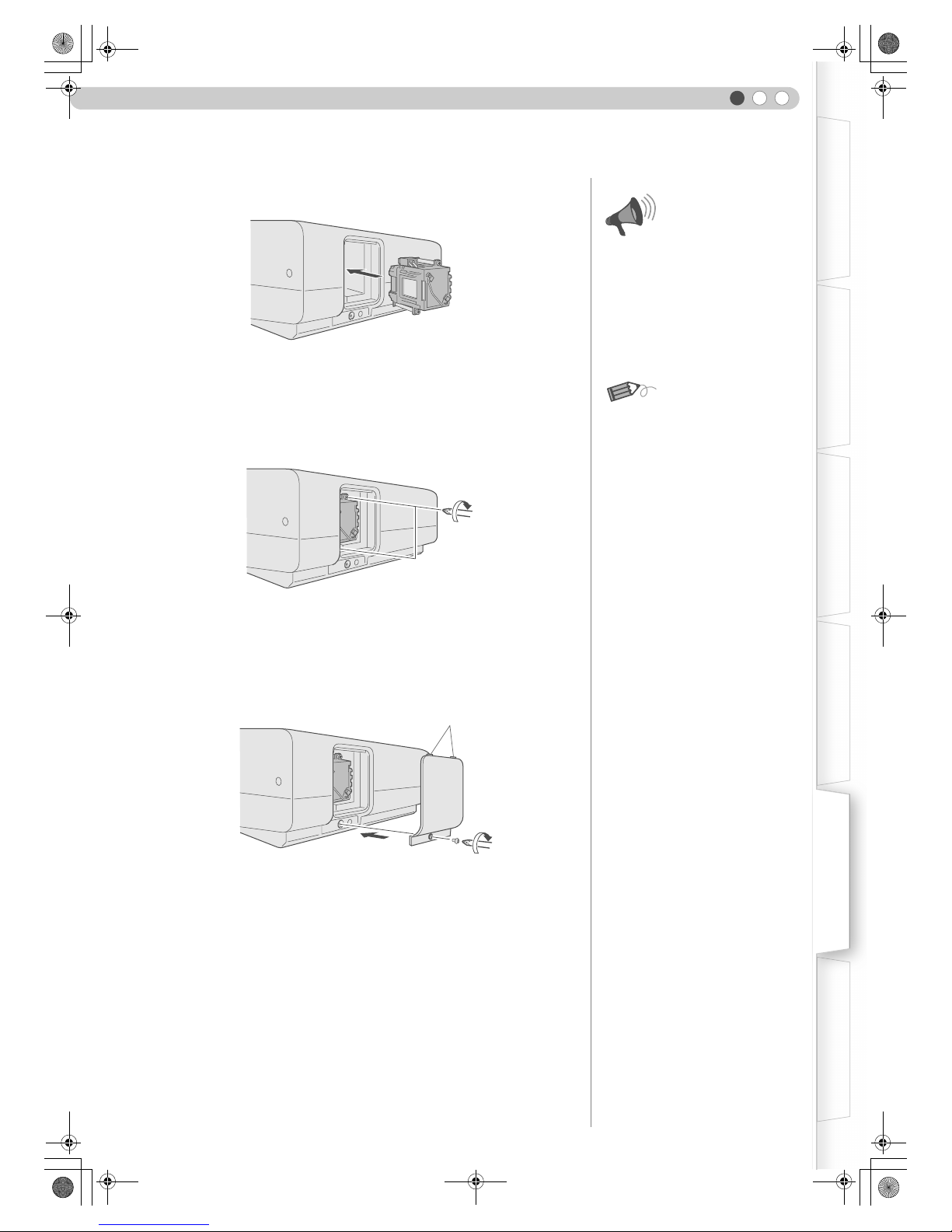
39
ENGLISH
Getting Started Preparation Basic Operation Settings Troubleshooting Others
D Install the new lamp unit
E Tighten the screws of the lamp unit
F Attach the lamp cover
z Fasten the screws with a + screwdriver.
z Insert the top part (with 2 claws) of the lamp cover into the unit.
z Fasten the screws with a + screwdriver.
z Use only genuine replacement
parts for the lamp unit. Also, never
attempt to re-use an old lamp unit.
This may cause a malfunction.
z Do not touch the surface of a new
lamp. This may shorten the lamp
life and cause lamp blowout.
...............................
After Replacing the Lamp
z
Do not place the removed lamp
unit at locations reachable by
children or near combustible items.
z Dispose used lamp units in the
same way as fluorescent lamps.
Follow your local community rules
for disposal.
CAUTION
MEMO
Claws
DLA-RS1X_EN.book Page 39 Thursday, February 21, 2008 6:13 PM
Page 38

40
Replacing the Lamp (Continued)
5
Troubleshooting
After installing a new lamp unit, reset the lamp time.
A Insert the power plug to the power outlet
B Reset lamp time
Resetting Lamp Time
z The [LAMP] indicator and [STANDBY/ON] indicator blink alternately for 3
seconds. After that, the unit switches to standby mode.
PROJECTOR
OPERATE
LIGHTTEST
EXIT
SHARP
-
SHARP
+
USER
2
S-VIDEOVIDEO ASPECT
HDMI 2
OFF
........ ........
HDMI 1 COMP.
N
NATURALCINEMA DYNAMIC
COLOR
TEMP
GAMMA
USER
3
D
COLOR
-
COLOR
+
USER
1
C
CONTRAST
BRIGHT
HIDE
INFO
MENU
ENTER
ON
WARNING
LAMP
STANDBY/ON
z Reset the lamp time only when you
have replaced the lamp.
z Never reset it when the lamp is still
in use. Otherwise, the approximate
standard for gauging replacement
time may be inaccurate and lamp
blowout may occur.
CAUTION
Light on (Red)
STANDBY/ON
EXIT
ENTER
HIDE
Press for 2 seconds or more
z Press in the order as shown.
z Press each button within 2-second intervals and press the last button for 2
seconds or more.
DLA-RS1X_EN.book Page 40 Thursday, February 21, 2008 6:13 PM
Page 39
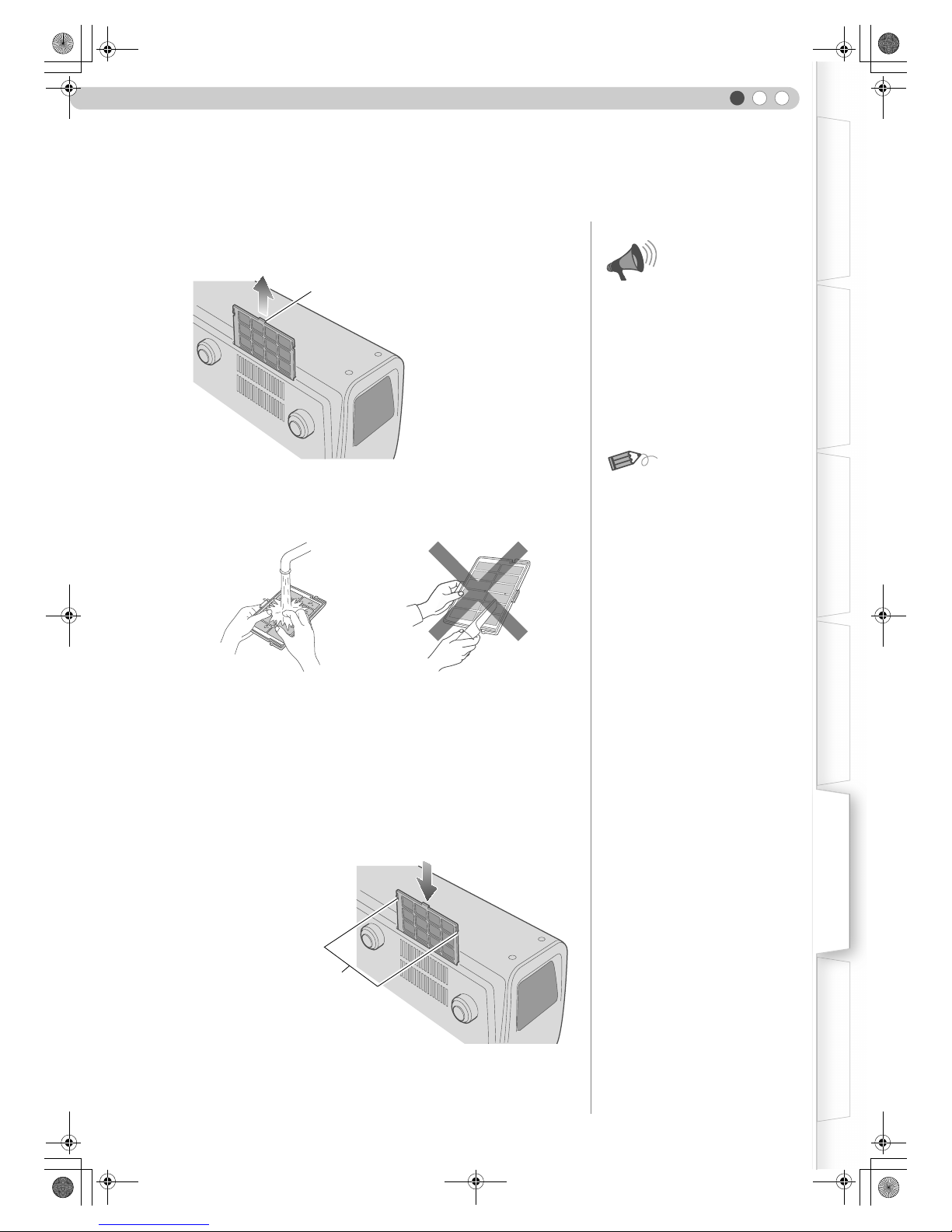
41
ENGLISH
Getting Started Preparation Basic Operation Settings Troubleshooting Others
Cleaning and Replacing the Filter
A Remove the inner filter
B Clean the filter
C Reinstall the inner filter
Clean the filter regularly or air intake efficiency may deteriorate and malfunction may occur.
z Wash the filter with water and dry it in a shaded area.
z In extremely soiled cases, use of a neutral detergent is recommended.
Put on rubber gloves when using a neutral detergent.
z After washing the filter with water, make sure that it is completely dry before
reinstalling. Otherwise, electric shocks or malfunctions may occur.
z Do not clean the filter with a vacuum cleaner or air duster. The filter is soft
and may be damaged.
Lift up while pushing the claw
z Pull the power plug from the power
outlet.
If the filter is damaged or too
...............................
dirty to be cleaned
z
Replace with a new filter. A dirty
filter will dirty the internal parts of
the unit and cause shadows on the
video image.
z To purchase a new filter or when
there is dirt in the internal parts,
consult your authorized dealer.
Inner Filter
Part No. : LC32058-002A
CAUTION
MEMO
Check that the left and right
claws are locked onto the unit
DLA-RS1X_EN.book Page 41 Thursday, February 21, 2008 6:13 PM
Page 40
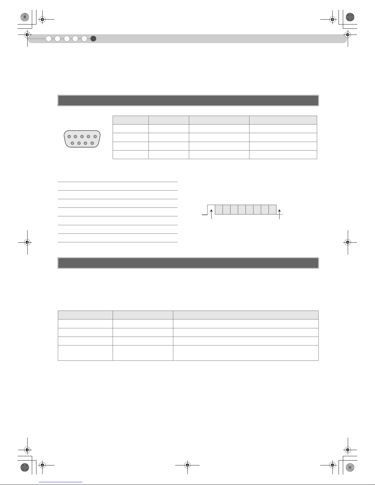
6
42
Others
RS-232C Interface
Control of this unit via a computer is possible by connecting the computer to this unit with a RS-232C cross
cable (D-Sub 9 pin).
The command between this unit and the computer consists of “Header”, “Unit ID”, “Command”, “Data” and “End”.
z
Header (1 byte), Unit ID (2 bytes), Command (2 bytes), Data (n bytes), End (1 byte)
Header
This binary code indicates the start of communication.
Unit ID
This code specifies the unit. The binary code is fixed at “8901”.
RS-232C Specifications
Pin No. Signal Operation Signal Direction
2 RxD Receive data This unit PC
3 TxD Transmit data This unit PC
5 GND Signal ground b
1, 4, 6 b 9N/C bb
z PC refers to the controller such as a personal computer.
Mode Non-synchronous
Character Length 8 bit
Parity None
Start Bit 1
Stop Bit 1
Data Rate 19200 bps
Data Format Binary
Command Format
Binary code Type Description
21 Operating command PC This unit
3F Reference command PC This unit
40 Response command This unit PC
06 ACK
This unit PC
(When the command is accepted without error, it returns to PC)
1
6
5
9
This unit
D6 D7D4 D5D2 D3D0 D1
Start Bit Stop Bit
DLA-RS1X_EN.book Page 42 Thursday, February 21, 2008 6:13 PM
Page 41
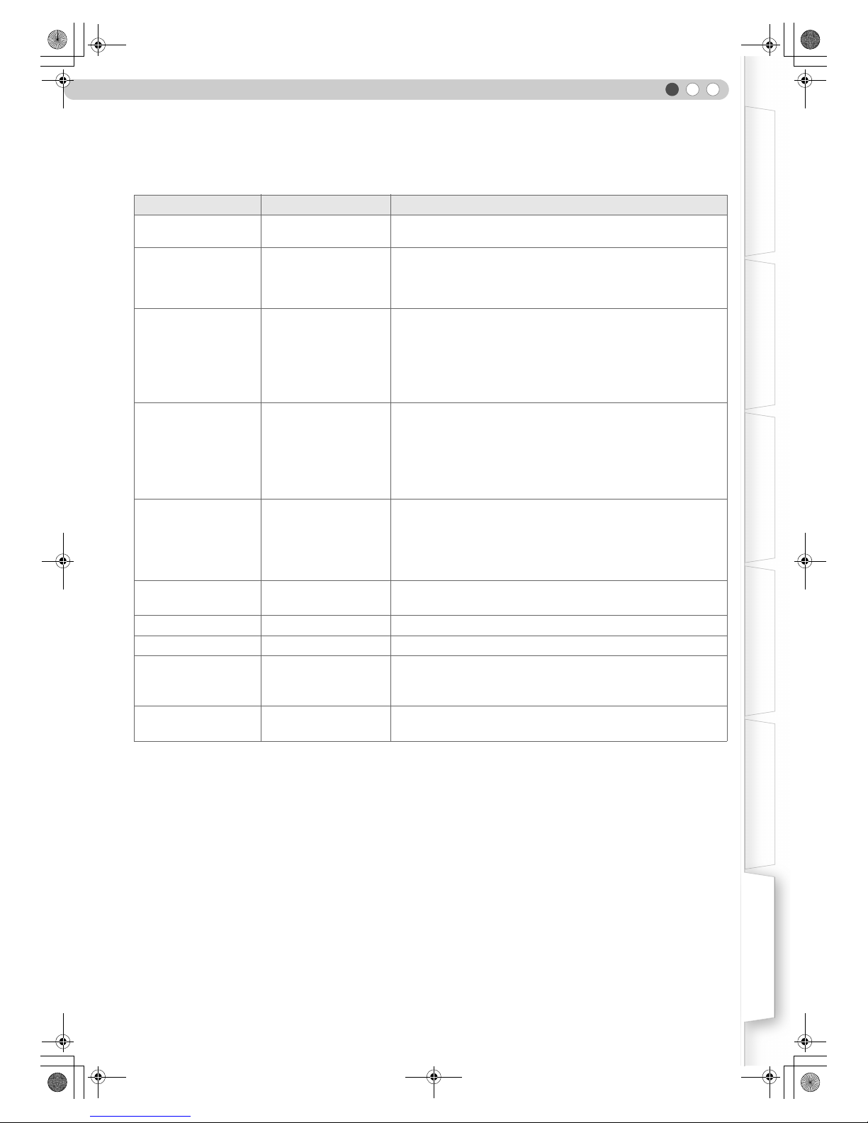
43
ENGLISH
Getting Started Preparation Basic Operation Settings Troubleshooting Others
Command and data
Operating command and data (Binary code)
Command Type Data description
0000 Connection check
Checks whether communication is available between this unit and
the PC during standby.
5057 Power supply
During standby
31 : Turns on the power.
During power on
30 : Turns off the power. (Standby mode)
4950 Input
During power on
30 : S-VIDEO
31 : VIDEO
32 : COMP.
36 : HDMI 1
37 : HDMI 2
4754 Gamma table
During power on
30 : Switches to “Normal”.
31 : Switches to “Theater1”.
32 : Switches to “Theater2”.
33 : Switches to “Dynamic”.
34 : Switches to “Custom”.
4750 Gamma coefficient
30 : 1.8 35 : 2.3
31 : 1.9 36 : 2.4
32 : 2.0 37 : 2.5
33 : 2.1 38 : 2.6
34 : 2.2
4752 Gamma data (R)
Sets the gradation (0 to 1023) of the output signal in hexadecimal.
The data is 16 bit (2 byte) with the 2 byte data in the high/low order.
4747 Gamma data (G) Same as gamma data (R).
4742 Gamma data (B) Same as gamma data (R).
5453 Test pattern
During power on
30 : Do not display.
36 : Displays staircase (gray).
5243 Remote Control
Sends the same code as the supplied remote control.
z “Remote control code” (pP45)
DLA-RS1X_EN.book Page 43 Thursday, February 21, 2008 6:13 PM
Page 42

44
RS-232C Interface (Continued)
6
Others
Reference command and data (Binary code)
End
This code indicates the end of communication. The binary code is fixed at “0A”.
Command Type Data description
5057 Power supply
During standby or power on
30 : Standby mode
31 : Power-on mode
32 : During Cool Down mode
34 : Warning mode
4950 Input
During power on
30 : S-VIDEO
31 : VIDEO
32 : COMP.
36 : HDMI 1
37 : HDMI 2
4754 Gamma table
During power on
30 : “Normal”
31 : “Theater1”
32 : “Theater2”
33 : “Dynamic”
34 : “Custom”
4750 Gamma coefficient
30 : 1.8 35 : 2.3
31 : 1.9 36 : 2.4
32 : 2.0 37 : 2.5
33 : 2.1 38 : 2.6
34 : 2.2
4752 Gamma data (R) Gradation of the output signal (0 to 1023)
4747 Gamma data (G) Gradation of the output signal (0 to 1023)
4742 Gamma data (B) Gradation of the output signal (0 to 1023)
5453 Test pattern
During power on
30 : Do not display.
36 : Staircase (gray).
DLA-RS1X_EN.book Page 44 Thursday, February 21, 2008 6:13 PM
Page 43
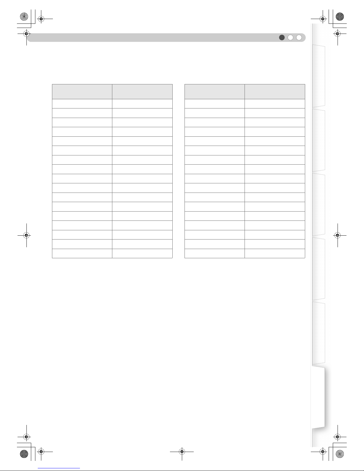
45
ENGLISH
Getting Started Preparation Basic Operation Settings Troubleshooting Others
Remote control code
z Binary code is sent during communication.
Remote control button
name
Binary code
Remote control button
name
Binary code
J 37 33 30 31 USER1 37 33 36 43
K 37 33 30 32 USER2 37 33 36 44
EXIT 37 33 30 33 USER3 37 33 36 45
OPERATE ON 37 33 30 35 HDMI 1 37 33 37 30
OPERATE OFF 37333036 HDMI 2 37333731
HIDE 37 33 31 44 INFO 37 33 37 34
MENU 37 33 32 45 GAMMA 37 33 37 35
ENTER 37 33 32 46 COLOR TEMP 37 33 37 36
I 37 33 33 34 ASPECT 37 33 37 37
H 37 33 33 36 CONTRAST (a) 37333738
VIDEO 37333442 CONTRAST (b) 37333739
S-VIDEO 37333443 BRIGHT (a) 37333741
COMP. 37333444 BRIGHT (b) 37333742
TEST 37 33 35 39 COLOR (a) 37333743
CINEMA 37 33 36 39 COLOR (b) 37333744
NATURAL 37 33 36 41 SHARP (a) 37333745
DYNAMIC 37333642 SHARP (b) 37333746
DLA-RS1X_EN.book Page 45 Thursday, February 21, 2008 6:13 PM
Page 44

6
46
Others
This section shows the communication examples of RS-232C.
Operating command
Reference command
RS-232C Communication Examples
Type Command Description
Connection check
PC This unit:21890100000A
This unit PC: 06 89 01 00 00 0A
Checks connection
Power (On)
PC This unit: 21 89 01 50 57 31 0A
This unit PC: 06 89 01 50 57 0A
When power is turned on from standby mode
Power (Off)
PC This unit: 21 89 01 50 57 30 0A
This unit PC:06890150570A
When power is turned off (standby mode)
from power-on mode
Input (COMP.)
PC This unit:2189014950 32 0A
This unit PC: 06 89 01 49 50 0A
When video input is set to component
Remote Control
(MENU)
PC This unit: 21 89 01 52 43 37 33 32 45 0A
This unit PC:06890152430A
When the same operation as pressing the
[MENU] button on the remote control is made
Type Command Description
Power (On)
PC This unit:3F890150570A
This unit PC: 06 89 01 50 57 0A
This unit PC:4089015057310A
When information on power-on mode is
acquired
Input (S-VIDEO)
PC This unit:3F890149500A
This unit PC:06890149500A
This unit PC:4089014950300A
When information on S-VIDEO input is
acquired
DLA-RS1X_EN.book Page 46 Thursday, February 21, 2008 6:13 PM
Page 45

47
ENGLISH
Getting Started Preparation Basic Operation Settings Troubleshooting Others
Copyright and Caution
z HDMI, HDMI logo and high definition multimedia interface
are trademarks or registered trademarks of HDMI
Licensing LCC.
z This product uses Ricoh TrueType fonts manufactured
and sold by Ricoh Co., Ltd.
..................................................
D-ILA Device Characteristics
Do not project still pictures or pictures that have still
segments for a long period of time. The still parts of the
picture may remain on the screen. This is a characteristic of
D-ILA devices and not a malfunction. The picture will
disappear over time.
..................................................
When Unit is Unused for a Long Time
Prolonged disuse of the unit may effect an error on the
functions. Turn on the power occasionally and operate the
unit.
..................................................
Viewing Advice
Looking at the screen continually for a prolonged time will
cause your eyes to get tired. Allow your eyes to rest at
intervals.
..................................................
Usage Environment
z Avoid direct exposure of screen to direct sunlight and
illumination. Block light using a curtain. Images can be
well projected by darkening the brightness of the room.
z Do not use this unit in rooms with cigarette smoke or oily
smoke. This may cause the unit to malfunction.
..................................................
Parts Replacement
This unit contains parts (optical part, cooling fan, etc.) that
require replacement to maintain its functioning. The
estimated time for parts replacement varies greatly
depending on the usage and environment. Please consult
your authorized dealer for replacement.
..................................................
Maintenance Procedures
Dirt on the cabinet
z Gently clean dirt on the cabinet with a soft cloth. In the
case of heavy soiling, soak a cloth in water, wring dry and
wipe, followed by wiping again with a dry cloth.
Pay attention to the following as the cabinet may
deteriorate in condition or paint may come off.
• Do not wipe with thinner or benzene
• Do not spray volatile chemicals like insecticide
• Do not allow prolonged contact with rubber or plastic
products
Dirt in the air inlets
z Use a vacuum cleaner to suck up the dirt. Otherwise, use
a cloth to wipe off the dirt. If dirt is allowed to accumulate
in the air inlets, the internal temperature cannot be
adjusted and this may cause a malfunction.
Dirt on the lens
z Clean the dirt using commercial blowers or lens cleaning
papers for cleaning glasses and cameras.
Do not use fluid-type cleaning agents. This may lead to
peeling of the surface coating film.
..................................................
Transporting this Unit
Before transporting or shipping this unit, attach the buffer
material on the top and bottom of the lens for protection.
Failure to do so may subject the lens to shock causing
damage.
Attach the buffer material after adjusting the lens to the
center position.
About Trademarks and Copyright
Caution
DLA-RS1X_EN.book Page 47 Thursday, February 21, 2008 6:13 PM
Page 46

6
48
Others
Measures to prevent the unit from toppling or dropping should be taken for safety reasons and accident prevention
during emergencies including earthquakes.
When mounting this unit on a pedestal or ceiling, remove the 4 feet on the bottom surface and use all the 4 screw
holes (M5 screws) to mount.
.........................................................................................................
Precautions for Mounting
z Special expertise and techniques are required for
mounting this unit. Be sure to ask your dealer or a
specialist to perform mounting.
z Depth of the screw holes (screw length) is 30 mm. Use
screws shorter than 30 mm but longer than 19 mm.
Using other screws will result in malfunctioning or
cause the unit to drop.
z When mounting to a pedestal, ensure sufficient space
(foot height of 21.5 mm or higher) around the unit so that
the air inlets are not blocked.
z Do not tilt this unit more than ±5 degrees from side to side
when using. This may result in uneven colors or shortening
of lamp life.
z Regardless whether the unit is still under guarantee, JVC
is not liable for any product damage caused by mounting
the unit with non-JVC ceiling fittings or when the
environment is not suitable for ceiling-mount.
z When using the unit hanging from a ceiling, pay attention
to the surrounding temperature. When a heater is in use,
temperature around the ceiling is higher than expected.
Mounting this Unit
Ceiling
Air inlets
4 locations
Bottom Surface
DLA-RS1X_EN.book Page 48 Thursday, February 21, 2008 6:13 PM
Page 47

6
50
Others
(Unit: mm)
Dimensions
77
227.5
172.5
21.5
42
418.512
455
81
300
23068.5
88.5
149.5
245.5
Center of Lens
Front Left Side
Top Surface Bottom Surface
DLA-RS1X_EN.book Page 50 Thursday, February 21, 2008 6:13 PM
 Loading...