

Page 1
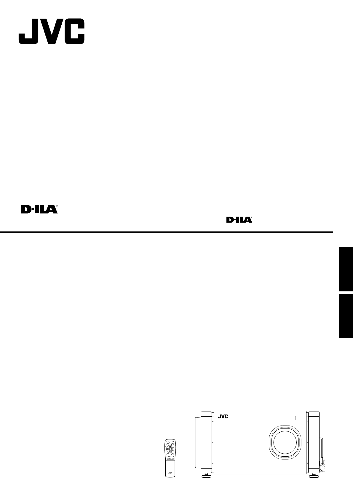
SUPER PROJECTOR
MANUEL D’INSTRUCTIONS : SUPER PROJECTEUR
DLA-M5000LE
INSTRUCTIONS
DLA-M5000SCE
QUICK
ALIGN.
OPERATE
AV HIDE
PRESET
PAGE BACK
LOCK UNLOCK
M
E
LENS
N
U
/
E
N
T
E
R
RGB/COMPUTER
AV
UT
+
SHIFT ZOOM FOCUS
DW
–
LENS
ENGLISHFRANÇAIS
RM-M4100G REMOTE CONTROL UNIT
LCT0979-002B
Page 2

Page 3
Thank you for purchasing this projector. Before using it, read and follow all instructions carefully to take full
advantage of the projector’s capabilities.
SAFETY PRECAUTIONS
IMPORTANT INFORMATION
WARNING :
TO PREVENT FIRE OR SHOCK HAZARDS, DO
NOT EXPOSE THIS APPLIANCE TO RAIN OR
MOISTURE.
WARNING :
THIS APPARATUS MUST BE EARTHED.
CAUTION :
To reduce the risk of electric shock, do not remove cover.
Refer servicing to qualified service personnel.
MACHINE NOISE INFORMATION
(Germany only)
Changes Machine Noise Information Ordinance 3.
GSGV, January 18, 1991: The sound pressure
level at the operator position is equal or less than
70 dB(A) according to ISO 7779.
About burning-in of the D-ILA device
Do not allow the same still picture to be projected for a long
time or an abnormally bright video picture to be projected.
Do not project video images with high-intensity or highcontrast on a screen. The video image could be burned in to
the D-ILA device.
Use special care when projecting video games or computer
program images. There is no problem with ordinary
video-cassette playback images.
WARNING
This is a Class A product. In a domestic environment
this product may cause radio interference in which
case the user may be required to take adequate
measures.
IMPORTANT SAFEGUARDS
Electrical energy can perform many useful functions. This
unit has been engineered and manufactured to assure your
personal safety. But IMPROPER USE CAN RESULT IN
POTENTIAL ELECTRICAL SHOCK OR FIRE HAZARD. In
order not to defeat the safeguards incorporated into this
product, observe the following basic rules for its installation,
use and service. Please read these “Important Safeguards”
carefully before use.
– All the safety and operating instructions should be read
before the product is operated.
– The safety and operating instructions should be retained
for future reference.
– All warnings on the product and in the operating
instructions should be adhered to.
– All operating instructions should be followed.
– Unplug this product from the wall outlet before cleaning.
Do not use liquid cleaners or aerosol cleaners. Use a
damp cloth for cleaning.
– Do not use attachments not recommended by the
product manufacturer as they may be hazardous.
– Do not use this product near water. Do not use
immediately after moving from a low temperature to high
temperature, as this causes condensation, which may
result in fire, electric shock, or other hazards.
– Do not place this product on an unstable
cart, stand, or table. The product may
fall, causing serious injury to a child or
adult, and serious damage to the
product. The product should be mounted
according to the manufacturer’s
instructions, and should use a mount recommended by
the manufacturer.
– When the product is used on a cart, care should be taken
to avoid quick stops, excessive force, and uneven
surfaces which may cause the product and cart to
overturn, damaging equipment or causing possible injury
to the operator.
– Slots and openings in the cabinet are provided for
ventilation. These ensure reliable operation of the
product and protect it from overheating. These openings
must not be blocked or covered. (The openings should
never be blocked by placing the product on bed, sofa,
rug, or similar surface. It should not be placed in a built-in
installation such as a bookcase or rack unless proper
ventilation is provided and the manufacturer’s
instructions have been adhered to.)
For proper ventilation, separate the product from other
equipment, which may prevent ventilation and keep /
distance more than 60 cm.
ENGLISHDEUTSHFRANÇAISITALIANOESPAÑOL
1
Page 4

– This product should be operated only with the type of
power source indicated on the label. If you are not sure
of the type of power supply to your home, consult your
product dealer or local power company.
– This product is equipped with a three-wire plug. This
plug will fit only into a grounded power outlet. If you are
unable to insert the plug into the outlet, contact your
electrician to install the proper outlet. Do not defeat the
safety purpose of the grounded plug.
– Power-supply cords should be routed so that they are not
likely to be walked on or pinched by items placed upon or
against them. Pay particular attention to cords at doors,
plugs, receptacles, and the point where they exit from the
product.
– For added protection of this product during a lightning
storm, or when it is left unattended and unused for long
periods of time, unplug it from the wall outlet and
disconnect the cable system. This will prevent damage
to the product due to lightning and power line surges.
– Do not overload wall outlets, extension cords, or
convenience receptacles on other equipment as this can
result in a risk of fire or electric shock.
– Never push objects of any kind into this product through
openings as they may touch dangerous voltage points or
short out parts that could result in a fire or electric shock.
Never spill liquid of any kind on the product.
– Do not attempt to service this product yourself as
opening or removing covers may expose you to
dangerous voltages and other hazards. Refer all service
to qualified service personnel.
– Unplug this product from the wall outlet and refer service
to qualified service personnel under the following
conditions:
a) When the power supply cord or plug is damaged.
b) If liquid has been spilled, or objects have fallen on the
product.
c) If the product has been exposed to rain or water.
d) If the product does not operate normally by following
the operating instructions. Adjust only those controls
that are covered by the Operation Manual, as an
improper adjustment of controls may result in damage
and will often require extensive work by a qualified
technician to restore the product to normal operation.
e) If the product has been dropped or damaged in any
way.
f ) When the product exhibits a distinct change in
performance – this indicates a need for service.
– When replacement parts are required, be sure the
service technician has used replacement parts specified
by the manufacturer or with same characteristics as the
original part. Unauthorized substitutions may result in
fire, electric shock, or other hazards.
– Upon completion of any service or repairs to this product,
ask the service technician to perform safety checks to
determine that the product is in proper operating
condition.
– The product should be placed more than one foot away
from heat sources such as radiators, heat registers,
stoves, and other products (including amplifiers) that
produce heat.
– When connecting other products such as VCR’s, and
personal computers, you should turn off the power of this
product for protection against electric shock.
– Do not place combustibles behind the cooling fan. For
example, cloth, paper, matches, aerosol cans or gas
lighters that present special hazards when over heated.
– Do not look into the projection lens while the illumination
lamp is turned on. Exposure of your eyes to the strong
light can result in impaired eyesight.
– Do not look into the inside of this unit through vents
(ventilation holes), etc. Do not look at the illumination
lamp directly by opening the cabinet while the
illumination lamp is turned on. The illumination lamp also
contains ultraviolet rays and the light is so powerful that
your eyesight can be impaired.
– Xenon gas is enclosed with high pressure inside the light-
source lamp (lamp unit) of this projector. If you drop or
impart a shock to the lamp, or discard it as is, there is the
possibility of explosion, leading to personal injury. Use
special care when handling the lamp. For any unclear
points, consult your product dealer.
– Use only the accessory cord designed for this product to
prevent shock.
The power supply voltage rating of this product is
AC 200 V - AC 240 V, the power cord attached conforms
to the following power supply voltage. Use only the
power cord designated by our dealer to ensure Safety
and EMC.
When it is used by other power supply voltage, power
cable must be changed.
Consult your product dealer.
* DO NOT allow any unqualified person to
install the unit.
Be sure to ask your dealer to install the unit (eg.
attaching it to the ceilling) since special technical
knowledge and skills are required for installation.
If installation is performed by an unqualified person, it
may cause personal injury or electrical shock.
2
Page 5
POWER CONNECTION
(United Kingdom only)
WARNING
Do not cut off the main plug from this equipment.
If the plug fitted is not suitable for the power points in your
home or the cable is too short to reach a power point, then
obtain an appropriate safety approved extension lead or
adapter or consult your dealer.
If nonetheless the mains plug is cut off, remove the fuse and
dispose of the plug immediately, to avoid a possible shock
hazard by inadvertent connection to the main supply.
If a new main plug has to be fitted, then follow the instruction
given below:
WARNING:
THIS APPARATUS MUST BE EARTHED.
IMPORTANT:
The wires in the mains lead on this product are coloured in
accordance with the following cord:
Green-and-yellow: Earth
Blue: Neutral
Brown: Live
The wire which is coloured green-and-yellow must be
connected to the terminal which is marked ˙ with the letter E
or the safety earth or coloured green or green-and-yellow.
The wire which is coloured blue must be connected to the
terminal which is marked with the letter N or coloured black.
The wire which is coloured brown must be connected to the
terminal which is marked with the letter L or coloured red.
When replacing the fuse, be sure to use only a correctly
rated approved type, re-fit the fuse cover.
IF IN DOUBT —— CONSULT A COMPETENT
ELECTRICIAN.
As these colours may not correspond with the coloured
making identifying the terminals in your plug, proceed as
follows:
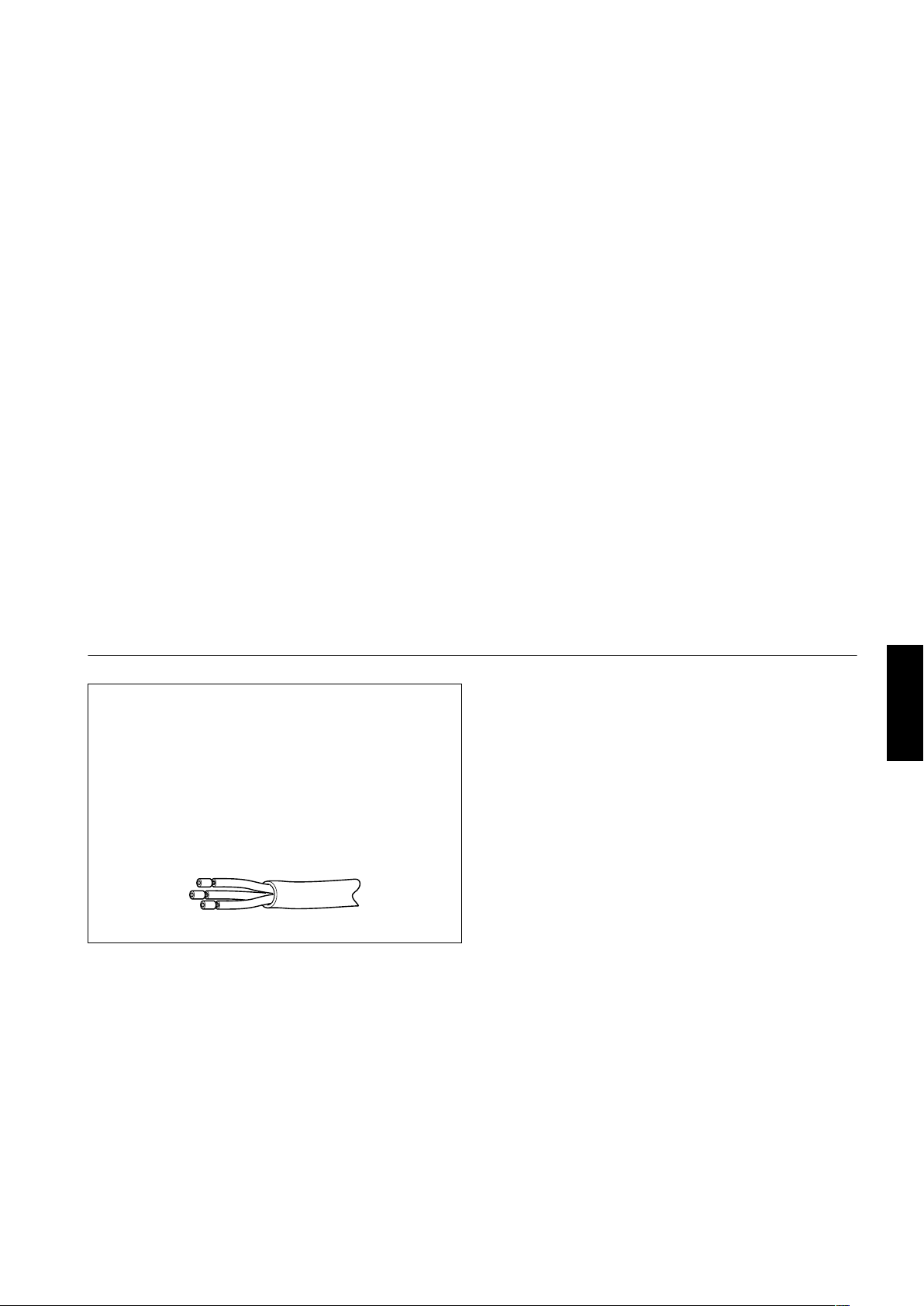
Information on the power cord plug
The power cord of this projector does not have a wall
outlet plug attached. We recommend you to select and
attach a plug which matches your wall outlet.
Use a plug rated 250V/20A.
The wires ends of the power cord are covered for
protection.
Remove the covers before attaching the plug to the
power cord.
ENGLISHDEUTSHFRANÇAISITALIANOESPAÑOL
3
Page 6
Contents
SAFETY PRECAUTIONS ................. 1
Contents........................................... 4
Accessories ..................................... 4
Controls and Features .................... 5
Front Side / Top Surface / Right Side .....................5
Left-hand side / Back Side ......................................6
Control Panel ..........................................................7
Connector Panel .....................................................9
Remote Control Unit..............................................10
MENU/ENTER (Menu Operation) Button..............12
Installing Batteries.................................................12
Installing the Projector.................. 13
Precautions for Installation....................................13
Lens Shift Function ...............................................15
Projection Distances and Screen Sizes ................17
Connecting to Various Devices.... 18
Signals that Can Be Input to the Projector............18
Examples of System Configuration.......................19
Connecting to Computer Devices .........................20
Connecting to Devices which Control the
Projector................................................................21
Connecting the Power Cord (Supplied).................22
When Turning On the Devices Connected to the
Projector................................................................23
Basic Operations........................... 24
1. Turning on the Power........................................24
2. Select the video input to be projected...............25
3. Adjust the screen size .......................................25
4. Adjust focus.......................................................26
For Operating Other Functions .............................26
Operating the Setting Menu.......... 29
Making Basic Settings...........................................29
Operating the Main Menu ..............30
Configuration the Main Menu (AV Input) .............. 30
Configuration of the Main Menu
(Computer-related input) ...................................... 31
Operating the Main Menu
(Basic Operation of the Main Menu)..................... 32
Changing the Color System ................................. 33
Changing the Language Display .......................... 34
Adjusting the Pixel Clock...................................... 35
Adjusting the Screen Position .............................. 36
Adjusting Picture Quality ...................................... 37
Setting and Adjusting Other Functions
(OPTIONS)........................................................... 40
Changing (Setting) the Source ............................. 43
Setting Up Channels ............................................ 46
Setting Up Channels (LINE setup) ....................... 47
Setting Up Channels (SOURCE setup)................ 48
Setting Up Channels (SW No setup).................... 50
Changing Channels (CH Change)........................ 51
Setting Up (or Changing) User Sources............... 53
Setting Up (or Changing) the Display Size........... 56
Filter Maintenance and Light-Source
Lamp Replacement........................ 58
Cleaning and Replacing the Filter ........................ 58
About Light-Source Lamp Replacement .............. 59
Troubleshooting............................. 60
Specifications................................. 63
Outside dimensions.............................................. 65
Pin assignment (Specifications for terminals) ...... 66
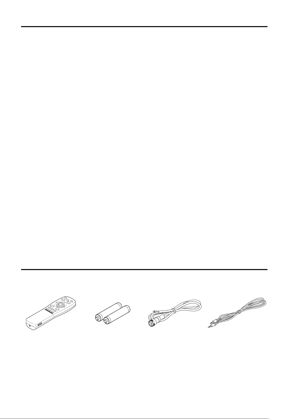
Accessories
he following accessories are included with this projector. Check for them; if any item is missing, please
contact your dealer.
Remote control unit
(RM-M4000G)
4
AA/R6-size dry cell battery (×2)
(for checking operation)
Power code
[approx. 3.35 m]
Remote control cable
[approx. 15 m]
Page 7
Controls and Features
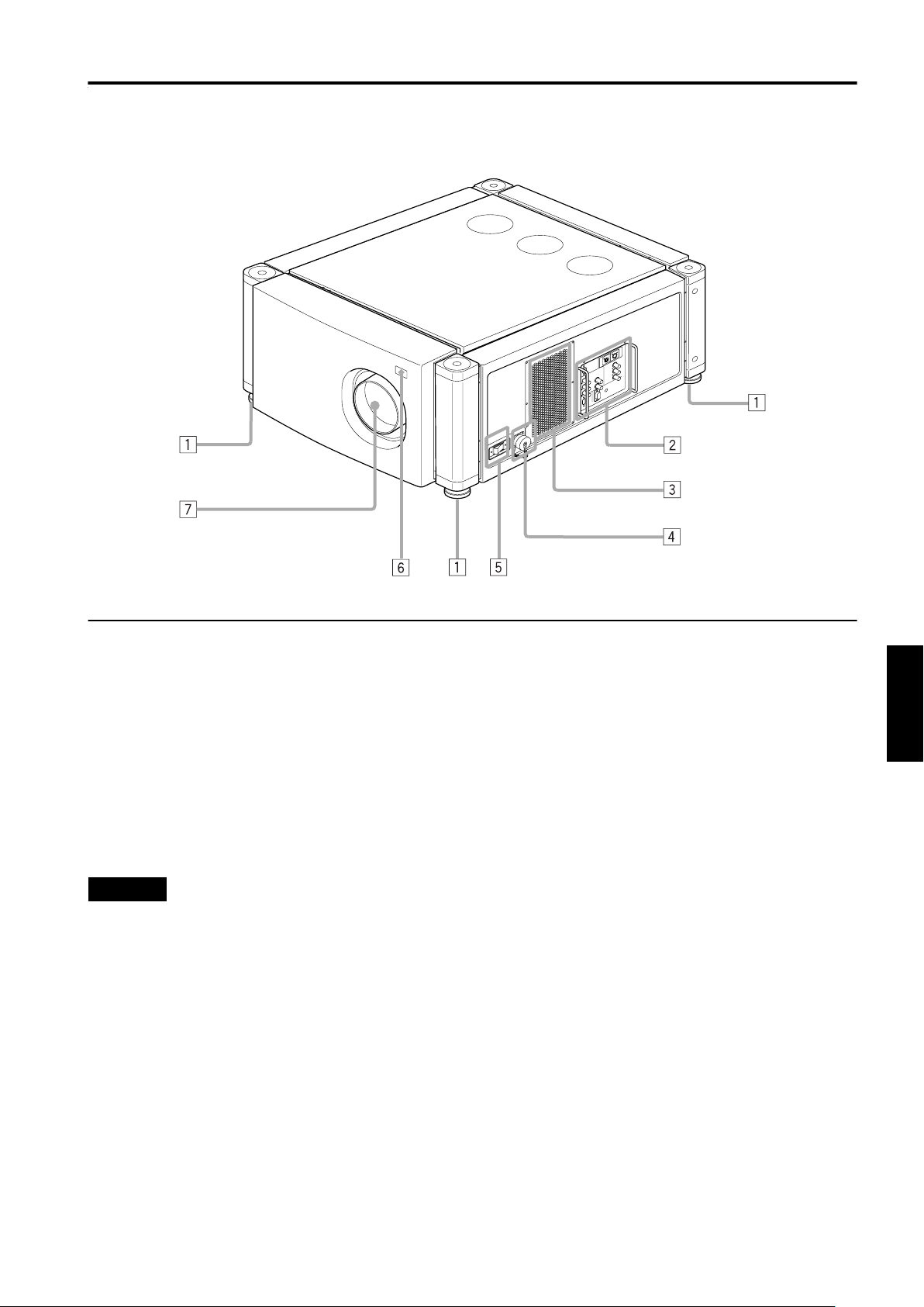
Front Side / Top Surface / Right Side
1 Adjustable foot
It is set at the shortest position when shipped from the
factory. Turn the foot to make the projector level.
Adjustment can be made in the range of ±4° from the
vertical and ±5° from the horizontal.
2 Connector panel
For details, refer to “Connector Panel” on page 9.
3 Air intake area (filter)
Air is taken in through this area to cool the light-source
lamp. If this area is blocked or if something that obstructs
taking in or exhausting air is placed around the projector,
heat may build up inside and could cause a fire. For
details, refer to “Precautions for Installation” on page 13.
CAUTIONS
• Be careful as paper, cloth or soft cushion could be drawn in
if placed nearby. Do not block the intake area, or heat may
build up and could cause a fire.
• Clean the filter periodically. For details, refer to “Cleaning
and Replacing the Filter” on page 58.
Deposition of dirt on the filter works to reduce the cooling
effect, causing heat to build up inside, which could cause a
fire or malfunction.
4 AC IN (power input) terminal
This is the power input terminal where the supplied power
cord is connected. For details, refer to page 22.
5 MAIN POWER switch
This is the main power switch. When it is turned on, the
projector goes into stand-by state, and the STAND BY
indicator on the control panel comes on.
ON [ ❘❘❘❘ ]: The main power turns on.
OFF [{{{{]: The main power turns off.
6 Remote sensor
When operating with the remote control, aim it toward this
sensor. An additional remote sensor is provided on the
back of the projector. The effective operating distance of
the remote control is 10 m from each of the sensors. The
effective operating range of angles is 50° left and right,
and 15° up and down.
7 Lens mount
Attach a projection lens separately sold to this mount.
GL-M4023SZ 3 : 1~7 : 1 zoom lens
GL-M4015S 1.5 : 1 fixed-focus lens
For information on attaching the lens, consult the dealer
or service center who performed the installation and
adjustments of your projector.
ENGLISHDEUTSHFRANÇAISITALIANOESPAÑOL
5
Page 8
Controls and Features
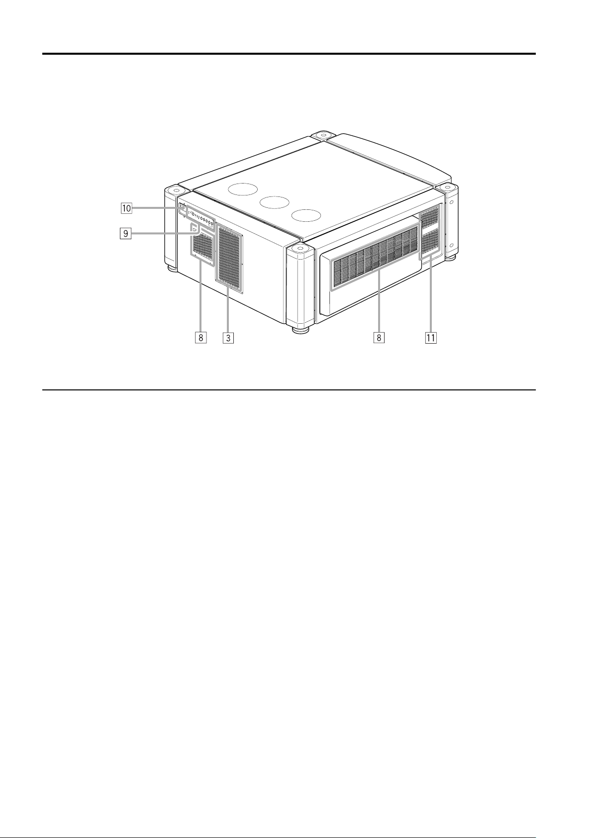
Left-hand side / Back Side
8 Exhaust vents
Vents for cooling fans through which warm air comes out.
9 Control panel
For details, refer to “Control Panel” on page 7 and 8.
p Remote sensor
When operating with the remote control, aim it toward this
sensor. An additional remote sensor is provided on the
front of the projector. The effective operating distance of
the remote control is 10 m from each of the sensors. The
effective operating range of angles is 50° left and right,
and 15° up and down.
q Exhaust vent (for the light-source lamp power supply)
Warm air comes out of this vent from the cooling fan for
the light-source lamp power supply. This fan continues
running as long as the MAIN POWER switch is on.
6
Page 9

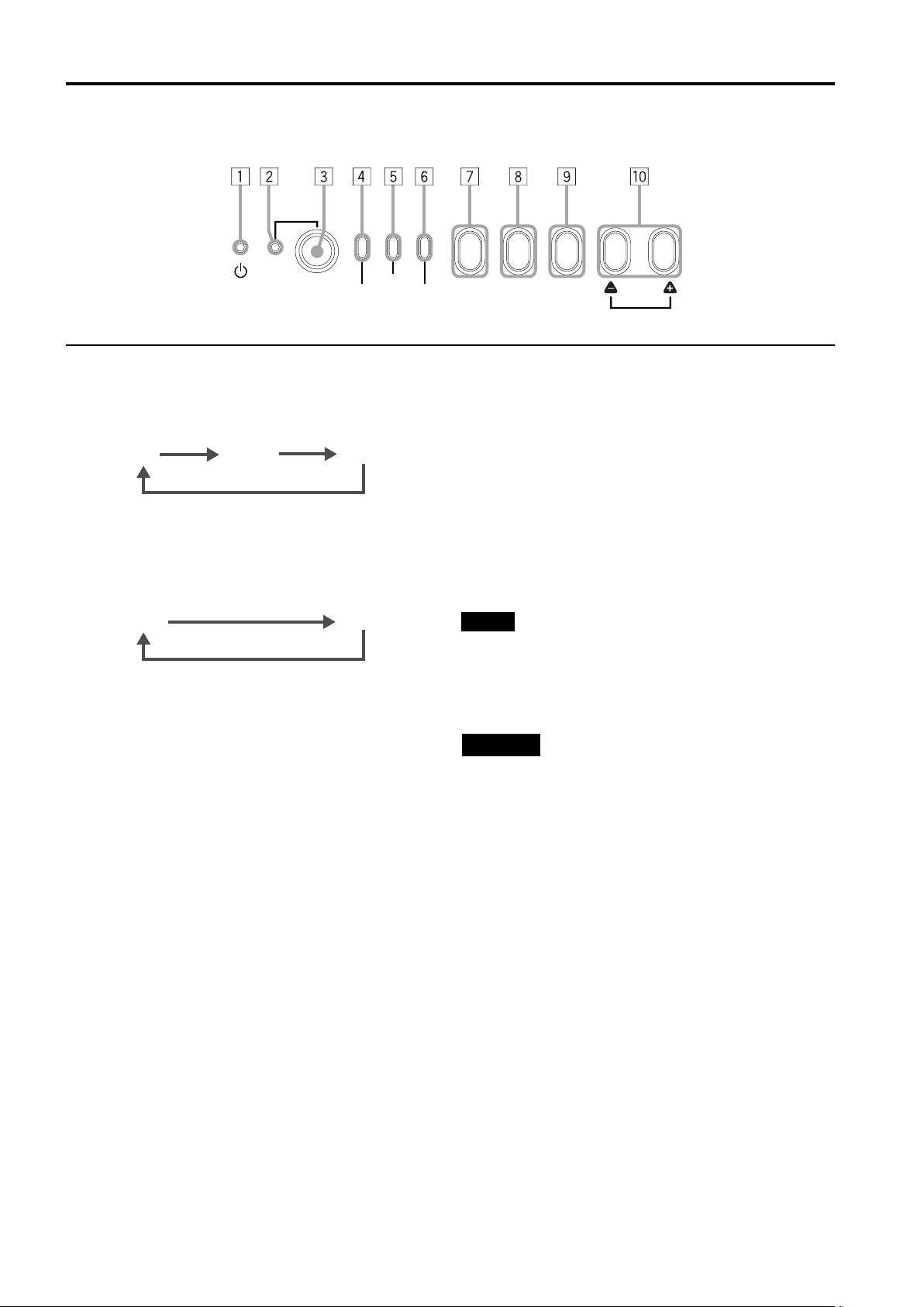
Control Panel
Controls and Features
STAND BY
1 STAND BY Indicator
ON: When in stand-by mode.
Blinking: When in cool-down mode.
CAUTIONS
• The cool-down mode continues for about 20 seconds,
during which projection cannot–be started again. After the
cooling-down period, the projector goes into stand-by
mode, but the cooling fans will continue to run for about 10
minutes more before they stop (except the cooling fan for
the light-source lamp power supply which continues
running as long as the MAIN POWER switch is on).
• The purpose of the cool-down mode is to prevent inner
parts from being deformed or broken by heat from the
heated lamp as well as to prolong the life of the lamp. Do
not turn off the main power switch while in the cool-down
mode. Also, do not block any of exhaust openings while in
cool-down mode.
2 OPERATE indicator
ON: When the projector is in operation (projecting)
3 OPERATE button
When the projector is in the stand-by mode, press this
button for one or more seconds, and the main power
switch is turned on, causing the OPERATE indicator to
light. Press it again, and the projector goes into the cooldown mode, then stand-by mode.
Memo
While in the cool-down mode:
If you press the OPERATE button, the projector is not tuned
on.
4 Lamp indicator
ON: After the light-source lamp has been used for
more than approx. 900 hours.
Blinking:
5 TEMP indicator
ON: The temperature inside the projector has abnormally
Replace the lamp. (Ask the dealer where you
purchased your projector to replace the lamp.)
risen.
OPERATE
LAMP
TEMP
EMERGENCY
AV RGB
6 EMERGENCY indicator
Blinking:Something abnormal has occurred with the
Memo
About the emergency mode:
The emergency mode is shown when the following
anomalies have occurred with the projector (the
EMERGENCY indicator blinks). In the emergency mode,
projection is automatically interrupted and the cooling fans
operate for about 10 minutes (except the cooling fan for the
light-source lamp power supply which continues running as
long as the MAIN POWER switch is on).
• When the light-source lamp has suddenly gone off.
• When the fans have stopped.
• When the temperature inside has risen abnormally
high.
CAUTION
• When an emergency mode is shown:
After the cooling fans (except the one for the light-source
lamp power supply) have stopped, turn off the main power
switch and unplug the power cord from the wall outlet.
Check that the filter covers are correctly installed. Then,
plug in the power cord again and try operating the
projector.
If it goes into an emergency mode again, after the cooling
fans have stopped, turn off the main power switch, unplug
the power cord, and call your dealer for repair.
SETTING
projector.
QUICK
ALIGN.
ENGLISHDEUTSHFRANÇAISITALIANOESPAÑOL
Note
• While the TEMP indicator is on (during abnormal
temperature), the power is automatically cut off, and an
emergency mode is shown (with the EMERGENCY
indicator blinking).
7
Page 10
Controls and Features
Control Panel (Cont.)
STAND BY
OPERATE
LAMP
TEMP
7 AV button
Use this button to select a device such as a video deck
connected to the EXT. IN terminal of the projector. Each
time you press the button, the device selected changes as
follows:
Y/C*
VIDEO*
YPBPR
* Y/C and VIDEO can be used only when a video board
separately sold has been installed.
8 RGB button
Use this button to select a device connected to the RGB 1 or -2 terminals. Each time you press the button, the
selection changes as follows:
RGB 1
RGB 2
9 SETTING button
Use this button to call up the setting menu. For details,
refer to “Making Basic Settings” on page 29.
EMERGENCY
AV RGB
SETTING
QUICK
ALIGN.
p QUICK ALIGN. (Quick Alignment) button
While a menu screen is shown, use this button to adjust
the values for the item selected. When no menu is shown,
the quick alignment function works.
When a menu is shown
++++ button: The value for the selected item increases.
---- button: The value for the selected item decreases.
When no menu is shown
Press the ++++ button and ---- button at the same time:
“QUICK-ALIGNMENT” (Quick-Alignment) is displayed on
the screen and the quick alignment function works
(TRACKING, PHASE, H. POS. and V. POS. are
automatically adjusted). When the adjustment is finished,
the display goes off automatically.
Memo
The quick alignment function:
• Works for computer input (RGB- 1 and - 2 input terminals)
signals.
• Does not work for video input (EXT. IN input terminal)
signals.
CAUTION
• Automatic adjustment with the quick alignment function
should be done on a bright still-picture screen. This function
may not work correctly on a dark screen or motion-picture
screen. If adjustment with this function is not satisfactory,
adjust TRACKING, PHASE, H. POS. and V. POS. manually
(see pages 29, 35 and 36).
8
Page 11
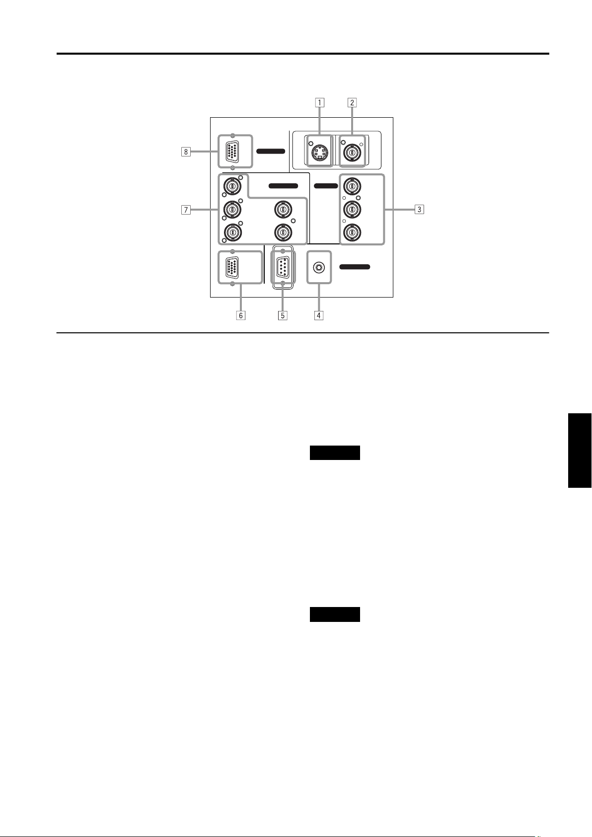
Connector Panel
RGB
Controls and Features
Y/C VIDEO
RGB IN-1
RGB IN-2
R
GH/CS
BV PR/R-Y
RGB OUT
1 Y/C (S video) input terminal (Mini DIN 4 pin)
Connect this terminal to the S video output terminal of a
video deck, etc.
* This terminal can be used if a video board (PK-G1101D)
sold separately has been installed. The terminal was not
provided when the projector was shipped from the
factory.
2 VIDEO (composite video) input terminal (BNC)
Connect this terminal to the composite video output
terminal of a video deck, etc.
* This terminal can be used if a video board (PK-G1101D)
sold separately has been installed. The terminal was not
provided when the projector was shipped from the
factory.
3 Y, PB/B-Y, PR/R-Y input terminals (BNC)
These are input terminals for component (Y, B-Y, R-Y)
signals or DTV-format (Y, P
, PR) signals.
B
Device with component signal output terminals, such as
for NTSC and DTV-format, can be connected.
* For details about DTV-format signals (480i, 480p, 720p,
1080i) compatible with this unit, refer to 65.
4 REMOTE terminal (mini jack)
This terminal is used to directly connect the remote
control to the projector. Use the remote control cable
supplied.
An infrared remote control extension unit can also be
connected to the jack.
5 RS-232C terminal (D-sub 9 pin)
This is a RS-232C interface-specified terminal. This
projector can be controlled by a computer connected
externally.
6 RGB OUT (RGB output) terminal (D-sub 3-row 15 pin)
The computer input signal projected on the screen is
output.
A display unit can be used by connecting it to this
terminal.
EXT. IN
REMOTE
RS-232C
CONTROL
Y
P
B/B-Y
7 RGB IN (RGB input) -2 terminal (BNC)
These are input terminals for analog RGB signals, vertical
sync (V) signals, and horizontal sync (H) signals /
). Devices which have analog RGB
composite signals (C
S
signal output terminals can be connected.
* Input of external sync signals is automatically
detected.
Detection of H/V signals or CS signals causes automatic
switch to external sync. The priority order is H/V > C
CAUTION
• When computer-related signals are input, the uppermost
edge of the screen may appear bowing if the sync signal
input is composite sync (CS) or G on sync signal. In that
case, use separate sync signals for vertical sync (V) and
horizontal sync (H).
8 RGB IN (RGB input) -1 terminal (D-sub 3- row 15 pin)
This is an input terminal (PC) dedicated for computer
signals (RGB video signals and sync signals).
Connect the display output terminal of the computer to
this terminal. When a Macintosh or PC-9801/9802 series
computer is to be connected, use a suitable conversion
adapter separately available.
CAUTION
• When computer-related signals are input, the uppermost
edge of the screen may appear bowing if the sync signal
) or G on sync signal. In that
input is composite sync (C
S
case, use separate sync signals for vertical sync (V) and
horizontal sync (H).
.
S
ENGLISHDEUTSHFRANÇAISITALIANOESPAÑOL
9
Page 12
Controls and Features
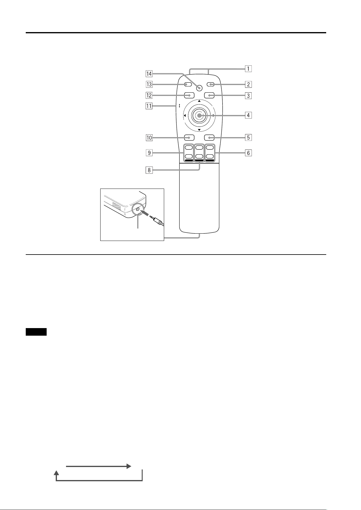
Remote Control Unit
LOCK UNLOCK
LENS
QUICK
ALIGN.
PRESET
OPERATE
AV HIDE
PAGE BACK
M
E
N
U
/
E
N
T
E
R
RGB/COMPUTER
AV
7
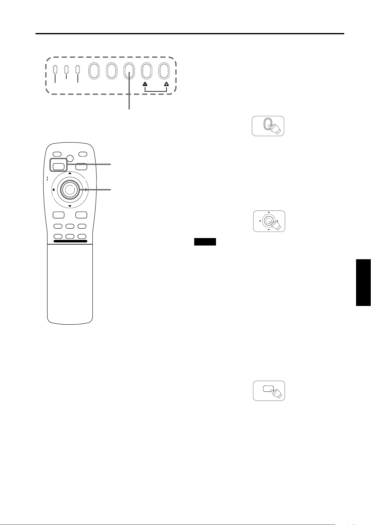
1 Remote control’s signal transmitter
2 OPERATE button
To turn on or off the power, press this button for one or
more seconds.
* About 30 seconds after the power has turned on, video
image will appear on the screen.
3 PAGE BACK button
While no menu is displayed, pressing this button causes a
direct channel to be displayed.
Memo
Direct channel display:
A direct channel display allows you to switch between
channels which have lines and sources registered. For
details, refer to “Switching channels using a DIRECT
CHANNEL” (page 51).
4 MENU/ENTER button
Use this button to display the main menu, or while the
main menu is displayed, use the button to select an item
to adjust or make adjustment. While the main menu is
displayed, pressing MENU/ENTER displays a details
setting (submenu) if the selected item has a details
setting.
For how to operate the buttons, see page 12.
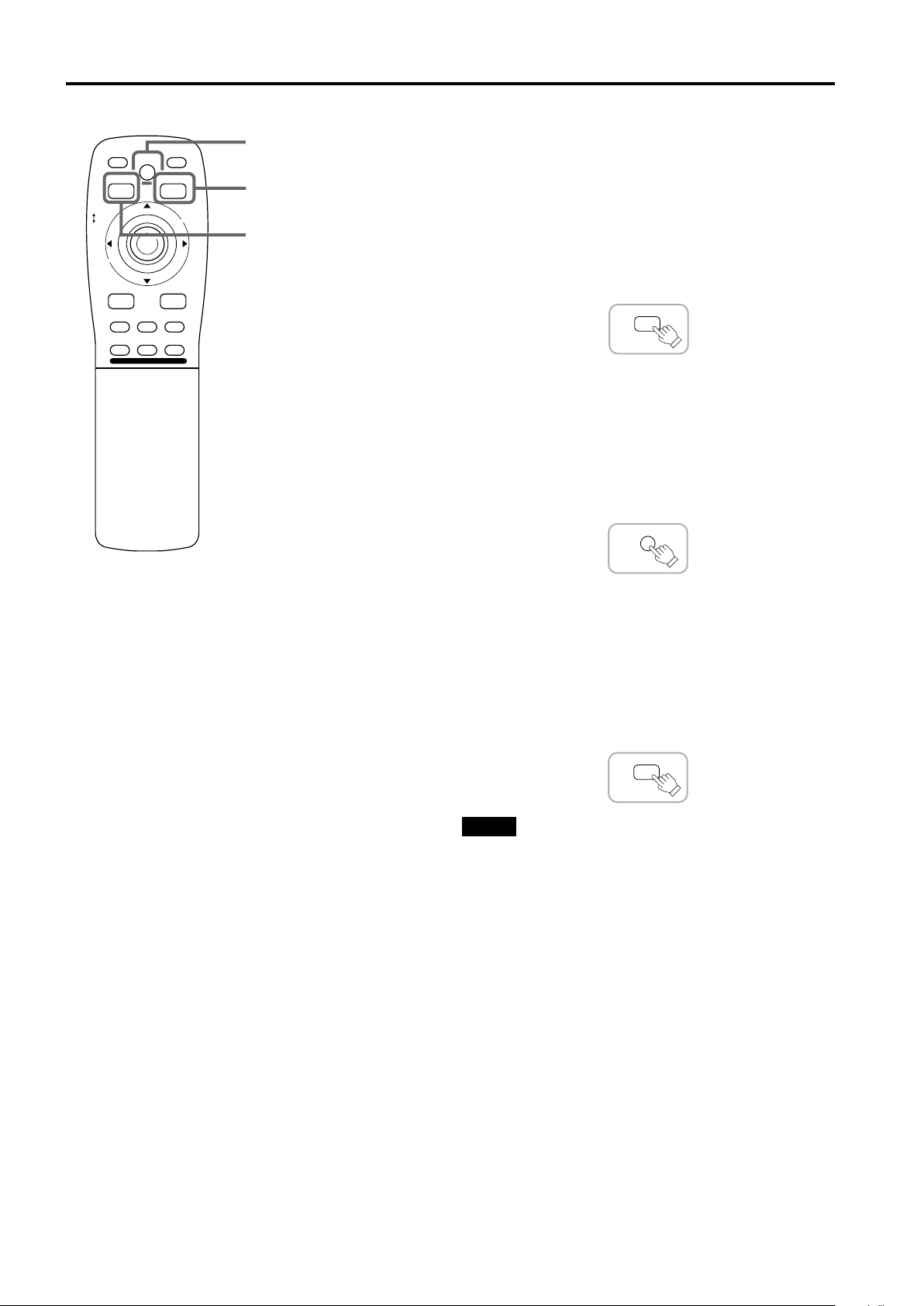
5 RGB/COMPUTER button
Use this button to select the devices connected to the
projector’s RGB IN (RGB input) -1 and -2 input terminals.
Each time you press the button, the selection changes as
follows:
RGB 1
RGB 2
UT
SHIFT ZOOM FOCUS
DW
LENS
+
–
6 FOCUS (+/–) button
Use these buttons to adjust the focus of the projected
picture.
+: The focus point becomes more distant.
–: The focus point becomes nearer.
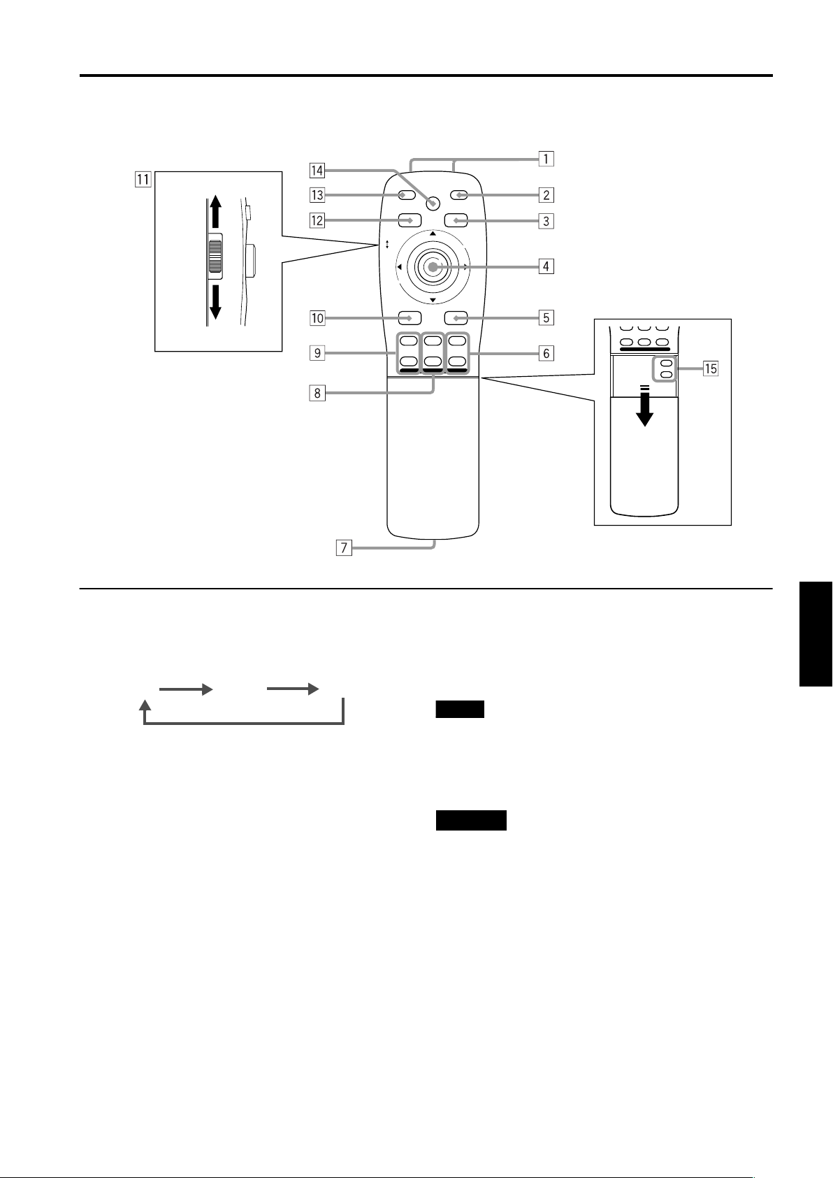
7 REMOTE terminal
Use a remote control cable to connect between the
projector and the remote control. For details, refer to
“Connecting to Devices which Control the Projector” on
page 21.
8 ZOOM (T/W) button
Use these buttons to increase or decrease the screen
size. (They can only be used when a zoom lens is used.)
T: The screen size decreases.
W: The screen size increases.
9 SHIFT (U/D) button
Use these buttons to adjust the height of the projection
screen when projectors are used in a stack configuration.
U: Moves the screen upwards.
D: Moves the screen downwards.
10
Page 13
Remote Control Unit (Cont.)
QUICK
ALIGN.
AV HIDE
PRESET
LOCK UNLOCK
LENS
AV
UT
SHIFT ZOOM FOCUS
DW
RGB/COMPUTER
LENS
OPERATE
PAGE BACK
M
E
N
U
/
E
N
+
–
Controls and Features
QUICK
ALIGN.
OPERATE
AV HIDE
PRESET
PAGE BACK
LOCK UNLOCK
T
E
R
LENS
AV
UT
SHIFT ZOOM FOCUS
DW
LENS
M
E
N
U
/
E
N
RGB/COMPUTER
+
–
+
VOLUME
–
T
E
R
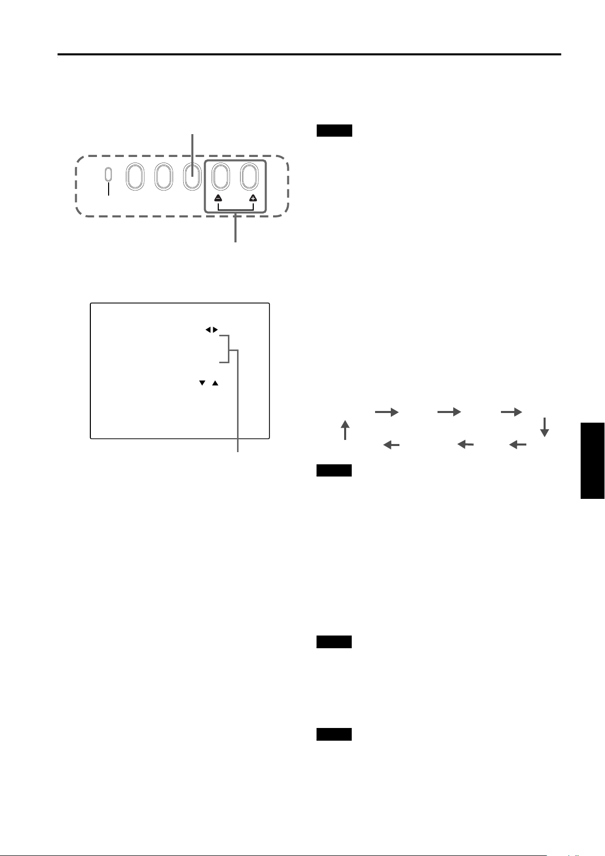
p AV button
Use this button to select the devices such as a video
connected to the projector’s AV IN (EXT. input) terminal.
Each time you press the button, the selection changes as
follows:
Y/C*
VIDEO*
YPBPR
* Y/C and VIDEO can be used only when a video board
separately sold has been installed.
q LENS LOCK j UNLOCK switch
With this switch set at the LOCK position, adjustment
operations (focus, zoom or shift) with the remote control
are disabled, preventing adjustment contents from being
inadvertently changed while the remote control is being
used. When adjustment is needed, set the switch to the
UNLOCK position.
w PRESET button
While making adjustment on the main or setting menu,
use this button to reset the setting of the selected item to
the factory-set value. This button works only for numerical
settings and does not work for switching ON to OFF.
e QUICK ALIGN. (Quick Alignment) button
Use this button to automatically adjust TRACKING,
PHASE, H. POS. and V. POS. of the projected video.
During the automatic adjustment, “QUICK-ALIGNMENT”
(Quick-Alignment) appears on the screen, and disappears
after it is finished.
Memo
Quick alignment function:
Does not work for video input (EXT. IN input terminal)
signals.
Works only for computer-related (RGB -1 and -2 input
terminals) signals.
CAUTION
• Automatic adjustment with the quick alignment function
should be done on a bright still-picture screen. This function
may not work correctly on a dark screen or motion-picture
screen. If adjustment with this function is not satisfactory,
adjust TRACKING, PHASE, H. POS. and V. POS. manually
(see pages 29, 35 and 36).
r AV HIDE button
Use this button to turn off the video image temporarily.
Pressing it again makes the video image to resume.
t Not used with this projector
ENGLISHDEUTSHFRANÇAISITALIANOESPAÑOL
11
Page 14
Controls and Features
MENU/ENTER (Menu Operation) Button
The remote control supplied with this projector has only one button to navigate through the menus. Pressing the menu
operation button too strongly may cause an incorrect operation. So, before you use the button in an actual situation, have
some practice to make yourself familiar with using the button.
1 When using the MENU/ENTER button as a menu
operation button:
Press the button down straight when displaying the main
menu. While the main menu is displayed, if the selected
item has a details setting (submenu), pressing the button
will cause the submenu to be displayed.
2 When using the MENU/ENTER button as a cursor
moving button:
Press the button toward one of the 5/∞/2/3 marks.
While the main menu is displayed, use the button to select
an item to adjust or make adjustment.
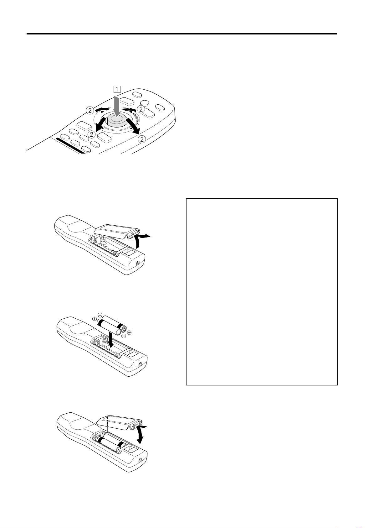
Installing Batteries
Install batteries in the remote control. If the remote control has started to work erratically, replace the
batteries.
Open the back cover.
1
Open the back cover in the direction of the arrow.
Install the batteries.
2
Place the two batteries (AA/R6-size) supplied in the
remote control as illustrated below.
Close the back cover.
3
First fit the claw on the back cover into the case, then
close the back cover in the direction of the arrow.
Precautions for using batteries
If batteries are used incorrectly, they may crack or
leak liquid. This could cause a fire, burn, malfunction,
or staining or damaging the surrounding.
Beware of the following:
• Do not mix new and old batteries.
• Do not mix different types of batteries as they differ in
characteristics.
• Place batteries so they match the polarities indicated: (+)
to (+) and (–) to (–).
• Be sure to put the minus (–) end in first to avoid shortcircuiting.
• Use only designated batteries.
• Remove the batteries if not used for a prolonged period
of time.
• When the batteries are exhausted, replace them
immediately. Otherwise, liquid could leak, or malfunction
could occur due to leaked liquids. If the leaked liquid
contacts the skin, wipe it off with a cloth, otherwise the
skin could become rough.
• Do not put batteries into fire or try to recharge them.
• Batteries run for six months to one year in normal use.
But the batteries supplied are for confirming operation
and may not run that long. When the remote control
starts failing to work properly, replace the batteries with
new ones.
12
Page 15
Installing the Projector
Precautions for Installation
CAUTION
• Since the projector weighs approx. 70 kg (154 lbs.), be sure to use four or more people when lifting or moving it;
otherwise, the projector could possibly drop, causing personal injury and/or damage to the projector.
• Do not install the projector in the following places:
• There is much water, humidity or dust.
• The projector may be subjected to oil smoke or cigarette smoke.
• On a soft surface such as a carpet or cushion.
• The projector may be subjected to direct sunlight.
• Temperature is high or humidity is low.
Allowable operation temperature range: + 5°C to + 40°C
Allowable relative humidity range: 90% or less (no condensation)
Allowable storage temperature range: –5°C to +60°C
■
When installing the projector, observe the followings:
• Do not use the projector placed on its side or upside down.
The projector can not be used by being placed on its side or upside down; Otherwise, it could malfunction.
• Use the projector within the installed angle.
Avoid using the projector inclined ±5° or more right-to-left or left-to-right. This could cause color variation or harm the
lamp life.
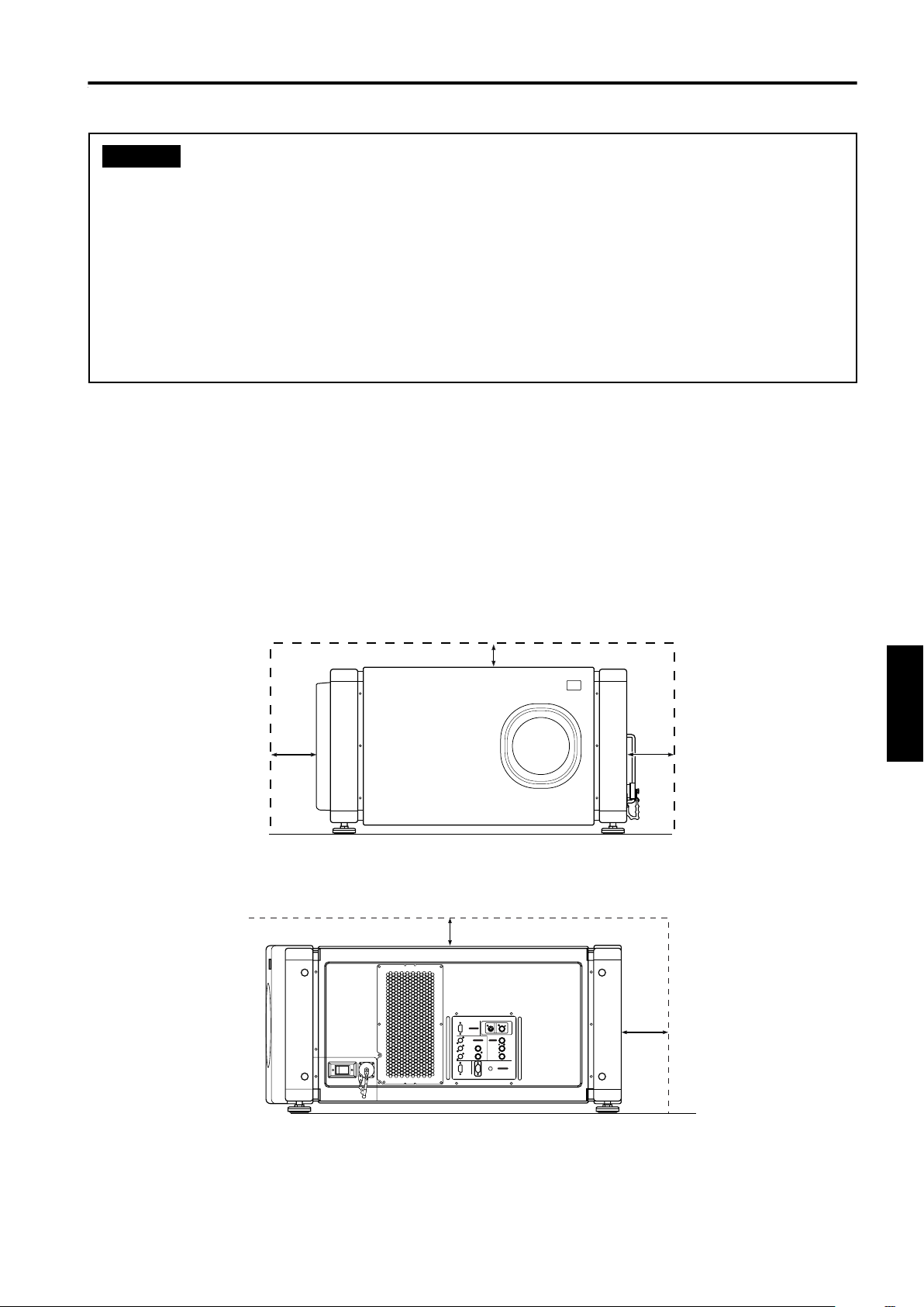
• Do not block the exhaust vents.
Do not use a cover which encloses the projector air-tight or blocks the exhaust vents. Allow sufficient space around the
projector. When the projector is enclosed in a space of the following dimensions, use an air conditioner so the
temperature inside becomes equal to the outside temperature.
Allowable minimum space required
600 mm
305 mm
305 mm
Y/C VIDEO
RGB
RGB IN-1
RGB IN-2
EXT. IN
R
G H/CS
BV PR/R-Y
REMOTE
RGB OUT
RS-232C
600 mm)
Y
B/B-Y
P
CONTROL
600 mm
ENGLISHDEUTSHFRANÇAISITALIANOESPAÑOL
13
Page 16
Installing the Projector
Precautions for Installation (Cont.)
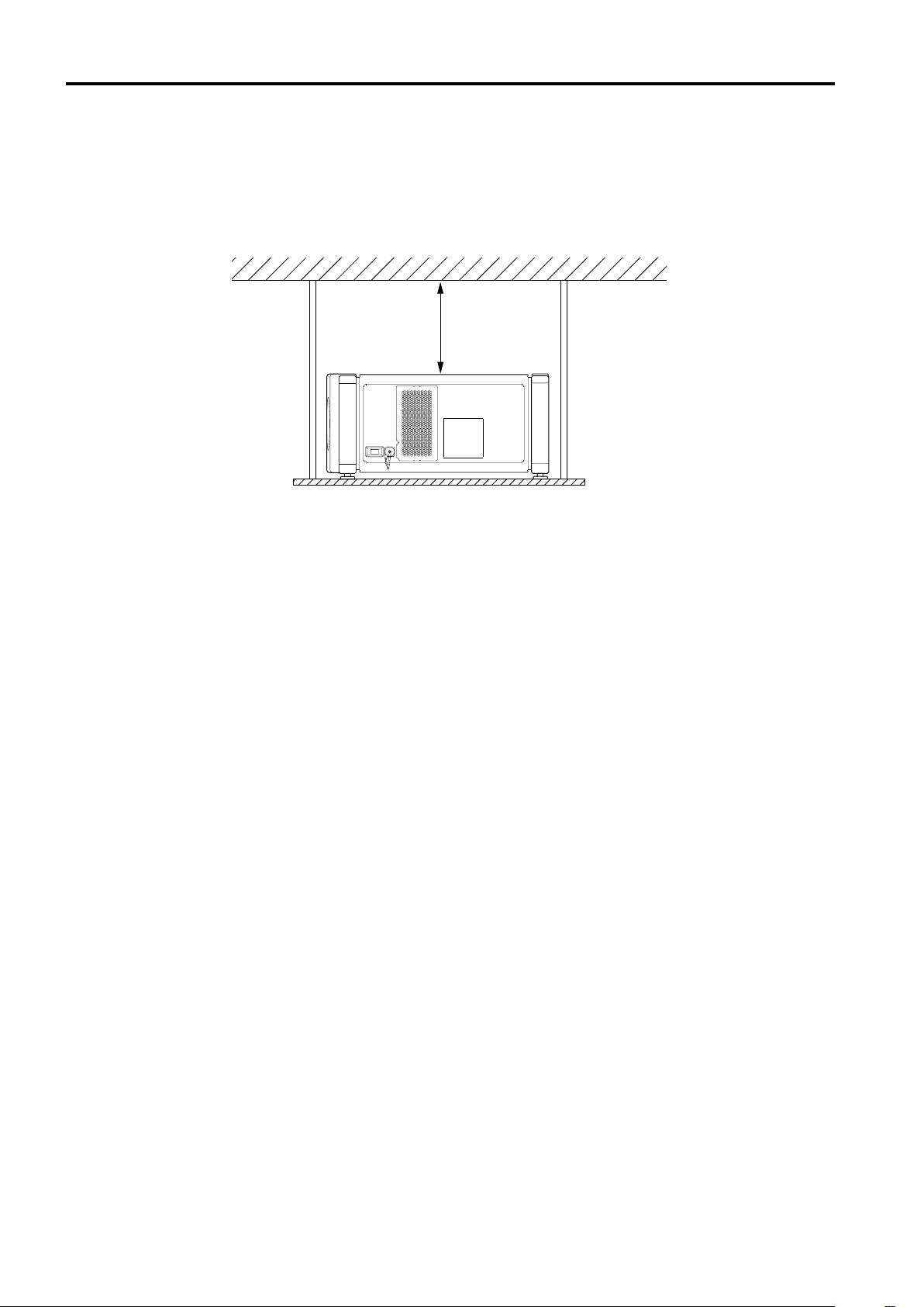
■ Observe the following points when installing the projector by hanging it from the ceiling
• To prevent falling or overturning, it is recommended that the projector be fixed to its stand with bolts.
• When mounting the projector to the ceiling, first install a special shelf and then set the projector on it securely. For safety
and maintenance purposes, a suitable facility is necessary to easily lift and lower the projector from the shelf for
maintenance access.
305 mm
or more
14
Page 17
Lens Shift Function
Screen
Installing the Projector
■■■■ Change of projection screen
according to aspect ratio
Screen with 4 : 3 aspect ratio
Screen with 16 : 9 aspect ratio
90°
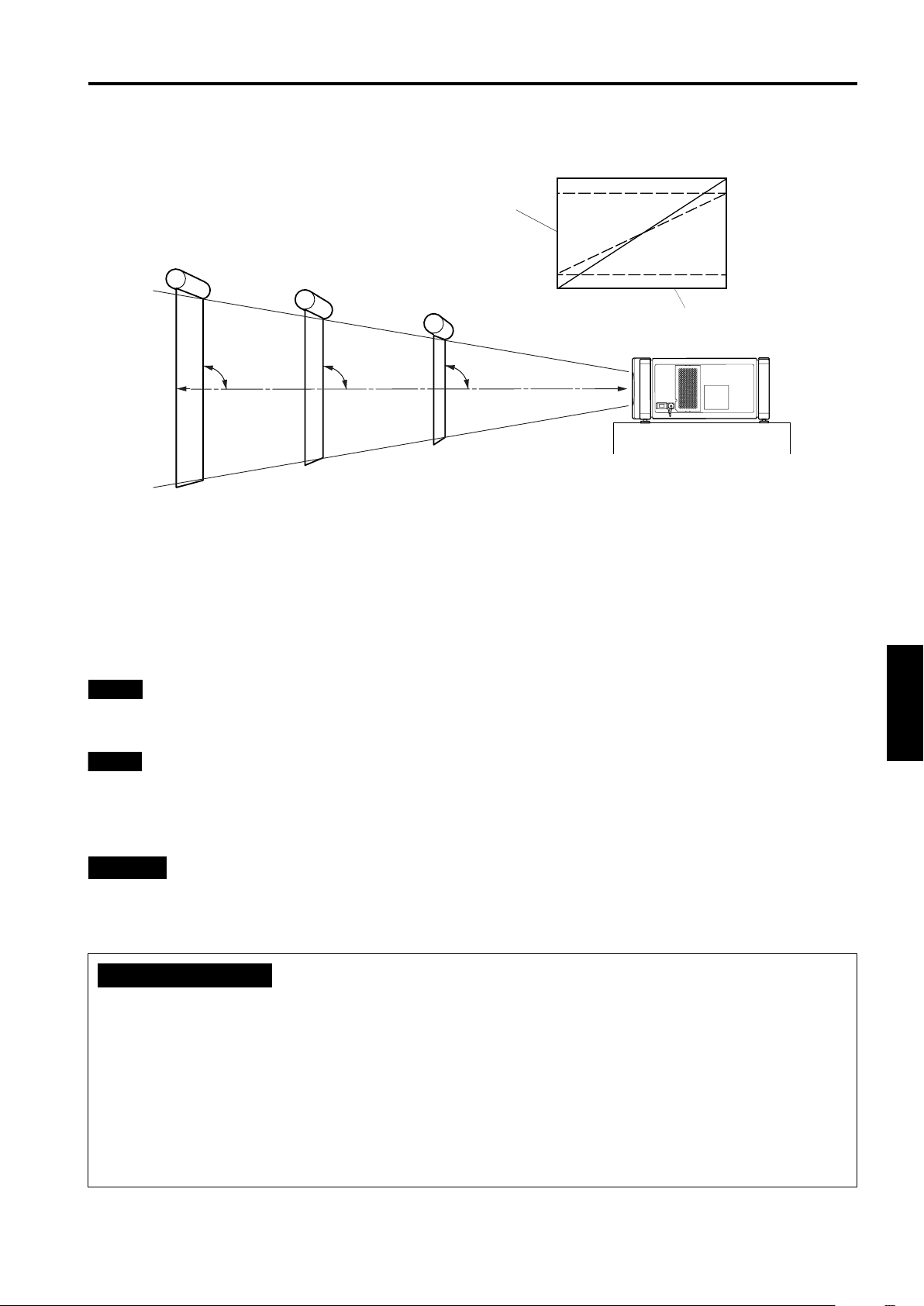
The separately sold lenses used on the projector have a lens shift function. With the lens used, you can adjust the projected
image vertically using the setting menu or the remote control’s SHIFT button U or D.
When using the projectors in a stack configuration (stacked one over another), make adjustment so that the picture of one
projector overlays exactly that of another using the lens shift function.
For detailed adjustment procedures, refer to “Operating the Setting Menu” on page 29 and “Controls and Features” (page 10).
For maximum amount of shift, refer to “Maximum amount of shift” on page 16.
(When the lens needs to be adjusted in horizontal angles, consult your dealer or service center.)
Note
• Some of the lenses (except GL-M4023SZ and GL-M4015S) to be introduced in the future may not feature the lens shift
function.
Memo
Stack configuration:
Up to four projectors can be stacked and used together (stack configuration).
Using two or more projectors together, high image brightness can be attained. This allows you to project sufficiently bright
image in a fairly large auditorium or relatively bright place without using a heavy-duty projector.
90°
Install the projector so the center of the projection
screen is the same height as the center of the lens.
90°
Center line of the lens
ENGLISHDEUTSHFRANÇAISITALIANOESPAÑOL
CAUTION
• To prevent damage to the projector during shipment, a shift center lock pin was used to fix the lens mechanism when the
projector was shipped out the factory. If you implement “SHIFT LENS” on the setting menu and the lens does not either
move up or down, the shift center lock pin may not have been removed. Consult your dealer or service center.
CAUTIONS and NOTES
• When installing the screen, use a 4 : 3 aspect ratio picture. (A 16 : 9 aspect ratio picture is projected based on the width of
the range in which a 4 : 3 aspect ratio picture is projected.)
• The diagonal length of a 16 : 9 aspect ratio picture is about 91.8% that of a 4 : 3 aspect ratio picture. This value is a guide
and should be used as a reference.
• When projecting at the maximum projection distance, we recommend that the projector be used with the zoom on the Tele
(T).
• If sunlight or lamp light strikes the projection screen directly, the picture becomes whitish and dim. Be sure to use a
curtain, etc. to shield the light.
• Trapezoidal distortion may not be corrected.
Adjust the projector within the range of angle adjustment (up/down adjustment angle: +4°; horizontal adjustment angle:
±5°) so that it is set up level.
15
Page 18
Installing the Projector
Lens Shift Function (Cont.)
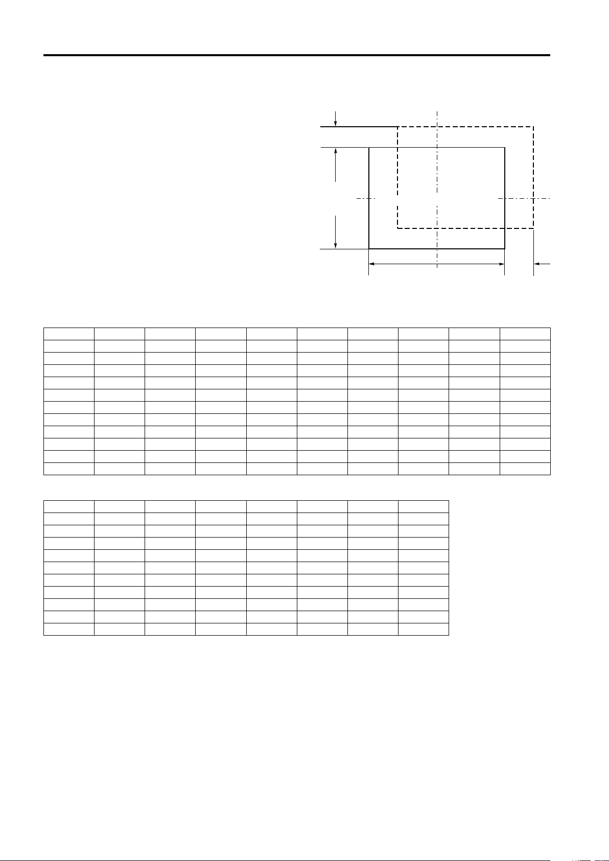
Maximum amount of shift
The maximum amount of vertical shift is restricted by the
amount of horizontal shift made.
The amount of shift is defined as follows:
With the screen width taken as 1, horizontal shift is defined
as a ratio (%) of the screen width, while with the screen
height taken as 1, vertical shift is defined as a ratio (%) of the
screen height.
Py (%)
Vertical
screen size
(y): 100%
Screen with zero (0) shift
Horizontal screen sized
Screen after shifted
(x): 100%
Relational table for maximum shift amounts (aspect ratio 4 : 3)
Py(%) Px(%) Py(%) Px(%) Py(%) Px(%) Py(%) Px(%) Py(%) Px(%)
0.000 31.968 10.000 28.102 20.000 23.272 30.000 17.268 40.000 9.739
1.000 31.621 11.000 27.666 21.000 22.729 31.000 16.592 41.000 8.881
2.000 31.265 12.000 27.219 22.000 22.173 32.000 15.900 42.000 8.000
3.000 30.901 13.000 26.762 23.000 21.606 33.000 15.192 43.000 7.096
4.000 30.528 14.000 26.295 24.000 21.026 34.000 14.467 44.000 6.167
5.000 30.146 15.000 25.818 25.000 20.434 35.000 13.725 45.000 5.213
6.000 29.756 16.000 25.331 26.000 19.828 36.000 12.966 46.000 4.231
7.000 29.356 17.000 24.833 27.000 19.209 37.000 12.189 47.000 3.221
8.000 28.948 18.000 24.324 28.000 18.577 38.000 11.392 48.000 2.180
9.000 28.530 19.000 23.803 29.000 17.930 39.000 10.576 49.000 1.107
50.000 0.000
Px
(%)
Relational table for maximum shift amounts (aspect ratio 16 : 9)
Py(%) Px(%) Py(%) Px(%) Py(%) Px(%) Py(%) Px(%)
0.000 31.968 10.000 26.609 20.000 19.421 30.000 9.747
1.000 31.503 11.000 25.980 21.000 18.581 31.000 8.599
2.000 31.234 12.000 25.333 22.000 17.716 32.000 7.410
3.000 31.528 13.000 24.666 23.000 16.824 33.000 6.178
4.000 30.018 14.000 23.980 24.000 15.905 34.000 4.900
5.000 29.491 15.000 23.274 25.000 14.958 35.000 3.573
6.000 28.949 16.000 22.548 26.000 13.981 36.000 2.193
7.000 28.389 17.000 21.800 27.000 12.973 37.000 0.756
8.000 27.813 18.000 21.030 28.000 11.933 37.509 0.001
9.000 27.220 19.000 20.237 29.000 10.858
16
Page 19
Installing the Projector
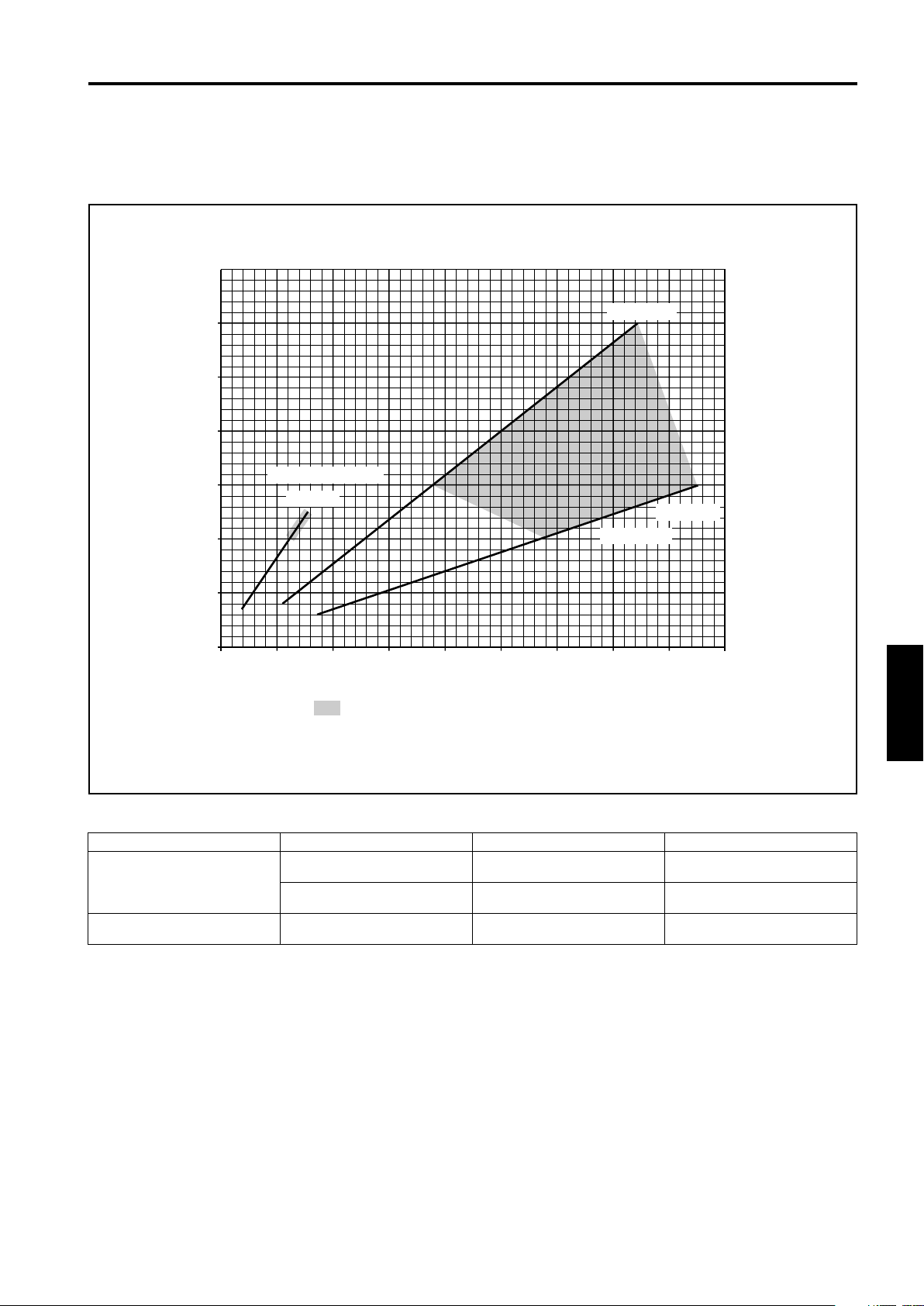
Projection Distances and Screen Sizes
Lenses that can be used are a 3 : 1 ~ 7 : 1 zoom lens and a 1.5 : 1 fixed-focus lens. With a zoom lens used, you have a wider
latitude in selecting projection distance and installation space than with a fixed lens.
For how to install the lens, consult the dealer who installed and adjusted your projector or service center.
Relationship of screen size vs. projection distance
600
WIDE 3 : 1
500
Screen Size (Type)
400
300
200
Fixed-Focus Lens
1.5 : 1
TELE 7 : 1
Zoom Lens
100
Projection
Distance (m)
510015 20 25 30 35 40
In the shaded areas in the above graph, the projected image may be partially distorted or
missed out depending on the distance between the projector and the screen. To project an image
with no image distortion or missing, we recommend you to use the projector in the areas defined
with solid lines in the graph.
45
ENGLISHDEUTSHFRANÇAISITALIANOESPAÑOL
Adjustable range of the lens
Lens Screen Size (Type) Projection Distance (m) Remarks
80 – 300
GL-M4023SZ zoom lens
GL-M4015S fixed-focus lens
The numbers in ( ) represent the minimum to maximum adjustable range.
(80 – 600)
60 – 200
(60 – 300)
69 – 208
(65 – 250)
(5.06 – 37.19)
(8.65 – 42.79)
5.06 – 18.65
8.65 – 28.56
2.09 – 6.50
(1.97 – 7.83)
3 : 1 wide
7 : 1 tele
––––––––
17
Page 20
Connecting to Various Devices
* Before connection, be sure to turn off the projector and connected devices.
* Read the manual which comes with each device thoroughly.
Signals that Can Be Input to the Projector
The following signals can be input to the projector:
Video signals
■
(1) Response to color systems
Input terminal
VIDEO*
3
Y/C*
Y, P
B
G, B, R, H/CS, V
Color system
3
/B-Y, PR/R-Y
*1: Responds if Y/C output is available.
*2: Signifies that component signals (“Y, P
(synchronization and video period) of each color system. The color systems are used for convenience only.
*3: To use these terminals, a video board (separately sold) is required.
(2) Response to double density (*1), high-vision signals
Input terminal
/B-Y, PR/R-Y
B
Y, P
G, B, R, H/CS, V
NTSC 480i NTSC 4.43 PAL SECAM
‡‡‡‡
‡
1
*
‡
2
*
‡
NTSC*
, PR” / “Y, B-Y, R-Y” / “G, B, R, H/CS, V”) conform to the signal timing
B
2222
High-vision signal
1
*
‡
2
*
‡
2
*
‡
‡
2
*
‡
2
*
‡
‡‡
‡‡
-----
‡
‡
2
*
2
*
*4: Signals whose density of scanning lines/field is twice as high.
*5: Responds to signals whose horizontal scanning frequency is 31.5 kHz. NTSC can be made twice as dense by a line
doubler (separately available: recommended article). Also, possible to respond to fully-specified, decoded 525P
progressive signals.
Note
• DTV-format signals (480i, 480p, 720p, 1080i) can be input into this unit (Y, PB/B-Y, PR/R-Y input terminals).
For details about DTV-format signals (480i, 480p, 720p, 1080i) compatible with this unit, refer to page 65.
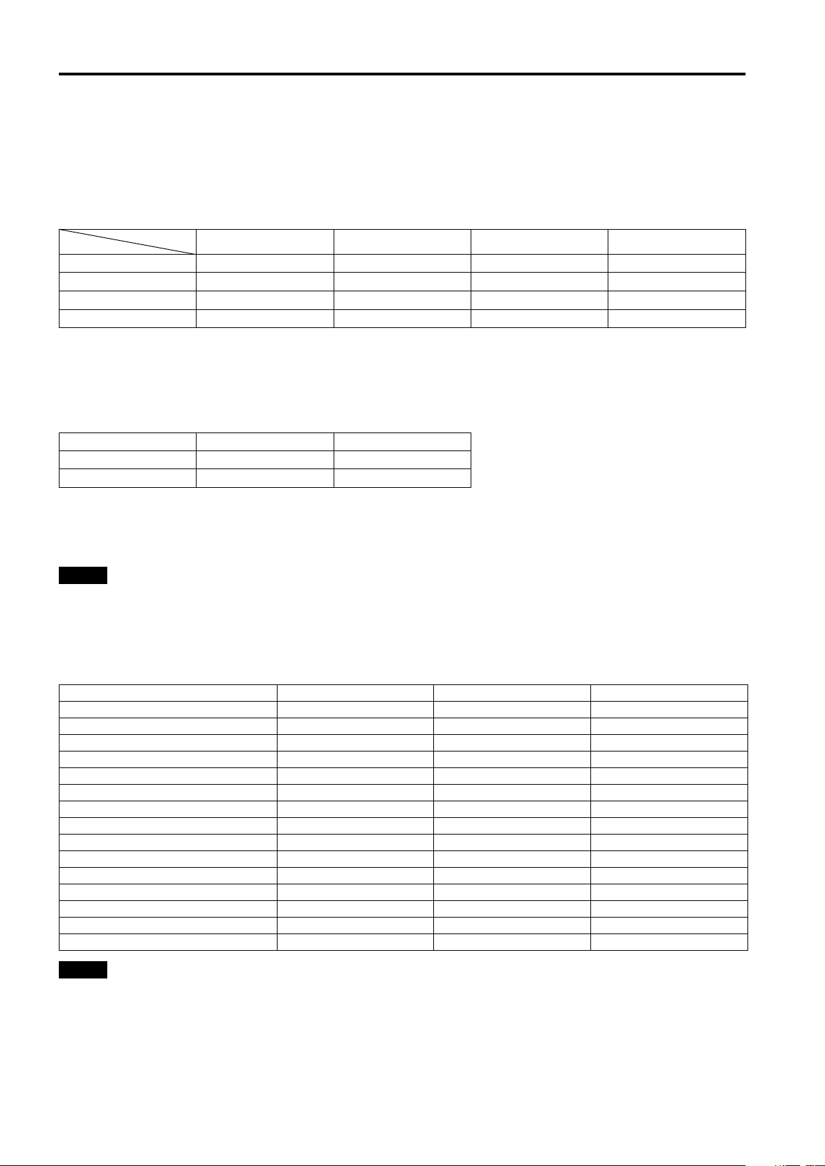
Computer signals
■
• Signals with the following resolutions can be input to the input terminal of RGB IN-1 (PC) or RGB IN-2 (G, B, R, H/CS, V).
(The following signals are preset.)
Screen resolution (standard name) Horizontal frequency Vertical frequency Scanning method
640 × 400 (PC-9801) 24.8kHz 56.4Hz Non-interlace
640 × 350 (VGA1) 31.5kHz 70.1Hz Non-interlace
640 × 480 (VGA3) 31.5kHz 59.9Hz Non-interlace
640 × 480 (Macintosh 13") 35.0kHz 66.7Hz Non-interlace
640 × 480 (VGA VESA) 37.5kHz 75.0Hz Non-interlace
800 × 600 (SVGA1) 37.9kHz 60.3Hz Non-interlace
800 × 600 (SVGA2) 48.1kHz 72.2Hz Non-interlace
832 × 624 (Macintosh 16") 49.7kHz 74.6Hz Non-interlace
1024 × 768 (XGA1) 48.4kHz 60.0Hz Non-interlace
1024 × 768 (XGA2) 56.5kHz 70.1Hz Non-interlace
1024 × 768 (Macintosh 19") 60.2kHz 74.9Hz Non-interlace
1152 × 870 (Macintosh 21") 68.7kHz 75.0Hz Non-interlace
1280 × 1024 (SXGA1) 64.0kHz 60.0Hz Non-interlace
1280 × 1024 (SXGA2) 70.8kHz 67.0Hz Non-interlace
1360 × 1024 (SXGA3: Mac Board) 80.0kHz 75.1Hz Non-interlace
Notes
• Interlace signals are not handled.
• Some signals other than listed above can be displayed. But they require adjustment. Even some of the signals listed above
may require adjustment depending on the video board used.
• When a signal other than listed above is input, the screen could be partially erased or an unneeded fold-over screen could
appear.
• Even signals in the frequency range that can be input may not be displayed normally depending on the type of the signal.
) and G on sync. signals can not handled depending on the devices connected.
• Composite sync.(C
S
18
Page 21
Connecting to Various Devices
Examples of System Configuration
Before connection, be sure to turn off both the projector and the equipment to be connected.
• Also, read the manuals which came with the equipment.
Example of a basic system
• By connecting an RGB switcher, a variety of input sources can be input to the projector as RGB signals. Using the
remote control supplied, you can select the channel for an input source and project an image optimal to the source.
HDTV 1
RGB switcher
Projector
HDTV 2
Y/C VIDEO
RGB
RGB IN-1
RGB IN-2
EXT. IN
R
Computer 1
GH/CS
BV PR/R-Y
REMOTE
RGB OUT
RS-232C
Y
B/B-Y
P
CONTROL
Computer 2
Note
• Video image displayed on devices whose image signal is unstable, such as a video deck, may be disturbed. (This can occur
when the projectors is not yet adjusted at the time of installation, or when a new device is added.)
In such a case, ask the dealer where you purchased the projector or a local service center to adjust the projector.
It is recommended that you use a video deck that is equipped with an image signal correction function (such as time base
corrector or frame synchronizer).
ENGLISHDEUTSHFRANÇAISITALIANOESPAÑOL
19
Page 22
Connecting to Various Devices
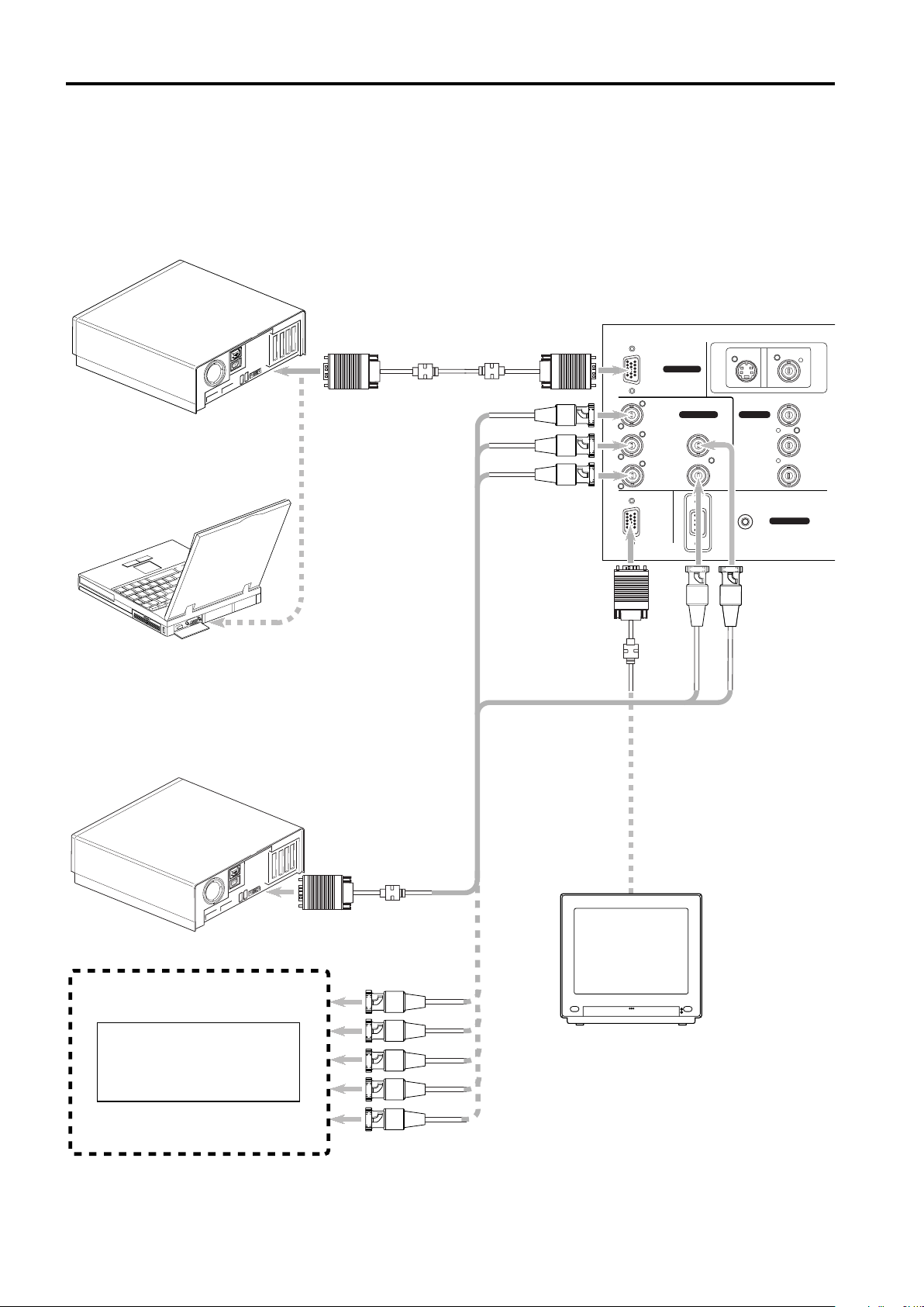
Connecting to Computer Devices
Before connection, be sure to turn off both the projector and computer devices.
• Read the manual which comes with each device thoroughly.
• Use the separately available computer connection cable. Also, prepare cables required for connecting the devices
connected.
• Desktop type
To RGB IN-1
Computer cable
(available separately)
RGB
RGB IN-1
Y/C VIDEO
To monitor connector
• Note type
* There are some note types which do not allow
the computer’s LCD to work if an external
display is connected.
With such a note type, the LCD display and
external display output need to be switched.
• Desktop type
Separate cable
(available separately)
To R
To G
RGB IN-2
R
G H/CS
EXT. IN
Y
B/B-Y
P
To B
BV PR/R-Y
RGB OUT
To RGB IN- 2
To RGB OUT
To Y
REMOTE
CONTROL
RS-232C
To H/CS
Cable supplied with the
display (or separately
available) (D-sub 3-row
15-pin)
• RGB output devices
Laser video disc player, etc.
20
To monitor connector
To R
To G
To B
To H/C
To V
POWER
Display monitor
S
* When a monitor is connected to the RGB
OUT terminal, you can view the video from
the computer on the monitor.
Page 23
Connecting to Various Devices
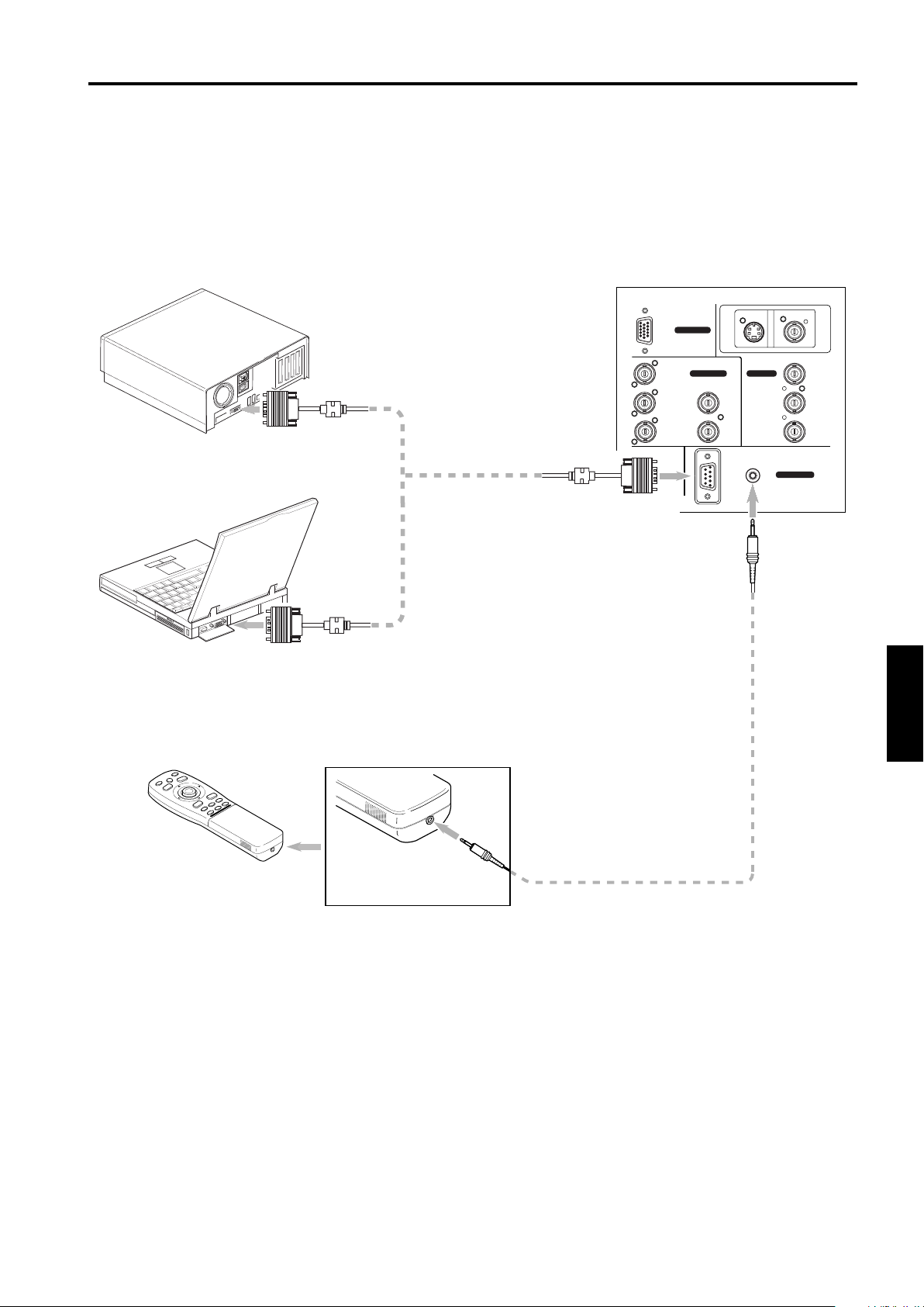
Connecting to Devices which Control the Projector
Before connection, be sure to turn off both the projector and devices to be connected.
• Read the manual thoroughly which comes with each device to be connected.
• By connecting a computer to the RS-232C terminal, you can control the projector.
* For details, consult an authorized your dealer or service center.
• If you connect the cable terminal of the remote control and the REMOTE terminal of the projector with a remote control
cable, you can use the remote control in a place or at an angle from which the infrared beam cannot reach the projector.
• Desktop type
To RS-232C connector
• Note type
To RS-232C connector
• Remote control (when remote control cable is used)
RS-232C reverse
connection cable
(available separately)
To RS-232C connector
RGB
RGB IN-1
RGB IN-2
R
G H/CS
BV PR/R-Y
RGB OUT
RS-232C
To REMOTE terminal
Y/C VIDEO
EXT. IN
REMOTE
CONTROL
Y
P
B/B-Y
ENGLISHDEUTSHFRANÇAISITALIANOESPAÑOL
To remote control
cable terminal
Remote control cable
21
Page 24
Connecting to Various Devices
Connecting the Power Cord (Supplied)
After all devices have finished being connected, connect the projector’s power cord. At this time, do not turn on the MAIN
POWER switch yet.
■ Preparation
Attach a plug which matches your wall outlet, to the power
cord. For how to attach a plug, consult your dealer or a
local service center.
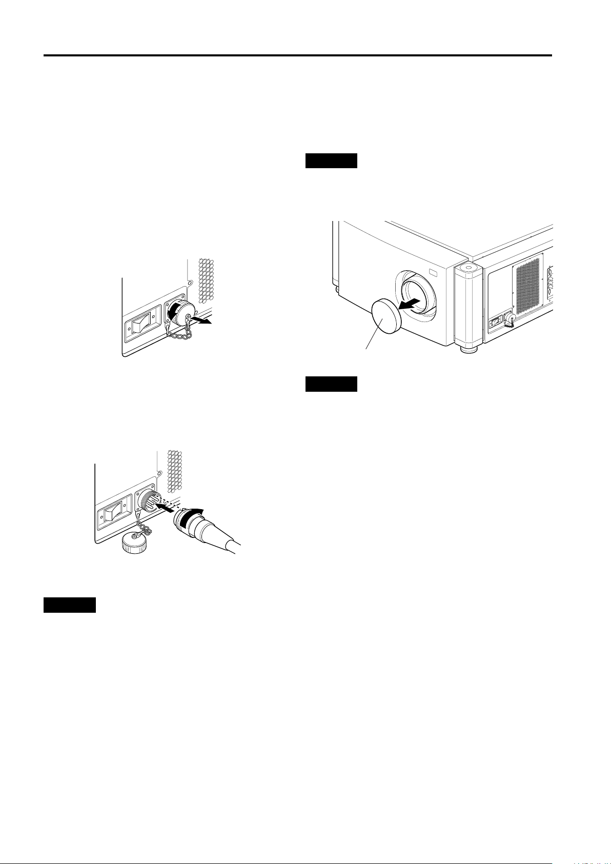
1 Insert the supplied power cord into the
power input terminal (AV IN ~) of the
projector.
1.Remove the power input terminal cover.
The cover is a screwed type. Turn the cover in the
direction of the arrow to remove.
2.Insert the projector plug of the supplied power
cord into the power input terminal of the projector.
Align the groove on the projector plug of the power
cord with the claw on the power input terminal of the
projector, and push the plug in firmly.
After that, turn the ring on the plug in the direction of
the arrow to fix.
■ To use the projector
• Remove the lens cap.
CAUTION
• Be sure to remove the cap; otherwise, it may be deformed
(or degraded in quality) or melted, possibly causing a fire or
malfunction.
Lens cap
CAUTIONS
To prevent fire and electric shock, observe the
following:
• When you do not use devices, pull out their power cords
from wall outlets.
• Do not connect the devices with power cords other than
supplied.
• Do not use voltage other than the power voltage indicated.
• Do not scar, damage, or work on the power cords. Also, do
not put a heavy object on, heat or pull the power cords,
otherwise they may be damaged.
• Do not insert or pull out the plugs with a wet hand.
2 Insert the plug of the supplied power cord
into a wall outlet.
CAUTIONS
• Since the power requirement of the projector is high, be
sure to insert the power plug directly into a wall outlet.
• This projector requires a single phase, 3-wire, 200V ~ 240V
wall outlet.
22
Page 25
Connecting to Various Devices
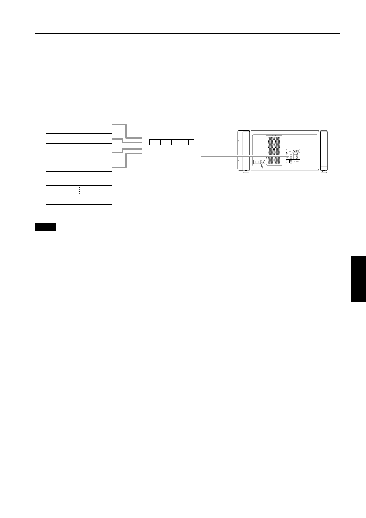
When Turning On the Devices Connected to the Projector
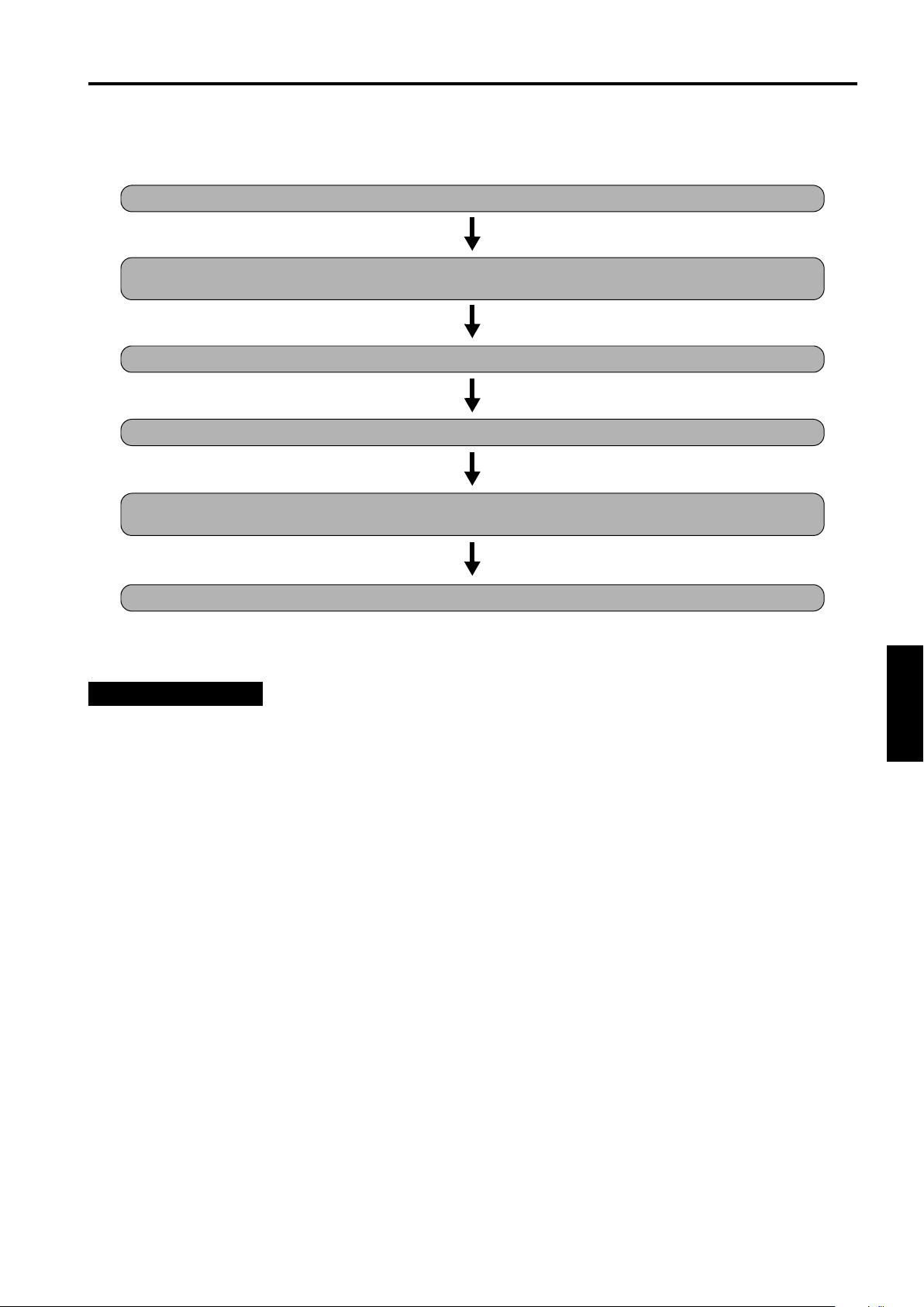
Turn on the switches of the projector and the devices connected in the following order.
Skip over unconnected devices if there is any.
Power switch of the monitor of the computer which provides input to the projector
Peripheral devices of the computer which provides input to the projector
(Hard disk, magneto optical disk, scanner, etc.)
Power switch of AV devices which provide input to the projector
Projector itself
Power switches of devices to which the projector provides output
(AV devices and display monitor)
Power switch of the computer which provides input to the projector
* When turning off the power switches, do so in the reverse order.
CAUTIONS and NOTES
Do not turn off the MAIN POWER switch suddenly while the projector is being used or immediately after it has been
used. This could cause a malfunction.
• Since the projector uses a high-intensity lamp and is heated to high temperature, cooling fans are operating even during
projection. So, after use, the cooling fans continue to run until the light-source lamp is sufficiently cooled down after the
OPERATE button was pressed. During the cooling-down, never turn off the main power switch. Turn it off only after the
cooling fans (except the one for the light-source lamp power supply) have stopped running. (The cooling fans will run for
about 10 minutes after the STAND BY indicator has changed from flashing (for about 20 seconds) to steady lighting.)
• If you press the OPERATE button immediately after the light-source lamp lights, it takes about 30 seconds for the lamp to go
off. To turn the lamp on again, wait 20 seconds or more before pressing the OPERATE button.
When the TEMP indicator lights, the power turns off automatically.
• While the light-source lamp is on, if an abnormal temperature rise is detected, the TEMP indicator comes on, the power is
automatically cut off, and the projector’s EMERGENCY indicator blinks (goes into an emergency mode).
When the EMERGENCY indicator blinks, turn off the main power switch after the fans have stopped running.
• If the following abnormality occur to the projector, it goes into an emergency mode (the EMERGENCY indicator blinks).
When the projector goes into an emergency mode, it stops projecting automatically and the cooling fans will continue to run
for about 10 minutes more before they stop (except the cooling fan for the light-source lamp power supply which continues
running as long as the MAIN POWER switch is on).
–When the light-source lamp suddenly goes off.
–When the fans stop running.
–When the temperature inside rises abnormally high.
• When the projector goes into an emergency mode:
After the fans have stopped, turn off the MAIN POWER switch and pull out the power cord. After that, re-insert the power
cord and try to operate the projector. If it goes into emergency again, after the fans have stopped, turn off the main power
switch, pull out the power cord, and consult your authorized dealer or service center for repair.
ENGLISHDEUTSHFRANÇAISITALIANOESPAÑOL
23
Page 26

Basic Operations
Projector’s buttons
■
STAND BY indicator
OPERATE indicator
STAND BY
OPERATE
OPERATE button
MAIN POWER switch 1,
LAMP
2
TEMP
EMERGENCY
The following describes the basic procedure for normal use
of the projector.
1. Turning on the Power
Turn on the MAIN POWER switch of the
1
projector.
ON [ ❙ ]: The main power turns on and the STAND BY
RGB
AV
1
,
2
Press the OPERATE button for one second
2
or more.
(Or press the remote control’s OPERATE
button for one second or more.)
• The OPERATE indicator comes on.
• About 30 seconds after the MAIN POWER switch is
turned on, you can start projecting.
Remote control unit
indicator comes on.
OPERATE
or
Projector’s indicator
STAND BY
Projector
OPERATE
Remote control unit
■
QUICK
ALIGN.
PRESET
LOCK UNLOCK
LENS
SHIFT ZOOM FOCUS
Caution on extended projection:
■
AV HIDE
PAGE BACK
M
RGB/COMPUTER
AV
UT
DW
LENS
OPERATE
E
N
U
/
E
+
–
OPERATE button 2,
N
T
E
R
1
When projection continues for an extended amount of
time, be sure to allow the lamp to be turned off for at
least two minutes for every 72 hours of continued
projection.
If you do otherwise, the service life of the lamp may be
severely affected.
Note
• After the power is turned on, the screen may be jumbled for
a few seconds, but this is not a malfunction.
Turning off the Power
■
Press the OPERATE button for one second
1
or more.
(Or press the remote control’s OPERATE
button for one second or more.)
• The STAND BY indicator changes to blinking, and the
projector goes into cool-down mode.
Example of the
projector’s button
Projector
\
OPERATE
Turn off the MAIN POWER switch after the
2
STAND BY
cooling fans have stopped running.
OFF [‡‡‡‡]: The MAIN POWER switch turns off and the
STAND BY indicator goes off.
Projector
STAND BY
* Do not turn off the MAIN POWER switch during cool
down mode (the STAND BY indicator blinking). About
10 minutes after the STAND BY indicator comes on
steady (stand-by mode), the cooling fans (except the
one for the light-source lamp power supply) will stop,
and then turn off the MAIN POWER switch.
24
Page 27
Basic Operations
■ Projector’s buttons
AV button
TEMP
EMERGENCY
LAMP
AV
RGB button
■ Remote control unit
LENS LOCK j UNLOCK switch
QUICK
ALIGN.
PRESET
LOCK UNLOCK
LENS
SHIFT ZOOM FOCUS
AV HIDE
PAGE BACK
M
RGB/COMPUTER
AV
UT
DW
LENS
OPERATE
E
N
U
/
E
+
–
N
T
E
R
SETTING
RGB
AV button
RGB button
ZOOM (T/W) buttons
QUICK
ALIGN.
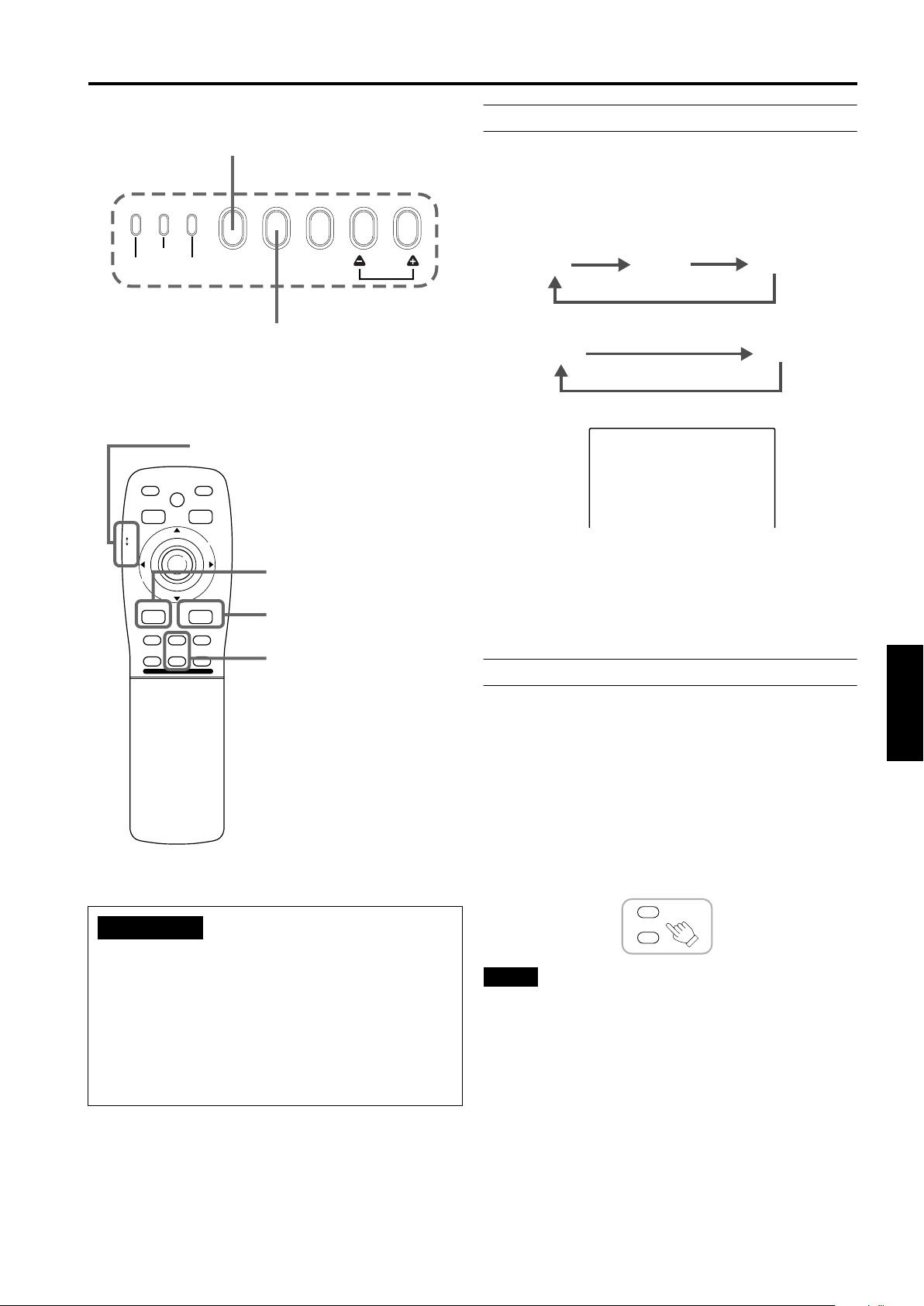
2. Select the video input to be projected
■ Press the AV button or the RGB button to
switch the input.
• Each time you press either button, the selected input
changes as follows.
When you press VIDEO:
Y/C
VIDEO
When you press COMPUTER:
RGB 1
Screen display
YPBPR
* When the input is switched, the line display and the
source display are shown on the upper part of the
screen (they disappear in about five seconds). However,
they will not be shown if LINE DISPLAY in “Setting and
Adjusting Other Functions (OPTIONS)” on page 40 is
set to OFF.
(For setting the source, see page 43.)
YPBPR
RGB 2
CH: 1
HDTV(1080i)
3. Adjust the screen size
ATTENTIONS
• DO NOT give any shock to this projector while
operating it; otherwise, the light-source lamp goes off
(the EMERGENCY indicator lights up).
If the shock turns off the light-source lamp —
Turn off the power by pressing the MAIN POWER
switch, then turn it on again. Then, when the STAND
BY indicator comes on, you can now operate the
projector as usual.
■ Adjust the screen size with the remote
control’s ZOOM (T/W) buttons.
When adjusting the screen size with the ZOOM buttons,
set the LENS LOCK j UNLOCK switch to the UNLOCK
position.
To enlarge the screen size:
Press the ZOOM (W) button.
To reduce the screen size:
Press the ZOOM (T) button.
Remote control unit
T
ZOOM
W
Notes
• The adjustment of the screen size (zoom adjustment) can
also be made on the setting menu.
For operating the setting menu, refer to “Making Basic
Settings” on page 29.
• When a fixed-focus lens is used, you cannot operate the
setting menu.
ENGLISHDEUTSHFRANÇAISITALIANOESPAÑOL
25
Page 28
Basic Operations
■ Projector’s buttons
EMERGENCY
RGB
AV
■ Remote control unit
LENS LOCK j UNLOCK switch
QUICK
ALIGN.
PRESET
LOCK UNLOCK
LENS
SHIFT ZOOM FOCUS
AV HIDE
PAGE BACK
M
E
RGB/COMPUTER
AV
UT
DW
LENS
OPERATE
N
U
/
E
N
T
+
–
E
R
SETTING
QUICK
ALIGN.
QUICK ALIGN. button
QUICK ALIGN. button
FOCUS (+/–) buttons
4. Adjust focus
■ Adjust focus with the remote control’s
FOCUS (+/–) buttons.
When adjusting the focus with the FOCUS buttons, set
the LENS LOCK j UNLOCK switch to the UNLOCK
position.
Remote control unit
+
FOCUS
–
Note
• Focus adjustment can also be made on the setting menu.
For operating the setting menu, refer to “Making Basic
Settings” on page 29.
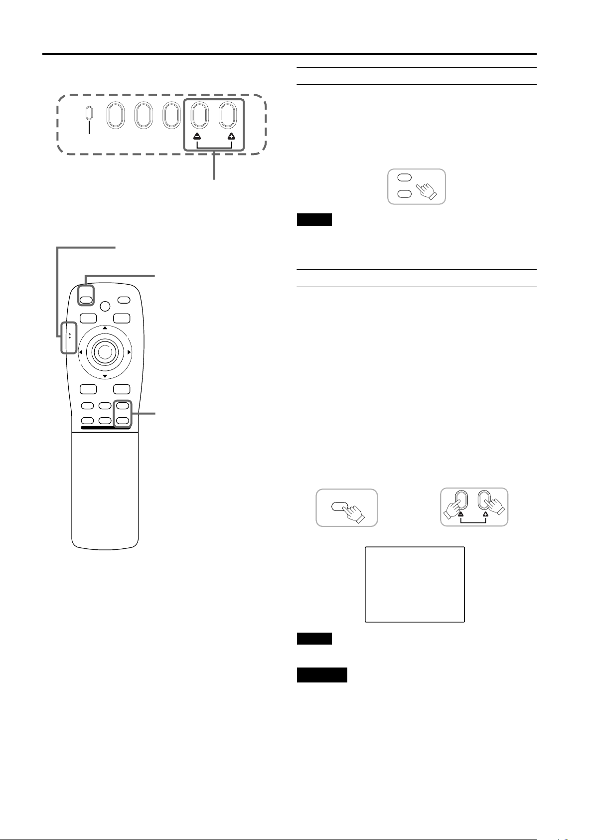
For Operating Other Functions
■ To use the quick alignment function
The quick alignment function is used to automatically
adjust (set) the screen settings of “TRACKING, PHASE,
H. POS. and V. POS.” of computer system input video.
• Use either the remote control’s or projector’s button.
When using the remote control unit:
Press the QUICK ALIGN. button.
When using the projector:
Clear the menu display, and press the projector’s QUICK
ALIGN. “++++” and “----” buttons at the same time.
* During the automatic adjustment, “QUICK-ALIGNMENT”
(Quick-Alignment) appears on the screen and
disappears automatically after the adjustment is
completed.
Remote control unit Projector
QUICK
ALIGN.
QUICK
ALIGN.
26
Screen display
QUICK-ALIGNMENT
Note
• This function works only for computer system inputs.
CAUTION
• When performing automatic adjustment using the
quick alignment function:
Use a bright, still-picture screen. It may not function
correctly on a dark or motion-picture screen.
If the condition adjusted by using the quick alignment
function is not good, manually adjust TRACKING, PHASE,
H. POS. and V. POS. (see pages 29, 35 and 36).
Page 29
Basic Operations
■ Projector’s button
TEMP
EMERGENCY
LAMP
AV
■ Remote control unit
QUICK
ALIGN.
PRESET
LOCK UNLOCK
LENS
AV
UT
SHIFT ZOOM FOCUS
DW
AV HIDE
LENS
OPERATE
PAGE BACK
M
E
N
U
/
E
N
T
E
R
RGB/COMPUTER
+
–
SETTING
RGB
SETTING button
PRESET button
MENU/ENTER button
QUICK
ALIGN.
■ To display the SETTING menu
The setting menu is used to make basic adjustments and
settings (TRACKING, PHASE, H. POS., V. POS., FOCUS
and ZOOM) of the video picture being projected after
installation (connection) or after inputs are switched. For
operating the setting menu, refer to “Making Basic
Settings” on page 29.
• Press the projector’s SETTING button.
The setting menu is displayed on the screen.
Remote control unit
SETTING
■ To display the MAIN menu
The main menu is used to adjust or set the projected
video picture and the projector’s condition, etc. (PIXEL
CLOCK, POSITION, PICTURE, OPTIONS, SOURCE,
DECODER and LANGUAGE). For operating the main
menu, refer to pages 32 to 57.
• Press the remote control’s MENU/ENTER button.
The main menu appears on the screen.
Remote control unit
Note
• To change the menu language displayed
English is set when the projector is shipped from the
factory. The language displayed can be selected from the
following six languages: N
DEUTSCH (German), ESPAÑOL (Spanish), ITALIANO
(Italian), and FRANÇAIS (French). However, some words
such as “QUICK-ALIGNMENT” (Quick-Alignment) are
displayed only in English. Pronouns such as line display
and source display are similarly treated.
M
E
N
U
/
E
N
T
E
R
N (Japanese), ENGLISH,
NN
ENGLISHDEUTSHFRANÇAISITALIANOESPAÑOL
■ To clear the MAIN menu
Use the PAGE BACK button to clear the main menu. For
how to operate the PAGE BACK button, see pages 32 to
57.
• While the main menu is displayed, press PAGE
BACK on the remote control.
The main menu will disappear.
Remote control unit
PAGE BACK
27
Page 30
Basic Operations
■ Remote control unit ■ To display “CHANNEL” on the screen
QUICK
ALIGN.
PRESET
LOCK UNLOCK
LENS
AV
UT
SHIFT ZOOM FOCUS
DW
AV HIDE
LENS
OPERATE
PAGE BACK
M
E
N
U
/
E
N
T
E
R
RGB/COMPUTER
+
–
AV HIDE button
PAGE BACK button
PRESET button
While no menu is displayed, pressing the PAGE BACK
button causes the channel now being used to appear.
You can also switch channels. For details, refer to “To
switch channels using a “DIRECT CHANNEL”” on
page 51.
• While no menu is displayed, press PAGE BACK on
the remote control.
The channel appears on the screen.
Remote control unit
PAGE BACK
■ To temporarily erase video image
Press the AV HIDE button, and video image will
temporarily disappear from the screen. Pressing the
button again will resume the video image.
• Press AV HIDE on the remote control.
Video image temporarily disappears from the screen.
Remote control unit
AV HIDE
■ To use the remote control’s PRESET button
The PRESET button is used for adjustments made on the
main menu or setting menu.
• When resetting only the selected settings to the
factory-set values, press the remote control’s
PRESET button.
Only the selected item’s setting is reset to the factory-set
value.
Remote control unit
PRESET
Notes
• This button works only for numeric values. It does not work
for switching between ON and OFF.
• For items such as PIXEL CLOCK (TRACKING and
PHASE), POSITION (H. POS. and V. POS.), both settings
are reset at the same time.
28
Page 31
Operating the Setting Menu
Making Basic Settings
■
Projector’s buttons
EMERGENCY
■
Setting menu
AV
SETTING
TRACKING
PHASE
H.POS.
V.POS.
FOCUS –
ZOOM W
SHIFT LENS
SETTING button
SETTING
RGB
QUICK ALIGN. button
10
In this section, we are making basic picture adjustments
which should be performed after installation (connection).
Notes
• The setting menu is displayed when you press the
SETTING button on the projector. After the menu is
displayed, you can make settings (adjustments).
• If the projector’s position or connections have been
changed, adjustments and settings should be performed
QUICK
ALIGN.
again.
• After adjustments, if further picture adjustment is necessary
depending on the equipment connected, use the main
menu (pages 32 to 57) to make detailed settings and
adjustments.
• For computer-related inputs, use of the quick alignment
function allows automatic adjustment of TRACKING,
PHASE, H. POS. and V. POS. (See pages 29, 35 and 36).
Press the SETTING button of the
1
projector.
• The setting menu is displayed on the screen.
0
0
0
+
T
Press the SETTING button to select the
2
desired item.
• The selected item is shown in magenta color. Each
time you press the button, the selected item changes
as follows:
TRACKING PHASE H. POS. V. POS.
Adjustment • setting level
Description of adjustment and setting items
TRACKING:
PHASE:
H. POS.:
V. POS.:
FOCUS:
ZOOM:
SHIFT LENS:
If wide vertical stripes appear on the screen, adjust
the lateral video size and display area so that they
disappear. (–255
If characters on the screen flicker or become dim,
adjust so they become clear. (–127
If the screen position is displaced to the right or left,
adjust the horizontal position of the screen.
(–255
If the screen position is displaced upward or
downward, adjust the vertical position of the screen.
(–120
Adjust the focus of video picture.
–: Focuses on near points.
+: Focuses on farther points.
Adjust the screen size (angle of view).
T: Becomes smaller.
W: Becomes larger
Adjusts the projected screen position.
∞: Moves it down.
5: Moves it up.
0 Ô +255)
Ô
0 Ô +120)
Ô
0 Ô +255)
Ô
0 Ô +127)
Ô
Menu clearing
SHIFT LENS
ZOOM
FOCUS
Memo
To select items using the remote control unit:
Items can be selected using the cursor buttons 5 (backward)
or ∞ (forward) on the remote control unit. In this case, menu
clearing in the above order is not available. The selection
changes from SHIFT LENS to TRACKING directly.
Adjust and set the selected item using
3
the QUICK ALIGN. buttons ++++ or ----.
• To adjust and set multiple items, repeat steps 2 and 3.
• To reset the adjustment value of the selected item
(TRACKING, PHASE, H. POS. or V. POS.) to the
factory-set value, press the remote control’s PRESET
button. This button does not work for focus and zoom.
Memo
To adjust and set items using the remote control unit:
Items can be adjusted or set by pressing the MENU/ENTER
button toward the 2 or 3 mark on the remote control.
Clear the setting menu by pressing the
4
SETTING button repeatedly.
Memo
To clear the setting menu using the remote control unit:
You can also clear the setting menu by pressing the PAGE
BACK button on the remote control unit.
ENGLISHDEUTSHFRANÇAISITALIANOESPAÑOL
29
Page 32

Operating the Main Menu
Configuration the Main Menu (AV Input)
For computer inputs, see the following page.
You can adjust video quality (PICTURE) and etc. using the menus.
The menus are configured as follows: Main menu (AV inputs: During EXT. IN input signal)
Main menu (AV inputs: During EXT. IN input signal)
PIXEL CLOCK
POSITION V. POS.: The vertical position of the video image being projected is adjusted.
PICTURE BRIGHTNESS: The brightness of the video image being projected is adjusted.
OPTIONS MENU AUTO OFF: Sets whether to turn off menu display automatically (YES) or not (NO).
SLEEP TIME: Sets the length of sleep time. A set sleep time after input signal is depleted, the projector
SOURCE: Normally used in AUTO. If use in AUTO is unstable such as color not appearing, the screen being disturbed or the
CHANNEL: Sets a line and multiple sources for each channel.
USER SOURCE
SET UP:
DISPLAY SIZE: This does not work for AV [EXT. IN (VIDEO, Y/C, YPBPR)] input signals. (Adjustment items are displayed in gray
DECODER: Normally, set to AUTO. The color system of an input signal is automatically identified and shown in ( ). When use in
LANGUAGE: Text on the screen can be changed to a language other than English. Languages that can be displayed are the
TRACKING: Normally, no adjustment is required. The lateral size and display area of video image are
PHASE: Normally, no adjustment is required. Flickering or dim video image is adjusted.
H. POS.: The horizontal position of the video image being projected is adjusted.
CONTRAST: The contrast of the video image being projected is adjusted.
SHARPNESS: The sharpness of the video image being projected is adjusted.
COLOR: The color density of the video image being projected is adjusted.
TINT: The tint of the video image being projected is adjusted. (Displayed only for NTSC signal)
ALL RESET: All the items adjusted are reset.
LINE DISPLAY: Sets whether to make the line display effective (ON) or not (OFF) for about 5 seconds
RIGHT LEFT REV.: Video image is reversed right-to-left.
TOP BOTTOM INV.: Video image is inverted top-to-bottom.
CLAMP: Sets the clamp pulse’s position at the back porch (BP) or on the sink tip (ST). Normally,
RESIZE: Does not work with AV (video) input. (RESIZE is shown in gray.)
BACK COLOR: Specifies the background color when there is no video signal. Background color can be
COLOR TEMP.: Adjusts the color temperature of the image being projected. Make adjustment when the
ASPET CHANGE: Selects the vertical-to-horizontal ratio of the image projected. The factory-set ratio is 4 : 3.
LAMP TIME: Indicates the accumulated used hours of the light-source lamp.
screen being intermitted, set to the dedicated source (forced mode) in accordance with the input signal.
USER allows you to set a source which is uniquely adjusted by the user.
Sets up an area for the source being input, and registers the user name.
color).
AUTO is unstable such as no color being shown, set the dedicated color system in accordance with the input signal.
You can select from AUTO, NTSC(480i), NTSC4.43, PAL, and SECAM.
following six:
(Italian), and FRANÇAIS (French). However, some text such as “QUICK-ALIGNMENT” (Quick-Alignment), etc. are
shown only in English.
N
N
NN
adjusted.
after input switching.
the clamp pulse is used at BP. If, with some PCs or workstations, the screen becomes
unstable such as being too dark or too bright, try to switch to ST.
selected from BLUE, CYAN, BLACK, GREEN, MAGENTA, RED, and YELLOW.
image becomes reddish or bluish.
Color temperature can be set to LOW, MIDDLE, or HIGH.
When projecting high-vision video image, a ratio of 16 : 9 can be selected.
goes into a stand-by state. Sleep time can be selected from 10 minutes, 20 minutes, 30
minutes, 60 minutes and 0 minutes. (If you select 0 minutes, the sleep time will be
cleared.)
(Japanese), ENGLISH (English), DEUTSCH (German), ESPAÑOL (Spanish), ITALIANO
30
Page 33

Operating the Main Menu
Configuration of the Main Menu (Computer-related input)
Main menu (Computer-related inputs: During COMPUTER IN -1 or -2 input signal)
PIXEL CLOCK TRACKING: The lateral size and display area of video image are adjusted.
PHASE: Flickering or dim video image is adjusted.
POSITION V. POS.: The vertical position of the video image being projected is adjusted.
H. POS.: The horizontal position of the video image being projected is adjusted.
PICTURE BRIGHTNESS: The brightness of the video image being projected is adjusted.
CONTRAST: The contrast of the video image being projected is adjusted.
R-GAIN: The gain in red signal of the video image being projected is adjusted.
G-GAIN: The gain in green signal of the video image being projected is adjusted.
B-GAIN: The gain in blue signal of the video image being projected is adjusted.
TEXT MODE: Adjust easiness for reading text during RESIZE.
ALL RESET: All the items adjusted are reset.
OPTIONS MENU AUTO OFF: Sets whether to turn off menu display automatically (YES) or not (NO).
LINE DISPLAY: Sets whether to make the line display effective (ON) or not (OFF) for about 5 seconds
RIGHT LEFT REV.: Image is reversed right-to-left.
TOP BOTTOM INV.: Image is inverted top-to-bottom.
CLAMP: Sets the clamp pulse’s position at the back porch (BP) or on the sink tip (ST). Normally,
RESIZE: When the number of pixels (resolution) sought by the video image input is smaller than
BACK COLOR: Specifies the background color when there is no image signal. Background color can be
COLOR TEMP.: Adjusts the color temperature of the video image being projected. Make adjustment when
ASPET CHANGE: Selects the vertical-to-horizontal ratio of the video image projected. The factory-set ratio
SLEEP TIME: Sets the length of sleep time. A set sleep time after input signal is depleted, the projector
LAMP TIME: Indicates accumulated used hours of the light-source lamp.
SOURCE: Normally used in AUTO. If use in AUTO is unstable such as color not appearing, the screen being disturbed or
CHANNEL: Sets a line and multiple sources for each channel.
USER SOURCE SET
UP:
DISPLAY SIZE: Adjusts H PIXEL, V PIXEL, H CENTER and V CENTER of video image.
DECODER: Does not work with computer-related inputs. (The color system is indicated in gray.)
LANGUAGE: Text on the screen can be changed to a language other than English. Languages that can be displayed are the
the screen being intermitted, set to the dedicated source (forced mode) in accordance with the input signal.
USER allows you to set a source which is uniquely adjusted by the user.
Sets up an area for the source being input, and registers the user name.
following six:
(Italian), and FRANÇAIS (French). However, some text such as “QUICK-ALIGNMENT” (Quick-Alignment), etc.
are shown only in English.
N
N
NN
NORMAL: Normal
TEXT 1: Display the outline of small letters already.
TEXT 2: Makes the outline of large letters sharp.
after input switching.
the clamp pulse is used at BP. If, with some PCs or workstations, the screen becomes
unstable such as being too dark or too bright, try to switch to ST.
that (resolution) of D-ILA device, the video image is then enlarged to a virtually full screen
size of D-ILA device and projected. (Resizing indication)
selected from BLUE, CYAN, BLACK, GREEN, MAGENTA, RED, and YELLOW.
the video image becomes reddish or bluish.
Color temperature can be set to LOW, MIDDLE, or HIGH.
is 4 : 3. When projecting high-vision image, a ratio of 16 : 9 can be selected.
goes into a stand-by state. Sleep time can be selected from 10 minutes, 20 minutes, 30
minutes, 60 minutes and 0 minute. (If you select 0 minutes, the sleep time will be
cleared.)
(Japanese), ENGLISH (English), DEUTSCH (German), ESPAÑOL (Spanish), ITALIANO
ENGLISHDEUTSHFRANÇAISITALIANOESPAÑOL
31
Page 34

Operating the Main Menu
Operating the Main Menu (Basic Operation of the Main Menu)
■ Remote control unit
QUICK
ALIGN.
PRESET
LOCK UNLOCK
LENS
AV
UT
SHIFT ZOOM FOCUS
DW
AV HIDE
LENS
OPERATE
PAGE BACK
M
E
N
U
/
E
N
T
E
R
RGB/COMPUTER
+
–
■ Main menu
Submenu items
Input line
YPBPR
PIXEL CLOCK
POSITION
PICTURE
OPTIONS
SOURCE
CHANNEL
USER SOURCE SET UP
DISPLAY SIZE
DECODER
LANGUAGE
Decoder (color system) Language
PAGE BACK button
MENU/ENTER button
Channel
Source
CH: 1
HDTV(1080i)
NTSC(480i)
ENGLISH
For projector’s menus, the setting menu and the main menu
are available.
Here, we explain about the operation of the main menu.
For the setting menu, refer to “Making Basic Settings” on
page 29.
Press the MENU/ENTER button.
1
• The main menu is displayed on the screen.
Press MENU/ENTER toward the 5 or ∞
2
mark to select an item.
• The selected item (displayed text) is shown in magenta
color on the screen.
Set (adjust) the item.
3
When you have selected DECODER or
language,
• Press MENU/ENTER toward the 2 or 3 mark to set.
* To finish the main menu, press the PAGE BACK button.
When you have selected an item on the
submenu,
• Press MENU/ENTER to display the submenu. Then,
set (adjust) the item by pressing MENU/ENTER toward
the 2/3 or 5/∞ mark.
* To return to the main menu, press PAGE BACK again.
To finish the main menu, press PAGE BACK again. (To
finish the main menu from the submenu, press PAGE
BACK twice.)
■ About main menu display:
Line display:
Source display:
Channel display:
Submenu item
display:
Decoder (Color
system) display:
Language display:
The selected input-mode designation is
displayed. For input-mode designation, “Y/C”,
“VIDEO”, “YPBPR”, “RGB 1” and “RGB 2” are
available.
The type of signal being input is displayed.
With this projector, unique designations are
previously given to specific horizontal and
vertical frequencies. This allows the source
selected under SOURCE (submenu item) to
be indicated. The source setting can be
selected from AUTO mode, dedicated (forced)
modes and USER mode. When AUTO is
selected, the horizontal and vertical
frequencies of a signal being input are
detected and the matched designation is
displayed in ( ).
Therefore, be careful as the source display
does not always correspond to the indication
or type of the input signal.
For the unique designations for the specific
horizontal and vertical frequencies, see
page 18.
The channel selected by the user is displayed.
The line and sources selected by the user
have been registered to the channel. Once
registered, the line and sources of the
projector will change to the ones the user has
registered only by switching between
channels. The settings should be made on the
“Channel setup/selection menu”. For details,
see page 46.
See pages 35 to 57.
See page 33.
See page 34.
32
Page 35

Changing the Color System
Operating the Main Menu
■ Remote control unit
QUICK
ALIGN.
PRESET
LOCK UNLOCK
LENS
AV
UT
SHIFT ZOOM FOCUS
DW
AV HIDE
LENS
OPERATE
PAGE BACK
M
E
N
U
/
E
N
T
E
R
RGB/COMPUTER
+
–
PAGE BACK button
MENU/ENTER button
AUTO is set for the color system when the projector is
shipped from the factory. Normally, use it in AUTO. If
operation in AUTO is unstable such as with color not being
shown, set to a dedicated color system in accordance with
the color system of the signal being input.
Press the MENU/ENTER button.
1
• The main menu is shown on the screen.
Press MENU/ENTER toward the 5 or ∞
2
mark to select “DECODER”.
• The selected item (displayed in text) is shown in
magenta color on the screen.
Press MENU/ENTER toward the 2 or 3
3
mark to set.
• Each time you press MENU/ENTER toward the 2 or 3
mark, the color system changes as follows:
3: Forward / 2: Backward
AUTO Normally, set to AUTO. The
color system of a signal being
input is automatically identified.
NTSC(480i) Dedicated to NTSC(480i).
■ Main menu
CH: 1
YPBPR
PIXEL CLOCK
POSITION
PICTURE
OPTIONS
SOURCE
CHANNEL
USER SOURCE SET UP
DISPLAY SIZE
DECODER
LANGUAGE
Color system (DECODER) display
Note
• When computer-related signal is input, the display of the
color system is changed to gray color, making operation
impossible. When video signals from AV devices are input,
the item for the color system can be set.
HDTV(1080i)
NTSC(480i)
ENGLISH
NTSC4.43 Dedicated to NTSC4.43.
PAL Dedicated to PAL.
SECAM Dedicated to SECAM.
Memo
About automatic signal identification
• AUTO is selected when shipped from the factory. In AUTO,
the color system (DECODER) of the signal being input is
automatically identified and indicated in ( ). Refer to the
main menu display.
• If operation in AUTO is unstable such as with color not
being shown, set to a dedicated color system in
accordance with the color system of the signal being input.
When the dedicated color system is set, be careful as
automatic identification does not work.
■ To finish the main menu, press the PAGE
BACK button.
ENGLISHDEUTSHFRANÇAISITALIANOESPAÑOL
33
Page 36

Operating the Main Menu
Changing the Language Display
■ Remote control unit
QUICK
ALIGN.
PRESET
LOCK UNLOCK
LENS
AV
UT
SHIFT ZOOM FOCUS
DW
AV HIDE
LENS
OPERATE
PAGE BACK
M
E
N
U
/
E
N
T
E
R
RGB/COMPUTER
+
–
PAGE BACK button
MENU/ENTER button
The language in the menu display is set to English when
shipped from the factory. When you want to change to
another language, set it as follows.
Press the MENU/ENTER button.
1
• The main menu is shown on the screen.
Press MENU/ENTER toward the 5 or ∞
2
mark to select “LANGUAGE”.
• The selected item (displayed in text) is shown in
magenta color on the screen.
Press MENU/ENTER toward the 2 or 3
3
mark to set.
• Each time you press MENU/ENTER toward the 2 or 3
mark, the selected language changes as follows:
3: Forward / 2: Backward
N
N ........ Japanese
NN
ENGLISH ........ English
DEUTSCH ........ German
■ Main menu
CH: 1
YPBPR
PIXEL CLOCK
POSITION
PICTURE
OPTIONS
SOURCE
CHANNEL
USER SOURCE SET UP
DISPLAY SIZE
DECODER
LANGUAGE
Language display
Note
• The selected item is shown in magenta color. Items shown
in gray cannot be operated or set in the current mode.
HDTV(1080i)
NTSC(480i)
ENGLISH
ESPAÑOL ........ Spanish
ITALIANO ........ Italian
FRANÇAIS ........ French
Memo
About language display
English is selected when the projector is shipped from the
factory. The languages in the menu display are the following
(Japanese), ENGLISH (English), DEUTSCH
N
N
six:
NN
(German), ESPAÑOL (Spanish), ITALIANO (Italian) and
FRANÇAIS (French).
However, some text such as “QUICK-ALIGNMENT” (QuickAlignment) is displayed only in English. Unique designations
such as line display and source display are similarly
indicated.
■ To finish the main menu, press the PAGE
BACK button.
34
Page 37

Adjusting the Pixel Clock
Operating the Main Menu
■ Remote control unit
QUICK
ALIGN.
PRESET
LOCK UNLOCK
LENS
AV
UT
SHIFT ZOOM FOCUS
DW
AV HIDE
LENS
OPERATE
PAGE BACK
M
E
N
U
/
E
N
T
E
R
RGB/COMPUTER
+
–
PAGE BACK button
MENU/ENTER button
The pixel clock should be adjusted mainly for computerrelated inputs. (Normally, it does not need to be adjusted for
video inputs.) If a wide stripe appears on the screen, adjust
the lateral size of video image and the display area (tracking
adjustment) so the stripe disappears.
Also, if text on the video screen appears flickering or dim,
make adjustment so it becomes clear (phase adjustment).
Press the MENU/ENTER button.
1
• The main menu appears on the screen.
Press MENU/ENTER toward the 5 or ∞
2
mark to select a submenu item, “PIXEL
CLOCK”.
• The selected item (displayed in text) is shown in
magenta color on the screen.
Press the MENU/ENTER button.
3
• The submenu items of the PIXEL CLOCK menu
appears on the screen.
PIXEL CLOCK
TRACKING PHASE
0 0
■ Main menu
CH: 1
YPBPR
PIXEL CLOCK
POSITION
PICTURE
OPTIONS
SOURCE
CHANNEL
USER SOURCE SET UP
DISPLAY SIZE
DECODER
LANGUAGE
Submenu item (PIXEL CLOCK)
Notes
• The selected item is shown in magenta color. Items shown
in gray color cannot be operated or set in the current mode.
• A dim screen could be caused by insufficient adjustment of
brightness and contrast. Before adjusting phase, make
sure that brightness and contrast are correctly adjusted.
HDTV(1080i)
NTSC(480i)
ENGLISH
(PIXEL CLOCK menu)
Press MENU/ENTER toward the 2, 3,
4
5 or ∞ mark to adjust “TRACKING”
and “PHASE”.
• Adjust the tracking and phase of the video screen
being projected. To adjust the phase, first check for
correct tracking adjustment.
Adjustment item Button Adjustment content
The screen shrinks laterally
(right-to-left).
2
TRACKING
PHASE
(–255
The screen extends laterally
(right-to-left).
3
(–255
Set to a position where text
appears clear.
(–127 = 0 = +127)
5
(–127 + 0 + +127)
∞
* To reset to the factory-set adjustment values, press the
remote control’s PRESET button.
Tracking and phase are reset to the factory-set
adjustment values.
0 + +255)
+
0 = +255)
=
ENGLISHDEUTSHFRANÇAISITALIANOESPAÑOL
■ To return to the main menu, press the PAGE
BACK button. To finish the main menu,
press PAGE BACK again.
• To finish the menu display from the submenu display
(PIXEL CLOCK menu), press PAGE BACK twice.
35
Page 38

Operating the Main Menu
Adjusting the Screen Position
■ Remote control unit
QUICK
ALIGN.
PRESET
LOCK UNLOCK
LENS
AV
UT
SHIFT ZOOM FOCUS
DW
AV HIDE
LENS
OPERATE
PAGE BACK
M
E
N
U
/
E
N
T
E
R
RGB/COMPUTER
+
–
PAGE BACK button
MENU/ENTER button
Adjust the position of the screen if it is displaced.
Press the MENU/ENTER button.
1
• The main menu appears on the screen.
Press MENU/ENTER toward the 5 or ∞
2
mark to select a submenu item,
“POSITION”.
• The selected item (displayed in text) is shown in
magenta color on the screen.
Press the MENU/ENTER button.
3
• The submenu items of the POSITION menu appear on
the screen.
POSITION
H.POS. V.POS.
0 0
(POSITION menu)
■ Main menu
CH: 1
YPBPR
PIXEL CLOCK
POSITION
PICTURE
OPTIONS
SOURCE
CHANNEL
USER SOURCE SET UP
DISPLAY SIZE
DECODER
LANGUAGE
Submenu item (POSITION)
Note
• The selected item is shown in magenta color. Items shown
in gray color cannot be operated or set in the current mode.
HDTV(1080i)
NTSC(480i)
ENGLISH
Press MENU/ENTER toward the 2, 3,
4
5 or ∞ mark to adjust “H. POS.” and
“V. POS.”.
• Adjust the horizontal and vertical positions of the video
picture screen being projected.
Adjustment item Button Adjustment content
The screen moves to the left.
2
H. POS.
V. POS.
(–255
The screen moves to the
3
right. (–255
The screen moves upwards.
5
(–120
The screen moves
downwards.
∞
(–120
* To reset to the factory-set adjustment values, press the
remote control’s PRESET button. H. POS. and V. POS.
are reset to the factory-set adjustment values.
■ To return to the main menu, press the PAGE
BACK button. To finish the main menu,
press PAGE BACK again.
• To finish the menu display from the submenu display
(POSITION menu), press PAGE BACK twice.
0 + +255)
+
=
0 = +120)
=
0 + +120)
+
0 = +255)
36
Page 39

Adjusting Picture Quality
Operating the Main Menu
■ Remote control unit
QUICK
ALIGN.
PRESET
LOCK UNLOCK
LENS
AV
UT
SHIFT ZOOM FOCUS
DW
AV HIDE
LENS
OPERATE
PAGE BACK
M
E
N
U
/
E
N
T
E
R
RGB/COMPUTER
+
–
PAGE BACK button
MENU/ENTER button
Adjust brightness, contrast, etc. so you have the desired
screen. Adjustment items (on the PICTURE menu) are
different when video-related signals are input and when
computer-related signals are input.
Press the MENU/ENTER button.
1
• The main menu appears on the screen.
Press MENU/ENTER toward the 5 or ∞
2
mark to select a submenu item,
“PICTURE”.
• The selected item (displayed in text) is shown in
magenta color on the screen.
Press the MENU/ENTER button.
3
• The submenu items of the PICTURE menu appear on
the screen.
When AV signals are input
PICTURE
(NTSC(480i))
BRIGHTNESS
CONTRAST
SHARPNESS
COLOR –
TINT
ALL RESET
0
0
3
3
1
■ Main menu
CH: 1
YPBPR
PIXEL CLOCK
POSITION
PICTURE
OPTIONS
SOURCE
CHANNEL
USER SOURCE SET UP
DISPLAY SIZE
DECODER
LANGUAGE
Submenu item (PICTURE)
Notes
• The selected item is shown in magenta color. Items shown
in gray color cannot be operated or set in the current mode.
• Adjustment items (on the PICTURE menu) are different
when AV signals are input and when computer-related
signals are input.
HDTV(1080i)
NTSC(480i)
ENGLISH
(Video-image PICTURE menu)
When computer-related signals are input
PICTURE
(SXGA2)
BRIGHTNESS
CONTRAST
R-GAIN
G-GAIN
B-GAIN
TEXT MODE NORMAL
ALL RESET
0
0
0
0
0
(Computer-image PICTURE menu)
Press MENU/ENTER toward the 5 or ∞
4
mark to select the item to adjust.
• The selected item (displayed in text) is shown in
magenta color.
ENGLISHDEUTSHFRANÇAISITALIANOESPAÑOL
(To be continued on the next page)
37
Page 40

Operating the Main Menu
Adjusting Picture Quality (Cont.)
■ Remote control unit
QUICK
ALIGN.
PRESET
LOCK UNLOCK
LENS
AV
UT
SHIFT ZOOM FOCUS
DW
AV HIDE
LENS
OPERATE
PAGE BACK
M
E
N
U
/
E
N
T
E
R
RGB/COMPUTER
+
–
■ Submenu items
[PICTURE menu]
PICTURE
(NTSC(480i))
BRIGHTNESS
CONTRAST
SHARPNESS
COLOR –
TINT
ALL RESET
PAGE BACK button
MENU/ENTER button
0
0
3
3
1
Press MENU/ENTER toward the 2 or 3
5
mark to adjust the selected item.
For video system input
• To adjust multiple items, repeat steps 4 and 5.
• To reset all items (to factory-set adjustment values,
“0”), press MENU/ENTER toward the 5 or ∞ mark to
select “ALL RESET”, and press MENU/ENTER.
• To reset only the selected items (ALL RESET
excluded) to the factory-set adjustment value, press
the remote control’s PRESET button. The selected
item is reset to the factory-set adjustment value.
Adjustment item Button Adjustment content
Gets darker.
2
(–30
0 + +30)
BRIGHTNESS
3
2
CONTRAST
3
2
SHARPNESS
3
2
COLOR
3
2
TINT
3
ALL RESET
MENU/
ENTER
Notes
• The adjustment item, TINT, is displayed only for NTSC
system. It is not displayed (cannot be adjusted) when PAL
or SECAM system signals are input.
• When video signals are input to the COMPUTER IN-2
terminal, adjustment items “COLOR” and “TINT” are
indicated but cannot be adjusted.
+
Gets brighter.
(–30
0 = +30)
=
Gets lower.
(–30
0 + +30)
+
Gets higher.
(–30
0 = +30)
=
Gets softer.
(0
7)
+
Gets sharper.
(0
7)
=
Gets softer.
(–30
0 + +30)
+
Gets deeper.
(–30
0 = +30)
=
Gets reddish.
(–30
0 + +30)
+
Gets greenish.
(–30
0 = +30)
=
Resets all adjustment values
of items on the PICTURE
menu to the factory-set
values (0).
Notes
• The selected item is shown in magenta color. Items shown
in gray color cannot be operated or set in the current mode.
• Adjustment items (on the PICTURE menu) are different
when AV signals are input and when computer-related
signals are input.
38
■ For computer system input
• To adjust multiple items, repeat steps 4 and 5.
• To reset all items (to factory-set adjustment values, “0”),
press MENU/ENTER toward the 5 or ∞ mark to select
“ALL RESET”, and press MENU/ENTER.
• To reset only the selected items (ALL RESET excluded)
to the factory-set adjustment value, press the remote
control’s PRESET button. The selected item is reset to
the factory-set adjustment value.
(To be continued on the next page)
Page 41

Adjusting Picture Quality (Cont.)
■ Remote control unit
QUICK
ALIGN.
PRESET
LOCK UNLOCK
LENS
AV
UT
SHIFT ZOOM FOCUS
DW
■ Submenu items
AV HIDE
LENS
OPERATE
PAGE BACK
M
E
N
U
/
E
N
T
E
R
RGB/COMPUTER
+
–
[PICTURE menu]
PAGE BACK button
MENU/ENTER button
Operating the Main Menu
Adjustment item Button Adjustment content
Gets darker.
2
(–30
0 + +30)
BRIGHTNESS
CONTRAST
R-GAIN
G-GAIN
B-GAIN
TEXT MODE
ALL RESET
3
2
3
2
3
2
3
2
3
2
3
MENU/
ENTER
+
Gets brighter.
(–30
0 = +30)
=
Gets lower.
(–30
0 + +30)
+
Gets higher.
(–30
0 = +30)
=
Gets less reddish.
(–30
0 + +30)
+
Gets more reddish.
(–30
0 = +30)
=
Gets less greenish.
(–30
0 + +30)
+
Gets more greenish.
(–30
0 = +30)
=
Gets less bluish.
(–30
0 + +30)
+
Gets more bluish.
(–30
0 = +30)
=
Sets a mode which allows
easy text reading.
NORMAL
NORMAL TEXT 1
TEXT 2
Resets all adjustment values
of items on the PICTURE
quality menu to the factoryset status (adjustment
values: 0, text mode:
NORMAL).
TEXT 1
TEXT 2
PICTURE
(SXGA2)
BRIGHTNESS
CONTRAST
R-GAIN
G-GAIN
B-GAIN
TEXT MODE NORMAL
ALL RESET
0
0
0
0
0
Notes
• The selected item is shown in magenta color. Items shown
in gray color cannot be operated or set in the current mode.
• Adjustment items (on the PICTURE menu) are different
when AV signals are input and when computer-related
signals are input.
Note
• There is a relationship between the adjustment of items RGAIN, G-GAIN, and B-GAIN and that of item CONTRAST.
For example, when adjustment values are: R-GAIN: 0, GGAIN: 5, B-GAIN: 0, and CONTRAST: 0, changing
CONTRAST to 1 changes the adjustment values as
follows: R-GAIN: 1, G-GAIN: 6, and B-GAIN: 1.
Also, when the adjustment value of any of R-GAIN, GGAIN, and B-GAIN has reached -30 (minimum) or +30
(maximum), CONTRAST cannot be adjusted to any higher
value. For example, when R-GAIN is 0, G-GAIN is 5, BGAIN is 0, and CONTRAST is 0, increasing CONTRAST
allows the other adjustment values to increase until RGAIN: 25, G-GAIN: 30, and B-GAIN: 25, then CONTRAST
becomes 25 and cannot be adjusted to any higher value.
■ To return to the main menu, press the BACK
COLOR button. To finish the main menu,
press PAGE BACK again.
• To finish the menu display from the submenu display
(PICTURE menu), press PAGE BACK twice.
ENGLISHDEUTSHFRANÇAISITALIANOESPAÑOL
39
Page 42

Operating the Main Menu
Setting and Adjusting Other Functions (OPTIONS)
■ Remote control unit
QUICK
ALIGN.
PRESET
LOCK UNLOCK
LENS
AV
UT
SHIFT ZOOM FOCUS
DW
AV HIDE
LENS
OPERATE
PAGE BACK
M
E
N
U
/
E
N
T
E
R
RGB/COMPUTER
+
–
PAGE BACK button
MENU/ENTER button
The following optional functions can be set (adjusted).
• MENU AUTO OFF • LINE DISPLAY • RIGHT LEFT REV.
• TOP BOTTOM INV. • CLAMP • RESIZE
• BACK COLOR • COLOR TEMPERATURE
• ASPET CHANGE • SLEEP TIME • LAMP TIME
Memo
About the lamp use time
The lamp use time indicates the accumulated used hours of
the light-source lamp and cannot be set or adjusted. When
you have replaced with a new light-source lamp, reset the
lamp use time.
Note
• The RESIZE function works for only computer system
input. It does not work for video system input.
Press the MENU/ENTER button.
1
• The main menu appears on the screen.
Press MENU/ENTER toward the 5 or ∞
2
mark to select a submenu item,
“OPTION”.
• The selected item (displayed in text) is shown in
magenta color on the screen.
■ Main menu
CH: 1
YPBPR
PIXEL CLOCK
POSITION
PICTURE
OPTIONS
SOURCE
CHANNEL
USER SOURCE SET UP
DISPLAY SIZE
DECODER
LANGUAGE
Submenu item (OPTIONS)
Notes
• The selected item is shown in magenta color. Items shown
in gray color cannot be operated or set in the current mode.
• Items to be set (adjusted) are different when AV signals are
input and when computer system signals are input.
HDTV(1080i)
NTSC(480i)
ENGLISH
Press the MENU/ENTER button.
3
• The submenu items of the options menu are displayed.
OPTIONS
MENU AUTO OFF
LINE DISPLAY
RIGHT LEFT REV.
TOP BOTTOM INV.
CLAMP
RESIZE
BACK COLOR
COLOR TEMP.
ASPECT CHANGE
SLEEP TIME
LAMP TIME
NO
ON
OFF
OFF
BP
ON
BLUE
MIDDLE
4:3
0 Min.
10 H.
(OPTIONS menu)
Press MENU/ENTER toward the 5 or ∞
4
mark to select an item to set (adjust).
• The selected item (displayed in text) is shown in
magenta color.
40
(To be continued on the next page)
Page 43

Operating the Main Menu
Setting and Adjusting Other Functions (OPTIONS) (Cont.)
■ Remote control unit
QUICK
LOCK UNLOCK
LENS
ALIGN.
PRESET
AV HIDE
OPERATE
PAGE BACK
M
E
N
U
/
E
N
T
PAGE BACK button
E
R
MENU/ENTER button
RGB/COMPUTER
AV
UT
SHIFT ZOOM FOCUS
DW
LENS
+
–
■ Submenu items
[OPTIONS menu]
OPTIONS
MENU AUTO OFF
LINE DISPLAY
RIGHT LEFT REV.
TOP BOTTOM INV.
CLAMP
RESIZE
BACK COLOR
COLOR TEMP.
ASPECT CHANGE
SLEEP TIME
LAMP TIME
Notes
• The selected item is shown in magenta color. Items shown
in gray color cannot be operated or set in the current mode.
• Items to be set (adjusted) are different when AV signals are
input and when computer-system signals are input.
• When you turn the RESIZE function ON, allowing the
screen to be enlarged virtually to its full size for projection
(resizing display), the video image (resolution) becomes
coarse.
NO
ON
OFF
OFF
BP
ON
BLUE
MIDDLE
4:3
0 Min.
10 H.
Press MENU/ENTER toward the 2 or 3
5
mark to select an item to set (adjust).
• To adjust multiple items, repeat steps 4 and 5.
Adjustment
item
MENU
AUTO OFF
LINE
DISPLAY
RIGHT
LEFT REV.
TOP
BOTTOM
INV.
CLAMP
RESIZE
Button Adjustment content
Sets whether to clear the menu
display automatically a fixed time
later or not.
(Factory setting: NO)
YES:
2/3
Clears the display
automatically in about 25
seconds.
NO:
Does not clear the display
automatically.
YES
NO
j
Sets whether to show the line
display (Y/C, VIDEO, etc.) at the top
of the projected screen or not.
(Factory setting: ON)
OFF:
Does not show the line
2/3
display.
ON:
Shows the line display. (The
line display disappears
about 5 seconds after it is
shown.)
ON
j
For the front method
For upside hanging from the
ceiling
ON
j
For normal set-up
For upside hanging from the
ceiling
ON
j
2/3
2/3
OFF
Reverses video image right-to-left.
(Factory setting: OFF)
OFF:
ON:
OFF
Inverses video image upside-down.
(Factory setting: OFF)
OFF:
ON:
OFF
Sets the clamp pulse’s position at
the back porch (BP) or on the sink
tip (ST). Normally, the clamp is used
at BP. If, with some PCs or
workstations, the screen becomes
unstable such as being too dark or
2/3
too bright, try to switch to ST.
(factory setting: BP)
BP:
The clamp pulse is
positioned at the back porch.
ST:
The clamp pulse is
positioned on the sink tip.
BP
ST
j
When the number of pixels
(resolution) sought by the input
video is smaller than that
(resolution) of D-ILA device, the
video image is then enlarged to
virtually full screen size of D-ILA
device and projected (resizing
display). (Factory setting: ON) Does
not work (cannot be set) for video
system input.
OFF:
Does not enlarge the video
2/3
image for projection. When
the number of pixels sought
by video image is smaller
than that of D-ILA device,
projection takes place on a
small screen size with a
black area around the
screen.
ON:
Enlarges virtually to the full
screen size of D-ILA device
for projection (resizing
display).
OFF
j
ON
ENGLISHDEUTSHFRANÇAISITALIANOESPAÑOL
(To be continued on the next page)
41
Page 44
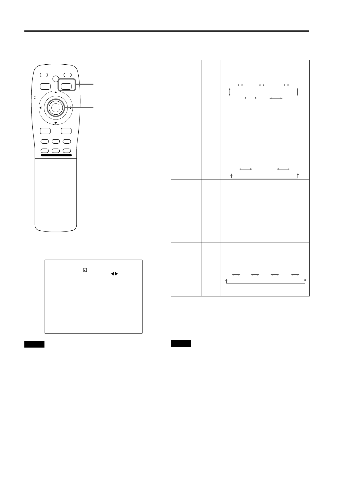
Operating the Main Menu
Setting and Adjusting Other Functions (OPTIONS) (Cont.)
■ Remote control unit
QUICK
ALIGN.
PRESET
LOCK UNLOCK
LENS
AV
UT
SHIFT ZOOM FOCUS
DW
AV HIDE
LENS
OPERATE
PAGE BACK
M
E
N
U
/
E
N
T
E
R
RGB/COMPUTER
+
–
■ Submenu items
[OPTIONS menu]
OPTIONS
MENU AUTO OFF
LINE DISPLAY
RIGHT LEFT REV.
TOP BOTTOM INV.
CLAMP
RESIZE
BACK COLOR
COLOR TEMP.
ASPECT CHANGE
SLEEP TIME
LAMP TIME
PAGE BACK button
MENU/ENTER button
NO
ON
OFF
OFF
BP
ON
BLUE
MIDDLE
4:3
0 Min.
10 H.
Adjustment
item
BACK
COLOR
COLOR
TEMP.
ASPET
CHANGE
SLEEP
TIME
■ To return to the main menu, press the PAGE
BACK button. To finish the main menu,
press PAGE BACK again.
• To finish the menu display from the submenu display
(options menu), press PAGE BACK twice.
Button Adjustment content
Sets background color when there is no
input signal. (Factory setting: BLUE)
2/3
BLUE CYAN
YELLOW
Sets the color temperature of the video
image being projected. Make adjustment
when the image becomes reddish or
bluish. (Factory setting: MIDDLE)
LOW:
MIDDLE:
2/3
HIGH:
LOW
BLACK GREEN
RED
Color temperature
decreases (video image
becoming reddish).
Results in middle color
temperature.
Color temperature increases
(video image becoming
bluish).
MIDDLE HIGH
Sets the vertical-to-horizontal ratio (4 : 3
or 16 : 9) of the video image projected.
(Factory setting: 4 : 3)
4 : 3:
2/3
16 : 9:
The aspect ratio of the
screen becomes 4 : 3. Set it
to 4 : 3 for video of NTSC,
NTSC4.43, PAL, SECAM.
The aspect ratio of the
screen becomes 16 : 9. Set
it to 16 : 9 for Hi-Vision
devices (W-VHS VCR, etc.)
j
16 : 9
4 : 3
Sets the length of sleep time which
automatically brings the projector into
stand-by state. You can select one of the
following sleep times: 10 minutes, 20
minute, 30 minutes, 60 minutes and 0.
(Factory setting: 0 minutes)
2/3
10 20 60 030
If set to “0” minutes, this function does
not work.
MAGENTA
Notes
• The selected item is shown in magenta color. Items shown
in gray color cannot be operated or set in the current mode.
• Items to be set (adjusted) are different when AV signals are
input and when computer-system signals are input.
42
Note
• When you view a conventional (normal) 4 : 3 video picture,
which is not wide video picture, on the projector’s screen
the aspect change function, the upper and lower parts of
the video picture become partially invisible. View such an
original video picture in 4 : 3 mode, respecting the
producer’s intention.
Page 45

Changing (Setting) the Source
Operating the Main Menu
■ Remote control unit
QUICK
ALIGN.
PRESET
LOCK UNLOCK
LENS
AV
UT
SHIFT ZOOM FOCUS
DW
AV HIDE
LENS
OPERATE
PAGE BACK
M
E
N
U
/
E
N
T
E
R
RGB/COMPUTER
+
–
PAGE BACK button
MENU/ENTER button
Normally, use the source setting in AUTO. If use in AUTO is
unstable such as color not appearing, the screen being
disturbed or the screen being intermitted, set to the
dedicated source (forced mode) in accordance with the input
signal.
Also, USER mode, which is a user-dedicated source, is
available.
• When shipped from the factory, the source settings are as
follows:
Input mode
Factory
setting
Input mode
VIDEO PAL/SECAM RGB 1 AUTO
Y/C PAL/SECAM RGB 2 AUTO
YPBPR AUTO ——
Factory
setting
Notes
• Depending on the signal from a device connected,
adjustment may be needed after a dedicated source is set.
If that is the case, adjust the appropriate items.
• When the input mode (SOURCE) is VIDEO or Y/C, and if
AUTO is set, the automatic detecting function may work,
possibly causing the screen to be intermitted or disturbed.
In that case, set to a dedicated source (forced mode).
• When special effect playback (fast-forward/twice-speed/
triple-speed) is performed on a video deck, etc., the picture
may be disturbed or intermitted, depending on the device.
• When inputting 480p or 720p-DTV-format signal in RGB 2
input mode, use the dedicated source cannot be detected.
■ Main menu
CH: 1
YPBPR
PIXEL CLOCK
POSITION
PICTURE
OPTIONS
SOURCE
CHANNEL
USER SOURCE SET UP
DISPLAY SIZE
DECODER
LANGUAGE
Submenu item [SOURCE]
Notes
• The selected item is shown in magenta color. Items shown
in gray color cannot be operated or set in the current mode.
• Items that can be set are different when video signals are
input and when computer signals are input.
• For dedicated source signals (corresponding frequency,
etc.) for computer signals, see page 18.
HDTV(1080i)
NTSC(480i)
ENGLISH
Press the MENU/ENTER button.
1
• The main menu appears on the screen.
Press MENU/ENTER toward the 5 or ∞
2
mark to select “SOURCE”.
• The selected item (displayed in text) is shown in
magenta color.
Press the MENU/ENTER button.
3
• The submenu items, SOURCE menu, appears on the
screen.
SOURCE
(HDTV(1080i))
AUTO
NTSC(480i)
SDTV(480p)
HDTV(720p)
HDTV(1080i)
PAL/SECAM
PC-98
VGA1
VGA3
MAC13
VGA VESA
SVGA1
SVGA2
MAC16
XGA1
XGA2
MAC19
MAC21
SXGA1
SXGA2
SXGA3
USER
The display in ( )
shows the
currently set
status.
(SOURCE menu)
Press MENU/ENTER toward the 2, 3,
4
5 or ∞ mark to select a source from the
“SOURCE” items.
• The selected item (text display) is shown in magenta
color.
ENGLISHDEUTSHFRANÇAISITALIANOESPAÑOL
(To be continued on the next page)
43
Page 46

Operating the Main Menu
Changing (Setting) the Source (Cont.)
■ Remote control unit
QUICK
ALIGN.
PRESET
LOCK UNLOCK
LENS
AV
UT
SHIFT ZOOM FOCUS
DW
AV HIDE
LENS
OPERATE
PAGE BACK
M
E
N
U
/
E
N
T
E
R
RGB/COMPUTER
+
–
PAGE BACK button
MENU/ENTER button
Press MENU/ENTER to set (fix).
5
When a source setting “AUTO” is selected:
Under “SOURCE” shown at the top of the screen, AUTO
is displayed in ( ), and the menu will automatically be
cleared, finishing the setting procedure. Then,
information on the input source will be shown for about 5
seconds.
SOURCE
(HDTV(1080i))
Select AUTO.
AUTO
NTSC(480i)
SDTV(480p)
HDTV(720p)
HDTV(1080i)
PAL/SECAM
PC-98
VGA1
VGA3
MAC13
VGA VESA
(SOURCE setup menu)
YPBPR
SVGA1
SVGA2
MAC16
XGA1
XGA2
MAC19
MAC21
SXGA1
SXGA2
SXGA3
USER
«
AUTO
HDTV(1080i)
■ Submenu
[SOURCE setup menu]
SOURCE
(HDTV(1080i))
AUTO
NTSC(480i)
SDTV(480p)
HDTV(720p)
HDTV(1080i)
PAL/SECAM
PC-98
VGA1
VGA3
MAC13
VGA VESA
Notes
• The selected item is shown in magenta color. Items shown
in gray color cannot be operated or set in the current mode.
• Items that can be set are different when video signals are
input and when computer signals are input.
• For dedicated source signals (corresponding frequency,
etc.) for computer signals, see page 18.
SVGA1
SVGA2
MAC16
XGA1
XGA2
MAC19
MAC21
SXGA1
SXGA2
SXGA3
USER
When a source setting “DEDICATED SOURCE”
is selected:
Under “SOURCE” shown at the top of the screen, a
dedicated source name is displayed in ( ), and the
setting procedure is finished.
• To finish the menu display, press PAGE BACK twice.
(The display goes back to the main menu with the first
press, and the main menu is cleared with the second
press.)
SOURCE
(HDTV(1080i))
Select a
dedicated
source.
AUTO
NTSC(480i)
SDTV(480p)
HDTV(720p)
HDTV(1080i)
PAL/SECAM
PC-98
VGA1
VGA3
MAC13
VGA VESA
(SOURCE setup menu)
SVGA1
SVGA2
MAC16
XGA1
XGA2
MAC19
MAC21
SXGA1
SXGA2
SXGA3
USER
44
(To be continued on the next page)
Page 47

Changing (Setting) the Source (Cont.)
Operating the Main Menu
■ Remote control unit
QUICK
ALIGN.
PRESET
LOCK UNLOCK
LENS
AV
UT
SHIFT ZOOM FOCUS
DW
AV HIDE
LENS
OPERATE
PAGE BACK
M
E
N
U
/
E
N
T
E
R
RGB/COMPUTER
+
–
PAGE BACK button
MENU/ENTER button
When a source setting “USER” is selected:
The “USER SOURCE setup menu” is displayed.
• On the “USER SOURCE setup menu (user)”, a source
created by the user can be selected.
• To select a user area, it must already be user-registered
with the “USER SOURCE setup menu”. (See pages 53
to 55.)
SOURCE
(HDTV(1080i))
«
SOURCE
SVGA1
SVGA2
MAC16
XGA1
XGA2
MAC19
MAC21
SXGA1
SXGA2
SXGA3
USER
Select USER
AUTO
NTSC(480i)
SDTV(480p)
HDTV(720p)
HDTV(1080i)
PAL/SECAM
PC-98
VGA1
VGA3
MAC13
VGA VESA
(SOURCE setup menu)
(USER 1)
USER1
USER2
USER3
USER4
HD1080I_R
HD1080I_Y
24SF_RGB
24SF_YPBR
HD1035I_R
HD1035I_Y
■ Submenu
[SOURCE setup menu]
SOURCE
(HDTV(1080i))
AUTO
NTSC(480i)
SDTV(480p)
HDTV(720p)
HDTV(1080i)
PAL/SECAM
PC-98
VGA1
VGA3
MAC13
VGA VESA
Notes
• The selected item is shown in magenta color. Items shown
in gray color cannot be operated or set in the current mode.
• Items that can be set are different when video signals are
input and when computer signals are input.
• For dedicated source signals (corresponding frequency,
etc.) for computer signals, see page 18.
SVGA1
SVGA2
MAC16
XGA1
XGA2
MAC19
MAC21
SXGA1
SXGA2
SXGA3
USER
(SOURCE setup menu (user))
Press MENU/ENTER toward the 5 or ∞
1
mark to select a user area.
• The selected item (text display) is shown in magenta
color.
Press MENU/ENTER down to set a
2
source.
• By having a source set, the source for the projector
switches to the setting registered to the user source.
■ Pressing PAGE BACK twice will bring you
back to the main menu. To finish the main
menu, press PAGE BACK again.
ENGLISHDEUTSHFRANÇAISITALIANOESPAÑOL
45
Page 48

Operating the Main Menu
Setting Up Channels
■ Remote control unit
QUICK
LOCK UNLOCK
ALIGN.
PRESET
LENS
AV HIDE
OPERATE
PAGE BACK
M
E
N
U
/
E
N
PAGE BACK button
T
E
R
MENU/ENTER button
RGB/COMPUTER
AV
UT
SHIFT ZOOM FOCUS
DW
LENS
+
–
■ Main menu
CH: 1
YPBPR
PIXEL CLOCK
POSITION
PICTURE
OPTIONS
SOURCE
CHANNEL
USER SOURCE SET UP
DISPLAY SIZE
DECODER
LANGUAGE
Submenu item [CHANNEL]
Notes
• The selected item is shown in magenta color. Items shown
in gray color cannot be operated or set in the current mode.
• Items that can be set are different when video signals are
input and when computer signals are input.
• For dedicated source signals (corresponding frequency,
etc.) for computer signals, see page 18.
HDTV(1080i)
NTSC(480i)
ENGLISH
When you set up channels, you can select a line and a
multiple of sources (up to 30) for each channel. If you are
using a switcher and set switcher numbers, you can also
select each channel from the switcher side.
Memo
• With multiple sources having been set on channels, when a
channel is selected, incoming signal is automatically
checked and switched to one of the sources registered on
the channel.
If a matching source is not found among the registered
sources, the most approximate source of the sources
registered will be selected.
Press the MENU/ENTER button.
1
• The main menu appears on the screen.
Press MENU/ENTER toward the 5 or ∞
2
mark to select a submenu item,
“CHANNEL”.
• The selected item (text display) is shown in magenta
color.
Press the MENU/ENTER button to set.
3
• A submenu item, “CHANNEL setup/selection menu”,
appears on the screen.
• If no “LINE”, “SOURCE” or “SW No” item is registered,
unregistered characters (■) are displayed on the
screen.
CHANNEL
(AUTO)
LINE
CH
1
2
3
4
5
6
7
8
9
10
Y/C
VIDEO
SOURCE
NTSC(480i)
PAL/SECAM
SWNo
1
2
(CHANNEL setup menu)
Press MENU/ENTER toward the 5 or ∞
4
mark to select the channel (CH) whose
contents you want to change.
• The selected CH is shown in magenta color.
Press MENU/ENTER toward the 2 or 3
5
mark to select the item to set (LINE,
SOURCE or SW No).
• The selected item is shown in magenta color.
• Unregistered channel items (LINE, SOURCE or SW
No) can also be selected. However, “LINE” and
“SOURCE” need to be already set.
Press MENU/ENTER to set.
6
• Channel items LINE, SOURCE and SW No) for the
“CH” selected on the “CHANNEL setup • selection”
menu are set.
• For how to set each item, see pages 47 to 50.
46
Page 49

Setting Up Channels (LINE setup)
Operating the Main Menu
■ Remote control unit
QUICK
LOCK UNLOCK
LENS
ALIGN.
PRESET
AV HIDE
OPERATE
PAGE BACK
M
E
N
U
/
E
N
T
PAGE BACK button
E
R
MENU/ENTER button
RGB/COMPUTER
AV
UT
SHIFT ZOOM FOCUS
DW
LENS
+
–
■ CHANNEL setup • selection menu
CHANNEL
(AUTO)
LINE
CH
1
Y/C
2
VIDEO
3
4
5
6
7
8
9
10
SOURCE
NTSC(480i)
PAL/SECAM
SWNo
1
2
When LINE is selected:
The “LINE selection menu” screen appears.
LINE
Y/C
VIDEO
YPBPR
RGB1
RGB2
NONE
(LINE selection menu)
Press MENU/ENTER toward the 5 or ∞
1
mark to select a line from the “LINE”
items.
• The selected item (text display) is shown in magenta
color.
Press the MENU/ENTER button to set.
2
• When you press MENU/ENTER, the “LINE” item
shown in magenta color is selected, and the display
goes back to the “CHANNEL setup • selection” menu.
• If the “NONE” of “LINE” items is selected and MENU/
ENTER is pressed, all the settings, “LINE”, “SOURCE”
and “SW No”, of the CH already selected will be
cleared (erased). (If the selected channel is the same
with the one in ( ) under the “CHANNEL” display at the
top of the “CHANNEL setup • selection menu”, the
registration or settings cannot be cleared.)
■ Pressing PAGE BACK twice will bring you
back to the main menu. To finish the main
menu, press PAGE BACK again.
ENGLISHDEUTSHFRANÇAISITALIANOESPAÑOL
Note
• The selected item is shown in magenta color. Items shown
in gray color cannot be operated or set in the current mode.
47
Page 50

Operating the Main Menu
Setting Up Channels (SOURCE setup)
■ Remote control unit
QUICK
LOCK UNLOCK
ALIGN.
PRESET
LENS
AV HIDE
OPERATE
PAGE BACK
M
E
N
U
/
E
N
PAGE BACK button
T
E
R
MENU/ENTER button
RGB/COMPUTER
AV
UT
SHIFT ZOOM FOCUS
DW
LENS
+
–
■ CHANNEL setup • selection menu
CHANNEL
(AUTO)
LINE
CH
1
Y/C
2
VIDEO
3
4
5
6
7
8
9
10
SOURCE
NTSC(480i)
PAL/SECAM
SWNo
1
2
■ When “SOURCE” is selected:
The “SOURCE registration” screen appears.
• To be able to display a menu, a “LINE” needs to be
already registered.
• Sources already selected are indicated with check
marks.
SOURCE
NTSC(480i)
SDTV(480p)
HDTV(720p)
HDTV(1080i)
PAL/SECAM
PC– 98
VGA1
VGA3
MAC13
VGA VESA
SVGA1
SVGA2
MAC16
XGA1
XGA2
MAC19
MAC21
SXGA1
SXGA2
SXGA3
USER
(SOURCE registration menu)
Press MENU/ENTER toward the 2, 3,
1
5 or ∞ mark to select a source from the
“SOURCE” items.
• The selected item (text display) is shown in magenta
color.
Press the MENU/ENTER button to set.
2
• When the item is set, a check mark is placed next to its
source name, which is registered as a “SOURCE”.
• If you place the cursor on a “SOURCE” item with a
check mark attached and press MENU/ENTER, the
check mark will disappear and the item will become
unregistered as a “SOURCE” item. (If the selected
channel is the same with the one in ( ) under the
“CHANNEL” display at the top of the “CHANNEL setup/
selection menu”, the registration or settings cannot be
cleared.)
When “USER” is selected from “SOURCE
registration menu”:
The “USER SOURCE registration menu” appears.
• Registered user sources are indicated with check
marks.
Note
• The selected item is shown in magenta color. Items shown
in gray color cannot be operated or set in the current mode.
48
SOURCE
USER1
USER2
USER3
USER4
HD1080I_R
HD1080I_Y
24SF_RGB
24SF_YPBR
HD1035I_R
HD1035I_Y
(USER SOURCE registration menu)
1.Press MENU/ENTER toward the 5 or ∞ mark to
select a source from the SOURCE items.
• The selected item (text display) is shown in magenta
color.
(To be continued on the next page)
Page 51

Setting Up Channels (SOURCE setup) (Cont.)
Operating the Main Menu
■ Remote control unit
QUICK
ALIGN.
PRESET
LOCK UNLOCK
LENS
AV
UT
SHIFT ZOOM FOCUS
DW
AV HIDE
LENS
OPERATE
PAGE BACK
M
E
N
U
/
E
N
T
E
R
RGB/COMPUTER
+
–
PAGE BACK button
MENU/ENTER button
2.Press the MENU/ENTER button.
• When the item is set, a check mark is placed next to
its user name, which is registered as a “SOURCE”.
• If you place the cursor on a “SOURCE” item with a
check mark attached and press MENU/ENTER down
straight, the check mark will disappear, making the
item unregistered as a “SOURCE” item.
■ Pressing PAGE BACK twice will bring you
back to the main menu. To finish the main
menu, press PAGE BACK again.
■ CHANNEL setup • selection menu
CHANNEL
(AUTO)
LINE
CH
1
Y/C
2
VIDEO
3
4
5
6
7
8
9
10
SOURCE
NTSC(480i)
PAL/SECAM
Note
• The selected item is shown in magenta color. Items shown
in gray color cannot be operated or set in the current mode.
(If no line is registered, you cannot set any “SOURCE”
item.)
SWNo
1
2
ENGLISHDEUTSHFRANÇAISITALIANOESPAÑOL
49
Page 52

Operating the Main Menu
Setting Up Channels (SW No setup)
■ Remote control unit
QUICK
LOCK UNLOCK
ALIGN.
PRESET
LENS
AV HIDE
OPERATE
PAGE BACK
M
E
N
U
/
E
N
PAGE BACK button
T
E
R
MENU/ENTER button
RGB/COMPUTER
AV
UT
SHIFT ZOOM FOCUS
DW
LENS
+
–
■ CHANNEL setup • selection menu
This setup procedure is to make dedicate switcher operation
linked to the selection of designated channels.
When a switcher number “SW No” is selected:
The “Switcher number setup menu” is displayed.
• To be able to display a menu, a “SOURCE” needs to be
already set.
SWITCHER
SWITCHER NO.
1
(SWITCHER No. setting menu)
Press MENU/ENTER toward the 2 or 3
1
mark to select a switcher number.
• Numbers that you can select from are numbers from 1
to 20 and characters “■■” that signify non-registration.
• If you press MENU/ENTER toward the 2 mark, the
number becomes smaller, and pressing the button
toward the 3 mark makes the number larger.
• If you select “■■”, “SW No” will be deselected.
• If the selected channel is the same with the one in ( )
under the “CHANNEL” display at the top of the
“CHANNEL setup • selection menu”, the registration or
settings cannot be cleared.
CHANNEL
(AUTO)
CH
LINE
1
Y/C
2
VIDEO
3
4
5
6
7
8
9
10
SOURCE
NTSC(480i)
PAL/SECAM
SWNo
1
2
Note
• The selected item is shown in magenta color. Items shown
in gray color cannot be operated or set in the current mode.
(If no line is registered, you cannot set any “SW No” item.)
Press the PAGE BACK button to set.
2
• When you press PAGE BACK, the switcher number is
set, and the display returns to the “CHANNEL setup/
selection menu”.
• Be careful that if you set the same switcher number to
a few channels and operate using the switcher number,
the youngest-number channel is switched to because
channels are read in the order of channel numbers.
Note
• You can automatically switch the channels of the projector
by specifying a switcher number through an external
controller.
As an example, if switcher number 1 (SW No1) has been
registered to channel number 1 (CH1), specifying switcher
number 1 (SW No1) automatically switches the projector to
channel number 1 (CH1). (For this operation, a setup is
required to communicate between the projector and the
external controller.)
For information on external controllers, contact the dealer
where you purchased your projector.
50
Page 53

Changing Channels (CH Change)
Operating the Main Menu
■ Remote control unit
QUICK
ALIGN.
PRESET
LOCK UNLOCK
LENS
AV
UT
SHIFT ZOOM FOCUS
DW
AV HIDE
LENS
OPERATE
PAGE BACK
M
E
N
U
/
E
N
T
E
R
RGB/COMPUTER
+
–
PAGE BACK button
MENU/ENTER button
Channels which have lines and sources registered can be
switched. The channels can be switched by using either a
direct channel or the “CHANNEL setup • selection” menu.
To switch channels using a “DIRECT
CHANNEL”
Press PAGE BACK while no menu is
1
displayed.
• A channel No. is displayed on the right upper area of
the screen.
• A channel number where lines and sources are
registered is displayed. (If such a channel is not
available, AUTO will be selected.)
CH: 1
(Direct channel switching menu)
■ Main menu
CH: 1
YPBPR
PIXEL CLOCK
POSITION
PICTURE
OPTIONS
SOURCE
CHANNEL
USER SOURCE SET UP
DISPLAY SIZE
DECODER
LANGUAGE
Submenu item [CHANNEL]
Note
• The selected item is shown in magenta color. Items shown
in gray color cannot be operated or set in the current mode.
HDTV(1080i)
NTSC(480i)
ENGLISH
Press MENU/ENTER toward the 5 or ∞
2
mark to select a channel number.
• The numbers that you can select from are from 1 to 10
and AUTO.
• If you press MENU/ENTER toward the × mark, the
number becomes smaller, and pressing the button
toward 5 makes the number larger.
• Pressing PAGE BACK cancels the selection.
Press the MENU/ENTER button to set.
3
• The screen switches automatically to the line and
source which are set for the channel.
Channel
Line
RGB2
CH: 1
MAC16
ENGLISHDEUTSHFRANÇAISITALIANOESPAÑOL
Source
51
Page 54

Operating the Main Menu
Changing Channels (CH Change) (Cont.)
■ Remote control unit
QUICK
ALIGN.
PRESET
LOCK UNLOCK
LENS
AV
UT
SHIFT ZOOM FOCUS
DW
AV HIDE
LENS
OPERATE
PAGE BACK
M
E
N
U
/
E
N
T
E
R
RGB/COMPUTER
+
–
PAGE BACK button
MENU/ENTER button
■ To switch on the “CHANNEL setup •
selection” menu :
Press the MENU/ENTER button.
1
•The main menu appears on the screen.
Press MENU/ENTER toward the 5 or ∞
2
mark to select a submenu item,
“CHANNEL”.
• The selected item (text display) is shown in magenta
color.
Press the MENU/ENTER button to set.
3
• A submenu item, “CHANNEL setup • selection menu”,
appears on the screen.
CHANNEL
(AUTO)
LINE
CH
1
Y/C
2
VIDEO
3
4
5
6
7
8
9
10
SOURCE
NTSC(480i)
PAL/SECAM
(CHANNEL setup • selection menu)
SWNo
1
2
■ Main menu
CH: 1
YPBPR
PIXEL CLOCK
POSITION
PICTURE
OPTIONS
SOURCE
CHANNEL
USER SOURCE SET UP
DISPLAY SIZE
DECODER
LANGUAGE
Submenu item [CHANNEL]
Note
• The selected item is shown in magenta color. Items shown
in gray color cannot be operated or set in the current mode.
HDTV(1080i)
NTSC(480i)
ENGLISH
Press MENU/ENTER toward the 5 or ∞
4
mark to select the channel (CH) you
want to switch to.
• The selected CH is shown in magenta color.
Press the MENU/ENTER button to set.
5
• The line input, source and switcher number registered
to the channel are selected.
Channel
Line
RGB2
• To be able to select a channel, line input and sources
need to be already registered.
CH: 1
MAC16
Source
52
Page 55

Setting Up (or Changing) User Sources
Operating the Main Menu
■ Remote control unit
QUICK
ALIGN.
PRESET
LOCK UNLOCK
LENS
AV
UT
SHIFT ZOOM FOCUS
DW
AV HIDE
LENS
OPERATE
PAGE BACK
M
E
N
U
/
E
N
T
E
R
RGB/COMPUTER
+
–
■ Main menu
PAGE BACK button
MENU/ENTER button
A maximum of 10 types of information can individually be
registered regarding the source being input and projected
through the line connection.
Memo
Before setting up a user source
Before operating to set up (or change) a user source, be
sure to force the incoming signal to be input in AUTO mode.
• Select “AUTO” on the Source Setup menu (see pages 43 to
45).
• Select “AUTO” with a direct channel (see page 51).
Preparation
With source setup “AUTO” selected, keep signal being
input.
Press the MENU/ENTER button.
1
• The main menu appears on the screen.
Press MENU/ENTER toward the 5 or ∞
2
mark to select a submenu item, “USER
SOURCE SET UP”.
• The selected item (text display) is shown in magenta
color.
Press the MENU/ENTER button to set.
3
• A submenu item, “USER SOURCE SET UP menu”,
appears on the screen.
•“■” is displayed for Nos which have no user source
registered.
AUTO
RGB1
PIXEL CLOCK
POSITION
PICTURE
OPTIONS
SOURCE
CHANNEL
USER SOURCE SET UP
DISPLAY SIZE
DECODER
LANGUAGE
AUTO( )
ENGLISH
SXGA1
Submenu item [USER SOURCE SET UP]
Note
• The selected item is shown in magenta color. Items shown
in gray color cannot be operated or set in the current mode.
USER SOURCE SETUP
USER NAME
No
USER1
1
USER2
2
3
4
HD1080I_R
5
HD1080I_Y
6
24SF_RGB
7
24SF_YPBR
8
HD1035I_R
9
HD1035I_Y
10
(USER SOURCE SET UP menu)
Press MENU/ENTER toward the 5 or ∞
4
mark to select a “No” where no user
registration has been made.
• The selected item (text display) is shown in magenta
color.
Press the MENU/ENTER button to set.
5
• The source data of the line now selected is registered
as a user source and a temporary user name is
displayed.
• If you select and set on the No which has a source
registered, the source is overwritten by a new source.
■ To return to the main menu, press PAGE
BACK. To finish the main menu, press
PAGE BACK again.
ENGLISHDEUTSHFRANÇAISITALIANOESPAÑOL
53
Page 56

Operating the Main Menu
Setting Up (or Changing) User Sources (Cont.)
■ Remote control unit
QUICK
ALIGN.
PRESET
LOCK UNLOCK
LENS
AV
UT
SHIFT ZOOM FOCUS
DW
AV HIDE
LENS
OPERATE
PAGE BACK
M
E
N
U
/
E
N
T
E
R
RGB/COMPUTER
+
–
■ Main menu
RGB1
PIXEL CLOCK
POSITION
PICTURE
OPTIONS
SOURCE
CHANNEL
USER SOURCE SET UP
DISPLAY SIZE
DECODER
LANGUAGE
PAGE BACK button
MENU/ENTER button
AUTO
SXGA1
AUTO( )
ENGLISH
To change the registered user source name.
Press the MENU/ENTER button.
1
• The main menu appears on the screen.
Press MENU/ENTER toward the 5 or ∞
2
mark to select a submenu item, “USER
SOURCE SET UP”.
• The selected item (text display) is shown in magenta
color.
Press the MENU/ENTER button to set.
3
• A submenu item, “USER SOURCE SET UP menu”,
appears on the screen.
USER SOURCE SETUP
USER NAME
No
USER1
1
USER2
2
USER3
3
USER4
4
HD1080I_R
5
HD1080I_Y
6
24SF_RGB
7
24SF_YPBR
8
HD1035I_R
9
HD1035I_Y
10
(USER SOURCE SET UP menu)
Press MENU/ENTER toward the 5 or ∞
4
mark to select the number, “No”, of the
user name to be changed.
• The selected item (text display) is shown in magenta
color.
Press MENU/ENTER toward the 3 mark
5
to select the “USER NAME”.
• The selected item (text display) is shown in magenta
color.
• To be able to select a “USER NAME”, a source needs
to be already registered.
Submenu item [USER SOURCE SET UP]
Note
• The selected item is shown in magenta color. Items shown
in gray color cannot be operated or set in the current mode.
54
(To be continued on the next page)
Page 57

Setting Up (or Changing) User Sources (Cont.)
Operating the Main Menu
■ Remote control unit
QUICK
ALIGN.
PRESET
LOCK UNLOCK
LENS
AV
UT
SHIFT ZOOM FOCUS
DW
AV HIDE
LENS
OPERATE
PAGE BACK
M
E
N
U
/
E
N
T
E
R
RGB/COMPUTER
+
–
PAGE BACK button
MENU/ENTER button
Press the MENU/ENTER button to set.
6
• The “USER NAME setup menu” is displayed.
USER NAME
(USER NAME setup menu)
1.Press MENU/ENTER toward the 2 or 3 mark to
select positions where to enter characters.
• Up to 9 input positions can be selected.
2.Press MENU/ENTER toward the 5 or ∞ mark to
select characters to enter.
• You can select any characters from A to Z, 0 to 9, _
and space.
3.Repeat steps “1” and “2” to enter the user name.
• Up to 9 characters can be entered.
4.Press MENU/ENTER toward the 5 or ∞ mark to
select positions where to enter characters.
• The display returns to the “USER SOURCE SET UP”
screen.
■ Main menu
AUTO
RGB1
PIXEL CLOCK
POSITION
PICTURE
OPTIONS
SOURCE
CHANNEL
USER SOURCE SET UP
DISPLAY SIZE
DECODER
LANGUAGE
AUTO( )
ENGLISH
Submenu item [USER SOURCE SET UP]
Note
• The selected item is shown in magenta color. Items shown
in gray color cannot be operated or set in the current mode.
SXGA1
■ To delete a user name, overwrite the user
name with spaces.
However, if this user name area is registered as a source
to any other channel on the “CHANNEL setup • selection”
menu, or if this user name area is selected in AUTO mode
or dedicated (forced) mode, the user name cannot be
deleted. The user name before change will be displayed.
ENGLISHDEUTSHFRANÇAISITALIANOESPAÑOL
55
Page 58

Operating the Main Menu
Setting Up (or Changing) the Display Size
■ Remote control unit
QUICK
ALIGN.
PRESET
LOCK UNLOCK
LENS
AV
UT
SHIFT ZOOM FOCUS
DW
AV HIDE
LENS
OPERATE
PAGE BACK
M
E
N
U
/
E
N
T
E
R
RGB/COMPUTER
+
–
PAGE BACK button
MENU/ENTER button
If the display size (horizontal effective dots and vertical
effective lines of PC video boards, etc.) of an input signal
(source) registered in the user source setup does not match
the display size projected by this projector, this setup should
be performed.
In the user source setup, a display size most approximate to
the standard setting of the projector is automatically
assumed. If this setting is different from the display size of
the signal actually being input, display size setup becomes
necessary.
Notes
• Display size setup cannot be performed for signals of
NTSC (480i), 480p, PAL, HDTV (1035i/1080i) or 720p.
• Do not perform display size setup if the display size of the
equipment that is feeding input signal is not known.
• This function is not meant for enlarging or reducing the
screen size.
Press the MENU/ENTER button.
1
• The main menu appears on the screen.
Press MENU/ENTER toward the 5 or ∞
2
mark to select a submenu item,
“DISPLAY SIZE”.
• The selected item (text display) is shown in magenta
color.
■ Main menu
AUTO
RGB1
PIXEL CLOCK
POSITION
PICTURE
OPTIONS
SOURCE
CHANNEL
USER SOURCE SET UP
DISPLAY SIZE
DECODER
LANGUAGE
AUTO( )
ENGLISH
Submenu item [DISPLAY SIZE]
Note
• The selected item is shown in magenta color. Items shown
in gray color cannot be operated or set in the current mode.
SXGA1
Press the MENU/ENTER button to set.
3
• A submenu item, “DISPLAY SIZE adjustment menu”
appears on the screen.
DISPLAY SIZE
(USER1)
H PIXEL
V PIXEL
H CENTER
V CENTER
1152
870
60
24
(DISPLAY SIZE adjustment menu)
Press MENU/ENTER toward the 5 or ∞
4
mark to select “H PIXEL”, then press
MENU/ENTER toward the 2 or 3 mark
to set the number of horizontal pixels.
• The selected item (text display) is shown in magenta
color.
Press MENU/ENTER toward the 5 or ∞
5
mark to select “V PIXEL”, then press
MENU/ENTER toward the 2 or 3 mark
to set the number of vertical pixels.
56
Press PAGE BACK twice.
6
• The menu disappears.
(To be continued on the next page)
Page 59
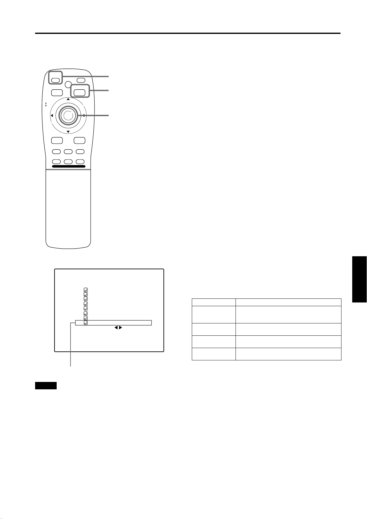
Setting Up (or Changing) the Display Size (Cont.)
Operating the Main Menu
■ Remote control unit
QUICK
ALIGN.
PRESET
LOCK UNLOCK
LENS
AV
UT
SHIFT ZOOM FOCUS
DW
AV HIDE
LENS
OPERATE
PAGE BACK
M
E
N
U
/
E
N
T
E
R
RGB/COMPUTER
+
–
■ Main menu
RGB1
PIXEL CLOCK
POSITION
PICTURE
OPTIONS
SOURCE
CHANNEL
USER SOURCE SET UP
DISPLAY SIZE
DECODER
LANGUAGE
QUICK ALIGN. button
PAGE BACK button
MENU/ENTER button
AUTO
SXGA1
AUTO( )
ENGLISH
Press QUICK ALIGN.
7
• The quick alignment automatic adjustment feature gets
activated. During the adjustment, “QUICK-
ALIGNMENT” (Quick-Alignment) is shown on the
screen.
After finishing step 7, press the MENU/
8
ENTER button.
• The main menu appears on the screen.
Press MENU/ENTER toward the 5 or ∞
9
mark to select “DISPLAY SIZE”.
• The selected item (text display) is shown in magenta
color.
Press the MENU/ENTER button.
10
• A submenu item, “DISPLAY SIZE adjustment menu”
appears on the screen.
Press MENU/ENTER toward the 5 or ∞
11
mark to select “H CENTER”, then press
MENU/ENTER button toward the 2 or
3 mark to set the horizontal position.
Press MENU/ENTER toward the 5 or ∞
12
mark to select “V CENTER”, then press
MENU/ENTER button toward the 2 or
3 mark to set the vertical position.
■ To return to the main menu, press PAGE
BACK. To finish the main menu, press
PAGE BACK again.
Adjustment item Contents of adjustment
H PIXEL Adjusts the number of horizontal effective
V PIXEL Adjusts the number of vertical effective dots.
H CENTER Adjusts the horizontal display position.
V CENTER Adjusts the horizontal display position.
dots.
Adjustment value (640j1360)
Adjustment value (350j1024)
Adjustment value (0j639)
Adjustment value (1j511)
ENGLISHDEUTSHFRANÇAISITALIANOESPAÑOL
Submenu item [DISPLAY SIZE]
Notes
• The selected item is shown in magenta color. Items shown
in gray color cannot be operated or set in the current mode.
• If the image becomes partially missing while “H CENTER”
or “V CENTER” is being set, perform this setting and the
position adjustment alternately.
Display size setting menu: Range of settings
57
Page 60

Filter Maintenance and Light-Source Lamp
Replacement
Cleaning and Replacing the Filter
The filters should be cleaned periodically. If they are heavily stained, do not become clean if cleaned, or are damaged,
replace them with new filters (Parts number: LC30505); otherwise, dirt and dust may get inside, possibly causing an adverse
effect on the screen and preventing you from enjoying clear pictures.
The projector has two filters installed, one on the right side and the other on the back.
■
Bring the projector into stand-by state, and turn off the MAIN POWER switch.
1
Put the projector into stand-by, and make sure the STAND BY indicator is lit, then tun off the MAIN POWER switch. After
that, disconnect the power cord from the wall outlet and the projector. For detailed procedures, refer to “Turning off the
power” (page 24).
Remove the filter cover screws.
2
Using a Phillips screwdriver, remove the six screws fixing each filter.
Two filters are used, one on the right side and the other on the back of the projector.
Note
• If the filter is clogged with dirt, etc., the projector
goes into an emergency mode (the EMERGENCY
indicator blinks).
• So, clean the filter periodically. For the emergency
mode, refer to pages 7 and 23.
Remove the filters.
3
To remove the filter, pinch the center portion of the filter with your fingers and pull it toward you.
(The filter is held by four tabs.)
There are two filters used.
58
(To be continued on the next page)
Page 61

Filter Maintenance and Light-Source Lamp Replacement
Cleaning and Replacing the Filter (Cont.)
Clean the filters.
4
Wash the filter in water with neutral detergent, and dry it in the shade.
Reinstall the filters.
5
To reinstall the filters to the projector, reverse the procedure for removing. Finally, be sure to reinstall the filter covers.
Notes
• Install the filters correctly; otherwise the projector will not operate normally.
• If the filters and/or filter holders are damaged, the projector may fail to operate. Then, replace with new parts.
CAUTION
• Put on rubber gloves when using neutral detergent.
• After you have washed the filter in water, make sure the filter is completely dry before reinstalling it. Otherwise,
electric shock or malfunction could occur.
• Do not clean the filter using a vacuum cleaner. Since the filter is soft, it may be sucked into the vacuum cleaner
or damaged.
About Light-Source Lamp Replacement
The light-source lamp has its service life. It is approximately 1000 hours.
When the light-source lamp approaches the end of its service life, its degradation progresses rapidly. When the lamp’s used
hours exceed 900 hours, the projector’s LAMP indicator comes on. Also, at the start of projection (lamp energized), the
message “REPL.-LAMP” appears on the projection screen for about two minutes. Then, the light-source lamp needs to be
replaced. When lamp’s service has reached 1000 hours, the projector’s LAMP indicator starts blinking. The specified lamp
replacement period is 1000 hours, but depending on use conditions, the replacement period may vary. If video image is dark
and its color tint is extraordinary even after you have adjusted color tint and brightness, replace the light-source lamp a little
earlier.
For replacing the light-source lamp, consult the dealer where you purchased your projector or a local service center.
ENGLISHDEUTSHFRANÇAISITALIANOESPAÑOL
59
Page 62

Troubleshooting
Solutions to common problems related to your projector are described here. If none of the solutions presented here solves the
problem, unplug the projector and consult a authorized dealer or service center.
Symptom Probable cause Corrective action Page
Power is not supplied. • Is the power cord disconnected? • Insert the power cord (plug) firmly. 22
• Is the main power switch turned on? • Turn on the MAIN POWER switch. 24
• Is the correct power voltage used? • Check that AC 200V ~ 240V is supplied. 3, 64
• Has the breaker tripped open? • Check that the breaker is closed. –
Light is not emitted, or
light level is low.
With power on,
operation starts but
stops in a few
minutes.
Video image does not
appear.
• Has the lamp protective function
activated? (This can occur if the power is
shut down due to a power failure, etc.)
• Is the lens cap removed? • Remove the lens cap. 22
• Is the lamp life near its end? • Check the lamp use time on the menu,
• Has the projector been moved from its
installed place?
• Is the air intake or exhaust area
blocked?
• Is the correct input selected? • Select the correct inputs with the AV and
• Are connected devices connected
correctly?
• Are signals being supplied from the
connected devices?
• Wait until the lamp has cooled down.
(Turn on the main power sand let the
fans cool the lamp.)
About 10 minutes later, press OPERATE
on the remote control.
40, 58
and if the lamp life is near its end,
arrange for a replacement lamp, or
replace a little earlier.
• Check the installed position. –
• Turn off the MAIN POWER switch,
remove any blocking objects, and turn on
the MAIN POWER switch again.
RGB buttons.
• Connect connected devices correctly. 19, 20
• Set connected devices correctly. –
7, 8, 15
25
–
• Are input signals (scanning frequency,
etc.) appropriate?
• Is the source setting correctly selected?
Isn’t a wrong source (forced mode)
selected?
Video image dims. • Is brightness adjusted correctly? • Adjust brightness on the menu. 37, 39
• Is focus adjusted correctly? • Adjust focus with the remote control’s
• Is distance too short or too long? • Set the projector at the correct distance. 17
Color is poor or
unstable.
During video replay,
video image
sometimes is
disturbed.
• Are TRACKING and PHASE adjusted
correctly?
• Is picture quality (color density, etc.)
adjusted correctly?
• Is the correct CLAMP selected? • Select the correct CLAMP on the
• have Installation adjustment been
performed?
• Check if the signal is correct as input
(scanning frequency, etc.).Input the
appropriate signal.
• Set the source setting to AUTO or to the
correct dedicated source (forced mode).
FOCUS (+/–) buttons.
• Adjust TRACKING and PHASE on the
menu.
• Adjust picture quality on the menu. 37, 39
OPTION MENU.
• For installation, consult the dealer where
you purchased the projector or a local
service center.
18
43, 45
26, 29
29, 35
40, 41
–
60
Page 63
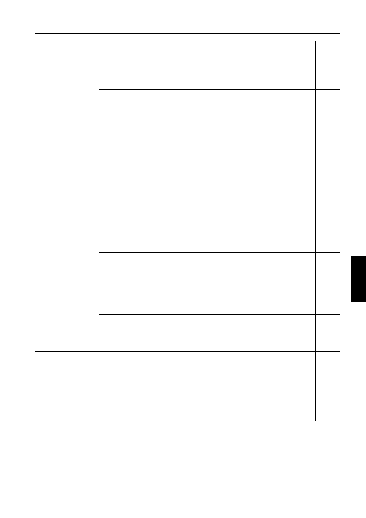
Troubleshooting
Symptom Probable cause Corrective action Page
Image color is poor or
image is disturbed.
Specific colors fail to
be displayed.
The upper part of the
video image bows or
distorts.
• Is picture quality (color density, etc.)
adjusted correctly?
• Is the correct broadcast system (color
system) selected?
• Are signals (scanning frequency, etc.) to
connected devices appropriate?
• Is the source setting correctly selected?
Isn’t a wrong source (forced mode)
selected?
• Are specifications of the signal being
input matching those of the video input
card?
• Is the input cable connected correctly? • Check cable connections. 20
• Has the lamp’s life come to its end? • Check the used lamp hours on the menu,
• While computer system signal is input,
isn’t a sync signal for composite sync
) or G on sync being input?
S
(C
• Adjust picture quality on the menu. 37, 39
• Set the broadcast system (color system)
to AUTO.
• Check if the signal is appropriate
(scanning frequency, etc.), and input the
appropriate signal.
• Set the source setting to AUTO. If the
problem still persists, set it to the correct
dedicated source (forced mode).
• Check specifications of both signal being
input and video input card.
and if the lamp life is near its end, consult
the dealer where you purchased the
projector or a local service center.
• Input separate sync signals for vertical
sync (V) and horizontal sync (H) signals.
43
33
18
~
–
59
9
45
The projection
position on the screen
has shifted.
Video image suddenly
go out.
Lens shift adjustment
is not possible.
• Isn’t signal with much jitter or skew
distortion being input to a video deck?
• Is the source setting correctly selected?
Isn’t a wrong source (forced mode)
selected?
• Have the channel’s setup contents been
changed?
• Have the channel’s setup contents been
changed?
• Is sync signal being input correctly? • Check sync signal and related
• Has the projector been moved from its
installed place?
• Aren’t video turned off by pressing the
remote control’s AV HIDE button?
• Are all color video signals being input? • Check signals and connections.
• Is the shift center lock pin for shipment
left attached?
• Input signals with little jitter or distortion. –
• Set the source setting to AUTO. If the
problem still persists, set it to the correct
dedicated source (forced mode).
• Check the setup contents been changed.
• Check the setup contents of the channel
and correct them if necessary.
connection.
• Check the installed position. –
• Press the remote control’s AV HIDE
button to turn video on.
• Remove the shift center lock pin, and
then make adjustments. (For how to
remove the shift center lock pin, consult
the dealer where you purchased the
projector or a local service center.)
43 ~ 45
46
50
~
50
46
~
9
11
18
22
~
15
ENGLISHDEUTSHFRANÇAISITALIANOESPAÑOL
61
Page 64

Troubleshooting
Symptom Probable cause Corrective action Page
Remote control unit
does not work.
• Are batteries installed correctly? • Match the polarities of batteries correctly
(+ to + and – to –).
• Are batteries exhausted? • Replace with new batteries. 12
• Is there a shielding object between the
remote control unit and the remote
sensor?
• Is the distance too long? • Use the remote control unit at a nearer
• Is the remote control’s LENS LOCK j
UNLOCK switch set to LOCK?
• Remove any shielding objects. –
point.
• Set the remote control’s LENS LOCK j
UNLOCK switch to UNLOCK?
■ When the emergency indicator starts blinking:
Refer to the CAUTION and NOTES on page 23.
* This projector is equipped with a microcomputer that may operate abnormally due to interference from external
components. If this happens, turn off the main power and disconnect the power cord from the wall AC outlet. Then
reconnect the power cord to AC outlet and turn on the main power again.
(For the turning on and off the power, see page 24.)
12
21
11
62
Page 65

Specifications
■
Optical mechanism system
• Projection method 3D-ILA device, 1 lens, 3 primary color optical shutter method
• D-ILA device 0.9" measured diagonally (1365 pixels × 1024 pixels) × 3 (Total number of pixels: 4,193,280)
• Projecting lens
(separately available)
• Screen size 60" to 300" [recommended] to 600" [maximum] measured diagonally (*with aspect ratio: 4 : 3)
• Light-source lamp 1.6 kW xenon lamp
■
Electrical system
• Color system NTSC, NTSC 4.43, PAL, SECAM (
• Resolution 1365 dots × 1024 dots (
• Scanning frequency Horizontal frequency : 15 kHz ~ 82 kHz
■
Input / output
[EXT. IN (AV IN input)]
• Y/C 1-line, mini-DIN 4 pin × 1 (
GL-M4023SZ 3:1~7:1 zoom lens
GL-M4015S 1.5:1 fixed focus lens
* Automatic switching / manual switching
*S-XGA full resolution, during RGB input
1000TV lines (
Vertical frequency : 48 Hz ~ 78 Hz
* The Y/C (S-video) and VIDEO (composite video) signals can be input with the video board
installed.
Y (luminance signal) : 1V(p-p), 75Ω (negative sync)
C (chroma signal) : 0.286V(p-p) (burst signal), 75Ω [NTSC]
*Horizontal resolution, aspect ratio 4 : 3, during video input
* With the video board, separately available, installed
0.3V(p-p) (burst signal), 75Ω [PAL]
)
)
)
)
• VIDEO 1-line, BNC × 1 (
Composite video signal : 1V(p-p), 75Ω (negative sync)
• Y, PB/B-Y, PR/R-Y 1-line, BNC × 3
Component (Y, B-Y, R-Y) signals
Y : 1V(p-p), 75Ω (negative sync or 3-value sync)
P
/B-Y : 0.7V(p-p), 75Ω
B
P
/R-Y : 0.7V(p-p), 75Ω
R
[RGB IN (RGB input)]
• RGB IN-1 (PC) 1-line, D-sub 3-row 15 pin × 1
Analog RGB signal
R : 0.7V(p-p), 75Ω
B : 0.7V(p-p), 75Ω
G : 0.7V(p-p), 75Ω
G on Sync : 1V(p-p), 75Ω (negative sync)
Sync signal : 1V(p-p) to 5V(p-p), high impedance (positive/negative polarity)
* Some connected devices may not correspond to composite sync (CS) or G on sync signal.
• RGB IN-2
1-line, BNC × 5
Analog RGB signal
R : 0.7V(p-p), 75Ω
B : 0.7V(p-p), 75Ω
G : 0.7V(p-p), 75Ω
G on Sync : 1V(p-p), 75Ω (negative sync)
* With the video board, separately available, installed
)
ENGLISHDEUTSHFRANÇAISITALIANOESPAÑOL
63
Page 66

Specifications
Horizontal sync/composite sync signal (H/CS)
H : 1V(p-p) to 5V(p-p), high impedance (positive/negative polarity)
C
S
Vertical sync signal (V)
V : 1V(p-p) to 5V(p-p), high impedance (positive/negative polarity)
* Some connected devices may not correspond to composite sync (CS) or G on sync signal.
[RGB OUT (RGB OUTPUT)]
• RGB OUT 1-line, D-sub 3-row 15-pin × 1
Analog RGB signal
R : 0.7V(p-p), 75Ω
B : 0.7V(p-p), 75Ω
G : 0.7V(p-p), 75Ω
G on sync : 1V(p-p), 75Ω (negative sync)
Horizontal sync/composite sync signal (H/C
H : TTL level (Polarity: Same for input)
C
S
Vertical sync signal (V)
V : TTL level (Polarity: Same for input)
[CONTROL]
• RS-232C: 1-line, D-sub 9-pin × 1
* RS-232C-interface specified control terminal for controlling this projector with a personal
computer.
• REMOTE 1-line, mini-jack × 1
: 1V(p-p) to 5V(p-p), high impedance (positive/negative polarity)
: TTL level (Polarity: Same for input)
)
S
■ General
• Power requirements AC 200 V ~ 240 V, 50 Hz/60 Hz
• Power consumption 12 A (at 220 V)
• Allowable operation temperature + 5°C to + 40°C
• Allowable relative humidity 90% or less (no condensation)
• Allowable storage temperature – 5°C to + 60°C
• Maximum outside dimensions Approx. (W)747 mm × (H)420 mm × (D)793 mm
(excluding protruding parts)
• Weight Approx. 71kg
• Accessories (Refer to page 4.)
* Design and specifications are subject to change without notice.
* D-ILA devices are manufactured with a very high-precision technology, allowing 99.99% of the pixels to be effective. Only
0.01% or less of the pixels are missing or always on.
* For easy understanding, pictures and illustrations are shown by being emphasized, omitted or composed, and may be more
or less different from actual products.
* TRADEMARKS
IBM,IBM PC, and VGA are registered trademarks of International Business Machines Corporation. Macintosh is registered
trademarks of Apple Computer, Inc.
VESA is a trademark of the non-profit organization Video Electronics Standard Association.
All other product names mentioned herein are used for identification purposes only, and may be the trademarks or
registered trademarks of their respective companies.
64
Page 67

Outside dimensions
■ Top
687
747
30
688
30
Specifications
Unit: mm
■ Front ■ Side
720
42
18
368
~
420
50
φ
600
30
793
688
Y/C VIDEO
RGB
RGB IN-1
RGB IN-2
EXT. IN
R
GH/CS
BV PR/R-Y
REMOTE
RGB OUT
RS-232C
42
18
Y
B/B-Y
P
CONTROL
30
■ DTV-format signals
* The following are DTV-format signals that can be input.
DTV-Formats 480i 480p 720p 1080i 1080 24sF
Signal Standard ITU-R BT. 601-4 SMPTE 293M SMPTE 296M SMPTE 274M SMPTE 274M
Scanning Line /
Frame
Effective Samples
× Scanning Lines
Field Frequency (Hz) 59.94 59.94 60/59.94 60/59.94 48
Line Frequency (Hz) 15734 31468.5 45000/44955 33750/33716.25 27000
Interlace Ratio 0.5 1 1 0.5 sF
525 525 750 1125 1125
720 × 485 720 × 483 1280 × 720 1920 × 1080 1920 × 1080
59
230
ENGLISHDEUTSHFRANÇAISITALIANOESPAÑOL
59
65
Page 68

Specifications
Pin assignment (Specifications for terminals)
■ Y/C terminal
Pin number Signal name
4
2
■ RS-232C terminal
6
7
8
9
3
1
1
2
3
4
5
1 GND (Y)
2GND (C)
3Y
4C
Pin number Signal name Pin number Signal name
1 N/C 6 N/C
2RD 7N/C
3TD 8N/C
4 N/C 9 N/C
5GND
■ COMPUTER IN-1 (PC) / COMPUTER OUT terminal
Pin number Signal name Pin number Signal name
1Red 9N/C
2 Green 10 GND (SYNC)
3Blue 11GND
4N/C 12N/C
5 N/C 13 H.SYNC
6 GND (Red) 14 V.SYNC
7 GND (Green) 15 N/C
8GND (Blue)
15
14
13
12
11
5
4
3
2
1
10
9
8
7
6
Information on separately sold items
• Projection lens
GL-M4023SZ
GL-M4015S
• Video board
PK-G1101D A board to be used for adding composite video signal input and Y/C (S-Video)
3 : 1~7 : 1 zoom lens
1.5 : 1 fixed-focus lens
function to the projector.
66
Page 69

Merci d’avoir acheté ce projecteur. Avant de l’utiliser, lisez et respectez attentivement toutes les instructions pour profiter au
maximum des capacités du projecteur.
IMPORTANTES MESURES DE SÉCURITÉ
INFORMATIONS IMPORTANTES
IMPORTANTES MESURES
DE SÉCURITÉ
AVERTISSEMENT :
POUR ÉVITER TOUT RISQUE D’INCENDIE OU
D’ÉLÉCTROCUTION, N’EXPOSEZ PAS CET
APPAREIL À LA PLUIE OU À L’HUMIDITÉ.
AVERTISSEMENT :
CET APPAREIL DOIT ETRE MIS A LA TERRE.
ATTENTION :
Pour réduire les risques d’électrocution, ne retirez pas
le couvercle de l’appareil.
Référez-vous à un technicien qualifié.
INFORMATION SUR LE BRUIT
MACHINE (Allemagne uniquementy)
Modification de l’arrêté n°3 sur le bruit machine.
GSGV, 18 janvier 1991: Le niveau de pression
accoustique à l’emplacement de l’utilisateur est
inférieur ou égal à 70 dB(A) conformément à ISO
7779.
À propos de la brûlure du dispositif D-ILA
Ne projetez pas la même image fixe pendant longtemps non
plus qu’une image vidéo anormalement brillante.
Ne projetez pas d’images vidéo avec une intensité ou un
contraste élevé sur un écran. L’image vidéo pourrait brûler le
dispositif D-ILA.
Faites particulièrement attention lors de la projection d’images
de jeux vidéo de programmes informatiques. Il n’y a pas de
problème avec les images de lecture de cassettes vidéo.
AVERTISSEMENT
Ceci est un produit de Classe A. Dans un
environnement domestique, ce produit peut provoquer
des interférences radio, auquel cas l’utilisateur devra
prendre des mesures adéquates.
L’énergie électrique peut remplir beaucoup de fonctions
utiles. Cet appareil a été conçu et fabriqué pour assurer
votre propre sécurité. Mais UNE UTILISATION
INCORRECTE PEUT ENTRAÎNER UN RISQUE
POTENTIEL D’ÉLECTROCUTION OU D’INCENDIE. Afin
de ne pas annuler les dispositifs de sécurité incorporés dans
cet appareil, observez les règles fondamentales suivantes
pour son installation, son utilisation et sa réparation. Veuillez
lire attentivement ces “Importantes mesures de sécurité”
avant d’utiliser l’appareil.
– Toutes les instructions de sécurité et de fonctionnement
– Les instructions de sécurité et de fonctionnement doivent
– Tous les avertissements sur l’appareil et dans le mode
– Toutes les instructions d’utilisation doivent être suivies.
– Débranchez cet appareil de la prise murale avant de le
– N’utilisez pas d’accessoires non recommandés par le
– N’utilisez pas ce produit près de l’eau. Ne pas l’utiliser
– Ne placez pas cet appareil sur un chariot, une table ou tout
– Quand vous utilisez cet appareil sur un
– Les fentes et les ouvertures du coffret sont nécessaires
doivent être lues avant l’utilisation de l’appareil.
être conservées à titre d’information.
d’emploi doivent être respectés.
nettoyer. Ne pas utiliser de nettoyant liquide ou en
aérosol. Utilisez un chiffon humide pour le nettoyage.
fabricant de l’appareil car ils pourraient être dangereux.
non plus après l’avoir déplacé d’une basse température à
une température élevée. Cela produit une condensation
d’humidité qui peut entraîner un incendie, une
électrocution ou d’autres dangers.
autre support instable. L’appareil pourrait tomber, et ainsi
blesser gravement un enfant ou un adulte, ainsi qu’être luimême sérieusement endommagé. L’appareil doit être
monté conformément aux instructions du fabricant et doit
utiliser un support recommandé par le fabricant.
chariot, évitez les arrêts brusques,
l’utilisation de force excessive et les
surfaces accidentées qui pourraient
causer un renversement de l’appareil et du
chariot, risquant d’endommager l’appareil
ou de blesser l’utilisateur.
pour la ventilation. Elles assurent un fonctionnement sûr
de l’appareil et le protège d’une surchauffe. Ces
ouvertures ne doivent pas être bloquées ou recouvertes.
(Les ouvertures ne doivent jamais être bloquées en
plaçant l’appareil sur un lit, un divan, un tapis ou une
surface similaire. Il ne doit pas être encastré dans un
emplacement comme une bibliothèque ou un bâti sauf si
une ventilation correcte existe et si les instructions du
fabricant ont été respectées.)
Pour une ventilation correcte, séparez cet appareil de
tout autre appareil pouvant empêcher sa ventilation ;
conservez un espacement,entre appareils, de plus de
60 cm.
ENGLISHFRANÇAISFRANÇAISITALIANOESPAÑOL
1
Page 70

– Cet appareil doit être alimenté uniquement avec le type
d’alimentation indiqué sur l’étiquette. Si vous n’êtes pas
sûr du type d’alimentation secteur de votre maison,
consultez le revendeur de l’appareil ou votre compagnie
d’électricité.
– Cet appareil est équipé d’une fiche à trois broches. Elle
ne peut être branchée que dans une prise secteur avec
mise à la terre. Si vous ne pouvez pas insérer la fiche
dans la prise, contactez votre électricien afin qu’il installe
une prise correcte. N’essayez pas de défaire le principe
de sécurité de la fiche avec mise à la terre.
– Les cordons d’alimentation doivent être positionnés de
façon à ce qu’ils ne soient pas écrasés ou coincés par
des objets placés sous ou contre eux. Faites
particulièrement attention aux cordons au niveau des
portes, des fiches et prises ainsi qu’au niveau de la sortie
de l’appareil.
– Pour une meilleure protection pendant un orage ou
quand il est laissé sans surveillance ou n’est pas utilisé
pendant une longue période de temps, débranchez-le de
la prise secteur murale et déconnectez le système de
câbles. Cela évitera qu’il soit endommagé du fait d’un
éclair ou d’une surtension.
– Ne surchargez pas les prises murales, les cordons
prolongateurs ou les prises de courant sur les autres
appareils car cela pourrait entraîner un risque d’incendie
ou d’électrocution.
– Ne jamais insérer d’objet d’aucune sorte à l’intérieur de
cet appareil à travers les ouvertures car ils pourraient
toucher des points de tension dangereux ou créer un
court-circuit qui pourrait entraîner un incendie ou une
électrocution. Ne jamais renverser de liquide d’aucune
sorte sur l’appareil.
– N’essayez pas de réparer cet appareil vous-même car
l’ouvrir ou retirer les couvercles peut vous exposer à des
tensions dangereuses ou à d’autres dangers. Référez-
vous à un personnel qualifié pour toute réparation.
– Débranchez l’appareil de la prise secteur murale et
contactez un réparateur qualifié dans les conditions
suivantes :
a) Quand le cordon ou la fiche d’alimentation secteur est
endommagé.
b) Si un liquide a coulé ou si un objet est tombé sur
l’appareil.
c) Si l’appareil a été exposé à la pluie ou à l’eau.
d) Si l’appareil ne fonctionne pas normalement en
suivant les instructions d’utilisation. Ajustez
uniquement les commandes couvertes par le mode
d’emploi, car un ajustement incorrect des
commandes peut endommager l’appareil et
demandera souvent beaucoup de temps à un
technicien qualifié pour ramener l’appareil en état de
fonctionnement normal.
e) Si le produit est tombé ou a été endommagé de
n’importe quelle autre façon.
f) Quand l’appareil montre un changement évident dans
ses performances, cela indique qu’il doit être réparé.
– Quand le remplacement des pièces est nécessaire,
assurez-vous que le réparateur a utilisé les pièces de
rechange spécifiées par le fabricant ou possédant les
mêmes caractéristiques que la pièce originale. Un
remplacement non autorisé peut entraîner in incendie,
une électrocution ou autres dangers.
– Après que cet appareil a subi une réparation ou un
entretien, demandez au réparateur de réaliser les
vérifications de sécurité pour déterminer si l’appareil est
en état de fonctionnement correct.
– L’appareil doit être placé à plus de trente centimètres de
sources de chaleur, comme un radiateur, un
accumulateur de chaleur, un fourneau ou tout autre
appareil (amplificateurs inclus) produisant de la chaleur.
– Lors d’un raccordement avec un magnétoscope ou un
ordinateur personnel, vous devez mettre cet appareil
hors tension pour éviter tout choc électrique.
– Ne placez pas de produits combustibles derrière le
ventilateur de refroidissement. Par exemple, du tissu, du
papier, des allumettes, une bombe aérosol ou un briquet
à gaz qui présentent des dangers particuliers s’ils sont
chauffés.
– Ne regardez pas dans l’objectif de projection quand la
lampe du projecteur est allumée. Une exposition des
yeux à une forte lumière peut affaiblir votre vue.
– Ne regardez pas à l’intérieur de l’appareil au travers des
évents (orifices de ventilation), etc. Ne regardez pas
directement la lampe de projection en ouvrant le coffret
pendant que celle-ci est allumée. La lampe de projection
émet aussi des rayons ultraviolets et la lumière est si
forte que votre vue pourrait être affaiblie.
– Du gaz xénon est contenu sous haute pression à
l’intérieur de la lampe (module lampe) de ce projecteur.
Si vous la faites tomber, la heurtez ou la jetez, il y aura
risque d’explosion et vous pourriez vous blesser. Faites
très attention lors de la manipulation de la lampe. S’il y a
quelque chose que vous ne comprenez pas, contactez
votre revendeur.
– Utilisez uniquement le cordon fourni conçu pour cet
appareil afin d’éviter tout choc électrique.
La tension d’alimentation secteur de cet appareil est de
200 V ~ 240 V CA ;le cordon d’alimentation fourni est
conforme à la tension suivante. N’utilisez que le cordon
d’alimentation désigné par nos revendeurs pour la
sécurité et la compatibilité électromagnétique (EMC).
Si l’appareil est utilisé avec une tension d’alimentation
secteur différente, le cordon d’alimentation doit être
changé.
Consultez votre revendeur.
* NE LAISSEZ PAS une personne non
qualifiée installer l’appareil.
Demandez à votre revendeur d’installer l’appareil (par
exemple au plafond) car cela exige des connaissances
et techniques spéciales.
Si l’installation est réalisée par une personne non
qualifiée, cela pourrait entraîner des blessures
personnelles ou une électrocution.
2
Page 71

CONNEXION ELECTRIQUE
(Royaume-Uni seulement)
AVERTISSEMENT
Ne débranchez pas la fiche principale de cet appareil.
Si la fiche existante ne convient pas aux prises de courant
de votre maison ou si le cordon est trop court pour atteindre
une prise de courant, procurez-vous un cordon prolongateur
ou un adapteur de sécurité approuvé ou consultez votre
revendeur.
Si la fiche secteur etait coupée, retirez le fusible et jetez la
prise immédiatement, pour éviter tout danger d’électrocution
par une connexion accidentelle à l’alimentation secteur.
Si la nouvelle fiche secteur doit être adapté, suivez les
instructions données ci-dessous:
AVERTISSEMENT:
CET APPAREIL DOIT ETRE MIS A LA TERRE.
IMPORTANT:
Les codes couleurs des fils du cordon d’alimentation de cet
appareil sont les suivants:
Vert et jaune: Terre
Bleu: Neutre
Marron: Sous tension
Le fil coloré en vert et jaune doit être connecté à la borne
marquée ˙ par la lettre E ou le symbole de terre ou de
couleur vert et jaune.
Le fil qui est coloré en bleu doit être connecté à la borne qui
est marqué par la lettre N ou de couleur noire.
Le fil qui est coloré en marron doit être connecté à la borne
qui est marquée de la lettre L ou de couleur rouge.
Lors du remplacement du fusible, assurez-vous d’utiliser
seulement un fusible de valeur correcte et de type approuvé.
Remettez en place le couvercle du fusible.
EN CAS DE DOUTE —— CONSULTEZ UN ELECTRICIEN
QUALIFIE.
Comme ces couleurs ne correspondent peut être pas avec
les couleurs identifiant les bornes de votre fiche. Procédez
comme suit:
Informations relatives à la prise du cordon
d’alimentation
Le cordon d’alimentation de ce projecteur n’est pas
équipé d’une prise. Nous vous recommandons de
sélectionner et de raccorder une prise adaptée à votre
prise de courant.
Utilisez une prise 250V/20A.
Pour votre protection, les extrémités du cordon
d’alimentation sont recouvertes.
Retirez ces protections avant de raccorder la prise au
cordon d’alimentation.
ENGLISHFRANÇAISFRANÇAISITALIANOESPAÑOL
3
Page 72

Table des matières
IMPORTANTES MESURES DE
SÉCURITÉ ........................................ 1
Table des matières .......................... 4
Accessoires ..................................... 4
Commandes et fonctions................ 5
Face avant / Dessus / Côté droit.............................5
Côté gauche / Arrière ..............................................6
Panneau de commande ..........................................7
Panneau de connecteurs ........................................9
Télécommande .....................................................10
Touche MENU/ENTER
(Fonctionnement du menu) ...................................12
Mise en place des piles.........................................12
Installation du projecteur.............. 13
Précautions pour l’installation ...............................13
Fonction de déplacement d’objectif.......................15
Distances de projection et tailles d’écran..............17
Raccordement avec différents
appareils......................................... 18
Signaux pouvant être entrés dans le projecteur....18
Exemples de configuration système .....................19
Raccordement aux ordinateurs.............................20
Raccordement à des appareils qui contrôle le
projecteur ..............................................................21
Branchement du cordon d’alimentation (fourni) ....22
Lors de la mise en marche des périphériques
raccordés au projecteur ........................................23
Fonctionnement de base .............. 24
1. Mettre sous tension...........................................24
2. Sélection de l’entrée vidéo à projeter................25
3. Réglage de la taille de l’écran...........................25
4. Réglage de la mise au point..............................26
Autres fonctions ....................................................26
Utilisation du menu de réglage .... 29
Réglages de base .................................................29
Utilisation du menu principal........ 30
Configuration du menu principal (Entrée AV)....... 30
Configuration du menu principal
(entrée d’ordinateur)............................................. 31
Utilisation du menu principal
(Utilisation de base du menu principal) ................ 32
Changement du système de couleur.................... 33
Changement de l’affichage de la langue.............. 34
Ajustement de l’horloge de pixels......................... 35
Réglage de la position de l’écran......................... 36
Ajustement de la qualité de l’image...................... 37
Réglage et ajustement d’autres fonctions
(OPTIONS)........................................................... 40
Modification (définition) de la source.................... 43
Configuration des canaux..................................... 46
Configuration des canaux
(configuration de LINE) ........................................ 47
Configuration des canaux
(configuration de SOURCE) ................................. 48
Configuration des canaux
(configuration de SW No) ..................................... 50
Changement de canal (Changement de CH)....... 51
Configuration (ou modification) des sources
utilisateur.............................................................. 53
Configuration (ou modification) de la taille
d’affichage............................................................ 56
Maintenance du filtre et
remplacement de la lampe source de
lumière ............................................58
Nettoyage et remplacement du filtre .................... 58
A propos du remplacement de la lampe source de
lumière.................................................................. 59
Dépannage...................................... 60
Spécifications................................. 63
Dimensions extérieures........................................ 65
Affectation des broches
(Spécification pour les prises) .............................. 66
Accessoires
Les accessoires suivants sont fournis avec le projecteur. Vérifiez s’ils sont bien tous présents. Si l’un de ces
accessoires manquait, veuillez contacter votre revendeur.
Télécommande
(RM-M4000G)
4
Piles sèches AA/R6 (×2)
(pour vérifier le fonctionnement)
Cordon d’alimentation
[environ 3,35 m]
Cordon de télécommande
[environ 15 m]
Page 73

Commandes et fonctions
Face avant / Dessus / Côté droit
1 Pied réglable
Il est réglé sur la position la plus basse en sortie d’usine.
Tourner le pied pour mettre le projecteur de niveau. Le
réglage peut être effectué sur une plage de ±4° à partir de
la position verticale et ±5° à partir de la position
horizontale.
2 Panneau de commande
Pour plus de détails, référez-vous à “Panneau de
connecteurs” à la page 9.
3 Zone d’entrée d’air (filtre)
L’air passe au travers de cette zone pour refroidir la
lampe. Si cette zone est bloquée ou si quelque chose
empêche l’entrée ou la sortie de l’air, une surchauffe
interne peut se produire avec un risque d’incendie. Pour
plus de détails, référez-vous à “Précautions pour
l’installation” à la page 13.
PRECAUTIONS
• Faire attention car tout papier, tissu ou coussin léger se
trouvant près de l’appareil peut être aspiré. Ne pas bloquer
la zone d’entrée d’air. Une surchauffe pourrait se produire
avec un risque d’incendie.
• Nettoyer le filtre périodiquement. Pour plus de détails,
référez-vous à “Nettoyage et remplacement du filtre” à la
page 58.
Une couche de poussière sur le filtre peut être la cause
d’une surchauffe interne, avec un risque d’incendie ou de
mauvais fonctionnement de l’appareil.
4 Prise AC IN d’entrée d’alimentation
C’est la prise d’entrée d’alimentation où le cordon
d’alimentation est connecté. Pour plus de détails, référezvous à page 22.
5 Commutateur MAIN POWER
C’est l’interrupteur d’alimentation principal Lorsque le
projecteur est mis sous tension, il se met en mode
d’attente et le témoin STAND BY sur le panneau de
commande s’allume.
ON [ ❘❘❘❘ ] : L’appareil est mis sous tension.
OFF [{] :L’appareil est mis hors tension.
6 Capteur de télécommande
Lors de l’utilisation de la télécommande, la diriger vers ce
capteur. Il existe un autre capteur de télécommande à
l’arrière de l’appareil. La distance de fonctionnement
effective de la télécommande est de 10 m à partir de
chacun des capteurs. La plage de fonctionnement
effective des angles est de 50° à droite et à gauche, et de
15° vers le haut et vers le bas.
7 Support d’objectif
Fixez un objectif de projection (vendu séparément) à ce
support.
GL-M4023SZ Objectif zoom 3 : 1~7 : 1
GL-M4015S Objectif à mise au point fixe 1,5 : 1
Pour plus d’informations sur la fixation de l’objectif,
consulter le revendeur ou le centre de service ayant
effectué l’installation et les réglages de votre projecteur.
ENGLISHFRANÇAISFRANÇAISITALIANOESPAÑOL
5
Page 74

Commandes et fonctions
Côté gauche / Arrière
8 Évents de sortie d’air
Orifices permettant l’évacuation de l’air chaud et le
refroidissement des ventilateurs.
9 Panneau de commande
Pour plus de détails, référez-vous à “Panneau de
commande” à la page 7 et 8.
p Capteur de télécommande
Lors de l’utilisation de la télécommande, la diriger vers ce
capteur. Il existe un autre capteur de télécommande à
l’avant de l’appareil. La distance de fonctionnement
effective de la télécommande est de 10 m à partir de
chacun des capteurs. La plage de fonctionnement
effective des angles est de 50° à droite et à gauche, et de
15° vers le haut et vers le bas.
q Évents de sortie d’air (pour l’alimentation de la lampe)
L’air chaud du ventilateur de refroidissement de
l’alimentation de la lampe est évacué par cet orifice. Ce
ventilateur continue de tourner tant que le commutateur
MAIN POWER est allumé.
6
Page 75

Panneau de commande
Commandes et fonctions
STAND BY
1 Indicateur STAND BY
ON : Quand l’appareil est en mode d’attente.
Clignotant :Quand l’appareil est en mode de
refroidissement.
PRECAUTIONS
• Le mode de refroidissement continue pendant environ 20
secondes, pendant lesquelles la projection ne peut pas être
redémarrée. Une fois la période de refroidissement
terminée, le projecteur passe en mode d’attente, mais les
ventilateurs de refroidissement continuent de tourner
pendant environ 10 minutes (sauf le ventilateur de
refroidissement de l’alimentation de la lampe, qui continue
de tourner tant que le commutateur MAIN POWER est
allumé).
• Le but du mode de refroidissement est d’éviter aux pièces
intérieures d’être déformées ou cassées par la chaleur de
la lampe, de même que de prolonger la vie de la lampe. Ne
pas mettre l’appareil hors tension pendant le mode de
refroidissement. Ne pas bloquer les orifices d’évacuation
d’air lorsque l’appareil est en mode de refroidissement.
2 Indicateur OPERATE
ON : Quand le projecteur fonctionne (pendant la
projection)
3 Touche OPERATE
Lorsque le projecteur est en mode d’attente, appuyez sur
cette touche pendant une seconde ou plus. L’interrupteur
d’alimentation est allumé et l’indicateur OPERATE
s’allume. Appuyez sur cette touche une deuxième fois et
le projecteur se met en mode de refroidissement puis en
mode d’attente.
Mémo
Quand le projecteur est en mode de refroidissement :
Si vous appuyez sur la touche OPERATE, le projecteur n’est
pas mis sous tension.
4 Indicateur de lampe
ON : Àprès que la lampe a été utilisée plus de 900
heures.
Clignotant :
5 Indicateur TEMP
ON : La température intérieure du projecteur s’est
Remplacez la lampe. (Demandez au
fournisseur qui vous a vendu le projecteur de
remplacer la lampe.)
anormalement élevée.
OPERATE
LAMP
TEMP
EMERGENCY
AV RGB
Remarque
• Lorsque l’indicateur TEMP est allumé (en cas de
température anormale), l’alimentation est automatiquement
coupée et le projecteur passe en mode d’alerte (l’indicateur
EMERGENCY clignote).
6 Indicateur EMERGENCY
Clignotant :Un événement anormal s’est produit.
Mémo
À propos du mode d’alerte :
Le mode d’alerte est activé lorsque les anomalies suivantes
se sont produites (l’indicateur EMERGENCY clignote). En
mode d’alerte, la projection est automatiquement
interrompue et les ventilateurs de refroidissement tournent
pendant environ 10 minutes (sauf le ventilateur de
refroidissement de l’alimentation de la lampe, qui continue
de tourner tant que le commutateur MAIN POWER est
allumé).
• Lorsque la lampe s’éteint subitement.
• Lorsque les ventilateurs s’arrêtent.
• Lorsque la température interne est anormalement
élevée.
PRECAUTION
• Lorsque le projecteur est en mode d’alerte :
Une fois les ventilateurs de refroidissement arrêtés (sauf
celui de l’alimentation de la lampe), fermez l’interrupteur
d’alimentation et débranchez le cordon d’alimentation de la
prise de courant.
Vérifiez que les couvercles des filtres sont bien en place.
Rebranchez ensuite le cordon d’alimentation et essayez de
faire fonctionner le projecteur.
S’il repasse en mode d’alerte, après l’arrêt des ventilateurs
de refroidissement, fermez l’interrupteur d’alimentation,
débranchez le cordon d’alimentation et appelez le
revendeur pour une réparation.
SETTING
QUICK
ALIGN.
ENGLISHFRANÇAISFRANÇAISITALIANOESPAÑOL
7
Page 76
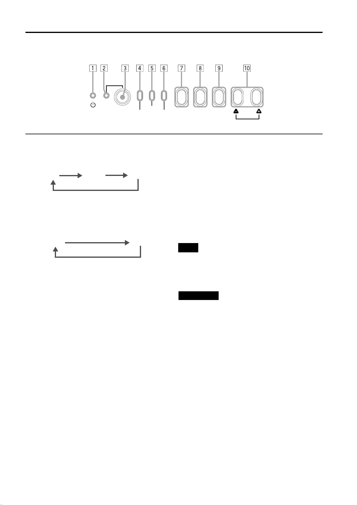
Commandes et fonctions
Panneau de commande (suite)
STAND BY
OPERATE
LAMP
TEMP
7 Touche AV
Utilisez cette touche pour sélectionner un appareil comme
un équipement vidéo raccordé à la prise EXT. IN du
projecteur. À chaque pression sur cette touche, l’appareil
sélectionné change comme suit :
Y/C*
VIDEO*
YPBPR
* Y/C et VIDEO ne peuvent être utilisés que lorsqu’une
carte vidéo vendue séparément a été installée.
8 Touche RGB
Utilisez cette touche pour sélectionner un appareil
raccordé aux prises RGB -1 ou -2. À chaque pression sur
cette touche, la sélection change comme suit :
RGB 1
RGB 2
9 Touche REGLAGE
Utilisez cette touche pour appeler le menu de réglage.
Pour plus de détails, référez-vous à “Réglages de base” à
la page 29.
EMERGENCY
AV RGB
SETTING
QUICK
ALIGN.
p Touche QUICK ALIGN. (Alignement rapide)
Lors de l’affichage d’un écran de menu, utilisez cette
touche pour ajuster les valeurs de l’élément sélectionné.
Lorsqu’aucun menu n’est affiché, la fonction d’alignement
rapide est appliquée.
Lorsqu’un menu est affiché
Touche ++++ :La valeur de l’élément sélectionné augmente.
Touche ---- :La valeur de l’élément sélectionné diminue.
Lorsqu’aucun menu n’est affiché
Appuyez sur les boutons ++++ et ---- simultanément :
“QUICK-ALIGNMENT” (Alignement rapide) est affiché à
l’écran et la fonction d’alignement rapide est appliquée
(TRACK, PHASE, POSITION H. et POSITION V. sont
ajustés automatiquement). Une fois l’ajustement terminé,
l’affichage disparaît automatiquement.
Mémo
La fonction d’alignement rapide :
• Fonctionne pour les signaux d’entrée d’ordinateur (prises
d’entrée RGB- 1 et - 2).
• Ne fonctionne pas pour les signaux d’entrée vidéo (prise
d’entrée EXT. IN.).
PRECAUTION
• L’ajustement automatique avec la fonction d’alignement
rapide doit être effectué sur un écran à image fixe et
brillante. Cette fonction risque de ne pas fonctionner
correctement sur un écran sombre ou en mouvement. Si
l’ajustement avec cette fonction se révèle insatisfaisant,
ajustez TRACK, PHASE, POSITION H. et POSITION V.
manuellement (voir pages 29, 35 et 36).
8
Page 77
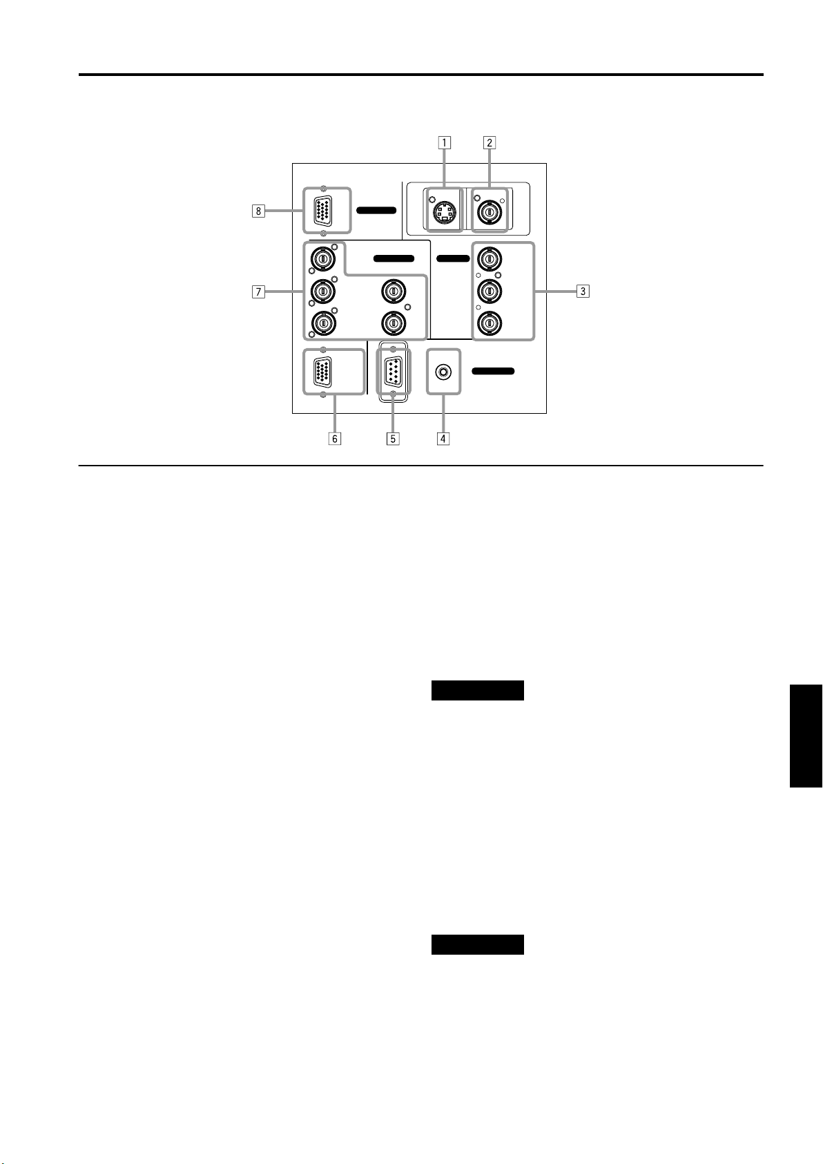
Panneau de connecteurs
RGB
Commandes et fonctions
Y/C VIDEO
RGB IN-1
RGB IN-2
R
GH/CS
BV PR/R-Y
RGB OUT
1 Prise d’entrée Y/C (S-vidéo) (Mini DIN 4 broches)
Raccordez cette prise à la prise de sortie S-Vidéo d’un
magnétoscope, etc.
* Cette prise peut être utilisée si une carte vidéo (PK-
G1101D) vendue séparément a été installée. La prise
n’est pas fournie lors de l’expédition du projecteur
depuis l’usine.
2 Prise d’entrée VIDEO (vidéo composite) (BNC)
Raccordez cette prise à la prise de sortie vidéo d’un
magnétoscope, etc.
* Cette prise peut être utilisée si une carte vidéo (PK-
G1101D) vendue séparément a été installée. La prise
n’est pas fournie lors de l’expédition du projecteur
depuis l’usine.
3 Prises d’entrée Y, PB/B-Y, PR/R-Y (BNC)
Ces prises d’entrée sont destinées aux signaux de
composante (Y, B-Y, R-Y) ou aux signaux de format DTV
(Y, P
, PR).
B
Les appareils dotés de prises de sortie de signal de
composante, tels que pour les formats DTV et NTSC,
peuvent y être raccordés.
* Pour plus de détails sur les signaux de format DTV
(480i, 480p, 720p, 1080i) compatibles avec cet appareil,
référez-vous à 65.
4 Prise REMOTE (mini jack)
Cette prise est utilisée pour relier la télécommande
directement au projecteur. Utilisez le câble de
télécommande fourni.
Une unité d’extension de télécommande infrarouge peut
aussi être raccordée à la prise jack.
5 Prise RS-232C (D-sub 9 broches)
C’est une prise d’interface RS-232C spécifique. Ce
projecteur peut être contrôlé par un ordinateur raccordé
en externe.
6 Prise RGB OUT (sortie RGB) (D-sub 3-rangées 15
broches)
Le signal d’entrée d’ordinateur projeté à l’écran est sorti à
cet endroit.
Une unité d’affichage peut être raccordée à cette prise.
EXT. IN
REMOTE
RS-232C
CONTROL
Y
P
B/B-Y
7 Prise RGB IN (entrée RGB) -2 (BNC)
Ce sont des prises d’entrée pour les signaux RGB
analogiques, les signaux
de synchronisation verticale (V), et les signaux de
synchronisation horizontale (H) / signaux composites
). Les appareils possédant des bornes de sortie de
S
(C
signal analogique RVB peuvent être raccordés.
*L’entrée des signaux de synchronisation externe est
automatiquement détectée.
La détection des signaux H/V ou CS provoque une
commutation
automatique sur synchronisation extérieure. L’ordre de
.
priorité est H/V > C
S
PRECAUTION
• Lorsque les signaux venant de l’ordinateur relié sont
entrés, le bord supérieur de l’écran peut apparaître courbé
si les signaux de synchronisation entrés sont composite
) ou sur G. Dans ce cas, utilisez des signaux de
S
(C
synchronisation séparés pour les synchronisations
horizontale (H) et verticale (H).
8 Prise RGB IN (sortie RGB) –1 (D-sub 3-rangées 15
broches)
C’est une prise d’entrée (PC) dédiée aux signaux venant
de l’ordinateur (signaux vidéo RVB et de synchronisation).
Raccordez la borne de sortie du moniteur de l’ordinateur à
cette prise. Lorsqu’un ordinateur Macintosh ou PC-9801/
9802 doit être relié, utilisez un adaptateur de conversion
disponible séparément.
PRECAUTION
• Lorsque les signaux venant de l’ordinateur relié sont
entrés, le bord supérieur de l’écran peut apparaître courbé
si les signaux de synchronisation entrés sont composite
(CS) ou sur G. Dans ce cas, utilisez des signaux de
synchronisation séparés pour les synchronisations
horizontale (H) et verticale (H).
ENGLISHFRANÇAISFRANÇAISITALIANOESPAÑOL
9
Page 78

Commandes et fonctions
Télécommande
LOCK UNLOCK
LENS
QUICK
ALIGN.
PRESET
OPERATE
AV HIDE
PAGE BACK
M
E
N
U
/
E
N
T
E
R
RGB/COMPUTER
AV
1 Emetteur de signal pour la télécommande
2 Touche OPERATE
Pour mettre l’appareil sous tension ou hors tension,
appuyez sur cette touche pendant une seconde ou plus.
* Environ 30 secondes après la mise sous tension,
l’image vidéo apparaît à l’écran.
3 Touche PAGE BACK
Lorsqu’aucun menu n’est affiché, une pression sur cette
touche provoque l’affichage d’un canal direct.
Mémo
Affichage de canal direct :
Un affichage de canal direct vous permet de basculer entre
des canaux dont les lignes et les sources sont enregistrées.
Pour plus de détails, consultez “Basculement de canal à
l’aide d’un DIRECT CHANNEL” (page 51).
4 Touche MENU/ENTER
Utilisez cette touche pour afficher le menu principal ou,
lorsque celui-ci est affiché, pour sélectionner un élément
à ajuster ou pour effectuer un ajustement. Lorsque le
menu principal est affiché, une pression sur MENU/
ENTER affiche un réglage de détails (sous-menu) si
l’élément sélectionné en possède un.
Pour plus d’informations sur le fonctionnement des
touches, voir page 12.
UT
SHIFT ZOOM FOCUS
DW
LENS
+
–
5 Touche RGB/COMPUTER
Utilisez cette touche pour sélectionner les appareils
raccordés aux prises d’entrée RGB IN (entrée RGB) -1 et
-2 du projecteur.
À chaque pression sur cette touche, la sélection change
comme suit :
RGB 1
RGB 2
6 Touche FOCUS (+/–)
Utilisez ces touches pour régler la mise au point de
l’image projetée.
+ : La mise au point est faite sur des objets plus distants.
– : La mise au point est faite sur des objets plus proches.
7 Prise REMOTE
Uilisez un câble de télécommande pour raccorder le
projecteur à la télécommande. Pour plus de détails,
référez-vous à “Raccordement à des appareils qui
contrôle le projecteur” à la page 21.
8 Touche ZOOM (T/W)
Utilisez ces touches pour augmenter ou diminuer la taille
de l’écran. (Elles ne peuvent être utilisées que lorsqu’un
objectif zoom est utilisé.)
T : La taille de l’écran diminue.
W : La taille de l’écran augmente.
9 Touche SHIFT (U/D)
Utilisez ces touches pour régler la hauteur de l’écran de
projection lorsque plusieurs projecteurs sont empilés.
U : Déplace l’écran vers le haut.
D : Déplace l’écran vers le bas.
10
Page 79

Télécommande (suite)
QUICK
ALIGN.
AV HIDE
PRESET
LOCK UNLOCK
LENS
AV
UT
SHIFT ZOOM FOCUS
DW
RGB/COMPUTER
LENS
OPERATE
PAGE BACK
M
E
N
U
/
E
N
+
–
Commandes et fonctions
QUICK
ALIGN.
OPERATE
AV HIDE
PRESET
PAGE BACK
LOCK UNLOCK
T
E
R
LENS
AV
UT
SHIFT ZOOM FOCUS
DW
LENS
M
E
N
U
/
E
N
RGB/COMPUTER
+
–
+
VOLUME
–
T
E
R
p Touche AV
Utilisez cette touche pour sélectionner les appareils (par
exemple vidéo) raccordés à la prise AV IN (entrée EXT.)
du projecteur. À chaque pression sur cette touche, la
sélection change comme suit :
Y/C*
VIDEO*
YPBPR
* Y/C et VIDEO ne peuvent être utilisés que lorsqu’une
carte vidéo vendue séparément a été installée.
q Commutateur LENS LOCK j UNLOCK
Lorsque ce commutateur est en position LOCK, les
opérations de réglage (mise au point, zoom ou
déplacement) avec la télécommande sont désactivées, ce
qui empêche tout déréglage accidentel lors de l’utilisation
de la télécommande. Lorsque vous devez effectuer un
réglage, placez le commutateur sur la position UNLOCK.
w Touche PRESET
Lors de réglages sur le menu principal ou le menu de
réglages, utilisez cette touche pour restaurer la valeur
d’usine du paramètre de l’élément sélectionné. Cette
touche ne fonctionne que pour les réglages numériques,
et ne fonctionne pas pour la mise sous tension ou hors
tension.
e Touche QUICK ALIGN. (Alignement rapide)
Utilisez cette touche pour ajuster automatiquement les
paramètres TRACK, PHASE, POSITION H. et POSITION
V. de la vidéo projetée. Pendant l’ajustement
automatique, “QUICK-ALIGNMENT” (Alignement rapide)
apparaît à l’écran puis disparaît une fois l’alignement
terminé.
Mémo
La fonction d’alignement rapide :
Ne fonctionne pas pour les signaux d’entrée vidéo (prise
d’entrée EXT. IN.).
Fonctionne uniquement pour les signaux d’entrée de type
ordinateur (prises d’entrée RGB-1 et -2).
PRECAUTION
• L’ajustement automatique avec la fonction d’alignement
rapide doit être effectué sur un écran à image fixe et
brillante. Cette fonction risque de ne pas fonctionner
correctement sur un écran sombre ou en mouvement. Si
l’ajustement avec cette fonction se révèle insatisfaisant,
ajustez TRACK, PHASE, POSITION H. et POSITION V.
manuellement (voir pages 29, 35 et 36).
r Touche AV HIDE
Utilisez cette touche pour supprimer temporairement
l’image vidéo. Une nouvelle pression sur cette touche fait
réapparaître l’image vidéo.
t Non utilisée avec ce projecteur.
ENGLISHFRANÇAISFRANÇAISITALIANOESPAÑOL
11
Page 80

Commandes et fonctions
Touche MENU/ENTER (Fonctionnement du menu)
La télécommande fournie avec ce projecteur ne possède qu’une seule touche pour naviguer dans les menus. Une pression
trop forte sur la touche de fonctionnement de menu peut provoquer un fonctionnement incorrect. Par conséquent, avant
d’utiliser cette touche en situation réelle, entraînez-vous afin de vous familiariser avec son utilisation.
1 Lors de l’utilisation de la touche MENU/ENTER
comme touche de fonctionnement de menu :
Appuyez sur la touche lors de l’affichage du menu
principal. Lorsque le menu principal est affiché, si
l’élément sélectionné possède un réglage de détails
(sous-menu), une pression sur cette touche entraînera
l’affichage du sous-menu.
2 Lors de l’utilisation de la touche MENU/ENTER
comme touche de déplacement de curseur :
Appuyez sur la touche vers l’une des marques 5/∞/2/3.
Pendant l’affichage du menu principal, utilisez cette
touche pour sélectionner un élément à ajuster ou pour
effectuer un ajustement.
Mise en place des piles
Mettez les piles dans la télécommande. Si la télécommande à tendance à fonctionner de façon irrégulière,
remplacez les piles.
Ouvrez le couvercle arrière.
1
Ouvrez le couvercle arrière dans le sens de la flèche.
Mettez les piles en place.
2
Mettez les deux piles (AA/R6) fournies dans la
télécommande, comme illustré ci-après.
Refermez le couvercle arrière.
3
Placez tout d’abord l’excroissance du couvercle arrière
dans le boîtier, puis fermez le couvercle arrière dans le
sens de la flèche.
Précautions pour l’utilisation des piles
Si les piles sont incorrectement utilisées, elles
peuvent se fissurer ou fuir. Ceci peut être la cause
d’un feu, d’une brûlure un mauvais fonctionnement,
une salissure ou un endommagement de
l’environnement.
Faites attention à ce qui suit :
• N’utilisez pas en même temps une pile neuve et une
vieille pile.
• N’utilisez pas en même temps différents types de piles
car elles ont des caractéristiques différentes.
• Placez les piles de façon qu’elles respectent les polarités
indiquées : (+) sur (+) et (–) sur (–).
• Assurez-vous de mettre la borne moins (–) en premier
pour éviter tout court-circuit.
• Utilisez uniquement les piles indiquées.
• Enlevez les piles si vous n’utilisez pas l’appareil pendant
une période prolongée.
• Quand les piles sont usées, remplacez-les
immédiatement. Sinon, elles pourraient fuir, ou un
mauvais fonctionnement pourrait se produire à cause de
la fuite d’électrolyte. Si le liquide qui fuit des piles entre
en contact avec la peau, essuyez-le avec un chiffon,
sinon la peau pourrait devenir rêche.
• Ne jetez pas les piles au feu et n’essayez pas de les
recharger.
• Les piles ont une durée de vie de six mois à un an lors
d’une utilisation normale. Mais les piles fournies sont
pour vérifier le fonctionnement et risquent de ne pas
durer si longtemps. Quand la télécommande commence
à ne pas fonctionnement correctement, remplacez les
piles par des neuves.
12
Page 81

Installation du projecteur
Précautions pour l’installation
PRECAUTION
• Le projecteur pesant environ 70 kg, veillez à employer au moins quatre personnes pour le soulever ou le
déplacer ; dans le cas contraire, vous risqueriez de le faire tomber et de provoquer des blessures corporelles et/
ou des dommages au projecteur.
• N’installez pas le projecteur dans les endroits suivants :
• Là où il y a beaucoup d’eau, d’humidité ou de poussière.
• Là où le projecteur peut être sujet à de la fumée grasse ou à de la fumée de cigarette.
• Sur une surface molle telle qu’un tapis ou un coussin.
• Là où le projecteur peut être sujet à la lumière directe du soleil.
• Là où la température est élevée ou l’humidité faible.
Plage de température de fonctionnement : + 5°C à + 40°C
Plage d’humidité relative : 90% ou moins (sans condensation)
Plage de température de stockage : –5°C à +60°C
■
Lors de l’installation du projecteur, respectez les points suivants :
• N’utilisez pas le projecteur couché sur le côté ou à l’envers.
Le projecteur ne doit pas être utilisé couché sur le côté ou à l’envers, car ceci pourrait provoquer un mauvais
fonctionnement.
• Utilisez le projecteur dans les limites de l’angle d’installation.
Évites d’utiliser le projecteur incliné de ±5° ou plus de droite à gauche ou de gauche à droite. Cela causerait une variation
de couleur et réduirait la durée de vie de la lampe.
• Ne bloquez pas les évents de sortie d’air.
N’utilisez rien qui puisse enfermer le projecteur en bloquant les évents de sortie d’air. Laissez suffisamment d’espace
autour du
projecteur. Si le projecteur est enfermé dans un espace aux dimensions indiquées ci-après, utilisez une climatisation
pour que la température à l’intérieur de l’espace soit égale à la température extérieure.
Espace minimum requis
600 mm
305 mm
305 mm
Y/C VIDEO
RGB
RGB IN-1
RGB IN-2
EXT. IN
R
G H/CS
BV PR/R-Y
REMOTE
RGB OUT
CONTROL
RS-232C
ENGLISHFRANÇAISFRANÇAISITALIANOESPAÑOL
600 mm
Y
B/B-Y
P
600 mm
13
Page 82

Installation du projecteur
Précautions pour l’installation (suite)
■ Observez les points suivants lors de l’installation du projecteur au plafond :
• Pour prévenir toute chute ou retournement de l’appareil, il est recommandé de fixer le projecteur à son support à l’aide de
boulons.
• Lors de la fixation du projecteur au plafond, installez d’abord une étagère spéciale, puis fixez-y le projecteur. À des fins
de maintenance et de sécurité, un mécanisme doit être mis en place afin de permettre de soulever et de descendre
facilement le projecteur de son étagère.
305 mm ou
plus
14
Page 83

Fonction de déplacement d’objectif
Ecran au format 4 : 3
Ecran
Installation du projecteur
■■■■ Changement d’écran de projection
en fonction du format de l’image
Ecran au format 16 : 9
90°
Les objectifs vendus séparément utilisés sur le projecteur bénéficient d’une fonction de déplacement d’objectif. Avec ces
objectifs, vous pouvez ajuster l’image projetée verticalement à l’aide du menu de réglage ou de la touche SHIFT U ou D de la
télécommande.
Lors de l’utilisation de projecteurs empilés les uns sur les autres, effectuez des ajustements à l’aide de la fonction de
déplacement d’objectif de façon ce que l’image d’un projecteur recouvre exactement celle d’un autre.
Pour plus de détails sur les procédures d’ajustement, consultez “Utilisation du menu de réglage” à la page 29 et “Commandes
et fonctions” (page 10).
Pourdes informations sur le déplacement maximal, consultez “Déplacement maximal” à la page 16.
(Lorsque l’objectif doit être ajusté selon des angles horizontaux, consultez votre revendeur ou centre de service.)
Remarque
• Certains des objectifs (sauf GL-M4023SZ et GL-M4015S) qui sortiront dans l’avenir ne bénéficieront peut-être pas de la
fonctionnalité de déplacement d’objectif.
Mémo
Configuration en pile :
Vous pouvez empiler jusqu’à quatre projecteurs les uns sur les autres.
L’utilisation de deux projecteurs ou plus permet d’obtenir une haute luminosité de l’image. Ceci vous permet de projeter des
images suffisamment lumineuses dans un auditorium assez grand ou dans un lieu assez lumineux sans avoir à utiliser un
projecteur industriel.
90°
Installez le projecteur de façon à ce que l’écran de projection
soit à la même hauteur que le centre de l’objectif.
90°
Ligne centrale de l’objectif
ENGLISHFRANÇAISFRANÇAISITALIANOESPAÑOL
PRECAUTION
• Pour prévenir tout dommage au projecteur lors de l’expédition, une broche de verrouillage centrale a été utilisée pour fixer le
mécanisme de l’objectif lors de l’expédition de l’appareil depuis l’usine. Si vous mettez en œuvre “SHIFT LENS” sur le menu
de réglage et que l’objectif ne se déplace ni vers le haut, ni vers le bas, il se peut que la broche de verrouillage centrale n’est
pas été enlevée. Consultez votre revendeur ou centre de service.
PRECAUTIONS et REMARQUES
• Lors de l’installation de l’écran, utilisez un format d’image 4 : 3. (Un format d’image 16 : 9 est projeté sur la base de la
largeur projetée d’un format d’image de 4 : 3.)
• La diagonale d’une image au format 16 : 9 est d’environ 91,8% par rapport à celle d’un format d’image 4 : 3. Cette valeur
constitue un guide, et ne doit être utilisée que comme référence.
• Lors de la projection à la distance maximale, nous vous recommandons de régler le zoom sur le paramètre Télé (T).
• Si la lumière du soleil ou d’une lampe frappe directement l’écran, l’image devient blanchâtre et atténuée. Veillez à utiliser
un rideau, etc. pour bloquer la lumière.
• Il se peut que la distorsion trapézoïdale ne soit pas corrigée.
Réglez le projecteur dans la plage de réglage d’angle (angle d’ajustement haut/bas : +4° ; angle d’ajustement horizontal :
±5°) de manière à ce qu’il soit bien de niveau.
15
Page 84

Installation du projecteur
Fonction de déplacement d’objectif (suite)
Déplacement maximal
Le déplacement vertical maximal est limité par le
Py (%)
Ecran après
déplacement
déplacement horizontal effectué.
Le déplacement est défini comme suit :
Avec une largeur d’écran de 1, le déplacement horizontal est
défini comme le rapport (%) de la largeur d’écran, tandis
qu’avec une hauteur d’écran de 1, le déplacement vertical
shift est défini comme le rapport (%) de la hauteur d’écran.
Taille
verticale de
l’écran
(y) : 100%
Ecran avec déplacement nul (0)
Taille horizontale de l’écran
(x) : 100%
Table relationnelle pour les déplacements maximaux (format d’image 4 : 3)
Py(%) Px(%) Py(%) Px(%) Py(%) Px(%) Py(%) Px(%) Py(%) Px(%)
0,000 31,968 10,000 28,102 20,000 23,272 30,000 17,268 40,000 9,739
1,000 31,621 11,000 27,666 21,000 22,729 31,000 16,592 41,000 8,881
2,000 31,265 12,000 27,219 22,000 22,173 32,000 15,900 42,000 8,000
3,000 30,901 13,000 26,762 23,000 21,606 33,000 15,192 43,000 7,096
4,000 30,528 14,000 26,295 24,000 21,026 34,000 14,467 44,000 6,167
5,000 30,146 15,000 25,818 25,000 20,434 35,000 13,725 45,000 5,213
6,000 29,756 16,000 25,331 26,000 19,828 36,000 12,966 46,000 4,231
7,000 29,356 17,000 24,833 27,000 19,209 37,000 12,189 47,000 3,221
8,000 28,948 18,000 24,324 28,000 18,577 38,000 11,392 48,000 2,180
9,000 28,530 19,000 23,803 29,000 17,930 39,000 10,576 49,000 1,107
50,000 0,000
Px
(%)
Table relationnelle pour les déplacements maximaux (format d’image 16 : 9)
Py(%) Px(%) Py(%) Px(%) Py(%) Px(%) Py(%) Px(%)
0,000 31,968 10,000 26,609 20,000 19,421 30,000 9,747
1,000 31,503 11,000 25,980 21,000 18,581 31,000 8,599
2,000 31,234 12,000 25,333 22,000 17,716 32,000 7,410
3,000 31,528 13,000 24,666 23,000 16,824 33,000 6,178
4,000 30,018 14,000 23,980 24,000 15,905 34,000 4,900
5,000 29,491 15,000 23,274 25,000 14,958 35,000 3,573
6,000 28,949 16,000 22,548 26,000 13,981 36,000 2,193
7,000 28,389 17,000 21,800 27,000 12,973 37,000 0,756
8,000 27,813 18,000 21,030 28,000 11,933 37,509 0,001
9,000 27,220 19,000 20,237 29,000 10,858
16
Page 85

Installation du projecteur
Distances de projection et tailles d’écran
Les objectifs utilisables sont un objectif zoom 3 : 1 ~ 7 : 1 et un objectif à mise au point fixe 1,5 : 1. Lorsque vous utilisez un
objectif zoom, vous disposez d’une latitude
plus importante dans la sélection de la distance de projection et de l’espace d’installation.
Pour plus d’informations sur l’installation des objectifs, consultez le revendeur qui a effectué l’installation et les réglages de
votre projecteur ou un centre de service.
Rapport entre la taille de l’écran et la distance de projection
LARGEUR
600
500
Taille de l’écran (Type)
400
3 : 1
300
Objectif à mise au point fixe
1,5 : 1
200
100
510015 20 25 30 35 40
Dans les zones ombrées du graphique ci-dessus, l’image projetée peut être partiellement
déformée ou manquante en fonction de la distance entre le projecteur et l’écran. Pour projeter une
image sans distorsion ou partie manquante, nous vous conseillons d’utiliser le projecteur dans les
zones définies par des lignes solides sur le graphique.
Plage ajustable de l’objectif
Objectif Taille de l’écran (Type) Distance de projection (m) Remarques
Objectif zoom GL-M4023SZ
Objectif à mise au point fixe
GL-M4015S
80 – 300
(80 – 600)
60 – 200
(60 – 300)
69 – 208
(65 – 250)
5,06 – 18,65
(5,06 – 37,19)
8,65 – 28,56
(8,65 – 42,79)
2,09 – 6,50
(1,97 – 7,83)
TELE 7 : 1
Objectif
zoom
Distance de
projection (m)
45
ENGLISHFRANÇAISFRANÇAISITALIANOESPAÑOL
Largeur 3 : 1
Télé 7 : 1
––––––––
Les chiffres mentionnés entre ( ) représentent la plage ajustable (minimum à maximum).
17
Page 86

Raccordement avec différents appareils
* Avant la connexion, assurez-vous que le projecteurs et autres appareils à raccorder sont éteints.
* Bien lire le manuel fourni avec chaque appareil.
Signaux pouvant être entrés dans le projecteur
Les signaux suivants peuvent être entrés dans le projecteur :
Signaux vidéo
■
(1) Réponse aux systèmes de couleur
Système de
Prise d’entrée
3
VIDEO*
3
Y/C*
/B-Y, PR/R-Y
B
Y, P
G, B, R, H/CS, V
couleur
*1: Répond si la sortie Y/C est disponible.
*2: Signifie que les signaux des composants (“Y, P
synchronisation (période de synchronisation et de vidéo) de chaque système de couleur. Les systèmes de couleur sont
uniquement utilisés pour plus de facilité.
*3: Pour utiliser ces prises, une carte vidéo (vendue séparément) est nécessaire.
(2) Réponse à la densité double (*1), signaux haute définition
Prise d’entrée
/B-Y, PR/R-Y
B
Y, P
G, B, R, H/CS, V
NTSC 480i NTSC 4.43 PAL SECAM
‡‡‡‡
‡
*
‡
*
‡
NTSC*
1
*
1
2
, PR” / “Y, B-Y, R-Y” / “G, B, R, H/CS, V”) sont conformes au signal de
B
2222
‡
2
*
‡
2
*
‡
Signaux haute
définition
‡
‡
‡
2
*
2
*
-----
‡
‡
2
*
2
*
‡‡
‡‡
*4: Signaux dont la densité des lignes/champs de balayage est deux fois plus élevée.
*5: Répond aux signaux dont la fréquence de balayage horizontal est de 31,5 kHz. Le signal NTSC peut être rendu deux fois
plus dense à l’aide d’un doubleur de ligne (vendu séparément: article recommandé). Peut aussi répondre aux signaux
progressifs 525P décodés entièrement spécifiés.
Remarque
• Des signaux de format DTV (480i, 480p, 720p, 1080i) peuvent être entrés dans cette unité (prises d’entrée Y, P
/R-Y).
P
R
B/B-Y,
Pour plus de détails sur les signaux de format DTV (480i, 480p, 720p, 1080i) compatibles avec cet appareil, référez-vous à
page 65.
Signaux de l’ordinateur
■
• Les signaux ayant les résolutions suivantes peuvent être entrés dans la prise d’entrée RGB IN-1 (PC) ou RGB IN-2 (G, B,
, V). (Les signaux suivants sont présélectionnés.)
S
R, H/C
Résolution de l’écran (nom standard) Fréquence horizontale Fréquence verticale Méthode de balayage
640 × 400 (PC-9801) 24,8kHz 56,4Hz Non entrelacé
640 × 350 (VGA1) 31,5kHz 70,1Hz Non entrelacé
640 × 480 (VGA3) 31,5kHz 59,9Hz Non entrelacé
640 × 480 (Macintosh 13") 35,0kHz 66,7Hz Non entrelacé
640 × 480 (VGA VESA) 37,5kHz 75,0Hz Non entrelacé
800 × 600 (SVGA1) 37,9kHz 60,3Hz Non entrelacé
800 × 600 (SVGA2) 48,1kHz 72,2Hz Non entrelacé
832 × 624 (Macintosh 16") 49,7kHz 74,6Hz Non entrelacé
1024 × 768 (XGA1) 48,4kHz 60,0Hz Non entrelacé
1024 × 768 (XGA2) 56,5kHz 70,1Hz Non entrelacé
1024 × 768 (Macintosh 19") 60,2kHz 74,9Hz Non entrelacé
1152 × 870 (Macintosh 21") 68,7kHz 75,0Hz Non entrelacé
1280 × 1024 (SXGA1) 64,0kHz 60,0Hz Non entrelacé
1280 × 1024 (SXGA2) 70,8kHz 67,0Hz Non entrelacé
1360 × 1024 (SXGA3: Mac Board) 80,0kHz 75,1Hz Non entrelacé
Remarques
• Les signaux entrelacés ne sont pas pris en charge.
• Certains signaux autres que ceux listés peuvent être affichés. Mais ils nécessitent un ajustement. Même certains des
signaux listés ci-dessus peuvent demander un réglage suivant le type de carte vidéo utilisée.
• Lorsqu’un signal autre que ceux listés est entré, l’écran peut être en partie effacé ou un écran en recouvrement partiel non
désiré peut apparaître.
• Même les signaux dans la limite de fréquence peuvent ne pas être affichés normalement en fonction du type de signal.
) et sur le vert G peuvent ne pas être pris en charge selon l’appareil connecté.
• Les signaux composite de synchronisation (C
S
18
Page 87

Raccordement avec différents appareils
Exemples de configuration système
Avant tout raccordement, assurez-vous que le projecteur et l’équipement sont hors tension.
• Consultez également les manuels fournis avec l’équipement.
Exemple de système de base
• En raccordant un commutateur RGB, différentes sources d’entrée peuvent être entrées dans le projecteur comme
signaux RGB. A l’aide de la télécommande fournie, vous pouvez sélectionner le canal pour une source d’entrée et
projeter une image optimale adaptée à la source.
HDTV 1
Commutateur RGB
Projecteur
HDTV 2
Y/C VIDEO
RGB
RGB IN-1
RGB IN-2
EXT. IN
R
Ordinateur 1
GH/CS
BV PR/R-Y
REMOTE
RGB OUT
RS-232C
Y
B/B-Y
P
CONTROL
Ordinateur 2
Remarque
• Les images vidéo affichées sur des périphériques dont le signal image est instable, par exemple un magnétoscope, peuvent
être perturbées. (Ceci peut se produire lorsque le projecteur n’est pas encore réglé au moment de l’installation, ou lors de
l’ajout d’un nouveau périphérique.)
Dans ce cas, demandez à votre revendeur ou au centre de service local de régler le projecteur.
Nous vous conseillons d’utiliser un magnétoscope équipé d’une fonction de correction de signal image (par exemple un
synchronisateur de trames ou un correcteur de base de temps).
ENGLISHFRANÇAISFRANÇAISITALIANOESPAÑOL
19
Page 88

Raccordement avec différents appareils
Raccordement aux ordinateurs
Avant tout raccordement, assurez-vous que le projecteur et ordinateur sont hors tension.
• Bien lire le manuel fourni avec chaque appareil.
• Utilisez le câble de raccordement pour ordinateur vendu séparément. Préparez également les câbles nécessaires pour
raccorder les appareils connectés.
• Type bureau
Vers RGB IN-1
Câble d’ordinateur
(disponible séparément)
RGB
RGB IN-1
Y/C VIDEO
Vers le connecteur
du moniteur
• Type portable
* Il existe certains types de portables qui ne
permettent pas un fonctionnement de l’écran
LCD si un moniteur externe est raccordé.
Avec ce type d’ordinateur, il est nécessaire
de basculer la sortie du moniteur LCD avec la
sortie du moniteur externe.
• Type bureau
Câble séparé
(disponible séparément)
Vers RGB IN-2
Vers R
Vers G
Vers B
RGB IN-2
R
G H/CS
BV PR/R-Y
RGB OUT
RS-232C
Vers Y
Vers RGB OUT
Vers H/CS
Câble fourni avec le
moniteur (ou disponible
séparément) (D-sub 3
rangées 15 broches)
EXT. IN
REMOTE
CONTROL
Y
B/B-Y
P
• Appareils avec sortie RGB
Lecteur de laser vidéo disque,
etc.
20
Vers le connecteur du moniteur
Vers R
Vers G
Vers B
Vers H/C
Vers V
POWER
Moniteur
S
* Lorsqu’un moniteur est raccordé à la prise
RGB OUT, vous pouvez afficher la vidéo
sur le moniteur d’ordinateur.
Page 89

Raccordement avec différents appareils
Raccordement à des appareils qui contrôle le projecteur
Avant tout raccordement, assurez-vous que le projecteur et les appareils à raccorder sont hors tension.
• Bien lire la notice d’emploi accompagnant chaque appareil devant être raccordé.
• En raccordant un ordinateur à la prise RS-232C, vous pouvez contrôler le projecteur.
* Pour plus de détails, consultez votre revendeur ou un centre de service agréé.
• Si vous raccordez la prise du câble de télécommande et la prise REMOTE du projecteur avec un câble de télécommande,
vous pouvez utiliser la télécommande à un endroit ou selon un angle dans lequel le rayon infrarouge ne peut pas atteindre
le projecteur.
• Type bureau
Vers le connecteur RS-232C
Câble de raccordement
RS-232C inversé
(disponible séparément)
• Type portable
Vers le connecteur RS-232C
• Télécommande (lorsque le câble de télécommande est utilisé)
RGB
R
G H/CS
BV PR/R-Y
RGB OUT
Vers le connecteur RS-232C
Vers la prise REMOTE
RGB IN-1
RGB IN-2
RS-232C
Y/C VIDEO
EXT. IN
REMOTE
CONTROL
Y
P
B/B-Y
ENGLISHFRANÇAISFRANÇAISITALIANOESPAÑOL
Vers la prise du câble
de télécommande
Câble de télécommande
21
Page 90
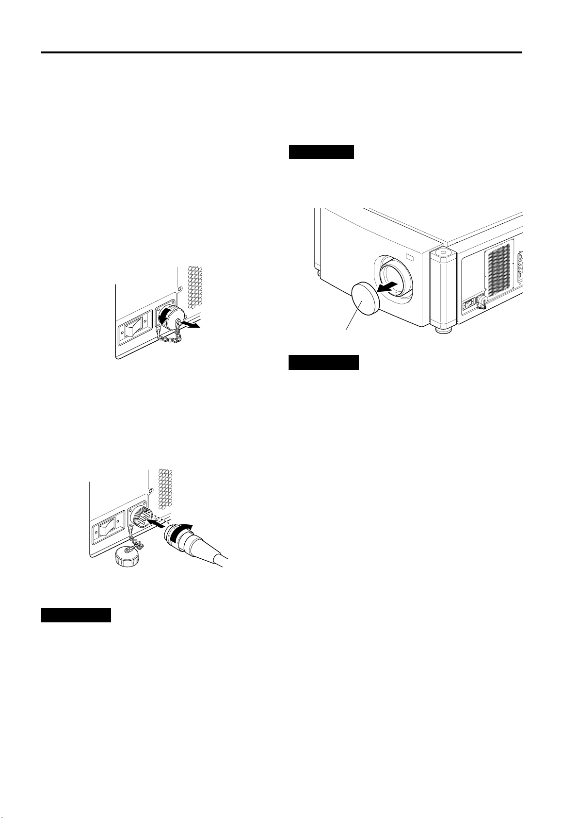
Raccordement avec différents appareils
Branchement du cordon d’alimentation (fourni)
Une fois tous les appareils raccordés, branchez le cordon d’alimentation du projecteur. À ce stade, n’allumez pas encore
l’interrupteur MAIN POWER.
■ Préparation
Raccordez une prise (adaptée à la prise de courant) au
cordon d’alimentation. Pour plus d’informations sur le
raccordement de la prise, contactez votre revendeur ou
un centre de service local.
1 Insérez le cordon d’alimentation fourni
dans la prise d’entrée (AV IN ~) du
projecteur.
1.Retirez le couvercle de la prise d’entrée
d’alimentation.
Ce couvercle est vissé. Tournez le couvercle arrière
dans le sens de la flèche pour le retirer.
2.Insérez la prise du projecteur du cordon
d’alimentation fourni dans la prise d’entrée du
projecteur.
Alignez la fente de la prise du cordon d’alimentation
du projecteur avec l’excroissance sur la prise d’entrée
d’alimentation du projecteur, et enfoncez fortement la
prise.
Après cela, tournez la bague sur la prise dans le sens
de la flèche afin de la fixer en place.
■ Pour utiliser le projecteur
• Enlevez le capuchon d’objectif.
PRECAUTION
• Veillez à ôter le capuchon de l’objectif, sinon il risquerait de
se déformer ou de fondre et provoquer un incendie ou un
mauvais fonctionnement.
Capuchon d’objectif
PRECAUTIONS
Pour éviter tout risque de choc électrique, observez ce
qui suit:
• Lorsque les appareils ne sont pas utilisés, débranchez-les
des prises murales.
• Ne raccordez pas les appareils avec d’autres cordons que
ceux fournis.
• N’utilisez pas une tension autre que celle indiquée.
• Ne coupez pas, n’endommagez pas et ne modifiez pas les
cordons d’alimentation. Il ne faut pas non plus poser d’objet
lourd, chauffer ou tirer sur les cordons d’alimentation.
Autrement, ils risquent d’être endommagés.
• Ne pas brancher ou débrancher une prise avec des mains
humides.
2 Insérez la prise du cordon d’alimentation
fourni dans une prise murale.
PRECAUTIONS
• Etant donné que le projecteur consomme beaucoup
d’électricité, veillez à brancher directement sa prise
d’alimentation dans une prise murale.
• Ce projecteur exige une prise d’alimentation 200V – 240V
une phase 3 fils.
22
Page 91

Raccordement avec différents appareils
Lors de la mise en marche des périphériques raccordés au
projecteur
Allumez les interrupteurs du projecteur et des périphériques raccordés dans l’ordre suivant.
Ignorez les périphériques non raccordés s’il y en a.
Interrupteur d’alimentation du moniteur de l’ordinateur qui fournit les signaux d’entrée au projecteur
Périphériques de l’ordinateur qui fournissent des signaux d’entrée au projecteur
(Disque dur, disque magnéto-optique, scanner, etc.)
Interrupteur d’alimentation des périphériques AV qui fournissent des signaux d’entrée au projecteur
Projecteur
Interrupteurs d’alimentation des périphériques vers lesquels le projecteur envoie des signaux de sortie
(périphériques AV et moniteur)
Interrupteur d’alimentation de l’ordinateur qui fournit des signaux d’entrée au projecteur
* Lorsque vous éteignez les interrupteurs, procédez dans l’ordre inverse.
PRECAUTIONS et REMARQUES
N’éteignez pas l’interrupteur MAIN POWER subitement lorsque le projecteur est en cours d’utilisation, ni
immédiatement après son utilisation. Cela entraînerait un mauvais fonctionnement.
• Le projecteur utilisant une lampe à forte intensité et présentant des températures élevées, des ventilateurs de
refroidissement tournent même durant la projection. Ils continuent de tourner après que vous avez appuyé sur la touche
OPERATE, jusqu’à ce que la lampe ait suffisamment refroidie. Durant le refroidissement, ne jamais éteindre l’interrupteur
d’alimentation principal. Ne l’éteignez qu’une fois que les ventilateurs de refroidissement (sauf celui de la lampe) se sont
arrêtés. (Les ventilateurs de refroidissement tournent pendant environ 10 minutes après que l’indicateur STAND BY est
passé de “clignotant” (pendant environ 20 secondes) à “allumé”.)
• Si vous appuyez sur la touche OPERATE immédiatement après l’allumage de la lampe, celle-ci ne s’éteint qu’une trentaine
de secondes plus tard. Pour rallumer la lampe, attendez au moins 20 secondes avant d’appuyer sur la touche OPERATE.
Lorsque l’indicateur TEMP s’allume, l’alimentation est coupée automatiquement.
• Lorsque la lampe est allumée, si une montée de température anormale est détectée, l’indicateur TEMP s’allume,
l’alimentation est coupée automatiquement et l’indicateur EMERGENCY du projecteur clignote (il passe en mode alerte).
ENGLISHFRANÇAISFRANÇAISITALIANOESPAÑOL
Lorsque l’indicateur EMERGENCY clignote, éteignez l’interrupteur d’alimentation principal après l’arrêt des
ventilateurs.
• Si l’anormalité suivante se produit, le projecteur passe en mode alerte (l’indicateur EMERGENCY clignote).
Lorsque le projecteur passe en mode alerte, il interrompt automatiquement la projection et les ventilateurs de
refroidissement continuent de tourner pendant environ 10 minutes (sauf le ventilateur de refroidissement de l’alimentation
de la lampe, qui continue de tourner tant que le commutateur MAIN POWER est allumé).
–Lorsque la lampe s’éteint subitement.
–Lorsque les ventilateurs s’arrêtent.
–Lorsque la température interne est anormalement élevée.
• Lorsque le projecteur passe en mode alerte :
Une fois les ventilateurs arrêtés, éteignez l’interrupteur MAIN POWER et débranchez le cordon d’alimentation. Après cela,
réinsérez le cordon d’alimentation et essayez de faire fonctionner le projecteur. S’il repasse en mode d’alerte, après l’arrêt
des ventilateurs, éteignez l’interrupteur d’alimentation, débranchez le cordon d’alimentation et consultez votre revendeur ou
centre de service agréé pour une réparation.
23
Page 92

Fonctionnement de base
Touches du projecteur
■
Indicateur STAND BY
Indicateur OPERATE
STAND BY
OPERATE
Touche OPERATE 2
Interrupteur MAIN POWER 1,
LAMP
TEMP
EMERGENCY
2
Ce qui suit décrit la procédure de base pour une utilisation
normale du projecteur.
1. Mettre sous tension
Allumez l’interrupteur MAIN POWER du
1
projecteur.
ON [ ❙ ] : L’appareil est mis sous tension et l’indicateur
RGB
AV
1
,
Appuyer sur la touche OPERATE pendant une
2
seconde ou plus.
(Ou appuyez sur la touche OPERATE de la
télécommande pendant une seconde ou plus.)
• L’indicateur OPERATE s’allume.
• Environ 30 secondes après l’activation du
commutateur MAIN POWER, vous pouvez commencer
la projection.
STAND BY s’allume.
Télécommande
OPERATE
Indicateur du Projecteur
STAND BY
Projecteur
ou
OPERATE
Télécommande
■
QUICK
ALIGN.
PRESET
LOCK UNLOCK
LENS
SHIFT ZOOM FOCUS
Avertissement relatif aux projections
■
AV HIDE
PAGE BACK
M
RGB/COMPUTER
AV
UT
DW
LENS
OPERATE
E
N
U
/
+
–
Touche OPERATE 2,
E
N
T
E
R
prolongées :
Lorsque vous effectuez une projection prolongée,
assurez-vous d’éteindre la lampe pendant au moins
deux minutes toutes les 72 heures de projection
continue.
Dans le cas contraire, vous risquez d’endommager la
lampe et de réduire sa durée de vie.
Remarque
• Après la mise sous tension, il se peut que l’écran soit
brouillé pendant quelques secondes ; ceci ne traduit pas un
mauvais fonctionnement.
1
Mise hors tension
■
Appuyer sur la touche OPERATE pendant
1
une seconde ou plus.
(Ou appuyez sur la touche OPERATE de la
télécommande pendant une seconde ou
plus.)
• L’indicateur STAND BY se met à clignoter et le
projecteur entre en mode de refroidissement.
Exemple de touche
du projecteur
Projecteur
\
OPERATE
Eteignez l’interrupteur MAIN POWER une
2
STAND BY
fois les ventilateurs de refroidissement
arrêtés.
OFF [‡‡‡‡] : L’interrupteur MAIN POWER est arrêté et
l’indicateur STAND BY s’éteint.
Projecteur
STAND BY
* Ne pas couper le commutateur MAIN POWER pendant
le mode de refroidissement (l’indicateur STAND BY
clignote). Environ 10 minutes après l’allumage de
l’indicateur STAND BY (mode d’attente), les
ventilateurs de refroidissement (sauf celui de la lampe)
s’arrêtent et l’interrupteur MAIN POWER s’éteint.
24
Page 93

Fonctionnement de base
■ Touches du projecteur
Touche AV
TEMP
LAMP
EMERGENCY
RGB
AV
Touche RGB
■ Télécommande
Commutateur LENS LOCK j UNLOCK
QUICK
LOCK UNLOCK
ALIGN.
PRESET
LENS
OPERATE
AV HIDE
PAGE BACK
M
E
N
U
/
E
RGB/COMPUTER
AV
UT
SHIFT ZOOM FOCUS
DW
LENS
+
–
N
T
E
R
Touche AV
Touche RGB
Touches ZOOM (T/W)
SETTING
QUICK
ALIGN.
2. Sélection de l’entrée vidéo à projeter
■ Appuyer sur la touche AV ou RGB pour
basculer l’entrée.
• A chaque action sur une de ces touches, l’entrée
sélectionnée change comme suit.
Lorsque vous appuyez sur VIDEO:
Y/C*
VIDEO
Lorsque vous appuyez sur COMPUTER:
RGB 1
Affichage sur écran
YPBPR
* Lorsque l’entrée est basculée, l’affichage ligne et
l’affichage source sont indiqués sur la partie supérieure
de l’écran (ils disparaissent après environ cinq
secondes). Toutefois, ils ne sont pas indiqués si AFF
SOURCE dans “Réglage et ajustement d’autres
fonctions (OPTIONS)” à la page 40 est réglé sur OFF.
(Pour le réglage de la source, voir page 43.)
YPBPR
RGB 2
CH: 1
HDTV(1080i)
PRECAUTIONS
• NE PAS faire subir de choc au projecteur lors de son
fonctionnement ; en cas de choc, la lampe s’éteint
(l’indicateur EMERGENCY s’allume).
Si le choc éteint la lampe —
Coupez l’alimentation en appuyant sur l’interrupteur
MAIN POWER, puis rétablissez l’alimentation.
Ensuite, lorsque l’indicateur STAND BY s’allume,
vous pouvez faire fonctionner le projecteur
normalement.
3. Réglage de la taille de l’écran
■ Réglez la taille de l’écran à l’aide des
touches ZOOM (T/W) de la télécommande.
Lors du réglage de la taille de l’écran avec les touches
ZOOM, réglez le commutateur LENS LOCK j UNLOCK
sur la position UNLOCK.
Pour augmenter la taille de l’écran :
Appuyez sur la touche ZOOM (W).
Pour réduire la taille de l’écran :
Appuyez sur la touche ZOOM (T).
Télécommande
+
FOCUS
–
Remarques
• Le réglage de la taille de l’écran (réglage du zoom) peut
aussi s’effectuer par l’intermédiaire du menu de réglage.
Pour plus d’informations sur l’utilisation de ce menu, voir
“Réglages de base” à la page 29.
• Lorsque vous utilisez un objectif à mise au point fixe, vous
ne pouvez pas utiliser le menu de réglage.
ENGLISHFRANÇAISFRANÇAISITALIANOESPAÑOL
25
Page 94

Fonctionnement de base
■ Touches du projecteur
EMERGENCY
AV
RGB
SETTING
■ Télécommande
Commutateur LENS LOCK j UNLOCK
Touche QUICK ALIGN.
QUICK
ALIGN.
PRESET
LOCK UNLOCK
LENS
SHIFT ZOOM FOCUS
AV HIDE
PAGE BACK
M
E
RGB/COMPUTER
AV
UT
DW
LENS
OPERATE
N
U
/
E
N
T
+
–
E
R
Touches FOCUS (+/–)
QUICK
ALIGN.
Touche QUICK ALIGN.
4. Réglage de la mise au point
■ Réglez la mise au point à l’aide des touches
FOCUS (+/–) de la télécommande.
Lors du réglage de la mise au point avec les touches
FOCUS, réglez le commutateur LENS LOCK j
UNLOCK sur la position UNLOCK.
Télécommande
+
FOCUS
–
Remarque
• Le réglage de la mise au point peut aussi s’effectuer par
l’intermédiaire du menu de réglage. Pour plus
d’informations sur l’utilisation de ce menu, voir “Réglages
de base” à la page 29.
Autres fonctions
■ Pour utiliser la fonction d’alignement rapide
La fonction d’alignement rapide permet d’ajuster (définir)
automatiquement les paramètres d’écran TRACK,
PHASE, POSITION H. et POSITION V. de l’entrée vidéo
de système informatique.
• Utilisez la touche de la télécommande ou du projecteur.
Lorsque vous utilisez la télécommande :
Appuyez sur la touche QUICK ALIGN..
Lorsque vous utilisez le projecteur :
Effacez l’affichage du menu, puis appuyez simultanément
sur les touches QUICK ALIGN. “++++” et “----” du projecteur.
* Pendant l’ajustement automatique, “QUICK-
ALIGNMENT” (Alignement rapide) apparaît à l’écran
puis disparaît automatiquement une fois l’alignement
terminé.
Télécommande Projecteur
QUICK
ALIGN.
QUICK
ALIGN.
Affichage sur écran
26
QUICK-ALIGNMENT
Remarque
• Cette fonction n’est valable que pour les entrées de
système informatique.
PRECAUTION
• Lors de l’ajustement automatique avec la fonction
d’alignement rapide :
Utilisez un écran avec une image lumineuse et fixe. Cette
fonction peut ne pas marcher correctement avec une
image sombre ou en mouvement.
Si la condition réglée à l’aide de la fonction d’alignement
rapide n’est pas très bonne, réglez manuellement TRACK,
PHASE, POSITION H. et POSITION V. (voir pages 29, 35
et 36).
Page 95

Fonctionnement de base
■ Touche du projecteur
TEMP
EMERGENCY
LAMP
AV
■ Télécommande
QUICK
ALIGN.
PRESET
LOCK UNLOCK
LENS
AV
UT
SHIFT ZOOM FOCUS
DW
AV HIDE
LENS
OPERATE
PAGE BACK
M
E
N
U
/
E
N
T
E
R
RGB/COMPUTER
+
–
SETTING
RGB
Touche SETTING
Touche PRESET
Touche MENU/ENTER
QUICK
ALIGN.
■ Pour afficher le menu REGLAGE
Le menu de réglage permet d’effectuer des réglages de
base (TRACK, PHASE, POSITION H., POSITION V.,
FOCUS et ZOOM) sur l’image vidéo projetée après
installation (raccordement) ou après basculement des
entrées. Pour plus d’informations sur l’utilisation de ce
menu, voir “Réglages de base” à la page 29.
• Appuyez sur la touche SETTING du projecteur.
Le menu de réglage est affiché à l’écran.
Télécommande
SETTING
■ Pour afficher le menu MAIN
Le menu principal permet d’ajuster ou de définir l’image
vidéo projetée et la condition du projecteur, etc.
(HORLOGE PIXCEL, POSITION, IMAGE, OPTIONS,
SOURCE, DECODUER et LANGUAGE). Pour plus
d’informations sur l’utilisation de ce menu, voir pages 32 à
57.
• Appuyez sur la touche MENU/ENTER de la
télécommande.
Le menu principal apparaît à l’écran.
Télécommande
M
E
N
U
/
E
N
T
E
R
Remarque
• Pour modifier la langue du menu affiché
A la sortie d’usine, c’est l’anglais qui est la langue définie.
La langue d’affichage peut être choisie parmi les six
langues suivantes :
N
N
(japonais), ENGLISH,
NN
DEUTSCH (allemand), ESPAÑOL (espagnol), ITALIANO
(italien) et FRANÇAIS (français). Cependant, certains
termes tels que “QUICK-ALIGNMENT” (Alignement rapide)
ne sont affichés qu’en anglais. Les pronoms tels
qu’affichage de ligne et affichage de source sont traités de
la même façon.
■ Pour effacer le menu MAIN
Utilisez la touche PAGE BACK pour effacer le menu
principal. Pour plus d’informations sur l’utilisation de la
touchePAGE BACK, voir pages 32 à 57.
• Lorsque le menu principal est affiché, appuyez sur
PAGE BACK sur la télécommande.
Le menu principal disparaît.
Télécommande
PAGE BACK
ENGLISHFRANÇAISFRANÇAISITALIANOESPAÑOL
27
Page 96

Fonctionnement de base
■ Télécommande ■ Pour afficher “CHANNEL” à l’écran
QUICK
ALIGN.
PRESET
LOCK UNLOCK
LENS
AV
UT
SHIFT ZOOM FOCUS
DW
AV HIDE
LENS
OPERATE
PAGE BACK
M
E
N
U
/
E
N
T
E
R
RGB/COMPUTER
+
–
Touche AV HIDE
Touche PAGE BACK
Touche PRESET
Lorsqu’aucun menu n’est affiché, une pression sur la
touche PAGE BACK provoque l’affichage du canal utilisé
actuellement.
Vous pouvez aussi basculer d’un canal à un autre. Pour
plus de détails, référez-vous à “Pour faire basculer les
canaux à l’aide d’un “DIRECT CHANNEL”” à la page 51.
• Lorsqu’aucun menu n’est affiché, appuyez sur
PAGE BACK sur la télécommande.
Le canal apparaît à l’écran.
Télécommande
PAGE BACK
■ Pour effacer temporairement l’image vidéo
Appuyez sur la touche AV HIDE ; l’image vidéo disparaît
alors temporairement de l’écran. Une nouvelle pression
sur cette touche restaure l’image vidéo.
• Appuyez sur AV HIDE sur la télécommande.
L’image vidéo disparaît temporairement de l’écran.
Télécommande
AV HIDE
■ Pour utiliser la touche PRESET de la
télécommande
La touche PRESET est utilisée pour les réglages
effectués dans le menu principal ou le menu de réglage.
• Lorsque vous souhaitez restaurer uniquement les
paramètres sélectionnés sur leurs valeurs d’usine,
appuyez sur la touche PRESET de la télécommande.
Seul l’élément sélectionné est restauré sur sa valeur
d’usine.
Télécommande
PRESET
Remarques
• Cette touche ne fonctionne qu’avec les valeurs
numériques. Elle ne permet pas de basculer entre ON et
OFF.
• Pour les éléments comme HORLOGE PIXCEL (TRACK et
PHASE), POSITION (POSITION H. et POSITION V.), les
deux paramètres sont réinitialisés en même temps.
28
Page 97

Utilisation du menu de réglage
Réglages de base
■
Touches du projecteur
Touche SETTING
EMERGENCY
■
Menu de réglage
REGLAGE
TRACK
PHASE
POSITION H.
POSITION V.
FOCUS –
ZOOM W
SHIFT LENS
AV
RGB
SETTING
QUICK
ALIGN.
Touche QUICK ALIGN.
10
0
0
0
+
T
Dans cette section, nous allons réaliser des réglages de
base de l’image qui doivent être exécutés après l’installation
(raccordement).
Remarques
• Le menu de réglage est affiché lorsque vous appuyez sur
la touche SETTING du projecteur. Une fois le menu affiché,
vous pouvez effectuer des réglages (ajustements).
• Si la position ou les raccordements du projecteur ont
changé, vous devez réeffectuer les réglages et ajustements.
• Une fois les ajustements effectués, si des réglages
supplémentaires de l’image sont nécessaires, en fonction des
équipements raccordés, utilisez le menu principal (pages 32 à
57) pour effectuer des réglages et ajustements détaillés.
• Pour les entrées d’ordinateur, l’utilisation de la fonction
d’alignement rapide permet d’effectuer un ajustement
automatique de TRACK, PHASE, POSITION H. et
POSITION V. (Voir pages 29, 35 et 36).
Appuyez sur la touche SETTING du
1
projecteur.
• Le menu de réglage est affiché à l’écran.
Appuyez sur la touche SETTING pour
2
sélectionner l’élément souhaité.
• L’élément sélectionné est affiché en magenta. À
chaque pression sur cette touche, l’élément
sélectionné change comme suit :
TRACK
PHASE
POSITION H. POSITION V.
Ajustement • niveau de réglage
Description des éléments de réglage
TRACK :
PHASE :
POSITION H. :
POSITION V. :
FOCUS :
ZOOM :
SHIFT LENS :
Si de larges bandes verticales apparaissent à
l’écran, ajustez la taille vidéo latérale et la zone
d’affichage de façon à les faire disparaître.
(–255
Si les caractères à l’écran papillotent ou
s’assombrissent, effectuez une correction pour les
éclaircir. (–127
Si l’écran est déplacé vers la gauche ou vers la
droite, ajustez sa position horizontale.
(–255
Si l’écran est déplacé vers le haut ou vers le bas,
ajustez sa position verticale. (–120
Ajuste la mise au point de l’image vidéo.
– : Effectue la mise au point sur des points plus
+ : Effectue la mise au point sur des points plus
Ajuste la taille de l’écran (angle de vue).
T : Rétrécit.
W : S’agrandit
Ajuste la position de l’écran projeté.
∞ : La déplace vers le bas.
5 : La déplace vers le haut.
0 Ô +255)
Ô
0 Ô +255)
Ô
proches.
éloignés.
0 Ô +127)
Ô
0 Ô +120)
Ô
Effacement
du menu
SHIFT LENS
ZOOM
FOCUS
Mémo
Pour sélectionner des éléments à l’aide de la
télécommande :
Vous pouvez sélectionner des éléments à l’aide des touches
curseur 5 (arrière) ou ∞ (avant) de la télécommande. Dans
ce cas, l’effacement du menu dans l’ordre ci-dessus n’est
pas disponible. La sélection change directement de SHIFT
LENS à TRACK.
Ajustez et définissez l’élément
3
sélectionné à l’aide des touches QUICK
ALIGN. ++++ ou ----.
• Pour ajuster et définir plusieurs éléments, répétez les
étapes 2 et 3.
• Pour restaurer la valeur d’usine de l’élément
sélectionné (TRACK, PHASE, POSITION H. ou
POSITION V.), appuyez sur la touche PRESET de la
télécommande. Cette touche ne fonctionne pas pour la
mise au point ni le zoom.
Mémo
Pour ajuster et définir des éléments à l’aide de la
télécommande :
Les éléments peuvent être ajustés ou définis en appuyant
sur la touche MENU/ENTER vers la marque 2 ou 3 sur la
télécommande.
Effacez le menu en appuyant sur la
4
touche SETTING de manière répétée.
ENGLISHFRANÇAISFRANÇAISITALIANOESPAÑOL
Mémo
Pour effacer le menu de réglage à l’aide de la
télécommande :
Vous pouvez aussi effacer le menu de réglage en appuyant
sur la touche PAGE BACK sur la télécommande.
29
Page 98

Utilisation du menu principal
Configuration du menu principal (Entrée AV)
Pour les entrées d’ordinateur, voir
page suivante.
Vous pouvez ajuster la qualité vidéo (IMAGE), etc. à l’aide des menus.
Les menus sont configurés comme suit : Menu principal (Entrées AV : Avec le signal d’entrée EXT. IN)
Menu principal (Entrées AV : Avec le signal d’entrée EXT. IN)
HORLOGE PIXCEL
POSITION
IMAGE LUMINOSITE : Ajustement de la luminosité de l’image vidéo projetée.
OPTIONS MENU ARRET AUTO : Permet de désactiver l’affichage du menu automatiquement (OUI) ou non (NON).
SOURCE : Normalement réglé sur AUTO. Si l’utilisation sur AUTO entraîne une instabilité (couleurs qui n’apparaissent
CHANNEL : Définit une ligne et des sources multiples pour chaque canal.
USER SOURCE SET UP :
DISPLAY SIZE : Ne fonctionne pas pour les signaux d’entrée AV [EXT. IN (VIDEO, Y/C, YPBPR)]. (Les éléments à ajuster
DECODUER : Normalement, réglez sur AUTO. Le système de couleur d’un signal d’entrée est automatiquement identifié et
LANGUAGE : Le texte à l’écran peut être affiché en une langue autre que l’anglais. Les langues pouvant être affichées
TRACK : Normalement, aucun réglage n’est requis. Ajustement de la taille latérale et de la
PHASE : Normalement, aucun réglage n’est requis. Ajustement du papillotement ou d’une
POSITION V. : Ajustement de la position verticale de l’image vidéo projetée.
POSITION H. : Ajustement de la position horizontale de l’image vidéo projetée.
CONTRASTE : Ajustement du contraste de l’image vidéo projetée.
DETAIL : Ajustement de la netteté de l’image vidéo projetée.
COULEUR : Ajustement de la densité de couleur de l’image vidéo projetée.
TEINTE : Ajustement de la teinte de l’image vidéo projetée. (Affiché uniquement pour le signal
RAZ : Tous les éléments ajustés sont réinitialisés.
AFF SOURCE : Permet de rendre effectif l’affichage de ligne (ON) ou non (OFF) pendant environ 5
INVERS D-G : Inverse l’image vidéo de droite à gauche.
INVERS H-B : Inverse l’image vidéo de haut en bas.
CLAMP : Règle la position de l’impulsion de verrouillage sur le palier arrière (BP) ou sur la
REDIMENSION : Ne fonctionne pas avec l’entrée (vidéo) AV. (REDIMENSION est affiché en gris.)
COULEUR FOND : Spécifie la couleur de l’arrière-plan lorsqu’il n’y a aucun signal vidéo. Les différents
TEMP.COULEUR : Ajuste la température de couleur de l’image projetée. Effectuez cet ajustement
CHG FORMAT : Sélectionne le rapport vertical/horizontal de l’image projetée. Le rapport réglé en
VEILLE : Définit la minuterie. Une fois cette durée dépassée après suppression du signal
TEMPS LAMPE : Indique les heures d’utilisation de la lampe source de lumière.
pas, écran perturbé ou affichage intermittent, par exemple), définissez la source dédiée (mode forcé) en
fonction du signal d’entrée.
USER vous permet de définir une source ajustée uniquement par l’utilisateur.
Définit une zone pour la source entrée et enregistre le nom d’utilisateur.
sont affichés en gris.)
indiqué entre ( ). Lorsque l’utilisation sur AUTO est instable (par exemple aucune couleur affichée),
définissez le système de couleur dédié en fonction du signal d’entrée. Vous pouvez sélectionner AUTO,
NTSC(480i), NTSC4.43, PAL et SECAM.
sont les suivantes :
ITALIANO (italien) et FRANÇAIS (français). Cependant, certains termes tels que “QUICK-ALIGNMENT”
(Alignement rapide) ne sont affichés qu’en anglais.
zone d’affichage de l’image vidéo.
image vidéo sombre.
NTSC)
secondes après le basculement d’entrée.
pointe de collecteur (ST). Normalement, l’impulsion de verrouillage est utilisée sur
BP. Si, avec certains PC ou stations de travail, l’écran devient instable (trop sombre
ou trop clair), essayez de basculer sur ST.
choix possibles pour la couleur de l’arrière-plan sont BLEU, CYAN, NOIR, VERT,
MAGENTA, ROUGE et JAUNE.
lorsque l’image est trop rouge ou trop bleue.
La température de couleur peut être réglée sur BASSE, NORMAL ou HAUTE.
usine est 4 : 3. Lors de la projection d’image vidéo de haute-définition, un rapport de
16 : 9 peut être sélectionné.
d’entrée, le projecteur passe en mode d’attente. Vous pouvez sélectionner une
durée de 10 minutes, 20 minutes, 30 minutes, 60 minutes ou 0 minute. (Si vous
sélectionnez 0 minute, la minuterie est désactivée.)
(japonais), ENGLISH(anglais), DEUTSCH (allemand), ESPAÑOL (espagnol),
N
N
NN
30
Page 99

Utilisation du menu principal
Configuration du menu principal (entrée d’ordinateur)
Menu principal (Entrées d’ordinateur : Avec le signal d’entrée COMPUTER IN -1 ou -2)
HORLOGE PIXCEL TRACK : Ajustement de la taille latérale et de la zone d’affichage de l’image vidéo.
PHASE : Ajustement du papillotement ou d’une image vidéo sombre.
POSITION POSITION V. : Ajustement de la position verticale de l’image vidéo projetée.
POSITION H. : Ajustement de la position horizontale de l’image vidéo projetée.
IMAGE LUMINOSITE : Ajustement de la luminosité de l’image vidéo projetée.
CONTRASTE : Ajustement du contraste de l’image vidéo projetée.
GAIN-R : Ajustement du gain en signal rouge de l’image vidéo projetée.
GAIN-V : Ajustement du gain en signal vert de l’image vidéo projetée.
GAIN-B : Ajustement du gain en signal bleu de l’image vidéo projetée.
MODE TEXTE : Ajustement de la facilité de lecture du texte durant REDIMENSION.
RAZ : Tous les éléments ajustés sont réinitialisés.
OPTIONS MENU ARRET AUTO : Permet de désactiver l’affichage du menu automatiquement (OUI) ou non (NON).
AFF SOURCE : Permet de rendre effectif l’affichage de ligne (ON) ou non (OFF) pendant environ 5
INVERS D-G : Inverse l’image de droite à gauche.
INVERS H-B : Inverse l’image de haut en bas.
CLAMP : Règle la position de l’impulsion de verrouillage sur le palier arrière (BP) ou sur la
REDIMENSION : Lorsque le nombre de pixels (résolution) recherché par l’entrée d’image vidéo est
COULEUR FOND : Spécifie la couleur de l’arrière-plan lorsqu’il n’y a aucun signal image. Les différents
TEMP.COULEUR : Ajuste la température de couleur de l’image vidéo projetée. Effectuez cet
CHG FORMAT : Sélectionne le rapport vertical/horizontal de l’image vidéo projetée. Le rapport réglé
VEILLE : Définit la minuterie. Une fois cette durée dépassée après suppression du signal
TEMPS LAMPE : Indique les heures d’utilisation de la lampe source de lumière.
SOURCE : Normalement réglé sur AUTO. Si l’utilisation sur AUTO entraîne une instabilité (couleurs qui n’apparaissent
CHANNEL : Définit une ligne et des sources multiples pour chaque canal.
USER SOURCE SET UP : Définit une zone pour la source entrée et enregistre le nom d’utilisateur.
DISPLAY SIZE : Ajuste les paramètres H PIXEL, V PIXEL, H CENTER and V CENTER de l’image vidéo.
DECODUER : Ne fonctionne pas avec les entrées d’ordinateur. (Le système de couleur est indiqué en gris.)
LANGUAGE : Le texte à l’écran peut être affiché en une langue autre que l’anglais. Les langues pouvant être affichées
pas, écran perturbé ou affichage intermittent, par exemple), définissez la source dédiée (mode forcé) en
fonction du signal d’entrée.
USER vous permet de définir une source ajustée uniquement par l’utilisateur.
sont les suivantes :
ITALIANO (italien) et FRANÇAIS (français). Cependant, certains termes tels que “QUICK-ALIGNMENT”
(Alignement rapide) ne sont affichés qu’en anglais.
NORMAL : Normal
TEXTE 1 : Affiche le contour des petites lettres.
TEXTE 2 : Rend le contour des grosses lettres plus net.
secondes après le basculement d’entrée.
pointe de collecteur (ST). Normalement, l’impulsion de verrouillage est utilisée sur
BP. Si, avec certains PC ou stations de travail, l’écran devient instable (trop sombre
ou trop clair), essayez de basculer sur ST.
inférieur à la résolution du périphérique D-ILA, l’image vidéo est agrandie presque
jusqu’en plein écran de périphérique D-ILA, puis projetée. (Indication de
redimensionnement)
choix possibles pour la couleur de l’arrière-plan sont BLEU, CYAN, NOIR, VERT,
MAGENTA, ROUGE et JAUNE.
ajustement lorsque l’image vidéo est trop rouge ou trop bleue.
La température de couleur peut être réglée sur BASSE, NORMAL ou HAUTE.
en usine est 4 : 3. Lors de la projection d’image de haute-définition, un rapport de
16 : 9 peut être sélectionné.
d’entrée, le projecteur passe en mode d’attente. Vous pouvez sélectionner une
durée de 10 minutes, 20 minutes, 30 minutes, 60 minutes ou 0 minute. (Si vous
sélectionnez 0 minute, la minuterie est désactivée.)
(japonais), ENGLISH(anglais), DEUTSCH (allemand), ESPAÑOL (espagnol),
N
N
NN
ENGLISHFRANÇAISFRANÇAISITALIANOESPAÑOL
31
Page 100

Utilisation du menu principal
Utilisation du menu principal (Utilisation de base du menu
principal)
■ Télécommande
QUICK
LOCK UNLOCK
LENS
ALIGN.
PRESET
AV HIDE
OPERATE
PAGE BACK
M
E
N
U
/
E
N
Touche PAGE BACK
T
E
R
Touche MENU/ENTER
RGB/COMPUTER
AV
UT
SHIFT ZOOM FOCUS
DW
LENS
+
–
■ Menu principal
Eléments de sous-menu
Ligne d’entrée
YPBPR
HORLOGE PIXCEL
POSITION
IMAGE
OPTIONS
SOURCE
CHANNEL
USER SOURCE SET UP
DISPLAY SIZE
DECODUER
LANGUAGE
Décodeur (système de couleur) Langue
Source
NTSC(480i)
FRANÇ AIS
Canal
CH: 1
HDTV(1080i)
En ce qui concerne les menus du projecteur, le menu de
réglage et le menu principal sont disponibles.
Nous expliquons ici le fonctionnement du menu principal.
Pour des informations sur le menu de réglage, consultez
“Réglages de base” à la page 29.
Appuyez sur la touche MENU/ENTER.
1
• Le menu principal est affiché à l’écran.
Appuyez sur MENU/ENTER vers la
2
marque 5 ou ∞ pour sélectionner un
élément.
• L’élément sélectionné (texte affiché) est affiché en
magenta à l’écran.
Définissez (ajustez) l’élément.
3
Lorsque vous avez sélectionné DECODUER ou
la langue,
• Appuyez sur MENU/ENTER vers la marque 2 ou 3
pour définir le paramètre.
* Pour quitter le menu principal, appuyez sur la touche
PAG E B AC K .
Lorsque vous avez sélectionné un élément
dans le sous-menu,
• Appuyez sur MENU/ENTER pour afficher le sous-menu.
Ensuite, définissez (ajustez) l’élément en appuyant sur
MENU/ENTER vers la marque 2/3 ou 5/∞.
* Pour revenir au menu principal, appuyez de nouveau
sur PAGE BACK. Pour quitter le menu principal,
appuyez de nouveau sur PAGE BACK. (Pour quitter le
menu principal à partir du sous-menu, appuyez deux
fois sur la touche PAGE BACK.)
■ A propos de l’affichage du menu principal :
Affichage
Ligne :
Affichage de
la source :
Affichage du
canal :
Affichage de
l’élément de
sous-menu :
Affichage du
décodeur
(système de
couleur) :
Affichage de
la langue :
La désignation du mode d’entrée sélectionné est
affichée. Pour la désignation du mode d’entrée, “Y/
C”, “VIDEO”, “YPBPR”, “RGB 1” et “RGB 2” sont
disponibles.
Le type de signal entré est affiché ici. Avec ce
projecteur, des désignations uniques sont données
à des fréquences horizontales et verticales
spécifiques. Ceci permet d’indiquer la source
sélectionnée sous SOURCE (élément de sousmenu). Les choix disponibles pour la source sont le
mode AUTO, les modes dédiés (forcés) et le mode
USER. Lorsque AUTO est sélectionné, les
fréquences horizontales et verticales d’un signal
entré sont détectées et la désignation
correspondante est affichée entre( ).
Par conséquent, faites attention car l’affichage de
la source ne correspond pas toujours à l’indication
ou au type du signal d’entrée.
Pour plus d’informations sur les désignations
uniques des fréquences horizontales et verticales
uniques, voir page 18.
Le canal sélectionné par l’utilisateur est affiché. La
ligne et la source sélectionnées par l’utilisateur ont
été enregistrées dans le canal. Une fois
enregistrées, la ligne et les sources du projecteur
changeront en celles enregistrées par l’utilisateur
uniquement lors du basculement d’un canal à
l’autre. Les réglages doivent être effectués dans le
“menu de sélection/configuration de canal”. Pour
plus de détails, voir page 46.
Voir pages 35 à 57.
Voir page 33.
Voir page 34.
32
 Loading...