

Page 1

TM
D-ILA
PROJECTOR
DLA-G3010
DLA-G3010series
DLA-G3010DLA-G3010
DLA-M2000
DLA-M2000series
DLA-M2000DLA-M2000
series
seriesseries
series
seriesseries
RS-232C CONTROL SPECIFICATIONS
Victor Company of Japan, Limited
* D-ILA is a trademark of Victor Company of Japan, Limited.
Document Number CTGKE-0013
Page 2

1. Outline ..........................................................................................................................2
2. Communication Format.................................................................................................. 2
3. Data Format ..................................................................................................................2
4. Header ..........................................................................................................................4
5. ID.................................................................................................................................. 4
6. CR ................................................................................................................................5
7. Parameters....................................................................................................................5
8. Tally (Response) Data ................................................................................................... 9
9. Internal Errors ............................................................................................................. 10
10 Projector Operation Modes .......................................................................................... 12
11. Source ........................................................................................................................ 13
12. Commands.................................................................................................................. 14
13. Appendix .....................................................................................................................55
CONTENTS
1
Page 3

1.
1.
1.1.
This document describes the communication and data formats used to control the projector via
its RS-232C port.
2.
2.
2.2.
Transfer Rate : 9600, 19200(default) bps
Data Length : 8 bits
Parity Bit : None
Start Bit : 1 bit
3.
3.
3.3.
3.1
Header ID SP Command SP Parameter SP Parameter SP ・・ CR
Header : Indicates the beginning of data and data type
‘!’(21H) : Command for the Projector
‘?’(3FH) : Query to the Projector (Request for data)
ID : Identification number of Projector
SP : Indicates the separation between ID and command, command and parameter,
CR : Indicates the end of data(0DH)
3.2
3.2.1 Tally (Response) Data when Terminated Normally
Header ID SP Normal Termination Status SP Parameter SP Parameter ・・ CR
Header : Indicates the beginning of tally (response) data
‘@’(40H)
ID : Identification number of the Projector
SP : Indicates the separation between ID and status, status and parameter,
Normal Termination : ‘0’(30H)
Status
CR : Indicates the end of data(0DH)
* Parameter is sent when tally (response) data is issued in response to a query (request for data.) There is
OUTLINE
COMMUNICATION FORMAT
Flow Control : None
DATA FORMAT
Command Data Format (External Control to Projector)
parameter and parameter(20H)
Tally (Response) Data Format (Projector to External Control)
parameter and parameter(20H)
2
Page 4

no parameter for tally (response) data in response to a command.
3.2.2 Tally Data when Error Occurs
Header ID SP Error Status CR
Header : Indicates the beginning of the tally (response) data
‘@’(40H)
ID : Identification number of Projector
SP : Indicates the separation between ID and Status(20H)
Error : ‘A00’ (41H 30H 30H)
Status ‘A01’ (41H 30H 31H)
‘A02’ (41H 30H 32H)
‘A03’ (41H 30H 33H)
‘A04’ (41H 30H 34H)
‘A05’ (41H 30H 35H)
‘A0A’ (41H 30H 41H)
‘A0B’ (41H 30H 42H)
CR : Indicates the end of the data(0DH)
*For details on error status, refer to 8. Tally (Response) Data.
Internal Error Data Format (Projector to External Control)
3.3
Header ID SP Internal Error Status SP Parameter SP Parameter SP ・・ CR
Header : Indicates the beginning of the internal error data
‘&’(26H)
ID : Identification of Projector
SP : Indicates the separation between ID and status, status and parameter,
parameter and parameter(20H)
Internal Error : ‘E01’ (45H 30H 31H)
Status ‘E02’ (45H 30H 32H)
‘E03’ (45H 30H 33H)
‘E04’ (45H 30H 34H)
‘E06’ (45H 30H 36H)
‘E07’ (45H 30H 37H)
‘E08’ (45H 30H 38H)
‘E09’ (45H 30H 39H)
‘E0B’ (45H 30H 42H)
‘E0C’ (45H 30H 43H)
‘E11’ (45H 31H 31H)
‘E12’ (45H 31H 32H)
‘E20’ (45H 32H 30H)
CR : Indicates the end of the data(0DH)
* For details on internal error status, refer to 9. Internal Errors.
3
Page 5
4.
4.
4.4.
Indicates the beginning and type of communication data.
4.1
4.2
HEADER
External Control to Projector
Character HEX Definition
‘!’ 21 Command to the Projector
‘?’ 3F Query (request for information) to the Projector
Projector to External Control
Character HEX Definition
‘@’ 40 Tally (Response) data
5. ID
Numeric characters are used to identify an individual Projector when two or more Projector units are
connected to a single control machine.
Setting separate identification numbers for each Projector allows independent control of each
Projector unit.
# Assignable ID numbers
‘0’(30H) ‘8’ (38H)
‘1’(31H) ‘9’ (39H)
‘2’(32H) ‘A’ (41H)
‘3’(33H) ‘B’ (42H)
‘4’(34H) ‘C’ (43H)
‘5’(35H) ‘D’ (44H)
‘6’(36H) ‘E’ (45H)
‘7’(37H) ‘F’ (46H)
* Factory set ID is ‘1’ (31H).
ID number ‘0’ (30H) should be used when assigning all connected Projector units for batch operations.
This means that when assigning independent ID numbers to multiple units, 15 of the 16 assignable
numbers (from ‘1’ through ‘F’) can actually be used for registration.
Please note that tally (response) data is not returned from the projector when the global ID assignment
function (0) is used.
‘&’ 26 Internal error data
4
Page 6

6. CR
Indicates the end of each set of data. (0DH)
7. PARAMETERS
There are three types of parameters:
1.Indicates the numeric value.
2.Indicates the ON/OFF status.
3.Special parameter.
7.1 Numeric Value Parameter
Signed 2-byte hexadecimal code represented by 4 (byte) characters.
Assignable range is between ‘8000’ and ‘7FFF’.
Ex-1) The parameter indicating ‘20’ (decimal):
Since ‘20’ (decimal) is represented as ‘0014’ in signed 2-byte hexadecimal,
its parameter is:
‘0014’(30H 30H 31H 34H)
Ex-2) The parameter to indicate ‘-2’ (decimal):
Since ‘-2’ (decimal) is represented as ‘FFFE’ in signed 2-byte hexadecimal,
its parameter is:
‘FFFE’(46H 46H 46H 45H)
ON/OFF Status Parameter
7.2
Indicates the ON/OFF status of items such as POWER or HIDE.
Character HEX Definition
‘0’ 30 OFF
‘1’ 31 ON
5
Page 7
Special Parameters
7.3
Parameters other than those described in 7.1 to 7.2.
7.3.1 Menu Display Auto OFF Parameter
Character HEX Definition
‘0’ 30 NO
‘1’ 31 YES
7.3.2 Transfer Rate Parameter
Character HEX Definition
‘0’ 30 9600bps
‘1’ 31 19200bps
7.3.3 Decoder Parameter
Character HEX Definition
‘0’ 30 NTSC
‘1’ 31 NTSC4.43
‘2’ 32 PAL
‘3’ 33 SECAM
‘4’ 34 AUTO
7.3.4 Color Temperature Parameter
Character HEX Definition
‘0’ 30 LOW
‘1’ 31 MIDDLE
‘2’ 32 HIGH
7.3.5 Input Select Parameter
Character HEX Definition
‘0’ 30
‘1’ 31 VIDEO
‘3’ 33 D-SUB
‘4’ 34 BNC
Y/C
6
Page 8
7.3.6 Projector Operation Mode Parameter
Character HEX Definition
7.3.7 Text Mode Parameter
7.3.8 Aspect Parameter
‘0000’ 30H 30H 30H 30H S t a n d by M o d e
‘0001’ 30H 30H 30H 31H P o w er O N M od e
‘0002’ 30H 30H 30H 32H C oo l - D o wn M o d e
‘0004’ 30H 30H 30H 34H Em er ge n cy M o d e
Character HEX Definition
‘0’ 30 Text 1
‘1’ 31 Text 2
‘2’ 32 Text 3
‘3’ 33 Text 4
‘4’ 34 Text 5
Character HEX Definition
7.3.9 Resize Parameter
‘0’ 30
‘1’ 31
Character HEX Definition
‘0’ 30
‘1’ 31 Full
‘2’ 32 Aspect
4:3
16:9
1:1
7
Page 9
7.3.10 ID Parameter
Character HEX Definition
‘0’ 30 ID 0(global command for all projectors)
‘1’ 31 ID 1
‘2’ 32 ID 2
‘3’ 33 ID 3
‘4’ 34 ID 4
‘5’ 35 ID 5
‘6’ 36 ID 6
‘7’ 37 ID 7
‘8’ 38 ID 8
‘9’ 39 ID 9
‘A’ 41 ID 10
‘B’ 42 ID 11
7.3.11 Switcher Number Parameter
‘C’ 43 ID 12
‘D’ 44 ID 13
‘E’ 45 ID 14
‘F’ 46 ID 15
Character HEX Definition
‘ 00 01 ’ 30H 30H 30H 31H Switcher No.1
‘ 00 02 ’ 30H 30H 30H 32H
‘ 00 03 ’ 30H 30H 30H 33H
‘ 00 04 ’ 30H 30H 30H 34H
‘ 00 05 ’ 30H 30H 30H 35H
‘ 00 06 ’ 30H 30H 30H 36H
Switcher No.2
Switcher No.3
Switcher No.4
Switcher No.5
Switcher No.6
‘ 00 07 ’ 30H 30H 30H 37H
‘ 00 08 ’ 30H 30H 30H 38H
‘ 00 09 ’ 30H 30H 30H 39H
‘000A’ 30H 30H 30H 41H
8
Switcher No.7
Switcher No.8
Switcher No.9
Switcher No.10
Page 10
8. TALLY(RESPONSE)DATA
The Projector will only accept and process data when the ID number included with
the ID-number registered
matches the Projector’s ID, it will return a response to the query from the external control unit. This
response data is called "Tally (Response) Data". (However, when ID = ‘0’, tally (response) data is not
replied.)
The Tally (Response) Data is normally returned within 3 seconds after the data is received.
There are some exceptions, however (e.g. POWER command)
After transmitting data, the external control unit cannot transmit subsequent data until the Tally
(Response) Data is received. However, if Tally (Response) Data is not returned within 3 seconds after
transmitting the data (there are some exceptions such as the POWER command), data transmission can
be retried.
8.1 Tally (Response) Data Status
8.1.1 Normal Termination Status
Character HEX Definition
to the Projector itself. (Except when ID = ‘0’) If the received ID-number
the data coincides with
‘0’ 30 Command received and processing terminated
8.1.2 Status when Error Occurs (Error Status)
Character HEX Definition
‘A00’
‘A01’
‘A02’
‘A03’
‘A04’
‘A05’
‘A0A’
‘A0B’
8.2 Tally (Response) Data Parameter
The Tally (Response) Data Parameter is returned when the Tally (Response) Data is issued in
response to a query (request for data). No parameter is returned when Tally (Response) Data
issued in response to a command or when an error occurs.
41H 30H 30H
41H 30H 31H
41H 30H 32H
41H 30H 33H
41H 30H 34H
41H 30H 35H
41H 30H 41H
41H 30H 42H
Command not supported
Invalid parameter
Parameter value exceeds operation range
Unclassified error
Unacceptable command in current mode
or
Unacceptable command with current setting
Command cannot be accepted if no signal.
Time-out occurred with the communication with sub
microcomputer
Error occurred with the communication with sub
microcomputer
9
Page 11
9. INTERNAL ERRORS
Error data is returned to the external control unit when an error has occurred.
9.1 Internal Error Data Status (Internal Error Status)
Character HEX Definition
‘E01’
‘E02’
‘E03’
‘E04’
‘E06’
‘E07’
‘E08’ 45H 30H 38H I nt ern a l te m pe r atu re i s too hig h .
‘E09’ 45H 30H 39H Temperature around air intake is going up abnormally.
‘E0B’ 45H 30H 42H Error occurred with the initialization of decoder.
‘E0C’ 45H 30H 43H Initialization of Video Sources (Areas) data was failed.
‘E11’ 45H 31H 31H Sub microcomputer is not boost up correctly.
45H 30H 31H
45H 30H 32H
45H 30H 33H
45H 30H 34H
45H 30H 36H
45H 30H 37H
Lamp did not light
Lamp life exceeds guaranteed time
IIC ACK error occurs
Filter cover on the bottom of the unit is displaced
Lamp suddenly goes out (Lamp Shut Down) while
projecting
(in Power ON mode)
Fan is locked
‘E12’ 45H 31H 32H Initialization of DDIC/DDCTRL was failed.
‘E20’ 45H 32H 30H Sleep time function works and lamp was lit off.
9.2 Internal Error Data Parameters
There are two parameters for Internal Error Data.
Header ID SP Internal Error Status SP Parameter 1 SP Parameter 2 CR
Each parameter shows the slave address (Parameter 1) and Sub-Address (Parameter 2) when
an IIC ACK error (Error status: ‘E03’) occurs.
The parameter type is "numeric value".
* Two parameters are also returned when an internal errors other than IIC ACK errors occur.
In this case, however, the parameter’s numeric value has no meaning.
Ex) Internal error data when IIC ACK error occurs with Slave address ‘A0H’ and Sub-address of
‘1F20H’:
ID SP ‘E03’ SP ‘00A0’ SP ‘1F20’ CR
‘&’
10
Page 12

9.3 Internal Error Data Reply Timing
When returning data, the Projector checks for internal error data. If such data exists, the internal
error data is returned before the tally (response) data is transmitted.
occurs, the Projector retains the internal error data, returning it in order of precedence a request
for tally (response) data is received. Once transmitted, internal error data is deleted from the
Projector.
That is, if an internal error
11
Page 13
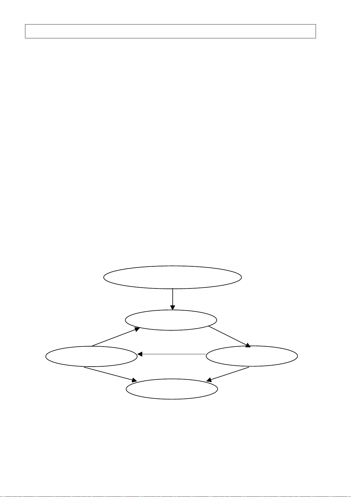
10. PROJECTOR OPERATION MODES
This section describes the Projector’s four basic operation modes.
10.1 Standby Mode
The Projector enters this mode when it is plugged into an AC outlet and the MAIN POWER
switch is turned ON.
The lamp does not light and the fans do not operate.
10.2 Power ON Mode
This mode is engaged when the POWER ON command is received and processed
normally in the Standby mode. The lamp is lighted and the fans start rotating. Images can
be projected in this mode.
10.3 Cool-Down Mode
This mode is engaged when the POWER OFF command is received and processed
normally in the Power ON mode.
The lamp goes out and the fans are rotated continuously to cool down the lamp.
To avoid the lamp is lighted again in short time, the POWER ON command is not accepted
during this mode.
The DLA-G3010 series, the Cool-Down Mode time is approximate 90 seconds. The lamp
goes out and the fans are rotated continuously during this mode to cool down the lamp.
The DLA-M2000 series, the Cool-Down Mode time is approximate 120 seconds. The lamp
goes out and the fans are rotated continuously during this mode to cool down the lamp.
After the mentioned time lapse, the unit automatically enters the Standby mode.
10.4 Emergency Mode
This mode is engaged when the projector malfunctions or is improperly operated.
The lamp and the fans are shut down and the MAIN POWER switch is turned OFF.
Non-operation status continues until the reset function is activated.
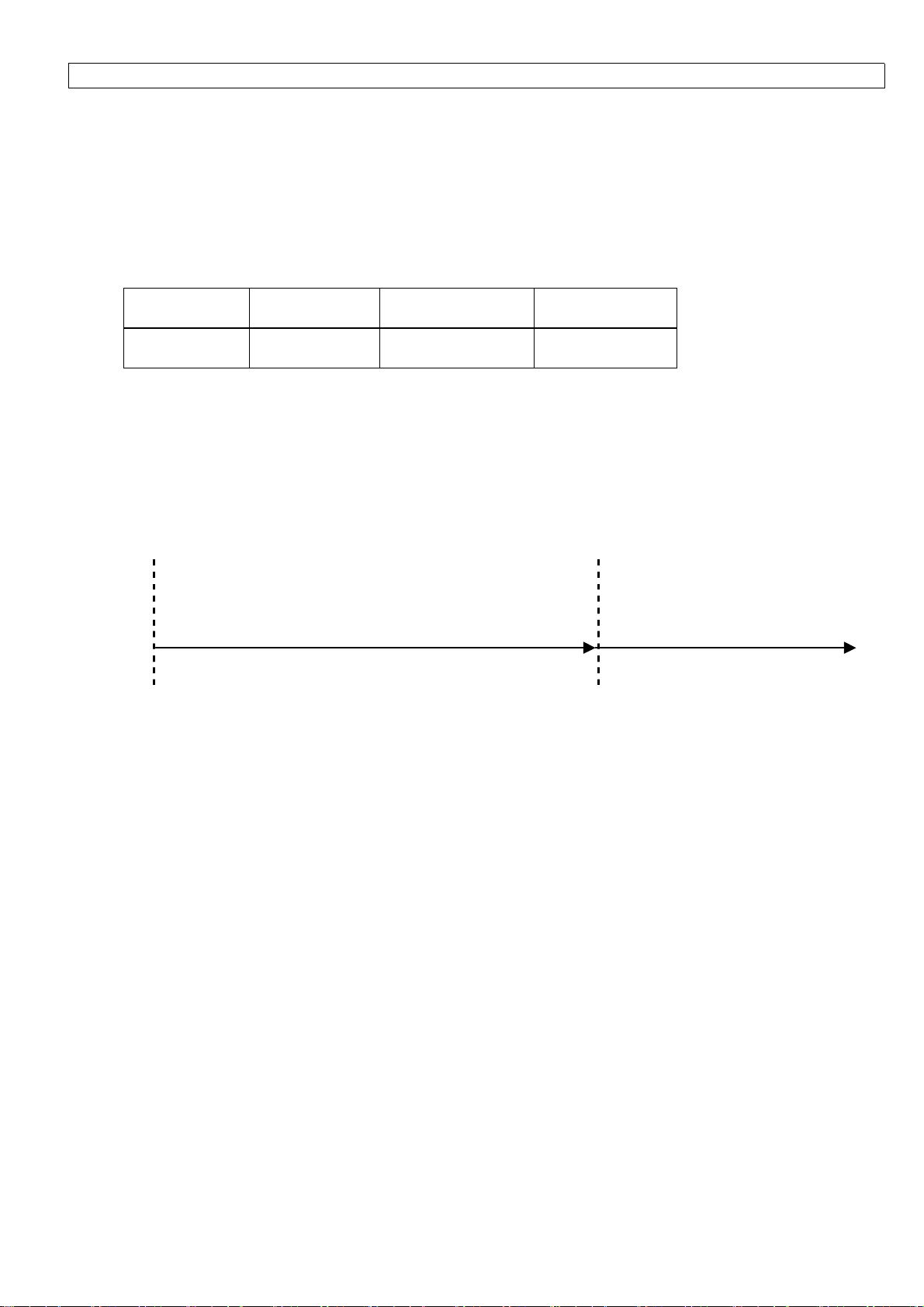
Switch ON the projector’s MAIN POWER
After 90 sec. Lamp cool-down
(DLA-G3010 Series)
After 120 sec. Lamp cool-down
(DLA-M2000 Series)
POWER OFF
Standby Mode
Sleep Time
Cool Down Mode Power ON Mode
Lamp not lit
Lamp shut down
Filter cover Filter cover
Fan lock
Emergency Mode Internal temp. abnormal
Fan lock
External temp. abnormal
Lamp shut down
* Note that the acceptance/non-acceptance condition of a command differs depending on the operation
mode.
12
Page 14
11. SOURCE
The input signals to projectors can be Computer Sources and Video Sources.
Although the specific signal names are not given to Computer Sources , these can be specified with the
combination of Frequency and Resolution.
Video Sources are as follows:
NTSC(480i)
PAL/SECAM
NTSC(480p)
PAL(625p)
DTV(720p)
HDTV(1035i)
HDTV(1080i)
11.1 Sources (Areas) and Source Numbers
When inputs via a composite / S-VIDEO/RGB
Source Source No. Source No. Source Source No. Source No.
(Character) (HEX) (Character) (HEX)
NTSC(480i) ‘00’ 30H 30H NTSC(480i) ‘80’ 38H 30H
When inputs via a YPbPr
PAL / SECAM ‘02’ 30H 32H PAL / SECAM ‘82’ 38H 32H
NTSC(480p) ‘04’ 30H 34H NTSC(480p) ‘84’ 38H 34H
PAL(625p) ‘05’ 30H 35H PAL(625p) ‘85’ 38H 35H
DTV(720p) ‘06’ 30H 36H DTV(720p) ‘86’ 38H 36H
HDTV(1035i) ‘07’ 30H 37H HDTV(1035i) ‘87’ 38H 37H
HDTV(1080i) ‘08’ 30H 38H HDTV(1080i) ‘88’ 38H 38H
Computer
Sources
No Signal ‘FF’ 46H 46H
RGB signals or YPbPr signal is fed to BNC input terminal , the different Source No is given even if the same
type of Source.
※ Note that the acceptance / non-acceptance of a command is differ depending on the Source
(Area) actually registered on the Projector.
‘F0’ 46H 30H No Signal ‘FF’ 46H 46H
13
Page 15

12. COMMANDS
This section describes the commands that can be used with the Projector.
◇ In the Communication Examples, the ID number registered on the Projector is represented as ‘1’ (31H).
This is the default setting.
◇ "CTLR" refers to transmissions from the external control unit and "DLA" refers to transmissions (Tally
(Response) Data) from the Projector.
◇ "Reply Time" refers to the maximum time required between command reception and return of Tally
(Response) Data. In other words, it refers to the maximum time that the external control unit must
wait for the Tally (Response) Data.
◇ For details on the different parameters, refer to 7. Parameters.
◇ Acceptance or non-acceptance of a command in each operation mode is indicated by "O" (accept) or
"X" (does not accept).
14
Page 16

12.1 HIDE :’U00’(55H 30H 30H)
Definition :Controls video signal muting
Command :’U00’(55H 30H 30H)
Parameter type :ON/OFF
Reply time :3seconds
Conditions :
Operation mode
X O X X
Communication Examples
#
◇ To turn HIDE ON
CTLR ‘!’ ‘1’ SP ‘U00’ SP ‘1’ CR
DLA ‘@’ ‘1’ SP ‘0’ CR
◇ When requesting current HIDE status (if HIDE status is ON)
CTLR ‘?’ ‘1’ SP ‘U00’ CR
DLA ‘@’ ‘1’ SP ‘0’ SP ‘1’ CR
◇ When trying to change HIDE status in emergency mode (turn ON)
CTLR ‘!’ ‘1’ SP ‘U00’ SP ‘1’ CR
DLA ‘@’ ‘1’ SP ‘A04’ CR
Standby mode Power ON mode Cool-down mode Emergency mode
15
Page 17

12.2 Horizontal Position :’U02’(55H 30H 32H)
Definition :Adjusts the horizontal position
Command : ‘U02’(55H 30H 32H)
Parameter type :Numeric,
Reply time :3seconds
Conditions :Except when there is no Source (Area) signal
Operation mode
Standby mode Power ON mode Cool-down mode Emergency mode
X O X X
Communication Examples
#
◇ When specifying "30" (decimal) as the horizontal position
CTLR ‘!’ ‘1’ SP ‘U02’ SP ‘001E’ CR
DLA ‘@’ ‘1’ SP ‘0’ CR
◇ When requesting current horizontal position data (if horizontal position is set to "-1")
CTLR ‘?’ ‘1’ SP ‘U02’ CR
DLA ‘@’ ‘1’ SP ‘0’ SP ‘FFFF’ CR
◇ When specifying the horizontal position, but the Source (Area) has no signal input
CTLR ‘!’ ‘1’ SP ‘U02’ SP ‘001E’ CR
DLA ‘@’ ‘1’ SP ‘A05’ CR
16
Page 18

12.3 Vertical Position :’U03’(55H 30H 33H)
Definition :Adjusts the vertical position
Command : ‘U03’(55H 30H 33H)
Parameter type :Numeric,
Reply time :3seconds
Conditions :Except when there is no Source (Area) signal
Operation mode
Standby mode Power ON mode Cool-down mode Emergency mode
X O X X
Communication Examples
#
◇ When specifying "5" (decimal) as the vertical position
CTLR ‘!’ ‘1’ SP ‘U03’ SP ‘0005’ CR
DLA ‘@’ ‘1’ SP ‘0’ CR
◇ When requesting current vertical position data (if vertical position is set to "16" (decimal))
CTLR ‘?’ ‘1’ SP ‘U03’ CR
DLA ‘@’ ‘1’ SP ‘0’ SP ‘0010’ CR
17
Page 19

12.4 Phase :’U04’(55H 30H 34H)
Definition :Adjusts the phase
Command : ‘U04’(55H 30H 34H)
Parameter type :Numeric
Reply time :3seconds
Conditions :Eexcept when there is no Source (Area) signal
Operation mode
Standby mode Power ON mode Cool-down mode Emergency mode
X O X X
Communication Examples
#
◇ When specifying "50" (decimal) as the phase adjust level
CTLR ‘!’ ‘1’ SP ‘U04’ SP ‘0032’ CR
DLA ‘@’ ‘1’ SP ‘0’ CR
◇ When requesting the current phase adjust level (if phase adjust level is set to "0" (decimal))
CTLR ‘?’ ‘1’ SP ‘U04’ CR
DLA ‘@’ ‘1’ SP ‘0’ SP ‘0000’ CR
18
Page 20

12.5 Tracking :’U05’(55H 30H 35H)
Definition :Adjusts tracking
Command :’U05’(55H 30H 35H)
Parameter type :Numeric
Reply time :3seconds
Conditions :Except when there is no Source (Area) signal
Operation mode
Standby mode Power ON mode Cool-down mode Emergency mode
X O X X
Communication Examples
#
◇ When specifying "50" (decimal) as tracking adjust level
CTLR ‘!’ ‘1’ SP ‘U05’ SP ‘0032’ CR
DLA ‘@’ ‘1’ SP ‘0’ CR
◇ When requesting current tracking adjust level data (if tracking adjust level is set to "0" (decimal))
CTLR ‘?’ ‘1’ SP ‘U05’ CR
DLA ‘@’ ‘1’ SP ‘0’ SP ‘0000’ CR
19
Page 21

12.6 Contrast :’U06’(55H 30H 36H)
Definition :Adjusts the contrast
Command :’U06’(55H 30H 36H)
Parameter type :Numeric,
Reply time :3seconds
Conditions :Except when there is no Source (Area) signal
Operation mode
Standby mode Power ON mode Cool-down mode Emergency mode
X O X X
Communication Examples
#
◇ When specifying "2" (decimal) as the contrast adjust level
CTLR ‘!’ ‘1’ SP ‘U06’ SP ‘0002’ CR
DLA ‘@’ ‘1’ SP ‘0’ CR
◇ When requesting current contrast adjust level data (if contrast adjust level is set to "0" (decimal))
CTLR ‘?’ ‘1’ SP ‘U06’ CR
DLA ‘@’ ‘1’ SP ‘0’ SP ‘0000’ CR
20
Page 22

12.7 Brightness :’U07’(55H 30H 37H)
Definition :Adjusts the brightness
Command :’U07’(55H 30H 37H)
Parameter type :Numeric,
Reply time :3seconds
Conditions :Except when there is no Source (Area) signal
Operation mode
Standby mode Power ON mode Cool-down mode Emergency mode
X O X X
Communication Examples
#
◇ When specifying "-2" (decimal) as the brightness adjust level
CTLR ‘!’ ‘1’ SP ‘U07’ SP ‘FFFE’ CR
DLA ‘@’ ‘1’ SP ‘0’ CR
◇ When requesting current brightness adjust level data (if brightness adjust level is set to
"0" (decimal))
CTLR ‘?’ ‘1’ SP ‘U07’ CR
DLA ‘@’ ‘1’ SP ‘0’ SP ‘0000’ CR
21
Page 23

12.8 Sharpness :’U08’(55H 30H 38H)
Definition :Adjusts the sharpness
Command :’U08’(55H 30H 38H)
Parameter type :Numeric,
Reply time :3seconds
Conditions :Video Sources (Areas)
Operation mode
Standby mode Power ON mode Cool-down mode Emergency mode
X O X X
Communication Examples
#
◇ When specifying "2" (decimal) as the sharpness
CTLR ‘!’ ‘1’ SP ‘U08’ SP ‘0002’ CR
DLA ‘@’ ‘1’ SP ‘0’ CR
◇ When requesting current sharpness adjust level data (if sharpness adjust level is set to "7"
(decimal))
CTLR ‘?’ ‘1’ SP ‘U08’ CR
DLA ‘@’ ‘1’ SP ‘0’ SP ‘0007’ CR
22
Page 24

12.9 Color :’U09’(55H 30H 39H)
Definition :Adjusts the color
Command :’U09’(55H 30H 39H)
Parameter type :Numeric,
Reply time :3seconds
Conditions :Video Sources (Areas)
Operation mode
Standby mode Power ON mode Cool-down mode Emergency mode
X O X X
Communication Examples
#
◇ When specifying "-2" (decimal) as the color adjust level
CTLR ‘!’ ‘1’ SP ‘U09’ SP ‘FFFE’ CR
DLA ‘@’ ‘1’ SP ‘0’ CR
◇ When requesting current color adjust level (if color adjust level is set to "0" (decimal))
CTLR ‘?’ ‘1’ SP ‘U09’ CR
DLA ‘@’ ‘1’ SP ‘0’ SP ‘0000’ CR
23
Page 25

12.10 Tint :’U0A’(55H 30H 41H)
Definition :Adjusts the tint
Command :’U0A’(55H 30H 41H)
Parameter type :Numeric,
Reply time :3seconds
Conditions :Video Sources (Areas)
Operation mode
Standby mode Power ON mode Cool-down mode Emergency mode
X O X X
Communication Examples
#
◇ When specifying "-2" (decimal) as the tint adjust level
CTLR ‘!’ ‘1’ SP ‘U0A’ SP ‘FFFE’ CR
DLA ‘@’ ‘1’ SP ‘0’ CR
◇ When requesting current tint adjust level data (if tint adjust level is set to "0" (decimal))
CTLR ‘?’ ‘1’ SP ‘U0A’ CR
DLA ‘@’ ‘1’ SP ‘0’ SP ‘0000’ CR
24
Page 26

12.11 Color Temperature :’U0B’(55H 30H 42H)
Definition :Adjusts the color temperature
Command :’U0B’(55H 30H 42H)
Parameter type :Special parameter (Refer to 7.3.4 Color Temperature Parameter.)
Reply time :3seconds
Conditions :Except when there is no Source (Area) signal
Operation mode
Standby mode Power ON mode Cool-down mode Emergency mode
X O X X
Communication Examples
#
◇ When specifying "MIDDLE" as the color temperature
CTLR ‘!’ ‘1’ SP ‘U0B’ SP ‘1’ CR
DLA ‘@’ ‘1’ SP ‘0’ CR
◇ When requesting current color temperature data (if color temperature is set to "LOW")
CTLR ‘?’ ‘1’ SP ‘U0B’ CR
DLA ‘@’ ‘1’ SP ‘0’ SP ‘0’ CR
25
Page 27

12.12 R-Gain :’U0C’(55H 30H 43H)
Definition :Adjusts the R-gain
Command :’U0C’(55H 30H 43H)
Parameter type :Numeric,
Reply time :3seconds
Conditions :Computer Sources (Areas)
Operation mode
Standby mode Power ON mode Cool-down mode Emergency mode
X O X X
Communication Examples
#
◇ When specifying "-2" (decimal) as the R-gain adjust level
CTLR ‘!’ ‘1’ SP ‘U0C’ SP ‘FFFE’ CR
DLA ‘@’ ‘1’ SP ‘0’ CR
◇ When requesting current R-gain adjust level data (if R-gain adjust level is set to "128" (decimal))
CTLR ‘?’ ‘1’ SP ‘U0C’ CR
DLA ‘@’ ‘1’ SP ‘0’ SP ‘0080’ CR
26
Page 28

12.13 G-Gain :’U0D’(55H 30H 44H)
Definition :Adjusts the G-gain
Command :’U0D’(55H 30H 44H)
Parameter type :Numeric,
Reply time :3seconds
Conditions :Computer Sources (Areas)
Operation mode
Standby mode Power ON mode Cool-down mode Emergency mode
X O X X
Communication Examples
#
◇ When specifying "-2" (decimal) as the G-gain adjust level
CTLR ‘!’ ‘1’ SP ‘U0D’ SP ‘FFFE’ CR
DLA ‘@’ ‘1’ SP ‘0’ CR
◇ When requesting current G-gain adjust level data (if G-gain adjust level is set to "128" (decimal))
CTLR ‘?’ ‘1’ SP ‘U0D’ CR
DLA ‘@’ ‘1’ SP ‘0’ SP ‘0080’ CR
27
Page 29

12.14 B-Gain :’U0E’(55H 30H 45H)
Definition :Adjusts the B-gain
Command :’U0E’(55H 30H 45H)
Parameter type :Numeric,
Reply time :3seconds
Conditions :Computer Sources (Areas)
Operation mode
Standby mode Power ON mode Cool-down mode Emergency mode
X O X X
Communication Examples
#
◇ When specifying "-2" (decimal) as the B-gain adjust level
CTLR ‘!’ ‘1’ SP ‘U0E’ SP ‘FFFE’ CR
DLA ‘@’ ‘1’ SP ‘0’ CR
◇ When requesting current B-gain adjust level data (if B-gain adjust level is set to "128" (decimal))
CTLR ‘?’ ‘1’ SP ‘U0E’ CR
DLA ‘@’ ‘1’ SP ‘0’ SP ‘0080’ CR
28
Page 30

12.15 POWER :’U0F’(55H 30H 46H)
Definition :Controls the power
Command :’U0F’(55H 30H 46H)
Parameter type :ON/OFF
Reply time :POWER ON transmission 100seconds(*1)
POWER OFF transmission 3seconds(*2)
Conditions :No query
Operation mode
Standby mode Power ON mode Cool-down mode Emergency mode
O O X X
Communication Examples
#
◇ When turning the Projector’s power ON
CTLR ‘!’ ‘1’ SP ‘U0F’ SP ‘1’ CR
DLA ‘@’ ‘1’ SP ‘0’ CR
*1
When the POWER ON command is received, the Projector returns the Tally (Response) Data after
completing all the POWER ON processing operations (lighting lamp, rotating fans, transmitting data,
etc.). In most cases, the Tally (Response) Data should be returned within 35 to 40 seconds.
If it takes more time to light up or re-try is done due to internal error , these operations takes maximum
around 100 seconds. (The Tally Data is returned within 100 seconds.)
*2
When the POWER OFF command is received during Power-ON mode, the Projector enters the
cool-down mode (DLA-G3010 series: for about 90 seconds, DLA-M2000L series: for about 120
seconds) and continue cooling (DLA-G20series: for about 120 seconds, DLA-M4000L series: for about
10 minutes).
After cool-down mode is completed, the Projector automatically enters the stand-by mode. (For
operation modes, refer to 10. Projector Operation Modes.)
POWER ON command cannot be accepted in the Cool-Down mode. If POWER ON is requested after
POWER OFF command is sent, firstly the current operation mode should be asked and then if Standby
Mode is confirmed, POWER ON command should be sent. (For the command to request the current
operation mode, refer to 12.41 Operation Mode Query.)
29
Page 31

12.16 MENU Auto OFF :’U10’(55H 31H 30H)
Definition :Controls the display menu auto-off function
Command :’U10’(55H 31H 30H)
Parameter type :Special parameter (Refer to 7.3.1 Menu Display Auto OFF Parameter.)
Reply time :3seconds
Conditions :
Operation mode
Standby mode Power ON mode Cool-down mode Emergency mode
O O O X
Communication Examples
#
◇ When specifying that the menu display is turned off automatically
CTLR ‘!’ ‘1’ SP ‘U10’ SP ‘1’ CR
DLA ‘@’ ‘1’ SP ‘0’ CR
◇ When requesting the current menu display auto-off setting (if menu display does not turn
off automatically)
CTLR ‘?’ ‘1’ SP ‘U10’ CR
DLA ‘@’ ‘1’ SP ‘0’ SP ‘0’ CR
30
Page 32

12.17 Line Display :’U11’(55H 31H 31H)
Definition :Sets the line source (area) display after changing input terminals
Command :’U11’(55H 31H 31H)
Parameter type :ON/OFF
Reply time :3seconds
Conditions :
Operation mode
Standby mode Power ON mode Cool-down mode Emergency mode
O O O X
Communication Examples
#
◇ When setting the line display to OFF
CTLR ‘!’ ‘1’ SP ‘U11’ SP ‘0’ CR
DLA ‘@’ ‘1’ SP ‘0’ CR
◇ When requesting the current line display setting (if the line display is set to ON)
CTLR ‘?’ ‘1’ SP ‘U11’ CR
DLA ‘@’ ‘1’ SP ‘0’ SP ‘1’ CR
31
Page 33

12.18 Sleep Time :’U12’(55H 31H 32H)
Definition :Sets the sleep time
Command :’U12’(55H 31H 32H)
Parameter type :(*)
Reply time :3seconds
Conditions :
Operation mode
Standby mode Power ON mode Cool-down mode Emergency mode
O O O X
The "Sleep time" function automatically turns off the projector power if the no-signal status continues for a
specified time.
*Available parameters
Sleep time can be set to any of the following:
15 min., 30 min., 60 min., and 0 min.
When the above times are represented as numerical parameters:
Character HEX
15min. ‘000F’ 30H 30H 30H 46H
30min. ‘001E’ 30H 30H 31H 45H
60min. ‘003C’ 30H 30H 33H 43H
0min. ‘0000’ 30H 30H 30H 30H
The sleep time function is disabled when the time is set to “0 min”.
#Tally (Response) data format to current sleep time query
@’ ‘1’ SP Normal Termination Status SP Parameter 1 SP Parameter 2 CR
‘
Parameter 1:Indicates the sleep time specified
(Refer to "Available parameters")
Parameter 2 :Indicates the remaining sleep time.
Parameter type is numeric.
# Communication Examples
◇ When specifying "30 min." as the sleep time
CTLR ‘!’ ‘1’ SP ‘U12’ SP ‘001E’ CR
DLA ‘@’ ‘1’ SP ‘0’ CR
◇ When requesting the current sleep time setting (if the sleep time is set to "15 min." and the
remaining time is 3 min.)
CTLR ‘?’ ‘1’ SP ‘U12’ CR
DLA ‘@’ ‘1’ SP ‘0’ SP ‘000F’ SP ‘0003’ CR
32
Page 34

12.19 Right/Left Reverse :’U17’(55H 31H 37H)
Definition :Reverses the image horizontally
Command :’U17’(55H 31H 37H)
Parameter type :ON/OFF
Reply time :3seconds
Conditions :
Operation mode
Standby mode Power ON mode Cool-down mode Emergency mode
O O O X
Communication Examples
#
◇ When reversing the image horizontally (Right /Left reverse)
CTLR ‘!’ ‘1’ SP ‘U17’ SP ‘1’ CR
DLA ‘@’ ‘1’ SP ‘0’ CR
◇ When requesting the current R/L reverse setting (if the image is not reversed horizontally)
CTLR ‘?’ ‘1’ SP ‘U17’ CR
DLA ‘@’ ‘1’ SP ‘0’ SP ‘0’ CR
33
Page 35

12.20 Top/Bottom Invert :’U18’(55H 31H 38H)
Definition :Inverts the image vertically
Command :’U18’(55H 31H 38H)
Parameter type :ON/OFF
Reply time :3seconds
Conditions :
Operation mode
Standby mode Power ON mode Cool-down mode Emergency mode
O O O X
Communication Examples
#
◇ When inverting the image vertically (Top/Bottom invert)
CTLR ‘!’ ‘1’ SP ‘U18’ SP ‘1’ CR
DLA ‘@’ ‘1’ SP ‘0’ CR
◇ When requesting the current Top/Bottom invert setting (if the image is not inverted vertically)
CTLR ‘?’ ‘1’ SP ‘U18’ CR
DLA ‘@’ ‘1’ SP ‘0’ SP ‘0’ CR
34
Page 36

12.21 Decoder :’U19’(55H 31H 39H)
Definition :Selects the color TV broadcast system
Command :’U19’(55H 31H 39H)
Parameter type :Special parameter (Refer to 7.3.3 Decoder Parameter.)
Reply time :3seconds
Conditions :Except when there is no Source (Area) signal
Operation mode
Standby mode Power ON mode Cool-down mode Emergency mode
X O X X
Communication Examples
#
◇ When selecting "NTSC" as the broadcast system
CTLR ‘!’ ‘1’ SP ‘U19’ SP ‘0’ CR
DLA ‘@’ ‘1’ SP ‘0’ CR
◇ When requesting the current broadcast system setting (if the broadcast system is set to PAL)
CTLR ‘?’ ‘1’ SP ‘U19’ CR
DLA ‘@’ ‘1’ SP ‘0’ SP ‘2’ CR
35
Page 37

12.22 Input Select :’U1A’(55H 31H 41H)
Definition :Selects the video input terminals
Command :’U1A’(55H 31H 41H)
Parameter type :Special parameter (Refer to 7.3.5 Input Select Parameter.)
Reply time :3seconds
Conditions :
Operation mode
Standby mode Power ON mode Cool-down mode Emergency mode
X O X X
Communication Examples
#
◇ When selecting "D-SUB" as the video input
CTLR ‘!’ ‘1’ SP ‘U1A’ SP ‘3’ CR
DLA ‘@’ ‘1’ SP ‘0’ CR
◇ When requesting the current video input setting (if the video input is selected)
CTLR ‘?’ ‘1’ SP ‘U1A’ CR
DLA ‘@’ ‘1’ SP ‘0’ SP ‘1’ CR
36
Page 38
12.23 Transfer Rate :’U1B’(55H 31H 42H)
Definition :Controls the transfer rate for RS-232C
Command :’U1B’(55H 31H 42H)
Parameter type :Special parameter(Refer to 7.3.2 Transfer Rate Parameter.)
Reply time :3seconds
Conditions :
Operation mode
Standby mode Power ON mode Cool-down mode Emergency mode
O O O X
* After this command has been received and processed correctly, the Tally (Response) Data is returned at
the new transfer rate.
Communication Examples
#
◇ When changing the transfer rate to "9600 bps" from the current setting of "19200 bps"
CTLR ‘!’ ‘1’ SP ‘U1B’ SP ‘0’ CR
DLA
"19200bps" until this point "9600bps" from here on
* The default transfer rate setting is "19200bps".
‘@’ ‘1’ SP ‘0’ CR
37
Page 39

12.24 Lamp Time :’U1C’(55H 31H 43H)
Definition :Reset/check the lamp operation
Command :’U1C’(55H 31H 43H)
Parameter type :(*)
Reply time :3seconds
Conditions :
Operation mode
△ When resetting
Standby mode Power ON mode Cool-down mode Emergency mode
O X X X
△ When requesting current time
Standby mode Power ON mode Cool-down mode Emergency mode
O O O X
Data Format
#
△ Reset data format
‘!’ ‘1’
SP ‘U1C’ SP Reset Parameter CR
(*)Reset parameter
Character HEX
‘[()]’
5BH 28H 29H 5DH
* Never issue the Reset command unless the lamp has been replaced with a new one.
△ Tally (Response) data format when requesting current time
‘@’ ‘1’ SP Normal Termination Status SP Parameter 1 SP Parameter 2 CR
(*)Parameter1
The Projector has an incremental counter which counts Lamp Operation Time at 1 time in
every 4 minutes.
Parameter 1 shows this counter value. The parameter type is "numeric".
Actual lamp operating time is obtained by converting the Parameter 1 value into signed
2-byte binary hexadecimal and dividing it by 15.
38
Page 40

(*)Parameter2
Parameter 2 shows whether the lamp replacement time is close or not,
based on the
following calculation:
(Lamp service life-100 hours )≦ Lamp operating time < Lamp service life
Character HEX
Lamp replacement time not close ‘0’ 30H
Lamp replacement time close ‘1’ 31H
Lamp life exceeded ‘2’ 32H
Communication Examples
#
◇ When requesting the current lamp operating time (if the lamp operating time is 150 hours)
CTLR ‘?’ ‘1’ SP ‘U1C’ CR
DLA ‘@’ ‘1’ SP ‘0’ SP ‘08CA’ SP ‘0’ CR
39
Page 41

12.25 ID :’U1D’(55H 31H 44H)
Definition :Sets the ID for the Projector
Command :’U1D’(55H 31H 44H)
Parameter type :Special parameter(Refer to 7.3.10 ID Parameter.)
Reply time :3seconds
Conditions :No query
Operation mode
Standby mode Power ON mode Cool-down mode Emergency mode
O O O X
* When this command is received and processed correctly, the Tally (Response) Data is returned with the
changed ID number.
Communication Examples
#
◇ When changing the ID to ‘7’ from the current setting of ‘1’
CTLR ‘!’ ‘1’ SP ‘U1D’ SP ‘7’ CR
DLA ‘@’ ‘7’ SP ‘0’ CR
Tally (Response) data is returned with New ID no.
40
Page 42

12.26 Volume :’U20’(55H 32H 30H)
Definition :Adjusts the audio volume level
Command :’U20’(55H 32H 30H)
Parameter type :Numeric,
Reply time :3seconds
Conditions :Except when there is no Source (Area) signal
Operation mode
Standby mode Power ON mode Cool-down mode Emergency mode
X O X X
Communication Example
#
◇ When setting the volume adjust level to "30"
CTLR ‘!’ ‘1’ SP ‘U20’ SP ‘001E’ CR
DLA ‘@’ ‘1’ SP ‘0’ CR
◇ When requesting the current volume adjust level setting (if the volume level is set to "5")
CTLR ‘?’ ‘1’ SP ‘U20’ CR
DLA ‘@’ ‘1’ SP ‘0’ SP ‘0005’ CR
41
Page 43

12.27 Quick Alignment :’U2A’(55H 32H 41H)
Definition :Controls the quick alignment function
Command :’U2A’(55H 32H 41H)
Parameter type :(*)
Reply time :3seconds
Conditions :Except when there is no Source (Area) signal
Normal Tally Data is returned when query.
Operation mode
Standby mode Power ON mode Cool-down mode Emergency mode
X O X X
Quick Alignment Parameter
*
Use only
◇ Quick alignment parameter
Character HEX
OFF parameter for ON/OFF.
OFF ‘0’ 30H
The Projector performs quick alignment processing after returning Normal Termination Status Tally
(Response) data. Therefore, after OFF command transmission, send the following command after waiting for
fixed time (about 3 seconds or more).
Communication Example
#
More than 3 sec
Possible to transmit next
command
CTLR '!' '1' SP 'U2A' SP '0' CR '?' '1' SP 'Z03' CR
DLA '@' '1' SP '0' CR
42
Page 44

12.28 Text Mode :’U2C’(55H 32H 43H)
Definition :Controls the legibility of screen text
Command :’U2C’(55H 32H 43H)
Parameter type :Special parameter(Refer to 7.3.7 Text Mode Parameter.)
Reply time :3seconds
Conditions :Computer Sources (Areas)
Operation mode
Standby mode Power ON mode Cool-down mode Emergency mode
X O X X
Communication Examples
#
◇ When setting the text mode to "Normal"
CTLR ‘!’ ‘1’ SP ‘U2C’ SP ‘0’ CR
DLA ‘@’ ‘1’ SP ‘0’ CR
◇ When requesting current text mode setting (if the text mode is set to "Text 1")
CTLR ‘?’ ‘1’ SP ‘U2C’ CR
DLA ‘@’ ‘1’ SP ‘0’ SP ‘1’ CR
43
Page 45

12.29 Resize :’U2D’(55H 32H 44H)
Definition :Controls expanded image
Command :’U2D’(55H 32H 44H)
Parameter type :Special parameter(Refer to 7.3.9 Resize Parameter.)
Reply time :3seconds
Conditions :Computer Sources (Areas)
Operation mode
Standby mode Power ON mode Cool-down mode Emergency mode
X O X X
Communication Examples
#
◇ When setting the resize function to 1:1
CTLR ‘!’ ‘1’ SP ‘U2D’ SP ‘0’ CR
DLA ‘@’ ‘1’ SP ‘0’ CR
◇ When requesting the current resize function setting (if the resize function is set to Full)
CTLR ‘?’ ‘1’ SP ‘U2D’ CR
DLA ‘@’ ‘1’ SP ‘0’ SP ‘1’ CR
44
Page 46

12.30 Aspect Change :’U2E’(55H 32H 45H)
Definition :Controls the aspect ratio of the projected image
Command :’U2E’(55H 32H 45H)
Parameter type :Special parameter(Refer to 7.3.8 Aspect Parameter.)
Reply time :3seconds
Conditions :Video Sources (Areas)
Operation mode
Standby mode Power ON mode Cool-down mode Emergency mode
X O X X
Communication Examples
#
◇ When setting the aspect ratio to "4:3"
CTLR ‘!’ ‘1’ SP ‘U2E’ SP ‘0’ CR
DLA ‘@’ ‘1’ SP ‘0’ CR
◇ When requesting the current aspect ratio setting(if the aspect ratio is set to "16:9")
CTLR ‘?’ ‘1’ SP ‘U2E’ CR
DLA ‘@’ ‘1’ SP ‘0’ SP ‘1’ CR
45
Page 47

12.31 Horizontal Frequency Query :’U3C’(55H 33H 43H)
Definition :Requests horizontal frequency of picture that is projected
Command :’U3C’(55H 33H 43H)
Parameter type :Numeric,
Reply time :3seconds
Conditions :Except when there is no Source (Area) signal
Operation mode
Standby mode Power ON mode Cool-down mode Emergency mode
X O X X
Communication Examples
#
◇ When requesting horizontal frequency (if horizontal frequency is 64.3kHz)
CTLR ‘?’ ‘1’ SP ‘U3C’ CR
DLA ‘@’ ‘1’ SP ‘0’ SP ‘0283’ CR
Note) Horizontal Frequency is 10 times of data to be returned from Projector. This example shows 283 in
hexadecimal, which is 643 in decimal. Horizontal Frequency of Projected image is 643/10 =
64.3kHz.
46
Page 48

12.32 Vertical Frequency Query :’U3D’(55H 33H 44H)
Definition :Requests vertical frequency of picture that is projected
Command :’U3D’(55H 33H 44H)
Parameter type :Numeric,
Reply time :3seconds
Conditions :Except when there is no Source (Area) signal
Operation mode
Standby mode Power ON mode Cool-down mode Emergency mode
X O X X
Communication Examples
#
◇ When requesting vertical frequency (if vertical frequency is 60Hz)
CTLR ‘?’ ‘1’ SP ‘U3D’ CR
DLA ‘@’ ‘1’ SP ‘0’ SP ‘003C’ CR
47
Page 49

12.33 Horizontal Resolution Query :’U3E’(55H 33H 45H)
Definition :Requests horizontal resolution of picture that is projected
Command :’U3E’(55H 33H 45H)
Parameter type :Numeric,
Reply time :3seconds
Conditions :Except when there is no Source (Area) signal
Operation mode
Standby mode Power ON mode Cool-down mode Emergency mode
X O X X
Communication Examples
#
◇ When requesting horizontal resolution (if horizontal resolution is 1280)
CTLR ‘?’ ‘1’ SP ‘U3E’ CR
DLA ‘@’ ‘1’ SP ‘0’ SP ‘0500’ CR
48
Page 50

12.34 Vertical Resolution Query :’U3F’(55H 33H 46H)
Definition :Requests vertical resolution of picture that is projected
Command :’U3F’(55H 33H 46H)
Parameter type :Numeric,
Reply time :3seconds
Conditions :Except when there is no Source (Area) signal
Operation mode
Standby mode Power ON mode Cool-down mode Emergency mode
X O X X
Communication Examples
#
◇ When requesting vertical resolution (if vertical resolution is 1024)
CTLR ‘?’ ‘1’ SP ‘U3F’ CR
DLA ‘@’ ‘1’ SP ‘0’ SP ‘0400’ CR
49
Page 51

12.35 Keystone(Correction of trapezoid distortion) :’U40’(55H 34H 30H)
Definition :Correction of Keystone
Command :’U40’(55H 34H 30H)
Parameter type :Numeric,
Reply time :3seconds
Conditions :
Operation mode
Standby mode Power ON mode Cool-down mode Emergency mode
X O X X
Communication Examples
#
◇ When specifying "0" (decimal) as keystone
CTLR ‘!’ ‘1’ SP ‘U40’ SP ‘0080’ CR
DLA ‘@’ ‘1’ SP ‘0’ CR
◇ When requesting the keystone (if the keystone is set to "0" (decimal))
CTLR ‘?’ ‘1’ SP ‘U40’ CR
DLA ‘@’ ‘1’ SP ‘0’ SP ‘0080’ CR
50
Page 52

12.36 Operation Mode Query :’Z03’(5AH 30H 33H)
Definition :Requests current operation mode
Command :’Z03’(5AH 30H 33H)
Parameter type :Special parameter(Refer to 7.3.6 Projector Operation Mode Parameter.)
Reply time :3seconds
Conditions :Query only
Operation mode
Standby mode Power ON mode Cool-down mode Emergency mode
O O O O
When the POWER OFF command is received in the Power ON mode, the Projector first enters
the Cool-Down mode, then automatically enters the Standby mode.
(For information on each operation mode, refer to 10. Projector Operation Modes.)
POWER ON command cannot be accepted in the Cool-Down mode. If POWER ON is requested after
POWER OFF command is sent, firstly the current operation mode should be asked and then if Standby
Mode is confirmed, POWER ON command should be sent.
# Communication Examples
◇ When requesting the current operation mode(if the Projector is in the standby mode)
CTLR ‘?’ ‘1’ SP ‘Z03’ CR
DLA ‘@’ ‘1’ SP ‘0’ SP ‘0000’ CR
51
Page 53

12.37 Source Query :’Z05’(5AH 30H 35H)
Definition :Asks for the Source (Area) setting actually assigned on the Projector.
Command :’Z05’(5AH 30H 35H)
Parameter type : (Refer to 11.1 Projector Sources and Source Numbers.)
Reply time :3seconds
Conditions :Query only
Operation mode
Standby mode Power ON mode Cool-down mode Emergency mode
X O X X
# Communication Example
◇ When requesting the current Source (Area) setting actually assigned on the Projector
(if Computer Sources is actually assigned)
CTLR '?' '1' SP 'Z05' CR
DLA '@' '1' SP '0' SP 'F0' CR
52
Page 54
12.38 Projector Model Query : ‘Z0A’(5AH 30H 41H)
Definition :Obtains projector model and software version information.
Command :’Z0A’(5AH 30H 41H)
Parameter type :(*)
Reply time :3seconds
Conditions :Query only
Operation mode
Standby mode Power ON mode Cool-down mode Emergency mode
O O O X
* Model status data format
◇ Requesting current projector model status
‘?’ ‘1’
Parameter: None
# Tally (response) data format to query
‘@’ ‘1’
Parameter: 12 byte ASCII characters are used for Model and Software version information.
MMMMMMMXXXXX
Software version
Model
Model
SP ‘Z0A’ CR
SP Normal Termination Status SP Parameter CR
HEX Definition
‘D03
――――
‘M2000
――
’
’
44H 30H 33H 2DH 2DH 2DH 2DH
4DH 32H 30H 30H 30H 2DH 2DH
DLA-G3010 Series Projector
DLA-M2000 Series Projector
# Communication Example
◇ When the projector is a M2000 series projector with software version 1.2.1
CTLR ‘?’ ‘1’ SP ‘Z0A’ CR
DLA ‘@’ ‘1’ SP ‘0’ SP ‘M2000--00121’ CR
53
Page 55

12.39 Switcher Selection : ‘W00’(57H 30H 30H)
Definition : Changes channels according to commands from the Switcher. When Projector receive
the command, Projector switches input terminal to RGB. And Source to be matched to
input switching number among presetted Sources is displayed.
When it is not set up or not being matched, the source inputted now is newly set up.
Command :’W00’(57H 30H 30H)
Parameter type :The Switcher’s input switching number. (Refer to 7.3.11 Switcher Number
Parameter.)
Reply time :3seconds
Conditions :
Operation mode
Standby mode Power ON mode Cool-down mode Emergency mode
X O X X
# Communication Examples
◇ When specifying Switcher 2 (if a channel specifying input switcher 2 exists.)
CTLR ‘!’ ‘1’ SP ‘W00’ SP ‘0002’ CR
DLA ‘@’ ‘1’ SP ‘0’ CR
◇ When requesting the current Switcher No. (if Switcher does not connected)
CTLR '?' '1' SP 'W00' CR
DLA '@' '1' SP '0' SP '0000' CR
54
Page 56

13. APPENDIX
13. 1 External Control Command List
Command Character HEX
Hide ‘U00’ 55H 30H 30H
Horizontal Position ‘U02’ 55H 30H 32H
Vertical Position ‘U03’ 55H 30H 33H
Phase ‘U04’ 55H 30H 34H
Tracking ‘U05’ 55H 30H 35H
Contrast ‘U06’ 55H 30H 36H
Brightness ‘U07’ 55H 30H 37H
Sharpness ‘U08’ 55H 30H 38H
Color ‘U09’ 55H 30H 39H
Tint ‘U0A’ 55H 30H 41H
Color Temperature ‘U0B’ 55H 30H 42H
R-Gain ‘U0C’ 55H 30H 43H
G-Gain ‘U0D’ 55H 30H 44H
B-Gain ‘U0E’ 55H 30H 45H
Power ‘U0F’ 55H 30H 46H
Menu Auto Off ‘U10’ 55H 31H 30H
Line Display ‘U11’ 55H 31H 31H
Sleep Time ‘U12’ 55H 31H 32H
Right/Left Reverse ‘U17’ 55H 31H 37H
Top/Bottom Invert ‘U18’ 55H 31H 38H
Decoder ‘U19’ 55H 31H 39H
Input Select ‘U1A’ 55H 31H 41H
Transfer Rate ‘U1B’ 55H 31H 42H
Lamp Time ‘U1C’ 55H 31H 43H
ID ‘U1D’ 55H 31H 44H
55
Page 57
Volume ‘U20’ 55H 32H 30H
Quick Alignment ‘U2A’ 55H 32H 41H
Text Mode ‘U2C’ 55H 32H 43H
Resize ‘U2D’ 55H 32H 44H
Aspect Change ‘U2E’ 55H 32H 45H
Horizontal Frequency Query 'U3C' 55H 33H 43H
Vertical Frequency Query 'U3D' 55H 33H 44H
Horizontal Resolution Query 'U3E' 55H 33H 45H
Vertical Resolution Query 'U3F' 55H 33H 46H
Keystone ‘U40’ 55H 34H 30H
Operation Mode Query ‘Z03’ 5AH 30H 33H
Source Query ‘Z05’ 5AH 30H 35H
Model Status ‘Z0A’ 5AH 30H 41H
Switcher Selection ‘W00’ 57H 30H 30H
56
Page 58

13. 2 RS-232C Port Pin Configuration
RS-232C Control Port
D-SUB 9-pin
Pin No. Signal Definition
(Male)
1
N/A
Not used
2 RxD(RD) Receive data
3 TxD(SD) Transmit data
4
N/A
Not used
5 GND GND
6
7
8
9
N/A
N/A
N/A
N/A
Not used
Not used
Not used
Not used
57
 Loading...