

Page 1
SUBWOOFER
CAISSON DE GRAVE
CS-AW8040
CS-AW8240
ENGLISH
FRANÇAISESPAŃOL
CS-AW8040 CS-AW8240
For Customer Use:
Enter below the Model No, and Serial
No, which is located either on the rear
or bottom of the speaker unit. Retain
this information for future reference.
Model No.
INSTRUCTION MANUAL
MANUEL D'INSTRUCTIONS
MANUAL DE INSTRUCCIONES
Serial No.
LVT1742-001A
Page 2
Thank you for purchasing the ARSENAL Car Stereo Speaker. These Speakers can be
mounted in the trunk of your vehicle. For the secure installation and perfect operation
of your speakers, please read the following carefully.
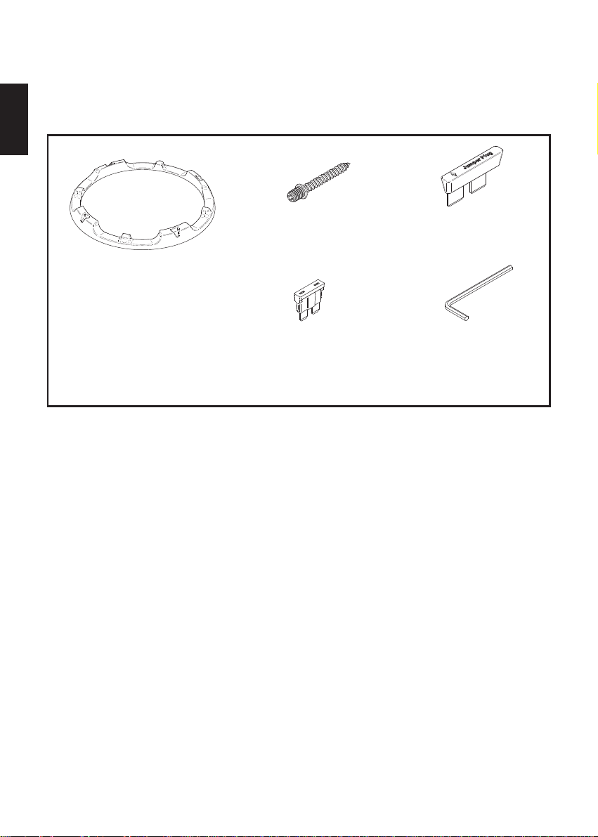
Parts
ENGLISH
3. Jump2. Screw x 10
1. Grille
4. Fuse (10A) x 2
For proper installation and use
1.Before connecting the speakers to the amplifier, confirm that the power has been
turned off. The click noise generated by the connection if the power is on may
damage the speakers.
2.The amplifier and speakers should be connected between corresponding terminals,
i.e. left to left, and right to right, as well as "+" to "+", and "–" to "–". Connection with
reversed polarity will degrade the quality of stereo reproduction.
3.Do not subject the speakers to excessive input. The power handling capacity of the
CS-AW8240/CS-AW8040 is 1000 watts (R.M.S. MUSIC POWER). Any excessive
input may damage the speakers.
4.The CS-AW8240/CS-AW8040 has an impedance of 2Ω,4Ω,8Ω. Make sure that the
output impedance of the amplifier's speaker terminal is rated at 2Ω,4Ω,8Ω.
5.When cleaning the speakers, use a soft cloth and wipe the surface gently. Do not
apply thinner or solvent.
6.Be sure to carefully follow the instructions for:
Cable Connections
Fuse Replacement
Switching the Impedance Selector
Subwoofer Mounting and Smart Trim Ring Installation
5. Hexagon socket
screw keys
Consult Page 19 of this Instruction Manual for details on these procedures.
- 2 -
Page 3
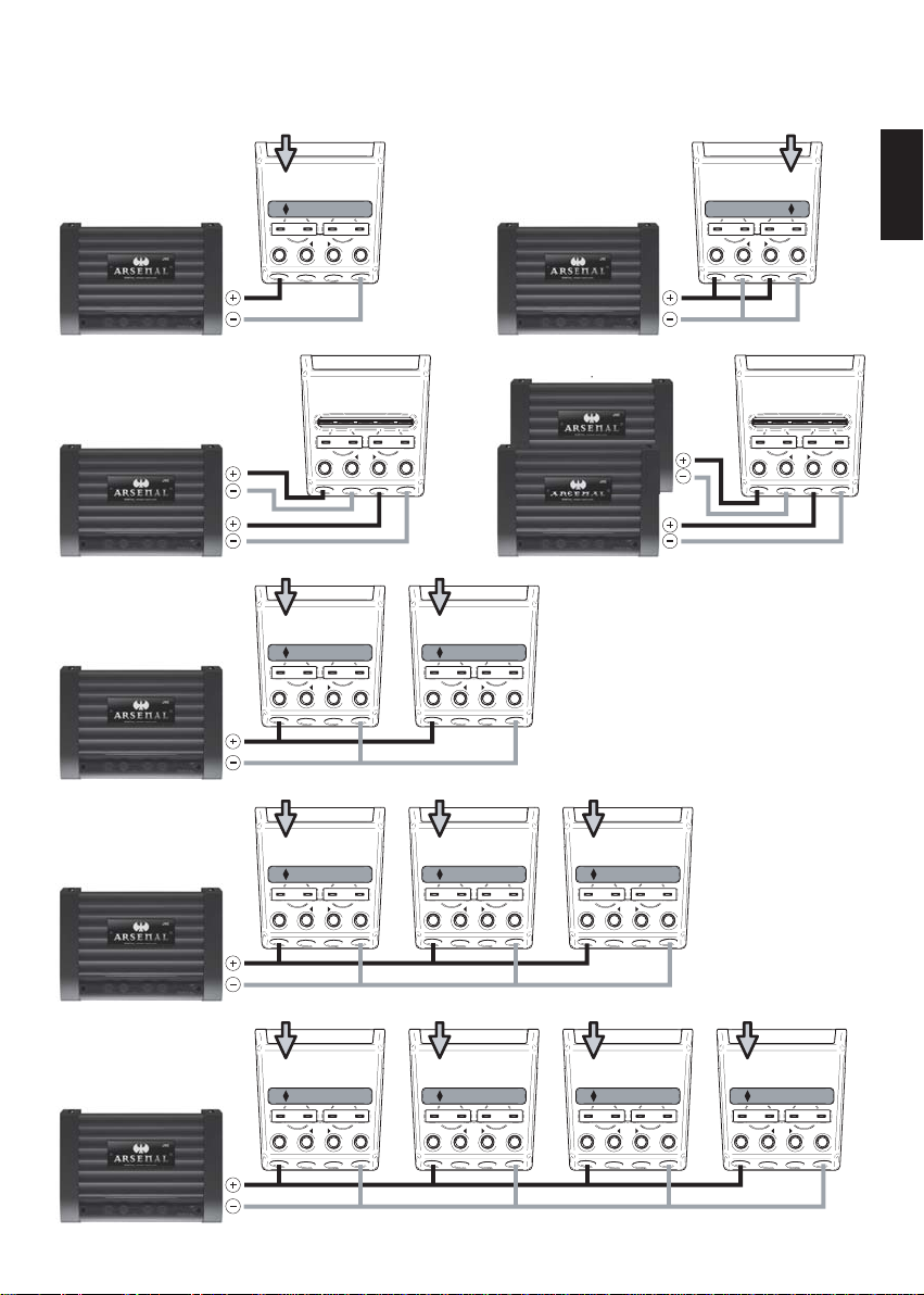
Dual 4 Ω Application Diagrams
1 Mono Amplifier
1 Subwoofer
Jumper set to Series
8Ω(4Ω+4Ω) Load
1 2ch Amplifier
1 Subwoofer
Jumper is Removed
4Ω Load
1 Mono Amplifier
2 Subwoofers
Jumper set to Series
Subwoofers wired in Parallel
4Ω Load
JUMPER
Mono
Stereo
4Ω 2-Chan
JUMPER
Mono
4Ω
JUMPER
1 Mono Amplifier
1 Subwoofer
SERIES PARALLEL
Jumper Plug
Input Bi-Amp Input
Only
-
+
+
-
Jumper set to Parallel
8Ω(4Ω+4Ω) Load
Mono
SERIES PARALLEL
Jumper Plug
Input Bi-Amp Input
Only
-
+
+
4Ω
4Ω4Ω8Ω4Ω
-
2Ω
*JUMPER is Removed *JUMPER is Removed
SERIES PARALLEL
Input Bi-Amp Input
Only
-
-
+ +
Bi-Amp Configuration 2 Mono Amplifiers
1 Subwoofer Jumper is Removed 4Ω Load
Mono
4Ω
SERIES PARALLEL
Input Bi-Amp Input
Only
-
+ +
Mono
4Ω
JUMPER
SERIES PARALLEL
Jumper Plug
Input Bi-Amp Input
Only
-
-
+
+
4Ω
4Ω 4Ω 4Ω
8Ω 8Ω
SERIES PARALLEL
Jumper Plug
Input Bi-Amp Input
Only
-
+
+
-
ENGLISH
-
1 Mono Amplifier
3 Subwoofers
Jumper set to Series
Subwoofers wired in Parallel
2.6Ω Load
1 Mono Amplifier
4 Subwoofers
Jumper set to Series
Subwoofers wired in Parallel
2Ω Load
JUMPER
Mono
2.6Ω
JUMPER
Mono
2Ω
SERIES PARALLEL
Jumper Plug
Input Bi-Amp Input
Only
-
+
+
4Ω
4Ω
8Ω
SERIES PARALLEL
Jumper Plug
Input Bi-Amp Input
Only
-
+
+
4Ω
4Ω
8Ω
JUMPER
SERIES PARALLEL
Jumper Plug
Input Bi-Amp Input
-
Only
-
+
+
4Ω8Ω4Ω
JUMPER
SERIES PARALLEL
Jumper Plug
Input Bi-Amp Input
-
Only
-
+
4Ω8Ω4Ω
+
JUMPER
SERIES PARALLEL
Jumper Plug
Input Bi-Amp Input
-
-
Only
-
-
+
+
4Ω8Ω4Ω
JUMPER
SERIES PARALLEL
Jumper Plug
Input Bi-Amp Input
Only
-
+
+
JUMPER
SERIES PARALLEL
-
Input Bi-Amp Input
+
4Ω8Ω4Ω 4Ω8Ω4Ω
Jumper Plug
Only
-
+
-
- 3 -
Page 4
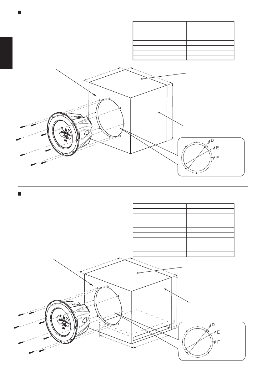
To install the sealed enclosure
When the speaker cannot be attached in the car, make the sealed enclosure as recommended in the table below—20 mm (3/4 inch) MDF is also
recommended for the enclosure materials.
ENGLISH
Front & Rear Bae Boards (x 2)
C
CS-AW8040 CS-AW8240
A 15-13/32 inch (391.7 mm)
B 15-13/32 inch (391.7 mm)
C
11-29/32 inch (302.8 mm) 12-13/32 inch (315.5 mm)
D
9-4/32 inch (232 mm) 10-14/32 inch (275.9 mm)
E
9-23/32 inch (247 mm) 11-10/32 inch (295 mm)
F
4/32 inch (3 mm) 4/32 inch (3 mm)
3
1.64 ft
(0.046 m3) 1.94 ft3 (0.055 m3)
G
B
16-13/32 inch (417.1 mm)
16-13/32 inch (417.1 mm)
Top & Bottom Sides (x 2)
G : Internal Volume
A
Left & Right Sides (x 2)
* Screw: Dia. 4mm x 50mm (x 8) (supplied)
Mounting Hole
Dimension
To install the ported enclosure
When the speaker cannot be attached in the car, make the sealed enclosure as recommended in the table below—20 mm (3/4 inch) MDF is also
recommended for the enclosure materials.
Front & Rear Bae Boards (x 2)
C
CS-AW8040 CS-AW8240
A
14-13/32 inch (366.3 mm) 14-29/32 inch (379 mm)
B
18-13/32 inch (467.9 mm) 19-13/32 inch (493.3 mm)
C
14-13/32 inch (366.3 mm) 15-13/32 inch (391.7 mm)
D
9-23/32 inch (247 mm) 10-14/32 inch (275.9 mm)
E
9-23/32 inch (247 mm) 11-10/32 inch (295 mm)
F
4/32 inch (3 mm) 4/32 inch (3 mm)
G
1 inch (25.4 mm) 1 inch (25.4 mm)
H
13 inch (330.2 mm) 14 inch (355.6 mm)
I
13-19/32 inch (345.4 mm) 13-16/32 inch (342.9 mm)
3
2.22 ft
(0.063 m3) 2.59 ft3 (0.073 m3)
J
B
Top & Bottom Sides (x 2)
J : Internal Volume
A
Left & Right Sides (x 2)
G
* Screw: Dia. 4mm x 50mm (x 8) (supplied)
I
- 4 -
H
Mounting Hole
Dimension
Page 5
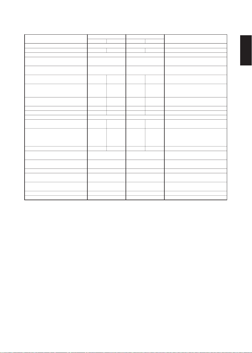
Nominal Impedance (Ω)
Displacement (Liter)
Hole Cutout Diameter (inch)
(mm)
Mounting Depth (inch)
(mm)
Re (Ω) Re : DC voice coil resistance
BL (T.M)
Vas (Liter)
Vas (CuFt)
D (mm) D : Effective cone diameter
Qms
Qes
Pe [max.] (W)
Xmax.(mm)
Freq.Responce (Hz)
Magnet Mass (oz)
(g)
Voice Coil(Aluminum)Dia.(inch)
(mm)
Hvc (mm) Hvc : Voice coil Height
Hag (mm) Hag : Gap Height
parallel
82.52 dB
Dia. 9 - 6/32 inch
1.98 Ω 7.81 Ω 7.87 Ω1.99 Ω
7.69 15.19 17.478.73
19.4 L 19.9 L 46.1 L46.04 L
0.69 ft
128.943 g 126.267 g 137.381 g137.361 g
39.5 Hz 39.4 Hz 35.5 Hz35.5 Hz
9.244 9.295 8.4018.404
1.068 1.057 0.790.799
0.957 0.948 0.7220.73
Dia. 3 - 5/32 inch
( 80.54 mm )
series seriesparallel
4Ω + 4Ω 4Ω + 4Ω
82.65 dB 86.19 dB86.14 dB
3
0.138 ft
( 233 mm )
6 - 28/32 inch
( 175 mm )
3
0.7 ft
Dia. 197.5 mm
1000 W
17.05 mm 17.05 mm
23 ~500 Hz
75.52 oz
( 2140.95 g )
44.1 mm
10 mm
CS-AW8240CS-AW8040
Dia. 10 - 29/32 inch
( 277 mm )
7 - 23/32 inch
( 195.8 mm )
3
1.63 ft
Dia. ( 241.5 mm
Dia. 3 - 5/32 inch
( 80.54 mm )
0.202 ft
3
1.63 ft
1000 W
20 ~500 Hz
103.24 oz
( 2926.8 g )
44.1 mm
10 mm
SPL : Sound pressure levelSPL (dB,1W/1M)
3
BL : Product of Flux density and
Effective Voicecoil-wire length
Vas : Volume of air equal to the driver
compliance
3
Me : Effective massMe (g)
Fs : Driver free air resonanceFs (Hz)
Qms : Q of driver at Fs considering
only non-electrical resistance
Qes : Q of driver at Fs considering
only electrical resistance
Qts : Total Q of driver at FsQts
Pe[max.] : Maximum continuous input
power
Xmax. : Maximum effective voicecoil
travel without distortion
NOTESParameters
ENGLISH
- 5 -
Page 6

Nous vous remercions pour I'achat d'un haut-parleur auto stéréo de ARSENAL dans
le coffre de votre véhicule. Pour un montage sûr et un fonctionnement parfait de ce
haut-parleur, il est conseillé de lire attentivement ce qui suit.
Parts
FRANÇAIS
1. Grille
4. Fuse (10A) x 2
Montage et utilisation corrects
1.Vérifier que l'alimentation est coupée avant de raccorder les haut-parleurs à
l'amplificateur. Les craquements produits par le raccordement lors que l'alimentation
est fournie peuvent endomma ger les haut-parleurs.
2.Raccorder les bornes correspondantes de l’amplificateur et les haut-parleurs,
c'est-à-dire, gauche à gauche, droit à droite, de même que “+” à “+” et “–” à “–”. Un
raccordement effectué en inversant les polarités réduira la qualité de la reproduction
sonore stéréo-phonique.
3.Ne pas appliquer un niveau d'entrée excessif aux haut-parleurs. La puissance
d'entrée admissible pour les haut-parleurs CS-AW8240/CS-AW8040 est de 1000
watts (puissance musicale R.M.S.). Tout signal d'entrée excessif risque de les
endommager.
4.Les haut-parleurs CS-AW8240/CS-AW8040 ont une impédance de 2Ω,4Ω,8Ω. ll faut
par conséquent s'assurer que l'impédance de sortie aux bornes de haut-parleur de
l'amplificateur soit aussi de 2Ω,4Ω,8Ω.
5.Nettoyer le haut-parleur en le frottant légèrement à l'aide d'un chiffon doux. Ne
jamais utiliser de solvants ni de détergents.
6.Veuillez suivre attentivement les instructions suivantes pour:
Connections de Câble
Remplacement de Fusible
Changement de la Sélection d'Impédance
Montage du Subwoofer et Installation Pratique de la Moulure de Finition
Consultez la Page 19 de ce Manuel d'Instruction pour les détails de cesprocédures.
- 6 -
3. Jump2. Screw x 10
5. Hexagon socket
screw keys
Page 7

Diagrammes d’application duale 4Ω
1 amplificateur mono
1 (un) caisson de basse
Cavalier branché en Série
Impédance de charge de
8Ω(4Ω+4Ω)
Mono
1 amplificateur mono
1 (un) caisson de basse
Cavalier branché en Parallèle
Impédance de charge de 8Ω(4Ω+4Ω)
Stereo
1 amplificateur mono
2 (deux) caissons de basse
Cavalier branché en Série
Subwoofers wired in Parallel
Impédance de charge de 4Ω
Mono
JUMPER
SERIES PARALLEL
Jumper Plug
Input Bi-Amp Input
Only
-
+
+
*JUMPER is Removed
SERIES PARALLEL
Input Bi-Amp Input
+ +
4Ω 2-Chan
JUMPER
SERIES PARALLEL
Jumper Plug
Input Bi-Amp Input
Only
-
+
+
4Ω
8Ω 8Ω
4Ω
-
Only
-
-
JUMPER
SERIES PARALLEL
Jumper Plug
Input Bi-Amp Input
-
4Ω 4Ω 4Ω
Only
-
+
+
1 amplificateur mono
1 (un) caisson de basse
Cavalier branché en Parallèle
Impédance de charge de
8Ω(4Ω+4Ω)
Configuration en double amplification
2 amplificateurs mono
1 (un) caisson de basse Cavalier débranché
Impédance de charge de 4Ω
SERIES PARALLEL
Input Bi-Amp Input
+
Mono
4Ω2Ω4Ω4Ω8Ω4Ω
*JUMPER is Removed
Mono
4Ω
Mono
4Ω
-
JUMPER
Jumper Plug
Only
-
-
+
SERIES PARALLEL
Input Bi-Amp Input
Only
-
+ +
FRANÇAIS
-
1 amplificateur mono
3 (trois) caissons de basse
Cavalier branché en Série
Subwoofers wired in Parallel
Impédance de charge de 2.6Ω
1 amplificateur mono
4 (quatre) caissons de basse
Cavalier branché en Série
Subwoofers wired in Parallel
Impédance de charge de 2Ω
JUMPER
Mono
2.6Ω
JUMPER
Mono
2Ω
SERIES PARALLEL
Jumper Plug
Input Bi-Amp Input
Only
-
+
+
4Ω
4Ω
8Ω
SERIES PARALLEL
Jumper Plug
Input Bi-Amp Input
Only
-
+
+
4Ω
4Ω
8Ω
JUMPER
SERIES PARALLEL
Jumper Plug
Input Bi-Amp Input
-
Only
-
+
+
4Ω8Ω4Ω
JUMPER
SERIES PARALLEL
Jumper Plug
Input Bi-Amp Input
-
Only
-
+
4Ω8Ω4Ω
+
JUMPER
SERIES PARALLEL
Jumper Plug
Input Bi-Amp Input
-
-
Only
-
-
+
+
4Ω8Ω4Ω
JUMPER
SERIES PARALLEL
Jumper Plug
Input Bi-Amp Input
Only
-
+
+
JUMPER
SERIES PARALLEL
-
Input Bi-Amp Input
+
4Ω8Ω4Ω 4Ω8Ω4Ω
Jumper Plug
Only
-
+
-
- 7 -
Page 8

Pour installer l’enceinte hermétique
Si le haut-parleur ne peut pas être xé directement dans cette voiture, fabriquez une enceinte hermétique de façon recommandéeà l’aide des
spécications données dans le tableau ci-dessous; le
MDF—20 mm (3/4 pouce) est recommandé pour le matériau
de l’enceinte.
CS-AW8040 CS-AW8240
A 15-13/32 inch (391.7 mm)
B 15-13/32 inch (391.7 mm)
C
11-29/32 inch (302.8 mm) 12-13/32 inch (315.5 mm)
D
9-4/32 inch (232 mm) 10-14/32 inch (275.9 mm)
E
9-23/32 inch (247 mm) 11-10/32 inch (295 mm)
F
4/32 inch (3 mm) 4/32 inch (3 mm)
3
1.64 ft
(0.046 m3) 1.94 ft3 (0.055 m3)
G
16-13/32 inch (417.1 mm)
16-13/32 inch (417.1 mm)
Écrans acoustiques avant et arrière (x 2)
C
B
Faces supérieure et
inférieure (x 2)
FRANÇAIS
G : Volume interne
A
Faces gauche et
droite (x 2)
* Vis: Dia. 4mm x 50mm (x 8) (fournis)
Faces gauche
et droite (x 2)
Pour installer l’enceinte hermétique
Si le haut-parleur ne peut pas être xé directement dans cette voiture, fabriquez une enceinte hermétique de façon recommandéeà l’aide des
spécications données dans le tableau ci-dessous; le
MDF—20 mm (3/4 pouce) est recommandé pour le matériau
de l’enceinte.
Écrans acoustiques avant et arrière (x 2)
C
CS-AW8040 CS-AW8240
A
14-13/32 inch (366.3 mm) 14-29/32 inch (379 mm)
B
18-13/32 inch (467.9 mm) 19-13/32 inch (493.3 mm)
C
14-13/32 inch (366.3 mm) 15-13/32 inch (391.7 mm)
D
9-23/32 inch (247 mm) 10-14/32 inch (275.9 mm)
E
9-23/32 inch (247 mm) 11-10/32 inch (295 mm)
F
4/32 inch (3 mm) 4/32 inch (3 mm)
G
1 inch (25.4 mm) 1 inch (25.4 mm)
H
13 inch (330.2 mm) 14 inch (355.6 mm)
I
13-19/32 inch (345.4 mm) 13-16/32 inch (342.9 mm)
3
2.22 ft
(0.063 m3) 2.59 ft3 (0.073 m3)
J
B
Faces supérieure et
inférieure (x 2)
J : Volume interne
A
Faces gauche et
droite (x 2)
Faces gauche
et droite (x 2)
* Vis: Dia. 4mm x 50mm (x 8) (fournis)
G
I
H
- 8 -
Page 9

Paramètres
Impédance nominale (Ω)
SPL (dB,1W/1M) SPL : Niveau de pression sonore
Déplacement (Liter)
Diamètre du tuou de découpe (
Profondeur de montage (pouces)
(mm)
Re (Ω)
BL (T.M)
Vas (Iitre)
Vas (CuFt)
D (mm) D : Diamètre effectif du cône
Fs (Hz)
Qms
Qes
parallel
4Ω + 4Ω 4Ω + 4Ω
82.65 dB 86.19 dB86.14 dB
0.138 ft
Dia. 9 - 6/32 inch
( 233 mm )
6 - 28/32 inch
( 175 mm )
pouces)
(mm)
82.52 dB
1.98 Ω 7.81 Ω 7.87 Ω1.99 Ω
7.69 15.19 17.478.73
19.4 L 19.9 L 46.1 L46.04 L
3
0.69 ft
128.943 g 126.267 g 137.381 g137.361 g
Dia. 197.5 mm
39.5 Hz 39.4 Hz 35.5 Hz35.5 Hz
9.244 9.295 8.4018.404
1.068 1.057 0.790.799
series seriesparallel
3
0.7 ft
0.957 0.948 0.7220.73
Pe [max.] (W)
Xmax. (mm)
Réponse en fréquence (Hz)
Masse de l’aimant (once)
(g)
Diamètre de la bobine mobile (
Hvc (mm) Hvc : Hauteur de la bobine mobile
Hag (mm) Hvc : Hauteur de la bobine mobile
pouces)
(mm)
1000 W
17.05 mm 17.05 mm
23 ~500 Hz
75.52 oz
( 2140.95 g )
Dia. 3 - 5/32 inch
( 80.54 mm )
44.1 mm
10 mm
CS-AW8240CS-AW8040
Dia. 10 - 29/32 inch
( 277 mm )
7 - 23/32 inch
( 195.8 mm )
3
1.63 ft
Dia. 241.5 mm
Dia. 3 - 5/32 inch
( 80.54 mm )
0.202 ft
3
1.63 ft
1000 W
20 ~500 Hz
103.24 oz
( 2926.8 g )
44.1 mm
10 mm
REMARQUES
3
Re : Résistance de la bobine mobile
en CC
BL : Produit de la densité de flux et de
la longueur efficace de fil de la bobine
mobile
Vas : Volume d'air égal à la conformité
de l'excitateur
3
Me : Masse effectiveMe (g)
Fs : Résonance à l'air libre de
l'excitateur
Qms : Q de l'excitateur à Fs considérant
uniquement la résistance non-électrique
Qes : Q de l'excitateur à Fs considérant
uniquement la résistance électrique
Qts : Q total de l'excitateur à FsQts
Pe[max.] : Puissance d'entrée
continue maximum
Xmax. : Déplacement effectif maximum
de la bobine mobile sans distorsion
FRANÇAIS
- 9 -
Page 10

Le agradecemos la adquisición del Altavoz Estereofónico para Automóvil de
ARSENAL. Para efectuar una instalación segura y para que el altavoz funcione
correctamente, lea detenidamente las siguientes instrucciones.
Parts
3. Jump2. Screw x 10
1. Grille
ESPAŃOL
4. Fuse (10A) x 2
Instalación y uso correctos
1.Antes de conectar los altavoces con el amplificador, confirme que esté cortada la
alimentación eléctrica. El ruido producido al realizar la conexión con la alimentación
conectada puede causar daños en los altavoces.
2.Deben conectares los terminales correspondientes del amplificador y de los
altavoces, es decir izquierdo a izquierdo y derecho a derecho,asi co mo “+” a “+” y
“–” a “–”. Si las polaridades se co nectan inversamente, la reproducción este
reofónica se deteriorará.
3.No someta los altavoces a una entrada excesiva. La capacidad máxima de los
CS-AW8240/CS-AW8040 es de 1000 votios (POTENCIA MUSICAL R.M.S.). Una
entra da excesiva dañará los altavoces.
4.Los CS-AW8240/CS-AW8040 tienen 2Ω,4Ω,8Ω de impedancia. Asegúrese de que
la impe dancia de salida del terminal para altavoces de amplificador sea de 2Ω, 4Ω
,8Ω.
5.Cuando limpie los altavoces, utilice un paño suave y frote la superficie con cuidado.
No aplique solventes ni diluyentes.
6.Asegurese de seguir cuidadosamente las instrucciones para:
Conecciones de Cable
Reemplazo de fucible
Cambiando el Selector de Resistencia
Instalar el subwoofer y la moldura del anillo
5. Hexagon socket
screw keys
Consulte la Page 19 de este Manual de Instrucciones para los detalles de estos
procedimientos.
- 10 -
Page 11

Diagramas de Aplicasion Dual 4Ω
1 amplificador monofónico
1(un) bajo
Puente fijado en serie
Carga a 8Ω(4Ω+4Ω)
Amplificador 1,2 ch
1(un) bajo
Se quita el puente
Carga a 4Ω
1 amplificador monofónico
2 (Dos) bajos
Puente fijado en serie
Subwoofers wired in Parallel
Carga a 4Ω
JUMPER
Mono
Stereo
4Ω 2-Chan
JUMPER
Mono
4Ω
JUMPER
1 amplificador monofónico
1(un) bajo
SERIES PARALLEL
Jumper Plug
Input Bi-Amp Input
Only
-
+
+
-
Puente fijado en Paralelo
Carga a 8Ω(4Ω+4Ω)
Mono
SERIES PARALLEL
Jumper Plug
Input Bi-Amp Input
Only
-
+
+
4Ω
4Ω4Ω8Ω4Ω
-
2Ω
*JUMPER is Removed *JUMPER is Removed
SERIES PARALLEL
Input Bi-Amp Input
Only
-
-
+ +
Configuracion Bi-Amplificada
2 amplificadores monofónicos
1(un) bajo Se quita el puente Carga a 4Ω
Mono
4Ω
SERIES PARALLEL
Input Bi-Amp Input
Only
-
+ +
Mono
4Ω
JUMPER
SERIES PARALLEL
Jumper Plug
Input Bi-Amp Input
Only
-
-
+
+
4Ω
4Ω 4Ω 4Ω
8Ω 8Ω
SERIES PARALLEL
Jumper Plug
Input Bi-Amp Input
Only
-
+
+
-
-
ESPAŃOL
1 amplificador monofónico
3 (Tres) bajos
Puente fijado en serie
Subwoofers wired in Parallel
Carga a 2.6Ω
1 amplificador monofónico
4 (Cuatro) bajos
Puente fijado en serie
Subwoofers wired in Parallel
Carga a 2Ω
JUMPER
Mono
2.6Ω
JUMPER
Mono
2Ω
SERIES PARALLEL
Jumper Plug
Input Bi-Amp Input
Only
-
+
+
4Ω
4Ω
8Ω
SERIES PARALLEL
Jumper Plug
Input Bi-Amp Input
Only
-
+
+
4Ω
4Ω
8Ω
JUMPER
SERIES PARALLEL
Jumper Plug
Input Bi-Amp Input
-
Only
-
+
+
4Ω8Ω4Ω
JUMPER
SERIES PARALLEL
Jumper Plug
Input Bi-Amp Input
-
Only
-
+
4Ω8Ω4Ω
+
JUMPER
SERIES PARALLEL
Jumper Plug
Input Bi-Amp Input
-
-
Only
-
-
+
+
4Ω8Ω4Ω
JUMPER
SERIES PARALLEL
Jumper Plug
Input Bi-Amp Input
Only
-
+
+
JUMPER
SERIES PARALLEL
-
Input Bi-Amp Input
+
4Ω8Ω4Ω 4Ω8Ω4Ω
Jumper Plug
Only
-
+
-
- 11 -
Page 12

Para instalar la caja sellada
Cuando el altavoz no se pueda instalCuando el altavoz no se pueda instalCuando el altavoz no se pueda instalusar MDF—20 mm (3/4 pulg.) como
material para la caja.
CS-AW8040 CS-AW8240
A 15-13/32 inch (391.7 mm)
B 15-13/32 inch (391.7 mm)
C
11-29/32 inch (302.8 mm) 12-13/32 inch (315.5 mm)
D
9-4/32 inch (232 mm) 10-14/32 inch (275.9 mm)
E
9-23/32 inch (247 mm) 11-10/32 inch (295 mm)
F
4/32 inch (3 mm) 4/32 inch (3 mm)
3
1.64 ft
(0.046 m3) 1.94 ft3 (0.055 m3)
G
16-13/32 inch (417.1 mm)
16-13/32 inch (417.1 mm)
Pantallas acústicas delantera y trasera (x 2)
C
B
Lados superior e
inferior (x 2)
G : El Volumen interior
A
ESPAŃOL
Lados izquierdo y
derecho (x 2)
* Tcrnillo: Dia. 4mm x 50mm (x 8) (suministrado)
Para instalar la caja sellada
Lados superior e inferior (x 2)Cuando el altavoz no se pueda instalar en el automóvil, construya la caja sellada recomendada en la tablade
abajo—Asimismo, serecomienda usar
MDF—20 mm(3/4 pulg.) como material para la caja.
Pantallas acústicas delantera y trasera (x 2)
C
CS-AW8040 CS-AW8240
A
14-13/32 inch (366.3 mm) 14-29/32 inch (379 mm)
B
18-13/32 inch (467.9 mm) 19-13/32 inch (493.3 mm)
C
14-13/32 inch (366.3 mm) 15-13/32 inch (391.7 mm)
D
9-23/32 inch (247 mm) 10-14/32 inch (275.9 mm)
E
9-23/32 inch (247 mm) 11-10/32 inch (295 mm)
F
4/32 inch (3 mm) 4/32 inch (3 mm)
G
1 inch (25.4 mm) 1 inch (25.4 mm)
H
13 inch (330.2 mm) 14 inch (355.6 mm)
I
13-19/32 inch (345.4 mm) 13-16/32 inch (342.9 mm)
3
2.22 ft
(0.063 m3) 2.59 ft3 (0.073 m3)
J
B
Lados superior e
inferior (x 2)
J : El Volumen interior
A
Lados izquierdo y
G
derecho (x 2)
Dimensión del
oricio de
montaje
* Tcrnillo: Dia. 4mm x 50mm (x 8) (suministrado)
I
H
Dimensión del
oricio de
montaje
- 12 -
Page 13

Parámetros NOTAS
Impedancia nominal (Ω)
SPL (dB,1W/1M) SPL : Nivel de presión de sonido
Desplazamiento (litro)
Diámetro del orificio cortado (pulgada)
(mm)
Profundidad de montaje (pulgada)
(mm)
Re (Ω)
BL (T.M)
Vas (litro)
Vas (pies cúbicos)
D (mm) D : Diámetro efectivo del cono
parallel
82.52 dB
Dia. 9 - 6/32 inch
series seriesparallel
4Ω + 4Ω 4Ω + 4Ω
82.65 dB 86.19 dB86.14 dB
3
0.138 ft
( 233 mm )
6 - 28/32 inch
( 175 mm )
1.98 Ω 7.81 Ω 7.87 Ω1.99 Ω
7.69 15.19 17.478.73
19.4 L 19.9 L 46.1 L46.04 L
3
0.69 ft
128.943 g 126.267 g 137.381 g137.361 g
0.7 ft
Dia. 197.5 mm
39.5 Hz 39.4 Hz 35.5 Hz35.5 Hz
Qms
Qes
Qts
Pe [máx.] (W)
Xmax. (mm)
Respuesta de frec (Hz)
Masa del imán (oz)
(g)
Diám.de la bobina móvil (pulgada)
(mm)
Hvc (mm) Hvc : Altura de bobina móvil
Hag (mm) Hag : Altura de entrehierro
9.244 9.295 8.4018.404
1.068 1.057 0.790.799
0.957 0.948 0.7220.73
1000 W
17.05 mm 17.05 mm
23 ~500 Hz
75.52 oz
( 2140.95 g )
Dia. 3 - 5/32 inch
( 80.54 mm )
44.1 mm
10 mm
CS-AW8240CS-AW8040
Dia. 10 - 29/32 inch
( 277 mm )
7 - 23/32 inch
( 195.8 mm )
3
1.63 ft
Dia. 241.5 mm
Dia. 3 - 5/32 inch
( 80.54 mm )
0.202 ft
3
1.63 ft
1000 W
20 ~500 Hz
103.24 oz
( 2926.8 g )
44.1 mm
10 mm
3
Re : Resistencia de la bobina móvil de
CC
BL : Producto de densidad de flujo y
longitud efectiva del cable de la
bobina móvil
Vas: Volumen de aire equivalente en
conformidad con el excitador
3
Me : Masa efectivaMe (g)
Fs : Resonancia del aire sin excitadorFs (Hz)
Qms : Q del excitador a Fs considerando
sólo la resistencia no eléctrica
Qes : Q del excitador a Fs considerando
sólo la resistencia eléctrica
Qts : Total Q dei excitador a Fs
Pe[max.] : Potencia máxima de
entrada contínua
Xmax. : Máximo desplazamiento
efectivo de la bobina móvil sin distorsón
ESPAŃOL
- 13 -
Page 14

Santoprene Surround
Multi Mount Smart
Trim Ring
(Patent Pending)
Air Vented
Aluminum
Cast Basket
Integlated Dual-Layer
Cone construction
Woven Tinsel Lead
(Patent Pending)
Rapid Fire Impedance
Selector Speaker Terminal
( Patent Pending)
4 (2+2) Layer Voice Coils
Heat Transfer Silicon
Aero Vent Bottom Plate
T3 Chassis (Thermal Transfer Technology)
inch
7/32
Dia.
8-
[ 5.5 mm ] HOLES
Dia. 9-23/32 inch
[ 247 mm ]
Kevlar Laminated
Hemp-Fiber Cone
Hemp-Fiber Drive
Cone
Dual Diametric
Progressive Spider
Aluminum Voice
Coil Former
Dual Stacked
Strontium Magnet
Heat Transfer Silicon
inch
7/32
Dia.
[ 5.5 mm ] HOLES
8-
Dia. 11-20/32 inch
[ 295 mm ]
Dia. 10-14/32 inch [ 265 mm ]
Dia. 10-26/32 inch [ 275 mm ]
Dia. 9-4/32 inch [ 231.96 mm ]
1-9/32 inch
[ 32.51 mm ]
6-28/32 inch [ 175 mm ]
Dia. 12-12/32 inch [ 314 mm ]
Dia. 12-24/32 inch [ 324 mm ]
Dia. 10-28/32 inch [ 275.94 mm ]
CS-AW8040 CS-AW8240
- 14 -
1-9/32 inch
[ 32.69 mm ]
7-23/32 inch [ 195.8 mm ]
Page 15

- 15 -
Page 16

TO OUR VALUED CUSTOMER
THANK YOU FOR PURCHASING THIS JVC PRODUCT.
WE WANT TO HELP YOU ACHIEVE A PERFECT EXPERIENCE.
NEED HELP ON HOW TO HOOK UP?
NEED ASSISTANCE ON HOW TO OPERATE?
NEED TO LOCATE A JVC SERVICE CENTER?
LIKE TO PURCHASE ACCESSORIES?
IS HERE TO HELP!
TOLL FREE: 1(800)252-5722
http://www.jvc.com
Remember to retain your Bill of Sale for Warranty Service.
Do not attempt to service the product yourself
Caution
To prevent electrical shock, do not open the cabinet.
There are no user serviceable parts inside.
Please refer to qualified service personnel for repairs.
EN, FR, SP
© 2007 Victor Company of Japan, Limited
Printed in China
 Loading...